gate-level test generation using spectral methods at register-transfer level
DESCRIPTION
Gate-Level Test Generation Using Spectral Methods at Register-Transfer Level. Nitin Yogi – PhD Thesis Proposal May 04, 2007, 3 p.m. Committee Members: Prof. Victor P. Nelson Prof. Adit D. Singh Prof. Charles E. Stroud. Advisor: Prof. Vishwani D. Agrawal. Outline. Introduction - PowerPoint PPT PresentationTRANSCRIPT

May. 04, 2007 General Oral Examination 1
Gate-Level Test Generation Using Spectral Methods at
Register-Transfer Level
Committee Members:Prof. Victor P. NelsonProf. Adit D. SinghProf. Charles E. Stroud
Nitin Yogi – PhD Thesis ProposalMay 04, 2007, 3 p.m.
Advisor: Prof. Vishwani D. Agrawal

May. 04, 2007 General Oral Examination 2
Outline1. Introduction
2. Background
3. Spectral Register Transfer Level (RTL) test generation
4. RTL Design for Testability (DFT)
5. Results
6. Future Work
7. Conclusion

May. 04, 2007 General Oral Examination 3
1 - Introduction Test generation challenges Test generation methods Problem definition

May. 04, 2007 General Oral Examination 4
1.1 – Test Generation Challenges Two main challenges
Reducing test generation complexity Majority circuits sequential in nature Rise in design complexity
Good quality test vectors High fault coverage Low yield loss

May. 04, 2007 General Oral Examination 5
1.2 – Test Generation Methods Scan-Based Test Generation Sequential Test Generation Register-Transfer Level (RTL) Test Generation Pseudo Functional Test Generation

May. 04, 2007 General Oral Examination 6
1.2.1 – Scan-Based Test Generation
CombinationalLogic
FF
FF
Circuit Inputs
Circuit Outputs
Scan Input
Scan Output
Scan chain
FFFunctional
Scan
Scan FF
May. 04, 2007 General Oral Examination 7
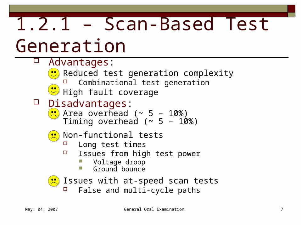
1.2.1 – Scan-Based Test Generation
Advantages: Reduced test generation complexity
Combinational test generation High fault coverage
Disadvantages: Area overhead (~ 5 – 10%)
Timing overhead (~ 5 – 10%)
Non-functional tests Long test times Issues from high test power
Voltage droop Ground bounce
Issues with at-speed scan tests False and multi-cycle paths

May. 04, 2007 General Oral Examination 8
1.2.2 – Sequential Test Generation Non-scan test generation Advantages
Functional vectors Short test times No test power issues
Ability to generate at-speed tests Disadvantages
High test generation complexity

May. 04, 2007 General Oral Examination 9
1.2.3 – RTL Test Generation Earlier Work [Jha et.al.,Hayes et. al.,Goloubeva et. al.] Advantages:
Low test generation complexity Less amount of information to process
Early detection of testability issues Synthesis independent
Disadvantages: Main issues
Closing gap between RTL and gate-level coverage High engineering effort
No established method

May. 04, 2007 General Oral Examination 10
1.2.4 – Pseudo Functional Test Generation Weighted random vectors (Brglez et. al.)
Test vectors generated with certain probabilities of being logic ‘0’ or ‘1’
PROPTEST (Guo et. al.) Property based test generation Probabilities, holding, perturbation
Spectral methods (Giani et. al., Khan et. al.) Test generation using spectral properties
Retrieve spectral properties Generate new vectors with those properties

May. 04, 2007 General Oral Examination 11
1.3 – Problem Definition Summary of goals
Generate functional test vectors Sequential test generation
Low test generation complexity RTL test generation
Convenient test generation method Spectral methods
Hence the problem is … To generate function vectors using sequential test
generation by using spectral methods at RTL

May. 04, 2007 General Oral Examination 12
Outline1. Introduction
2. Background
3. Spectral Register Transfer Level (RTL) test generation
4. RTL Design for Testability (DFT)
5. Results
6. Future Work
7. Conclusion

May. 04, 2007 General Oral Examination 13
2 – Background Spectral analysis for test generation Walsh functions and Hadamard matrix
May. 04, 2007 General Oral Examination 14
2.1 – Spectral Analysis for Test Generation
Spectral analysis: Interpret information in frequency domain
Test generation Good quality test vectors exhibit certain spectral
characteristics Goals:
Determine relevant spectral characteristics Generate vectors with those characteristics

May. 04, 2007 General Oral Examination 15
2.2 Walsh functions and Hadamard matrix
w0
w1
w2
w3
w4
w5
w6
w7Wal
sh f
unct
ions
(or
der
8)
time
1 1 1 1 1 1 1 11 -1 1 -1 1 -1 1 -11 1 -1 -1 1 1 -1 -11 -1 -1 1 1 -1 -1 11 1 1 1 -1 -1 -1 -11 -1 1 -1 -1 1 -1 11 1 -1 -1 -1 -1 1 11 -1 -1 1 -1 1 1 -1
H8 =
• Walsh functions: a complete orthogonal set of basis functions that can represent any arbitrary bit-stream.
• Walsh functions form the rows of a Hadamard matrix.
Example of Hadamard matrix of order 8
Move to next section

May. 04, 2007 General Oral Examination 16
Outline1. Introduction
2. Background
3. Spectral Register Transfer Level (RTL) test generation
4. RTL Design for Testability (DFT)
5. Results
6. Future Work
7. Conclusion

May. 04, 2007 General Oral Examination 17
3 – Spectral RTL Test Generation Spectral characterization Spectral vector generation Test set minimization

May. 04, 2007 General Oral Examination 18
3.1 – Spectral Characterization Purpose – Determine relevant spectral
characteristics Premise – Vectors detecting RTL faults
exhibit important spectral characteristics Steps
RTL fault modeling and test generation Spectral analysis

May. 04, 2007 General Oral Examination 19
3.1.1 – RTL Fault Modeling
CombinationalLogic
FF
FF
Inputs Outputs
RTL fault sites
A circuit is an interconnect of several RTL modules.

May. 04, 2007 General Oral Examination 20
3.1.2 – Spectral Analysis
0 to -1
Bit-stream
Vector 1Vector 2
.
.
.
Inp
ut
1
Inp
ut
2
. . .
Bit-stream ofInput 2

May. 04, 2007 General Oral Examination 21
3.1.2 – Spectral Analysis (cont.)
Bit stream to analyze
Correlating with Walsh functions by multiplying with Hadamard matrix.
Essential component (others regarded noise)
Hadamard Matrix H(3)
Bit stream
Spectral coeffs.

May. 04, 2007 General Oral Examination 22
Power Spectrum: “Ready” Signal
Noise level(1/128)
Examples of Essential
components
Examples of Noise
components
Nor
mal
ized
Pow
er
Spectral Coefficients
PARWANProcessor
Circuit

May. 04, 2007 General Oral Examination 23
Power Spectrum: A Random SignalN
orm
aliz
ed P
ower
Noise level(1/128)
Spectral Coefficients

May. 04, 2007 General Oral Examination 24
3.2 – Spectral Vector GenerationPerturbation
Generation of new bit-stream by multiplying with Hadamard matrix
Spectral components
Essential component
retained
noise components
randomly perturbed
New bit stream
Bits changed
Sign function
-1 to 0

May. 04, 2007 General Oral Examination 25
3.3 – Test Set Minimization Fault simulation of new sequences
Set of perturbation vector sequences {V1, V2, .. , VM} are generated.
Vector sequences are fault simulated and faults detected by each is obtained.
Minimization problem Find minimum set of vector sequences covering all the detected faults. Minimize Count{V1, … ,VM} to obtain compressed seq. {V1,… ,VC}
Fault Coverage{V1, … ,VC} = Fault Coverage{V1, … ,VM}
Compaction problem formulated as an Integer Linear Program (ILP) *.
* P. Drineas and Y. Makris, “Independent Test Sequence Compaction through Integer Programming," Proc. ICCD’03, pp. 380-386.
May. 04, 2007 General Oral Examination 26
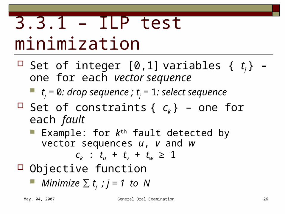
3.3.1 – ILP test minimization Set of integer [0,1] variables { tj } – one for
each vector sequence tj = 0: drop sequence ; tj = 1: select sequence
Set of constraints { ck } – one for each fault Example: for kth fault detected by vector sequences
u, v and w ck : tu + tv + tw ≥ 1
Objective function Minimize ∑ tj ; j = 1 to N

May. 04, 2007 General Oral Examination 27
3.3.2 – Hybrid LP – ILP Approximate solution to ILP (Relaxed LP, Rounding)* Algorithm:
1. All variables redefined as real [0,1] real variables(LP model)
2. Loop :1. Solve LP2. Round variables to add constraints
1. Round to 0 if ( 0.0 < variables ≤ 0.1)2. Round to 1 if ( 0.9 ≤ variables < 1.0)
3. Exit loop if no variables are rounded
3. Reconvert variables to [0,1] integers and solve ILP
* Kantipudi, K.R.; Agrawal, V.D, “A Reduced Complexity Algorithm for Minimizing N-Detect Tests”, 20th International Conference on VLSI Design, 2007

May. 04, 2007 General Oral Examination 28
Outline1. Introduction
2. Background
3. Spectral Register Transfer Level (RTL) test generation
4. RTL Design for Testability (DFT)
5. Results
6. Future Work
7. Conclusion

May. 04, 2007 General Oral Examination 29
4 – RTL Design for Testability Goals of DFT:
Improve fault coverage XOR tree as DFT
Low area overhead Low performance penalty Does not change state machine
Hard-to-detect RTL faults used for observation test points
Hard-to-detect RTL faults
To test output
XOR tree
May. 04, 2007 General Oral Examination 30
Outline1. Introduction
2. Background
3. Spectral Register Transfer Level (RTL) test generation
4. RTL Design for Testability (DFT)
5. Results
6. Future Work
7. Conclusion

May. 04, 2007 General Oral Examination 31
5 – Results Experimental Circuits Spectral RTL test generation
Stuck-at faults Transition delay faults

May. 04, 2007 General Oral Examination 32
5.1 – Experimental Circuits Experimental Circuits
4 ITC’99 high level RTL circuits
4 ISCAS’89 circuits. PARWAN processor*
Commercial sequential ATPG tool Mentor Graphics FlexTest for test generation and fault simulation.
Results obtained on Sun Ultra 5 machines with 256MB RAM.
Circuit benchmark PIs POs FFs
b01 ITC’99 2 2 5
b09 ITC’99 1 1 28
b11 ITC’99 7 6 31
b14 ITC’99 34 54 239
s1488 ISCAS’89 8 19 6
s5378 ISCAS’89 36 49 179
s9234 ISCAS’89 37 39 211
s35932 ISCAS’89 36 320 1728
PARWAN processor 11 23 53
* Z. Navabi, VHDL: Analysis and Modeling of Digital Systems, McGraw-Hill, 1993.

May. 04, 2007 General Oral Examination 33
5.2.1 – ATPG for stuck-at faults

May. 04, 2007 General Oral Examination 34
PARWAN* Processor
0
10
20
30
40
50
60
70
80
90
100
1 10 100 1000 10000
No. of Vectors
Te
st
co
ve
rag
e (
%) RTL spectral
ATPG
Gate-levelATPG
Randomvectors
RTL faultvectors
* Z. Navabi, VHDL: Analysis and Modeling of Digital Systems, McGraw-Hill, 1993.
May. 04, 2007 General Oral Examination 35
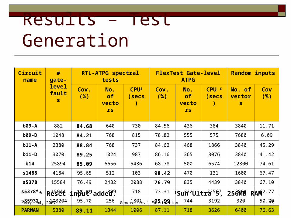
Results – Test Generation
Circuit name
# gate-level faults
RTL-ATPG spectral tests FlexTest Gate-level ATPG Random inputs
Cov. (%)
No. of vectors
CPU$ (secs)
Cov. (%)
No. of vectors
CPU $ (secs)
No. of vectors
Cov (%)
b09-A 882 84.68 640 730 84.56 436 384 3840 11.71
b09-D 1048 84.21 768 815 78.82 555 575 7680 6.09
b11-A 2380 88.84 768 737 84.62 468 1866 3840 45.29
b11-D 3070 89.25 1024 987 86.16 365 3076 3840 41.42
b14 25894 85.09 6656 5436 68.78 500 6574 12800 74.61
s1488 4184 95.65 512 103 98.42 470 131 1600 67.47
s5378 15584 76.49 2432 2088 76.79 835 4439 3840 67.10
s5378* 15944 73.59 1399 718 73.31 332 22567 2880 62.77
s35932 103204 95.70 256 1801 95.99 744 3192 320 50.70
PARWAN 5380 89.11 1344 1006 87.11 718 3626 6400 76.63* Reset input added. $Sun Ultra 5, 256MB RAM
May. 04, 2007 General Oral Examination 36
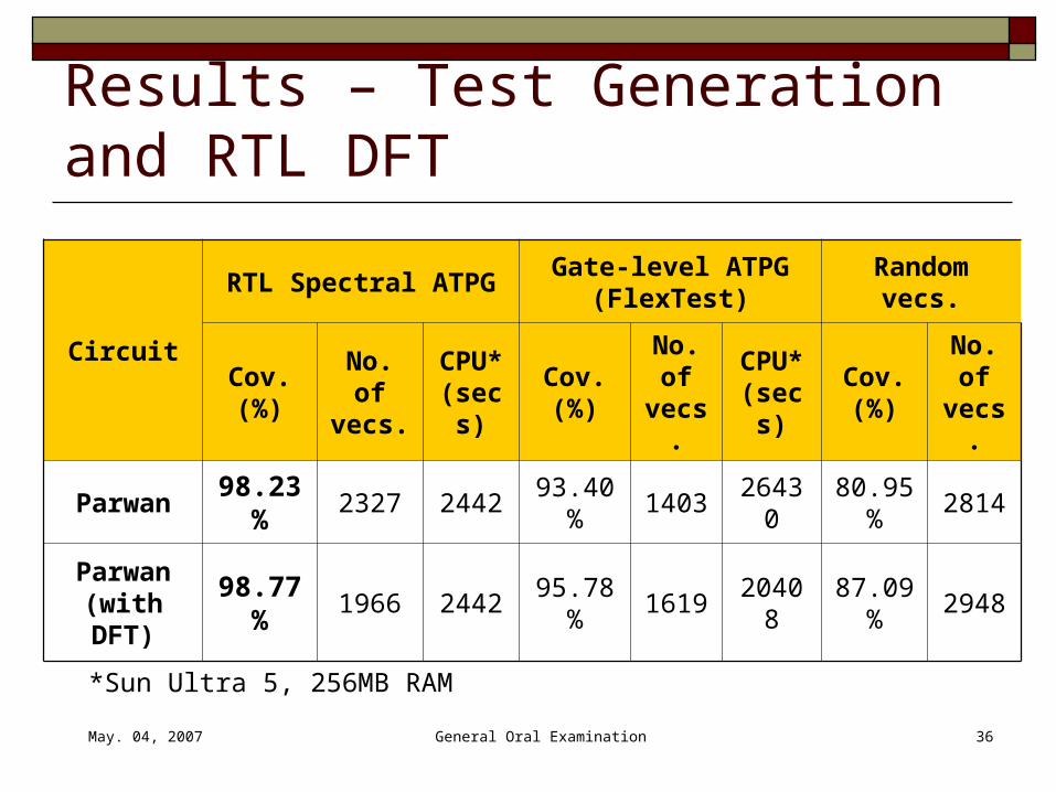
Results – Test Generation and RTL DFT
Circuit
RTL Spectral ATPGGate-level ATPG
(FlexTest)Random vecs.
Cov. (%)
No. of vecs.
CPU* (secs)
Cov. (%)
No. of vecs.
CPU* (secs)
Cov. (%)
No. of vecs.
Parwan 98.23% 2327 2442 93.40% 1403 26430 80.95% 2814
Parwan (with DFT)
98.77% 1966 2442 95.78% 1619 20408 87.09% 2948
*Sun Ultra 5, 256MB RAM

May. 04, 2007 General Oral Examination 37
5.2.2 – ATPG for transition faults

May. 04, 2007 General Oral Examination 38
Results – Test Generation
ATPG usedVersion of PARWAN
circuit
CPU secs.*
No. of vectors
Stuck-at fault cov.
(%)
Transition fault cov.
(%)
RTL-spectral for transition faults
Original 6428 6700 97.60 81.85
DFT for t-f 6428 5120 98.25 85.94
Gate-level FlexTest for transition faults
Original 43574 1318 92.44 73.79
DFT for t-f 40119 1444 96.29 81.90
Random vectorsOriginal 51200 82.28 58.67
DFT for s-a-f 51200 86.20 65.82
* Sun Ultra 5, 256MB RAMs-a-f: stuck-at faults t-f : transition faults

May. 04, 2007 General Oral Examination 39
Outline1. Introduction
2. Background
3. Spectral Register Transfer Level (RTL) test generation
4. RTL Design for Testability (DFT)
5. Results
6. Future Work
7. Conclusion

May. 04, 2007 General Oral Examination 40
6 – Future Work
Fourier Analysis of Digital Waveforms Spectral BIST

May. 04, 2007 General Oral Examination 41
6.1 – Fourier Analysis of Digital Waveforms Fourier Transform – converts signals to frequency domain Digital bit-streams can be perceived as sampled analog signals Important properties (not exhibited by Walsh functions)
Frequency decomposition using Fourier transform is invariant to phase or circular time-shift
Multiplication = Convolution (frequency domain) (time domain)
Other advantages of Fourier Transform over Walsh Established methods for noise analysis Methods to find Power Spectral Density (PSD)

May. 04, 2007 General Oral Examination 42
Wrapper
6.2.1 – Built-In Self Test Built-In Self Test (BIST)
Hardware inserted to: Generate test vectors Capture responses of CUT Flag CUT good or bad Circuit Under
Test (CUT)
Test generator
System Inputs
System Outputs
Response Analyzer
CUT status

May. 04, 2007 General Oral Examination 43
Motivation for Spectral BIST BIST
Advantages: No need of expensive Automatic Test Equipment (ATE) Testing during operation and maintenance Supports system level test Supports at-speed testing And many more …
Disadvantages: Low coverage test vectors Area / timing overhead
Problem is… To design a test pattern generator with spectral information
that generates high coverage test vectors

May. 04, 2007 General Oral Examination 44
Fourier Transform of Test Bit-Stream
Prominent features

May. 04, 2007 General Oral Examination 45
6.2.2 – Spectral BIST
Wrapper
Circuit Under Test (CUT)
Test generator
System Inputs
Response Analyzer
CUT status
Spectral Filter
System Outputs
Spectral Test Generator

May. 04, 2007 General Oral Examination 46
Digital Filter Design If y : output of filter
x : input of filter n : time period p : order of filter Infinite Impulse Response (IIR)
y(n) = f (y(n-1), ….. y(n-p), x(n), x(n-1), … x(n-p)) Finite Impulse Response (FIR)
y(n) = f (x(n), x(n-1), … x(n-p))
IIR would require more hardware than FIR

May. 04, 2007 General Oral Examination 47
Spectral Test Generator
Test generator
Spectral Filter
Spectral Test Generator
LFSR
FIR filter

May. 04, 2007 General Oral Examination 48
FIR Filter DesignFIR filter
May. 04, 2007 General Oral Examination 49
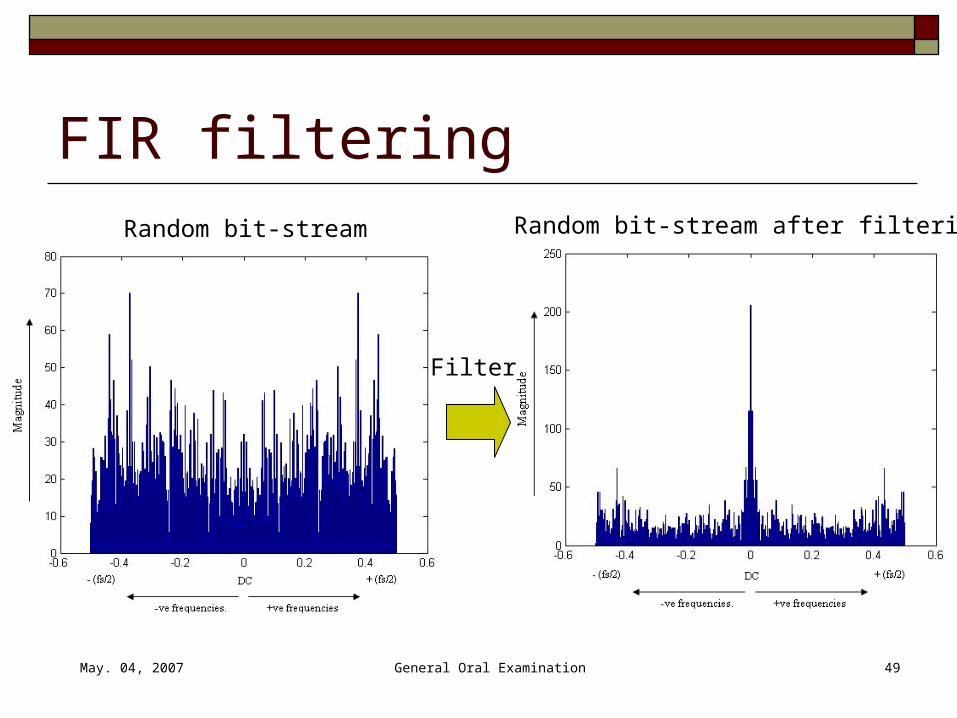
FIR filteringRandom bit-stream Random bit-stream after filtering
Filter

May. 04, 2007 General Oral Examination 50
How good is the filtered bit-stream ?Original test bit-stream Random bit-stream after filtering

May. 04, 2007 General Oral Examination 51
Results - ComparisonTest Set
No. of vectors
No. of faults detected
Total no. of faults
Test cov. (%)
RTL vectors 112 325 485 76.86 %
Flextest vectors 1410 364 485 84.09 %
Random vectors 65000 44 485 12.51 %
Filtered vectors 65000 364 485 84.09 %
s382
s526
Test SetNo. of
vectorsNo. of faults
detectedTotal no. of
faultsTest cov.
(%)
RTL vectors 103 339 639 59.21 %
Flextest vectors 1950 448 639 76.72 %
Random vectors 65000 55 639 10.75 %
Filtered vectors 65000 450 639 76.88 %

May. 04, 2007 General Oral Examination 52
Results – Graphs s382 - Test Coverage vs No. of Vectors
0
20
40
60
80
100
1 10 100 1000 10000 100000
No .of Vectors
Te
st
Co
ve
rag
e
Random Filtered Random
May. 04, 2007 General Oral Examination 53
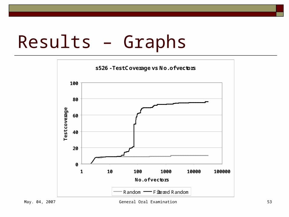
Results – Graphs s526 - Test Coverage vs No. of vectors
0
20
40
60
80
100
1 10 100 1000 10000 100000
No. of vectors
Te
st
co
ve
rag
e
Random Filtered Random

May. 04, 2007 General Oral Examination 54
Conclusion We have presented a new method for gate-level test
generation using spectral methods at RTL Proposed Spectral RTL ATPG technique applied to
ITC’99 and ISCAS’89 benchmarks, and a processor circuit
In most cases, Spectral RTL ATPG gave similar or better test coverage in shorter CPU time as compared to commercial sequential ATPG tool FlexTest
Proposed RTL DFT technique enhanced fault coverages

May. 04, 2007 General Oral Examination 55
Conclusion – Future Work Investigate Fourier analysis of digital bit-
streams Compare Walsh and Fourier analysis Investigate their use for signature analysis
Research on spectral test generator for BIST Experiment with different designs of LFSR Efficient design of spectral filter

May. 04, 2007 General Oral Examination 56
Questions ?
Thank You !