gate solutions - iesmasterpublications.com · 3. symmetrical components and fault calculations...
TRANSCRIPT


GATE SOLUTIONSE L E C T R I C A L E N G I N E E R I N G
From (1991 - 2017)
Office : Phone : F-126, (Lower Basement), Katwaria Sarai, New Delhi-110016 011-26522064
Mobile : E-mail:
Web :
8130909220, 9711853908 [email protected], [email protected]
iesmasterpublications.com, iesmaster.org

Second Edition : 2017
Typeset at : IES Master Publication, New Delhi-110016
IES MASTER PUBLICATIONF-126, (Lower Basement), Katwaria Sarai, New Delhi-110016Phone : 011-26522064, Mobile : 8130909220, 9711853908E-mail : [email protected], [email protected] : iesmasterpublications.com, iesmaster.org
All rights reserved.Copyright © 2017, by IES MASTER Publications. No part of this booklet may be reproduced,or distributed in any form or by any means, electronic, mechanical, photocopying, recording,or otherwise or stored in a database or retrieval system without the prior permission ofIES MASTER, New Delhi. Violates are liable to be legally prosecuted.

PREFACE
It is an immense pleasure to present topic wise previous years solved paper of GATE Exam.This booklet has come out after long observation and detailed interaction with the studentspreparing for GATE exam and includes detailed explanation to all questions. The approach hasbeen to provide explanation in such a way that just by going through the solutions, students willbe able to understand the basic concepts and will apply these concepts in solving other questionsthat might be asked in future exams.
GATE exam now a days has become more important because it not only opens the door forhigher education in institutes like IIT, IISC, NIT's but also many of the PSUs have started inductingstudents on the basis of GATE score. In PSU’s, which are not inducting through GATE route, thequestions in their exams are asked from GATE previous year papers. Thus, availability of authenticsolutions to the students is the need of the day. Towards this end this booklet becomesindispensable.
I am thankful to IES master team without whose support, I don't think, this book could have beenflawlessly produced.
Every care has been taken to bring an error free book. However comments for future improvementare most welcome.
Mr. Kanchan Kumar ThakurDirector Ex-IES


1. Power Systems ................................................................................... 01 – 120
2. Electrical Machines ............................................................................ 121– 240
3. Power Electronics ............................................................................. 241 – 312
4. Electrical and Electronic Measurements ............................................ 313 – 370
5. Control System .................................................................................. 371 – 472
6. Electromagnetic Field Theory ............................................................ 473 – 506
7. Digital Electronics & Microprocessors ............................................... 507 – 552
8. Analog Electronics ............................................................................ 553 – 636
9. Circuit Theory .................................................................................... 637 – 738
10. Signals and Systems ......................................................................... 739 – 798
11. Engineering Mathematics .................................................................. 799 – 852
12. General Ability ................................................................................... 853 – 885
CONTENTS
1. Generating Power Stations and Per Unit System ---------------- 01–06
2. Overhead Transmission Lines (Line parameters,Performance of lines, HVDC, Corona, Cables,Insulators & Distribution Systems) ----------------------------------- 07–38
3. Symmetrical Components and Fault Calculations --------------- 39–62
4. Power System Stability -------------------------------------------------- 63–78
5. Load Flow -------------------------------------------------------------------- 79–93
6. Economic Load Dispatch and Load Frequency Control -------- 94–102
7. Voltage Control and Compensation in Power System -------- 103–110
8. Power System Protection --------------------------------------------- 111–120
Power generation concepts, ac and dc transmission concepts, Models and performanceof transmission lines and cables, Series and shunt compensation, Electric fielddistribution and insulators, Distribution systems, Per-unit quantities, Bus admittancematrix, Gauss Seidel and Newton-Raphson load flow methods, Voltage and frequencycontrol, Power factor correction, Symmetrical components, Symmetrical andunsymmetrical fault analysis, Principles of over-current, differential and distanceprotection; Circuit breakers, System stability concepts, Equal area crterion.
Syllabus
Contents
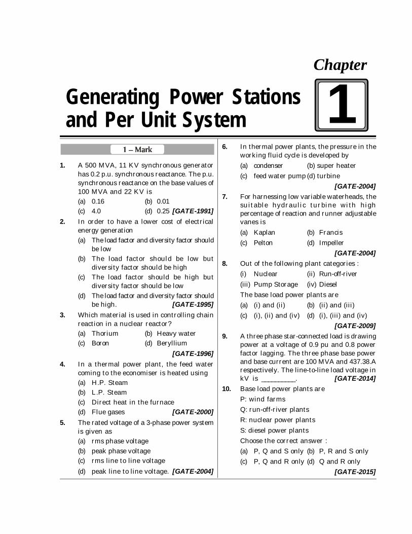
1. A 500 MVA, 11 KV synchronous generatorhas 0.2 p.u. synchronous reactance. The p.u.synchronous reactance on the base values of100 MVA and 22 KV is(a) 0.16 (b) 0.01(c) 4.0 (d) 0.25 [GATE-1991]
2. In order to have a lower cost of electricalenergy generation(a) The load factor and diversity factor should
be low(b) The load factor should be low but
diversity factor should be high(c) The load factor should be high but
diversity factor should be low(d) The load factor and diversity factor should
be high. [GATE-1995]3. Which material is used in controlling chain
reaction in a nuclear reactor?(a) Thorium (b) Heavy water(c) Boron (d) Beryllium
[GATE-1996]4. In a thermal power plant, the feed water
coming to the economiser is heated using(a) H.P. Steam(b) L.P. Steam(c) Direct heat in the furnace(d) Flue gases [GATE-2000]
5. The rated voltage of a 3-phase power systemis given as(a) rms phase voltage(b) peak phase voltage(c) rms line to line voltage(d) peak line to line voltage. [GATE-2004]
6. In thermal power plants, the pressure in theworking fluid cycle is developed by(a) condenser (b) super heater(c) feed water pump (d) turbine
[GATE-2004]7. For harnessing low variable waterheads, the
suitable hydraulic turbine with highpercentage of reaction and runner adjustablevanes is(a) Kaplan (b) Francis(c) Pelton (d) Impeller
[GATE-2004]8. Out of the following plant categories :
(i) Nuclear (ii) Run-off-river(iii) Pump Storage (iv) DieselThe base load power plants are(a) (i) and (ii) (b) (ii) and (iii)(c) (i), (ii) and (iv) (d) (i), (iii) and (iv)
[GATE-2009]9. A three phase star-connected load is drawing
power at a voltage of 0.9 pu and 0.8 powerfactor lagging. The three phase base powerand base current are 100 MVA and 437.38.Arespectively. The line-to-line load voltage inkV is __________. [GATE-2014]
10. Base load power plants areP: wind farmsQ: run-off-river plantsR: nuclear power plantsS: diesel power plantsChoose the correct answer :(a) P, Q and S only (b) P, R and S only(c) P, Q and R only (d) Q and R only
[GATE-2015]
Generating Power Stationsand Per Unit System
Chapter
1
8010009955, 9711853908 [email protected], [email protected]. : E-mail:
Regd. office : Phone : F-126, (Upper Basement), Katwaria Sarai, New Delhi-110016 011-41013406
POWER SYSTEM 3
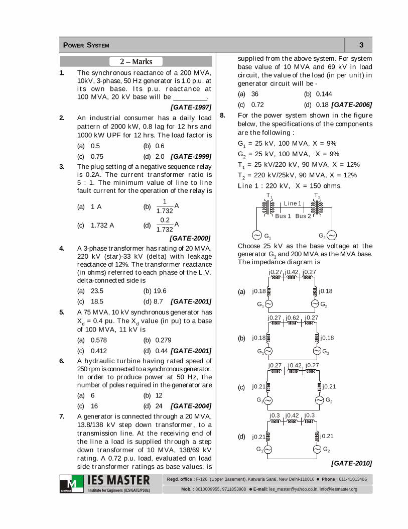
1. The synchronous reactance of a 200 MVA,10kV, 3-phase, 50 Hz generator is 1.0 p.u. atits own base. Its p.u. reactance at100 MVA, 20 kV base will be __________.
[GATE-1997]2. An industrial consumer has a daily load
pattern of 2000 kW, 0.8 lag for 12 hrs and1000 kW UPF for 12 hrs. The load factor is(a) 0.5 (b) 0.6(c) 0.75 (d) 2.0 [GATE-1999]
3. The plug setting of a negative sequence relayis 0.2A. The current transformer ratio is5 : 1. The minimum value of line to linefault current for the operation of the relay is
(a) 1 A (b)1 A
1.732
(c) 1.732 A (d)0.2 A
1.732[GATE-2000]
4. A 3-phase transformer has rating of 20 MVA,220 kV (star)-33 kV (delta) with leakagereactance of 12%. The transformer reactance(in ohms) referred to each phase of the L.V.delta-connected side is(a) 23.5 (b) 19.6(c) 18.5 (d) 8.7 [GATE-2001]
5. A 75 MVA, 10 kV synchronous generator hasXd = 0.4 pu. The Xd value (in pu) to a baseof 100 MVA, 11 kV is(a) 0.578 (b) 0.279(c) 0.412 (d) 0.44 [GATE-2001]
6. A hydraulic turbine having rated speed of250 rpm is connected to a synchronous generator.In order to produce power at 50 Hz, thenumber of poles required in the generator are(a) 6 (b) 12(c) 16 (d) 24 [GATE-2004]
7. A generator is connected through a 20 MVA,13.8/138 kV step down transformer, to atransmission line. At the receiving end ofthe line a load is supplied through a stepdown transformer of 10 MVA, 138/69 kVrating. A 0.72 p.u. load, evaluated on loadside transformer ratings as base values, is
supplied from the above system. For systembase value of 10 MVA and 69 kV in loadcircuit, the value of the load (in per unit) ingenerator circuit will be -(a) 36 (b) 0.144(c) 0.72 (d) 0.18 [GATE-2006]
8. For the power system shown in the figurebelow, the specifications of the componentsare the following :G1 = 25 kV, 100 MVA, X = 9%G2 = 25 kV, 100 MVA, X = 9%T1 = 25 kV/220 kV, 90 MVA, X = 12%T2 = 220 kV/25kV, 90 MVA, X = 12%Line 1 : 220 kV, X = 150 ohms.
T1 T2
G1 G2
Line 1
Bus 1 Bus 2
Choose 25 kV as the base voltage at thegenerator G1 and 200 MVA as the MVA base.The impedance diagram is
(a)
j0.27 j0.42
j0.18
G1 G2
j0.27
j0.18
(b)
j0.27 j0.62
j0.18
G1 G2
j0.27
j0.18
(c)
j0.27 j0.42
j0.21
G1 G2
j0.27
j0.21
(d)
j0.3 j0.42
j0.21
G1 G2
j0.3
j0.21
[GATE-2010]

8010009955, 9711853908 [email protected], [email protected]. : E-mail:
Regd. office : Phone : F-126, (Upper Basement), Katwaria Sarai, New Delhi-110016 011-41013406
4 GATE SOLVED PAPER 1991-2017
7. (a)
8. (a)
9. (118.8kV)
10. (d)
:: 2 MARKS ::
1. (0.125 p.u.)
2. (c)
3. (c)
4. (b)
5. (d)
6. (d)
7. (b)
8. (b)
:: 1 MARK ::
1. (b)
2. (d)
3. (c)
4. (d)
5. (c)
6. (c)
Sol–1: (b)
Z(p.u.)new = 2
old newold
new old
KV MVAZ(p.u.) KV MVA
= 2 100110.2
50022
= 0.220 = 0.01
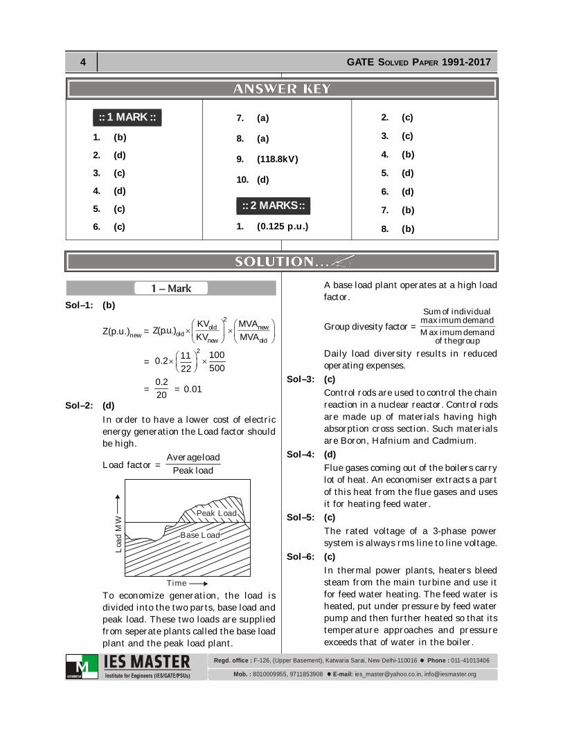
Sol–2: (d)In order to have a lower cost of electricenergy generation the Load factor shouldbe high.
Load factor = Averageload
Peak load
Load
MW
Peak Load
Base Load
TimeTo economize generation, the load isdivided into the two parts, base load andpeak load. These two loads are suppliedfrom seperate plants called the base loadplant and the peak load plant.
A base load plant operates at a high loadfactor.
Group divesity factor = Sumof individual
max imumdemandMax imumdemand
of thegroupDaily load diversity results in reducedoperating expenses.
Sol–3: (c)Control rods are used to control the chainreaction in a nuclear reactor. Control rodsare made up of materials having highabsorption cross section. Such materialsare Boron, Hafnium and Cadmium.
Sol–4: (d)Flue gases coming out of the boilers carrylot of heat. An economiser extracts a partof this heat from the flue gases and usesit for heating feed water.
Sol–5: (c)The rated voltage of a 3-phase powersystem is always rms line to line voltage.
Sol–6: (c)In thermal power plants, heaters bleedsteam from the main turbine and use itfor feed water heating. The feed water isheated, put under pressure by feed waterpump and then further heated so that itstemperature approaches and pressureexceeds that of water in the boiler.
8010009955, 9711853908 [email protected], [email protected]. : E-mail:
Regd. office : Phone : F-126, (Upper Basement), Katwaria Sarai, New Delhi-110016 011-41013406
POWER SYSTEM 5
=210 1001. .
20 200
=1 p.u.8 = 0.125 p.u.
Sol–2: (c)
Load factor =Average Demand
Maximum DemandAverage demand in 24 hrs.
= 12 100012 200024
= 120002400024
= 36000 kW24
= 1500 kWMaximum demand in 24 hrs is given as2000 kW
Load factor = Average Demand
Maximum Demand
= 15002000
= 3 0.754
Sol–3: (c)The given is a L-L faultHere If = R1 R23I 3I
and R1I = R2IPlug setting of the negative sequence relayis 0.2A.Pick up current = Plug setting × CT ratio
= 50.2 1 Amp.1
1 Amp. is the negative sequence current.So, If = f 23 I
= 3 1= 1.732 Amp.
Sol–4: (b) Base impedance on L.V. side
=2
B
(kV)(MVA) =
23320
= 54.45
Sol–7: (a) Propeller turbine is a reaction turbine
suitable for low head and large quantityof water. It is suitable for heads below30m.
A Kaplan turbine is a propeller turbinewith adjustable blades, the advantageof adjustable blades being that a Kaplanturbine operates at high efficiency evenunder part load conditions.
Sol–8: (a)Nuclear and Run-off-river plants are thebase load plant and Pumped Storage andDiesel plants are peak load plants.Note : A base load plant operates at ahigh load factor and should be one whichhas low operating costs.The peak load plant operates at a low loadfactor.
Sol–9: (118.8kV)
Base kV = Base kVA3 Base current,A
=3100 10
3 437.38
= 132 kV
Actual line to line voltage= (p.u. value) × Base voltage= 0.9 × Base voltage= 0.9 × 132 = 118.8kV
Sol–10: (d)Diesel plants are very costly and thus notused as base load plants.Wind plants are intermittent and hencethey can’t serve as base load plants.Run off river plants are base load plants.Nuclear plants aren’t turned on/offfrequently due to safety and economicreasons hence used as base load plants.
Sol–1: (0.125 p.u.)
p.u.,newZ =2
old newp.u.,old
new old
kV MVAZ . .kV MVA


8010009955, 9711853908 [email protected], [email protected]. : E-mail:
Regd. office : Phone : F-126, (Upper Basement), Katwaria Sarai, New Delhi-110016 011-41013406
6 GATE SOLVED PAPER 1991-2017
(kA)B new = 3 3 13 8
B B
new
(MVA) (MVA).(kV) .
Actual load current, L L pu B oldI I (kA)
pu current on generator side;
Ip.u.new =
B old
p.u.oldB new
(kA)I(kA)
= 13 80 7269
..
= 0.144Sol–8: (b)
Given, kVbase = 25kV, MVAbase = 200 MVAPer unit reactance of
G1 =2200 25j0.09
100 25
= j0.18Per unit reactance of
G2 =2200 25j0.09
100 25
= j0.18Per unit reactance of
T1 =2200 25j0.12
90 25
= j0.27
Per unit reactance of line = actual
base
XX
= 2
150 200220
= j0.62Per unit reactance of
T2 =2200 220j0.12
90 220
= j0.27The impedance diagram of the powersystem is
j0.27 j0.62
j0.18
G1 G2
j0.27
j0.18
Leakage reactance in (on LV side)= 54.45 × 0.12= 6.534
So reactance per phase = 6.35In connection, if the impedance in eacharm is Z1, then per phase impedance (i.e.between phase and neutral) can bedetermine by converting equivalent star(Y).
Zph = 1Z3 Z1 = 3.Zph
= 3 × 6.534= 19.6
Sol–5: (d)Xd (in pu) on new base
= 2
new oldd 2
old new
(MVA) (kV )X .old(MVA) (kV )
=
2100 100.4 0.44 p.u.75 11
Sol–6: (d) Rated speed of hydraulic turbine = 250
rpm Output frequency of generator = 50 HzIf no of pole = P, then
N = 120fP
or P = 120N
f = 120 50 24250
No. of pole required = 24Sol–7: (b)
G
T1 T2 IL
Load20 MVA 13.8 / 138 kV
10 MVA 138 / 69 kV
Base current on load side
(kA)B = 3
B
B
(MVA)(kV)
(IL = 0.72 is given on 69 kV)(kA)B on Generator side,