gates mobilecrimp 4 20 safety & operating manual (positive
TRANSCRIPT


Carefully read and understand the following warnings before operating this crimper.
WARNING!An incorrect hose assembly can rupture or blow apart in use, resulting in serious injury, death
or property damage. REMEMBER: Others depend on you to make correct assemblies.
FOR SAFETY’S SAKE
USE THIS MACHINE ONLY IF YOU:
1. Receive hands-on TRAINING with the MobileCrimp® 4-20 and Gates assemblies.
2. Follow current GATES OPERATING MANUAL AND CRIMP DATA for the MobileCrimp 4-20.
3. Use only NEW (UNUSED) GATES hose and fittings.
4. Wear SAFETY GLASSES.
5. KEEP HANDS CLEAR OF MOVING PARTS. Support hose with one hand while activatingpump with other hand.
6. DO NOT operate pump UNLESS cylinder is locked in crimp position.
7. To avoid risk of injury, DO NOT use crimper UNLESS CONTROLLER BASE PLATE is in place.
8. DO NOT operate crimper in horizontal position.
Positive Stop Control
Prod. No.: 7480-0050, Part No.: 77420
Dimensions: 12 1/4" wide x 6 1/4"deep x 17 3/4" high
Weight: 57 lbs. (with stand)
Positive Stop Control
®
4 20
MobileCrimp®
Shop Air PumpProd. No.: 7481-0002, Part No.: 77820Weight: 10 lbs.
1/4 H.P. 12 Volt DC PumpProd. No.: 7481-0037, Part No.: 77439Weight: 20.5 lbs.
1/2 H.P. 115 Volt AC PumpProd. No.: 7481-0034, Part No.: 77441Weight: 32 lbs.
Hand PumpProd. No.: 7481-0006, Part No.: 77821Weight: 25.6 lbs.
1/4 H.P. 115 Volt AC PumpProd. No.: 7481-0033, Part No.: 77440Weight: 20 lbs.
1-1/2 H.P. 115 Volt AC PumpProd. No.: 7481-0035, Part No.: 77442Weight: 108 lbs.
Pump SpecificationsAll pumps maximum rated working pressure: 10,000 psi

1
Contents
Identification List ...........................................................................................2
Setup ..............................................................................................................3
Hose Preparation ............................................................................................6
Operating Instructions ....................................................................................8
Measuring and Adjusting the Crimp Diameter ..............................................12
Maintenance .................................................................................................13
Troubleshooting ............................................................................................14
Replacement Parts List ..................................................................................15
Warranty ................................................................................inside back cover
Serial No. _______________(Located on front top of cylinder)
Date of Purchase _________
®
4 20
MobileCrimp®
1

®
4 20
MobileCrimp®
2
Spacer Rings
Die
Pressure Plate
Hose Assembly
Literature Packet Magnet
Clamps
Stand
Molykote and Brush
Crimper
Identification List

3
®
4 20
MobileCrimp®
Setup1. Unpack carton.• Remove crimper, pressure plate (1),
nylon-covered hose assembly (1), literature envelope (1), stand (2 pieces),magnet (1) and Molykote lubricant (1)from shipping carton. Locate the serialnumber assigned to the crimper on thetop front of the cylinder and record onpage one for future reference.
2. Attach crimper to the stand.• Place crimper on flat, well-supported
surface (such as the top of a workbench or the bed of a service vehicle) with thehandle to the right.
• Remove two (2) knobs, flat washers (2)and spacer (1) from crimper pivot bolts.
• Slide the two halves of the stand together and attach to the crimper at the pivot bolts.
• Replace spacer, flat washers and knobs.Do not tighten knobs.
• Lift crimper and allow stand to swingdown onto the surface. Tighten knobs.
Left Side
Right Side
spacer

®
4 20
MobileCrimp®
4
3. Fasten crimper to work surfacebefore use (to avoid damage tomachine or personal injury because an unsecured machine can fall).
• Position crimper so that mounting holesare approximately 7" to 8" from theedge of the work surface.
• Mark the drilling location using themounting holes as a guide (see illustra-tion below).
• Drill two 5/16" diameter holes.
• Use mounting holes or clamps to fastenstand to work surface.
4. Attach pump to crimper.• Place pump near crimper.
• Connect hose assembly to the pumpport (3/8" NPT threads). Pipe sealantmay be used to seal connection. (Forbest connection, use Gates’ QuickDisconnect couplings, G95311-0606and G95321-0600, sold separately.)
• Connect opposite end to the adapter on crimper.
5. Check pump oil level.• Pump comes with oil in reservoir.
• Check proper oil level per pump operating manual instructions or theMaintenance Section (p. 13) of this manual.
Edge of work
surface
(2) 5/16" diameter holes
7 1/2" 11"
clamps
mounting holes
To avoid damage tothe machine or injury
to you, ALWAYS fastenthe crimper to the work
surface before you attempt to crimp.

5
®
4 20
MobileCrimp®
6. Connect pump to power outlet.• For 115V connection, plug power cord
into a properly grounded and rated circuit(see inside cover for circuit requirements).
• For vehicle battery connection, seepump operating manual.
7. Bleed air from system.• Tilt crimper forward so adapter is at
its highest point.
• Turn pump on by pressing and holdingthe power ”on“ switch, (see pumpoperating manual for switch location)which extends the ram.
• Extend the ram approximately 1".Release “on” switch allowing ram to fully retract.
• Repeat a minimum of five (5) times tobleed air completely.
8. Place crimper in comfortableworking position.
• See photo below for suggested workingposition.
IMPORTANT
Do not operate crimper in horizontal position because dies will become unstable.
Note: It’s a goodidea to place a
rubber mat on thefloor near the crimper
to reduce the chance of damag-ing a die if dropped and improveoperator comfort.

®
4 20
MobileCrimp®
6
Hose PreparationMegaCrimp® Pre-AssembledCouplings.
1. Cut hose to desired length.
2. Using Gates crimp data chart #35019(Ind), 428-7365 (Auto), select the correct coupling or visit our websiteto download our electronic programat www.gates.com/ecrimp.
3. Place a visible mark on hose cover at the insertion length shown on thecrimp data chart.
4. Insert coupling into the hose until the mark lines up with the end of the coupling ferrule.
5. Hose and coupling are now ready for crimping.
CAUTION
A new hose and end fittings(stem/ferrule) must be used
when building a hose assembly.Re-using any components will
seriously affect performance andcould result in serious injury or
property damage.

7
®
4 20
MobileCrimp®
GlobalSpiral™ Two-Piece Couplings.
1. Cut hose to desired length.
2. Using Gates crimp data chart #35019-(Ind), 428-7365 (Auto), select the correct stem and ferrule or visit ourwebsite to download our electronicprogram at www.gates.com/ecrimp.
3. Place ferrule over end of hose.
4. Lubricate the first two or three serrations on stem with lightweightoil (SAE 10W).
5. Clamp stem in vise on hex portion,and push hose onto stem.
Hose should be flush against stem shoulder (see cutaway drawing below).
6. Hose and coupling are now ready for crimping.
CAUTION
A new hose and end fittings(stem/ferrule) must be used
when building a hose assembly.Re-using any components will
seriously affect performance andcould result in serious injury or
property damage.

®
4 20
MobileCrimp®
8
OperatingInstructions1. Select correct die set.• Using Gates crimp data chart #35019
(Ind), 428-7365 (Auto) or ecrimp, selectcorrect die set for the hose and couplingbeing crimped.
2. Lubricate and load die.• Swing cylinder to ”die loading” position.
• Apply thin layer of Molykote* lube to the inside surface of the die cone.Re-apply lube whenever surface becomes shiny.
• Using the magnet, place the die set into the die cone.
• Remove magnet by lifting the ”T” handle, making sure the top of the die fingers are even.
• Apply a thin layer of Molykote lube to the top of the die set.
* Use only Gates Molykote lube for proper operationor Gates-recommended grease.
die set
Important Note:Lubricants should be
reapplied to metal-to-metal sliding surfaces
whenever the surface becomes shiny.Failure to do this reduces the life ofthe dies and cone. Excessive wear onthese components produces poorlyperforming hose assemblies thatcould blow apart and result in injury.
9
®
4 20
MobileCrimp®
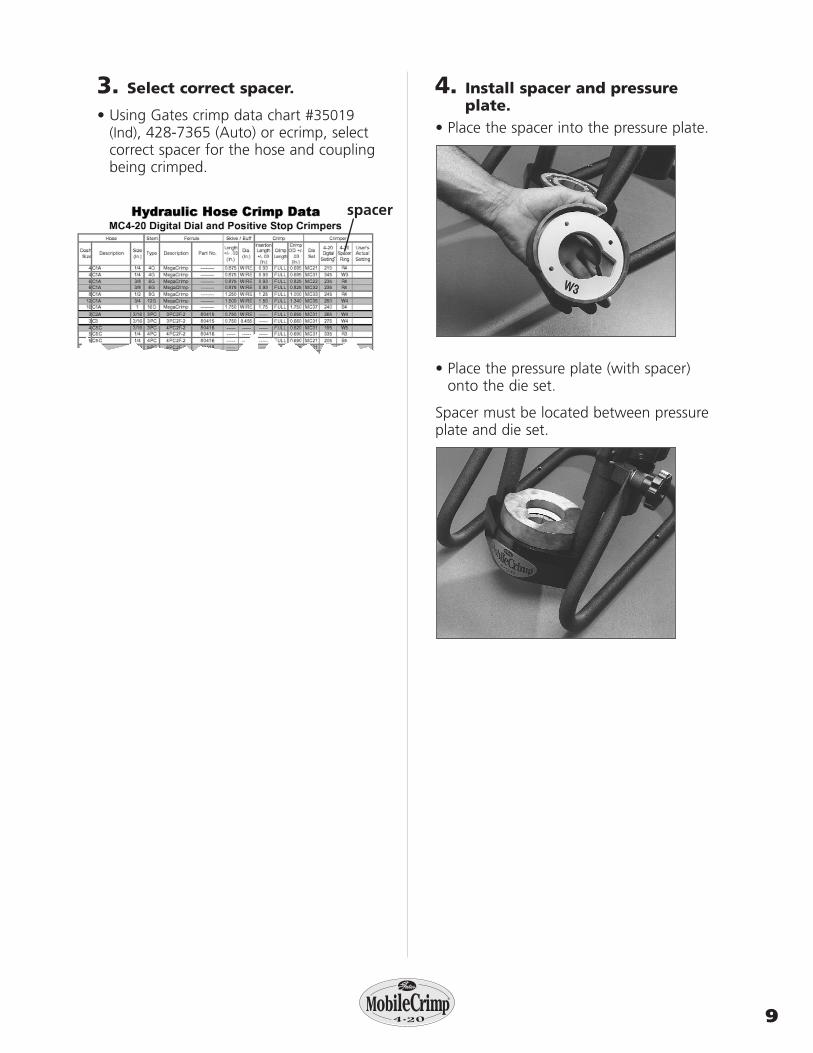
3. Select correct spacer.
• Using Gates crimp data chart #35019(Ind), 428-7365 (Auto) or ecrimp, selectcorrect spacer for the hose and couplingbeing crimped.
4. Install spacer and pressureplate.
• Place the spacer into the pressure plate.
• Place the pressure plate (with spacer)onto the die set.
Spacer must be located between pressureplate and die set.
spacer

®
4 20
MobileCrimp®
10
5. Insert hose assembly.• Insert assembly from the bottom of the
die cone up through the die set.
• Locate the top of the ferrule approximately 1/16"below the top of the die set.
• When crimping bent tube and block-style couplings, keep thread end alignedwith notch in pressure plate and spacer.
6. Swing cylinder into crimpingposition.
• Using the handle, swing cylinder toward you and lock into place withlock pin.
IMPORTANT
For GS couplings, make sure the top of the ferrule rests against the hex or round shoulder of the coupling.

11
®
4 20
MobileCrimp®
• Make sure cylinder is locked into posi-tion by placing lock pin into hole on top of cylinder.
7. Begin the crimp.• Start pump by steadying hose with one
hand while pressing and holding the power “on”switch with the otherhand, which extends the ram (see pumpoperation manual for switch location).
• When pressure plate contacts the top of the die cone, release the power “on”switch. Crimp is now complete.
8. Remove hose assembly.• While holding hose, lightly lift bottom
of die set to release hose assembly.
• Remove hose assembly.
Serious injury and/or crimper damage can result if the cylinderis not locked in its crimp position.
IMPORTANT
lock pin
Keep away from all moving parts!If bodily contact with a moving part
occurs, immediately release the pump power “on“ switch.
Incorrect Correct
CAUTION

12
®
4 20
MobileCrimp®
Measuring andAdjusting theCrimp Diameter
1. Measure the crimp diameter.
When using 21 and 22 Dies
• Using Gates “21/22” dial calipers(Product No. 7369-1320, Part No. 78217)measure halfway between ridges (Fig. 1).To be sure crimp diameter is being properly measured, mark a crimp flat.Beginning with that flat, count 9 flats toget the diameter. Be sure caliper bladesDO NOT touch ridges. (See Photo 3.)
• Measure halfway betweenthe ends of crimped portionof the ferrule (Fig. 2).
When NOT using 21 and 22 Dies
• Using Gates dial calipers(Product No. 7369-0320,Part No. 78215) whichare notched to clearridges, measure halfwaybetween ridges (Sketch1). Be sure caliper fingersDO NOT touch ridges orpart number stamps.(See Photo 3.)
• Measure halfwaydown the crimpedportion of the ferrule(Sketch 2).
2. Check crimp diameter.• The measured crimp diameter must be
within 0.010"of the published crimpdiameter. If not, the hose assembly cannot be used, and adjustment will be required.
3. Adjust the crimp diameter (if necessary).
• Check top of die set and the surfaces of the pressure plate for any debris(metal chips, dirt, etc.). Debris maycause some variation in crimp diameter.
• If necessary, clean the surfaces and lightly lubricate with Molykote.
4. Multiple crimps.• When crimping multiple assemblies,
check every tenth crimp to ensure diameter is within acceptable range (± 0.010").
DO NOT measure on top of part number stamps.
NOTE:
FIG. 1
CRIMP DIA.
CALIPER RIDGES
SKETCH 1
CRIMPDIA.
SKETCH 2
FIG. 2
PHOTO 3

13
®
4 20
MobileCrimp®
MaintenanceThis crimper requires minimal maintenance.However, the following practices are recommended to ensure maximum reliability and service.
Lubricate.• Using the small brush and Molykote,
apply a light coat to the inside surfaceof the die cone whenever it becomesshiny.
Check oil level.• Check the hydraulic oil level in the
pump reservoir after each 10 hours ofuse (see pump operation manual forinstructions).
• If the oil is more than 1/2" below thetop, add a high-grade hydraulic oil suchas Mobil DTE 25 until within 1/2" of thetop of the reservoir.
Change the oil.(NOTE: Frequency depends on thepump’s general working conditions, severity of use and overall cleanliness.)
• For general shop conditions, change oil every 300 hours. For field/mobile conditions, more frequent changes arerequired.
• Drain, clean and refill the reservoir per pump operating instructions with a high-grade hydraulic oil such as MobilDTE 25 until within 1/2" of the top ofthe reservoir.
Inspect die sets, pressure plate and spacers.• Periodically inspect the surfaces of die
sets, pressure plate and spacers fordebris (metal chips, dirt, etc.) or damage.
• If debris is present, clean and lightly lubricate. If damaged, replacement isrequired (see parts list for ordering information).
• Inspect the die links, springs and shoul-der screws monthly to see if they arebroken, cracked or missing. These condi-tions may affect crimp quality. Replace if necessary.
Inspect hose assembly.• Inspect hose assembly connecting the
crimper and pump monthly (more oftenwith severe use).
• Check nylon sleeve for cuts or abrasion.
• If sleeve is damaged, check hose for damage.
• If hose has any signs of damage, replaceimmediately. A damaged hose may ruptureand cause serious injury.
• If hydraulic oil is present on the hoseassembly, serious damage may exist.Replace immediately.
Calibration.• None required.

TroubleshootingAll equipment is tested for proper perfor-mance before it is shipped from the factory.However, if you experience any difficulties,check the list below to help restore equip-ment to proper operating standards.
®
4 20
MobileCrimp®
14
Problem Correction
• Ram will not fully extend.
• Ram will not retract.
• Pump motor will not start.
• Check hydraulic oil level in pump reservoir.
• Hydraulic oil temperature must be within+40º F and +120º F.
• Unplug pump from electrical outlet.(WARNING: pump must be unplugged to avoid risk of injury.)
• Slowly and carefully loosen hose at pump.Be prepared to catch oil as it escapes. Ifram retracts, pump valve may be stuck orneed replacement.
• Check electrical connections.

15
®
4 20
MobileCrimp®
15
Replacement Parts List
*Not shown

®
4 20
MobileCrimp®
®
4 20
MobileCrimp®
Two-Year Limited Warranty on EquipmentFor two years from the date of shipment of the equipment to the original user, The GatesRubber Company will, at its option, replace or repair any unit which proves to be defectivein material or workmanship, or both, at no cost to the original user of the equipment. Thisis the exclusive remedy. THERE IS NO OTHER EXPRESS OR IMPLIED WARRANTY. ALLINCLUDING THOSE OF MERCHANTABILITY AND FITNESS FOR A PARTICULAR PUR-POSE, ARE LIMITED TO ONE YEAR FROM DATE OF SHIPMENT OF THE EQUIPMENTTO THE ORIGINAL USER. LIABILITY FOR CONSEQUENTIAL AND INCIDENTAL DAM-AGES UNDER ANY AND ALL WARRANTIES IS EXCLUDED TO THE EXTENT EXCLU-SION IS PERMITTED BY LAW. Some states do not allow the exclusion of incidental orconsequential damages, and some states do not allow limitations on how long an impliedwarranty lasts, so the above limitation and exclusion may not apply to you. This warrantygives you specific legal rights and you may also have other rights which vary from state tostate. For warranty service, contact Service Department, The Gates Rubber Company, 990S. Broadway, P.O. Box 5887, Denver, Colorado 80217.
How to Order Repair PartsAll parts for MobileCrimpTM 4-20 machine listed in current replacement parts price sheets can beordered directly from The Gates Rubber Company,Iola Distribution Center, 999 Michigan Ave., P.O. Box 606, Iola, KS 66749, Phone (316) 365-6961.
When ordering, be sure to include the followinginformation:
1. Name of unit shown on front.
2. Product number of parts needed.
3. Description of parts needed.
4. Quantity of parts needed.
5. Serial number of machine.
For selling prices on inventoried parts, refer toHydraulic Power Crimp Equipment and Parts ListPrice Schedule. Selling prices for parts not shown in these lists will be furnished on request, or partswill be shipped at prevailing prices and you will be billed accordingly. For information regardingprices, contact your local Gates representative or The Gates Rubber Company, 990 South Broadway,P.O. Box 5887, Denver, Colorado 80217.
When returning inoperable equipment, contactyour Gates sales representative and request areturn goods authorization form. Fill out and send to:
The Gates Rubber CompanyATTN: Service DepartmentUnit 29 Receiving901 S. BroadwayDenver, Colorado 80209-4009

The Gates Rubber CompanyP.O. Box 5887
Denver, Colorado 80217-5887
The world’s most trusted name in belts, hose and hydraulics.
428-7561 (Auto)35032-PS (Ind)
9/02
®