gaylord tpf manual
TRANSCRIPT
TECHNICAL MANUALFOR
INSTALLATION, OPERATIONAND MAINTENANCE
OFTHE CAPTIVE-AIREMODEL "C-TPF" SERIES
POLLUTION CONTROL UNITSWITH CFM-100 SERIES MONITORING STATION
WARNINGImproper installation, adjustment, alteration service or main-tenance can cause property damage, injury or death. Readthe installation, operation and maintenance instructions thor-oughly before installing or servicing this equipment. Onlytrained and qualified service personnel should install or ser-vice this equipment.
Effective Date: 12-04
360 NORTHBROOK DRIVE • YOUNGSVILLE, NC 27596 USAPHONE: 919-554-2414 • TOLL FREE: 866-784-6900 • FAX: 919-554-9374
email:[email protected] • www.captiveaire.com
CAPTIVE-AIRE SYSTEMS, INC.CAPTIVE-AIRE SYSTEMS, INC.CAPTIVE-AIRE SYSTEMS, INC.CAPTIVE-AIRE SYSTEMS, INC.CAPTIVE-AIRE SYSTEMS, INC.

2
3
TECHNICAL MANUALFOR
INSTALLATION, OPERATIONAND MAINTENANCE
OFTHE CAPTIVE-AIRE
MODEL “C-TPF” SERIESPOLLUTION CONTROL UNITS
WITH CFM-100 SERIES MONITORING STATION
Published by:
CAPTIVE-AIRE SYSTEMS, INC.Youngsville, North Carolina 27596
U.S.A.
First Printing: December, 2004
The Captive-Aire Unit is designed and engineered byCAPTIVE-AIRE SYSTEMS, INC.
360 Northbrook Drive, Youngsville, North Carolina 27596.
© Copyright 2004, Captive-Aire Systems, Inc.
ALL RIGHTS RESERVED. NO PART OF THIS BOOK MAY BE REPRO-DUCED, STORED IN A RETRIEVAL SYSTEM, OR TRANSMITTED IN ANYFORM BY AN ELECTRONIC, MECHANICAL, PHOTOCOPYING, RECORD-ING MEANS OR OTHERWISE WITHOUT THE WRITTEN PERMISSIONOF CAPTIVE-AIRE SYSTEMS, INC. COPYRIGHT 2004.The manufacturer reserves the right to modify the materials and specifications resulting from a continuingprogram of product improvement or the availability of new materials.
4
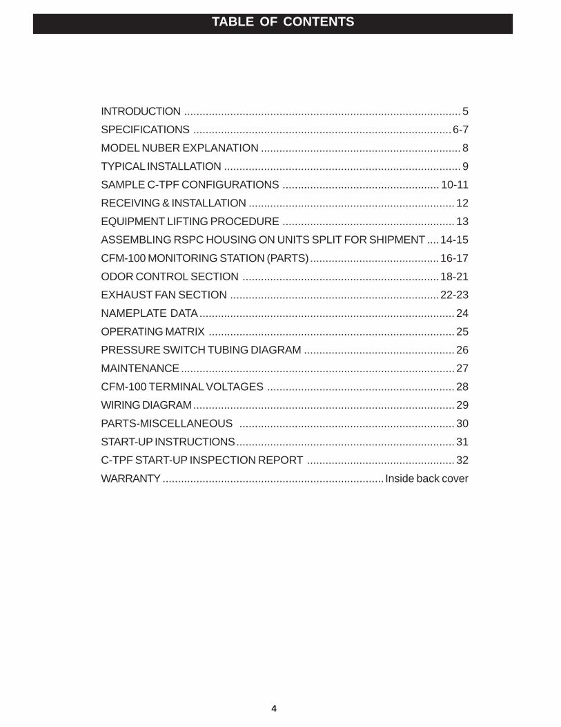
INTRODUCTION .......................................................................................... 5SPECIFICATIONS ....................................................................................6-7
MODEL NUBER EXPLANATION ................................................................. 8
TYPICAL INSTALLATION ............................................................................. 9SAMPLE C-TPF CONFIGURATIONS ................................................... 10-11
RECEIVING & INSTALLATION ................................................................... 12
EQUIPMENT LIFTING PROCEDURE ........................................................ 13ASSEMBLING RSPC HOUSING ON UNITS SPLIT FOR SHIPMENT ....14-15
CFM-100 MONITORING STATION (PARTS)..........................................16-17
ODOR CONTROL SECTION ................................................................18-21EXHAUST FAN SECTION ....................................................................22-23
NAMEPLATE DATA................................................................................... 24
OPERATING MATRIX ................................................................................ 25PRESSURE SWITCH TUBING DIAGRAM ................................................. 26
MAINTENANCE ......................................................................................... 27
CFM-100 TERMINAL VOLTAGES ............................................................. 28WIRING DIAGRAM..................................................................................... 29
PARTS-MISCELLANEOUS ...................................................................... 30
START-UP INSTRUCTIONS....................................................................... 31C-TPF START-UP INSPECTION REPORT ................................................ 32
WARRANTY ........................................................................ Inside back cover
TABLE OF CONTENTS
5
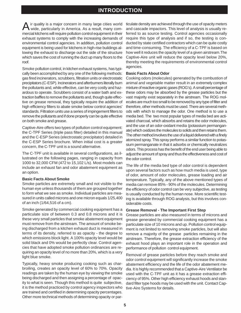
Air quality is a major concern in many large cities world wide, particularly in America. As a result, many com-
mercial kitchens will require pollution control equipment in theirexhaust systems to comply with the increasing demands ofenvironmental control agencies. In addition, pollution controlequipment is being used for kitchens in high-rise buildings al-lowing the exhaust to discharge out the side of the structurewhich saves the cost of running the duct up many floors to theroof.
Smoke pollution control, in kitchen exhaust systems, has typi-cally been accomplished by any one of the following methods:gas fired incinerators, scrubbers, filtration units or electrostaticprecipitators (C-ESP). Incinerators and afterburners literally burnthe pollutants and, while effective, can be very costly and haz-ardous to operate. Scrubbers consist of a water bath and ex-traction baffles to remove the pollutants and, though quite effec-tive on grease removal, they typically require the addition ofhigh efficiency filters to abate smoke below control agencies’standards. Filtration units use a series of impingement filters toremove the pollutants and if done properly can be quite effectiveon both smoke and grease.
Captive-Aire offers two types of pollution control equipment:the C-TPF Series (triple pass filter) detailed in this manualand the C-ESP Series (electrostatic precipitator) detailed inthe C-ESP Series brochure. When initial cost is a greaterconcern, the C-TPF unit is a sound alternative.
The C-TPF unit is available in several configurations, as il-lustrated on the following pages, ranging in capacity from1000 to 32,000 CFM (472 to 15,102 L/s). Most models caninclude an exhaust fan and odor abatement equipment asan option.
Basic Facts About SmokeSmoke particles are extremely small and not visible to thehuman eye unless thousands of them are grouped togetherto form what we see as smoke. Individual particles are mea-sured in units called microns and one micron equals 1/25,400of an inch (1/64,516 of a cm).
Smoke generated by commercial cooking equipment has aparticulate size of between 0.3 and 0.8 microns and it isthese very small particles that smoke abatement equipmentmust remove from the airstream. The amount of smoke be-ing discharged from a kitchen exhaust duct is measured interms of its density, referred to as opacity - the degree towhich emissions block light. A 100% opacity level would besolid black and 0% would be perfectly clear. Control agen-cies that have adopted smoke pollution ordinances are re-quiring an opacity level of no more than 20%, which is a verylight blue smoke.
Typically, heavy smoke producing cooking such as char-broiling, creates an opacity level of 60% to 70%. Opacityreadings are taken by the human eye by viewing the smokebeing discharged and then assigning a percentage of opac-ity to what is seen. Though this method is quite subjective,it is the method practiced by control agency inspectors whoare trained and certified in determining opacity percentages.Other more technical methods of determining opacity or par-
ticulate density are achieved through the use of opacity metersand cascade impactors. This level of analysis is usually re-ferred to as source testing. Control agencies occasionallyrequire this type of analysis and if so, the testing is con-ducted by state certified contractors which can be quite costlyand time-consuming. The efficiency of a C-TPF is based onhow well it reduces the opacity level of a given airstream.TheCaptive-Aire unit will reduce the opacity level below 20%,thereby meeting the requirements of environmental controlagencies.
Basic Facts About OdorCooking odors (molecules) generated by the combustion ofanimal and vegetable matter result in an extremely complexmixture of reactive organic gases (ROG’s). A small percentage ofthese odors may be absorbed by the grease particles but thevast majority exist separately in the airstream. The ROG mol-ecules are much too small to be removed by any type of filter andtherefore, other methods must be used. There are several meth-ods with which to manage the odor. One method is to use amedia bed. The two most popular types of media bed are acti-vated charcoal, which absorbs and retains the odor molecules,and the use of an odor-oxidant media (potassium permangan-ate) which oxidizes the molecules to solids and then retains them.The other method involves the use of a liquid delivered with a finelyatomized spray. This spray performs a similar function to potas-sium permanganate in that it adsorbs or chemically neutralizesodors. This process has the benefit of the end user being able toadjust the amount of spray and thus the effectiveness and cost ofthe odor control.
The life of the media bed type of odor control is dependentupon several factors such as how much media is used, typeof odor, amount of odor molecules, grease loading and airtemperature. Typically, any of the above mentioned types ofmedia can remove 85% - 90% of the molecules. Determiningthe efficiency of odor control can be very subjective, as testingis usually conducted by the human nose. More scientific test-ing is available through ROG analysis, but this involves con-siderable costs.
Grease Removal - The Important First StepGrease particles are also measured in terms of microns andgrease generated by commercial cooking equipment has aparticulate size of 10 microns and up. Pollution control equip-ment is not limited to removing smoke particles, but will alsoremove a majority of the grease particles remaining in theairstream. Therefore, the grease extraction efficiency of theexhaust hood plays an important role in the operation andperformance of pollution control equipment.
Removal of grease particles before they reach smoke andodor control equipment will significantly increase the smokeabatement efficiency and the life of the odor abatement me-dia. It is highly recommended that a Captive-Aire Ventilator beused with the C-TPF unit as it has a grease extraction effi-ciency of 95%. Other high efficiency exhaust hoods and stan-dard filter type hoods may be used with the unit. Contact Cap-tive-Aire Systems for details.
INTRODUCTION
6
SPECIFICATIONS
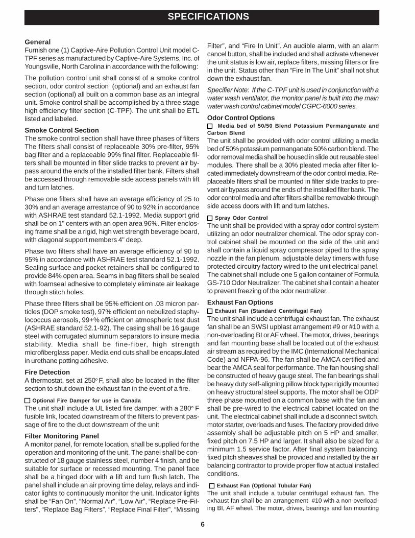
GeneralFurnish one (1) Captive-Aire Pollution Control Unit model C-TPF series as manufactured by Captive-Aire Systems, Inc. ofYoungsville, North Carolina in accordance with the following:
The pollution control unit shall consist of a smoke controlsection, odor control section (optional) and an exhaust fansection (optional) all built on a common base as an integralunit. Smoke control shall be accomplished by a three stagehigh efficiency filter section (C-TPF). The unit shall be ETLlisted and labeled.
Smoke Control SectionThe smoke control section shall have three phases of filtersThe filters shall consist of replaceable 30% pre-filter, 95%bag filter and a replaceable 99% final filter. Replaceable fil-ters shall be mounted in filter slide tracks to prevent air by-pass around the ends of the installed filter bank. Filters shallbe accessed through removable side access panels with liftand turn latches.
Phase one filters shall have an average efficiency of 25 to30% and an average arrestance of 90 to 92% in accordancewith ASHRAE test standard 52.1-1992. Media support gridshall be on 1" centers with an open area 96%. Filter enclos-ing frame shall be a rigid, high wet strength beverage board,with diagonal support members 4" deep.
Phase two filters shall have an average efficiency of 90 to95% in accordance with ASHRAE test standard 52.1-1992.Sealing surface and pocket retainers shall be configured toprovide 84% open area. Seams in bag filters shall be sealedwith foamseal adhesive to completely eliminate air leakagethrough stitch holes.
Phase three filters shall be 95% efficient on .03 micron par-ticles (DOP smoke test), 97% efficient on nebulized staphy-lococcus aerosols, 99+% efficient on atmospheric test dust(ASHRAE standard 52.1-92). The casing shall be 16 gaugesteel with corrugated aluminum separators to insure mediastability. Media shall be fine-fiber, high strengthmicrofiberglass paper. Media end cuts shall be encapsulatedin urethane potting adhesive.
Fire DetectionA thermostat, set at 250o F, shall also be located in the filtersection to shut down the exhaust fan in the event of a fire.
Optional Fire Damper for use in CanadaThe unit shall include a UL listed fire damper, with a 280o Ffusible link, located downstream of the filters to prevent pas-sage of fire to the duct downstream of the unit
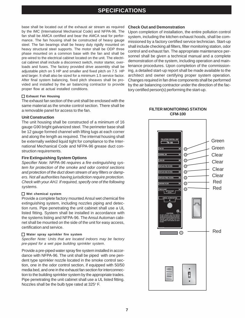
Filter Monitoring PanelA monitor panel, for remote location, shall be supplied for theoperation and monitoring of the unit. The panel shall be con-structed of 18 gauge stainless steel, number 4 finish, and besuitable for surface or recessed mounting. The panel faceshall be a hinged door with a lift and turn flush latch. Thepanel shall include an air proving time delay, relays and indi-cator lights to continuously monitor the unit. Indicator lightsshall be “Fan On”, “Normal Air”, “Low Air”, “Replace Pre-Fil-ters”, “Replace Bag Filters”, “Replace Final Filter”, “Missing
Filter”, and “Fire In Unit”. An audible alarm, with an alarmcancel button, shall be included and shall activate wheneverthe unit status is low air, replace filters, missing filters or firein the unit. Status other than “Fire In The Unit” shall not shutdown the exhaust fan.
Specifier Note: If the C-TPF unit is used in conjunction with awater wash ventilator, the monitor panel is built into the mainwater wash control cabinet model CGPC-6000 series.
Odor Control Options Media bed of 50/50 Blend Potassium Permanganate and
Carbon BlendThe unit shall be provided with odor control utilizing a mediabed of 50% potassium permanganate 50% carbon blend. Theodor removal media shall be housed in slide out reusable steelmodules. There shall be a 30% pleated media after filter lo-cated immediately downstream of the odor control media. Re-placeable filters shall be mounted in filter slide tracks to pre-vent air bypass around the ends of the installed filter bank. Theodor control media and after filters shall be removable throughside access doors with lift and turn latches.
Spray Odor ControlThe unit shall be provided with a spray odor control systemutilizing an odor neutralizer chemical. The odor spray con-trol cabinet shall be mounted on the side of the unit andshall contain a liquid spray compressor piped to the spraynozzle in the fan plenum, adjustable delay timers with fuseprotected circuitry factory wired to the unit electrical panel.The cabinet shall include one 5 gallon container of FormulaGS-710 Odor Neutralizer. The cabinet shall contain a heaterto prevent freezing of the odor neutralizer.
Exhaust Fan Options Exhaust Fan (Standard Centrifugal Fan)
The unit shall include a centrifugal exhaust fan. The exhaustfan shall be an SWSI upblast arrangement #9 or #10 with anon-overloading BI or AF wheel. The motor, drives, bearingsand fan mounting base shall be located out of the exhaustair stream as required by the IMC (International MechanicalCode) and NFPA-96. The fan shall be AMCA certified andbear the AMCA seal for performance. The fan housing shallbe constructed of heavy gauge steel. The fan bearings shallbe heavy duty self-aligning pillow block type rigidly mountedon heavy structural steel supports. The motor shall be ODPthree phase mounted on a common base with the fan andshall be pre-wired to the electrical cabinet located on theunit. The electrical cabinet shall include a disconnect switch,motor starter, overloads and fuses. The factory provided driveassembly shall be adjustable pitch on 5 HP and smaller,fixed pitch on 7.5 HP and larger. It shall also be sized for aminimum 1.5 service factor. After final system balancing,fixed pitch sheaves shall be provided and installed by the airbalancing contractor to provide proper flow at actual installedconditions.
Exhaust Fan (Optional Tubular Fan)The unit shall include a tubular centrifugal exhaust fan. Theexhaust fan shall be an arrangement #10 with a non-overload-ing BI, AF wheel. The motor, drives, bearings and fan mounting
7
SPECIFICATIONS
FILTER MONITORING STATIONCFM-100
base shall be located out of the exhaust air stream as requiredby the IMC (International Mechanical Code) and NFPA-96. Thefan shall be AMCA certified and bear the AMCA seal for perfor-mance. The fan housing shall be constructed of heavy gaugesteel. The fan bearings shall be heavy duty rigidly mounted onheavy structural steel supports. The motor shall be ODP threephase mounted on a common base with the fan and shall bepre-wired to the electrical cabinet located on the unit. The electri-cal cabinet shall include a disconnect switch, motor starter, over-loads and fuses. The factory provided drive assembly shall beadjustable pitch on 5 HP and smaller and fixed pitch on 7.5 HPand larger. It shall also be sized for a minimum 1.5 service factor.After final system balancing, fixed pitch sheaves shall be pro-vided and installed by the air balancing contractor to provideproper flow at actual installed conditions.
Exhaust Fan HousingThe exhaust fan section of the unit shall be enclosed with thesame material as the smoke control section. There shall bea removable panel for access to the fan.
Unit ConstructionThe unit housing shall be constructed of a minimum of 16gauge G90 bright galvanized steel. The perimeter base shallbe 12 gauge formed channel with lifting lugs at each cornerand along the length as required. The internal housing shallbe externally welded liquid tight for compliance to the Inter-national Mechanical Code and NFPA-96 grease duct con-struction requirements.
Fire Extinguishing System OptionsSpecifier Note: NFPA-96 requires a fire extinguishing sys-tem for protection of the smoke and odor control sectionsand protection of the duct down stream of any filters or damp-ers. Not all authorities having jurisdiction require protection.Check with your AHJ. If required, specify one of the followingsystems.
Wet chemical systemProvide a complete factory mounted Ansul wet chemical fireextinguishing system, including nozzles piping and detec-tion runs. Pipe penetrating the unit cabinet shall use a ULlisted fitting. System shall be installed in accordance withthe systems listing and NFPA-96. The Ansul Automan cabi-net shall be mounted on the side of the unit for easy access,certification and service.
Water spray sprinkler fire systemSpecifier Note: Units that are located indoors may be factorypre-piped for a wet pipe building sprinkler system.
Provide a pre-piped water spray fire system installed in accor-dance with NFPA-96. The unit shall be piped with one pen-dent type sprinkler nozzle located in the smoke control sec-tion, one in the odor control section, if equipped with 50/50media bed, and one in the exhaust fan section for interconnec-tion to the building sprinkler system by the appropriate trades.Pipe penetrating the unit cabinet shall use a UL listed fitting.Nozzles shall be the bulb type rated at 325o F.
Check Out and DemonstrationUpon completion of installation, the entire pollution controlsystem, including the kitchen exhaust hoods, shall be com-missioned by a factory certified service technician. Start-upshall include checking all filters, filter monitoring station, odorcontrol and exhaust fan. The appropriate maintenance per-sonnel shall be given a technical manual and a completedemonstration of the system, including operation and main-tenance procedures. Upon completion of the commission-ing, a detailed start-up report shall be made available to thearchitect and owner certifying proper system operation.Changes required in fan drive components shall be performedby the air balancing contractor under the direction of the fac-tory certified person(s) performing the start-up.
GreenGreenClearClearClearClearRedRed
Red
8
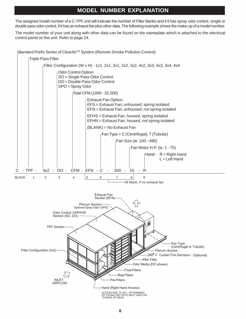
The assigned model number of a C-TPF unit will indicate the number of Filter Banks and if it has spray odor control, single ordouble pass odor control, if it has an exhaust fan plus other data. The following example shows the make-up of a model number.
The model number of your unit along with other data can be found on the nameplate which is attached to the electricalcontrol panel on the unit. Refer to page 24.
MODEL NUMBER EXPLANATION
All Blank, if no exhaust fan
Standard Prefix Series of ClearAirTM System (Remote Smoke Pollution Control)
Triple Pass Filter
Filter Configuration (W x H) - 1x1, 2x1, 3x1, 2x2, 3x2, 4x2, 3x3, 4x3, 3x4, 4x4
Odor Control Option:SO = Single Pass Odor ControlDO = Double Pass Odor ControlSPO = Spray Odor
Total CFM (1000 - 32,000)
Exhaust Fan Option:EFS = Exhaust Fan, unhoused, spring isolatedEFN = Exhaust Fan, unhoused, not spring isolated
EFHS = Exhaust Fan, housed, spring isolatedEFHN = Exhaust Fan, housed, not spring isolated
(BLANK) = No Exhaust Fan
Fan Type = C (Centrifugal), T (Tubular)
Fan Size (ie. 100 - 490)
Fan Motor H.P. (ie. 1 - 75)
Hand - R = Right HandL = Left Hand
C - TPF - 3x2 - DO - CFM - EFN - C - 300 - 15 - R
BLOCK 1 2 3 4 5 6 7 8 9
9
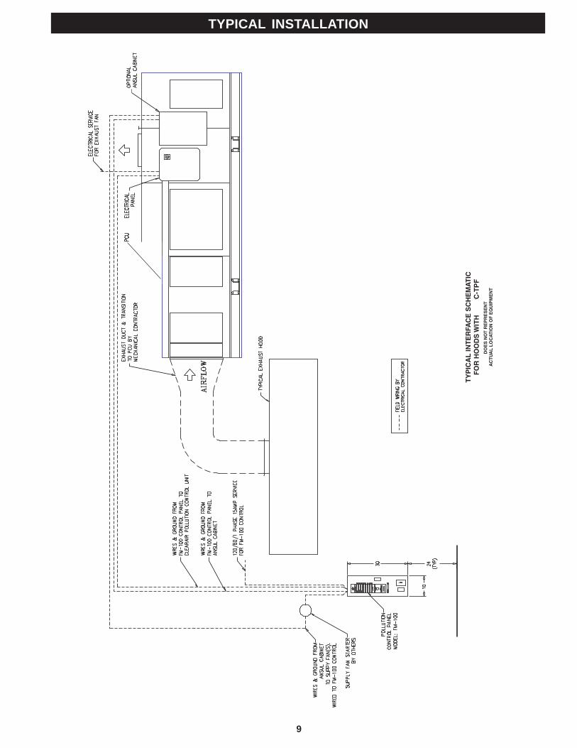
TYPICAL INSTALLATION
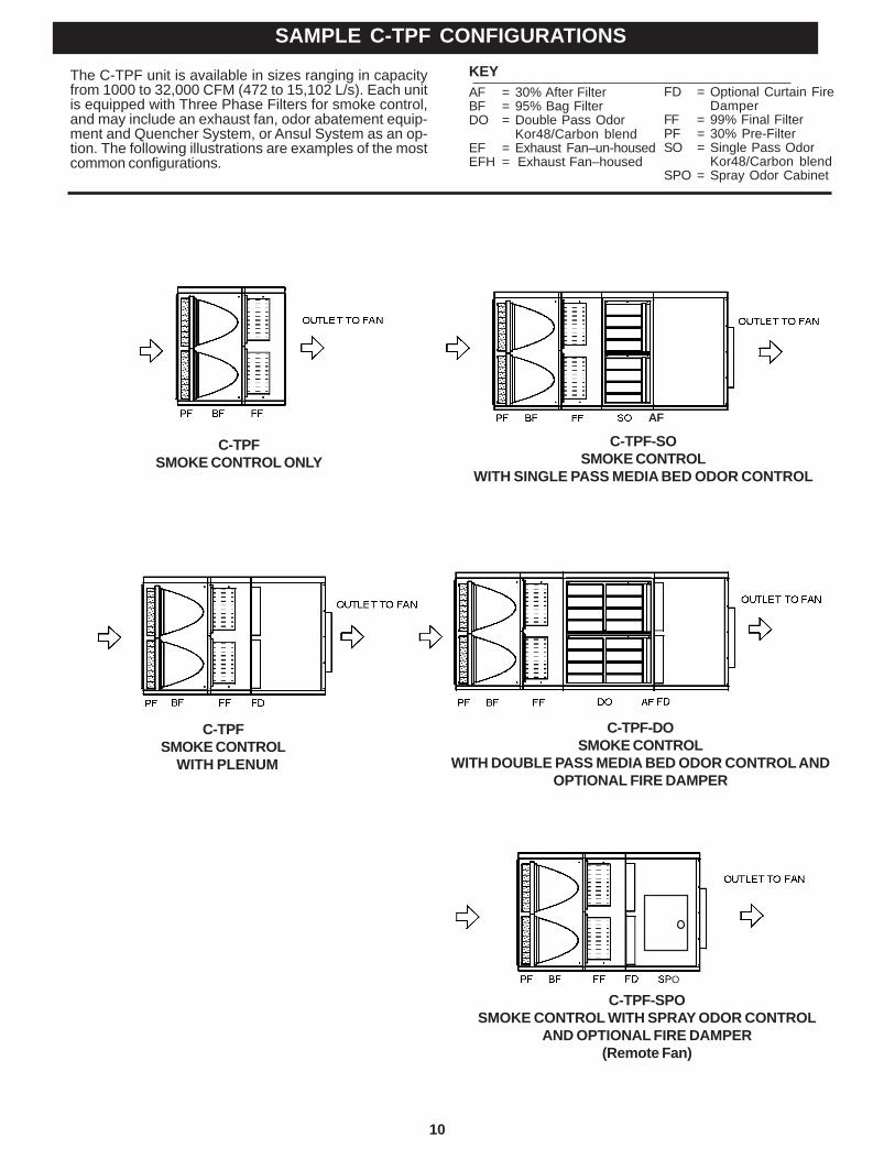
10
KEYAF = 30% After FilterBF = 95% Bag FilterDO = Double Pass Odor
Kor48/Carbon blendEF = Exhaust Fan–un-housedEFH = Exhaust Fan–housed
FD = Optional Curtain FireDamper
FF = 99% Final FilterPF = 30% Pre-FilterSO = Single Pass Odor
Kor48/Carbon blendSPO = Spray Odor Cabinet
SAMPLE C-TPF CONFIGURATIONS
The C-TPF unit is available in sizes ranging in capacityfrom 1000 to 32,000 CFM (472 to 15,102 L/s). Each unitis equipped with Three Phase Filters for smoke control,and may include an exhaust fan, odor abatement equip-ment and Quencher System, or Ansul System as an op-tion. The following illustrations are examples of the mostcommon configurations.
C-TPFSMOKE CONTROL ONLY
C-TPF-SOSMOKE CONTROL
WITH SINGLE PASS MEDIA BED ODOR CONTROL
C-TPFSMOKE CONTROL WITH PLENUM
C-TPF-DOSMOKE CONTROL
WITH DOUBLE PASS MEDIA BED ODOR CONTROL ANDOPTIONAL FIRE DAMPER
C-TPF-SPOSMOKE CONTROL WITH SPRAY ODOR CONTROL
AND OPTIONAL FIRE DAMPER(Remote Fan)
O
AF
11
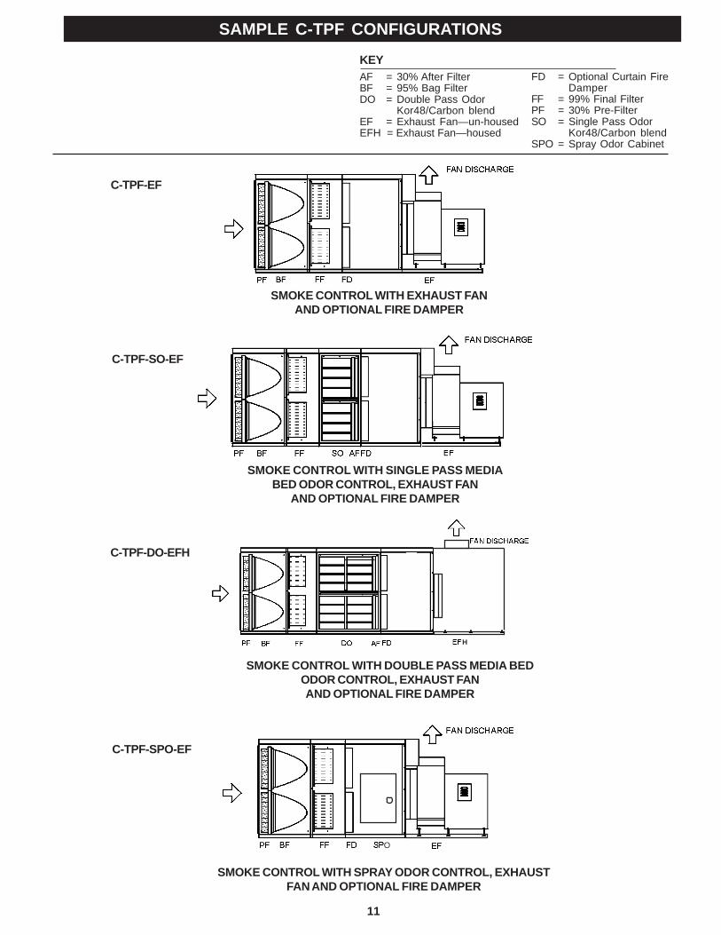
KEYAF = 30% After FilterBF = 95% Bag FilterDO = Double Pass Odor
Kor48/Carbon blendEF = Exhaust Fan—un-housedEFH = Exhaust Fan—housed
FD = Optional Curtain FireDamper
FF = 99% Final FilterPF = 30% Pre-FilterSO = Single Pass Odor
Kor48/Carbon blendSPO = Spray Odor Cabinet
SMOKE CONTROL WITH SPRAY ODOR CONTROL, EXHAUSTFAN AND OPTIONAL FIRE DAMPER
SAMPLE C-TPF CONFIGURATIONS
SMOKE CONTROL WITH SINGLE PASS MEDIABED ODOR CONTROL, EXHAUST FAN
AND OPTIONAL FIRE DAMPER
SMOKE CONTROL WITH DOUBLE PASS MEDIA BEDODOR CONTROL, EXHAUST FANAND OPTIONAL FIRE DAMPER
SMOKE CONTROL WITH EXHAUST FANAND OPTIONAL FIRE DAMPER
O
C-TPF-SPO-EF
C-TPF-DO-EFH
C-TPF-SO-EF
C-TPF-EF
H
12
RECEIVINGMost C-TPF units are shipped in one piece. However, someunits, because of size or special jobsite conditions, may beshipped in multiple sections. Follow the instructions pro-vided with the unit to join sections back together. If the unitincludes media bed odor control, the KOR48/carbon odor con-trol media is packaged separately. Verify against the ship-ping documents that you have received all items and noteany shipping damage, obvious or hidden, to your carrier andon your Bill of Lading. If damage is found, immediately file aclaim with the transport company. All units are thoroughlyinspected and fully operation tested at the factory prior toshipment.
Verify that the electrical and air flow ratings on the unit nameplate agrees with jobsite requirements. If a contradiction arisesnotify the factory prior to proceeding with installation.SAFETY CONSIDERATIONSInstalling and servicing the unit can be hazardous due to thepresence of electrical components. Only trained and quali-fied service personnel should install or service this equipment.
Untrained personnel can perform basic maintenance, suchas cleaning and replacing filters. All other operations shouldbe performed by trained service personnel. When installing orservicing, observe precautions in literature and on tags andlabels attached to unit.
Follow all safety codes. Wear safety glasses and work gloves.Use quenching cloth for brazing operations. Have fire extin-guisher available. Read these instructions thoroughly.
WARNINGBefore installing or servicing system, always turn off mainpower to system. There may be more than one disconnectswitch. Electrical shock can cause personal injury or death.
RIGGINGAll units are provided with a minimum of four (4) lifting pointsfor rigging attachment. WARNING: Use all lifting points pro-vided. (Refer to Page 13) Spreader bars are mandatory toprevent contact and damage to the unit by lifting hooks, straps,cables, or chains. Consult the mechanical or structural engi-neer before moving the unit across the roof deck.
INSTALLATION CODESThis unit requires external plumbing and electrical connectionsto be made in the field. It is recommended that the AuthorityHaving Jurisdiction (AHJ) be consulted regarding local codesand installation procedures. Captive-Aire Systems is not re-sponsible for obtaining necessary approvals and permits whichmay be required for installation, nor is it responsible for verifyingthat the unit has been installed in accordance with national,state, and local codes. In the absence of locally adopted codesuse the latest editions of the national electrical code and theuniform mechanical code. Connections of the exhaust duct tothe inlet and outlet of the C-TPF unit must be fully welded tocomply with NFPA-96.
INSTALLATION PRECAUTIONS1. The services of qualified contractors are essential for safeand proper installation of this equipment.
2. The air volumes and external static pressures that arelisted on the unit are for the middle of the operating range ofthe filters. The initial air volume should be at least 10% higherthan the listed CFM. As the filters load up the air volume willdrop. This is inherent to this type of unit. If the unit is set upat or below the design CFM, as the filters load up, the kitchenhood may experience smoke loss problems. Please consultthe factory if you have questions.
3. The unit is designed for installation on a level surface.
4. When installed in an enclosed space a fire rated enclo-sure may be required for the unit and associated duct work.Consult the Authority Having Jurisdiction.
5. Consult the Authority Having Jurisdiction regarding re-quirements covering the point of termination of the exhaustoutlet of this unit. Minimum distances must usually bemaintained between the exhaust outlet and any outside airintakes and/or adjacent structures or property lines.
6. Do not apply power to the unit until all electrical con-nections have been made and a pre-start-up preliminary in-spection has been completed.
7. Allow a minimum of 36 inches clearance in front of thefilter access door and electrical compartment door for ser-vice and routine maintenance.
SHORT TERM STORAGEUnits that include media bed odor control are provided withKOR48/carbon media which is shipped separate from theunit. KOR48/carbon media must be stored in a dry placewith less than 95% relative humidity.
LONG TERM STORAGE (OVER ONE MONTH)If the unit is equipped with an exhaust fan it must be re-lubricated as soon as it arrives. To prevent corrosion all bear-ings should receive grease and be rotated the first of everymonth. Turn the wheel by hand while greasing bearings. Aclean 1/16" bead of grease must appear on each side of eachbearing. Refer to specific bearing lubricating instructions onthe fan. Also, refer to bearing lubricating instructions found inthe exhaust fan section of this manual.
Bearings which are to be stored or idle for an extended pe-riod of time should be wrapped in a neutral grease-proof pa-per, foil, or plastic film. Compounds can be ecommended bythe bearing manufacturer to provide protection for severalmonths to several years.After long-term storage, grease should be purged from the
RECEIVING & INSTALLATION
13
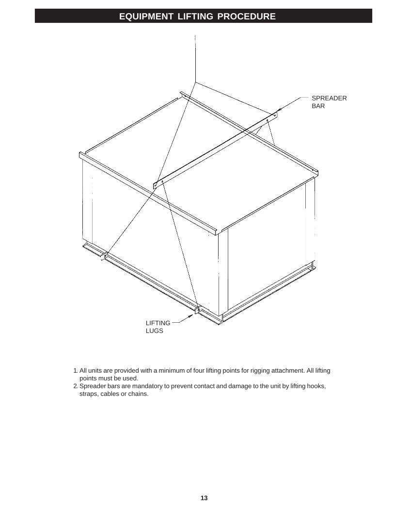
EQUIPMENT LIFTING PROCEDURE
SPREADERBAR
LIFTINGLUGS
1. All units are provided with a minimum of four lifting points for rigging attachment. All liftingpoints must be used.
2. Spreader bars are mandatory to prevent contact and damage to the unit by lifting hooks,straps, cables or chains.
14
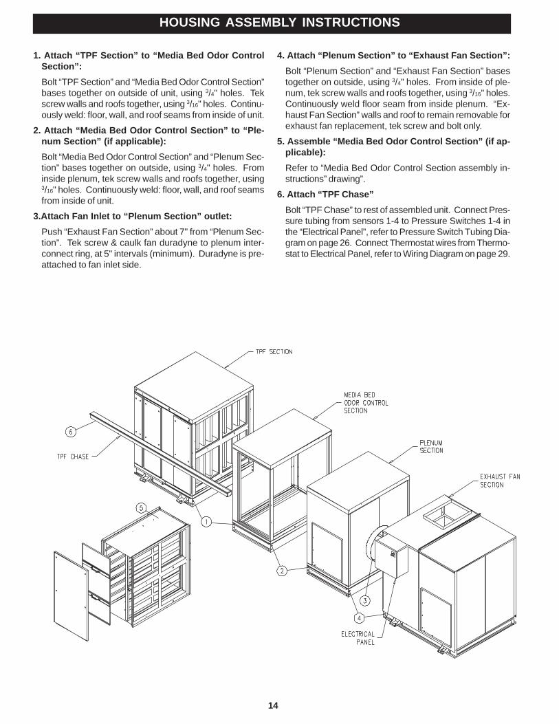
HOUSING ASSEMBLY INSTRUCTIONS
1. Attach “TPF Section” to “Media Bed Odor ControlSection”:Bolt “TPF Section” and “Media Bed Odor Control Section”bases together on outside of unit, using 3/4" holes. Tekscrew walls and roofs together, using 3/16" holes. Continu-ously weld: floor, wall, and roof seams from inside of unit.
2. Attach “Media Bed Odor Control Section” to “Ple-num Section” (if applicable):Bolt “Media Bed Odor Control Section” and “Plenum Sec-tion” bases together on outside, using 3/4" holes. Frominside plenum, tek screw walls and roofs together, using3/16" holes. Continuously weld: floor, wall, and roof seamsfrom inside of unit.
3.Attach Fan Inlet to “Plenum Section” outlet:Push “Exhaust Fan Section” about 7" from “Plenum Sec-tion”. Tek screw & caulk fan duradyne to plenum inter-connect ring, at 5" intervals (minimum). Duradyne is pre-attached to fan inlet side.
4. Attach “Plenum Section” to “Exhaust Fan Section”:Bolt “Plenum Section” and “Exhaust Fan Section” basestogether on outside, using 3/4" holes. From inside of ple-num, tek screw walls and roofs together, using 3/16" holes.Continuously weld floor seam from inside plenum. “Ex-haust Fan Section” walls and roof to remain removable forexhaust fan replacement, tek screw and bolt only.
5. Assemble “Media Bed Odor Control Section” (if ap-plicable):Refer to “Media Bed Odor Control Section assembly in-structions” drawing”.
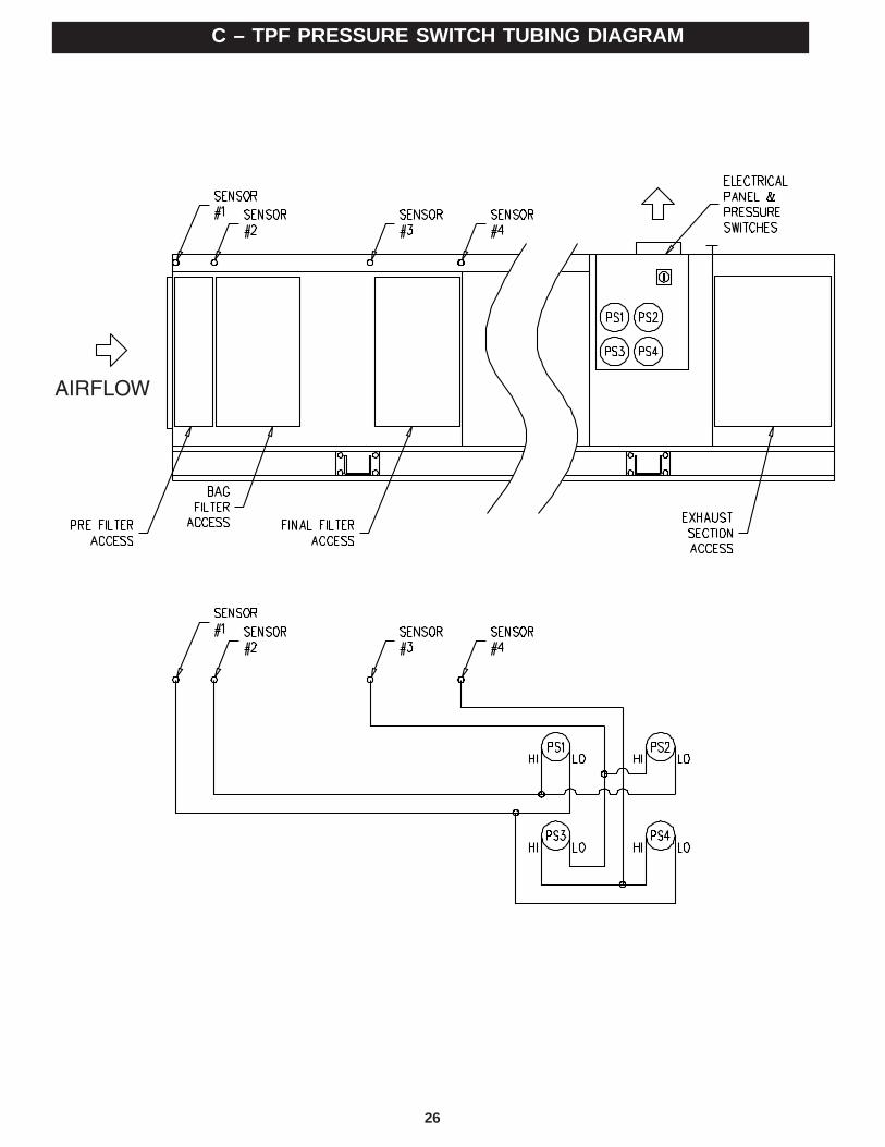
6. Attach “TPF Chase”Bolt “TPF Chase” to rest of assembled unit. Connect Pres-sure tubing from sensors 1-4 to Pressure Switches 1-4 inthe “Electrical Panel”, refer to Pressure Switch Tubing Dia-gram on page 26. Connect Thermostat wires from Thermo-stat to Electrical Panel, refer to Wiring Diagram on page 29.
15
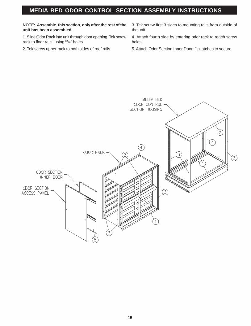
MEDIA BED ODOR CONTROL SECTION ASSEMBLY INSTRUCTIONS
NOTE: Assemble this section, only after the rest of theunit has been assembled.1. Slide Odor Rack into unit through door opening. Tek screwrack to floor rails, using 3/16" holes.
2. Tek screw upper rack to both sides of roof rails.
3. Tek screw first 3 sides to mounting rails from outside ofthe unit.
4. Attach fourth side by entering odor rack to reach screwholes.
5. Attach Odor Section Inner Door, flip latches to secure.
16
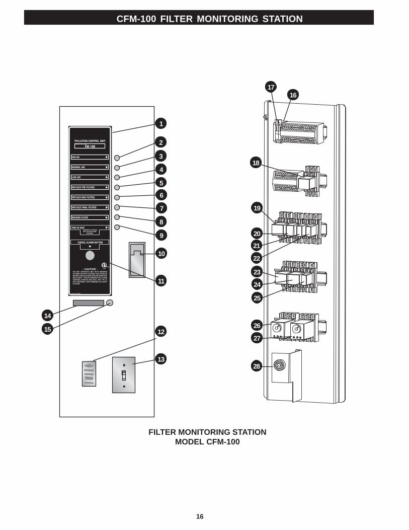
CFM-100 FILTER MONITORING STATION
1716
18
19
20
21
22
23
24
25
26
27
28
1
2
11
10
9
8
7
6
5
4
3
12
13
14
15
FILTER MONITORING STATIONMODEL CFM-100
17
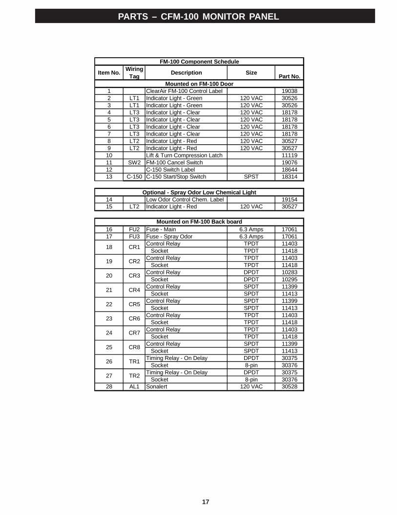
PARTS – CFM-100 MONITOR PANEL
Item No. WiringTag Description Size Gaylord
Part No.
1 ClearAir FM-100 Control Label 190382 LT1 Indicator Light - Green 120 VAC 305263 LT1 Indicator Light - Green 120 VAC 305264 LT3 Indicator Light - Clear 120 VAC 181785 LT3 Indicator Light - Clear 120 VAC 181786 LT3 Indicator Light - Clear 120 VAC 181787 LT3 Indicator Light - Clear 120 VAC 181788 LT2 Indicator Light - Red 120 VAC 305279 LT2 Indicator Light - Red 120 VAC 3052710 Lift & Turn Compression Latch 1111911 SW2 FM-100 Cancel Switch 1907612 C-150 Switch Label 1864413 C-150 C-150 Start/Stop Switch SPST 18314
14 Low Odor Control Chem. Label 1915415 LT2 Indicator Light - Red 120 VAC 30527
16 FU2 Fuse - Main 6.3 Amps 1706117 FU3 Fuse - Spray Odor 6.3 Amps 17061
Control Relay TPDT 11403 Socket TPDT 11418Control Relay TPDT 11403 Socket TPDT 11418Control Relay DPDT 10283 Socket DPDT 10295Control Relay SPDT 11399 Socket SPDT 11413Control Relay SPDT 11399 Socket SPDT 11413Control Relay TPDT 11403 Socket TPDT 11418Control Relay TPDT 11403 Socket TPDT 11418Control Relay SPDT 11399 Socket SPDT 11413Timing Relay - On Delay DPDT 30375 Socket 8-pin 30376Timing Relay - On Delay DPDT 30375 Socket 8-pin 30376
28 AL1 Sonalert 120 VAC 30528
18
19
FM-100 Component Schedule
20
CR1
CR2
Optional - Spray Odor Low Chemical Light
Mounted on FM-100 Door
Mounted on FM-100 Back board
CR3
26
CR7
27
CR8
TR1
TR2
24
CR4
CR5
CR6
25
23
21
22
18
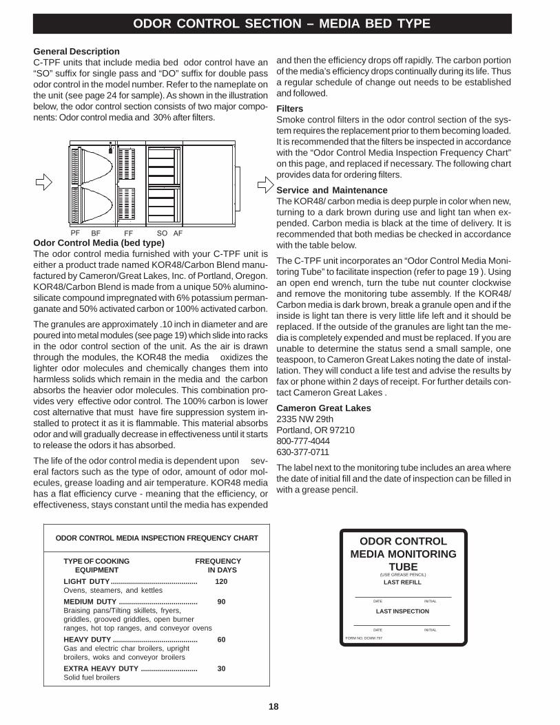
General DescriptionC-TPF units that include media bed odor control have an“SO” suffix for single pass and “DO” suffix for double passodor control in the model number. Refer to the nameplate onthe unit (see page 24 for sample). As shown in the illustrationbelow, the odor control section consists of two major compo-nents: Odor control media and 30% after filters.
Odor Control Media (bed type)The odor control media furnished with your C-TPF unit iseither a product trade named KOR48/Carbon Blend manu-factured by Cameron/Great Lakes, Inc. of Portland, Oregon.KOR48/Carbon Blend is made from a unique 50% alumino-silicate compound impregnated with 6% potassium perman-ganate and 50% activated carbon or 100% activated carbon.
The granules are approximately .10 inch in diameter and arepoured into metal modules (see page 19) which slide into racksin the odor control section of the unit. As the air is drawnthrough the modules, the KOR48 the media oxidizes thelighter odor molecules and chemically changes them intoharmless solids which remain in the media and the carbonabsorbs the heavier odor molecules. This combination pro-vides very effective odor control. The 100% carbon is lowercost alternative that must have fire suppression system in-stalled to protect it as it is flammable. This material absorbsodor and will gradually decrease in effectiveness until it startsto release the odors it has absorbed.
The life of the odor control media is dependent upon sev-eral factors such as the type of odor, amount of odor mol-ecules, grease loading and air temperature. KOR48 mediahas a flat efficiency curve - meaning that the efficiency, oreffectiveness, stays constant until the media has expended
and then the efficiency drops off rapidly. The carbon portionof the media’s efficiency drops continually during its life. Thusa regular schedule of change out needs to be establishedand followed.
FiltersSmoke control filters in the odor control section of the sys-tem requires the replacement prior to them becoming loaded.It is recommended that the filters be inspected in accordancewith the “Odor Control Media Inspection Frequency Chart”on this page, and replaced if necessary. The following chartprovides data for ordering filters.
Service and MaintenanceThe KOR48/ carbon media is deep purple in color when new,turning to a dark brown during use and light tan when ex-pended. Carbon media is black at the time of delivery. It isrecommended that both medias be checked in accordancewith the table below.
The C-TPF unit incorporates an “Odor Control Media Moni-toring Tube” to facilitate inspection (refer to page 19 ). Usingan open end wrench, turn the tube nut counter clockwiseand remove the monitoring tube assembly. If the KOR48/Carbon media is dark brown, break a granule open and if theinside is light tan there is very little life left and it should bereplaced. If the outside of the granules are light tan the me-dia is completely expended and must be replaced. If you areunable to determine the status send a small sample, oneteaspoon, to Cameron Great Lakes noting the date of instal-lation. They will conduct a life test and advise the results byfax or phone within 2 days of receipt. For further details con-tact Cameron Great Lakes .
Cameron Great Lakes2335 NW 29thPortland, OR 97210800-777-4044630-377-0711
The label next to the monitoring tube includes an area wherethe date of initial fill and the date of inspection can be filled inwith a grease pencil.
ODOR CONTROLMEDIA MONITORING
TUBELAST REFILL
LAST INSPECTION
FORM NO. OCMM 797
DATE INITIAL
DATE INITIAL
(USE GREASE PENCIL)
ODOR CONTROL SECTION – MEDIA BED TYPE
TYPE OF COOKING FREQUENCY EQUIPMENT IN DAYSLIGHT DUTY ........................................... 120Ovens, steamers, and kettlesMEDIUM DUTY ....................................... 90Braising pans/Tilting skillets, fryers,griddles, grooved griddles, open burnerranges, hot top ranges, and conveyor ovensHEAVY DUTY .......................................... 60Gas and electric char broilers, uprightbroilers, woks and conveyor broilersEXTRA HEAVY DUTY ............................ 30Solid fuel broilers
TRAHCYCNEUQERFNOITCEPSNIAIDEMLORTNOCRODO
19
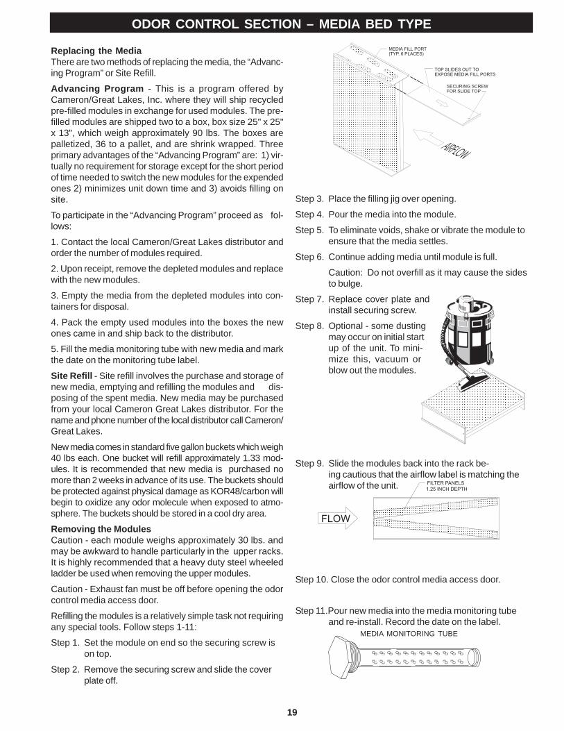
Step 3. Place the filling jig over opening.
Step 4. Pour the media into the module.
Step 5. To eliminate voids, shake or vibrate the module toensure that the media settles.
Step 6. Continue adding media until module is full.
Caution: Do not overfill as it may cause the sidesto bulge.
Step 7. Replace cover plate andinstall securing screw.
Step 8. Optional - some dustingmay occur on initial startup of the unit. To mini-mize this, vacuum orblow out the modules.
Step 9. Slide the modules back into the rack be-ing cautious that the airflow label is matching theairflow of the unit.
Step 10. Close the odor control media access door.
Step 11.Pour new media into the media monitoring tubeand re-install. Record the date on the label.
Replacing the MediaThere are two methods of replacing the media, the “Advanc-ing Program” or Site Refill.
Advancing Program - This is a program offered byCameron/Great Lakes, Inc. where they will ship recycledpre-filled modules in exchange for used modules. The pre-filled modules are shipped two to a box, box size 25" x 25"x 13", which weigh approximately 90 lbs. The boxes arepalletized, 36 to a pallet, and are shrink wrapped. Threeprimary advantages of the “Advancing Program” are: 1) vir-tually no requirement for storage except for the short periodof time needed to switch the new modules for the expendedones 2) minimizes unit down time and 3) avoids filling onsite.
To participate in the “Advancing Program” proceed as fol-lows:
1. Contact the local Cameron/Great Lakes distributor andorder the number of modules required.
2. Upon receipt, remove the depleted modules and replacewith the new modules.
3. Empty the media from the depleted modules into con-tainers for disposal.
4. Pack the empty used modules into the boxes the newones came in and ship back to the distributor.
5. Fill the media monitoring tube with new media and markthe date on the monitoring tube label.
Site Refill - Site refill involves the purchase and storage ofnew media, emptying and refilling the modules and dis-posing of the spent media. New media may be purchasedfrom your local Cameron Great Lakes distributor. For thename and phone number of the local distributor call Cameron/Great Lakes.
New media comes in standard five gallon buckets which weigh40 lbs each. One bucket will refill approximately 1.33 mod-ules. It is recommended that new media is purchased nomore than 2 weeks in advance of its use. The buckets shouldbe protected against physical damage as KOR48/carbon willbegin to oxidize any odor molecule when exposed to atmo-sphere. The buckets should be stored in a cool dry area.
Removing the ModulesCaution - each module weighs approximately 30 lbs. andmay be awkward to handle particularly in the upper racks.It is highly recommended that a heavy duty steel wheeledladder be used when removing the upper modules.
Caution - Exhaust fan must be off before opening the odorcontrol media access door.
Refilling the modules is a relatively simple task not requiringany special tools. Follow steps 1-11:
Step 1. Set the module on end so the securing screw ison top.
Step 2. Remove the securing screw and slide the coverplate off.
MEDIA MONITORING TUBE
ODOR CONTROL SECTION – MEDIA BED TYPE
20
The Spray Odor Unit operates on spray-on and spray-off timedcycles while the C-TPF unit is in the “Fan On” mode.
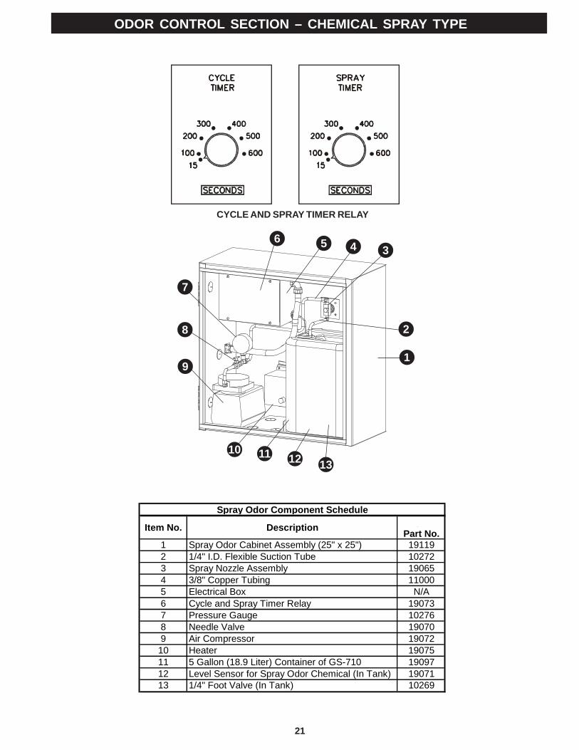
The Spray Odor Control includes two (2) timers, one (1) forthe “Cycle Timer” (this is the spray ”OFF” timer) and one (1)for the “Spray Timer” (this is the spray “ON” timer). Bothtimers are calibrated and can be set between 5 and 600seconds. The factory/setting is always 15 seconds “ON” and15 seconds “OFF”.
CYCLE TIMERTo set the “Off” period, turn the dial to the desired off timeinterval.
SPRAY TIMERTo set the “On” period, turn the dial to the desired on timeinterval.
AIR PRESSUREFactory set to 20 PSIG
Electrical ControlsTo adjust the spray odor cycle and timers, open the SprayOdor Cabinet, and remove the screwed-in-place timer con-trol cover plate. Adjust as necessary for satisfactory odorcontrol.
CAUTION: Always de-energize the C-TPF before open-ing the Electrical and Timer Control Panel inside theOdor Spray Cabinet.
SPRAY ODOR CONTROL SPRAY NOZZLE ASSEMBLY
NOZZLE MAINTENANCETo obtain the best performance from your nozzle, it maybecome necessary to clean it periodically.
The nozzle may become clogged and cease spraying dueto factors such as dust, foreign particles accumulated in theorifice, and/or leakage in the air or liquid section of the nozzle.
The following procedure should be done to maintain thenozzle’s performance:
1. Check the air line, which is connected from the com-pressor unit to the compression fitting and threaded intothe air inlet side of the nozzle, for any leakage.
2. Check the liquid suction line, which is connected to theliquid inlet side of the nozzle, and ensure that it is im-mersed in the odor control solution.
3. If it appears that the nozzle is only blowing air and doesnot lift up the odor control solution out of the container,do the following:
Remove the cleanout plug from the nozzle body and, usinga very thin pin or wire, clean the hole in the fluid cap (orifice)and replace the cleanout plug. Remove the foot valve fromthe liquid container and inspect screen for clogging. Brushclean if clogged.
ODOR CONTROL SECTION – CHEMICAL SPRAY TYPE
SPRAY ODOR CHEMICALIn order for the spray odor system to work correctly the sys-tem must be supplied with a chemical solution. This solu-tion in conjunction with the delivery nozzle system that finelyatomizes the spray is what makes the system work. Werecommend the use of FORMULA GS-710. This materialhas been effective at removing between 80% and 90% ofthe odors from the kitchen exhaust in many applications.For the contact information of the nearest distributor of FOR-MULA GS-710:
Captive-Aire Systems, Inc.360 Northbrook DriveYoungsville, NC 27596Phone: (866) 784-6900Fax: (919) 554-9374Website www.captiveaire.com
21
ODOR CONTROL SECTION – CHEMICAL SPRAY TYPE
CYCLE AND SPRAY TIMER RELAY
1
2
3456
7
8
9
10 11 12 13
Item No. Description GaylordPart No.
1 Spray Odor Cabinet Assembly (25" x 25") 191192 1/4" I.D. Flexible Suction Tube 102723 Spray Nozzle Assembly 190654 3/8" Copper Tubing 110005 Electrical Box N/A6 Cycle and Spray Timer Relay 190737 Pressure Gauge 102768 Needle Valve 190709 Air Compressor 1907210 Heater 1907511 5 Gallon (18.9 Liter) Container of GS-710 1909712 Level Sensor for Spray Odor Chemical (In Tank) 1907113 1/4" Foot Valve (In Tank) 10269
Spray Odor Component Schedule
22
EXHAUST FAN SECTION
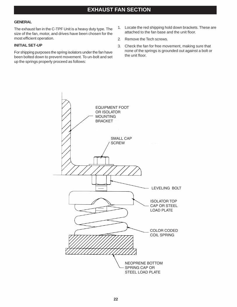
GENERAL
The exhaust fan in the C-TPF Unit is a heavy duty type. Thesize of the fan, motor, and drives have been chosen for themost efficient operation.
INITIAL SET-UP
For shipping purposes the spring isolators under the fan havebeen bolted down to prevent movement. To un-bolt and setup the springs properly proceed as follows:
EQUIPMENT FOOT OR ISOLATOR MOUNTING BRACKET
SMALL CAP SCREW
LEVELING BOLT
ISOLATOR TOP CAP OR STEEL LOAD PLATE
COLOR CODED COIL SPRING
NEOPRENE BOTTOM SPRING CAP OR STEEL LOAD PLATE
1. Locate the red shipping hold down brackets. These areattached to the fan base and the unit floor.
2. Remove the Tech screws.
3. Check the fan for free movement, making sure thatnone of the springs is grounded out against a bolt orthe unit floor.
23
EXHAUST FAN SECTION (Continued)
IPRE-OPERATIONAL MAINTENANCE
Before starting the exhaust fan perform the following pre-operational maintenance:
1. Set screws & Belts:a. Rotate fan impeller to check for shifting that may
have occured during shipment. If necessary, shiftwheel position and re-tighten.
b. Check belt and pulley alignment.c. Check tightness of setscrews in blower wheel hub.d. Check tightness of set screws in bearing locking
collar.e. Check tightness of set screws in motor and fan
pulleys.f. Check tightness of all frame bolts and base bolts.g. Check tightness of bearing mounting bolts.
2. Belt tension. Take up or relieve tension in belts so thatthere is approximately ¾” to 1" deflection under 3 poundspressure based on 2½ to 3 foot centers on drive. Adjust-ment of belt tension is accomplished by use of adjustablemotor base.
INITIAL FAN LUBRICATION
To prevent corrosion bearings should receive grease and berotated. Turn the wheel by hand while greasing bearings. Aclean 1/16" bead of grease must appear on each side ofeach bearing. Refer to specific bearing lubricating instruc-tions on the fan.
Bearings which are to be stored or idle for an extended pe-riod of time should be wrapped in a neutral grease-proofpaper, foil, or plastic film.
After long-term storage, grease should be purged from thebearings and fresh grease injected prior to start-up.
INITIAL OPERATION
After pre-operational checks, unit is ready for operation:1. Start up blower. Check rotation.2. If blower impeller is turning in the wrong direction, re-
verse rotation per instructions furnished by motor manu-facturer.
FAN PREVENTIVE MAINTENANCE
Every six months conduct the following maintenance:
1. Check for condition and tension of belts. Replacecracked, glazed or frayed belts. Re-check tension after48 hours and re-tension if necessary. Do not over-tightenbelts or bearing damage may result. Belt should de-press its width when pressed firmly inward at midwaypoint between the pulleys and belt should be tight enoughto prevent slippage. When replacing worn belt, replacemotor pulley if “shoulder” has a worn-in groove.
2. Check fan and motor bearings for possible binding, noiseor overheating. Lubricate fan in accordance with instruc-tions on fan housing.
4. Motors generally used are of the sleeve bearing typeand require periodic oiling. A good grade of ASE No. 10lubricating oil should be inserted into the oiler connec-tions on each end of the motor about every two months.Not more than a teaspoonful should be used; over-oilingwill result in oil drip.
TROUBLESHOOTING
1. Reduced Airflow:a. Blower impellers operating in wrong direction.b. Belt slippage or belts broken.c. Overload, starter cutout.
2. Noise in Blower:a. Bad bearings.b. Loose tie rods or blades.c. Blower wheels loose on shaft, wheels rubbing on
housing.d. Drive pulley loose on shaft.e. Foreign object located in blower wheel or blower
housing.
Necessary Action - Correct situation found immediately,as continued operation can shorten life of component partsand result in poor airflow and eventual general shut-down ofsystem until needed repair is made.
24
NAMEPLATE DATA
C-TPF NAMEPLATE
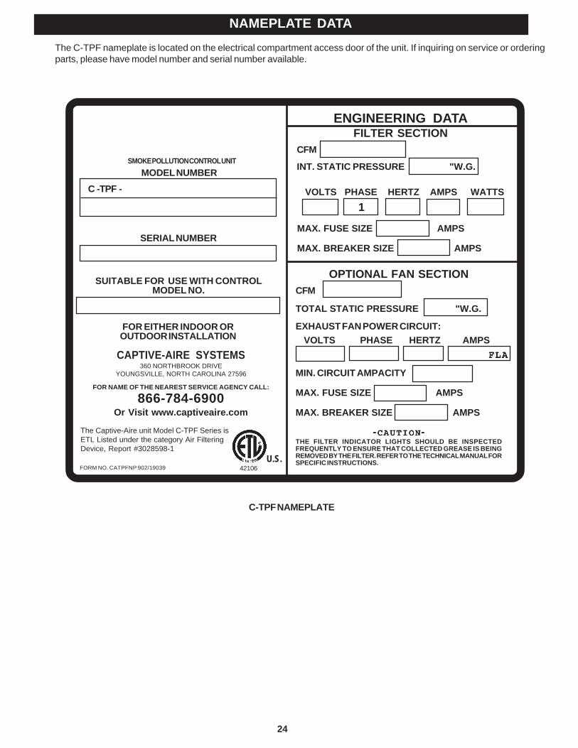
The C-TPF nameplate is located on the electrical compartment access door of the unit. If inquiring on service or orderingparts, please have model number and serial number available.
360 NORTHBROOK DRIVEYOUNGSVILLE, NORTH CAROLINA 27596
TOTAL STATIC PRESSURE "W.G.
EXHAUST FAN POWER CIRCUIT:
OPTIONAL FAN SECTIONCFM
ENGINEERING DATAFILTER SECTION
CFM
INT. STATIC PRESSURE "W.G.
FOR EITHER INDOOR OROUTDOOR INSTALLATION
VOLTS PHASE HERTZ AMPS WATTS
SERIAL NUMBER
MODEL NUMBER
SUITABLE FOR USE WITH CONTROLMODEL NO.
SMOKE POLLUTION CONTROL UNIT
VOLTS PHASE HERTZ AMPS
MIN. CIRCUIT AMPACITY
MAX. FUSE SIZE AMPS
MAX. BREAKER SIZE AMPS
-----CAUTIONCAUTIONCAUTIONCAUTIONCAUTION-----THE FILTER INDICATOR LIGHTS SHOULD BE INSPECTEDFREQUENTLY TO ENSURE THAT COLLECTED GREASE IS BEINGREMOVED BY THE FILTER. REFER TO THE TECHNICAL MANUAL FORSPECIFIC INSTRUCTIONS.
CAPTIVE-AIRE SYSTEMS
FOR NAME OF THE NEAREST SERVICE AGENCY CALL:
866-784-6900Or Visit www.captiveaire.com
FORM NO. CATPFNP 902/19039
MAX. FUSE SIZE AMPS
MAX. BREAKER SIZE AMPS
1
FLAFLAFLAFLAFLA
C -TPF -
U.S.
The Captive-Aire unit Model C-TPF Series isETL Listed under the category Air FilteringDevice, Report #3028598-1
42106
25
C-TPF SERIES OPERATING MATRIX
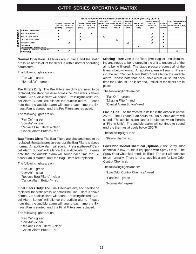
Normal Operation: All filters are in place and the staticpressure across all of the filters is within normal operatingparameters.
The following lights are on:
“Fan On” – green“Normal Air” – green
Pre Filters Dirty: The Pre Filters are dirty and need to bereplaced, the static pressure across the Pre Filters is abovenormal. An audible alarm will sound. Pressing the red “Can-cel Alarm Button” will silence the audible alarm. Pleasenote that the audible alarm will sound each time the Ex-haust Fan is started, until the Pre Filters are replaced.
The following lights are on:
“Fan On” – green“Low Air” – clear“Replace Pre Filters” – clear“Cancel Alarm Button”– red
Bag Filters Dirty: The Bag Filters are dirty and need to bereplaced, the static pressure across the Bag Filters is abovenormal. An audible alarm will sound. Pressing the red “Can-cel Alarm Button” will silence the audible alarm. Pleasenote that the audible alarm will sound each time the Ex-haust Fan is started, until the Bag Filters are replaced.
The following lights are on:
“Fan On” – green“Low Air” – clear“Replace Bag Filters” – clear“Cancel Alarm Button”– red
Final Filters Dirty: The Final Filters are dirty and need to bereplaced, the static pressure across the Final Filters is abovenormal. An audible alarm will sound. Pressing the red “Can-cel Alarm Button” will silence the audible alarm. Pleasenote that the audible alarm will sound each time the Ex-haust Fan is started, until the Final Filters are replaced.
The following lights are on:
“Fan On” – green“Low Air” – clear“Replace Final Filters” – clear“Cancel Alarm Button”– red
Missing Filter: One of the filters (Pre, Bag, or Final) is miss-ing and needs to be returned in the unit to ensure all of theair is being filtered. The static pressure across all of thefilters is below normal. An audible alarm will sound. Press-ing the red “Cancel Alarm Button” will silence the audiblealarm. Please note that the audible alarm will sound eachtime the Exhaust Fan is started, until all of the filters are inplace.
The following lights are on:
“Fan On” – green“Missing Filter” – red“Cancel Alarm Button”– red
Fire in Unit: The thermostat installed in the airflow is above250°F. The Exhaust Fan shuts off. An audible alarm willsound. The audible alarm cannot be silenced when there isa “Fire in Unit”. The audible alarm will continue to sounduntil the thermostat cools below 250°F.
The following light is on:
"Fire In Unit” – red
Low Odor Control Chemical (Optional): The Spray Odorchemical is low, if unit is equipped with Spray Odor. TheSpray Odor Chemical needs be filled. The unit will continueto run normally. There is not an audible alarm for Low OdorControl Chemical.
The following lights are on:
“Low Odor Control Chemical” – red
"Fan On" – green
"Normal Air" – green
"FAN ON"LIGHT ON(GREEN)
"NORMAL AIR"LIGHT ON(GREEN)
"LOW AIR"LIGHT ON
(RED)
"REPLACE PRE FILTERS"
LIGHT ON (CLEAR)
"REPLACEBAG FILTERS"
LIGHT ON (CLEAR)
"REPLACEFINAL FILTERS"
LIGHT ON (CLEAR)
"MISSING FILTER"
LIGHT ON (RED)
"FIRE IN UNIT"LIGHT ON
(RED)
"CANCEL ALARM BUTTON"LIGHT ON
(RED)
AUDIBLE ALARM
SOUNDS
"LOW ODOR CONTROL CHEMICAL
LIGHT ON (OPTIONAL) (RED)
X XX X X X XX X X X XX X X X X
X X X XX X
X X X
EXPLANATION OF FILTER MONITORING STATION (FM-100) LIGHTS
NORMAL OPERATION
PRE FILTERS DIRTY
BAG FILTERS DIRTY
FINAL FILTERS DIRTY
MISSING FILTERFIRE IN UNIT(THERMOSTAT ABOVE 250°F)LOW ODOR CONTROL CHEMICAL (OPTIONAL)R
SPC
-TPF
MO
DES
26
C – TPF PRESSURE SWITCH TUBING DIAGRAM
27
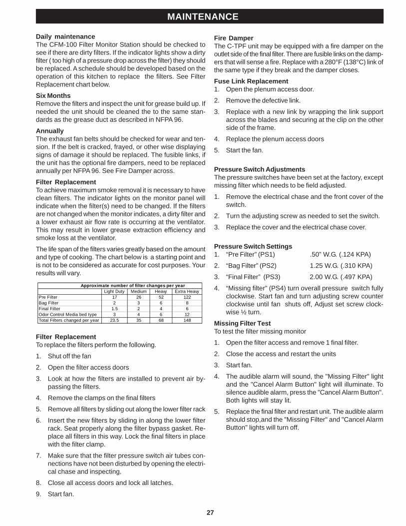
Daily maintenanceThe CFM-100 Filter Monitor Station should be checked tosee if there are dirty filters. If the indicator lights show a dirtyfilter ( too high of a pressure drop across the filter) they shouldbe replaced. A schedule should be developed based on theoperation of this kitchen to replace the filters. See FilterReplacement chart below.
Six MonthsRemove the filters and inspect the unit for grease build up. Ifneeded the unit should be cleaned the to the same stan-dards as the grease duct as described in NFPA 96.
AnnuallyThe exhaust fan belts should be checked for wear and ten-sion. If the belt is cracked, frayed, or other wise displayingsigns of damage it should be replaced. The fusible links, ifthe unit has the optional fire dampers, need to be replacedannually per NFPA 96. See Fire Damper across.
Filter ReplacementTo achieve maximum smoke removal it is necessary to haveclean filters. The indicator lights on the monitor panel willindicate when the filter(s) need to be changed. If the filtersare not changed when the monitor indicates, a dirty filter anda lower exhaust air flow rate is occurring at the ventilator.This may result in lower grease extraction efficiency andsmoke loss at the ventilator.
The life span of the filters varies greatly based on the amountand type of cooking. The chart below is a starting point andis not to be considered as accurate for cost purposes. Yourresults will vary.
Filter ReplacementTo replace the filters perform the following.
1. Shut off the fan
2. Open the filter access doors
3. Look at how the filters are installed to prevent air by-passing the filters.
4. Remove the clamps on the final filters
5. Remove all filters by sliding out along the lower filter rack
6. Insert the new filters by sliding in along the lower filterrack. Seat properly along the filter bypass gasket. Re-place all filters in this way. Lock the final filters in placewith the filter clamp.
7. Make sure that the filter pressure switch air tubes con-nections have not been disturbed by opening the electri-cal chase and inspecting.
8. Close all access doors and lock all latches.
9. Start fan.
MAINTENANCE
Fire DamperThe C-TPF unit may be equipped with a fire damper on theoutlet side of the final filter. There are fusible links on the damp-ers that will sense a fire. Replace with a 280°F (138°C) link ofthe same type if they break and the damper closes.
Fuse Link Replacement1. Open the plenum access door.
2. Remove the defective link.
3. Replace with a new link by wrapping the link supportacross the blades and securing at the clip on the otherside of the frame.
4. Replace the plenum access doors
5. Start the fan.
Pressure Switch AdjustmentsThe pressure switches have been set at the factory, exceptmissing filter which needs to be field adjusted.
1. Remove the electrical chase and the front cover of theswitch.
2. Turn the adjusting screw as needed to set the switch.
3. Replace the cover and the electrical chase cover.
Pressure Switch Settings1. “Pre Filter” (PS1) .50” W.G. (.124 KPA)
2. “Bag Filter” (PS2) 1.25 W.G. (.310 KPA)
3. “Final Filter” (PS3) 2.00 W.G. (.497 KPA)
4. “Missing filter” (PS4) turn overall pressure switch fullyclockwise. Start fan and turn adjusting screw counterclockwise until fan shuts off, Adjust set screw clock-wise ½ turn.
Missing Filter TestTo test the filter missing monitor
1. Open the filter access and remove 1 final filter.
2. Close the access and restart the units
3. Start fan.
4. The audible alarm will sound, the "Missing Filter" lightand the "Cancel Alarm Button" light will illuminate. Tosilence audible alarm, press the "Cancel Alarm Button".Both lights will stay lit.
5. Replace the final filter and restart unit. The audible alarmshould stop,and the "Missing Filter" and "Cancel AlarmButton" lights will turn off.
Approximate number of filter changes per yearLight Duty Medium Heavy Extra Heavy
Pre Filter 17 26 52 122Bag Filter 2 3 6 8Final Filter 1.5 2 4 6Odor Control Media bed type 3 4 6 12Total Filters changed per year 23.5 35 68 148
28
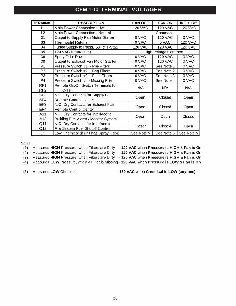
CFM-100 TERMINAL VOLTAGES
TERMINAL DESCRIPTION FAN OFF FAN ON INT. FIREL1 Main Power Connection : Hot 120 VAC 120 VAC 120 VACL2 Main Power Connection : Neutral31 Output to Supply Fan Motor Starter 0 VAC 120 VAC 0 VAC33 Thermostat Return 0 VAC 0 VAC 120 VAC34 Fused Supply to Press. Sw. & T-Stat. 120 VAC 120 VAC 120 VAC35 120 VAC Neutral Leg36 Spray Odor Power 0 VAC 120 VAC 0 VAC38 Output to Exhaust Fan Motor Starter 0 VAC 120 VAC 0 VACP1 Pressure Switch #1 - Pre-Filters 0 VAC See Note 1 0 VACP2 Pressure Switch #2 - Bag Filters 0 VAC See Note 2 0 VACP3 Pressure Switch #3 - Final Filters 0 VAC See Note 3 0 VACP4 Pressure Switch #4 - Missing Filter 0 VAC See Note 4 0 VAC
RF1RF2
Remote On/Off Switch Terminals for RSPC-TPF N/A N/A N/A
SF3SF4
N.O. Dry Contacts for Supply FanRemote Control Center Open Closed Open
EF3EF4
N.O. Dry Contacts for Exhaust FanRemote Control Center Open Closed Open
A11A12
N.O. Dry Contacts for Interface toBuilding Fire Alarm / Monitor System Open Open Closed
Q11Q12
N.C. Dry Contacts for Interface toFire System Fuel Shutoff Control Closed Closed Open
LC Low Chemical (if unit has Spray Odor) See Note 5 See Note 5 See Note 5
Notes(1) Measures HIGH Pressure, when Filters are Dirty - 120 VAC when Pressure is HIGH & Fan is On(2) Measures HIGH Pressure, when Filters are Dirty - 120 VAC when Pressure is HIGH & Fan is On(3) Measures HIGH Pressure, when Filters are Dirty - 120 VAC when Pressure is HIGH & Fan is On(4) Measures LOW Pressure, when a Filter is Missing - 120 VAC when Pressure is LOW & Fan is On
(5) Measures LOW Chemical - 120 VAC when Chemical is LOW (anytime)
High Voltage Common
Common
29
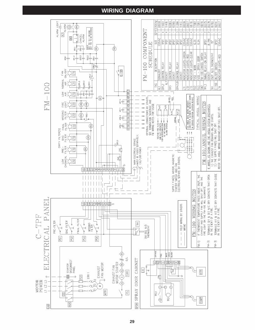
WIRING DIAGRAM
30
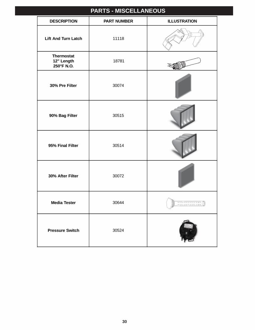
PARTS - MISCELLANEOUSDESCRIPTION PART NUMBER ILLUSTRATION
Lift And Turn Latch 11118
Thermostat12" Length250°F N.O.
18781
30% Pre Filter 30074
90% Bag Filter 30515
95% Final Filter 30514
30% After Filter 30072
Media Tester 30644
Pressure Switch 30524
31
Start up Procedure for RSCP-TPFCheck duct work for proper connection to unit. All incomingduct work should be minimum 18 GA SS or 16 GA BI andfully welded or joined per NFPA 96 requirements
Check the fan section and remove shipping braces if sup-plied per the instructions on pages 22 and 23
If the unit was shipped in sections. Check for proper assem-bly of the unit on pages 14 and 15. All field joints must bewelded grease and water tight.
Check for proper and complete installation of all filters. Ifsome are missing locate them and install per the instruc-tions on page 27.
If a media bed odor control system was provided make surethat it was installed per the instructions on pages 18 and19.
If a spray odor system was provided, locate the 5 gallon pailof GS-710 provided in the spray odor control cabinet. Re-move the lid and install the pick up tube and level sensor.For field adjustments refer to pages 20 and 21.
C - TPF STARTUP INSTRUCTIONS
Check for proper air flow at the kitchen hood. Make sure thatall access panels have been installed in the duct work andall filters or cartridges are in place in the hood. Check forproper air volume per hood manufacturers instructions. Mini-mum flow should be the design volume. However, flows of upto 15% high are acceptable. The air flow will drop as thefilters become dirty. Starting high will assure smoke captureeven with filter loading.
Air volumes of 30 to 50% of design or a strong vibration mayindicate that the fan is rotating backwards. Verify Fan rota-tion. If air flow still low or excessive vibration check fan forloose components, duct discharge may be blocked, or ac-cess panels open. Excessive vibration may be caused byshipping braces still in place.
Once the proper air flow is set. The missing filter switchneeds to be set per the instructions under “Pressure SwitchAdjustments” Item 4 on page 27. Perform the Filter Re-moval Test to verify operation.
Cap
tive-
Aire
C-T
PF S
tart
-Up
Insp
ectio
n R
epor
tTh
is s
tart-
up R
epor
t Use
d Fo
r C-T
PF
Pol
lutio
n C
ontro
l Uni
tsO
ne R
epor
t Mus
t Be
Com
plet
ed F
or E
ach
Uni
t
File
Num
ber
____
____
____
____
____
____
____
____
____
____
____
____
_Jo
b N
ame
____
____
____
____
____
____
____
____
____
____
____
____
_A
ddre
ss__
____
____
____
____
____
____
____
____
____
____
____
___
____
____
____
____
____
____
____
____
____
____
____
____
_
NAM
EPLA
TE D
ATA:
Mod
el N
o__
____
____
____
____
____
____
____
____
____
____
____
___
Ser
ial N
o__
____
____
____
____
____
____
____
____
____
____
____
___
CFM
____
____
____
____
____
____
____
____
____
____
____
____
_
PREL
IMIN
ARY
CH
ECK
LIST
UN
IT E
QU
IPPE
D W
ITH
EXH
AUST
FAN
? Y
es
No
UN
IT E
QU
IPPE
D W
ITH
OD
OR
CO
NTR
OL?
Yes
N
o
ALL
UN
ITS:
1. O
pen
all r
emov
able
acc
ess
pane
ls in
clud
ing
elec
trica
ldi
scon
nect
pan
el.
2. C
ompl
ete
a th
orou
gh in
spec
tion
of th
e un
it fo
r any
ship
ping
, han
dlin
g or
inst
alla
tion
dam
ages
and
, if a
ny,
note
und
er c
omm
ents
.3.
Ver
ify a
ll P
re F
ilter
s ar
e in
pla
ce.
4. V
erify
all
Bag
File
rs a
re in
pla
ce.
5. V
erify
all
Fina
l Filt
ers
are
in p
lace
.6.
Ver
ify th
at th
e sp
are
fuse
s ar
e pr
ovid
ed in
side
the
CFM
-100
.
IF U
NIT
EQ
UIP
PED
WIT
H E
XHA
UST
FA
N:
7. V
erify
that
the
optio
nal w
all i
nsul
atio
n is
sec
ure
and
has
not l
oose
ned
in s
hipm
ent i
f a h
ouse
d fa
n.8.
Ver
ify th
at a
ll sh
ippi
ng ti
edow
ns, b
olts
and
bra
ces
have
bee
n re
mov
ed fr
om e
xhau
st fa
n sp
ring
isol
ator
s.9.
Ver
ify th
at th
e fa
n flo
ats
freel
y on
the
sprin
g is
olat
ors
and
the
fan
whe
el tu
rns
freel
y by
rot
atin
g th
e pu
lleys
.10
. V
erify
that
all
bear
ing
set c
olla
rs a
re ti
ght.
11.
Ver
ify t
he e
xhau
st d
isch
arge
is n
ot o
bstru
cted
or
dire
cted
tow
ard
any
stru
ctur
e.12
. V
erify
that
the
spar
e fa
n be
lts a
re p
rovi
ded
insi
de th
efa
n ho
usin
g.
IF U
NIT
IS E
QU
IPPE
D W
ITH
MED
IA B
ED O
DO
R C
ON
TRO
L:14
. V
erify
all
mod
ules
are
in p
lace
and
full
of o
dor c
ontro
lm
edia
.15
. T
ype
of o
dor c
ontro
l med
ia b
ed
car
bon
pot
assi
um p
erm
anag
anat
e16
.
Uni
t equ
ippe
d w
ith a
fire
pro
tect
ion
syst
em?
yes
N
o
If s
o, w
hat t
ype?
S
prin
kler
Wet
Che
mic
al
OPE
RAT
ION
AL
CH
ECK
LIST
TPF
SEC
TIO
N1.
Clo
se a
nd la
tch
all a
cces
s do
ors
& p
anel
s.2.
Ve
rify
that
all
circ
uit b
reak
ers
are
on a
nd p
ower
is s
uppl
ied
to th
e C
-TP
F.3.
P
lace
the
door
dis
conn
ect s
witc
h in
the
“On”
posi
tion.
4. T
urn
the
“Sta
rt Fa
n” s
witc
h on
the
CFM
-100
cabi
net o
n to
ene
rgiz
e th
e ex
haus
t fan
:a.
Exh
aust
Fan
sta
rt?
Yes
N
ob.
"Fan
On"
ligh
t on?
Y
es
No
FAN
SEC
TIO
N2.
C
heck
air
flow
at k
itche
n ho
od a
nd v
erify
air
volu
me
is a
t des
ign
or a
s m
uch
as 1
5% h
igh.
If n
ot h
ave:
a. B
alan
cer a
djus
t she
aves
on
5 H
P an
d sm
alle
r
mot
ors
b. H
ave
bala
ncer
cha
nge
shea
ves
on 7
.5 H
P a
nd
larg
er m
otor
s
ELEC
TRIC
AL P
ANEL
AN
D F
M-1
00O
nce
the
air
flow
is c
orre
ct
the
mis
sing
filte
r sw
itch
need
s to
be
set
1.
Tu
rn th
e se
t scr
ew o
n th
e #4
pre
ssur
e sw
itch
until
the
mis
sing
filte
r lig
ht c
omes
on.
2.
Bac
k of
f ¼ tu
rn
SPR
AY O
DO
R (I
f equ
ippe
d w
ith)
1.
Loc
ate
cont
aine
r of G
S-7
102.
P
lace
GS
-710
con
tain
er in
the
spra
y od
or c
abin
et3.
R
emov
e ca
p an
d in
stal
l pic
kup
tube
and
leve
lsw
itch
in c
onta
iner
4.
Ver
ify th
at b
oth
timer
s ar
e se
t to
15 s
econ
dsTh
is m
ay n
eed
to b
e ad
just
ed to
max
imiz
e th
esp
ray
odor
effe
ctiv
enes
s de
crea
sing
the
del
ay o
rin
crea
sing
the
spra
ying
tim
e w
ill im
prov
e th
eef
fect
i ven
ess
of t
he s
pray
odo
r. In
crea
sing
the
dela
y or
dec
reas
ing
the
spra
y tim
e w
ill re
duce
the
effe
ctiv
enes
s of
the
spr
ay o
dor
syst
em.
Dat
e of
Insp
ectio
n:__
____
____
____
____
____
____
_
Insp
ectio
n W
itnes
sed
By:
Nam
e:__
____
____
____
____
____
____
____
____
___
Title
:__
____
____
____
____
____
____
____
____
____
Sig
natu
re:_
____
____
____
____
____
____
____
____
_
Insp
ectio
n P
erfo
rmed
By:
Nam
e:__
____
____
____
____
____
____
____
____
___
Com
pany
:___
____
____
____
____
____
____
____
___
Com
men
ts__
____
____
____
____
____
____
____
____
____
____
____
____
____
____
____
____
____
____
____
____
____
____
____
____
____
____
____
____
____
____
____
____
____
____
____
____
____
____
____
____
____
____
____
____
____
____
____
____
____
____
____
____
____
____
____
____
____
____
____
____
____
____
____
____
____
____
____
____
____
____
____
____
____
____
____
____
____
____
____
____
____
____
____
____
____
____
____
____
____
____
____
____
____
____
____
____
____
____
____
____
____
____
____
____
____
____
____
____
____
____
____
____
____
____
____
____
____
____
____
____
____
____
____
____
____
____
____
____
____
____
____
____
____
____
____
____
____
____
____
____
____
____
____
____
____
____
____
____
____
____
____
____
____
____
____
____
____
____
____
____
____
____
____
____
____
____
____
____
____
____
____
____
____
____
____
____
____
____
____
____
____
____
____
____
____
____
____
____
____
____
____
____
____
____
____
____
____
____
____
____
____
____
____
____
____
____
____
____
____
____
____
____
____
____
____
____
____
____
____
____
____
____
____
____
____
____
____
____
____
____
____
____
____
____
____
____
____
____
____
____
____
Dis
tribu
tion:
Cap
tive-
Aire
Sys
tem
s / C
usto
mer
/ S
ales
Rep
CA
PTIV
E-A
IRE
SYST
EMS,
INC
., 36
0 N
OR
THB
RO
OK
DR
IVE
You
ngsv
ille,
NC
275
96 •
1-86
6-78
4-69
00 •
FAX
: 919
-554
-241
4 • e
mai
l:w
ebho
me@
capt
ivea
ire.c
om
LIMITED WARRANTY
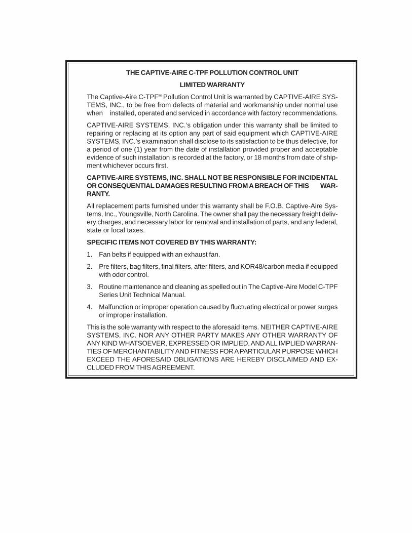
THE CAPTIVE-AIRE C-TPF POLLUTION CONTROL UNIT
LIMITED WARRANTY
The Captive-Aire C-TPFM Pollution Control Unit is warranted by CAPTIVE-AIRE SYS-TEMS, INC., to be free from defects of material and workmanship under normal usewhen installed, operated and serviced in accordance with factory recommendations.
CAPTIVE-AIRE SYSTEMS, INC.’s obligation under this warranty shall be limited torepairing or replacing at its option any part of said equipment which CAPTIVE-AIRESYSTEMS, INC.’s examination shall disclose to its satisfaction to be thus defective, fora period of one (1) year from the date of installation provided proper and acceptableevidence of such installation is recorded at the factory, or 18 months from date of ship-ment whichever occurs first.
CAPTIVE-AIRE SYSTEMS, INC. SHALL NOT BE RESPONSIBLE FOR INCIDENTALOR CONSEQUENTIAL DAMAGES RESULTING FROM A BREACH OF THIS WAR-RANTY.
All replacement parts furnished under this warranty shall be F.O.B. Captive-Aire Sys-tems, Inc., Youngsville, North Carolina. The owner shall pay the necessary freight deliv-ery charges, and necessary labor for removal and installation of parts, and any federal,state or local taxes.
SPECIFIC ITEMS NOT COVERED BY THIS WARRANTY:
1. Fan belts if equipped with an exhaust fan.
2. Pre filters, bag filters, final filters, after filters, and KOR48/carbon media if equippedwith odor control.
3. Routine maintenance and cleaning as spelled out in The Captive-Aire Model C-TPFSeries Unit Technical Manual.
4. Malfunction or improper operation caused by fluctuating electrical or power surgesor improper installation.
This is the sole warranty with respect to the aforesaid items. NEITHER CAPTIVE-AIRESYSTEMS, INC. NOR ANY OTHER PARTY MAKES ANY OTHER WARRANTY OFANY KIND WHATSOEVER, EXPRESSED OR IMPLIED, AND ALL IMPLIED WARRAN-TIES OF MERCHANTABILITY AND FITNESS FOR A PARTICULAR PURPOSE WHICHEXCEED THE AFORESAID OBLIGATIONS ARE HEREBY DISCLAIMED AND EX-CLUDED FROM THIS AGREEMENT.

FORM NO. TM CATPF 903/30679 © COPYRIGHT 2004, CAPTIVE-AIRE SYSTEMS, INC. LITHO USA
WORLDWIDE SALES, MANUFACTURING AND SERVICEFOR THE NAME AND LOCATION OF THE NEAREST
CERTIFIED SERVICE AGENCY, VISIT OUR WEB SITE:
WWW.CAPTIVEAIRE.COMOR CONTACT US AT:
CAPTIVE-AIRE SYSTEMS, INC.360 NORTHBROOK DRIVE
YOUNGSVILLE, NORTH CAROLINA 27596 U.S.APhone: 919-554-2414
1-866-784-6900Fax: 919-554-9374email: [email protected]
LOCAL SERVICE AGENCY