gb756 hydraulic installation tool (rivet...
TRANSCRIPT

GB756 INSTALLATION TOOL
GAGE BILT
MADE IN U.S.A.
GAGE BILT Inc. 44766 Centre Court (586) 226-1500
Clinton Twp. MI 48038 (586) 226-1505 Fax e-mail: [email protected] / www.gagebilt.com
GAGE BILT TOOLS ARE AVAILABLE WORLDWIDE E-MAIL US FOR A DISTRIBUTOR NEAR YOU.
S/N: 1226 AND ABOVE PLEASE CONTACT GAGE BILT FOR ALL OTHER SERIAL NUMBERS.
2 S/N: 1226 AND ABOVE PLEASE CONTACT GAGE BILT FOR ALL OTHER SERIAL NUMBERS.
REV. 3/14
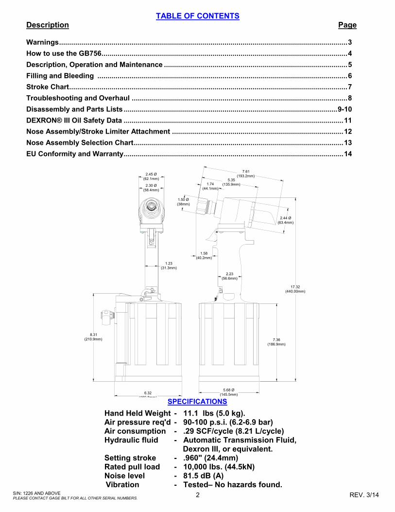
TABLE OF CONTENTS Description Page Warnings ............................................................................................................................................... 3
How to use the GB756 .......................................................................................................................... 4
Description, Operation and Maintenance ........................................................................................... 5
Filling and Bleeding ............................................................................................................................ 6
Stroke Chart .......................................................................................................................................... 7
Troubleshooting and Overhaul ........................................................................................................... 8
Disassembly and Parts Lists .......................................................................................................... 9-10
DEXRON® III Oil Safety Data ............................................................................................................. 11
Nose Assembly/Stroke Limiter Attachment ..................................................................................... 12
Nose Assembly Selection Chart ........................................................................................................ 13
EU Conformity and Warranty ............................................................................................................. 14
SPECIFICATIONS
Hand Held Weight - 11.1 lbs (5.0 kg). Air pressure req'd - 90-100 p.s.i. (6.2-6.9 bar) Air consumption - .29 SCF/cycle (8.21 L/cycle) Hydraulic fluid - Automatic Transmission Fluid,
Dexron III, or equivalent. Setting stroke - .960" (24.4mm) Rated pull load - 10,000 lbs. (44.5kN) Noise level - 81.5 dB (A)
Vibration - Tested– No hazards found.
17.32
(440.00mm)
7.36
(186.9mm)
5.68 Ø
(145.5mm)
2.23
(56.6mm)
1.50 Ø
(38mm)
7.61
(193.2mm)5.35
(135.9mm)1.74
(44.1mm)
2.44 Ø
(63.4mm)
1.58
(40.2mm)
1.23
(31.3mm)
2.45 Ø
(62.1mm)
2.30 Ø
(58.4mm)
8.31
(210.9mm)
6.32
(160.8mm)

3 S/N: 1226 AND ABOVE PLEASE CONTACT GAGE BILT FOR ALL OTHER SERIAL NUMBERS.
REV. 3/14
WARNING
Do not pull fastener unless it is placed in an assembly, pin will eject forcibly when pintail breaks
off. Severe personal injury may result.
WARNING
Do not operate without Stat-O-Seal (A-1155) and cap screws (402482). Pressurized hydraulic fluid may
cause severe personal injury.
WARNING
When operating, repairing or overhauling tool, wear approved eye protection. Do not look in front of
nose assembly or rear of tool when installing fastener.
WARNING
Always disconnect tool from power before performing any maintenance to any tool or nose assembly. Ensure that all connections are proper and there are no visible leaks from tool or hoses
before connecting to power.
WARNING
Do not operate if deflector, bottle, catcher bag or vacuum tube is removed or damaged, broken
pintails may eject forcibly from rear of tool. Severe personal injury may result.
CAUTION
Ensure that nose assembly and tip are properly matched for the fastener being installed.
CAUTION
Keep Nose Assemblies clean and free of chips and debris.
WARNING
Be sure there is adequate clearance for tool and operator's hands before proceeding. Keep fingers clear of any moving parts. Keep fingers clear from
fasteners and installed materials. Severe personal injury may result.
WARNING
It is required to use hearing protection. A test was carried out in a simulated work environment where
the background level was 73.2 dB(A). In this condition the max level was 81.5 dB(A). Therefore,
it is required where prolonged use, hearing protection be used.
CAUTION
Do not use beyond the design intent.
WARNING
Tool must be maintained in a safe working condition at all times and examined on a regular
daily basis for damage or wear. Any repair should be done by qualified personnel trained on Gage Bilt
procedures.
WARNING
Where prolonged use is foreseen, it is recommended a tool balancer be used. Check suspension device to ensure that it is secure.
WARNING
Do no use tool in explosive atmosphere.
CAUTION
Tool is not to be used as a hammer.
WARNING
Risk of crushing exists if nose assembly is not attached.
WARNING
It is recommended tool be operated 50 out of every 60 minutes, where prolonged use is expected.
WARNING Shock:
It is recommended operator wear a suitable glove during operation where prolonged use is expected.
WARNING Air pressure not to exceed 100 psi (6.9 bar).
SAFETY WARNINGS PLEASE READ THIS MANUAL BEFORE
SERVICING OR USING THIS TOOL.
WARNINGS:
MUST BE UNDERSTOOD TO AVOID SEVERE PERSONAL INJURY
CAUTIONS:
SHOW CONDITIONS THAT WILL DAMAGE EQUIPMENT OR STRUCTURE
4 S/N: 1226 AND ABOVE PLEASE CONTACT GAGE BILT FOR ALL OTHER SERIAL NUMBERS.
REV. 3/14
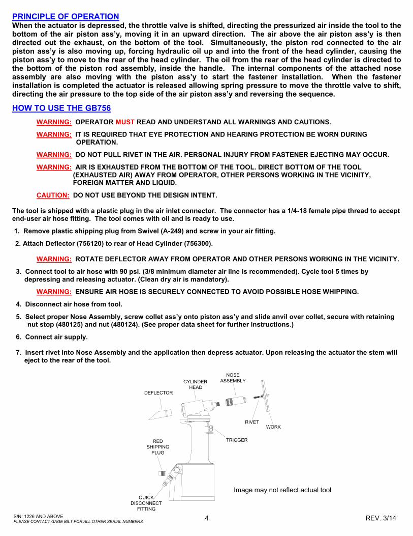
HOW TO USE THE GB756
WARNING: OPERATOR MUST READ AND UNDERSTAND ALL WARNINGS AND CAUTIONS.
WARNING: IT IS REQUIRED THAT EYE PROTECTION AND HEARING PROTECTION BE WORN DURING OPERATION.
WARNING: DO NOT PULL RIVET IN THE AIR. PERSONAL INJURY FROM FASTENER EJECTING MAY OCCUR.
WARNING: AIR IS EXHAUSTED FROM THE BOTTOM OF THE TOOL. DIRECT BOTTOM OF THE TOOL (EXHAUSTED AIR) AWAY FROM OPERATOR, OTHER PERSONS WORKING IN THE VICINITY, FOREIGN MATTER AND LIQUID.
CAUTION: DO NOT USE BEYOND THE DESIGN INTENT. The tool is shipped with a plastic plug in the air inlet connector. The connector has a 1/4-18 female pipe thread to accept end-user air hose fitting. The tool comes with oil and is ready to use.
1. Remove plastic shipping plug from Swivel (A-249) and screw in your air fitting.
2. Attach Deflector (756120) to rear of Head Cylinder (756300). WARNING: ROTATE DEFLECTOR AWAY FROM OPERATOR AND OTHER PERSONS WORKING IN THE VICINITY.
3. Connect tool to air hose with 90 psi. (3/8 minimum diameter air line is recommended). Cycle tool 5 times by depressing and releasing actuator. (Clean dry air is mandatory).
WARNING: ENSURE AIR HOSE IS SECURELY CONNECTED TO AVOID POSSIBLE HOSE WHIPPING.
4. Disconnect air hose from tool.
5. Select proper Nose Assembly, screw collet ass’y onto piston ass’y and slide anvil over collet, secure with retaining nut stop (480125) and nut (480124). (See proper data sheet for further instructions.)
6. Connect air supply.
7. Insert rivet into Nose Assembly and the application then depress actuator. Upon releasing the actuator the stem will eject to the rear of the tool.
DEFLECTOR
CYLINDER
HEAD
NOSE
ASSEMBLY
RIVETWORK
RED
SHIPPING
PLUG
QUICK
DISCONNECT
FITTING
TRIGGER
Image may not reflect actual tool
PRINCIPLE OF OPERATION When the actuator is depressed, the throttle valve is shifted, directing the pressurized air inside the tool to the bottom of the air piston ass’y, moving it in an upward direction. The air above the air piston ass’y is then directed out the exhaust, on the bottom of the tool. Simultaneously, the piston rod connected to the air piston ass’y is also moving up, forcing hydraulic oil up and into the front of the head cylinder, causing the piston ass’y to move to the rear of the head cylinder. The oil from the rear of the head cylinder is directed to the bottom of the piston rod assembly, inside the handle. The internal components of the attached nose assembly are also moving with the piston ass’y to start the fastener installation. When the fastener installation is completed the actuator is released allowing spring pressure to move the throttle valve to shift, directing the air pressure to the top side of the air piston ass’y and reversing the sequence.

5 S/N: 1226 AND ABOVE PLEASE CONTACT GAGE BILT FOR ALL OTHER SERIAL NUMBERS.
REV. 3/14
DESCRIPTION
WARNING: THE BALANCE OF THIS TOOL IS DESIGNED FOR VERTICAL USE AND IS NOT SUITED FOR ANY
OTHER APPLICATIONS. GAGE BILT WILL BE PLEASED TO ADVISE FOR YOUR SPECIFIC APPLI-CATION.
The GB756 is a hydraulic installation tool designed specifically for the efficient installation of a wide range of blind, lockbolt and Magna-Grip® fasteners thru 3/8" diameter. It weighs 11.1 lbs. (5.0kg) and can be operated in any position with one hand. It has a .960" (24.4mm) rivet setting stroke and a rated pull load of 10,000 lbs (44.5kN).
The GB756 riveter operates with 90 to 100 psi (6.2-6.9 bar) of air. At 90 psi. (6.2 bar) air pressure, the GB756 does not exceed 81.5 db (A) and consumes 6.0 cfm at 20 cycles per minute.
The air inlet is provided with 1/4-18 female pipe threads for accepting the user's air hose fitting.
Nose Assemblies that were designed for the model 353 installation tool mount directly on the GB756 without the use of an adapter.
Nose Assemblies that were designed for the model 352 installation tool will attach to the GB756 with the use of the 353352 nose assembly adapter.
NOSE ASSEMBLIES ARE NOT FURNISHED WITH THIS TOOL AND MUST BE ORDERED SEPARATELY (SEE PAGE 12).
MAINTENANCE
WARNING: EXCESSIVE CONTACT WITH HYDRAULIC FLUID AND LUBRICANTS SHOULD BE AVOIDED.
WARNING: MAINTENANCE PERSONNEL MUST READ AND UNDERSTAND ALL WARNINGS AND CAUTIONS.
WARNING: DISCONNECT TOOL FROM ITS AIR SOURCE BEFORE PERFORMING MAINTENANCE.
The performance of any tool depends upon good maintenance practices. Following these minimal require-ments for service and care will extend the life of your tool. *Only use an air supply set at 90-100 psi. (6.2-6.9 bar) equipped with a filter-regulator to prevent wear. *The tool will eventually lose some hydraulic oil. Keep the hydraulic system full and free of air by using the air bleeder (745163) on a regular basis. *Proper care by operator is necessary in maintaining full productivity and reducing down time. Read all applicable tool manuals and nose assembly data sheets prior to operating tools. *Keep nose assemblies, especially jaws, clean and free of chips and debris.
*All Screwed End Caps, Base Covers, Air Fittings, Actuators, Screws and Nose Assemblies are to be examined at the end of each working shift to check that they are secure.
*Check tool, all hoses and all couplings daily for damage or air/hydraulic leaks. Tighten or replace (if necessary). *For a complete overhaul, tool kit GB756TK is recommended.
TORQUE SPECIFICATIONS
Button Head Cap Screws (402479) = 35-40 inch lbs. Packing Plug (756218) = 45 foot lbs. Flexlock Nut (A-1089) = 17 foot lbs. End Cap (756116) = 50 foot lbs Button Head Cap Screws (402482)= 35-40 inch lbs. (Do NOT over-tighten)
Daily cleaning and lubrication of nose assembly will greatly reduce downtime and increase life of components. Using sewing machine oil, or an equivalent cleaner/lubricant, follow instructions below.
1. Disconnect tool vacuum line (if equipped). 2. Point nose assembly into oil as shown.
3.Cycle tool 8-10 times and wipe dry.
CLEANING AND LUBRICATING PROCEDURE
Image may not reflect actual tool
6 S/N: 1226 AND ABOVE PLEASE CONTACT GAGE BILT FOR ALL OTHER SERIAL NUMBERS.
REV. 3/14
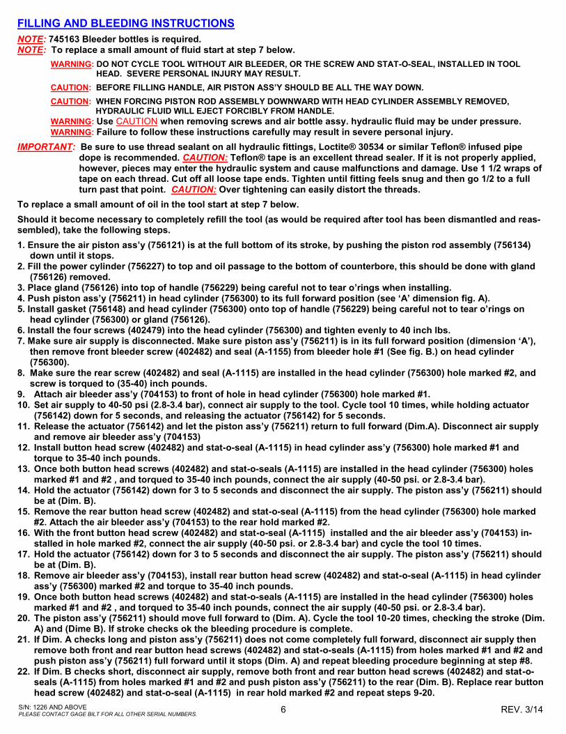
FILLING AND BLEEDING INSTRUCTIONS
NOTE: 745163 Bleeder bottles is required. NOTE: To replace a small amount of fluid start at step 7 below.
WARNING: DO NOT CYCLE TOOL WITHOUT AIR BLEEDER, OR THE SCREW AND STAT-O-SEAL, INSTALLED IN TOOL HEAD. SEVERE PERSONAL INJURY MAY RESULT.
CAUTION: BEFORE FILLING HANDLE, AIR PISTON ASS’Y SHOULD BE ALL THE WAY DOWN.
CAUTION: WHEN FORCING PISTON ROD ASSEMBLY DOWNWARD WITH HEAD CYLINDER ASSEMBLY REMOVED, HYDRAULIC FLUID WILL EJECT FORCIBLY FROM HANDLE.
WARNING: Use CAUTION when removing screws and air bottle assy. hydraulic fluid may be under pressure. WARNING: Failure to follow these instructions carefully may result in severe personal injury.
IMPORTANT: Be sure to use thread sealant on all hydraulic fittings, Loctite® 30534 or similar Teflon® infused pipe dope is recommended. CAUTION: Teflon® tape is an excellent thread sealer. If it is not properly applied, however, pieces may enter the hydraulic system and cause malfunctions and damage. Use 1 1/2 wraps of tape on each thread. Cut off all loose tape ends. Tighten until fitting feels snug and then go 1/2 to a full turn past that point. CAUTION: Over tightening can easily distort the threads.
To replace a small amount of oil in the tool start at step 7 below.
Should it become necessary to completely refill the tool (as would be required after tool has been dismantled and reas-sembled), take the following steps.
1. Ensure the air piston ass’y (756121) is at the full bottom of its stroke, by pushing the piston rod assembly (756134) down until it stops. 2. Fill the power cylinder (756227) to top and oil passage to the bottom of counterbore, this should be done with gland (756126) removed. 3. Place gland (756126) into top of handle (756229) being careful not to tear o’rings when installing. 4. Push piston ass’y (756211) in head cylinder (756300) to its full forward position (see ‘A’ dimension fig. A). 5. Install gasket (756148) and head cylinder (756300) onto top of handle (756229) being careful not to tear o’rings on head cylinder (756300) or gland (756126). 6. Install the four screws (402479) into the head cylinder (756300) and tighten evenly to 40 inch lbs. 7. Make sure air supply is disconnected. Make sure piston ass’y (756211) is in its full forward position (dimension ‘A’), then remove front bleeder screw (402482) and seal (A-1155) from bleeder hole #1 (See fig. B.) on head cylinder (756300). 8. Make sure the rear screw (402482) and seal (A-1115) are installed in the head cylinder (756300) hole marked #2, and
screw is torqued to (35-40) inch pounds. 9. Attach air bleeder ass’y (704153) to front of hole in head cylinder (756300) hole marked #1. 10. Set air supply to 40-50 psi (2.8-3.4 bar), connect air supply to the tool. Cycle tool 10 times, while holding actuator
(756142) down for 5 seconds, and releasing the actuator (756142) for 5 seconds. 11. Release the actuator (756142) and let the piston ass’y (756211) return to full forward (Dim.A). Disconnect air supply
and remove air bleeder ass’y (704153) 12. Install button head screw (402482) and stat-o-seal (A-1115) in head cylinder ass’y (756300) hole marked #1 and
torque to 35-40 inch pounds. 13. Once both button head screws (402482) and stat-o-seals (A-1115) are installed in the head cylinder (756300) holes
marked #1 and #2 , and torqued to 35-40 inch pounds, connect the air supply (40-50 psi. or 2.8-3.4 bar). 14. Hold the actuator (756142) down for 3 to 5 seconds and disconnect the air supply. The piston ass’y (756211) should
be at (Dim. B). 15. Remove the rear button head screw (402482) and stat-o-seal (A-1115) from the head cylinder (756300) hole marked
#2. Attach the air bleeder ass’y (704153) to the rear hold marked #2. 16. With the front button head screw (402482) and stat-o-seal (A-1115) installed and the air bleeder ass’y (704153) in-
stalled in hole marked #2, connect the air supply (40-50 psi. or 2.8-3.4 bar) and cycle the tool 10 times. 17. Hold the actuator (756142) down for 3 to 5 seconds and disconnect the air supply. The piston ass’y (756211) should
be at (Dim. B). 18. Remove air bleeder ass’y (704153), install rear button head screw (402482) and stat-o-seal (A-1115) in head cylinder
ass’y (756300) marked #2 and torque to 35-40 inch pounds. 19. Once both button head screws (402482) and stat-o-seals (A-1115) are installed in the head cylinder (756300) holes
marked #1 and #2 , and torqued to 35-40 inch pounds, connect the air supply (40-50 psi. or 2.8-3.4 bar). 20. The piston ass’y (756211) should move full forward to (Dim. A). Cycle the tool 10-20 times, checking the stroke (Dim.
A) and (Dime B). If stroke checks ok the bleeding procedure is complete. 21. If Dim. A checks long and piston ass’y (756211) does not come completely full forward, disconnect air supply then
remove both front and rear button head screws (402482) and stat-o-seals (A-1115) from holes marked #1 and #2 and push piston ass’y (756211) full forward until it stops (Dim. A) and repeat bleeding procedure beginning at step #8.
22. If Dim. B checks short, disconnect air supply, remove both front and rear button head screws (402482) and stat-o-seals (A-1115) from holes marked #1 and #2 and push piston ass’y (756211) to the rear (Dim. B). Replace rear button head screw (402482) and stat-o-seal (A-1115) in rear hold marked #2 and repeat steps 9-20.

7 S/N: 1226 AND ABOVE PLEASE CONTACT GAGE BILT FOR ALL OTHER SERIAL NUMBERS.
REV. 3/14
TOOL STROKE LIMITERSTROKE LIMITER
THICKNESSSTROKE "A" "B"
.96" .147" 1.107"
24.38mm 3.73mm 28.12mm
.68" .147" .827"
17.27mm 3.73mm 21.01mm
.75" .147" .897"
19.05mm 3.73mm 22.78mm
.375" .147" .522"
9.53mm 3.73mm 13.26mm
756153 .210
GB756
NONE
756155 .585
756152 .280
-
Figure “A”
STROKE CHART
Bleeder screw 402482 and seal A-1155 Bleeder screw 402482
and seal A-1155
Figure “B”
8 S/N: 1226 AND ABOVE PLEASE CONTACT GAGE BILT FOR ALL OTHER SERIAL NUMBERS.
REV. 3/14
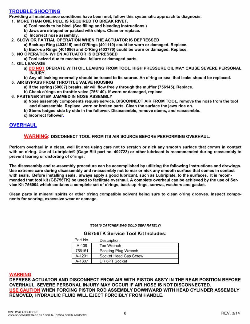
TROUBLE SHOOTING Providing all maintenance conditions have been met, follow this systematic approach to diagnosis. 1. MORE THAN ONE PULL IS REQUIRED TO BREAK RIVET. a) Tool needs to be bled. (See filling and bleeding instructions.) b) Jaws are stripped or packed with chips. Clean or replace. c) Incorrect nose assembly. 2. SLOW OR PARTIAL OPERATION WHEN THE ACTUATOR IS DEPRESSED a) Back-up Ring (403815) and O’Rings (401119) could be worn or damaged. Replace. b) Back-up Rings (401086) and O’Ring (403770) could be worn or damaged. Replace. 3. NO OPERATION WHEN ACTUATOR IS DEPRESSED a) Tool seized due to mechanical failure or damaged parts. 4. OIL LEAKAGE a) DO NOT OPERATE WITH OIL LEAKING FROM TOOL. HIGH PRESSURE OIL MAY CAUSE SEVERE PERSONAL INJURY. b) Any oil leaking externally should be traced to its source. An o'ring or seal that leaks should be replaced. 5. AIR BYPASS FROM THROTTLE VALVE HOUSING a) If the spring (50607) breaks, air will flow freely through the muffler (756145). Replace. b) Check o'rings on throttle valve (756140). If worn or damaged, replace. 6. FASTENER STEM JAMMED IN NOSE ASSEMBLY a) Nose assembly components require service. DISCONNECT AIR FROM TOOL, remove the nose from the tool and disassemble. Replace worn or broken parts. Clean the surface the jaws ride on. b) Stems lodged side by side in the follower. Disassemble, remove stems, and reassemble. c) Incorrect follower.
OVERHAUL
WARNING: DISCONNECT TOOL FROM ITS AIR SOURCE BEFORE PERFORMING OVERHAUL.
Perform overhaul in a clean, well lit area using care not to scratch or nick any smooth surface that comes in contact with an o'ring. Use of Lubriplate® (Gage Bilt part no. 402723) or other lubricant is recommended during reassembly to prevent tearing or distorting of o'rings. The disassembly and re-assembly procedure can be accomplished by utilizing the following instructions and drawings. Use extreme care during disassembly and re-assembly not to mar or nick any smooth surface that comes in contact with seals. Before installing seals, always apply a good lubricant, such as Lubriplate, to the surfaces. It is recom-mended that tool kit (GB756TK) be used to facilitate overhaul. A complete overhaul can be achieved by the use of Ser-vice Kit 756004 which contains a complete set of o'rings, back-up rings, screws, washers and gasket. Clean parts in mineral spirits or other o'ring compatible solvent being sure to clean o'ring grooves. Inspect compo-nents for scoring, excessive wear or damage.
WARNING DEPRESS ACTUATOR AND DISCONNECT FROM AIR WITH PISTON ASS’Y IN THE REAR POSITION BEFORE OVERHAUL. SEVERE PERSONAL INJURY MAY OCCUR IF AIR HOSE IS NOT DISCONNECTED. USE CAUTION WHEN FORCING PISTON ROD ASSEMBLY DOWNWARD WITH HEAD CYLINDER ASSEMBLY REMOVED, HYDRAULIC FLUID WILL EJECT FORCIBLY FROM HANDLE.
Part No. Description
A-139 Tee Wrench
756151 Packing Plug Wrench
A-1201 Socket Head Cap Screw
A-1307 DR 6PT Socket
GB756TK Service Tool Kit Includes:
(756610 CATCHER BAG SOLD SEPARATELY)
9 S/N: 1226 AND ABOVE PLEASE CONTACT GAGE BILT FOR ALL OTHER SERIAL NUMBERS.
REV. 3/14
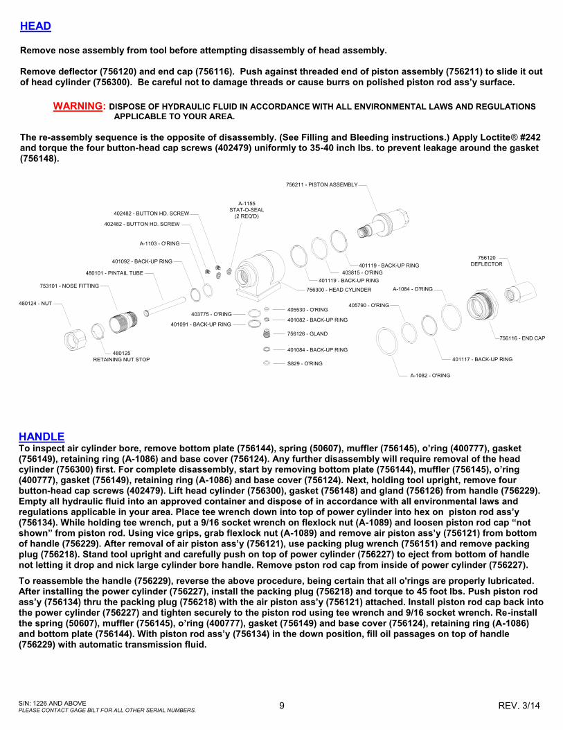
HEAD Remove nose assembly from tool before attempting disassembly of head assembly.
Remove deflector (756120) and end cap (756116). Push against threaded end of piston assembly (756211) to slide it out of head cylinder (756300). Be careful not to damage threads or cause burrs on polished piston rod ass’y surface.
WARNING: DISPOSE OF HYDRAULIC FLUID IN ACCORDANCE WITH ALL ENVIRONMENTAL LAWS AND REGULATIONS
APPLICABLE TO YOUR AREA. The re-assembly sequence is the opposite of disassembly. (See Filling and Bleeding instructions.) Apply Loctite® #242 and torque the four button-head cap screws (402479) uniformly to 35-40 inch lbs. to prevent leakage around the gasket (756148).
402482 - BUTTON HD. SCREW
A-1155
STAT-O-SEAL
(2 REQ'D)
401119 - BACK-UP RING
480125
RETAINING NUT STOPS829 - O'RING
401084 - BACK-UP RING
756126 - GLAND
401082 - BACK-UP RING
405530 - O'RING
403815 - O'RING
756211 - PISTON ASSEMBLY
A-1103 - O'RING
401092 - BACK-UP RING
480101 - PINTAIL TUBE
753101 - NOSE FITTING
480124 - NUT
403775 - O'RING
401091 - BACK-UP RING
405790 - O'RING
A-1084 - O'RING
756120
DEFLECTOR
A-1082 - O'RING
401117 - BACK-UP RING
756116 - END CAP
756300 - HEAD CYLINDER
401119 - BACK-UP RING
402482 - BUTTON HD. SCREW
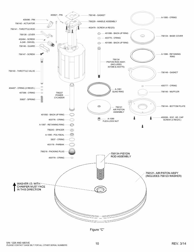
HANDLE To inspect air cylinder bore, remove bottom plate (756144), spring (50607), muffler (756145), o’ring (400777), gasket (756149), retaining ring (A-1086) and base cover (756124). Any further disassembly will require removal of the head cylinder (756300) first. For complete disassembly, start by removing bottom plate (756144), muffler (756145), o’ring (400777), gasket (756149), retaining ring (A-1086) and base cover (756124). Next, holding tool upright, remove four button-head cap screws (402479). Lift head cylinder (756300), gasket (756148) and gland (756126) from handle (756229). Empty all hydraulic fluid into an approved container and dispose of in accordance with all environmental laws and regulations applicable in your area. Place tee wrench down into top of power cylinder into hex on piston rod ass’y (756134). While holding tee wrench, put a 9/16 socket wrench on flexlock nut (A-1089) and loosen piston rod cap “not shown” from piston rod. Using vice grips, grab flexlock nut (A-1089) and remove air piston ass’y (756121) from bottom of handle (756229). After removal of air piston ass’y (756121), use packing plug wrench (756151) and remove packing plug (756218). Stand tool upright and carefully push on top of power cylinder (756227) to eject from bottom of handle not letting it drop and nick large cylinder bore handle. Remove pston rod cap from inside of power cylinder (756227).
To reassemble the handle (756229), reverse the above procedure, being certain that all o'rings are properly lubricated. After installing the power cylinder (756227), install the packing plug (756218) and torque to 45 foot lbs. Push piston rod ass’y (756134) thru the packing plug (756218) with the air piston ass’y (756121) attached. Install piston rod cap back into the power cylinder (756227) and tighten securely to the piston rod using tee wrench and 9/16 socket wrench. Re-install the spring (50607), muffler (756145), o’ring (400777), gasket (756149) and base cover (756124), retaining ring (A-1086) and bottom plate (756144). With piston rod ass’y (756134) in the down position, fill oil passages on top of handle (756229) with automatic transmission fluid.
10 S/N: 1226 AND ABOVE PLEASE CONTACT GAGE BILT FOR ALL OTHER SERIAL NUMBERS.
REV. 3/14
756148 - GASKET
407396 - O'RING
401086 - BACK-UP RING
50607 - SPRING
403776 - O'RING
401092 - BACK-UP RING
756227
POWER
CYLINDER
405496 - PIN
756142 - ACTUATOR
756141 - THROTTLE-ROD
756139 - LEVER
402464 - SCREW
A-249 - SWIVEL
756146 - GUARD
756147 - SCREW
756140 - THROTTLE VALVE
404407 - O'RING (2 REQ'D.)
A-1087 - RETAINING RING
756243 - SPACER
A-1095 - POLYSEAL
S837 - O'RING
403176 - PARBAK
756218 - PACKING PLUG
400779 - O'RING
401086 - BACK-UP RING
403770 - O'RING
756134
PISTON ROD ASSY.
(INCLUDES
401086 & 403770)
A-1081
QUAD RING
756121
AIR PISTON
ASSEMBLY
A-1089
FLEX-LOCK NUT
400056 - SOC. HD. CAP
SCREW (3 REQ'D.)
756144 - BOTTOM PLATE
756145 - MUFFLER
400777 - O'RING
756149 - GASKET
A-1086 - RETAINING
RING
756124 - BASE COVER
A-1085 - O'RING
400621 - PIN
756229 - HANDLE ASSEMBLY
402479 - SCREW (4 REQ'D)
Figure “C”

11 S/N: 1226 AND ABOVE PLEASE CONTACT GAGE BILT FOR ALL OTHER SERIAL NUMBERS.
REV. 3/14
FIRST AID
Skin: Wash thoroughly with soap and water as soon as possible. Casual contact requires no immediate attention. If irritation develops, consult a physician. Ingestion: Seek medical attention immediately. DO NOT INDUCE VOMITING. Eyes: Flush with copious amounts of water. If irritation develops, consult a physician. Inhalation: No significant adverse health effects are expected to occur on short term exposure. Remove from contaminated area. Apply artificial respiration if needed. If unconscious, consult a physician. FIRE
Suitable extinguishing media: CO2 dry powder, foam or water fog. DO NOT use water jets. ENVIRONMENT
Waste disposal: In accordance with all environmental laws and regulations applicable to your area. Spillage: Prevent entry into drains, sewers and water course. Soak up with diatomaceous earth or
other inert material. Store in appropriate container for disposal.
HANDLING
Eye protection required. Protective gloves recommended. Chemically resistant boots and apron recommended. Use in well ventilated area.
COMBUSTIBILITY
Slightly combustible when heated above flash point. Will release flammable vapor which can burn in open or be explosive in confined spaces if exposed to source of ignition.
PROPERTIES
Specific Gravity 0.863 Weight per gallon 7.18
Open flash point >200°C (392°F)
DEXRON® III OIL SAFETY DATA
12 S/N: 1226 AND ABOVE PLEASE CONTACT GAGE BILT FOR ALL OTHER SERIAL NUMBERS.
REV. 3/14
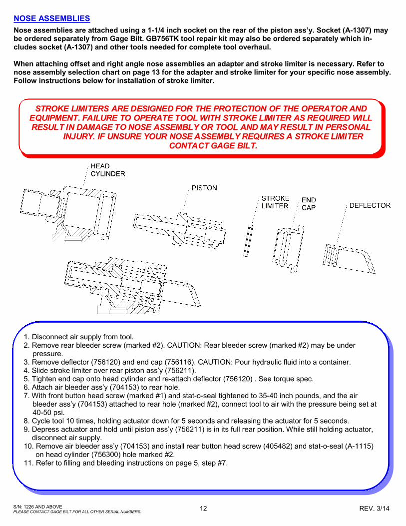
NOSE ASSEMBLIES
Nose assemblies are attached using a 1-1/4 inch socket on the rear of the piston ass’y. Socket (A-1307) may be ordered separately from Gage Bilt. GB756TK tool repair kit may also be ordered separately which in-cludes socket (A-1307) and other tools needed for complete tool overhaul. When attaching offset and right angle nose assemblies an adapter and stroke limiter is necessary. Refer to nose assembly selection chart on page 13 for the adapter and stroke limiter for your specific nose assembly. Follow instructions below for installation of stroke limiter.
STROKE LIMITERS ARE DESIGNED FOR THE PROTECTION OF THE OPERATOR ANDEQUIPMENT. FAILURE TO OPERATE TOOL WITH STROKE LIMITER AS REQUIRED WILLRESULT IN DAMAGE TO NOSE ASSEMBLY OR TOOL AND MAY RESULT IN PERSONAL
INJURY. IF UNSURE YOUR NOSE ASSEMBLY REQUIRES A STROKE LIMITERCONTACT GAGE BILT.
1. Disconnect air supply from tool. 2. Remove rear bleeder screw (marked #2). CAUTION: Rear bleeder screw (marked #2) may be under pressure. 3. Remove deflector (756120) and end cap (756116). CAUTION: Pour hydraulic fluid into a container. 4. Slide stroke limiter over rear piston ass’y (756211). 5. Tighten end cap onto head cylinder and re-attach deflector (756120) . See torque spec. 6. Attach air bleeder ass’y (704153) to rear hole. 7. With front button head screw (marked #1) and stat-o-seal tightened to 35-40 inch pounds, and the air bleeder ass’y (704153) attached to rear hole (marked #2), connect tool to air with the pressure being set at 40-50 psi. 8. Cycle tool 10 times, holding actuator down for 5 seconds and releasing the actuator for 5 seconds. 9. Depress actuator and hold until piston ass’y (756211) is in its full rear position. While still holding actuator, disconnect air supply. 10. Remove air bleeder ass’y (704153) and install rear button head screw (405482) and stat-o-seal (A-1115) on head cylinder (756300) hole marked #2. 11. Refer to filling and bleeding instructions on page 5, step #7.

13 S/N: 1226 AND ABOVE PLEASE CONTACT GAGE BILT FOR ALL OTHER SERIAL NUMBERS.
REV. 3/14
SELECTION CHART FOR GB756
GAGE BILT ALSO SUPPLIES PIN & COLLAR SWAGE INSPECTION GAGES TO CERTIFY CORRECT SWAGE INSTALLATION.
FASTENER DIA. **RIGHT ANGLE
13/64 ASP06-745B-23 ASP06-745C-48 ***ASP06-751B-54RA ASP06-204D-27OS ASP06-204D-37OS
17/64 ASP08-745B-23 ASP08-745C-48 ASP08-204D-27OS ASP08-204D-37OS
21/64 ASP10-755-23 ASP10-755-48 ASP10-204D-27OS ASP10-204D-37OS
1/4 BOM08-755-23
5/16 BOM10-756-26
3/16 NAS06-745B-12 NAS06-755-48 NAS06-204C-25OS NAS06-204C-30OS
NAS06-755-23 NAS06-204C-34OS
1/4 NAS08-745B-12 NAS08-755-48 NAS08-204C-25OS NAS08-204C-30OS
NAS08-755-23 NAS08-205A-31 NAS08-204C-34OS
5/16 LB10-745C-26 NAS10-756-48 NAS10-205A-31
3/8 LB12-756-26 NAS12-756-48 NAS12-205A-31
CONTAINER BOLT 3/8 HT12-745B-28
FLOOR BOLT 5/16 FT10-745B-26
5/32 LGP05-745B-12 LGP05-755-23 LGP05-204C-25OS LGP05-204C-30OS
LGP05-755-48 LGP05-204C-34OS
3/16 LGP06-745B-12 LGP06-755-23 LGP06-204C-25OS LGP06-204C-30OS
LGP06-755-48 LGP06-204C-34OS
1/4 LGP08-745B-12 LGP08-755-23 LGP08-204C-25OS LGP08-204C-30OS
LGP08-755-48 LGP08-204C-34OS LGP08-205A-31
5/16 LGP10-745B-12 LGP10-756-26 LGP10-205A-31
LGP10-756-48
3/8 LGP12-745B-12 LGP12-756-26 LGP12-205A-31
LGP12-756-48
5/32 NASS05-745B-12 NAST05-745B-12 NASS05-204C-25OS NAST05-204C-20OS
NASS05-755-23 NAST05-755-23 NASS05-204C-30OS NAST05-204C-30OS
NASS05-755-48 NAST05-755-48 NASS05-204C-34OS NAST05-204C-34OS
3/16 NAS06-745B-12 NAS06-755-23 NAS06-204C-25OS NAS06-204C-30OS
NAS06-755-48 NAS06-204C-34OS
1/4 NAS08-745B-12 NAS08-755B-23 NAS08-204C-25 NAS08-204C-30
NAS08-755-48 NAS08-204C-34 NAS08-205A-31
5/16 NAS10-745B-12 NAS10-756-26 NAS10-205C-31
NAS10-756-48
3/8 NAS12-745B-12 NAS12-756-26 NAS12-205A-31
NAS12-756-48
3/16 MG06-745-48
1/4 MG08-745-48
5/16 MG10-756-28
3/8 MG12-756-28
1/4 **MGL08-752A-21
5/16 MGL10-353-28
3/8 MGL12-353C-28
1/4 OS08-353A-48
5/16 OS10-756-26 OS10-756-48
3/8 OS12-756-26 OS12-756-48
5/32 SB05-745C-23 SB05-745C-48 ***SB05-751B-54RA SB05-204D-27OS SB05-204D-37OS
3/16 SB06-745B-23 SB06-745B-48 ***SB06-751B-54RA SB06-204D-27OS SB06-204D-37OS
1/4 SB08-755-23 SB08-755-48 ****SB08-713A-58RA SB08-204D-27OS SB08-204D-37OS
SB08-205-35
5/16 SB10-756-28 SB10-756-48 SB10-205A-35
3/8 SB12-756-28 SB12-756-48 SB12-205A-35
*ALL OFFSET 204 SERIES NOSES REQUIRE 353204 ADAPTER WITH 756152 STROKE LIMITER..
*ALL OFFSET 205 SERIES NOSES REQUIRE 353205 ADAPTER WITH 756153 STROKE LIMITER.
**NOSE REQUIRES 745751 ADAPTER
***-54RA RIGHT ANGLE SERIES NOSES REQUIRE 745751 ADAPTER WITH 756155 STROKE LIMITER.
****-58RA RIGHT ANGLE NOSES REQUIRE 745751 WITH 756152 STROKE LIMITER.
NOTE: THE LAST 2 DIGITS OF THE NOSE ASSEMBLY REPRESENTS THE LENGTH THE NOSE
EXTENDS FROM THE TOOL I.E. -20 = 2.0 INCHES 3/14
NAS and GP® SHEAR/TENSION
LOCKBOLTS
BACB30TY BACB30UA
BACB30TZ BACB30UB
BACB30DY BACB30GX
BACB30DX BACB30GP
BACB30GO BACB30GY
BACB30GW
STRAIGHT
LGP® LOCKBOLT
LGPL2SC-V BACB30VM
LGPL18SC-V BACB30XT
LGPL4SC-V ABS0548
LGPL2SP-V BACB30VN
LGPL4SP-V ASNA2392
LGPL8SC-V BACB30WD
LGPL9SC-V BACB30WB
LGPL9SP-V BACB30VY
*OFFSET
BOM®
AVBOLT®
ASP®
2 ASP & ASP PF
ASP FF & ASP F
ASP-LC and MAF
COMMERCIAL LOCKBOLTS
C6L®
AVDELOK®
GAGE BILT CERTIFIES THE GB756 WILL INSTALL THE ABOVE FASTENERS
BLIND BOLT (SINGLE ACTION)
WITH OR W/OUT DRIVE WASHER
MS90353S & U / MS90354S & U
MS21140S & U / MS21141S & U
CR7000 SERIES,
BACB30YY, YU, & YT
MULTI-GRIP LOCKBOLT
MAGNA-GRIP® and MAXLOK®
MULTI-GRIP STRUCTURAL
BLIND RIVET
OVERSIZE
STRUCTURAL
RIVET
ASP®, BOM ®, LGP®, C6L®, GP®, AND M AGNA-GRIP® ARE REGISTERED TRADEM ARKS OF ALCOA INC. AVBOLT®, AVDELOK®, AND M AXLOK® ARE REGISTERED
TRADEM ARKS OF AVDEL UK LIM ITED.

14 S/N: 1226 AND ABOVE PLEASE CONTACT GAGE BILT FOR ALL OTHER SERIAL NUMBERS.
REV. 3/14
Seller warrants that all goods covered by this catalog will conform to applicable specifications and will replace or repair, F.O.B. our plant, any goods providing defective from faulty workmanship, or material, for 6
months from date of shipment. Said warranty to remain in effect if, and only if, such goods are used in accordance with all instructions as to maintenance, operation and use, set forth in manuals and instruction sheets furnished by seller. Sellers obligation under this warranty shall be limited to the repair or rework of the goods supplied or replacement thereof, at Seller’s option, and in no case is to exceed the invoice value of said goods. Under no circumstances will the seller be liable for incidental or consequential damages or for damages incurred by the buyer or subsequent user in repairing or replacing defective goods or if the goods covered by this warranty are reworked or subjected to any type of additional processing. This warranty is void if Seller is not notified in writing of any rejections or defects within 6 months after the receipt of the material by the customer. THIS WARRANTY IS MADE IN LIEU OF ALL OTHER WARRANTIES EXPRESSED OR IMPLIED, INCLUDING MERCHANTABILITY.
WARRANTY
DEXRON® IS A REGISTERED TRADEMARK OF GENERAL MOTORS CORPORATION. LUBRIPLATE® IS A REGISTERED TRADEMARK OF FISKE BROTHERS REFINING. LOCTITE® IS A REGISTERED TRADEMARK OF HENKEL CORPORATION.
DECLARATION OF CONFORMITY
WE DECLARE THAT THE EQUIPMENT SPECIFIED HEREIN CONFORMS TO THE FOLLOWING STANDARDS AND DIRECTIVES.
EN12100-1 & EN12100-2
EN13849 EN792-1:2000+A1
COUNCIL DIRECTIVE: MACHINE DIRECTIVE 2006/42/EC
EQUIPMENT DESCRIPTION:
GB756 FASTENER INSTALLATION TOOL
MANUFACTURER: GAGE BILT Inc.
SIGNATURE:
NAME: BRIAN LEIGH PRODUCT MANAGER CLINTON TWP., MI U.S.A. JAN 2013 (586) 226-1500
GAGE BILT