gbc digicoil auto coil inserter - amazon web...
TRANSCRIPT

Provided By
http://www.MyBinding.com http://www.MyBindingBlog.com
GBC Digicoil Auto Coil Inserter
User's Manual
DIGICOIL OPERATINGINSTRUCTIONS
GBC IS AN ACCO BRANDS COMPANY
2
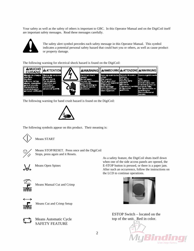
Your safety as well as the safety of others is important to GBC. In this Operator Manual and on the DigiCoil itselfare important safety messages. Read these messages carefully.
The safety alert symbol precedes each safety message in this Operator Manual. This symbolindicates a potential personal safety hazard that could hurt you or others, as well as cause productor property damage.
The following warning for electrical shock hazard is found on the DigiCoil:
The following warning for hand crush hazard is found on the DigiCoil:
The following symbols appear on this product. Their meaning is:
Means START
Means STOP/RESET. Press once and the DigiCoilStops, press again and it Resets.
Means Open Spines
Means Manual Cut and Crimp
Means Cut and Crimp Setup
Means Automatic CycleSAFETY FEATURE
As a safety feature, the DigiCoil shuts itself downwhen one of the side access panels are opened, theE-STOP button is pressed, or there is a paper jam.After such an occurrence, follow the instructions onthe LCD to continue operations.
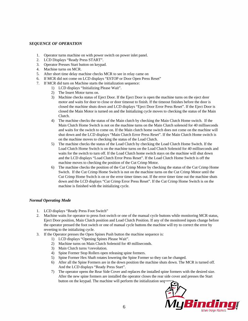
ESTOP Switch – located on thetop of the unit. Red in color.ccolor.

3
FOR YOUR SAFETY
• Do not connect the DigiCoil to electrical power orattempt to operate it before you read this OperatorManual and have been fully trained to operate it.
• Save this Operator Manual for later use.• Keep hands, long hair, neckties, necklaces and
other loose articles away from moving parts.• Never override or attempt to defeat electrical or
mechanical interlock devices. Machine will notoperate normally when covers are removed.
• Do not insert objects or spill liquids into theDigiCoil. They may contact dangerous voltage orshort out components that may result in fire orelectric shock.
• Only connect the DigiCoil to the electrical supplyshown in the machine specification section of theOperator Manual and the serial/rating label locatedon the equipment. Connect to a socket-outletinstalled near the product that is easily accessible.
• Do not alter the plug on the end of the cord set (ifprovided) of the DigiCoil. It was selected for yoursafety.
• Connect the plug only to a matching receptacle. Ifyou do not have such a receptacle, contact aqualified electrician to have one installed.
• Turn the DigiCoil power “Off” (O) at the end of theday.
• Unplug the DigiCoil before moving it or when itwill not in use for an extended period of time.
• Do not attempt to service the DigiCoil. Contact anauthorized GBC service representative if any of theconditions listed below are encountered:• Damaged plug or frayed power cord.• If liquid has been spilled into the product.• If the product has been exposed to rain or
water.• If the product has been dropped, bumped or
dented.
FCC NOTE: This equipment has been tested andfound to comply with the limits for a Class A digitaldevice, pursuant to part 15 of the FCC Rules. Theselimits are designed to provide reasonable protectionagainst harmful interference when the equipment is in acommercial environment. This equipment generates,uses, can radiate radio frequency energy and, if notinstalled and used in accordance with the OperatorManual, may cause harmful interference to radiocommunications. Operation of this equipment in aresidential area is likely to cause harmful interference inwhich case the user will be required to correct theinterference at his/her own expense.
This device complies with part 15 of the FCC Rules.Operation is subject to the following two conditions: (1)This device may not cause harmful interference, and (2)this device must accept any interference receivedincluding interference that may cause undesired
operation.
CAUTION: CHANGES OR MODIFICATIONS NOTEXPRESSLY APPROVED BY GENERAL BINDINGCORPORATION COULD VOID YOURAUTHORITY TO OPERATE THE EQUIPMENT.
Department of Communications (CANADA)Note: This Class A digital apparatus meets allrequirements of the Canadian Interference-CausingEquipment Regulations.
Cet appareil numérique de la classe A respecte toutes lesexigences du Règlement sur le matériel brouiller duCanada
MAIN CORDSET SELECTION (FOR 230VACMACHINE ONLY)
CAUTION: WHEN CHOOSING ADETACHABLE LINE CORD FOR USEWITH THE DIGICOIL, ALWAYS
OBSERVE THE FOLLOWING PRECAUTIONS:
The cordset consists of three components; theattachment plug, cordage and appliance inlet. Each ofthese must have European regulatory approvals forsafety.
The following minimum electrical ratings for thespecific cordset are published for safety purposes. DONOT USE CORDSETS THAT DO NOT MEET THEFOLLOWING MINIMUM ELECTRICALREQUIREMENTS.
PLUG: 480 amperes, 250 volts, 50/60 Hz, Class 1, 3conductor, European safety approved.
CORDAGE: Type HO3VV-F3G0.75, Harmonized(+HAR+). The “++” symbols indicate cordageapproved to appropriate European standard (Note:“HAR” may be substituted for approval mark ofEuropean safety agency which approved the cordage.An example would be “+VDE+”.
APPLIANCE CONNECTOR: 480A, 250 volts, 50/60Hz, European safety approved. Type IEC 320. Cord-setshall not exceed 3 meters in length. Cord-set with

4
component electrical ratings greater than the minimumspecified electrical ratings may be substituted
4
1. SPECIFICATIONS
Use this section to determine proper installation requirements as well as the capabilities of the DIGICOIL.
Sheet Size: 4.25” x 5” to 14.5” x 12” 108mm x 127mm to 368.3mm x 304.8mm
Holes: Holes in paper should be made with a 4:1, 0.2475pitch, over-sized oval -shaped punching tool ONLY
Coil Size: From 8mm diameter up to 33mm diameter 4:1 GBCPlastic Coil
Coil Length: From 5” (127mm) to 16.25” (412.75mm)
Productivity: 10mm coil - up to 450 documents per hour30mm coil – up to 250 documents per hour(Times depend on element length, documentpunching quality, but most importantly operatorproficiency)
Machine Weight: 275lbs. (125kg) est.
Dimensions: 48”D x 48”W x 60”H121.92cm x 121.92cm x 152.4cm
Electrical Power: 115V AC, 60Hz, 4 amps, 480 Watts
Short Circuit Interrupt Capacity: 2000A
Ambient Air Temperature: 5° - 40° C
Humidity Rating: 30% - 95% (non-condensing)
Year of Manufacture: 2000
5
2. INSTALLATION PROCEDURE
Use this section to properly unpack, set into place, and prepare DIGICOIL for set up.
Inspect the shipping container for any visible damage while the trucking company is still there. Ifyou see any damage, immediately file a damage claim with that trucking company. Otherwise youmay be responsible for any needed repairs.
1. Unpacking1) Remove wood screws on top of crate to remove crate top.
2) Remove front of crate and either adjacent side of crate also fastened by wood screws.3) Use a 5/8” Allen wrench to remove the bolts holding the DIGICOIL to the pallet. The
bolts are located near the casters.4) Slide the DIGICOIL off the pallet and onto the floor.
2. Locate foot pedal secured to the shipping skid. Hook up air tube for the foot pedal intofixture located underneath machine at opposite end of the control panel.
3. Slide on paper jogging tray with binding element size guide to front cover near the controlpanel using the two t-slot holes.
4. Slide on output tray using the four t-slot holes onto the output end of the machine.5. Locate the spine formers that are bolted together and packaged in a separate box. Unpack
and place the Spine Formers on the holder inside the machine.6. Have your electrician hook up the appropriate power requirements listed in the specifications
section of this manual. CAUTION: DO NOT APPLY POWER TO THEDIGICOIL!! A GBC technician will check to insure proper power is present wheninstallation is scheduled. YOU WILL VOID YOUR WARRANTY IF YOU APPLYPOWER.
7. Be sure that you have COLOR COIL SUPPLIES and enough pre-punched books to run yourmachine for at least one hour. Please contact your sales representative if you have any supplyneeds.
8. Contact GBC National service to schedule a technician to complete your installation.
3. THEORY OF OPERATION
6
SEQUENCE OF OPERATION
1. Operator turns machine on with power switch on power inlet panel.2. LCD Displays “Ready Press START”.3. Operator Presses Start button on keypad.4. Machine turns on MCR.5. After short time delay machine checks MCR to see in relay came on6. If MCR did not come on LCD displays “ESTOP or Door Open Press Reset”7. If MCR did turn on Machine starts the initialization sequence:
1) LCD displays “Initializing Please Wait”.2) The Insert Motor turns on.3) Machine checks status of Eject Door. If the Eject Door is open the machine turns on the eject door
motor and waits for door to close or door timeout to finish. If the timeout finishes before the door isclosed the machine shuts down and LCD displays “Eject Door Error Press Reset”. If the Eject Door isclosed the Main Motor is turned on and the Initializing cycle moves to checking the status of the MainClutch.
4) The machine checks the status of the Main clutch by checking the Main Clutch Home switch. If theMain Clutch Home Switch is not on the machine turns on the Main Clutch solenoid for 40 millisecondsand waits for the switch to come on. If the Main clutch home switch does not come on the machine willshut down and the LCD displays “Main Clutch Error Press Reset”. If the Main Clutch Home switch ison the machine moves to checking the status of the Load Clutch.
5) The machine checks the status of the Load Clutch by checking the Load Clutch Home Switch. If theLoad Clutch Home Switch is on the machine turns on the Load Clutch Solenoid for 40 milliseconds andwaits for the switch to turn off. If the Load Clutch home switch stays on the machine will shut downand the LCD displays “Load Clutch Error Press Reset”. If the Load Clutch Home Switch is off themachine moves to checking the position of the Cut Crimp Motor.
6) The machine checks the position of the Cut Crimp Motor by checking the status of the Cut Crimp HomeSwitch. If the Cut Crimp Home Switch is not on the machine turns on the Cut Crimp Motor until theCut Crimp Home Switch is on or the error timer times out. If the error timer time out the machine shutsdown and the LCD displays “Cut Crimp Error Press Reset”. If the Cut Crimp Home Switch is on themachine is finished with the initializing cycle.
Normal Operating Mode
1. LCD displays “Ready Press Foot Switch”2. Machine waits for operator to press foot switch or one of the manual cycle buttons while monitoring MCR status,
Eject Door position, Main Clutch position and Load Clutch Position. If any of the monitored inputs change beforethe operator pressed the foot switch or one of manual cycle buttons the machine will try to correct the error byreverting to the initializing cycle.
3. If the Operator presses the Open Spines Push button the machine sequence is:1) LCD displays “Opening Spines Please Wait”.2) Machine turns on Main Clutch Solenoid for 40 milliseconds.3) Main Clutch turns ½ revolution.4) Spine Former Stop Rollers open releasing spine formers.5) Spine Former Hex Shaft rotates lowering the Spine Former so they can be changed.6) After all the Spine Formers are in the down position the machine shuts down. The MCR is turned off.
And the LCD displays “Ready Press Start”.7) The operator opens the Rear Side Cover and replaces the installed spine formers with the desired size.
After the new spine formers are installed the operator closes the rear side cover and presses the Startbutton on the keypad. The machine will perform the initialization sequence.
7
4. If the Operator presses the Cut Crimp Manual button the machine sequence is:1) LCD displays “Cut Crimp Cycle Please Wait”.2) The machine turns on the Cut Crimp Motor.3) After the Cut Crimp Motor is turned on the machine monitors the Cut Crimp Home switch to ensure
that it left the home position.4) After ensuring that the Cut Crimp Home switch has left the home position the machine waits for the
switch to return home.5) When the Cut Crimp Home switch turns on again the Cut Crimp Motor turns off.6) LCD displays “Ready Press Foot Switch”.
5. If the Operator presses the Foot Switch the machine sequence is:1) Operator presses foot switch.2) LCD displays “Cycle Active”.3) The Load Clutch Solenoid is turned on for 40 milliseconds.4) The Load Clutch, rotates ½ turn lowering the Detect Arm. The chute is raised Ejecting any the previously
bound book. When the Load Clutch Home Switch changes state it indicates that the chute is fullyraised, The Main Motor turns off and the Eject Door cycles allow the book to exit.
5) When the Load Clutch Home switch changes state the machine checks the Coil Detect Switch.6) If the Coil Detect switch is on the Load Clutch Solenoid is turned on and the machine resets and waits
for the next foot switch actuation.7) If the Coil Detect Switch is not on the Insert Clutch is turned on.8) The Coil Detect Switch is monitored if it changes state in less than ¼ second the machine will shut
down and the LCD displays “Insert Error Press Reset”.9) If the Coil Detect Switch does not change state in 10 seconds the machine will shut down and the LCD
displays “Insert Error Press Reset”.10) When the Coil Detect Switch changes state the Insert Brake is turned on and the Insert Clutch is turned
off.11) The machine checks the status of the Eject Door and the Book at Cut Crimp Photo Eye. If the Eject
Door is open the machine waits for it to close before continuing. If the Book at Cut Crimp Photo Eye ison the machine shuts down and the LCD displays “Eject Error Press Reset”.
12) The Load Clutch Solenoid is turned on for 40 milliseconds raising the stripper bracket and the detectarm away from the book. The chute is also lowered to the down position. If the Load Clutch HomeSwitch does not change state the machine shuts down and the LCD displays “Load Clutch Error PressReset”.
13) After the Load Clutch Solenoid is turned off the Main Clutch Solenoid is turned on for 40 millisecondsopening the spine former rollers and lowering the Spine formers. This allows the book to drop to thechute. The Main Clutch Home Switch is monitored if it does not change state in ¼ second the machineshuts down and the LCD display “Main Clutch Jam Press Reset”.
14) The Book at Cut Crimp photo eye is monitored if the photo eye does not turn on within 2 seconds themachine shuts down and the LCD displays “Book Drop Error Press Reset”.
15) When the Book at Cut Crimp Photo Eye turns on a small settle time is allowed then the Main Clutch isturned on for 40 milliseconds. This raises the clamps and lets the book fall into the cut crimp knives.The Spine Formers are raised to the home position and the spine former rollers are closed. At this pointthe operator can load the next book. If the Main Clutch Home Switch does on come on within 1 secondafter the Main Clutch Solenoid is turned on the machine shuts down and the LCD displays “MainClutch Jam Press Reset”.
16) After a short settle time for the book to stop moving to the cutters the Cut Crimp Motor turns on. Afterthe Cut Crimp Motor is turned on the machine monitors the Cut Crimp Home switch to ensure that itleft the home position. The Cut Crimp Motor turns 1 revolution. This motion holds the coil and bends itaround the knife. When the coil is bent to 90 degrees the knife cuts the scrap from the end which falls tothe eject chute.
17) After ensuring that the Cut Crimp Home switch has left the home position the machine waits for theswitch to return home.
18) When the Cut Crimp Home switch turns on again the Cut Crimp Motor turns off.19) The bound book is left on the chute to be ejected during the next cycle.20) LCD displays “Ready Press Foot Switch” unless the Auto Cycle Mode is used.

8
21) If the Auto Cycle Mode is used the LCD displays “Cycle Active”. The machine will wait for the AutoCycle Delay to complete then automatically start the next machine cycle.
6. If the Operator presses the Cut Crimp Setup button the machine will cycle normally to the point where the bookdrops to the chute then ask the operator to check the position of the cutters before finishing the cycle. After theoperator is satisfied with the position of the cutters he will press the foot switch to continue the cycle.
7. If the Operator presses the Auto cycle button the machine will start normally when the operator presses the footswitch. After the machine finishes the cycle. The machine will wait for the Auto Cycle Delay to complete thenautomatically start the next machine cycle. If the operator fails to have the next coil in the Coil Loading Bracketthe machine will reset the Load Clutch Solenoid and wait for the next foot switch operation.
4. FUNCTIONAL PARTS DESCRIPTION
Power Switch
Located on the right side of the machine. This switchturns electrical power on and off by push switch. TheLCD information display will illuminate when power ison.
Emergency Stop Switch(ESTOP)The red switch located on the topof the DigiCoil. This switchshould be pressed immediatelyshould any emergency occur. Pressing this switch cutsoff power to the motors in emergency situations. Thisswitch is only for emergency situations.
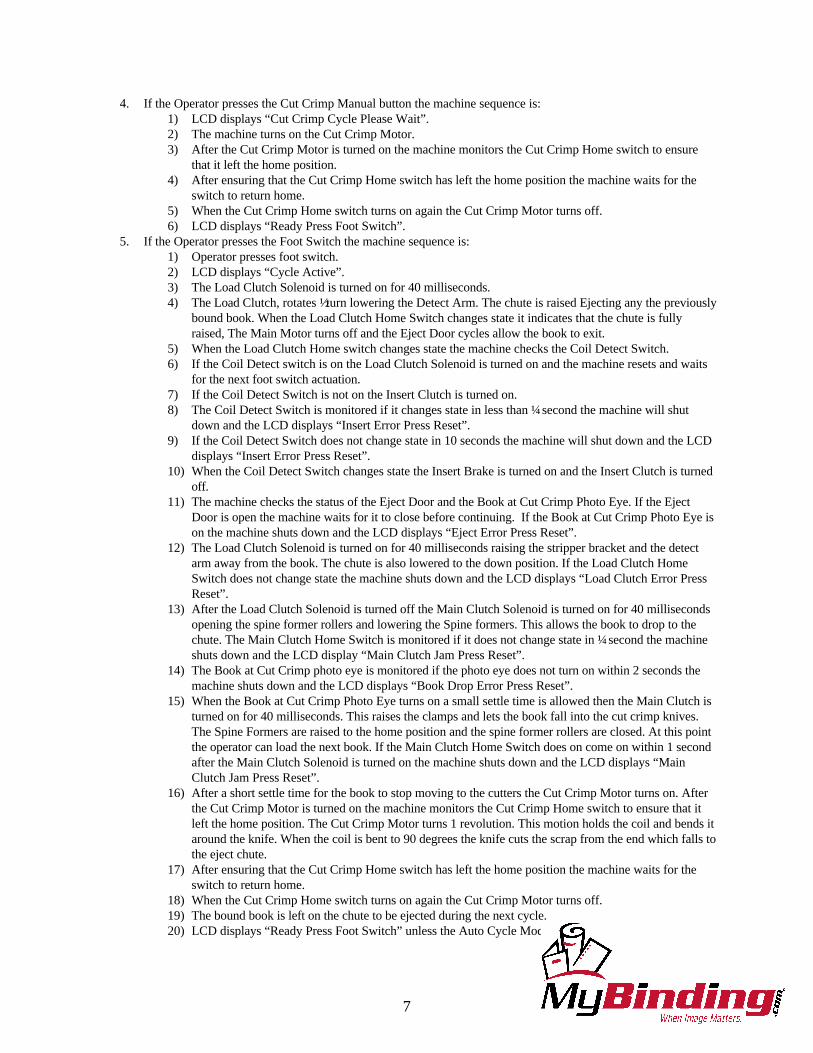
Keypad
Start Button: The green button on the Keypad.This button, when pressed, starts initial operations of themachine.
LCD Display: Located on the Keypad. The LCDdisplays the machine status and faults.
Open Spines Button: Located on the Keypad.When pressed, the Document Insertion Area opens andthe Spine Former Brackets lower.
Cut Crimp Manual Button: Located on theKeypad. When pressed, the knives will cut and crimpthe properly placed document’s plastic coil.
Cut Crimp Setup Button: Located on theKeypad. When pressed, the machine will insert the coilinto the document and the document is dropped down tothe Cut/Crimp station where the cycle ends for knifeadjustments.
Auto Cycle Button: Located on the Keypad. Whenpressed, the machine will automatically complete eachbinding cycle until there is no longer a coil present onthe Coil Driver area. The delay time is variable.
Stop/Reset Button: Located on the Keypad. Whenpressed, the machine will power down and reset itself.
Service Arrows: Located on the Keypad. These are forGBC Certified Service Technicians, and will produce no
effect when a user presses them – unless the operator issetting the Auto Cycle Timer.
Staging Shelf
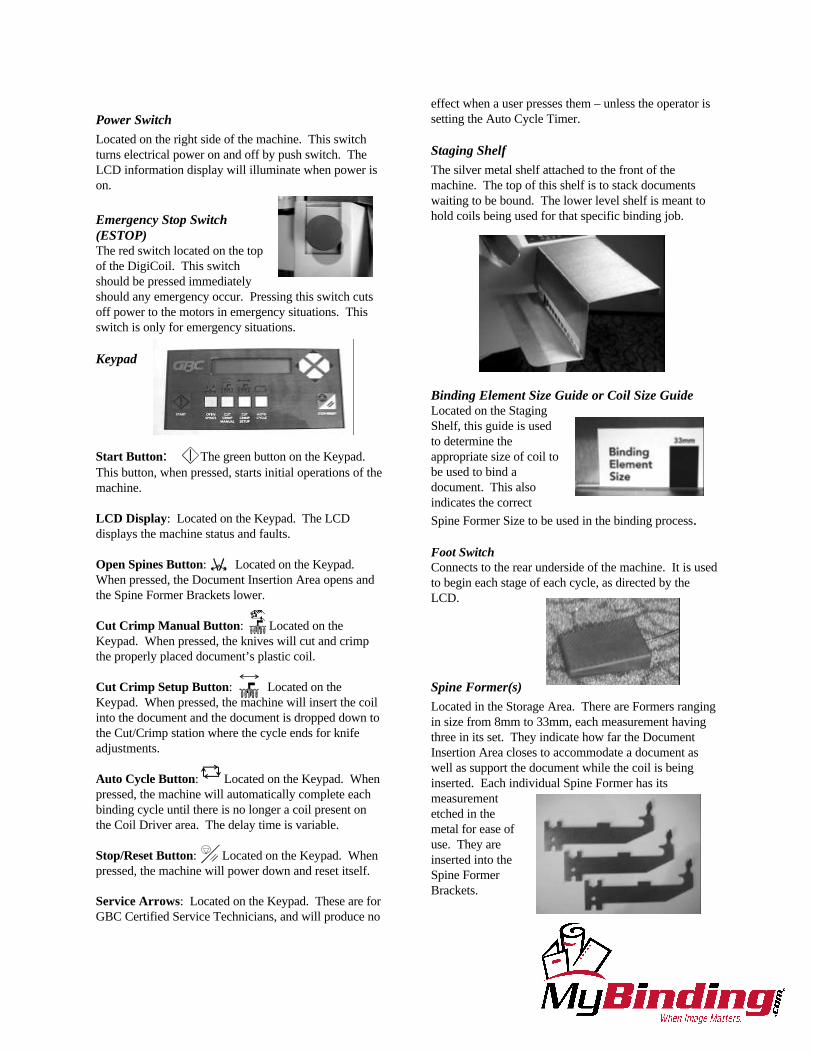
The silver metal shelf attached to the front of themachine. The top of this shelf is to stack documentswaiting to be bound. The lower level shelf is meant tohold coils being used for that specific binding job.
Binding Element Size Guide or Coil Size GuideLocated on the StagingShelf, this guide is usedto determine theappropriate size of coil tobe used to bind adocument. This alsoindicates the correct
Spine Former Size to be used in the binding process.
Foot SwitchConnects to the rear underside of the machine. It is usedto begin each stage of each cycle, as directed by theLCD.
Spine Former(s)
Located in the Storage Area. There are Formers rangingin size from 8mm to 33mm, each measurement havingthree in its set. They indicate how far the DocumentInsertion Area closes to accommodate a document aswell as support the document while the coil is beinginserted. Each individual Spine Former has itsmeasurementetched in themetal for ease ofuse. They areinserted into theSpine FormerBrackets.
10
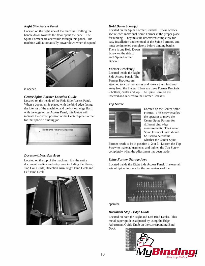
Right Side Access Panel
Located on the right side of the machine. Pulling thehandle down towards the floor opens the panel. TheSpine Formers are accessible through this panel. Themachine will automatically power down when this panel
is opened.
Center Spine Former Location GuideLocated on the inside of the Ride Side Access Panel.When a document is placed with the bind edge facingthe interior of the machine, and the bottom edge flushwith the edge of the Access Panel, this Guide willindicate the correct position of the Center Spine Formerfor that specific binding job.
Document Insertion Area
Located on the top of the machine. It is the entiredocument loading and setup area including the Platen,Top Coil Guide, Detection Arm, Right Bind Deck andLeft Bind Deck.
Hold Down Screw(s)Located on the Spine Former Brackets. These screwssecure each individual Spine Former in the proper placefor binding. They must be unscrewed completely foreasy installation and removal of the Spine Formers, andmust be tightened completely before binding begins.There is one Hold DownScrew on the side ofeach Spine FormerBracket.
Former Bracket(s)Located inside the RightSide Access Panel. TheFormer Brackets areattached to a bar that raises and lowers them into andaway from the Platen. There are three Former Brackets– bottom, center and top. The Spine Formers areinserted and secured to the Former Brackets.
Top Screw
Located on the Center SpineFormer. This screw enablesthe operator to move theCenter Spine Former fordifferent bind edgemeasurements. The CenterSpine Former Guide shouldbe used to determinewhether the Center Spine
Former needs to be in position 1, 2 or 3. Loosen the TopScrew to make adjustments, and tighten the Top Screwcompletely when the adjustment has been made.
Spine Former Storage Area
Located inside the Right Side Access Panel. It stores allsets of Spine Formers for the convenience of the
operator.
Document Stop / Edge Guide
Located on both the Right and Left Bind Decks. Thismetal paper guide is adjusted by using the EdgeAdjustment Guide Knob on the corresponding BindDeck.
11
Edge Adjustment Guide Knob
Located on both the Right and Left Bind Decks. TheKnob is used to adjust the paper/document placementagainst the Platen.
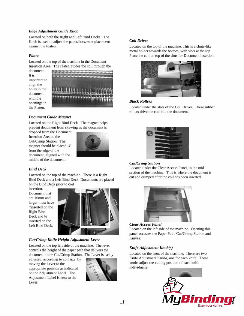
Platen
Located on the top of the machine in the DocumentInsertion Area. The Platen guides the coil through thedocument.It isimportant toalign theholes in thedocumentwith theopenings inthe Platen.
Document Guide Magnet
Located on the Right Bind Deck. The magnet helpsprevent document from skewing as the document isdropped from the DocumentInsertion Area to theCut/Crimp Station. Themagnet should be placed ¼”from the edge of thedocument, aligned with themiddle of the document.
Bind Deck
Located on the top of the machine. There is a RightBind Deck and a Left Bind Deck. Documents are placedon the Bind Deck prior to coilinsertion.Document thatare 16mm andlarger must have½ inserted on theRight BindDeck and ½inserted on theLeft Bind Deck.
Cut/Crimp Knife Height Adjustment Lever
Located on the top left side of the machine. The levercontrols the height of the paper path that delivers thedocument to the Cut/Crimp Station. The Lever is easilyadjusted, according to coil size, bymoving the Lever to theappropriate position as indicatedon the Adjustment Label. TheAdjustment Label is next to theLever.
Coil Driver
Located on the top of the machine. This is a chute-likemetal holder towards the bottom, with slots at the top.Place the coil on top of the slots for Document insertion.
Black Rollers
Located under the slots of the Coil Driver. These rubberrollers drive the coil into the document.
Cut/Crimp StationLocated under the Clear Access Panel, in the mid-section of the machine. This is where the document iscut and crimped after the coil has been inserted.
Clear Access PanelLocated on the left side of the machine. Opening thispanel accesses the Paper Path, Cut/Crimp Station andKnives.
Knife Adjustment Knob(s)
Located on the front of the machine. There are twoKnife Adjustment Knobs, one for each knife. Theseknobs adjust the cutting position of each knifeindividually.
12
Output Stacker
Located at the far-left side of the machine. Finisheddocuments are ejected into the Output Stacker. TheStacker must be emptied regularly to prevent jams.
Top Coil Guide Bar
Located in the middle of the Document Insertion Area.This is a metal roller bar that assists in the guidance ofthe coil.
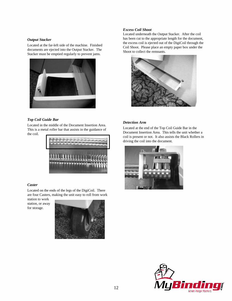
Caster
Located on the ends of the legs of the DigiCoil. Thereare four Casters, making the unit easy to roll from workstation to workstation, or awayfor storage.
Excess Coil ShootLocated underneath the Output Stacker. After the coilhas been cut to the appropriate length for the document,the excess coil is ejected out of the DigiCoil through theCoil Shoot. Please place an empty paper box under theShoot to collect the remnants.
Detection Arm
Located at the end of the Top Coil Guide Bar in theDocument Insertion Area. This tells the unit whether acoil is present or not. It also assists the Black Rollers indriving the coil into the document.

13
5. DIGICOIL SET-UP
Turning the DigiCoil On:1. Plug the blunt end of the Power Cord into the DigiCoil unit, just below the Power Switch.2. Plug the end of the Power Cord that has metal prongs into a standard outlet.3. Press the Power Switch to “O’ for ON.4. The LCD on the Keypad will read “Ready Press Start”.
Determining the Appropriate Coil Size
1. Place the complete document to be bound on the lower level of the staging shelf so that the binding edge is against theBinding Element Size Guide bar graph. The staging shelf is the metal shelving attached to the front of the DigiCoil.
2. Select the coil size that best lines up with your document thickness. It is important the document fits easily within therange of the bar that you determine to be the appropriate coil size. If it does not, you will need to either go to the nextlarger size of coil, or down to the next smaller size.
3. The coil size you have selected for your document is also the Spine Former size you will need to bind the documents.4. Size of Coil = Size of Spine Formers.
Changing / Inserting the Spine Formers
1. After determining the correct coil and Spine Former size, press the Start button, and after a brief warm-up period, theLCD panel will read “Ready Press Foot Switch”.
2. Press the Open Spines button.3. The Document Insertion Area will open, the Spine Formers will lower, and the unit will power down.4. Open the Right Side Access Panel of the unit to gain full and easy access to the Spine Formers.5. Remove the Spine Formers currently in the unit by loosening the Hold Down Screws. If there are no Spine Formers
installed in the unit, go to Step 9.6. Loosen the Hold Down Screws until they stop in the full open position.7. Remove all three Spine Formers one at a time by rotating the top edge out first.8. Place the Formers in the convenient Storage Area.9. Select the three new Formers according to the size stamped on each Former. All Formers and coils are measured in
millimeters.10. To insert the Former, turn it sideways, placing the bottom edge in first, and rotate into position.11. Tighten the Hold Down Screw until the Former is flat against the Former Bracket.12. Repeat this process for the two remaining Spine Formers.
Adjusting the Center Spine Former for Document Height
The bottom Former and the top Former do not move, their positions are fixed. The center Former position is the onlyFormer position that may need to be adjusted. The center Former has three different positions based on the height of thebind edge. The inside of the Right Side Access Panel door has a reference chart to assist in the proper placement of thecenter Spine Former, either position 1, 2, or 3.1. Place your document flush against the bottom edge of the panel door, positioned so the binding edge is parallel to the
inside of the machine.2. Check the placement of the top of the document on the Center Spine Former Location Guide. Whichever column the
top lies in is the position the center Former will need to be located.3. To move the location of the center former, completely loosen the Top Screw.4. Slide the bracket to the appropriate, marked position as indicated by the reference chart.5. Tighten the Top Screw completely when properly positioned. It is very important to align the Top Screw directly
into the hole.6. Close the Right Side Access Panel.7. Press Start. The DigiCoil will power up and the Document Insertion Area will close.
14
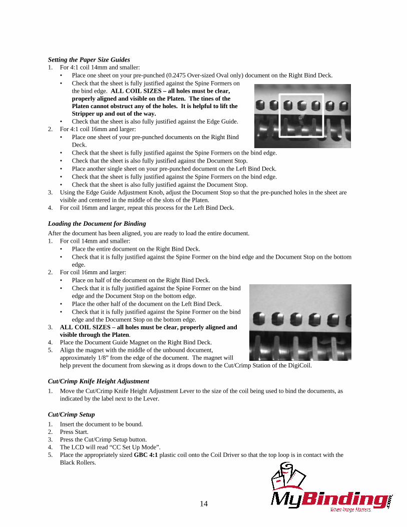
Setting the Paper Size Guides1. For 4:1 coil 14mm and smaller:
• Place one sheet on your pre-punched (0.2475 Over-sized Oval only) document on the Right Bind Deck.• Check that the sheet is fully justified against the Spine Formers on
the bind edge. ALL COIL SIZES – all holes must be clear,properly aligned and visible on the Platen. The tines of thePlaten cannot obstruct any of the holes. It is helpful to lift theStripper up and out of the way.
• Check that the sheet is also fully justified against the Edge Guide.2. For 4:1 coil 16mm and larger:
• Place one sheet of your pre-punched documents on the Right BindDeck.
• Check that the sheet is fully justified against the Spine Formers on the bind edge.• Check that the sheet is also fully justified against the Document Stop.• Place another single sheet on your pre-punched document on the Left Bind Deck.• Check that the sheet is fully justified against the Spine Formers on the bind edge.• Check that the sheet is also fully justified against the Document Stop.
3. Using the Edge Guide Adjustment Knob, adjust the Document Stop so that the pre-punched holes in the sheet arevisible and centered in the middle of the slots of the Platen.
4. For coil 16mm and larger, repeat this process for the Left Bind Deck.
Loading the Document for Binding
After the document has been aligned, you are ready to load the entire document.1. For coil 14mm and smaller:
• Place the entire document on the Right Bind Deck.• Check that it is fully justified against the Spine Former on the bind edge and the Document Stop on the bottom
edge.2. For coil 16mm and larger:
• Place on half of the document on the Right Bind Deck.• Check that it is fully justified against the Spine Former on the bind
edge and the Document Stop on the bottom edge.• Place the other half of the document on the Left Bind Deck.• Check that it is fully justified against the Spine Former on the bind
edge and the Document Stop on the bottom edge.3. ALL COIL SIZES – all holes must be clear, properly aligned and
visible through the Platen.4. Place the Document Guide Magnet on the Right Bind Deck.5. Align the magnet with the middle of the unbound document,
approximately 1/8” from the edge of the document. The magnet willhelp prevent the document from skewing as it drops down to the Cut/Crimp Station of the DigiCoil.
Cut/Crimp Knife Height Adjustment
1. Move the Cut/Crimp Knife Height Adjustment Lever to the size of the coil being used to bind the documents, asindicated by the label next to the Lever.
Cut/Crimp Setup
1. Insert the document to be bound.2. Press Start.3. Press the Cut/Crimp Setup button.4. The LCD will read “CC Set Up Mode”.5. Place the appropriately sized GBC 4:1 plastic coil onto the Coil Driver so that the top loop is in contact with the
Black Rollers.
15
6. Press the Foot Switch – the DigiCoil will insert the coil into the document and drop the Document to the Cut/CrimpStation.
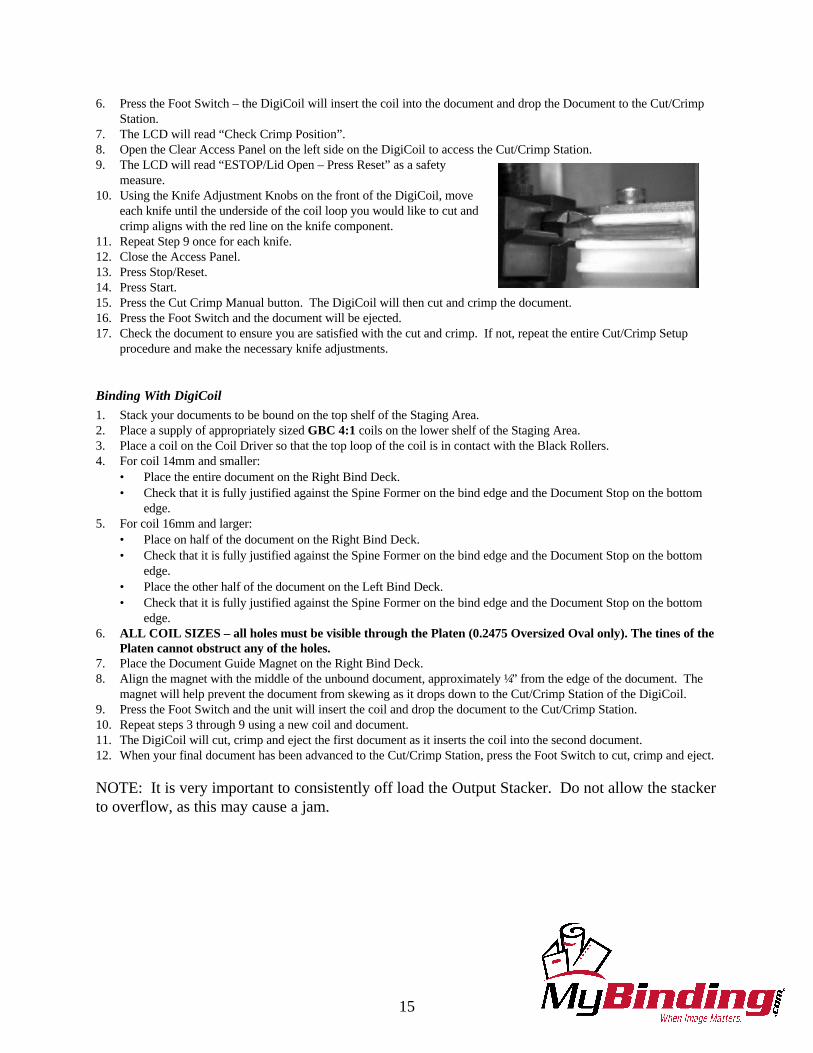
7. The LCD will read “Check Crimp Position”.8. Open the Clear Access Panel on the left side on the DigiCoil to access the Cut/Crimp Station.9. The LCD will read “ESTOP/Lid Open – Press Reset” as a safety
measure.10. Using the Knife Adjustment Knobs on the front of the DigiCoil, move
each knife until the underside of the coil loop you would like to cut andcrimp aligns with the red line on the knife component.
11. Repeat Step 9 once for each knife.12. Close the Access Panel.13. Press Stop/Reset.14. Press Start.15. Press the Cut Crimp Manual button. The DigiCoil will then cut and crimp the document.16. Press the Foot Switch and the document will be ejected.17. Check the document to ensure you are satisfied with the cut and crimp. If not, repeat the entire Cut/Crimp Setup
procedure and make the necessary knife adjustments.
Binding With DigiCoil
1. Stack your documents to be bound on the top shelf of the Staging Area.2. Place a supply of appropriately sized GBC 4:1 coils on the lower shelf of the Staging Area.3. Place a coil on the Coil Driver so that the top loop of the coil is in contact with the Black Rollers.4. For coil 14mm and smaller:
• Place the entire document on the Right Bind Deck.• Check that it is fully justified against the Spine Former on the bind edge and the Document Stop on the bottom
edge.5. For coil 16mm and larger:
• Place on half of the document on the Right Bind Deck.• Check that it is fully justified against the Spine Former on the bind edge and the Document Stop on the bottom
edge.• Place the other half of the document on the Left Bind Deck.• Check that it is fully justified against the Spine Former on the bind edge and the Document Stop on the bottom
edge.6. ALL COIL SIZES – all holes must be visible through the Platen (0.2475 Oversized Oval only). The tines of the
Platen cannot obstruct any of the holes.7. Place the Document Guide Magnet on the Right Bind Deck.8. Align the magnet with the middle of the unbound document, approximately ¼” from the edge of the document. The
magnet will help prevent the document from skewing as it drops down to the Cut/Crimp Station of the DigiCoil.9. Press the Foot Switch and the unit will insert the coil and drop the document to the Cut/Crimp Station.10. Repeat steps 3 through 9 using a new coil and document.11. The DigiCoil will cut, crimp and eject the first document as it inserts the coil into the second document.12. When your final document has been advanced to the Cut/Crimp Station, press the Foot Switch to cut, crimp and eject.
NOTE: It is very important to consistently off load the Output Stacker. Do not allow the stackerto overflow, as this may cause a jam.

16
Auto Cycle
Pressing the Auto Cycle button activates the Auto Cycle feature on the DigiCoil. By doing this, the operator eliminates theuse of the Foot Switch. The unit automatically runs the complete cycle after a timed delay. The time of the delay isvariable from 0-10 seconds and is set by the operator using the Keypad. If no coil is present when the Detection Arm goesdown, the machine will reset itself to normal operational mode. The operator may resume binding by pressing Start or byusing the Foot Switch, but the Auto Cycle button must be pressed again to re-activate the automatic cycling.
1. Press the Auto Cycle button.2. Load the coil.3. Load the document.4. Press the Foot Switch to start the Auto Cycle.5. Repeat Steps 2 and 3 until all documents have been bound.6. Press the Foot Switch to eject the final document.
To change the timed delay of the Auto Cycle Mode:1. Press Reset.2. The LCD will read “Ready Press Start”.3. Press the Up arrow on the Keypad and hold until the LCD shows the current setting of the Auto Cycle Delay in
seconds.4. Press the Down service arrow to scroll through settings 0 – 10. Stop pressing the Down arrow key when the
desired delay appears on the LCD.5. Press and hold the Up arrow until the LCD reads “Ready Press Start”.