gdj - lesman · title: gdj author: elster kromschröder subject: gas pressure regulator created...
TRANSCRIPT

2 Edition 08.12Technical Information · GB
• Universal pressure regulator for gaseous media• Design with inlet pressure compensation diaphragm ensures
high control accuracy• Internal impulse• No breather line required• EC type-tested and certified• Certified by Gosstandart pursuant to GOST-TR
Gas pressure regulator GDJ

GDJ · Edition 08.12 2▼ = To be continued
ContentsGas pressure regulator GDJ . . . . . . . . . . . . . . . . . . . . . . . . 1Contents . . . . . . . . . . . . . . . . . . . . . . . . . . . . . . . . . . . . . . . . 21 Application . . . . . . . . . . . . . . . . . . . . . . . . . . . . . . . . . . . . . 31.1 Examples of application. . . . . . . . . . . . . . . . . . . . . . . . . . 4
2 Certification . . . . . . . . . . . . . . . . . . . . . . . . . . . . . . . . . . . . 53 Function . . . . . . . . . . . . . . . . . . . . . . . . . . . . . . . . . . . . . . . 64 Flow rate . . . . . . . . . . . . . . . . . . . . . . . . . . . . . . . . . . . . . . 75 Selection . . . . . . . . . . . . . . . . . . . . . . . . . . . . . . . . . . . . . . 85.1 Type code . . . . . . . . . . . . . . . . . . . . . . . . . . . . . . . . . . . . . 8
6 Project planning information . . . . . . . . . . . . . . . . . . . . . . 96.1 Installation . . . . . . . . . . . . . . . . . . . . . . . . . . . . . . . . . . . . 96.2 Installation to EN 746-2. . . . . . . . . . . . . . . . . . . . . . . . . . 9
7 Technical data . . . . . . . . . . . . . . . . . . . . . . . . . . . . . . . . . 107.1 Dimensions. . . . . . . . . . . . . . . . . . . . . . . . . . . . . . . . . . . .117.2 Data table . . . . . . . . . . . . . . . . . . . . . . . . . . . . . . . . . . . .117.3 Spring table . . . . . . . . . . . . . . . . . . . . . . . . . . . . . . . . . . 12
8 Maintenance cycles . . . . . . . . . . . . . . . . . . . . . . . . . . . . 13Feedback . . . . . . . . . . . . . . . . . . . . . . . . . . . . . . . . . . . . . . 14Contact . . . . . . . . . . . . . . . . . . . . . . . . . . . . . . . . . . . . . . . . 14

GDJ · Edition 08.12 3
1 Application
GDJ 25
The spring-loaded gas pressure regulator GDJ with inlet pres-sure compensation diaphragm and zero shut-off serves to maintain the set outlet pressure constant despite changing gas flow rates and inlet pressures in gas pipelines. Thanks to an additional safety diaphragm, no breather line is required.For controlling the pressure of the gas and air supply to gas burners and gas appliances in industry and the heating sector.

GDJ · Edition 08.12 4
1 .1 Examples of application
Bogie hearth furnace
Roller hearth furnace
Bogie hearth furnace
Application

GDJ · Edition 08.12 5
2 CertificationEC type-tested and certified
pursuant to– Gas Appliances Directive (2009/142/EC) in conjunction
with DIN EN 88.
Approval for Russia
Certified by Gosstandart pursuant to GOST-TR.Approved by Rostekhnadzor (RTN).Scan of the approval for Russia (RUS) – see www.docuthek.com ➔ Elster Kromschröder ➔ Products ➔ 02 Pressure regulators ➔ Gas pressure regulators GDJ ➔ Kind of document: Certificate ➔ GDJ B00093 (nationales Zertifikat Russland) (RUS).
GDJ · Edition 08.12 6
GDJ 25
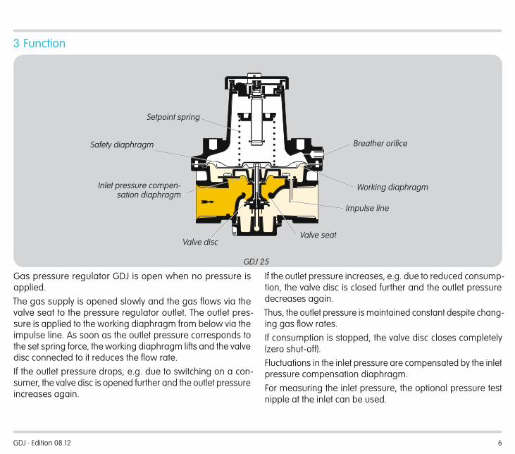
3 Function
Inlet pressure compen-sation diaphragm
Setpoint spring
Impulse line
Safety diaphragm Breather orifice
Valve seatValve disc
Working diaphragm
Gas pressure regulator GDJ is open when no pressure is applied.The gas supply is opened slowly and the gas flows via the valve seat to the pressure regulator outlet. The outlet pres-sure is applied to the working diaphragm from below via the impulse line. As soon as the outlet pressure corresponds to the set spring force, the working diaphragm lifts and the valve disc connected to it reduces the flow rate. If the outlet pressure drops, e.g. due to switching on a con-sumer, the valve disc is opened further and the outlet pressure increases again.
If the outlet pressure increases, e.g. due to reduced consump-tion, the valve disc is closed further and the outlet pressure decreases again. Thus, the outlet pressure is maintained constant despite chang-ing gas flow rates.If consumption is stopped, the valve disc closes completely (zero shut-off).Fluctuations in the inlet pressure are compensated by the inlet pressure compensation diaphragm.For measuring the inlet pressure, the optional pressure test nipple at the inlet can be used.

GDJ · Edition 08.12 7
4 Flow rate
2
3
4568
4 5 6 7 8 9 10 20 30 40 7050 60 80 100 2001
5 6 7 8 10 20 30 40 50 60 80 100 2002
4 5 6 7 8 10 20 30 40 50 60 80 1004
4 5 6 7 8 10 20 30 40 50 60 80 1003 3
3
3
4
2
10
20
30
40506080100
200
300
400500
GDJ
15
GD
J 20
GD
J 25
GD
J 40
GD
J 50
Qn [m3/h]
∆p [m
bar]
P1
= natural gas (ρ = 0.80 kg/m3) = town gas (ρ = 0.64 kg/m3) = LPG (ρ = 2.01 kg/m3) = air (ρ = 1.29 kg/m3)
Example:Gas type: natural gas, flow rate Q = 70 m3/h, inlet pressure pu = 70 mbar, outlet pressure pd = 20 mbar, pressure loss ∆p = pu - pd = 50 mbar.The result is intersection P1. The next largest nominal size is selected: GDJ 40.At a pressure loss of ∆p = 50 mbar, the max. flow rate is Q max.: 95 m3/h, the min. flow rate is Qmin. derived from Qmin. = Qmax. x 10% = 9.5 m3/h.

GDJ · Edition 08.12 8
5 SelectionType R 04 -0 -4 LGDJ 15
GDJ 20
GDJ 25
GDJ 40
GDJ 50
= standard, = availableOrder exampleGDJ 40R04-4
5 .1 Type codeCode DescriptionGDJ Gas pressure regulator15, 20, 25, 40, 50 Nominal sizeR Rp internal thread04 pu max. 400 mbar-0-4
Without pressure test pointPressure test point at the inlet
L* For air only (without approval)
* If “none”, this letter is omitted.

GDJ · Edition 08.12 9
6 Project planning information6 .1 Installation
Installation position: spring dome pointing vertically upwards or to the side, not upside down.
> 20 mm
The gas pressure regulator GDJ must not be in contact with masonry. Minimum clearance 20 mm.Do not store or install the unit in the open air.
GFK
GDJ
Sealing material and dirt, e.g. thread cuttings, must not be allowed to get into the regulator housing.Install a filter (GFK) upstream of every system.
6 .2 Installation to EN 746-2
5 DN
In accordance with EN 746-2, a safety shut-off valve upstream of the gas pressure regulator and a safety relief valve are required for gas pressure control systems.These valves are not required if the highest possible operating pressure upstream of the regulator cannot exceed the maxi-mum allowable operating pressure of the downstream devices.
Safety shut-off valve JSAV
Pressure regulator GDJ
Safety relief valve VSBV

GDJ · Edition 08.12 10
7 Technical dataGas types: natural gas, town gas, LPG (gaseous) and biologi-cally produced methane (max. 0.02 %-by-vol. H2S), GDJ..L also for air. The medium must be dry in all temperature conditions and must not contain condensate.Inlet pressure range up to 400 mbar.Outlet pressure ranges: GDJ 15: 2 to 55 mbar, GDJ 20 – 40: 5 to 160 mbar, GDJ 50: 5 to 100 mbar.Control range: 10:1.Ambient temperature: -20 to +60°C.Storage temperature: -20 to +40°C.Valve housing: aluminium. Valve seat: aluminium.Valve disc: plastic.Valve disc seal: Perbunan.Diaphragms: Perbunan.When used for air: special version.Internal thread: Rp to ISO 7-1.

GDJ · Edition 08.12 11
7 .1 Dimensions
H1
H2L
D
7 .2 Data tableType Dimensions pu max. Weight
L H1 H2 DDN Connection mm mm mm mm mbar kg
GDJ 15 15 Rp ½ 100 90 30 100 400 0.6GDJ 20 25 Rp ¾ 125 132 34 134 400 1GDJ 25 40 Rp 1 125 132 34 134 400 1GDJ 40 40 Rp 1½ 155 149 45 185 400 1.9GDJ 50 50 Rp 2 200 167 52 234 400 3.1
GDJ 15 GDJ 20
H1
H2 L
D
Technical data

GDJ · Edition 08.12 12
Technical data
7 .3 Spring tableType Opening pressure
rangeSpring marking Order No.
mbarGDJ 15 2 – 16 yellow 03089075
10 – 20 black 0308907616 – 28* orange 0308907722 – 40 brown 03089078
40 – 55 light green/light blue 03089079
GDJ 20, 25 5 – 15 yellow 0308904812.5 – 25* black 0308904922.5 – 35 orange 0308905025 – 75 yellow/black 0308905170 – 100 pink/gold 0308905290 – 160 yellow/orange 03089056
GDJ 40 5 – 15 red/yellow 0308905312.5 – 25* red/black 0308905422.5 – 35 red/orange 0308905525 – 75 yellow/orange 0308905670 – 100 pink/silver 0308905790 – 160 grey/gold 03089062
GDJ 50 5 – 15 blue/yellow 0308905812.5 – 25* blue/black 0308905922.5 – 35 blue/orange 0308906025 – 75 yellow/dark green 0308906170 – 100 grey/gold 03089062
* Standard equipmentDispatch complete with label for changed outlet pressure.

GDJ · Edition 08.12 13
8 Maintenance cyclesAt least once a year, at least twice a year in the case of bio-logically produced methane.

GDJ · Edition 08.12
FeedbackFinally, we are offering you the opportunity to assess this “Technical Information (TI)” and to give us your opinion, so that we can improve our documents further and suit them to your needs.
ClarityFound information quicklySearched for a long timeDidn’t find informationWhat is missing?
ComprehensionCoherentToo complicatedNo answer
ScopeToo littleSufficientToo wideNo answer
No answer
NavigationI can find my way aroundI got “lost”No answer
UseTo get to know the productTo choose a productPlanningTo look for information
My scope of functionsTechnical departmentSalesNo answer
Remarks
(Adobe Reader 7 or higher required) www.adobe.com
Elster GmbH Postfach 2809 · 49018 Osnabrück Strotheweg 1 · 49504 Lotte (Büren) GermanyT +49 541 1214-0 F +49 541 1214-370 [email protected]
The current addresses of our international agents are available on the Internet:www.kromschroeder.de/index.php?id=718&L=1
We reserve the right to make technical modifications in the interests of progress.Copyright © 2012 Elster GmbH All rights reserved.
Contact
0325
1256
Contact
Feedback