gdt-true position
DESCRIPTION
GDT True PositionTRANSCRIPT

Application Seminar 2006
Geometric Dimensioning & Tolerancing
True Position
Carl Zeiss IMT GD&TApplication Seminar 2006
Page 2
GD&T
• Rules
• Use and effect of Material Condition Modifiers
• Datum Reference Frame mobility sources
• Comparison between the traditional and new methods

Carl Zeiss IMT GD&TApplication Seminar 2006
Page 3
GD&TEarlier generation software
“…. in early generation software packages, the result with MMC is identical to the result without MMC - the actual tolerance will be bigger than the original given tolerance, which means it is easier to be qualified for the evaluated object. So ….users will be happy with the result within the tolerance ….”

Carl Zeiss IMT GD&TApplication Seminar 2006
Page 4
GD&TUse and effect of MCMs
Material Condition Modifier (MCM) MMC/LMC/RFS are used to define the treatment of size deviations
MCM expand the tolerance zone depending on the considered feature and they mobilize the tolerance zone depending on the datum features
MCM for the considered featureM: expands the tolerance zoneS: size does not influence the tolerance zoneL: expands the tolerance zone
MCM for datum featuresM: gives mobility to the tolerance zoneS: means static tolerance zoneL: gives mobility to the tolerance zone
Mobility of the tolerance zone reduces the actual deviation

Carl Zeiss IMT GD&TApplication Seminar 2006
Page 5
GD&TUse and effect of MCMs
Material Condition Modifier (MCM) MMC/LMC/RFS are used to define the treatment of size deviations
MCM expand the tolerance zone depending on the considered feature and they mobilize the tolerance zone depending on the datum features
MCM for the considered featureM: expands the tolerance zoneS: size does not influence the tolerance zoneL: expands the tolerance zone
MCM for datum featuresM: gives mobility to the tolerance zoneS: means static tolerance zoneL: gives mobility to the tolerance zone
Mobility of the tolerance zone reduces the actual deviation

Carl Zeiss IMT GD&TApplication Seminar 2006
Page 6
GD&TUse and effect of MCMs
Material Condition Modifier (MCM) MMC/LMC/RFS are used to define the treatment of size deviations
MCM expand the tolerance zone depending on the considered feature and they mobilize the tolerance zone depending on the datum features
MCM for the considered featureM: expands the tolerance zoneS: size does not influence the tolerance zoneL: expands the tolerance zone
MCM for datum featuresM: gives mobility to the tolerance zoneS: means static tolerance zoneL: gives mobility to the tolerance zone
Mobility of the tolerance zone reduces the actual deviation

Carl Zeiss IMT GD&TApplication Seminar 2006
Page 7
GD&TUse and effect of MCMs
Material Condition Modifier (MCM) MMC/LMC/RFS are used to define the treatment of size deviations
MCM expand the tolerance zone depending on the considered feature and they mobilize the tolerance zone depending on the datum features
MCM for the considered featureM: expands the tolerance zoneS: size does not influence the tolerance zoneL: expands the tolerance zone
MCM for datum featuresM: gives mobility to the tolerance zoneS: means static tolerance zoneL: gives mobility to the tolerance zone
Mobility of the tolerance zone reduces the actual deviation

Carl Zeiss IMT GD&TApplication Seminar 2006
Page 8
GD&TUse and effect of MCMs
Material Condition Modifier (MCM) MMC/LMC/RFS are used to define the treatment of size deviations
MCM expand the tolerance zone depending on the considered feature and they mobilize the tolerance zone depending on the datum features
MCM for the considered featureM: expands the tolerance zoneS: size does not influence the tolerance zoneL: expands the tolerance zone
MCM for datum featuresM: gives mobility to the tolerance zoneS: means static tolerance zoneL: gives mobility to the tolerance zone
Mobility of the tolerance zone reduces the actual deviation
“Mobility” of the tolerance zone is
the freedom to perform a best fit to
attempt to accept the work piece.

Carl Zeiss IMT GD&TApplication Seminar 2006
Page 9
GD&TGeneral rules for the handling of DRFs
Längenmessabweichung E
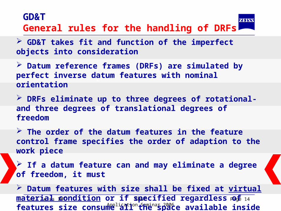
GD&T takes fit and function of the imperfect objects into consideration
Datum reference frames (DRFs) are simulated by perfect inverse datum features with nominal orientation
DRFs eliminate up to three degrees of rotational- and three degrees of translational degrees of freedom
The order of the datum features in the feature control frame specifies the order of adaption to the work piece
If a datum feature can and may eliminate a degree of freedom, it must
Datum features with size shall be fixed at virtual material condition or if specified regardless of features size consume all the space available in- or outside

Carl Zeiss IMT GD&TApplication Seminar 2006
Page 10
GD&TGeneral rules for the handling of DRFs
Längenmessabweichung E
GD&T takes fit and function of the imperfect objects into consideration
Datum reference frames (DRFs) are simulated by perfect inverse datum features with nominal orientation
DRFs eliminate up to three degrees of rotational- and three degrees of translational degrees of freedom
The order of the datum features in the feature control frame specifies the order of adaption to the work piece
If a datum feature can and may eliminate a degree of freedom, it must
Datum features with size shall be fixed at virtual material condition or if specified regardless of features size consume all the space available in- or outside

Carl Zeiss IMT GD&TApplication Seminar 2006
Page 11
GD&TGeneral rules for the handling of DRFs
Längenmessabweichung E
GD&T takes fit and function of the imperfect objects into consideration
Datum reference frames (DRFs) are simulated by perfect inverse datum features with nominal orientation
DRFs eliminate up to three degrees of rotational- and three degrees of translational degrees of freedom
The order of the datum features in the feature control frame specifies the order of adaption to the work piece
If a datum feature can and may eliminate a degree of freedom, it must
Datum features with size shall be fixed at virtual material condition or if specified regardless of features size consume all the space available in- or outside

Carl Zeiss IMT GD&TApplication Seminar 2006
Page 12
GD&TGeneral rules for the handling of DRFs
Längenmessabweichung E
GD&T takes fit and function of the imperfect objects into consideration
Datum reference frames (DRFs) are simulated by perfect inverse datum features with nominal orientation
DRFs eliminate up to three degrees of rotational- and three degrees of translational degrees of freedom
The order of the datum features in the feature control frame specifies the order of adaption to the work piece
If a datum feature can and may eliminate a degree of freedom, it must
Datum features with size shall be fixed at virtual material condition or if specified regardless of features size consume all the space available in- or outside

Carl Zeiss IMT GD&TApplication Seminar 2006
Page 13
GD&TGeneral rules for the handling of DRFs
Längenmessabweichung E
GD&T takes fit and function of the imperfect objects into consideration
Datum reference frames (DRFs) are simulated by perfect inverse datum features with nominal orientation
DRFs eliminate up to three degrees of rotational- and three degrees of translational degrees of freedom
The order of the datum features in the feature control frame specifies the order of adaption to the work piece
If a datum feature can and may eliminate a degree of freedom, it must
Datum features with size shall be fixed at virtual material condition or if specified regardless of features size consume all the space available in- or outside
Carl Zeiss IMT GD&TApplication Seminar 2006
Page 14
GD&TGeneral rules for the handling of DRFs
Längenmessabweichung E
GD&T takes fit and function of the imperfect objects into consideration
Datum reference frames (DRFs) are simulated by perfect inverse datum features with nominal orientation
DRFs eliminate up to three degrees of rotational- and three degrees of translational degrees of freedom
The order of the datum features in the feature control frame specifies the order of adaption to the work piece
If a datum feature can and may eliminate a degree of freedom, it must
Datum features with size shall be fixed at virtual material condition or if specified regardless of features size consume all the space available inside or outside

Carl Zeiss IMT GD&TApplication Seminar 2006
Page 15
GD&TExamples w/o MMC
Längenmessabweichung EA
BC
0,02 M A B M C M
Carl Zeiss IMT GD&TApplication Seminar 2006
Page 16
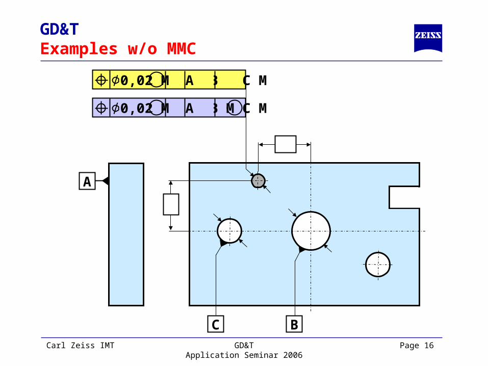
GD&TExamples w/o MMC
Längenmessabweichung EA
BC
0,02 M A B M C M
0,02 M A B M C M

Carl Zeiss IMT GD&TApplication Seminar 2006
Page 17
GD&TExamples w/o MMC
Längenmessabweichung EA
BC
0,02 M A B M C M
0,02 M A B M C M
0,02 M A B M C M

Carl Zeiss IMT GD&TApplication Seminar 2006
Page 18
GD&TExamples w/o MMC
Längenmessabweichung EA
BC
0,02 M A B M C M
0,02 M A B M C M
Incr
ea
sed
M
ob
ility
0,02 M A B M C M
Without best fit the distance
between datum features is
not taken into account!
This is the reason, why the
result with MMC sometimes
is larger than without (GO /
NO GO like a hard gage).

Carl Zeiss IMT GD&TApplication Seminar 2006
Page 19
GD&TDRF mobility sources
Datum features referenced with MMC or LMC
An inadequate number of datum features to eliminate all degrees of freedom
The second and all lower tiers of a composite feature control frame
Unstable datum features (e.g. convex reference plane)
0,1 A B C M
Static DRF
Highly mobile DRFSlightly mobile DRF
0,4 A B C 0,2 A B 0,1 A
C
B
A

Carl Zeiss IMT GD&TApplication Seminar 2006
Page 20
GD&TComparison between the methods
Early generation s/w method:
Alignment based on the datum features
MCM for the considered feature expands the tolerance zone
MCM for datum features expands the tolerance zone

Carl Zeiss IMT GD&TApplication Seminar 2006
Page 21
GD&TComparison between the methods
Correct Method (Calypso):
Best fit based on the previously described rules with a virtual gauge
MCM for the considered feature expands the tolerance zone
MCM for datum features gives mobility and does not expand the tolerance zone
Bestfit reduces the deviation of the actuals
Bestfit is limited by the MCM bonus
Traditional method:
Alignment based on the datum features
MCM for the considered feature expands the tolerance zone
MCM for datum features expands the tolerance zone

Carl Zeiss IMT GD&TApplication Seminar 2006
Page 22
Result with Calypso: Out of Tolerance
Actual = 0,72 mm Exp. Tol.= 0,7 mm
x xx
GD&TComparison example 1
Nominals: Actuals:X1 = -39,64Y1 = 0D1 = 20,20X2 = 0Y2 = 0D2 = 30,10X3 = +39,64Y3 = 0D3 = 20,20
B
40 40
30 ±0,1 CA 0,3 M A B M C
2x 20 ±0,2

Carl Zeiss IMT GD&TApplication Seminar 2006
Page 23
Result with Calypso: Out of Tolerance
Actual = 0,72 mm Exp. Tol.= 0,7 mm
x xx
GD&TComparison example 1
Nominals: Actuals:X1 = -39,64Y1 = 0D1 = 20,20X2 = 0Y2 = 0D2 = 30,10X3 = +39,64Y3 = 0D3 = 20,20
B
40 40
30 ±0,1 CA
1 2 3
0,3 M A B M C 2x 20 ±0,2
Carl Zeiss IMT GD&TApplication Seminar 2006
Page 24
0,3 M A B M C
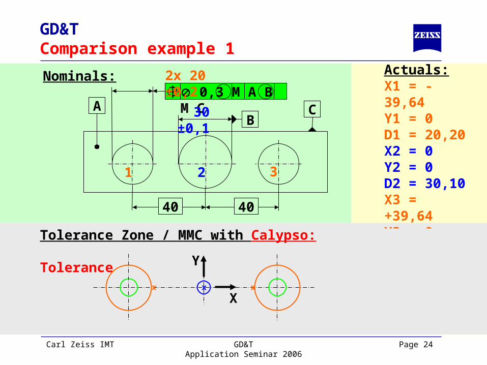
GD&TComparison example 1
Tolerance Zone / MMC with Calypso: Result:Out of Tolerance
Actual = 0,72 mm Exp. Tol.= 0,7 mm
Nominals: Actuals:X1 = -39,64Y1 = 0D1 = 20,20X2 = 0Y2 = 0D2 = 30,10X3 = +39,64Y3 = 0D3 = 20,20
B
40 40
30 ±0,1 CA
1 2 3
2x 20 ±0,2
x xx
X
Y

Carl Zeiss IMT GD&TApplication Seminar 2006
Page 25
0,3 M A B M C
GD&TComparison example 1
Nominals: Actuals:X1 = -39,64Y1 = 0D1 = 20,20X2 = 0Y2 = 0D2 = 30,10X3 = +39,64Y3 = 0D3 = 20,20
B
40 40
30 ±0,1 CA
1 2 3
2x 20 ±0,2
x xx
X
Y
Tolerance Zone / MMC with Calypso: Result:Out of Tolerance
Actual = 0,72 mm Exp. Tol.= 0,70 mm

Carl Zeiss IMT GD&TApplication Seminar 2006
Page 26
GD&TComparison example 1
Result with Traditional: In Tolerance
Actual = 0,72 mm Exp. Tol.= 0,9 mm
Nominals: Actuals:X1 = -39,64Y1 = 0D1 = 20,20X2 = 0Y2 = 0D2 = 30,10X3 = +39,64Y3 = 0D3 = 20,20
B
40 40
30 ±0,1 CA
1 2 3
x xx
0,3 M A B M C 2x 20 ±0,2

Carl Zeiss IMT GD&TApplication Seminar 2006
Page 27
GD&TComparison example 1
Nominals: Actuals:X1 = -39,64Y1 = 0D1 = 20,20X2 = 0Y2 = 0D2 = 30,10X3 = +39,64Y3 = 0D3 = 20,20
B
40 40
30 ±0,1 CA
1 2 3
0,3 M A B M C 2x 20 ±0,2
x xx
X
Y
Tolerance Zone / MMC with Traditional S/W: Result:In Tolerance
Actual = 0,72 mm Exp. Tol.= 0,90 mm

Carl Zeiss IMT GD&TApplication Seminar 2006
Page 28
GD&TComparison example 1
Nominals: Actuals:X1 = -39,64Y1 = 0D1 = 20,20X2 = 0Y2 = 0D2 = 30,10X3 = +39,64Y3 = 0D3 = 20,20
B
40 40
30 ±0,1 CA
1 2 3
0,3 M A B M C 2x 20 ±0,2
Tolerance Zone / MMC with Traditional S/W: Result:In Tolerance
Actual = 0,72 mm Exp. Tol.= 0,90 mmx xx
X
Y

Carl Zeiss IMT GD&TApplication Seminar 2006
Page 29
0,3 M A B M C
GD&TComparison example 2
Nominals: Actuals:X1 = -40,00Y1 = 0,45D1 = 20,20X2 = 0Y2 = 0D2 = 30,10X3 = +40,00Y3 = 0,45D3 = 20,20
B
40 40
30 ±0,1 CA
1 2 3
2x 20 ±0,2
x x
x X
Y
Tolerance Zone / MMC with Calypso: Result:In Tolerance
Actual = 0,70 mm Exp. Tol.= 0,70 mm

Carl Zeiss IMT GD&TApplication Seminar 2006
Page 30
0,3 M A B M C
GD&TComparison example 2
Nominals: Actuals:X1 = -40,00Y1 = 0,45D1 = 20,20X2 = 0Y2 = 0D2 = 30,10X3 = +40,00Y3 = 0,45D3 = 20,20
B
40 40
30 ±0,1 CA
1 2 3
2x 20 ±0,2
x x
x X
Y
Tolerance Zone / MMC with Calypso: Result:In Tolerance
Actual = 0,70 mm Exp. Tol.= 0,70 mm

Carl Zeiss IMT GD&TApplication Seminar 2006
Page 31
GD&TComparison example 2
Nominals: Actuals:X1 = -40,00Y1 = 0,45D1 = 20,20X2 = 0Y2 = 0D2 = 30,10X3 = +40,00Y3 = 0,45D3 = 20,20
B
40 40
30 ±0,1 CA
1 2 3
0,3 M A B M C 2x 20 ±0,2
x
x
X
Y x

Carl Zeiss IMT GD&TApplication Seminar 2006
Page 32
GD&TComparison example 2
Nominals: Actuals:X1 = -40,00Y1 = 0,45D1 = 20,20X2 = 0Y2 = 0D2 = 30,10X3 = +40,00Y3 = 0,45D3 = 20,20
B
40 40
30 ±0,1 CA
1 2 3
0,3 M A B M C 2x 20 ±0,2
Tolerance Zone / MMC with Traditional: Result:In Tolerance
Actual = 0,90 mm Exp. Tol.= 0,90 mm
x
x
X
Y x
Sometimes the conclusion from
either method is identical
....despite different
actuals and different
expanded tolerances!
Sometimes the conclusion from
either method is identical
....despite different
actuals and different
expanded tolerances!