ge fanuc automation - kraft power · cimplicity 90–ads genius modelmaster series three vumaster...
TRANSCRIPT
Î
GE Fanuc Automation
State Logic Products
State Logic� Processor
For Series 90�-30 PLC
User’s Guide
GFK-0726B March 1998
GFL–002
Warnings, Cautions, and Notesas Used in this Publication
Warning
Warning notices are used in this publication to emphasize that hazardous voltages,currents, temperatures, or other conditions that could cause personal injury exist in thisequipment or may be associated with its use.
In situations where inattention could cause either personal injury or damage toequipment, a Warning notice is used.
Caution
Caution notices are used where equipment might be damaged if care is not taken.
Note
Notes merely call attention to information that is especially significant to understandingand operating the equipment.
This document is based on information available at the time of its publication. Whileefforts have been made to be accurate, the information contained herein does notpurport to cover all details or variations in hardware or software, nor to provide forevery possible contingency in connection with installation, operation, or maintenance.Features may be described herein which are not present in all hardware and softwaresystems. GE Fanuc Automation assumes no obligation of notice to holders of thisdocument with respect to changes subsequently made.
GE Fanuc Automation makes no representation or warranty, expressed, implied, orstatutory with respect to, and assumes no responsibility for the accuracy, completeness,sufficiency, or usefulness of the information contained herein. No warranties ofmerchantability or fitness for purpose shall apply.
The following are trademarks of GE Fanuc Automation North America, Inc.
Alarm Master CIMSTAR Helpmate PROMACRO Series SixCIMPLICITY GEnet Logicmaster Series One Series 90CIMPLICITY 90–ADS Genius Modelmaster Series Three VuMasterCIMPLICITY PowerTRAC Genius PowerTRAC ProLoop Series Five Workmaster
Copyright 1992-1998 GE Fanuc Automation North America, Inc.All Rights Reserved
GE Fanuc Automation North America, Inc. GFJ–317C
Software License Agreement
YOU SHOULD CAREFULLY READ THE FOLLOWING TERMS AND CONDITIONS BEFORE OPENING THIS PACKAGE. OPENING THIS PACKAGE SIGNI-FIES YOUR ACCEPTANCE OF THESE TERMS AND CONDITIONS. IF YOU DO NOT AGREE WITH THEM, YOU SHOULD PROMPTLY RETURN THE PACK-AGE UNOPENED ALONG WITH ANY OTHER ITEM THAT WAS INCLUDED IN THE SAME CATALOG NUMBER FOR FULL CREDIT.
You, as the Customer, agree as follows:1. DEFINITIONS
”Application Software” shall mean those portions of the Licensed Software, in object code form only,created by GE Fanuc.
”Designated Computer” shall mean the one (1) computer upon which Customer shall run the Li-censed Software.
”Licensed Software” shall mean the Application Software plus any other software, in object codeform only, supplied by GE Fanuc pursuant to this Agreement. The Licensed Software may includethird party software, including but not limited to operating systems, licensed to GE Fanuc. If no oper-ating system software is included in the software provided under this Agreement, you must makeprovision for any required operating system software licenses.2. LICENSE
2.1 Except as provided in section 2.2 below, you are granted only a personal, non–transfer-able, nonexclusive license to use the Licensed Software only on the Designated Computer. You maycopy the Licensed Software into machine readable form for backup purposes in support of your useof the Licensed Software on the Designated Computer, limited to one copy. No other copies shall bemade unless authorized in writing by GE Fanuc. You may not reverse compile or disassemble thesoftware. The Licensed Software, comprising proprietary trade secret information of GE Fanuc and/or its licensors, shall be held in confidence by Customer and protected from disclosure to third par-ties. No title to the intellectual property is transferred. You must reproduce and include all applicablecopyright notices on any copy.
2.2 If you are an authorized GE Fanuc distributor or an Original Equipment Manufacturer whoincorporates the Licensed Software into your equipment for sale to an end user, you may transfer theLicensed Software to an end user provided that the end user agrees to be bound by the provisions ofthis Agreement.
2.3 GE Fanuc’s licensors having a proprietary interest in the Licensed Software shall have theright to enforce such interests, including the right to terminate this Agreement in the event of a breachof its terms pertaining to such proprietary interests.
2.4 EXCEPT AS PROVIDED IN SECTION 2.2 ABOVE, IF YOU TRANSFER POSSESSION OF ANYCOPY OF THE LICENSED SOFTWARE TO ANOTHER PARTY WITHOUT WRITTEN CONSENT OF GEFANUC, YOUR LICENSE IS AUTOMATICALLY TERMINATED. Any attempt otherwise to sublicense,assign or transfer any of the right, duties or obligations hereunder is void.
2.5 If the Licensed Software is being acquired on behalf of the U.S. Government, Departmentof Defense, the Licensed Software is subject to ”Restricted Rights”, including the legend to be affixedto the software as set forth in DOD Supplement to the Federal Acquisition Regulations (DFAR’s) para-graph 252.227–7013(c)(1). If software is being acquired on behalf of any other U.S. Governmententity, unit or agency, the Government’s rights shall be as defined in paragraph 52.227–19(c)(2) ofthe Federal Acquisition Regulations (FAR’s).3. WARRANTY
3.1 GE Fanuc warrants that the Application Software will be in substantial conformance withthe specifications in the manual pertaining thereto as of the date of shipment by GE Fanuc. If, withinninety (90) days of date of shipment, it is shown that the Application Software does not meet thiswarranty, GE Fanuc will, at its option, either correct the defect or error in the Application Software, freeof charge, or make available to Customer satisfactory substitute software, or, as a last resort, return toCustomer all payments made as license fees and terminate the license with respect to the ApplicationSoftware affected. GE Fanuc does not warrant that operation of the Application Software will be unin-terrupted or error free or that it will meet Customer’s needs. All other portions of the Licensed Soft-ware are provided ”as is” without warranty of any kind.
3.2 WITH RESPECT TO THE SOFTWARE WHICH IS THE SUBJECT OF THIS AGREEMENT, THEFOREGOING WARRANTIES ARE EXCLUSIVE AND ARE IN LIEU OF ALL OTHER WARRANTIESWHETHER WRITTEN, ORAL, IMPLIED OR STATUTORY. NO IMPLIED OR STATUTORY WARRANTY OFMERCHANTABILITY OR FITNESS FOR A PARTICULAR PURPOSE SHALL APPLY.4. LIMITATION OF LIABILITY
4.1 IN NO EVENT, WHETHER AS A RESULT OF BREACH OF CONTRACT, BREACH OF WAR-RANTY, TORT (INCLUDING NEGLIGENCE) OR OTHERWISE SHALL GE FANUC OR ITS SUPPLIERS BELIABLE FOR ANY SPECIAL, CONSEQUENTIAL, INCIDENTAL OR PENAL DAMAGES INCLUDING, BUTNOT LIMITED TO, LOSS OF PROFIT OR REVENUES, LOSS OF USE OF THE LICENSED SOFTWARE ORANY PART THEREOF, OR ANY ASSOCIATED EQUIPMENT, DAMAGE TO ASSOCIATED EQUIPMENT,COST OF CAPITAL, COST OF SUBSTITUTE PRODUCTS, FACILITIES, SERVICES OR REPLACEMENTPOWER, DOWN TIME COSTS, OR CLAIMS OF CUSTOMER’S CUSTOMERS AND TRANSFEREES FORSUCH DAMAGES EVEN IF GE FANUC HAS BEEN ADVISED OF THE POSSIBILITY OF SUCH DAMAGES.
4.2 EXCEPT AS PROVIDED IN SECTION 5, INDEMNITY, IN NO EVENT, WHETHER AS A RESULTOF BREACH OF CONTRACT OR WARRANTY, TORT (INCLUDING NEGLIGENCE) OR OTHERWISE,SHALL GE FANUC’S LIABILITY TO CUSTOMER FOR ANY LOSS OR DAMAGE ARISING OUT OF, ORRESULTING FROM THIS AGREEMENT, OR FROM ITS PERFORMANCE OR BREACH, OR FROM THELICENSED SOFTWARE OR ANY PART THEREFORE, OR FROM ANY SERVICE FURNISHED HERE-UNDER, EXCEED THE QUOTED CHARGES FOR THE LICENSED SOFTWARE. ANY SUCH LIABILITYSHALL TERMINATE UPON THE TERMINATION OF THE WARRANTY PERIOD AS SET FORTH IN SEC-TION 4.
4.3 If GE Fanuc furnishes Customer with advice or other assistance which concerns LicensedSoftware or any portion thereof supplied hereunder or any system or equipment on which any suchsoftware may be installed and which is not required pursuant to this Agreement, the furnishing of suchadvice or assistance will not subject GE Fanuc to any liability, whether in contract, warranty, tort, (in-cluding negligence) or otherwise.
4.4 The products to be licensed or sold hereunder are not intended for use in any nuclear,chemical or weapons production facility or activity, or other activity where failure of the productscould lead directly to death, personal injury or severe physical or environmental damage. If so used,GE Fanuc disclaims all liability for any damages arising as a result of the hazardous nature of the busi-ness in question, including but not limited to nuclear, chemical or environmental damage, injury orcontamination, and Customer shall indemnify, hold harmless and defend GE Fanuc, its officers, direc-tors, employees and agents against all such liability, whether based on contract, warranty, tort (in-cluding negligence), or any other legal theory, regardless of whether GE Fanuc had knowledge of thepossibility of such damages.5. INDEMNITY
5.1 GE Fanuc warrants that the Application Software shall be delivered free of any rightfulclaim for infringement of any United States patent or copyright. If notified promptly in writing and givenauthority, information and assistance, GE Fanuc shall defend, or may settle, at its expense, any suit orproceeding against Customer so far as based on a claimed infringement which would result in abreach of this warranty and GE Fanuc shall pay all damages and costs awarded therein against Cus-tomer due to such breach. In case the Application Software is in such suit held to constitute such aninfringement and its use is enjoined, GE Fanuc shall, at its expense and option, either procure for Cus-tomer the right to continued use, or replace same with a non–infringing product or part, or modify theApplication Software so that it becomes non–infringing, or remove the software and refund the li-cense charge pertaining thereto (less reasonable depreciation for any period of use) and any trans-portation costs separately paid by Customer. The foregoing states the entire liability of GE Fanuc forpatent and copyright infringement by the Licensed Software or any part thereof.
5.2 The indemnity under the preceding paragraph shall not apply to any use of ApplicationSoftware in conjunction with any other product in a combination not furnished by GE Fanuc as a partof this transaction. As to any such use in such combination, GE Fanuc assumes no liability whatsoev-er for patent and copyright infringement and Customer will hold GE Fanuc harmless against any in-fringement claims arising therefrom.6. TERM AND TERMINATION
6.1 You may terminate the license granted hereunder at any time by destroying the LicensedSoftware together with all copies thereof and notifying GE Fanuc in writing that all use of the LicensedSoftware has ceased and that same has been destroyed.
6.2 GE Fanuc, upon thirty (30) days notice, may terminate this Agreement or any license here-under if Customer fails to perform any obligation or undertaking to be performed by it under thisAgreement or if Customer attempts to assign this Agreement without the prior written consent of GEFanuc. Within twenty (20) days after any such termination of this Agreement, Customer shall certifyin writing to GE Fanuc that all use of the Licensed Software has ceased, and that same has been re-turned or destroyed, in accordance with GE Fanuc’s instructions.
6.3 Sections 4, 6 and 7 of this Agreement shall survive any expiration or termination andremain in effect. Termination of this Agreement or any license hereunder shall not relieve Customer ofits obligation to pay any and all outstanding charges hereunder nor entitle Customer to any refund ofsuch charges previously paid.7. EXPORT
7.1 If you intend to export (or reexport), directly or indirectly, the software products or techni-cal information relating thereto supplied hereunder or any portion thereof, it is your responsibility toassure compliance with U.S. export control regulations and, if appropriate, to secure any requiredexport licenses in your own name.8. GENERAL
8.1 This Agreement shall be governed by the laws of the State of Virginia, without regard to itsconflict of law provisions. The provisions of the United Nations Convention on the International Sale ofGoods shall not apply to this Agreement.
Should you have any questions concerning this Agreement, you may contact GE Fanuc by writiing to:GE Fanuc, P.O. Box 8106, Charlottesville, VA 22906.
YOU ACKNOWLEDGE THAT YOU HAVE READ THIS AGREEMENT, UNDERSTAND IT AND AGREE TOBE BOUND BY ITS TERMS AND CONDITIONS. YOU FURTHER AGREE THAT IT IS THE COMPLETEAND EXCLUSIVE STATEMENT OF THE AGREEMENT BETWEEN US AND SUPERSEDES ANY PRO-POSAL OR PRIOR AGREEMENT, ORAL OR WRITTEN, AND ANY OTHER COMMUNICATIONS BE-TWEEN US RELATING TO THE SUBJECT MATTER OF THIS AGREEMENT. FURTHER, NO CHANGE ORAMENDMENT TO THIS AGREEMENT SHALL BE EFFECTIVE UNLESS AGREED TO BY WRITTENINSTRUMENT SIGNED BY A DULY AUTHORIZED REPRESENTATIVE OF GE FANUC.

iii GFK-0726B
Preface
Content of this ManualChapter 1. State Logic� Processor Description
Chapter 2. Installation and Maintenance
Chapter 3. Troubleshooting
Chapter 4. Serial Communications
Chapter 5. Specifications
We Welcome Your Comments and SuggestionsAt GE Fanuc automation, we strive to produce quality technical documentation. Afteryou have used this manual, please take a few moments to complete and return theReader ’s Comment Card located on the next page.
� State Logic is a registered trademark of Adatek, Inc.
Contents
vii
GFK-0726B State Logic Processor for Series 90–30 PLC User’s Guide – March 1998
Chapter 1 State Logic Processor Description 1-1 . . . . . . . . . . . . . . . . . . . . . . . . . . . .
Physical Description 1-2 . . . . . . . . . . . . . . . . . . . . . . . . . . . . . . . . . . . . . . . . . . . . . .
Operational Description 1-4 . . . . . . . . . . . . . . . . . . . . . . . . . . . . . . . . . . . . . . . . . . .
Chapter 2 Installation and Maintenance 2-1 . . . . . . . . . . . . . . . . . . . . . . . . . . . . . . . .
Selecting the Right Slot 2-1 . . . . . . . . . . . . . . . . . . . . . . . . . . . . . . . . . . . . . . . . . . . .
Inserting the SLP 2-1 . . . . . . . . . . . . . . . . . . . . . . . . . . . . . . . . . . . . . . . . . . . . . . . . .
Configuration 2-2 . . . . . . . . . . . . . . . . . . . . . . . . . . . . . . . . . . . . . . . . . . . . . . . . . . . .
Battery 2-3 . . . . . . . . . . . . . . . . . . . . . . . . . . . . . . . . . . . . . . . . . . . . . . . . . . . . . . . . . .
Chapter 3 Troubleshooting 3-1 . . . . . . . . . . . . . . . . . . . . . . . . . . . . . . . . . . . . . . . . . . .
Status LED is not ON Steady 3-1 . . . . . . . . . . . . . . . . . . . . . . . . . . . . . . . . . . . . . . .
Serial Communication Problems 3-1 . . . . . . . . . . . . . . . . . . . . . . . . . . . . . . . . . . . .
Chapter 4 Serial Communications 4-1 . . . . . . . . . . . . . . . . . . . . . . . . . . . . . . . . . . . . .
Programming Serial Communications 4-2 . . . . . . . . . . . . . . . . . . . . . . . . . . . . . . .
Serial Port Setup 4-3 . . . . . . . . . . . . . . . . . . . . . . . . . . . . . . . . . . . . . . . . . . . . . . . . . .
Serial Cable 4-5 . . . . . . . . . . . . . . . . . . . . . . . . . . . . . . . . . . . . . . . . . . . . . . . . . . . . . .
Chapter 5 Specifications 5-1 . . . . . . . . . . . . . . . . . . . . . . . . . . . . . . . . . . . . . . . . . . . . .
Content of this Manual iii . . . . . . . . . . . . . . . . . . . . . . . . . . . . . . . . . . . . . . . . . . . .
We Welcome Your Comments and Suggestions v . . . . . . . . . . . . . . . . . . . . . . .

Contents
viii
GFK-0726B State Logic Processor for Series 90–30 PLC User’s Guide – March 1998
�!�+(� �,�� ���!% ��(!�) ��,�� � �))!) �,�� � � � � � � � � � � � � � � � � � � � � � � � � � � � � � � �
�!�+(� �,�� ��(!�) ��,�� �*�*� �&�!� �(&��))&( �,�� � � � � � � � � � � � � � � � � � � � � � � � � �
�!�+(� �,�� ��$'#��&�!�$�)*�(�&%�!�+(�*!&%��(��% �,�� � � � � � � � � � � � � � � � � � �
�!�+(� �,�� ���,��, � *& ��� ���#� �,� � � � � � � � � � � � � � � � � � � � � � � � � � � � � � � � �
�!�+(� �,�� �&("$�)*�( �� &( ���� *& ��� ���#� �,� � � � � � � � � � � � � � � � � � � � � � � �
�!�+(� �,�� ��(!�#�&(* ))!�%$�%*) �&( ��(!�) ��,�� ��� �,� � � � � � � � � � � � � � � � �
�!�+(� �,�� ������#� �&%%��*!&%) �&( ��(!�) ��,�� ��� �,�� � � � � � � � � � � � � � � �
Contents
ix
GFK-0726B State Logic Processor for Series 90–30 PLC User’s Guide – March 1998
����� �"�� ���������� ���������� �"�� � � � � � � � � � � � � � � � � � � � � � � � � � � � � � � � � � � � �
����� �"�� ��� �� ����� ��� �������� �"�� � � � � � � � � � � � � � � � � � � � � � � � � � � � � � � �
����� �"�� ����!����������������� �"�� � � � � � � � � � � � � � � � � � � � � � � � � � � � � � � � � � � �
����� �"�� ��������� �"�� � � � � � � � � � � � � � � � � � � � � � � � � � � � � � � � � � � � � � � � � � � � � � � �
����� �"�� ���!����������������� �"�� � � � � � � � � � � � � � � � � � � � � � � � � � � � � � � � � � � �
1
restart lowapp ARestart oddapp: ARestarts for autonumbers that do not restart ineach chapter. figure bi level 1, reset table_big level 1, reset chap_big level 1, reset1Lowapp Alwbox restart evenap:A1app_big level 1, resetA figure_ap level 1, resettable_ap level 1, reset figure level 1, reset table level 1, reset these restartsoddbox reset: 1evenbox reset: 1must be in the header frame of chapter 1. a:ebx, l 1resetA a:obx:l 1, resetA a:bigbx level 1 resetA a:ftr level 1 resetA c:ebx, l 1 reset1c:obx:l 1, reset1 c:bigbx level 1 reset1 c:ftr level 1 reset1 Reminders forautonumbers that need to be restarted manually (first instance will always be 4)let_in level 1: A. B. C. letter level 1:A.B.C. num level 1: 1. 2. 3. num_in level 1: 1. 2.3. rom_in level 1: I. II. III. roman level 1: I. II. III. steps level 1: 1. 2. 3.
1-1GFK-0726B
Chapter 1 State Logic Processor Description
The State Logic Processor (SLP) is a module which inserts into a Series 90�-30 PLC chas-sis. This module has the State Engine operating system to execute State Logic controlprograms produced by the ECLiPS programming software package.
The SLP exists together with a CPU module in the Series 90 -30 PLCs. The CPU must bea model 331, Revision 3.03 or higher. The CPU may execute a Relay Ladder Logic Pro-gram at the same time the State Logic Processor is executing a State Logic Program. TheSLP manipulates the CPU memory space and the CPU controls the I/O during its normalcycle of operations. More than one SLP can be installed in one Series 90-30 PLC system,although the SLP must be installed in the main rack with the CPU.
The software products, ECLiPS and OnTOP, are the user interfaces to the SLP. ECLiPS isa program development and on-line monitoring software product which runs on anIBM-PC compatible computer. OnTOP, the On-Line Troubleshooting Operator Pro-gram, also runs on an IBM-PC compatible computer. For questions about programmingor on-line functions, see the ECLiPS or OnTOP User’s Manuals.
IBM-PC is a registered trademark of International Business Machines Corporation.
1
1-2 State Logic Processor for Series 90–30 PLC User’s Guide – March 1998 GFK-0726B-
Physical Description
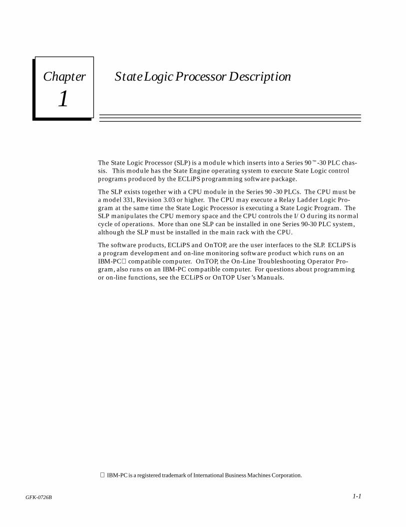
The SLP occupies a single slot in the Series 90-30 rack, communicating with the PLC CPUover the backplane to perform its many control functions. The SLP controls and accessesCPU I/O, register, and system data.
a45085
Î
ÎÎÎÎÎÎÎÎÎÎÎÎÎÎÎÎÎÎ
ÎÎÎÎÎÎ
ÎÎÎÎÎÎÎÎÎÎÎÎ
ÎÎÎÎÎÎ
ÎÎÎÎÎÎÎÎÎÎÎÎ
ÎÎÎÎÎÎÎÎÎÎÎÎ
ÎÎÎÎÎÎÎÎÎÎÎÎ
ÎÎÎÎÎÎ
ÎÎÎÎÎÎÎÎÎÎÎÎ
ÎÎÎÎÎÎÎÎÎÎÎÎ
LOCAL RACK CONFIGURATION
PS
CPU
SLP
Figure 1-1. SLP in Series 90-30 Chassis
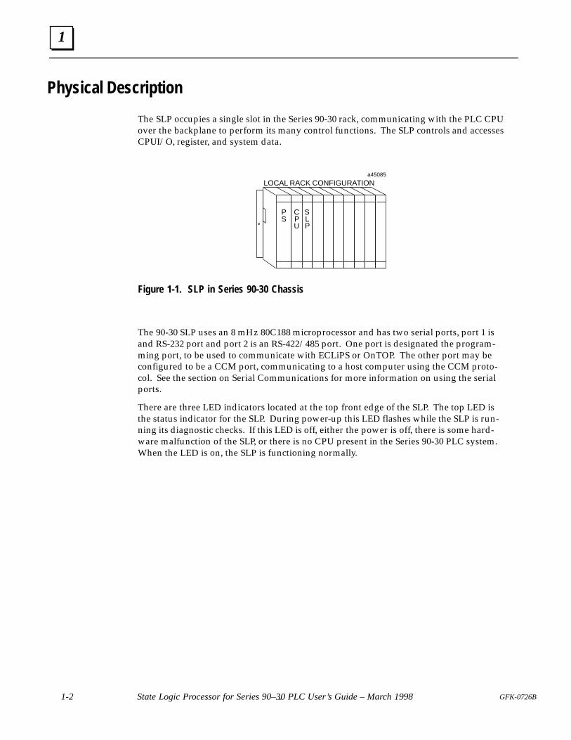
The 90-30 SLP uses an 8 mHz 80C188 microprocessor and has two serial ports, port 1 isand RS-232 port and port 2 is an RS-422/485 port. One port is designated the program-ming port, to be used to communicate with ECLiPS or OnTOP. The other port may beconfigured to be a CCM port, communicating to a host computer using the CCM proto-col. See the section on Serial Communications for more information on using the serialports.
There are three LED indicators located at the top front edge of the SLP. The top LED isthe status indicator for the SLP. During power-up this LED flashes while the SLP is run-ning its diagnostic checks. If this LED is off, either the power is off, there is some hard-ware malfunction of the SLP, or there is no CPU present in the Series 90-30 PLC system.When the LED is on, the SLP is functioning normally.
1
1-3GFK-0726B Chapter 1 State Logic Processor Description
a45127
OK
ÎÎÎÎÎÎ
ÎÎÎ
BDOK
RESTART
ÎÎ
BATTERY
OPENREPLACEMENT
BATTERYCONNECTOR
PORTS1 AND 2
SLP 300
CURRENTLYINSTALLEDBATTERY
CONNECTOR
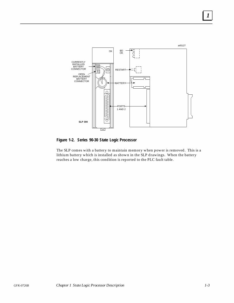
Figure 1-2. Series 90-30 State Logic Processor
The SLP comes with a battery to maintain memory when power is removed. This is alithium battery which is installed as shown in the SLP drawings. When the batteryreaches a low charge, this condition is reported to the PLC fault table.
1
1-4 State Logic Processor for Series 90–30 PLC User’s Guide – March 1998 GFK-0726B-
Operational Description
The State Logic Processor (SLP) uses areas in the CPU memory for I/O references andRegister values. The SLP and the CPU communicate this information over the PLCbackplane.
When a Ladder Logic control program and a State Logic control program are running atthe same time, the State Logic and Ladder Logic programs should not be controlling thesame outputs. The SLP cannot control an output that is being controlled by the CPU,since the 90-30 CPU always takes precedence when both processors are controlling thesame outputs.
All of the outputs used in the State Logic program should be selected to be contiguous ifsystem response time is important. Outputs being non-contiguous causes the scan rateto increase significantly.
When changing outputs the SLP writes to a byte of I/O bits at a time, so that any the SLPactually controls eight ouputs at a time. Therefore, if some outputs of a byte are notnamed in the SLP program, ECLiPS issuses a warning that the other outputs in that byteare changed when the program executes.
2 section level 1 1figure bi level 1 table_big level 1
2-1GFK-0726B
Chapter 2 Installation and Maintenance
This chapter describes how to install the SLP into a Series 90-30 PLC rack. There is also asection describing maintenance considerations.
Selecting the Right Slot
The SLP can be installed in any unused slot in the CPU rack of the Series 90-30 PLC if thefollowing rules are followed:
1. Configuration created by Logicmaster must match the physical location of themodules. Configuration faults are logged in the PLC fault table.
2. For the 90-30 SLP all the slots between the SLP and CPU must be occupied. If anyslots between are empty the SLP cannot communicate with the CPU. The SLP mustbe in the main rack with the CPU.
Inserting the SLP
Follow these steps to insert the SLP into the Series 90-30 rack:
1. Power down the Series 90-30 PLC system
2. Locate the desired rack and slot.
3. Slide the 90-30 SLP completely into the slot.
4. Press down firmly to lock the module in place, but do not use excessive force.
5. Power up the PLC rack. The Status LED flashes during power-up diagnostics. TheLED comes on steady when the SLP is ready for operations.
2
2-2 State Logic Processor for Series 90-30 PLC User’s Guide – March 1998 GFK-0726B
Configuration
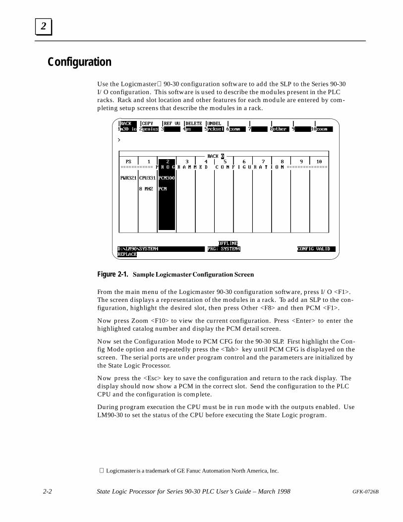
Use the Logicmaster 90-30 configuration software to add the SLP to the Series 90-30I/O configuration. This software is used to describe the modules present in the PLCracks. Rack and slot location and other features for each module are entered by com-pleting setup screens that describe the modules in a rack.
Figure 2-1. ����������������� ������ �����
From the main menu of the Logicmaster 90-30 configuration software, press I/O <F1>.The screen displays a representation of the modules in a rack. To add an SLP to the con-figuration, highlight the desired slot, then press Other <F8> and then PCM <F1>.
Now press Zoom <F10> to view the current configuration. Press <Enter> to enter thehighlighted catalog number and display the PCM detail screen.
Now set the Configuration Mode to PCM CFG for the 90-30 SLP. First highlight the Con-fig Mode option and repeatedly press the <Tab> key until PCM CFG is displayed on thescreen. The serial ports are under program control and the parameters are initialized bythe State Logic Processor.
Now press the <Esc> key to save the configuration and return to the rack display. Thedisplay should now show a PCM in the correct slot. Send the configuration to the PLCCPU and the configuration is complete.
During program execution the CPU must be in run mode with the outputs enabled. UseLM90-30 to set the status of the CPU before executing the State Logic program.
Logicmaster is a trademark of GE Fanuc Automation North America, Inc.
2
2-3GFK-0726B Chapter 2 Installation and Maintenance
Battery
The State Logic Processor comes with a 3 volt lithium battery (IC697ACC701) to maintainmemory through a power cycle. If the battery charge becomes low, a fault is set in thefault table. These faults can be monitored by the State Logic program.
To replace the battery, connect the new battery to the extra set of battery connectionsthen disconnect the old battery. A Product Safety Data Sheet for the battery is available.Order from GE Fanuc using number GFK-0633.
3 section level 1 1figure bi level 1 table_big level 1
3-1GFK-0726B
Chapter 3 Troubleshooting
This chapter provides procedures for diagnosing State Logic Processor (SLP) problems.If these procedures do not solve the problem, contact the GE Fanuc Hotline(1-800-828-5747) for assistance.
Status LED is not ON Steady
1. Check that power is supplied to the I/O rack housing the SLP. Try removing andreinstalling the SLP.
2. Cycle power to the SLP, then press the reset button for more than 5 seconds.
3. Turn the power OFF and disconnect the battery and short the SLP battery terminalconnection points to clear the SLP. Reconnect the battery, turn ON power again, andreset the SLP.
4. Check that the CPU is functioning properly by checking its “OK” LED.
5. Check that there are no empty slots between the CPU and the SLP. If there areempty slots, the Status LED blinks continuously.
6. If the Status LED is still not ON, try to download a program from ECLiPS or OnTOP.If you can connect with the SLP and download a program, then the Status LED isfaulty.
7. If you get a message that ECLiPS or OnTOP cannot connect to the controller, thencheck the fault table in the CPU using Logicmaster 90. If there is a fault “Bad ormissing module”, then the SLP is faulty and must be returned for repairs.
8. If there is no fault then contact the GE Fanuc Hotline for assistance.
Serial Communication Problems
This section is split into two parts, communication problems to ECLiPS or OnTOP andproblems with other serial devices.
3
3-2 State Logic Processor for Series 90-30 PLC User’s Guide – March 1998 GFK-0726B
Communications Problems with ECLiPS or OnTOP1. Check that the serial cable used conforms to one of the types specified for
communications to the SLP ports. Check that the cable is firmly secured at bothends.
2. When there is a communications problem, a message indicating problemsconnecting to the controller is displayed together with some options. Select the“Change Host Comm Port Settings” option to check the computer port being usedand the baud rate. The default SLP baud rate is 19.2K.
3. The SLP programming port may have been changed. ECLiPS and OnTOP must beconnected to the designated programming port. The default programming port isPort 1 but can be changed by ECLiPS or OnTOP. Make sure the serial cable isconnected to the current programming port.
4. The SLP serial port configuration may have been changed. These parameters canonly be changed by Statements using the Set_Commport keyword in the State Logicprogram. Reset the SLP to return the SLP serial port parameters to their defaultstate. If the program is setup to start running automatically and the programcontinues to change the serial port parameters after the reset switch is pressed, turnoff the power to the SLP, remove the battery, and short the SLP battery leads to resetthe SLP.
5. Port 2 of the 90-30 SLP is an RS-422/485 port and Port 1 is an RS-232 port. Make surethat the host computer serial port setup matches the SLP port for RS-232-RS-422/485option.
6. If there is still no communication between the SLP and OnTOP or ECLiPS then callthe GE Fanuc Hotline for assistance.
Communications Problems with Another Serial Device1. Check that the serial cable used conforms to one of the types specified for
communications to the SLP ports. Check that the cable is firmly secured at bothends.
2. Make sure that the serial port parameters of the serial device match the settings ofthe SLP. The default settings of the SLP are 19.2K baud rate, 8 data bits, 2 stop bits,and no parity.
3. Make sure the RS-422/485-RS-232 standards are the same for SLP and the serialdevice
4. When connecting some device to the programming port, make sure that you exitECLiPS or OnTOP normally before disconnecting from the SLP.
5. If there are still problems contact the GE Fanuc Hotline for assistance.
4 section level 1 1figure bi level 1 table_big level 1
4-1GFK-0726B
Chapter 4 Serial Communications
Serial communications with the State Logic Processor (SLP) is provided through one ofthe two serial ports. Each of these ports can send and receive serial data independentfrom the other. Port 1 is an RS-232 port and port 2 is an RS-422/485 port. There is onlyone 25-pin connector on the SLP which provides access to the connections for bothports. The SLP comes with a WYE cable which provides one 25-pin connector for eachport.
ECLiPS and OnTOP must communicate with the SLP through the programming port.Either port can be the programming port, but port 1 is the default programming port.When ECLiPS or OnTOP is not connected to the SLP, the programming port can be usedto communicate with some other serial device. To properly set the programming port tocommunicate with another device, exit ECLiPS or OnTOP normally before disconnect-ing from the SLP.
Either of these ports may also be a CCM port. The CCM port uses the GE Fanuc CCM2protocol for all communications. This protocol is used for connecting the SLP with a hostcomputer which collects data and changes data in the SLP. Typical CCM uses are con-necting to a graphical user interface program such as CIMPLICITY� or for custom hostinteraction with the SLP.
The SLP is always a slave to the host, i.e., all communications are initiated by the hostcomputer. The SLP may be one of several devices on a CCM network. The CCM port isalways the port that is not designated as the programming port. The CCM port is a nor-mal RS-232 or RS-422/485 port when CCM communications are not enabled.
� CIMPLICITY is a registered trademark of GE Fanuc Automation North America, Inc.
4
4-2 State Logic Processor for Series 90-30 PLC User’s Guide – March 1998 GFK-0726B
Programming Serial Communications
The program communicates through two ports using WRITE and READ terms. For ex-ample:
State: Get_Setpoint
Write “Enter New Setpoint” to Operator_Panel.
Read SetPoint1 from Operator_Panel, then go to Check_Setpoint State.
The Write Term sends the string of characters, Enter New Setpoint, to the port defined asthe Operator_Panel. This same port is then monitored for input by the Read Term in thenext Statement. The variable Setpoint1 is set to the value entered through the specifiedport.
In this example the WRITE and READ term information is directed to a particular port.Operator_Panel in this case is defined in ECLiPS as Port 1 or Port 2. Use the ECLiPS, DE-FINE or LIST menus to make the port definitions. The default names are Port_1 andPort_2.
The Read and Write Terms may also be used without being directed to any particularchannel, for example:
State: Choose_Recipe
Write “Enter Recipe Number”.
Read Recipe_Number, then go to StartBatch State.
Since no port is specified in this example, information is sent to the programming port.For a more detailed discussion of programming serial input and output, refer to the Ref-erence Section of the ECLiPS User’s Manual.
4
4-3GFK-0726B Chapter 4 Serial Communications
Serial Port Setup
There are several serial port configuration options. Some of these options are set usingECLiPS or OnTOP, and others can only be set by an executing State Logic program.
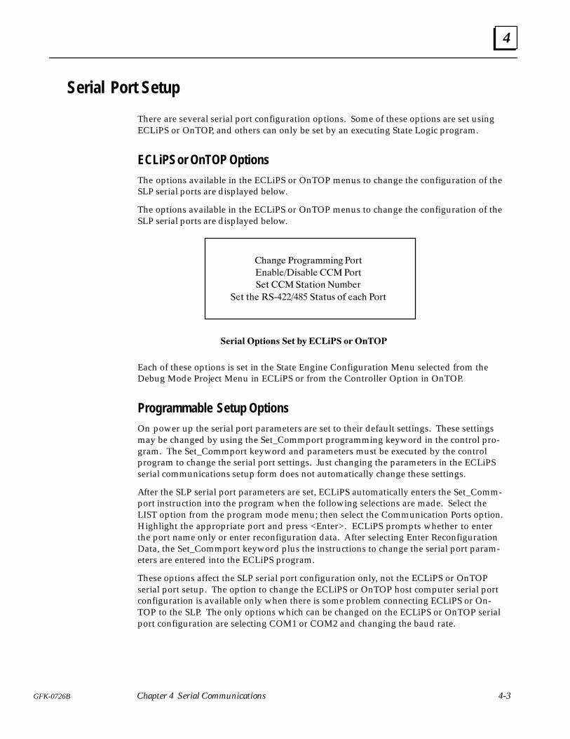
ECLiPS or OnTOP OptionsThe options available in the ECLiPS or OnTOP menus to change the configuration of theSLP serial ports are displayed below.
The options available in the ECLiPS or OnTOP menus to change the configuration of theSLP serial ports are displayed below.
������ ����������� ����
������������� ������
��� ��������� ������
��� ��� ��������� ������ �� ���� ����
���� ������� ��� � ������ �� �����
Each of these options is set in the State Engine Configuration Menu selected from theDebug Mode Project Menu in ECLiPS or from the Controller Option in OnTOP.
Programmable Setup OptionsOn power up the serial port parameters are set to their default settings. These settingsmay be changed by using the Set_Commport programming keyword in the control pro-gram. The Set_Commport keyword and parameters must be executed by the controlprogram to change the serial port settings. Just changing the parameters in the ECLiPSserial communications setup form does not automatically change these settings.
After the SLP serial port parameters are set, ECLiPS automatically enters the Set_Comm-port instruction into the program when the following selections are made. Select theLIST option from the program mode menu; then select the Communication Ports option.Highlight the appropriate port and press <Enter>. ECLiPS prompts whether to enterthe port name only or enter reconfiguration data. After selecting Enter ReconfigurationData, the Set_Commport keyword plus the instructions to change the serial port param-eters are entered into the ECLiPS program.
These options affect the SLP serial port configuration only, not the ECLiPS or OnTOPserial port setup. The option to change the ECLiPS or OnTOP host computer serial portconfiguration is available only when there is some problem connecting ECLiPS or On-TOP to the SLP. The only options which can be changed on the ECLiPS or OnTOP serialport configuration are selecting COM1 or COM2 and changing the baud rate.
4
4-4 State Logic Processor for Series 90-30 PLC User’s Guide – March 1998 GFK-0726B
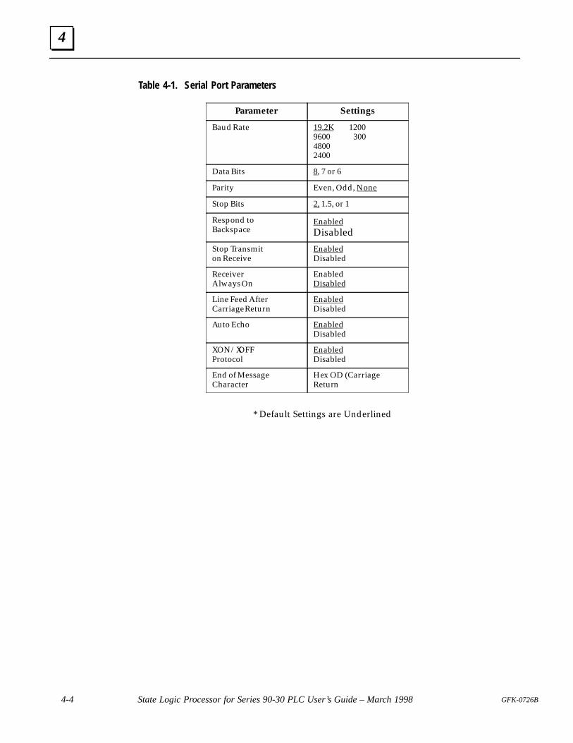
Table 4-1. Serial Port Parameters
Parameter Settings
Baud Rate 19.2K 12009600 30048002400
Data Bits 8, 7 or 6
Parity Even, Odd, None
Stop Bits 2, 1.5, or 1
Respond to Backspace
EnabledDisabled
Stop Transmiton Receive
EnabledDisabled
ReceiverAlways On
EnabledDisabled
Line Feed AfterCarriage Return
EnabledDisabled
Auto Echo EnabledDisabled
XON/XOFFProtocol
EnabledDisabled
End of MessageCharacter
Hex OD (CarriageReturn
* Default Settings are Underlined
4
4-5GFK-0726B Chapter 4 Serial Communications
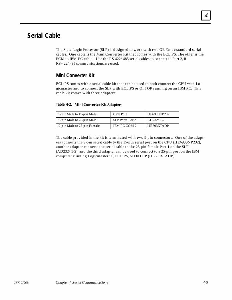
Serial Cable
The State Logic Processor (SLP) is designed to work with two GE Fanuc standard serialcables. One cable is the Mini Converter Kit that comes with the ECLiPS. The other is thePCM to IBM-PC cable. Use the RS-422/485 serial cables to connect to Port 2, ifRS-422/485 communications are used.
Mini Converter KitECLiPS comes with a serial cable kit that can be used to both connect the CPU with Lo-gicmaster and to connect the SLP with ECLiPS or OnTOP running on an IBM PC. Thiscable kit comes with three adapters:
Table 4-2. � ���� �� �� ������ �
9-pin Male to 15-pin Male CPU Port HE693SNP232
9-pin Male to 25-pin Male SLP Ports 1 or 2 AD232/1-2
9-pin Male to 25-pin Female IBM PC COM 2 HE 693XTADP
The cable provided in the kit is terminated with two 9-pin connectors. One of the adapt-ers connects the 9-pin serial cable to the 15-pin serial port on the CPU (HE693SNP232),another adapter connects the serial cable to the 25-pin female Port 1 on the SLP(AD232/1-2), and the third adapter can be used to connect to a 25-pin port on the IBMcomputer running Logicmaster 90, ECLiPS, or OnTOP (HE693XTADP).
4
4-6 State Logic Processor for Series 90-30 PLC User’s Guide – March 1998 GFK-0726B
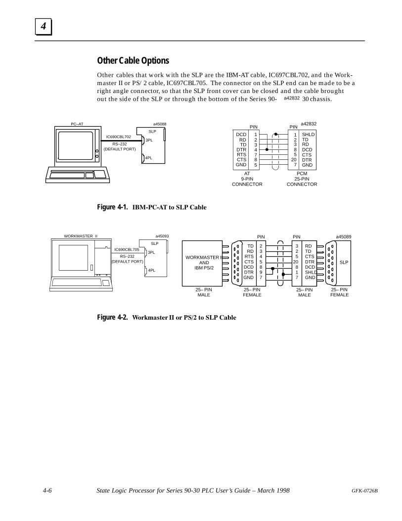
Other Cable OptionsOther cables that work with the SLP are the IBM-AT cable, IC697CBL702, and the Work-master II or PS/2 cable, IC697CBL705. The connector on the SLP end can be made to be aright angle connector, so that the SLP front cover can be closed and the cable broughtout the side of the SLP or through the bottom of the Series 90- a42832 30 chassis.
SLP
ÎÎÎÎÎÎÎÎÎÎÎÎÎÎ
a45088
ÎÎ3PL
4PL
PC–AT
RS–232(DEFAULT PORT)
IC690CBL702
PIN PINa42832
PCM25-PIN
CONNECTOR
AT9-PIN
CONNECTOR
SHLDTDRDDCDCTSDTRGND
12385
207
DCDRDTD
DTRRTSCTSGND
1234785
Figure 4-1. ������� �� �� �����
ÎÎÎÎÎÎÎÎÎÎÎÎÎÎÎÎ
ÎÎÎÎÎÎÎÎÎÎÎÎÎÎÎ
ÎÎÎÎÎÎÎÎÎÎÎÎÎÎÎÎ
a45093
ÎÎ3PL
4PL
WORKMASTER II
RS–232(DEFAULT PORT)
IC690CBL705
SLP
SLP
a45089
2345897
TDRD
RTSCTSDCDDTRGND
PIN PIN
25– PINFEMALE
25– PINMALE
WORKMASTER IIAND
IBM PS/2
25– PINFEMALE
RDTDCTSDTRDCDSHLDGND
325
20817
ÎÎÎ
ÎÎÎÎÎÎÎÎÎ
ÎÎÎ
ÎÎÎ
ÎÎÎ
ÎÎ
ÎÎÎÎÎÎÎ
ÎÎÎÎÎ
25– PINMALE
Figure 4-2. ��������� �� �� ��� �� �� �����
4
4-7GFK-0726B Chapter 4 Serial Communications
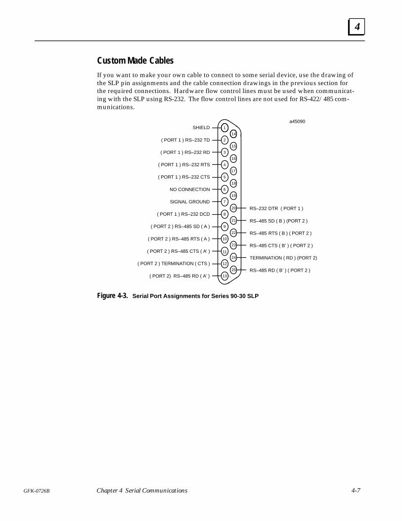
Custom Made CablesIf you want to make your own cable to connect to some serial device, use the drawing ofthe SLP pin assignments and the cable connection drawings in the previous section forthe required connections. Hardware flow control lines must be used when communicat-ing with the SLP using RS-232. The flow control lines are not used for RS-422/485 com-munications.
a45090ÎÎÎÎÎÎ
ÎÎÎÎÎÎÎÎÎÎÎÎ
ÎÎÎÎÎÎ
ÎÎÎÎÎÎÎÎÎ
2
1
3
4
5
6
7
8
9
10
11
12
13
15
16
17
18
19
20
21
22
23
24
25
14
ÎÎ
RS–232 DTR ( PORT 1 )
RS–485 SD ( B ) (PORT 2 )
RS–485 RTS ( B ) ( PORT 2 )
RS–485 CTS ( B’ ) ( PORT 2 )
TERMINATION ( RD ) (PORT 2)
RS–485 RD ( B’ ) ( PORT 2 )
SHIELD
( PORT 1 ) RS–232 TD
( PORT 1 ) RS–232 RD
( PORT 1 ) RS–232 RTS
( PORT 1 ) RS–232 CTS
NO CONNECTION
SIGNAL GROUND
( PORT 1 ) RS–232 DCD
( PORT 2 ) RS–485 SD ( A )
( PORT 2 ) RS–485 RTS ( A )
( PORT 2 ) RS–485 CTS ( A’ )
( PORT 2 ) TERMINATION ( CTS )
( PORT 2) RS–485 RD ( A’ )
Figure 4-3. Serial Port Assignments for Series 90-30 SLP
4
4-8 State Logic Processor for Series 90-30 PLC User’s Guide – March 1998 GFK-0726B
a45091
ÎÎÎÎÎÎÎÎÎ
ÎÎÎÎÎÎÎÎÎ
ÎÎÎÎÎÎÎÎÎ
ÎÎÎÎÎÎÎÎÎÎÎÎ
2
1
3
4
5
6
7
8
9
10
11
12
13
15
16
17
18
19
20
21
22
23
24
25
14
RS–232 DTR
SHIELD
RS–232 TD
RS–232 RD
RS–232 RTS
RS–232 CTS
SIGNAL GROUND
RS–232 DCD
ÎÎÎÎÎÎÎÎÎ
ÎÎÎÎÎÎÎÎÎ
ÎÎÎÎÎÎÎÎÎ
ÎÎÎÎÎÎÎÎÎÎÎÎ
2
1
3
4
5
6
7
8
9
10
11
12
13
15
16
17
18
19
20
21
22
23
24
25
14
ÎÎ
RS–485 SD ( B )
RS–485 RTS ( B )
RS–485 CTS ( B’ )
TERMINATION ( RD )
RS–485 RD ( B’ )
SHIELD
SIGNAL GROUND
RS–485 SD ( A )
RS–485 RTS ( A )
RS–485 CTS ( A’ )
TERMINATION ( CTS )
RS–485 RD ( A’ )
PORT 1 PORT 2
1 FOOT
ÎÎÎÎ
a44225
Î
PORT 1PORT 2
PCM COMM. CABLEIC693CBL305B
RS–23225–PIN FEMALE-
CONNECTORPIN 1
PIN 1RS–232/RS–48525–PIN FEMALECONNECTOR
LABELÎÎÎÎ
PIN 1 RS–23225–PIN MALECONNECTOR
(+2.0 INCH, –0 INCH)
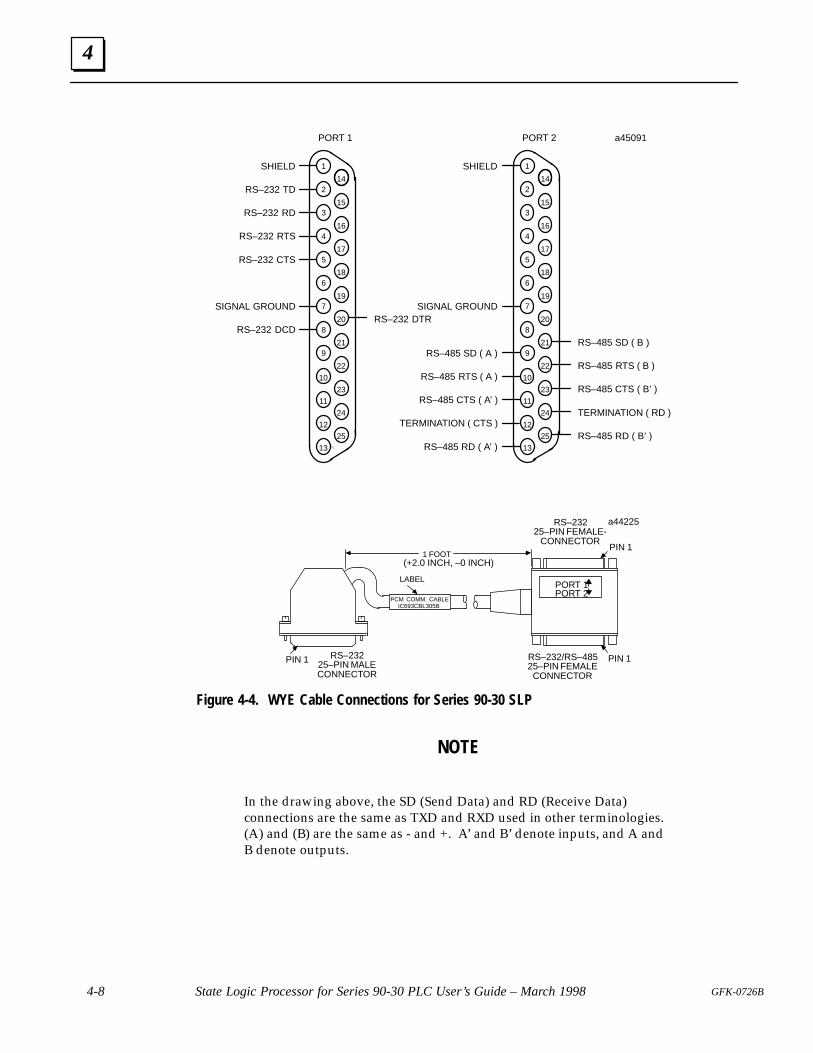
Figure 4-4. WYE Cable Connections for Series 90-30 SLP
NOTE
In the drawing above, the SD (Send Data) and RD (Receive Data)connections are the same as TXD and RXD used in other terminologies.(A) and (B) are the same as - and +. A’ and B’ denote inputs, and A andB denote outputs.
5 section level 1 1figure bi level 1 table_big level 1
5-1GFK-0726B
Chapter 5 Specifications
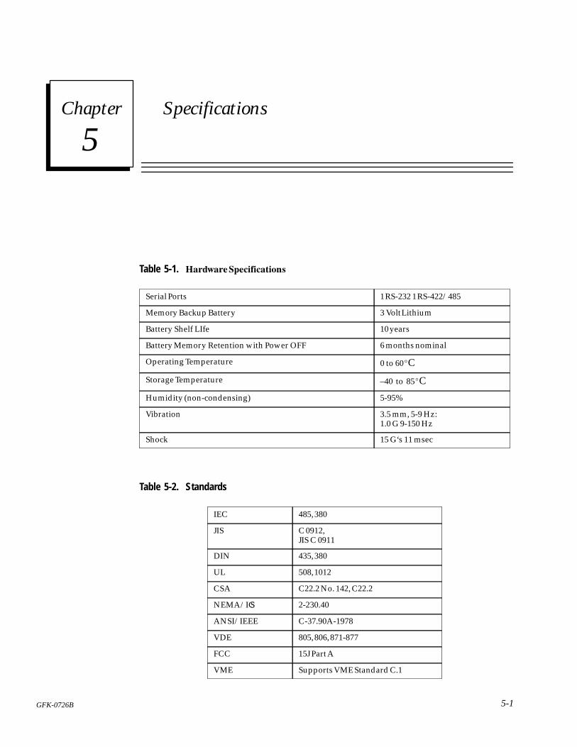
Table 5-1. �� ��� �����������
Serial Ports 1 RS-232 1 RS-422/485
Memory Backup Battery 3 Volt Lithium
Battery Shelf LIfe 10 years
Battery Memory Retention with Power OFF 6 months nominal
Operating Temperature 0 to 60�C
Storage Temperature –40 to 85�C
Humidity (non-condensing) 5-95%
Vibration 3.5 mm, 5-9 Hz:1.0 G 9-150 Hz
Shock 15 G‘s 11 msec
Table 5-2. Standards
IEC 485, 380
JIS C 0912,JIS C 0911
DIN 435, 380
UL 508, 1012
CSA C22.2 No. 142, C22.2
NEMA/ICS 2-230.40
ANSI/IEEE C-37.90A-1978
VDE 805, 806, 871-877
FCC 15J Part A
VME Supports VME Standard C.1
5
5-2 State Logic Processor for Series 90-30 PLC User’s Guide – March 1998 GFK-0726B
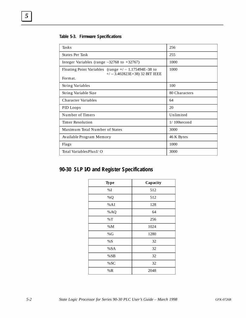
Table 5-3. Firmware Specifications
Tasks 256
States Per Task 255
Integer Variables (range –32768 to +32767) 1000
Floating Point Variables (range +/– 1.175494E–38 to +/– 3.402823E+38) 32 BIT IEEEFormat.
1000
String Variables 100
String Variable Size 80 Characters
Character Variables 64
PID Loops 20
Number of Timers Unlimited
Timer Resolution 1/100 second
Maximum Total Number of States 3000
Available Program Memory 46 K Bytes
Flags 1000
Total Variables Plus I/O 3000
90-30 SLP I/O and Register Specifications
Type Capacity
%I 512
%Q 512
%AI 128
%AQ 64
%T 256
%M 1024
%G 1280
%S 32
%SA 32
%SB 32
%SC 32
%R 2048