ge ham news - americanradiohistory.com€¦ · crystal filter practically inoperative unless a 455...
TRANSCRIPT
et~ TUBES
C -I HAM Niws .) MARCH -APRIL, 1957 VOL. 12-NO.2
PACKAGED SELECTIVITY
.® - ._
CONTENTS
455 -KC
MECHANICAL
FILTER
RECEIVER
ADAPTER
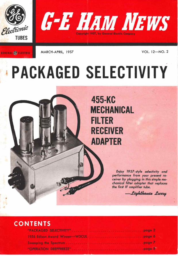
Enjoy 1957 -style selectivity and performance from your present re- ceiver by plugging in this simple me- chanical filter adapter that replaces the first IF amplifier tube.
-.& sonde Ja

PACKAGED SELECTIVITY GENERAL INFORMATION
There are clear channels on today's crowded amateur bands even though you may not find them easily with your present communications receiver. Try tuning one of the new high -selectivity amateur:receivers across a popu- lar band and several clear channels usually will be found.
It is now possible to add this new order of selectivity to your present receiver-which otherwise may be quite satisfactory-by constructing a simple mechanical filter adapter unit that is substituted for the first 455 -
kilocycle intermediate -frequency amplifier tube (or the IF tube) without making any under -chassis changes in the receiver. Simply connect the adapter to a power source, remove an IF amplifier tube, and insert two short coaxial cables into the tube socket, as shown in Fig. 1. These cables carry the IF signal to and from the adapter, which may then be tucked away in an un- occupied corner of your receiver cabinet. An adapter that plugs directly into the tube socket could be con- structed, but the available space is very restricted in many receivers.
The primary design and construction consideration of this adapter is to completely isolate the input and output circuits. Any stray coupling can cause signal leakage around the filter unit, thus impairing its effec- tiveness. For this reason, we recommend that the adapter be constructed as described.
Many modern medium-priced and older high-priced communications receivers now in general use are con- venient to operate, have good frequency stability and sensitivity, but lack the necessary "skirt" selectivity to sufficiently reject strong signals that are only a few kilocycles higher or lower in frequency from a desired signal. The shaded area of curve "A" in Fig. 2 shows the typical selectivity characteristic of several popular medium-priced communications receivers. Although the peak, or "nose" of this curve is usually only a few kilocycles wide, the "skirt" selectivity 60 decibels down from the peak may be from 15 to 30 kilocycles broad! Small wonder that strong local signals a few kilocycles up the band from a station you are trying to copy may sometimes paralyze your receiver!
Incidentally, the curves at "A" are the bandwidth figures for a receiver with the selectivity control set for the sharpest bandwidth that does not utilize the crystal filter, if the receiver has one. Switching in the crystal filter will greatly sharpen the "nose" of the selectivity curve, but the width of the "skirts" may not be materially reduced.
4.0 TO 5.5 KC
WIDE AT-6DB DOWN
INPUI CABIf
CS T GP,D Pm --I
LTJ , ;,I.:1,
FILTER ADAPTER - OUTPUT
CABLE
C6 PLATE PIA
PROUNDED \ .L ---- I2NDIr
L -_J Fig. 1. Diagram showing how the mechanical filter adapter is connected to the first IF tube socket in the receiver.
When the "PACKAGED SELECTIVITY" adapter is installed in a receiver of this type, the crystal filter can then be utilized to reject, or "notch out" any heterodyne -type interference that may fall within the bandpass of the mechanical filter. Or, a "Q" multiplier may be connected into the receiver for this purpose. The mechanical filter has none of the characteristic "ringing" sound that sometimes results when a crystal filter is adjusted to produce an extremely sharp selectiv- ity peak response curve. And lastly, the random noise output from the receiver will be reduced.
SELECTIVITY SYSTEMS There are two systems generally used to obtain a
bandpass characteristic that approaches the "ideal" communications receiver selectivity curve for voice - modulated signals, shown at "B" in Fig. 2. One system is the "packaged filter," including the mechanical filter as used in this adapter circuit, the crystal lattice filter, and certain toroidally-wound inductive filters. A good crystal lattice filter usually must be assembled from carefully matched war -surplus quartz crystals in this frequency range, while the toroidal filter operates at a lower frequency and requires a more complex frequency conversion adapter circuit.
The second method is to utilize a string of high "Q" circuits in the receiver's IF amplifier that are tuned to achieve the desired bandpass. This system can be space consuming, difficult to adjust and fairly expensive if quality components are employed.
Of the three packaged filters, the mechanical type has certain advantages. It is very compact, readily available in a variety of bandwidths, has an excellent selectivity curve, and is roughly equivalent in cost to the other systems having comparable selectivity. Curve "C" in Fig. 2 illustrates the selectivity of the 3.1 -kilo -
--el 3 KCr-- '..I KC
-6 DB
AVERAGE E-\ DIVI TY - ism
SELECTIVITY - RANGE (WITHOUT
SDEESLEIRCECURVE
-24 DB CRYSTAL
1_II -42 DB
-60 DB
0 DB
--.{ 3KGl.11-6.5KC_.4
MECHANICAL FILTER 15 TO 30 KC WIDE AT -A SELECTIVITY CURVE
-60 DB DOWN
Fig. 2. Bandwidth curves showing: A-selectivity range of most medium-priced single -conversion receivers with crystal filter out of circuit; B-ideal selectivity curve for voice reception; and C-selectivity curve of a 455 -kilocycle mechanical filter with a 3.1 -kilocycle bandwidth.
2

)
TO GROUNDED v PIN
Fig. 3. Schematic diagram of the mechanical filter adapter.
cycle mechanical filter bandwidth suitable for AM and SSB reception. Compare this curve with "A," which is drawn to the same scale!
A mechanical filter is, as the name implies, a series of vibrating, mechanically resonant, disks tied together with small rods that transmit the vibrations from disk to disk. Small inductances coupled to the disks at both ends convert the electrical energy passing through them into mechanical vibrations at the input end and back into electrical energy at the output end. Each disk has a "Q" 20 times as high as an ordinary tuned circuit, so that several disks of slightly different resonant frequencies must be coupled together to achieve a nearly rectangular bandpass response curve.'
Since the filter characteristic determines the over- all intermediate frequency bandwidth, any other tuned circuits in the intermediate -frequency amplifier may utilize a low-cost, readily available coil, such as the vari-loopstick, instead of more expensive IF coupling transformers.
The adapter model pictured on the cover was as- sembled from parts that cost about five dollars (plus $45.00 for the Collins F -455J-31 filter). W2FZW, de- signer of the adapter, was so pleased with his station receiver's new-found selectivity (formerly about 30 kilocycles broad at the -60-db points) after testing the
' adapter that he promptly added "A4" to the receiver's model number!
Receivers with an intermediate -frequency amplifier on 465 kilocycles (mostly found in pre -World War II receivers) must be re -aligned to the 455 -kilocycle center frequency of the mechanical filter, otherwise very little signal will be heard when the adapter is added. This change in the intermediate frequency will render the crystal filter practically inoperative unless a 455 - kilocycle filter crystal is substituted for the original.
ELECTRICAL DETAILS The adapter picks up the signal from the control grid
of the receiver's first IF amplifier tube socket through coupling capacitor C,, then feeds it to the grid of a pentode tube, V,, in the adapter unit, as shown in the schematic diagram, Fig. 3. The plate circuit of Vi is capacity -coupled to the input terminals on the me- chanical filter to keep plate current from flowing through this coil. A much wider signal voltage range can be handled by the filter without distortion when no cur- rent flows through the coils. Both filter coils are tuned to resonance at the operating frequency by fixed capaci- tors C1 and C3.
'A comprehensive discussion of mechanical filters may be found in the following articles: QST magazine, "Mechanical Bandpass Filters for IF Ranges," February, 1953, page 22; Proceedings of the IRE, Jan- uary, 1957, page 5; and in Collins Application Bulletin No. 200.
PARTS LIST
CI, C4-600-mmf ceramic (270- and 330- mmf in parallel).
C2, C3-120-mmf ceramic.
C1-10-mmf tubular ceramic (Aerovox Type CI -1 or Erie Type 315).
FL4-455-kilocycle mechanical filter with 3.1 -kilocycle bandwidth and 9 -pin minia- ture plug-in base (Collins 455J-31).
1,, 1.2-200-uh iron slug -tuned coil (Gray- burne or Superex Vari-loopstick Model VI, or Miller No. 6300).
Pi-male octal plug with retaining ring (Amphenol 86 -PM -8).
V2-6BA6 or 6BJ6 tubes.
The filter output terminals are connected directly to the control grid of V1 and the chassis, since no grid current will flow in this stage. The output signal from V, is again capacity coupled back into the plate ter- minal of the receiver's IF tube socket. The tuned cir- cuits connected to the plates of both V, and V2 are composed of vari-loopstick coils, L, and 1,2, shunted by fixed capacitors C, and C,.
The input and output coaxial cables are 16 -inch lengths of RG-58/U. This cable forms the 40-mmf ground leg of a capacitor voltage divider, Cr, being the other leg, that reduces the signal voltage applied to VI to about q of the voltage across the secondary of the receiver's first IF transformer.
The over-all signal amplification of the adapter has been held down to a few decibels more than the 10-db loss through the filter through use of small input and output coupling capacitors and fairly large cathode bias resistors in both amplifier stages. This is suitable for receivers having two or more intermediate -fre- quency amplifier stages, but additional gain from the adapter may be obtained by reducing the value of one or both cathode resistors to 270 ohms. This may be desirable when the adapter is operated with a receiver having only one intermediate frequency amplifier stage. The capacity ratio in the input voltage divider may be reduced by shortening the input cable, or increasing C;, to 25 mmf, for a further increase in gain, but the first IF transformer in the receiver may then have to be retuned to achieve maximum signal.
Power was brought into this unit through a male octal chassis plug, but a three- or four -wire cable may be substituted. The pin connections were made as shown so that this adapter could be plugged directly into the "NBFM" adapter socket on certain National receiver models. Most communications receivers have an accessory power socket on the rear of the chassis from which power may be obtained. If 6BJ6 tubes are used for VI and V3, the power required (6.3 volts at 0.3 amperes, and 105 to 250 volts at 10 ma) may be
TO PIN
ON '0
6
0 I MEG
TO GRID PIN ON IF tUBF SOCKET
5
VZ
TO PLATE PIN ON I F
TUBE SOCKET
Fig. 4. Alternate output coupling and optional AVC connections in the adapter.
3

Fig. 5. Suggested parts layout for the adapter.
little more than was drawn by the IF tube replaced by the adapter. A single plate and screen voltage lead will suffice when the supply voltage is 130 or less. A single 250 -volt DC source will require that an 18,000 - ohm, 12 -watt screen voltage dropping resistor be connected between pins 4 and 8 on the power plug.
An alternate output coupling circuit, and a method of applying AVC 'voltage from the receiver to the second amplifier stage in the adapter are shown in Fig. 4. This circuit is mainly useful when the adapter is con- nected to a receiver that has few AVC-controlled stages. The AVC voltage is taken from the control grid connection on the IF tube socket and is applied to the grid of V, through the output coupling coil of the mechanical filter. The lead from the plate of V. to the IF tube socket should be the shortest possible length of RG-59/U coaxial cable. The primary of the receiver's second IF transformer should be returned after plugging in this cable.
MECHANICAL DETAILS This adapter unit was constructed in a 2)i- x 234'- x
4 -inch Minibox (Bud CU -3003), a good compromise that is compact, yet not too small for easy wiring. A larger box may be required if a "B" or "C" type rec- tangular mechanical case filter designed for horizontal mounting is used instead of the "J" model. A somewhat smaller Minibox will suffice if the circuit in Fig. 4, eliminating L2, is used.
For maximum isolation between input and output circuits, a parts layout similar to that shown in the drilling diagram, Fig. 5, should be followed. After
OUTPUT CABLE C
-.-, -- "v.
Emsza I
.1
Cd,
-- -
OUTPUT
5 CABLE
e
DRILLING LEGEND
"A"-No. 32 -drill for socket and shield
"B"-h-inch-diameter drill
"C"-Vs-inch-diameter socket punch
"D" -3/4 -inch -diameter socket punch
drilling and punching all holes, the tube and me- chanical filter sockets, power plug and rubber grom- mets may be assembled. Solder lugs were placed on all socket screws for ground connections. Then, a 3- x 3 -inch piece of perforated sheet aluminum is formed into the shield shown in the bottom and oblique views, Figs. 6 and 7, respectively. A %-inch-wide flange is formed along all edges of this shield except where it crosses the center of the 9 -pin socket. A small notch is cut in the shield next to the socket for heater and plate power leads to V,. The shield passes between the lugs for pins 3 and 4, and 8 and 9, then is bolted to a soldering lug that has been soldered to pin 2 on the socket. The upper flange on the shield also is bolted to the box directly above L2, and two self -tapping screws are driven into the shield's side flanges when the other half of the box is assembled.
Assembling the two IF tube socket probes takes little more time than is required to explain it. First, cut two lengths of RG-58/U coaxial cable 17 inches long and remove 1 % inches of the vinyl cover on one end of each piece. Slide the braided shield back over the outer cover, then trim the center conductor and insulation so that % inch protrudes beyond the shield. Next, skin the insulation to expose % inch of the center conductor, trim one lead of the 10-mmf capacitor, C:,, and solder it to the center conductor with a ys¿ of an inch overlap. Cut narrow strips of plastic insulating tape and wrap them around this joint up to the body diameter of the capacitor as shown in Fig. 8.
Slide the braided shield over the capacitor, pull it
C3 C2 INPUT CABLE
u , , '
L i ; i at; . r
- ----- .o . --_ 4
. r 4 . e
r
i./ /'`.' = :_
Lz Ci Li Fig. 6. Bottom view of the adapter showing locations of major parts.
4

Fig. 7. Oblique view of the adapter.
'tight and wrap a short length of tinned copper wire twice around the middle of the capacitor. Solder the wire to the shield and trim off the excess shielding. The tinned wires from each cable are then soldered to a pin from an octal tube base for a plug-in ground connection. Similar pins are also soldered to the ca- pacitor leads, and the excess lead trimmed off. The ex- posed cable shield is then wrapped with plastic tape.
Capacitors C; and C3 also may be soldered directly to a male octal plug, if desired, instead of making individual pin connections. If the receiver has a 7 -pin miniature tube in the first IF amplifier, short lengths of No. 18 tinned wire may be used for the plug-in pins on the cables, or the capacitors and ground lead may be soldered to a special 7 -pin miniature male adapter plug (Vector No. P-7).
For easy parts assembly, the shield may be tem- porarily removed, and replaced when wiring is com- pleted. Heater, screen and plate power wires are next installed, keeping all such leads close to the box wher- ever possible to minimize stray signal pickup. Small parts, resistors and capacitors, are now soldered in place, after which the coaxial cable input and output leads are connected. About % of an inch of the outer vinyl jacket is skinned from these cables and the shield braid is twisted into a single conductor. These cable ends are then brought into the box through rubber grommeted holes. The cable shield is soldered to the closest ground lug and the center conductors are soldered to the correct tube socket pins. Finally, the vari-loopstick coils and capacitors CI and C4 are assembled and wired.
OPERATION The adapter is connected to a communications re-
ceiver as previously described, following a wiring and power check to insure that the correct voltages are applied to the various tube elements. The receiver should then be tuned to the center of a strong, steady local amateur or broadcast station signal. If the re- cevier has an "S" meter, the AVC may be left "ON" while tuning the slugs in coils LI and L2 for maximum
BASE PIN FROM WRAP JOINT AND OCTAL TUBE OUTSIDE WITH
PLASTIC TAPE
GROUND WIRE
POLYETHYLENE
16 OF RG- 58/U COAXIAL CABLE
PULL SHIELD BRAID TIGHT VINYLCOVER
BEFORE SOLDERING AROUND
CAPACITOR BODY
Fig. 8. Cross-section assembly view of signal cables.
carrier strength on the meter. On a receiver that has no "S" meter, L1 and L2 are best adjusted by turning the RF gain down, the audio gain up, and tuning both coils for maximum audio output from a modulated sig- nal. Tuning adjustments on the first and second IF transformers in the receiver also may be touched up for highest output, although no improvement in gain may be noted if C5 and CF are only 10 mmf.
TUNING TIPS A somewhat different technique should be used for
tuning AM and SSB signals on a receiver following installation of "PACKAGED SELECTIVITY." If any of your local hams have a receiver with built-in me- chanical filters, you may wish to have him brief you on this subject. And it's also a good opportunity to compare the selectivity improvement you can expect from this adapter.
Modulated signals with carrier should be tuned in so that the carrier is placed on one edge, rather than the center of the IF passband shown in Fig. 1C. If you tune a bit too far, the carrier will drop off the edge and will be suppressed, and the modulation will sound like an SSB signal-practically unintelligible. Since only one sideband of a double-sideband signal will be heard at a time, the receiver tuning may be shifted so that the sideband on which a heterodyne is present may be "pushed off" the edge of the IF bandpass.
When receiving single-sideband, suppressed carrier signals-or for single -signal CW reception-the re- ceiver's beat frequency oscillator is turned on and the "PITCH CONTROL" is adjusted so that the BFO carrier is near one edge of the IF passband. The proper pitch control setting may be determined by tuning the receiver across a carrier while adjusting the pitch con- trol so that a beat note on only one side of zero beat is heard. After noting or marking this setting of the pitch control, again turn it so that the test signal on only the other side of zero beat is heard. Note this setting, then try tuning in an amateur SSB signal. If intelligible speech cannot be heard, shift the BFO pitch control to the first -noted setting and again carefully tune the receiver. Intelligible speech should now be heard.
As with the reception of 'phone signals with carrier, some interference can be removed from an SSB signal by shifting the BFO pitch control a small amount, then retuning the receiver so that the correct voice pitch is again heard.
This adapter will serve as a good signal slicer for SSB reception, especially if your receiver has strong BFO injection to the second detector circuit. When the usual diode second detector is replaced by a product detector, which can also be constructed as a plug-in adapter, a wide range of SSB signal strengths can be handled by the receiver without continually turning the RF gain control up and down. (See "CQ" magazine, November, 1956, page 19; and the ARRL's "Single Sideband for the Radio Amateur," page 86, for additional details on product detectors.)
In addition to the 3.1 -kilocycle bandwidth filter previously mentioned, 455 -kilocycle plug-in filters may be obtained in the following bandwidths: 0.5, 1.5, 2.1, 4.0, 6.0 and 12.0 kilocycles at the -6 db points.
The 2.1 -kilocycle bandwidth model is ideal for re- ception of SSB and exalted -carrier reception of AM signals. The 0.5 -kilocycle bandwidth model pro- vides just about the maximum selectivity that is practical for CW reception. Devoted brass pounders may prefer this bandwidth, especially during DX and other contests. Samples of the 0.5- and 2.1 -kilocycle filters were tested simply by plugging them into this adapter. The same shunting capacitors, C_ and Cl, may be used with both filters.
If you still have a soft spot in your heart for that old receiver, enjoy 1957 selectivity from it by installing "PACKAGED SELECTIVITY" that meets your bandwidth needs.
5

1956
EDISON AWARD WINNER Or -1 ,: : : ::y :
Mrs. Mary D. Burke W3CUL
JUDGES: E. ROLAND HARRIMAN, Chair- man, American National Red Cross HERBERT HOOVER, JR., The Under Secretary, U.S. De- partment of State ROSEL H. HYDE, Commissioner, Federal Communications Com- mission GOODWIN L. DOSLAND, President, American Radio Relay League
A
#i
r ' .
JP "hi L !¡¡
!
From this efficient station layout (top), Mary (Mae) Burke, W3CUL, taps out another Of the more than 3000 messages per month she averages while operating abouteight hours doily in six traffic networks. Mae seldom handles messages on 'phone- "It's so time consuming"-preferring a better than 30 -word -per -minute rote on CW. Her longest stretch of operating without missing a schedule was 1825 days-five years without taking o vacation or a single day offl
Mae's husband, Al, licensed as W3VR, and their 15 -year -old pet, "Butch," listen admiringly to another hobby, playing her church model Hammond electric organ (lower left). A third hobby is gardening and growing violets (lower right).
Al's on -the -air time is quite limited by a busyschedule as a maintenance supervisor of electric equipment on .011 tankers, and keeping the almost continually running transmitters and receivers in peak operating condition.
W3CUL received the Edison Award trophy and a $500 check at a presentation ceremony in Washington, D. C., on February 28, 1957.
6

Ptl
1.11911.71- .1 ; From the Edison Radio Amateur Award committee-
heartiest congratulations to the eight Special Citation winners, also the twenty-two recipients of Civil Defense Commendations chosen by the 1956 Award judges in addition to the principal winner.
The Special Citation winners include: W4ZD and W2KH, cited for outstanding technical and organiza- tional efforts; W2PFL, W3FIQ and W4,ZWL, for emergency communications work; plus two individuals and a club committee who provided well -organized communications for the U.S. Navy's "OPERATION DEEPFREEZE" in the Antarctic (see story on page 8).
Many Easterners will remember newspaper accounts of W2PFL's role in arranging and expediting shipment by air of a rare drug needed to save a two -year -old boy's life in the Belgian Congo in July, 1956. This was in addition to his usual operations, devoted mostly to handling messages and special requests.
The Civil Defense Commendation was initiated by the Award judges to honor those 1956 candidates who were nominated for outstanding organizational efforts in local or state Civil Defense amateur radio com- munications groups. These amateurs received unani- mous high praise from Civil Defense officials in nomi- nating letters, and the Award judges.
It's sad, but true! The supply of G -E HAM NEWS SECOND BOUND VOLUMES probably will be ex- hausted by the time you read this item. It was possible to assemble only a limited quantity of this book, and it thus joins the now extinct first bound volume which contained all the rare early issues. . . A studied glance in my crystal ball indicates that another G -E HAM NEWS bound volume, containing all issues published from 1956 to 1960, will be available in 1961.
. In answer to many requests, the DX LOG issue is published every three years in the January -February issue, and not yearly. However, the 1956 DX LOG is still available simply by writing me for it. This year, we concentrated instead on a two -element beam for the 20 -meter DX chasers.
1.1 1-1
HOW TO GET G -E HAM NEWS G -E HAM NEWS may be obtained free of charge from
your local G -E tube distributor-or, for $1 per year, G.E. will mail it directly to your home. Write to: G -E
HAM NEWS, Electronic Components Division, General Electric Co., Schenectady, N. Y. This subscription plan is
available only to persons in the United States, Alaska, Hawaii and Panama Canal Zone. Canadians should address their requests to Canadian General Electric Co., Ltd., 189 Dufferin Street, Toronto 3, Ontario, Canada. In forty other countries, G -E HAM NEWS may be ob- tained through International General Electric distributors.
SWEEPING the
SPECTRUM
Has your club or group been thinking about the annual ARRL Field Day in June yet? If not, it's high time to get those plans rolling!
It's a real test of operators and equipment if you decide to go all out for a big score. Or, it can be or- ganized strictly for fun, in order to let every licensed amateur in the club, novice or expert, take his turn at the key or mike. The latter probably is the best approach to take, unless there are enough top-notch CW operators in your club to sufficiently man several stations during the 24 -hour operating period.
There are plenty of technical problems to be solved, but preventing interference between closely grouped stations usually is the most difficult to overcome. It does little good to set up five stations if only one can operate at a time because of inter -station QRM!
First, each CW transmitter should be completely free of key clicks, preferably through use of a vacuum - tube keyer. Phone transmitters should have audio peak limiting circuits to prevent over -modulation splatter. Second, the antennas should be separated as widely as possible and fed with coaxial cable to reduce receiver overloading. Also helpful are bandpass an- tenna filters for both transmitters and receivers. Full - break -in operation is essential to save precious seconds.
Third, choose transmitters that require a minimum of retuning when sliding across the band. Many con- tacts can be lost if an operator has to touch up a half - dozen dials each time he QSY's a few kilocycles. A well -matched antenna also helps minimize changes in final amplifier loading.
Two operating hints are worth a mention: free operators of all paper work by assigning a logging opera- tor to each station; and, devise a logging system that provides an instant cross check of stations worked on each band. Most top -scoring stations on Field Day are using these, in addition to closely guarded secrets.
Here's another item from the Edison Radio Amateur Award committee, saying that for the 1956 Award, more candidates were nominated by amateur radio clubs than ever before. It certainly is an excellent way to honor a local radio amateur who has been doing an outstanding public service job.
These clubs usually had the secretary, or a special committee, draft a nominating letter giving complete details of the candidate's public service. This was then signed by the club members and sent to the Award committee. Some members even submitted individual letters giving additional details that were of great help to the Award judges. . . . The committee also wants me to point out that more than one candidate can be named by a person or club, since each nomination is judged separately. Nominating rules have been published in QST, CQ and G -E HAM NEWS. Or, I'll be glad to send a copy of the rules to you upon request. -, yldhoude
7

OPERATION DEEPFREEZE
.a.. gm.
., o
1
-.
Edison Award Special Citation winners Newt Kraus, WIBCR (shown with his Boxer, Admiral, above left); 16 -year old Julius Madey, K2KGJ (right); together with the 14 members of the Radio Amateurs of Greater Syracuse "OPERATION DEEPFREEZE" com- mittee; all have faithfully maintained nightly message -handling and 'phone patch schedules with the Antarctic expedition during most of 1956. The KC4 stations are on the air from about 11 p.m. to 6 a.m. (EST), meaning either lost sleep or an inverted living
- :
a
IOW -ó .
_
Tit/
schedule for these public-spirited amateurs who jointly have de- livered several thousand individual messages.
Since an even greater number of persons will be in We Antarctic during the coming International Geophysical Year, rodio clubs in all oreos of the United States should consider setting up an operation similar to the RAGS committee, in which each member operares a three-hour schedule once a week. It's good public relations-talk it over al your next meeting!
G -E HAM NEWS
TUBES G -E Electronic Tube Distributors
VOL. 12-NO. 2
Form 3547 Requested
published bi-monthly by ELECTRONIC COMPONENTS DIVISION
GENERAL ELECTRIC Schenectady 5, N. Y.
In Conada CANADIAN GENERAL ELECTRIC CO., LTD.
189 Dufferin St., Toronto 3, Ontario
E. A. NEAL, W2JZK-EDITOR
MARCH-APRIL, 1957
i
a