gea bock hg66e · 2020-02-21 · ufactured by gea. gea refrigerating compressors are intended for...
TRANSCRIPT

GEA Bock HG66e
HG66e/1340-4HG66e/1540-4HG66e/1750-4HG66e/2070-4
HGX66e/1340-4HGX66e/1540-4HGX66e/1750-4HGX66e/2070-4
HG66e/1340-4 SHG66e/1540-4 SHG66e/1750-4 SHG66e/2070-4 S
HGX66e/1340-4 SHGX66e/1540-4 SHGX66e/1750-4 SHGX66e/2070-4 S
Assembly instructions
96446-04.2019-Gb
Translation of the original instructions

2
D
GB
F
E
I
Ru
9644
6-04
.201
9-DG
bFEI
Ru
About these instructionsRead these instructions before assembly and before using the compressor. This will avoid misunder-standings and prevent damage. Improper assembly and use of the compressor can result in serious or fatal injury. Observe the safety instructions contained in these instructions.These instructions must be passed onto the end customer along with the unit in which the compres-sor is installed.
GEA Bock GmbH
72636 Frickenhausen
GEA Bock GmbH
Benzstraße 7
72636 Frickenhausen
Germany
Phone +49 7022 9454 0
Fax +49 7022 9454 137
www.gea.com
Manufacturer
Contact

D
GB
F
E
I
Ru
3
9644
6-04
.201
9-DG
bFEI
Ru
1 Safety 4 1.1 Identificationofsafetyinstructions 1.2 Qualificationsrequiredofpersonnel 1.3 General safety instructions 1.4 Intended use 2 Product description 6 2.1 Short description 2.2 Name plate 2.3 Type key 3 Areas of application 8 3.1 Refrigerants 3.2 Oil charge 3.3 Limits of application 4 Compressor assembly 11 4.1 Storage and transport 4.2 Setting up 4.3 Pipe connections 4.4 Pipes 4.5 Start unloader (external) 4.6 Laying suction and pressure lines 4.7 Operating the shut-off valves 4.8 Operating mode of the lockable service connections 4.9 Suctionpipefilter 5 Electrical connection 15 5.1 Information for contactor and motor contactor selection 5.2 Standard motor, design for direct or partial winding start 5.3 Basic circuit diagram for partial winding start with standard motor 5.4 Special motor: design for direct or star-delta start 5.5 Basic circuit diagram for star-delta start 230 V ∆ / 400 V Y 5.6 Electronic trigger unit INT69 G 5.7 Connecting of the trigger unit INT69 G 5.8 Functional test of the trigger unit INT69 G 5.9 Oil sump heater (accessories) 6 Commissioning 26 6.1 Preparations for start-up 6.2 Pressure integrity test 6.3 Leak test 6.4 Evacuation 6.5 Refrigerant charge 6.6 Start-up 6.7 Avoid slugging 7 Maintenance 28 7.1 Preparation 7.2 Work to be carried out 7.3 Spare parts recommendation 7.4 Extract from the lubricants table 7.5 Decommissioning 8 Accessories 30 8.1 Capacity regulator 8.2 Oil separator 8.3 Oil level regulator 9 Technical data 33 10 Dimensions and connections 34 11 Declaration of incorporation 36 12 Service 37
Contents Page
4
D
GB
F
E
I
Ru
9644
6-04
.201
9-DG
bFEI
Ru
1| Safety
1.2 Qualificationsrequiredofpersonnel
DANGER Indicates a dangerous situation which, if not avoided, will cause immediate fatal or serious injury.
WARNING Indicates a dangerous situation which, if not avoided, may cause fatal or serious injury.
CAUTION Indicates a dangerous situation which, if not avoided, may cause fairly severe or minor injury.
ATTENTION Indicates a situation which, if not avoided, may cause property damage.
INFO Important information or tips on simplifying work.
WARNING Inadequatelyqualifiedpersonnelposestheriskofaccidents,the consequencebeingseriousor fatal injury.Workoncompressorsisthereforereservedforpersonnelwhichisqualifiedtoworkonpressurized refrigerant systems:• For example, a refrigeration technician, refrigeration mechatronic
engineer. As well as professions with comparable training, which enables personnel to assemble, install, maintain and repair refrigeration and air-conditioning systems. Personnel must be capable of assessing the work to be carried out and recognising any potential dangers.
1.1 Identificationofsafetyinstructions:
D
GB
F
E
I
Ru
5
9644
6-04
.201
9-DG
bFEI
Ru
1| Safety
1.4 Intended use
1.3 General safety instructions
WARNING Risk of accidents. Refrigerating compressors are pressurised machines and as such call for heightened caution and care in handling.
The maximum permissible overpressure must not be exceeded, even for testing purposes.
Risk of burns! - Depending on the operating conditions, surface temperatures of over 60°C on the discharge side or below 0°C on the suction side can be reached. - Avoid contact with refrigerant necessarily. Contact with refrigerant can cause severe burns and skin damage.
WARNING The compressor may not be used in potentially explosive environments!
These assembly instructions describe the standard version of the compressor named in the title man-ufactured by GEA. GEA refrigerating compressors are intended for installation in a machine (within the EUaccordingtotheEUDirectives2006/42/ECMachineryDirective,2014/68/EUPressureEquipmentDirective).Commissioning is permissible only if the compressor has been installed in accordance with these as-sembly instructions and the entire system into which it is integrated has been inspected and approved in accordance with legal regulations.
The compressors are intended for use in refrigeration systems in compliance with the limits of application.
Onlytherefrigerantspecifiedintheseinstructionsmaybeused.
Any other use of the compressor is prohibited!
6
D
GB
F
E
I
Ru
9644
6-04
.201
9-DG
bFEI
Ru
2 | Product description
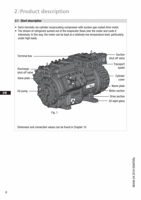
• Semi-hermetic six-cylinder reciprocating compressor with suction-gas cooled drive motor.• The stream of refrigerant sucked out of the evaporator flows over the motor and cools it intensively. In this way, the motor can be kept at a relatively low temperature level, particularly under high loads.
Fig. 1
2.1 Short description
Dimension and connection values can be found in Chapter 10
Cylinder cover
Terminal box Suctionshut-off valve
Transport eyelet
Name plate
Motor section
Drive section
Valve plate
Dischargeshut-off valve
Oil pump
Oil sight glass

D
GB
F
E
I
Ru
7
9644
6-04
.201
9-DG
bFEI
Ru
2 | Product description
2.2 Name plate (example)
2.3 Type key (example)
SE 55IP 65
BB12345-A001HGX66e/2070-4
GEA Bock GmbH72636 Frickenhausen, Germany
/HG 66 e 2070 -4 SX
¹) HG - Hermetic Gas-Cooled (suction gas-cooled) for the normal- / air conditioning applications
²) X - Ester oil charge (HFC refrigerant, e.g. R134a, R404A/R507, R407C, R407F)3) S - More powerful motor, e.g. for air-conditioning applications
Motor variant 3)
Number of poles
Swept volume
e-series
Numbers of cylinders
Size
Oil charge ²)
Series ¹)
107,0 AYY: 335,0 AY: 196,0 A
180,0
217,2
380-420 Y/YY
440-480 Y/YY
1 Type designation 6 Voltage,circuit,frequency2 Machine number 7 Nominal rotation speed3 maximum operating current 8 Displacement4 Starting current (rotor blocked) 9 Voltage,circuit,frequency Y: Part winding 1 10 Nominal rotation speed YY: Part windings 1 and 2 11 Displacement5 ND (LP): Max. admissible operating pressure 12 Oiltypefilledatthefactory (g) Low pressure side 13 Terminal box protection type HD (HP): Max. admissible operating Electrical accessories can change pressure (g) High pressure side the IP protection class! Observe the limits of application diagrams!
50 Hz}
60 Hz}
Fig. 2
8
D
GB
F
E
I
Ru
9644
6-04
.201
9-DG
bFEI
Ru
3 | Areas of application
ATTENTION Compressor operation is possible within the operating limits showninthediagrams.Pleasenotethesignificanceoftheshadedareas. Thresholds should not be selected as design or continuous operation points.- Permissible ambient temperature (-20°C) - (+60°C) - Max. permissible discharge end temperature 140°C.-Max.permissibleswitchingfrequency12x/h.- A minimum running time of 3 min. steady-state condition (continuous operation) must be achieved.For operation with supplementary cooling:- Use only oils with high thermal stability.- Avoid continuous operation near the threshold.- Additional fans (accessories) can be used for additional cooling.For operation with capacity regulator:- Continuous operation, when the capacity regulator is activated, is not permissible and can cause damage to the compressor.- The suction gas superheat temperature may need to be reduced or set individually when operating near to the threshold.- When the capacity regulator is activated, the gas velocity in the systemcannotundercertaincircumstancesensurethatsuffi- cient oil is transported back to the compressor.Foroperationwithfrequencyconverter:- The maximum current and power consumption must not be exceeded.Inthecaseofoperationabovethemainsfrequency, the application limit can therefore be limited. Max. 60 Hz.When operating in the vacuum range, there is a danger of air entering on the suction side. This can cause chemical reactions, a pressure rise in the condenser and an elevated compressed-gastemperature. Prevent the ingress of air at all costs!
3.3 Limits of application
Thecompressorsarefilledatthefactorywiththefollowingoiltype: - für R134a, R404A/R507, R407C, R407F FUCHS Reniso Triton SE 55 - für R22 FUCHS Reniso SP 46 Compressors with ester oil charge (FUCHS Reniso Triton SE 55) are marked with an X in the typedesignation (e.g. HGX66e/2070-4).
3.1 Refrigerants• HFKW / HFC: R134a, R404A/R507, R407C, R407F • (H)FCKW / (H)CFC: R22
3.2 Oil charge
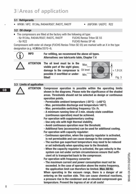
INFO For refilling, we recommend the above oil types.Alternatives: see lubricants table, Chapter 7.4
ATTENTION The oil level must be in the visible part of the sight glass; damage to the compressor is possible if overfilled or under-filled!
Max.
Min.
1,9 Ltr. Oil level
Fig. 3
~~

D
GB
F
E
I
Ru
9
9644
6-04
.201
9-DG
bFEI
Ru
3 | Areas of application
Maximum admissible operating pressure (LP/HP)1): 19/28 bar
Maximum admissible frequency:60Hz
1) LP = Low pressure HP = High pressure
Fig. 5
Fig. 6
Fig. 4
Unlimited application range
Supplementary cooling or reduced suction gas temperature
Supplementary cooling and reduced suction gas temperature
Motor version S(more powerful motor)
Evaporation temperature (°C)
Condensing temperature (°C)
Suction gas superheat (K)
Suction gas temperature (°C)
30
40
60
80
90
-20 -10 100 20 30 t (°C)o
t (°C)c
82
-30
50
70
12,5 25
20t = 20 °COh
EGD HG66e+88e
R134a
20100-10-20-30
50
70
t (°C)o
t (°C)c
-5 12,5-25
R407C
20100-10-20-30-4010
20
30
50
60
70
t (°C)o
t (°C)c
66
-35
t = 20 °Coh
-5 12,5
?t oh < 2
0 K
R22
100-10-20-30-40-50
20
30
40
50
60
70
t (°C)o
t (°C)c
?t oh
< 2
0 K
t = 20 °Coh
58
-5 7,5-45
R404A/R507
40
10
10
10
30
60
40?t Oh
<20K
t = 20 °COh
20
?t Oh < 2
0 K
R513A
R448A/R449A
20100-10-20-30-4010
20
30
50
60
70
t (°C)o
t (°C)c
t = 20 °Coh
-5 12,5
?toh
< 2
0 K
40
30
40
60
80
90
-20 -10 100 20 30 t (°C)o
t (°C)c
82
-30
50
70
12,5 25
20t = 20 °COh
10
?t Oh < 20 K
?tOh = 20 K
30
40
60
80
90
-20 -10 100 20 30 t (°C)o
t (°C)c
82
-30
50
70
12,5 25
20t = 20 °COh
EGD HG66e+88e
R134a
20100-10-20-30
50
70
t (°C)o
t (°C)c
-5 12,5-25
R407C
20100-10-20-30-4010
20
30
50
60
70
t (°C)o
t (°C)c
66
-35
t = 20 °Coh
-5 12,5
?t oh < 2
0 K
R22
100-10-20-30-40-50
20
30
40
50
60
70
t (°C)o
t (°C)c
?t oh
< 2
0 K
t = 20 °Coh
58
-5 7,5-45
R404A/R507
40
10
10
10
30
60
40?t Oh
<20K
t = 20 °COh
20
?t Oh < 2
0 K
R513A
R448A/R449A
20100-10-20-30-4010
20
30
50
60
70
t (°C)o
t (°C)c
t = 20 °Coh
-5 12,5
?toh
< 2
0 K
40
30
40
60
80
90
-20 -10 100 20 30 t (°C)o
t (°C)c
82
-30
50
70
12,5 25
20t = 20 °COh
10
?t Oh < 20 K
?tOh = 20 K
R404A/R507
R134a
R22

10
D
GB
F
E
I
Ru
9644
6-04
.201
9-DG
bFEI
Ru
3 | Areas of application
Maximum admissible operating pressure (LP/HP)1): 19/28 bar
Maximum admissible frequency:60Hz
1) LP = Low pressure HP = High pressure
Unlimited application range
Supplementary cooling or reduced suction gas temperature
Supplementary cooling and reduced suction gas temperature
Motor version S(more powerful motor)
Evaporation temperature (°C)
Condensing temperature (°C)
Suction gas superheat (K)
Suction gas temperature (°C)
30
40
60
80
90
-20 -10 100 20 30 t (°C)o
t (°C)c
82
-30
50
70
12,5 25
20t = 20 °COh
EGD HG66e+88e
R134a
20100-10-20-30
50
70
t (°C)o
t (°C)c
-5 12,5-25
R407C
20100-10-20-30-4010
20
30
50
60
70
t (°C)o
t (°C)c
66
-35
t = 20 °Coh
-5 12,5
?t oh < 2
0 K
R22
100-10-20-30-40-50
20
30
40
50
60
70
t (°C)o
t (°C)c
?t oh
< 2
0 K
t = 20 °Coh
58
-5 7,5-45
R404A/R507
40
10
10
10
30
60
40?t Oh
<20K
t = 20 °COh
20
?t Oh < 2
0 K
R513A
R448A/R449A
20100-10-20-30-4010
20
30
50
60
70
t (°C)o
t (°C)c
t = 20 °Coh
-5 12,5
?toh
< 2
0 K
40
30
40
60
80
90
-20 -10 100 20 30 t (°C)o
t (°C)c
82
-30
50
70
12,5 25
20t = 20 °COh
10
?t Oh < 20 K
?tOh = 20 K
30
40
60
80
90
-20 -10 100 20 30 t (°C)o
t (°C)c
82
-30
50
70
12,5 25
20t = 20 °COh
EGD HG66e+88e
R134a
20100-10-20-30
50
70
t (°C)o
t (°C)c
-5 12,5-25
R407C
20100-10-20-30-4010
20
30
50
60
70
t (°C)o
t (°C)c
66
-35
t = 20 °Coh
-5 12,5
?t oh < 2
0 K
R22
100-10-20-30-40-50
20
30
40
50
60
70
t (°C)o
t (°C)c
?t oh
< 2
0 K
t = 20 °Coh
58
-5 7,5-45
R404A/R507
40
10
10
10
30
60
40?t Oh
<20K
t = 20 °COh
20
?t Oh < 2
0 K
R513A
R448A/R449A
20100-10-20-30-4010
20
30
50
60
70
t (°C)o
t (°C)c
t = 20 °Coh
-5 12,5
?toh
< 2
0 K
40
30
40
60
80
90
-20 -10 100 20 30 t (°C)o
t (°C)c
82
-30
50
70
12,5 25
20t = 20 °COh
10
?t Oh < 20 K
?tOh = 20 K
30
40
60
80
90
-20 -10 100 20 30 t (°C)o
t (°C)c
82
-30
50
70
12,5 25
20t = 20 °COh
EGD HG66e+88e
R134a
20100-10-20-30
50
70
t (°C)o
t (°C)c
-5 12,5-25
R407C
20100-10-20-30-4010
20
30
50
60
70
t (°C)o
t (°C)c
66
-35
t = 20 °Coh
-5 12,5
?t oh < 2
0 K
R22
100-10-20-30-40-50
20
30
40
50
60
70
t (°C)o
t (°C)c
?t oh
< 2
0 K
t = 20 °Coh
58
-5 7,5-45
R404A/R507
40
10
10
10
30
60
40?t Oh
<20K
t = 20 °COh
20
?t Oh < 2
0 K
R513A
R448A/R449A
20100-10-20-30-4010
20
30
50
60
70
t (°C)o
t (°C)c
t = 20 °Coh
-5 12,5
?toh
< 2
0 K
40
30
40
60
80
90
-20 -10 100 20 30 t (°C)o
t (°C)c
82
-30
50
70
12,5 25
20t = 20 °COh
10
?t Oh < 20 K
?tOh = 20 K
R407C
R448A/R449A
Fig. 8
Fig. 9
R513A
Fig. 7
Designforotherareasonrequest
30
40
60
80
90
-20 -10 100 20 30 t (°C)o
t (°C)c
82
-30
50
70
12,5 25
20t = 20 °COh
EGD HG66e+88e
R134a
20100-10-20-30
50
70
t (°C)o
t (°C)c
-5 12,5-25
R407C
20100-10-20-30-4010
20
30
50
60
70
t (°C)o
t (°C)c
66
-35
t = 20 °Coh
-5 12,5
?t oh < 2
0 K
R22
100-10-20-30-40-50
20
30
40
50
60
70
t (°C)o
t (°C)c
?t oh
< 2
0 K
t = 20 °Coh
58
-5 7,5-45
R404A/R507
40
10
10
10
30
60
40?t Oh
<20K
t = 20 °COh
20
?t Oh < 2
0 K
R513A
R448A/R449A
20100-10-20-30-4010
20
30
50
60
70
t (°C)o
t (°C)c
t = 20 °Coh
-5 12,5
?toh
< 2
0 K
40
30
40
60
80
90
-20 -10 100 20 30 t (°C)o
t (°C)c
82
-30
50
70
12,5 25
20t = 20 °COh
10
?t Oh < 20 K
?tOh = 20 K
Requiredminimumsuperheating ∆tOh = 20 K
D
GB
F
E
I
Ru
11
9644
6-04
.201
9-DG
bFEI
Ru
4 | Compressor assembly
Fig. 12
Fig. 13
Fig. 14
Fig. 15
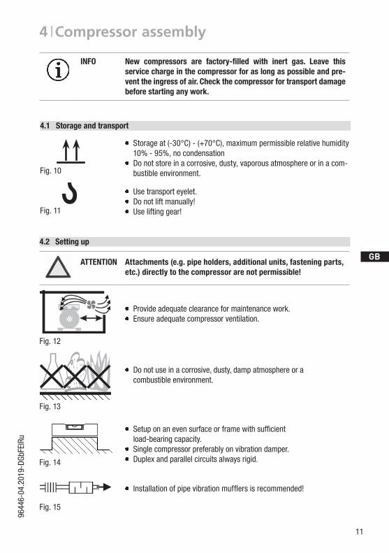
Installationofpipevibrationmufflersisrecommended!
F
E
D
C
B
A
1234
F
E
D
C
4 3 2 1
A
BTol.-Ang. DIN ISO 2768-mK
Ra Rz
Maß Passung Freigabe
Alternativbezug:Baumustergeprüft
Teil inaktiv
Lieferantenzeichnung
--
K.-Auftrag:PL:
Zeichnung ungültig
Entwicklungsstand
Teil keine Serie
120400
±0.5
über 0.5bis 6
Benzstraße 7 - 72636 Frickenhausen - Germany - www.bock.de
-
-Unbemaßte Radien:
-
Diese Zeichnung ist unser Eigentum!Sie darf ohne unsere Genehmigung weder nach-gebildet, vervielfältigt, oder Dritten Personen zu-gänglich gemacht werden. Der Nachbau nachdieser Zeichnung, oder an Hand der nach dieserZeichnung hergestellten Gegenstände durch denAbnehmer oder Dritte ist nicht gestattet.Wir behalten uns alle Rechte, gemäß DIN ISO 16016an dieser Zeichnung vor.
Bearb.DatumÄnderungs-Nr.
Werkstoff:
Ausgangsteil, bzw. Rohteil:-
-
Gepr.
NameDatum19.04.
WerkstückkantenDIN ISO 13715
Ersatz für:
Ersetzt durch:
Erstellt2010
Geprüft
-
Kurz
Zone
1/x
Oberflächenbehandlung / Härte:-
Blatt:Änderungsbeschreibung
400Benennung:
±0.8
1000 30 6
-
±0.3
12030
±0.2
Zeichn.-Nr. Teile-Nr.
Oberflächenangaben ISO 1302
x.xxxx-xxxxx.x
Zust.Gußtoleranzen:
Gewicht: (kg)
±0.1
Maßstab:
1:1
Wasserwaagefür Indesign
Der Lieferant muß sicherstellen, dass die Ware ineinwandfreiem Zustand angeliefert wird (Korrosions-schutz, Verpackung für sicheren Transport).
Rz 25Rz 160
s
25
zyxwut
0,05 Rz 1,60,30,71,62 Rz 166,3 Rz 63 Rz 6,3Rz 12,5
F:\u
ser\k
urz\
3D S
ache
n\3D
Tei
le\Z
eich
nung
en\W
asse
rwaa
ge
?Fig. 11
Fig. 10
INFO New compressors are factory-filled with inert gas. Leave this service charge in the compressor for as long as possible and pre-vent the ingress of air. Check the compressor for transport damage before starting any work.
ATTENTION Attachments (e.g. pipe holders, additional units, fastening parts, etc.) directly to the compressor are not permissible!
Setuponanevensurfaceorframewithsufficientload-bearing capacity.
Single compressor preferably on vibration damper. Duplex and parallel circuits always rigid.
Provideadequateclearanceformaintenancework. Ensureadequatecompressorventilation.
Do not use in a corrosive, dusty, damp atmosphere or a combustible environment.
4.2 Setting up
4.1 Storage and transport
Use transport eyelet. Donotliftmanually! Useliftinggear!
Storage at (-30°C) - (+70°C), maximum permissible relative humidity 10% - 95%, no condensation
Do not store in a corrosive, dusty, vaporous atmosphere or in a com-bustible environment.

12
D
GB
F
E
I
Ru
9644
6-04
.201
9-DG
bFEI
Ru
4 | Compressor assembly
Fig. 17
4.3 Pipe connections
ATTENTION Damage possible.Superheating can damage the valve. Remove the pipe supports from the valve for soldering. Only solder using inert gas to inhibit oxidation products (scale).The discharge gas connection can be moved upwards with an adapter (accessory). This makes it easier to remove the com-pressor from a refrigerating system.
Fig. 16: graduated internal diameter
Pipe connections on the compressor are available for soldering or welding (accessories). The discharge and suction line valves have graduated inside diameters so that pipes with standard millimetre and inch dimensions can be used. The pipe will be immersed more or less deeply according to dimension.
The connection diameters of the shut-off valves are rated for maximum compressor output. Theactualrequiredpipecrosssectionmustbematched to the output. The same applies for non-return valves.
4.4 Pipes
Pipes and system components must be clean and dry inside and free of scale, swarf and layers of rust and phosphate. Only use air-tight parts.
Lay pipes correctly. Suitable vibration compensators must be provided to prevent pipes being cracked and broken by severe vibrations.
Ensure a proper oil return. Keep pressure losses to an absolute minimum.
4.5 Start unloader (external)
A internal start unloader ex factory is not available. Alternatively a start unloader can be installed in the plant.
Operation:When the compressor is started, a solenoid valve receives power via a time switch and opens a by-pass between the discharge- and suction line. At the same time, a non-return valve in the discharge lineclosesandpreventsabackflowofrefrigerantfromthecondenser(Fig.17).Thecompressor isnowshort-circuitedanddeliversfromtheoutflowdirectly intotheintake.Thepressuredifferentialconsequentlydecreasessubstantially.Asaresult,thetorqueonthedriveshaftof the compressor is considerably diminished. The drive motor can now start with a low level of startingtorque.Assoonasthemotorandthecompressorreachtheirratedspeed,thesolenoidvalvecloses and the non-return valve opens (Fig. 18). The compressor now works under normal load.
Solenoid valve actuated
Non-return valve closed

D
GB
F
E
I
Ru
13
9644
6-04
.201
9-DG
bFEI
Ru
4 | Compressor assembly
Fig. 18
Rigid fixed point Fig. 19
As short as possible
4.6 Laying suction and pressure lines
A rule of thumb: Alwayslaythefirstpipesectionstartingfromtheshut-offvalvedownwardsand parallel to the drive shaft.
ATTENTION Improperly installed pipes can cause cracks and tears, the result being a loss of refrigerant.
INFO Proper layout of the suction and discharge lines directly after the compressor is integral to the system’s smooth running and vibration behaviour.
Important:
- Start unloader may only be employed during the starting phase.- Check the solenoid valve and the non-return valve regularly for tightness.- In addition, we recommend to use a heat protection thermostat on the discharge side of the com-
pressor. This protects the compressor against thermal overloading. Connect the heat protection thermostat in series on the safety chain of the control circuit, to switch off the compressor if necessary.
- Follow these instructions to avoid thermal overloading.
Solenoid valve dead
Non-return valve open

14
D
GB
F
E
I
Ru
9644
6-04
.201
9-DG
bFEI
Ru
4 | Compressor assembly
Fig. 20 Fig. 21
Valve spindle seal
Release
Tighten
Pipe connection
Pipe connection
4.8 Operating mode of the lockable service connections
Fig. 22Opening the shut-off valve:Spindle: turn to the left (counter-clockwise) as far as it will go. —> Shut-off valve completely opened / service connection closed.
Fig. 23Opening the service connectionSpindle: Turn 1/2 - 1 turn clockwise. —> Service connection opened / shut-off valve opened.
Connectionblocked
Spindle
SpindleConnectionopen
Compressor
Compressor
Service connectionclosed
Service connectionopened
Afteractivatingthespindle,generallyfitthespindleprotectioncapagainandtightenwith14-16Nm.This serves as a second sealing feature during operation.
4.7 Operating the shut-off valves
Before opening or closing the shut-off valve, release the valve spindle seal by approx. 1/4 of a turn counter-clockwise.
After activating the shut-off valve, re-tighten the adjustable valve spindle seal clockwise.
D
GB
F
E
I
Ru
15
9644
6-04
.201
9-DG
bFEI
Ru
4 | Compressor assembly
5| Electrical connection
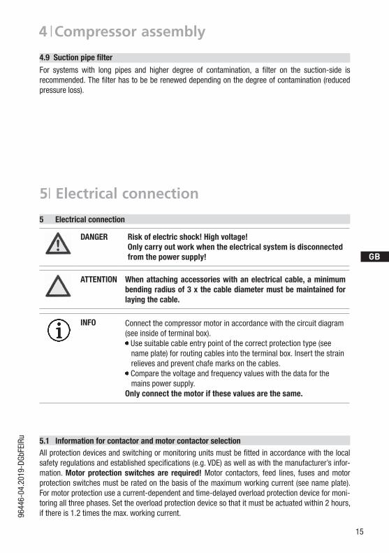
5.1 Information for contactor and motor contactor selectionAllprotectiondevicesandswitchingormonitoringunitsmustbefittedinaccordancewiththelocalsafetyregulationsandestablishedspecifications(e.g.VDE)aswellaswiththemanufacturer’sinfor-mation. Motorprotection switchesare required! Motor contactors, feed lines, fuses and motor protection switches must be rated on the basis of the maximum working current (see name plate). For motor protection use a current-dependent and time-delayed overload protection device for moni-toring all three phases. Set the overload protection device so that it must be actuated within 2 hours, if there is 1.2 times the max. working current.
INFO Connect the compressor motor in accordance with the circuit diagram (see inside of terminal box). Use suitable cable entry point of the correct protection type (see
name plate) for routing cables into the terminal box. Insert the strain relieves and prevent chafe marks on the cables.Comparethevoltageandfrequencyvalueswiththedataforthe
mains power supply. Only connect the motor if these values are the same.
DANGER Risk of electric shock! High voltage! Only carry out work when the electrical system is disconnected from the power supply!
5 Electrical connection
ATTENTION When attaching accessories with an electrical cable, a minimum bending radius of 3 x the cable diameter must be maintained for laying the cable.
For systems with long pipes and higher degree of contamination, a filter on the suction-side is recommended.Thefilterhastobebereneweddependingonthedegreeofcontamination(reducedpressure loss).
4.9Suctionpipefilter

16
D
GB
F
E
I
Ru
9644
6-04
.201
9-DG
bFEI
Ru
Designation on the name plate Sticker on the terminal box
Y/YYY/YY
5.2 Standard motor, design for direct or partial winding start
INFO A mechanical unloaded start with bypass solenoid valve is notrequired.
5| Electrical connection
Compressors with this marking are suitable for direct or partial winding start. The motor winding is subdivided into two parts: Part winding 1 = 50 % and part winding 2 = 50 %. This winding division reduces the start-up current needed for a part winding start to approx. 50 % of that for a direct start.
D
GB
F
E
I
Ru
17
9644
6-04
.201
9-DG
bFEI
Ru
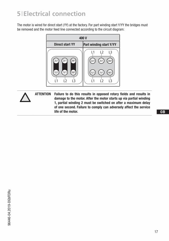
The motor is wired for direct start (YY) at the factory. For part winding start Y/YY the bridges must be removed and the motor feed line connected according to the circuit diagram:
5 | Electrical connection
ATTENTION Failure to do this results in opposed rotary fields and results indamage to the motor. After the motor starts up via partial winding 1, partial winding 2 must be switched on after a maximum delay of one second. Failure to comply can adversely affect the service life of the motor.
400 V
Direktstart YY Teilwicklungsstart Y/YY
1V1 1W11U1
2W12V12U1
L3L2L1 L3L2L1
L3L2L1
1V1 1W11U1
2W12V12U1
Direct start YY Part winding start Y/YY

18
D
GB
F
E
I
Ru
9644
6-04
.201
9-DG
bFEI
Ru
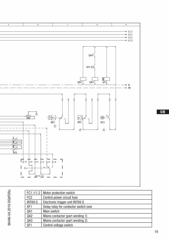
5.3 Basic circuit diagram for part winding start with standard motor
Fig. 24
Οnderung
0
Datum Name
Datum
Bearb.
Gepr.
Norm
1
20.02.2009
bauknecht
04.08.2017
Urspr.
2
Ers. f.
3
Ers. d.
4
PW INT69 HG44/66
5 6 7
BOCK COMPRESSORS
8
=
+
9
Bl.
6.c Bl.
6.a
2
Anschlußkasten Verdichter
BT1
INT69
DELTA- P II
QA1
L1 L2 L3 N PE
FC1.1
I> I>I>
QA2
1U1
1V1
1W1
PE
EC1
MY/YY
2U1
2V1
2W1
FC1.2
I> I>I>
QA3FC1.1
FC1.2
FC2
SF1
BP2
P>
QA2
BP3
P
QA2
KF1
KF1
6.c.8
QA2
L1.1L2.1L3.1L1.2
NPE
QA3
BT3
BT2Θ
1112 14L N B1 B2
121110987654321
Θ
vio bn bu gr
Θ
EB1
pk og
50% 50%
BP2 High pressure safety monitorBP3 Safety chain (high/low pressure monitoring)BT1 Cold conductor (PTC sensor) motor windingBT2 Thermal protection thermostat (PTC sensor)BT3 Release switch (thermostat)DELTA-P II Oil differential pressure sensor DELTA-P II (accessory)EB1 Oil sump heaterEC1 Compressor motor
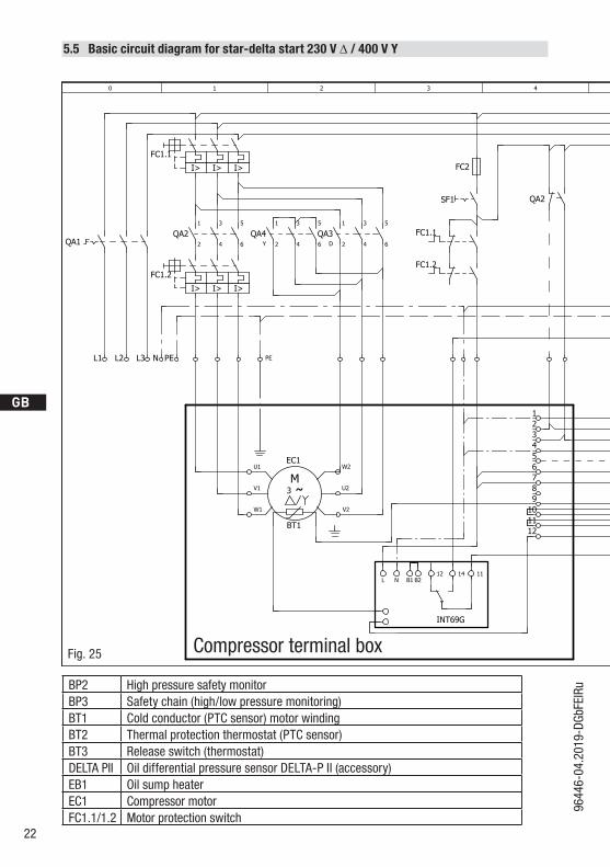
Compressor terminal box
D
GB
F
E
I
Ru
19
9644
6-04
.201
9-DG
bFEI
Ru FC1.1/1.2 Motor protection switchFC2 Control power circuit fuseINT69 G Electronic trigger unit INT69 GKF1 Delay relay for contactor switch overQA1 Main switchQA2 Mains contactor (part winding 1)QA3 Mains contactor (part winding 2)SF1 Control voltage switch
Οnderung
0
Datum Name
Datum
Bearb.
Gepr.
Norm
1
20.02.2009
bauknecht
04.08.2017
Urspr.
2
Ers. f.
3
Ers. d.
4
PW INT69 HG44/66
5 6 7
BOCK COMPRESSORS
8
=
+
9
Bl.
6.c Bl.
6.a
2
Anschlußkasten Verdichter
BT1
INT69
DELTA- P II
QA1
L1 L2 L3 N PE
FC1.1
I> I>I>
QA2
1U1
1V1
1W1
PE
EC1
MY/YY
2U1
2V1
2W1
FC1.2
I> I>I>
QA3FC1.1
FC1.2
FC2
SF1
BP2
P>
QA2
BP3
P
QA2
KF1
KF1
6.c.8
QA2
L1.1L2.1L3.1L1.2
NPE
QA3
BT3
BT2Θ
1112 14L N B1 B2
121110987654321
Θ
vio bn bu gr
Θ
EB1
pk og

20
D
GB
F
E
I
Ru
9644
6-04
.201
9-DG
bFEI
Ru
5 | Electrical connection
5.4 Special motor: design for direct or star-delta start
Amechanicalunloadedstartwithbypasssolenoidvalveisrequiredforthestar-deltastart.
Designation on the name plate Sticker on the terminal box
∆ / Y
5.4 Sondermotor: Ausführung für Direkt- oder Stern-Dreieck-Anlauf
Für den Stern-Dreieck-Anlauf ist eine mechanische Anlaufentlastung mit Bypass-Magnetventil (Zubehör) erforderlich.
Bezeichnung auf dem Typschild Aufkleber auf Klemmenkasten
∆ / Y
Stern-Dreieck-Anlauf ist nur im Spannungsbereich ∆ (230 V) möglich. Beispiel:
230 V ∆
Direktstart Stern-Dreieck-Start
L3L1
V1 W1U1
V2U2W2
L1 L2 L3
L2
V1 W1U1
V2U2W2
L3L2L1
400 V Y
nur Direktstart
V1 W1U1
V2U2W2
L1 L2 L3

D
GB
F
E
I
Ru
21
9644
6-04
.201
9-DG
bFEI
Ru
5 | Electrical connection
In the factory the motor is wired for direct starting at high voltage. The brides are to be removed for star delta starting at low voltage.
Star-delta start-up is only possible for ∆ (230 V) power supply. Example:
230 V ∆
Direct start Star-delta-start
400 V Y
Direct start only
5.4 Sondermotor: Ausführung für Direkt- oder Stern-Dreieck-Anlauf
Für den Stern-Dreieck-Anlauf ist eine mechanische Anlaufentlastung mit Bypass-Magnetventil (Zubehör) erforderlich.
Bezeichnung auf dem Typschild Aufkleber auf Klemmenkasten
∆ / Y
Stern-Dreieck-Anlauf ist nur im Spannungsbereich ∆ (230 V) möglich. Beispiel:
230 V ∆
Direktstart Stern-Dreieck-Start
L3L1
V1 W1U1
V2U2W2
L1 L2 L3
L2
V1 W1U1
V2U2W2
L3L2L1
400 V Y
nur Direktstart
V1 W1U1
V2U2W2
L1 L2 L3
22
D
GB
F
E
I
Ru
9644
6-04
.201
9-DG
bFEI
Ru
5.5 Basic circuit diagram for star-delta start 230 V ∆ / 400 V Y
Fig. 25
BP2 High pressure safety monitorBP3 Safety chain (high/low pressure monitoring)BT1 Cold conductor (PTC sensor) motor windingBT2 Thermal protection thermostat (PTC sensor)BT3 Release switch (thermostat)DELTA PII Oil differential pressure sensor DELTA-P II (accessory)EB1 Oil sump heaterEC1 Compressor motorFC1.1/1.2 Motor protection switch
Οnderung
4
0
Datum Name
Datum
Bearb.
Gepr.
Norm
1
20.02.2009
bauknecht
07.02.2018
Urspr.
2
Ers. f.
3
Ers. d.
4
D/S INT69 HG44/66 neu
5 6 7
BOCK COMPRESSORS
8
=
+
9
Bl.
6.c Bl.
6.b
6.a
Anschlußkasten Verdichter
BT1
INT69G
DELTA- P II
QA1
L1 L2 L3 N PE
U1
V1
W1
PE
U2
V2
W2
FC1.1
FC1.2
FC2
SF1
BP2
P>
BP3
P
QA2
L1.1L2.1L3.1L1.2
NPE
BT3
BT2Θ
1112 14L N B1 B2
121110987654321
Θ
vio bn bu gr pk og
Θ
1 2PE
EB1
FC1.1
I> I>I>
1
2
QA2
FC1.2
I> I>I>
3
4
5
6
1
2
QA4Y
3
4
5
6
1
2
QA3D
3
4
5
6
EC1
M3 ˜
QA2
QA2
4.7
6.b.7
QA4 KF1QA4
QA3
4.8
6.b.8
KF1QA3
QA4
4.8
6.b.8
KF1
Compressor terminal box

D
GB
F
E
I
Ru
23
9644
6-04
.201
9-DG
bFEI
Ru FC2 Control power circuit fuseINT69 G Electronic trigger unit INT69 GKF1 Delay relay for contactor switch overQA1 Main switchQA2 Mains contactorQA3 Δ-contactorQA4 Y-contactorSF1 Control voltage switchΟnderung
4
0
Datum Name
Datum
Bearb.
Gepr.
Norm
1
20.02.2009
bauknecht
07.02.2018
Urspr.
2
Ers. f.
3
Ers. d.
4
D/S INT69 HG44/66 neu
5 6 7
BOCK COMPRESSORS
8
=
+
9
Bl.
6.c Bl.
6.b
6.a
Anschlußkasten Verdichter
BT1
INT69G
DELTA- P II
QA1
L1 L2 L3 N PE
U1
V1
W1
PE
U2
V2
W2
FC1.1
FC1.2
FC2
SF1
BP2
P>
BP3
P
QA2
L1.1L2.1L3.1L1.2
NPE
BT3
BT2Θ
1112 14L N B1 B2
121110987654321
Θ
vio bn bu gr pk og
Θ
1 2PE
EB1
FC1.1
I> I>I>
1
2
QA2
FC1.2
I> I>I>
3
4
5
6
1
2
QA4Y
3
4
5
6
1
2
QA3D
3
4
5
6
EC1
M3 ˜
QA2
QA2
4.7
6.b.7
QA4 KF1QA4
QA3
4.8
6.b.8
KF1QA3
QA4
4.8
6.b.8
KF1
24
D
GB
F
E
I
Ru
9644
6-04
.201
9-DG
bFEI
Ru
5 | Electrical connection
Οnderung
Klebeschilder
0
Datum Name
Datum
Bearb.
Gepr.
Norm
1
04.12.2009
Kelich
22.05.2015
Urspr.
2
Ers. f.
3
Ers. d.
4
Schaltplan
5 6 7
BOCK COMPRESSORS
8
=
+
9
Bl.
MP10 INt69 Bl.
MP10 INt69
INT69 G Motor Protection MP10
Steuerstrom-
kreis
LN
Steuerstrom-
kreis
L N1112 14
B1 B2OG OG
+
-BT1
Θ
X1 L1 L1 N N 43 43 11 12 14L S M
X2 1 2 3 4 5 6
R1 R2
+
-BT1
Θ
+
-BT2
Θ
+
-BT2
ΘLN
Terminal boxFig. 26
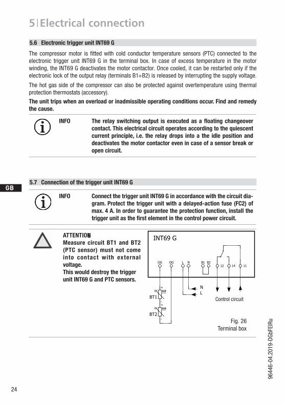
6ATTENTION Measure circuit BT1 and BT2 (PTC sensor) must not come into contact with external voltage. This would destroy the trigger unit INT69 G and PTC sensors.
5.6 Electronic trigger unit INT69 G
5.7 Connection of the trigger unit INT69 G
The compressormotor is fittedwith cold conductor temperature sensors (PTC) connected to theelectronic trigger unit INT69 G in the terminal box. In case of excess temperature in the motor winding, the INT69 G deactivates the motor contactor. Once cooled, it can be restarted only if the electronic lock of the output relay (terminals B1+B2) is released by interrupting the supply voltage.
The hot gas side of the compressor can also be protected against overtemperature using thermal protection thermostats (accessory).
The unit trips when an overload or inadmissible operating conditions occur. Find and remedy the cause.
INFO The relayswitchingoutput isexecutedasafloatingchangeover contact.Thiselectricalcircuitoperatesaccordingtothequiescent current principle, i.e. the relay drops into a the idle position and deactivates the motor contactor even in case of a sensor break or open circuit.
INFO Connect the trigger unit INT69 G in accordance with the circuit dia-gram. Protect the trigger unit with a delayed-action fuse (FC2) of max. 4 A. In order to guarantee the protection function, install the triggerunitasthefirstelementinthecontrolpowercircuit.
Control circuit

D
GB
F
E
I
Ru
25
9644
6-04
.201
9-DG
bFEI
Ru
5 | Electrical connection
5.8 Function test of the trigger unit INT69 G
Before commissioning, after troubleshooting or making changes to the control power circuit, check the functionality of the trigger unit. Perform this check using a continuity tester or gauge.
Gauge state Relay position
Deactivated state 11-12
INT69 G switch-on 11-14
Remove PTC connector 11-12
Insert PTC connector 11-12
Reset after mains on 11-14
Relay position INT69 G
B2 12 14 11
5.9 Oil sump heater (accessories)
Anschlussschema für ÖlsumpfheizungConnection diagramm for oil sump heater Plan de raccordement pour résistance de carter d‘huile
0998
3- 10
.01-D
GBF
DGBF
When the compressor is at a standstill, refrigerant diffuses into the lubricating oil of the compressors housing, depending on pressure and ambient temperature. This reduces the lubricating capacity of the oil. When the compressor starts up, the refrigerant contained in the oil evaporates out through the reductioninpressure.Theconsequencescanbefoamingandmigrationoftheoil,causingoilshocksunder certain circumstances.
Operation: The oil sump heater operates when the compressor is at a standstill. When the compres-sor starts up, the oil sump heater switches off again automatically.
Connection: The oil sump heater must be connected via an auxiliary contact (or parallel wired auxil-iary contact) of the compressor contactor to a separate electric circuit. El. data: 230 V - 1 - 50/60 Hz, 160 W.
Fig. 28
Fig. 27
ATTENTION Connection to the current path of the safety control chain is not permitted.
26
D
GB
F
E
I
Ru
9644
6-04
.201
9-DG
bFEI
Ru
6 | Commissioning
6.1 Preparations for start-up
6.4 Evacuation
First evacuate the system and then include the compressor in the evacuation process. Relieve the compressor pressure. Open the suction and pressure line shut-off valves. Evacuate the suction and discharge pressure sides using the vacuum pump. At the end of the evacuation process, the vacuum should be < 1.5 mbar when the pump is switched off. Repeatthisprocessasoftenasisrequired.
The compressor has undergone trials in the factory and all functions have been tested. There are therefore no special running-in instructions.
Check the compressor for transport damage!
6.3 Leak test
Carry out the leak test on the refrigerating plant in accordance with EN 378-2 or a corresponding safety standard, while always observing the maximum permissible overpressure for the compressor.
INFO To protect the compressor against inadmissible operating conditions, high pressure and low pressure pressostats are mandatory on the installation side.
DANGER Risk of bursting! The compressor must only be pressurised using nitrogen (N2). Never pressurise with oxygen or other gases!The maximum permissible overpressure of the compressor must not be exceeded at any time during the testing process (see name plate data)! Do not mix any refrigerant with the nitrogen as this could cause the ignition limit to shift into the critical range.
ATTENTION Do not start the compressor if it is under vacuum. Do not apply any voltage - even for test purposes (must only be operated with refrigerant).Under vacuum, the spark-over and creepage current distances of the terminal board connection bolts shorten; this can result in winding and terminal board damage.
6.2 Pressure integrity test
The compressor has been tested in the factory for pressure integrity. If however the entire system is to be subjected to a pressure integrity test, this should be carried out in accordance with EN 378-2 or a corresponding safety standard without the inclusion of the compressor.

D
GB
F
E
I
Ru
27
9644
6-04
.201
9-DG
bFEI
Ru
6| Commissioning
Make sure that the suction and pressure line shut-off valves are open.
Withthecompressorswitchedoff,addtheliquidrefrigerantdirectlytothecondenserorreceiver,breaking the vacuum.
If the refrigerant needs topping up after starting the compressor, it can be topped up in vapour formonthesuctionside,or,takingsuitableprecautions,alsoinliquidformattheinlettotheevaporator.
6.5 Refrigerant charge
CAUTION Wear personal protective clothing such as goggles and protective gloves!
ATTENTION Avoidoverfillingthesystemwithrefrigerant! To avoid shifts in concentration, zeotropic refrigerant blends must alwaysonlybefilledinto therefrigeratingplantinliquidform. Donotpourliquidcoolantthroughthesuctionlinevalveon
the compressor. It is not permissible to mix additives with the oil and
refrigerant.
6.6 Start-up
Check that the safety and protection devices (pressure switch, motor protection, electrical contact protection measures, etc.) are all functioning properly.
Switch on the compressor and allow to run for a minimum of 10 min. Check the oil level by: The oil must be visible in the sight glass.
WARNING Ensure that both shut-off valves are open before starting the compressor!
ATTENTION Iflargerquantitiesofoilhavetobetoppedup,thereisariskofoil hammer effects. If this is the case check the oil return!
6.7 Avoiding slugging
To prevent slugging: The complete refrigeration system must be properly designed. All components must be compatibly rated with each other with regard to output
(particularly the evaporator and expansion valves). Suction gas superheat at the compressor input should be min. 7 - 10 K. (check the setting
of the expansion valve). Thesystemmustreachastateofequilibrium. Particularly in critical systems (e.g. several evaporator points), measures are recommended such asreplacementofliquidtraps,solenoidvalveintheliquidline,etc. There should be no movement of coolant whatsoever while the compressor is at a standstill.
ATTENTION Slugging can damage the compressor and cause refrigerant to leak.

28
D
GB
F
E
I
Ru
9644
6-04
.201
9-DG
bFEI
Ru
HG66e / ... 1340-4 (S) 1540-4 (S) 1750-4 (S) 2070-4 (S)
Designation Item No. Item No. Item No. Item No.
Set of gaskets kit 81652 81653 81654 81655
Valve plate kit 81633 81620 81621 81622
Oil pump kit 80950
Oil sump heater kit (220-240 V) 81252
Only use genuine GEA spare parts!
7.3 Spare part recommendation
7.1 Preparation
7| Maintenance
7.2 Work to be carried out
In order to guarantee optimum operational reliability and service life of the compressor, we recommend carrying out servicing and inspection work at regular intervals: Oil change:
- not mandatory for factory-produced series systems. - forfieldinstallationsorwhenoperatingneartheapplicationlimit:forthefirsttimeafter100
to 200 operating hours, then approx. every 3 years or 10,000 - 12,000 operating hours. Dispose of used oil according to the regulations; observe national regulations.
Annual checks: Oil level, leak tightness, running noises, pressures, temperatures, function of auxiliary devices such as oil sump heater, pressure switch.
WARNING Before starting any work on the compressor: Switch off the compressor and secure it to prevent a restart. Relieve compressor of system pressure. Preventairfrominfiltratingthesystem!
After maintenance has been performed: Connect safety switch. Evacuate compressor. Release switch lock.

D
GB
F
E
I
Ru
29
9644
6-04
.201
9-DG
bFEI
Ru
7 | Maintenance
7.5 Decommissioning
Close the shut-off valves on the compressor. Drain the refrigerant (it must not be discharged into the environment) and dispose of it according to the regulations. When the compressor is depressurized, undo the fastening screws of the shut-off valves. Remove the compressor using an appropriate hoist. Dispose of the oil inside in accordance with the applicable national regulations.
7.4 Extract from the lubricants table
Theoiltypefilledasstandardinthefactoryismarkedonthename plate. This oil type should be used as a preference. Alternatives are stated in the extract from our lubricants table below.
Refrigerants GEA standard oil types Recommended alternatives
HFKW(e.g. R134a, R407C)
Fuchs Reniso Triton SE 55
Fuchs Reniso Triton SEZ 32Esso/Mobil EAL Arctic 46Sunoco Suniso SL 46Texaco Capella HFC 55
HFCKW (e.g. R22) Fuchs Reniso SP 46
Fuchs Reniso SP 32BP Energol LPT 46 Sunoco Suniso 3,5 GSTexaco Capella WF 46

30
D
GB
F
E
I
Ru
9644
6-04
.201
9-DG
bFEI
Ru
8| Accessories
8.1 Capacity regulator
Delivery condition 1 (from the factory):Cylinder cover prepared for capacity regulator.
Fig. 29 Fig. 30
LR 1
LR 2
Fig. 33
Screw in control unit (pilot valve) with sealring and tight with 15 Nm.Wet thread sides with ester oil.Insert magnetic coil, fasten it with knurlednut and connect it.
Fig. 32
ATTENTION If the capacity regulator is installed at the factory, the control component(pilotvalve)issubsequentlyinstalledandconnectedby the customer.
Before start-up, remove the cover at the capacity regulator and replace it with the enclosed control unit (pilot valve).Attention! Compressor is under pressure!Depressurize the compressor first.
Delivery condition 2 (from the factory):Capacity regulator installed with cover (transport protection).
Fig. 31
Cover
Control unit(pilot valve)
Magnetic coil
Knurled nut
Seal ring
D
GB
F
E
I
Ru
31
9644
6-04
.201
9-DG
bFEI
Ru
8| Accessories
Specialaccessoriesareonlypre-mountedinthefactoryiforderedspeciallybycustomer.Retrofittingis possible in full compliance with the safety instructions and repair instructions enclosed with the kits.Information about the use, operation, maintenance and servicing of the components is available in theprinted literature or on the internet under www.gea.com.
ATTENTION Capacity-regulated operation alters the gas speeds and pressure ratios of the refrigerating plant: Adjust the suction line routing and
dimensioning accordingly, do not set the control intervals too close and do not let the system switch more than 12 times per hour(refrigeratingplantmusthavereachedastateofequilibrium).Continuous operation in the control stage is not recommended as the gas velocity in the plant system under certain circumstances doesnotguaranteesufficientoilreturntothecompressorwithactivated capacity regulator.
We recommend switching to unregulated operation (100% capac-ity) for at least 5 minutes per capacity-regulated operating hour. An assured oil return can also be realised by a 100% capacity requirementaftereachcompressorrestart.
Electrical actuation of the solenoid valve: Normally open, (corre-sponds to 100 % compressor capacity).
WARNING Several capacity regulators cannot switch at the same time during compressor operation! Otherwise the sudden change in load can damage the compressor! Comply with the switching interval of 60 s.
• Complywiththeswitchingsequence: Switching on LR1 60s LR2
Switching off LR2 60s LR1
To prevent oil slugging: The oil return from the oil separator must be guided back at the intended connection (D1) on the
compressor housing. A direct oil return into the suction line from the oil separator is not permissible. Ensure that the oil separator is properly dimensioned.
8.2 Oil separator
ATTENTION Oil slugging can result in damage to the compressor.
32
D
GB
F
E
I
Ru
9644
6-04
.201
9-DG
bFEI
Ru
8.3 Oil level regulator
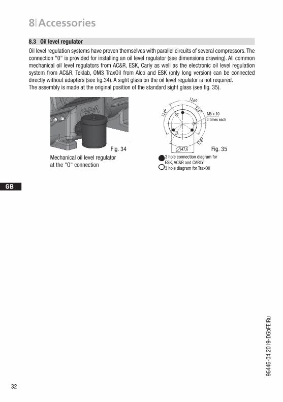
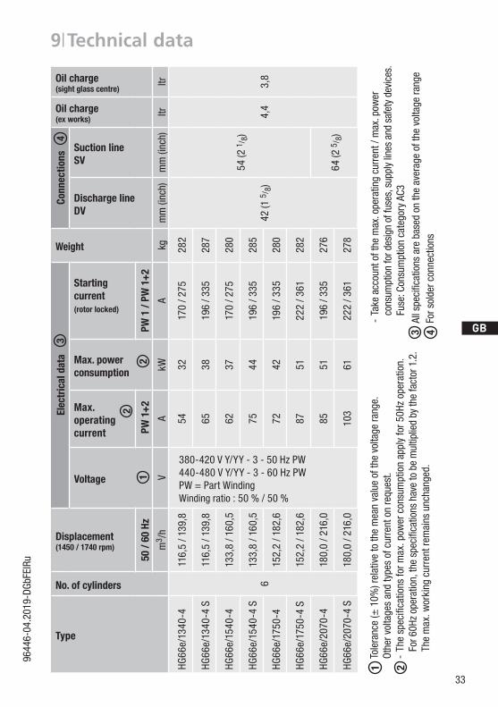
Oil level regulation systems have proven themselves with parallel circuits of several compressors. The connection "0" is provided for installing an oil level regulator (see dimensions drawing). All common mechanical oil level regulators from AC&R, ESK, Carly as well as the electronic oil level regulation system from AC&R, Teklab, OM3 TraxOil from Alco and ESK (only long version) can be connected directly without adapters (see fig.34). Asightglassontheoillevelregulatorisnotrequired.The assembly is made at the original position of the standard sight glass (see fig. 35).
Mechanical oil level regulatorat the "O" connection
Fig. 34
8| Accessories
Schmierung / Ölkontrolle Bei Inbetriebnahme Öldruckkontrolle mittels Manometer über
den Schraderanschluss an der Ölpumpe vornehmen. Nach Erreichen des Beharrungszustands (kontinuierliche
Betriebsbedingung) Ölstand des Verdichters kontrollieren. Er soll im Schauglasbereich sichtbar sein (siehe Bild).
Automatische Überwachung durch Öldifferenzdruckschalter. Bei Inbetriebnahme Funktionsprüfung des Öldifferenzdruck-schalters vornehmen.
Bei Abschaltung durch das Gerät ist eine Störanalyse vorzunehmen.Hinweise auf dem Deckel des Schalters beachten.WARNUNG! Wenn größere Ölmengen nachgefüllt werden müssen, besteht die Gefahr von Ölschlägen. In diesem Falle muss die Ölrückführung überprüft werden.
i
Anschluss ÖlspiegelregulatorBei Verbundschaltungen von mehreren Verdichtern haben sich Ölstandsregulierungssysteme bewährt. Für die Montage eines Ölspie-gelregulators ist der Anschluss „O“ vorgesehen (siehe Maßzeichnung). Alle gängigen Ölspiegelregulatoren von AC&R, ESK sowie das elek-tronische Reglersystem TRAXOIL S1A1 von SPORLAN können direkt ohne Adapter angeschlossen werden (s. Abb.). Ein Schauglas am Ölspiegelregulator ist nicht erforderlich.
124 o
124o
124 o
124o
47,6
M6 x 10je 3 mal
3-Loch-Anschlussbild für ESK, AC&R und CARLY3-Loch-Anschlussbild für TraxOil
3 hole connection diagram for ESK, AC&R and CARLY3 hole diagram for TraxOil
3 times each
Fig. 35
D
GB
F
E
I
Ru
33
9644
6-04
.201
9-DG
bFEI
Ru
Type
No. of cylinders
Displacement(1450 / 1740 rpm)
Elec
tric
al d
ata
Weight
Conn
ectio
ns
Oil charge (ex works)
Oil charge (sight glass centre)
Voltage
Max. operating current
Max. power consumption
Starting current(rotor locked)
Discharge line DV
Suction line SV
50 /
60 H
z P
W 1
+2
PW 1
/ PW
1+
2
m3 /
hV
AkW
Akg
mm
(inc
h)m
m (i
nch)
ltrltr
HG66
e/13
40-4
6
116,
5 / 1
39,8
380-420 V Y/YY - 3 - 50 Hz PW440-480 V Y/YY - 3 - 60 Hz PWPW = Part WindingWinding ratio : 50 % / 50 %
5432
170
/ 275
282
42 (1
5/ 8
)
54 (2
1/ 8
)
4,4
3,8
HG66
e/13
40-4
S11
6,5
/ 139
,865
3819
6 / 3
3528
7
HG66
e/15
40-4
133,
8 / 1
60,5
6237
170
/ 275
280
HG66
e/15
40-4
S13
3,8
/ 160
,575
4419
6 / 3
3528
5
HG66
e/17
50-4
15
2,2
/ 182
,672
4219
6 / 3
3528
0
HG66
e/17
50-4
S15
2,2
/ 182
,687
5122
2 / 3
6128
2
HG66
e/20
70-4
180,
0 / 2
16,0
8551
196
/ 335
276
64 (2
5/ 8
)HG
66e/
2070
-4 S
180,
0 / 2
16,0
103
6122
2 / 3
6127
8
9| Technical data
12
3
2
4
Tole
ranc
e (±
10%
) rel
ativ
e to
the
mea
n va
lue
of th
e vo
ltage
rang
e.Othe
rvoltage
san
dtype
sofcurrentonrequ
est.
-Th
especifica
tionsfo
rmax
.pow
ercon
sumptionap
plyfor5
0Hzop
eration.
Fo
r60H
zop
eration,th
especificatio
nshavetobemultip
liedbyth
efactor1.2.
Th
e m
ax. w
orki
ng c
urre
nt re
mai
ns u
ncha
nged
.
1 2Allspe
cific
ationsarebased
ontheaverag
eofth
evolta
gera
nge
For s
olde
r con
nect
ions
3 4 -
Take
acc
ount
of t
he m
ax. o
pera
ting
curr
ent /
max
. pow
er
cons
umpt
ion
for d
esig
n of
fuse
s, s
uppl
y lin
es a
nd s
afet
y de
vice
s.
Fu
se: C
onsu
mpt
ion
cate
gory
AC3

34
D
GB
F
E
I
Ru
9644
6-04
.201
9-DG
bFEI
Ru
10| Dimensions and connections
Fig. 36Dimensions in mm
Centre of gravity
305 381
165 107
225
205
535
Maßstab /Part-No.
--
F
E
D
C
A
F
E
D
C
4 1
A
B
5678
12345678
Zeichn.-Nr. / Drawing no. :
B
3
±0.1
Gewicht / Weight: (kg)
Gußtoleranzen / General casting tolerances:
zyxw
2251
97
über / above
Blatt /
DIN ISO 2768-mK-E
5.0000-V6072.0 0c
-
Freigabe / Approved
2
uts
-Kunde / Customer:
1.0850
Dok
-ID:
Der Lieferant muss sicherstellen, dass die Ware
packaging for safe transportation).
bis / up to
in einwandfreiem Zustand angeliefert wird
in proper conditions (corrosion prevention,
model or design.
Drawing-No.
10.01.19
Ersatz für / replacement for:
Allgemeintoleranzen / General tolerances
Transport).
prohibited. Offenders will be held liable for the
Dimension Passung / Clearance
Baumustergeprüft / Type examination:
12020H. Christner
K.-Auftrag / C.-Task:Projektleiter / Project leader:
120400±0.5
0.56
GEA Bock GmbH - Benzstraße 7 - 72636 Frickenhausen - Germany - www.bock.de
-
-
-Unbemaßte Radien / Undimensioned radii:
-
A. Layh
Bearb. / EditedDatum / DateÄnd.-Nr. / Mod-No.
Werkstoff (Zeile 2+3 alternativ) /
Base part, Raw part:
-
-
Geprüft / Appr.
Name
payment of damages. All rights reserved in the event
Material (Line 2+3 alternative):
Ausgangsteil, Rohteil /
Workpiece edgesDIN ISO 13715
Erstellt / DrawnGeprüft / Verified J. Faßbender
B. NagelDatum / Date
06.03.1815.10.18
Werkstückkanten /
Page:
400Benennung / Description:
±0.81000
30 6
-
±0.3
1/4
Oberflächenbehandlung, Härte / Treatment of surface, Hardness:
120
(Korrosionsschutz, Verpackung für sicheren
The supplier has to ensure the delivery of parts
of the grant of a patent, utility /
DIN EN ISO 1302
Zust. / Rev.
30±0.2
Zeichnungs-Nr. /
Indication of surface texture
Scale:
%
MC- HG66e/2070-4 S
Rz 25Rz 160 Rz 1,6Rz 16Rz 63 Rz 6,3Rz 12,5Status:
-
-
in Bearbeitung (CAD)
Nein / No 11496 .0
MK- HG66e/2070-4 S
-
Weitergabe sowie Vervielfältigung dieses Dokuments, Verwertung und Mitteilung seines Inhalts sind ver-boten, soweit nicht ausdrücklich gestattet. Zuwider-handlungen verpflichten zu Schadenersatz. Alle Rechte für den Fall der Patent-, Gebrauchsmuster- oder Geschmacksmustereintragung vorbehalten. The reproduction, distribution and utilization of this document as well as the communication of its contents to others without express authorization is
Maß
Oberflächenangaben /
Teile-Nr. /
A. Layh
B1
JÖV
L
F,M
C
K,O
DX
DV
W
360
175
+2
15
557
4x
467
+2
Typ /type
Teile-Nr. /part-no.
Typ /type
Teile-Nr. /part-no.
Typ /type
Teile-Nr. /part-no.
Typ /type
Teile-Nr. /part-no.
Typ /type
Teile-Nr. /part-no.
Typ /type
Teile-Nr. /part-no.
HG66e/1340-4 11482 HGX66e/1340-4 11483 HG66e/1340-4 S 11484 HGX66e/1340-4 S 11485 HG66e/1340-4 HC 11498 HG66e/1340-4 S HC 11499
HG66e/1540-4 11486 HGX66e/1540-4 11487 HG66e/1540-4 S 11488 HGX66e/1540-4 S 11489 HG66e/1540-4 HC 11500 HG66e/1540-4 S HC 11501
HG66e/1750-4 11490 HGX66e/1750-4 11491 HG66e/1750-4 S 11492 HGX66e/1750-4 S 11493 HG66e/1750-4 HC 11502 HG66e/1750-4 S HC 11503
HG66e/2070-4 11494 HGX66e/2070-4 11495 HG66e/2070-4 S 11496 HGX66e/2070-4 S 11497 HG66e/2070-4 HC 11504 HG66e/2070-4 S HC 11505
Halbhermetischer Verdichter HG / Semi-hermetic compressor HG
1.0850-11496.0
Maße in mmDimensions in mm
Änderungen vorbehaltenSubject to change without notice
MassenschwerpunktCentre of gravity
Anschlüsse /Connections
HG66e/1340-4 (S) 1540-4 (S) 1750-4 (S)
HG66e/2070-4 (S)
SVSaugabsperrventil, Rohr (L)* mm - Zoll
54 – 2 1/8" 64 – 2 5/8"Suction line valve, tube (L)* mm - inch
DVDruckabsperrventil, Rohr (L)* mm - Zoll
42 - 1 5/8"Discharge line valve, tube (L)* mm - inch
AAnschluss Saugseite, nicht absperrbar
Zoll / inch 1/8" NPTFConnection suction side, not lockable
A1Anschluss Saugseite, absperrbar
Zoll / inch 7/16" UNFConnection suction side, lockable
BAnschluss Druckseite, nicht absperrbar
Zoll / inch 1/8" NPTFConnection discharge side, not lockable
B1Anschluss Druckseite, absperrbar
Zoll / inch 7/16" UNFConnection discharge side, lockable
CAnschluss Öldrucksicherheitsschalter OIL
Zoll / inch 1/8" NPTFConnection oil pressure safety switch OIL
DAnschluss Öldrucksicherheitsschalter LP
Zoll / inch 7/16" UNFConnection oil pressure safety switch LP
D1Anschluss Ölrückführung vom Ölabscheider
Zoll / inch 1/4" NPTFConnection oil return from oil separator
FÖlablass
mm M12x1,5Oil drain
HStopfen Ölfüllung
Zoll / inch 1/4" NPTFOil charge plug
JAnschluss Ölsumpfheizung
Zoll / inch 3/8" NPTFConnection oil sump heater
KSchauglas
mm 3xM6Sight glass
LAnschluss Wärmeschutzthermostat
Zoll / inch 1/8" NPTFConnection thermal protection thermostat
MÖlsieb
mm M12x1,5Oil filter
OAnschluss Ölspiegelregulator
mm 3xM6Connection oil level regulator
ÖVAnschluss Ölserviceventil
Zoll / inch 1/4" NPTFConnection oil service valve
QAnschluss Öltemperatursensor
Zoll / inch 1/8" NPTFConnection oil temperature sensor
WAnschluss Kältemittel Einspritzung
Zoll / inch 2x1/8" NPTFConnection for refrigerant injection(L)* = Lötanschluss(L)* = Brazing connection
L,B
Q W
H,D1
A
Y
402
810 +2
404
SchwingungsdämpferVibration absorbers
M12 30
25
50
A1Y
SVW
Ansicht X: Anschlussmöglichkeit für Ölspiegelregulator / View X: Possibility of connection of oil level regulator
Dreilochanschluss für TRAXOIL (3xM6x10) / Three-hole connection for TRAXOIL (3xM6x10) Dreilochanschluss für ESK, AC+R, CARLY (3xM6x10) / Three-hole connection for ESK, AC+R, CARLY (3xM6x10)
Vibration absorbers

D
GB
F
E
I
Ru
35
9644
6-04
.201
9-DG
bFEI
Ru
10| Dimensions and connections
SVDV
Suction lineDischarge line see technical data, chapter 9
A Connection suction side, not lockable 1/8“ NPTF
A1 Connection suction side, lockable 7/16“ UNF
B Connection discharge side, not lockable 1/8“ NPTF
B1 Connection discharge side, lockable 7/16“ UNF
C Connection oil pressure safety switch OIL 1/8“ NPTF
D Connection oil pressure safetyswitch LP 7/16“ UNF
D1 Connection oil return from oil separator 1/4“ NPTF
F Oil drain M12x1,5
H Oil charge plug 1/4“ NPTF
J Connection oil sump heater 3/8“ NPTF
K Sight glass 3 x M6
L Connection thermal protection thermostat 1/8“ NPTF
M Oilfilter M12x1,5
O Connection oil level regulator 3 x M6
ÖV Connection oil service valve 1/4“ NPTF
Q Connection oil temperature sensor 1/8“ NPTF
W Connection for refrigerant injection 2x 1/8“ NPTF
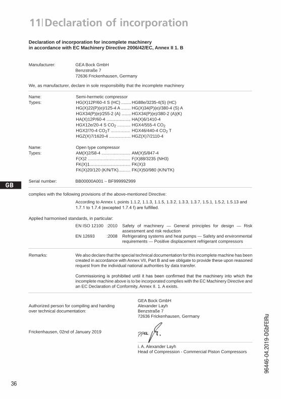
36
D
GB
F
E
I
Ru
9644
6-04
.201
9-DG
bFEI
Ru
11| Declaration of incorporation
9645
7 06
-201
9 DG
bFEI
TrPt
Ru
Declaration of incorporation for incomplete machineryin accordance with EC Machinery Directive 2006/42/EC, Annex II 1. B
Manufacturer: GEA Bock GmbH Benzstraße 7 72636 Frickenhausen, Germany
We, as manufacturer, declare in sole responsibility that the incomplete machinery
Name: Semi-hermetic compressor Types: HG(X)12P/60-4 S (HC) ........ HG88e/3235-4(S) (HC) HG(X)22(P)(e)/125-4 A ........ HG(X)34(P)(e)/380-4 (S) A HGX34(P)(e)/255-2 (A) ........ HGX34(P)(e)/380-2 (A)(K) HA(X)12P/60-4 .................... HA(X)6/1410-4 HGX12e/20-4 S CO2 ........... HGX4/555-4 CO2 HGX2/70-4 CO2T ................ HGX46/440-4 CO2 T HGZ(X)7/1620-4 .................. HGZ(X)7/2110-4
Name: Open type compressor Types: AM(X)2/58-4 ........................ AM(X)5/847-4 F(X)2 ................................... F(X)88/3235 (NH3) FK(X)1.................................. FK(X)3 FK(X)20/120 (K/N/TK).......... FK(X)50/980 (K/N/TK)
Serial number: BB00000A001 – BF99999Z999
complies with the following provisions of the above-mentioned Directive:
According to Annex I, points 1.1.2, 1.1.3, 1.1.5, 1.3.2, 1.3.3, 1.3.7, 1.5.1, 1.5.2, 1.5.13 and 1.7.1to1.7.4(excepted1.7.4f)arefulfilled.
Applied harmonised standards, in particular:
EN ISO 12100 :2010 Safety of machinery — General principles for design — Risk assessment and risk reduction EN 12693 :2008 Refrigerating systems and heat pumps — Safety and environmental requirements — Positive displacement refrigerant compressors
Remarks: We also declare that the special technical documentation for this incomplete machine has been created in accordance with Annex VII, Part B and we obligate to provide these upon reasoned request from the individual national authorities by data transfer.
Commissioning isprohibiteduntil ithasbeenconfirmed that themachinery intowhich the incomplete machine above is to be incorporated complies with the EC Machinery Directive and an EC Declaration of Conformity, Annex II. 1. A exists.
GEA Bock GmbHAuthorized person for compiling and handing Alexander Layhover technical documentation: Benzstraße 7 72636 Frickenhausen, Germany
Frickenhausen, 02nd of January 2019
i. A. Alexander Layh Head of Compression - Commercial Piston Compressors
D
GB
F
E
I
Ru
37
9644
6-04
.201
9-DG
bFEI
Ru
Dear customer,
GEAcompressorsaretop-quality,reliableandservice-friendlyqualityproducts. Ifyouhaveanyquestionsaboutinstallation,operationandaccessories,pleasecontactourtechnicalservice or specialist wholesaler and/or our representative. The GEA service team can be contacted by phone with a toll-free hotline 00 800 / 800 000 88 or via e-mail: [email protected]
Yours faithfully
GEA Bock GmbH
Benzstraße 7
72636 Frickenhausen
Germany
12| Service

We live our values.Excellence • Passion • Integrity • Responsibility • GEA-versity
GEA Bock GmbH
Benzstraße 7
72636 Frickenhausen, Germany
Phone +49 (0)7022 9454-0
Fax +49 (0)7022 9454-137
gea.com
GEA Group is a global engineering company with multi-billion euro sales and operations in more
than 50 countries. Founded in 1881, the company is one of the largest providers of innovative
equipment and process technology. GEA Group is listed in the STOXX® Europe 600 index.