gear measuring machine by "ndg method" for gears ranging from
TRANSCRIPT
www.geartechnology.com March/April 2011 GEARTECHNOLOGY 55continued
Management SummaryA study was conducted on the development of a CNC gear measuring machine for measuring involute tooth profile
by a new measurement method. Involute tooth profile measurement has been done, until now, by almost always using two-axis control in which the probe moves only in the X-axis direction synchronously with the gear rotation angle (θ). In contrast, the newly developed measurement method uses three-axis control in which the probe moves along the line of action under control in two orthogonal, axial directions (along the X and Y axes) synchronously with the gear rota-tion angle (θ).
This new method enables high-accuracy measurement because the small X-direction movement of the probe reduces the guaranteed accuracy range and minimizes movement of the probing head gravity center. As probe movement in the X-direction is unaffected by gear outside diameter, the advantage of the new method over earlier ones is particularly relevant to the measurement of super-large gears. While conventional measurement methods must use multiple probes to avoid probe-tooth interference in the measurement of inner gears, the new method uses fewer probes in inner gear measurement and eliminates the need for an automatic tool changer (ATC). In the case of a small-diameter inner gear (outside circle diameter of 10 mm or less), measurement of tooth profile, helix and pitch deviation can be completed with a one-time set-ting. A CNC gear measuring system is developed using this new measurement method that provides numerous advantages over conventional measuring systems.
Gear Measuring Machine by “NDG Method”
for Gears Ranging from Miniature to Super-Large
Masatoshi Yuzaki
“This is an interesting concept and should be of interest to your readers.”—Robert E. Smith
Robert E. Smith is president of R.E. Smith & Co. Inc., a gear consultancy in Rochester, NY. A mechanical engineer, he has more than 60 years’ experience in the gear industry. He is chairman of the AGMA Calibration Committee and was AGMA’s ISO delegate for that panel as well as for the AGMA Inspection and Handbook Committee. Since 1991, he has vol-unteered his services as a Gear Technology technical editor. As Bob was the technical reviewer of this article, we believe his comments regarding this paper’s relevance will be of in-terest to readers. (The Editors)
“This is an interesting concept and should be of interest to your readers. As the author points out, it has several advan-tages over the conventional TDG method. When reducing the X axis movement while checking large-diameter gears, the potential errors of probe positioning are reduced. Also, the instrument can be smaller in that direction. There are definite advantages to checking small-diameter internal gears, also.
While the conventional instruments go “back to basics” and measure normal to the tooth surface at the base circle tan-gent, (the author’s) NDG method has the probe moving in a direction that is not normal to the surface. He therefore has to make a correction to all measurements involving the co-sine of the transverse pressure angle. However, that is not a problem. Gear measurements on a CMM-type instrument have to be corrected in a similar way to the surface normals. When we established our National Gear Metrology labora-tory at Oak Ridge, we had them measure artifacts by the first principles (TDG) method in order to compare to CMM-type measurements that required algorithms for probe corrections. We were satisfied that the results were good and the differ-ences were insignificant. All artifacts today are measured by the CMM instruments. In this case, the author did compare measurements by both TDG and NDG systems, on the same gear, and showed the results to be the same. It was done on a gear of approximately 13-inch diameter, but I would expect good results on much larger gears also. In fact, the error, or uncertainty of measurement, should be (even) less on larger gears.”
GEARTECHNOLOGY March/April 2011 www.geartechnology.com56
Figure 2―Typical tooth form measurement
X
Y
Base Circle
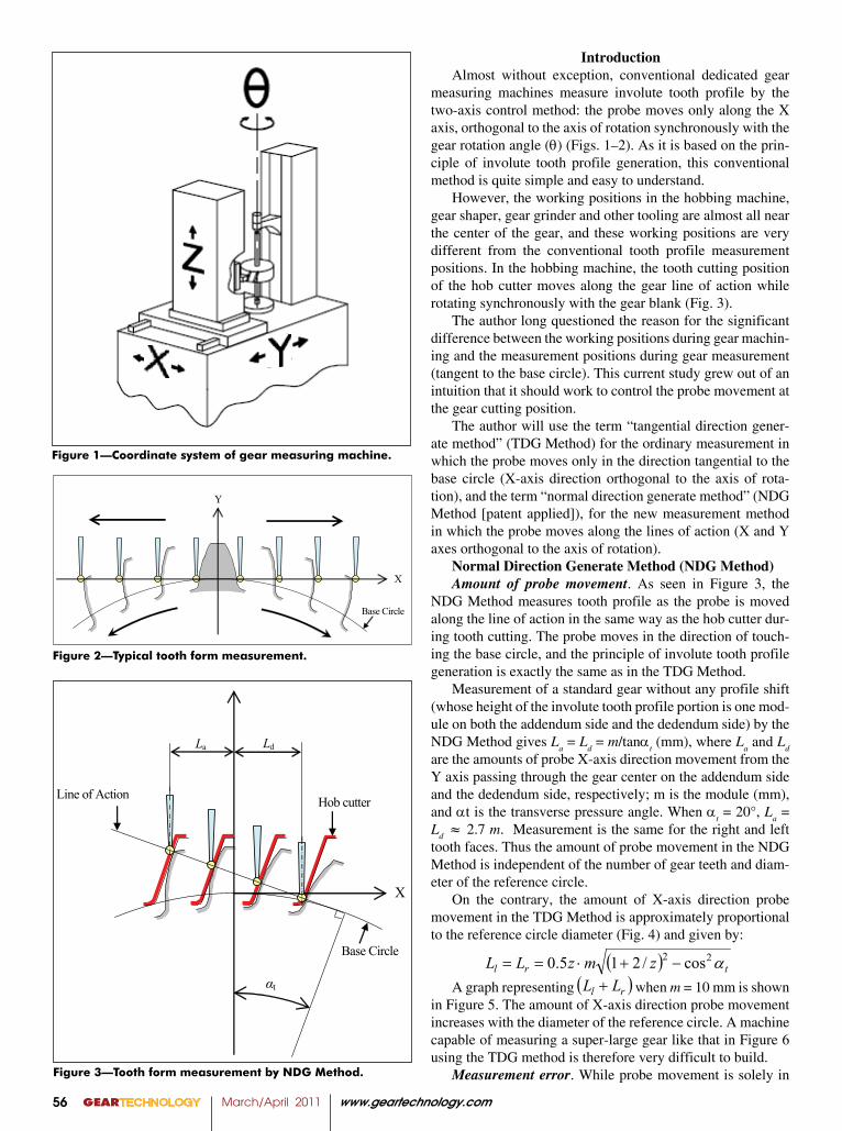
Figure 2—Typical tooth form measurement.
Figure 3―Tooth form measurement by NDG-Method
Base Circle
X
Line of Action
αt
La Ld
Hob cutter
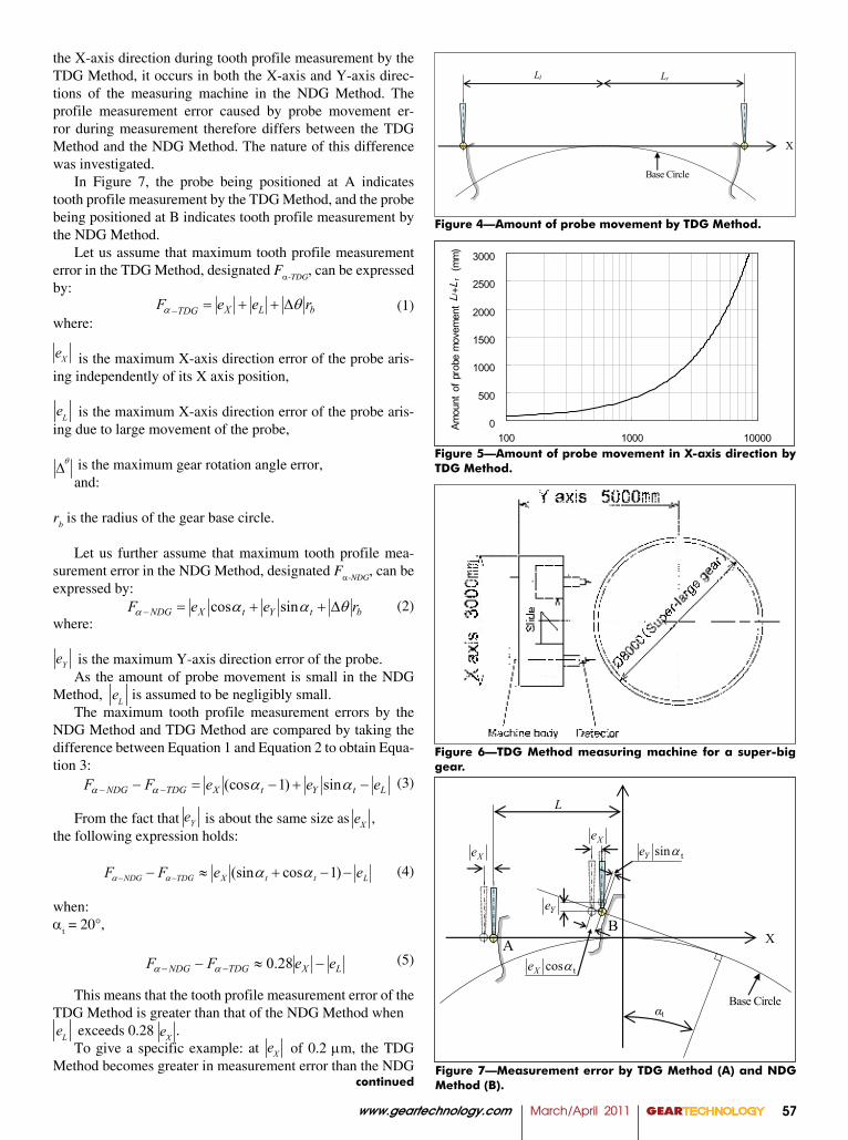
Figure 3—Tooth form measurement by NDG Method.
( ) trl zmzLL α22 cos/215.0 −+⋅==( )rl LL +
IntroductionAlmost without exception, conventional dedicated gear
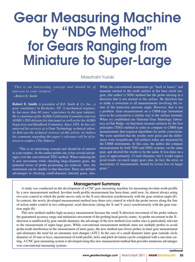
measuring machines measure involute tooth profile by the two-axis control method: the probe moves only along the X axis, orthogonal to the axis of rotation synchronously with the gear rotation angle (θ) (Figs. 1–2). As it is based on the prin-ciple of involute tooth profile generation, this conventional method is quite simple and easy to understand.
However, the working positions in the hobbing machine, gear shaper, gear grinder and other tooling are almost all near the center of the gear, and these working positions are very different from the conventional tooth profile measurement positions. In the hobbing machine, the tooth cutting position of the hob cutter moves along the gear line of action while rotating synchronously with the gear blank (Fig. 3).
The author long questioned the reason for the significant difference between the working positions during gear machin-ing and the measurement positions during gear measurement (tangent to the base circle). This current study grew out of an intuition that it should work to control the probe movement at the gear cutting position.
The author will use the term “tangential direction gener-ate method” (TDG Method) for the ordinary measurement in which the probe moves only in the direction tangential to the base circle (X-axis direction orthogonal to the axis of rota-tion), and the term “normal direction generate method” (NDG Method [patent applied]), for the new measurement method in which the probe moves along the lines of action (X and Y axes orthogonal to the axis of rotation).
Normal Direction Generate Method (NDG Method)Amount of probe movement. As seen in Figure 3, the
NDG Method measures tooth profile as the probe is moved along the line of action in the same way as the hob cutter dur-ing tooth cutting. The probe moves in the direction of touch-ing the base circle, and the principle of involute tooth profile generation is exactly the same as in the TDG Method.
Measurement of a standard gear without any profile shift (whose height of the involute tooth profile portion is one mod-ule on both the addendum side and the dedendum side) by the NDG Method gives L
a = L
d = m/tanα
t (mm), where L
a and L
d
are the amounts of probe X-axis direction movement from the Y axis passing through the gear center on the addendum side and the dedendum side, respectively; m is the module (mm), and αt is the transverse pressure angle. When α
t = 20°, L
a =
Ld ≈ 2.7 m. Measurement is the same for the right and left
tooth faces. Thus the amount of probe movement in the NDG Method is independent of the number of gear teeth and diam-eter of the reference circle.
On the contrary, the amount of X-axis direction probe movement in the TDG Method is approximately proportional to the reference circle diameter (Fig. 4) and given by:
A graph representing when m = 10 mm is shown in Figure 5. The amount of X-axis direction probe movement increases with the diameter of the reference circle. A machine capable of measuring a super-large gear like that in Figure 6 using the TDG method is therefore very difficult to build.
Measurement error. While probe movement is solely in
Figure 1—Coordinate system of gear measuring machine.
www.geartechnology.com March/April 2011 GEARTECHNOLOGY 57
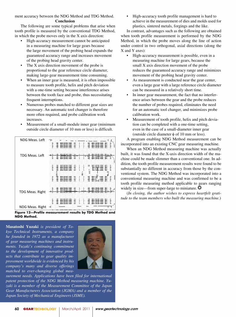
the X-axis direction during tooth profile measurement by the TDG Method, it occurs in both the X-axis and Y-axis direc-tions of the measuring machine in the NDG Method. The profile measurement error caused by probe movement er-ror during measurement therefore differs between the TDG Method and the NDG Method. The nature of this difference was investigated.
In Figure 7, the probe being positioned at A indicates tooth profile measurement by the TDG Method, and the probe being positioned at B indicates tooth profile measurement by the NDG Method.
Let us assume that maximum tooth profile measurement error in the TDG Method, designated Fα-TDG
, can be expressed by:
(1)where:
is the maximum X-axis direction error of the probe aris-ing independently of its X axis position,
is the maximum X-axis direction error of the probe aris-ing due to large movement of the probe,
is the maximum gear rotation angle error,and:
rb is the radius of the gear base circle.
Let us further assume that maximum tooth profile mea-surement error in the NDG Method, designated Fα-NDG
, can be expressed by:
(2)where:
is the maximum Y-axis direction error of the probe. As the amount of probe movement is small in the NDG
Method, is assumed to be negligibly small.The maximum tooth profile measurement errors by the
NDG Method and TDG Method are compared by taking the difference between Equation 1 and Equation 2 to obtain Equa-tion 3:
(3)
From the fact that is about the same size as , the following expression holds:
(4)
when:αt = 20°,
(5)
This means that the tooth profile measurement error of the TDG Method is greater than that of the NDG Method when
exceeds 0.28 .To give a specific example: at of 0.2 mm, the TDG
Method becomes greater in measurement error than the NDG
Figure 4―Amount of probe movement by TDG-Method
X
Base Circle
Ll Lr
Figure 4—Amount of probe movement by TDG Method.
0
500
1000
1500
2000
2500
3000
100 1000 10000Reference pitch diameter (mm)
Amou
nt o
f pro
be m
ovem
ent L
l +L r
(m
m)
Figure 5—Amount of probe movement in X-axis direction by TDG Method.
Figure 6—TDG Method measuring machine for a super-big gear.
bLXTDG reeF θα ∆−
btYtXNDG reeF θααα ∆− sincos
LtYtXTDGNDG eeeFF −−− −− αααα sin)1(cos
LttXTDGNDG eeFF −−≈− −− )1cos(sin αααα
LXTDGNDG eeFF −≈− −− 28.0αα
bLXTDG reeF θα ∆−
btYtXNDG reeF θααα ∆− sincos
LtYtXTDGNDG eeeFF −−− −− αααα sin)1(cos
LttXTDGNDG eeFF −−≈− −− )1cos(sin αααα
LXTDGNDG eeFF −≈− −− 28.0αα
bLXTDG reeF θα ∆−
btYtXNDG reeF θααα ∆− sincos
LtYtXTDGNDG eeeFF −−− −− αααα sin)1(cos
LttXTDGNDG eeFF −−≈− −− )1cos(sin αααα
LXTDGNDG eeFF −≈− −− 28.0αα
bLXTDG reeF θα ∆−
btYtXNDG reeF θααα ∆− sincos
LtYtXTDGNDG eeeFF −−− −− αααα sin)1(cos
LttXTDGNDG eeFF −−≈− −− )1cos(sin αααα
LXTDGNDG eeFF −≈− −− 28.0αα
bLXTDG reeF θα ∆−
btYtXNDG reeF θααα ∆− sincos
LtYtXTDGNDG eeeFF −−− −− αααα sin)1(cos
LttXTDGNDG eeFF −−≈− −− )1cos(sin αααα
LXTDGNDG eeFF −≈− −− 28.0αα
Figure 7―Measurement Error by TDG-Method (A) and NDG-Method (B)
Base Circle
X
Xe
αt
A B
L
Ye
XetsinαYe
tcosαXe
Figure 7—Measurement error by TDG Method (A) and NDG Method (B).
Xe
Le
θ∆
Xe
Le
θ∆
Xe
Le
θ∆
Ye
Le
Ye
Le
Ye
Le
Xe
Le
θ∆
Ye
Le Xe
Le
θ∆
Xe
Le
θ∆
continued

GEARTECHNOLOGY March/April 2011 www.geartechnology.com58
indicates measurement of inner gear tooth profile by the TDG Method. When a probe of small tip diameter is used, interfer-ence occurs between the tooth tip and the probe stem. If an at-tempt is made to avoid interference between the tooth tip and probe stem by enlarging the probe tip diameter, interference will then occur between the probe tip and the opposite tooth face. Although this problem can be overcome by removing one side of the probe tip, it would require the probe orien-tation to be reversed laterally when measuring the opposite tooth face.
On the other hand—as shown in Figure 8B—measure-ment by the NDG Method does not experience interference between the tooth tip and probe, no matter how much probe tip diameter is reduced. The left and right tooth faces can therefore be measured with a single, small probe. The effi-cacy of the NDG Method is therefore particularly evident in the measurement of small-diameter, inner gears (ϕ 10 mm or less).
Probe tip position. It should also be noted regarding mea-surement by the NDG Method that it differs from that of the TDG Method not only in the direction of probe movement, but also—depending on the probe type—in the initial probe position.
Figure 9 shows an example in which the probe has a spherical tip. In the TDG Method—indicated by A in the drawing—the center of the tip sphere is positioned on the X axis, where the measurement is performed. In the NDG Meth-od—indicated by B in the drawing—the center of the probe tip sphere is positioned at the intercept of the reference circle and the Y axis, and measurement is performed along the line of action at pressure angle α
t.
Figure 10 shows an example in which the probe has a chisel type tip. In the TDG Method—indicated by A in the drawing—the tip of the chisel is positioned on the X axis, where the measurement is performed. In the NDG Method—indicated by B in the drawing—the axis of the probe stem is aligned with the Y axis and the chisel tip must be moved from the intercept of the reference circle and the Y axis toward the gear center by tp tan)2/( αd , where d
p is the tip diameter of the
Table 1—Specifications of the Developed NDG Measuring Machine
Machine
Test Mode profile, lead, pitchfor spur/helical gear, internal gearwith auto alignment system
Size 4,300 x 1,200 x 3,400 mm
Weight 6,000 kg
Measurement accuracy
0.1 mm
Gear
Module 1.0 to 32 mm
Outer diameter (max)
2,000 mm
Face width (max)
1,500 mm
Helix angle (max)
±65 deg
Shaft length 150 to 2,000 mm
Weight (max) 10,000 kg
Figure 8―Measurement of inner gear by TDG-Method (A) and NDG-Method (B)
Y
X A
B
Base Circle Tooth tip
Figure 8—Measurement of inner gear by TDG-Method (A) and NDG-Method (B).
Figure 9―Measurement by sphere tip probe
Base Circle
X A
B
αt
Reference Circle
Line of Action
Figure 9—Measurement by sphere tip probe.
Method when becomes 0.056 mm or larger. In a machine for measuring super-large gears, it is extremely difficult to achieve a probe movement error of less than 0.056 mm. The NDG Method is therefore better than the TDG Method for measuring super-large gears.
Measurement of inner gear. When an inner gear is mea-sured by the TGD Method, it becomes impossible to measure tooth profile, helix and pitch deviation with a one-time setting because interference arises between the tooth face and probe, thereby causing frequent interruptions.
In Figure 8, the case where the probe is positioned at A
Ye
Le

www.geartechnology.com March/April 2011 GEARTECHNOLOGY 59
chisel type probe..NDG Measuring Machine
A measuring machine utilizing the newly developed NDG Method is shown in Figure 11. The specifications of the developed measuring machine are provided in Table 1. The X axis direction width of the measuring machine can be slimmed down considerably, compared with one adopting the conventional system.
In the measuring machine using the NDG Method, the probe is controlled in orthogonal, two-axis (X and Y) direc-tion at a given angle to move along the line of action. It should therefore be noted that the tooth profile error output of the probe—which has sensitivity in the X axis direction—is the cosine (cos) of the transverse pressure angle. In other words, the tooth profile error must be multiplied by the displacement
output (1/cosαt). And, as mentioned previously, the probe
must be initially positioned so that the measurement point falls on the line of action.
Measurement ResultThe dimensions of a gear for test measurement are shown
in Table 2.NDG Method measurement is performed near the gear
center, analogous with the working positions in a gear man-ufacturing machine. This makes measurement possible in a much shorter time than by the TDG Method. A comparison of measurement times using the same developed measuring machine showed that the NDG Method achieved a time re-duction of 35% for profile measurement, compared with the TDG Method.
Figure 12 and Table 3 show the results when tooth pro-file measurement is conducted by the NDG Method and TDG Method in the same developed measuring machine. The re-sults show that there is no substantial difference in measure-
Figure 10―Measurement by chisel tip probe
Base Circle
X A
B Reference Circle
φdp
tp tan
2α
d
Figure 10—Measurement by chisel tip probe.
Figure 11—Developed NDG measuring machine.
Table 2—Gear Dimensions for Test MeasurementModule 5 mmNumber of teeth 60Outer Diameter 329.5 mmPressure Angle 20 degHelix Angle 20 degGear Width 50 mm
Table 3—Profile Deviations by TDG-Method and NDG-Method
Unit:mmLeft Flank Right Flank
Fα ffα fHα Fα ffα fHα
TDG 3.8 1.7 -3.4 2.4 0.7 -2.4
NDG 3.8 1.7 -3.4 2.4 0.7 -2.4
continued
GEARTECHNOLOGY March/April 2011 www.geartechnology.com60
Masatoshi Yuzaki is president of To-kyo Technical Instruments, a company he founded in 1972 as a manufacturer of gear measuring machines and instru-ments. Yuzaki’s continuing commitment to the development of innovative prod-ucts that contribute to gear quality im-provement worldwide is evidenced by his company’s many and diverse offerings matched to ever-changing global mea-surement needs. Applications have been filed for international patent protection of the NDG Method measuring machine. Yu-zaki is a member of the Measurement Committee of the Japan Gear Manufacturers Association (JGMA) and a member of the Japan Society of Mechanical Engineers (JSME).
ment accuracy between the NDG Method and TDG Method.Conclusion
The following are some typical problems that arise when tooth profile is measured by the conventional TDG Method, in which the probe moves only in the X axis direction:
• High-accuracy measurement cannot be anticipated in a measuring machine for large gears because the large movement of the probing head expands the
guaranteed accuracy range and increases movement of the probing head gravity center.• The X axis direction movement of the probe is proportional to the gear reference circle diameter,
making large-gear measurement time consuming.• When an inner gear is measured, it is often impossible to measure tooth profile, helix and pitch deviation with a one-time setting because interference arises between the tooth face and probe, thus necessitating frequent interruptions.• Numerous probes matched to different gear sizes are necessary. An automatic tool changer is therefore more often required, and probe calibration work increases.• Measurement of a small-module inner gear (minimum outside circle diameter of 10 mm or less) is difficult.
TDG Meas. Left
NDG Meas. Left
TDG Meas. Right
NDG Meas. Right Figure 12—Profile measurement results by TDG Method and NDG Method.
• High-accuracy tooth profile management is hard to achieve in the measurement of dies and molds used for plastics, sintered metals, forgings and the like.In contrast, advantages such as the following are obtained
when tooth profile measurement is performed by the NDG Method, in which the probe moves along the line of action under control in two orthogonal, axial directions (along the X and Y axes):
• High-accuracy measurement is possible, even in a measuring machine for large gears, because the small X axis direction movement of the probe
reduces the guaranteed accuracy range and minimizes movement of the probing head gravity center.• As measurement is conducted near the gear center, even a large gear with a large reference circle diameter can be measured in a relatively short time.• In inner gear measurement, the fact that no interfer- ence arises between the gear and the probe reduces the number of probes required, eliminates the need for an automatic tool changer, and minimizes probe
calibration work.• Measurement of tooth profile, helix and pitch devia- tion can be completed with a one-time setting,
even in the case of a small-diameter inner gear (outside circle diameter φ of 10 mm or less).A program enabling NDG Method measurement can be
incorporated into an existing CNC gear measuring machine.When an NDG Method measuring machine was actually
built, it was found that the X-axis direction width of the ma-chine could be made slimmer than a conventional one. In ad-dition, the tooth profile measurement results were found to be substantially no different in accuracy from those by the con-ventional system. The NDG Method was incorporated into a conventional measuring machine and was confirmed to be a tooth profile measuring method applicable to gears ranging widely in size—from super-large to miniature.
(In closing, the author wishes to express heartfelt grati-tude to the team members who built the measuring machine.)