gearbox manual dg400 2017 - drenth-gearboxes.com · dg400 –revision: 007 gearbox manual 2 pole...
TRANSCRIPT
Gearbox Manual DG400
2017
2 Gearbox Manual DG400 – Revision: 007
Pole Position
In Gearboxes
Warning Please be aware that information in this manual may be inaccurate, incomplete or contain typographical errors. The content of this manual is subject to
change without notice and should, therefore, be used for informational purposes only. Consequently, replacement parts must always by ordered according
to the part number engraved on the part.
If you find information in this manual that is incorrect or incomplete, we would appreciate your comments and suggestions.
3 Gearbox Manual DG400 – Revision: 007
Pole Position
In Gearboxes
Contents Warning ............................................................................................................................................................................................................................................. 2
Contents ............................................................................................................................................................................................................................................ 3
1. Technical Specifications................................................................................................................................................................................................................. 5
1.1. General Specifications ............................................................................................................................................................................................................ 6
1.2. General Dimensions ................................................................................................................................................................................................................ 7
1.3. Oil System ............................................................................................................................................................................................................................... 8
2. Gearbox Assembly ......................................................................................................................................................................................................................... 9
2.1. General Instruction Notes..................................................................................................................................................................................................... 10
2.2. Bearing Assembly .................................................................................................................................................................................................................. 11
2.3. BMW Gearbox Assembly ...................................................................................................................................................................................................... 13
2.4. Ford Gearbox Assembly ....................................................................................................................................................................................................... 32
2.5. Oil Pump Assembly (Old Type) ............................................................................................................................................................................................. 38
2.6 Oil Pump Assembly (Updated Type) ...................................................................................................................................................................................... 40
2.6. Heavy Duty ............................................................................................................................................................................................................................ 43
2.7. Rotary Sensor ........................................................................................................................................................................................................................ 49
3. Gear Ratio List ............................................................................................................................................................................................................................. 51
4. Accessories .................................................................................................................................................................................................................................. 53
4.1. Bellhousings / Adaptor Plates ............................................................................................................................................................................................... 54
4.2. Gearbox Brackets .................................................................................................................................................................................................................. 57
4.3. Gear Lever ............................................................................................................................................................................................................................. 59
4.4. DMS Gear Lever .................................................................................................................................................................................................................... 61
4.5. Gear lever Brackets ............................................................................................................................................................................................................... 63
4.6. Gear Indicator ....................................................................................................................................................................................................................... 64
4 Gearbox Manual DG400 – Revision: 007
Pole Position
In Gearboxes
4.7. Display Unit ........................................................................................................................................................................................................................... 65
4.8. Switchbox .............................................................................................................................................................................................................................. 66
4.9. Oil Breather Catchtank ......................................................................................................................................................................................................... 67
4.10. Paddleshift System ............................................................................................................................................................................................................. 68
5. Assembly Tooling ......................................................................................................................................................................................................................... 70
6. Contact Information .................................................................................................................................................................................................................... 72
6.1. Contact Details ...................................................................................................................................................................................................................... 73
Appendix A: Technical Bulletins ...................................................................................................................................................................................................... 74
Appendix B: Amendments ............................................................................................................................................................................................................... 76

5 Gearbox Manual DG400 – Revision: 007
Pole Position
In Gearboxes
1. Technical Specifications
6 Gearbox Manual DG400 – Revision: 007
Pole Position
In Gearboxes
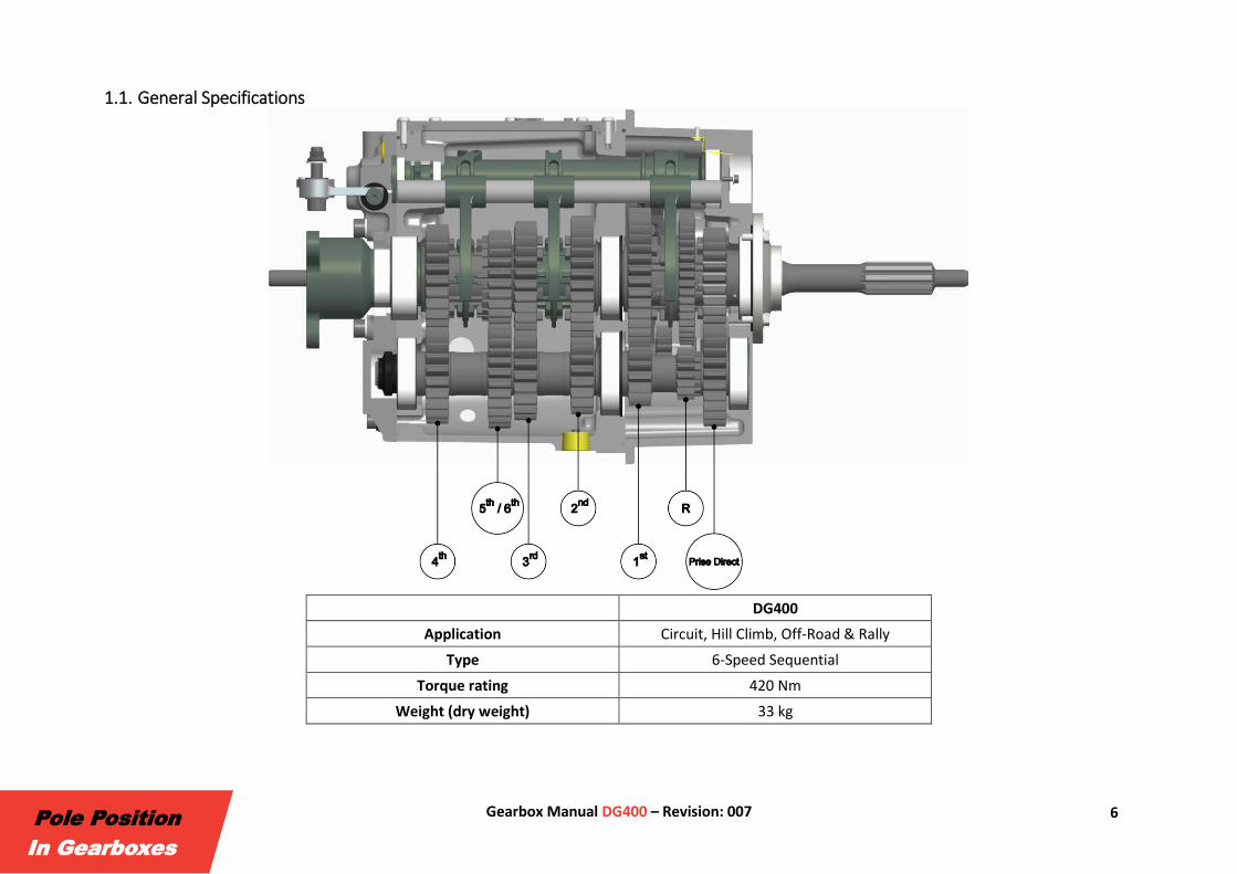
1.1. General Specifications
DG400
Application Circuit, Hill Climb, Off-Road & Rally
Type 6-Speed Sequential
Torque rating 420 Nm
Weight (dry weight) 33 kg
7 Gearbox Manual DG400 – Revision: 007
Pole Position
In Gearboxes
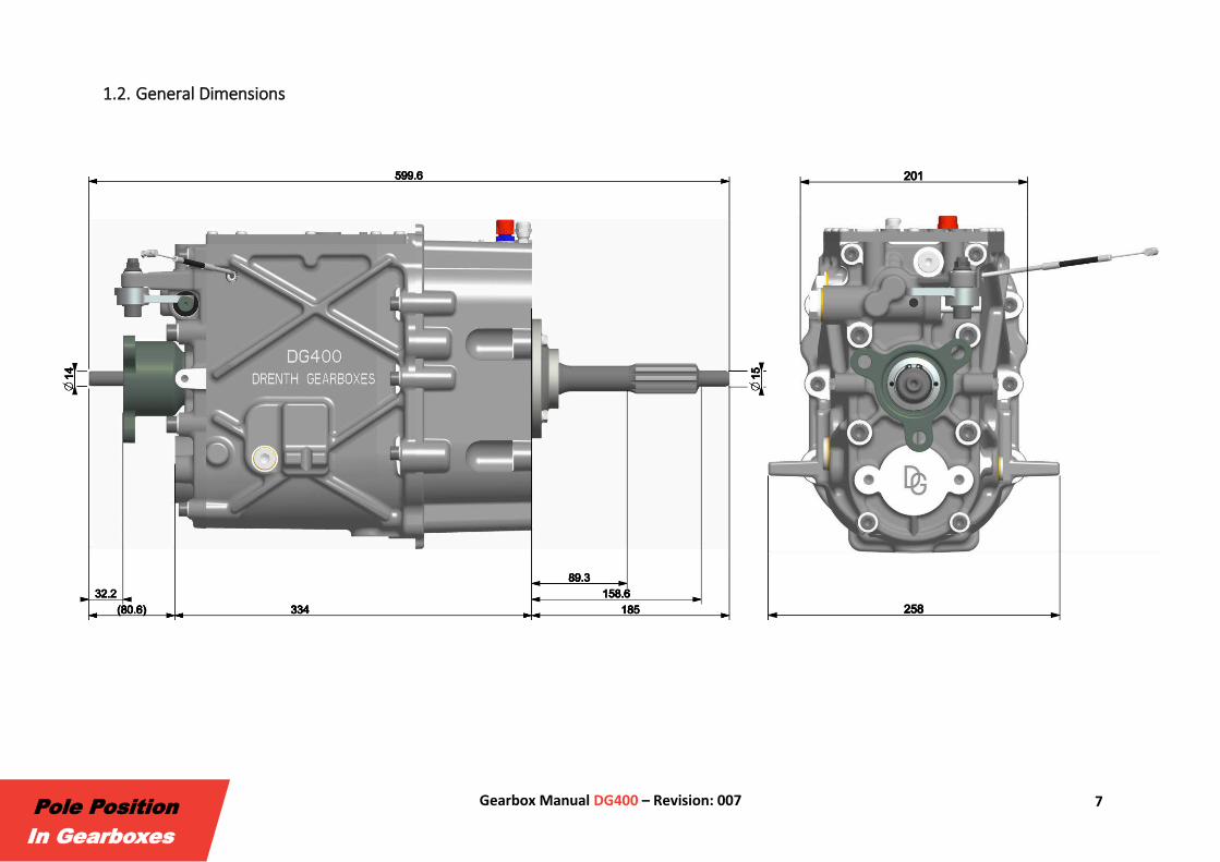
1.2. General Dimensions
8 Gearbox Manual DG400 – Revision: 007
Pole Position
In Gearboxes
1.3. Oil System A gerotor internal-gear pump can be fitted in the end cover of the DG400 optionally. The oil pump is used to feed oil to the bearings, gears, dog rings and
drop gears. The oil can be fed to an external oil cooler from the oil-out port and returned to the gearbox using the oil-in port. On the right and left side of
the main housing an M12x1.50 thread is provided to mount oil temperature and pressure sensors. On top of the gearbox a D-06 adaptor is mounted which
needs to be connected to an oil catch tank or has to be replaced with a breather.
Oil Type Motul 75W140 Gear Competition
Oil Quantity 1.25 litres (excluding external oil lines & oil cooler)

9 Gearbox Manual DG400 – Revision: 007
Pole Position
In Gearboxes
2. Gearbox Assembly
10 Gearbox Manual DG400 – Revision: 007
Pole Position
In Gearboxes
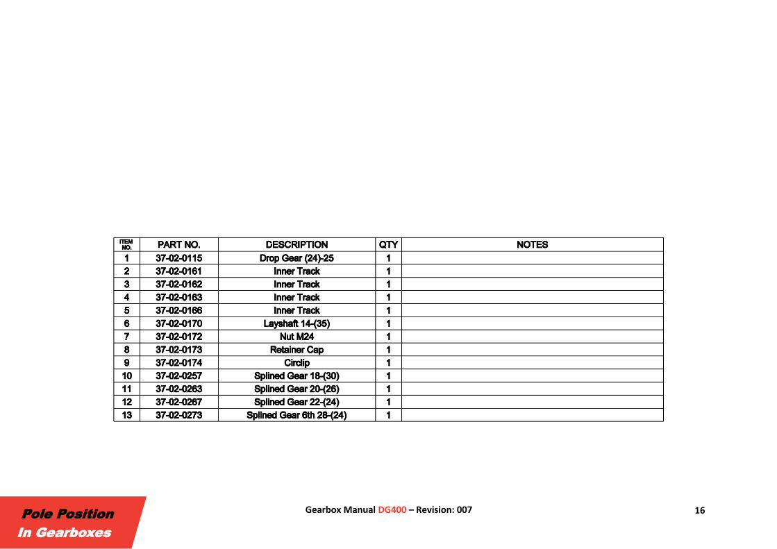
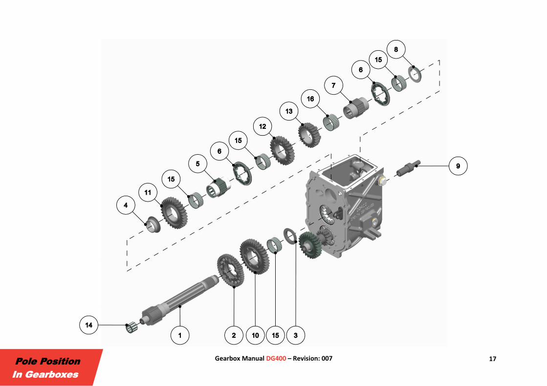
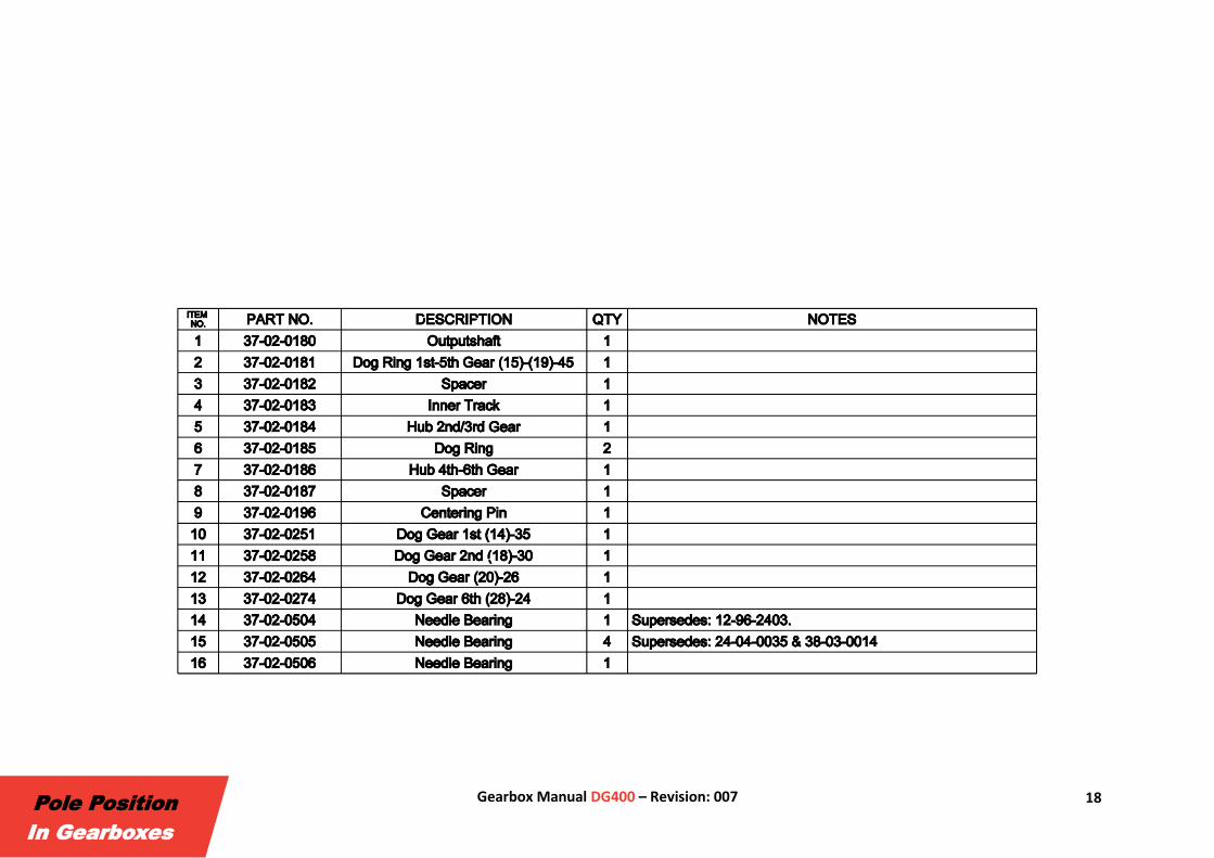
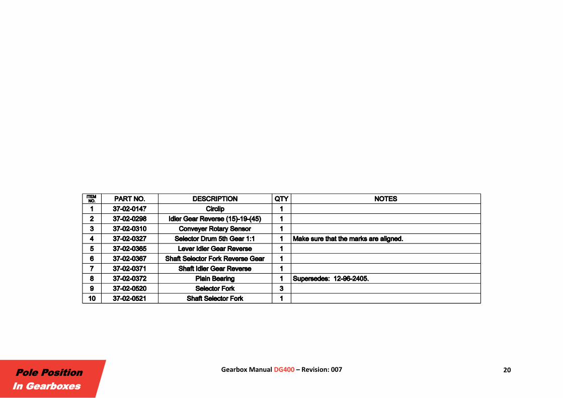
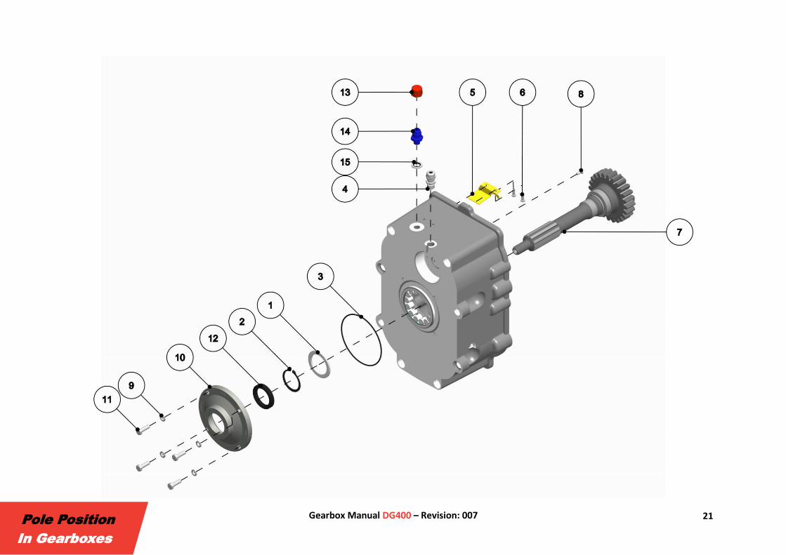
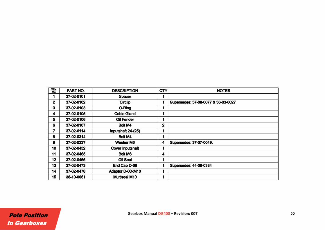
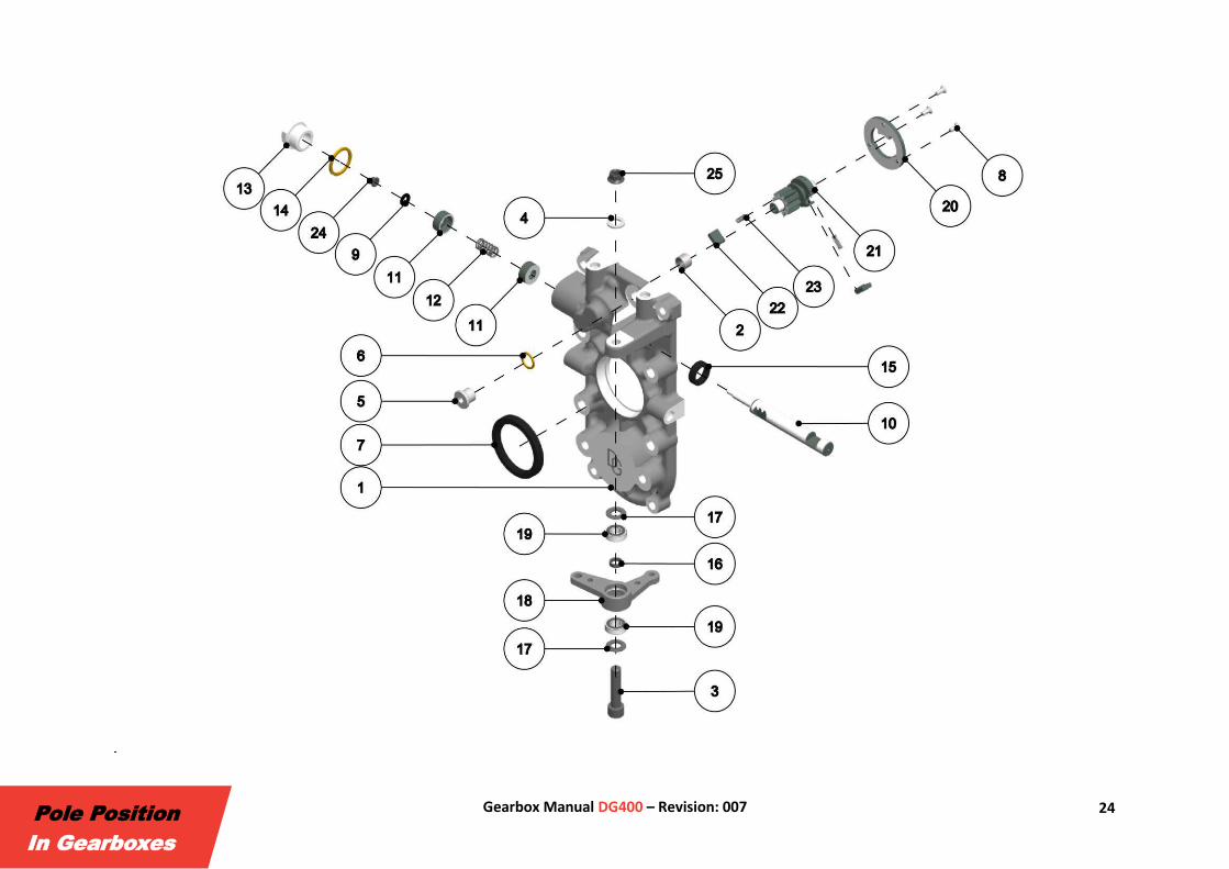
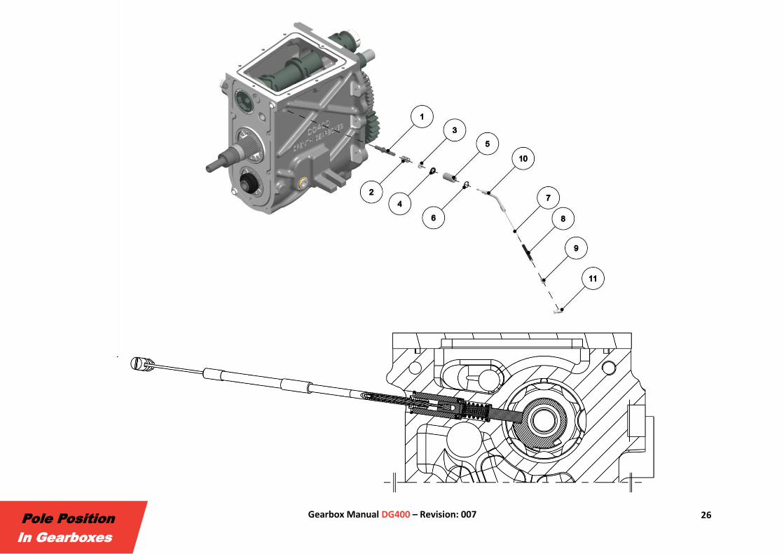
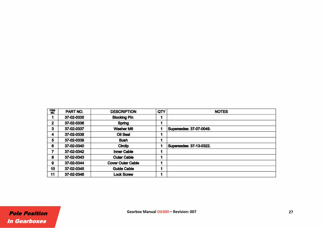
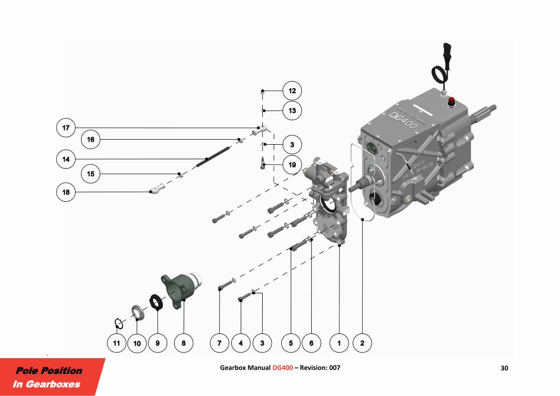
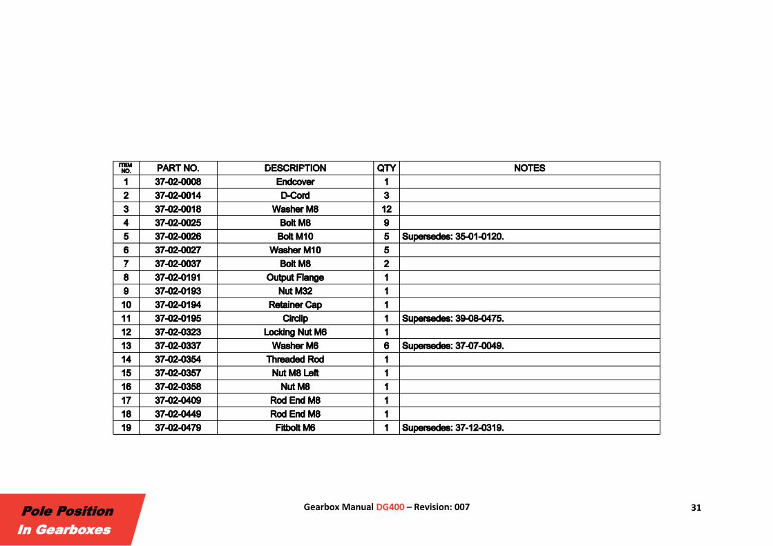
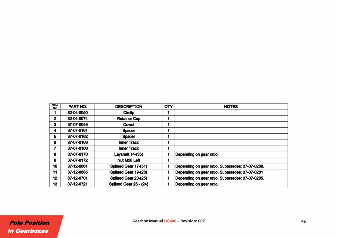
2.1. General Instruction Notes The following information is intended for mechanics to (dis)assemble the gearbox. This is illustrated using exploded views including the corresponding Bill Of
Materials (BOM). Specific notes related to the (dis)assembly of a part are shown in the notes column of the BOM. For more details on the bearing
installation see §2.2 Bearing Assembly.
Please read the manual and make sure all parts are present before starting to assemble. Also ensure that all parts are clean and undamaged. It is
recommended to replace nuts, seals and circlips after removal. Only genuine Drenth Gearboxes parts should be used when overhauling the gearbox.
11 Gearbox Manual DG400 – Revision: 007
Pole Position
In Gearboxes
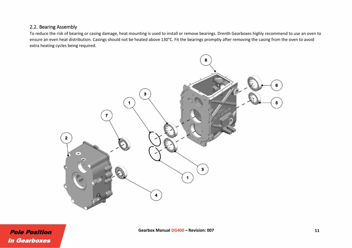
2.2. Bearing Assembly To reduce the risk of bearing or casing damage, heat mounting is used to install or remove bearings. Drenth Gearboxes highly recommend to use an oven to
ensure an even heat distribution. Casings should not be heated above 130°C. Fit the bearings promptly after removing the casing from the oven to avoid
extra heating cycles being required.

12 Gearbox Manual DG400 – Revision: 007
Pole Position
In Gearboxes
13 Gearbox Manual DG400 – Revision: 007
Pole Position
In Gearboxes
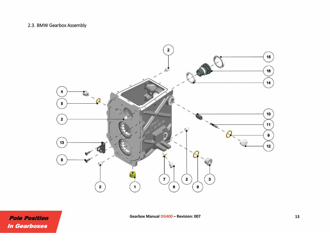
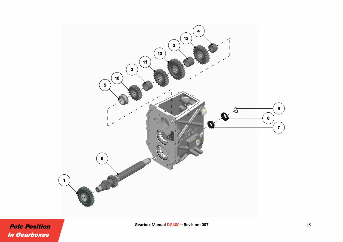
2.3. BMW Gearbox Assembly
14 Gearbox Manual DG400 – Revision: 007
Pole Position
In Gearboxes
15 Gearbox Manual DG400 – Revision: 007
Pole Position
In Gearboxes
16 Gearbox Manual DG400 – Revision: 007
Pole Position
In Gearboxes
17 Gearbox Manual DG400 – Revision: 007
Pole Position
In Gearboxes
18 Gearbox Manual DG400 – Revision: 007
Pole Position
In Gearboxes

19 Gearbox Manual DG400 – Revision: 007
Pole Position
In Gearboxes
20 Gearbox Manual DG400 – Revision: 007
Pole Position
In Gearboxes
21 Gearbox Manual DG400 – Revision: 007
Pole Position
In Gearboxes
22 Gearbox Manual DG400 – Revision: 007
Pole Position
In Gearboxes
23 Gearbox Manual DG400 – Revision: 007
Pole Position
In Gearboxes
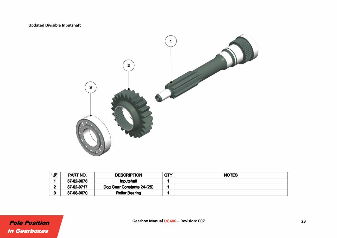
Updated Divisible Inputshaft
24 Gearbox Manual DG400 – Revision: 007
Pole Position
In Gearboxes

25 Gearbox Manual DG400 – Revision: 007
Pole Position
In Gearboxes
26 Gearbox Manual DG400 – Revision: 007
Pole Position
In Gearboxes
27 Gearbox Manual DG400 – Revision: 007
Pole Position
In Gearboxes

28 Gearbox Manual DG400 – Revision: 007
Pole Position
In Gearboxes

29 Gearbox Manual DG400 – Revision: 007
Pole Position
In Gearboxes
30 Gearbox Manual DG400 – Revision: 007
Pole Position
In Gearboxes
31 Gearbox Manual DG400 – Revision: 007
Pole Position
In Gearboxes

32 Gearbox Manual DG400 – Revision: 007
Pole Position
In Gearboxes
2.4. Ford Gearbox Assembly
33 Gearbox Manual DG400 – Revision: 007
Pole Position
In Gearboxes

34 Gearbox Manual DG400 – Revision: 007
Pole Position
In Gearboxes

35 Gearbox Manual DG400 – Revision: 007
Pole Position
In Gearboxes

36 Gearbox Manual DG400 – Revision: 007
Pole Position
In Gearboxes

37 Gearbox Manual DG400 – Revision: 007
Pole Position
In Gearboxes
38 Gearbox Manual DG400 – Revision: 007
Pole Position
In Gearboxes
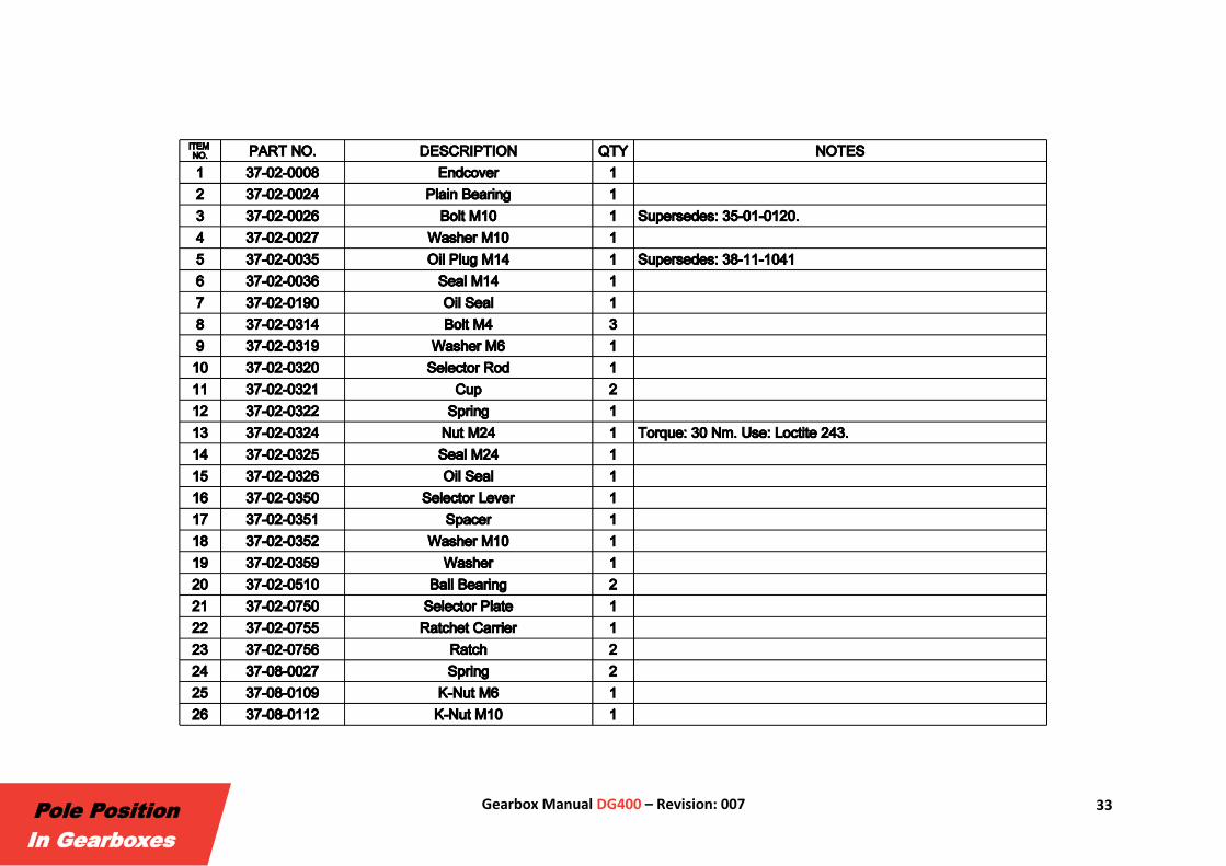
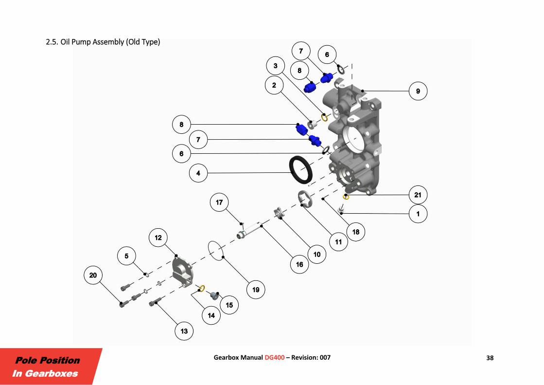
2.5. Oil Pump Assembly (Old Type)

39 Gearbox Manual DG400 – Revision: 007
Pole Position
In Gearboxes

40 Gearbox Manual DG400 – Revision: 007
Pole Position
In Gearboxes
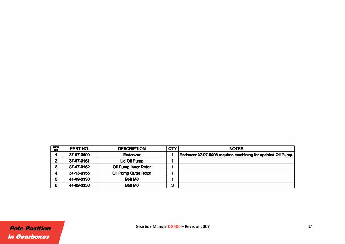
2.6 Oil Pump Assembly (Updated Type)
41 Gearbox Manual DG400 – Revision: 007
Pole Position
In Gearboxes

42 Gearbox Manual DG400 – Revision: 007
Pole Position
In Gearboxes
43 Gearbox Manual DG400 – Revision: 007
Pole Position
In Gearboxes
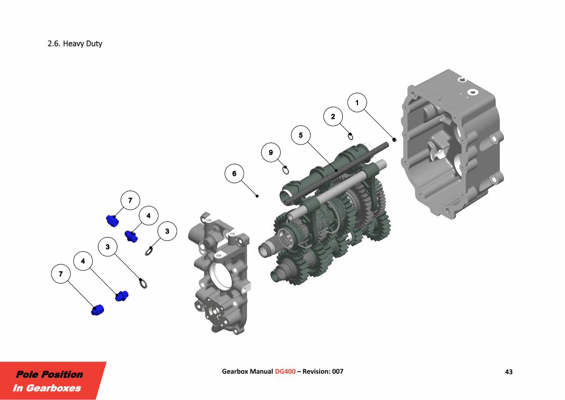
2.6. Heavy Duty

44 Gearbox Manual DG400 – Revision: 007
Pole Position
In Gearboxes

45 Gearbox Manual DG400 – Revision: 007
Pole Position
In Gearboxes
46 Gearbox Manual DG400 – Revision: 007
Pole Position
In Gearboxes

47 Gearbox Manual DG400 – Revision: 007
Pole Position
In Gearboxes

48 Gearbox Manual DG400 – Revision: 007
Pole Position
In Gearboxes
49 Gearbox Manual DG400 – Revision: 007
Pole Position
In Gearboxes
2.7. Rotary Sensor
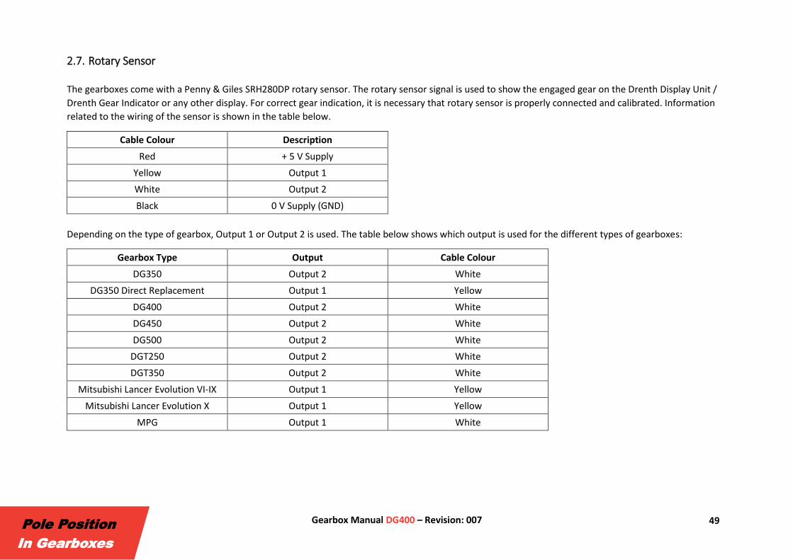
The gearboxes come with a Penny & Giles SRH280DP rotary sensor. The rotary sensor signal is used to show the engaged gear on the Drenth Display Unit /
Drenth Gear Indicator or any other display. For correct gear indication, it is necessary that rotary sensor is properly connected and calibrated. Information
related to the wiring of the sensor is shown in the table below.
Cable Colour Description
Red + 5 V Supply
Yellow Output 1
White Output 2
Black 0 V Supply (GND)
Depending on the type of gearbox, Output 1 or Output 2 is used. The table below shows which output is used for the different types of gearboxes:
Gearbox Type Output Cable Colour
DG350 Output 2 White
DG350 Direct Replacement Output 1 Yellow
DG400 Output 2 White
DG450 Output 2 White
DG500 Output 2 White
DGT250 Output 2 White
DGT350 Output 2 White
Mitsubishi Lancer Evolution VI-IX Output 1 Yellow
Mitsubishi Lancer Evolution X Output 1 Yellow
MPG Output 1 White
50 Gearbox Manual DG400 – Revision: 007
Pole Position
In Gearboxes
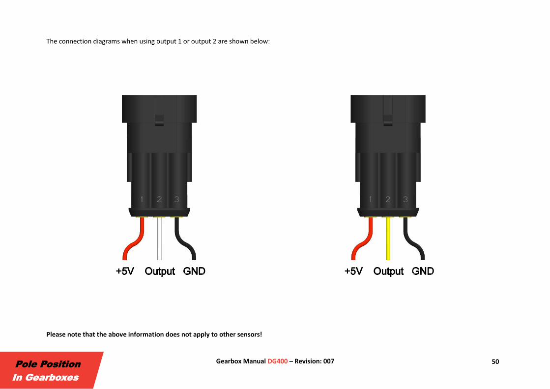
The connection diagrams when using output 1 or output 2 are shown below:
Please note that the above information does not apply to other sensors!

51 Gearbox Manual DG400 – Revision: 007
Pole Position
In Gearboxes
3. Gear Ratio List
52 Gearbox Manual DG400 – Revision: 007
Pole Position
In Gearboxes
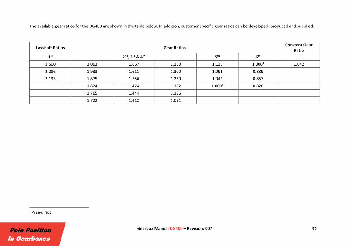
The available gear ratios for the DG400 are shown in the table below. In addition, customer specific gear ratios can be developed, produced and supplied.
Layshaft Ratios Gear Ratios Constant Gear
Ratio
1st 2nd, 3rd & 4th 5th 6th
2.500 2.063 1.667 1.350 1.136 1.0001 1.042
2.286 1.933 1.611 1.300 1.091 0.889
2.133 1.875 1.556 1.250 1.042 0.857
1.824 1.474 1.182 1.0001 0.828
1.765 1.444 1.136
1.722 1.412 1.091
1 Prise-direct

53 Gearbox Manual DG400 – Revision: 007
Pole Position
In Gearboxes
4. Accessories

54 Gearbox Manual DG400 – Revision: 007
Pole Position
In Gearboxes
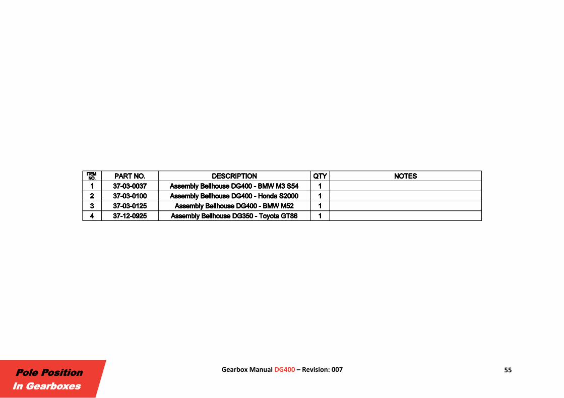
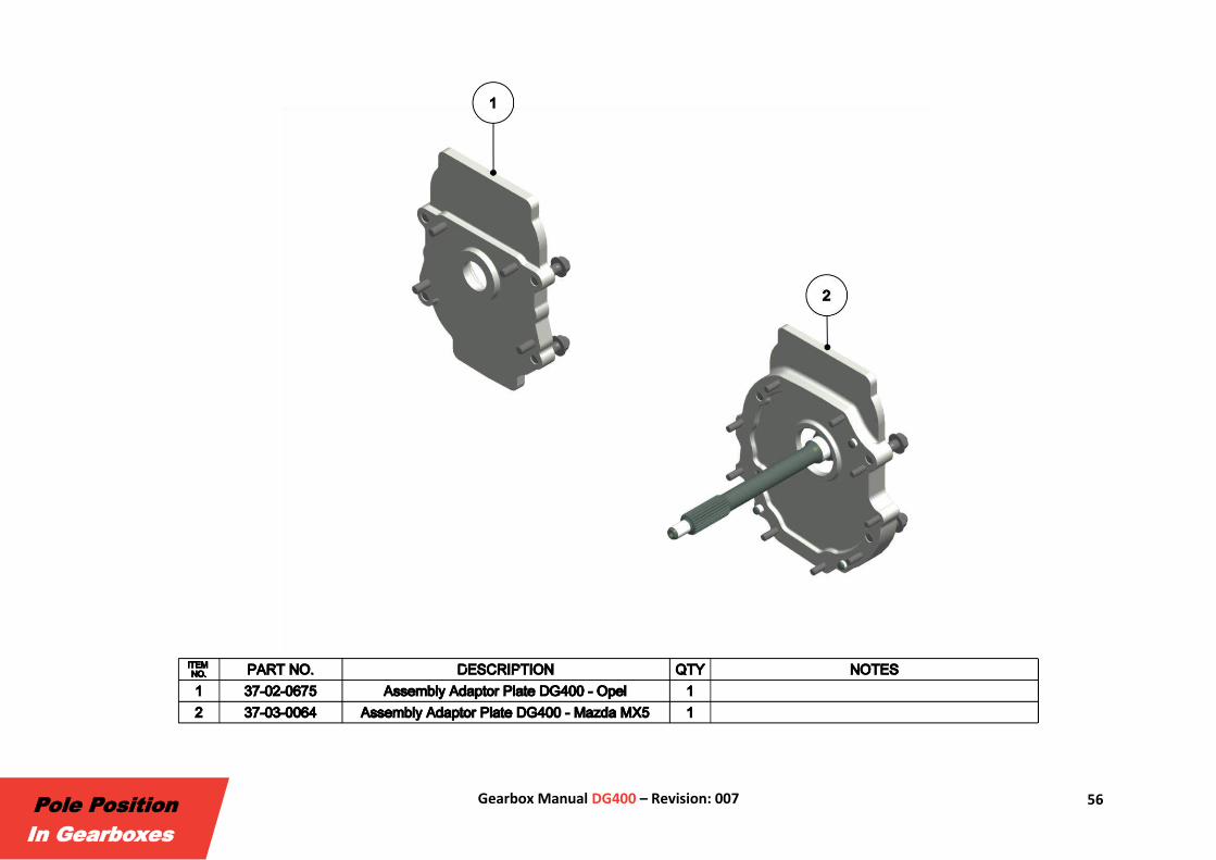
4.1. Bellhousings / Adaptor Plates Drenth Gearboxes offers a variety of removable bellhousings and adaptor plates to mount the DG400 into different vehicles. In addition, bellhousings and
adaptor plates for customer specific applications can be developed, produced and supplied.
55 Gearbox Manual DG400 – Revision: 007
Pole Position
In Gearboxes
56 Gearbox Manual DG400 – Revision: 007
Pole Position
In Gearboxes
57 Gearbox Manual DG400 – Revision: 007
Pole Position
In Gearboxes
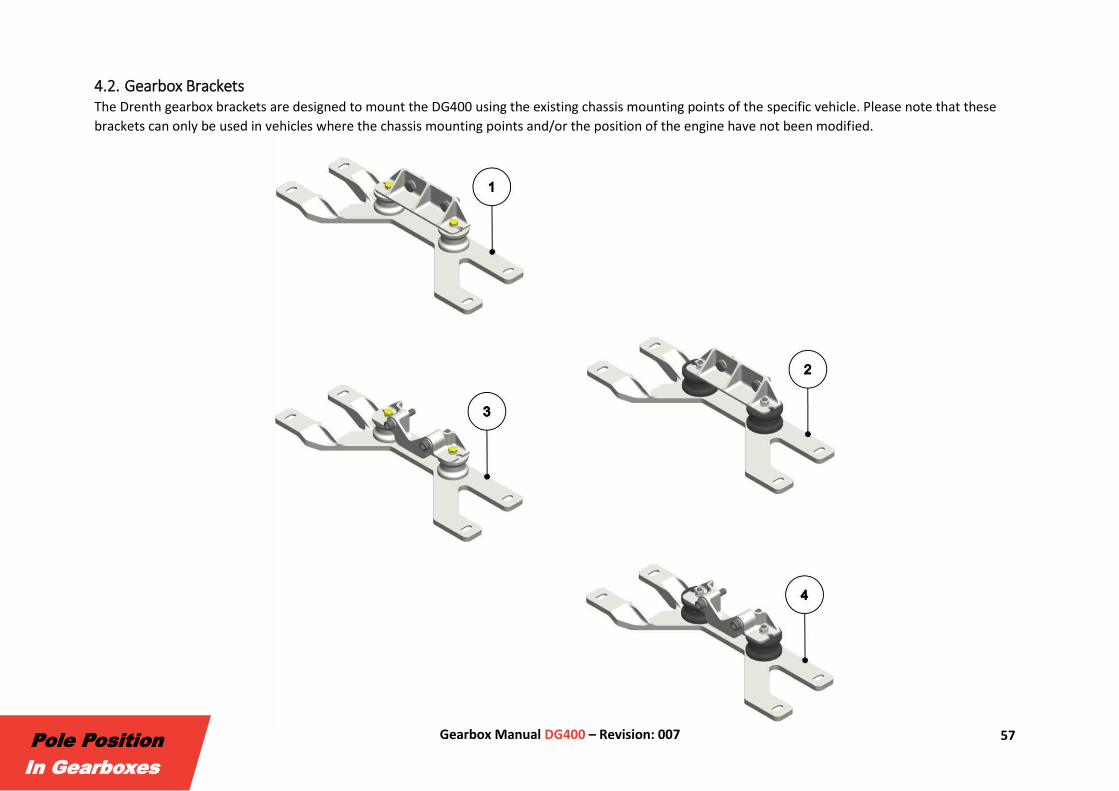
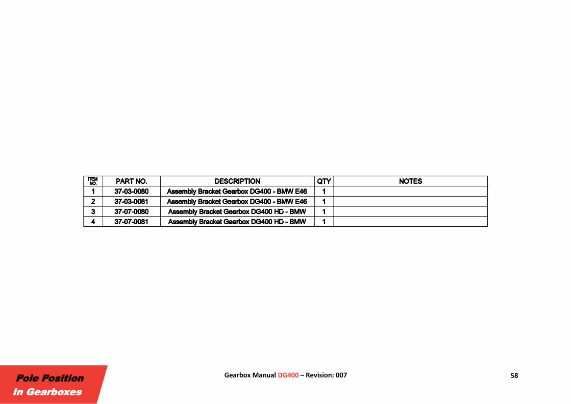
4.2. Gearbox Brackets The Drenth gearbox brackets are designed to mount the DG400 using the existing chassis mounting points of the specific vehicle. Please note that these
brackets can only be used in vehicles where the chassis mounting points and/or the position of the engine have not been modified.
58 Gearbox Manual DG400 – Revision: 007
Pole Position
In Gearboxes
59 Gearbox Manual DG400 – Revision: 007
Pole Position
In Gearboxes
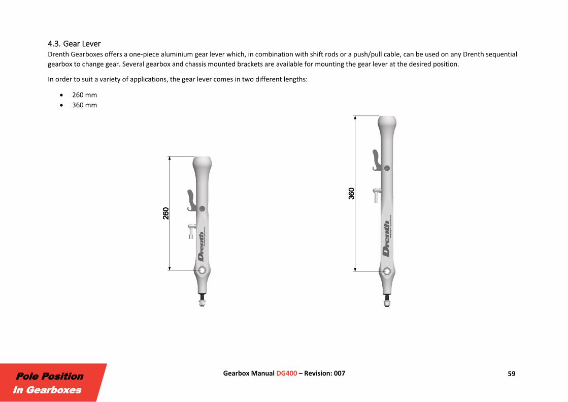
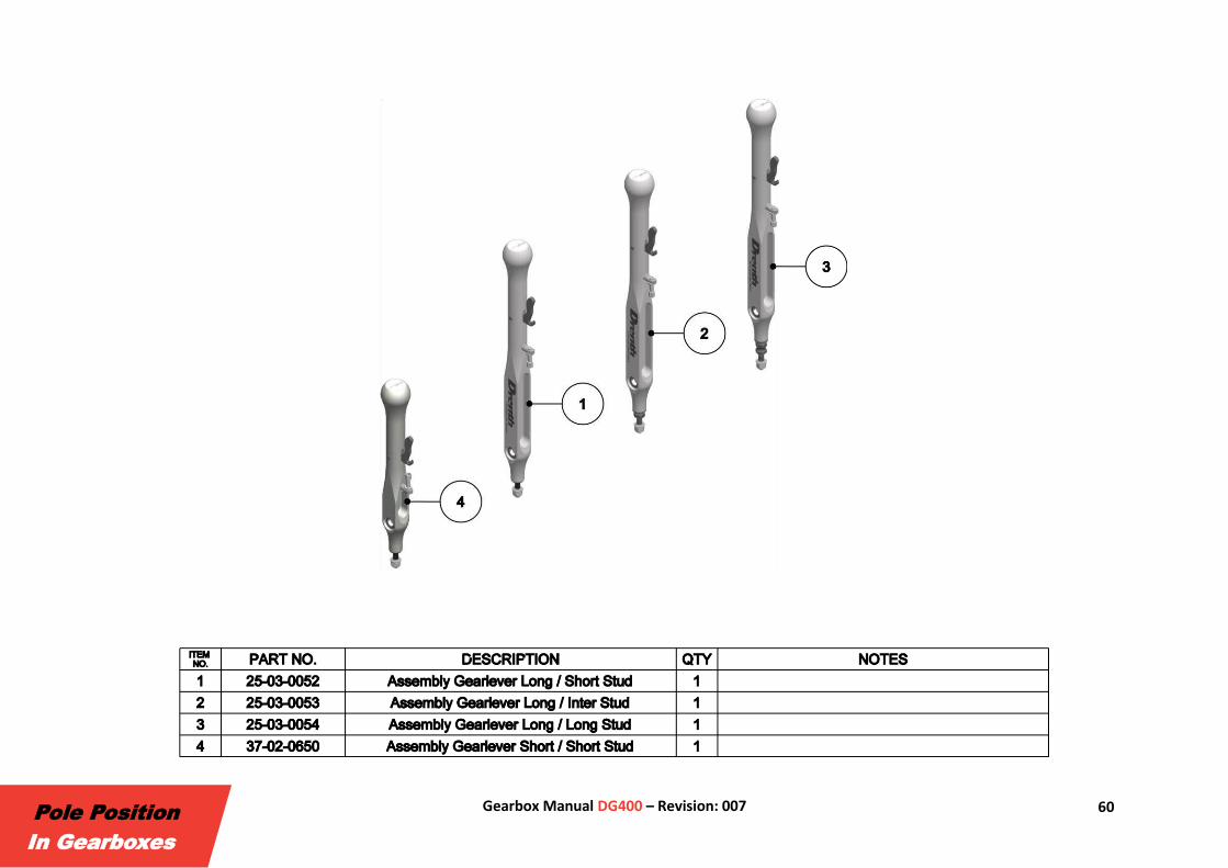
4.3. Gear Lever Drenth Gearboxes offers a one-piece aluminium gear lever which, in combination with shift rods or a push/pull cable, can be used on any Drenth sequential
gearbox to change gear. Several gearbox and chassis mounted brackets are available for mounting the gear lever at the desired position.
In order to suit a variety of applications, the gear lever comes in two different lengths:
• 260 mm • 360 mm
60 Gearbox Manual DG400 – Revision: 007
Pole Position
In Gearboxes
61 Gearbox Manual DG400 – Revision: 007
Pole Position
In Gearboxes
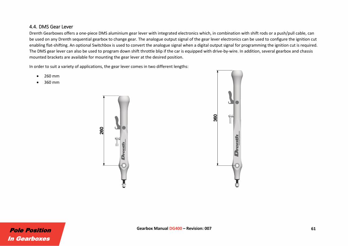
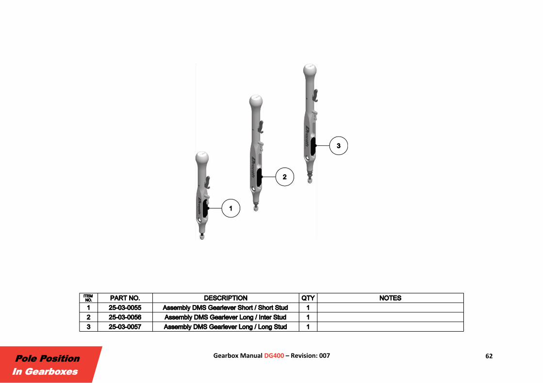
4.4. DMS Gear Lever Drenth Gearboxes offers a one-piece DMS aluminium gear lever with integrated electronics which, in combination with shift rods or a push/pull cable, can
be used on any Drenth sequential gearbox to change gear. The analogue output signal of the gear lever electronics can be used to configure the ignition cut
enabling flat-shifting. An optional Switchbox is used to convert the analogue signal when a digital output signal for programming the ignition cut is required.
The DMS gear lever can also be used to program down shift throttle blip if the car is equipped with drive-by-wire. In addition, several gearbox and chassis
mounted brackets are available for mounting the gear lever at the desired position.
In order to suit a variety of applications, the gear lever comes in two different lengths:
• 260 mm • 360 mm
62 Gearbox Manual DG400 – Revision: 007
Pole Position
In Gearboxes
63 Gearbox Manual DG400 – Revision: 007
Pole Position
In Gearboxes
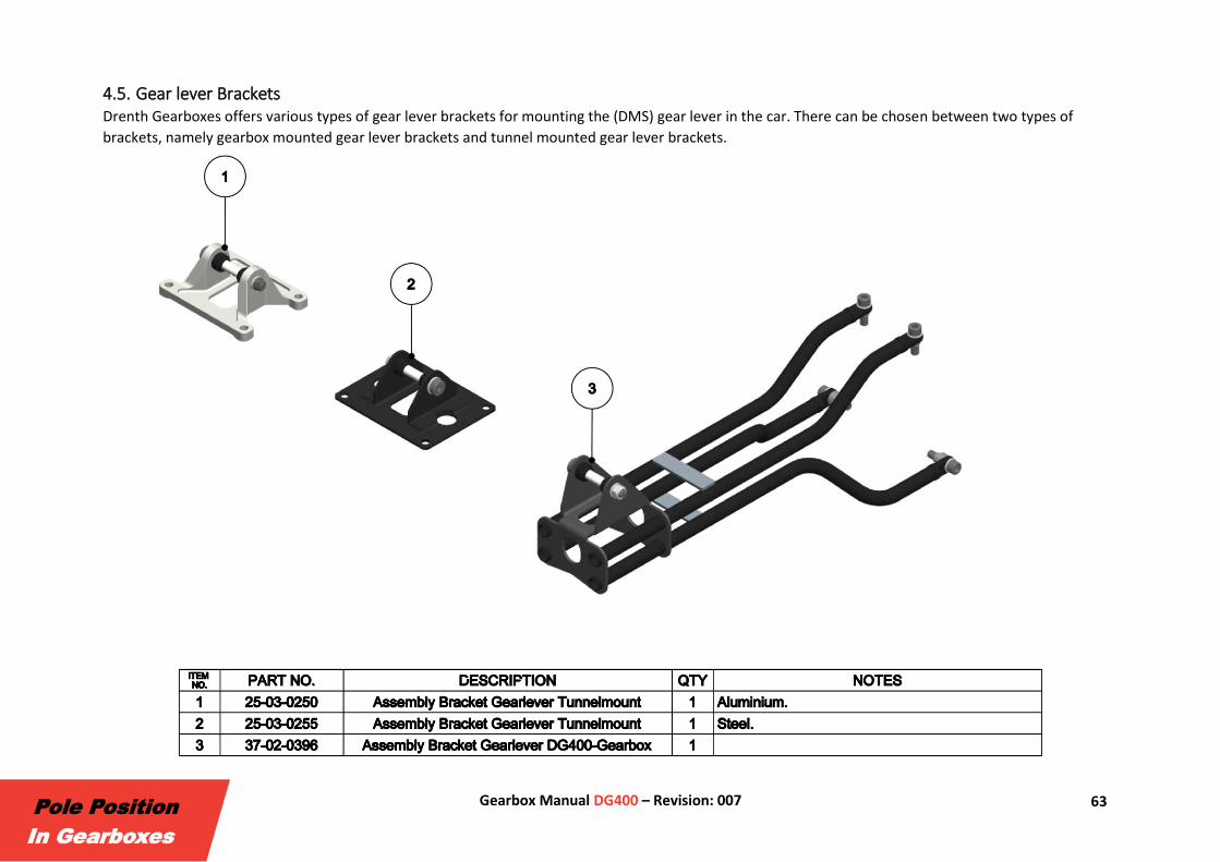
4.5. Gear lever Brackets Drenth Gearboxes offers various types of gear lever brackets for mounting the (DMS) gear lever in the car. There can be chosen between two types of
brackets, namely gearbox mounted gear lever brackets and tunnel mounted gear lever brackets.
64 Gearbox Manual DG400 – Revision: 007
Pole Position
In Gearboxes
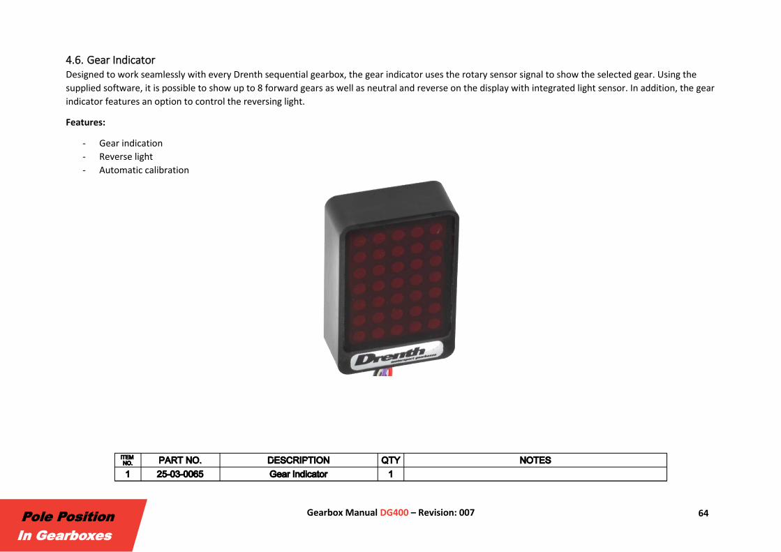
4.6. Gear Indicator Designed to work seamlessly with every Drenth sequential gearbox, the gear indicator uses the rotary sensor signal to show the selected gear. Using the
supplied software, it is possible to show up to 8 forward gears as well as neutral and reverse on the display with integrated light sensor. In addition, the gear
indicator features an option to control the reversing light.
Features:
- Gear indication
- Reverse light
- Automatic calibration
65 Gearbox Manual DG400 – Revision: 007
Pole Position
In Gearboxes
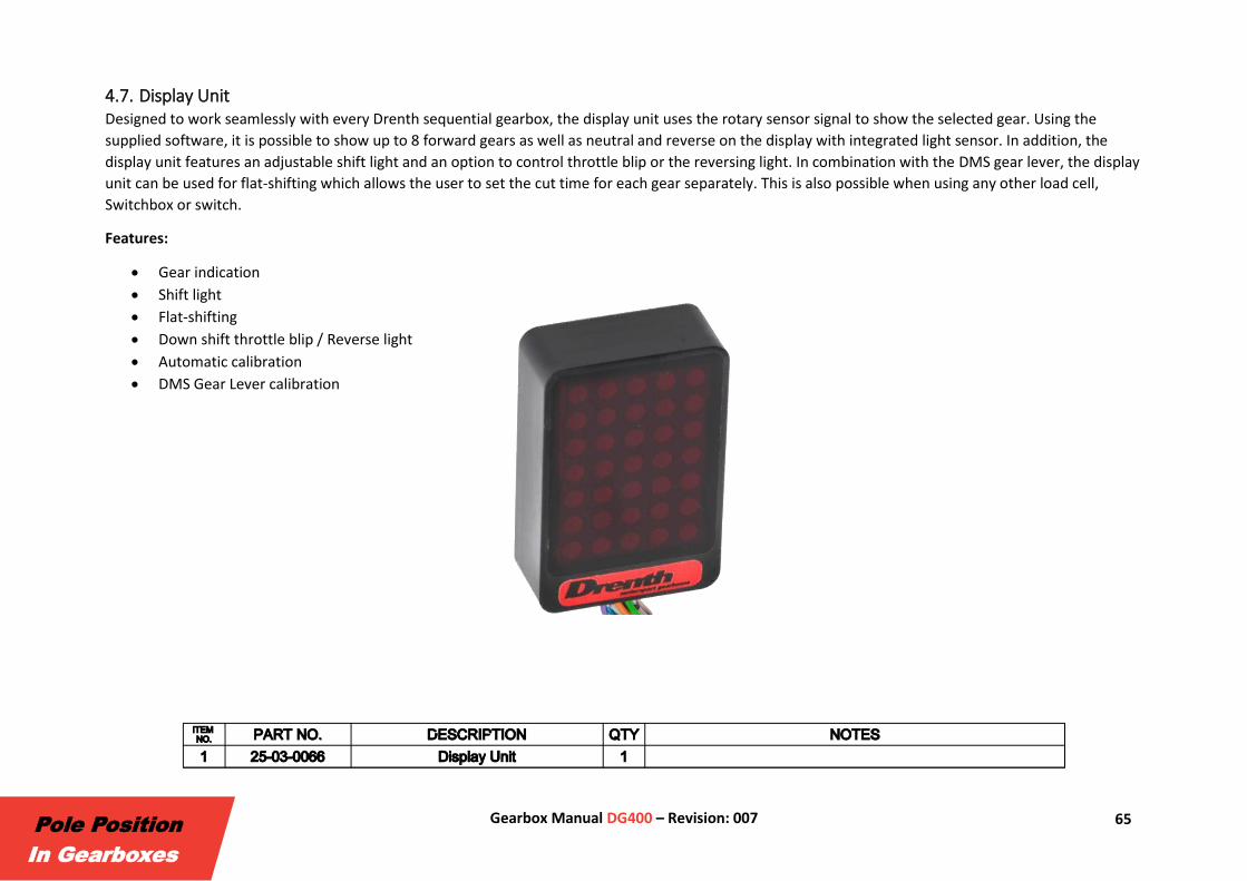
4.7. Display Unit Designed to work seamlessly with every Drenth sequential gearbox, the display unit uses the rotary sensor signal to show the selected gear. Using the
supplied software, it is possible to show up to 8 forward gears as well as neutral and reverse on the display with integrated light sensor. In addition, the
display unit features an adjustable shift light and an option to control throttle blip or the reversing light. In combination with the DMS gear lever, the display
unit can be used for flat-shifting which allows the user to set the cut time for each gear separately. This is also possible when using any other load cell,
Switchbox or switch.
Features:
• Gear indication • Shift light • Flat-shifting • Down shift throttle blip / Reverse light • Automatic calibration • DMS Gear Lever calibration

66 Gearbox Manual DG400 – Revision: 007
Pole Position
In Gearboxes
4.8. Switchbox The Drenth Gearboxes Switchbox is an analog-to-digital converter which is used in combination with the Drenth Display Unit or a programmable ECU to
enable flat-shifting. When a digital output signal is required for setting the ignition cut the Switchbox is used to convert the analogue signal. Because the
Switchbox is equipped with two potentiometers, the upshift and downshift threshold levels can be adjusted as desired.
Features:
• Adjustable downshift threshold voltage
• Adjustable upshift threshold voltage

67 Gearbox Manual DG400 – Revision: 007
Pole Position
In Gearboxes
4.9. Oil Breather Catchtank Drenth Gearboxes recommends the use of an Oil Breather Catch Tank for breathing the gearbox. Therefore Drenth Gearboxes offers a universal catch tank
which can be used with any gearbox. The set includes the breather catch tank, oil hose and the necessary adaptors.

68 Gearbox Manual DG400 – Revision: 007
Pole Position
In Gearboxes
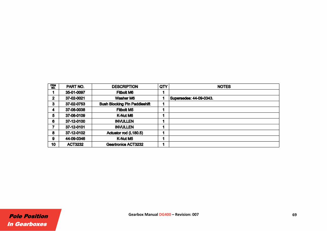
4.10. Paddleshift System The DG400 can be equipped with a paddleshift system allowing the driver to change gears by using steering wheel mounted shift paddles. For mounting the
actuators of the different paddleshift systems, Drenth Gearboxes has developed various brackets for the DG400. If the preferred paddleshift system has a
safety feature which prevent the driver from selecting neutral and reverse accidentally during downshifts, then the mechanical blocking system can be
replaced and / or removed. In this case the following parts are required:
69 Gearbox Manual DG400 – Revision: 007
Pole Position
In Gearboxes

70 Gearbox Manual DG400 – Revision: 007
Pole Position
In Gearboxes
5. Assembly Tooling

71 Gearbox Manual DG400 – Revision: 007
Pole Position
In Gearboxes
Optionally, Drenth Gearboxes provide tools which are used for assembling and disassembling the DG400. The tools listed below make it possible to perform
maintenance on the DG400:
72 Gearbox Manual DG400 – Revision: 007
Pole Position
In Gearboxes
6. Contact Information
73 Gearbox Manual DG400 – Revision: 007
Pole Position
In Gearboxes
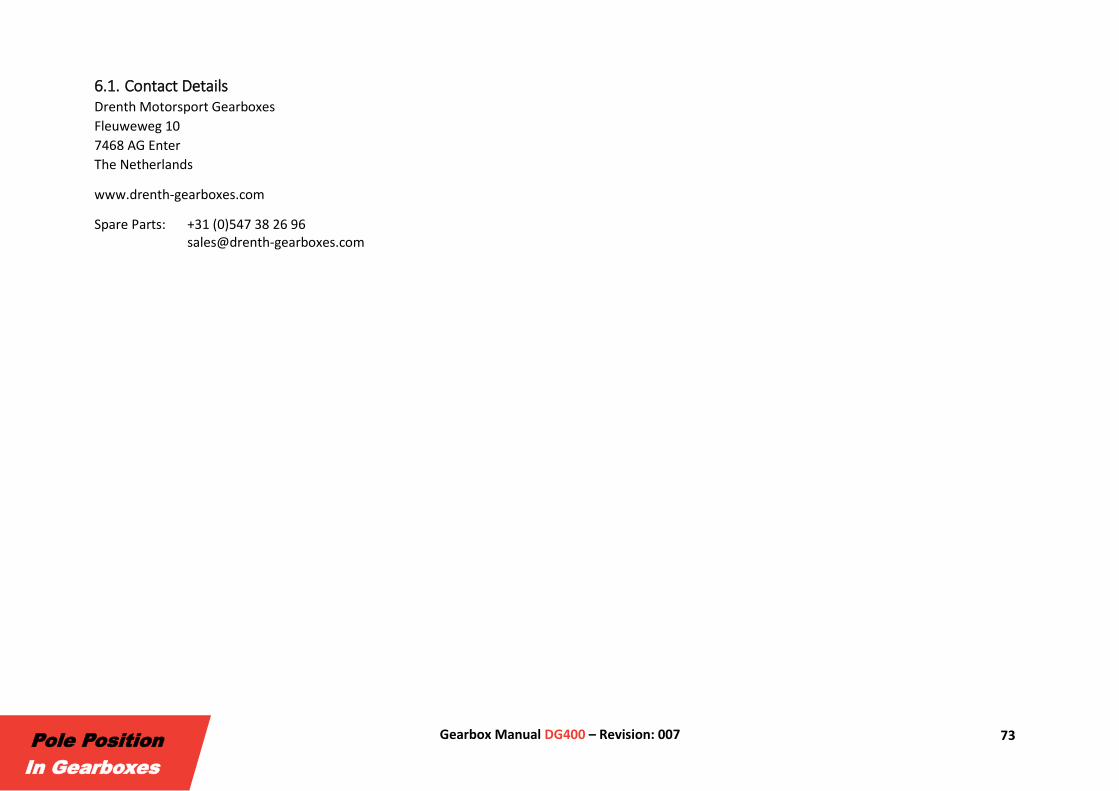
6.1. Contact Details Drenth Motorsport Gearboxes
Fleuweweg 10
7468 AG Enter
The Netherlands
www.drenth-gearboxes.com
Spare Parts: +31 (0)547 38 26 96 [email protected]
74 Gearbox Manual DG400 – Revision: 007
Pole Position
In Gearboxes
Appendix A: Technical Bulletins

75 Gearbox Manual DG400 – Revision: 007
Pole Position
In Gearboxes

76 Gearbox Manual DG400 – Revision: 007
Pole Position
In Gearboxes
Appendix B: Amendments
77 Gearbox Manual DG400 – Revision: 007
Pole Position
In Gearboxes
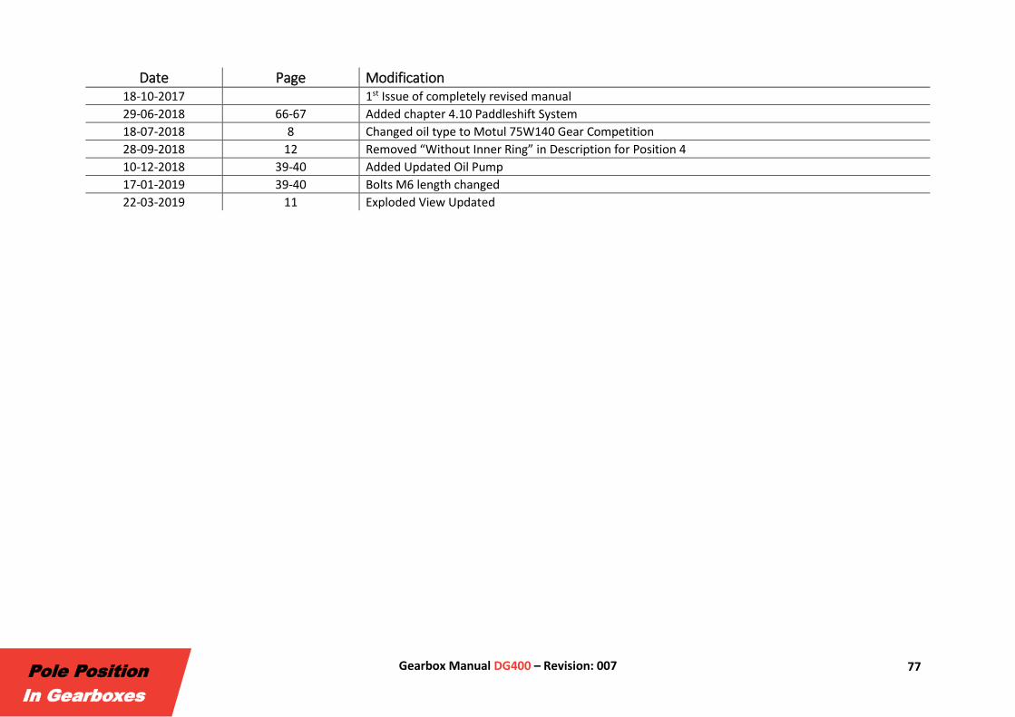
Date Page Modification 18-10-2017 1st Issue of completely revised manual
29-06-2018 66-67 Added chapter 4.10 Paddleshift System
18-07-2018 8 Changed oil type to Motul 75W140 Gear Competition
28-09-2018 12 Removed “Without Inner Ring” in Description for Position 4
10-12-2018 39-40 Added Updated Oil Pump
17-01-2019 39-40 Bolts M6 length changed
22-03-2019 11 Exploded View Updated
T +31 (0)547 38 26 96 E [email protected] W www.drenth-gearboxes.com