gearmo gm-ftdi2x usb to rs-232 converter user manualgearmo.com/files/gm-ftdi2x user manual.pdf ·...
TRANSCRIPT

Model: GM-FTDI2X 2 Port USB to RS-232 Commercial Interface Converter Instruction Manual

Contents
1. Overview 3
2. Main Features 3
3. Hardware Installation and Application 3
4. Performance Parameters 3
5. Connector and Signals 4
6. Product Dimension and Connection Diagram 4
7. Fault and Trouble-Shooting 5
8. Driver Installation Procedure 6-13

Overview
The USB interface is gradually replacing the old-fashioned, low-speed peripheral interfaces with the continuous development of the PC industry. Many vital devices in current industrial environments are still designed using an RS-232 interface, so the USB to RS-232 converters are needed to transfer data between PC and RS-232 devices.
GM-FTDI2X is a universal USB 2 port RS-232 converter which doesn’t need external power supply and is compatible with USB and RS-232 standards. It can convert single-end USB signal to RS-232 signal, and it has built-in automatic transmit-receive switch without time delay. The unique I/O circuit can be used to automatically control the direction of data flow so as to make it plug-and-play and applicable to all existing communication software and interface hardware.
GM-FTDI2X supports point-to-point communication with data rate of 300-921,600bps. The power indicator and data traffic indicator LED’s can be used for fault indication. USB to RS-232 conversion is supported.
Main Features Following communication modes are supported by GM-FTDI2X interface converter:1) Point-to-point communication mode.
Hardware Installation and ApplicationPlease read this manual thoroughly and connect the USB cable to the USB port of the computer BEFORE the installation of GM-FTDI2X interface converter. USB to DB9M connectors are adopted for the input/output terminal and twisted cable or screened cable can be used. RS-232 communication mode can be implemented without any configuration and the connection and disassembly are very convenient. The converter uses 9 wires which are; DCD, RXD, TXD, DTR, GND, DSR, RTS, CTS, and RI with all signal connections.
Performance Parameters
1. Standards: Conforming to USB 1.1, 1.0 and 2.0 standards and EIA RS-232 standard. 2. USB signals: VCC, DATA-, DATA+, GND, FG 3. RS-232 signals: DCD, RXD, TXD, DTR, GND, DSR, RTS, CTS, RI 4. Operating mode: Asynchronous mode, point-to-point mode. 5. Data flow control: Automatic data flow control technique is adopted to automatically determine and control the
data flow. 6. Baud rate: 300-921,600bps, automatically detecting the data rate. 7. Load capacity: point-to-point communication mode is supported. 8. Communication distance: 5 meters for RS-232 interface and no more than 5 meters for the USB port. 9. Interface protection: surge protection, ±15KV ESD protection. 10. Interface connection: A type male connector at USB side and DB9 male connector at RS-232 side. 11. Signal indication: 2 signal indicators transmit (TXD) receive (RXD) 1 power indicator (POWER.) 12. Transmission media: twisted-pair cable or shielded cable. 13. Cable length: 1500mm 14. Working environment: -40°C to 85°C, relative humidity of 5% to 95% 15. Supports Win98, 2000, 2003, 2008, XP, Vista, 7, 8, CE, Mac, Linux.

Connector and Signals
1) Pin assignment of RS-232C DB9M (PIN) RS-232C
1 Protective Earth 2 Receive Data SIN (RXD) 3 Transmit Data SOUT (TXD) 4 Data Terminal Ready (DTR) 5 Signal Ground (GND) 6 Data Set Ready (DSR) 7 Request to Send (RTS) 8 Clear to Send (CTS) 9 Ring Indicator (RI)
2) USB-A type: USB signal input and pin assignment
1. VCC 2. DATA-(DM) 3. DATA+(DP) 4. GND
Product Dimension and Connection Diagram
1. Standard USB A-type male connector 2. Filter magnetic ring 3. Screened black standard USB 2.0 cable 4. Aesthetic shell (black) 5. Standard DB9 male connector 6. Master chip of FTDT company in England
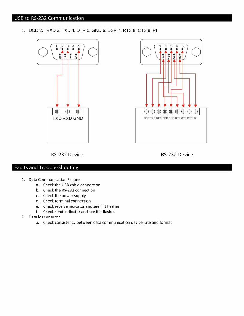
USB to RS-232 Communication
1. DCD 2, RXD 3, TXD 4, DTR 5, GND 6, DSR 7, RTS 8, CTS 9, RI
RS-232 Device
RS-232 Device
Faults and Trouble-Shooting1. Data Communication Failure a. Check the USB cable connection b. Check the RS-232 connection c. Check the power supply d. Check terminal connection e. Check receive indicator and see if it flashes f. Check send indicator and see if it flashes
2. Data loss or error a. Check consistency between data communication device rate and format

Driver Installation Procedure The following dialogue box will pop up automatically when the GM-FTDI2X is connected to PC. Please select install from list or specified location (For advanced user) and click “Next”.
The following dialogue box for path selection will be shown, and please select “Don’t search. I’ll select the driver to be installed by myself” (D) and click “Next”.
Then the hardware type dialogue box will be shown and please scroll to (Universal serial bus controller) and click “Next”.
The dialogue box named “select the driver to be installed for this hardware” will be shown and please click “install from hard disk” (H)

Then the dialogue box named “install form hard disk” will be shown, please click (browse) to select the path of driver.
The dialogue box for “Find files” will pop up, and then select the CD path. Select (USB 2.0 TO Rs232 Cable) and open or just double click it as shown in the following figure.
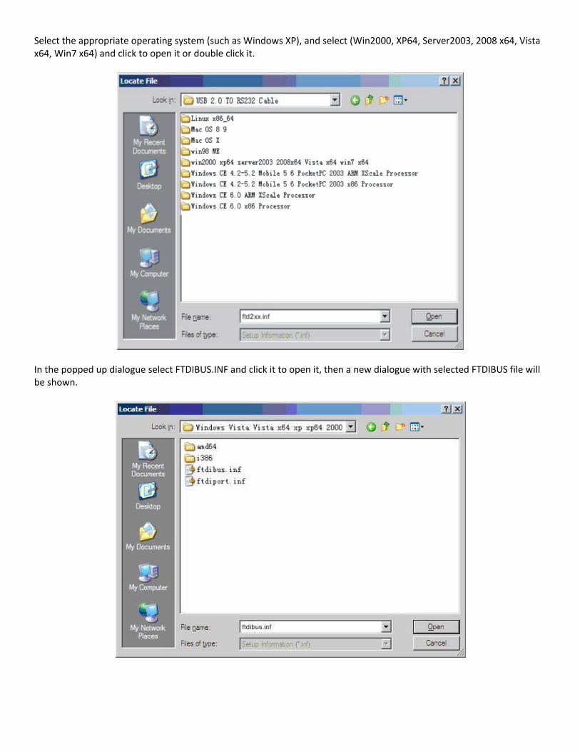
Select the appropriate operating system (such as Windows XP), and select (Win2000, XP64, Server2003, 2008 x64, Vista x64, Win7 x64) and click to open it or double click it.
In the popped up dialogue select FTDIBUS.INF and click it to open it, then a new dialogue with selected FTDIBUS file will be shown.

Below is the driver path and then please click (OK).
The system has found the hardware installation information of the USB Serial Converter as shown in the figure below, then click “Next”.

The USB Serial Converter installation wizard is completed just as shown in the following figure. Then the system will detect the USB Serial Port automatically and show the “New hardware found” wizard.
The following dialogue shows the new hardware wizard of USB Serial Port. Please click “Next” and the following steps are just the same as the wizard of USB Serial Converter, so we won’t describe it in detail here.
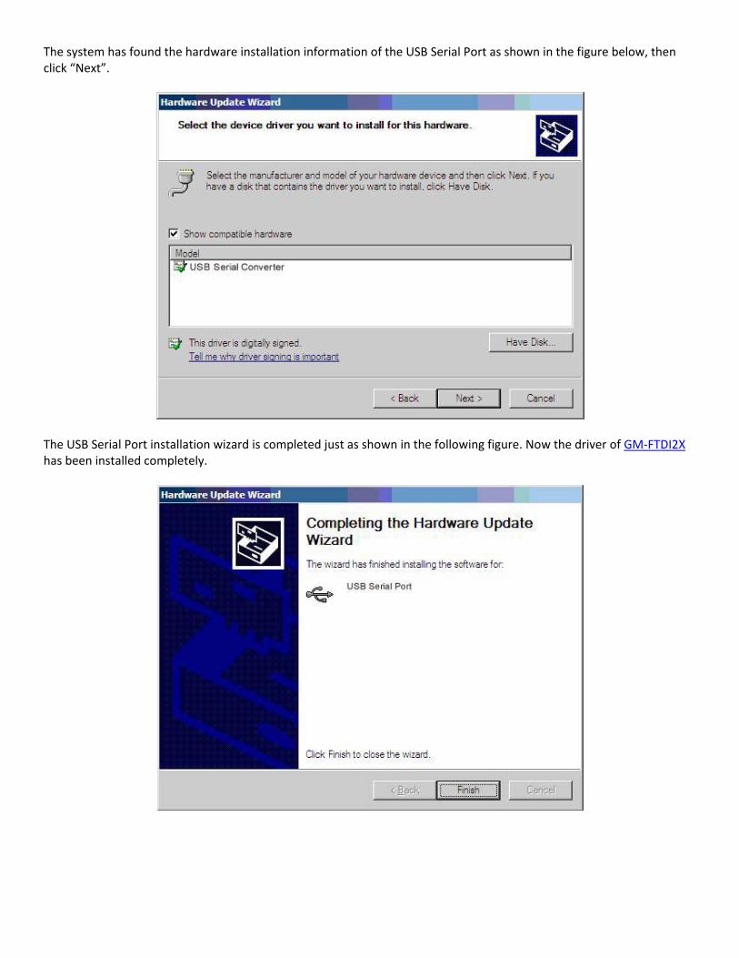
The system has found the hardware installation information of the USB Serial Port as shown in the figure below, then click “Next”.
The USB Serial Port installation wizard is completed just as shown in the following figure. Now the driver of GM-FTDI2X has been installed completely.

After the driver has been installed correctly please have a look at the device manager to make sure whether there is virtual COM port. If it’s the first time to install the USB driver on this system then the default COM ports are COM3 and COM4 as shown in the following figure. Up to now the driver of GM-FTDI2X has been installed successfully.