gears & fuse gears semiconductor fuses...
TRANSCRIPT

Gears & Fuse GearsGears & Fuse Gears
FG228
Semiconductor FusesAC+DC Ferrule Fuse Holders
Clips
12/04
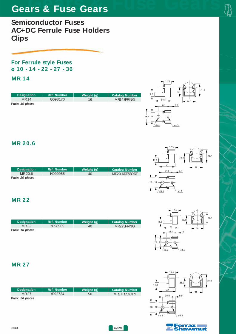
For Ferrule style Fusesø 10 - 14 - 22 - 27 - 36
• SILVER-PLATED COPPER CLIPS: EXTREMELY HIGH THERMALAND ELECTRIC CONDUCTIVITY
• MOUNTING TYPE:- SCREWING ON ISOLATORS- SCREWING ON BARS OR INSULATED BARS- WELDING ON P.C.B. (MR 10 CI)
• STAINLESS STEEL PRESSURE SPRINGS: HIGHLY RESISTANT TOSALT SPRAY
Main Characteristics
MR 10MR 10 CI
MR 14 - MR 20.6
MR 22- MR 27 MR 36
DesignationCurrentratingIN( A )
Recommended copper cable section (mm2)
Maximum R.M.S continuous current throughIN - rated current fuses
( A )MR 10
MR 10 CIMR 14MR 20MR 22MR 27MR 36
323263
125135250250
44
103535
120120
32 32 63
125135250250
Ref. NumberB098004
DesignationMR 10
Catalog NumberMR10RESSORT
Weight (g)7
Ref. NumberY098507
DesignationMR 10 CI
Catalog NumberMR10RESSORTCI
Weight (g)4,5
Ref. NumberC098994
DesignationMR 10 without
connection
Catalog NumberMR10RESSORTSP
Weight (g)5,7
MR 10 - MR 10 CI
10.1
14
15.520.5
ø4.2
9
0.8
Pack: 20 pieces
Pack: 20 pieces
Pack: 200 pieces
Semiconductor FusesAC+DC Ferrule Fuse HoldersClips
FG229
Gears & Fuse GearsGears & Fuse Gears
12/04
For Ferrule style Fusesø 10 - 14 - 22 - 27 - 36
Ref. NumberG098170
DesignationMR 14
Catalog NumberMR14SPRING
Weight (g)16
Ref. NumberH099988
DesignationMR 20.6
Catalog NumberMR20.6RESSORT
Weight (g)40
Ref. NumberK098909
DesignationMR 22
Catalog NumberMR22SPRING
Weight (g)40
Ref. NumberY092734
DesignationMR 27
Catalog NumberMR27RESSORT
Weight (g)50
MR 14
22
34.5
11.5
20.7
21.517
8.3
1618.6
ø6.5 ø4.5
5.5
MR 20.6
24.5
42
17.5
29
29.720.8
11.2
2226
ø6.5 ø4.5
8.5
MR 22
24.5
42
17.5
29
29.720.8
11.2
2226
ø6.5 ø4.5
8.5
MR 27
Pack: 10 pieces
Pack: 20 pieces
Pack: 10 pieces
Pack: 20 pieces

Gears & Fuse GearsGears & Fuse Gears
FG230
Semiconductor FusesAC+DC Ferrule FuseHolders
Clips
For Ferrule style Fusesø 10 - 14 - 22 - 27 - 36
12/04
MR 36
33
56
27.5
42
47.532.5
1.5
26
ø 8.5 ø 6.5
12.5
All clips silver-plated copper with stainless steel springs.
Ref. NumberM091275
DesignationMR 36
Catalog NumberMR36R
Weight (g)85
Mounting InstructionsP.C.B. Drilling for MR10 CI clip (10 X 38 Size Fuse)
Clip Mounting
12.7 12.716 to 17
6.35
2 x 4 holes ø 2
L
A
Fixing in position2 holes ø 2 mm
Alignment
Fuse size10 x 3814 x 5122 x 5820 x 51
20 x 12720 x 19027 x 60
36 x 12736 x 190
A31424236
11317541
100165
L61869185
16222491
148231
Mounting of two elastic stop pins of 2 mm dia. for fixing clips in position
Pack: 1 piece
Gears & Fuse GearsGears & Fuse Gears
FG232
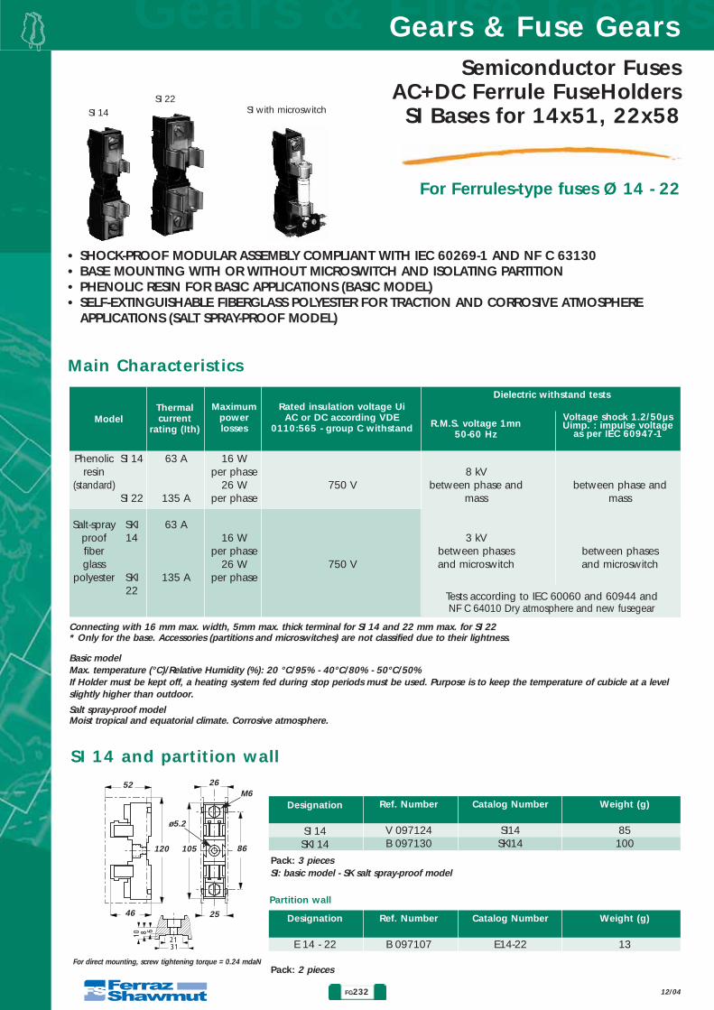
Semiconductor FusesAC+DC Ferrule FuseHoldersSI Bases for 14x51, 22x58
12/04
For Ferrules-type fuses Ø 14 - 22
• SHOCK-PROOF MODULAR ASSEMBLY COMPLIANT WITH IEC 60269-1 AND NF C 63130• BASE MOUNTING WITH OR WITHOUT MICROSWITCH AND ISOLATING PARTITION• PHENOLIC RESIN FOR BASIC APPLICATIONS (BASIC MODEL)• SELF-EXTINGUISHABLE FIBERGLASS POLYESTER FOR TRACTION AND CORROSIVE ATMOSPHERE
APPLICATIONS (SALT SPRAY-PROOF MODEL)
SI 14
SI 22SI with microswitch
Main Characteristics
ModelThermalcurrent
rating (Ith)
Rated insulation voltage UiAC or DC according VDE
0110:565 - group C withstand
Dielectric withstand tests
R.M.S. voltage 1mn50-60 Hz
Voltage shock 1.2/50µsUimp. : impulse voltage
as per IEC 60947-1
Maximumpowerlosses
Connecting with 16 mm max. width, 5mm max. thick terminal for SI 14 and 22 mm max. for SI 22* Only for the base. Accessories (partitions and microswitches) are not classified due to their lightness.
Basic modelMax. temperature (°C)/Relative Humidity (%): 20 °C/95% - 40°C/80% - 50°C/50%If Holder must be kept off, a heating system fed during stop periods must be used. Purpose is to keep the temperature of cubicle at a levelslightly higher than outdoor.
Salt spray-proof modelMoist tropical and equatorial climate. Corrosive atmosphere.
Phenolicresin
(standard)
Salt-sprayprooffiberglass
polyester
63 A
135 A
63 A
135 A
SI 14
SI 22
SKI14
SKI22
16 Wper phase
26 Wper phase
16 Wper phase
26 Wper phase
8 kVbetween phase and
mass
3 kVbetween phasesand microswitch
between phase andmass
between phasesand microswitch
750 V
750 V
Tests according to IEC 60060 and 60944 and NF C 64010 Dry atmosphere and new fusegear
Ref. Number
V 097124B 097130
Designation
SI 14SKI 14
Pack: 3 pieces
Pack: 2 pieces
Weight (g)
85100
Catalog Number
SI14SKI14
SI 14 and partition wall
31
6810
21
SI: basic model - SK salt spray-proof model
52 26M6
2546
120
For direct mounting, screw tightening torque = 0.24 mdaN
105 86
ø5.2
Ref. Number
B 097107
Designation
E 14 - 22
Weight (g)
13
Catalog Number
E14-22
Partition wall
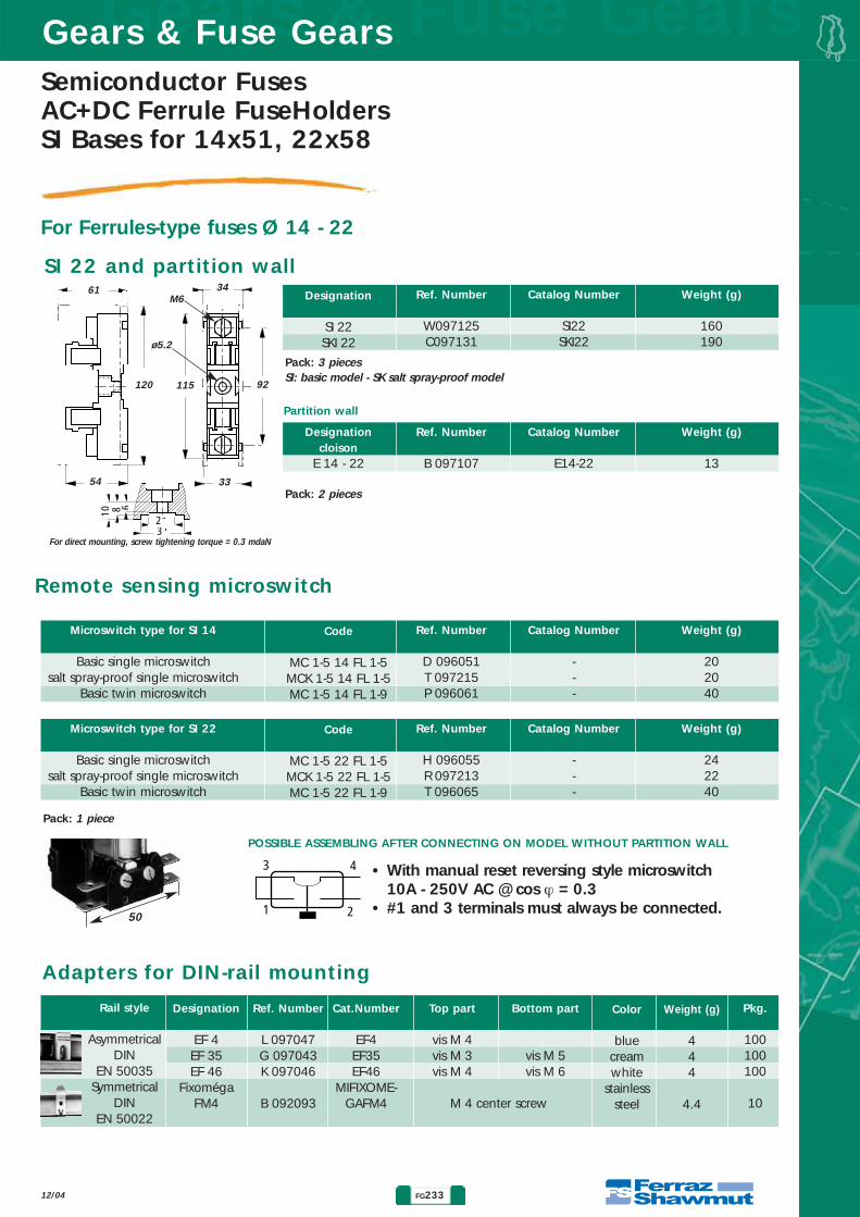
Semiconductor FusesAC+DC Ferrule FuseHoldersSI Bases for 14x51, 22x58
FG233
Gears & Fuse GearsGears & Fuse Gears
12/04
For Ferrules-type fuses Ø 14 - 22
Ref. Number
W097125C097131
Designation
SI 22SKI 22
Pack: 3 pieces
Pack: 2 pieces
Weight (g)
160190
Catalog Number
SI22SKI22
SI: basic model - SK salt spray-proof model
Pack: 1 piece
Ref. Number
B 097107
Designationcloison
E 14 - 22
Weight (g)
13
Catalog Number
E14-22
SI 22 and partition wall
31
6810
21
61
120 115
34M6
3354
For direct mounting, screw tightening torque = 0.3 mdaN
92
ø5.2
Ref. Number
L 097047G 097043K 097046
B 092093
Cat.Number
EF4EF35EF46
MIFIXOME-GAFM4
Top part
vis M 4vis M 3vis M 4
Bottom part
vis M 5vis M 6
Designation
EF 4EF 35EF 46
FixomégaFM4
Rail style
AsymmetricalDIN
EN 50035Symmetrical
DINEN 50022
Pkg.
100100100
10
Weight (g)
444
4.4
Color
bluecreamwhite
stainlesssteelM 4 center screw
Remote sensing microswitch
3
1
4
2
• With manual reset reversing style microswitch 10A - 250V AC @ cos ϕ = 0.3
• #1 and 3 terminals must always be connected.50
Adapters for DIN-rail mounting
POSSIBLE ASSEMBLING AFTER CONNECTING ON MODEL WITHOUT PARTITION WALL
Ref. Number
D 096051T 097215P 096061
Code
MC 1-5 14 FL 1-5MCK 1-5 14 FL 1-5MC 1-5 14 FL 1-9
Weight (g)
202040
Catalog Number
---
Microswitch type for SI 14
Basic single microswitchsalt spray-proof single microswitch
Basic twin microswitch
Ref. Number
H 096055R 097213T 096065
Code
MC 1-5 22 FL 1-5MCK 1-5 22 FL 1-5MC 1-5 22 FL 1-9
Weight (g)
242240
Catalog Number
---
Microswitch type for SI 22
Basic single microswitchsalt spray-proof single microswitch
Basic twin microswitch
Partition wall

Gears & Fuse GearsGears & Fuse Gears
FG234
Semiconductor FusesAC+DC Ferrule FuseHolders
MSC10, USM
12/04
MSC 10 Fuse Holder
Nb. of Model without blown fuse Model with blown fuse Poles indicator light indicator light
Ref.number Cat. Number Ref. Number Cat. Number Nb Mod PckgN Q218215 MSC8/10N 1 121 Q216674 MSC101 W219784 MSC101I 1 12
1+N C212085 MSC101N D232602 MSC101NI 2 62 E213122 MSC102 K215151 MSC102I 2 63 M215659 MSC103 R226611 MSC103I 3 4
3+N E217193 MSC103N E232603 MSC103NI 4 34 F218735 MSC104 4 3
for 10x38 fuses without striker, with or without indicator light
MSC 10 fuse holder – no accessoriesIth max. 32A - Un 690V
MSC 10 fuse holder Phase + Neutral (1 mod.)Ith max. 32A - Un 690V
59
78
45
12,5
42,5
5
17,5
78
2,5
35
52,5
70
•Direct mounting on symmetricalDIN rail
• Indicator light (120/690V)• Wiring cross sections:
- single-pole: 1 x 16mm2- single-pole + neutral: 1 x 10 mm2
•Insulated to IP 20 standard
•Single-pole weight- 10x38 ; 63 g- 10x38 - Ph + N1M ; 68 g
Dimensions
Nb. of Model without blown fuse Model with blown fuse Poles indicator light indicator light
Ref.number Cat. Number Ref. Number Cat. Number Nb Mod Pckg1+N Y201317 MSC101N1M C211050 MSC101N1MI 1 123+N S218217 MSC103N3M S226612 MSC103N3MI 3 4
Assembly accessories Ref. Numbrer Cat. Numbrer Pckg2-pole pin G215125 MSC810PAK2 10*3-pole pin Q216145 MSC810PAK3 10*4-pole pin A217166 MSC810PCK4 10*
* 10 per bag
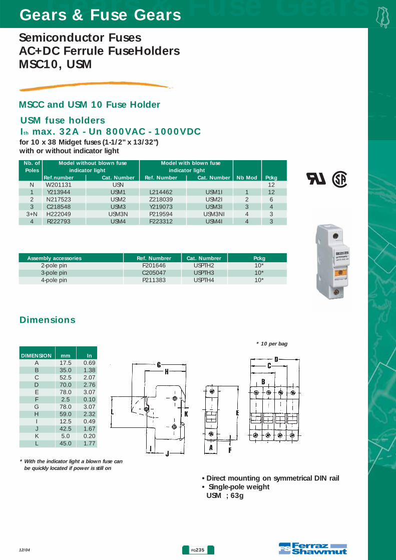
Semiconductor FusesAC+DC Ferrule FuseHoldersMSC10, USM
FG235
Gears & Fuse GearsGears & Fuse Gears
12/04
MSCC and USM 10 Fuse Holder
for 10 x 38 Midget fuses (1-1/2" x 13/32")with or without indicator light
USM fuse holdersIth max. 32A - Un 800VAC - 1000VDC
Dimensions
Nb. of Model without blown fuse Model with blown fuse Poles indicator light indicator light
Ref.number Cat. Number Ref. Number Cat. Number Nb Mod PckgN W201131 USN 121 Y213944 USM1 L214462 USM1I 1 122 N217523 USM2 Z218039 USM2I 2 63 C218548 USM3 Y219073 USM3I 3 4
3+N H222049 USM3N P219594 USM3NI 4 34 R222793 USM4 F223312 USM4I 4 3
Assembly accessories Ref. Numbrer Cat. Numbrer Pckg2-pole pin F201646 USPTH2 10*3-pole pin C205047 USPTH3 10*4-pole pin P211383 USPTH4 10*
* 10 per bag
DIMENSION mm InA 17.5 0.69B 35.0 1.38C 52.5 2.07D 70.0 2.76E 78.0 3.07F 2.5 0.10G 78.0 3.07H 59.0 2.32I 12.5 0.49J 42.5 1.67K 5.0 0.20L 45.0 1.77
•Direct mounting on symmetrical DIN rail• Single-pole weight
USM ; 63g
� �
* With the indicator light a blown fuse canbe quickly located if power is still on

Gears & Fuse GearsGears & Fuse Gears
FG236 12/04
MODULOSTAR® Series
• Impulse withstand voltages : - The range is tested at respectivly Uimp= 6KV and 8KV according to part 8.3.3.4.1 of IEC
60947-1 between neighboring poles, between phase and wires, between phase and microswitch.Insulation voltage rating Ui = 690VAC and 800VAC
- The blown fuse light indicators are available for 24VDC to 700VDC and 110VAC to 690-700VAC• European RoHS Directive:
Modulostar® product range is develop in accordance with European Directive 2002/95/CE dated 27 January 2003, as free of halogene (PBB, PBDE), chlorine, mercury, cadmium and lead.
• Environmental aspectsModulostar® range is design following "ecoconception" method, with sofware tool EIME(Environmental Information & Management Explorer), which takes into account the following criteria: Water Toxicity, Water Eutrophication, Hazardous Waste Production, Raw Material Depletion,Energy Depletion, Water Depletion, Global Warming, Air Toxicity, Photochemical Ozone Creation, AirAcidification
• Plastic material used are UL 94 V0 to V2 with UL Recognized Yellow card RTI ( Relative Thermal Index) > 120°CCTI ( Comparative Tracking Index) > 350VBodies are in Polyamide 6 with 20% reinforced materialHandles are in Polyamide 6.6 with 25% reinforced material or in Thermodur BMC
• Homologations: CB report according IEC 60269-2 and IEC 60947-3 standards UL CSA Listed (600V AC) for class CC products ranges, UL CSA recognition ( 800V AC - 1000V DC)for Midget and IEC products
• Vibration withstand: Tests with sine vibrations carried out at ambiant temperature with scanning each of the three mainaxis of the holder .
Spectrum: 1st segment ( 2 to 16Hz) constant displacement x=5mm peak2nd segment (16 to 250 Hz) constant acceleration γ= 5g peak
Exponential scanning speed: 1 octave per minute.Duration : 2 hours per axis.
• Climatic usage conditions: Modulostar® is designed for temperate climates . For more severe climateswe recommend the following:
General charateristics
The brand-new innovative and comprehensive "MODULOSTAR®" range of Ferraz Shawmut Modular
Fuseholders and Fuse disconnectors is global and designedto accommodate a multitude of fuses from around the
world, including - IEC industrial Cylindrical (gG, aM, gD) -UL class CC, Midget - Special protection class (UR, gR, gD) in
5 sizes : 8x32, 10x38, 14x51, 22x58 and 27x60 mm. All MODULOSTAR® products are manufactured in
accordance with IEC 60269-2, IEC 60947 - 1 & 3, UL512and CSA 22-2 Standards.
Semiconductor FusesAC+DC Ferrule FuseHolders
MODULOSTAR® Highlights
Maximum temperature 20°C 30°C 40°C 50°CMaximum relative humidity 95% 90% 80% 50%Curent derating 1 0.95 0.9 0.8
FG237
Gears & Fuse GearsGears & Fuse Gears
12/04
Semiconductor FusesAC+DC Ferrule FuseHoldersMODULOSTAR® Highlights
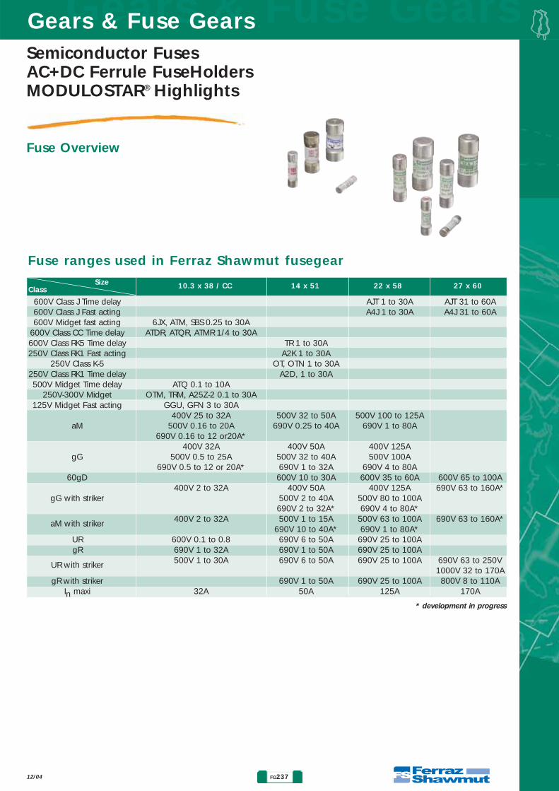
Fuse Overview
Fuse ranges used in Ferraz Shawmut fusegear
* development in progress
Size 10.3 x 38 / CC 14 x 51 22 x 58 27 x 60Class
600V Class J Time delay AJT 1 to 30A AJT 31 to 60A600V Class J Fast acting A4J 1 to 30A A4J 31 to 60A600V Midget fast acting 6JX, ATM, SBS 0.25 to 30A
600V Class CC Time delay ATDR, ATQR, ATMR 1/4 to 30A600V Class RK5 Time delay TR 1 to 30A250V Class RK1 Fast acting A2K 1 to 30A
250V Class K-5 OT, OTN 1 to 30A250V Class RK1 Time delay A2D, 1 to 30A500V Midget Time delay ATQ 0.1 to 10A
250V-300V Midget OTM, TRM, A25Z-2 0.1 to 30A125V Midget Fast acting GGU, GFN 3 to 30A
400V 25 to 32A 500V 32 to 50A 500V 100 to 125AaM 500V 0.16 to 20A 690V 0.25 to 40A 690V 1 to 80A
690V 0.16 to 12 or20A*400V 32A 400V 50A 400V 125A
gG 500V 0.5 to 25A 500V 32 to 40A 500V 100A690V 0.5 to 12 or 20A* 690V 1 to 32A 690V 4 to 80A
60gD 600V 10 to 30A 600V 35 to 60A 600V 65 to 100A400V 2 to 32A 400V 50A 400V 125A 690V 63 to 160A*
gG with striker 500V 2 to 40A 500V 80 to 100A690V 2 to 32A* 690V 4 to 80A*
aM with striker 400V 2 to 32A 500V 1 to 15A 500V 63 to 100A 690V 63 to 160A*690V 10 to 40A* 690V 1 to 80A*
UR 600V 0.1 to 0.8 690V 6 to 50A 690V 25 to 100AgR 690V 1 to 32A 690V 1 to 50A 690V 25 to 100A
UR with striker 500V 1 to 30A 690V 6 to 50A 690V 25 to 100A 690V 63 to 250V 1000V 32 to 170A
gR with striker 690V 1 to 50A 690V 25 to 100A 800V 8 to 110AIn maxi 32A 50A 125A 170A

Gears & Fuse GearsGears & Fuse Gears
FG238 12/04
Semiconductor FusesAC+DC Ferrule FuseHolders
MODULOSTAR® CMS10, US10
IEC fuse holders: CMS10
Accessories
690 V ACAC20B
6 kV 32 A 3 W
≤121620253032
≤12162025
32
≤12162025
32
≤121619222526
2.52.52.5466
NominalVoltage
Ui AC/DC
VoltageIsolation
Uimp
NominalCurrent
Fuse linksrating
Max.power
losses in the fuselinks
Cable wiresection (mm2)recommanded
gG aM URD / gRB
≤1216202530
6JX
* Datas for ambiante temperature = 20°C.
Wire range : Rigid wire = 1- 16 mm2 (18 - 6 AWG) Multistrand wire = 0,75 - 10 mm2 (18 - 8 AWG)Ferraz Shawmut recommands to use screwdrivers PZ 2 or Flat 5.5 x 1 mm (maximum diameter 6 mm)Maximum Tightening Torque : 2.5 Nm (22lb-in)IR for fuses : 120KA @ 500V - 80KA @ 690V
Kit for Multi-Phase connection linksLock
Tag and lockoutjumping bars 1 phase size 8/10 *jumping bars 2 phases size 8/10 *jumping bars 3 phases size 8/10 *jumping bars 4 phases size 8/10 *
1 phase lateral incoming power supply 2 & 3 phases lateral incoming power supply
1 phase axial incoming power supply2 & 3 phases axial incoming power supply
CMS810PAKLOCK
TAGLOCKCMS810CMS810BB1F13CMS810BB2F6CMS810BB3F4CMS810BB4F3
TBB1CTBB23CTBB1A
TBB23A
Z233725M223525A235773T210306V210307W210308X210309E210316G210318D210315F210317
13643
1211
1010101050505050
Description Nb of Mod.(17.5 mm)
6363
10010090909090
Maxi. RMScurrent (A)
1234
Number ofpoles
Catalog Number Pckgreferences
Number
Maxi RMS* Current for 1,2, 3 and 3+N poles with FSfuse links For 4, 5 and 6 poles x by 0.9
For 7, 8, 9 poles x 0.8 For ≥ 10 poles x by 0,7
Electrical characteristics
1122344
CMS810NCMS101
CMS101NCMS102CMS103
CMS103NCMS104
D305006T305020V305021W305022X305023Y305024Z305025
MODULOSTAR® CMS8/10 NEUTREMODULOSTAR® CMS10 1P
MODULOSTAR® CMS10 1P+N MODULOSTAR® CMS10 2P MODULOSTAR® CMS10 3P
MODULOSTAR® CMS10 3P+N MODULOSTAR® CMS10 4P
1122344
121266433
Nb ofPole
Nb ofMod.
(17.5 mm)
MODULOSTAR® Fuse holder without fuse light melting indicator Pckgbox ofCatalog
Number Ref Number Description
122344
CMS101ICMS101NICMS102ICMS103I
CMS103NICMS104
A305026B305027C305028D305029E305030F305031
MODULOSTAR® CMS10 1P C/I MODULOSTAR® CMS10 1P+N C/I MODULOSTAR® CMS10 2P C/I MODULOSTAR® CMS10 3P C/I
MODULOSTAR® CMS10 3P+N C/I MODULOSTAR® CMS10 4P C/I
122344
1266433
Nb ofPole
Nb ofMod.
(17.5 mm)
MODULOSTAR® Fuse holder with fuse light melting indicator Pckgbox ofCatalog
NumberRef
Number Description
MODULOSTAR® Fuse holdersfor 10 x 38 fuse links
Note *: It is possible to use a rigid cable 16 mm2 with a jumping bar 1.5 mm thick.

FG239
Gears & Fuse GearsGears & Fuse Gears
12/04
Semiconductor FusesAC+DC Ferrule FuseHoldersMODULOSTAR® CMS10, US10
IEC fuse holders: US10
Accessories
690V ACAC20B
6 kV 30 A 3 W
≤1620253032
16202530
16202530
16202530
2.52.5466
NominalVoltage
Ui AC/DC
VoltageIsolation
Uimp
NominalCurrent
Fuse linksrating
Max.power
losses in the fuselinks
Cable wiresection (mm2)recommanded
6JX ATM, SBS,GNF, GGU
ATQ, OTM,TMR
1619222526
URD / gRB
Note: UL recognized Voltage are 800V AC and 1000V DC* Datas for ambiante temperature = 20°C.
Wire range : Rigid wire = 1- 16 mm2 (18 - 6 AWG) Multistrand wire = 0,75 - 10 mm2 (18 - 8 AWG)Ferraz Shawmut recommands to use screwdrivers PZ 2 or Flat 5.5 x 1 mm (maximum diameter 6 mm)Maximum Tightening Torque : 2.5 Nm (22lb-in)IR for fuses : 120KA @ 500V IEC - 80KA @ 690V IEC - 80 KA @ 700V UL
Kit for Multi-Phase connection linksLock
Tag and lockoutjumping bars 1 phase size 8/10 *jumping bars 2 phases size 8/10 *jumping bars 3 phases size 8/10 *jumping bars 4 phases size 8/10 *
1 phase lateral incoming power supply 2 & 3 phases lateral incoming power supply
1 phase axial incoming power supply2 & 3 phases axial incoming power supply
US810PAKLOCK
TAGLOCKUS810US810BB1F13US810BB2F6US810BB3F4US810BB4F3
TBB1CTBB23CTBB1A
TBB23A
Z233725M223525A235773T210306V210307W210308X210309E210316G210318D210315F210317
13643
1211
1010101050505050
Description Nb of Mod.(17.5 mm)
6363
10010090909090
Maxi. RMScurrent (A)
1234
Number ofpoles
Catalog Number Pckgreferences
Number
Maxi RMS* Current for 1,2, 3 and 3+N poles with FSfuse links For 4, 5 and 6 poles x by 0.9
For 7, 8, 9 poles x 0.8 For ≥ 10 poles x by 0,7
Electrical characteristics
1122344
US10NUS101
US101NUS102US103
US103NUS104
H305056B305050C305051D305052E305053F305054G305055
MODULOSTAR® US10 NEUTRE �MODULOSTAR® US10 1P �
MODULOSTAR® US10 1P+N �MODULOSTAR® US10 2P �MODULOSTAR® US10 3P �
MODULOSTAR® US10 3P+N �MODULOSTAR® US10 4P �
1122344
121266433
Nb ofPole
Nb ofMod.
(17.5 mm)
MODULOSTAR® Fuse holder without fuse light melting indicator Pckgbox ofCatalog
Number Ref Number Description
122344
US101IUS101NIUS102IUS103I
US103NIUS104I
J305057K305058L305059M305060N305061P305062
MODULOSTAR® US10 1P C/I �MODULOSTAR® US10 1P+N C/I �MODULOSTAR® US10 2P C/I �MODULOSTAR® US10 3P C/I �
MODULOSTAR® US10 3P+N C/I �MODULOSTAR® US10 4P C/I �
122344
1266433
Nb ofPole
Nb ofMod.
(17.5 mm)
MODULOSTAR® Fuse holder with fuse light melting indicator Pckgbox ofCatalog
Number Ref Number Description
MODULOSTAR® Fuse holders � � for Midget and 10 x 38 fuse links
Note *: It is possible to use a rigid cable 16 mm2 with a jumping bar 1.5 mm thick.

Gears & Fuse GearsGears & Fuse Gears
FG240 12/04
Semiconductor FusesAC+DC Ferrule FuseHolders
MODULOSTAR® CMS10, US10
CMS8 & 10, US10, USCC
Accessories
Kit for Multi-Phase connection linksLock
Tag and lockoutjumping bars 1 phase size 8/10 *jumping bars 2 phases size 8/10 *jumping bars 3 phases size 8/10 *jumping bars 4 phases size 8/10 *
1 phase lateral incoming power supply2 & 3 phases lateral incoming power supply
1 phase axial incoming power supply2 & 3 phases axial incoming power supply
CMS810PAKLOCK
TAGLOCKCMS810CMS810BB1F13CMS810BB2F6CMS810BB3F4CMS810BB4F3
TBB1CTBB23CTBB1A
TBB23A
Z233725M223525A235773T210306V210307W210308X210309E210316G210318D210315F210317
13643
1211
1010101050505050
Description Nb of Mod.(17.5 mm)
6363
10010090909090
Maxi. RMScurrent (A)
1234
Number ofpoles
Catalog Number Pckgreferences
Number
Note *: It is possible to use a rigid cable 16 mm2 with a jumping bar 1.5 mm thick.
Dimensions

FG241
Gears & Fuse GearsGears & Fuse Gears
12/04
Semiconductor FusesAC+DC Ferrule FuseHoldersMODULOSTAR® USFM10 - ULTRASAFETM USFMM
Three poles fuse holders and fuse disconnectors: USFM10 / USFMM
Accessories
690 V IEC600V ULAC20B
6 kV 32 A 3 W
≤121620253032
≤1216202530
≤12162025
32
≤121620252627
2.52.52.5466
NominalVoltage
Ui AC/DC
VoltageIsolation
Uimp
NominalCurrent
Fuse linksrating
Max.power
losses in the fuselinks
Cable wiresection (mm2)recommanded
6JX ATM, SBS,GNF, GGU
ATQ, OTM,TMR
≤121619222526
URD / gRB
* Datas for ambiante temperature = 20°C. Wire range : Rigid and Multistrand wire = 1- 4 mm2 (18 - 10 AWG) - Multistrand wire 6 mm2 (9 AWG) with strand repartition between each part of the screw -Maximum multistrand wire for each open lug = 2.6 mm2 (12 AWG)Maximum Tightening Torque : 1.5 Nm (13 lb-in)Ferraz Shawmut recommands to use screwdrivers PZ 2 or Flat 5.5 x 0.8 mm (maximum diameter 6 mm)IR with fuses : 120KA @ 500V IEC - 80KA @ 690V IEC - 80 KA @ 700V UL
LockMicroswitch
Additional Neutraljumping bars 3 phases
Lateral incoming power supply Axial incoming power supply
Interconnexion with SEI 30A ContactorInterconnexion with Rockwell 30A ContactorInterconnexion with SIEMENS 30A Contactor
Interconnexion with ABB 30A ContactorInterconnexion with GE 30A Contactor
LOCKUSFMAC11
TBB23CTBB23A
M223525C302797
G210318F210317
114
11111
11
5050
Description Number of systemsinterconnected
9090
Maxi. RMScurrent (A)
3
3
33333
Number ofpoles
Catalog Number Pckgreferences
Number
Maxi RMS* Current for 1 Three poles system with FS fuse links. For 2 to 7 Three poles systems x by 0.9
Electrical characteristics
3 polessystem / 45 mmwidth
USFM10USFM10MUSFM10I
USFM10MI
S302765T302766W302768 V302767
USFM10 FUSE HOL 3P 690V 32A EU USFM10M FUSEHOL+MC3P690V32A EU
USFM10I FUS.HOL3P+V 690V32A EU USFM10MI FUS.HOL3P+MC+V690V EU
w/o Indicator
with Indicator
Nb ofPole /Width
Fuse disconnector
w/o Indicator
with Indicator
Fuse holder
MODULOSTAR® USFM Fuse holder and Fuse disconnector FonctionCatalogNumber Ref Number Description
MODULOSTAR® USFM10for IEC 10x38 fuse links
Pack: 1 pieceFuse holder is without Prebreaking Microswitch (see accessories)Fuse disconnector is with mounted Prebreaking Microswitch
3 polessystem / 45 mmwidth
USFMMUSFMMMUSFMMI
USFMMMI
D302775E302776G302778F302777
USFMM 3P 600V 30A UL USFMMM 3P 600V 30A +MS UL USFMMI 3P 600V 30A +LIGHT UL
USFMMMI 3P 600V 30A +LI+MS UL
w/o Indicator
with Indicator
Nb ofPole /Width
Fuse disconnector
w/o Indicator
with Indicator
Fuse holder
ULTRASAFETM USFM Fuse holder and Fuse disconnector FonctionCatalogNumber Ref Number Description
Pack: 1 pieceFuse holder is without Prebreaking Microswitch (see accessories)Fuse disconnector is with mounted Prebreaking Microswitch
ULTRASAFE USFMM � � for Midget and IEC 10x38 fuse links

Gears & Fuse GearsGears & Fuse Gears
FG242 12/04
Semiconductor FusesAC+DC Ferrule FuseHolders
MODULOSTAR® USFM10, UltraSafe USFMM
USFM 10 - USFMM - USFMCC
Accessories
LockMicroswitch
Additional Neutraljumping bars 3 phases
Lateral incoming power supply Axial incoming power supply
Interconnexion with SEI 30A ContactorInterconnexion with Rockwell 30A ContactorInterconnexion with SIEMENS 30A Contactor
Interconnexion with ABB 30A ContactorInterconnexion with GE 30A Contactor
LOCKUSFMAC11
TBB23CTBB23A
M223525C302797
G210318F210317
112
11111
11
5050
Description Number of systemsinterconnected
9090
Maxi. RMScurrent (A)
3
3
33333
Number ofpoles
Catalog Number Pckgreferences
Number
Dimensions
FG243
Gears & Fuse GearsGears & Fuse Gears
12/04
Semiconductor FusesAC+DC Ferrule FuseHoldersMODULOSTAR® CMS14, CMS22
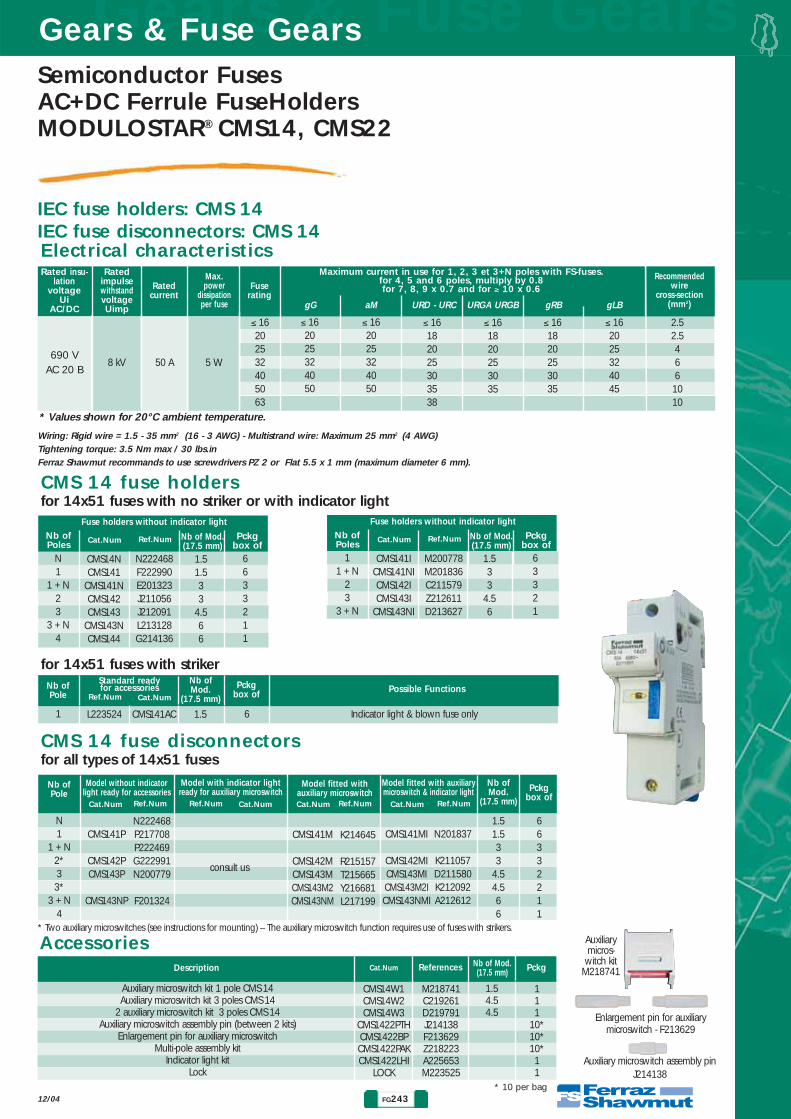
IEC fuse holders: CMS 14IEC fuse disconnectors: CMS 14
Auxiliarymicros-witch kit
M218741
Enlargement pin for auxiliary microswitch - F213629
Auxiliary microswitch assembly pinJ214138
CMS 14 fuse holdersfor 14x51 fuses with no striker or with indicator light
CMS 14 fuse disconnectorsfor all types of 14x51 fuses
Accessories
690 VAC 20 B
8 kV 50 A 5 W
≤ 16202532405063
≤ 162025324050
≤ 162025324050
≤ 16182025303538
≤ 161820253035
≤ 161820253035
≤ 162025324045
2.52.54661010
Rated insu-lation
voltageUi
AC/DC
RatedimpulsewithstandvoltageUimp
Rated current
Fuserating
Max.power
dissipationper fuse
Recommendedwire
cross-section(mm2)gG aM URD - URC URGA URGB gRB gLB
N1
1 + N23
3 + N4
N222468F222990E201323J211056J212091L213128G214136
CMS14NCMS141
CMS141NCMS142CMS143
CMS143NCMS144
1.51.533
4.566
6633211
Nb ofPoles
Nb of Mod.(17.5 mm)
Ref.NumCat.Num
Fuse holders without indicator light
Pckgbox of
* Values shown for 20°C ambient temperature.
* Two auxiliary microswitches (see instructions for mounting) – The auxiliary microswitch function requires use of fuses with strikers.
Wiring: Rigid wire = 1.5 - 35 mm2 (16 - 3 AWG) - Multistrand wire: Maximum 25 mm2 (4 AWG)Tightening torque: 3.5 Nm max / 30 lbs.inFerraz Shawmut recommands to use screwdrivers PZ 2 or Flat 5.5 x 1 mm (maximum diameter 6 mm).
11 + N
23
3 + N
M200778M201836C211579Z212611D213627
CMS141ICMS141NICMS142ICMS143I
CMS143NI
1.533
4.56
63321
N1
1 + N2*33*
3 + N4
N222468P217708P222469G222991N200779
F201324
CMS141P
CMS142PCMS143P
CMS143NP
consult us
1.51.533
4.54.566
66332211
Nb ofPole
Nb ofMod.
(17.5 mm)
Model without indicatorlight ready for accessories
Model with indicator lightready for auxiliary microswitch
K214645
R215157T215665Y216681L217199
CMS141M
CMS142MCMS143MCMS143M2CMS143NM
N201837
K211057D211580K212092A212612
CMS141MI
CMS142MICMS143MICMS143M2ICMS143NMI
Model fitted with auxiliary microswitch
Model fitted with auxiliarymicroswitch & indicator light Pckg
box of
Auxiliary microswitch kit 1 pole CMS 14Auxiliary microswitch kit 3 poles CMS 14
2 auxiliary microswitch kit 3 poles CMS 14Auxiliary microswitch assembly pin (between 2 kits)
Enlargement pin for auxiliary microswitchMulti-pole assembly kit
Indicator light kitLock
CMS14W1CMS14W2CMS14W3
CMS1422PTHCMS1422BPCMS1422PAKCMS1422LHI
LOCK
M218741C219261D219791J214138F213629Z218223A225653M223525
1.54.54.5
111
10*10*10*11
Description Nb of Mod.(17.5 mm)Cat.Num PckgReferences
for 14x51 fuses with striker
1 L223524 CMS141AC 1.5 6 Indicator light & blown fuse only
Nb ofPole
Nb ofMod.
(17.5 mm)Ref.Num Cat.Num
Standard ready for accessories Pckg
box of Possible Functions
* 10 per bag
Maximum current in use for 1, 2, 3 et 3+N poles with FS-fuses.for 4, 5 and 6 poles, multiply by 0.8for 7, 8, 9 x 0.7 and for ≥ 10 x 0.6
Electrical characteristics
Nb ofPoles
Nb of Mod.(17.5 mm)
Ref.NumCat.Num
Fuse holders without indicator light
Pckgbox of
Ref.NumCat.Num Ref.Num Cat.Num Ref.NumCat.Num Ref.NumCat.Num

Gears & Fuse GearsGears & Fuse Gears
FG244 12/04
Semiconductor FusesAC+DC Ferrule FuseHolders
MODULOSTAR® CMS14, CMS22
IEC fuse holders: CMS 22IEC fuse disconnectors: CMS 22
CMS 22 fuse holdersfor 22x58 fuses with no striker or with indicator light
Accessories
690 VAC 20 B
8 kV 125 A 9.5 W
≤ 1620253240506380100125
≤ 1620253240506380100110
≤ 1620253240506380100125
≤ 16202529354052637685
≤ 162025293540506065
≤ 162025293540506576
≤ 162025324050637585125
2.54610101016253535
Rated insu-lation
voltageUi
AC/DC
RatedimpulsewithstandvoltageUimp
Rated current
Fuserating
Max.power
dissipationper fuse
Recommendedwire
cross-section(mm2)gG aM URD - URC URGA URGB gRB gLB
N1
1 + N23
3 + N4
M213129E213628L214646V215666Z216682Q217709N218742
CMS22NCMS221
CMS221NCMS222CMS223
CMS223NCMS224
1.51.533
4.566
6633211
Nb ofPoles
Nb of Mod.(17.5 mm)
Ref.NumCat.Num
Fuse holders without indicator light
Pckgbox of
* Values shown for 20°C ambient temperature.
* Two auxiliary microswitches (see instructions for mounting) – The auxiliary microswitch function requires use of fuses with strikers.
Wiring: Rigid wire = 1.5 - 50 mm2 (16 - 1 AWG) - Multistrand wire: Maximum 35 mm2 (3 AWG). Tightening torque: max. 4.5 Nm - 45 lbs.inFerraz Shawmut recommands to use screwdrivers PZ 2 or Flat 6.5 x 1.2 mm (maximum diameter 7 mm).
11 + N
23
3 + N
H214137S215158Z216176M217200A218224
CMS22NICMS221I
CMS221NICMS222ICMS223I
CMS223NICMS224I
24468
63321
N1
1 + N2*33*
3 + N4
M213129G201325M214647T215159W215667W215667A216177
CMS22NCMS221P
CMS221NPCMS222PCMS223P
CMS223NP
consult us
22446688
66332211
Nb ofPole
Nb ofMod.
(17.5 mm)
Model without indicatorlight ready for accessories
Model with indicator lightready for auxiliary microswitch
D219262
E219792Q222470H222992P200780
CMS221M
CMS222MCMS223MCMS223M2CMS223NM
A216683
N217201R217710B218225P218743
CMS221MI
CMS222MICMS223MICMS223M2ICMS223NMI
Model fitted with auxiliary microswitch
Model fitted with auxiliarymicroswitch & indicator light Pckg
box of
Auxiliary microswitch kit 1 pole CMS 22Auxiliary microswitch kit 3 poles CMS 22
2 auxiliary microswitch kit 3 poles CMS 22Auxiliary microswitch assembly pin (between 2 kits)
Enlargement pin for auxiliary microswitchMulti-pole assembly kit
Indicator light kitLock
CMS22W1CMS22W2CMS22W3
CMS1422PTHCMS1422BPCMS1422PAKCMS1422LHI
LOCK
E211581L212093B212613J214138F213629Z218223A225653M223525
266
111
10*10*10*11
Description Nb of Mod.(17.5 mm)Cat.Num PckgReferences
for 22x58 fuses with striker
1 P201838CMS22AC 1.5 6 Indicator light & blown fuse only
Nb ofPole
Nb ofMod.
(17.5 mm)Ref.NumCat.Num
Standard ready for accessories Pckg
box of Possible Functions
* 10 per bag
Maximum current in use for 1, 2, 3 et 3+N poles with FS-fuses.for 4, 5 and 6 poles, multiply by 0.8for 7, 8, 9 x 0.7 and for ≥ 10 x 0.6
Electrical characteristics
Nb ofPoles
Nb of Mod.(17.5 mm)
Ref.NumCat.Num
Fuse holders without indicator light
Pckgbox of
Ref.NumCat.Num Ref.NumCat.Num Ref.NumCat.Num Ref.NumCat.Num
Auxiliarymicroswitch
kitE211581
Enlargement pin for auxiliary microswitch - F213629
Auxiliary microswitch assemblypin - J214138
G201325
D219262
CMS 22 fuse disconnectorsfor all types of 22x58 fuses

FG245
Gears & Fuse GearsGears & Fuse Gears
12/04
Semiconductor FusesAC+DC Ferrule FuseHoldersMODULOSTAR® CMS14, CMS22
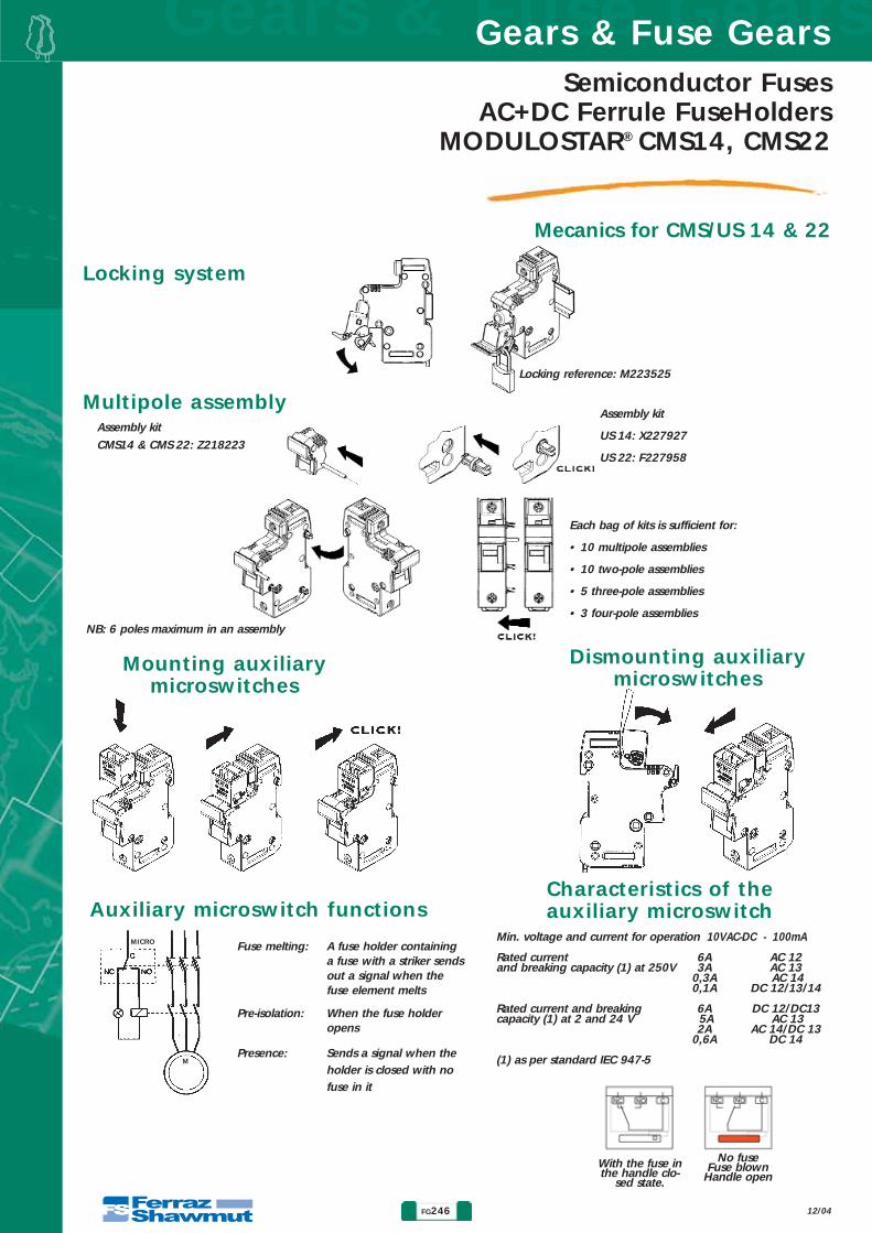
Mecanics for CMS/US 14 & 22
Dimensions of CMS 22 and US 22 products
Dimensions of CMS 14 and US 14 products
Width depending Nb poles 1 2 3 4 5 6on nb. of 17.5 mm Nb of modules 1.5 3 4.5 6 7.5 9
modules mm 26.5 53 79.5 106 132.5 159
Width depending Nb poles 1 2 3 4 5 6on nb. of 17.5 mm Nb of modules 2 4 6 8 10 12
modules mm 35 70 105 140 175 210
Gears & Fuse GearsGears & Fuse Gears
FG246 12/04
Semiconductor FusesAC+DC Ferrule FuseHolders
MODULOSTAR® CMS14, CMS22
Mecanics for CMS/US 14 & 22
With the fuse inthe handle clo-
sed state.
No fuseFuse blown
Handle open
Multipole assembly
Mounting auxiliarymicroswitches
Dismounting auxiliarymicroswitches
M
MICRO Fuse melting: A fuse holder containinga fuse with a striker sendsout a signal when thefuse element melts
Pre-isolation: When the fuse holderopens
Presence: Sends a signal when theholder is closed with nofuse in it
Min. voltage and current for operation 10VAC-DC - 100mA
Rated current 6A AC 12and breaking capacity (1) at 250V 3A AC 13
0,3A AC 140,1A DC 12/13/14
Rated current and breaking 6A DC 12/DC13capacity (1) at 2 and 24 V 5A AC 13
2A AC 14/DC 130,6A DC 14
(1) as per standard IEC 947-5
Characteristics of the auxiliary microswitchAuxiliary microswitch functions
Assembly kit
US 14: X227927
US 22: F227958
Each bag of kits is sufficient for:
• 10 multipole assemblies
• 10 two-pole assemblies
• 5 three-pole assemblies
• 3 four-pole assemblies
Assembly kit
CMS14 & CMS 22: Z218223
NB: 6 poles maximum in an assembly
Locking system
Locking reference: M223525
FG247
Gears & Fuse GearsGears & Fuse Gears
12/04
Semiconductor FusesAC+DC Ferrule FuseHoldersMODULOSTAR® CMS14, CMS22
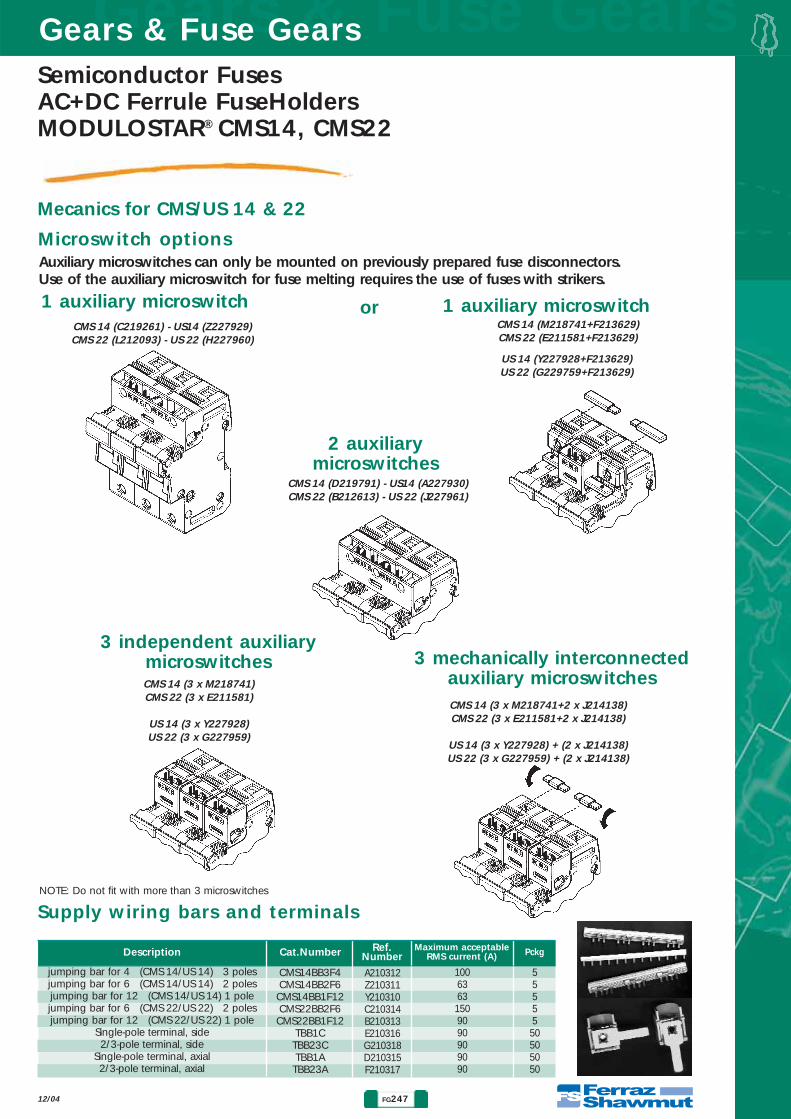
Mecanics for CMS/US 14 & 22
Microswitch options
2 auxiliarymicroswitches
1 auxiliary microswitch
Auxiliary microswitches can only be mounted on previously prepared fuse disconnectors.Use of the auxiliary microswitch for fuse melting requires the use of fuses with strikers.
NOTE: Do not fit with more than 3 microswitches
or 1 auxiliary microswitch
3 independent auxiliarymicroswitches 3 mechanically interconnected
auxiliary microswitches
CMS 14 (D219791) - US14 (A227930)CMS 22 (B212613) - US 22 (J227961)
CMS 14 (C219261) - US14 (Z227929)CMS 22 (L212093) - US 22 (H227960)
CMS 14 (M218741+F213629)CMS 22 (E211581+F213629)
US 14 (Y227928+F213629)US 22 (G229759+F213629)
CMS 14 (3 x M218741)CMS 22 (3 x E211581)
US 14 (3 x Y227928)US 22 (3 x G227959)
CMS 14 (3 x M218741+2 x J214138)CMS 22 (3 x E211581+2 x J214138)
US 14 (3 x Y227928) + (2 x J214138)US 22 (3 x G227959) + (2 x J214138)
Supply wiring bars and terminals
jumping bar for 4 (CMS 14/US 14) 3 polesjumping bar for 6 (CMS 14/US 14) 2 polesjumping bar for 12 (CMS 14/US 14) 1 polejumping bar for 6 (CMS 22/US 22) 2 polesjumping bar for 12 (CMS 22/US 22) 1 pole
Single-pole terminal, side2/3-pole terminal, side
Single-pole terminal, axial2/3-pole terminal, axial
A210312Z210311Y210310C210314B210313E210316G210318D210315F210317
10063631509090909090
5555550505050
Description
CMS14BB3F4CMS14BB2F6
CMS14BB1F12CMS22BB2F6
CMS22BB1F12TBB1C
TBB23CTBB1A
TBB23A
Cat.Number Ref.Number PckgMaximum acceptable
RMS current (A)

Gears & Fuse GearsGears & Fuse Gears
FG248 12/04
Semiconductor FusesAC+DC Ferrule FuseHolders
MODULOSTAR® CMS14, CMS22
Indicator light kit
1 Carefully remove the cover with 2 screw drivers.
2 Slip the indicator light’s top insert into the rails,being careful not to twist the contact tabs.
3 Put the cover back on
Assembly precautions in multipole assembliesWhen fuse holders are side by side or very near each other (less than one module apart), theymust be derated again, in addition to derating for temperature
Number of 17.5 mm modules1-2-34-5-67-8-9> 10
Derating factorNone = 1
0.80.70.6
With the indicator light a blown fuse can be quickly located if power is still on
1
2
3

FG249
Gears & Fuse GearsGears & Fuse Gears
12/04
Semiconductor FusesAC+DC Ferrule FuseHoldersMODULOSTAR® US14, US22
UL fuse holders: US 14
Accessories � �
750 V 8 kV 50 A 4,7 W
≤ 20≤ 25≤ 3032405063
≤ 20≤ 25≤ 30
≤ 2025
324050
18201825303538
182018253035
182018253035
≤ 162025324045
≤ 162025324045
Rated insu-lation
voltageUi
AC/DC
RatedimpulsewithstandvoltageUimp
Rated current
Fuserating
Max.power
dissipationper fuse
Recommendedwire
cross-section(mm2)gG
202530
60gD aM URD - URC URGA URGB gRB gLB
* Values shown for 20°C ambient temperature.
Wiring: Rigid wire = 1.5 - 35 mm2 (16 - 3 AWG) - Multistrand wire: Maximum 25 mm2 (4 AWG)Tightening torque: 3.5 Nm max / 30 lbs.inFerraz Shawmut recommands to use screwdrivers PZ 2 or Flat 5.5 x 1 mm (maximum diameter 6 mm).
Auxiliary contact kit 1 pole US 14Auxiliary contact kit 3 poles US 14
2 auxiliary contact kit 3 poles US 14Auxiliary contact assembly pin (between 2 kits)
Enlargement pin for auxiliary contactMulti-pole assembly kit
Indicator light kitLock
USMSW1USMSW2 USMSW3
US1422PTHUS1422BPUS14PAK
CMS1422LHILOCK
Y227928Z227929A227930J214138F213629X227927A225653M223525
1.54.54.5
111
10*10*10*11
Description Nb of Mod.(17.5 mm)Cat.Num PckgReferences
* 10 per bag
Maximum current in use for 1, 2, 3 et 3+N poles with FS-fuses.for 4, 5 and 6 poles, multiply by 0.8for 7, 8, 9 x 0.7 and for ≥ 10 x 0.6
Electrical characteristics
* Two auxiliary microswitches (see instructions for mounting) – The auxiliary microswitch function requires use of fuses with strikers
N1
1 + N22*33*
3 + N3 + N*
44*
S227900T227901Y227905C227909
J227915
Q227921
US14NUS141
US141NUS142
US143
US143N
US144
V227902Z227906D227910
K227916
R227922
US141IUS141NIUS142I
US143I
US143NI
US144I
1.51.5333
4.54.56666
66333221111
Nb ofPole
Nb ofMod.
(17.5 mm)
Model without indicatorlight ready for accessories
Model with indicator lightready for auxiliary contact
W227903A227907E227911G227913L227917N227919S227923V227925
US141MUS141NMUS142MUS142M2US143MUS143M2US143NMUS143NM2US144MUS144M2
X227904B227908F227912H227914M227918P227920T227924W227926
US141MIUS141NMIUS142MIUS142M2IUS143MIUS143M2IUS143NMIUS143NM2I
US14MIUS144M2I
Model fitted withauxiliary contact
Model fitted with auxiliarycontact & indicator light Pckg
box ofRef.NumCat.Num Ref.NumCat.Num Ref.NumCat.Num Ref.NumCat.Num
Auxiliarycontact kitY227928
Enlargement pin for auxiliary contact - F213629
Auxiliary contact assembly pinJ214138
X227904
ULTRASAFETM US 14 fuse disconnectors � �for 14x51 fuses with no striker, or with indicator light or with striker
Gears & Fuse GearsGears & Fuse Gears
FG250 12/04
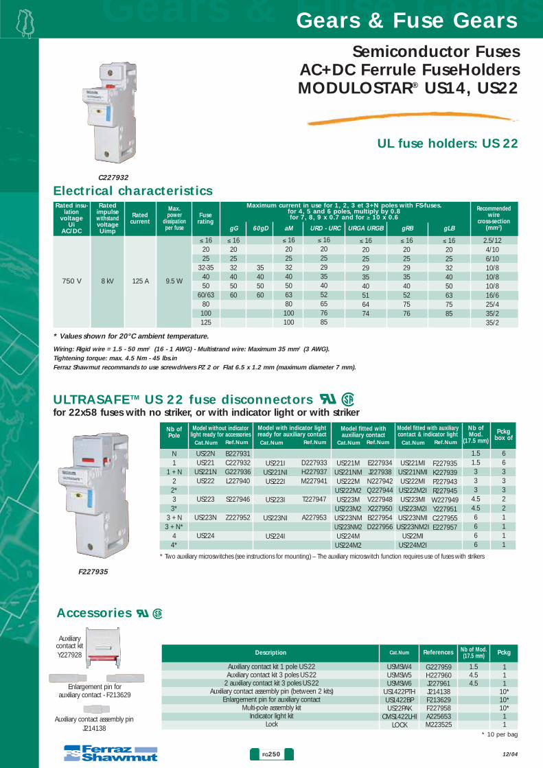
Semiconductor FusesAC+DC Ferrule FuseHoldersMODULOSTAR® US14, US22
UL fuse holders: US 22
Accessories � �
750 V 8 kV 125 A 9.5 W
≤ 162025
32-354050
60/6380100125
≤ 16202532405060
≤ 1620253240506380100100
≤ 16202529354052657685
≤ 162025293540516474
≤ 162025293540527576
≤ 162025324050637585
2.5/124/106/1010/810/810/816/625/435/235/2
Rated insu-lation
voltageUi
AC/DC
RatedimpulsewithstandvoltageUimp
Rated current
Fuserating
Max.power
dissipationper fuse
Recommendedwire
cross-section(mm2)gG
35405060
60gD aM URD - URC URGA URGB gRB gLB
* Values shown for 20°C ambient temperature.
Wiring: Rigid wire = 1.5 - 50 mm2 (16 - 1 AWG) - Multistrand wire: Maximum 35 mm2 (3 AWG). Tightening torque: max. 4.5 Nm - 45 lbs.inFerraz Shawmut recommands to use screwdrivers PZ 2 or Flat 6.5 x 1.2 mm (maximum diameter 7 mm).
Auxiliary contact kit 1 pole US 22Auxiliary contact kit 3 poles US 22
2 auxiliary contact kit 3 poles US 22Auxiliary contact assembly pin (between 2 kits)
Enlargement pin for auxiliary contactMulti-pole assembly kit
Indicator light kitLock
USMSW4USMSW5USMSW6
US1422PTHUS1422BPUS22PAK
CMS1422LHILOCK
G227959H227960J227961J214138F213629F227958A225653M223525
1.54.54.5
111
10*10*10*11
Description Nb of Mod.(17.5 mm)Cat.Num PckgReferences
* 10 per bag
Maximum current in use for 1, 2, 3 et 3+N poles with FS-fuses.for 4, 5 and 6 poles, multiply by 0.8for 7, 8, 9 x 0.7 and for ≥ 10 x 0.6
Electrical characteristics
* Two auxiliary microswitches (see instructions for mounting) – The auxiliary microswitch function requires use of fuses with strikers
N1
1 + N22*33*
3 + N3 + N*
44*
B227931C227932G227936L227940
S227946
Z227952
US22NUS221
US221NUS222
US223
US223N
US224
D227933H227937M227941
T227947
A227953
US221IUS221NIUS222I
US223I
US223NI
US224I
1.51.5333
4.54.56666
66333221111
Nb ofPole
Nb ofMod.
(17.5 mm)
Model without indicatorlight ready for accessories
Model with indicator lightready for auxiliary contact
E227934J227938N227942Q227944V227948X227950B227954D227956
US221MUS221NMUS222MUS222M2US223MUS223M2US223NMUS223NM2US224MUS224M2
F227935K227939P227943R227945W227949Y227951C227955E227957
US221MIUS221NMIUS222MIUS222M2IUS223MIUS223M2IUS223NMIUS223NM2I
US22MIUS224M2I
Model fitted withauxiliary contact
Model fitted with auxiliarycontact & indicator light Pckg
box ofRef.NumCat.Num Ref.NumCat.Num Ref.NumCat.Num Ref.NumCat.Num
Auxiliarycontact kitY227928
Enlargement pin for auxiliary contact - F213629
Auxiliary contact assembly pinJ214138
ULTRASAFETM US 22 fuse disconnectors � �for 22x58 fuses with no striker, or with indicator light or with striker
C227932
F227935

FG251
Gears & Fuse GearsGears & Fuse Gears
12/04
Semiconductor FusesAC+DC Ferrule FuseHoldersMODULOSTAR® US14, US22
Mecanics for CMS/US 14 & 22
Dimensions of CMS 22 and US 22 products
Dimensions of CMS 14 and US 14 products
Width depending Nb poles 1 2 3 4 5 6on nb. of 17.5 mm Nb of modules 1.5 3 4.5 6 7.5 9
modules mm 26.5 53 79.5 106 132.5 159
Width depending Nb poles 1 2 3 4 5 6on nb. of 17.5 mm Nb of modules 2 4 6 8 10 12
modules mm 35 70 105 140 175 210

Gears & Fuse GearsGears & Fuse Gears
FG252 12/04
Mecanics for CMS/US 14 & 22
Semiconductor FusesAC+DC Ferrule FuseHoldersMODULOSTAR® US14, US22
With the fuse inthe handle clo-
sed state.
No fuseFuse blown
Handle open
Multipole assembly
Mounting auxiliarymicroswitches
Dismounting auxiliarymicroswitches
M
MICRO Fuse melting: A fuse holder containinga fuse with a striker sendsout a signal when thefuse element melts
Pre-isolation: When the fuse holderopens
Presence: Sends a signal when theholder is closed with nofuse in it
Min. voltage and current for operation 10VAC-DC - 100mA
Rated current 6A AC 12and breaking capacity (1) at 250V 3A AC 13
0,3A AC 140,1A DC 12/13/14
Rated current and breaking 6A DC 12/DC13capacity (1) at 2 and 24 V 5A AC 13
2A AC 14/DC 130,6A DC 14
(1) as per standard IEC 947-5
Characteristics of the auxiliary microswitchAuxiliary microswitch functions
Assembly kit
US 14: X227927
US 22: F227958
Each bag of kits is sufficient for:
• 10 multipole assemblies
• 10 two-pole assemblies
• 5 three-pole assemblies
• 3 four-pole assemblies
Assembly kit
CMS14 & CMS 22: Z218223
NB: 6 poles maximum in an assembly
Locking system
Locking reference: M223525

FG253
Gears & Fuse GearsGears & Fuse Gears
12/04
Semiconductor FusesAC+DC Ferrule FuseHoldersMODULOSTAR® US14, US22
Mecanics for CMS/US 14 & 22
Microswitch options
2 auxiliarymicroswitches
1 auxiliary microswitch
Auxiliary microswitches can only be mounted on previously prepared fuse disconnectors.Use of the auxiliary microswitch for fuse melting requires the use of fuses with strikers.
NOTE: Do not fit with more than 3 microswitches
or 1 auxiliary microswitch
3 independent auxiliarymicroswitches 3 mechanically interconnected
auxiliary microswitches
CMS 14 (D219791) - US14 (A227930)CMS 22 (B212613) - US 22 (J227961)
CMS 14 (C219261) - US14 (Z227929)CMS 22 (L212093) - US 22 (H227960)
CMS 14 (M218741+F213629)CMS 22 (E211581+F213629)
US 14 (Y227928+F213629)US 22 (G229759+F213629)
CMS 14 (3 x M218741)CMS 22 (3 x E211581)
US 14 (3 x Y227928)US 22 (3 x G227959)
CMS 14 (3 x M218741+2 x J214138)CMS 22 (3 x E211581+2 x J214138)
US 14 (3 x Y227928) + (2 x J214138)US 22 (3 x G227959) + (2 x J214138)
Supply wiring bars and terminals
jumping bar for 4 (CMS 14/US 14) 3 polesjumping bar for 6 (CMS 14/US 14) 2 polesjumping bar for 12 (CMS 14/US 14) 1 polejumping bar for 6 (CMS 22/US 22) 2 polesjumping bar for 12 (CMS 22/US 22) 1 pole
Single-pole terminal, side2/3-pole terminal, side
Single-pole terminal, axial2/3-pole terminal, axial
A210312Z210311Y210310C210314B210313E210316G210318D210315F210317
10063631509090909090
5555550505050
Description
CMS14BB3F4CMS14BB2F6
CMS14BB1F12CMS22BB2F6
CMS22BB1F12TBB1C
TBB23CTBB1A
TBB23A
Cat.Number Ref.Number PckgMaximum acceptable
RMS current (A)

Gears & Fuse GearsGears & Fuse Gears
FG254 12/04
Semiconductor FusesAC+DC Ferrule FuseHoldersMODULOSTAR® US14, US22
Indicator light kit
1 Carefully remove the cover with 2 screw drivers.
2 Slip the indicator light’s top insert into the rails,being careful not to twist the contact tabs.
3 Put the cover back on
Assembly precautions in multipole assembliesWhen fuse holders are side by side or very near each other (less than one module apart), theymust be derated again, in addition to derating for temperature
Number of 17.5 mm modules1-2-34-5-67-8-9> 10
Derating factorNone = 1
0.80.70.6
With the indicator light a blown fuse can be quickly located if power is still on
1
2
3

Gears & Fuse GearsGears & Fuse Gears
FG256 12/04
Semiconductor FusesAC+DC Ferrule FuseHolders
ST22
ST Fuse Disconnectors Size 22
• IN ACCORDANCE WITH IEC 947-3 AND EN 60947-3 OPERATION CLASS: AC20B IMPULSE WITHSTAND VOLTAGE: 6 AND 8 kV (1.2/50 µs wave)
• WITH PRE-ISOLATING AND BLOWN-FUSE INDICATING MICROSWITCHES• COMPLETE PROTECTION AGAINST TOUCHING OF LIVE PARTS • PROTECTION DEGREE: IP 2X• HIGH-PERFORMANCE ST RANGE COMPLIANT WITH THE NEW EUROPEAN VOLTAGE RATINGS (IEC
33) UN 480-690 V AC/DC IN UP TO 125 A
Main Characteristics
Size
ST 22
AC Insulationvoltage
rating Ui(V) AC/DC
Maximum fuse operating current( A )
Recommended copperwire gauge (mm2)
Fuse currentratingIN( A )
CurrentratingIN( A )
Impulsewithstandvoltage
Uimp(kV)(1) gG aMURD/URC URGB/URGA gRC
gR/UR gL
Fire andfumes class
NF F 16 -102
690 (CEI)700 (US)
8 125
253240506380
100125135
46
10101616252535
I3-F1
25293540526576
25293540516474
252935405265768587
253240506380
100125
253240506380
100110
25324050637585
All terminals silver-plated copper(1) Between close phases and phase and mass, between phases and microswitch as per IEC 947-1
ST 22
Mounting with a padlocking right side-handle for ST 22
Qty. of«FO»
22112211
Qty. of«D»
10101010
ST22 IIIN FOFOD+CDELAT.D.ST22 IIIN FOFO+CDELAT.D.ST22 IIIN FOD+CDELAT.D.ST22 IIIN FO+CDELAT.D.
ST22 III FOFOD+CDELAT.D.ST22 III FOFO+CDELAT.D.ST22 III FOD+CDELAT.D.ST22 III FO+CDELAT.D.
M 209633N 209634P 209635Q 209636S 209638R 209637T 209639V 209640
DesignationRef.
NumberCatalogNumber
7.8
30 maxi.Operation handle = 25
Operation handle with extended shaft = 35 to 112
"FO
"
"D"
"FO
"
0- 2

FG257
Gears & Fuse GearsGears & Fuse Gears
12/04
Semiconductor FusesAC+DC Ferrule FuseHoldersST22
ST 22 (for 22x58 fuses)
35 35 354.5 26
15 15
9 4.5
42
27
35
3644
10
80
6x6
100
110
120
128
3570
105140
"FO""D"
Unmovable screw clamp-type connections for wires:• one conductor, multistrand or rigid wire: 35 mm2
• two conductors, multistrand wire: 16 mm2
• two conductors, rigid wire : 25 mm2
Minimal section: 2.5 mm2
With tightening torque: 2.8 to 3.5 NmMounting:
• simple snap-mounting on standard symmetricalDIN-rail
• direct on board: two M4 screws with tighteningtorque 1 to 1.2 Nm
(1) Reversing switch-style blown-fuse indication contacts (D model)(2) Reversing switch-style preisolating contacts (FO model) enabling
control of protection device and opening of off load disconnector.
Supply wiring bars and terminals
Mounting adapterBlue colored AF adapter (Ref. Number Q 098500) available for mounting on standard assymetricalDIN-rail (EN 50035) and usable for all models.
* Between power circuit and microswitch terminals according to IEC 60 and 694 and NFC 64010 (50/60 Hz 1 mn dry air).** Between power circuit and microswitch terminals Uimp: impulse voltage according to IEC 947-1.*** Between power circuit and microswitch terminals
Preisolating “FO” and blown fuse indication “D” switch characteristicsAC insulation
voltagerating(***)
Interrupting rating
Non-inductive currentInductive circuit :
L/R = 25ms
AC voltagewithstand
test(*)
Currentrating
FOorD
type
Voltage/current for
certain operating
690 V
690 V
50/60Hz
DC
20 V/50 mA
10 V/10 mA
10 A
10 A
«FO»
«D»
Current
10 A 10 A 7 A
5 A 0.5 A
10 A 8 A 6 A 7.5 kV
1.6 A 0.3 A 7.5 kV
8 kV
8 kV
30V 110V 250V 30V 110V 250V
Impulse voltageUimp1.2/50
µs(**)
1er FO 2ème FO D
ST22
open disconnectorConnecting with 6.3 clips
12 14 11 32 34 31 22 24 21
Wiring bar for 6x2 poles Size 22Wiring bar for 12x1 pole Size 22
Single-pole terminal, side2/3-pole terminal, side
Single-pole terminal, axial2/3-pole terminal, axial
C210314B210313E210316G210318D210315F210317
1509090909090
5550505050
Description References
CMS22BB2F6CMS22BB1F12
TBB1CTBB23CTBB1A
TBB23A
Catalog Number PckgMaximum acceptable RMS current (A)
Poles Symbol Cat. Num Ref.Num Pck
ST221 F220368 235 12&3
1 • ST221FO M220397 260 1• ST22ID N220398 285 1• • ST22IFOD P220399 310 1
ST221N D220389 485 6&1
1+N • ST221NFO E220620 510 1• ST221ND D220619 535 1• • ST221NFOD D220573 560 1
N ST22N E220367 250 12&3
ST222 B220387 470 6&1
2 • ST222FO R220401 495 1• ST222D S220402 520 1• • ST222FOD T220403 545 1
ST223 C220388 705 4&1
3 • ST223FO W220405 730 1• ST223D X220406 755 1• • ST223FOD Y220407 780 1
ST223N E220390 955 3&1
3+N • ST223NFO A220409 980 1• ST223ND B220410 1005 1• • ST223NFOD C220411 1030 1
4 • ST224D H205926 1030 1
Ind
icat
ion
(1)
Appro
vals
Wei
gh
t (g
)
Pred
iscon
nect
ion(2
)

Gears & Fuse GearsGears & Fuse Gears
FG258 12/04
Semiconductor FusesAC+DC Ferrule FuseHolders
ST22
ST22 with ring pug connection
Poles FO D Right Handle Designation Reference Number Catalog Number
1 / / No ST 22 Plage Type B B228828 ST22RING/ 1 No ST 22 D Plage Type B C229910 ST22DRING/ /
NoST 22 II Plage Type B K210873 ST222RING
2 2 1 ST 22 II FOFOD Plage Type B L210874 ST222FOFODRING
2 1 Yes ST22 II FOFOD Cde Lat. D Plage Type B M210875 ST222LHFOFODRIN
/ / No ST22 III Plage Type B N210876 ST223RING
3 2 1 No ST22 III FOFOD Plage Type B P210877 ST223FOFODRING
2 1 Yes ST22 III FOFOD Cde Lat. DPlage Type B Q210878 ST223LHFOFODRIN
4 2 1 Yes ST 22 IV FOFOD Cde Lat. DPlage Type B" M227711 ST224LHFOFODRIN

FG259
Gears & Fuse GearsGears & Fuse Gears
12/04
Semiconductor FusesAC+DC Ferrule FuseHoldersMODULOSTAR® CMS27, UltraSafe US27
MODULOSTAR®: CMS27 Fuse HolderULTRASAFETM: US27 Fuse Disconnector
• Conforms to the standards:UL 512 AND UL 840 CSA 22-2 N° 39EN 60947-1 & 3 (Class : AC20B)
• Rated insulation voltage Ui= 800VAC-DC
• Full protection against accidentally touching live parts. Protection degree: IP 2XB in accordance with the IEC standard 60529.
• High performance, conforming to European standards (Attachment toDIN rail - Modular fuse-disconnector).
• The US27 models have c US approval.
Electric Characteristics
Insulation voltage Impulse Current Fuse Maxi fuse operating current (A) RecommendedAC UI withstand voltage rating current rating 660V
60gDcopper wire gauge
in V AC/DC Uimp (kV) IN (A) IN (A) URGD660V URQ-URSCC 660V-800VgRB 1000V URB
AWG mm2
8 - WITHOUT DERATING - 18 110 - WITHOUT DERATING - 18 112 - WITHOUT DERATING - 18 116 - WITHOUT DERATING - 18 120 - WITHOUT DERATING - 18 125 - WITHOUT DERATING - 12 432 32 32 32 29 10 640 40 40 40 36 8 10
800 (CEI) / (US) 8 150 50 50 45 50 42 8 1063-65 55 65 55 63 50 6 16
80 61 80 60 80 60 6 16100 75 100 72 96 72 4 25110 - - 102 - 3 30125 91 90 - 90 3 35160 112 110 - 109 3 35170 - - - 112 3 35200 130 130 - - 1 50*250 138 138 - - 1 50*
* Busbar and ring lug connection
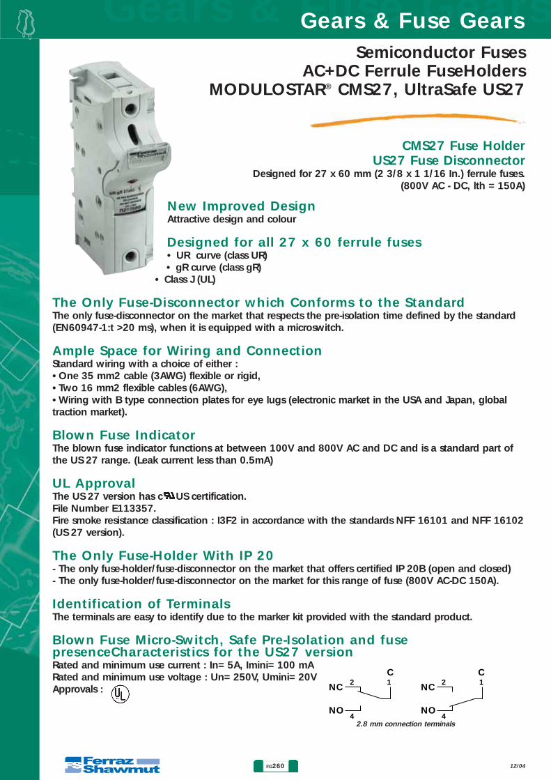
New Improved DesignAttractive design and colour
Designed for all 27 x 60 ferrule fuses• UR curve (class UR)• gR curve (class gR)
• Class J (UL)
The Only Fuse-Disconnector which Conforms to the StandardThe only fuse-disconnector on the market that respects the pre-isolation time defined by the standard(EN60947-1:t >20 ms), when it is equipped with a microswitch.
Ample Space for Wiring and ConnectionStandard wiring with a choice of either :•One 35 mm2 cable (3AWG) flexible or rigid,•Two 16 mm2 flexible cables (6AWG),•Wiring with B type connection plates for eye lugs (electronic market in the USA and Japan, globaltraction market).
Blown Fuse IndicatorThe blown fuse indicator functions at between 100V and 800V AC and DC and is a standard part ofthe US 27 range. (Leak current less than 0.5mA)
UL ApprovalThe US 27 version has c US certification.File Number E113357.Fire smoke resistance classification : I3F2 in accordance with the standards NFF 16101 and NFF 16102(US 27 version).
The Only Fuse-Holder With IP 20- The only fuse-holder/fuse-disconnector on the market that offers certified IP 20B (open and closed)- The only fuse-holder/fuse-disconnector on the market for this range of fuse (800V AC-DC 150A).
Identification of TerminalsThe terminals are easy to identify due to the marker kit provided with the standard product.
Blown Fuse Micro-Switch, Safe Pre-Isolation and fusepresenceCharacteristics for the US27 versionRated and minimum use current : In= 5A, Imini= 100 mARated and minimum use voltage : Un= 250V, Umini= 20VApprovals :
Gears & Fuse GearsGears & Fuse Gears
FG260
Semiconductor FusesAC+DC Ferrule FuseHolders
MODULOSTAR® CMS27, UltraSafe US27
CMS27 Fuse HolderUS27 Fuse Disconnector
12/04
Designed for 27 x 60 mm (2 3/8 x 1 1/16 In.) ferrule fuses.(800V AC - DC, lth = 150A)
NC
NO
NC
NO
2C C
4
2
4
11
2.8 mm connection terminals

Semiconductor FusesAC+DC Ferrule FuseHoldersMODULOSTAR® CMS27, UltraSafe US27
FG261
Gears & Fuse GearsGears & Fuse Gears
CMS27 Fuse HolderUS27 Fuse Disconnector
12/04
27x60 Fuses used ApplicationsRanges UN IN
(6,621 CP URGD 27.60 …) 660VAC 63 to 250A Class aR - Protection of semiconductor equipment,(6,621 CP URQ, URS 27.60…) 660VAC 32 to 250A e.g. Soft starters, static relays, or regulators.
(821 CP gRB 27.60...) 800VAC 8 to 110A Class gR - Protection of cables, semiconductor equipment and AC instrument circuits.
(1021 CP URB 27.60…) 1000VAC 25 to 170A Class aR - Protection of semiconductor equipment, e.g. Soft starters, static relays, regulators.
(CC 4,421 CP gLB 27.60…) 440VDC 125 to 160A Protection of DC instrument circuits, traction auxiliary circuits,(CC 6,621 CP gRB 27.60…) 660VDC 0.8 to 125A DC fed converters.
Versatile Methods of MountingOption of mounting the fuse-holder with phase and neutral poles, aswell as micro-switches, due to the connection accessories.
Several Kinds of Attachment- With M4 screws,- 35 mm or 75 mm symmetric DIN rail*,- Asymmetric DIN rail with adapter (Ref. Q098500).
* Need of 15 mm distance between DIN rail and panel
Possibility of Using Connection PlatesFor a cable with a diameter greater than either a 35 mm2 rigid or flexible cable, or two 16 mm2 flexi-ble cables, the connection can be made usingeye lug wire. Protection covers are provided with this series to safeguard against accidental contact. Connection toconnection plates, for cables equipped with ring or fork-type lugs.
Climatic Conditions of UseThis range of products has been designed for use in temperate, tropical and equatorial climates, provi-ded that the following temperature/humidity conditions are not exceeded :
Maximum temperature °C 20 40 50Maximum relative humidity % 95 80 50
Resistance to VibrationsTest with sinusoidal vibrations, scanning the three main axes of the holder.Spectrum : • 1st segment (2-16Hz) constant displacement
x = 5 mm peak• 2nd segment (16-250Hz) constant acceleration
γ = 5g peakExponential scanning speed : 1 octave per minute.Duration : 2 hours per axis.
Semiconductor FusesAC+DC Ferrule FuseHolders
MODULOSTAR® CMS27, UltraSafe US27
Gears & Fuse GearsGears & Fuse Gears
FG262 12/04
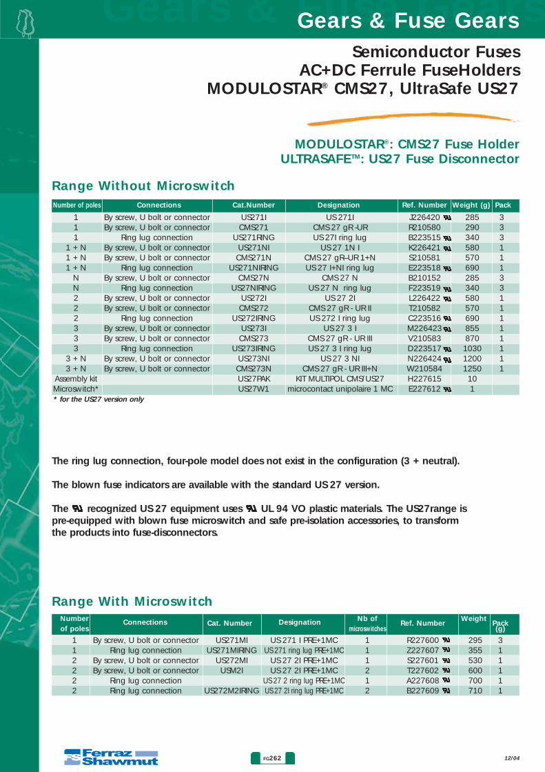
MODULOSTAR®: CMS27 Fuse HolderULTRASAFETM: US27 Fuse Disconnector
Range Without Microswitch
The ring lug connection, four-pole model does not exist in the configuration (3 + neutral).
The blown fuse indicators are available with the standard US 27 version.
The recognized US 27 equipment uses UL 94 VO plastic materials. The US27range ispre-equipped with blown fuse microswitch and safe pre-isolation accessories, to transformthe products into fuse-disconnectors.
Range With Microswitch
Number of poles Connections Cat.Number Designation Ref. Number Weight (g) Pack
Number Connections Cat. Number Designation Nb of Ref. Number
Weight Pack
of poles microswitches (g)
1 By screw, U bolt or connector US271MI US 271 I PRE+1MC 1 R227600 295 31 Ring lug connection US271MIRING US 271 ring lug PRE+1MC 1 Z227607 355 12 By screw, U bolt or connector US272MI US 27 2I PRE+1MC 1 S227601 530 12 By screw, U bolt or connector USM2I US 27 2I PRE+1MC 2 T227602 600 12 Ring lug connection US 27 2 ring lug PRE+1MC 1 A227608 700 12 Ring lug connection US272M2IRING US 27 2I ring lug PRE+1MC 2 B227609 710 1
1 By screw, U bolt or connector US271I US 271I J226420 285 31 By screw, U bolt or connector CMS271 CMS 27 gR -UR R210580 290 31 Ring lug connection US271RING US 27I ring lug B223515 340 3
1 + N By screw, U bolt or connector US271NI US 27 1N I K226421 580 11 + N By screw, U bolt or connector CMS271N CMS 27 gR–UR 1+N S210581 570 11 + N Ring lug connection US271NIRING US 27 I+NI ring lug E223518 690 1
N By screw, U bolt or connector CMS27N CMS 27 N B210152 285 3N Ring lug connection US27NIRING US 27 N ring lug F223519 340 32 By screw, U bolt or connector US272I US 27 2I L226422 580 12 By screw, U bolt or connector CMS272 CMS 27 gR - UR II T210582 570 12 Ring lug connection US272IRING US 272 I ring lug C223516 690 13 By screw, U bolt or connector US273I US 27 3 I M226423 855 13 By screw, U bolt or connector CMS273 CMS 27 gR - UR III V210583 870 13 Ring lug connection US273IRING US 27 3 I ring lug D223517 1030 1
3 + N By screw, U bolt or connector US273NI US 27 3 NI N226424 1200 13 + N By screw, U bolt or connector CMS273N CMS 27 gR - UR III+N W210584 1250 1
Assembly kit US27PAK KIT MULTIPOL CMS/US27 H227615 10Microswitch* US27W1 microcontact unipolaire 1 MC E227612 1* for the US27 version only
Semiconductor FusesAC+DC Ferrule FuseHoldersMODULOSTAR® CMS27, UltraSafe US27
FG263
Gears & Fuse GearsGears & Fuse Gears
12/04
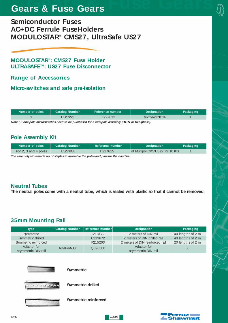
MODULOSTAR®: CMS27 Fuse HolderULTRASAFETM: US27 Fuse Disconnector
Range of Accessories
Micro-switches and safe pre-isolation
Note : 2 one-pole microswitches need to be purchased for a two-pole assembly (Ph+N or two-phase).
Pole Assembly Kit
Neutral TubesThe neutral poles come with a neutral tube, which is sealed with plastic so that it cannot be removed.
35mm Mounting Rail
Number of poles Catalog Number Reference number Designation Packaging
1 US27W1 E227612 Microswitch 1P 1
Number of poles Catalog Number Reference number Designation Packaging
For 2, 3 and 4 poles US27PAK H227615 Kit Multipol CMS/US 27 for 10 Kits 1
Type Catalog Number Reference number Designation Packaging
Symmetric J213172 2 meters of DIN rail 40 lengths of 2 mSymmetric drilled C213672 2 meters of DIN drilled rail 40 lengths of 2 m
Symmetric reinforced R215203 2 meters of DIN reinforced rail 20 lengths of 2 mAdaptor for ADAP-RASST Q098500 Adaptor for 50
asymmetric DIN rail asymmetric DIN rail
The assembly kit is made up of staples to assemble the poles and pins for the handles.
Symmetric
Symmetric drilled
Symmetric reinforced

Gears & Fuse GearsGears & Fuse Gears
FG264
Semiconductor FusesAC+DC Ferrule FuseHolders
MODULOSTAR® CMS27, UltraSafe US27
12/04
Dimensions CMS27, US27
8
6.5
87
57
117
120
80
40
405.25
118
3
146
Fixation130
Fixation40
Fixation
35
25.5
75
Connection by fixed terminal screw-clamps for wires. Maximum section:• One conductor, rigid or multistrand : Maximum 35 mm2 (3 AWG)• 2 conductors, multistrand : 16 mm2 (6 AWG) or rigid with tightening torque : 2.8 - 3.5 Nm (30 lbs.in)• Ferraz Shawmut recommands to use screwdrivers PZ 3 or Flat 8 x 1.2 mm (maximum diameter 8 mm).• Ring lug connection.
Mounting:• Simple snap mounting on 35 mm symmetric DIN rail (standard EN 50022) and 75 mm with
2 locking positions*.• Directly onto the board with M4 screws and tightening torque from 1 to 1.2 Nm (11 lbs.in)• On 35 mm asymmetric DIN rail with adaptor (Ref. Q098500)
* Need of 15 mm distance between DIN rail and panel

Semiconductor FusesAC+DC Ferrule FuseHoldersMODULOSTAR® CMS27, UltraSafe US27
FG265
Gears & Fuse GearsGears & Fuse Gears
12/04
Dimensions CMS27, US27for ring lugs connections

Gears & Fuse GearsGears & Fuse Gears
FG266
Semiconductor FusesAC+DC Ferrule FuseHolders
PS27
FUSE HOLDERS AND FUSE DISCONNECTORSFOR FERRULE-TYPE FUSES
12/04
• SOLID ASSEMBLY OFFERING GOOD THERMAL ANDMECHANICAL WITHSTANDS
• FUSE MOUNTING IN HOLDERS OR DISCONNECTORS WITHOR WITHOUT PREISOLATING AND BLOWN-FUSE INDICA-TING MICROSWITCHES
• PHENOLIC RESIN MODELS FOR BASIC APPLICATIONS -FIBER GLASS POLYESTER FOR APPLICATIONS IN CORROSI-VE ATMOSPHERES OR IN TRACTION
• COMPLYING WITH IEC 947-3 STANDARD ( AC 20 A CLASS )
• Ui = 1,000 V AC - 1,250 V DC
PSI 27x60+MC PS
PSIII 27x60+PRE+MC PS
Main Characteristics
DesignationMaximum operating current of fuse ( A ) Recommended
copper wiresize mm2
Fuse currentratingIN( A )
Insulation voltage rating Ui
AC 50/60 Hz or DC
PSI 27x60PSII 27x60PSIII 27x60PSIV 27x60
PSI 27x60 PREPSII 27x60 PREPSIII 27x60 PREPSIV 27x60 PRE
190
225
200
225
1000 V AC
1250 V DC
with or withoutterminal covers
110
125
160170
200
250
50
70
95
120
basicmodel
UL 94 V1salt
spray-proofmodel
UL 94 V0
660 VURQ
AC660VURGD
AC1000VURB
=660 VgRB
=440 VgLB
Fire andfumes class
nooperating
limit
Impulse voltage 1.2/50 µs (IEC694 et CEI 60)R.M.S. voltage 1 mn 50/60 Hz
Between close phases and phase and massBetween phases and microswitch
9 kV14 kV
12 kV
Dielectric withstand tests
Basic modelMax. temperature (°C)/ Relative humidity (%): 20 °C/95% - 40°C/80% - 50°C/50%Salt spray-proof model: (BS type)Moist tropical and equatorial climate. Corrosive atmosphere.
Connecting with two screws M8 (maximum tightenning torque 13.5 mN) on silver plated terminals the 95 mm2 max. cable with copper terminals or with 20 x 8 max. rigid or flexible bar.
Ref. NumberB 220088C 220089D 220090E 220091R 220240S 220632P 220215S 220356
DesignationPSI 27x60PSII 27x60PSIII 27x60PSIV 27x60
PSI 27x60+MCS BSPSII 27x60+MCS BSPSIII 27x60+MCS BSPSIV 27x60+MCS BS
Catalog NumberPS271PS272PS273PS274
PS271MCSBSPS272MCSBSPS273MCSBSPS274MCSBS
Packaging3 pieces2 pieces1 piece1 piece2 pieces2 pieces1 piece1 piece
Weight (g)300560920
1150330600900
1200
Fuse Holders and Accessories
4
21
3593
150 15
24
71
¯6.52.5 7.5 ¯11.5
MCS BS
Mounting : Direct on board or bar with twoM6 screws - see below drilling diagram

Semiconductor FusesAC+DC Ferrule FuseHoldersPS27
FG267
Gears & Fuse GearsGears & Fuse Gears
FUSE HOLDERS AND FUSE DISCONNECTORSFOR FERRULE-TYPE FUSES
12/04
Ref. NumberH 220071J 220072K 220073L 220074M 220075 N 220076 P 220077 Q 220078
Cat. NumberPS271PREPS272PREPS273PREPS274PRE
PS271PREMCPSPS272PREMCPSPS273PREMCPSPS274PREMCPS
Cat. NumberPS271PREBSPS272PREBSPS273PREBSPS274PREBS
PS271PREBSMCPSPS272PREBSMCPSPS273PREBSMCPSPS274PREBSMCPS
Designation (basic model)PSI 27x60 PREPSII 27x60 PREPSIII 27x60 PREPSIV 27x60 PRE
PSI 27x60 PRE+MC PSPSII 27x60 PRE+MC PSPSIII 27x60 PRE+MC PSPSIV 27x60 PRE+MC PS
Packaging3 pieces2 pieces1 piece1 piece2 pieces2 pieces1 piece1 piece
Weight (g)400800
13001700500 900
1400 1800
Ref. NumberR 220079S 220080T 220081V 220082W 220083 X 220084 Y 220085 Z 220086
Catalog Number (salt spray-proof model)PSI 27x60 PRE BSPSII 27x60 PRE BSPSIII 27x60 PRE BSPSIV 27x60 PRE BS
PSI 27x60 PRE BS+MC PSPSII 27x60 PRE BS+MC PSPSIII 27x60 PRE BS+MC PSPSIV 27x60 PRE BS+MC PS
Packaging3 pieces2 pieces1 piece1 piece2 pieces2 pieces1 piece1 piece
Weight (g)500
103015402080540
1100 1600 2100
Fuse Disconnectors and Accessories
4
21
57
14
20
42
1
35
46
24
Y
7110
7
146
180
15V
ø6.52.5 7.5 ø11.5
ZZ'
WW'
MC PS
V: 93 Connecting distance between centersW: 150 Without terminals cover lengthW’: 240 With terminals cover lengthY: 196 Space factor with a 90° fuse carrier positionZ: 284 Without terminal cover, space factor with a 180° fuse carrier positionZ’: 279 With terminal cover, space factor with a 180° fuse carrier position
A
Microswitchrated current
Preisolating and blown fuse indicating microswitch features
Non-inductive circuitinterrupting rating
3A - 250V3A - 30V
0.5A - 110V
3A - 50 Hz
3A - DC
B
• Reliable minimum operating voltage/current : 10V - 10mA
• Connecting with 6.35 mm lug
Twin terminal coversPS 27
Part #: A 220087Weight: 30g
Packaging: 3 twins
Quantityof poles
A B
3977
115153
5391
129167
1234

Gears & Fuse GearsGears & Fuse Gears
FG268
Semiconductor FusesAC+DC Ferrule FuseHolders
PS 20 x 127
FUSE HOLDERS AND FUSE DISCONNECTORSFOR FERRULE-TYPE FUSES 20x127
12/04
• SOLID ASSEMBLY OFFERING GOOD THERMAL ANDMECHANICAL WITHSTANDS
• FUSE MOUNTING IN HOLDERS OR DISCONNECTORSWITH OR WITHOUT PREISOLATING AND BLOWN-FUSEINDICATING MICROSWITCHES
• PHENOLIC RESIN MODELS FOR BASIC APPLICATIONSFIBER-GLASS POLYESTER FOR APPLICATIONS IN CORROSI-VE ATMOSPHERES OR IN TRACTION
• Ui = 1,500 V AND 2,500 V
PSI 20x127+MC PS
PSI 20x127+PRE+MC PS
Main Characteristics
Designation
Maximum operating current of fuse ( A )
Advised copperwire size
mm2
Fuse currentratingIN( A )
Insulation voltage rating Ui
AC 50/60 Hz or DC
PSI 20x127PSI 20x127 PREPSII 20x127 PREPSIII 20x127 PREPSIV 20x127 PRE
1500 V without terminal covers2500 V with
terminal coversand only salt
spray -proof model
506380
100125
1016253550
basic modelUL 94 V1
saltspray-proof
modelUL 94 V0
AC150VgRD
AC150VgRB
5056
AC1000VgRB
=1000 VgRC
8090
100
1000 VgLB
Fire andfumes class
nooperating
limit
Connecting with 50 mm2 max. cable with copper terminals or with a 15 x 8 max. rigid or flexible bar.
Impulse voltage 1.2/50 µs (IEC694 et CEI 60)R.M.S. voltage 1 mn 50/60 Hz
Between close phases and phase and massBetween phases and microswitch
6kV(1) - 10 kV(2)12 kV
12 kV(1) - 20 kV(2)
Dielectric withstand tests
Connecting with 16mm max. width, 5mm max. thick terminal
4
2
1
35 15
21
20 20
Ø 12 Ø 6,5
20
2275
64
162
208
5
64
15.5
EpaisseurThickness
98
Ø 19
MCS BS
Cat N°: PMC20+22Ref N°: K 100036Weight: 40gPackaging: 1
Ref. NumberX 097310X 220130
DesignationPSI 20x127
PSI 20x127+MCS BS
Catalog NumberPS201
PS201MCSBS
Packaging3 pieces2 pieces
Weight (g)260290
Fuse Holders and Accessories
(1) Basic modelMax. temperature (°C)/ Relative humidity (%): 20 °C/95% - 40°C/80% - 50°C/50%If Holder has to be kept off, and an heating system fed during stop periods must be used. Purpose is to keep the temperature of cubicle at alevel just a little higher than outdoor temperature.(2) Salt spray-proof model (BS type)Moist tropical and equatorial climate. Corrosive atmosphere.

Semiconductor FusesAC+DC Ferrule FuseHoldersPS 20 x 127
FG269
Gears & Fuse GearsGears & Fuse Gears
FUSE HOLDERS AND FUSE DISCONNECTORSFOR FERRULE-TYPE FUSES 20x127
12/04
Ref. NumberF 097203G 097227H 097228J 097229H 097205 D 097293 E 097294 F 097295
Cat. NumberPS201PREPS202PREPS203PREPS204PRE
PS201PREMCPSPS202PREMCPSPS203PREMCPSPS204PREMCPS
Cat. NumberPS201PREBSPS202PREBSPS203PREBSPS204PREBS
PS201PREBSMCPSPS202PREBSMCPSPS203PREBSMCPSPS204PREBSMCPS
Designation (basic model)PSI 20x127 PREPSII 20x127 PREPSIII 20x127 PREPSIV 20x127 PRE
PSI 20x127 PRE+MC PSPSII 20x127 PRE+MC PSPSIII 20x127 PRE+MC PSPSIV 20x127 PRE+MC PS
Packaging3 pieces2 pieces1 piece1 piece2 pieces2 pieces1 piece1 piece
Weight (g)400800
12001510430 880
1200 1700
Ref. NumberG 097204L 097231T 097261C 097292J 097206 G 097296 H 097297 J 097298
Catalog Number (salt spray-proof model)PSI 20x127 PRE BSPSII 20x127 PRE BSPSIII 20x127 PRE BSPSIV 20x127 PRE BS
PSI 20x127 PRE BS+MC PSPSII 20x127 PRE BS+MC PSPSIII 20x127 PRE BS+MC PSPSIV 20x127 PRE BS+MC PS
Packaging3 pieces2 pieces1 piece1 piece2 pieces2 pieces1 piece1 piece
Weight (g)490
100015001700520
103015301730
Fuse Disconnectors and Accessories
V: Connecting distance between centersW: Without terminal cover lengthW’: With terminal cover lengthY: Space factor with a 90° fuse carrier positionZ: Without terminal cover, space factor with a 180° fuse carrier positionZ’: With terminal cover, space factor with a 180° fuse carrier position
Microswitchrated current
Preisolating and blown fuse indicating microswitch features
Non-inductive circuitinterrupting rating
3A - 250V3A - 30V
0.5A - 110V
3A - 50 Hz
3A - DC
• Reliable minimum operating voltage/current : 10V / 10mA
• Connecting with 6.35 mm lug
Quantityof poles
A B
3569
103137
5084
118152
1234
4
21
57
3110
4
2
1
Ø 12 Ø 6,520 20
V=162W=208
W'=278
213
35
,5
64
10
0
Y
198
8
53
35 15
75
Z=400
Z'=435
MC PS
A
BTwin terminal coversPS 20
Part #: F 097226Weight: 20g
Packaging: 3 twins
4
2
1
8 8
1010
Distances when mounting on a conductiveboard @ Ui= 2500 VAC

Gears & Fuse GearsGears & Fuse Gears
FG270
Semiconductor FusesAC+DC Ferrule FuseHolders
SI Bases for 20 & 36
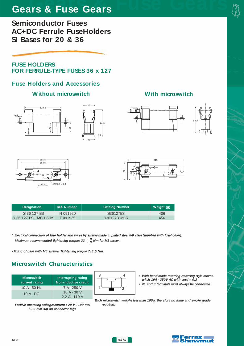
FUSE HOLDERSFOR FERRULE-TYPE FUSES 36 x 127
12/04
• STURDY ASSEMBLY WITH VERY HIGH COLLISION WITHSTAND• MOUNTING AS BASE WITH OR WITHOUT MICROSWITCH• POLYESTER ISOLATORS FOR ALL APPLICATIONS
DesignationThermal
current rating(lth)*
Maximumpower
(W)
Insulation voltage Ui (AC 50/60 Hz & DC)
(According to VDE 0110 : 565 - C group)
Fire andfumes class
Dielectric withstand test
RMS voltage1 mn 50/60 Hz
(1)
Impulse voltage
1.2/50ms
10 kV (1)
phase-ground
9 kVphase-microswitch
Consult us
phase-microswitch UL 94-VO(1) Tests according to IEC 60 & 694 and
NF C 64010Dry atmosphere, new fuse holder
SI 36 x 127 BS FittedSI 36 x 127 BS 200A to 2 500 V+ MC 1-5 BS FERRAZ
SHAWMUTfuses
Note: SI 36 x 127 BS fuse holder may be used for rolling stock.
Vibration withstand:Tests with sine vibrations carried out at ambient, scanning each of the three main axes of the holder.Spectrom: 1st segment (2 to 16 Hz) constant displacement x = 5 mm peak.
2nd segment (16 to 250 Hz) constant acceleration γ = 5 g peak.Exponential scanning speed: 1 octave per minute.Duration: 2 hours per axis
Main Characteristics
Semiconductor FusesAC+DC Ferrule FuseHoldersSI Bases for 20 & 36
FG271
Gears & Fuse GearsGears & Fuse Gears
FUSE HOLDERSFOR FERRULE-TYPE FUSES 36 x 127
12/04
129.5
M8
36 49
42
10
96.5
28
2 trous Ø 5.5
163.5185.5
37.5
45
96,5
65
215
Designation Ref. Number Weight (g)Catalog Number
* Electrical connection of fuse holder and wires by screws made in plated steel 8-8 class (supplied with fuseholder).
Maximum recommended tightening torque: 22 Nm for M8 screw.
- Fixing of base with M5 screws. Tightening torque 7±1,5 Nm.
SI 36 127 BS N 091920 SI36127BS 406SI 36 127 BS + MC 1-5 BS E 091935 SI36127BSMCR 456
Microswitchcurrent rating
Interrupting ratingNon-inductive circuit
10 A - 50 Hz 7 A - 250 V
10 A - DC 10 A - 30 V2,2 A - 110 V
Positive operating voltage/current : 20 V - 100 mA 6.35 mm slip on connector tags
3 4
1 2
• With hand-made resetting reversing style micros-witch 10A - 250V AC with cos j = 0.3
• #1 and 3 terminals must always be connected
Each microswitch weighs less than 100g, therefore no fume and smoke graderequired.
Microswitch Characteristics
Without microswitch With microswitch
Fuse Holders and Accessories
+ 0- 8
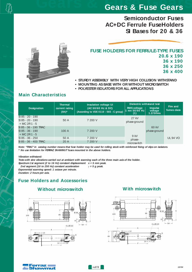
Gears & Fuse GearsGears & Fuse Gears
FG272
Semiconductor FusesAC+DC Ferrule FuseHolders
SI Bases for 20 & 36
FUSE HOLDERS FOR FERRULE-TYPE FUSES20.6 x 190
36 x 19036 x 25036 x 400
12/04
Ll
103 85K
54
15
Ø 60
A
10
10
14
14
D
35
F
4 x Ø 8.5
Ll
103
65
85K
54
15
Ø 60
A
10
10
14
14
D
35
F
4 x Ø 8.5
Fuse Holders and Accessories
Without microswitch With microswitch
Note: “TRAC” in catalog number means that fuse holder may be used for rolling stock with reinforced fixing of clips on isolators.* No use limitation for FERRAZ SHAWMUT fuses mounted in the above holders.
Vibration withstand:Tests with sine vibrations carried out at ambiant with scanning each of the three main axis of the holder.Spectrum:1st segment (2 to 16 Hz) constant displacement x = 5 mm peak.
2nd segment (16 to 250 Hz) constant acceleration γ = 5 g peak.Exponential scanning speed: 1 octave per minute.Duration: 2 hours per axis.
• STURDY ASSEMBLY WITH VERY HIGH COLLISION WITHSTAND• MOUNTING AS BASE WITH OR WITHOUT MICROSWITCH• POLYESTER ISOLATORS FOR ALL APPLICATIONS
DesignationThermal
current rating(lth)*
Insulation voltage Ui (AC 50/60 Hz & DC)
(According to VDE 0110 : 565 - C group)
Fire andfumes class
Dielectric withstand test
RMS voltage1 mn 50/60 Hz
(1)
Impulse voltage
1.2/50ms
27 kV phase-ground
9 kVphase-
microswitch
60 kVphase-ground
UL 94 VO
SI 85 - 20 - 190SI 85 - 20 - 190 50 A 7 200 V+ MC 2R 1 - 5
SI 85 - 36 - 190 TRACSI 85 - 36 - 190 100 A 7 200 V+ MC 2R 1 - 5
SI 85 - 36 - 250 50 A 7 200 VSI 85 - 36 - 400 TRAC 20 A 7 200 V
Main Characteristics
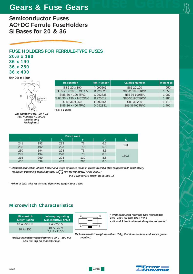
Semiconductor FusesAC+DC Ferrule FuseHoldersSI Bases for 20 & 36
FG273
Gears & Fuse GearsGears & Fuse Gears
12/04
FUSE HOLDERS FOR FERRULE-TYPE FUSES20.6 x 19036 x 19036 x 25036 x 400
Catalog NumberRef. Number Weight (g)Designation
Dimensionsl L A F D K
* Electrical connection of fuse holder and wires by screws made in plated steel 8-8 class (supplied with fuseholder).
maximum tightening torque advised: 22 Nm for M8 screw. (SI 85 36x ...)
9 ± 2 Nm for M6 screw. (SI 85 20x ...)
- Fixing of base with M8 screws. Tightening torque 10 ± 2 Nm.
SI 85 20 x 190 Y 092665 950SI 85 20 x 190 + MC 1-5 B 220525 1 050
SI 85 36 x 190 TRAC C 092738 1 080SI 85 36 x 190 + MC 2R1-5 B 220617 1 180
SI 85 36 x 250 P 092864 1 170SI 85 36 x 400 TRAC D 092831 1 400
241 192 223 73 6.5 131288 192 223 73 6.5250 194 228 73 8.5299 194 228 73 8.5 150.5316 260 294 139 8.5455 399 433 266 8.5
64
15.5
EpaisseurThickness
98
Ø 19
Cat. Number: PMCP 20 + 22Ref. Number: K 100036
Weight: 40 gPackaging: 1
Pack : 1 piece
+ 0- 8
Microswitchcurrent rating
Interrupting ratingNon-inductive circuit
10 A - 50 Hz 7 A - 250 V
10 A - DC 10 A - 30 V2,2 A - 110 V
Positive operating voltage/current : 20 V - 100 mA 6.35 mm slip on connector tags
3 4
1 2
• With hand reset reversing-type microswitch10A - 250V AC with cos ϕ = 0.3• #1 and 3 terminals must always be connected
Each microswitch weighs less than 100g, therefore no fume and smoke graderequired.
Microswitch Characteristics
for 20 x 190:
SI85-20-190SI85-20190TRACM
SI85-36-190TRASI85-36190TRACM
SI85-36-250SI85-36400TRAC