ge.com island chimney vent hoodpdf.lowes.com/operatingguides/084691174769_oper.pdf · profile...
TRANSCRIPT

Isla
nd C
him
ney
Vent
Hoo
dPr
ofile
49-80550 12-08 JR
Safety Instructions . . . . . . . . . 2, 3
Operating InstructionsLight Controls . . . . . . . . . . . . . . . . . . . .4Vent Controls . . . . . . . . . . . . . . . . . . . . .4
Care and CleaningGrease Filters . . . . . . . . . . . . . . . . . . . .5Hood Lights . . . . . . . . . . . . . . . . . . . . . .6Stainless Steel Surfaces . . . . . . . . . . .6
Installation InstructionsInstallation Preparation . . . . . . . .7-15Vented to the Outside . . . . . . . .16-20Recirculating . . . . . . . . . . . . . . . . .21-26
Troubleshooting Tips . . . . .27, 28
Consumer SupportConsumer Support . . . . . . . . . . . . . 30Warranty . . . . . . . . . . . . . . . . . . . . . . . 29
PV977
Owner’s Manual andInstallation Instructions
ge.com
Write the model and serial numbers here:
Model # __________________________
Serial # __________________________
You can find them on a label on the insideof the hood.
2
SAFETY PRECAUTIONS
IMPORTANT SAFETY INFORMATION.READ ALL INSTRUCTIONS BEFORE USING.
WARNING – TO REDUCE THE RISK OF FIRE, ELECTRIC SHOCK OR INJURYTO PERSONS, OBSERVE THE FOLLOWING:A. Use this unit only in the manner intended
by the manufacturer. If you have questions, contact the manufacturer.
B. Before servicing or cleaning unit, switch power off at service panel and lock the servicedisconnecting means to prevent power from being switched on accidentally. When the servicedisconnecting means cannot be locked, securelyfasten a prominent warning device, such as a tag, to the service panel.
C. Do not use this unit with any solid-state speed controldevice.
D. This unit must be grounded.
CAUTION – For general ventilating useonly. Do not use to exhaust hazardous or explosivematerials and vapors.
CAUTION – To reduce risk of fire and to properly exhaust air, be sure to duct air outside. Do not vent exhaust air into spaces within walls or ceilings or into attics, crawl spaces or garages.
WARNING – TO REDUCE THE RISKOF INJURY TO PERSONS IN THE EVENT OF A RANGE TOP GREASE FIRE, OBSERVE THE FOLLOWING*:A. SMOTHER FLAMES with a close-fitting lid, cookie sheet
or metal tray, then turn off the burner. BE CAREFUL TO PREVENT BURNS. If the flames do not go outimmediately, EVACUATE AND CALL THE FIREDEPARTMENT.
B. NEVER PICK UP A FLAMING PAN—You may be burned.
C. DO NOT USE WATER, including wet dishcloths or towels—a violent steam explosion will result.
D. Use an extinguisher ONLY if:
1. You know you have a Class ABC extinguisher, and you already know how to operate it.
2. The fire is small and contained in the area where it started.
3. The fire department is being called.
4. You can fight the fire with your back to an exit.
* Based on “Kitchen Fire Safety Tips” published by NFPA.
Cons
umer
Sup
port
Trou
bles
hoot
ing
Tips
Ope
ratin
g In
stru
ctio
nsSa
fety
Inst
ruct
ions
Care
and
Cle
anin
g

3
Consumer Support
Troubleshooting TipsO
perating InstructionsSafety Instructions
Care and Cleaning
READ AND FOLLOW THIS SAFETY INFORMATION CAREFULLY.READ AND SAVE THESE INSTRUCTIONS
SAFETY PRECAUTIONS
ge.com
WARNING – TO REDUCE THE RISK OF A RANGE TOP GREASE FIRE:A. Never leave surface units unattended at high settings.
Boilovers cause smoking and greasy spillovers thatmay ignite. Heat oils slowly on low or medium settings.
B. Always turn hood ON when cooking on high heat or when flambéing food (i.e. Crepes Suzette, CherriesJubilee, Peppercorn Beef Flambé).
C. Clean ventilating fans frequently. Grease should notbe allowed to accumulate on fan or filter.
D. Use proper pan size. Always use cookwareappropriate for the size of the surface element.
WARNING – TO REDUCE THE RISKOF FIRE, ELECTRIC SHOCK OR INJURY TO PERSONS, OBSERVE THE FOLLOWING:A. Installation work and electrical wiring must
be done by qualified person(s) in accordance with all applicable codes and standards, including fire-rated construction.
B. Sufficient air is needed for proper combustion andexhausting of gases through the flue (chimney) of fuelburning equipment to prevent back drafting. Followthe heating equipment manufacturer’s guidelines andsafety standards, such as those published by theNational Fire Protection Association (NFPA), theAmerican Society for Heating, Refrigeration and AirConditioning Engineers (ASHRAE) and the local codeauthorities.
C. When cutting or drilling into wall or ceiling, do notdamage electrical wiring and other hidden utilities.
D. Ducted fans must always be vented to the outdoors.
WARNING – TO REDUCE THE RISKOF FIRE, USE ONLY METAL DUCTWORK.
■ Do not attempt to repair or replace any part of your hood unless it is specifically recommended in this manual. All other servicingshould be referred to a qualified technician.

4
Cons
umer
Sup
port
Trou
bles
hoot
ing
Tips
Ope
ratin
g In
stru
ctio
nsSa
fety
Inst
ruct
ions
Care
and
Cle
anin
g
MEMORY/OFF. To set the memory:A. Press the MEMORY/OFF button.B. Set your desired fan and light settings.C. Press the MEMORY/OFF button again to save
these settings.
With your desired settings in memory, press theMEMORY/OFF button to restore the fan and lightlevels to their saved settings. These settings willremain in memory until they are changed or loss of power occurs.
To turn off the hood, press the MEMORY/OFFbutton.LIGHT. Press + or – to increase or decrease lightlevel to desired setting. There are 2 light levels(LOW, HIGH) and OFF. If you continue to press the + or – buttons, the light will cycle back throughthe settings.
NOTE: Please check the lamps to ensure only 20Wlamps (maximum) are installed.
FAN. Press + or – to increase or decrease fan level to your desired setting. There are 4 fan levels(LOW, MED, HIGH, BOOST) and OFF. If you continueto press the + or – buttons, the fan will cycle back through the settings.
NOTE: There is an audible “beep” each time a button is pressed. This is normal.
NOTE: The collars around the buttons will illuminatewhen pressed. This is normal. The collars willautomatically turn off if the hood is turned off.
HEAT SENSOR:This hood is equipped with a heat sensor that will turn on the fan if excessive temperatures are detected (over 70˚C/158˚F) above the cooking surface. The hoodwill return to its normal operation once the heat sensordetects temperatures below 60˚C/140˚F.
NOTE: If the hood is OFF or on LOW fan speed, the temperatures above 70˚C/158˚F are detected; then the fan will automatically adjust to MED speed. You may adjust the fan speed to HIGH or BOOST, but you will not be able to adjust the fan speed to LOWor OFF until temperatures below 60˚C/140˚F are detected.
NOTE: The collars around the buttons may not illuminateif the heat sensor is activated. This is normal.
Using the hood controls.

5
Care and cleaning of the vent hood. ge.com
Be sure electrical power is off and all surfaces are cool before cleaning or servicing any part of the vent hood.
Metal Grease FilterThe metal filter traps greasereleased by foods from thecooktop. The filter also helpsprevent flames (from food, grease)from damaging the inside of the hood.
For this reason, the filter must ALWAYS be in place when the hood is in use. The grease filteris dishwasher-safe and should becleaned every 6 months, or asneeded.
To remove: Pull downward on the filter lock to release the filter.
To replace:Fit the tabs at the end of the filterinto the slots in left side of the filteropening. Lift up the right side of thefilter and push gently until the filterlocks into place. Make sure the filterlock is in the closed position tosecure the filter.
To clean, swish the filter in hotsoapy water and rinse in cleanwater or wash it in the dishwasher.Do not use abrasive cleansers.
NOTE: Some discoloration will occurin the dishwasher.
Charcoal FilterFor recirculating installation only
If the model is not vented to theoutside, the air will be recirculatedthrough a disposable charcoal filterthat helps remove smoke and odors.
The charcoal filter should bereplaced when it is noticeably dirtyor discolored (usually after 6 to 12months, depending on hood usage).
NOTE: DO NOT rinse, or put charcoalfilter in an automatic dishwasher.
The charcoal filter cannot becleaned. It must be replaced.Order Charcoal Filter WB02X11348.
To inquire about purchasingreplacement charcoal filters or to findthe location of a dealer nearest you,please call our toll-free number:National Parts Center 800.626.2002
To remove:1. Remove the metal filter—see Metal
grease filter section.
2. Remove the charcoal filter bypushing in on both locking tabhandles to release.
To replace:
1. Insert the charcoal filter into theopening. Push the locking tabhandles toward the center andrelease to engage the locking tabs.
2. Replace the metal filter—see Metalgrease filter section.
Consumer Support
Troubleshooting TipsO
perating InstructionsSafety Instructions
Care and Cleaning
Locking tab handle
Locking tab handle

6
Cons
umer
Sup
port
Trou
bles
hoot
ing
Tips
Ope
ratin
g In
stru
ctio
nsSa
fety
Inst
ruct
ions
Care
and
Cle
anin
gCare and cleaning of the vent hood.Be sure electrical power is off and all surfaces are cool before cleaning or servicing any part of the vent hood.
Light Bulbs
Do not use a steel wool pad; it will scratch the surface.
To clean the stainless steel surface, usewarm sudsy water or a stainless steelcleaner or polish. Always wipe the surfacein the direction of the grain. Follow the cleaner instructions for cleaning the stainless steel surface.
To inquire about purchasing stainless steelappliance cleaner or polish, or to find thelocation of a dealer nearest you, pleasecall our toll-free number:
National Parts Center800.626.2002ge.com
Stainless Steel Surfaces
CAUTION:Allow bulbs to cool before touching. To change the light bulbs:
1. Remove the lamp lens cover byinserting a small flat blade screwdriverinto each of the three slots and gentlyprying it free.
NOTE: Do not remove the outer trim ring(lamp assembly).
2. Wear gloves. Do not touch the bulbwith your bare fingers. Skin oils cancause early lamp failure.
3. Grasp the bulb and pull it straight out.
4. Replace with the same wattage. Earlybulb failure and damage to or failure ofthe transformer may occur if wattage is too high.
These 12-volt, 20-watt halogen bulbswith a G4 base are available atspecialty lighting stores and homebuilding centers.
To order replacement bulb no.WB01X10239, contact the GE NationalParts Center at 1.800.626.2002 orpurchase from your local retailer.
5. Replace lamp lens cover by inserting the three retaining tabs into the threeslots and pressing firmly in place.
Use a small flat blade screwdriver to remove the lamp lens cover.
Outer trim ring (lamp assembly)Do not remove
Bulb
Removable innerlamp lens cover
NOTE: Make sure the tabs are inserted into the slots.
Tab

PRODUCT DIMENSIONS
Installation Island Chimney Vent HoodInstructions
* For supplied duct cover ceiling height for ventedinstallation and recirculating installation, refer to the table on page 12.
3-1/8"
*Height to ceiling
27-5/8" 35-7/8"
7
Questions? Call 800.GE.CARES (800.432.2737) or Visit our Website at: ge.com
BEFORE YOU BEGINRead these instructions completely and carefully.
• IMPORTANT — Save these instructionsfor local inspector’s use.
• IMPORTANT — Observe all governingcodes and ordinances.
• Note to Installer – Be sure to leave theseinstructions with the Consumer.
• Note to Consumer – Keep these instructions for future reference.
• Skill level – Installation of this vent hood requiresbasic mechanical and electrical skills.
• Completion time – Approximately 4 to 6 hours
• Proper installation is the responsibility of the installer.
• Product failure due to improper installation is not covered under the Warranty.
FOR YOUR SAFETY:
WARNING — Before beginning theinstallation, switch power off at service panel andlock the service disconnecting means to preventpower from being switched on accidentally. Whenthe service disconnecting means cannot be locked,securely fasten a prominent warning device, suchas a tag, to the service panel.
CAUTION — Due to the weight and size of these vent hoods and to reduce the risk of personal injury or damage to the product, TWO PEOPLE ARE REQUIRED FOR PROPER INSTALLATION.
13-1/8"
INSTALLATION CLEARANCES
NOTE: Installation height should be measured fromthe cooking surface to the bottom of the straightportion of the hood. This hood must be installed 24" min. and 30" max. above the cooking surface. The cooking surface should be at least 36" above the floor. This hood may be vented to theoutdoors, or it can be installed for recirculatingoperation.
* Exact installationheight depends on ceiling height.
24" Min.*30" Max.*
36" Min.
2-3/8"

Installation Preparation
ADVANCE PLANNINGDuctwork Planning•These vent hoods are equipped for 8" round
ductwork. •Determine the exact location of the vent hood.•Plan the route for venting exhaust to the outdoors.•Use the shortest and straightest duct route
possible. For satisfactory performance, duct runshould not exceed 100 ft. equivalent length for anyduct configurations.
•Refer to “Duct Fittings” chart to compute the maximum permissible length for duct runs to the outdoors.
•Use rigid metal ductwork only.•Install a roof cap with damper at the exterior
opening. Order the cap and any transitions and length of duct needed in advance.
Ceiling Framing for Adequate Support•These vent hoods are heavy. Adequate structural
support must be provided. The ceiling structuremust be capable of supporting the weight of thehood and any inadvertent user contact loads(approximately 200 pounds). The hood supportframe will be supported by 2 x 4 cross framing.
•Installation will be easier if the vent hood isinstalled before the cooktop or countertop below is installed.
Duct Covers•All models are shipped with duct covers. For
supplied duct cover ceiling heights for ventedinstallation and recirculating installation, refer to table on page 12.
POWER SUPPLYIMPORTANT - (Please read carefully)
WARNING:FOR PERSONAL SAFETY, THIS APPLIANCE MUST BEPROPERLY GROUNDED.Remove house fuse or open circuit breaker beforebeginning installation.Do not use an extension cord or adapter plug with this appliance. Follow National Electrical Codes or prevailing local codes and ordinances.
Electrical SupplyThis vent hood must be supplied with 120V, 60Hz, and connected to an individual, properly groundedbranch circuit, and protected by a 15 or 20 amp circuit breaker or time delay fuse.• Wiring must be 2 wire with ground.• If the electrical supply does not meet the above
requirements, call a licensed electrician before proceeding.
• Route house wiring in the ceiling, as close to theinstallation location as possible. Allow additionallength from ceiling joists to reach the junction box on the bottom of the hood support frame.
• Connect the wiring to the house wiring in accordance with local codes.
Grounding InstructionsThe grounding conductor must be connected to a ground metal, permanent wiring system, or anequipment-grounding terminal or lead on the hood.
WARNING:The improper connection of equipment-groundingconductor can result in a risk of electric shock. Check with a qualified electrician or servicerepresentative if you are in doubt whether the appliance is properly grounded.
8
PREPARE TO INSTALL THE HOOD

DUCT FITTINGS
This Hood Must Use an 8" Round Duct. It Can
Transition to a3-1/4" x 12" Duct.
Use this chart to computemaximum permissible lengths forduct runs to outdoors.
NOTE: Do not exceed maximumpermissible equivalent lengths!
Maximum duct length:100 feet.
Flexible ducting:If flexible metal ducting is used, all the equivalent feet values in the table should be doubled. The flexible metal duct should be straight and smooth andextended as much as possible.
DO NOT use flexible plasticducting.
NOTE: Any home ventilationsystem, such as a ventilation hood,may interrupt the proper flow ofcombustion air and exhaustrequired by fireplaces, gasfurnaces, gas water heaters andother naturally vented systems. To minimize the chance ofinterruption of such naturallyvented systems, follow the heating equipment manufacturer’sguidelines and safety standardssuch as those published by NFPAand ASHRAE.
TotalEquivalent Quantity Equivalent
Duct Piece Dimensions Length* Used LengthRound, 1 ft.straight (per foot
length)
3-1/4" x 12" 1 ft. straight (per foot
length)
90° elbow17 ft.
45° elbow10 ft.
3-1⁄4" x 12"90° elbow 43 ft.
3-1/4" x 12"45° elbow 26 ft.
3-1/4" x 12"90° flat elbow 102 ft.
8" round to3-1/4" x 12" transition 2 ft.
3-1/4" x 12" to 8"round transition 5 ft.
8" roundto 3-1/4" x 12"transition 90° elbow 6 ft.
3-1/4" x 12" to 8"roundround transition 90° elbow 13 ft.
Roundwall capwith damper 32 ft.
3-1/4" x 12" wall capwith damper 75 ft.
Roundroof cap 44 ft.
Installation Preparation
Total Duct Run
*Actual length of straight duct plus duct fittingequivalent. Equivalent length of duct pieces arebased on actual tests conducted by GE EvaluationEngineering and reflect requirements for goodventing performance with any ventilation hood.
9

10
Installation Preparation
TOOLS AND MATERIALS REQUIRED(NOT SUPPLIED)
Pencil and tape measure
Pliers
Wire cutter/stripper
Metal snips
Spirit level
AluminizedDuct tape
Safety glasses
120V 60Hz. 15 or 20 Amp, 2-wire with ground, properlygrounded branch circuit
Step ladder
Saber saw or Key Hole saw
Phillips screwdriver
Strain relief forjunction box
8" Round metalduct, length tosuit installation
Hammer
Electric drill with 3/16" bits,#2 Phillips head
Flashlight
UL listed wire nuts
REMOVE THE PACKAGING
CAUTION: Wear gloves to protectagainst sharp edges.
• Remove the duct covers.• Remove the hardware bag, literature package
and other boxed parts.• Remove and properly discard the protective
plastic wrapping and other packaging materials.

CHECK INSTALLATION HARDWARELocate the hardware package packed with the hood and check contents.
RECIRCULATING KIT (Included)
11
Installation Preparation
Air deflector
36" HOODTEMPLATE
Cut one 1/2" Dia.Wire Access Hole
as Needed
8-1/4" ToCenterline ofPilot Holes
8-1/2"
FRONT OF HOOD
Cut one 1/2" Dia.Wire Access Hole
as Needed
Cut one 1/2" Dia.Wire Access Hole
as Needed
Cut one 1/2" Dia.Wire Access Hole
as Needed
Drill 3/16" Pilot HolesApprox. 1-1/2" Deep
4 Places
8-1/4" ToCenterline ofPilot Holes
10-5/16" ToCenterline ofPilot Holes
10-5/16" ToCenterline ofPilot Holes
31-14772Printed in Mexico 12-08 JR
4 Woodscrews
73 Hood attachment screws(70 required, 3 extra)
Duct covers
Charcoal filter
C
Ceiling support
Horizontal support
Upper vertical supports (4)
Lower vertical supports (4)
Duct cover supports (2)
4 Duct cover clips
Template
Stainless steel filter
D
B
E
A
A
B
C
D
E
HARDWARE PACKAGELocate and count screws
UpperLower

12
DETERMINE INSTALLATION HEIGHT• Decorative duct covers are provided to conceal
the ductwork running to the ceiling.• This hood can be installed for recirculating
operation. Recirculating Kit included with hood.
NOTE: Installation height should be measured fromthe cooking surface to the flat portion of the bottomof the hood.For optimum performance, the hood must be 24" min. and 30" max. above the cooking surface.The hood installation height depends upon ceilingheight.
Installation Preparation
*Based on 36" countertop height
24" Min.*30" Max.*
36" Min. * Exact installationheight depends on ceiling height.
PV977 – IslandUpper Duct Cover 29.92Lower Duct Cover 25.98
Counter to Hood HeightActual *PossibleCeiling *Possible VENTED RECIRCULATINGHeight Installation Height Installation Height7' 11" 24" 24"8' 0" 24" to 25" 24" to 25"8' 1" 24" to 26" 24" to 26"8' 2" 24" to 27" 24" to 27"8' 3" 24" to 28" 24" to 28"8' 4" 24" to 29" 24" to 29"8' 5" 24" to 30" 24" to 30"8' 6" 24" to 30" 24" to 30"8' 7" 24" to 30" 24" to 30"8' 8" 24" to 30" 24" to 30"8' 9" 24" to 30" 24" to 30"
8' 10" 24" to 30" 24" to 30"8' 11" 24" to 30" 24" to 30"9' 0" 24" to 30" 24" to 30"9' 1" 24" to 30" 24" to 30"9' 2" 24" to 30" 24" to 30"9' 3" 24" to 30" 24" to 30"9' 4" 24" to 30" 24" to 30"9' 5" 26" to 30" 24" to 30"9' 6" 26" to 30" 24" to 30"9' 7" 27" to 30" 24" to 30"9' 8" 28" to 30" 24" to 30"9' 9" 29" to 30" 24" to 30"
9' 10" 30" 25" to 30"9' 11" 26" to 30"10' 0" 27" to 30"10' 1" 28" to 30"10' 2" 29" to 30"10' 3" 30"

13
Plan the Location of the Hood and Ductwork• Use a plumb bob to check the location.
The countertop/cooktop below the hood must be centered with the hood.
• The hood should extend beyond the front and rearedge of the cooking appliance.
• The duct in the ceiling must be centered over the cooktop.
CONSTRUCT CEILING SUPPORT
Installation Preparation
Top view – ceiling joists parallel to front of hood
16" Joistspacing
8-1/4" 8" Duct
Frontof
hood
2x4 Crossframing woodsupports
CooktopoutlineAlign duct
to center of cooktop
Ceiling Support Structure• At the hood location, install cross framing between
ceiling joists as shown. (2x4 wood supports are required to support the weight of the hood.)
• Arrange cross framing in the ceiling to suit the existing structure.
• Your ceiling joists will be like one of the following examples.
EXAMPLE A
Ceiling
Hood ductingcenterline
Cooktop
Countertop
13-13/16"
Side view
Align withcenter ofcooktop
Install cross-framing symmetrically overduct/cooktop centerline
10-5/16"
27-5/8"
3-1/8"
Duct covers

14
Top view – ceiling joists run perpendicular to front of hood
Top view – ceiling joists at angle to front of hood
Installation Preparation
CONSTRUCT CEILING SUPPORT (Continued)
16" Joistspacing
8-1/4" 8" Duct
Frontof
hood
2x4 Crossframing woodsupports
Cooktopoutline
Align duct to center of cooktop
16" Joistspacing
8" Duct
Cooktopoutline
Align duct to center of cooktop
EXAMPLE B
EXAMPLE C
Front of hood
10-5/16"
Install cross-framingsymmetrically over
duct/cooktop centerline
2x4 Crossframing woodsupportsInstall cross-framing symmetrically
over duct/cooktop centerline
8-1/4"
10-5/16"

15
CONSTRUCT CEILING SUPPORT (Continued)
Installation Preparation
Ductwork for Installations Vented to the Outdoors• Use the shortest and straightest duct route possible.
For satisfactory performance, duct run should notexceed 100 feet equivalent length for any duct configuration.
• Refer to “Duct Fittings” chart to compute the maximum permissible length for duct runs to the outdoors.
• This vent hood must use 8" round rigid duct. • Install the house ductwork to run horizontally
between ceiling joists or straight up through the roof.
Finish the Ceiling• Finish the ceiling surface. Be sure to mark location
of the ceiling joists and cross framing. Check to besure the ceiling is level; use shims if necessary.
• Secure each 2 x 4 block with at least four (4), #10wood screws, 3" long (not supplied). Use 8 woodscrews total for the two supports.
• The cross framing must be accurately aligned to assure correct positioning of the hood.
• The cross framing must be level in all directions.Check with a spirit level and adjust if necessary.
IMPORTANT: The ceiling structure must be capableof supporting the weight of the hood (approximately200 pounds) and any inadvertent user contact loads.The hood support frame will be supported by the 2 x 4 cross framing.
2 x 4 min.Cross framing
Ceilingjoist
8-1/4"
8"Duct
Ceiling joist
10-5/16"
2 x 4Vent straight up
through the ceiling

16
• Align the template with the marks on the ceilingand tape in place.– Be sure the template is oriented correctly
with the front of the hood.• Use a plumb bob to be sure the mounting holes
will provide parallel alignment with the countertopbelow.
• Determine wire access hole location.• Center punch all screw and determined wire hole
locations.• Drill pilot holes in the 4 screw locations. Use a 3/16"
bit and drill approximately 1-1/2" deep. • Drill one 1/2" hole for wires.• Cut the 8-1/2" duct opening through the ceiling.
STEP 1 MOUNT TEMPLATE
Installation Instructions
INSTALLATION—VENTED TO THE OUTSIDE
STEP 2 INSTALL CEILING SUPPORT•Using 4 wood screws provided, attach the ceiling
support to the ceiling over duct opening holeusing pilot holes drilled in step 1.
STEP 3 INSTALL LOWER VERTICAL AND HORIZONTAL SUPPORTSTO HOOD ASSEMBLY
• Using screws provided, attach the 4 lowervertical supports to the hood assembly with 4screws per support.
• Using screws provided, install the horizontalsupport in the top outer holes of the verticalsupports.
36" HOODTEMPLATE
Cut one 1/2" Dia.Wire Access Hole
as Needed
8-1/4" ToCenterline ofPilot Holes
8-1/2"
FRONT OF HOOD
Cut one 1/2" Dia.Wire Access Hole
as Needed
Cut one 1/2" Dia.Wire Access Hole
as Needed
Cut one 1/2" Dia.Wire Access Hole
as Needed
Drill 3/16" Pilot HolesApprox. 1-1/2" Deep
4 Places
8-1/4" ToCenterline ofPilot Holes
10-5/16" ToCenterline ofPilot Holes
10-5/16" ToCenterline ofPilot Holes
31-14772Printed in Mexico 12-08 JR
Screws
Front

17
Installation Instructions
STEP 5 INSTALL UPPER VERTICALSUPPORTS TO HOOD ASSEMBLY
• Determine how much of the upper verticalsupports will need to be above the lower supportsto accomplish the frame height determined instep 4 for this installation.
• Using screws provided, attach the 4 upper verticalsupports to the lower vertical supports at theposition determined for frame height. The uppervertical supports are mounted to the outside of the lower supports.
STEP 4 DETERMINE FRAME HEIGHT
•Measure exactceiling height.
•Find the exactframe heightrequired on the chart on page 12.
•Use this formulato determineyour frameheight:A-(B+C+D) =Frame height E whereA is the ceiling height,B is the countertopheight, C is the heightdetermined by thechart on page 12, D is the height of thehood measured fromthe straight bottomportion to the top at the center.
24" Min.*30" Max.*
36" Min.
Frameheight
2-3/8"
Ceilingheight
E
E
A
B
DC
*See Chart on page 12.

Installation Instructions
INSTALLATION—VENTED TO THE OUTSIDE
STEP 6 CUT DUCT TO LENGTH FOR VENTED INSTALLATION
• Measure from the hood exhaust opening to the top of the supports as shown in the figure.
• Subtract any length of duct that is protrudingthrough the ceiling.
• Cut the 8" duct to the appropriate length. Attachto ceiling duct using aluminized tape and screws.
18
STEP 7 INSTALL HOOD ASSEMBLY TO CEILING SUPPORT
WARNING: Two people are required to lift and position the hood onto the support.• Lift the hood assembly up to the ceiling support.
Carefully fit the newly assembled duct overexhaust opening on the hood assembly. The clipson the ceiling support will snap into the largeopenings on the upper vertical supports.
• Using the screws provided, attach the uppervertical supports to the ceiling support, 4 screwsper side, for a total of 16 screws.
• Seal duct with aluminized duct tape.
Ceilingsupport
Clips
Length of ductneeded minus thelength protrudingthrough the ceiling.
Seal withaluminizedduct tape
STEP 9 INSTALL DUCT COVER SUPPORTS• Attach the duct cover supports to the sides
of the horizontal and ceiling supports using 4 screws per duct cover support.
Installation Instructions
STEP 8 CONNECT ELECTRICALVerify that power is turned off at the source.
WARNING: If house wiring is not 2-wire with a ground wire, a ground must be provided bythe installer. When house wiring is aluminum, be sure to use U.L. approved anti-oxidant compoundand aluminum-to-copper connectors.• Remove the 6 screws on the junction box cover
and the knockout on the top left side.
• Secure the house wiring to the junction box with a strain relief (not provided).
• Connect the white lead to the branch circuit white lead.• Connect the black lead to the branch circuit black lead.• Connect the green/yellow lead to the branch
circuit green lead or bare ground lead.• Secure all the connections with wire nuts on each
electrical connector.• Push the wires into the junction box and replace
the cover. Be sure the wires are not pinched.• Secure the junction box cover with the 6 original
screws.
Junctionbox cover
19
Screws
Ceilingsupport
Horizontalsupport
Knockout
Duct coversupport

20
Installation Instructions
STEP 10 INSTALL DUCT COVERS (cont.)• Using screws provided, secure the lower duct
covers to the hood assembly from the undersideof the hood.
STEP 11 INSTALL METAL GREASE FILTER• Remove protective film on the grease filter.
NOTE: The charcoal filter is not required for thisinstallation.
• Fit the tabs at the end of the filter into the slots in left side of the filter opening. Lift up the rightside of the filter and push gently until the filterlocks into place. Make sure the filter lock is in the closed position to secure the filter.
• To remove the filter, pull downward on the filterlock to release.
INSTALLATION—VENTED TO THE OUTSIDESTEP 10 INSTALL DUCT COVERSIMPORTANT: Two people are required to install the duct covers.NOTE: If you are installing this hood for recirculatingoperation, place the duct covers onto the hood withthe venting slots at the top. If the hood is vented to the outside, the holes should be positioned on the bottom.• Remove the protective film from all duct covers.• Place one upper duct cover over the rear of
the support assembly. The tabs on the edges of the duct cover will slide into a notch on the ductcover support. When all 6 tabs on the duct cover are in the notches on both of the duct coversupports, slide the duct cover up so it sits on the duct cover support spring clip.
• Place a duct cover clip onto the bottom of the rearlower duct cover locking the clip into place. Repeaton the other side.
• Lower the duct cover into the recess on the hood,being careful to hold the clip in place while loweringthe duct cover onto the hood assembly.
• Place the front lower duct cover into the recess of the hood locking it onto the duct cover clip on the rear cover.
• Place a duct cover clip at the top on each side where the front and rear duct covers meet. This will holdthe rear and front covers together.
Left duct cover
Duct cover clip
Duct coversupport spring clip

21
• Align the template with the marks on the ceilingand tape in place.– Be sure the template is oriented correctly
with the front of the hood.• Use a plumb bob to be sure the mounting holes
will provide parallel alignment with the countertopbelow.
• Determine wire access hole location.• Center punch all screw and determined wire hole
locations.• Drill pilot holes in the 4 screw locations. Use a 3/16"
bit and drill approximately 1-1/2" deep. • Drill one 1/2" hole for wires.
STEP 1 MOUNT TEMPLATE
Installation Instructions
INSTALLATION—RECIRCULATING
NOTE: Do not cut the duct opening shown on the templatefor this recirculating installation.
36" HOODTEMPLATE
Cut one 1/2" Dia.Wire Access Hole
as Needed
8-1/4" ToCenterline ofPilot Holes
8-1/2"
FRONT OF HOOD
Cut one 1/2" Dia.Wire Access Hole
as Needed
Cut one 1/2" Dia.Wire Access Hole
as Needed
Cut one 1/2" Dia.Wire Access Hole
as Needed
Drill 3/16" Pilot HolesApprox. 1-1/2" Deep
4 Places
8-1/4" ToCenterline ofPilot Holes
10-5/16" ToCenterline ofPilot Holes
10-5/16" ToCenterline ofPilot Holes
31-14772Printed in Mexico 12-08 JR
STEP 3 INSTALL CEILING SUPPORT AND DEFLECTOR ASSEMBLY
•Using the 4 wood screws provided, attach theceiling support using the pilot holes drilled in step 1.
Screws
STEP 2 INSTALL AIR DEFLECTOR INTO CEILING SUPPORT
•Lay ceiling support on a firm surface, clip side up.•Position the air deflector onto the ceiling support,
duct opening up and one of the open sides to whatwill be the front of the hood assembly. The tabs onthe deflector will be to the outside of the ceilingsupport.
•Using 2 screws provided,secure the tabs on thedeflector to the ceilingsupport.
Front
STEP 4 INSTALL LOWER VERTICAL AND HORIZONTAL SUPPORTSTO HOOD ASSEMBLY
• Using screws provided, attach the 4 lowervertical supports to the hood assembly with 4 screws per support.
• Using screws provided, install the horizontalsupport in the second outer holes of the verticalsupports.

STEP 5 DETERMINE FRAME HEIGHT
•Measure exactceiling height.
•Find the exactframe heightrequired on the chart on page 12.
•Use this formulato determineyour frameheight:A-(B+C+D) =Frame height E whereA is the ceiling height,B is the countertopheight, C is the heightdetermined by thechart on page 12, D is the height of thehood measured fromthe straight bottomportion to the top at the center.
24" Min.*30" Max.*
36" Min.
Frameheight
2-3/8"
Ceilingheight
22
Installation Instructions
INSTALLATION—RECIRCULATING
E
A
B
DC
STEP 6 INSTALL UPPER VERTICALSUPPORT
• Using the screws provided, attach the 4 upper vertical supports to the lower vertical supports at the position determined for frame height. The upper vertical supports are mounted to the outside of the lower supports.
*See Chart on page 12.
E

23
Installation Instructions
STEP 7 DETERMINE DUCT LENGTH AND INSTALL DUCT
• Measure from the hood exhaust opening to the top of the supports as shown in the figure.
• Subtract the height of the air deflector.• Cut the 8" duct to the appropriate length. Attach
to air deflector using aluminized tape and screws.
Length of ductneeded minus thelength protrudingthrough the ceiling.
STEP 8 INSTALL HOOD ASSEMBLY TO CEILING SUPPORT
WARNING: Two people are required to lift and position the hood onto the support.• Carefully lift the hood assembly to the ceiling
support. The clips on the ceiling support will snapinto the openings on the vertical supports.
• Slip the duct over the exhaust opening.• Using the screws provided, attach the upper
vertical supports to the ceiling support, 2 screwsper side for a total of 16 screws.
• Seal the air duct to the exhaust opening usingaluminized duct tape.
Ceilingsupport
Airdeflector
Clips
Tape withaluminizedduct tape

24
Installation Instructions
INSTALLATION—RECIRCULATINGSTEP 9 CONNECT ELECTRICALVerify that power is turned off at the source.
WARNING: If house wiring is not 2-wire with a ground wire, a ground must be provided by the installer. When house wiring is aluminum, be sure to use U.L. approved anti-oxidant compound and aluminum-to-copper connectors.• Remove the 6 screws on the junction box cover
and the knockout on the top left side.
• Secure the house wiring to the junction box with a strain relief (not provided).
• Connect the white lead to the branch circuit white lead.• Connect the black lead to the branch circuit black lead.• Connect the green/yellow lead to the branch
circuit green lead or bare ground lead.• Secure all the connections with wire nuts on each
electrical connector.• Push the wires into the junction box and replace
the cover. Be sure the wires are not pinched.• Secure the junction box cover with the 6 original
screws.
STEP 10 INSTALL DUCT COVER SUPPORTS• Attach the duct cover supports to the sides
of the horizontal and ceiling supports using 4 screws per duct cover support.
Junctionbox cover
Knockout
Screws
Ceilingsupport
Horizontalsupport
Duct coversupport

Installation Instructions
25
STEP 11 INSTALL DUCT COVERSIMPORTANT: Two people are required to install the duct covers.NOTE: If you are installing this hood for recirculatingoperation, place the duct covers onto the hood withthe venting slots at the top. If the hood is vented to the outside, the holes should be positioned on the bottom.• Remove the protective film from all duct covers.• Place one upper duct cover over the rear of
the support assembly. The tabs on the edges of the duct cover will slide into a notch on the ductcover support. When all 6 tabs on the duct cover are in the notches on both of the duct coversupports, slide the duct cover up so it sits on the duct cover support spring clip.
Left ductcover
Duct coversupport spring clip
STEP 11 INSTALL DUCT COVERS (cont.)• Place a duct cover clip onto the bottom of the rear
lower duct cover locking the clip into place.Repeat on the other side.
• Lower the duct cover into the recess on the hood.• Place the front lower duct cover into the recess of
the hood locking it onto the duct cover clip on therear cover.
• Place a duct cover clip on each side where the front and rear duct covers meet. This will hold the rear and front covers together.
Duct cover clip
• Using screws provided, secure the lower ductcovers to the hood assembly from the undersideof the hood.

26
Installation Instructions
INSTALLATION—RECIRCULATINGSTEP 12 INSTALL FILTERSCharcoal FilterInsert the charcoal filter into the opening. Push the latch on both sides toward the center and engage the flange.
Metal Grease Filter• Remove the protective film on the grease filter. • Fit the tabs at the end of the filter into the slots
in left side of the filter opening. Lift up the rightside of the filter and push gently until the filterlocks into place. Make sure the filter lock is in the closed position to secure the filter.
• To remove the filter, pull downward on the filterlock to release.

Consumer Support
Troubleshooting TipsO
perating InstructionsSafety Instructions
Care and CleaningBefore you call for service…
Troubleshooting Tips Save time and money! Review the chart below first and you may not need to call for service.
Problem Possible Causes What To DoFan/Light does not A house fuse may be blown • Replace fuse or reset circuit breaker.operate when either or a circuit breaker tripped. button is pressed
Fan does not operate The blower connector is loose •Disconnect power to the unit. Remove the filters when fan + or – buttons or not plugged into its mating and look up at the blower. If the blower connectoror MEMORY/OFF button connector. plug is loose or you see the connector dangling, is pressed the installer failed to plug it in securely. See the
Installation Instructions for the plug location and how to plug in the connector.
Loud or abnormal Wrong duct size used in •This hood requires 8" ducting and a maximum ductairflow noise installation. length of 100 equivalent feet to perform optimally.
Using smaller duct pipe or longer equivalent lengths of duct pipe will cause improper venting. GE service technicians cannot correct this issue if installed improperly.
Fan fails to circulate air Obstructions in duct work. •Make sure nothing is blocking the vent. Make sure or moves air slower your wall or roof cap has a blade or door.than normal and/or fan Damper blade on wall or roof •Make sure damper swings freely. Damper blades mayis making loud or cap may not be open. flip over and will not fully open when this happens. abnormal airflow noise Adjust to original position.
Metal grease filter and charcoal •Clean the metal grease filter and replace charcoalfilter (if present) may be dirty. filter (if present). See Care and Cleaning of the Vent
Hood.
The hood controls are Control logic confused. •Disconnect power to the hood by resetting the circuit not operating correctly breaker. Wait 30 seconds to allow controls to reset.
Early bulb failure Replacing bulbs with bare hands.•Replace bulbs while wearing gloves to keep skin oils off bulbs.
•Bulb wattage is too high. Replace with correct wattage.
Hood does not appear The memory feature of this •Follow procedures for setting the MEMORY/OFFto operate when the hood has not been set. This is button. Adjust the Fan and Light settings to your MEMORY/OFF button normal. preference.is pressed. All collars around the push buttonsare illuminated.
27

28
Cons
umer
Sup
port
Trou
bles
hoot
ing
Tips
Ope
ratin
g In
stru
ctio
nsSa
fety
Inst
ruct
ions
Care
and
Cle
anin
gBefore you call for service…
Troubleshooting Tips Save time and money! Review the chart below first and you may not need to call for service.
Problem Possible Causes What To DoFan turned on by itself The heat sensor is activated. •This is normal when temperatures below the hoodand is in MED setting. are exceeding the heat sensor limits. Remove the heatThe fan setting can be source under the hood or wait until the hood cools toadjusted but not to OFF. appropriate levels. The hood will automatically turn
itself off or return to its original setting once the heatsensor detects the temperature has reached a safe condition.
A collar around a push Push button may be stuck. •Check affected push button and ensure that it is notbutton is not illuminating stuck. Call for service if problem persists.when pressed.
Two or more collars Two or more push buttons •Check affected push buttons and ensure that theyaround the push buttons may be stuck. are not stuck. Call for service if problem persists.are not illuminatingwhen pressed.
Sequential presses This is normal. It is a feature •No action required.of the LIGHT or FAN of the hood that the LIGHT buttons will change and FAN buttons will cycle the setting from lowest around through the settingssetting to OFF, to so that you can easily set highest setting, to OFF, the controls to your desiredto the lowest setting. setting.

29
GE Range Hood Warranty.
For The Period Of: GE Will Replace:
One Year Any part of the range hood which fails due to a defect in materials or workmanship. From the date of the During this limited one-year warranty, GE will also provide, free of charge, all labor and original purchase in-home service to replace the defective part.
■ Service trips to your home to teach you how to use the product.
■ Improper installation, delivery or maintenance.
■ Failure of the product if it is abused, misused, or used for other than the intended purpose or used commercially.
■ Replacement of house fuses or resetting of circuitbreakers.
■ Damage to the product caused by accident, fire, floods or acts of God.
■ Incidental or consequential damage caused by possibledefects with this appliance.
■ Damage caused after delivery.
■ Product not accessible to provide required service.
What GE Will Not Cover:
This warranty is extended to the original purchaser and any succeeding owner for products purchased for homeuse within the USA. If the product is located in an area where service by a GE Authorized Servicer is not available,you may be responsible for a trip charge or you may be required to bring the product to an Authorized GE ServiceLocation for service. In Alaska, the warranty excludes the cost of shipping or service calls to your home.
Some states do not allow the exclusion or limitation of incidental or consequential damages. This warrantygives you specific legal rights, and you may also have other rights which vary from state to state. To knowwhat your legal rights are, consult your local or state consumer affairs office or your state’s Attorney General.
Warrantor: General Electric Company. Louisville, KY 40225
All warranty service provided by our Factory Service Centers,or an authorized Customer Care® technician. To scheduleservice, on-line, visit us at ge.com, or call 800.GE.CARES(800.432.2737). Please have serial number and model numberavaila ble when calling for service.
Staple your receipt here. Proof of the original purchase
date is needed to obtain serviceunder the warranty.
Consumer Support
Troubleshooting TipsO
perating InstructionsSafety Instructions
Care and Cleaning
EXCLUSION OF IMPLIED WARRANTIES—Your sole and exclusive remedy is product repair as provided in this Limited Warranty. Any implied warranties, including the implied warranties ofmerchantability or fitness for a particular purpose, are limited to one year or the shortest periodallowed by law.

Register Your Appliance ge.comRegister your new appliance on-line—at your convenience! Timely product registration will allow forenhanced communication and prompt service under the terms of your warranty, should the need arise. You may also mail in the pre-printed registration card included in the packing material.
Consumer Support.
GE Appliances Website ge.comHave a question or need assistance with your appliance? Try the GE Appliances Website 24 hours a day, any day of the year! For greater convenience and faster service, you can now download Owner’s Manuals,order parts or even schedule service on-line.
Schedule Service ge.comExpert GE repair service is only one step away from your door. Get on-line and schedule your service at your convenience any day of the year! Or call 800.GE.CARES (800.432.2737) during normal business hours.
Real Life Design Studio ge.comGE supports the Universal Design concept—products, services and environments that can be used by people of all ages, sizes and capabilities. We recognize the need to design for a wide range of physical andmental abilities and impairments. For details of GE’s Universal Design applications, including kitchen design ideasfor people with disabilities, check out our Website today. For the hearing impaired, please call 800.TDD.GEAC(800.833.4322).
Extended Warranties ge.comPurchase a GE extended warranty and learn about special discounts that are available while your warrantyis still in effect. You can purchase it on-line anytime, or call 800.626.2224 during normal business hours. GE Consumer Home Services will still be there after your warranty expires.
Parts and Accessories ge.comIndividuals qualified to service their own appliances can have parts or accessories sent directly to their homes(VISA, MasterCard and Discover cards are accepted). Order on-line today, 24 hours every day or by phone at 800.626.2002 during normal business hours.
Instructions contained in this manual cover procedures to be performed by any user. Other servicinggenerally should be referred to qualified service personnel. Caution must be exercised, since improperservicing may cause unsafe operation.
Contact Us ge.comIf you are not satisfied with the service you receive from GE, contact us on our Website with all the detailsincluding your phone number, or write to: General Manager, Customer Relations
GE Appliances, Appliance ParkLouisville, KY 40225
Printed in Mexico30

Cam
pana
s de
ven
tilac
ión
de c
him
enea
par
a is
la
Prof
ile
49-80550 12-08 JR
Instrucciones de Seguridad . . . . . . . . . . . . . . . 2, 3
Instrucciones de OperaciónControles de la luz . . . . . . . . . . . . . . . .4Controles de la ventilación . . . . . . . .4
Cuidado y limpiezaFiltros de grasa . . . . . . . . . . . . . . . . . . .5Luces de la campana . . . . . . . . . . . . .6Superficies de acero inoxidable . . .6
Instrucciones de instalaciónPreparación para la instalación . . . . . . . . . . . . . . . . .7-15Ventilación hacia el exterior . . . . . . . . . . . . . . . . . . .16-20Recirculación . . . . . . . . . . . . . . . .21-26
Consejos para la identificación y solución de problemas . . . . . . . . . . . . .27, 28
Apoyo al clienteApoyo al cliente . . . . . . . . . . . . . . . . 30Garantía . . . . . . . . . . . . . . . . . . . . . . . 29
PV977
Manual del Propietario e Instrucciones de Instalación
ge.com
Escriba los números de modelo y de serie aquí:
Modelo # ________________
Serie # __________________
Usted puede encontrarlos en unaetiqueta ubicada en la parte interna de la campana.

2
PRECAUCIONES DE SEGURIDAD
INFORMACIÓN IMPORTANTE DE SEGURIDAD.LEA TODAS LAS INSTRUCCIONES ANTES DE SU USO.
ADVERTENCIA – PARA REDUCIREL RIESGO DE INCENDIO, DESCARGA ELÉCTRICA O LESIONES A PERSONAS, CUMPLA CON LOSSIGUIENTES PUNTOS:A. Utilice esta unidad sólo de la manera concebida
por el fabricante. Si tiene alguna pregunta,comuníquese con el fabricante.
B. Antes de realizar reparaciones o limpiar la unidad, desconecte la energía del panel de servicio y bloquee los medios de desconexiónpara evitar el accionamiento de la energía de manera accidental. Cuando los medios de desconexión de servicio no puedenbloquearse, coloque sobre el panel de servicio un dispositivo de advertencia bien visible, comouna etiqueta.
C. No utilice esta unidad con ningún dispositivo de control de velocidad de estado sólido.
D. Esta unidad debe contar con conexión a tierra.
PRECAUCIÓN – Sólo paraventilación general. No lo utilice para ventilarmateriales o vapores peligrosos o explosivos.
PRECAUCIÓN – Para reducir el riesgo de incendio y para eliminar el aire de escape correctamente, asegúrese de dirigir el airedel conducto hacia el exterior. No ventile el aire de escape en espacios dentro de paredes o cielorrasos o en áticos, huecos sanitarios o garajes.
ADVERTENCIA – PARA REDUCIREL RIESGO DE LESIONES A PERSONAS SI SEPRODUCE UN INCENDIO DE GRASA EN LA ESTUFA,CUMPLA CON LOS SIGUIENTES PUNTOS*: A. APAGUE LAS LLAMAS con una tapa que ajuste
bien, una plancha para galletas o bandeja de metal, y luego apague el quemador. TENGA CUIDADO A FIN DE EVITAR QUEMADURAS.Si las llamas no se apagan de inmediato, SALGADE LA VIVIENDA Y LLAME AL DEPARTAMENTO DE BOMBEROS.
B. NUNCA LEVANTE UNA SARTÉN EN LLAMAS—Usted puede quemarse.
C. NO UTILICE AGUA, incluyendo repasadores o toallas húmedos—se provocará una violentaexplosión de vapor.
D. Utilice un extintor SÓLO si:1. Usted sabe que cuenta con un extintor Clase
ABC y ya sabe cómo utilizarlo.2. El incendio es pequeño y se contuvo
en el área donde comenzó.3. Se está llamando al departamento
de bomberos.4. Usted puede combatir el incendio con
su espalda apuntando hacia una salida. * Basado en “Consejos de seguridad sobre incendio
en la cocina” publicado por NFPA.
Apoy
o al
Clie
nte
Solu
cion
ar P
robl
emas
Inst
rucc
ione
s de
Ope
raci
ónIn
stru
ccio
nes
de S
egur
idad
Cuid
ado
y Li
mpi
eza
3
LEA Y SIGA ESTA INFORMACIÓN DE SEGURIDAD CUIDADOSAMENTE.LEA Y GUARDE ESTAS INSTRUCCIONES
PRECAUCIONES DE SEGURIDAD
ge.com
ADVERTENCIA – PARA REDUCIREL RIESGO DE UN INCENDIO DE GRASA SOBREUNA ESTUFA:A. Nunca deje unidades de superficie desatendidas
en configuraciones de calor elevadas. Losalimentos que hierven y se derraman provocanhumo y derrames grasosos que puedenprenderse fuego. Caliente los aceites lentamenteen configuraciones bajas o medias.
B. Siempre encienda (ON) la campana cuandococine con configuraciones elevadas o cuandoflambee alimentos (por ej., Crepes Suzette, cerezasJubilee, carne flambeada a la pimienta en grano).
C. Limpie los ventiladores con frecuencia. No debe permitirse la acumulación de grasa en el ventilador o en el filtro.
D. Utilice el tamaño de recipiente adecuado.Siempre utilice recipientes de cocciónapropiados para el tamaño del elemento de superficie.
ADVERTENCIA – PARA REDUCIREL RIESGO DE INCENDIO, DESCARGAELÉCTRICA O LESIONES A PERSONAS, CUMPLACON LOS SIGUIENTES PUNTOS:
A. El trabajo de instalación y el cableado eléctricodeben realizarlo personas calificadas en cumplimiento con todos los códigos y normas aplicables, incluyendo construccióncon clasificación para incendios.
B. Se necesita suficiente aire para una combustióny escape de gases adecuados a través de la ventilación (chimenea) de equipamiento de combustión de combustible para evitar la contracorriente. Siga las pautas y normas de seguridad de fabricante del equipamiento de calefacción, tales como las publicadas por la Asociación Nacional de Protección contraIncendios (NFPA), la Sociedad Estadounidense de Ingenieros en Calefacción, Refrigeración y Aire Acondicionado (ASHRAE) y las autoridadesde códigos locales.
C. Cuando realice cortes o perforaciones dentro de paredes o cielorrasos, no dañe el cableadoeléctrico y otros servicios públicos ocultos.
D. Los sistemas de conductos siempre debencontar con una salida al exterior.
ADVERTENCIA – PARA REDUCIREL RIESGO DE INCENDIO, SÓLO UTILICECONDUCTOS DE METAL.■No intente reparar o cambiar ninguna pieza
de su campana a menos que estéespecíficamente recomendado en este manual.Cualquier otro servicio debe realizarlo un técnicocalificado.
Apoyo al ClienteSolucionar Problem
asInstrucciones de O
peraciónInstrucciones de Seguridad
Cuidado y Limpieza

4
Cómo usar los controles de la campana.
MEMORY/OFF (memoria/apagado).Para configurar la memoria:A. Presione el botón MEMORY/OFF.B. Ingrese las configuraciones deseadas
de ventilación y de luz.C. Presione el botón MEMORY/OFF de nuevo para
guardar estas configuraciones.
Con sus configuraciones deseadas en la memoria,presione el botón MEMORY/OFF para restablecerlos niveles de ventilación y de luz a susconfiguraciones guardadas. Estas configuracionespermanecerán en la memoria hasta que semodifiquen u ocurra un corte de energía.
Para apagar la campana, presione el botónMEMORY/OFF.LIGHT (luz). Presione + o – para subir o bajar el nivelde luz hasta la configuración deseada. Hay dosniveles de luz (LOW [bajo], HIGH [alto]) y OFF(apagado). Si continúa presionando los botones + o – , la luz se desplazará a través de lasconfiguraciones.
NOTA: Controle que sólo se instalen bombillas de 20 vatios (máximo).
FAN (ventilador). Presione + o – para subir o bajar el nivel del ventilador hasta la configuracióndeseada. Hay 4 niveles de ventilación (LOW, MED[medio], HIGH, BOOST [impulso]) y OFF. Si continúapresionando los botones + o – , el ventilador se desplazará a través de las configuraciones.
NOTA: Puede oírse un pitido cada vez que se presiona un botón. Esto es normal.
NOTA: Los collarines ubicados alrededor de los botones se iluminan cuando se presionan los botones. Esto es normal. Los collarines se apagan en forma automática cuando se apagala campana.
SENSOR DE CALOR:Esta campana cuenta con un sensor de calor queenciende el ventilador si se detectan temperaturasexcesivas (más de 70 ˚C/158 ˚F) sobre la superficie de cocción. La campana volverá a su funcionamientonormal una vez que el sensor de calor detectetemperaturas por debajo de 60 ˚C/140 ˚F.
NOTA: Si la campana está OFF o en una velocidad deventilación LOW, se detectan temperaturas por encima de 70 ˚C/158 ˚F; luego el ventilador se ajustaráautomáticamente a la velocidad MED. Usted puedeajustar la velocidad de ventilación a HIGH o BOOST, pero no podrá ajustar la velocidad del ventilador a LOWo OFF hasta que se detecten temperaturas por debajo de 60 ˚C/140 ˚F.
NOTA: Los collarines ubicados alrededor de los botonespueden no iluminarse si se activa el sensor de calor. Estoes normal.
Apoy
o al
Clie
nte
Solu
cion
ar P
robl
emas
Inst
rucc
ione
s de
Ope
raci
ónIn
stru
ccio
nes
de S
egur
idad
Cuid
ado
y Li
mpi
eza

5
Cuidado y limpieza de la campana de ventilación. ge.com
Asegúrese de que la energía eléctrica esté apagada y que todas las superficies estén frías antes de limpiaro arreglar cualquier pieza de la campana de ventilación.
Manija de la lengüeta de bloqueo
Manija de la lengüeta de bloqueo
Apoyo al ClienteSolucionar Problem
asInstrucciones de O
peraciónInstrucciones de Seguridad
Cuidado y Limpieza
Filtro de carbón Sólo para instalación con recirculación
Si el modelo no tiene ventilación alexterior, el aire se recirculará a travésde un filtro de carbón desechableque ayuda a remover humo y olores.
El filtro de carbón debe cambiarsecuando esté evidentemente sucio o decolorado (usualmente despuésde 6 a 12 meses, dependiendo deluso de la campana).
NOTA: NO enjuague o coloque elfiltro de carbón en el lavavajillasautomático.
El filtro de carbón no puedelimpiarse. Debe cambiarse. Solicite el filtro de carbónWB02X11348.Para consultar sobre la compra de filtros de carbón de repuesto o para encontrar la ubicación del distribuidor más cercano a su domicilio, llame a nuestronúmero gratuito:Centro nacional de piezas800.626.2002
Para quitar:1. Quite el filtro metálico—ver la
sección Filtro de grasa metálico.2. Quite el filtro de carbón
presionando sobre las dos manijasde las lengüetas de bloqueo.
Para volver a colocar:
1. Introduzca el filtro de carbóndentro de la abertura. Presione las manijas de las lengüetas de bloqueo hacia el centro y libérelas para sujetar las lengüetas de bloqueo.
2. Vuelva a colocar el filtro metálico—ver la sección Filtro de grasametálico.
Filtro de grasa metálicoEl filtro metálico atrapa la grasaliberada por los alimentos desde la estufa. El filtro también ayuda a evitar que las llamas (de losalimentos, grasa) dañen la parteinterna de la campana.
Por esta razón, el filtro debe estarSIEMPRE en su lugar cuando lacampana esté en funcionamiento.El filtro de grasa es apto paralavavajillas y debe limpiarse cada 6 meses, o según sea necesario.
Para quitar: Tire hacia abajo la traba del filtropara liberarlo.
Para volver a colocar:Coloque las lengüetas del extremodel filtro dentro de las ranuras dellado izquierdo de la abertura delfiltro. Levante el lado derecho delfiltro y presione ligeramente hastaque el filtro se trabe en su lugar.Verifique que la traba del filtro seencuentre en la posición cerradapara asegurar el filtro.
Para limpiar el filtro, utilice aguajabonosa caliente y enjuague conagua limpia o lávelo en ellavavajillas. No utilice productos de limpieza abrasivos.
NOTA: En el lavavajillas seproducirá una leve decoloración.

6
Cuidado y limpieza de la campana de ventilación.Asegúrese de que la energía eléctrica esté apagada y que todas las superficies estén frías antes de limpiaro arreglar cualquier pieza de la campana de ventilación.
No utilice almohadillas de aceroporque rayan la superficie.
Para limpiar la superficie de aceroinoxidable, utilice agua tibiajabonosa o un limpiador o lustradorde acero inoxidable. Siempre limpiela superficie en dirección de la veta.Siga las instrucciones del productopara limpiar la superficie de aceroinoxidable.
Para consultar sobre la compra de limpiadores o lustradores de aparatos de acero inoxidable, o para encontrar la ubicación deldistribuidor más cercano, llame a nuestro número gratuito:
Centro nacional de piezas800.626.2002ge.com
Superficies de acero inoxidable
Bombillas de luz
PRECAUCIÓN:Antes de tocarlas, espere a que las bombillasse enfríen.
Para cambiar las bombillas de luz:
1. Quite la tapa de la bombillaintroduciendo un destornillador planodentro de las tres ranuras y liberándolascon cuidado.
NOTA: No quite el anillo exterior(montaje de la bombilla).
2. Utilice guantes. No toque la bombillacon las manos desnudas. Los aceitesde la piel pueden provocar una fallatemprana de la bombilla.
3. Tome la bombilla y quítele directamentehacia afuera.
4. Coloque una bombilla de repuesto del mismo vataje. Si el vataje es muyelevado pueden producirse dañosprematuros de la bombilla o daños o fallas en el transformador.
Estas bombillas halógenas de 12 voltios, 20 vatios con una base G4se encuentran disponibles en tiendasespecializadas en iluminación y centrosde construcción.
Para solicitar una bombilla de repuestoN° WB01X10239, comuníquese con el Centro nacional de piezas GE al 800.626.2002 o adquiérala en su minorista local.
5. Vuelva a colocar la tapa de la bombillaintroduciendo las tres lengüetas deretención dentro de las tres ranuras y presionando firmemente en su lugar.
Utilice un destornillador plano paraquitar la tapa de la bombilla.
Anillo exterior (montaje de la bombilla)No lo quite
Bombilla
Tapa de la bombillainterior desmontable
NOTA: Asegúrese de que las lengüetas estén colocadasen las ranuras.
Lengüeta
Apoy
o al
Clie
nte
Solu
cion
ar P
robl
emas
Inst
rucc
ione
s de
Ope
raci
ónIn
stru
ccio
nes
de S
egur
idad
Cuid
ado
y Li
mpi
eza

DIMENSIONES DEL PRODUCTO
3-1/8"
27-5/8" 35-7/8"
7
¿Preguntas? Llame al 800.GE.CARES (800.432.2737) o visite nuestro sitio Web en: ge.com
13-1/8"
ESPACIO DE INSTALACIÓN
NOTA: La altura de instalación debe medirse desdela superficie de cocción hasta la parte inferior dela parte recta de la campana. Esta campana debeinstalarse a un mín. de 24" y un máx. de 30" sobrela superficie de cocción. La superficie de coccióndebe hallarse por lo menos a 36" sobre el piso.Esta campana puede ventilarse hacia el exterior, o puede instalarse para que realice una operaciónde recirculación.
* La altura de instalación exacta depende de la altura del cielorraso.
24" Min.*30" Max.*
36" Min.
2-3/8"
ANTES DE COMENZARLea estas instrucciones por completo y condetenimiento.
• IMPORTANTE — Guarde estasinstrucciones para el uso de inspectores locales.
• IMPORTANTE — Cumpla con todos loscódigos y ordenanzas vigentes.
• Nota al instalador – Asegúrese de dejar estasinstrucciones con el Consumidor.
• Nota al consumidor – Conserve estasinstrucciones para referencia futura.
• Nivel de capacidad – La instalación de estacampana de ventilación requiere capacidadesmecánicas y eléctricas básicas.
• Tiempo de finalización – Aproximadamente de 4 a 6 horas.
• El instalador tiene la responsabilidad de efectuaruna instalación adecuada.
• La Garantía no cubre las fallas del productodebido a una instalación incorrecta.
PARA SU SEGURIDAD:
ADVERTENCIA — Antes de comenzarla instalación, desconecte la energía del panel deservicio y bloquee los medios de desconexión paraevitar el accionamiento de la energía de maneraaccidental. Cuando los medios de desconexión de servicio no pueden bloquearse, coloque sobre el panel de servicio un dispositivo de advertenciabien visible, como una etiqueta.
PRECAUCIÓN — Debido al peso y tamaño de estas campanas de ventilación y parareducir el riesgo de lesiones personales o daños al producto, SE NECESITAN DOS PERSONAS PARAREALIZAR UNA INSTALACIÓN CORRECTA.
* Para las alturas del cielorraso de las cubiertas del conductoprovistas para instalación ventilada e instalación con recirculación, consulte la tabla de la página 12.
*Alturahasta el
cielorraso
Instrucciones Campanas de ventilaciónde instalación de chimenea para isla

Preparación para la instalación
PLANIFICACIÓN PREVIAPlanificación de conductos•Estas campanas de ventilación están equipadas
con conductos redondos de 8". •Determine la ubicación exacta de la campana
de ventilación.•Planifique el recorrido de la salida de ventilación
hacia el exterior.•Utilice el recorrido de conductos más corto y más
recto posible. Para un desempeño satisfactorio, el recorrido de los conductos no debe superar una longitud equivalente a los 100 pies paraninguna configuración de conductos.
•Consulte la tabla “Accesorios de conductos” paracalcular la longitud máxima permisible pararecorridos de conductos hacia el exterior.
•Utilice sólo conductos de metal rígidos. •Instale un casquete de techo con regulador
de tiro en la abertura exterior. Solicite poradelantado el casquete y cualquier transición o longitud de conducto necesarios.
Armazones de cielorraso para un soporteadecuado•Estas campanas de ventilación son muy pesadas.
Debe contarse con un soporte estructuraladecuado. La estructura del cielorraso debe podersoportar el peso de la campana y las cargas de contacto involuntarias ejercidas por el usuario(aproximadamente 200 libras). El armazón de la campana tendrá el soporte de un armazóncruzado de 2 x 4.
•La instalación será más fácil si la campana de ventilación se instala antes de la estufa o si el mostrador de encimera se encuentrainstalado.
Cubiertas del conducto•Todos los modelos se envían con cubiertas del
conducto. Para las alturas del cielorraso de lascubiertas del conducto provistas para instalaciónventilada e instalación con recirculación, consultela tabla de la página 12.
8
PREPARACIÓN PARA INSTALAR LA CAMPANASUMINISTRO DE ENERGÍAIMPORTANTE – (Tenga a bien leer cuidadosamente)
ADVERTENCIA:PARA SEGURIDAD PERSONAL, ESTE APARATO DEBECONECTARSE A TIERRA DE MANERA ADECUADA.
Quite el fusible o abra el interruptor de circuitosantes de comenzar la instalación.
No utilice un cable de extensión o un enchufeadaptador con este artefacto. Siga los CódigosEléctricos Nacionales o códigos y ordenanzaslocales vigentes.
Suministro eléctricoEstas campanas de ventilación deben contar con un suministro de 120V, 60Hz, deben estarconectadas a un circuito derivado individual conuna adecuada conexión a tierra y deben contarcon la protección de un interruptor de circuitos o un fusible con retraso de 15 o 20 amperios.
• El cableado debe ser de 2 hilos con conexión a tierra.
• Si el suministro eléctrico no cumple con losrequisitos anteriores, llame a un electricista conlicencia antes de continuar.
• Dirija el cableado doméstico lo más cerca posiblea la ubicación de la instalación, en el cielorraso o pared trasera.
• Conecte el cableado al cableado doméstico en cumplimiento con los códigos locales.
Instrucciones de conexión a tierraEl conductor a tierra debe conectarse a un metalcon conexión a tierra, un sistema de cableadopermanente o una terminal o conductor deconexión a tierra del equipamiento en la campana.
ADVERTENCIA: Una conexióninadecuada del conductor de conexión a tierra del equipamiento puede provocar un riesgo de descarga eléctrica. Consulte a un electricistacalificado o representante de servicio técnico si tiene dudas sobre la correcta conexión a tierradel artefacto.
Preparación para la instalación
9
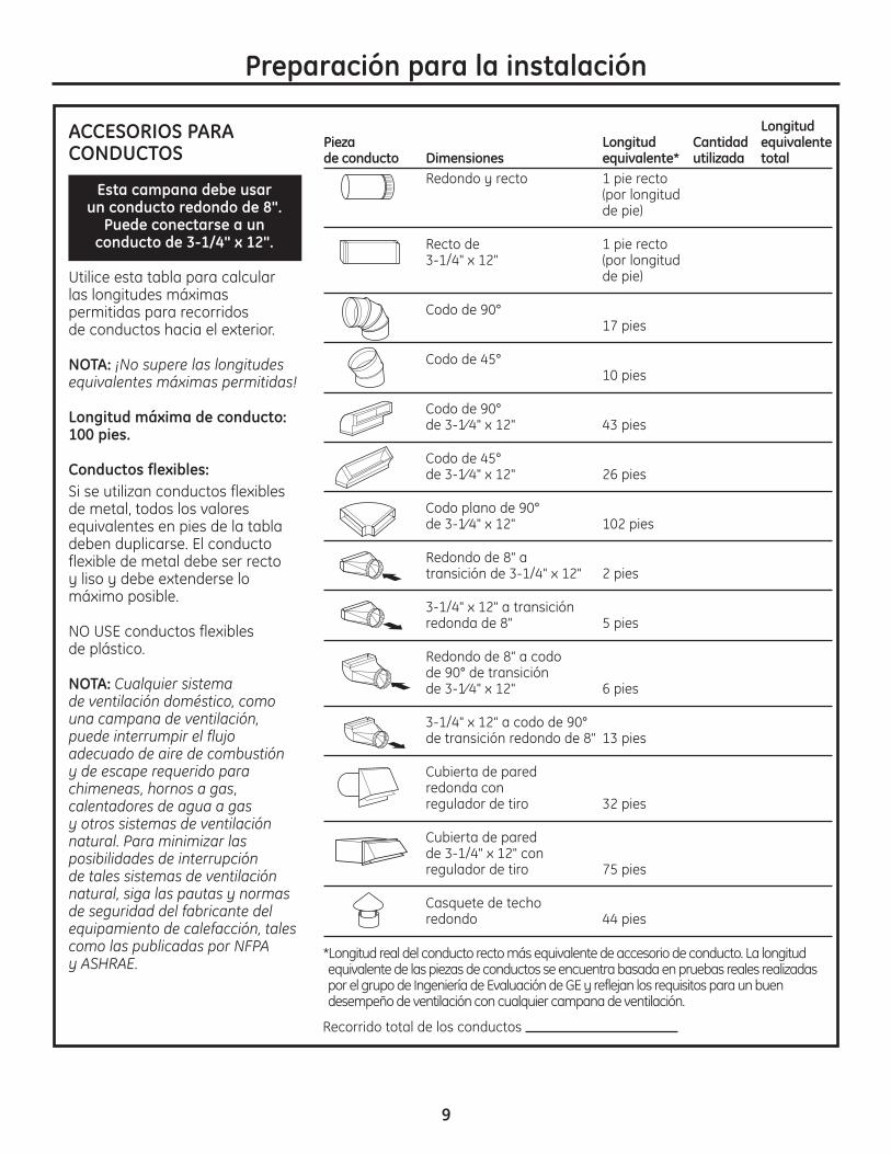
ACCESORIOS PARACONDUCTOS
Esta campana debe usar un conducto redondo de 8".
Puede conectarse a un conducto de 3-1/4" x 12".
Utilice esta tabla para calcular las longitudes máximaspermitidas para recorridos de conductos hacia el exterior.
NOTA: ¡No supere las longitudesequivalentes máximas permitidas!
Longitud máxima de conducto:100 pies.
Conductos flexibles:Si se utilizan conductos flexiblesde metal, todos los valoresequivalentes en pies de la tabladeben duplicarse. El conductoflexible de metal debe ser recto y liso y debe extenderse lomáximo posible.
NO USE conductos flexibles de plástico.
NOTA: Cualquier sistema de ventilación doméstico, comouna campana de ventilación,puede interrumpir el flujoadecuado de aire de combustión y de escape requerido parachimeneas, hornos a gas,calentadores de agua a gas y otros sistemas de ventilaciónnatural. Para minimizar lasposibilidades de interrupción de tales sistemas de ventilaciónnatural, siga las pautas y normasde seguridad del fabricante delequipamiento de calefacción, talescomo las publicadas por NFPA y ASHRAE.
LongitudPieza Longitud Cantidad equivalentede conducto Dimensiones equivalente* utilizada total
Redondo y recto 1 pie recto (por longitud de pie)
Recto de 1 pie recto 3-1/4" x 12" (por longitud
de pie)
Codo de 90° 17 pies
Codo de 45° 10 pies
Codo de 90°de 3-1⁄4" x 12" 43 pies
Codo de 45° de 3-1⁄4" x 12" 26 pies
Codo plano de 90° de 3-1⁄4" x 12" 102 pies
Redondo de 8" a transición de 3-1/4" x 12" 2 pies
3-1/4" x 12" a transiciónredonda de 8" 5 pies
Redondo de 8" a codode 90° de transiciónde 3-1⁄4" x 12" 6 pies
3-1/4" x 12" a codo de 90°de transición redondo de 8" 13 pies
Cubierta de pared redonda con regulador de tiro 32 pies
Cubierta de pared de 3-1/4" x 12" conregulador de tiro 75 pies
Casquete de techo redondo 44 pies
Recorrido total de los conductos
*Longitud real del conducto recto más equivalente de accesorio de conducto. La longitud equivalente de las piezas de conductos se encuentra basada en pruebas reales realizadas por el grupo de Ingeniería de Evaluación de GE y reflejan los requisitos para un buen desempeño de ventilación con cualquier campana de ventilación.

10
Preparación para la instalación
QUITE EL ENVOLTORIO
PRECAUCIÓN: Se guantes paraprotegerse de los bordes afilados.
• Quite las cubiertas de los conductos.• Quite la bolsa de piezas, el paquete
de instrucciones y otras piezas en cajas.• Quite y descarte adecuadamente el envoltorio
plástico de protección y otros materiales de empaque.
HERRAMIENTAS Y MATERIALESREQUERIDOS (NO SUMINISTRADOS)
Lápiz y cinta métrica
Alicates
Alicate pelacables
Tijeras para metal
Nivel de burbuja de aire
Cinta aislantede aluminio
Gafas de seguridad
Cable de 120V, 60Hz 15 o 20amperios de 2 hilos con circuitoderivado con conexión a tierra
Escalera
Sierra sable o serrucho de calar
Destornillador de estrella
Alivio de tensiónpara la caja deconexiones
Conducto de metalredondo de 8",longitud suficientepara la instalación
Martillo
Perforadora eléctrica con brocasde 3/16", de estrella N° 2 y cabeza plana
Linterna
Tapones de alambreaprobados por UL

CONTROLE LAS PIEZAS DE INSTALACIÓNUbique el paquete de hardware embalado con la campana y verifique los contenidos.
KIT DE RECIRCULACIÓN (Incluido)
11
Preparación para la instalación
Deflector de aire
Corte un orificiode acceso paracables de ½" dediámetro segúnsea necesario
8-1/4" hacia lalínea central delos orificios piloto
8-1/2"
FRENTE DE LA CAMPANA
Corte un orificio deacceso para cables de½" de diámetro según
sea necesario
Corte un orificiode acceso paracables de ½" dediámetro segúnsea necesario
Corte un orificiode acceso paracables de ½" dediámetro segúnsea necesario
Perfore orificios piloto de 3/16"de aprox. 1-1/2" de profundidaden los 4 lugares indicados
8-1/4" haciala línea central delos orificios piloto
10-5/16" hacia lalínea central delos orificios piloto
10-5/16" haciala línea centralde los orificiospiloto
31-14772Impreso en México 12-08 JR
PLANTILLA PARACAMPANA DE 36"
4 tornillospara madera
73 tornillos de sujeción de la campana
(70 requeridos, 3 extra)
Cubiertas del conducto
Filtro de carbón
C
Soporte del cielorraso
Soporte horizontal
Soportes verticalessuperiores (4)
Soportes verticalesinferiores (4)
Soportes de la cubiertadel conducto (2)
4 ganchos de la cubiertadel conducto
Plantilla
Filtro de acero inoxidable
D
B
E
A
A
B
C
D
E
PAQUETE DE HARDWAREUbique y cuente los tornillos
Superior
Inferior

12
DETERMINE LA ALTURA DE INSTALACIÓN• Se ofrecen cubiertas plegables para ocultar los
conductos que se extienden hasta el cielorraso.• Esta campana puede instalarse para una
operación de recirculación. Se incluye un kit de recirculación con la campana.
NOTA: La altura de instalación debe medirse desdela superficie de cocción hasta la parte plana de la sección inferior de la campana.Para un desempeño óptimo, la campana debeinstalarse a un mín. de 24" y un máx. de 30" sobre la superficie de cocción. La altura de instalación de la campana depende de la altura del cielorraso.
Preparación para la instalación
*Basado en una altura de mostrador de encimera de 36".
24" Min.*30" Max.*
36" Min.
* La altura de instalaciónexacta depende de la altura del cielorraso.
PV977 – IslaCubierta de conducto superior 29.92Cubierta de conducto inferior 25.98
Mostrador hasta la altura de la campanaAltura *Altura de instalación *Altura de instalación
real del posible CON posible CON cielorraso VENTILACIÓN RECIRCULACIÓN
7' 11" 24" 24"8' 0" 24" a 25" 24" a 25"8' 1" 24" a 26" 24" a 26"8' 2" 24" a 27" 24" a 27"8' 3" 24" a 28" 24" a 28"8' 4" 24" a 29" 24" a 29"8' 5" 24" a 30" 24" a 30"8' 6" 24" a 30" 24" a 30"8' 7" 24" a 30" 24" a 30"8' 8" 24" a 30" 24" a 30"8' 9" 24" a 30" 24" a 30"
8' 10" 24" a 30" 24" a 30"8' 11" 24" a 30" 24" a 30"9' 0" 24" a 30" 24" a 30"9' 1" 24" a 30" 24" a 30"9' 2" 24" a 30" 24" a 30"9' 3" 24" a 30" 24" a 30"9' 4" 24" a 30" 24" a 30"9' 5" 26" a 30" 24" a 30"9' 6" 26" a 30" 24" a 30"9' 7" 27" a 30" 24" a 30"9' 8" 28" a 30" 24" a 30"9' 9" 29" a 30" 24" a 30"
9' 10" 30" 25" a 30"9' 11" 26" a 30"10' 0" 27" a 30"10' 1" 28" a 30"10' 2" 29" a 30"10' 3" 30"

13
Planifique la ubicación de la campana y del conducto• Utilice una plomada para verificar la ubicación.
El mostrador de encimera/la estufa debajo de la campana deben centrarse respecto de la campana.
• La campana debe extenderse más allá de losbordes frontal y trasero del aparato de cocción.
• El conducto del cielorraso debe centrarse sobre la estufa.
CONSTRUYA EL SOPORTE DEL CIELORRASO
Preparación para la instalación
Visión superior – vigas del cielorraso paralelas al frente de la campana
Espacio paraviga de 16"
8-1/4" Conducto de 8”
Frente de la
campana
Soportes de maderadel armazón cruzadode 2 x 4
Contorno de la estufaAlinee el conducto con
el centro de la estufa
Estructura del soporte de cielorraso• En la ubicación de la campana, instale un armazón
cruzado entre las vigas como se indica. (Se requierensoportes de madera de 2 x 4 para sostener el peso de la campana.)
• Coloque el armazón cruzado en el cielorraso de modo que se ajuste a la estructura existente.
• Las vigas del cielorraso serán como uno de lossiguientes ejemplos.
EJEMPLO A
Cielorraso
Línea centraldel conducto de la campana
Estufa
Mostrador de encimera
13-13/16"
Visión lateral
Alinear conel centro de la estufa
Instale el armazón cruzado en forma simétrica sobrela línea central del conducto/estufa
10-5/16"
27-5/8"
3-1/8"
Cubiertas del conducto
14
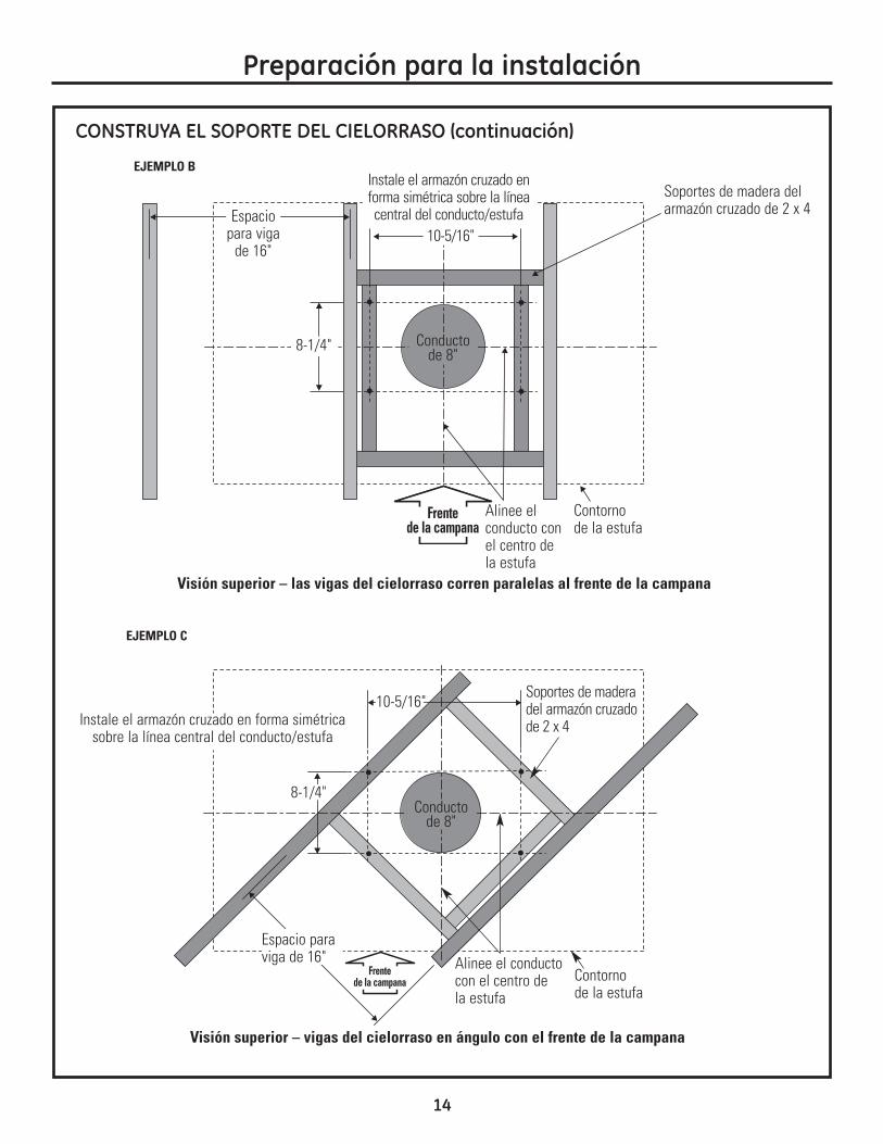
Visión superior – las vigas del cielorraso corren paralelas al frente de la campana
Visión superior – vigas del cielorraso en ángulo con el frente de la campana
Preparación para la instalación
CONSTRUYA EL SOPORTE DEL CIELORRASO (continuación)
Espaciopara viga
de 16"
8-1/4" Conductode 8"
Soportes de madera delarmazón cruzado de 2 x 4
Contorno de la estufa
Alinee el conducto con el centro de la estufa
Espacio paraviga de 16"
Conductode 8"
Contorno de la estufa
Alinee el conductocon el centro de la estufa
EJEMPLO B
EJEMPLO C
10-5/16"
Instale el armazón cruzado enforma simétrica sobre la líneacentral del conducto/estufa
Soportes de maderadel armazón cruzadode 2 x 4Instale el armazón cruzado en forma simétrica
sobre la línea central del conducto/estufa
8-1/4"
10-5/16"
Frente de la campana
Frente de la campana

15
CONSTRUYA EL SOPORTE DEL CIELORRASO (continuación)
Preparación para la instalación
Conductos para instalaciones con ventilación haciael exterior• Utilice el recorrido de conductos más corto y más
recto posible. Para un desempeño satisfactorio, el recorrido de los conductos no debe superar unalongitud equivalente a los 100 pies para ningunaconfiguración de conductos.
• Consulte la tabla “Accesorios de conductos” para calcular la longitud máxima permisible para recorridos de conductos hacia el exterior.
• Esta campana de ventilación debe utilizar unconducto rígido redondo de 8".
• Instale el conducto doméstico para que corra en forma horizontal entre las vigas del cielorraso o en forma recta a través del techo.
Finalice el cielorraso• Finalice la superficie del cielorraso. Asegúrese
de marcar la ubicación de las vigas del cielorraso y del armazón cruzado. Controle que el cielorrasoesté nivelado; utilice cuñas si fuese necesario.
• Fije cada bloque de 2 x 4 con por lo menos cuatro(4) tornillos para madera N°10 de 3” de longitud (no provistos). Utilice un total de 8 tornillos paramadera para los dos soportes.
• El armazón cruzado debe estar precisamentealineado para garantizar una posición correctade la campana.
• El armazón cruzado debe estar nivelado en todaslas direcciones. Controle con un nivel de burbuja y ajuste si hiciera falta.
IMPORTANTE: La estructura del cielorraso debepoder soportar el peso de la campana(aproximadamente 200 libras) y las cargas decontacto involuntarias ejercidas por el usuario. El armazón de la campana tendrá el soporte de un armazón cruzado de 2 x 4.
Armazón cruzadode 2 x 4 mín.
Viga delcielorraso
8-1/4"
Conductode 8"
Viga del cielorraso
10-5/16"
2 x 4Ventilación recta
a través del cielorraso
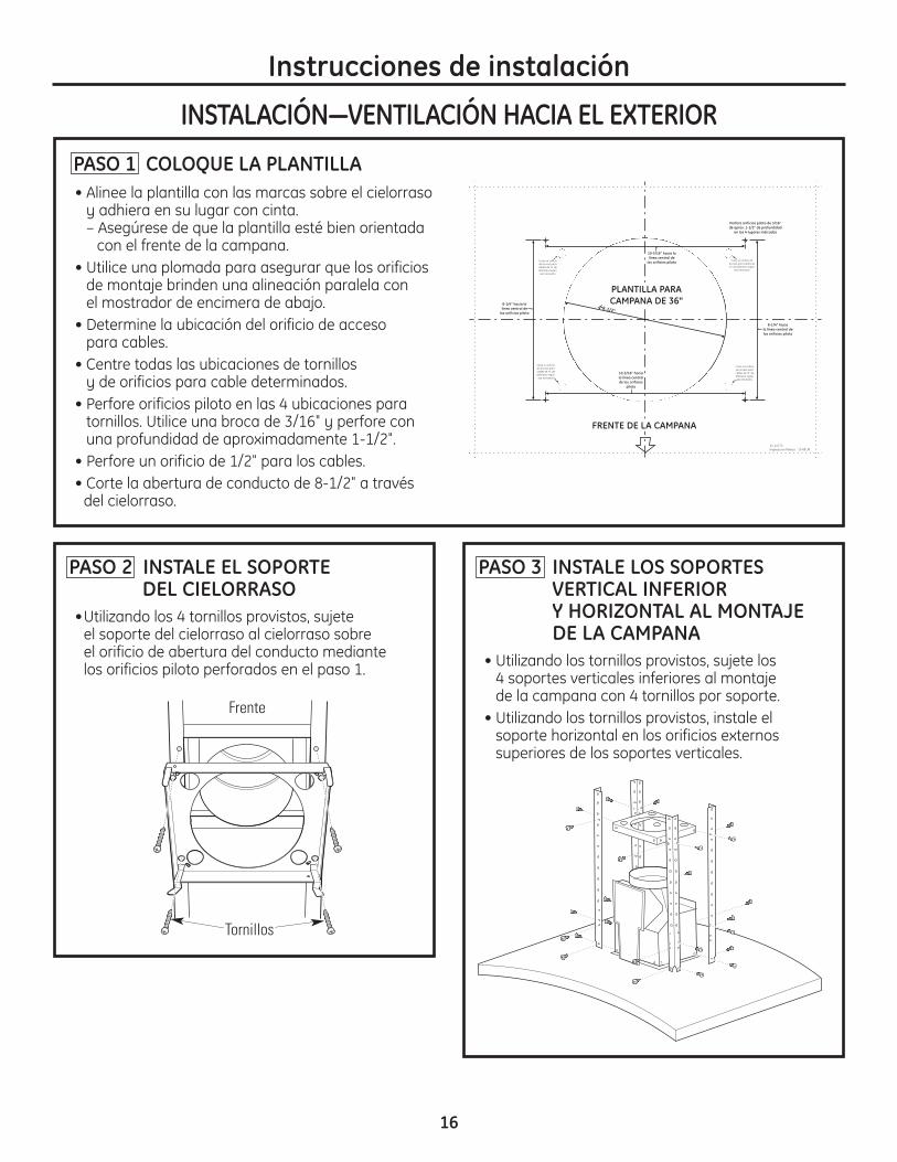
16
• Alinee la plantilla con las marcas sobre el cielorrasoy adhiera en su lugar con cinta.– Asegúrese de que la plantilla esté bien orientada
con el frente de la campana.• Utilice una plomada para asegurar que los orificios
de montaje brinden una alineación paralela con el mostrador de encimera de abajo.
• Determine la ubicación del orificio de acceso para cables.
• Centre todas las ubicaciones de tornillos y de orificios para cable determinados.
• Perfore orificios piloto en las 4 ubicaciones paratornillos. Utilice una broca de 3/16" y perfore conuna profundidad de aproximadamente 1-1/2".
• Perfore un orificio de 1/2" para los cables.• Corte la abertura de conducto de 8-1/2" a través
del cielorraso.
PASO 1 COLOQUE LA PLANTILLA
Instrucciones de instalación
INSTALACIÓN—VENTILACIÓN HACIA EL EXTERIOR
PASO 2 INSTALE EL SOPORTE DEL CIELORRASO
•Utilizando los 4 tornillos provistos, sujete el soporte del cielorraso al cielorraso sobre el orificio de abertura del conducto mediante los orificios piloto perforados en el paso 1.
PASO 3 INSTALE LOS SOPORTESVERTICAL INFERIOR Y HORIZONTAL AL MONTAJE DE LA CAMPANA
• Utilizando los tornillos provistos, sujete los 4 soportes verticales inferiores al montaje de la campana con 4 tornillos por soporte.
• Utilizando los tornillos provistos, instale elsoporte horizontal en los orificios externossuperiores de los soportes verticales.
Corte un orificiode acceso paracables de ½" dediámetro segúnsea necesario
8-1/4" hacia lalínea central delos orificios piloto
8-1/2"
FRENTE DE LA CAMPANA
Corte un orificio deacceso para cables de½" de diámetro según
sea necesario
Corte un orificiode acceso paracables de ½" dediámetro segúnsea necesario
Corte un orificiode acceso paracables de ½" dediámetro segúnsea necesario
Perfore orificios piloto de 3/16"de aprox. 1-1/2" de profundidaden los 4 lugares indicados
8-1/4" haciala línea central delos orificios piloto
10-5/16" hacia lalínea central delos orificios piloto
10-5/16" haciala línea centralde los orificiospiloto
31-14772Impreso en México 12-08 JR
PLANTILLA PARACAMPANA DE 36"
Tornillos
Frente

17
Instrucciones de instalación
PASO 5 INSTALE LOS SOPORTESVERTICALES SUPERIORES EN EL MONTAJE DE LA CAMPANA
• Determine qué cantidad de los soportes verticalessuperiores tendrán que estar sobre los soportesinferiores para alcanzar la altura del armazónestablecida en el paso 4 de esta instalación.
• Utilizando los tornillos provistos, sujete los 4soportes verticales superiores a los soportesverticales inferiores en la posición determinadapara la altura del armazón. Los soportesverticales superiores se montan en el lado externode los soportes inferiores.
PASO 4 DETERMINE LA ALTURA DEL ARMAZÓN
•Mida la alturaexacta delcielorraso.
•Consulte la altura exactadel cielorrasorequerida en la tabla de la página 12.
•Use esta fórmulapara determinarla altura delarmazón: A-(B+C+D) = Altura del armazón E, dondeA es la altura delcielorraso, B es laaltura del mostradorde encimera, C es la altura determinadapor la tabla de la página 12, D es la altura de lacampana medidadesde la porcióninferior recta hasta la parte superiorcentral.
24" Min.*30" Max.*
36" Min.
Altura delarmazón
2-3/8"
Altura delcielorraso
E
EA
B
DC
*Ver la tabla de la página 12.

Instrucciones de instalación
INSTALACIÓN—VENTILACIÓN HACIA EL EXTERIOR
PASO 6 CORTE EL CONDUCTO CON LA LONGITUD PARA UNAINSTALACIÓN VENTILADA
• Mida desde la abertura de escape de la campanahasta la parte superior de los soportes comopuede verse en la figura.
• Reste la longitud del conducto que sobresalga a través del cielorraso.
• Corte el conducto de 8" con la longitud apropiada.Fije el conducto del cielorraso utilizando cinta de aluminio y tornillos.
18
PASO 7 INSTALE EL MONTAJE DE LA CAMPANA EN EL SOPORTEDEL CIELORRASO
ADVERTENCIA: Se necesitan dos personas para levantar y colocar la campanasobre el soporte. • Levante el montaje de la campana hasta
el soporte del cielorraso. Con cuidado coloque el conducto recién montado sobre la abertura de escape del montaje de la campana. Losganchos del soporte del cielorraso se trabarándentro de las aberturas grandes de los soportesverticales superiores.
• Utilizando los tornillos provistos, sujete lossoportes verticales superiores al soporte del cielorraso, 4 tornillos por lado, hasta alcanzarun total de 16 tornillos.
• Selle el conducto con cinta aislante de aluminio.
Soporte delcielorraso
Ganchos
Longitud delconducto necesariamenos la longitudque sobresale através del cielorraso.
Selle con cintaaislante de
aluminio

PASO 9 INSTALE LOS SOPORTES DE LA CUBIERTA DEL CONDUCTO
• Sujete los soportes de la cubierta del conducto a los costados de los soportes horizontales y de cielorraso usando 4 tornillos por soporte.
Instrucciones de instalación
PASO 8 CONECTE LOS ELEMENTOSELÉCTRICOS
Verifique que la energía esté cortada en la fuente.
ADVERTENCIA: Si el cableadodoméstico no cuenta con un cable de 2 hilos conconexión a tierra, un instalador debe realizar unaconexión a tierra. Cuando el cableado doméstico es de aluminio, asegúrese de usar un compuestoantioxidante y conectores de aluminio a cobreaprobados por UL.• Quite los 6 tornillos de la tapa de la caja
de conexiones y el calado sobre la parte superiorizquierda.
• Asegure el cableado doméstico a la caja deconexiones con un alivio de tensión (no provisto).
• Conecte el cable blanco al cable blanco del circuitoderivado.
• Conecte el cable negro al cable negro del circuitoderivado.
• Conecte el cable verde/amarillo al cable verde delcircuito derivado o al cable de conexión a tierra.
• Ajuste todas las conexiones con tapones de alambre sobre cada conector eléctrico.
• Empuje los cables dentro de la caja de conexionesy vuelva a colocar la tapa. Verifique que los cablesno sufran pellizcos.
• Ajuste la tapa de la caja de conexiones con los 6 tornillos originales.
Tapa de la cajade conexiones
19
Tornillos
Soporte delcielorraso
Soportehorizontal
CaladoSoporte de la cubierta
del conducto

Instrucciones de instalación
PASO 10 INSTALE LAS CUBIERTAS DEL CONDUCTO (cont.)
• Usando los tornillos provistos, fije las cubiertas del conducto inferiores al montaje de la campanadesde la parte inferior de la campana.
PASO 11 INSTALE EL FILTRO DE GRASAMETÁLICO
• Quite la película protectora del filtro de grasa.NOTA: No se necesita el filtro de carbón para estainstalación.
• Coloque las lengüetas del extremo del filtro dentrode las ranuras del lado izquierdo de la aberturadel filtro. Levante el lado derecho del filtro y presione ligeramente hasta que el filtro se trabeen su lugar. Verifique que la traba del filtro se encuentre en la posición cerrada paraasegurar el filtro.
• Para quitar el filtro, tire de la traba del filtro haciaabajo.
INSTALACIÓN—VENTILACIÓN HACIA EL EXTERIORPASO 10 INSTALE LAS CUBIERTAS
DEL CONDUCTOIMPORTANTE: Se necesitan dos personas parainstalar las cubiertas del conducto.NOTA: Si va a instalar esta campana para unaoperación de recirculación, coloque las cubiertas del conducto sobre la campana con las ranuras de ventilación en la parte superior. Si la campana se ventila hacia el exterior, los orificios debencolocarse en la parte inferior.• Quite la película protectora de todas las cubiertas
del conducto.• Coloque una cubierta del conducto superior sobre
la parte trasera del montaje del soporte. Laslengüetas de los extremos de la cubierta delconducto se deslizarán dentro de una ranura del soporte. Cuando las 6 lengüetas de la cubiertadel conducto se encuentran en las ranuras de losdos soportes de la cubierta del conducto, deslice la cubierta hacia arriba para que quede colocada en el gancho a resorte del soporte.
• Coloque un gancho de la cubierta del conducto en la parte inferior de la cubierta del conducto inferior,trabando el gancho en su lugar. Repita en el otro lado.
• Baje la cubierta del conducto dentro del espacio de la campana, con cuidado de sostener el ganchoen su lugar mientras baja la cubierta del conductosobre el montaje de la campana.
• Coloque la cubierta del conducto inferior frontal enel espacio de la campana trabándola en el ganchode la cubierta del conducto de la cubierta trasera.
• Coloque un gancho de la cubierta del conducto enla parte superior de cada lado donde se juntan lascubiertas del conducto frontal y trasera. Estomantendrá unidas las cubiertas trasera y frontal.
Gancho de la cubierta del conducto
20
Gancho a resorte del soportede cubierta del conducto
Cubierta del conducto izquierdo

21
• Alinee la plantilla con las marcas sobre el cielorrasoy adhiera en su lugar con cinta.– Asegúrese de que la plantilla esté bien orientada
con el frente de la campana. • Utilice una plomada para asegurar que los orificios
de montaje brinden una alineación paralela con el mostrador de encimera de abajo.
• Determine la ubicación del orificio de acceso paracables.
• Centre todas las ubicaciones de tornillos y de orificios para cable determinados.
• Perfore orificios piloto en las 4 ubicaciones paratornillos. Utilice una broca de 3/16" y perfore conuna profundidad de aproximadamente 1-1/2".
• Perfore un orificio de 1/2" para los cables.
PASO 1 COLOQUE LA PLANTILLA
Instrucciones de instalación
INSTALACIÓN—RECIRCULACIÓN
NOTA: No corte la abertura del conducto indicada en la plantilla para esta instalación con recirculación.
Corte un orificiode acceso paracables de ½" dediámetro segúnsea necesario
8-1/4" hacia lalínea central delos orificios piloto
8-1/2"
FRENTE DE LA CAMPANA
Corte un orificio deacceso para cables de½" de diámetro según
sea necesario
Corte un orificiode acceso paracables de ½" dediámetro segúnsea necesario
Corte un orificiode acceso paracables de ½" dediámetro segúnsea necesario
Perfore orificios piloto de 3/16"de aprox. 1-1/2" de profundidaden los 4 lugares indicados
8-1/4" haciala línea central delos orificios piloto
10-5/16" hacia lalínea central delos orificios piloto
10-5/16" haciala línea centralde los orificiospiloto
31-14772Impreso en México 12-08 JR
PLANTILLA PARACAMPANA DE 36"
PASO 3 INSTALE EL MONTAJE DEL SOPORTE DEL CIELORRASO Y DEFLECTOR
•Utilizando los 4 tornillos para madera provistos,sujete el soporte del cielorraso utilizando los orificiospiloto perforados en el paso 1.
Tornillos
PASO 2 INSTALE EL DEFLECTOR DE AIRE DENTRO DEL SOPORTE DEL CIELORRASO
•Coloque el soporte del cielorraso sobre unasuperficie firme, con el lado del gancho hacia arriba.
•Coloque el deflector de aire en el soporte delcielorraso, con la abertura del conducto haciaarriba y uno de los lados abiertos hacia lo que seráel frente del montaje de la campana. Laslengüetas del deflectorquedarán hacia el ladoexterior del soporte delcielorraso.
•Utilizando los 2 tornillosprovistos, fije laslengüetas del deflectoral soporte del cielorraso.
Frente
PASO 4 INSTALE LOS SOPORTESVERTICAL INFERIOR Y HORIZONTAL EN EL MONTAJEDE LA CAMPANA
• Utilizando los tornillos provistos, sujete los 4 soportes verticales inferiores al montaje de la campana con 4 tornillos por soporte.
• Utilizando los tornillos provistos, instale elsoporte horizontal en los segundos orificiosexternos de los soportes verticales.

PASO 5 DETERMINE LA ALTURA DEL ARMAZÓN
•Mida la alturaexacta delcielorraso.
•Consulte la altura exactadel cielorrasorequerida en la tabla de la página 12.
•Use esta fórmulapara determinarla altura delarmazón:A-(B+C+D) = Altura del armazón E, dondeA es la altura delcielorraso, B es laaltura del mostradorde encimera, C es la altura determinadapor la tabla de la página 12, D es la altura de lacampana medidadesde la porcióninferior recta hasta la parte superiorcentral.
24" Min.*30" Max.*
36" Min.
Altura delarmazón
2-3/8"
Altura delcielorraso
22
Instrucciones de instalación
INSTALACIÓN—RECIRCULACIÓN
EA
B
DC
PASO 6 INSTALE EL SOPORTE VERTICALSUPERIOR
• Utilizando los tornillos provistos, sujete los 4 soportes verticales superiores a los soportesverticales inferiores en la posición determinadapara la altura del armazón. Los soportes verticalessuperiores se montan en el lado externo de lossoportes inferiores.
*Ver la tabla de la página 12.
E

23
Instrucciones de instalación
PASO 7 DETERMINE LA LONGITUD DEL CONDUCTO E INSTÁLELO
• Mida desde la abertura de escape de la campanahasta la parte superior de los soportes comopuede verse en la figura.
• Reste la altura del deflector de aire.• Corte el conducto de 8" con la longitud apropiada.
Fije el deflector de aire utilizando cinta dealuminio y tornillos.
Longitud delconducto necesariamenos la longitudque sobresale através del cielorraso.
PASO 8 INSTALE EL MONTAJE DE LA CAMPANA EN EL SOPORTEDEL CIELORRASO
ADVERTENCIA: Se necesitan dospersonas para levantar y colocar la campanasobre el soporte.• Con cuidado levante el montaje de la campana
hasta el soporte del cielorraso. Los ganchos delsoporte del cielorraso se trabarán dentro de lasaberturas de los soportes verticales.
• Deslice el conducto sobre la abertura de escape.• Utilizando los tornillos provistos, sujete los
soportes verticales superiores al soporte delcielorraso, 2 tornillos por lado, hasta alcanzar un total de 16 tornillos.
• Selle el conducto de aire a la abertura de escapeutilizando cinta aislante de aluminio.
Soporte delcielorraso
Deflector de aire
Ganchos
Selle concinta aislantede aluminio

24
Instrucciones de instalación
INSTALACIÓN—RECIRCULACIÓNPASO 9 CONECTE LOS ELEMENTOS
ELÉCTRICOSVerifique que la energía esté cortada en la fuente.
ADVERTENCIA: Si el cableadodoméstico no cuenta con un cable de 2 hilos conconexión a tierra, un instalador debe realizar unaconexión a tierra. Cuando el cableado doméstico es de aluminio, asegúrese de usar un compuestoantioxidante y conectores de aluminio a cobreaprobados por UL.• Quite los 6 tornillos de la tapa de la caja
de conexiones y el calado sobre la parte superior izquierda.
• Asegure el cableado doméstico a la caja deconexiones con un alivio de tensión (no provisto).
• Conecte el cable blanco al cable blanco del circuitoderivado.
• Conecte el cable negro al cable negro del circuitoderivado.
• Conecte el cable verde/amarillo al cable verde delcircuito derivado o al cable de conexión a tierra.
• Ajuste todas las conexiones con tapones de alambre sobre cada conector eléctrico.
• Empuje los cables dentro de la caja de conexionesy vuelva a colocar la tapa. Verifique que los cablesno sufran pellizcos.
• Ajuste la tapa de la caja de conexiones con los 6 tornillos originales.
Tapa de la cajade conexiones
Calado
PASO 10 INSTALE LOS SOPORTES DE LA CUBIERTA DEL CONDUCTO
• Sujete los soportes de la cubierta del conducto a los costados de los soportes horizontales y de cielorraso usando 4 tornillos por soporte.
Tornillos
Soporte delcielorraso
Soportehorizontal
Soporte de la cubierta
del conducto

Instrucciones de instalación
25
PASO 11 INSTALE LAS CUBIERTAS DEL CONDUCTO
IMPORTANTE: Se necesitan dos personas parainstalar las cubiertas del conducto.NOTA: Si va a instalar esta campana para unaoperación de recirculación, coloque las cubiertasdel conducto sobre la campana con las ranuras de ventilación en la parte superior. Si la campana se ventila hacia el exterior, los orificios debencolocarse en la parte inferior.• Quite la película protectora de todas las cubiertas
del conducto.• Coloque una cubierta del conducto sobre la parte
trasera del montaje del soporte. Las lengüetas de los extremos de la cubierta del conducto se deslizarán dentro de una ranura del soporte.Cuando las 6 lengüetas de la cubierta delconducto se encuentran en las ranuras de los dos soportes de la cubierta del conducto, deslicela cubierta hacia arriba para que quede colocadaen el gancho a resorte del soporte.
Cubierta delconducto izquierdo
Gancho a resorte del soportede cubierta del conducto
PASO 11 INSTALE LAS CUBIERTAS DEL CONDUCTO (cont.)
• Coloque un gancho de la cubierta del conductoen la parte inferior de la cubierta del conductoinferior, trabando el gancho en su lugar. Repita en el otro lado.
• Baje la cubierta del conducto dentro del espaciode la campana.
• Coloque la cubierta del conducto inferior frontalen el espacio de la campana trabándola en elgancho de la cubierta del conducto de la cubiertatrasera.
• Coloque un gancho de la cubierta del conductosobre cada lado donde se juntan las cubiertas del conducto frontal y trasera. Esto mantendráunidas las cubiertas trasera y frontal.
Gancho de la cubierta del conducto
• Usando los tornillos provistos, fije las cubiertas del conducto inferiores al montaje de la campanadesde la parte inferior de la campana.

26
Instrucciones de instalación
INSTALACIÓN—RECIRCULACIÓNPASO 12 INSTALE LOS FILTROSFiltro de carbónIntroduzca el filtro de carbón dentro de la abertura.Presione la traba sobre ambos lados hacia el centro y sujete la brida.
Filtro de grasa metálico• Quite la película protectora del filtro de grasa.• Coloque las lengüetas del extremo del filtro
dentro de las ranuras del lado izquierdo de laabertura del filtro. Levante el lado derecho delfiltro y presione ligeramente hasta que el filtro se trabe en su lugar. Verifique que la traba delfiltro se encuentre en la posición cerrada paraasegurar el filtro.
• Para quitar el filtro, tire de la traba del filtro hacia abajo.

27
Antes de llamar al servicio técnico…
Consejos para identificación y solución de problemas¡Ahorre tiempo y dinero! Lea la siguiente tabla primero y quizás no necesite llamar al servicio técnico.
Problema Causas posibles Qué hacerEl ventilador/la luz no El fusible puede haberse • Cambie los fusibles o reconfigure el interruptor funcionan cuando se quemado o el interruptor de de circuitos. presionan los botones circuitos puede haber saltado.
El ventilador no funciona El conector del ventilador está •Desconecte la electricidad hacia la unidad. Quitecuando se presiona el suelto o no se encuentra los filtros y observe el ventilador. Si el enchufe botón + o – del ventilador enchufado dentro de su conector del conector del ventilador está suelto o si ve o el botón MEMORY/OFF correspondiente. el conector colgando, el instalador no lo enchufó (memoria/apagado) firmemente. Ver las Instrucciones de instalación
para la ubicación del enchufe y sobre cómo enchufar el conector.
Ruido de flujo de aire Tamaño de conducto incorrecto •Esta campana requiere un conducto de 8" y unamuy elevado o anormal utilizado en la instalación. longitud máxima de conducto de 100 pies
equivalentes para funcionar correctamente. Utilizarconductos más pequeños o longitudes equivalentes mayores provocará una ventilación inadecuada. Lostécnicos de GE no pueden corregir este problemasi hay una instalación inadecuada.
El ventilador no hace Obstrucciones en el conducto. •Verifique que no haya obstrucciones en la ventilación.circular aire o desplaza Controle que la cubierta de pared o casquete de techo desplaza el aire más tengan una hoja o puerta.despacio que lo normal La hoja del regulador de tiro •Asegúrese de que el regulador de tiro se muevay/o hace ruido de flujo de la cubierta de pared libremente. Las hojas del regulador de tiro puedende aire elevado o anormal o casquete de techo puede darse vuelta y no se abrirán por completo cuando
estar cerrada. esto suceda. Ajústela con la posición original.
El filtro de grasa metálico •Limpie el filtro de grasa metálico y vuelva a colocar y el filtro de carbón (si lo el filtro de carbón (si lo hubiera). Ver Cuidadohubiera) pueden estar sucios. y limpieza de la campana de ventilación.
Los controles de la Error en el circuito lógico. •Desconecte la electricidad de la campana campana no funcionan reconfigurando el interruptor de circuitos. Espere 30correctamente segundos para que los controles vuelvan a configurarse.
Falla temprana Cambiar las bombillas con las •Cambie las bombillas usando guantes para evitarde la bombilla manos desnudas. el contacto de aceites de la piel con las bombillas.
•El vataje de la bombilla es muy elevado. Utiliceel vataje correcto.
La campana no funciona La característica de memoria •Siga los procedimientos para configurar el botón cuando se presiona el no se ha configurado. Esto MEMORY/OFF. Ajuste las configuraciones delbotón MEMORY/OFF. es normal. ventilador y de luz de acuerdo con sus preferencias. Todos los collarines ubicados alrededor delos botones se encuentraniluminados.
Apoyo al ClienteSolucionar Problem
asInstrucciones de O
peraciónInstrucciones de Seguridad
Cuidado y Limpieza

28
Antes de llamar al servicio técnico…
Consejos para identificación y solución de problemas¡Ahorre tiempo y dinero! Lea la siguiente tabla primero y quizás no necesite llamar al servicio técnico.
Problema Causas posibles Qué hacerEl ventilador se encendió Se encuentra activado el sensor •Esto es normal cuando las temperaturas debajo desolo y se encuentra en la de calor. la campana superan los límites del sensor de calor. configuración MED Quite la fuente de calor debajo de la campana(media). La configuración o espere a que la campana se enfríe a niveles de ventilador puede apropiados. La campana se apagará puede ajustarse pero no automáticamente o volverá a su configuración apagarse (OFF). original una vez que el sensor detecte que la
temperatura ha alcanzado una condición segura.
El collarín ubicado El botón de presión puede estar •Controle el botón de presión afectado y verifique ubicado alrededor trabado. que no esté trabado. Llame al servicio técnicodel botón de presión si continúa el problema.no se ilumina cuandose presiona.
Dos o más collarines Dos o más botones de presión •Controle los botones de presión afectadosubicados alrededor de pueden estar trabados. y verifique que no estén trabados. Llame al servicio de los botones de presión técnico si continúa el problema. no se iluminan cuando se presionan.
Las presiones Esto es normal. Es una •No se requiere una acción.secuenciales a los característica de la campanabotones LIGHT (luz) o FAN que los botones LIGHT y FAN (ventilador) cambian la se desplacen entreconfiguración de baja configuraciones para podera OFF (apagado), a la programar fácilmente los configuración más alta, controles en la configuracióna OFF, a la configuración deseada.
Apoy
o al
Clie
nte
Solu
cion
ar P
robl
emas
Inst
rucc
ione
s de
Ope
raci
ónIn
stru
ccio
nes
de S
egur
idad
Cuid
ado
y Li
mpi
eza

29
Garantía de GE campanas de ventilación.
Por el período de: GE reemplazará:
Un año Cualquier parte de la estufa de cubierta a gas que falle debido a defectos en los materialesA partir de la fecha o en la fabricación. Durante esta lgarantía limitada de un año, GE también proporcioná, all labor de la compra original sin costo alguno, toda la mano de obra y el servicio relacionado para reemplazar partes defectuosas.
■ Viajes de servicio a su casa para mostrarle cómo funciona el equipo.
■ Instalación o entrega inapropriada, o mantenimiento impropio.
■ Fallo del producto resultante de modificaciones alproducto o debido a uso incorrecto incluyendo noproporcionar mantenimiento razonable y necesario.
■ Reemplazo de fusibles de la casa o reajuste del sistemade circuitos.
■ Daño al producto causado por accidentes, incendios,inundaciones o actos de la naturaleza de fuerza mayor.
■ Daños incidentales o consecuenciales causados pordefectos posibles con este aparato.
■ Daños causados después de la entrega.
■ Producto no accesible para facilitar el servicio requerido.
Lo que no está cubierto por GE:
Todos los servicios de garantía los proporcionan nuestros Centrosde Reparación de Fábrica o nuestros técnicos Customer Care®
autorizados. Para concertar una cita de reparación, en línea,visítenos en ge.com, o llame al 800.GE.CARES (800.432.2737).Cuando llame para solicitar servicio, por favor tenga a mano el número de serie y el número de modelo.
Peque aquí su recibo. Se requiere facilitar prueba
de la fecha de compra original para obtener un servicio
bajo la garantía.
Esta garantía se extiende al comprador original y cualquier comprador posterior de productos comprados para uso residencial dentro des Estados Unidos. Si el producto está situado en un área que no dispone de servicio por parte de un proveedor de servicio autorizado de GE, podría tener que hacerse cargo de los costes de envíoo bien podría solicitársele que lleve el producto a una centro de servicio de GE autorizado para realizar lareparación. En Alaska, la garantía excluye el costo de envío o las visitas de servicio a su casa.
Algunos estados no permiten la exclusión o las limitaciones de daños incidentales o consecuenciales. Esta garantíada derechos legales específicos, y usted podría tener otros derechos que variarán de estado a estado. Para sabercuáles son sus derechos legales, consulte a la oficina de asuntos del consumidor local o la oficina del Prucurador(Attorney General) en su localidad.
Garante: General Electric Company. Louisville, KY 40225
EXCLUSIÓN DE GARANTÍAS IMPLÍCITAS—Su único y exclusivo derecho es la reparación del producto, tal y como se indica en esta Garantía limitada. Cualquier garantía implícita, incluyendo las garantíasimplícitas de comerciabilidad o adecuación para un fin determinado, están limitadas a un año o el período de tiempo más breve permitido por la ley.
Apoyo al ClienteSolucionar Problem
asInstrucciones de O
peraciónInstrucciones de Seguridad
Cuidado y Limpieza

30
Apoyo al consumidor.
Página Web de GE Appliances ge.com¿Tiene alguna pregunta sobre su electrodoméstico? ¡Pruebe la página Web de GE Appliances, cualquier día del año! Para mayor conveniencia y servicio más rápido, ya puede descargar los Manuales de los Propietarios, pedir piezas o incluso hacer una cita en línea para que vengan a realizar una reparación.
Solicite una reparación ge.comEl servicio de expertos GE está a tan sólo un paso de su puerta. ¡Entre en línea y solicite su reparación cuandole venga cualquier día del año! O llame al 800.GE.CARES (800.432.2737) durante horas normales de oficina.
Real Life Design Studio (Estudio de diseño para la vida real) ge.comGE apoya el concepto de Diseño Universal—productos, servicios y ambientes que pueden usar gente de todaslas edades, tamaños y capacidades. Reconocemos la necesidad de diseñar para una gran gama de habilidadesy dificultades físicas y mentales. Para más detalles cobre las aplicaciones de GE Diseño Universal, incluyendoideas de diseño para la cocina para personas con discapacidades, mire nuestra página Web hoy mismo. Para personas con dificultades auditivas, favor de llamar al 800.TDD.GEAC (800.833.4322).
Garantías ampliadas ge.comCompre una garantía ampliada y obtenga detalles sobre descuentos especiales disponibles mientras su garantíaestá aún activa. Puede comprarla en línea en cualquier momento, o llamar al 800.626.2224 durante horasnormales de oficina. GE Consumer Home Services estará aún ahí cuando su garantía termine.
Piezas y accesorios ge.comAquellos individuos con la calificación necesaria para reparar sus propios electrodomésticos pueden pedir que se les manden las piezas o accesorios directamente a sus hogares (aceptamos las tarjetas VISA, MasterCard y Discover). Haga su pedido en línea hoy, 24 horas cada día o llamar por teléfono al 800.626.2002 durante horas normales de oficina.
Las instrucciones descritas en este manual cubren los procedimientos a seguir por cualquier usuario.Cualquier otra reparación debería, por regla general, referirse a personal calificado autorizado. Debeejercerse precaución ya que las reparaciones incorrectas pueden causar condiciones de funcionamientoinseguras.
Póngase en contacto con nosotros ge.comSi no está satisfecho con el servicio que recibe de GE, póngase en contacto con nosotros en nuestra páginaWeb indicando todos los detalles así como su número de teléfono o escríbanos a:
General Manager, Customer RelationsGE Appliances, Appliance ParkLouisville, KY 40225
Registre su electrodoméstico ge.com¡Registre su nuevo electrodoméstico en línea—cuando usted prefiera! El registrar su producto a tiempo le proporcionará, si surgiera la necesidad, una mejor comunicación y un servicio más rápido bajo los términosde su garantía. También puede enviar su tarjeta de registro pre-impresa que se incluye en el material deembalaje.
Impreso en Mexico