geeetech rostock 301 building instruction rostock 301... · 2017-06-26 · 2. should you identify...
TRANSCRIPT

Geeetech Rostock 301
Building Instruction
(Document version: 07-7, 2016)
CONTENT
Preparation ................................................................................................................... 2
1 Base Assembly ............................................................................................................ 3
1.1 Motor holder assembly ..................................................................................... 3
1.2 Connect motor ends to base plate ..................................................................... 5
1.3 Mount the LCD panel ....................................................................................... 8
1.4 Mount the fan .................................................................................................. 13
1.5 Mount the control board.................................................................................. 15
1.6 Mount the print bed. ........................................................................................ 17
2 Top Plate Assembly ................................................................................................... 21
2.1 Drive wheel mount .......................................................................................... 21
2.2 Endstop mount ................................................................................................ 22
3 Assembling the carriage ............................................................................................ 28
4. Mount the hotend. .................................................................................................... 33
4.2Mount the rod-end bearing holder and diagonal rod ....................................... 34
5 Mount the smooth rods ............................................................................................. 37
6 Mount the carriage and the top plate ......................................................................... 40
7 Mount the Belt .......................................................................................................... 44
7.1 Assemble the drive wheel ............................................................................... 44
7.2 Add the belt ..................................................................................................... 48
8 Connect the Diagonal Rod to the carriage ................................................................ 51
9 Mount the extruder .................................................................................................... 53
10 Mount the filament holder ...................................................................................... 59
11 Connect the Bowden tubes ...................................................................................... 62
12 Wiring ..................................................................................................................... 64
1 Connect wires for motors. .................................................................................. 65
2 Connect X/Y/Z motor(s) .................................................................................... 66
3Connect heat-bed wires ....................................................................................... 67
4 Connect wires for endstop ................................................................................. 67
6 Connect wires for Fan ........................................................................................ 68
7. Connect wires for LCD panel ........................................................................... 69
8 Connect wires for power input ........................................................................... 69
13 Assembly of PSU protective case ........................................................................... 70
14 Tidy out the wires .......................................................................................... 75
15 Tips .......................................................................................................................... 80

www.geeetech.com
Page 1
ShenZhen GETECH CO.,LTD
Safety Instructions
Building your printer will require a certain amount of physical dexterity, common
sense and a complete understanding of what you are doing. These detailed
instructions have been provided to help you easily assemble your 3D printer.
However, we cannot be responsible for your health and safety whilst building or
operating the printer, with that in mind be sure that you are confident with what you
are doing prior to buying and commencing to build your 3D printer. Before you
begin, read this entire manual so you are aware of all the individual steps and to
ensure that you are confident that you can complete this task before you commence to
build your 3D printer.
Building and operating your 3D printer involves working with electrically powered
equipment, so all necessary precautions should be taken and adhered to. This printer
operates on 12Volts which is supplied by a certified power supply, so you shouldn’t
ever with voltages exceeding 12V but bear in mind there can still be high currents
involved and even at 12V extreme causation and safety awareness should be taken at
all times.
3D printing involves high temperatures. The Extrusion nozzle of the hot end can run
about 230°C, the heated bed runs 110°C and the molten plastic extruded will initially
be at around 200°C, so special care and attention should be made when handling these
parts of the printer during operation.
It is not recommended that you leave your printer running unattended, or at least until
you are confident to do so. We cannot be held responsible for any loss, damage,
threat, hurt or other negligent result from either building or using the printer.

www.geeetech.com
Page 2
ShenZhen GETECH CO.,LTD
Preparation
1. Unpack the kit and check that all parts have been supplied with the kit.
Check the condition of each part as there might be some damage during
shipping. To help you with this procedure we have supplied you with a bill
of materials (BOM) which can be found in the box. Each part has been
packed in a bag with an easily identifiable part number.
2. Should you identify damaged, missing or incomplete parts, please contact our
customer service immediately by email or through the website. At the bottom
of the BOM, there is a signature of reviewer, please take a picture of it and
attach the picture in your mail.
3. Read through each chapter of these instructions to gain an over-all idea of
what is involved and how long it might take, before starting on the work
described.
4. Before you start, you can sort all the parts in order, this will save you time
especially when trying to identify individual screws and nuts. Take care not
to mix up these parts as they may appear to be very similar to each other.
5. Ensure you have the necessary skills to carry out the work, or enlist the help of
someone who does.
6. Work on a big firm table or bench in a clean dry well-lit area.
7. This kit contains tiny parts; please keep them away from kids under 3.
8. If you run into problems, ask for help – our contact details are on our website
and we will always do our best to resolve any problems you may encounter
quickly and efficiently.
9. Due to parts upgrade and production batch is different, the pictures on the
manual might be a bit different with what you actually received, but the
function and installation will not be change. Geeetech reserves the right to
explain.

www.geeetech.com
Page 3
ShenZhen GETECH CO.,LTD
10. Step-by-step videos are available for you to refer to. Please combine this
instruction manual with the online videos to help you finish the work. For
access to the instruction videos, please subscribe our YouTube Channel.
*The video was originally made for G2 pro and G2s Pro, you can also refer to it for
the assembly of this Rostock 301. For different parts, we have made new videos. If
you have any doubt, please feel free to contact us.
1 Base Assembly
1.1 Motor holder assembly
Name Part # Qty. Pic
Motor holder
#A3
3
Motor holder support
#A4
6
Square nut
#13
6
M3 x 16 Screw
#21
6
M3 washer
#5
6

www.geeetech.com
Page 4
ShenZhen GETECH CO.,LTD
Step1: Select 1 A3 and 2 A4 parts and screw them together with the M3 x 16 (#21)
screws, M3 square nut (#13) and M3 washers (#5) provided.
Take note, when assembled one side of the assembly is longer than the other side.
www.geeetech.com
Page 5
ShenZhen GETECH CO.,LTD
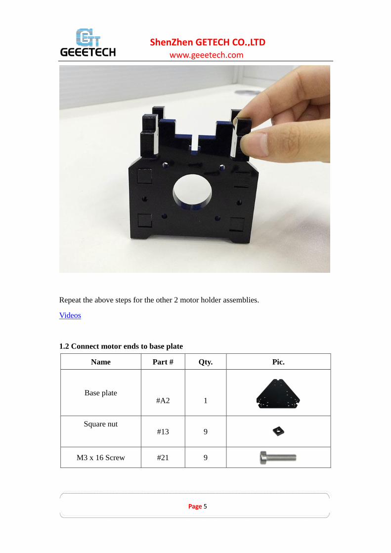
Repeat the above steps for the other 2 motor holder assemblies.
Videos
1.2 Connect motor ends to base plate
Name Part # Qty. Pic.
Base plate
#A2
1
Square nut
#13 9
M3 x 16 Screw #21 9

www.geeetech.com
Page 6
ShenZhen GETECH CO.,LTD
M3 washer
#5 21
Stepper motor
#57
3
Pulley
#36 3
M3 x 12 Screw
#20
12
Step1: Mount the motor holder assemblies to the 3 tower locations of the base
plate (#A2). Fix them with 9 M3 x 16 Screws (#21), Square nuts (#13)
and M3 washers (#5).

www.geeetech.com
Page 7
ShenZhen GETECH CO.,LTD
Step 2. Mount the pulley on to the motor shaft. One of the screws should be
screwed on the flat section of the shaft – ensure to screw them tightly, be
careful not to damage the screws.
Note: Pulley looks different here in the picture, but it will not affect the assembly and
use.
Step 3. Mount the 3 motors to the assembled motor holders. Fix them with the
M3x12 screws (#20) and M3 washers (#5).
* Note: It is better to have the wire connector mounted so then it is facing either left
or right. Do not mount it so the connector is facing up or down as it will
interfere with the base or the table.

www.geeetech.com
Page 8
ShenZhen GETECH CO.,LTD
Videos
1.3 Mount the LCD panel
Name Part # Qty. Picture
LCD frame
#A8
1
LCD support
#A9
2
LCD2004
#54
1

www.geeetech.com
Page 9
ShenZhen GETECH CO.,LTD
Square nut
#13
4
M3 x 16 Screw
#21
4
M3 x 12 Screw
#20
4
Spacer
#39
4
M3 washer
#5
8
Knob
#53
1
Upgrade item: LCD2004. We have upgraded the LCD controller connector so that it
can be compatible with more control board.
In this kit, we will use the FPC Ribbon cable. Pictures shown in the following steps
are another type. But this will not affect the assembly. Please feel free to go on with
the assembly.

www.geeetech.com
Page 10
ShenZhen GETECH CO.,LTD
Step 1. Attach the LCD frame (#A8) to the support plate (#A9) with the M3 x 16
Screws (#21) and M3 square nuts (#13).
Step 2. Plug the aircraft-type spacer (#39) in to the 4 screw holes on the LCD2004
(#A8) frame.
www.geeetech.com
Page 11
ShenZhen GETECH CO.,LTD
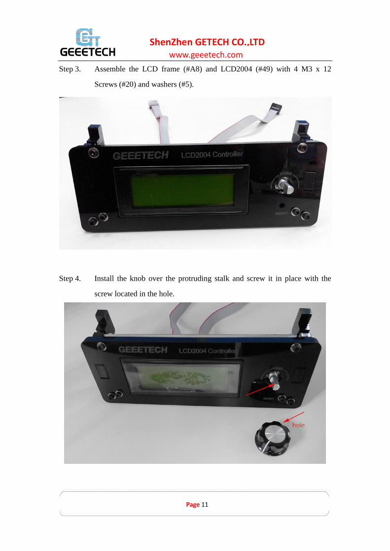
Step 3. Assemble the LCD frame (#A8) and LCD2004 (#49) with 4 M3 x 12
Screws (#20) and washers (#5).
Step 4. Install the knob over the protruding stalk and screw it in place with the
screw located in the hole.

www.geeetech.com
Page 12
ShenZhen GETECH CO.,LTD
Step 5. Mount the assembled LCD kit onto the base plate. Screw it up with 2 M3
x 16 screws (#21), M3 square nuts (#13) and washers (#5).

www.geeetech.com
Page 13
ShenZhen GETECH CO.,LTD
Videos
1.4 Mount the fan
Name
Part # Qty. Picture
Fan (40x40x10)
#48
1
M3 x 16 Screw
#21
1
M3 x 25 screw
#23
2

www.geeetech.com
Page 14
ShenZhen GETECH CO.,LTD
M3 Square nut
#13
1
M3 nut
#9
2
M3 washer
#5
3
Step 1. Mount the fan to the fan mount, screwing it up with 2 M3 x 25 screws
(#23), M3 nuts (#9) and washers (#5).

www.geeetech.com
Page 15
ShenZhen GETECH CO.,LTD
Step 2. Mount the assembled fan mount to the base plate (#A2) with a M3 x 16
screw (#21) and M3 square nut (#13) and washer (#5).
Videos
1.5 Mount the control board.
Name
Part # Qty. Picture
Control board
GTM32 set
#55
1

www.geeetech.com
Page 16
ShenZhen GETECH CO.,LTD
Spacer
#39 4
M3 x 12 Screw
#20
4
M3 washer
#5
4
Step 1. Plug the aircraft-type spacer (#39) into the 4 screw holes on the underside
of the control board (#55).
Step 2. Attach the control board (#55) to the base plate (#A2) with 4 M3 x 12
Screws (#20) and m3 washers (#5).

www.geeetech.com
Page 17
ShenZhen GETECH CO.,LTD
Don’t forget to stick the heat sink (#44) on the chip of the A4988 stepper motor driver
with sticker (#43).
Videos (in the video, we take GT2560 control board as example, still you can refer to
it)
1.6 Mount the print bed.
Name
Part # Qty. Picture
Building platform
#M5
1
Heat-bed
#56
1
Hex
sunk screw
#15
3
Spring
3.5 x 20mm
#30
3
Wing nut
#12
3
M3 washer
#5
6

www.geeetech.com
Page 18
ShenZhen GETECH CO.,LTD
* Note: For your convenience the heat-bed has been pre-soldered you can quickly
and easily mount them together.
Step1. Stack the building platform (#M5) on top of the heat-bed (#56) keeping the
holes aligned.
Do not let the soldered part directly attached to the metal building platform in case of
short circuit

www.geeetech.com
Page 19
ShenZhen GETECH CO.,LTD
Step 2. Thread the M3x30mm Hex sunk screw (#15) through the building
platform (M5) and heat-bed (#56), add washers (#5) and spring (#30); the
assembly should now like this:

www.geeetech.com
Page 20
ShenZhen GETECH CO.,LTD
Step 3. Locate the assembly over the holes provided in the base plate (#A2) anf
then lock the complete assembly in place with a wing nut (#12).
Here is the finished picture.
Make sure the building platform is leveled.

www.geeetech.com
Page 21
ShenZhen GETECH CO.,LTD
Videos
2 Top Plate Assembly
2.1 Drive wheel mount
Name
Part # Qty. Picture
Drive wheel mount
#A5
3
M3x25 Screw
#23
6
M3 nut
#9
6
M3 washer
#5
6

www.geeetech.com
Page 22
ShenZhen GETECH CO.,LTD
Step 1. Mount the drive wheel mount to the top plate (#A5) on A1; screw them up
with M3 x 25 screws (#23) , M3 nut (#9) and washers (#5).
Repeat the procedure for the other two drive wheel mounts.
Videos
2.2 Endstop mount
Name
Part # Qty. Picture
Top plate
#A1
1
Endstop mount
#A6
3
Endstop
#47
3
M2.5 x 16 screw #17 6

www.geeetech.com
Page 23
ShenZhen GETECH CO.,LTD
M3 x 16 Screw
#21
3
Square nut
#13
3
M3 washer
#5
9
M2.5 nut
#8
6
Upgraded item: The holes design of the extruder is upgraded to fit different model of
Rostock type 3d printers, such as the single extruder, the dual extruder and this 3
extruder model.
Step 1. Mount the three endstops (#47) onto the endstop mounts (#A6) in the same
direction. Fix in place with M2.5 x 16 screws (#17) and M2.5 nut (#8)
ensuring that they are tightly fixed.

www.geeetech.com
Page 24
ShenZhen GETECH CO.,LTD
Step 2. Bend the wire connector a small amount taking care not to break the
connector.

www.geeetech.com
Page 25
ShenZhen GETECH CO.,LTD
Note: You should be very gentle and note the direction, or the connector will
easily break.

www.geeetech.com
Page 26
ShenZhen GETECH CO.,LTD
Step 2. Mount the assembled parts onto the top plate (#A1). And attach them
with the M3 x 16 screws (#21), M3 square nuts (#13) and M3 washers (#5).
Again, take note of the endstop mounting direction.
* Note:
1. The opening of all the endstops should either be in the clockwise or anti-clockwise
direction – but they need to be all mounted in the same direction.
2. As we have upgraded the wire of the endstops, now the wire color for the endstop is
fixed now. You can identify the axis by the laser engraving mark on the top plate.
RED X axis
Blue Y axis
Black Z axis
(*Wire color in this picture is not right)

www.geeetech.com
Page 27
ShenZhen GETECH CO.,LTD
X axis endstop
Y axis endstop
Z axis endstop
www.geeetech.com
Page 28
ShenZhen GETECH CO.,LTD
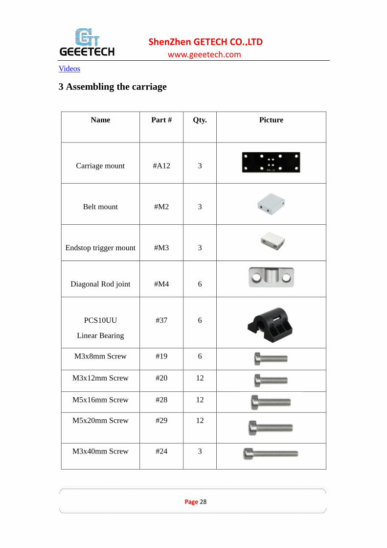
Videos
3 Assembling the carriage
Name
Part # Qty. Picture
Carriage mount
#A12
3
Belt mount
#M2
3
Endstop trigger mount
#M3
3
Diagonal Rod joint
#M4
6
PCS10UU
Linear Bearing
#37
6
M3x8mm Screw #19 6
M3x12mm Screw #20 12
M5x16mm Screw #28 12
M5x20mm Screw #29 12
M3x40mm Screw #24 3

www.geeetech.com
Page 29
ShenZhen GETECH CO.,LTD
Spring
#31
3
M3 washer
#5
24
Rod-end bearing
holder
#3 6
M5 nut #10 24
* PCS8UU linear bearings is a modified version of PCS8UU linear bearings, the
block is made of high strength ABS, which is lighter and more flexible.
Why we changed the PCS8UU linear bearings into the PCS8UU ?
To lighten the loads of the carriage in case it slide down during printing and to reduce
the drag of each axis so that the carriage can move more flexible therefore increase
the precision of printing.

www.geeetech.com
Page 30
ShenZhen GETECH CO.,LTD
Step 1. Fix the belt mount (#M2)on the carriage mount (#A12) using 2 M3 x12
screws (#20) and washer (#5).
Step 2. On the other side of the carriage mount (#A12) fix the endstop trigger
mount again with 2 M3 x 12mm screws (#20) and washer (#5).
Step 3. Connect the diagonal rod joint (#M4) and the PCS10UU linear bearing
(#37) on to the carriage mount (#A12) ensuring that the bearing sleeves
(round holes to fix the rod-end bearing holder) are mounted to the outside
of the assembly (refer to the picture below). Fix with M5x16mm screws
(#28) and M5x20mm screws and M5 nuts.
Note: Take special note of the direction of the diagonal rod joint, the wider edge
is near the Endstop trigger mount.

www.geeetech.com
Page 31
ShenZhen GETECH CO.,LTD
Step 3. Now insert the M3x40mm screw (#24) into the endstop trigger mount with
a spring (#31) in between. Here you need to use washers (#5) to
correctly complete the assembly.
www.geeetech.com
Page 32
ShenZhen GETECH CO.,LTD
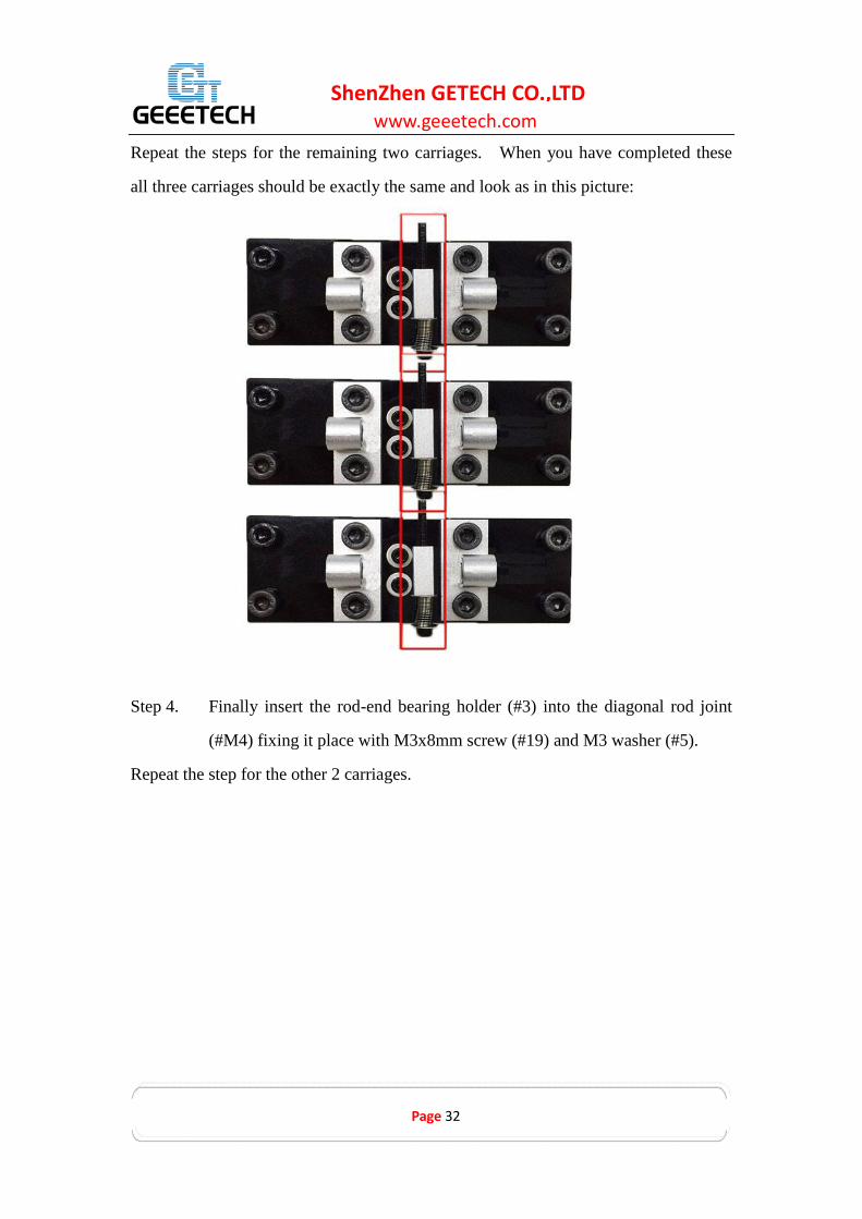
Repeat the steps for the remaining two carriages. When you have completed these
all three carriages should be exactly the same and look as in this picture:
Step 4. Finally insert the rod-end bearing holder (#3) into the diagonal rod joint
(#M4) fixing it place with M3x8mm screw (#19) and M3 washer (#5).
Repeat the step for the other 2 carriages.

www.geeetech.com
Page 33
ShenZhen GETECH CO.,LTD
Videos
4. Mount the print head.
Video
4.1 Mount the hotend.
Name
Part # Qty. Picture
Hotend
#60
1
M3 x 16 screw
#21
3
Spider
M1
1

www.geeetech.com
Page 34
ShenZhen GETECH CO.,LTD
Step 1.Mount the hotend (#60) on the spider (#M1) with 3 M3 x 16 screws (#21).
4.2 Mount the rod-end bearing holder and diagonal rod
Name
Part # Qty. Picture
Diagonal Rod
#4
6

www.geeetech.com
Page 35
ShenZhen GETECH CO.,LTD
rod-end bearing
holder
#3
6
Round head screw
with pad
#16
6
M3 washer #5 6
M3 x 8 screw
#19
6

www.geeetech.com
Page 36
ShenZhen GETECH CO.,LTD
Step 1. Insert the rod-end bearing holder (#3) into the diagonal rod joint location
of the spider (#M1), fix it in place with M3x8mm screw (#19) and M3
washer (#5).

www.geeetech.com
Page 37
ShenZhen GETECH CO.,LTD
Step 2. Slide the diagonal rod (#4) on to the rod-end bearing holder (#3) and fix it
in place with a round head screw with pad (#16).
5 Mount the smooth rods
Name
Part # Qty. Picture
Smooth Rod
#1
6

www.geeetech.com
Page 38
ShenZhen GETECH CO.,LTD
M4 x 8 Screw
#25
6
M8 Washers
#7
6
M4 washer
#6 6
Step 1. Slide a M8 washer (#7) on to an end of the smooth rod (#1). Insert that
end of the rod (#1) into one of the holes located on the tower of base plate
(#A1).
Step 2. Fix the rod (#1) in place with M4 washer (#6) and M4x8 screw (#25).

www.geeetech.com
Page 39
ShenZhen GETECH CO.,LTD
Step 2. Repeat this step for the remaining 5 rods (#1).
Videos

www.geeetech.com
Page 40
ShenZhen GETECH CO.,LTD
6 Mount the carriage and the top plate
Name Part # Qty. Picture
M4 x 8 Screw
#25
6
M8 Washers
#7
6
M4 washer
#6
6
Step 1. Slide the carriages down the smooth rods (#1) pairing one carriage with
each set of 2 smooth rods (#1). You should now have the beginnings of
three towers (X, Y and Z).

www.geeetech.com
Page 41
ShenZhen GETECH CO.,LTD
*Note: At this point it may be a good opportunity to check that the carriage
endstop screws (#24) actually connect with the endstops (#47). Align the
top place (#A1) on to the top of the rods (#1) and check that the endstops
are correctly orientated.
*Note: If you find it difficult to slide the carriage along the rod, or the carriage
does not slide smoothly, you can slightly loosen the screws on the difficult
linear bearing (#37) to release some alignment pressure with the smooth
rod (#1).
Step 2. Slide a M8 washer (#7) on each top of each smooth rod (#1) and then align
the top plate (#A1) and smooth rods (#1) until with some pressure the top
place (A1) slides on to the three towers. Fix the top place (A1) in place
with the M4x 8 screws (#25) and M4 washers (#6).

www.geeetech.com
Page 42
ShenZhen GETECH CO.,LTD
*Photos with PCS8UU linear bearings in this instruction is the previous version, here
we use PCS8UU instead. Picture is just for reference.

www.geeetech.com
Page 43
ShenZhen GETECH CO.,LTD
Videos

www.geeetech.com
Page 44
ShenZhen GETECH CO.,LTD
7 Mount the Belt
7.1 Assemble the drive wheel
Part name Part # Qty. Picture
Drive wheel holder #35 3
Drive wheel #34 3
R84zz Ball Bearing #33 6
M3 x16mm screw #21 3
M4 x 20mm screw #27 3
M4 washer #6 3
M4 lock nut #11 3
wing nut #12 3

www.geeetech.com
Page 45
ShenZhen GETECH CO.,LTD
Step 1. Thread the M3 x 16 screw (#21) through the top hole on the drive wheel
holder (#35).
Step 2. Pick up 2 MR84zz ball bearings (#33). Insert 1 MR84zz ball bearings
(#33) into both ends of the drive wheel (#34). (We have done this step
for you before shipping)

www.geeetech.com
Page 46
ShenZhen GETECH CO.,LTD
www.geeetech.com
Page 47
ShenZhen GETECH CO.,LTD
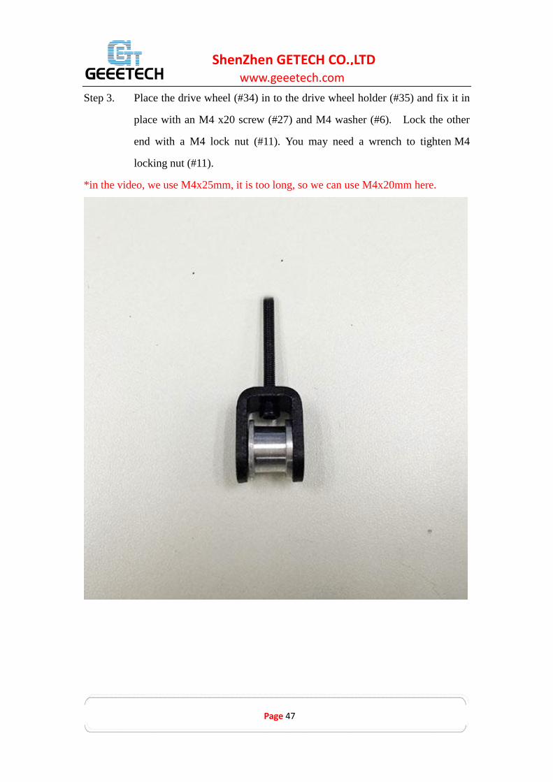
Step 3. Place the drive wheel (#34) in to the drive wheel holder (#35) and fix it in
place with an M4 x20 screw (#27) and M4 washer (#6). Lock the other
end with a M4 lock nut (#11). You may need a wrench to tighten M4
locking nut (#11).
*in the video, we use M4x25mm, it is too long, so we can use M4x20mm here.
www.geeetech.com
Page 48
ShenZhen GETECH CO.,LTD
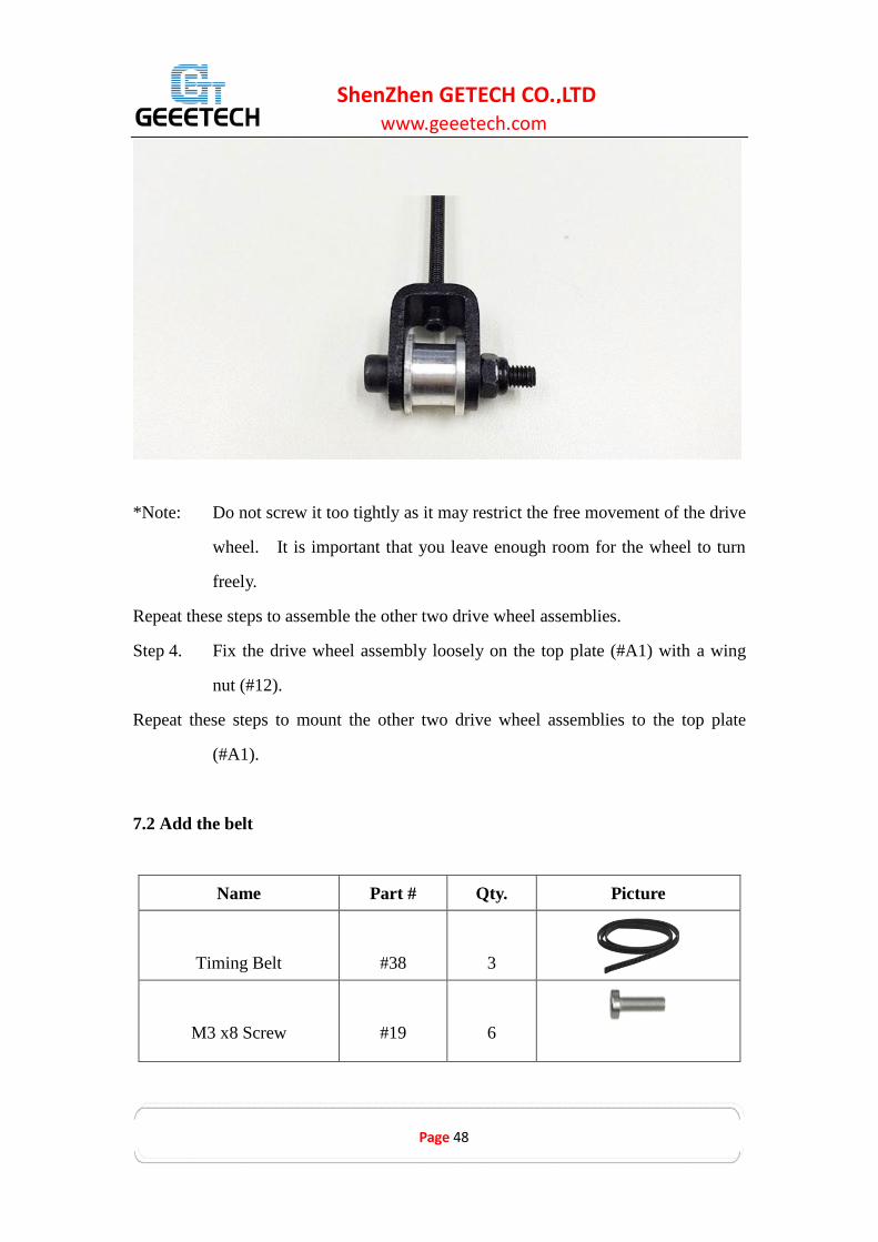
*Note: Do not screw it too tightly as it may restrict the free movement of the drive
wheel. It is important that you leave enough room for the wheel to turn
freely.
Repeat these steps to assemble the other two drive wheel assemblies.
Step 4. Fix the drive wheel assembly loosely on the top plate (#A1) with a wing
nut (#12).
Repeat these steps to mount the other two drive wheel assemblies to the top plate
(#A1).
7.2 Add the belt
Name Part # Qty. Picture
Timing Belt
#38
3
M3 x8 Screw
#19
6

www.geeetech.com
Page 49
ShenZhen GETECH CO.,LTD
M3 washer #5 6
Step 1. Thread the timing belt (#38) through the drive wheel with the pitched side
in direct contact with the drive wheel and the smooth side facing out.
Step 2. Punch a 2-2.5mm hole in to the timing belt with a leather hole punch or
similar (not supplied).
Step 3. Fix one end of the timing belt to the belt mount (#M5) with an M3x8mm
screw (#18) and M3 washer (#5).
Step 4. Guide the timing belt around the motor pulley (#36) and back up to the
underside of the belt mount (#M2). Mark the location of the new hole to be punched
to allow the timing belt to be fixed to the belt mount. Trim the timing belt, punch
the hole and fix it to the belt mount with a M3x8mm screw (#19) and M3 washer (#5).
www.geeetech.com
Page 50
ShenZhen GETECH CO.,LTD
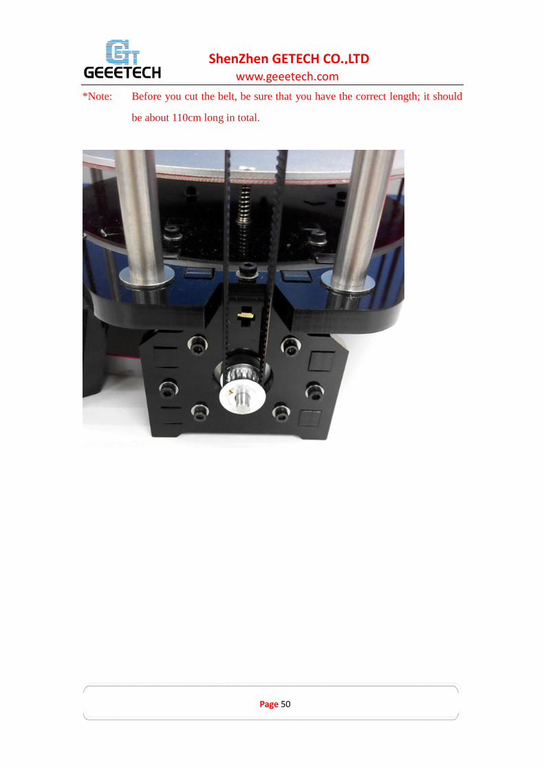
*Note: Before you cut the belt, be sure that you have the correct length; it should
be about 110cm long in total.

www.geeetech.com
Page 51
ShenZhen GETECH CO.,LTD
Step 5.Tighten the wing nut (#12) to to reduce the slack in the timing belt.
Repeat the above steps for the other 2 timing belts.
Videos
8 Connect the Diagonal Rod to the carriage
Video
Name Part # Qty. Picture
Round head screw with pad
#16
6

www.geeetech.com
Page 52
ShenZhen GETECH CO.,LTD
Step 1. Place the print head assembly on to the building platform.
Step 2. Working with the “X” axis first, slide the diagonal rod (#4) on to the on the
rod-end bearing holder located on the assembled print assembly, fixing it
on with a round head screw with pad (#16).
Step 3. Fix the other end of the diagonal rod (#4) to the carriage located on the “X
axis” tower with a round head screw with pad (#16).

www.geeetech.com
Page 53
ShenZhen GETECH CO.,LTD
*You can insert the PTFE pipe later after extruder is mounted.
Fix the remaining diagonal rods (#4) to the carriages with a round head screw with
pad (#16).
Videos
9 Mount the extruder
Video
Name Part # Qty. Picture

www.geeetech.com
Page 54
ShenZhen GETECH CO.,LTD
Extruder
#58
3
Extension board
#59
3
Extruder wire
#52
3
Extension wire
#49
1
Extruder Motor wire
#51
3
Hex copper spacer
#46
6
Extension board cover
#M6
3
M3 x 5screw #15 12

www.geeetech.com
Page 55
ShenZhen GETECH CO.,LTD
M4 x 12 screw
#26
8
Mount extruder 0(E0)
For this extruder, we will connect the wires of the hotend to it.
Step1. Take one extruder and mount it on the top plate with 4 M4x12mm screw.
Step2. Thread the motor wire and the fan wire on the extruder into the metal sheet. Do
the same with the wires on the hotend. You need to use the extension wire here for the
hotend fan.
Step3. Mount the extrusion extension board on the extruder with 2 M3x5mm screws
and hexagon copper spacer.
Note: the black connector should be faced to the fan of the extruder.
Step4. Connect the wires as shown in the following picture.
Step5. Cover the extension board, fix the cover on the hexagon copper spacer with 2
M3x5mm screw.

www.geeetech.com
Page 56
ShenZhen GETECH CO.,LTD
Mount extruder 1(E1) and extruder 2(E2)
Extruder 1 and Extruder 2 are much easier to be assembled. You can follow the above
steps except that there are no wires for the hotend, so you just need to connect the
motor wire and the fan wire.
You can finish the extruder assembly first and then mount them on the top plate.

www.geeetech.com
Page 57
ShenZhen GETECH CO.,LTD

www.geeetech.com
Page 58
ShenZhen GETECH CO.,LTD

www.geeetech.com
Page 59
ShenZhen GETECH CO.,LTD
Cut a piece of PTFE pipe and insert it into the filament feeding hole.
10 Mount the filament holder
Note: If you prefer, this step can be left for the very end of the assembly and
configuration process.
Name
Part # Qty. Picture
Spool holder
Side panel
#A10
1

www.geeetech.com
Page 60
ShenZhen GETECH CO.,LTD
Spool holder
Side panel
#A11
1
M3x16 screw
#21
4
Square nut
#13
4
locking ring
#30
4
Filament Spool #2 1
Step 1. Fit the spool holder side panel (#A10) in to the locating holes on the top
plate (#A1) and fix in place with M3x16 screw (#21), M3 square nut (#13)
and washer (#5).
Step 2. Repeat the previous step with the other spool holder side panel (#A10)
fixing in place with M3x16 screw (#21), M3 square nut (#13) and washer
(#5).
Step 3. Slide the Filament Spool (#2) through the holes and lock the two sides in
place with the locking rings (#30). Then put filament on the two sides and
lock them with locking rings.
You can finish this step later when you start printing.
Video

www.geeetech.com
Page 61
ShenZhen GETECH CO.,LTD

www.geeetech.com
Page 62
ShenZhen GETECH CO.,LTD
11 Connect the Bowden tubes
Name
Part # Qty. Picture
bowden tubes
#41
3
Step 1. Plug one end of the bowden tubes (#1) into the push-fitting located at the
top of the hot end (identified by the blue plastic ring) and the other end
into that of the extruder.
Note: Before connecting the feeding pipe, you need to match the extruder and
the hot end. From the viewpoint of back (“Z” tower) the left side
extruder is referred to as “extruder 0” and the right one is “extruder 2”.

www.geeetech.com
Page 63
ShenZhen GETECH CO.,LTD
1. Before inserting the bowden tube into the HeatSinks, cut off a small piece
perpendicular the end as to make a perfect right angle cut. This is to eliminate the
gap between the tube and the hotend which will also help avoid clogging.
2. At the motor end of the bowden tube, drill the inside of the tube using an exacto
knife (or another sharp tool) in order to create a small funnel. When loading
filament this will help guide the filament into the tube. Be absolutely sure to
remove all excess from drill remaining before inserting the tube into the extruder
coupling since you do not want this residue ending up inside the hotend as it will
most likely cause clogging of your hotend.
3. Prior to applying filament you must fully insert the bowden tubes (approx. 60 mm)
into the end of the three HeatSinks. If you do not, the HeatSinks will get clogged
and the filament gets stuck!
www.geeetech.com
Page 64
ShenZhen GETECH CO.,LTD
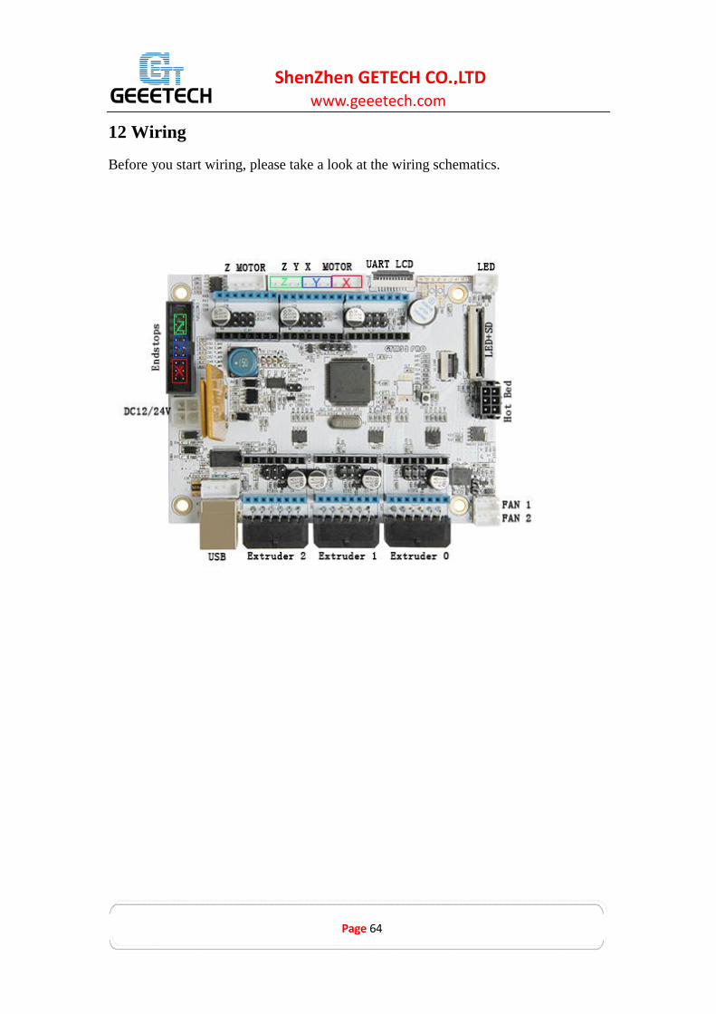
12 Wiring
Before you start wiring, please take a look at the wiring schematics.

www.geeetech.com
Page 65
ShenZhen GETECH CO.,LTD
1 Connect wires for motors.
Step 1.Connect wires for E0.
Step 2.Connect wires for E1.

www.geeetech.com
Page 66
ShenZhen GETECH CO.,LTD
Step 3.Connect wires for E2.
2 Connect X/Y/Z motor(s)
Step 1.Identify which MOTOR you are connecting; this connector plug is for X/Y/Z.

www.geeetech.com
Page 67
ShenZhen GETECH CO.,LTD
3Connect heat-bed wires
4 Connect wires for endstop

www.geeetech.com
Page 68
ShenZhen GETECH CO.,LTD
6 Connect wires for Fan
Step 1.Connect control board fan to FAN0.

www.geeetech.com
Page 69
ShenZhen GETECH CO.,LTD
7. Connect wires for LCD panel
8 Connect wires for power input

www.geeetech.com
Page 70
ShenZhen GETECH CO.,LTD
13 Assembly of PSU protective case
Name
Part NO. Qty Pic
Power Supply
Unit
NO.58
1
Power Cable
#63
1
Power Cable
#60
1
PSU case part1
A13
1

www.geeetech.com
Page 71
ShenZhen GETECH CO.,LTD
PSU case part2
A14
2
PSU case part3
A15
1
PSU case part4
A16
1
Hex
sunk screw
#14
2
M3 nut #9 2
M3 x 12 mm screw
#20 6
Square nut
#13
6
M3 x 5mm screw
#18 3
Video

www.geeetech.com
Page 72
ShenZhen GETECH CO.,LTD
Caution: You must take extreme care at this point. Ensure that you connect
the correct wires to the corresponding locations on the power supply.
Step 1. Connect the wires as shown below.
You should take note of the colors and their corresponding connection as a mistake
can cause you harm or damage the printer. If you are unsure of your skills and
abilities here, please consult a professional.

www.geeetech.com
Page 73
ShenZhen GETECH CO.,LTD
BROWN Live (L)
BLUE Neutral (N)
GREEN / Ground (GND)
YELLOW
RED Positive (+)
BLACK Common (COM)
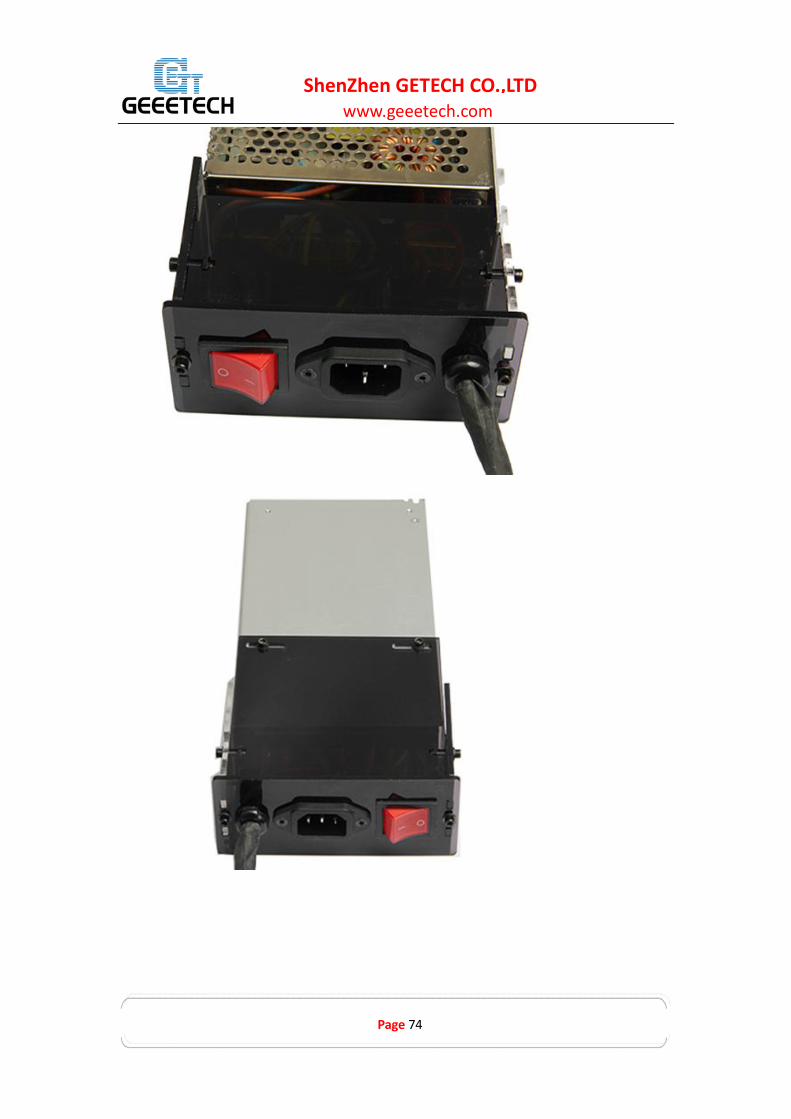
As the power supply unit (PSU) is not physically connected to the actual printer, it is
best to be kept next to the printer, you should take good care of it; keep it away from
kids and pets.
We add a protective case for the PSU.
www.geeetech.com
Page 74
ShenZhen GETECH CO.,LTD

www.geeetech.com
Page 75
ShenZhen GETECH CO.,LTD
14Tidy out the wires
Use the provided spiral coil and zip ties to neatly bundle those wires together.
If you bundle the wires up before wiring the printer, you are advised to mark each
wire with its function or location so as not to mix them up.

www.geeetech.com
Page 76
ShenZhen GETECH CO.,LTD

www.geeetech.com
Page 77
ShenZhen GETECH CO.,LTD

www.geeetech.com
Page 78
ShenZhen GETECH CO.,LTD

www.geeetech.com
Page 79
ShenZhen GETECH CO.,LTD
The Rostock 301 has been fully assembled.

www.geeetech.com
Page 80
ShenZhen GETECH CO.,LTD
15 Tips
Before printing your first project, it is critical that you correctly calibrate the printer.
Skipping or rushing this step will result in frustration and failed prints later, so it is
important to take the time to make sure your printer is correctly set up.
Each printer will have its own calibration procedure and this manual can not attempt
to cover every variations and possible scenario. Instead we have provided you with
a list of key points that should be addressed as your configuration and set up
procedure.
Frame is stable and correctly aligned.
Rods are correctly aligned
Belts are taut.
Driving wheel turns smoothly
Bed is level in relation to the path of the extruder.
Filament rolls freely from the spool, without causing too much tension on the
extruder.
Current for stepper motors is set to the correct level.
Wires are correctly connected
Couplings and pulleys are fixed tightly
Firmware settings are correct including: axis movement speeds and acceleration;
temperature control; end-stops; motor directions.
Extruder is calibrated in the firmware with the correct steps per mm of filament.
The point regarding the extruder step rate is vital. Slic3r expects that the machine will
accurately produce a set amount of filament when told to do so. Too much will result
in blobs and other imperfections in the print, too little will result in gaps and poor
inter-layer adhesion.