geh-15290 supersedes geh-1529c demand …€¦ · · 2014-03-24geh-15290 supersedes geh-1529c...
TRANSCRIPT
INSTRUCTIONS GEH-15290 Supersedes GEH-1529C
TYPE M-30
DEMAND REGISTERS
GENERAL . ELECTRIC www . El
ectric
alPar
tMan
uals
. com
www . El
ectric
alPar
tMan
uals
. com
2
TABLE OF CONTENTS
INTRODUCTION GENERAL DESCRIPTION OPERATING PRINCIPLE SCALES
Page
..... 3
SCALE RATING OF REGISTERS UNIVERSAL REGISTERS INSTALLATION RESETTING OF DEMAND POINTER CARE AND MAINTENANCE
Cleaning Register Type SG-1 Motor With Type Disassembly of Register Reassembly of Register
ADJUSTMENTS
B-14 Rotor
TESTING WAlTHOUR DEMAND METERS TESTING DEMAND REGISTERS ......... . DIMENSIONS ....... . SELF-CHECKING ADAPTER" FRICTION CHECKING DEVICE
Calibration of Checking Device Use as Laboratory Device Use as Portable Device
GENERAL TYPE IM-50 (SPECIAL INSTRUCTIONS INCLUDING DIAGRAMS) CONNECTION DIAGRAMS ............. .
Type IM-16, Fig. 12 Type IM-18, Fig. 13 Type IM-20, Fig. 14 and 15 Type IM-30, Fig. 16 ........ .
20 and
Type VM-2, Fig. 17 .............................. . Types VM-3, -5, and -6, Fig. 18 and 19 ....... 23 and Types VM-4, -7, -9, and -10, Fig. 21 ........................ .
3 3 5 5 5
.6 7 7 7 8 8
10 12 13 13 13 13 15 15 15 17 17 18 19 19 20 21 22 22 24 25
Types DM-6, -7, Fig. 22 ....... . . . 26 Types DM-14, 3-wire, 2- or 3-phase and 4-wire, 2-phase, Fig. 23 27 Type DM-14, 4-wire D. , 3-phase, Fig. 24 .................................. 27 Types ISM-8, -9, DSM-19, -20, -34, and -35, Fig. 25 Type DM-15, 4-wire Y, 3-phase, Fig. 26 Type DM-15, 4-wire 6 , 3-phase, Fig. 27 . Type DM-15 Totalizing, Fig. 28 .. Types DSM-38, -40, and -43, Fig. 29 Types DSM-39, -41, and -44, Fig. 30 ...... . Types ISM-10, -11, and -12, Fig. 31 Dimensions of Watthour Demand Meters, Fig. 32
27 28 28
. ................. 29 ... 29
. .................. 29 . . . . . . . . .... 29
30
These instructions d o not purport t o cover all details o r variations i n equipment nor t o provide for every possible contingency to be met in connection with installation, operation or maintenance. Sho>ld further information be desired or should particular problems arise which are not covered sufficiently for the purchaser's purposes, the matter should be referred to the General Electric Company.
0
0
www . El
ectric
alPar
tMan
uals
. com
www . El
ectric
alPar
tMan
uals
. com
TYPE M-30 DEMAND REGISTERS for use with
WAlTHOUR DEMAND METERS
TYPES DM-6, -7, -14, -15; TYPES DSM-19, -20, 34, -35, -38, -39, -40,
-41, -43, -44; TYPES IM-16, -18, -20, -30, - SO; TYPES ISM-8, -9,-10,-11,
-12; AND TYPES VM-2, -3, -4, S, -6, -7, -9, -10.
INTRODUCTION
When the register of a standard General Electric
watthour meter is replaced by a demand register, the
resulting combination is a "watthour demand meter". These instructions cover the operation, maintenance,
adjustment, and testing of the Type M-30 demand
register as well as its installation on watthour meters
of the following (and related) types: Types D-6, -7,
..- 14, - 15; Types DS- 19, -20, -34, -35, -38, -39, -40, -41,
-43, -44; Types I- 16, - 18, -20, -30, -SO; Types IS-8, -9,
- 10, - 1 1, - 12; and Types V-2, -3, -4, -5, -6, -7, -9, - 10. The "watthour demand meters" are identical to
corresponding types of watthour meters except for the
register, connection leads and cover, and the addition of the type letter "M" following the regular type letter. For example, the VM-3-A is exactly like the V -3-A except that a demand register is used in place of the ordinary register, and the cover is deeper than
the standard watthour-meter cover and has a manual
resetting device. The register indicates kilowatthour consumption by
means of dials and pointers, and maximum kilowatt
demand, averaged over a definite time interval, by a
long pointer over a graduated scale.
GENERAL DESCRIPTION
The M-30 demand register is of the block interval type in which a pointer pusher is geared directly to the watthour-meter shaft through a suitable gear reduction and arranged to carry the indicating pointer with it as it moves up scale. In this gear train is a clutch which will open and slip to permit the pointer pusher to be brought back to its zero position. The pointer, since it is not rigidly attached to the pointer pusher, remains at the highest point on the scale to which it has been pushed and is held there by friction.
During the time interval, the pointer pusher is driv
en up scale at a rate proportional to the load on the
watthour meter. It carries with it the pointer mechan
ism, if the pointer has not previously been advanced
through the range covered by the pointer pusher
during the interval under consideration. At the end
of each time interval the pointer pusher is returned
to its zero position by the resetting mechanism.
A synchronous motor is used to drive the timing
and resetting mechanism. The complete motor as
sembly can be lifted from the register by slightly loosening the two mounting screws, one on either side of the coils. The motor drives the timing train through
an over-running clutch making it possible to advance
the train manually without disturbing any adjustment.
The progress of the time interval may be noted on the small black disk on the front of the register. The
disk moves intermittently at such a rate that one com
plete revolution is equal to the duration of the time interval, thereby giving at a glance the elapsed time in that particular interval.
OPERATING PRINCIPLE
The following is a description of the operating principle of the Type M-30 demand register. Refer
ences are to Fig. 1 ( 30-minute time interval register shown).
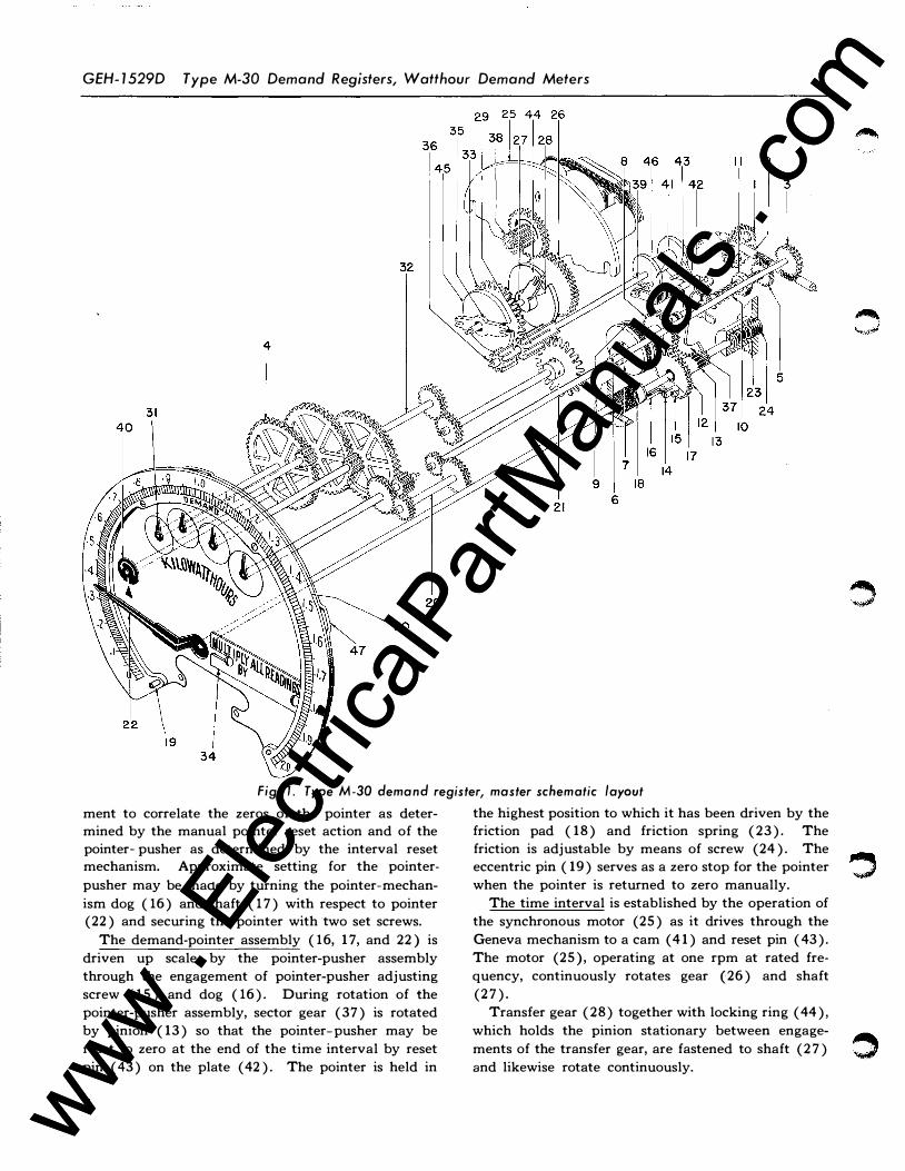
The worm wheel ( 1 ), meshes with a worm on the watthour-meter shaft and through worm shaft (2)
drives the kilowatthour and demand gear trains. The kilowatthour dials are driven by a simple gear train consisting of worm wheel (3), ratio shaft (20), and pointer gear shafts ( 4) behind the dial plate.
The demand gear train consists of the clutch-shaft assembly, the pointer-pusher assembly, and the demand-pointer assembly.
The clutch-shaft assembly is driven by worm wheel
( 5) which is fastened to shaft ( 6). Clutch disk ( 7) is also secured to this shaft. Gear ( 8) is free to turn on shaft ( 6) and is driven by it through friction pad (9). Spring ( 10) and adjusting nut ( 1 1) provides means of adjusting the pressure on the friction pad
and thereby its friction torque. Gear (8) meshes
with gear ( 12) on pointer-pusher pinion sleeve ( 13)
which is free to turn on shaft ( 17).
The pointer-pusher assembly carries on its gear
( 12) a post ( 14) which engages with formed dog ( 16)
on pointer-mechanism shaft ( 17). The contact be
tween ( 14) and ( 16) is through pointer-pusher
adjusting screw ( 15) which provides a fine adjust-
3 www . El
ectric
alPar
tMan
uals
. com
www . El
ectric
alPar
tMan
uals
. com
GEH- 1 529D Type M-30 Demand Registers, Watthour Demand Meters
Fi g. 1. Type M-30 demand regi ster, master schemati c layout
ment to correlate the zeros of the pointer as determined by the manual pointer reset action and of the pointer- pusher as determined by the interval reset mechanism. Approximate setting for the pointer
pusher may be made by turning the pointer-mechan
ism dog ( 16) and shaft ( 17) with respect to pointer (22) and securing the pointer with two set screws.
The demand-pointer assembly ( 16, 17, and 22) is
driven up scale by the pointer-pusher assembly
through the engagement of pointer-pusher adjusting
screw ( 15) and dog ( 16). During rotation of the
pointer-pusher assembly, sector gear (37) is rotated
by pinion ( 13) so that the pointer-pusher may be
reset to zero at the end of the time interval by reset
pin ( 43) on the plate ( 42). The pointer is held in
4
the highest position to which it has been driven by the friction pad ( 18) and friction spring ( 2 3). The friction is adjustable by means of screw (24 ). The eccentric pin ( 19) serves as a zero stop for the pointer � when the pointer is returned to zero manually.
The time interval is established by the operation of
the synchronous motor (25) as it drives through the
Geneva mechanism to a cam ( 4 1) and reset pin ( 43).
The motor (25), operating at one rpm at rated fre
quency, continuously rotates gear (26) and shaft
(27).
Transfer gear ( 2 8) together with locking ring ( 44),
which holds the pinion stationary between engage-
� . . . ments of the transfer gear, are fastened to shaft (27) .J and likewise rotate continuously.
www . El
ectric
alPar
tMan
uals
. com
www . El
ectric
alPar
tMan
uals
. com

Type M-30 Demand Registers, Watthour Demand Meters GEH- 1 529D
Transfer pm10n (29) is rotated intermittently on shaft ( 39) and intermittently drives gear ( 33) which, together with transfer gear ( 35) and locking ring ( 45) rotate freely on shaft (27). Transfer pinion (36) is thereby rotated intermittently one revolution each interval. Transfer pinion ( 36) is fastened to cam shaft (39) which, therefore, rotates reset cam and
pin assembly one revolution each interval in four intermittent 90 degree steps. Each 90 degree movement of the cam assembly takes nine seconds.
The interval resetting is accomplished first by the action of cam ( 4 1) in lifting clutch-lever assembly ( 46), thereby disengaging the clutch, and second by the intercepting of pin ( 43) with the tail of sector gear ( 3 7) which rotates pointer pusher ( 15) through
pinion sleeve ( 13) backward to its zero position away from the pointer-mechanism dog ( 16 ). The cam ( 4 1 ) has now closed clutch (9), thereby again allowing registration through shaft ( 6).
The duration of the time interval is determined by the number of sections or ends on the transfer gears
( 28) and ( 35). The combination of a single-ended
transfer gear ( 2 8) and double-ended transfer gear
( 35), is for a 30-minute-interval register as shown
in the figure. In a 15-minute register, both transfer gears are double ended.
The interval-indicator dial ( 40) is driven in intermittent steps through gear train ( 32), thereby indicating how much of the present interval has elapsed.
The overrunning clutch (38) on the motor (25) shaft drives gear (26). This permits the time train to be advanced or the pointer-pusher resetting opera
tion to be performed manually by turning the gears with the finger. The pinion on the overrunning clutch ( 38) is for engagement with the self-checking adapter
only, and is not part of the register-gear trains.
SCALES
All watthour demand meters are one of three classes, known as Class 1, 2, and 4. The following table sets forth the approximate overload values of the Type M-30 Class 2 demand registers when used on different types of watthour meters. When Class
1 registers are used, divide the values in the table
below by two to obtain the approximate full-scale
rating. When Class 4 registers are used, multiply the
values in the table below by 1.5 to obtain the approxi
mate full-scale rating (Class 4 registers are intended
primarily for use only on Type IM-30, 15-ampere
meters).
SCALE RATINGS OF REGISTERS
Type of Merer
Approximate Fullscale Raring in Per
Cent of Meter Rating •
Self- Used with contained C T
IM- 16, -20, -50
IM-30 (except 15A)
ISM-8, -9, -10, - 1 1, - 12, same as IM- 16
IM-18
DM-6, -7, 2-phase, 3- or 4-wire DM-6, -7, 3-phase, 3-wire DM-6, -7, 3-phase, 4-wire Y DM- 14, 2-phase, 3- or 4-wire
DM- 14, 3-phase, 3-wire DM- 14, 3-phase, 4-wire Y DM- 14, 3-phase, 4-wire b. DM-15, 3-phase, 4-wire Y DM- 15, 3-phase, 4-wire 6. DM- 15, Totalizing 3-phase, 3-wire
330
330
330 165
190 180 330
380 330 240 330 370
165
165
165
190 180 165 190 165 120 165
185
and 2- or 3-wire single phase 370 185 DSM- 19, -34, -38, -40, -43, same as
DM-14
DSM-20, -35, -39, -41, -44, same as DM- 15
VM-2, 3-element, 3-wire 330 VM-2, 3-phase, 3-wire 380 VM-3, 2-phase, 3- or 4-wire 330 VM-3, 3-phase, 3-wire 380 VM-4, -5, 3-phase, 4-wire 330 VM-6, 3-phase, 4-wire L 240 VM-7, 3-phase, 4-wire 6. 370 VM-9, - 10, same as DM-15 Totaliz-
ing
IM-30, 15A, with class 4 register 4 15
165 190 165
120 185
"'The meter rating is based on 120 volts or multiples thereof and is
determined as follows: single-phase: Ex!; 2-phase: 2xExl; '\-wire. 3-phase: yf3xExl; 4-wire Y. 3-phase: 3xExl; 4-wire 6 . 3-phase and totalizing
meters: ( y3 + 1) xExl. For 2.5-amp meters used with C T the meter
rating is based on the secondary rating of the C T, i.e., I = 5 amp.
UNIVERSAL REGISTERS
The "Universal Register" is a standard Type M-30 demand register of a definite register ratio. This reg
ister ratio has been chosen as 166-2/3. It permits the use of register-dial multipliers which in practically
all cases will be whole numbers and which are de
termined as follows:
D. 1 M 1 . 1. Meter Constant* 1a u tlp 1er = -
0.6
( * This is shown on the meter nameplate as "K h''
or "Test K". In the case of Transformer Rated meters
5 www . El
ectric
alPar
tMan
uals
. com
www . El
ectric
alPar
tMan
uals
. com

GEH-1529D Type M-30 Demand Registers, Watthour Demand Meters
"Pri KJ{' or "Pri Test K" is used which equals "Khx
CT ratio xPT ratio".) An example of this calculation is shown below for
an M-30 Universal Register, ratio 166-2/3, on a type VM-4-A meter, 4-wire, 3-phase having a 100 amp cur
rent transformer, 20: 1 ratio, and a 4800 volt potential transformer, 40: 1 ratio, with the appropriate meter test constant of 0.9:
Meter Constant_
KhxCT ratio x PT Dial Multiplier= -
0.6 -
0.6
0.9 X 20 X 40
0.6 1200
Note: This is not the simple product of the CT ra
tio and PT ratio as on the secondary reading registers. A multiplier plate with the words "MULTIPLY
ALL READINGS BY" is included with each "Uni
versal Register". The dial multiplier, calculated as above, may be inserted on this plate and, since the plate is easily detachable, the multiplier may be changed any time.
Type M-30 registers are available with three differ
ent overload capacities identified by the class numbers 1, 2-, and 4. The full-scale value of a Universal
Register (ratio 166-2/3) Class 2 is 2 KW; of Class 1 is 1 KW; of Class 4 is 3 KW. (See chart on page 16.)
The "Universal Register" may be used with any rating of any watthour demand meter listed in these instructions, it being necessary only to apply the proper dial multiplier for the particular installation.
INSTALLATION
The registers are adjusted and checked for accuracy of registration at the factory and are ready for immediate installation.
They can be used only on General Electric meters of the types listed in these instructions. The demand register may be installed on watthour meters by mounting it in place of the kilowatthour register furnished on the watthour meters. For all front connected watthour meters, Types D-6, -7, - 14, - 15; Types I- 16,
-18, -20, -30, -SO; Type IS-9; and Types V-2, -3, -4, -5,
-6, -7, -9, - 10, a complete new glass cover with resetting
d.evice is furnished. For the switchboard meters,
Types DS-19, -20, -34, -35; and Type IS-8, new metal
covers complete with glass windows and resetting de
vices are supplied. For drawout meters, Types DS-38,
-39, -40, -41, -43, -44 and Types IS- 10, -11, - 12, only
a new cover with a reset device is required.
To install an M-30 register on a watthour meter the following steps are necessary :
1. Remove the kilowatthour register from the meter.
6
2. Remove the two mounting studs from the pack
ing bracket on which the Type M-30 register was received.
Note: If register is to be mounted on a meter which has detents, remove the shield covering the register
motor.
3. Insert the mounting studs, which were used on the shipping bracket, in the tapped holes in the register-supporting posts of the watthour meter. For special instructions pertaining to the Type I-SO watthour
meter see page 18. The mounting studs should be threaded in until the hexagon portion rests firmly on the top of the post. If the stud becomes tight, before
it is seated, do not force it, but remove it and clean out any foreign matter which may have become lodged in the tapped hole. If this does not allow free in
sertion of the stud, retap the hole. Studs should be seated firmly, but do not force them to the point where they may be broken off.
4. An adjustment is provided to regulate the mesh
of the register worm wheel with the worm on the watthour-meter disk shaft. Set the meter worm wheel on the register in its extreme position toward the frorit of the register. This is done by loosening the small clamping screw on the right end of the bearing brac
ket and turning the eccentric located just below the
screw to throw the worm wheel to its extreme forward position toward the front of the register.
5. The register may now be mounted on the meter
using the two mounting studs. Back out the set
screws in the spacing studs on either side of the r'egister and slip the register on over the mounting studs on the bosses on the meter frame. Be sure that the clamping nuts on either side of the register are in contact with the hexagon portion of the mounting studs, and then tighten the set screws on either side. This will hold the register rigidly in place.
After the register is securely mounted in place, bring the register worm wheel into mesh with the worm on the watthour-meter shaft, by using the adjustment described above.
6. Connect the motor extension leads to the watt
hour-meter terminals as shown in the appropriate con
nection diagram in this book. Also connect the screw
connectors to the motor connector. It is important
that they be connected exactly as shown with the red
lead connected to the red end of the motor connector.
For special instructions pertaining to the Type I-50 watthour meter see page 18. The leads may be passed
through the hole in the meter base directly above the
top bearing lug, except on the older Type D-6 watt
hour meter. (With the Type D-6 watthour meter it
will be necessary to drill a hole in the web of the base;
www . El
ectric
alPar
tMan
uals
. com
www . El
ectric
alPar
tMan
uals
. com
Type M-30 Demand Registers, Watthour Demand Meters GEH-1529D
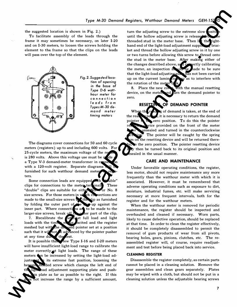
the suggested location is shown in Fig. 2.) To facilitate assembly of the leads through the
frame it may sometimes be necessary, on later 1-20 and on 1-30 meters, to loosen the screws holding the element to the frame so that the clips on the leads will pass over the top of the element.
Fig. 2. Suggested locati on of opening in the base of Type D-6 watthour meter for conn e ct i on l e a d s f rom Types M-30 demand m e t e r timing motors
The diagrams cover connections for SO and 60 cycle
meters (registers) up to and including 600 volts. For 25-cycle meters, the maximum voltage of the register
is 280 volts. Above this voltage use must be made of a Type V-3 demand-meter transformer in connection with a 120-volt register. Separate diagrams will be furnished for such watthour demand meters or registers.
Some connection leads are equipped with "double" clips for connections to the meter terminals. These
"double" clips are suitable for either No. 4 or No. 8 size screws. For those meters in which connections are made to the small-size screws use the clip as furnished
by folding the outer part of the clip up against the inner part. Where connections are to be made to the larger-size screws, break off the outer part of the clip.
7. Recalibrate the meter at full load and light loads with the timing motor excited and the register meshed but with the demand pointer set at a position such that it will not be advanced by the pointer pusher
at any time during the test. It is possible that a few Type 1- 16 and 1-20 meters
will have insufficient light-load range to calibrate the
meter correctly at light loads. The range of these
meters can be increased by setting the light-load ad
justment in its extreme fast position, loosening the
hexagon-headed screw which clamps the left end of
the light-load adjustment supporting plate and push
ing this plate as far as possible to the right. If this does not increase the range by a sufficient amount,
turn the adjusting screw to the extreme slow position until the hollow adjusting screw is released from the threaded stud in the meter base. Then lift the righthand end of the light-load adjustment supporting bracket and thread the hollow adjusting screw in it by one or two turns before allowing this screw to thread onto
the stud in the meter base. After making either of the changes described above, and correctly calibrating
the meter, an inspection should be made to be sure that the light-load adjusting plate has not been carried
up on the current laminations so as to interfere with the rotation of the meter disk.
8. Place the new cover, with the manual resetting device, on the meter, and turn the demand pointer to zero.
RESETTING OF DEMAND POINTER
When the reading of demand is taken, at the end of
the reading period, it is necessary to return the demand pointer to the zero position. To do this the pointer resetting device provided on the front of the meter
cover is unsealed and turned in the counterclockwise direction. The pointer will be caught by the spring arm on the resetting device and will be returned there
by, to the zero position. The pointer resetting device may then be turned back to its original position and resealed in the usual manner.
CARE AND MAINTENANCE
Under favorable operating conditions, the register, less motor, should not require maintenance any more
frequently than the watthour meter with which it is
associated. However, it must be remembered that adverse operating conditions such as exposure to dirt, moisture, industrial fumes, etc. will make servicing
necessary at more frequent intervals, both for the
register and for the watthour meters. When the watthour meter is removed for periodic
maintenance, the register should be inspected and overhauled and cleaned if necessary. Worn parts, likely to cause defective operation, should be replaced at that time. In order to clean the register effectively, it should be completely disassembled to permit the
removal of gum products of wear from all pivots, bearing holes, gears, pinions, clutches, etc. The reassembled register will, of course, require readjust
ment and test before being placed back into service.
CLEANING REGISTER
Disassemble the register completely, as certain parts
cannot be placed in a cleaning solution. Remove the
gear assemblies and clean gears separately. Plates
may be wiped with a cloth, but should not be put in a
cleaning solution unless the adjustable bearing screws
7 www . El
ectric
alPar
tMan
uals
. com
www . El
ectric
alPar
tMan
uals
. com

GEH-1529D Type M-30 Demand Registers, Watthour Demand Meters
are removed, as many solutions will corrode the bear
ings. If plates are immersed, wipe off carefully with a cloth. Keep all springs, fiber, and felt clutch parts out of solvents.
Clean gears and shafts by soaking in a high grade watchmaker's cleaner and by scrubbing with a bristle brush. Rinse parts thoroughly, preferably in chemical
ly pure gasoline, commonly known as benzine. As a
safety measure to reduce fire hazard, it may be desirable to add carbon tetrachloride* to the benzine.
Felt, or fiber parts which have become soaked with oil should be replaced with new parts.
The register dials can be cleaned by using a soft
cloth slightly moistened in water (avoid getting water
on other parts of the register or meter) .
SYNCHRONOUS-MOTOR ROTORS All parts of the G-E Type SG- 1 motor which are
subject to wear are contained in a sealed brass shell
commonly called the "Rotor Unit", and are coated with a grease-type lubricant. When used in the Type
M-30 register, experience indicates the expected life of the rotor unit to be ten years under favorable
operating conditions. The need to replace the rotor unit can be influenced
considerably by adverse operating conditions, such as exposure to extremes of operating temperatures, excess moisture, etc. For example, in an outdoor instal
lation, where the rotor is exposed to direct sunlight and
the temperature extremes are great, the life expectan
cy of the rotor unit will be less than for an installation indoors where room temperature is approximately
70F and temperature variations are small. Therefore,
consideration must be given to the actual operating
conditions in estimating the useful life of a rotor unit. The rotor unit will operate satisfactorily over a
range of ambient temperatures from -30F to + 150F. The minimum temperature is that at which motors in good condition will start and run synchronously after they have been de-energized for a few minutes. In most applications, the motor will continue to run at temperatures somewhat below the minimum temperature specified if there is no power interruption.
The maximum temperature specified is that at
which the motor can operate continuously without
resulting in breakdown of the lubricant. Motors will
withstand for short periods of time, temperatures
somewhat higher than the maximum rated tempera
ture, but they should not be operated continuously
above the maximum value, since oxidation of the lubricant will occur and result in a marked decrease in the life expectancy of the rotor.
If the rotor becomes inoperative, it should be replac
ed with a new rotor.
* Precautions should be raken against roxie vapors when using carbon tetrachloride.
8
For customer servicing of the older Type B-7 rotor,
which is the reoilable type, see Instructions GEH-
1156. For ordering replacement rotors for Types B- 14
(grease-lubricated), B- 12 (oil-lubricated, non-reoilable) , or B-7 (oil-lubricated, both reoilable and non
reoilable) see "G-E Service Plan for Rotor Units"
(Meter and Instrument Handbook, Section 7805, page
5) or contact your nearest General Electric apparatus
sales office.
DISASSEMBLY OF REGISTER The M-30 demand register may be disassembled
from the front or the back, as desired. Disassembly from the Front
If it is necessary to remove only a demand pointer,
scaleplate, front plate, pointer shaft assembly, etc., there is no need for complete disassembly of the regis
ter. It may be dismantled from the front. Steps 1
through 7 of the directions given below cover removal
of parts down to the first intermediate plate.
Disassembly from the Back If a worm wheel shaft assembly, clutch assembly,
pointer-pusher shaft assembly, Geneva mechanism,
etc. is to be removed, the register should be disassembled from the back following steps 8 through 12.
Complete Disassembly When the register is to be disassembled completely
it is recommended that the procedure given below, steps 1 through 12, be followed.
In the following suggested procedure for steps 1
through 7, the register, with its nameplate removed,
should. be resting on the packing bracket or a similar
support to prevent damage to the worm wheel. The description below indicates the sequence for removal of the parts from the front of the register. Numbers referred to are found in Figure 1 and the several mounting plates are shown in Figure 5.
1. Demand pointer. Remove by releasing two set screws located on the pointer hub underneath the center of the dial face, and lifting pointer (22) through the dial opening.
2. Scale. Remove scale ( 30) by loosening four
small screws.
3. Pointers and interval-indicating dial. Remove
kilowatthour pointers ( 3 1) and indicator dial ( 40)
from the end of the shafts. Use a piece or pad of paper
or cloth under the pointer puller to prevent scratching
of the dial. A pair of diagonal cutting pliers, with
cutting edge ground off, makes a good pointer puller
but care must be used not to scar the tapered end of
the shaft.
4. Multiplier plate. Release one round head screw
www . El
ectric
alPar
tMan
uals
. com
www . El
ectric
alPar
tMan
uals
. com

i ...
Type M-30 Demand Registers, Watthour Demand Meters GEH- 1 529D
and slide plate ( 34) from under eccentric pin ( 19). 5. Front plate. Remove three round head screws
from the outside edge of front plate ( 4 7) and the two round head screws on either side of the demand pointer opening. Lift plate.
6. Gear assemblies. Remove pointer gear shaft assemblies ( 4) and interval indicating dial shaft ( 32)
by lifting from the first intermediate plate. Remove ratio gear shaft assembly (20) by lifting
from the second intermediate plate. To remove the interval-indicator-idler-pinion shaft, loosen the set screw on gear and hub assembly (21), below the first intermediate plate. Lift out the idler pinion shaft and withdraw the gear and hub assembly from between
the first and second intermediate plates. 7. Spacers. Lift off three spacers.
In the following steps, 8 through 12, the register should be rested with its back in an upward position.
A simple wooden support made similarly to Figure 3 may be used either with the front of the register assembled or disassembled. If the front of the register
has been disassembled, as in steps 1 through 7 above,
the posts will drop into the holes provided, and the register will rest as indicated by the dotted line. If the front of the register has not been removed the slot provides clearance for the pointer and eccentric stop, and will rest as the phantom line indicates.
Fig. 3. Typical mounting block for supporting register
Disassembly will proceed as follows, with numbers again referring to Figure 1.
8. Motor Assembly. Remove motor (25) by releasing two mounting screws, one on either side of
the motor coils.
9. Sub Plate. Remove three round head screws
and lift off.
a. Back off the adjustable bearings and remove
worm shaft (2) carefully so as not to damage the teeth and pivots.
b. Lift out clutch assembly (5, 6, 7, 8, 9, 10, 1 1) .
Disassemble by loosening the two screws hold-
ing clutch disk ( 7) to the shaft. Reassemble by replacing parts on the shaft and securing the clutch disk with the two set screws so that the hub is located .017 in. from the shaft shoulder as shown in Figure 6 reference (a) .
Note: Whenever register is disassembled and clean
ed all felt friction washers should not be cleaned. If
there is any presence of oil on them, they should be
replaced. c. Lift out worm wheel shaft ( 3).
10. Back Plate. Remove three round head screws
and lift off. This will include clutch lever assembly
(46). The clutch lever may be removed from the plate
by loosening the set screw in the square pivot block to free the pivot shaft for withdrawal from the lever
and block. The adjustable cam follower screw may
be removed after removal of the locking nut. For reassmembly, replace an adjustable screw and nut loosely for later adjustment in assembly. Replace the lever by inserting the pivot shaft through the lever bearing holes and block and secure with the set screw.
a. Lift out sector gear ( 37 ) . b . Lift out the pointer-pusher-and-demand-point
er-shaft assembly (consisting of parts 12, 13, 14, 15, 16, 17, and 18, Fig. 1, and illustrated separately in Fig. 4). This assembly may be
disassembled further by removing the retain
ing ring. This retaining ring must be removed carefully so as not to score, or bend, the shaft.
Fig. 4. Demand pointer shaft assembly with assembly gage block
9 www . El
ectric
alPar
tMan
uals
. com
www . El
ectric
alPar
tMan
uals
. com
GEH-1529D Type M-30 Demand Registers, Watthour Demand Meters
Remove the retaining ring by holding the assembly by the pointer pusher ( 12) and pressing the rounded end of the pointer-pusher shaft
against a wooden block. A uniform pressure (just sufficient to cause the retaining ring to
move) should be applied to the flat end. DO NOT attempt to remove the pointer-dog assembly ( 16) as it is pressed on a knurled section of the pointer-pusher shaft. To re-assemble, place the pointer pusher ( 12)
and the small washer on the pointer-pusher shaft. Gently tap the split retaining washer (using a small driving bar with a clearance hole for the shaft) onto the end of the shaft
squarely to avoid burring the shaft. Leave a clearance of 0.005-in. between the retaining ring and washer. This can be accomplished
by driving the ring down against a 0.005-in. shim. Withdraw the shim after the retaining
ring is in position. Remove the driving-bar
and shaft assembly from the wooden block. Place the three small felt washers on the shaft against the flat end of the pointer dog
Note: Whenever register is disassembled and clean
ed, all felt friction washers should not be cleaned. If
there is any presence of oil on them, they should be replaced.
1 1. Second intermediate plate. Remove two screws
and two register mounting posts and lift off the plate. If the front of the register has not been removed (steps
1 through 7 ), care should be taken when removing these posts not to turn the hexagonal posts below this plate and thus loosen them.
a. Remove two hexagonal spacers (if front disassembly has taken place).
b. Lift out the cam shaft (39). c. Lift out the Geneva mechanism (26, 27, 28,
33, 35, 44, 45). 12. First intermediate plate. Disassembly of regis
ter has been completed. The first intermediate plate can be removed from the block if complete disassembly of the register, steps 1 through 12, has taken place,
or the front portion of the register can be removed as
a unit if only the back disassembly, steps 8 through
12, has been followed.
REASSEMBLY OF REGISTER The M-30 demand register may be reassembled
toward the back or the front as desired.
The dimensions and adjustments referred to below
are for reassembly of registers in the field. They may not necessarily be exactly equivalent to the initial
factory settings, as factory adjustments may be made
with fixtures not adaptable to field work. However,
10
the adjustments covered below will give equivalent
satisfactory operation.
Reassembly toward the Back If the register is being reassembled toward the back,
steps 1 through 4 of the directions given below cover the reassembly of parts from the first intermediate
plate.
Reassembly toward the Front If the register is being reassembled toward the
front, steps 5 through 7 below cover this procedure also starting with the first intermediate plate.
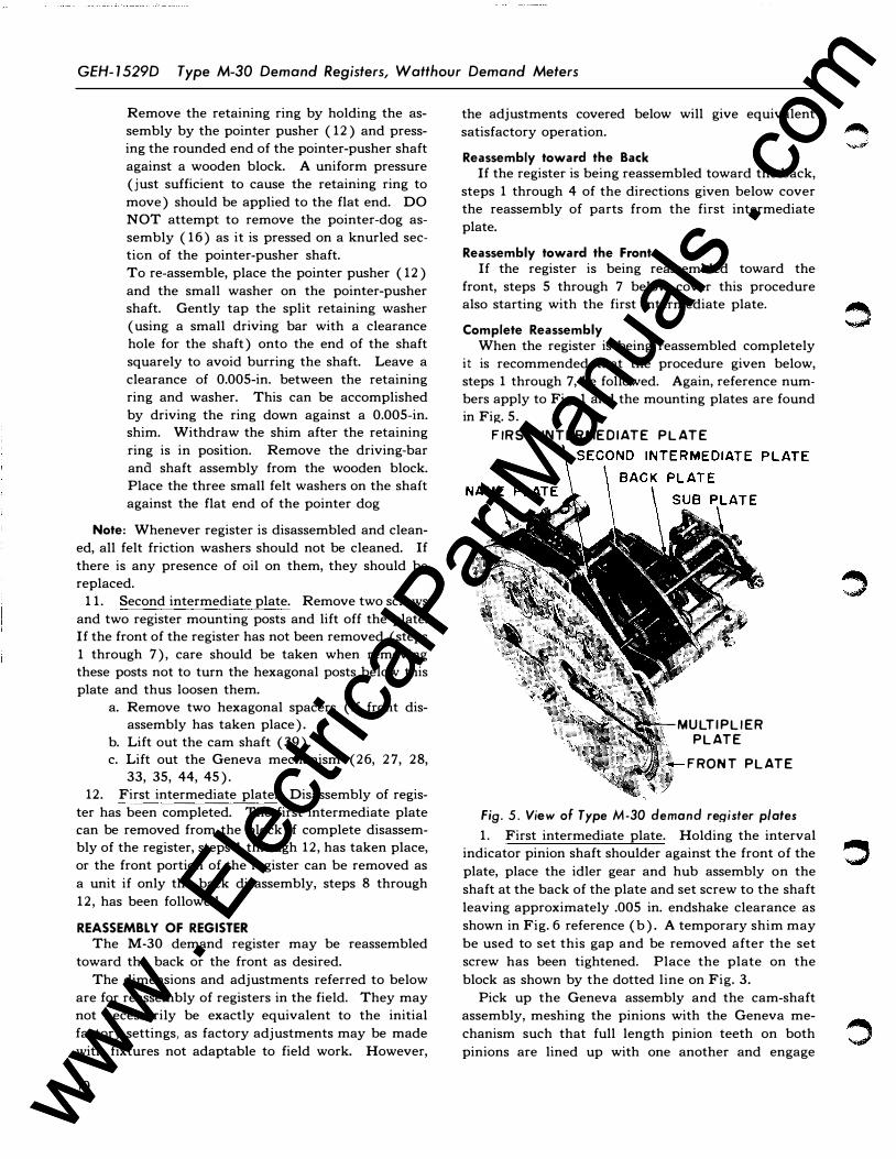
Complete Reassembly When the register is being reassembled completely
it is recommended that the procedure given below, steps 1 through 7, be followed. Again, reference numbers apply to Fig. 1 and the mounting plates are found in Fig. 5.
FIRST INTERMEDIATE PLATE
MULTIPLIER PLATE
FRONT PLATE
Fig. 5. View of Type M-30 demand register plates 1. First intermediate plate. Holding the interval
indicator pinion shaft shoulder against the front of the
plate, place the idler gear and hub assembly on the
shaft at the back of the plate and set screw to the shaft
leaving approximately .005 in. endshake clearance as
shown in Fig. 6 reference (b). A temporary shim may
be used to set this gap and be removed after the set
screw has been tightened. Place the plate on the
block as shown by the dotted line on Fig. 3.
Pick up the Geneva assembly and the cam-shaft
assembly, meshing the pinions with the Geneva me
chanism such that full length pinion teeth on both
pinions are lined up with one another and engage
www . El
ectric
alPar
tMan
uals
. com
www . El
ectric
alPar
tMan
uals
. com
Type M-30 Demand Registers, Watthour Demand Meters GEH- 1 529D
with the transfer gears ( 35) and ( 2 8). Place the Geneva assembly and cam-shaft assembly front pivots in the first intermediate plate.
Place two hexagonal spacers in the plate.
2. Second intermediate plate. Place the second intermediate plate over the studs and gears and fasten with two No. 4-48 screws.
Place and tighten two register mounting posts.
Place the pointer shaft assembly as described under "Disassembly", paragraph 10 (b) together with three friction washers through the second and first intermediate plates. Place reset segment shaft (37) into
the plate. 3. Back Plate. Place back plate and clutch lever
assembly reassembled as described under "Disassembly", paragraph 10, and secure with two No. 4-48 and one No. 3-56 screws. Mesh the reset segment and the pointer-pusher gear as shown in Fig. 7, so that, with the tail of segment gear ( 3 7) resting on reset pin ( 43 ) ,
the pointer-pusher post will be located approximately as shown.
Place the worm-wheel clutch assembly into the second intermediate plate with the reset lever behind the clutch collar as shown in Fig. 7. Place the worm
gear shaft assembly into the bushing of the first plate.
,,
4. Sub Plate. Place the sub plate and the worm shaft assembly over the gears and posts and fasten with three No. 4-48 screws.
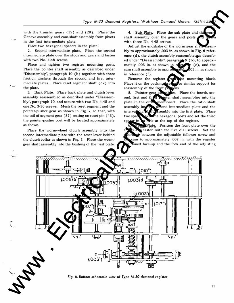
Adjust the endshake of the worm gear shaft assembly to approximately .003 in. as shown in Fig. 6 refer
ence (d), the clutch assembly reassembled as described under "Disassembly", paragraph 9 (b), to approximately .003 in. as shown in reference (e), and the cam shaft assembly to approximately .003 in. as shown
in reference (f). Remove the register from the mounting block.
Place it on the packing bracket or similar support for reassembly of the front portions.
5. Pointer gear assemblies. Place the fourth, sec
ond, first and third pointer shaft assemblies into the plate in the order mentioned. Place the ratio shaft
assembly into the second intermediate plate and the interval dial shaft assembly into the first plate. Place two spacers over the hexagonal posts and set the third spacer in its hole at the top of the register.
6. Front Plate. Position the front plate over the shafts and fasten with the five dial screws. Set the clearance between the adjustable follower screw and the cam to approximately .007 in. with the register
positioned face-up and the fork end of the adjusting
A ll\1@1,1 if I I
I [ �
1111 1111!11 IL' h (.010") (.Oo5')b� [ U�bo3") I Jf [ � U11 I
" � A (.003) d --- 1' ' UIL 111111111 L ,..:!!
,--.,. 1111 e(.003")
II I I II 'vv'
_, � (007") Ill' -�lilm_ � La. (.01711) ' '
"
g_ ffil �� u Jill•· ·• I ll II I IIIIIIIIIDI 11' •1llln I]] pm � •1>1
11 r 11 .,; � . f � ' � - �
CWJ WJ ! I I I '
,, 2�}:chA Ji. OJ C � - I'[{£ 'JTUI.\ \\l (.003 ) � .E3 -, Jl Rl i �'-n/ �
Fig. 6. Bottom schematic view cf Type M-30 demand register
111111
___._
I I
( �I� \..n/
r:::J
11 www . El
ectric
alPar
tMan
uals
. com
www . El
ectric
alPar
tMan
uals
. com

GEH-1529D Type M-30 Demand Registers, Watthour Demand Meters
lever just in contact with the clutch collar as shown in Fig. 6 reference (g). This clearance may require
further adjustment in order to insure that the clutch opens and closes properly in operation.
Press on the four kilowatthour pointers and the interval indicator dial. Slide the multiplier plate un
d.er the eccentric pointer stop and fasten to the front
plate with a round head screw. 7. Scale. Fasten the scale to the front plate with
four small scale plate screws. Insert the demand pointer-shaft assembly through the opening in the
front plate and place it over the pointer shaft leaving
a clearance of approximately .010 in. as shown in Fig. 6 reference (h). A shim may be used for setting this dimension. Secure the demand pointer lightly on the shaft with one set screw preparatory to final
adjustment as covered later under "Adjustments". Place the nameplate on the register and fasten to
the first intermediate plate with a No. 2-64 screw. Place the motor on the two mounting spacers and
fasten by means of the two motor screws.
ADJUSTMENTS
For gear shafts with adjustable bearings, the endshake should be set in accordance with section 4 page 1 1 and as shown in Fig. 6.
For gear shafts with nonadjustable bearings, opera
tion will be satisfactory if the end play is somewhat in excess of these limits as long as the shafts have sufficient clearance to rotate freely;yet, do not have excessive play so that the gears will not mesh properly.
This endshake may range between .002 in. and .025 in.
It is important that the worm-gear and clutch-shaft
�md play should be held to the minimum, because, with excessive play, if the adjustment for mesh of the worm wheel with the disk shaft is set fully in, the
worm gear or the clutch-shaft gear might become disengaged and strip or damage the worm. The worm gears are very delicate and if nicked will cause jerky improper indication. Great care should be used at all times to protect the worm shaft from damage.
There are only five adjustments on the register as
follows:
1. The demand pointer should be over the zero
mark of the scale when it is against pin ( 19). The
pin is eccentric and can be turned until this condition
is obtained.
12
2. To locate properly the pointer dog: a. The pointer-pusher adjusting screw ( 15) in
Fig. 7 should be extending equally on either
side of the post. b. Set the pointer-pusher assembly in its zero
Fig. 7. Back view of position of gears in reset mechanism
position.
c. With the pointer loose on the shaft move the pointer dog so it just contacts the pusher screw.
d. Rotate the pointer against the eccentric pin.
e. Secure the pointer on the shaft maintaining clearance of .0 10 in. Fig. 6, reference (h).
f. Recheck the zero position by moving the pushe!" and the demand pointer up scale and performing the interval reset, returning the point
er pusher to zero position. g. Return the demand pointer to its zero position
and check to see that the dog just rests against the end of the pointer-pusher screw.
h. If an appreciable clearance remains between
the dog and the screw, or the pointer-pusher assembly had been moved by the dog, the demand pointer should be loosened on the shaft and the dog moved slightly to correct the con
dition.
It should be noted that the backlash between the gears (8) and ( 12 ), Fig. 7 and Fig. 1 is, when resetting, taken up in the opposite direction from what it is when the pointer is being advanced. If the zero of the pointer pusher is to be checked by bringing the
pointer back in contact with it after an interval reset,
the pointer must be brought back far enough to take
up the backlash of these two gears. This can be done
without danger of slipping the driving clutch if the
pointer is held lightly, as the increase in pressure re
quired to slip the clutch is quite noticeable.
3. A pointer-pusher screw ( 15) is provided to correlate the zero of the pointer-pusher assembly ( 12, 13,
14) (as established by the interval resetting opera
tion) with the zero of the pointer mechanism ( 16, 17)
as established by the manual pointer resetting action.
www . El
ectric
alPar
tMan
uals
. com
www . El
ectric
alPar
tMan
uals
. com

Type M-30' Demand Registers, Watthour Demand Meters GEH-1529D
If the indication of the register is incorrect when checked as described under "Testing" it can be corrected by turning this screw. Backing this screw out will result in a lower indicated demand and screwing it in will result in a higher indication. (See later section on "Self-Checking Adapter" for further details.)
4. The friction of the pointer can be adjusted by turning the screw (24 ). (See later section on "Fric
tion-Checking Device" for further action.) 5. The clutch friction is adjusted by means of the
nut· ( 1 1 ). (See later section in "Friction-Checking Device" for further action.)
TESTING WAlTHOUR DEMAND METERS
The watthour demand meters should be tested periodically, using the same methods of test employed for the corresponding types of watthour meters. For de
tailed information regarding these methods of test, see the instructions furnished for the watthour meters.
Note that the testing and calibrating of watthour demand meters must be done with the timing motor
excited with correct polarity, the register meshed and
the demand pointer set at a position such that it will not be advanced by the pointer pusher at any time during the test.
TESTING DEMAND REGISTERS
Over-all check of the demand register can be made
by holding a constant load on the watthour meter during one complete time interval. Assuming that the register is of the correct ratio for the meter on which it is mounted, the indicated demand on the
register should then equal the constant load held.
A checking device is available for the Type M-30
register. See page 15 for instructions on this device.
If no special test devices are available, interval reset can be performed electrically by the motor or manually by turning the Geneva mechanism until reset occurs, then pushing the pointer back to some point below the check point and carefully turning the worm
,. wheel a definite number of revolutions. The turning
\.... of the Geneva mechanism during the resetting operation shoud be done at the speed equivalent to the normal rotation of the motor. This is to insure the pointer pusher not overshooting its normal zero posi
tion.
The correct registration can be calculated by using
the first general formula given under "Self-Checking
Adapter" below. In using this method, great care
must be used in holding the worm wheel to prevent
backward rotation during resetting and in advancing
the worm wheel an exact number of revolutions.
DIMENSIONS
Since the dimensions of watthour demand meters are identical with those of corresponding types of watthour meters, except the overall depth, this dimension only is given in Figure 3 1. For more detailed dimensions, see the Instructions covering the corresponding
types of watthour meters.
SELF-CHECKING ADAPTER
CAT. NO. 4151072G1
The Cat. No. 4 15 1072G 1 adapter used with the Type M-30 demand register is the same device as used with the Type M-31 cumulative demand register.
This adapter is designed for mounting on the regis
ter after the register has been moved forward on the meter by using two short adapter studs ( 1- 1 I 8 in. long)
except on meter types VM-4, -7, -9, and - 10 and ISM
-8, -9, - 10, - 1 1, and - 12 and DSM-38, -39, -40, -4 1, -43, and -44 which use four-inch adapter studs. The procedure is to remove the register from the regular regis
ter mounting studs, place the adapter studs onto the
regular studs, and remount the register on the adapter studs. The register so placed on the adapter studs is thereby moved sufficiently forward to permit placing the self-checking adapter on top of the register as
shown in Fig. 8.
After the register is in place, a check could be obtained on its accuracy by allowing the timing motor to run at its normal speed through two or more time intervals. However, since all of the gear trains are now
definitely tied together, if the time train is speeded up,
the demand gear trains will be speeded up correspondingly. Since the indication of the register depends
upon the relative speeds of the demand train and the
Fig. 8. Self-checking adapter Cat. No. 4 1 5 1072G 1 mounted on Type M- 30 demand register using adapter studs
13 www . El
ectric
alPar
tMan
uals
. com
www . El
ectric
alPar
tMan
uals
. com

GEH-1529D Type M-30 Demand Registers, Watthour Demand Meters
time train during the interval the same results will be obtained by advancing the trains manually as by allowing the motor to drive at its normal speed. Therefore, a quick test can be made on the register by advancing the gear trains manually. A handle is provid
ed on the front of the check-device for this purpose.
The complete check can be made manually if the mechanism is turned over slowly as the end of the inter
val is approached. However, to avoid possible errors
due to too rapid manipulation of the device it is recommended that the test be made as follows:
1. Place the checking device on the register making certain that it meshes with the overrunning clutch (38 ) and worm wheel ( 1 ) , Fig. 1.
2. Turn the handle of the adapter clockwise until
the interval indicator shows that the register is about to reset. When the final intermittent advance is about to start, allow the motor to drive the mechanism, until resetting action is completed.
3. Move the demand pointer by hand back into some position below the point on the scale which is to be checked, but not to "zero.
4. Again advance the mechanism manually until it is almost ready to trip and again allow the motor
to complete the operation.
5. Note the reading of the pointer on the scale. The self-checking adapter is equipped with a gear
shift which provides two gear ratios. On class 2 and 4 registers with the manual operating handle pushed in (high check point) , the ratio is such that between interval resets the worm wheel will be turned 5 revolu
tions with the 15-minute interval register and 10 re-
Fig. 9. Friction-ch ecking device Cat. No. 4154935 G 1 with Type M-30 demand register mounted for testing
14
volutions with the 30-minute register. On Class 2 and 4 registers with the manual operating handle pulled out (low-check point ) the worm wheel will be turned 2.5 and 5 revolutions respectively for 15- and 30-min
ute registers.
For checking Class 1 registers this device will check only the low scale point. This check is made by pull
ing out the operating handle and checking in the same manner as with the Class 2 low check point covered
above whereby the worm wheel will be turned 2.5 revolutions in the 15-minute interval register and 5 revolutions in the 30-minute interval register.
In using these devices, the proper accumulated demand (neglecting the multiplier which may appear on
the face of the register ) is given by the following for
mula:
10 x Rev. of Worm Wheel Calculated demand =
T"
I ( . H ) R R
. 1me nt. m r. x eg. atio
Substituting the values given in the preceding paragraphs reduced this to the following simple formulas:
C 1 1
d d d _ 200 (For the high reading )
a cu ate eman - R R . eg. atio
Calculated demand= �00
R �For the low reading )
eg. atio
The calculated scale indications for both high and low points are given in the tabulation below for the
various ratios and classes of overload capacity.
A complete check requires a check of the motor
speed. This can be done with a stop watch by timing
Fig. 10. Friction-ch ecking device Cat. No. 4154935G1 with Type M-30 demand register mounted for testing register supported on watthour m eter
www . El
ectric
alPar
tMan
uals
. com
www . El
ectric
alPar
tMan
uals
. com

Type M-30 Demand Registers, Watt hour Demand Meters GEH- 1 529D
one revolution of the motor output shaft. Reference marks are provided for this purpose on the gear of the overrunning clutch ( 38), Fig. 1, and the motor mounting plate just back of it. This gear makes one revolution per minute for all standard registers.
FRICTION CHECKING DEVICE
CAT. NO. 4154935G1
Successful operation of the Type M-30 register de
pends upon the values of the friction torques necessary
to move the pointer mechanism and to slip the clutch. While these values are not at all critical, it is suggested that they be adjusted to the limits recommended
on page 16.
To aid in checking these friction torques, a friction checking device is available. This device can be used whether the register is mounted on a meter or not. See Figures 9 and 10. It consists of suitable plates
with provisions for mounting the register, a knob attached to a movable calibrated dial and a freely mov
ing shaft carrying a calibration spring arm and pointer.
CALIBRATION OF CHECKING DEVICE
Although each friction-checking device is carefully calibrated and checked before leaving the factory, it is recognized that misuse or rough handling may change
its calibration. Calibrating weights are therefore furnished to allow two points on the scale to be checked
and corrected if necessary. The proper use of these
weights is as follows :
Hang the smaller of the two weights in the groove near the end of the left-hand balance arm (front view) and turn the knob and dial clockwise until the balance
arms are horizontal. The pointer should then point to 50 on the dial.
Remove the small weight and hang the larger weight
in the groove near the end of the right-hand balance arm. Turn the knob and dial counterclockwise until the balance arms are again horizontal. The reading should then be 200 on the opposite side of zero from the point checked before.
Since extreme accuracy in the measurement of Type M-30 register friction values is not necessary, it is suggested that the position of the spring be changed only when the calibration readings are more than plus or
minus five per cent from the values given on page 16.
USE AS LABORATORY DEVICE
When the device is to be used in the shop for check
ing registers not on meters, the following procedure
may be used after having determined that the device
pointer is free in its bearings and rests over zero on the
dial. See Fig. 9.
Pointer Friction
a. Turn the device knob counterclockwise until the device pointer is at the bottom of the frame at its point of extreme counterclockwise travel.
b. Move the demand pointer on the register to
full scale manually and return it to approximately scale zero.
c. Slip the register behind the two supporting
tabs at the top of the friction-checking device and rest the register on the supporting plate
against the covered stops at the bottom of the device.
d. On Type M-30 registers with serial numbers
above 1177 163, turn the checking device knob clockwise very slowly until the demand point
er moves and take the reading on the dial when the pointer again comes to rest. However, on
registers with serial numbers 1 177 163 and below, turn the knob clockwise very slowly until
the demand pointer moves, and take the reading on the dial just as the pointer starts to move. Repeat one of the above methods until the demand pointer has moved to the right end of
the register scale. Four or five readings should be obtained during the travel of the pointer from one end of the scale to the other.
e. Pointer friction values should check between
15 and SO mmg. f. The friction on the pointer can be adjusted by
means of screw (24) Fig. 1. This adjusting screw is locked in position by a set screw. Turning in the adjusting screw will increase the friction; backing it out will decrease the friction.
Clutch Friction
Two methods of checking clutch friction are covered below. The first Method A, is the more accurate and is used in the initial setting at the factory. Adjusting the clutch friction by either method will give equivalent final results in the clutch setting.
In Method A, the reading of the testing device equals the total clutch friction minus the pointer friction and minus the gear and bearing frictions; which
is the reserve friction of the clutch.
In Method B, the reading of the testing device
equals the total clutch friction plus the pointer friction
and plus the gear and bearing friction; which is the
total torque necessary to slip both the pointer and
clutch and to overcome the associated gear and bear
ing frictions. Since, in this method, the testing device
reading is greater than in Method A, the pointer gear
1 5 www . El
ectric
alPar
tMan
uals
. com
www . El
ectric
alPar
tMan
uals
. com
GEH-1529D Type M-30 Demand Registers, Watthour Demand Meters
Method A train is subjected to greater gear and bearing pressures
than in Method A or in actual use; and, consequently,
the gear and bearing friction is several times greater. Thus, method B is less accurate because of the abnormal influence of the higher gear and bearing friction.
The friction value measured by this method is the
available reserve clutch driving torque over and above the pointer and clutch and other frictions in the gear train.
a. By turning the device knob, position the de-
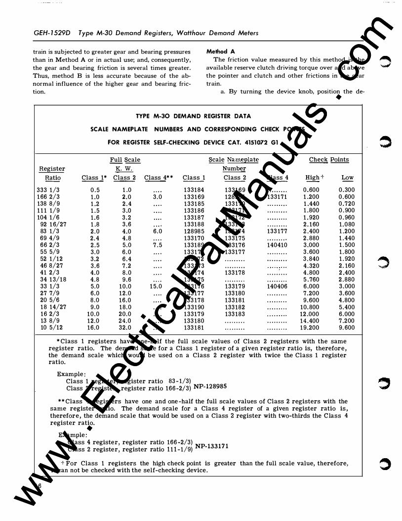
TYPE M-30 DEMAN D R EGISTER DATA
SCALE NAMEPLATE N UMBERS AND CORRESPONDING CHECK POI NTS
FOR REGISTER SELF-CHECKING DEVICE CAT. 4151 072 G1
Full Scale Scale Nameplate Check Points -- --
Register K. W. Number
Ratio Class 1* Class 2 Class 4* * Class 1 Class 2 Class 4 High -1- Low -
333 1/3 0 . 5 1 .0 . . . . 1 33184 133169 . . . . . . . . . 0 , 600 0 . 300 1 66 2/3 1 .0 2 .0 3 .0 1 3 3 1 69 128985 133171 1 .200 0 . 600 138 8/9 1 .2 2 . 4 . . . . 133185 133 170 · · · · · · · · · 1 .440 0 .720 1 1 1 1/9 1 . 5 3 .0 . . . . 133186 133171 . . . . . . . . . 1 .800 0 . 900 104 1/6 1 . 6 3 . 2 . . . . 133187 133172 . . . . . . . . . 1 . 920 0 . 960
92 1 6/27 1 .8 3 .6 . . . . 133188 133173 . . . . . . . . . 2 . 160 1 .080 83 1/3 2 . 0 4 .0 6 .0 12898 5 133174 133 177 2 .400 1 .200 69 4/9 2 . 4 4 . 8 . . . . 133 170 133175 · · · · · · · · · 2 . 880 1 .440 66 2/3 2 . 5 5 .0 7 . 5 133189 1 33176 140410 3 .000 1 . 500 55 5/9 3 .0 6 . 0 . . . . 1 3 3 1 7 1 1 33177 . . . . . . . . . 3 . 600 1 . 800 52 1/12 3 .2 6 . 4 . . . . 133 172 . . . . . . . . . . . . . . . . . . 3 . 840 1 . 920 46 8/27 3 . 6 7 . 2 . . . . 1 3 3 1 73 . . . . . . . . . 4 . 320 2 . 160 41 2/3 4 .0 8 . 0 . . . . 133 174 133 178 . . . . . . . . . 4 . 800 2 .400 34 1 3/18 4 .8 9 . 6 . . . . 133175 . . . . . . . . . · · · · · · · · · 5 . 760 2 .880 33 1/3 5 .0 10.0 1 5.0 133176 133179 140406 6 .000 3 . 000 27 7/9 6 .0 12 .0 . . . . 133 177 133 180 . . . . . . . . . 7 .200 3 . 600 20 5/6 8 .0 16 .0 . . . . 133 178 133181 . . . . . . . . . 9 . 600 4 . 800 18 14/27 9 .0 18 .0 . . . . 133190 133 182 · · · · · · · · · 10. 800 5 .400 16 2/3 10 .0 20.0 . . . . 133179 133 183 · · · · · · · · · 12 .000 6 .000 13 8/9 12 .0 24 .0 . . . . 133 180 · · · · · · · · · . . . . . . . . . 14 .400 7 .200 10 5/12 16.0 32.0 . . . . 133 181 . . . . . . . . . · · · · · · · · · 1 9 .200 9. 600
* Class 1 registers have one-half the full scale values of Class 2 registers with the same
16
register ratio. The demand scale for a Class 1 register of a given register ratio is, therefore, the demand scale which would be used on a Class 2 register with twice the Class 1 register ratio.
Example : Class 1 register, register ratio 83 - 1/3) Class 2 register, register ratio 166 -2/3) NP-
128985
** Class 4 registers have one and one -half the full scale values of Class 2 registers with the same register ratio. The demand scale for a Class 4 register of a given register ratio is , therefore, the demand scale that would be used on a Class 2 register with two-thirds the Class 4 register ratio.
Example : Class 4 register, register ratio 166 -2/3) NP 133 17 1 Class 2 register, register ratio 1 1 1 -1/ 9)
-
-� For Class 1 registers the high check point is greater than the full scale value, therefore, it can not be checked with the self-checking device.
�
www . El
ectric
alPar
tMan
uals
. com
www . El
ectric
alPar
tMan
uals
. com
Type M-30 Demand Registers, Walthour Demand Meters GEH-1529D
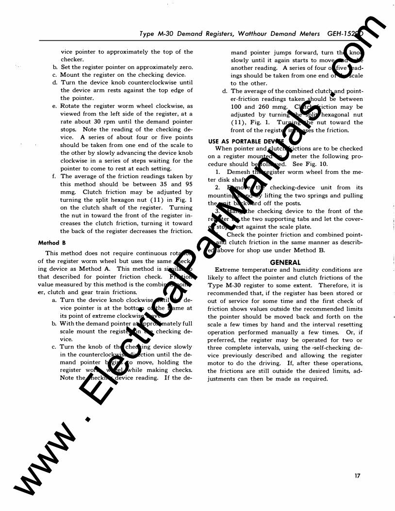
vice pointer to approximately the top of the checker.
b. Set the register pointer on approximately zero. c. Mount the register on the checking device.
d. Turn the device knob counterclockwise until the device arm rests against the top edge of the pointer.
e. Rotate the register worm wheel clockwise, as viewed from the left side of the register, at a rate about 30 rpm until the demand pointer stops. Note the reading of the checking device. A series of about four or five points
should be taken from one end of the scale to the other by slowly advancing the device knob clockwise in a series of steps waiting for the pointer to come to rest at each setting.
f. The average of the friction readings taken by
this method should be between 35 and 95 mmg. Clutch friction may be adjusted by turning the split hexagon nut ( 1 1) in Fig. 1 on the clutch shaft of the register. Turning the nut in toward the front of the register increases the clutch friction, turning it toward the back of the register decreases the friction.
Method B
This method does not require continuous rotation
of the register worm wheel but uses the same checking device as Method A. This method is similar to
that described for pointer friction check. Friction value measured by this method is the combined pointer, clutch and gear train frictions.
a. Turn the device knob clockwise until the de
vice pointer is at the bottom of the frame at
its point of extreme clockwise travel. b. With the demand pointer at approximately full
scale mount the register on the checking de
vice. c. Turn the knob of the checking device slowly
in the counterclockwise direction until the demand pointer begins to move, holding the register worm wheel while making checks. Note the checking device reading. If the de-
mand pointer jumps forward, turn the knob slowly until it again starts to move and take another reading. A series of four or five readings should be taken from one end of the scale to the other.
d. The average of the combined clutch and point
er-friction readings taken should be between 100 and 260 mmg. Clutch friction may be adjusted by turning the split hexagonal nut ( 1 1), Fig. 1. Turning the nut toward the
front of the register increases the friction.
USE AS PORT ABLE DEVICE When pointer and clutch frictions are to be checked
on a register mounted on a meter the following pro
cedure should be followed. See Fig. 10.
1. Demesh the register worm wheel from the meter disk shaft.
2. Remove the checking-device unit from its
mounting stand by lifting the two springs and pulling the unit backward off the posts.
3. Hang the checking device to the front of the register by the two supporting tabs and let the covered stops rest against the scale plate.
4. Check the pointer friction and combined pointer and clutch friction in the same manner as describ
ed above for shop use under Method B.
GENERAL Extreme temperature and humidity conditions are
likely to affect the pointer and clutch frictions of the Type M-30 register to some extent. Therefore, it is recommended that, if the register has been stored or out of service for some time and the first check of friction shows values outside the recommended limits the pointer should be moved back and forth on the scale a few times by hand and the interval resetting
operation performed manually a few times. Or, if preferred, the register may be operated for two or three complete intervals, using the -self-checking device previously described and allowing the register motor to do the driving. If, after these operations, the frictions are still outside the desired limits, adjustments can then be made as required.
17 www . El
ectric
alPar
tMan
uals
. com
www . El
ectric
alPar
tMan
uals
. com
GEH- 1 529D Type M-30 Demand Registers, Watthour Demand Meters
TYPE IM-50
Variations exist in the construction of the Type 1-50 watthour meter which necessitate a change in the me
thod of connecting the motor leads to the watthour
meter terminals. It will also be necessary to use the two special
mounting studs (supplied in an envelope with each
register) when mounting the demand register on to
the watthour meter register supporting posts.
Except for the variations listed, the method of conversion remains the same for the Type 1-50 watthour meter as for any other meter listed in the Introduction of this book.
The actual differences in the method of connecting the motor leads to the watthour-meter terminals are as follows :
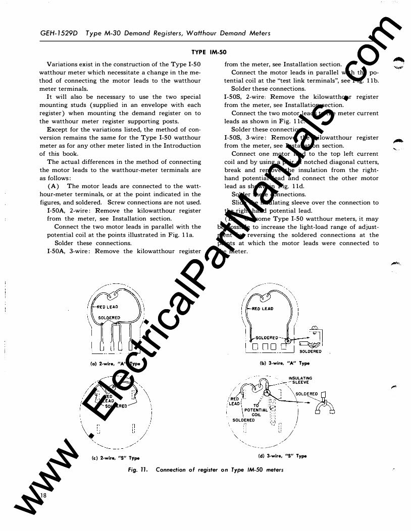
(A) The motor leads are connected to the watthour-meter terminals, or at the point indicated in the
figures, and soldered. Screw connections are not used.
I-50A, 2-wire : Remove the kilowatthour register from the meter, see Installation section.
Connect the two motor leads in parallel with the
potential coil at the points illustrated in Fig. l la.
Solder these connections. I-50A, 3-wire : Remove the kilowatthour register
(a) 2-wire, "A" Type
from the meter, see Installation section. Connect the motor leads in parallel with the po
tential coil at the "test link terminals", see Fig. l lb. Solder these connections.
I-50S, 2-wire: Remove the kilowatthour register
from the meter, see Installation section.
Connect the two motor leads to the meter current leads as shown in Fig. l lc.
Solder these connections. I-50S, 3-wire : Remove the kilowatthour register from the meter, see Installation section.
Connect one motor lead to the top left current
coil and by using a pair of notched diagonal cutters, break and remove the insulation from the righthand potential lead and connect the other motor lead as shown in Fig. l ld.
Solder these connections. Slide the insulating sleeve over the connection to
the right-hand potential lead. (B) On some Type 1-50 watthour meters, it may
be possible to increase the light-load range of adjustment by reversing the soldered connections at the
points at which the motor leads were connected to
the meter.
\ )
UJ D D J�
(b) 3-wire, "A" Type
INSULATING , - S LEEVE
/' " '\ S'
OLD�E ED 1./ df' n \
rrf ::: ':� ----;,....._� POTENTIAL ��� }
COIL � : : : SOLDERED l:.J: ,(� 1 _ _: :-; 1
'" : J u,/' - -- - - __ ___..--
(c ) 2-wire, "S" Type (d) 3-wire, "S" Type
1 8
Fig. l l . Connedion o f register o n Type IM-50 meters
www . El
ectric
alPar
tMan
uals
. com
www . El
ectric
alPar
tMan
uals
. com
Type M-30 Demond Registers, Wotthour Demond Meters GEH- 1 529D
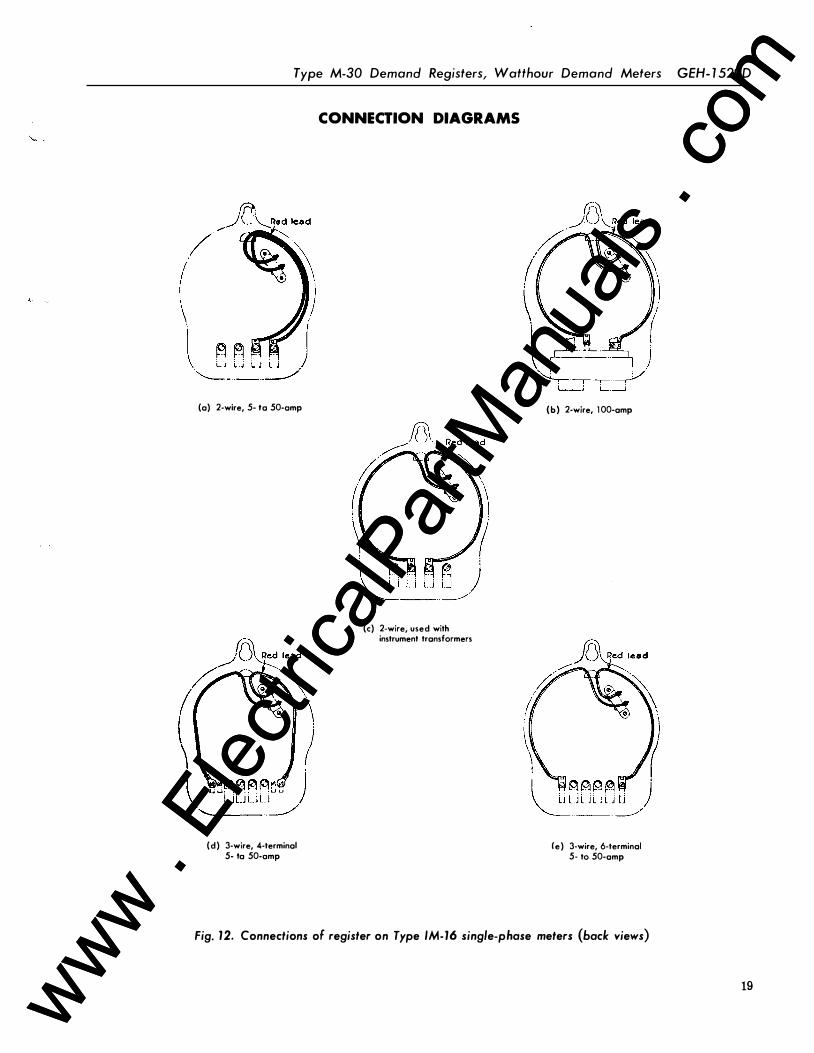
(a) 2-wire, 5- Ia 50-amp
(d) 3-wire, 4-terminal 5- Ia 50-amp
CONNECTION DIAGRAMS
(c) 2-wire, used with instrument transformers
(b) 2-wire, 1 00-amp
(e) 3-wire, 6-terminal 5- to 50-amp
Fig. 12. Connections of register on Type IM-16 single-phase meters (back views)
19 www . El
ectric
alPar
tMan
uals
. com
www . El
ectric
alPar
tMan
uals
. com
GEH- 1 529D Type M-30 Demand Registers, Watthour Demand Meters
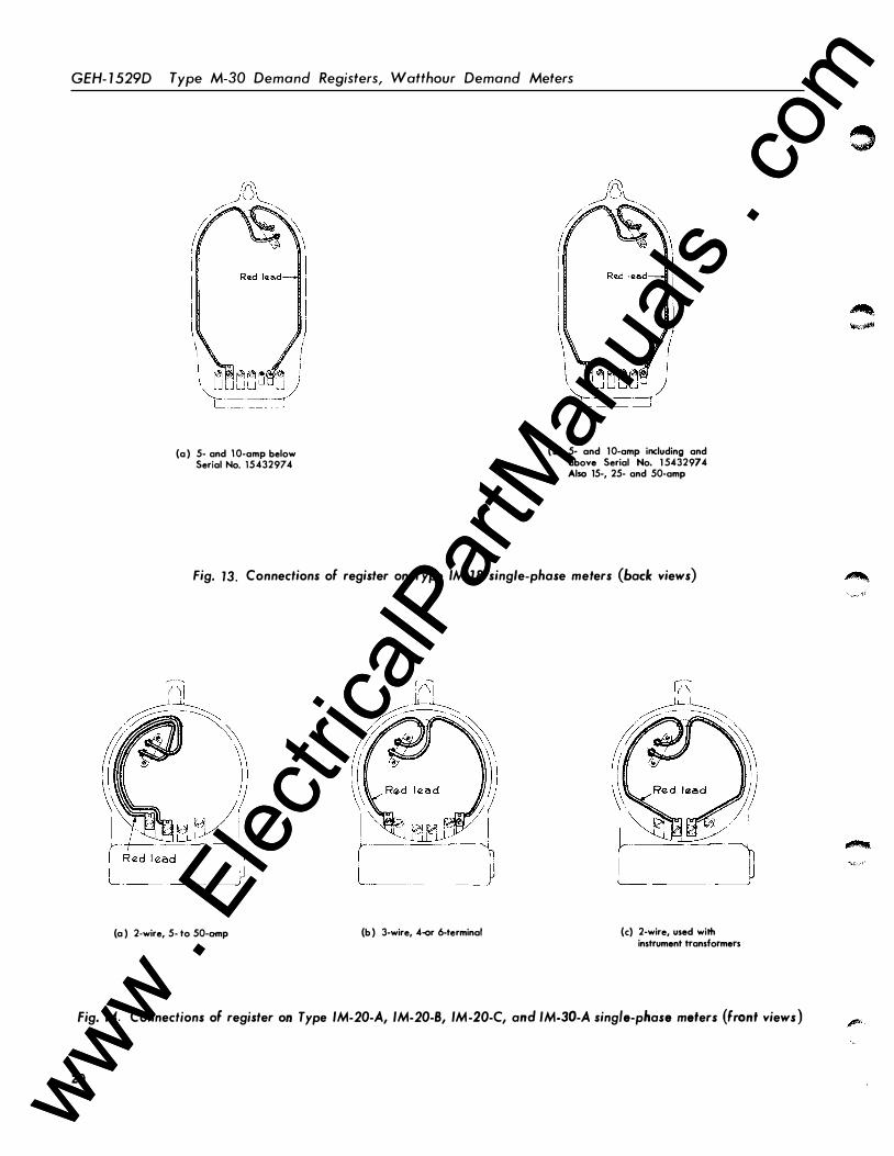
(a ) 5- and 1 0-amp below Serial No. 15432974
(b) 5- and 1 0-amp including and above Serial No. 1 5432974 Also 15-, 25- and 50-amp
Fig. 13. Connections of register on Type IM-18 single-phase meters (bade views)
(a ) 2-wire, 5- to 50-amp (b ) 3-wire, 4-or 6-terminal
'---- · ---
(c) 2-wire, used with instrument transformers
Fig. 14. Connections of register on Type IM-20-A, IM-20-8, IM-20-C, and IM-30-A single-phase meters (front views )
20
0
www . El
ectric
alPar
tMan
uals
. com
www . El
ectric
alPar
tMan
uals
. com
I I
I \
I ; I \
I I
Type M-30 Demand Registers, Watthour Demand Meters GEH-1529D
r l 1, "-�,r I "� J I
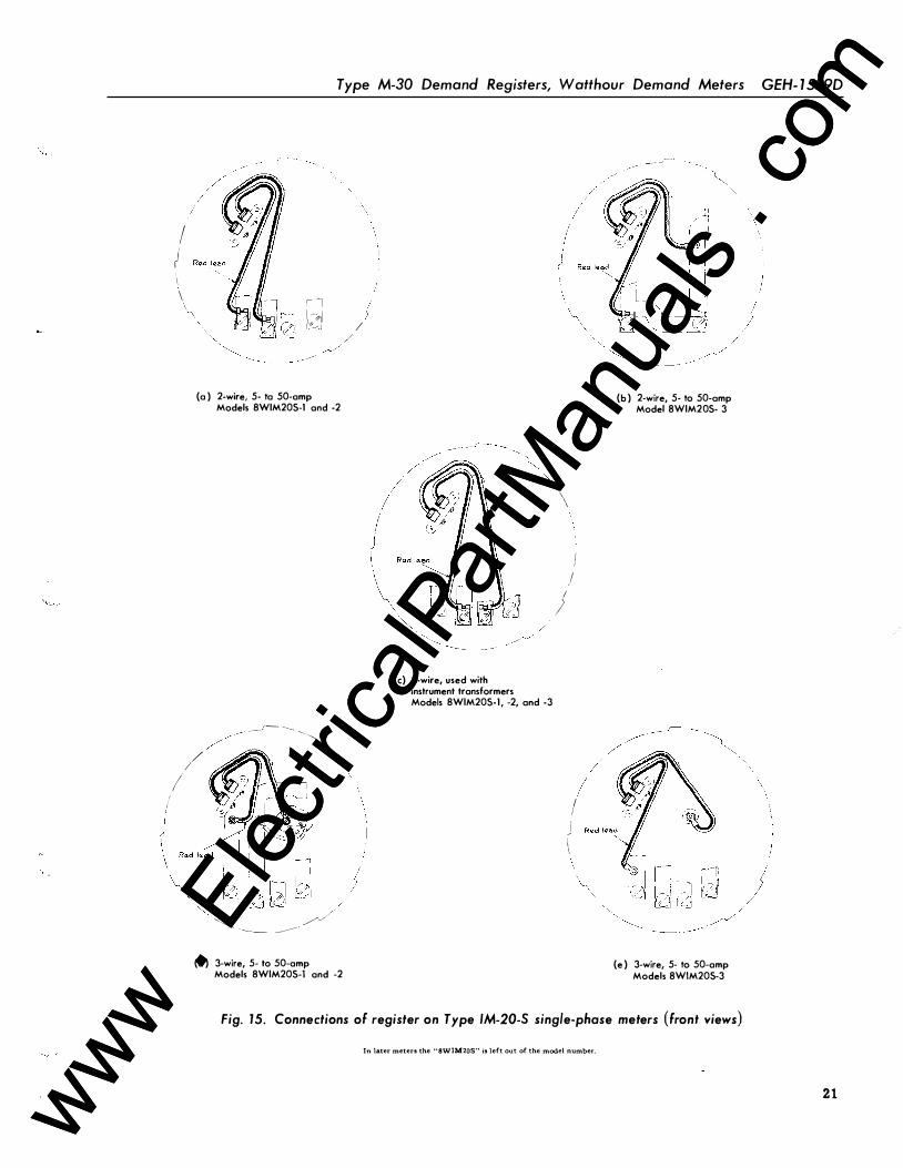
{a ) 2-wire, 5- ta 50-amp Models 8WIM20S-1 and -2
� _____ ,� -----
� � /
/
/ ""
) � / / � --- ---------{d ) 3-wire, 5- to 50-amp
Models 8WIM20S-1 and -2
{c) 2-wire, used with instrument transformers Models 8WIM20S-1 , -2, and -3
i I
(
\
I )
I /
j \ I
__ _,�-
/
{b ) 2-wire, 5- to 50-amp Model 8WIM20S- 3
/ �
{e ) 3-wire, 5- to 50-amp Models 8WIM20S-3
Fig. 15. Connections of register on Type IM-20-S single-phase meters (front views) In later meters the "8WTM20S" is left out of the model number.
/
2 1 www . El
ectric
alPar
tMan
uals
. com
www . El
ectric
alPar
tMan
uals
. com

GEH-1529D Type M-30 Demand Registers, Watthour Demand Meters
22
/ I I
\
(a ) 2-wire, 5- to 50-amp
Red lead
(b) 2-wire, used with instrument transformers below Serial No. 20360858
\\ il u
n u
n u '
'" '� ,
- ----- ·- - - --- -
(c) 2-wire, used with instrument transformers Serial No.20360858 andabove
(d ) 3-wire, 5- to 50-amp
Fig. 16. Connections of register on Type IM-30-S single-phase meters (front views)
L , _ _ _ _ _ _j (a ) Type VM-2-A
5- to 50-amp (b ) Type VM-2-S
5- to 50-amp
Fig. 17. Connections of register on Type VM-2 meters (front views)
www . El
ectric
alPar
tMan
uals
. com
www . El
ectric
alPar
tMan
uals
. com
Type M-30 Demand Registers, Watthour Demand Meters GEH- 1 529D
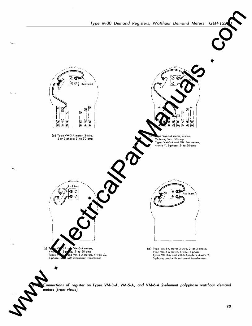
(a ) Type VM-3-A meter, 3-wire, 2-or 3-phase; 5- to 50-amp
(c) Types VM-3-A and VM-6-A meters, 4-wire 6, 3-phase; 5- to 50-amp Types VM-3-A and VM-6-A meters, 4-wire 6. 3-phase; used with instrument transformer
(b ) Type VM-3-A meter, 4-wire, 2-phase; 5- to 50-amp Types VM-3-A and VM 5-A meters, 4-wire Y, 3-phase; 5- to 50-amp
l ! I
L �_. _ _j (d ) Type VM-3-A meter 3-wire, 2- or 3-phase;
Type VM-3-A meter, 4-wire, 2-phase; Types VM-3-A and VM-5-A meters, 4-wire Y, 3-phase; used with instrument transformers
Fig. 1 8. Connections of register on Types VM-3-A, VM-5-A, and VM-6-A 2-element polyphase watthour demand meters (front views)
23 www . El
ectric
alPar
tMan
uals
. com
www . El
ectric
alPar
tMan
uals
. com
GEH- 1 529D Type M-30 Demond Registers, Walthour Demond Meters
24
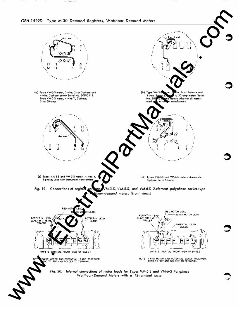
(a ) Type VM-3-S meter, 3-wire, 2- or 3-phase and 4-wire, 2-phase below Serial No. 201034 1 3 Type VM-5-S meter, 4-wire Y , 3'-phase; 5- to 50-amp
� \ 'i
iu 'I.J// /
(c) Types VM-3-S and VM-5-S meters, 4-wire Y, 3-phase; used with instrument transformers
I rn lJ
I
[J J (b ) Type VM-3-S meter, 3-wire, 2- or 3-phase and
4-wire, 2-phase. For 5- to 50-amp meters Serial No. 201 1 1 350 and above. Also far all meters used with instrument transformers
0 I /
(d ) Types VM-3-S and VM-6-S meters, 4-wire 6., 3-phase; 5- to 50-amp
Fig. 1 9. Connections of register on Types V M-3-S, V M-5-S, and V M-6-S 2-elemenf polyphase socket-type
watthour-demand meters (front views)
RED MOTOR LEAD
BLACK MOTOR LEAD •
VM- 5 - S ( PARTIAL FRONT VIEW OF BASE )
NOTE: TWIST MOTOR AND POTENTIAL LEADS TOGETHER, BEND TO 90• AND SOLDER TO TERMINAL
RED MOTOR LEAD BLACK MOTOR LEAD
VM-6 - S ( PARTIAL FRONT VIEW OF BASE )
NOTE TWIST MOTOR AND POTENTIAL LEADS TOGETHER, BEND TO 90" AND SOLDER TO TERMINA L .
Fig. 20. Infernal connections of motor leads for Types VM-5-S and VM-6-S Polyphase Watthour - Demand Meters with a 1 3-terminal base.
0
www . El
ectric
alPar
tMan
uals
. com
www . El
ectric
alPar
tMan
uals
. com
Type M-30 Demand Registers, Watthour Demand Meters GEH- 1 529D
------- ------- -// ------- -. '\ I , ���Red lead�\
i • I i • ! . I I . . I I . . I I . . I I . , I \ ' , I I , . I I . . I I . :__ _ _ _ _ _ _ _ _ _ !
/ �od I<Zad
"'-., \ I I
- - -- � I I� !_ ' I
_: ll I ll 1 1l ,� -, 1c:l � 1 11 ( rLlli��-� ��
L �-==-d
/ /
I ( I I L_ -� ____j
)
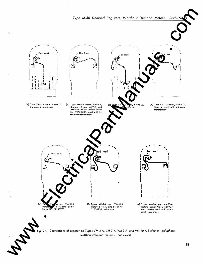
(a ) Type VM-4-A meter, 4-wire Y, (b ) Type VM-4-A meter, 4-wire Y, 3-phase; 5- to 50-amp 3-phase; Types VM9-A and
VM-10-A meters below Serial No, 2 1 650733; used with instrument tronsfor mers
(c) Type VM-7-A meter, 4-wire /':,., 3-phase; 5- to 50-amp
(d ) Type VM-7-A meter, 4-wire /':,., 3-phase; used with instrument transformers
/ ----- - - ----.............. I '\
I Red leed \
i i ! j I I i i i I \ j \ I i i I i i _ _ _ _ _ _ _ _ _ _ _ j
(e ) Types VM-9-A and VM-10-A meters, 5- to 50-amp below Serial No. 2 1 650733
-----/_.,..- -' " / ' ( Red lead \ 1 � I
ihi I I I I
l ! \ I I I I I I I I I ' I
L _ _ _ _ _ _ _ _ j
(f) Types VM-9-A and VM-10-A meters, 5- to 50-amp Serial No. 2 1 650733 and above
(g ) Types VM-9-A and VM-10-A meters, Serial No. 2 1 650733 and a bave; used with instrument transformers
Fig. 2 1 . Connections of register on Types VM-4-A, VM-7-A, VM-9-A, and VM- 1 0-A 3-element polyphase
watthour-demand meters (front views)
25 www . El
ectric
alPar
tMan
uals
. com
www . El
ectric
alPar
tMan
uals
. com

GEH - 1 529D Type M-30 Demand Registers, Watthour Demand Meters
(a ) .4-wire, 2-phase, 5- to 75-amp
(d) 3-wire, 2- or 3-phase, 5- to 75-amp
(b ) 3-wire, 2- or 3-phase 100- to 1 50-amp
(e) .4-wire, 3-phase, used with instrument transformers
(c) .4-wire, 3-phase, 5- to 75-amp
(f) 3-wire, 2- or 3-phas" and .4-wire, 2-phase, used with instrument transformers
Fig. 22. Connections of register on Types DM-6 and DM-7 meters (back views)
26 www . El
ectric
alPar
tMan
uals
. com
www . El
ectric
alPar
tMan
uals
. com

Type M-30 Demand Registers, Watthour Demand Meters GEH- 1 529D
la) 3-wire, 2- or 3-phase, 5- Ia 50-amp below Serial No. 16726889.
(b) 3-wire, 2- or 3-phase, 5- to 50-amp including and above Serial No. 167268119
(c) 3-wire, 2- or 3-phase, and 4-wire, 2-phase; used with instrument transformers
/ i I ! i '
! i
/. /-::
� � � � "' "' u u'l� � 1,,=,=.::.=-.,=:J
(d ) 4-wire, 2-phase, 5- to 50-amp
Fig. 23. Connections of register on Type DM-14 meters, 3-wire, 2- or 3-phase and 4-wire, 2-phase (back views)
(a ) 5- to 50-amp (b ) With transformers
Fig. 24. Connections of register on Type DM-14 meters,
4-wire n, 3-phase (back views)
Fig. 25. Connections of register on Type /SM-8, -9 DSM- 1 9, ·20, -34, and -35 meters (front view)
27 www . El
ectric
alPar
tMan
uals
. com
www . El
ectric
alPar
tMan
uals
. com

GEH- 1 529D Type M-30 Demand Registers, Watthour Demand Meters
(
(a ) 5- to 50-amp (b ) With transformers
Note..-� For 5- to 50-amp (self-contained) ratincs the connections apply only to those meters in which the terminal arrana;ement is such that the 3-wire current coil on the bottom element is connected to the two outside left and two outside ria:ht current terminab, i.e .• meters above Serial No. 16976134.
Fig. 27. Connections of register on Type DM-15 meters, 4-wire .6, 3-phase (back views)
28
Fig. 26. Connections of register on Type DM-15 meters,
4-wire Y, 3-phase (back views)
Red l<zad Red lozad
(a ) 5- to 25-amp, incl. (b) 50-amp
Note: -These connections apply only to those meters which have the 230-volt �otential coil on the bottom element. Connections for these meters in ratin&s for use with transformers are the same as Type DM-15, 4-wire Y, 3-phase meters with transformers. �e Fi&. 24(b)
www . El
ectric
alPar
tMan
uals
. com
www . El
ectric
alPar
tMan
uals
. com

.....
...
/ ;..f ' I 1 I I
' ' · '
Type M-30 Demand Registers, Watthour Demand Meters GEH- 1 5290
' .
�· r I
R�d l11.ad R�d laad
- -'
(a ) 5- to 50-amp (b ) With transformers
Fig. 28. Connections of register on Type DM-15 totalizing meters for one 3-wire, 3-phase circuit and one 3-wire, \, single-phase circuit (buck views)
- - - - -( I
' 1 - 1&11<1
I I
I I
I I
I I
I I I I
-----, I I I i I
I I
I ' I '
l I I
I I
I j
'-----��d��b� p r· n r· • l,.__.l L_j L-.JL_J
Fig. 29. Connection of register on Types DSM-38, -40, and -43, meters
(front view)
Fig. 30. Connection of register on Types DSM-39, -4 1 , and -44,
meters (front view)
Fig. 3 1 . Connection of register on Types ISM- 1 0, - 1 1 , and - 1 2,
meters (front view)
29 www . El
ectric
alPar
tMan
uals
. com
www . El
ectric
alPar
tMan
uals
. com

GEH- 1 529D Type M-30 Demand Registers, Watthaur Demand Meters
' 37" ------- - -- 7 - MAX ------I 6 4 I I 7 " I �� --! 32 :
I
(a) Type IM-50-A
----1 I I
--8�-"MAX-l
(b) Type IM-50-S
(c) Type I SM-S, -9, and - 1 0, DSM- 1 9 or DSM-20 (d) Type ISM- 1 2, DSM-38, - 43 01 DSM-44 (e) Type ISM- 1 1 , DSM-39 and -40 or DSM-4 1
- "A" MAX -
(fl All other "A" Types (g) All other "S" Types
TYPES IM - 1 6 IM -18 IM -2 0 -A
IM-20 -C* IM -20 -S IM -30 -A IM -30 -S IM-20 -B
AMPS 5-10 1 5-50 5-10 1 5 -2 5 2 . 5- 50 2 . 5 - 50 2 . 5-50 2 . 5 -50 5 - 50
MAX. "A" DIM . 7 -1/32 7 -7/16 7 -3/8 7 - 1 7/32 7 -1 1/16 9-1/4 10-1/4 t 7 - 1 1/16 10-1/4 t (INCHES)
DSM -6 VM -3-A VM -3-S VM -4-A
TYPES DM-14 DM-1 5 VM-2 -A VM-2 -S VM -5-A VM -5-S VM -7 -A DSM -7
VM -6-A VM -6 -S VM -9-A VM - 10 -A
AMPS 5-25 50 - 1 50 5-50 5 - 50 5-50 5-50 2 . 5 -50 2 . 5-50 2 . 5 -50 MAX. "A" DIM . 7 -7/16 8 -3/8 7 -5/8 7 -23/32 9-9/32 l l - 13/32 t 9 -3/8 13-7/16 t 8 -23/32
(INCHES)
(For additional dimensions see Instructions for corresponding types of wotthour meters. )
tThis dimension is over-all and includes the meter socket. Note that the depth of the socket and the over-all dimension of meter and socket vary slightly
with the rating of the socket. *This dimension is over-all and includes the protector case.
Fig. 32. Dimensions of watthour demand meters
30 www . El
ectric
alPar
tMan
uals
. com
www . El
ectric
alPar
tMan
uals
. com

c
Type M-30 Demand Registers, Watthour Demand Meters GEH- 1 529D
NOTES
3 1 www . El
ectric
alPar
tMan
uals
. com
www . El
ectric
alPar
tMan
uals
. com

W H E N Y O U N E E D S E R V I C E IF YOU NEED TO REPAIR, recondition, or rebuild any electric apparatus, a G-E service shop near you is available d a y a n d night, seven days a week, for work i n t h e shops or on your premises. Latest factory methods a n d genuine G-E renewal parts are used to maintain the original performance of your G-E equipment. For ful l information a bout these services, contact the nearest service shop or sales office listed below:
A P P A R A T U S S E RVI C E S H O P S Appleton, Wise. . Midway Industrial Area,
County Trunk, "P" Atlanta-Chamblee, Ga. . . . 4639 Peachtree
Indus. Blvd. Baltimore 30, Md. . . . . 920 E. Fort Ave. Boston-Medford 55, Mass.Mystic Valley Pkwy. Buffalo 1 1 , N. Y . . . . . . . . . 3 1 8 Urban St. Charleston 28, W. Vo . . 306 MacCorkle Ave., S.E. Charlotte, N. C. . . 2328 Thrift Rood Chicago 32, Ill . . . . . . . . . . . 4360 W. 47th St. Cincinnati 2, Ohio . . . . . . 444 W . Third St. Cleveland 4, Ohio . . . . . 4966 Woodland Ave. Columbus 23, O hi o . . . . . 2 1 28 Eakin Rd. Dallas 9, T e xas . . . . . . 3202 Manor W a y Davenport-Bettendorf, I a . . . I 039 State St. Decatur, Ill. . . . 2225 E. logon St. Denver 5, Colo. . . . . . 3353 Lorimer St. Detroit 2, Mich. . 5950 Third Ave. Houston 20, T e xas . . 5534 Hervey Wilson Drive Indianapolis, Ind. . . 1 740 W . Vermont St. Johnstown, Pa. . . . . . . . . 8 4 1 Oak St. Kansas City 8, Ma. . . 8 1 9 E. 1 9th St. Las Angeles 1 , Calif . . . . . . 6900 Stanford Ave. Louisville, Ky. . . . . . 201 4 New Main St. Midland, Tex. . . . 3404 Bankhead Hwy. Milwaukee 3, Wise. . . . 940 W. St. Paul Ave. Minneapolis 1 2, Minn. 2025 49th Ave., N. New York 1 4, N. Y. . 4 1 6 W. 1 3th St. Philadelphia 23, Pa. . . . . 1 040 E. Erie Ave. Pittsburgh 6, Pa. . . . . . 65 1 9 Penn Ave. Portland 1 8, Oregan 2727 N.W. 29th Ave. Richmond 24, Va. 1 403 Ingram Ave. St. Louis 1 0, Mo. . 1 1 1 5 East Road Salt lake City 4, Utah . 301 S. Seventh West St. San Francisco 3, Calif. . . . . 1 098 Harrison St. Seattle 4, Wash. . . . 3422 First Ave., S. Spokane 3, Wash. . . . S. 1 55 Sherman St. Toledo 4, Ohio . . . 1 Sa. St. Clair St. York, Pa. . . . . . . . 54 N. Harrison St. Youngstown 5, Ohio . . . . 272 E. Indianola Ave.
A P P A R A T U S S A L E S O F F I C E S Abilene, Texas 442 Cedar St. Akron 8, Ohio . . . . 335 S. Main St. Albany 7, N. Y. . . . . . 90 State St. Albuquerque, N. M e x. . . 323 Third St., S.W. Al exandria, La. . . . . . . . . . . . . 720 Murray St. Allentown, Pa. . . . . . . . 1 1 32 Hamilton St. Amarillo, Texas . 402 Amarillo Bldg. Appleton, Wise. . . . . . 531 W. College Ave. Atlanta 3, Ga . . . . . . 1 860 Peachtree Rd., N. W. Augusta, Ga. . . . 423 Masonic Bldg. Augusto, M e. . . . . . . 1 5 Grove St. Baltimore 1 , Md. . . . . . 1 1 1 Pork Ave. Bangor, Maine . . . . 77 Central St. Baton Ro,•ge 6, La. . . 3 1 70 Florida Blvd. Bottl e Creek, Mich. 25 W. Michigan Ave. Beaumont, T exos . . . 1 385 C11lder Ave. Billings, Mont. . Rm. 8 1 6, 303 No. Broadway Binghamton, N. Y. . . I 9 Chenango St. Birmingham 3, Ala . . . . . 1 804 Seventh Ave., N. Bismarck, N. Oak . . . . . . . . . . . 41 8 Rosser Ave. Bluefield, W. Vo. P.O. Box 447,Ap;>olochion Bldg. Boise, Idah o . . 1 524 Idaho St. Boston 1 , Mass. . . . . . . . 1 40 Federal St. Buffalo 3, N. Y. . . 535 Washington St. Butte, Mont . . P.O. Box 836, 1 03 N. W yoming St. Canton 2, Ohio . . . . 700 Tuscarawas St., W. Cedar Rapids, Iowa . . . . . 2 1 0 Second St., S.E. Charleston 28, W. Va . . 306 MacCorkle Ave., S.E. Charlotte 1 , N. C. . . . . . . . . . 1 1 2 S. Tryon St. Chattanooga 2, Tenn . . . . . . 832 Georgia Ave. Chicago 80, Ill. P.O. Box 5970A, 840 S. Canal St.
Cincinnati 2, Ohio . . . . . . . . . 2 1 5 W. Third St. Cleveland 4 , Ohio . . . . . 4966 Woodland Ave. Columbia 1, S.C . . P.O. Box 1 434, 1 420 lady St. Columbus 1 5, Ohio . . . . • . . . . . 40 S. Third St. Corpus Christi, Te xes . . . . . . . 205 N. Chaparral Dallas 2, Texas . . . 1 80 1 N. lamar St. Davenport-Bettendorf, Ia . . . . . 1 039 State St. Dayton 2, Ohio . . . . . . 1 1 W. Monu:nent Bldg.
for service outside the Unite d 5tate\, Canada, and Hawaii, consult the nearest office of the International General Electric Company.
Denver 2, Colo . . . . . . . . . 650 Seventeenth St. Des Moines 9, Iowa . . . . . . 505 W. Fifth Ave. Detroit 2, Mich . . . . . . . . . . . 700 Antoinette St. Duluth 2, Minn. . . . 1 4 W. Superior St. Elmira, N. Y . . . . . . . Main and Woodlawn Aves. El Paso, Texas . . . . . . . 2 1 5 No. Stanton Erie, Po . . . . . . . . . . . . . . . . . . . . 1 00 1 State St. Eugene, Ore. . . . . . . . . . . . . . . . 6 1 0 High St. Evansville 1 9, Ind . . . . . . . . 1 2 3 N.W. Fourth St. Fairmont, W . Va • . . . . . . . . . 3 1 0 Jacobs Bldg.,
P.O. Box 1 626 Fergus Falls, Minn. 1 08 N. Court Ave. P.O. Box 1 97 Flint 3, Mich. . 653 S. Saginaw St. Fort Wayne 6, lnd . . . . . . . . 3606 So. Calhoun Fort Worth 2, Texas . . . 408 W. Seventh St. Fresno 1 , Calif. . . . . . . 407 Patterson Bldg.
Tulare and Fulton St. Grand Rapids 2, Mich. 1 48 Monroe Ave., N. W. Greensboro, N. C . . . . . . 301 S. Elm St. Greenville, S. C . . . . . . 1 08 W. Washington St. Gulfport, Miss. . . . 207 Jo- Fran Bldg. Hage rstown, Md. . . Professional Arts Bldg. Hartford 3, Conn. . . . . . 4 1 0 Asylum St. Houston 1 , Texas . . 1 3 1 2 live Oak St. Indianapolis 4, Ind . . . . . . 1 1 0 N. Illinois St. Jackson, Mich. . . . 1 20 W. Michigan Ave. Jackson 1, Miss. . . . . . . 203 W. Capitol St. Jacksonville 2, Fla. . . 700 E. Union St. Jam estown, N. Y . . P.O. Box 548, 2 Second St. Johnson City, Tenn. . 3 2 1 -323 W. Walnut St. Johnstown, Pa. . 84 1 Oak St. Joplin, Mo . . P.O. Box 948, 220'/z W. Fourth St. Kalamazoo 3, Mich. 1 1 2 Parkway Ave. Kansas City 6, Mo . . . . . 1 06 W. Fourteenth St. Knoxville 08, T.-nn. . . 602 S. Goy St. Lansing 8, Mich . . 306 Michigan National Tower lexington, Ky. . First National Bank Bldg. lincoln 8, Nebr . . Sharpe Bldg., 206 S. 1 3th St. little Rock, Ark. . . . . . 1 03 W. Capitol Ave. los Angeles 54, Calif . . . . . . . 2 1 2 N. Vignes St. louisville 2, Ky. . . . . . . . . . . 455 S. Fourth St. Macon, Ga . . . . . . . . . . . . . . . . . 682 Cherry St. Madison 3, Wise. . . . . . . . 1 6 N. Carroll St. Manchester, N. H. . . 875 Elm St. Medford, Ore., P.O. Box 1 349, 205 W. Main St. Memphis 3, Tenn. . . . . . . . . . . 8 N. Third St. Miami 32, Fla. . . 25 S.E. Second Ave. Milwaukee 3, Wise . . . . . 940 W . St. Paul Ave. Minneapolis 3, Minn. . . . . . . 1 2 S. Sixth St. Mobile 1 3, Ala . . . . . . . . . . 54 St. Joseph St. Nashville 3, Tenn . . . . . . . . . 234 Third Ave., N. Newark 2, N. J . . . . . . . . . . . . . . 744 Broad St. New Haven 6, Conn • . . . . . . . . . 1 29 Church St. New Orleans 1 2, La . . . . . . . . . 837 Gravier St. New York 22, N. Y . . . . . . . 570 lexington Ave. Niagara Falls, N. Y • . . . . . . . . . 253 Second St.
Norfolk 1 0, Vo. . . 229 W. Bute St . Oakland 1 2, Calif. . . 409 Thirteenth 51 . Oklahoma City 2, Okla . . . . 1 1 9 N. Robinson St Omaha 2, Nebr . . . . . . . 409 S. Seventeenth St. Pasco, Wash. . . . . . . . . . . . 42 1 W. Clark St Peoria 2, Ill • . . . . . . . . . . . 309 Jefferson Bldg. Philadelphia 2, Po. . . . . 1 405 locust St. Phoenix, Ariz . . P.O. Box 4037, 303 Luhrs Tower Pittsburgh 22, Pa . . . The Oliver Bldg., Mellon Sq. Portland 7, Ore . . . . . . . . 920 S.W. Sixth Ave. Providence 3, R. 1. . . . . . . Industrial Trust Bldg. Raleigh, N. C. . . . . . . . . . . 336 Fayetteville St. Reading, Pa. . . . . . 31 N. Sixth St. Richmond 1 7, Va . . . . . . . . . . 700 E. Franklin St. Riverside, Calif. . . . . . . . . 3570 Ninth St. Roanoke 1 6, Va . . . . . 920-924 S. Jefferson St. Rochester 4, N. Y. . . . . . . 89 E. Ave. Rockford, Ill . . . . . . 1 1 0 S. First St. Rutland, Vt. . 38 Vz Center St. Sacramento 1 4, Calif. 626 Forum Bldg. Saginaw, Mich . . Second National Bank Bldg. St. louis 1, Mo. . 8 1 8 Olive St. Salt lake City 9, Utah . . . 200 S. Main St. San Antonio 5, Texas. . . . 434 So. Main Ave. Son Diego 1 , Calif. . . . 1 240 Seventh Ave. San Francisco 6, Calif. . 235 Montgomery St. San Jose 1 0, Calif . . . . . . . . . . . 460 Park Ave. Savannah, Ga. . . . . . 4 E. Bryon St. Seattle 4, Wash. . . . . . . . . 7 1 0 Second Ave. Shreveport, La. . . 9 1 0 Shelby Bldg. Sioux City 1 3, Iowa . 572 Orpheum Electric Bldg. Sioux Falls, S. D. . .. 306 South Phillips Ave. South Bend 1 , Ind . . . . . 1 1 2 W. J efferson Blvd. Spokane 4, Wash . . . . . . . . . . . S. 1 62 Post St. Springfield, Ill. . . . 607 E. Adams St. Springfield 3, Mass. . . 1 387 Main St. Stockton, Calif. . . . . . 1 1 So. San Joaquin St. Syracuse 2, N. Y. . . . . 1 1 3 S. Salina St. Tacoma 1 , Wash . . . . . 1 202 Washington Bldg. Tampa 6, Fla . . . . . . . . . . . 1 206 North A St. Toledo 4, Ohio . . . . . . 420 Madison Ave. Trenton 8, N. J. . . . . . . . . 2 1 4 E. Hanover St. Tucson, Ariz . . . P.O. Box 7 1 0, 650 N. Sixth Ave. Tulsa 3, Okla. . . . . 320 S. Boston Ave. Utica 2, N. Y. . . . 258 Genesee St. Washington 5, D.C. . . . . 777- 1 4th St., N.W. Waterbury 89, Conn. . . . I l l W . Main St. W aterloo, Iowa . . . . . 206 W. 4th St. W enatchee, Wash . . . 328 N. W enatchee Ave. W h e eling, W. Va.. . . 40 Fourteenth St. W i chita 2, Kan. . . . . . . . . . 200 E. First St. Williamston, N. C. . . . . . 1 1 5 E. Main St. Worcester 5, Mass. . . . . . 288 Grove St. York. Pa. . . . . . . 56 N. Harrison St. Youngstown 5, Ohio . . . . 272 E. Indianola Ave.
Hawaii: American Factors, Ltd., P. 0. Box 3230, Honolulu 1 Canada: Canadian General Electric Company, Ltd., Toronto 22
M E T E R D E P A R T M E N T , G E N E R A L E L E C T R I C C O M P A N Y , S O M E R S W O R T H , N . H . 1 -56 175001 www .
Elec
tricalP
artM
anua
ls . c
om
www . El
ectric
alPar
tMan
uals
. com