geh-6725 mark vie and mark vies controls equipment hazloc€¦ · added a note that the 12500 ohm...
TRANSCRIPT

GEH-6725P
Mark* VIe and Mark VIeS Control SystemsEquipment in Hazardous Locations (HazLoc)Instruction Guide
Dec 2018
Public Information

These instructions do not purport to cover all details or variations in equipment, nor to provide for every possiblecontingency to be met during installation, operation, and maintenance. The information is supplied for informationalpurposes only, and GE makes no warranty as to the accuracy of the information included herein. Changes, modifications,and/or improvements to equipment and specifications are made periodically and these changes may or may not be reflectedherein. It is understood that GE may make changes, modifications, or improvements to the equipment referenced herein or tothe document itself at any time. This document is intended for trained personnel familiar with the GE products referencedherein.
GE may have patents or pending patent applications covering subject matter in this document. The furnishing of thisdocument does not provide any license whatsoever to any of these patents.
Public Information – This document contains non-sensitive information approved for public disclosure.
GE provides the following document and the information included therein as is and without warranty of any kind,expressed or implied, including but not limited to any implied statutory warranty of merchantability or fitness forparticular purpose.
For further assistance or technical information, contact the nearest GE Sales or Service Office, or an authorized GE SalesRepresentative.
Revised: Dec 2018Issued: April 2013
© 2013 – 2018 General Electric Company.___________________________________* Indicates a trademark of General Electric Company and/or its subsidiaries.All other trademarks are the property of their respective owners.
We would appreciate your feedback about our documentation.Please send comments or suggestions to [email protected]
Public Information

Document UpdatesRev Location Description
P
UCSA, UCSB, and UCSC Controllers
Added the section for the UCEC Module, which is supported for use inhazardous locations, and updated the section Electrical Ratings with thetable Power Supply UCEC Module.
Conditions of Safe Use
Added a bullet item in Power Distribution section stating thatIS410BAPBH1A, IS400BAPBH1A, IS400BBAAH2A and IS210SAMBH1Ashould only be powered by ISxxxJPDHG1A
PAMC Acoustic Monitoring Module
Added IS41yBAPBH1A
Appendix A Classified Location Certifications,Mark VIe I/O ModulesAppendix B Classified Location Standards,Mark VIe I/O ModulesAppendix C Equipment Markings,Mark VIe I/O ModulesAppendix D Ambient Temperature Ratings
N
Conditions of Safe UseUpdated the statements and grouped them according to general useapplicable to all modules and specific use based on module type
PDOA and YDOA Discrete Output Modules
Added IS40yTRLYS1B terminal board for Mark VIeS Safety Discrete OutputI/O pack ISx2yYDOAS1BAdded TRLYS1B Contact Outputs Resistive Load and TRLYS1B ContactOutputs Inductive Load rows to Electrical Ratings table, including theTRLYS1B derating charts
Intrinsic Safety “ic” for Accessory Terminal BoardIS40yTRLYS1D & IS40yTRLYS1B
Added IS40yTRLYS1B to the section title and wiring diagramAdded the IS40yTRLYS1B Field Terminals table
PSCA Serial Communications Module
Added approved serial communication I/O pack IS42yPSCAH1B withaccessory terminal board IS40ySSCAH1A or IS40ySSCAH2AAdded minimum and nominal electrical ratings for PSCAH1B and PSCAH1A
PUAA / YUAA Universal Analog I/O ModuleUpdated this section to include YUAA, and added IS42yYUAAS1A withaccessory terminal board IS41ySUAAS1A for Mark VIeS Universal AnalogI/O pack
PVIB and YVIB Vibration Monitor Modules
Added IS40yTVBAH2B terminal board for Mark VIe Vibration Monitor I/Opack IS420PVIBH1BAdded IS40yTVBAS2B terminal board for Mark VIeS Vibration Monitor I/Opack IS42yYVIBS1BUpdated minimum and nominal voltage values for PVIBH1B/YVIBS1B
Power Distribution Instructions
Added bullet item for JPDE to the section TMR Control Power using JPDS
Added bullet item for JPDD to the section Dual Control Power and I/OWetting Power using JPDG
Updated the diagram JPDS Power Distribution with Customer Supplied I/OWetting One-line Diagram
Added the diagram JPDS/JPDH High Availability (HA) Power Distribution forControl Power, JPDE for I/O Wetting One-line Diagram
Updated the table title of the table General Market IEC Color Cables forJPDG and JPDS/JPDE Applications and added additional JPDS/JPDE partnumbersUpdated the diagram JPDG Power Distribution One-line Diagram to includeJPDDAdded the section JPDD I/O Wetting Branch Power Distribution
Added the section JPDE I/O Wetting Power Distribution (Dual Sources)
Instruction Guide GEH-6725P 3Public Information

Rev Location Description
N
Appendix A Classified Location Certifications,Mark VIe I/O Modules
Added IS42yPSCAH1B with accessories IS40ySSCAH1A andIS40ySSCAH2AReplaced IS420PUAAH1A with IS42yPUAAH1AAdded accessory IS40yTVBAH2B for IS420PVIBH1B
Appendix A Classified Location Certifications,Mark VIeS Safety I/O Modules
Added accessory IS40yTRLYS1B for ISx2yYDOAS1BAdded IS42yYUAAS1A with accessory IS41ySUAAS1AAdded accessory IS40yTVBAS2B for IS42yYVIBS1B
Appendix A Power Distribution Added rows for IS41yJPDDG#A and IS41yJPDEG1A
Appendix B Classified Location Standards,Mark VIe I/O Modules
Added IS42yPSCAH1B with accessories IS40ySSCAH1A andIS40ySSCAH2AReplaced IS420PUAAH1A with IS42yPUAAH1A, and replacedIS410SUAAH1A with IS41ySUAAH1AAdded accessory IS40yTVBAH2B for IS420PVIBH1B
Appendix B Classified Location Standards,Mark VIeS Safety I/O Modules
Added accessory IS40yTRLYS1B for ISx2yYDOAS1B, and updatedNon-hazardous standardsAdded IS42yYUAAS1A with accessory IS41ySUAAS1AAdded accessory IS40yTVBAS2B for IS42yYVIBS1B
Appendix B Power Distribution Added rows for IS41yJPDDG#A and IS41yJPDEG1A
Appendix C Equipment Markings,Mark VIe I/O Modules
Added IS42yPSCAH1B with accessories IS40ySSCAH1A andIS40ySSCAH2AReplaced IS420PUAAH1A with IS42yPUAAH1A, and replacedIS410SUAAH1A with IS41ySUAAH1AAdded accessory IS40yTVBAH2B for IS420PVIBH1B
Appendix C Equipment Markings,Mark VIeS Safety I/O Modules
Added accessory IS40yTRLYS1B for ISx2yYDOAS1BAdded IS42yYUAAS1A with accessory IS41ySUAAS1AAdded accessory IS40yTVBAS2B for IS42yYVIBS1B
Appendix C Power Distribution Added rows for IS41yJPDDG#A and IS41yJPDEG1A
Appendix D Ambient Temperature Ratings
Updated ambient temperature ratings as follows:
• Added: IS41yJPDDG1A, IS41yJPDDG2A, IS41yJPDDG3A,IS41yJPDDG4A, IS41yJPDEG1A, IS42yPSCAH1B, IS42yPUAAH1A,IS42yYUAAS1A
• Removed: IS420PUAAH1A
M IntroductionAdded Attention statement that users application may not be licensed toaccess full system capability and I/O types described in this document
4 GEH-6725P GEH-6725 Mark VIe and Mark VIeS Controls Equipment HazLocPublic Information

Rev Location Description
L
Conditions of Safe Use
Updated as follows:
• 1. Updated: removed specified power supply voltage
• 2. Updated: specified equipment is power distribution boards poweredusing wire harnesses, referenced to wire harnesses specified in thisdocument, added 20 A max for JPDS and 40 A max for JPDG, addedredundancy and diode block accessory instructions
• 3. New: added statement that equipment does not provide over-currentprotection for contact wetting/control power input harnesses
• 4. Updated: specified equipment as Ethernet switches, controllers, andI/O modules as supplied with limited power
• 8. Update: added must only be accessible by use of a tool
• 18. New: thermocouple and RTD field wiring terminals
• 19. New: wiring harnesses in North American locations
• 20. New: explosion hazard
• Deleted previous number 13Wire Size and Screw Torques Updated Notes for both barrier types with temperatures
UCSA, UCSB, and UCSC ControllersAdded UCSC as certified for use in certain specified hazardous (classified)locations, including Electrical Ratings table
ESWx Industrial Switch Electrical Ratings, PowerSupply table
Updated minimum and nominal voltage for ESWx switches
PAIC and YAIC Analog I/O Modules
Added RoHS compliant versions, removed coated non-compliant versions,and updated minimum and nominal voltage electrical ratings, and updatedIntrinsic Safety Field Terminal tables
PDIA and YDIA Discrete Input Modules
Intrinsic Safety “ic” for Accessory Terminal BoardsISx00STCI_1A, ISx00STCI_2A, IS200TBCI_2C
PDOA and YDOA Discrete Output Modules
Intrinsic Safety “ic” for Accessory Terminal BoardISx00SRLYIntrinsic Safety “ic” for Accessory Terminal BoardIS40yTRLYS1D
Intrinsic Safety “ic” for Accessory Terminal BoardsISx0yTRLY_1F, ISx0yTRLY_2F
PVIB and YVIB Vibration Monitor Modules
Power Distribution, Overview
Added two new sections, TMR Control Power using JPDS and Dual ControlPower and I/O Wetting Power using JPDG, to add JPDG power distributionboard, new IEC color compliant cables for JPDS and JPDG, and JPDGPower Distribution One-line Diagram
Power Distribution, JPDH High Density PowerDistribution
Updated minimum and nominal voltage electrical ratings
Power Distribution, PPDA Power DistributionSystem Feedback
Added RoHS compliant versions, removed coated non-compliant versions,and updated additional minimum and nominal voltage electrical ratings
Instruction Guide GEH-6725P 5Public Information

Rev Location Description
L
Appendix A Classified Location Certifications,Mark VIeS Safety I/O Modules
Replaced IS220YAICS1B with ISx2yYAICS1B and updated accessoriesRemoved IS221YAICS1B and accessoriesReplaced IS220YDIAS1B with ISx2yYDIAS1B, updated accessories,and updated certificationsReplaced IS220YDIAS1B with ISx2yYDIAS1B, updated accessories,and updated ATEX certificationReplaced IS220YDOAS1B with ISx2yYDOAS1B, updated accessories,and updated ATEX certificationRemoved IS221YDOAS1B and accessoriesReplaced IS420YVIBS1B with IS42yYVIBS1B and updated accessories
Appendix A Classified Location Certifications,Power Distribution
Replaced IS220PPDAH1B with ISx2yPPDAH1B, updated accessories,and updated ATEX certificationRemoved IS221PPDAH1B and accessories
Appendix A Classified Location Certifications,Switches and Controllers
Added IS420UCSCH1, IS420UCSCH2, and IS420UCSCH2 withcertifications
Appendix B Classified Location Standards,Mark VIeS SafetyI/O Modules
Replaced IS220YAICS1B with ISx2yYAICS1B, updated accessories,and updated certificationsRemoved IS221YAICS1B and accessoriesReplaced IS220YDIAS1B with ISx2yYDIAS1B and updated accessoriesReplaced IS220YDOAS1B with ISx2yYDOAS1B, updated accessories,and updated certificationsRemoved IS221YDOAS1B and accessoriesReplaced IS420YVIBS1B with IS42yYVIBS1B and updated accessories
Appendix B Classified Location Standards,Switches and Controllers
Added IS420UCSCH1, IS420UCSCH2, and IS420UCSCH2 withcertifications
Appendix B Classified Location Standards,Power Distribution
Replaced IS220PPDAH1B with ISx2yPPDAH1B, updated accessories,and updated certificationsRemoved IS221PPDAH1B and accessories
Appendix C Equipment Markings,Mark VIeS Safety I/O Modules
Replaced IS220YAICS1B with ISx2yYAICS1B and updated accessoriesRemoved IS221YAICS1B and accessoriesReplaced IS220YDIAS1B with ISx2yYDIAS1B, updated accessories,and updated certificationsReplaced IS220YDOAS1B with ISx2yYDOAS1B, updated accessories,and updated certificationsRemoved IS221YDOAS1B and accessoriesReplaced IS420YVIBS1B with IS42yYVIBS1B and updated accessories
Appendix C Equipment Markings,Switches and Controllers
Added IS420UCSCH1, IS420UCSCH2, and IS420UCSCH2 withcertifications
Appendix C Equipment Markings,Power Distribution
Replaced IS220PPDAH1B with ISx2yPPDAH1B, updated accessories,and updated certificationsRemoved IS221PPDAH1B and accessories
6 GEH-6725P GEH-6725 Mark VIe and Mark VIeS Controls Equipment HazLocPublic Information

Rev Location Description
L Appendix D Ambient Temperature Ratings
Updated ambient temperature ratings as follows:
• Removed: IS210JPDHG1A, IS220PDIAH1B, IS220PDOAH1B,IS220PPDAH1B, IS220YAICS1B, IS220YDIAS1B,IS220YDOAS1B, IS221PDIAH1B, IS221PDOAH1B,IS221PPDAH1B, IS221YAICS1B, IS221YDOAS1B,IS400JPDHG1A, IS410JPDHG1A, IS411JPDHG1A,IS420ESWAH1A, IS420ESWAH2A, IS420ESWAH3A,IS420ESWAH4A, IS420ESWAH5A, IS420ESWBH1A,IS420ESWBH2A, IS420ESWBH3A, IS420ESWBH4A,IS420ESWBH5A, IS420PVIBH1B, IS420YVIBS1B,IS421ESWAH1A, IS421ESWAH2A, IS421ESWAH3A,IS421ESWBH1A, IS421ESWBH2A, IS421ESWBH3A
• Added: IS210JPDHG1A, IS400JPDHG1A, IS410JPDHG1A,IS411JPDHG1A, ISx2yPAICH1B, ISx2yPDIAH1B,ISx2yPDOAH1B, ISx2yPPDAH1B, IS42yPVIBH1B,ISx2yYAICS1B, ISx2yYDIAS1B, ISx2yYDOAS1B, IS42yYVIBS1B,IS42yESWAH1A, IS42yESWAH2A, IS42yESWAH3A,IS42yESWAH4A, IS42yESWAH5A, IS42yESWBH1A,IS42yESWBH2A, IS42yESWBH3A, IS42yESWBH4A,IS42yESWBH5A, IS420UCSCH1, IS420UCSCH2, IS420UCSCS2
K
PAIC and YAIC Analog I/O Modules Added IS400STAIS1A and IS400STAIS2APDIA and YDIA Discrete Input Modules Added IS400TBCIH2C and IS400TBCIS2CPTCC and YTCC Thermocouple Input Modules Added IS400STTCS1A, IS400STTCS2A, and IS400TBTCS1CYSIL Core Safety Protection Module Added IS220YSILS1BAppendix A Classified Location Certifications,Mark VIe I/O Modules
Added IS400TBCIH2C to IS220PDIAH1B accessories
Appendix A Classified Location Certifications,Mark VIeS Safety I/O Modules
Added IS400STAIS1A to IS220YAICSIA accessoriesAdded IS400STAIS2A to IS220YAICSIB accessoriesAdded IS400TBCIS2C to S220YDIAS1A and IS220YDIAS1BaccessoriesAdded IS400STTCS1A, IS400STTCS2A, and IS400TBTCS1C toIS220YTCCS1A accessoriesAdded IS220YSILS1B with accessories
Appendix B Classified Location Standards,Mark VIe I/O Modules
Added IS400TBCIH2C to IS220PDIAH1B accessories
Appendix B Classified Location Standards,Mark VIeS SafetyI/O Modules
Added IS400STAIS1A and IS400STAIS2A to IS220YAICS1AaccessoriesAdded IS400TBCIS2C to IS220YDIAS1A accessoriesAdded IS400TBCIS2C to IS220YDIAS1B accessoriesAdded IS400STTCS1A, IS400STTCS2A, and IS400TBTCS1C toIS220YTCCS1A accessoriesAdded IS220YSILS1B with accessories
Appendix C Equipment Markings,Mark VIe I/O Modules
Added IS400TBCIH2C to IS220PDIAH1B accessories
Appendix C Equipment Markings,Mark VIeS Safety I/O Modules
Added IS400STAIS1A and IS400STAIS2A to IS220YAICS1AaccessoriesAdded IS400TBCIS2C to IS220YDIAS1A accessoriesAdded IS400TBCIS2C to IS220YDIAS1B accessoriesAdded IS400STTCS1A, IS400STTCS2A, and IS400TBTCS1C toIS220YTCCS1A accessoriesAdded IS220YSILS1B with accessories
Appendix D Ambient Temperature RatingsUpdated the Ambient Temperature Ratings table to includeIS220YSILS1B
Instruction Guide GEH-6725P 7Public Information

Rev Location Description
K
PUAA— Discrete Inputs with Switch PowerOutput for Externally Fed Inputs
Added a Note that the 12500 Ohm input resistor is not presentin the Discrete Input Pulse Accumulator configuration andupdated the illustration
PUAA— Discrete Inputs with Switch PowerOutput for Internally Fed Inputs
Updated the illustration
Intrinsic Safety sections Added “ic” to Intrinsic Safety section headings for safety levelclarification
J Appendix D Ambient Temperature RatingsAdded this appendix to provide ambient temperature ratings foreach GE part number
H
ESWx Industrial Ethernet Switch Updated the table in these sections to include four new HazLoccertified modules:• IS420ESWAH4A• IS420ESWAH5A• IS420ESWBH4A• IS420ESWBH5A
Appendix A Classified Location Certifications,Switches and ControllersAppendix B Classified Location Standards,Switches and ControllersAppendix C Equipment Markings,Switches and ControllersPUAA— Discrete Inputs with Switch PowerOutput for Externally Fed Inputs Added these sections to provide a Wiring Diagram and Entity
Parameters tablePUAA— Discrete Inputs with Switch PowerOutput for Internally Fed Inputs
8 GEH-6725P GEH-6725 Mark VIe and Mark VIeS Controls Equipment HazLocPublic Information

Rev Location Description
G
PAIC and YAIC Analog I/O Modules
Separated IS220PAICH1A and IS220PAICH1B and addedterminal boards for use with IS220PAICH1BSeparated IS220YAICS1A and IS220YAICS1B and addedterminal boards for use with IS220YAICS1B
PDIA and YDIA Discrete Input Modules
Separated IS220PDIAH1A and IS220PDIAH1B and addedterminal boards for use with IS220PDIAH1BSeparated IS220YDIAS1A and IS220YDIAS1B and addedterminal boards for use with IS220YDIAS1B
PDOA and YDOA Discrete Output ModulesSeparated IS220PDOAH1A and IS220PDOAH1B andseparated the terminal boards for use per I/O pack
PSVO Servo Control Module Separated IS220PSVOH1A and IS220PSVOH1B
PVIB and YVIB Vibration Monitor Modules
Separated IS220PVIBH1A and IS420PVIBH1B and added theterminal board for use with IS420PVIBH1BSeparated IS220YVIBS1A and IS420YVIBS1B and added theterminal board for use with IS420YVIBS1B
Appendix A Classified Location Certifications,Mark VIe I/O Modules
Added terminal boards in the Equipment column for thefollowing I/O modules:IS220PAICH1B, IS220PDIAH1B, IS220PDOAH1B,IS220PSVOH1B, IS420PVIBH1B
Appendix A Classified Location Certifications,Mark VIeS Safety I/O Modules
Added terminal boards in the Equipment column for thefollowing I/O modules:IS220YAICS1AIS220YAICS1B with updated ATEX Zone 2, Group IICcertificationIS221YAICS1B updated ATEX Zone 2, Group IIC certificationIS220YDIAS1AIS220YDIAS1B specifications and certificationsIS220YDOAS1AIS220YDOAS1B with updated ATEX Zone 2, Group IICcertificationIS221YDOAS1B updated ATEX Zone 2, Group IIC certificationIS420YVIBS1B
Appendix B Classified Location Standards,Mark VIe I/O Modules
Added terminal boards in the Equipment column for thefollowing I/O modules:IS220PAICH1B, IS220PDIAH1B, IS220PDOAH1B,IS220PSVOH1B, IS420PVIBH1B
Appendix B Classified Location Standards,Mark VIeS I/O Modules
Added terminal boards in the Equipment column for thefollowing I/O modules:IS220YAICS1A, IS220YAICS1B, IS220YDIAS1A,IS220YDIAS1B, IS220YDOAS1A, IS220YDOAS1B,IS420YVIBS1B
Appendix C Equipment Markings,Mark VIe I/O Modules
Added terminal boards in the Equipment column for thefollowing I/O modules:IS220PAICH1B, IS220PDIAH1B, IS220PDOAH1B,IS220PSVOH1B, IS420PVIBH1B
Appendix C Equipment Markings,Mark VIeS I/O Modules
Added terminal boards in the Equipment column for thefollowing I/O modules:IS220YAICS1A, IS220YAICS1B, IS220YDIAS1A,IS220YDIAS1B, IS220YDOAS1A, IS220YDOAS1B,IS420YVIBS1B
Instruction Guide GEH-6725P 9Public Information

Safety Symbol Legend
Warning
Indicates a procedure or condition that, if not strictly observed, could result inpersonal injury or death.
Caution
Indicates a procedure or condition that, if not strictly observed, could result in damageto or destruction of equipment.
Attention
Indicates a procedure or condition that should be strictly followed to improve theseapplications.
Hazardous Location Safety Warnings
Warning
Explosion hazard – do not connect or disconnect modules, connectors, cables, orterminal board wiring while circuits are energized unless the area is known to benon-hazardous.
Warning
Explosion hazard – substitution of any components may impair suitability for Class I,Division 2.
Warning
Do not assume any cable or circuitry is without power if one end of that cable could beconnected to a power source. To prevent accidental electrical shock, do not touch anycircuitry or bare wire without first ensuring that it does not carry electricity. Whentesting for the presence of electricity and when measuring any electrical circuit, useonly the equipment approved for contact with those voltage levels.
10 GEH-6725P GEH-6725 Mark VIe and Mark VIeS Controls Equipment HazLocPublic Information
Contents1 General Instructions ...................................................................................................................... 151.1 Introduction.......................................................................................................................................... 151.2 Conditions of Safe Use ........................................................................................................................... 161.3 Wire Size and Screw Torques................................................................................................................... 181.4 Equipment Markings .............................................................................................................................. 20
2 Controller and Switch Instructions............................................................................................ 212.1 UCSA, UCSB, and UCSC Controllers ....................................................................................................... 212.1.1 UCEC Module................................................................................................................................ 212.1.2 Electrical Ratings ............................................................................................................................ 22
2.2 ESWx Industrial Ethernet Switch.............................................................................................................. 232.2.1 Electrical Ratings ............................................................................................................................ 23
3 Distributed I/O Module Instructions .......................................................................................... 253.1 PAIC and YAIC Analog I/O Modules ........................................................................................................ 253.1.1 Electrical Ratings ............................................................................................................................ 253.1.2 Field Wire Connections .................................................................................................................... 253.1.3 Intrinsic Safety “ic” ......................................................................................................................... 26
3.2 PAMC Acoustic Monitoring Module ......................................................................................................... 273.2.1 Electrical Ratings ............................................................................................................................ 273.2.2 Field Wire Connections .................................................................................................................... 273.2.3 Intrinsic Safety “ic” ......................................................................................................................... 27
3.3 PAOC Analog Output Module.................................................................................................................. 293.3.1 Electrical Ratings ............................................................................................................................ 293.3.2 Field Wire Connections .................................................................................................................... 293.3.3 Intrinsic Safety “ic” ......................................................................................................................... 29
3.4 PCLA Core Analog Module — Aero ......................................................................................................... 313.4.1 Electrical Ratings ............................................................................................................................ 313.4.2 Field Wire Connections .................................................................................................................... 313.4.3 Intrinsic Safety “ic” for Thermocouple Inputs....................................................................................... 323.4.4 Intrinsic Safety “ic” for RTD Inputs.................................................................................................... 333.4.5 Intrinsic Safety “ic” for Analog Outputs .............................................................................................. 35
3.5 PCNO CANopen® Master Gateway Module ............................................................................................... 363.5.1 Electrical Ratings ............................................................................................................................ 36
3.6 PDIA and YDIA Discrete Input Modules ................................................................................................... 363.6.1 Electrical Ratings ............................................................................................................................ 373.6.2 Field Wire Connections .................................................................................................................... 373.6.3 Intrinsic Safety “ic” for Accessory Terminal Boards ISx0ySTCI_1A, ISx0ySTCI_2A, ISx0yTBCI_2C ........... 383.6.4 Intrinsic Safety “ic” for Accessory Terminal Boards ISx00STCI_8A, IS200TBCI_4C.................................. 40
3.7 PDII Isolated Discrete Input Module ......................................................................................................... 433.7.1 Electrical Ratings ............................................................................................................................ 433.7.2 Field Wire Connections .................................................................................................................... 43
3.8 PDIO Discrete Input/Output Module ......................................................................................................... 443.8.1 Electrical Ratings ............................................................................................................................ 443.8.2 Field Wire Connections .................................................................................................................... 453.8.3 Intrinsic Safety “ic” for Relay Contacts — Accessory Terminal Boards IS200TDBS and IS200TDBT............. 45
GEH-6725P Instruction Guide 11Public Information

3.8.4 Intrinsic Safety “ic” for Discrete Inputs — Accessory Terminal Boards IS200TDBS_2A, IS200TDBT_2A...................................................................................................................................... 47
3.8.5 Intrinsic Safety “ic” for Discrete Inputs — Accessory Terminal Boards IS200TDBS_8A, IS200TDBT_8A...................................................................................................................................... 49
3.9 PDOA and YDOA Discrete Output Modules............................................................................................... 513.9.1 Electrical Ratings ............................................................................................................................ 523.9.2 Field Wire Connections .................................................................................................................... 543.9.3 Intrinsic Safety “ic” for Accessory Terminal Board IS40yTRLYS1D & IS40yTRLYS1B .............................. 543.9.4 Intrinsic Safety “ic” for Accessory Terminal Boards ISx0yTRLY_1F, ISx0yTRLY_2F ................................. 563.9.5 Intrinsic Safety “ic” for Accessory Terminal Board ISx00SRLY............................................................... 58
3.10 PHRA and YHRA HART® Enabled I/O Modules ........................................................................................ 613.10.1 Electrical Ratings ............................................................................................................................ 613.10.2 Field Wire Connections .................................................................................................................... 61
3.11 PPRA Emergency Turbine Protection Module ............................................................................................. 623.11.1 Electrical Ratings ............................................................................................................................ 623.11.2 Field Wire Connections .................................................................................................................... 62
3.12 PPRF PROFIBUS® Master Gateway Module .............................................................................................. 633.12.1 Electrical Ratings ............................................................................................................................ 63
3.13 PPRO and YPRO Backup Turbine Protection Modules ................................................................................. 643.13.1 Electrical Ratings ............................................................................................................................ 643.13.2 Field Wire Connections .................................................................................................................... 64
3.14 PRTD Resistance Temperature Device Input Module .................................................................................... 653.14.1 Electrical Ratings ............................................................................................................................ 653.14.2 Field Wire Connections .................................................................................................................... 653.14.3 Intrinsic Safety “ic” ......................................................................................................................... 65
3.15 PSCA Serial Communications Module....................................................................................................... 673.15.1 Electrical Ratings ............................................................................................................................ 673.15.2 Field Wire Connections .................................................................................................................... 67
3.16 PSVO Servo Control Module ................................................................................................................... 683.16.1 Electrical Ratings ............................................................................................................................ 683.16.2 Field Wire Connections .................................................................................................................... 68
3.17 PTCC and YTCC Thermocouple Input Modules .......................................................................................... 693.17.1 Electrical Ratings ............................................................................................................................ 693.17.2 Field Wire Connections .................................................................................................................... 693.17.3 Intrinsic Safety “ic” ......................................................................................................................... 69
3.18 PTUR and YTUR Turbine Specific Primary Trip Modules............................................................................. 723.18.1 Electrical Characteristics .................................................................................................................. 723.18.2 Field Wire Connections .................................................................................................................... 72
3.19 PUAA/YUAA Universal Analog I/O Module.............................................................................................. 733.19.1 Electrical Ratings ............................................................................................................................ 733.19.2 Field Wire Connections .................................................................................................................... 733.19.3 PUAA/YUAA— Intrinsic Safety “ic” for Thermocouple Inputs .............................................................. 743.19.4 PUAA/YUAA— Intrinsic Safety “ic” for RTD Inputs ........................................................................... 753.19.5 PUAA/YUAA— Intrinsic Safety “ic” for Voltage Inputs ....................................................................... 763.19.6 PUAA/YUAA— Intrinsic Safety “ic” for 4 to 20 mA Inputs................................................................... 773.19.7 PUAA/YUAA— Intrinsic Safety “ic” for 4 to 20 mA Inputs with Transmitter Power Outputs....................... 78
12 GEH-6725P GEH-6725 Mark VIe and Mark VIeS Controls Equipment HazLocPublic Information

3.19.8 PUAA/YUAA— Intrinsic Safety “ic” for 0 to 20 mA Outputs ................................................................ 793.19.9 PUAA/YUAA— Discrete Inputs with Switch Power Output for Externally Fed Inputs ................................ 803.19.10PUAA/YUAA— Discrete Inputs with Switch Power Output for Internally Fed Inputs................................. 813.19.11PUAA/YUAA— Field Wiring Terminals ............................................................................................ 82
3.20 PVIB and YVIB Vibration Monitor Modules .............................................................................................. 833.20.1 Electrical Ratings ............................................................................................................................ 83
3.21 YSIL Core Safety Protection Module ........................................................................................................ 843.21.1 Electrical Ratings ............................................................................................................................ 843.21.2 Field Wire Connections .................................................................................................................... 853.21.3 Intrinsic Safety “ic” for Accessory Terminal Board Models IS200TCSAS1A, IS200SCSAS1A...................... 86
4 Power Distribution Instructions ................................................................................................. 894.1 Overview ............................................................................................................................................. 894.1.1 TMR Control Power using JPDS........................................................................................................ 894.1.2 Dual Control Power and I/O Wetting Power using JPDG ........................................................................ 92
4.2 JPDD I/O Wetting Branch Power Distribution ............................................................................................. 944.2.1 Electrical Ratings ............................................................................................................................ 94
4.3 JPDE I/O Wetting Power Distribution (Dual Sources) ................................................................................... 954.3.1 Electrical Ratings ............................................................................................................................ 95
4.4 JPDH High Density Power Distribution ..................................................................................................... 964.4.1 Electrical Ratings ............................................................................................................................ 96
4.5 PPDA Power Distribution System Feedback ............................................................................................... 964.5.1 Electrical Ratings ............................................................................................................................ 96
Appendix A Classified Location Certifications............................................................................. 98Mark VIe I/O Modules ........................................................................................................................... 98Mark VIeS Safety I/O Modules ...............................................................................................................106Switches and Controllers........................................................................................................................109Power Distribution................................................................................................................................110
Appendix B Classified Location Standards................................................................................. 111Mark VIe I/O Modules ..........................................................................................................................111Mark VIeS Safety I/O Modules ...............................................................................................................119Switches and Controllers........................................................................................................................122Power Distribution................................................................................................................................123
Appendix C Equipment Markings...................................................................................................124Mark VIe I/O Modules ..........................................................................................................................124Mark VIeS Safety I/O Modules ...............................................................................................................131Switches and Controllers........................................................................................................................134Power Distribution................................................................................................................................135
Appendix D Ambient Temperature Ratings .................................................................................137
GEH-6725P Instruction Guide 13Public Information

Notes
14 GEH-6725P GEH-6725 Mark VIe and Mark VIeS Controls Equipment HazLocPublic Information

1 General Instructions1.1 IntroductionThis document is provided for use in parallel with the installation and operating instructions provided for each system whenequipment is applied in hazardous (classified) locations (HazLoc).
For more information, refer to the following related documents:
GEH-6703 ToolboxST* User Guide for Mark Controls Platform
GEH-6723 Mark* VIeS Safety Control Functional Safety Instruction Guide
GEH-6721_Vol_I Mark VIe and Mark VIeS Controls System Guide
GEH-6721_Vol_II Mark VIe and Mark VIeS Controls Volume II: General-purpose Applications
Attention
The information in this document applies to the overall Mark VIe control system orMark VIeS Functional Safety control system products; however, your application maynot be licensed to access full system capability and I/O packs as described in thisdocument. For example, the Mark VIeS Functional Safety control system for GeneralMarkets only utilizes the following I/O packs:
•• Analog I/O (YAIC)
•• Universal Analog (YUAA)
•• Vibration Input Monitor (YVIB)
•• Relay Output (YDOA)
•• Discrete Contact Input (YDIA)
•• Power Distribution System Diagnostics (PPDA)
•• Serial Modbus Communication (PSCA)
•• Mark VIeS Safety Controller (UCSCS2x)
•• Mark VIe Controller for Gateway (UCSCH1x)
General Instructions GEH-6725P Instruction Guide 15Public Information

1.2 Conditions of Safe UseThe following requirements generally apply to all equipment listed in this document. Refer to the chapters Controller andSwitch, Distributed I/O Module, and Power Distribution Instructions for equipment-specific requirements.
General Conditions of Safe Use
• Provision shall be made to limit power supply transient voltages to less than 140% of the peak rated power supplyvoltage.
• This equipment shall be used in an environment of not more than Pollution Degree 2 (as defined in EN 60664-1).• For installation in North America, this equipment is suitable for use in Class I, Division 2, Groups A, B, C, and D, or
Class I, Zone 2, Group IIC, or non-hazardous locations only.• For Class I Division 2, A, B, C, and D classified locations, this open-type equipment shall be installed within an
enclosure that is suitable for the environment, requires a tool or key to open, and meets the requirements of the applicablecodes.
• For US/Canada Zone 2 classified locations, this equipment shall be installed within an enclosure UL/cUL certified forZone 2, and for European Union Zone 2 classified locations, this equipment shall be installed within an ATEX Zone 2certified enclosure. The enclosure should have a minimum ingress protection rating of at least IP54 (as defined in IEC60529), only be accessible by use of a tool, and meet the requirements of applicable codes.
• All wiring shall be installed using suitable Class I Division 2 or Zone 2 wiring methods in accordance with the NationalElectrical Code (ANSI/NFPA 70), the Canadian Electrical Code, or other local codes as applicable, in accordance withthe authority having jurisdiction. Refer to IEC 60079-25 Intrinsically safe electrical systems for guidance.
Power Distribution
• Power distribution boards shall be powered using the wire harnesses specified inMark VIe and Mark VIeS ControlSystems Equipment in Hazardous Locations (HazLoc) Instruction Guide (GEH-6725) and by a switched-mode powersupply (SMPS) that is certified for the applicable location, has its output current limited to 20 A maximum for JPDS,JPDE, and 40 A for JPDG, and meets the specifications for Vendor Manufactured Control Power Supplies in thedocumentMark VIe and Mark VIeS Control Systems, Volume II (GEH-6721_Vol_II). When two UL listed power suppliesare used for redundancy, the same make and model shall be used. A listed diode block accessory shall be used for reverseprotection between power supplies where not provided by the source.
• For a customer-supplied contact wetting power source to an accessory terminal board through connector JF or JG, use anappropriate GE cable harness listed in Mark VIe and Mark VIeS Control Systems Equipment in Hazardous Locations(HazLoc) Instruction Guide (GEH-6725), the chapter Power Distribution Instructions, and provide separate listedover-current protection based on the ampacity of the individual conductors, but not more than 15 A per conductor.
• For North American locations, if contact wetting power is customer-supplied to the accessory terminal board throughconnector JE1 or JE2, the wire harness specified on drawing 336A4937FJ or in GEH-6725, the chapter PowerDistribution Instructions, shall be used, and the wetting power source shall be current-limited by either a UL-recognizedfuse rated at not more than 3 A, or one of the following power supplies:− UL R/C, Phoenix Contact© GmbH & Co Kg, model QUINT-PS-100-240AC/24DC/5GE, or
QUINT-PS/1AC/24DC/5GE− UL R/C, Convertec Ltd.©, model TIS 150-124
• Power for Ethernet switches, controllers, and I/O modules shall be supplied through a power distribution board that limitsthe available current to 3.5 A maximum and is certified for the applicable classified location. Refer to GEH-6725, thechapter Power Distribution Instructions, for detailed information on power distribution boards.
• The Analog Processor, IS410BAPBH1A (comprised of IS400BAPBH1A and IS400BBAAH2A), and theIS210SAMBH1A terminal board should only be powered by the ISxxxJPDHG1A distribution board, which is a limitedvoltage limited current (LVLC) circuit, or similar.
16 GEH-6725P GEH-6725 Mark VIe and Mark VIeS Controls Equipment HazLocPublic Information

Intrinsic Safety
• Selected intrinsically safe apparatus must be third-party listed as intrinsically safe for the application, and haveintrinsically safe entity parameters conforming to the entity parameters specified for the associated apparatus.
• Capacitance and inductance of the field wiring from intrinsically safe apparatus to the associated apparatus shall becalculated and must be included in the system calculations. Cable capacitance, Ccable, plus intrinsically safe equipmentcapacitance, Ci, must not exceed the capacitance, Ca or Co, specified for the associated apparatus. The same applies forinductance (Lcable, Li, and La or Lo, respectively). Where the cable capacitance and inductance per foot are not known,the following values shall be used: Ccable =60 pF/ft, Lcable = 0.2 μH/ft.
• Field wiring terminals are intended for the connection of copper conductors with the insulation locally removed andwithout the addition of intermediate parts other than those replicating the form of a bare conductor, such as a ferrule.
• For thermocouple and RTD field wiring terminals:− Only resistive simple apparatus shall be connected.− Each cable used to connect the simple apparatus must have suitable insulation as required by the applicable local
electrical codes.− The maximum cable length connecting each thermocouple to the device shall not exceed 304.8 m (1,000 ft).
• Adhere to the following warning for hazardous locations:
Warning
Explosion Hazard — Do not connect or disconnect modules, connectors, cables, fuses,or terminal board wiring, or operate power distribution switches while circuits areenergized unless the area is known to be non-hazardous.
Explosion Hazard — Substitution of any components may impair suitability for ClassI, Division 2.
General Instructions GEH-6725P Instruction Guide 17Public Information
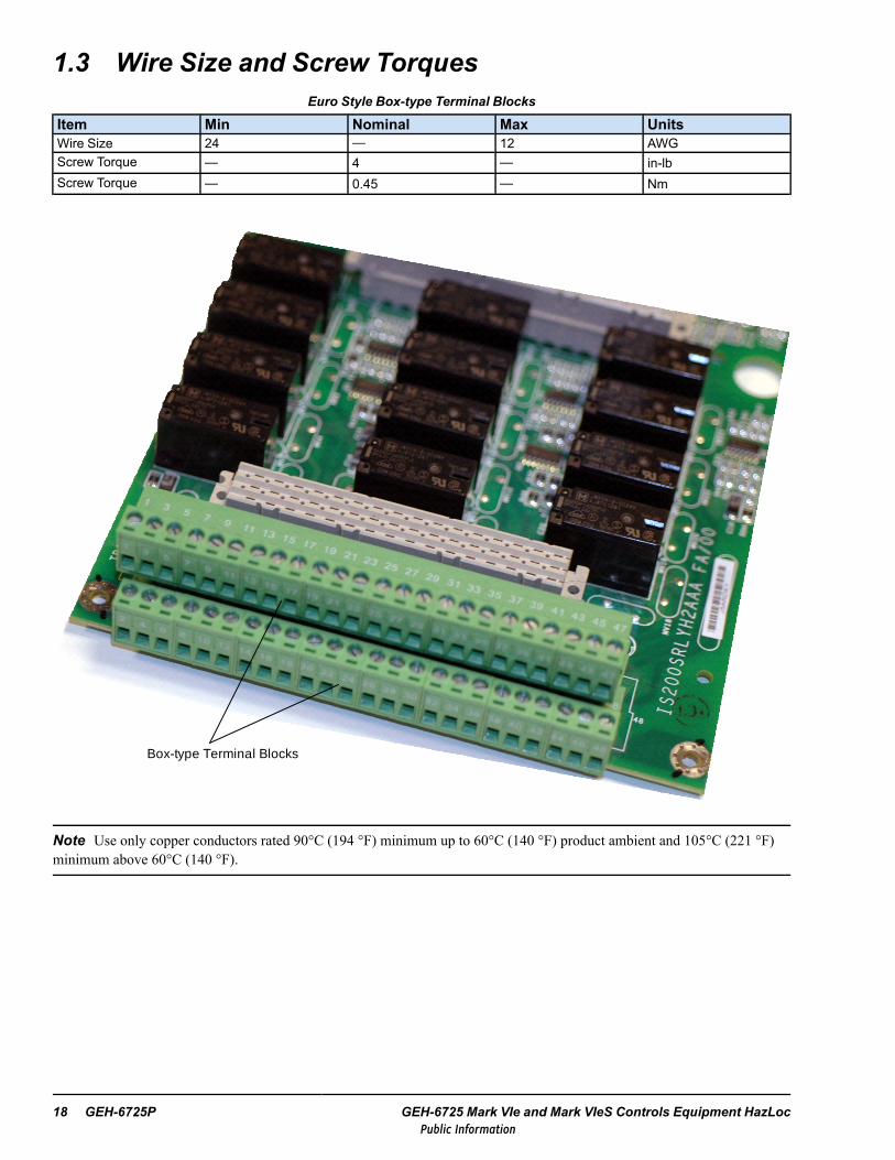
1.3 Wire Size and Screw TorquesEuro Style Box-type Terminal Blocks
Item Min Nominal Max UnitsWire Size 24 — 12 AWGScrew Torque — 4 — in-lbScrew Torque — 0.45 — Nm
Box-type Terminal Blocks
Note Use only copper conductors rated 90°C (194 °F) minimum up to 60°C (140 °F) product ambient and 105°C (221 °F)minimum above 60°C (140 °F).
18 GEH-6725P GEH-6725 Mark VIe and Mark VIeS Controls Equipment HazLocPublic Information

Barrier-type Terminal Blocks
Item Min Nominal Max UnitsWire Size 22 — 12 AWGScrew Torque — 9.6 — in-lbScrew Torque — 1.1 — Nm
Barrier-type Terminal Blocks
Note Use only copper conductors rated 90°C (194 °F) minimum up to 60°C (140 °F) product ambient and 105°C (221 °F)minimum above 60°C (140 °F).
General Instructions GEH-6725P Instruction Guide 19Public Information

1.4 Equipment MarkingsHazardous location certifications vary, depending on the equipment release date and energy limiting characteristics. Thefollowing are actual size examples of HazLoc labels for control system equipment.
IND. CONT. EQ. FOR HAZ. LOC.13EN
E207685
336A4940 LAP51
Power Supply : 28 V dc, 0.78 A dcAnalog In : -10 to +10 V dc , 0 to 20 mA dcThermocouple : -16 to +63 mV dcRTD: 0 to 0.7 V dc, 1 mA dcAnalog Out : 0 to 16.3 V dc, 0 to 20 mA dcAnalog Transmitter Power : 24 V dc , 21 mA dc
IS220PCLAH1BUse with accessories: IS210SCLSH1A, IS200SCLTH1ASee GEH-6725 for instructions / Voir GEH-6725 pour obtenir des instructions
Class I , Div. 2, Groups A ,B,C,D T4Class I , Zone 2, AEx nA nC [nC ] IIC T4, Ex nA nL [nL] IIC T4 Gc XEx ic nA [ic] IIC T4 Gc
GE Drives and Controls , Inc ., 1501 Roanoke Blvd., Salem, Virginia, 24153, USA
-30°C < Ta < 65°C
Listed equipment
Accessories
Instructions
US & CAN Class I Div 2 marking
EU Zone 2 marking
II 3 G DEMKO 13 ATEX 1214780 X
Temperature rating
Electrical rating
Manufacturer’s name and address
US & CAN Class I Zone 2 marking
Label part number
UL Canadian /US MarkingUL Product Identity
UL Control NumberUL File Number
ATEX Marking
ATEX Certificate Number
ART Rev 0 Label artwork revision
Example HazLoc Label on I/O Pack
Example Accessory HazLoc Label
20 GEH-6725P GEH-6725 Mark VIe and Mark VIeS Controls Equipment HazLocPublic Information

2 Controller and Switch InstructionsThe equipment listed in this chapter is certified for use in certain specified hazardous (classified) locations. Follow allapplicable instructions in the section Conditions of Safe Use and the specific section for each piece of equipment for properuse of this equipment in these locations.
2.1 UCSA, UCSB, and UCSC ControllersThe following table lists the controllers that are certified for hazardous location usage.
Note For UCSC controller conditions of safe use and hazardous locations installation requirements, refer to UCSCInstallation and Maintenance Requirements (GFK-3006).
For general application information, refer to theMark VIe and Mark VIeS Control Systems Volume II: General-purposeApplications System Guide (GEH-6721_Vol_II), the section UCSC Controllers.
Processor Part Number NameQuad core, 1.2 GHz AMD© G-Series IS420UCSCH1 Mark VIe controllerDual core, 1.6 GHz AMD G-Series IS420UCSCH2 MarkStat controllerDual core, 1.6 GHz AMD G-Series IS420UCSCS2 Mark VIeS Safety controller
600 MHz EP80579 Intel®
IS420UCSBS1AIS421UCSBS1A (conformal coated)
Mark VIeS Safety controller
IS420UCSBH1AIS421UCSBH1A (conformal coated)
Mark VIe, EX2100e, or LS2100e controller
1066 MHz EP80579 Intel
IS420UCSBH4AIS421UCSBH4A (conformal coated)IS420PPNGH1A PROFINET gateway module
1200 MHz EP80579 Intel IS420UCSBH3A Mark VIe or MarkStat controller
667 MHx PowerQUICC® Pro Freescale IS220UCSAH1A
Mark VIe controllerPAMC Acoustic Monitor (processor)PMVE Migration from Mark V Control (processor)
2.1.1 UCEC ModuleThe IS420UCECH1 module is certified for hazardous location usage. This module is an IS420UCSCH1 controller coupledwith a seven I/O port expansion board. The UCSCH1 controller contained within the UCECH1 module has the same featuresand benefits as the stand-alone UCSCH1 controller. For further details on the UCECH1 module, refer to theMark VIe andMark VIeS Control Systems Volume II: General-purpose Applications System Guide (GEH-6721_Vol_II), the sectionUCECH1x I/O Port Expansion Module.
Controller and Switch Instructions GEH-6725P Instruction Guide 21Public Information

2.1.2 Electrical RatingsPower Supply UCSC Controller
Item Min Nominal Max UnitsVoltage 18.0 24.0/28.0 30.0 V dcCurrent — — 1.1 A dc
Power Supply UCEC Module
Item Min Nominal Max UnitsVoltage 18.0 24.0/28.0 30.0 V dcCurrent — — 1.5 A dc
Power Supply UCSB Controller
Item Min Nominal Max UnitsVoltage 27.4 28.0 28.6 V dcCurrent — — 1.1 A dc
Power Supply UCSA Controller
Item Min Nominal Max UnitsVoltage 27.4 28.0 28.6 V dcCurrent — — 0.62 A dc
22 GEH-6725P GEH-6725 Mark VIe and Mark VIeS Controls Equipment HazLocPublic Information

2.2 ESWx Industrial Ethernet SwitchIndustrial Ethernet Switches Approved for Use in Hazardous Locations
Model # of Copper Ports,10/100 base T
# of Multi-modeFiber-optic Uplinks,
100 base FX
# of Single-modeFiber-optic Uplinks,
100 base FXIS420ESWAH1AIS421ESWAH1A (conformal coated)
8
1 —
IS420ESWAH2AIS421ESWAH2A (conformal coated)
2 —
IS420ESWAH3AIS421ESWAH3A (conformal coated)
— —
IS420ESWAH4A — 1IS420ESWAH5A — 2IS420ESWBH1AIS421ESWBH1A (conformal coated)
16
1 —
IS420ESWBH2AIS421ESWBH2A (conformal coated)
2 —
IS420ESWBH3AIS421ESWBH3A (conformal coated)
— —
IS420ESWBH4A — 1IS420ESWBH5A — 2
2.2.1 Electrical RatingsPower Supply
Item Min Nominal Max UnitsVoltage 22.5 24.0 / 28.0 28.6 V dcCurrent — — 1 A dc
Controller and Switch Instructions GEH-6725P Instruction Guide 23Public Information

Notes
24 GEH-6725P GEH-6725 Mark VIe and Mark VIeS Controls Equipment HazLocPublic Information

3 Distributed I/O Module InstructionsThe equipment listed in this chapter is certified for use in certain specified hazardous (classified) locations. Follow allapplicable instructions in Conditions of Safe Use and within the specific section for each piece of equipment for proper use ofthis equipment in these locations.
3.1 PAIC and YAIC Analog I/O ModulesThe following I/O pack and terminal board combinations are approved for use in hazardous locations:
• Mark VIe Analog I/O pack IS220PAICH1Awith terminal boards (accessories) IS200STAIH1A, IS200STAIH2A, or IS200TBAIH1C
• Mark VIe Analog I/O pack IS220PAICH1Bwith terminal boards (accessories) IS200STAIH1A, IS200STAIH2A, or IS200TBAIH1C
• Mark VIeS Safety Analog I/O pack IS220YAICS1Awith terminal boards (accessories) IS200STAIS1A, IS400STAIS1A, IS200STAIS2A, IS400STAIS2A,IS200TBAIS1C, or IS400TBAIS1C
• Mark VIeS Safety Analog I/O pack ISx2yYAICS1B (where x = 2 or 4 and y = 0 or 1)with terminal boards (accessories) ISx0ySTAIS1A, ISx0ySTAIS2A, or ISx0yTBAIS1C
3.1.1 Electrical RatingsItem Min Nominal Max Units
Power Supply
Voltage PAICH1B / YAICS1B: 22.5PAICH1A / YAICS1A: 27.4
PAICH1B / YAICS1B: 24.0/28.0PAICH1A / YAICS1A: 28.0
28.6 V dc
Current — — 0.49 A dcAnalog Inputs (1-8)
Voltage -10 — 10 V dcCurrent 0 — 20 mA dc
Analog Inputs (9-10)Current -5 — 5 V dcCurrent -1 — 20 mA dc
Analog OutputsVoltage 0 — 16.3 V dcCurrent 0 — 20 mA dc
Analog Transmitter PowerVoltage 22.8 24.0 25.2 V dcCurrent — — 21 mA dc
3.1.2 Field Wire ConnectionsTerminal Board Terminal Block TypeISx00STAI_1A, ISx00STAI_2A Refer to the table Euro Style Box-type Terminal Blocks for wire size and screw torques.ISx00TBAI_1C Refer to the table Barrier-type Terminal Blocks for wire size and screw torques.
Distributed I/O Module Instructions GEH-6725P Instruction Guide 25Public Information

3.1.3 Intrinsic Safety “ic”Wiring Diagram
ASSOCIATED APPARATUSANALOG OUTPUTS
INTRINSICALLY SAFE APPARATUS WITH ENTITY
PARAMETERS:
Vmax => VocImax => Isc
Pi => PoCi + Ccable <= CaLi + Lcable <= La
+
-
Hazardous (Classified) LocationClass I, Division 2, Groups A, B, C, and D
Class I, Zone 2, Group IICATEX Zone 2, Group IIC
Nonhazardous Locationor
Hazardous (Classified) LocationClass I, Division 2, Groups A, B, C, and D
Class I, Zone 2, Group IICATEX Zone 2, Group IIC
Entity Parameters
Analog Outputs Value UnitVoc or Uo 28.6 VIsc or Io 22.4 mAPo 0.64 WCa or Co 0.26 uFLa or Lo 100 mH
Note Analog outputs may be used with non-sparking (nA) devices using appropriate Class I Division 2 or Zone 2 wiringpractices.
Field Terminals
Accessory TB Name (+) Terminal Name (-)Terminal
STAI Signal 1 TB1.45 Return 1 TB1.46
STAI Signal 2 TB1.47 Return 2 TB1.48
TBAI Signal 1 TB2.45 Return 1 TB2.46
TBAI Signal 2 TB2.47 Return 2 TB2.48
26 GEH-6725P GEH-6725 Mark VIe and Mark VIeS Controls Equipment HazLocPublic Information
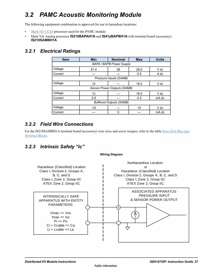
3.2 PAMC Acoustic Monitoring ModuleThe following equipment combination is approved for use in hazardous locations:
• Mark VIe UCSA processor used for the PAMC module• Mark VIe Analog processor IS210BAPAH1A and IS41yBAPBH1Awith terminal board (accessory)
IS210SAMBH1A
3.2.1 Electrical RatingsItem Min Nominal Max Units
BAPA / BAPB Power SupplyVoltage 27.4 28 28.6 V dcCurrent — — 0.5 A dc
Pressure Inputs (SAMB)Voltage 12 — 18.5 V dc
Sensor Power Outputs (SAMB)Voltage 12 — 18.5 V dcCurrent 2.9 — 4.3 mA dc
Buffered Outputs (SAMB)Voltage -10 — 10 V dcCurrent — 5 — mA dc
3.2.2 Field Wire ConnectionsFor the IS210SAMBH1A terminal board (accessory) wire sizes and screw torques, refer to the table Euro Style Box-typeTerminal Blocks.
3.2.3 Intrinsic Safety “ic”Wiring Diagram
ASSOCIATED APPARATUSPRESSURE INPUT
& SENSOR POWER OUTPUTINTRINSICALLY SAFE
APPARATUS WITH ENTITY PARAMETERS:
Vmax => VocImax => Isc
Pi => PoCi + Ccable <= CaLi + Lcable <= La
+
-
Nonhazardous Locationor
Hazardous (Classified) LocationClass I, Division 2, Groups A, B, C, and D
Class I, Zone 2, Group IICATEX Zone 2, Group IIC
Hazardous (Classified) LocationClass I, Division 2, Groups A,
B, C, and DClass I, Zone 2, Group IICATEX Zone 2, Group IIC
Distributed I/O Module Instructions GEH-6725P Instruction Guide 27Public Information

Note 1. BAPA pressure inputs and sensor power outputs may be used with non-sparking (nA) devices using appropriateClass I Division 2 or Zone 2 wiring practices.
Note 2. Set jumpers JP1 – JP18 on SAMB accessory terminal board to the PCB position.
Note 3. he Analog Processor, IS410BAPBH1A (comprised of IS400BAPBH1A and IS400BBAAH2A), and theIS210SAMBH1A terminal board should only be powered by the ISxxxJPDHG1A distribution board, which is a limitedvoltage limited current (LVLC) circuit, or similar.
Entity Parameters
Pressure Inputs Value Unit Sensor Power Outputs Value UnitVmax 25 V Voc or Uo 25 VImax 4.3 mA Isc or Io 4.3 mAPi 108 mW Po 108 mWCi 0.011 uF Ca or Co 0.4 uFLi 0 mH La or Lo 100 mH
Field Terminals
Name (+) Terminal Name (-) Terminal
SIG1 TB1A.2 RET1 TB1A.4
SIG2 TB1A.6 RET2 TB1A.8
SIG3 TB1A.10 RET3 TB1A.12
SIG4 TB1A.14 RET4 TB1A.16
SIG5 TB1A.18 RET5 TB1A.20
SIG6 TB1A.22 RET6 TB1A.24
SIG7 TB1B.26 RET7 TB1B.28
SIG8 TB1B.30 RET8 TB1B.32
SIG9 TB1B.34 RET9 TB1B.36
SIG10 TB1B.38 RET10 TB1B.40
SIG11 TB1B.42 RET11 TB1B.44
SIG12 TB1B.46 RET12 TB1B.48
SIG13 TB1C.50 RET13 TB1C.52
SIG14 TB1C.54 RET14 TB1C.56
SIG15 TB1C.58 RET15 TB1C.60
SIG16 TB1C.62 RET16 TB1C.64
SIG17 TB1C.66 RET17 TB1C.68
SIG18 TB1C.70 RET18 TB1C.72
28 GEH-6725P GEH-6725 Mark VIe and Mark VIeS Controls Equipment HazLocPublic Information

3.3 PAOC Analog Output ModuleThe following I/O pack and terminal board combinations are approved for use in hazardous locations:
• Analog output pack IS220PAOCH1Bwith terminal boards (accessories) IS200STAOH1A, IS200STAOH2A, or IS200TBAOH1C
3.3.1 Electrical RatingsItem Min Nominal Max Units
Power SupplyVoltage 27.4 28 28.6 V dcCurrent — — 0.45 A dc
Analog OutputsVoltage 0 — 18 V dcCurrent 0 — 20 mA dc
3.3.2 Field Wire ConnectionsTerminal Board Terminal Block Type
IS200STAOH1A, IS200STAOH2ARefer to the table Euro Style Box-type Terminal Blocks for wire size and screwtorques.
IS200TBAOH1C Refer to the table Barrier-type Terminal Blocks for wire size and screw torques.
3.3.3 Intrinsic Safety “ic”Wiring Diagram
ASSOCIATED APPARATUSANALOG OUTPUTS
INTRINSICALLY SAFE APPARATUS WITH ENTITY
PARAMETERS:
Vmax => VocImax => Isc
Pi => PoCi + Ccable <= CaLi + Lcable <= La
+
-
Hazardous (Classified) LocationClass I, Division 2, Groups A, B, C, and D
Class I, Zone 2, Group IICATEX Zone 2, Group IIC
Nonhazardous Locationor
Hazardous (Classified) LocationClass I, Division 2, Groups A, B, C, and D
Class I, Zone 2, Group IICATEX Zone 2, Group IIC
Entity Parameters
Analog Outputs Value UnitVoc or Uo 28.6 VIsc or Io 22.5 mAPo 0.64 WCa or Co 0.26 uFLa or Lo 100 mH
Distributed I/O Module Instructions GEH-6725P Instruction Guide 29Public Information

Note Analog outputs may be used with non-sparking (nA) devices using appropriate Class I Division 2 or Zone 2 wiringpractices.
Field TerminalsAccessory TB Name (+) Terminal Name (-) TerminalSTAO Signal 1 TB1.1 Return 1 TB1.2STAO Signal 2 TB1.3 Return 2 TB1.4STAO Signal 3 TB1.5 Return 3 TB1.6STAO Signal 4 TB1.7 Return 4 TB1.8STAO Signal 5 TB1.9 Return 5 TB1.10STAO Signal 6 TB1.11 Return 6 TB1.12STAO Signal 7 TB1.13 Return 7 TB1.14STAO Signal 8 TB1.15 Return 8 TB1.16TBAO Signal 1 TB1.1 Return 1 TB1.2TBAO Signal 2 TB1.3 Return 2 TB1.4TBAO Signal 3 TB1.5 Return 3 TB1.6TBAO Signal 4 TB1.7 Return 4 TB1.8TBAO Signal 5 TB1.9 Return 5 TB1.10TBAO Signal 6 TB1.11 Return 6 TB1.12TBAO Signal 7 TB1.13 Return 7 TB1.14TBAO Signal 8 TB1.15 Return 8 TB1.16TBAO Signal 9 TB1.17 Return 9 TB1.18TBAO Signal 10 TB1.19 Return 10 TB1.20TBAO Signal 11 TB1.21 Return 11 TB1.22TBAO Signal 12 TB1.23 Return 12 TB1.24TBAO Signal 13 TB2.25 Return 13 TB2.26TBAO Signal 14 TB2.27 Return 14 TB2.28TBAO Signal 15 TB2.29 Return 15 TB2.30TBAO Signal 16 TB2.31 Return 16 TB2.32
30 GEH-6725P GEH-6725 Mark VIe and Mark VIeS Controls Equipment HazLocPublic Information

3.4 PCLA Core Analog Module — AeroThe following hardware combinations are approved for use in hazardous locations:
• Core analog module IS220PCLAH1A or IS220PCLAH1B• Terminal board (accessory) IS210SCLSH1A• Optional terminal board (accessory) IS200SCLTH1A
3.4.1 Electrical RatingsItem Min Nominal Max Units
Power SupplyVoltage 27.4 28 28.6 V dcCurrent — — 0.78 A dc
Analog InputsVoltage -10 — 10 V dcCurrent 0 — 20 mA dc
Thermocouple InputsVoltage -16 — 63 mV dc
RTD InputsVoltage 0 — 0.7 V dcCurrent — 1.0 — mA dc
Analog OutputsVoltage 0 — 16.3 V dcCurrent 0 — 20 mA dc
Analog Transmitter PowerVoltage 22.8 24.0 25.2 V dcCurrent — — 21 mA dc
3.4.2 Field Wire ConnectionsFor the core analog terminal boards (accessories) wire sizes and screw torques, refer to the table Euro Style Box-type TerminalBlocks.
Distributed I/O Module Instructions GEH-6725P Instruction Guide 31Public Information

3.4.3 Intrinsic Safety “ic” for Thermocouple InputsWiring Diagram
ASSOCIATED APPARATUSTHERMOCOUPLE INPUTS
INTRINSICALLY SAFE APPARATUS WITH ENTITY
PARAMETERS:
Vmax => VocImax => Isc
Pi => PoCi + Ccable <= CaLi + Lcable <= La
ORSIMPLE APPARATUS
-BIAS
+BIAS
-
+
Hazardous (Classified) LocationClass I, Division 2, Groups A, B, C, and D
Class I, Zone 2, Group IICATEX Zone 2, Group IIC
Nonhazardous Locationor
Hazardous (Classified) LocationClass I, Division 2, Groups A, B, C, and D
Class I, Zone 2, Group IICATEX Zone 2, Group IIC
+
-
Entity Parameters
Thermocouple Inputs Value UnitVoc or Uo 0.5 VIsc or Io 25 nAPo 13 nWCa or Co 1000 uFLa or Lo 100 mH
Note 1. This associated apparatus may also be connected to simple apparatus as defined in Article 504.2 and installed andtemperature classified in accordance with Article 504.10(B) of the National Electrical Code (ANSI/NFPA 70), or other localcodes, as applicable.
Note 2. Only resistive simple apparatus (such as thermocouples) shall be connected to thermocouple inputs
Note 3. Each cable used to connect the simple apparatus must have suitable insulation as required by the applicable localelectrical codes.
Note 4. The maximum cable length connecting each thermocouple to the device shall not exceed 1000 ft.
32 GEH-6725P GEH-6725 Mark VIe and Mark VIeS Controls Equipment HazLocPublic Information

Field TerminalsAccessory TB Name (-) Terminal Name (+)Terminal
SCLS
TC1H TB1B.25 TC1L TB1B.26TC2H TB1B.27 TC2L TB1B.28TC3H TB1B.29 TC3L TB1B.30TC4H TB1B.31 TC4L TB1B.32TC5H TB1B.33 TC5L TB1B.34TC6H TB1B.35 TC6L TB1B.36TC7H TB1B.37 TC7L TB1B.38TC8H TB1B.39 TC8L TB1B.40
SCLT
TC9H TB1.1 TC9L TB1.2TC10H TB1.3 TC10L TB1.4TC11H TB1.5 TC11L TB1.6TC12H TB1.7 TC12L TB1.8TC13H TB1.9 TC13L TB1.10TC14H TB1.11 TC14L TB1.12TC15H TB1.13 TC15L TB1.14TC16H TB1.15 TC16L TB1.16
3.4.4 Intrinsic Safety “ic” for RTD InputsWiring Diagram
ASSOCIATED APPARATUSRTD INPUTS
Hazardous (Classified) LocationClass I, Division 2, Groups A, B, C, and D
Class I, Zone 2, Group IICATEX Zone 2, Group IIC
INTRINSICALLY SAFE APPARATUS WITH ENTITY
PARAMETERS:
Vmax => VocImax => Isc
Pi => PoCi + Ccable <= CaLi + Lcable <= La
ORSIMPLE APPARATUS
+
-
S
Nonhazardous Locationor
Hazardous (Classified) LocationClass I, Division 2, Groups A, B, C, and D
Class I, Zone 2, Group IICATEX Zone 2, Group IIC
Entity Parameters
RTD Inputs Value Unit
Voc or Uo 15 V
Isc or Io 1.0 mA
Po 15 mW
Ca or Co 3 uF
La or Lo 100 mH
Distributed I/O Module Instructions GEH-6725P Instruction Guide 33Public Information

Note 1. This associated apparatus may also be connected to simple apparatus as defined in Article 504.2 and installed andtemperature classified in accordance with Article 504.10(B) of the National Electrical Code (ANSI/NFPA 70), or other localcodes, as applicable.
Note 2. Only resistive simple apparatus (such as RTDs) shall be connected to RTD inputs.
Note 3. Each cable used to connect the simple apparatus must have suitable insulation as required by the applicable localelectrical codes.
Note 4. The maximum cable length connecting each RTD to the device shall not exceed 1000 ft.
Field TerminalsAccessory TB Name (+) Terminal Name (S) Terminal Name (-)Terminal
SCLS
RTDEXC1 TB1C.49 RTDSIG1 TB1C.50 RTDRET1 TB1C.51RTDEXC2 TB1C.52 RTDSIG2 TB1C.53 RTDRET2 TB1C.54RTDEXC3 TB1C.55 RTDSIG3 TB1C.56 RTDRET3 TB1C.57RTDEXC4 TB1C.58 RTDSIG4 TB1C.59 RTDRET4 TB1C.60RTDEXC5 TB1C.61 RTDSIG5 TB1C.62 RTDRET5 TB1C.63RTDEXC6 TB1C.64 RTDSIG6 TB1C.65 RTDRET6 TB1C.66RTDEXC7 TB1C.67 RTDSIG7 TB1C.68 RTDRET7 TB1C.69RTDEXC8 TB1C.70 RTDSIG8 TB1C.71 RTDRET8 TB1C.72
34 GEH-6725P GEH-6725 Mark VIe and Mark VIeS Controls Equipment HazLocPublic Information

3.4.5 Intrinsic Safety “ic” for Analog OutputsWiring Diagram
ASSOCIATED APPARATUSANALOG OUTPUTS
INTRINSICALLY SAFE APPARATUS WITH ENTITY
PARAMETERS:
Vmax => VocImax => Isc
Pi => PoCi + Ccable <= CaLi + Lcable <= La
+
-
Hazardous (Classified) LocationClass I, Division 2, Groups A, B, C, and D
Class I, Zone 2, Group IICATEX Zone 2, Group IIC
Nonhazardous Locationor
Hazardous (Classified) LocationClass I, Division 2, Groups A, B, C, and D
Class I, Zone 2, Group IICATEX Zone 2, Group IIC
Entity Parameters
Analog Outputs Value UnitVoc or Uo 28.6 VIsc or Io 22.4 mAPo 0.64 WCa or Co 0.26 uFLa or Lo 100 mH
Note Analog outputs may be used with non-sparking (nA) devices using appropriate Class I Division 2 or Zone 2 wiringpractices.
Field TerminalsAccessory TB Name (+) Terminal Name (-)TerminalSCLS OP1 TB1A.21 OR1 TB1A.22
SCLT
OP2 TB1.37 OR2 TB1.38OP3 TB1.39 OR3 TB1.40OP4 TB1.41 OR4 TB1.42OP5 TB1.43 OR5 TB1.44OP6 TB1.45 OR6 TB1.46OP7 TB1.47 OR7 TB1.48
Distributed I/O Module Instructions GEH-6725P Instruction Guide 35Public Information

3.5 PCNO CANopen® Master Gateway ModuleThe following I/O pack and terminal board combinations are approved for use in hazardous locations:
• CANopen I/O pack IS220PCNOH1A or IS220PCNOH1B with accessory ID board IS200SPIDG1A
3.5.1 Electrical RatingsPower Supply
Item Min Nominal Max UnitsVoltage 27.4 28.0 28.6 V dc
Current — — 0.17 A dc
3.6 PDIA and YDIA Discrete Input ModulesThe following I/O pack and terminal board combinations are approved for use in hazardous locations:
• Mark VIe Discrete I/O pack IS220PDIAH1Awith terminal boards (accessories) IS200STCIH1A, IS200STCIH2A, IS200STCIH8A, IS200TBCIH2C, orIS200TBCIH4C
• Mark VIe Discrete I/O pack IS220PDIAH1Bwith terminal boards (accessories) IS200STCIH1A, IS200STCIH2A, IS200STCIH8A, IS200TBCIH2C,IS400TBCIH2C, IS200TBCIH4C, IS400STCIH1A, IS400STCIH2A, or IS400STCIH8A
• Coated Mark VIe Discrete I/O pack IS221PDIAH1Bwith coated terminal boards (accessories) IS201STCIH1A, IS201STCIH2A, IS201STCIH8A, IS201TBCIH2C, orIS201TBCIH4C
• Mark VIeS Safety Discrete I/O pack IS220YDIAS1Awith terminal boards (accessories) IS200STCIS1A, IS200STCIS2A, IS400STCIS1A, IS400STCIS2A,IS200TBCIS2C, or IS400TBCIS2C
• Mark VIeS Safety Discrete I/O pack ISx2yYDIAS1B (where x = 2 or 4 and y = 0 or 1)with terminal boards (accessories) ISx0ySTCIS1A, ISx0ySTCIS2A, IS40ySTCIS4A, ISx0yTBCIS2C, orIS40yTBCIS3C
36 GEH-6725P GEH-6725 Mark VIe and Mark VIeS Controls Equipment HazLocPublic Information

3.6.1 Electrical RatingsPDIAH1A and PDIAH1B
Item Min Nominal Max UnitsPower Supply
Voltage PDIAH1B: 22.5PDIAH1A: 27.4
PDIAH1B: 24.0/28.0PDIAH1A: 28.0
28.6 V dc
Current — — 0.24 A dcContact Inputs
Voltage 0 — 32 V dcSTCIH1A, STCIH2A, TBCIH2C Contact Wetting Outputs
Voltage 18.5 — 32 V dcCurrent — — 110 mA dc
STCIH8A, TBCIH4C Contact Wetting Outputs (1-21)Voltage — — 31 V dcCurrent — — 10 mA dc
STCIH8A, TBCIH4C Contact Wetting Outputs (22-24)Voltage — — 31 V dcCurrent — — 41 mA dc
YDIAS1AItem Min Nominal Max Units
Power SupplyVoltage 27.4 28.0 28.6 V dcCurrent — — 0.24 A dc
Contact InputsVoltage 0 — 32 V dc
Contact Wetting OutputsVoltage PDIA — 32 V dcCurrent — — 110 mA dc
YDIAS1BItem Min Nominal Max Units
Power SupplyVoltage 22.5 28.0 28.6 V dcCurrent — — 0.24 A dc
Contact Inputs/Wetting (via JE1) STCIS1, STCIS2, TBCIS2Voltage 20 24 32 V dcCurrent — — 110 mA dc
Contact Inputs/Wetting (via JE1) STCIS4, TBCIS3Voltage 43 48 52.8 V dcCurrent — — 110 mA dc
3.6.2 Field Wire ConnectionsTerminal Board Terminal Block TypeSTCI Refer to the table Euro Style Box-type Terminal Blocks for wire size and screw torques.
TBCI Refer to the table Barrier-type Terminal Blocks for wire size and screw torques.
Distributed I/O Module Instructions GEH-6725P Instruction Guide 37Public Information
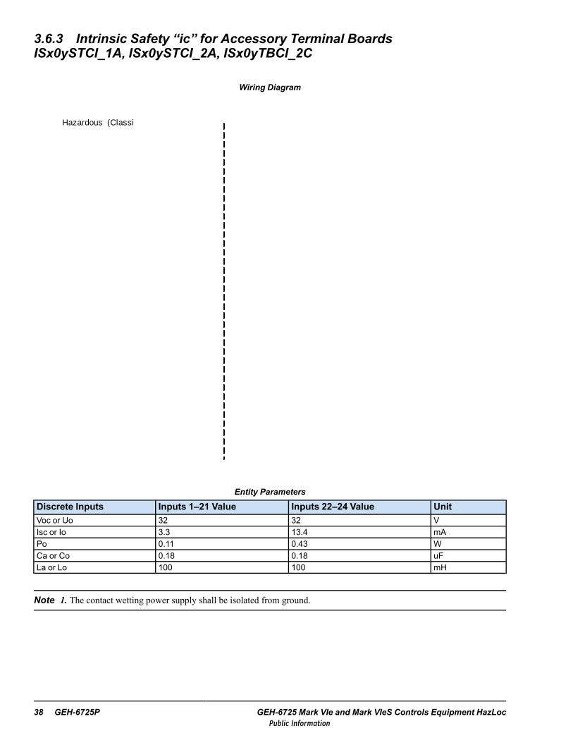
3.6.3 Intrinsic Safety “ic” for Accessory Terminal BoardsISx0ySTCI_1A, ISx0ySTCI_2A, ISx0yTBCI_2C
Wiring Diagram
Hazardous (Classi ed ) LocationClass I, Division 2, Groups A , B, C, and D
Class I , Zone 2, Group IICATEX Zone 2, Group IIC
Nonhazardous Locationor
Hazardous (Classi ed) LocationClass I, Division 2, Groups A , B, C, and D
Class I, Zone 2, Group IICATEX Zone 2, Group IIC
DISCRETE INPUTS
Contact Wetting Power Supply
DISCRETE INPUTS
Contact Wetting Power Supply
ISx00STCI_1A or ISx00STCI_2A
ISx00TBCI_2C
Entity Parameters
Discrete Inputs Inputs 1–21 Value Inputs 22–24 Value UnitVoc or Uo 32 32 VIsc or Io 3.3 13.4 mAPo 0.11 0.43 WCa or Co 0.18 0.18 uFLa or Lo 100 100 mH
Note 1. The contact wetting power supply shall be isolated from ground.
38 GEH-6725P GEH-6725 Mark VIe and Mark VIeS Controls Equipment HazLocPublic Information

Note 2. For North American locations, if contact wetting power is supplied to the accessory terminal board throughconnector JE1 or JE2, the wire harness specified on drawing 336A4937FJ shall be used, and the wetting power source shallbe current limited by either a UL recognized fuse rated at not more than 3 A, or one of the following power supplies:
• UL R/C, Phoenix Contact GmbH & Co Kg, model QUINT-PS-100-240AC/24DC/5 GE
• UL R/C, Convertec Ltd., model TIS 150-124
Note 3. The output current of this associated apparatus is limited by a resistor such that the output voltage-current plot is astraight line drawn between open-circuit voltage and short-circuit current.
Note 4. This associated apparatus may also be connected to simple apparatus as defined in Article 504.2 and installed andtemperature classified in accordance with Article 504.10(B) of the National Electrical Code (ANSI/NFPA 70), or other localcodes, as applicable.
Note 5. Only resistive simple apparatus (such as relay contacts or switches) shall be connected to discrete inputs.
Note 6. Each cable used to connect the simple apparatus must have suitable insulation as required by the applicable localelectrical codes.
Distributed I/O Module Instructions GEH-6725P Instruction Guide 39Public Information

3.6.4 Intrinsic Safety “ic” for Accessory Terminal BoardsISx00STCI_8A, IS200TBCI_4C
Wiring Diagram
Hazardous (Classi ed ) LocationClass I, Division 2, Groups A , B, C, and D
Class I , Zone 2, Group IICATEX Zone 2, Group IIC
Nonhazardous Locationor
Hazardous (Classi ed ) LocationClass I , Division 2, Groups A , B, C, and D
Class I, Zone 2, Group IICATEX Zone 2, Group IIC
DISCRETE INPUTS
DISCRETE INPUTS
Contact Wetting Power Supply
Contact Wetting Power Supply
ISx00STCI_8A
ISx00TBCI_4C
40 GEH-6725P GEH-6725 Mark VIe and Mark VIeS Controls Equipment HazLocPublic Information

Entity Parameters
Discrete Inputs Inputs 1–21 Value Inputs 22–24 Value Unit
Voc or Uo 31 31 V
Isc or Io 3.2 13 mA
Po 0.10 0.40 W
Ca or Co 0.18 0.18 uF
La or Lo 100 100 mH
Note 1. The contact wetting power supply may be grounded.
Note 2. For North American locations, if contact wetting power is supplied to the accessory terminal board throughconnector JE1 or JE2, the wire harness specified on drawing 336A4937FJ shall be used, and the wetting power source shallbe current limited by either a UL recognized fuse rated at not more than 3 A, or one of the following power supplies:
• UL R/C, Phoenix Contact GmbH & Co Kg, model QUINT-PS-100-240AC/24DC/5 GE
• UL R/C, Convertec Ltd., model TIS 150-124
Note 3. The output current of this associated apparatus is limited by a resistor such that the output voltage-current plot is astraight line drawn between open-circuit voltage and short-circuit current.
Note 4. This associated apparatus may also be connected to simple apparatus as defined in Article 504.2 and installed andtemperature classified in accordance with Article 504.10(B) of the National Electrical Code (ANSI/NFPA 70), or other localcodes, as applicable.
Note 5. Only resistive simple apparatus (such as relay contacts or switches) shall be connected to discrete inputs.
Note 6. Each cable used to connect the simple apparatus must have suitable insulation as required by the applicable localelectrical codes.
Distributed I/O Module Instructions GEH-6725P Instruction Guide 41Public Information

Field TerminalsAccessory TB Name (+) Terminal Input (-)Terminal
STCI or TBCI
Contact Wetting 1 TB1.1 1 TB1.2Contact Wetting 2 TB1.3 2 TB1.4Contact Wetting 3 TB1.5 3 TB1.6Contact Wetting 4 TB1.7 4 TB1.8Contact Wetting 5 TB1.9 5 TB1.10Contact Wetting 6 TB1.11 6 TB1.12Contact Wetting 7 TB1.13 7 TB1.14Contact Wetting 8 TB1.15 8 TB1.16Contact Wetting 9 TB1.17 9 TB1.18Contact Wetting 10 TB1.19 10 TB1.20Contact Wetting 11 TB1.21 11 TB1.22Contact Wetting 12 TB1.23 12 TB1.24
STCI
Contact Wetting 13 TB1.25 13 TB1.26Contact Wetting 14 TB1.27 14 TB1.28Contact Wetting 15 TB1.29 15 TB1.30Contact Wetting 16 TB1.31 16 TB1.32Contact Wetting 17 TB1.33 17 TB1.34Contact Wetting 18 TB1.35 18 TB1.36Contact Wetting 19 TB1.37 19 TB1.38Contact Wetting 20 TB1.39 20 TB1.40Contact Wetting 21 TB1.41 21 TB1.42Contact Wetting 22 TB1.43 22 TB1.44Contact Wetting 23 TB1.45 23 TB1.46Contact Wetting 24 TB1.47 24 TB1.48
TBCI
Contact Wetting 13 TB2.25 13 TB2.26Contact Wetting 14 TB2.27 14 TB2.28Contact Wetting 15 TB2.29 15 TB2.30Contact Wetting 16 TB2.31 16 TB2.32Contact Wetting 17 TB2.33 17 TB2.34Contact Wetting 18 TB2.35 18 TB2.36Contact Wetting 19 TB2.37 19 TB2.38Contact Wetting 20 TB2.39 20 TB2.40Contact Wetting 21 TB2.41 21 TB2.42Contact Wetting 22 TB2.43 22 TB2.44Contact Wetting 23 TB2.45 23 TB2.46Contact Wetting 24 TB2.47 24 TB2.48
42 GEH-6725P GEH-6725 Mark VIe and Mark VIeS Controls Equipment HazLocPublic Information

3.7 PDII Isolated Discrete Input ModuleThe following I/O pack and terminal board combinations are approved for use in hazardous locations:
• Discrete I/O pack IS220PDIIH1B with terminal board (accessory) IS200SDIIH1A
3.7.1 Electrical RatingsItem Min Nominal Max Units
Power SupplyVoltage 27.4 28.0 28.6 V dcCurrent — — 0.15 A dc
Contact inputsVoltage 0 — 32 V dc
3.7.2 Field Wire ConnectionsFor IS200SDIIH1A terminal board (accessory) wire sizes and screw torques, refer to the table Euro Style Box-type TerminalBlocks.
Distributed I/O Module Instructions GEH-6725P Instruction Guide 43Public Information

3.8 PDIO Discrete Input/Output ModuleThe following I/O pack and terminal board combinations are approved for use in hazardous locations:
• Discrete I/O pack IS220PDIOH1Awith terminal boards (accessories) IS200TDBSH2A or IS200TDBTH2A
• Discrete I/O pack IS220PDIOH1Bwith terminal boards (accessories) IS200TDBSH2A, IS200TDBSH8A, IS200TDBTH2A, or IS200TDBTH8A
3.8.1 Electrical RatingsPDIOH1A
Item Min Nominal Max UnitsPower Supply
Voltage 27.4 28.0 28.6 V dcCurrent — — 0.81 A dc
Contact InputsVoltage 0 — 32 V dc
Contact OutputsVoltage — — 32.0 V dcCurrent — — 3.15 A dc
Contact Wetting OutputsVoltage — — 32 V dcCurrent — — 110 mA dc
PDIOH1BItem Min Nominal Max Units
Power SupplyVoltage 27.4 28.0 28.6 V dcCurrent — — 0.81 A dc
Contact InputsVoltage 0 — 32 V dc
TDBSH2A, TDBTH2A Contact Wetting OutputsVoltage 16 — 32 V dcCurrent — — 110 mA dc
TDBSH8A, TDBTH8A Contact Wetting Outputs (1-21)Voltage — — 31 V dcCurrent — — 10 mA dc
TDBSH8A, TDBTH8A Contact Wetting Outputs (22-24)Voltage — — 31 V dcCurrent — — 41 mA dc
Contact OutputsVoltage — — 32.0 V dcCurrent — — 3.15 A dc
44 GEH-6725P GEH-6725 Mark VIe and Mark VIeS Controls Equipment HazLocPublic Information

3.8.2 Field Wire ConnectionsFor discrete input/output terminal boards (accessories) certified for HazLoc, refer to the table Euro Style Box-type TerminalBlocks for wire size and screw torques.
3.8.3 Intrinsic Safety “ic” for Relay Contacts — Accessory Terminal BoardsIS200TDBS and IS200TDBT
Nonhazardous Locationor
Hazardous (Classified) LocationClass I, Division 2, Groups A, B, C, and D
Class I, Zone 2, Group IICATEX Zone 2, Group IIC
Nonhazardous Locationor
Hazardous (Classified) LocationClass I, Division 2, Groups A, B, C, and D
Class I, Zone 2, Group IICATEX Zone 2, Group IIC
ASSOCIATED APPARATUS WITH ENTITY
PARAMETERS:
Vmax => VocImax => Isc
Pi => PoCi + Ccable <= CaLi + Lcable <= La
INTRINSICALLY SAFE APPARATUS
RELAY CONTACTS
ASSOCIATED APPARATUS WITH ENTITY
PARAMETERS:
Vmax => VocImax => Isc
Pi => PoCi + Ccable <= CaLi + Lcable <= La
INTRINSICALLY SAFE APPARATUS
RELAY CONTACTS
Wiring Diagram
IS200TDBS or IS200TDBT
IS200TDBS or IS200TDBT
Entity Parameters
Relay Contacts Value UnitVmax or Ui 32 VImax or Ii 132 mAPi 4.22 WCi 0 uFLi 0 mH
Distributed I/O Module Instructions GEH-6725P Instruction Guide 45Public Information

Field Terminals for Relay Contacts
Accessory TB Name Terminal Output Terminal
TDBS or TDBT
NC1 TB1.1 COM1 TB1.2NO1 TB1.3 Not used TB1.4NC2 TB1.5 COM2 TB1.6NO2 TB1.7 Not used TB1.8NC3 TB1.9 COM3 TB1.10NO3 TB1.11 Not used TB1.12NC4 TB1.13 COM4 TB1.14NO4 TB1.15 Not used TB1.16NC5 TB1.17 COM5 TB1.18NO5 TB1.19 Not used TB1.20NC6 TB1.21 COM6 TB1.22NO6 TB1.23 Not used TB1.24NC7 TB1.25 COM7 TB1.26NO7 TB1.27 Not used TB1.28NC8 TB1.29 COM8 TB1.30NO8 TB1.31 Not used TB1.32NC9 TB1.33 COM8 TB1.34NO9 TB1.35 Not used TB1.36NC10 TB1.37 COM10 TB1.38NO10 TB1.39 Not used TB1.40NC11 TB1.41 COM11 TB1.42NO11 TB1.43 Not used TB1.44NC12 TB1.45 COM12 TB1.46NO12 TB1.47 Not used TB1.48
46 GEH-6725P GEH-6725 Mark VIe and Mark VIeS Controls Equipment HazLocPublic Information

3.8.4 Intrinsic Safety “ic” for Discrete Inputs — Accessory Terminal BoardsIS200TDBS_2A, IS200TDBT_2A
Hazardous (Classified) LocationClass I, Division 2, Groups A, B, C, and D
Class I, Zone 2, Group IIC
Wiring Diagram
Nonhazardous Locationor
Hazardous (Classified) LocationClass I, Division 2, Groups A, B, C, and D
Class I, Zone 2, Group IIC
ASSOCIATED APPARATUSDISCRETE INPUTSINTRINSICALLY SAFE
APPARATUS WITH ENTITY PARAMETERS:
Vmax => VocImax => Isc
Pi => PoCi + Ccable <= CaLi + Lcable <= La
ORSIMPLE APPARATUS
+
-
Input Isolator Contact Wetting Power Supply
JE1.1
JE1.3
+-
IS200TDBS_2A or IS200TDBT_2A
Entity Parameters
Inputs 1 – 21 Inputs 22 - 24
DiscreteInputs Value Unit
DiscreteInputs Value Unit
Voc or Uo 32 V Voc or Uo 32 V
Isc or Io 3.3 mA Isc or Io 13.4 mA
Po 0.11 W Po 0.43 W
Ca or Co 0.18 uF Ca or Co 0.18 uF
La or Lo 100 mH La or Lo 100 mH
Note 1. The contact wetting power supply used with IS200TDBS_2A or IS200TDBT_ 2A shall be isolated from ground.
Note 2. For North American locations, if contact wetting power is supplied to the accessory terminal board throughconnector JE1, the wire harness specified on drawing 336A4937FJ shall be used, and the wetting power source shall becurrent limited by either a UL recognized fuse rated at not more than 3 A, or one of the following power supplies:
• UL R/C, Phoenix Contact GmbH & Co Kg, model QUINT-PS-100-240AC/24DC/5 GE
• UL R/C, Convertec Ltd., model TIS 150-124
Note 3. The output current of this associated apparatus is limited by a resistor such that the output voltage-current plot is astraight line drawn between open-circuit voltage and short-circuit current.
Distributed I/O Module Instructions GEH-6725P Instruction Guide 47Public Information

Note 4. This associated apparatus may also be connected to simple apparatus as defined in Article 504.2 and installed andtemperature classified in accordance with Article 504.10(B) of the National Electrical Code (ANSI/NFPA 70), or other localcodes, as applicable.
Note 5. Only resistive simple apparatus (such as relay contacts or switches) shall be connected to discrete inputs.
Note 6. Each cable used to connect the simple apparatus must have suitable insulation as required by the applicable localelectrical codes.
48 GEH-6725P GEH-6725 Mark VIe and Mark VIeS Controls Equipment HazLocPublic Information

3.8.5 Intrinsic Safety “ic” for Discrete Inputs — Accessory Terminal BoardsIS200TDBS_8A, IS200TDBT_8A
Wiring Diagram
Hazardous (Classified) LocationClass I, Division 2, Groups A, B, C, and D
Class I, Zone 2, Group IICATEX Zone 2, Group IIC
Nonhazardous Locationor
Hazardous (Classified) LocationClass I, Division 2, Groups A, B, C, and D
Class I, Zone 2, Group IICATEX Zone 2, Group IIC
ASSOCIATED APPARATUSDISCRETE INPUTS
INTRINSICALLY SAFE APPARATUS WITH ENTITY
PARAMETERS:
Vmax => VocImax => Isc
Pi => PoCi + Ccable <= CaLi + Lcable <= La
ORSIMPLE APPARATUS
+
-
Input IsolatorContact Wetting Power Supply
JE1.1
JE1.3
+-
IS200TDBS_8A or IS200TDBT_8A
Entity Parameters
Discrete Inputs Inputs 1–21 Value Inputs 22–24 Value UnitVoc or Uo 31 31 VIsc or Io 3.2 13 mAPo 0.10 0.40 WCa or Co 0.18 0.18 uFLa or Lo 100 100 mH
Note 1. The contact wetting power supply used with IS200TDBS_8A or IS200TDBT_8A may be grounded.
Note 2. For North American locations, if contact wetting power is supplied to the accessory terminal board throughConnector JE1, the wire harness specified on drawing 336A4937FJ shall be used, and the wetting power source shall becurrent limited by either a UL recognized fuse rated at not more than 3 A, or one of the following power supplies:
• UL R/C, Phoenix Contact GmbH & Co Kg, model QUINT-PS-100-240AC/24DC/5 GE
• UL R/C, Convertec Ltd., model TIS 150-124
Note 3. The output current of this associated apparatus is limited by a resistor such that the output voltage-current plot is astraight line drawn between open-circuit voltage and short-circuit current.
Note 4. This associated apparatus may also be connected to simple apparatus as defined in Article 504.2 and installed andtemperature classified in accordance with Article 504.10(B) of the National Electrical Code (ANSI/NFPA 70), or other localcodes, as applicable.
Distributed I/O Module Instructions GEH-6725P Instruction Guide 49Public Information

Note 5. Only resistive simple apparatus (such as relay contacts or switches) shall be connected to discrete inputs.
Note 6. Each cable used to connect the simple apparatus must have suitable insulation as required by the applicable localelectrical codes.
Field Terminals for Discrete Inputs
Accessory TB Name (+) Terminal Name (-)Terminal
TDBS or TDBT
Contact Wetting 1 TB2.1 Input 1 TB2.2Contact Wetting 2 TB2.3 Input 2 TB2.4Contact Wetting 3 TB2.5 Input 3 TB2.6Contact Wetting 4 TB2.7 Input 4 TB2.8Contact Wetting 5 TB2.9 Input 5 TB2.10Contact Wetting 6 TB2.11 Input 6 TB2.12Contact Wetting 7 TB2.13 Input 7 TB2.14Contact Wetting 8 TB2.15 Input 8 TB2.16Contact Wetting 9 TB2.17 Input 9 TB2.18Contact Wetting 10 TB2.19 Input 10 TB2.20Contact Wetting 11 TB2.21 Input 11 TB2.22Contact Wetting 12 TB2.23 Input 12 TB2.24Contact Wetting 13 TB2.25 Input 13 TB2.26Contact Wetting 14 TB2.27 Input 14 TB2.28Contact Wetting 15 TB2.29 Input 15 TB2.30Contact Wetting 16 TB2.31 Input 16 TB2.32Contact Wetting 17 TB2.33 Input 17 TB2.34Contact Wetting 18 TB2.35 Input 18 TB2.36Contact Wetting 19 TB2.37 Input 19 TB2.38Contact Wetting 20 TB2.39 Input 20 TB2.40Contact Wetting 21 TB2.41 Input 21 TB2.42Contact Wetting 22 TB2.43 Input 22 TB2.44Contact Wetting 23 TB2.45 Input 23 TB2.46Contact Wetting 24 TB2.47 Input 24 TB2.48
50 GEH-6725P GEH-6725 Mark VIe and Mark VIeS Controls Equipment HazLocPublic Information
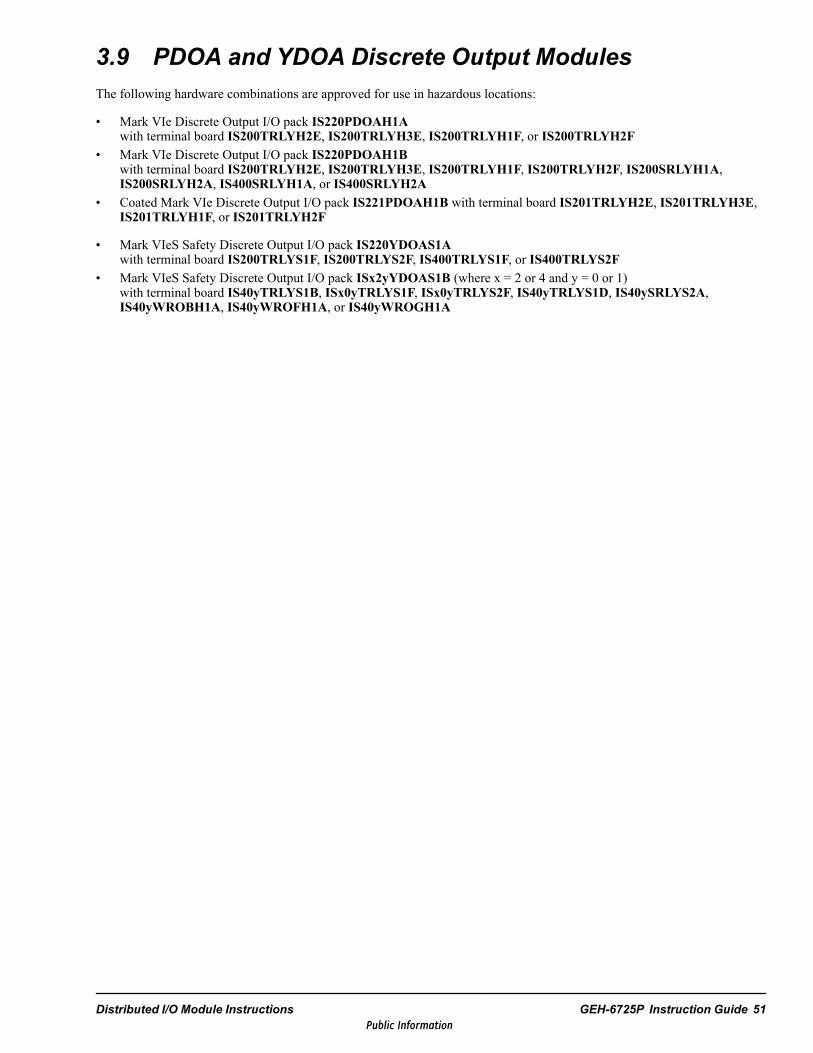
3.9 PDOA and YDOA Discrete Output ModulesThe following hardware combinations are approved for use in hazardous locations:
• Mark VIe Discrete Output I/O pack IS220PDOAH1Awith terminal board IS200TRLYH2E, IS200TRLYH3E, IS200TRLYH1F, or IS200TRLYH2F
• Mark VIe Discrete Output I/O pack IS220PDOAH1Bwith terminal board IS200TRLYH2E, IS200TRLYH3E, IS200TRLYH1F, IS200TRLYH2F, IS200SRLYH1A,IS200SRLYH2A, IS400SRLYH1A, or IS400SRLYH2A
• Coated Mark VIe Discrete Output I/O pack IS221PDOAH1B with terminal board IS201TRLYH2E, IS201TRLYH3E,IS201TRLYH1F, or IS201TRLYH2F
• Mark VIeS Safety Discrete Output I/O pack IS220YDOAS1Awith terminal board IS200TRLYS1F, IS200TRLYS2F, IS400TRLYS1F, or IS400TRLYS2F
• Mark VIeS Safety Discrete Output I/O pack ISx2yYDOAS1B (where x = 2 or 4 and y = 0 or 1)with terminal board IS40yTRLYS1B, ISx0yTRLYS1F, ISx0yTRLYS2F, IS40yTRLYS1D, IS40ySRLYS2A,IS40yWROBH1A, IS40yWROFH1A, or IS40yWROGH1A
Distributed I/O Module Instructions GEH-6725P Instruction Guide 51Public Information
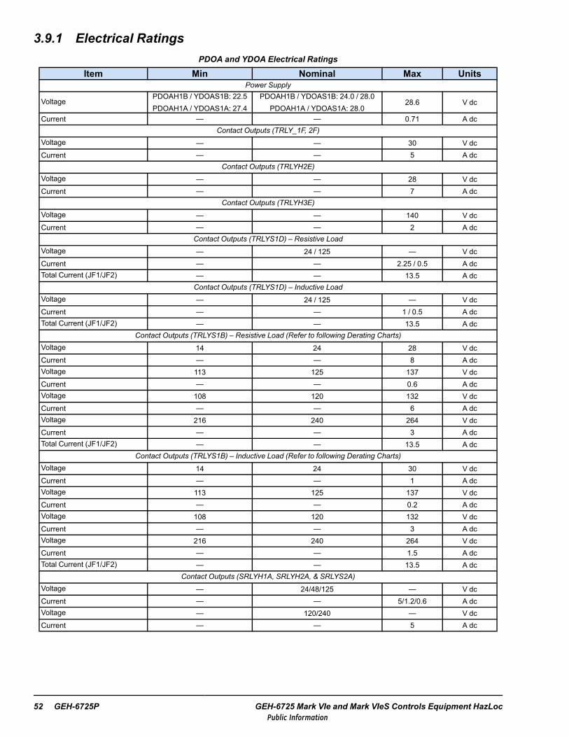
3.9.1 Electrical RatingsPDOA and YDOA Electrical Ratings
Item Min Nominal Max UnitsPower Supply
VoltagePDOAH1B / YDOAS1B: 22.5PDOAH1A / YDOAS1A: 27.4
PDOAH1B / YDOAS1B: 24.0 / 28.0PDOAH1A / YDOAS1A: 28.0
28.6 V dc
Current — — 0.71 A dcContact Outputs (TRLY_1F, 2F)
Voltage — — 30 V dcCurrent — — 5 A dc
Contact Outputs (TRLYH2E)Voltage — — 28 V dcCurrent — — 7 A dc
Contact Outputs (TRLYH3E)Voltage — — 140 V dcCurrent — — 2 A dc
Contact Outputs (TRLYS1D) – Resistive LoadVoltage — 24 / 125 — V dcCurrent — — 2.25 / 0.5 A dcTotal Current (JF1/JF2) — — 13.5 A dc
Contact Outputs (TRLYS1D) – Inductive LoadVoltage — 24 / 125 — V dcCurrent — — 1 / 0.5 A dcTotal Current (JF1/JF2) — — 13.5 A dc
Contact Outputs (TRLYS1B) – Resistive Load (Refer to following Derating Charts)Voltage 14 24 28 V dcCurrent — — 8 A dcVoltage 113 125 137 V dcCurrent — — 0.6 A dcVoltage 108 120 132 V dcCurrent — — 6 A dcVoltage 216 240 264 V dcCurrent — — 3 A dcTotal Current (JF1/JF2) — — 13.5 A dc
Contact Outputs (TRLYS1B) – Inductive Load (Refer to following Derating Charts)Voltage 14 24 30 V dcCurrent — — 1 A dcVoltage 113 125 137 V dcCurrent — — 0.2 A dcVoltage 108 120 132 V dcCurrent — — 3 A dcVoltage 216 240 264 V dcCurrent — — 1.5 A dcTotal Current (JF1/JF2) — — 13.5 A dc
Contact Outputs (SRLYH1A, SRLYH2A, & SRLYS2A)Voltage — 24/48/125 — V dcCurrent — — 5/1.2/0.6 A dcVoltage — 120/240 — V dcCurrent — — 5 A dc
52 GEH-6725P GEH-6725 Mark VIe and Mark VIeS Controls Equipment HazLocPublic Information

PDOA and YDOA Electrical Ratings (continued)
Item Min Nominal Max UnitsContact Outputs Fused via WROB, WROF, & WROG with SRLY
Voltage — 24/48/125 — V dcCurrent — — 2.25/1.2/0.6 A dcVoltage — 120/240 — V dcCurrent — — 2.25 A dcTotal Current WROB/WROG(JF1/JF2)
— — 13.5 A ac/dc
Total Current WROB (JG1) — — 5 A ac/dc
TRLYS1B Derating Charts
Distributed I/O Module Instructions GEH-6725P Instruction Guide 53Public Information

3.9.2 Field Wire ConnectionsFor discrete output terminal boards (accessories) certified for HazLoc, refer to the table Barrier-type Terminal Blocks for wiresize and screw torques.
3.9.3 Intrinsic Safety “ic” for Accessory Terminal Board IS40yTRLYS1D &IS40yTRLYS1B
Wiring Diagram
Nonhazardous Locationor
Hazardous (Classified) LocationClass I, Division 2, Groups A, B, C, and D
Class I, Zone 2, Group IICATEX Zone 2, Group IIC
ASSOCIATED APPARATUS WITH
ENTITY PARAMETERS:
Vmax => VocImax => Isc
Pi => PoCi + Ccable <= CaLi + Lcable <= La
IS40yTRLYS1D or IS40yTRLYS1B
INTRINSICALLY SAFE APPARATUS
RELAY CONTACTS
Nonhazardous Locationor
Hazardous (Classified) LocationClass I, Division 2, Groups A, B, C, and D
Class I, Zone 2, Group IICATEX Zone 2, Group IIC
Entity Parameters
Relay Contacts Value UnitVmax or Ui 24 VImax or Ii 261 mAPi 6.26 WCi 0 uFLi 0 mH
54 GEH-6725P GEH-6725 Mark VIe and Mark VIeS Controls Equipment HazLocPublic Information

IS400TRLYS1D Field TerminalsRelay Name TB1 Terminal Description
1
NC 1 Do Not UseCOM 2 Do Not UseNO 3 Field Solenoid +SOL 4 Field Solenoid -
2
NC 5 Do Not UseCOM 6 Do Not UseNO 7 Field Solenoid +SOL 8 Field Solenoid -
3
NC 9 Do Not UseCOM 10 Do Not UseNO 11 Field Solenoid +SOL 12 Field Solenoid -
4
NC 13 Do Not UseCOM 14 Do Not UseNO 15 Field Solenoid +SOL 16 Field Solenoid -
5
NC 17 Do Not UseCOM 18 Do Not UseNO 19 Field Solenoid +SOL 20 Field Solenoid -
6
NC 21 Do Not UseCOM 22 Do Not UseNO 23 Field Solenoid +SOL 24 Field Solenoid -
IS40yTRLYS1B Field Terminals
Output Terminal Relay TRLYS1B Outputs Output Terminal Relay TRLYS1B Outputs1
1
NC 25
7
NC2 COM 26 COM3 NO 27 NO4 SOL 28 —5
2
NC 29
8
NC6 COM 30 COM7 NO 31 NO8 SOL 32 —9
3
NC 33
9
NC10 COM 34 COM11 NO 35 NO12 SOL 36 —13
4
NC 37
10
NC14 COM 38 COM15 NO 39 NO16 SOL 40 —17
5
NC 41
11
NC18 COM 42 COM19 NO 43 NO20 SOL 44 —21
6
NC 45
12
NC22 COM 46 COM23 NO 47 NO24 SOL 48 SOL
Distributed I/O Module Instructions GEH-6725P Instruction Guide 55Public Information

3.9.4 Intrinsic Safety “ic” for Accessory Terminal BoardsISx0yTRLY_1F, ISx0yTRLY_2F
Wiring Diagram
Nonhazardous Locationor
Hazardous (Classified) LocationClass I, Division 2, Groups A, B, C, and D
Class I, Zone 2, Group IICATEX Zone 2, Group IIC
ASSOCIATED APPARATUS WITH
ENTITY PARAMETERS:
Vmax => VocImax => Isc
Pi => PoCi + Ccable <= CaLi + Lcable <= La
ASSOCIATED APPARATUS WITH
ENTITY PARAMETERS:
Vmax => VocImax => Isc
Pi => PoCi + Ccable <= CaLi + Lcable <= La
ISx0yTRLY_2F
INTRINSICALLY SAFE APPARATUS RELAY CONTACTS
ISx0yTRLY_1F
INTRINSICALLY SAFE APPARATUS
RELAY CONTACTS
Nonhazardous Locationor
Hazardous (Classified) LocationClass I, Division 2, Groups A, B, C, and D
Class I, Zone 2, Group IICATEX Zone 2, Group IIC
Entity Parameters
Relay Contacts Value UnitVmax or Ui 30 VImax or Ii 152 mAPi 4.56 WCi 0 uFLi 0 mH
56 GEH-6725P GEH-6725 Mark VIe and Mark VIeS Controls Equipment HazLocPublic Information

Field TerminalsName Terminal Name TerminalK1b TB1.2 K1a TB1.3K2b TB1.6 K2a TB1.7K3b TB1.10 K3a TB1.11K4b TB1.14 K4a TB1.15K5b TB1.18 K5a TB1.19K6b TB1.22 K6a TB1.23K7b TB2.26 K7a TB2.27K8b TB2.30 K8a TB2.31K9b TB2.34 K9a TB2.35K10b TB2.38 K10a TB2.39K11b TB2.42 K11a TB2.43K12b TB2.46 K12a TB2.47
Distributed I/O Module Instructions GEH-6725P Instruction Guide 57Public Information

3.9.5 Intrinsic Safety “ic” for Accessory Terminal Board ISx00SRLY
Wiring Diagram
!!"#$%%&#'!(#$##)%&*$#$&!+
,-./0, -./0 %/0%
1 23/ 1 23/
#&!)!4$%%&#'!
&$)"##!
!!"#$%%&#'!(#$##)%&*$#$&!+
,-./0, -./0 %/0%
1 23/ 1 23/
#&!)!4$%%&#'!
&$)"##!
ISx00SRLY
ISx00SRLY
Entity Parameters
Relay Contacts Value UnitVmax or Ui 30 VImax or Ii 152 mAPi 4.56 WCi 0 uFLi 0 mH
58 GEH-6725P GEH-6725 Mark VIe and Mark VIeS Controls Equipment HazLocPublic Information

ISx0ySRLYH1A/H2A Field Terminals
Relay Name Terminal Relay Name Terminal
1NC 1
7NC 25
COM 2 COM 26NO 3 NO 27
2NC 5
8NC 29
COM 6 COM 30NO 7 NO 31
3NC 9
9NC 33
COM 10 COM 34NO 11 NO 35
4NC 13
10NC 37
COM 14 COM 38NO 15 NO 39
5NC 17
11NC 41
COM 18 COM 42NO 19 NO 43
6NC 21
12NC 45
COM 22 COM 46NO 23 NO 47
IS40ySRLYS2A with WROB/WROF/WROG Field TerminalsOutputTerminal
Relay SRLY SRLY +WROB
SRLY/WROFwith Fuses
SRLY/WROFwithout Fuses
SRLY +WROG
1
1
NC NC NC NC NC2 COM COM COM (unfused) COM POWER3 NO NO NO NO NO4 SOL COM (fused) VSENSE RETURN5
2
NC NC NC NC NC6 COM COM COM (unfused) COM POWER7 NO NO NO NO NO8 SOL COM (fused) VSENSE RETURN9
3
NC NC NC NC NC10 COM COM COM (unfused) COM POWER11 NO NO NO NO NO12 SOL COM (fused) VSENSE RETURN13
4
NC NC NC NC NC14 COM COM COM (unfused) COM POWER15 NO NO NO NO NO16 SOL COM (fused) VSENSE RETURN17
5
NC NC NC NC NC18 COM COM COM (unfused) COM POWER19 NO NO NO NO NO20 SOL COM (fused) VSENSE RETURN21
6
NC NC NC NC NC22 COM COM COM (unfused) COM POWER23 NO NO NO NO NO24 SOL COM (fused) VSENSE RETURN25
7
NC NC NC NC NC26 COM COM COM (unfused) COM POWER27 NO NO NO NO NO28 COM (fused) VSENSE RETURN
Distributed I/O Module Instructions GEH-6725P Instruction Guide 59Public Information

IS40ySRLYS2A with WROB/WROF/WROG Field Terminals (continued)OutputTerminal
Relay SRLY SRLY +WROB
SRLY/WROFwith Fuses
SRLY/WROFwithout Fuses
SRLY +WROG
29
8
NC NC NC NC NC30 COM COM COM (unfused) COM POWER31 NO NO NO NO NO32 COM (fused) VSENSE RETURN33
9
NC NC NC NC NC34 COM COM COM (unfused) COM POWER35 NO NO NO NO NO36 COM (fused) VSENSE RETURN37
10
NC NC NC NC NC38 COM COM COM (unfused) COM POWER39 NO NO NO NO NO40 COM (fused) VSENSE RETURN41
11
NC NC NC NC NC42 COM COM COM (unfused) COM POWER43 NO NO NO NO NO44 COM (fused) VSENSE RETURN45
12
NC NC NC NC NC46 COM COM COM (unfused) COM POWER47 NO NO NO NO NO48 SOL COM (fused) VSENSE RETURN
60 GEH-6725P GEH-6725 Mark VIe and Mark VIeS Controls Equipment HazLocPublic Information

3.10 PHRA and YHRA HART® Enabled I/O ModulesThe following hardware combinations are approved for use in hazardous locations:
• HART enabled I/O pack IS220PHRAH1A or IS220PHRAH1Bwith terminal boards (accessories) IS200SHRAH1A or IS200SHRAH2A
• Coated HART enabled I/O pack IS221PHRAH1B with terminal boards (accessories) IS201SHRAH1A orIS201SHRAH2A
• Discrete output I/O pack IS220YHRAS1Awith terminal board (accessory) IS200SHRAS1A or IS200SHRAS2A
3.10.1 Electrical RatingsItem Min Nominal Max Units
Power SupplyVoltage 27.4 28.0 28.6 V dcCurrent — — 0.5 A dc
Analog Inputs (1-8)Voltage -5 — 5 V dcCurrent 0 — 20 mA dc
Analog Inputs (9-10)Voltage -5 — 5 V dcCurrent -1 — 20 mA dc
Analog OutputsVoltage 0 — 16.3 V dcCurrent 0 — 20 mA dc
Analog Transmitter PowerVoltage 22.8 24.0 25.2 V dcCurrent — — 21 mA dc
3.10.2 Field Wire ConnectionsFor HART analog input terminal boards (accessories) certified for HazLoc, refer to the table Euro Style Box-type TerminalBlocks for wire size and screw torques.
Distributed I/O Module Instructions GEH-6725P Instruction Guide 61Public Information

3.11 PPRA Emergency Turbine Protection ModuleThe following I/O pack and terminal board combinations are approved for use in hazardous locations:
• Turbine protection I/O pack IS220PPRAH1Awith terminal board (accessory) IS200TREAH1A and daughter board (accessory) IS200WREAH1A
• Turbine protection I/O pack IS220PPRAS1A or IS220PPRAS1Bwith terminal board (accessory) IS200TREAS1A and daughter board (accessory) IS200WREAS1A
3.11.1 Electrical RatingsItem Min Nominal Max Units
Power SupplyVoltage 27.4 28.0 28.6 V dcCurrent — — 0.5 A dc
Contact Inputs (TREA)Voltage 0 — 32 V dc
Voltage Detection Inputs (TREA)Voltage 16 — 140 V dc
E-stop Input (TREA)Voltage 18 — 140 V dc
Speed Inputs (TREA, WREA)Voltage -15 — 15 V dc
Contact Outs 1-2 (TREA)Voltage — — 28 V dcCurrent — — 7 A dc
Contact Out 3 (WREA)Voltage — — 28 V dcCurrent — — 5 A dc
Contact Wetting Outputs (WREA)Voltage — — 32 V dcCurrent — — 13.2 mA dc
3.11.2 Field Wire ConnectionsFor the TREA terminal board (accessory) certified for HazLoc, refer to the table Euro Style Box-type Terminal Blocks for wiresize and screw torques.
62 GEH-6725P GEH-6725 Mark VIe and Mark VIeS Controls Equipment HazLocPublic Information

3.12 PPRF PROFIBUS® Master Gateway ModuleThe following I/O pack and terminal board combinations are approved for use in hazardous locations:
• Analog output pack IS220PPRFH1A or IS220PPRFH1Bwith accessory ID board IS200SPIDG1A
3.12.1 Electrical RatingsPower Supply
Item Min Nominal Max UnitsVoltage 27.4 28.0 28.6 V dcCurrent — — 0.18 A dc
Distributed I/O Module Instructions GEH-6725P Instruction Guide 63Public Information

3.13 PPRO and YPRO Backup Turbine ProtectionModulesThe following I/O pack and terminal board combinations are approved for use in hazardous locations:
• Mark VIe Backup turbine protection I/O pack IS220PPROH1Awith terminal boards (accessories) IS200SPROH1A, IS200SPROH2A, IS200TPROH1C, IS200TPROH2C,IS200TREAH1A, IS200TREAH3A
• Mark VIe Backup turbine protection I/O pack IS220PPROS1Bwith terminal boards (accessories) IS200SPROH1A, IS200SPROH2A, IS200TPROH1C, IS200TPROH2C,IS200TPROS1C, IS200TPROS2C, IS200TREAH1A, IS200TREAH3A
• Mark VIeS Backup turbine protection I/O pack IS220YPROS1Awith terminal boards (accessories) IS200SPROS1A, IS200TPROS1C, IS200TPROS2C, IS200TREAS1A
3.13.1 Electrical RatingsItem Min Nominal Max Units
Power SupplyVoltage 27.4 28.0 28.6 V dcCurrent — — 0.37 A dc
Voltage Detection Inputs (TREA)Voltage 16 — 140 V dc
E-stop Input (TREA)Voltage 18 — 140 V dc
PT Inputs (SPRO, TPRO)Voltage 0 — 138 VacFrequency 5 — 66 Hz
Speed Inputs (SPRO, TPRO, TREA)Voltage -15 — 15 V dc
Contact Out (TREA)Voltage — — 28 V dcCurrent — — 7 A dc
Speed Sensor Power Output (TPRO)Voltage 22.8 24.0 25.2 VCurrent — — 25 mA
3.13.2 Field Wire ConnectionsFor SPROH2A, TPRO_2A, and TREAH3A terminal boards (accessories) certified for HazLoc, refer to the table Euro StyleBox-type Terminal Blocks for wire size and screw torques.
For SPRO_1A, TPRO_1A, TREA_1A terminal boards (accessories) certified for HazLoc, refer to the table Barrier-typeTerminal Blocks for wire size and screw torques.
64 GEH-6725P GEH-6725 Mark VIe and Mark VIeS Controls Equipment HazLocPublic Information

3.14 PRTD Resistance Temperature Device Input ModuleThe following I/O pack and terminal board combinations are approved for use in hazardous locations:
• RTD input pack IS220PRTDH1A or IS220PRTDH1Bwith terminal board IS200TRTDH2D, IS200SRTDH1A, or IS200SRTDH2A
• Coated RTD input pack IS221PRTDH1B with terminal board IS201TRTDH2D, IS201SRTDH1A, orIS201SRTDH2A
3.14.1 Electrical RatingsItem Min Nominal Max Units
Power SupplyVoltage 27.4 28.0 28.6 VCurrent — — 0.24 A
RTD InputsVoltage 0 — 4.2 VCurrent — 10.0 — mA
3.14.2 Field Wire ConnectionsTerminal Board Terminal Block TypeSRTD Refer to the table Euro Style Box-type Terminal Blocks for wire size and screw torques.
TRTD Refer to the table Barrier-type Terminal Blocks for wire size and screw torques.
3.14.3 Intrinsic Safety “ic”Wiring Diagram
ASSOCIATED APPARATUSRTD INPUTS
Hazardous (Classified) LocationClass I, Division 2, Groups A, B, C,
and DClass I, Zone 2, Group IICATEX Zone 2, Group IIC
INTRINSICALLY SAFE APPARATUS WITH ENTITY
PARAMETERS:
Vmax => VocImax => Isc
Pi => PoCi + Ccable <= CaLi + Lcable <= La
ORSIMPLE APPARATUS
+
-
S
Nonhazardous Locationor
Hazardous (Classified) LocationClass I, Division 2, Groups A, B, C, and D
Class I, Zone 2, Group IICATEX Zone 2, Group IIC
Distributed I/O Module Instructions GEH-6725P Instruction Guide 65Public Information

Entity Parameters
RTD Inputs Value UnitVoc or Uo 15 VIsc or Io 10 mAPo 0.15 WCa or Co 3 uFLa or Lo 100 mH
Note 1. This associated apparatus may also be connected to simple apparatus as defined in Article 504.2 and installed andtemperature classified in accordance with Article 504.10(B) of the National Electrical Code (ANSI/NFPA 70), or other localcodes, as applicable.
Note 2. Only resistive simple apparatus (such as RTDs) shall be connected to RTD inputs.
Note 3. Each cable used to connect the simple apparatus must have suitable insulation as required by the applicable localelectrical codes.
Note 4. Signal terminal (S) may be grounded.
Note 5. The maximum cable length connecting each RTD to the device shall not exceed 1000 ft.
Field TerminalsAccessory TB Name (+) Terminal Name (S) Terminal Name (-)Terminal
SCLS or TRTD
RTDEXC1 TB1.1 RTDSIG1 TB1.2 RTDRET1 TB1.3RTDEXC2 TB1.4 RTDSIG2 TB1.5 RTDRET2 TB1.6RTDEXC3 TB1.7 RTDSIG3 TB1.8 RTDRET3 TB1.9RTDEXC4 TB1.10 RTDSIG4 TB1.11 RTDRET4 TB1.12RTDEXC5 TB1.13 RTDSIG5 TB1.14 RTDRET5 TB1.15RTDEXC6 TB1.16 RTDSIG6 TB1.17 RTDRET6 TB1.18RTDEXC7 TB1.19 RTDSIG7 TB1.20 RTDRET7 TB1.21RTDEXC8 TB1.22 RTDSIG8 TB1.23 RTDRET8 TB1.24
TRTD
RTDEXC9 TB2.25 RTDSIG9 TB2.26 RTDRET9 TB2.27RTDEXC10 TB2.28 RTDSIG10 TB2.29 RTDRET10 TB2.30RTDEXC11 TB2.31 RTDSIG11 TB2.32 RTDRET11 TB2.33RTDEXC12 TB2.34 RTDSIG12 TB2.35 RTDRET12 TB2.36RTDEXC13 TB2.37 RTDSIG13 TB2.38 RTDRET13 TB2.39RTDEXC14 TB2.40 RTDSIG14 TB2.41 RTDRET14 TB2.42RTDEXC15 TB2.43 RTDSIG15 TB2.44 RTDRET15 TB2.45RTDEXC16 TB2.46 RTDSIG16 TB2.47 RTDRET16 TB2.48
66 GEH-6725P GEH-6725 Mark VIe and Mark VIeS Controls Equipment HazLocPublic Information

3.15 PSCA Serial Communications ModuleThe following I/O pack and terminal board combinations are approved for use in hazardous locations:
• Serial communication I/O pack IS220PSCAH1A or IS220PSCAH1B with accessory terminal boardIS200SSCAH1A or IS200SSCAH2A
• Coated serial communication I/O pack IS221PSCAH1B with accessory terminal board IS201SSCAH1A orIS201SSCAH2A
• Serial communication I/O pack IS42yPSCAH1B with accessory terminal board IS40ySSCAH1A orIS40ySSCAH2A (where y = 0 or 1)
3.15.1 Electrical RatingsPower Supply
Item Min Nominal Max Units
Voltage PSCAH1B: 22.5PSCAH1A: 27.4
PSCAH1B: 24.0 / 28.0PSCAH1A: 28.0
28.6 V
Current — — 0.36 A
3.15.2 Field Wire ConnectionsFor serial communication terminal boards (accessories) certified for HazLoc, refer to the table Euro Style Box-type TerminalBlocks for wire size and screw torques.
Distributed I/O Module Instructions GEH-6725P Instruction Guide 67Public Information
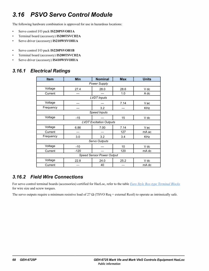
3.16 PSVO Servo Control ModuleThe following hardware combination is approved for use in hazardous locations:
• Servo control I/O pack IS220PSVOH1A• Terminal board (accessory) IS200TSVCH2A• Servo driver (accessory) IS210WSVOH1A
• Servo control I/O pack IS220PSVOH1B• Terminal board (accessory) IS200TSVCH2A• Servo driver (accessory) IS410WSVOH1A
3.16.1 Electrical RatingsItem Min Nominal Max Units
Power SupplyVoltage 27.4 28.0 28.6 V dcCurrent — — 1.0 A dc
LVDT InputsVoltage — — 7.14 Vac
Frequency — 3.2 — KHzSpeed Inputs
Voltage -15 — 15 V dcLVDT Excitation Outputs
Voltage 6.86 7.00 7.14 V acCurrent — — 127 mA ac
Frequency 3.0 3.2 3.4 KHzServo Outputs
Voltage -10 — 10 V dcCurrent -120 — 120 mA dc
Speed Sensor Power OutputVoltage 22.8 24.0 25.2 V dcCurrent — 40 — mA dc
3.16.2 Field Wire ConnectionsFor servo control terminal boards (accessories) certified for HazLoc, refer to the table Euro Style Box-type Terminal Blocksfor wire size and screw torques.
The servo outputs require a minimum resistive load of 27 Ω (TSVO Req + external Rcoil) to operate as intrinsically safe.
68 GEH-6725P GEH-6725 Mark VIe and Mark VIeS Controls Equipment HazLocPublic Information

3.17 PTCC and YTCC Thermocouple Input ModulesThe following hardware combinations are approved for use in hazardous locations:
• Mark VIe Thermocouple input pack IS220PTCCH1A or IS220PTCCH1Bwith terminal boards (accessories) IS200STTCH1A, IS200STTCH2A, IS200TBTCH1B, or IS200TBTCH1C
• Mark VIeS Safety Thermocouple input pack IS220YTCCS1Awith terminal boards IS200STTCS1A, IS400STTCS1A, IS200STTCS2A, IS400STTCS2A, IS200TBTCS1B,IS200TBTCS1C, or IS400TBTCS1C
3.17.1 Electrical RatingsItem Min Nominal Max Units
Power SupplyVoltage 27.4 28.0 28.6 V dcCurrent — — 0.16 A dc
Thermocouple InputsVoltage -8 — 45 mV dc
3.17.2 Field Wire ConnectionsTerminal Board Terminal Block TypeSTTC Refer to the table Euro Style Box-type Terminal Blocks for wire size and screw torques.TBTC Refer to the table Barrier-type Terminal Blocks for wire size and screw torques.
3.17.3 Intrinsic Safety “ic”Wiring Diagram
ASSOCIATED APPARATUSTHERMOCOUPLE INPUTS
INTRINSICALLY SAFE APPARATUS WITH ENTITY
PARAMETERS:
Vmax => VocImax => Isc
Pi => PoCi + Ccable <= CaLi + Lcable <= La
ORSIMPLE APPARATUS
-BIAS
+BIAS
-
+
Hazardous (Classified) LocationClass I, Division 2, Groups A, B, C, and D
Class I, Zone 2, Group IICATEX Zone 2, Group IIC
Nonhazardous Locationor
Hazardous (Classified) LocationClass I, Division 2, Groups A, B, C, and D
Class I, Zone 2, Group IICATEX Zone 2, Group IIC
+
-
SHIELD
Distributed I/O Module Instructions GEH-6725P Instruction Guide 69Public Information

Entity Parameters
Thermocouple Inputs Value UnitVoc or Uo 0.5 VIsc or Io 25 nAPo 13 nWCa or Co 1000 uFLa or Lo 100 mH
Note 1. This associated apparatus may also be connected to simple apparatus as defined in Article 504.2 and installed andtemperature classified in accordance with Article 504.10(B) of the National Electrical Code (ANSI/NFPA 70), or other localcodes, as applicable.
Note 2. Only resistive simple apparatus (such as thermocouples) shall be connected to thermocouple inputs.
Note 3. Each cable used to connect the simple apparatus must have suitable insulation as required by the applicable localelectrical codes.
Note 4. The maximum cable length connecting each thermocouple to the device shall not exceed 1000 ft.
Field Terminals with STTCName (+) Terminal Name (-)TerminalInput 1 (+) TB1.1 Input 1 (-) TB1.2Shield TB1.3 Shield TB1.4Input 2 (+) TB1.5 Input 2 (-) TB1.6Input 3 (+) TB1.7 Input 3 (-) TB1.8Shield TB1.9 Shield TB1.10Input 4 (+) TB1.11 Input 4 (-) TB1.12Input 5 (+) TB1.13 Input 5 (-) TB1.14Shield TB1.15 Shield TB1.16Input 6 (+) TB1.17 Input 6 (-) TB1.18Input 7 (+) TB1.19 Input 7 (-) TB1.20Shield TB1.21 Shield TB1.22Input 8 (+) TB1.23 Input 8 (-) TB1.24Input 9 (+) TB1.25 Input 9 (-) TB1.26Shield TB1.27 Shield TB1.28Input 10 (+) TB1.29 Input 10 (-) TB1.30Input 11 (+) TB1.31 Input 11 (-) TB1.32Shield TB1.33 Shield TB1.34Input 12 (+) TB1.35 Input 12 (-) TB1.36No Connect TB1.37 No Connect TB1.38No Connect TB1.39 No Connect TB1.40Shield TB1.41 Shield TB1.42
70 GEH-6725P GEH-6725 Mark VIe and Mark VIeS Controls Equipment HazLocPublic Information

Field Terminals with TBTCName (+) Terminal Name (-)TerminalInput 1 (+) TB1.1 Input 1 (-) TB1.2Input 2 (+) TB1.3 Input 2 (-) TB1.4Input 3 (+) TB1.5 Input 3 (-) TB1.6Input 4 (+) TB1.7 Input 4 (-) TB1.8Input 5 (+) TB1.9 Input 5 (-) TB1.10Input 6 (+) TB1.11 Input 6 (-) TB1.12Input 7 (+) TB1.13 Input 7 (-) TB1.14Input 8 (+) TB1.15 Input 8 (-) TB1.16Input 9 (+) TB1.17 Input 9 (-) TB1.18Input 10 (+) TB1.19 Input 10 (-) TB1.20Input 11 (+) TB1.21 Input 11 (-) TB1.22Input 12 (+) TB1.23 Input 12 (-) TB1.24Input 13 (+) TB2.25 Input 13 (-) TB2.26Input 14 (+) TB2.27 Input 14 (-) TB2.28Input 15 (+) TB2.29 Input 15 (-) TB2.30Input 16 (+) TB2.31 Input 16 (-) TB2.32Input 17 (+) TB2.33 Input 17 (-) TB2.34Input 18 (+) TB2.35 Input 18 (-) TB2.36Input 19 (+) TB2.37 Input 19 (-) TB2.38Input 20 (+) TB2.39 Input 20 (-) TB2.40Input 21 (+) TB2.41 Input 21 (-) TB2.42Input 22 (+) TB2.43 Input 22 (-) TB2.44Input 23 (+) TB2.45 Input 23 (-) TB2.46Input 24 (+) TB2.47 Input 24 (-) TB2.48
Distributed I/O Module Instructions GEH-6725P Instruction Guide 71Public Information

3.18 PTUR and YTUR Turbine Specific Primary TripModulesThe following hardware combinations are approved for use in hazardous locations:
• Mark VIe Turbine Specific Primary Trip I/O pack IS220PTURH1A or IS220PTURH1Bwith terminal board (accessory) IS200TRPAH1A
• Mark VIeS Turbine Specific Primary Trip I/O pack IS220YTURS1A or IS220YTURS1B‡
with terminal board (accessory) IS200TRPAS1A
Note ‡ Contact GE for hardware availability.
3.18.1 Electrical CharacteristicsItem Min Nominal Max Units
Power SupplyVoltage 27.4 28.0 28.6 V dcCurrent — — 0.41 A dc
Voltage Detection Inputs (TRPA)Voltage 16 — 140 V dc
E-stop Input (TRPA)Voltage 18 — 140 V dc
Speed Inputs (TRPA)Voltage -15 — 15 V dc
E-stop Power OutputVoltage (O.C.) — 28 — V dcCurrent (S.C.) — 17 — mA dc
Contact Out (TRPA)Voltage — 24 28 V dcCurrent — — 7 A dc
3.18.2 Field Wire ConnectionsFor the TRPA_1A terminal board (accessory) certified for HazLoc, refer to the table Euro Style Box-type Terminal Blocks forwire size and screw torques.
72 GEH-6725P GEH-6725 Mark VIe and Mark VIeS Controls Equipment HazLocPublic Information

3.19 PUAA/YUAA Universal Analog I/O ModuleThe following hardware combinations are approved for use in hazardous locations where the ambient temperature (Ta) doesnot exceed the range -40 to 70°C (-40 to 158 °F):
• Mark VIe Universal Analog I/O pack IS42yPUAAH1Awith terminal boards (accessory) IS41ySUAAH1A• Mark VIeS Safety Universal Analog I/O pack IS42yYUAAS1Awith terminal boards (accessory) IS41ySUAAS1A
3.19.1 Electrical RatingsItem Min Nominal Max Units
Power SupplyVoltage 25.2 28.0 30.8 V dcCurrent — 0.7 — A dc
Analog InputsVoltage -5 — 5 V dcVoltage -10 — 10 V dcCurrent 0 — 24 mA dc
Thermocouple InputsVoltage -154 — 154 mV dc
RTD InputsVoltage 0 — 4 V dcCurrent — 1 — mA dc
Analog OutputsVoltage 0 — 22 V dcCurrent 0 — 24 mA dc
3.19.2 Field Wire ConnectionsFor Universal Analog I/O terminal boards (accessories) certified for HazLoc, refer to the table Euro Style Box-type TerminalBlocks for wire size and screw torques.
The power supply terminals are rated for wire size AWG 28 to 14, and screw torque 1.7 in-lb (0.19 Nm).
Distributed I/O Module Instructions GEH-6725P Instruction Guide 73Public Information

3.19.3 PUAA/YUAA— Intrinsic Safety “ic” for Thermocouple InputsWiring Diagram
!"# !"#
$%&'(!)"&*+,! -.,/-0%'1-2--,&
! -3,"/-0%'1
,4$%&'+,%
$%&' (!)"&*+,!-.,/-0%'1-2--,&
!-3,"/-0%'1
5
2
Entity Parameters
Thermocouple Input Value UnitVoc or Uo 24.5 V
Isc or Io 34.5 uA
Po 395 uW
Ca or Co 0.42 uF
La or Lo 100 mH
Note 1. This associated apparatus may also be connected to simple apparatus as defined in Article 504.2 and installed andtemperature classified in accordance with Article 504.10(B) of the National Electrical Code (ANSI/NFPA 70), or other localcodes, as applicable.
Note 2. Only resistive simple apparatus (such as thermocouples) shall be connected to thermocouple inputs.
Note 3. Each cable used to connect the simple apparatus must have suitable insulation as required by the applicable localelectrical codes.
Note 4. The maximum cable length connecting each thermocouple to the device shall not exceed 304.8 m (1,000 ft).
74 GEH-6725P GEH-6725 Mark VIe and Mark VIeS Controls Equipment HazLocPublic Information

3.19.4 PUAA/YUAA— Intrinsic Safety “ic” for RTD InputsWiring Diagram
RTD
Entity Parameters
RTD Input Value UnitVoc or Uo 24.5 V
Isc or Io 3.03 mA
Po 74.2 mW
Ca or Co 0.42 uF
La or Lo 100 mH
Note 1. This associated apparatus may also be connected to simple apparatus as defined in Article 504.2 and installed andtemperature classified in accordance with Article 504.10(B) of the National Electrical Code (ANSI/NFPA 70), or other localcodes, as applicable.
Note 2. Only resistive simple apparatus (such as RTDs) shall be connected to RTD inputs.
Note 3. Each cable used to connect the simple apparatus must have suitable insulation as required by the applicable localelectrical codes.
Note 4. The maximum cable length connecting each RTD to the device shall not exceed 304.8 m (1,000 ft).
Distributed I/O Module Instructions GEH-6725P Instruction Guide 75Public Information

3.19.5 PUAA/YUAA— Intrinsic Safety “ic” for Voltage InputsWiring Diagram
!!"#$%%&#'!(#$##)%&*$#$&!+
,-./0, -./0 %/0%
1 23/1 23/
#&!)!4$%%&#'!
,"#$%'#
"
"
Input Parameters
Voltage Input Value UnitVmax or Ui 19 and -10 V
Imax or Ii 0.2 A
Pi 1 W
Ci 5.6 nF
Li 0 —
Output Parameters
Voltage Output Value Unit
Voc or Uo 24.5 V
Isc or Io 29.4 uA
Po 180 uW
Ca or Co 0.42 uF
La or Lo 100 mH
76 GEH-6725P GEH-6725 Mark VIe and Mark VIeS Controls Equipment HazLocPublic Information

3.19.6 PUAA/YUAA— Intrinsic Safety “ic” for 4 to 20 mA InputsWiring Diagram
!!"#$%%&#'!(#$##)%&*$#$&!+
,-./0, -./0 %/0%
1 23/1 23/
#&!)!4$%%&#'!
56-%'#
"
"
Input Parameters
4 to 20 mA Input Value UnitVmax or Ui 50 V
Imax or Ii 24 mA
Pi 1 W
Ci 5.6 nF
Li 0 —
Output Parameters
4 to 20 mA Output Value UnitVoc or Uo 24.5 V
Isc or Io 29.4 uA
Po 180 uW
Ca or Co 0.42 uF
La or Lo 100 mH
Distributed I/O Module Instructions GEH-6725P Instruction Guide 77Public Information

3.19.7 PUAA/YUAA— Intrinsic Safety “ic” for 4 to 20 mA Inputs withTransmitter Power Outputs
Wiring Diagram
!"#$#%&''"!(#)!&!!$'"*&!&"#+
,-./0, -./0 '/0'
1 23/1 23/
##4!&''"!(#56-'(!)!!"#*!!&"
'4)&"4(!'(!
4
')"
4"&!("
#
Entity Parameters
Transmitter Power Output Value UnitVoc or Uo 24.5 V
Isc or Io 24.1 mA
Po 0.59 W
Ca or Co 100 nF
La or Lo 0.15 mH
Note 1. Connect the transmitter power input to the DAC terminal of the associated apparatus.
Note 2. For 3-wire transmitters, connect the power return to the IOB terminal of the associated apparatus.
78 GEH-6725P GEH-6725 Mark VIe and Mark VIeS Controls Equipment HazLocPublic Information

3.19.8 PUAA/YUAA— Intrinsic Safety “ic” for 0 to 20 mA OutputsWiring Diagram
!"#$#%&''"!(#)!&!!$'"*&!&"#+
,-./0, -./0 '/0'
1 23/1 23/
##4!&''"!(#
55-4(!'(!
4
4
Entity Parameters
0 to 20 mA Output Value UnitVoc or Uo 24.5 V
Isc or Io 24.1 mA
Po 0.59 W
Ca or Co 100 nF
La or Lo 0.15 mH
Distributed I/O Module Instructions GEH-6725P Instruction Guide 79Public Information

3.19.9 PUAA/YUAA— Discrete Inputs with Switch Power Output forExternally Fed Inputs
Wiring Diagram
!"#$#%&''"!(#)!&!!$'"*&!&"#+
,-./0, -./0 '/0'
1 23/1 23/
##4!&''"!(#
&.)
4
56774-
4"&!("
#
Note The 12500 Ohm input resistor is not present in the Discrete Input Pulse Accumulator configuration.
Entity Parameters
Transmitter Power Output Value UnitVoc or Uo 30 V
Isc or Io 2.4 mA
Po 180 uW
Ca or Co 0.42 uF
La or Lo 100 mH
80 GEH-6725P GEH-6725 Mark VIe and Mark VIeS Controls Equipment HazLocPublic Information

3.19.10 PUAA/YUAA— Discrete Inputs with Switch Power Output forInternally Fed Inputs
Wiring Diagram
!"#$#%&''"!(#)!&!!$'"*&!&"#+
,-./0, -./0 '/0'
1 23/1 23/
##4!&''"!(#
)
4
564-
4
"&!("
#
Entity Parameters
Transmitter Power Output Value UnitVoc or Uo 24.5 V
Isc or Io 24.1 mA
Po 0.59 W
Ca or Co 100 nF
La or Lo 0.15 mH
Distributed I/O Module Instructions GEH-6725P Instruction Guide 81Public Information

3.19.11 PUAA/YUAA— Field Wiring Terminals
!"
!"
!"
!"
!"
!"
!"
!"
#
!"
!"
!"
#
!"
!"
!"
!"
!"
# #
!"
!"
!"
!"
!"
!"
!"
!"
!"
!"
!"
!"
!"
!"
!"
!"
Note All field terminal wires must be rated for temperatures of 105°C or greater.
82 GEH-6725P GEH-6725 Mark VIe and Mark VIeS Controls Equipment HazLocPublic Information

3.20 PVIB and YVIB Vibration Monitor ModulesThe following hardware combinations are approved for use in hazardous locations:
• Mark VIe Vibration Monitor I/O pack IS220PVIBH1Awith terminal board (accessory) IS200TVBAH2A and three negative power supply daughterboards (accessories)IS200WNPSH1A
• Mark VIe Vibration Monitor I/O pack IS420PVIBH1Bwith terminal board (accessory) ) IS200TVBAH2A and three negative power supply daughterboards (accessories)IS200WNPSH1A, IS400WNPSH1A, or IS40yTVBAH2B
• Mark VIeS Vibration Monitor I/O pack IS220YVIBS1Awith terminal board IS200TVBAS2A and three negative power supply daughterboards (accessories) IS200WNPSS1A
• Mark VIeS Vibration Monitor I/O pack IS42yYVIBS1B (where y = 0 or 1)with terminal board ISx0yTVBAS2A (where x = 2 or 4 and y = 0 or 1) and three negative power supply daughterboards(accessories) ISx0yWNPSS1A, or IS40yTVBAS2B
3.20.1 Electrical RatingsItem Min Nominal Max Units
Power Supply
Voltage PVIBH1B / YVIBS1B: 27.4PVIBH1A / YVIBS1A: 27.4
PVIBH1B / YVIBS1B: 28.0PVIBH1A / YVIBS1A: 28.0
28.6 V dc
Current — — 0.98 A dcVibration Inputs
Voltage -20 — 15.6 V dcPosition Inputs
Voltage -20 — -0.5 V dcBuffered Outputs
Voltage -20 — 4.5 V dcCurrent -3 — — mA dc
Probe PowerVoltage -25.2 -24 -22.8 V dcCurrent — — 12 mA dc
Distributed I/O Module Instructions GEH-6725P Instruction Guide 83Public Information

3.21 YSIL Core Safety Protection ModuleThe following hardware combination is approved for use in hazardous locations:
Mark VIeS YSIL Core Safety Protection I/O pack IS220YSILS1A and IS220YSILS1B, with Core Protection TerminalBoard (accessory) IS200TCSAS1A and daughterboard (accessory) IS200WCSAS1A and I/O Expansion Board(accessory) IS200SCSAS1A
3.21.1 Electrical Ratings
Item Min Nominal Max UnitsYSIL Power Supply In
Voltage 27.4 28 28.6 V dc
Current - - 1 A dc
SCSA Power Supply In
Voltage 27.4 28 28.6 V dc
Current - - 0.75 A dc
TCSA E-Stop In
Voltage 18 - 32 V dc
TCSA E-Stop Wetting Power Out
Voltage - 24 - V dc
Current - - 100 mA dc
TCSA Solenoid Out - Pilot Duty
Voltage - 24 30 V dc
Current - - 2 A dc
TCSA Contact Out
Voltage - 24 30 V dc
Current - - 5 A
TCSA PT In
Voltage - - 138 V ac
Frequency 5 - 66 Hz
TCSA Contact In
Voltage 0 24 32 V dc
TCSA Contact Wetting Power Out
Voltage 18 24 32 V dc
Current - - 3 mA dc
TCSA Speed In
Voltage - - +/- 15 V pk
Frequency 2 - 20k Hz
WCSA Reuter Stokes FD / Analog In
Current 0 - 20 mA dc
84 GEH-6725P GEH-6725 Mark VIe and Mark VIeS Controls Equipment HazLocPublic Information

Item Min Nominal Max UnitsWCSA Reuter Stokes FD / Analog Transducer Power Out
Voltage - 24 - V dc
Current - - 21 mA dc
WCSA Speed Repeater Out
Voltage +/- 5 V pk
Current - - 250 mA dc
SCSA Contact In
Voltage 0 24 32 V dc
SCSA Contact Wetting Power Out
Voltage 18 24 32 V dc
Current - - 3 mA dc
SCSA Contact Out
Voltage 24 30 V dc
Current 5 A
SCSA Analog In
Current 0 - 20 mA dc
SCSA Analog Transducer Power Out
Voltage - 24 - V dc
Current - - 21 mA dc
SCSAThermocouple In
Voltage -8 - 45 mV dc
3.21.2 Field Wire ConnectionsFor TCSA, WCSA, and SCSA (accessories) certified for HazLoc, refer to the table Euro Style Box-type Terminal Blocks forwire size and screw torques.
Caution
Add external suppression diode to each solenoid coil to ensure non-sparking behaviorof this equipment.
Note TCSA Honeywell Flame Detector Inputs are not approved for use in Hazardous Locations.
Distributed I/O Module Instructions GEH-6725P Instruction Guide 85Public Information

3.21.3 Intrinsic Safety “ic” for Accessory Terminal Board ModelsIS200TCSAS1A, IS200SCSAS1A
Wiring Diagram
!!"#$%%&#'!(#$##)%&*$#$&!+
,-./0, -./0 %/0%
1 23/ 1 23/
#&!)!4$%%&#'!
&$)"##!
!!"#$%%&#'!(#$##)%&*$#$&!+
,-./0, -./0 %/0%
1 23/ 1 23/
#&!)!4$%%&#'!
&$)"##!
ISx00TCSAS1A or ISx00SCSAS1A
ISx00TCSAS1A or ISx00SCSAS1A
Entity Parameters
Relay Contacts Value Unit
Vmax or Ui 30 V
Imax or Ii 152 mA
Pi 4.56 W
Ci 0 uF
Li 0 mH
86 GEH-6725P GEH-6725 Mark VIe and Mark VIeS Controls Equipment HazLocPublic Information

Field Terminals
Board Name Terminal
TCSA
D01_NO 1
D01_COM 3
D01_NC 5
D02_NO 2
D02_COM 4
D02_NC 6
SCSA
K1NC 45
K1C 47
K1NO 49
K2NC 46
K2C 48
K2NO 50
Note 1. For North American locations, if contact wetting power is supplied to the accessory terminal board throughconnector J1, the wire harness specified on drawing 336A4937FJ shall be used, and the wetting power source shall be currentlimited by either a UL recognized fuse rated at not more than 3 A, or one of the following power supplies:
•UL R/C, Phoenix Contact GmbH & Co Kg, model QUINT-PS-100-240AC/24DC/5 GE
•UL R/C, Convertec Ltd., model TIS 150-124
Note 2. For North American locations, if solenoid power is supplied to the accessory terminal board through connector J2 orJ3, the wire harness specified on drawing 336A4937EP shall be used, and the solenoid power source shall be current limitedby either a UL recognized fuse rated at not more than 3 A, or one of the following power supplies:
•UL R/C, Phoenix Contact GmbH & Co Kg, model QUINT-PS-100-240AC/24DC/5 GE
•UL R/C, Convertec Ltd., model TIS 150-124
Distributed I/O Module Instructions GEH-6725P Instruction Guide 87Public Information

Notes
88 GEH-6725P GEH-6725 Mark VIe and Mark VIeS Controls Equipment HazLocPublic Information

4 Power Distribution InstructionsThe equipment listed in this chapter is certified for use in certain specified hazardous (classified) locations. Follow allapplicable instructions in Conditions of Safe Use and within the specific section for each piece of equipment for proper use ofthis equipment in these locations.
4.1 OverviewControl power for Mark VIe equipment is distributed from the power supplies to the controllers, Ethernet switches, and I/Omodules through a system of wire harnesses (refer to the tables in the following sections), and power distribution boards(JPDx).
4.1.1 TMR Control Power using JPDSA power distribution system using the JPDS power distribution board supports up to three independent control power supplybuses: R, S, and T. Following are specific instructions for these connections:
• Up to three 24 or 28 V dc, 20 A control power supplies (R, S, T) may be connected to the JPDS board using wire harnesstype A. The power supplies are connected to the mains supply.
• An optional PPDA module is used with the JPDS to monitor the health of the power distribution system. It is connecteddirectly to I/O connector JA1, and to power supply connector P4 using wire harness type E.
• The JPDS board supplies R, S, and T power from connectors JAR, JAS, and JAT to controllers using wire harness type Bor Ethernet switches using wire harness type C. Connectors JCR, JCS, and JCT are not used because these outputs are notcurrent limited.
• The JPDS board may feed up to six JPDH boards using wire harness type D.• The JPDH board fans out control power for up to eight R, S, and T (each) modules using wire harness type E. The R, S,
and T control power buses can be extended to another JPDH from connector J1X using wire harness type D. ConnectorsJRS, JSS, and JTS are not used because these outputs are not current limited.
• The JPDE board can be used to provide redundantly sourced I/O wetting power via outputs JS1-3 and JFA-C. The I/Owetting power can be further fused and distributed to I/O terminal boards using the JPDD I/O wetting branch powerdistribution. Refer to the example diagram and cable table.
Note For more information, refer to the JPDS Power Distribution with Customer Supplied I/O Wetting One-line Diagramand theMark VIe and Mark VIeS Safety Systems Power Distribution Modules (PDM) Application Guide (GEI-100861).
General Market IEC Color Cables for JPDS Applications
Type GE Part Number † DescriptionA 336A5026HFG015 Power supply to JPDS (4.57 m, 15 ft to be cut to length)
B 336A5026EFG015 JPDS to controller (4.57 m, 15 ft to be cut to length)
C 336A5026EFG015 JPDS to Ethernet switch (4.57 m, 15 ft to be cut to length)
D 336A5026EHG0xx JPDS or JPDH to JPDH control power
E 336A5026RDG0xx JPDS or JPDH to I/O pack power
F 336A5026EWG015User supplied I/O terminal board input or output / solenoid wetting power to JE orJF plugs, DC Voltages (4.57 m, 15 ft to be cut to length)
G 336A5026EAW015User supplied I/O terminal board input or output / solenoid wetting power to JFplugs, AC Voltages (4.57 m, 15 ft to be cut to length)
† xx is length of wire harness in inches
Power Distribution Instructions GEH-6725P Instruction Guide 89Public Information

Legacy Mark VIe Wire Harnesses for JPDS Applications
Type Legacy GE Part Number † DescriptionA 336A4937HFGxxx Power supply to JPDS
B 336A4937yyGxxx JPDS to controllerC 336A4937EFGxxx JPDS to Ethernet switchD 336A4937EHGxxx JPDS or JPDH to JPDHE 336A4937zzGxxx JPDS or JPDH to moduleF 336A4937FJGxxx User supplied I/O terminal board output / solenoid wetting power to JF plug
G 336A4937EPGxxx User supplied I/O terminal board input wetting power to JE plug† xxx is length of wire harness in inchesyy is insulation color (R: red + white = FE, S: black + white = GA, T: blue + white = GB)zz is insulation color (R: red + white = RD, S: black + white = BK, T: blue + white = BU)
Hazardous
Zone
I/O wiring
I/O Module
JE/JFMkVIeS TBWetting
Power Supply24 V dc, 5 A
F/EW
J1
JR1-JR8 JS1-JS8 JT1-JT8
E/RDE/RD
JPDH
E/RD
D/EH
ControlPower Supply28 V dc, 20 A
JPDS
OptionalPPDA
I/O Module
JR JS
J1 J2 J3 J4 J5 J6
ControlPower Supply28 V dc, 20 A
ControlPower Supply28 V dc, 20 A
A/HF A/HF A/HF
P4E/RD
JA1
JT
P2
Customer-supplied HazLoc Certified Terminal Block
F/EW
I/O Module
JE/JFMkVIeS TB
I/O Module
JE/JFMkVIeS TB
F/EW
I/O wiring
I/O wiring
JAR
JAS
JAT
C/EF
C/EF
C/EF
IONet Switch/Controller
JCR
IONet Switch/Controller
IONet Switch/Controller
JCS
JCT
20 A
20 A
20 A
ED
JG
JRSJSSJTS
- Do Not Use
- Do Not Use
- Do Not Use
- Do Not Use
JPDS Power Distribution with Customer Supplied I/O Wetting One-line Diagram
90 GEH-6725P GEH-6725 Mark VIe and Mark VIeS Controls Equipment HazLocPublic Information

JPDS
OptionalPPDA
I/O Module
JR JS
J1 J2 J3 J4 J5 J6
I/O Module
I/O Module
J1
JR1-JR8 JS1-JS8 JT1-JT8
RD RDRD
EH EH
P4RD
JA1 JAR
JAS
JAT
EF
EF
EF
EH EH
IONet Switch/Controller
JT
I/O Module
EH
JEJF
TB (TMR)Wetting
Power Supply
JPDE
EH
OptionalFET ORing
Module
JPS1
JPS2
HF
JPDDJD1
JD2
JD3
JD4
JD5
JD6
J28
EN
JS1
JS2
JS3
JFA
JFB
JFC
P1
P2
JPDH
WettingPower Supply
WettingPower Supply
OptionalFET ORing
Module
WettingPower Supply
HF
ControlPower Supply
ControlPower Supply
OptionalFET ORing
Module
HF
ControlPower Supply
ControlPower Supply
OptionalFET ORing
Module
HF
ControlPower Supply
ControlPower Supply
OptionalFET ORing
Module
CONTROL POWER 25 A
CONTROL POWER 25 A
CONTROL POWER 25 A
HF
WETTING POWER
30 A
EN
EY
JCR
JCT
IONet Switch/Controller
IONet Switch/Controller
JCS
Ribbon
PRIMARY POWER IN
SECONDARY POWER IN
EY to other JPDD to TB
Customer supplied wiring
Customer supplied wiring
JD1
Battery
LD
JF/JG
Customer-supplied SourceED, LB
EA, EW
- Do Not Use
- Do Not Use
- Do Not Use
- Do Not UseJRSJSSJTS
JPDS/JPDH High Availability (HA) Power Distribution for Control Power, JPDE for I/O Wetting One-line Diagram
Note For cable part numbers, refer to the table General Market IEC Color Cables for JPDG and JPDS/JPDE Applications.
Power Distribution Instructions GEH-6725P Instruction Guide 91Public Information

4.1.2 Dual Control Power and I/O Wetting Power using JPDGA power distribution system using the JPDG power distribution board supports a redundantly fed Mark VIe control powersupply and a redundantly fed I/O wetting power supply. Following are specific instructions for these connections:
• Two 24 or 28 V dc, 40 A control power supplies may be connected to the JPDG board using wire harness type LG. Thepower supplies are connected to the mains supply.
• Two 24 or 48 V dc, 40 A I/O wetting power supplies may be connected to the JPDG board using wire harness type JF.The power supplies are connected to the mains supply.
• An optional PPDA module is used with the JPDG to monitor the health of the power distribution system. It is connecteddirectly to I/O connector JA1 and to power supply connector JDx using wire harness type RD.
• The JPDG board supplies R, S, and T power from connectors JC1-JC4 and JD1-JD5 to UCSC Mark VIe controllers andIONet switches using wire harness type EG.
• The JPDG may feed up to four JPDH boards through J1-J4 using wire harness type JB.• The JPDG may feed I/O wetting power for up to 7 I/O terminal boards through JFA – JFG using wire harness type EN.• The JPDH board fans out control power for up to eight R, S, and T (each) modules using wire harness type RD. The R, S,
and T control power buses can be extended to another JPDH from connector J1X using wire harness type EH.• The JPDD board can be used to add fused, switched I/O wetting power branches to individual I/O terminal boards. From
JPDG, JFx to JPDD J28, use harness type JG.
Note For more information, refer to the JPDG Power Distribution One-line Diagram and the Mark VIe and Mark VIeSSafety Systems Power Distribution Modules (PDM) Application Guide (GEI-100861).
General Market IEC Color Cables for JPDG and JPDS/JPDE Applications
Type GE Part Number † DescriptionLG 336A5026LGG015 Power supply to JPDG control power JR/JS (4.57 m, 15 ft to be cut to length)JF 336A5026JFG015 Power supply to JPDG I/O wetting power JPS1/JPS2 (4.57 m, 15 ft to be cut to
length)HX 336A5026HXG015 Power supply power health dry contacts to JPDG P3/P4 inputs (4.57 m, 15 ft to be
cut to length)JJ 336A5026JJG015 AC Mains power supplies health monitoring to JPDG JAC1 (4.57 m, 15 ft to be cut
to length)EG 336A5026EGG015 JPDG JC1-JC4 control power to UCSC controller, IONet switch, or YUAA I/O
module (4.57 m, 15 ft to be cut to length)JB 336A5026JBG0xx JPDG J1-J4 control power extension to JPDH J1EH 336A5026EHG0xx JPDH J1X extension to JPDH J1RD 336A5026RDG0xx JPDG JD1-JD5 or JPDH JRx/JSx/JTx to I/O pack powerEN 336A5026ENG0xx JPDG JFA-JFG I/O wetting power to I/O terminal boards plugs JE, JF, and JGEW 336A5026EWG015 User / Application supplied ATEX compliant I/O terminal board wetting power to
JE, JF plug, DC voltages (4.57 m, 15 ft to be cut to length)ED 336A5026EDW015 User / Application supplied ATEX compliant I/O terminal board wetting power to
JG plug, DC voltages (4.57 m, 15 ft to be cut to length)EA 336A5026EAW015 User / Application supplied ATEX compliant I/O terminal board wetting power to JF
plug, AC voltages (4.57 m, 15 ft to be cut to length)LB 336A5026LBW015 User / Application supplied ATEX compliant I/O terminal board wetting power to
JG plug, AC voltages (4.57 m, 15 ft to be cut to length)JG 336A5026JGG0xx JPDG JFA-JFG I/O wetting power to JPDD J28 plug or I/O Terminal Board JG
plug.EY 336A5026EYG0xx JPDE JSx, JFx of JPDD J28X I/O wetting power to JPDD J28 plugHF 336A5026HFG015 I/O wetting bulk supply cable into JPDE plugs JPS1 or JPS2 (4.57 m, 15 ft to be
cut to length)HC 336A5026HCG015 Control Power bulk supply cable into JPDS plugs JR, JS, or JT (4.57 m, 15 ft to be
cut to length)
92 GEH-6725P GEH-6725 Mark VIe and Mark VIeS Controls Equipment HazLocPublic Information

General Market IEC Color Cables for JPDG and JPDS/JPDE Applications (continued)
Type GE Part Number † DescriptionLD 336A5026LDG015 Optional 24/48 V dc battery or input of backup I/O wetting power into JPDE plug
JD1 (4.57 m, 15 ft to be cut to length)EF 336A5026EFG015 JPDH JxS or JPDS JAx/JCx control power to IONet switch or UCSC controller
(4.57 m, 15 ft to be cut to length)Ribbon PDMC10SS50P06IN, 18IN, 36IN Power diagnostics ribbon cable from JPDS P2 to JPDE P1, when using PPDA on
JPDS for power and fusing diagnostics: 152.4 mm (6 in), 457.2 mm (18 in), or914.4 mm (36 in) ribbon
† xx is length of wire harness in feet
JPDG Power Distribution One-line Diagram
Power Distribution Instructions GEH-6725P Instruction Guide 93Public Information

4.2 JPDD I/O Wetting Branch Power DistributionThe IS41yJPDDG#A I/O wetting power distribution boards are approved for use in hazardous locations.
Warning
Do not change fuses or operate power distribution switches while circuits areenergized unless the area is known to be non-hazardous.
4.2.1 Electrical RatingsIS41yJPDDG#A
Item Min Nominal Max UnitsPower Supply Inputs (J28, J28X)
Voltage 18.5 24.0 / 48.0 60 V dc
Current(60°C, 140 °F ambient)
— — 20 A dc
Current(70°C, 158 °F ambient)
— — 18 A dc
Power Supply Inputs (J125, J125X)
Voltage 90 125 140 V dc
Current — — 10 A dc
Power Supply Outputs (JD1–6)
Voltage 18.5 24.0 / 48.0 / 125 140 V dc
Current — — 7 A dc
94 GEH-6725P GEH-6725 Mark VIe and Mark VIeS Controls Equipment HazLocPublic Information

4.3 JPDE I/O Wetting Power Distribution (Dual Sources)The IS41yJPDEG1A I/O wetting power distribution board is approved for use in hazardous locations.
Warning
Do not change fuses or operate power distribution switches while circuits areenergized unless the area is known to be non-hazardous.
4.3.1 Electrical RatingsIS41yJPDEG1A
Item Min Nominal Max UnitsPower Supply Inputs (JPDS1, JPDS2)
Voltage 18.5 24.0 / 48.0 50 V dc
Current(60°C, 140 °F ambient)
— — 24 A dc
Current(70°C, 158 °F ambient)
— — 20 A dc
Power Supply Inputs (JPD1)
Voltage 18.5 24.0 / 48.0 50 V dc
Current — — 30 A dc
Power Supply Outputs (JF1–3)
Voltage 18.5 24.0 / 48.0 50 V dc
Current — — 5 A dc
Power Supply Outputs (JFA-C)
Voltage 18.5 24.0 / 48.0 50 V dc
Current — — 10 A dc
Power Distribution Instructions GEH-6725P Instruction Guide 95Public Information

4.4 JPDH High Density Power DistributionThe IS210JPDHG1A, IS410JPDHG1A, and IS411JPDHG1A (coated) 28 V dc power distribution modules are approved foruse in hazardous locations.
4.4.1 Electrical Ratings
Item Min Nominal Max UnitsPower Supply Inputs (J1, J1X)
Voltage 22.5 24.0/28.0 28.6 V dc
Current — — 13 A dc
Power Supply Outputs (JR1-8, JS1-8, JT1-8)
Voltage — 24.0/28.0 - V dc
Current — — 0.8 A dc
4.5 PPDA Power Distribution System FeedbackThe following hardware combinations are approved for use in hazardous locations:
• Mark VIe Power Distribution system feedback I/O pack IS220PPDAH1A or ISx2yPPDAH1B with accessoryISx0yJPDSG1A or IS40yJPDGH1A (where x = 2 or 4 and y = 0 or 1)
4.5.1 Electrical RatingsPPDA Power Supply
Item Min Nominal Max Units
Voltage PPDAH1B: 22.5PPDAH1A: 27.4
PPDAH1B: 24.0/28.0PPDAH1A: 28.0
28.6 V dc
Current — — 0.24 A dc
ISx2yPPDAH1B used with Accessory IS40yJPDGH1A
Item Min Nominal Max UnitsControl Power Input (JR, JS)
Voltage 22.5 24.0/28.0 28.6 V dcCurrent at 70°C(158 °F)
— — 36 A dc
Current at 55°C(131 °F)
— — 40 A dc
Control Power Outputs (J1-J4)ContinuousCurrent
— — 7 A dc
Control Power Outputs (JC1-JC4)ContinuousCurrent
— — 1.5 A dc
ContinuousCurrent withAmbient 55°C(131 °F)
— — 2 A dc
96 GEH-6725P GEH-6725 Mark VIe and Mark VIeS Controls Equipment HazLocPublic Information

ISx2yPPDAH1B used with Accessory IS40yJPDGH1A (continued)
Item Min Nominal Max UnitsControl Power Outputs (JD1-JD5)
ContinuousCurrent
— — 0.5 A dc
ContinuousCurrent withAmbient 55°C(131 °F)
— — 0.9 A dc
Wetting Power Inputs (JPS1, JPS2)Voltage 22.5 24.0/48.0 52.8 V dcCurrent — — 40 A dc
Wetting Power Outputs (JFA-JFG)ContinuousCurrent
— — 8 A dc
ContinuousCurrent withAmbient 55°C(131 °F)
— — 10 A dc
AC Feedback (JAC1)Voltage — 120/240 — Vac
ISx2yPPDAH1B used with Accessory ISx0yJPDSG1A
Item Min Nominal Max UnitsControl Power Input (JR, JS, JT)
Voltage — 24.0/28.0 — V dcCurrent — — 20 A dc
Control Power Outputs (J1-J6)ContinuousCurrent
— — 13 A dc
Control Power Outputs (JAR, JAS, JAT)ContinuousCurrent
— — 0.8 A dc
Power Distribution Instructions GEH-6725P Instruction Guide 97Public Information

Appendix A Classified Location Certifications
Note In the following tables, x = 2 or 4 and y = 0 or 1 for I/O module part numbers.
Mark VIe I/O ModulesMark VIe I/O Modules Classified Location Certifications
Equipment Non-hazardous Class I, Division 2, Groups A, B, C, D Class I, Zone 2, Group IIC ATEX Zone 2, Group IICIS210BAPAH1AAccessories:IS210SAMBH1A
UL E207685 UL E207685 UL E207685 UL DEMKO 12 ATEX 1114875X
IS41yBAPBH1AAccessories:IS210SAMBH1A
UL E207685 UL E207685 UL E207685 UL DEMKO 18 ATEX 2032X
IS220PAICH1AAccessories:IS200STAIH1AIS200STAIH2AIS200TBAIH1C
UL E207685 UL E207685 UL E207685 UL DEMKO 12 ATEX 1114875X
IS220PAICH1BAccessories:IS200STAIH1AIS200STAIH2AIS200TBAIH1CIS400STAIH1AIS400STAIH2AIS400TBAIH1C
UL E207685 UL E207685 UL E207685 UL DEMKO 13 ATEX 1214780X
IS220PAOCH1BAccessories:IS200STAOH1AIS200STAOH2AIS200TBAOH1C
UL E207685 UL E207685 UL E207685 UL DEMKO 13 ATEX 1214780X
98 GEH-6725P GEH-6725 Mark VIe and Mark VIeS Controls Equipment HazLocPublic Information

Mark VIe I/O Modules Classified Location Certifications (continued)Equipment Non-hazardous Class I, Division 2, Groups A, B, C, D Class I, Zone 2, Group IIC ATEX Zone 2, Group IICIS220PCLAH1AAccessories:IS210SCLSH1AIS200SCLTH1A
UL E207685 UL E207685 UL E207685 UL DEMKO 12 ATEX 1114875X
IS220PCLAH1BAccessories:IS210SCLSH1AIS200SCLTH1A
UL E207685 UL E207685 UL E207685 UL DEMKO 13 ATEX 1214780X
IS220PCNOH1AAccessories:IS200SPIDG1A
UL E207685 UL E207685 UL E207685 UL DEMKO 12 ATEX 1114875X
IS220PCNOH1BAccessories:IS200SPIDG1A
UL E207685 UL E207685 UL E207685 UL DEMKO 13 ATEX 1214780X
IS220PDIAH1AAccessories:IS200STCIH1AIS200STCIH2AIS200STCIH8AIS200TBCIH2CIS200TBCIH4C
UL E207685 UL E207685 UL E207685 UL DEMKO 12 ATEX 1114875X
IS220PDIAH1BAccessories:IS200STCIH1AIS200STCIH2AIS200STCIH8AIS200TBCIH2CIS400TBCIH2CIS200TBCIH4CIS400STCIH1AIS400STCIH2AIS400STCIH8A
UL E207685 UL E207685 UL E207685 UL DEMKO 13 ATEX 1214780X
Appendix A Classified Location Certifications GEH-6725P Instruction Guide 99Public Information

Mark VIe I/O Modules Classified Location Certifications (continued)Equipment Non-hazardous Class I, Division 2, Groups A, B, C, D Class I, Zone 2, Group IIC ATEX Zone 2, Group IICIS221PDIAH1BAccessories:IS201STCIH1AIS201STCIH2AIS201STCIH8AIS201TBCIH2CIS201TBCIH4C
UL E207685 UL E207685 UL E207685 UL DEMKO 13 ATEX 1214780X
IS220PDIIH1BAccessories:IS200SDIIH1A
UL E207685 UL E207685 UL E207685 UL DEMKO 13 ATEX 1214780X
IS220PDIOH1AAccessories:IS200TDBSH2AIS200TDBTH2A
UL E207685 UL E207685 UL E207685 UL DEMKO 12 ATEX 1114875X
IS220PDIOH1BAccessories:IS200TDBSH2AIS200TDBSH8AIS200TDBTH2AIS200TDBTH8A
UL E207685 UL E207685 UL E207685 UL DEMKO 13 ATEX 1214780X
IS220PDOAH1AAccessories:IS200TRLYH2EIS200TRLYH3EIS200TRLYH1FIS200TRLYH2F
UL E207685 UL E207685 UL E207685 UL DEMKO 12 ATEX 1114875X
100 GEH-6725P GEH-6725 Mark VIe and Mark VIeS Controls Equipment HazLocPublic Information

Mark VIe I/O Modules Classified Location Certifications (continued) (continued)Equipment Non-hazardous Class I, Division 2, Groups A, B, C, D Class I, Zone 2, Group IIC ATEX Zone 2, Group IICIS220PDOAH1BAccessories:IS200TRLYH2EIS200TRLYH3EIS200TRLYH1FIS200TRLYH2FIS200SRLYH1AIS200SRLYH2AIS400SRLYH1AIS400SRLYH2A
UL E207685 UL E207685 UL E207685 UL DEMKO 13 ATEX 1214780X
IS221PDOAH1BAccessories:IS201TRLYH2EIS201TRLYH3EIS201TRLYH1FIS201TRLYH2F
UL E207685 UL E207685 UL E207685 UL DEMKO 13 ATEX 1214780X
Appendix A Classified Location Certifications GEH-6725P Instruction Guide 101Public Information

Mark VIe I/O Modules Classified Location Certifications (continued)Equipment Non-hazardous Class I, Division 2, Groups A, B, C, D Class I, Zone 2, Group IIC ATEX Zone 2, Group IICIS220PHRAH1AAccessories:IS200SHRAH1AIS200SHRAH2A
UL E207685 UL E207685 UL E207685 UL DEMKO 12 ATEX 1114875X
IS220PHRAH1BAccessories:IS200SHRAH1AIS200SHRAH2A
UL E207685 UL E207685 UL E207685 UL DEMKO 12 ATEX 1114875X
IS221PHRAH1BAccessories:IS201SHRAH1AIS201SHRAH2A
UL E207685 UL E207685 UL E207685 UL DEMKO 12 ATEX 1114875X
IS220PPRAH1AAccessories:IS200TREAH1AIS200WREAH1A
UL E207685 UL E207685 UL E207685 UL DEMKO 12 ATEX 1114875X
IS220PPRAS1AAccessories:IS200TREAS1AIS200WREAS1A
UL E207685 UL E207685 UL E207685 UL DEMKO 12 ATEX 1114875X
IS220PPRAS1BAccessories:IS200TREAS1AIS200WREAS1A
UL E207685 UL E207685 UL E207685 UL DEMKO 13 ATEX 1214780X
IS220PPRFH1AAccessories:IS200SPIDG1A
UL E207685 UL E207685 UL E207685 UL DEMKO 12 ATEX 1114875X
IS220PPRFH1BAccessories:IS200SPIDG1A
UL E207685 UL E207685 UL E207685 UL DEMKO 13 ATEX 1214780X
IS220PPROH1AAccessories:IS200SPROH1AIS200SPROH2AIS200TPROH1CIS200TPROH2CIS200TREAH1AIS200TREAH3A
UL E207685 UL E207685 UL E207685 UL DEMKO 12 ATEX 1114875X
102 GEH-6725P GEH-6725 Mark VIe and Mark VIeS Controls Equipment HazLocPublic Information

Mark VIe I/O Modules Classified Location Certifications (continued)Equipment Non-hazardous Class I, Division 2, Groups A, B, C, D Class I, Zone 2, Group IIC ATEX Zone 2, Group IICIS220PPROS1BAccessories:IS200SPROH1AIS200SPROH2AIS200TPROH1CIS200TPROH2CIS200TPROS1CIS200TPROS2CIS200TREAH1AIS200TREAH3A
UL E207685 UL E207685 UL E207685 UL DEMKO 13 ATEX 1214780X
IS220PRTDH1AAccessories:IS200TRTDH2DIS200SRTDH1AIS200SRTDH2A
UL E207685 UL E207685 UL E207685 UL DEMKO 12 ATEX 1114875X
IS220PRTDH1BAccessories:IS200TRTDH2DIS200SRTDH1AIS200SRTDH2A
UL E207685 UL E207685 UL E207685 UL DEMKO 13 ATEX 1214780X
IS221PRTDH1BAccessories:IS201TRTDH2DIS201SRTDH1AIS201SRTDH2A
UL E207685 UL E207685 UL E207685 UL DEMKO 13 ATEX 1214780X
IS220PSCAH1AAccessories:IS200SSCAH1AIS200SSCAH2A
UL E207685 UL E207685 UL E207685 UL DEMKO 12 ATEX 1114875X
IS220PSCAH1BAccessories:IS200SSCAH1AIS200SSCAH2A
UL E207685 UL E207685 UL E207685 UL DEMKO 13 ATEX 1214780X
Appendix A Classified Location Certifications GEH-6725P Instruction Guide 103Public Information

Mark VIe I/O Modules Classified Location Certifications (continued)Equipment Non-hazardous Class I, Division 2, Groups A, B, C, D Class I, Zone 2, Group IIC ATEX Zone 2, Group IICIS221PSCAH1BAccessories:IS201SSCAH1AIS201SSCAH2A
UL E207685 UL E207685 UL E207685 UL DEMKO 13 ATEX 1214780X
IS42yPSCAH1BAccessories:IS40ySSCAH1AIS40ySSCAH2A
UL E207685 UL E207685 UL E207685 UL DEMKO 13 ATEX 1214780X
IS220PSVOH1AAccessories:IS200TSVCH2AIS210WSVOH1A
UL E207685 UL E207685 UL E207685 UL DEMKO 12 ATEX 1114875X
IS220PSVOH1BAccessories:IS200TSVCH2AIS210WSVOH1AIS410WSVOH1A
UL E207685 UL E207685 UL E207685 UL DEMKO 13 ATEX 1214780X
IS220PTCCH1AAccessories:IS200STTCH1AIS200STTCH2AIS200TBTCH1BIS200TBTCH1C
UL E207685 UL E207685 UL E207685 UL DEMKO 12 ATEX 1114875X
IS220PTCCH1BAccessories:IS200STTCH1AIS200STTCH2AIS200TBTCH1BIS200TBTCH1C
UL E207685 UL E207685 UL E207685 UL DEMKO 13 ATEX 1214780X
IS220PTURH1AAccessories:IS200TRPAH1A
UL E207685 UL E207685 UL E207685 UL DEMKO 12 ATEX 1114875X
IS220PTURH1BAccessories:IS200TRPAH1A
UL E207685 UL E207685 UL E207685 UL DEMKO 13 ATEX 1214780X
IS42yPUAAH1AAccessories:IS410SUAAH1A
UL E207685 UL E207685 UL E207685 UL DEMKO 16 ATEX 1738X
104 GEH-6725P GEH-6725 Mark VIe and Mark VIeS Controls Equipment HazLocPublic Information

Mark VIe I/O Modules Classified Location Certifications (continued) (continued)Equipment Non-hazardous Class I, Division 2, Groups A, B, C, D Class I, Zone 2, Group IIC ATEX Zone 2, Group IICIS220PVIBH1AAccessories:IS200TVBAH2AIS200WNPSH1A
UL E207685 UL E207685 UL E207685 UL DEMKO 12 ATEX 1114875X
IS420PVIBH1BAccessories:IS200TVBAH2AIS40yTVBAH2BIS200WNPSH1AIS400WNPSH1A
UL E207685 UL E207685 UL E207685 UL DEMKO 13 ATEX 1214780X
Appendix A Classified Location Certifications GEH-6725P Instruction Guide 105Public Information

Mark VIeS Safety I/O ModulesMark VIeS Safety I/O Modules Classified Location Certifications
Equipment Non-hazardousClass I, Division 2, GroupsA, B, C, D
Class I, Zone 2, Group IIC ATEX Zone 2, Group IIC
IS220YAICS1AAccessories:IS200STAIS1AIS400STAIS1AIS200STAIS2AIS400STAIS2AIS200TBAIS1CIS400TBAIS1C
UL E207685 UL E207685 UL E207685 UL DEMKO 12 ATEX 1114875X
ISx2yYAICS1BAccessories:ISx0ySTAIS1AISx0ySTAIS2AISx0yTBAIS1C
UL E207685 UL E207685 UL E207685 UL DEMKO 13 ATEX 1214780X
IS220YDIAS1AAccessories:IS200STCIS1AIS200STCIS2AIS200TBCIS2CIS400TBCIS2CIS400STCIS1AIS400STCIS2A
UL E207685 UL E207685 UL E207685 UL DEMKO 12 ATEX 1114875X
ISx2yYDIAS1BAccessories:ISx0ySTCIS1AISx0ySTCIS2AIS40ySTCIS4AISx0yTBCIS2CIS40yTBCIS3C
UL E207685 UL E207685 UL E207685 UL DEMKO 18 ATEX 2032X
IS220YDOAS1AAccessories:IS200TRLYS1FIS200TRLYS2FIS400TRLYS1FIS400TRLYS2F
UL E207685 UL E207685 UL E207685 UL DEMKO 12 ATEX 1114875X
106 GEH-6725P GEH-6725 Mark VIe and Mark VIeS Controls Equipment HazLocPublic Information

Mark VIeS Safety I/O Modules Classified Location Certifications
Equipment Non-hazardousClass I, Division 2, GroupsA, B, C, D
Class I, Zone 2, Group IIC ATEX Zone 2, Group IIC
ISx2yYDOAS1BAccessories:IS40yTRLYS1BISx0yTRLYS1FISx0yTRLYS2FIS40yTRLYS1DIS40ySRLYS2AIS40yWROBH1AIS40yWROFH1AIS40yWROGH1A
UL E207685 UL E207685 UL E207685 UL DEMKO 18 ATEX 2032X
IS220YHRAS1AAccessories:IS200SHRAS1AIS200SHRAS2A
UL E207685 UL E207685 UL E207685 UL DEMKO 12 ATEX 1114875X
IS220YPROS1AAccessories:IS200SPROS1AIS200TPROS1CIS200TPROS2CIS200TREAS1A
UL E207685 UL E207685 UL E207685 UL DEMKO 12 ATEX 1114875X
IS220YTCCS1AAccessories:IS200STTCS1AIS400STTCS1AIS200STTCS2AIS400STTCS2AIS200TBTCS1BIS200TBTCS1CIS400TBTCS1C
UL E207685 UL E207685 UL E207685 UL DEMKO 12 ATEX 1114875X
IS220YTURS1AAccessories:IS200TRPAS1A
UL E207685 UL E207685 UL E207685 UL DEMKO 12 ATEX 1114875X
IS42yYUAAS1AAccessories:IS41ySUAAS1A
UL E207685 UL E207685 UL E207685 UL DEMKO 16 ATEX 1738X
Appendix A Classified Location Certifications GEH-6725P Instruction Guide 107Public Information

Mark VIeS Safety I/O Modules Classified Location Certifications (continued)
Equipment Non-hazardousClass I, Division 2, GroupsA, B, C, D
Class I, Zone 2, Group IIC ATEX Zone 2, Group IIC
IS220YVIBS1AAccessories:IS200TVBAS2AIS200WNPSS1A
UL E207685 UL E207685 UL E207685 UL DEMKO 12 ATEX 1114875X
IS42yYVIBS1BAccessories:ISx0yTVBAS2AIS40yTVBAS2BISx0yWNPSS1A
UL E207685 UL E207685 UL E207685 UL DEMKO 13 ATEX 1214780X
IS220YSILS1AAccessories:IS200TCSAS1AIS200WCSAS1AIS200SCSAS1A
UL E207685 UL E207685 UL E207685 UL DEMKO 13 ATEX 1114875X
IS220YSILS1BAccessories:IS200TCSAS1AIS200WCSAS1AIS200SCSAS1A
UL E207685 UL E207685 UL E207685 UL DEMKO 13 ATEX 1114875X
108 GEH-6725P GEH-6725 Mark VIe and Mark VIeS Controls Equipment HazLocPublic Information

Switches and ControllersSwitches and Controllers Classified Location Certifications
Equipment Non-hazardousClass I, Division 2, GroupsA, B, C, D
Class I, Zone 2, Group IIC ATEX Zone 2, Group IIC
IS420ESWAH1AIS421ESWAH1AIS420ESWAH2AIS421ESWAH2AIS420ESWAH3AIS421ESWAH3AIS420ESWAH4AIS420ESWAH5AIS420ESWBH1AIS421ESWBH1AIS420ESWBH2AIS421ESWBH2AIS420ESWBH3AIS421ESWBH3AIS420ESWBH4AIS420ESWBH5A
UL E207685 UL E207685 UL E207685 UL DEMKO 12 ATEX 1114875X
IS220UCSAH1AIS420UCSBH1AIS421UCSBH1AIS420UCSBH3AIS420UCSBH4AIS4210UCSBH4AIS420UCSBS1AIS421UCSBS1A
UL E207685 UL E207685 UL E207685 UL DEMKO 12 ATEX 1114875X
IS420UCSCH1IS420UCSCH2IS420UCSCS2
UL E157515 UL E157515 UL E157515 UL DEMKO 16 ATEX 1718X
Appendix A Classified Location Certifications GEH-6725P Instruction Guide 109Public Information

Power DistributionPower Distribution Classified Location Certifications
Equipment Non-hazardousClass I, Division 2, GroupsA, B, C, D
Class I, Zone 2, Group IIC ATEX Zone 2, Group IIC
IS210JPDHG1AIS410JPDHG1AIS411JPDHG1A
UL E207685 UL E207685 UL E207685 UL DEMKO 12 ATEX 1114875X
IS220PPDAH1AAccessories:IS200JPDSG1A
UL E207685 UL E207685 UL E207685 UL DEMKO 12 ATEX 1114875X
ISx2yPPDAH1BAccessories:ISx0yJPDSG1AIS40yJPDGH1A
UL E207685 UL E207685 UL E207685 UL DEMKO 18 ATEX 2032X
IS41yJPDDG1AIS41yJPDDG2AIS41yJPDDG3AIS41yJPDDG4A
UL E207685 UL E207685 UL E207685 UL DEMKO 18 ATEX 2032X
IS41yJPDEG1A UL E207685 UL E207685 UL E207685 UL DEMKO 18 ATEX 2032X
110 GEH-6725P GEH-6725 Mark VIe and Mark VIeS Controls Equipment HazLocPublic Information

Appendix B Classified Location Standards
Note In the following tables, x = 2 or 4 and y = 0 or 1 for I/O module part numbers.
Mark VIe I/O ModulesMark VIe I/O Modules Classified Location Standards
Equipment Non-hazardousClass I, Division 2, Groups A,B, C, D
Class I, Zone 2, Group IIC ATEX Zone 2, Group IIC
IS210BAPAH1AAccessories:IS210SAMBH1A
UL 508 Ed. 17CSA-C22.2 No. 142-M1987
ANSI/ISA-12.12.01-2015CAN/CSA C22.2 No. 213-15
UL 60079-0 Ed. 5UL 60079-15 Ed. 3CAN/CSA-C22.2 No. 60079-0:11CAN/CSA-C22.2 No. 60079-15:12
EN 60079-0:2012EN 60079-11:2012EN 60079-15:2010
IS410BAPBH1AAccessories:IS210SAMBH1A
UL 61010-1 Ed. 3UL 61010-2-201 Ed. 1CAN/CSA-C22.2 No. 61010-1-12CAN/CSA-IEC 61010-2-201:14
UL 121201 Ed. 9CAN/CSA C22.2 No. 213-17
UL 60079-0 Ed. 6UL 60079-7 Ed. 5UL 60079-11 Ed. 6CAN/CSA-C22.2 No. 60079-0:15CAN/CSA-C22.2 No. 60079-7:16CAN/CSA-C22.2 No. 60079-11:14
EN 60079-0:2018EN 60079-7:2015EN 60079-11:2012
IS220PAICH1AAccessories:IS200STAIH1AIS200STAIH2AIS200TBAIH1C
UL 508 Ed. 17CSA-C22.2 No. 142-M1987
ANSI/ISA-12.12.01-2015CAN/CSA C22.2 No. 213-15
UL 60079-0 Ed. 5UL 60079-15 Ed. 3CAN/CSA-C22.2 No. 60079-0:11CAN/CSA-C22.2 No. 60079-15:12
EN 60079-0:2012EN 60079-11:2012EN 60079-15:2010
Appendix B Classified Location Standards GEH-6725P Instruction Guide 111Public Information

Mark VIe I/O Modules Classified Location Standards (continued)
Equipment Non-hazardousClass I, Division 2, Groups A,B, C, D
Class I, Zone 2, Group IIC ATEX Zone 2, Group IIC
IS220PAICH1BAccessories:IS200STAIH1AIS200STAIH2AIS200TBAIH1CIS400STAIH1AIS400STAIH2AIS400TBAIH1C
UL 508 Ed. 17CSA-C22.2 No. 142-M1987
ANSI/ISA-12.12.01-2015CAN/CSA C22.2 No. 213-15
UL 60079-0 Ed. 5UL 60079-15 Ed. 3CAN/CSA-C22.2 No. 60079-0:11CAN/CSA-C22.2 No. 60079-15:12
EN 60079-0:2012EN 60079-11:2012EN 60079-15:2010
IS220PAOCH1BAccessories:IS200STAOH1AIS200STAOH2AIS200TBAOH1C
UL 508 Ed. 17CSA-C22.2 No. 142-M1987
ANSI/ISA-12.12.01-2015CAN/CSA C22.2 No. 213-15
UL 60079-0 Ed. 5UL 60079-15 Ed. 3CAN/CSA-C22.2 No. 60079-0:11CAN/CSA-C22.2 No. 60079-15:12
EN 60079-0:2012EN 60079-11:2012EN 60079-15:2010
IS220PCLAH1AAccessories:IS210SCLSH1AIS200SCLTH1A
UL 508 Ed. 17CSA-C22.2 No. 142-M1987
ANSI/ISA-12.12.01-2015CAN/CSA C22.2 No. 213-15
UL 60079-0 Ed. 5UL 60079-15 Ed. 3CAN/CSA-C22.2 No. 60079-0:11CAN/CSA-C22.2 No. 60079-15:12
EN 60079-0:2012EN 60079-11:2012EN 60079-15:2010
IS220PCLAH1BAccessories:IS210SCLSH1AIS200SCLTH1A
UL 508 Ed. 17CSA-C22.2 No. 142-M1987
ANSI/ISA-12.12.01-2015CAN/CSA C22.2 No. 213-15
UL 60079-0 Ed. 5UL 60079-15 Ed. 3CAN/CSA-C22.2 No. 60079-0:11CAN/CSA-C22.2 No. 60079-15:12
EN 60079-0:2012EN 60079-11:2012EN 60079-15:2010
IS220PCNOH1AAccessories:IS200SPIDG1A
UL 508 Ed. 17CSA-C22.2 No. 142-M1987
ANSI/ISA-12.12.01-2015CAN/CSA C22.2 No. 213-15
UL 60079-0 Ed. 5UL 60079-15 Ed. 3CAN/CSA-C22.2 No. 60079-0:11CAN/CSA-C22.2 No. 60079-15:12
EN 60079-0:2012EN 60079-15:2010
IS220PCNOH1BAccessories:IS200SPIDG1A
UL 508 Ed. 17CSA-C22.2 No. 142-M1987
ANSI/ISA-12.12.01-2015CAN/CSA C22.2 No. 213-15
UL 60079-0 Ed. 5UL 60079-15 Ed. 3CAN/CSA-C22.2 No. 60079-0:11CAN/CSA-C22.2 No. 60079-15:12
EN 60079-0:2012EN 60079-15:2010
112 GEH-6725P GEH-6725 Mark VIe and Mark VIeS Controls Equipment HazLocPublic Information

Mark VIe I/O Modules Classified Location Standards (continued)
Equipment Non-hazardousClass I, Division 2, Groups A,B, C, D
Class I, Zone 2, Group IIC ATEX Zone 2, Group IIC
IS220PDIAH1AAccessories:IS200STCIH1AIS200STCIH2AIS200STCIH8AIS200TBCIH2CIS200TBCIH4C
UL 508 Ed. 17CSA-C22.2 No. 142-M1987
ANSI/ISA-12.12.01-2015CAN/CSA C22.2 No. 213-15
UL 60079-0 Ed. 5UL 60079-15 Ed. 3CAN/CSA-C22.2 No. 60079-0:11CAN/CSA-C22.2 No. 60079-15:12
EN 60079-0:2012EN 60079-11:2012EN 60079-15:2010
IS220PDIAH1BAccessories:IS200STCIH1AIS200STCIH2AIS200STCIH8AIS200TBCIH2CIS400TBCIH2CIS200TBCIH4CIS400STCIH1AIS400STCIH2AIS400STCIH8A
UL 508 Ed. 17CSA-C22.2 No. 142-M1987
ANSI/ISA-12.12.01-2015CAN/CSA C22.2 No. 213-15
UL 60079-0 Ed. 5UL 60079-15 Ed. 3CAN/CSA-C22.2 No. 60079-0:11CAN/CSA-C22.2 No. 60079-15:12
EN 60079-0:2012EN 60079-11:2012EN 60079-15:2010
IS221PDIAH1BAccessories:IS201STCIH1AIS201STCIH2AIS201STCIH8AIS201TBCIH2CIS201TBCIH4C
UL 508 Ed. 17CSA-C22.2 No. 142-M1987
ANSI/ISA-12.12.01-2015CAN/CSA C22.2 No. 213-15
UL 60079-0 Ed. 5UL 60079-15 Ed. 3CAN/CSA-C22.2 No. 60079-0:11CAN/CSA-C22.2 No. 60079-15:12
EN 60079-0:2012EN 60079-11:2012EN 60079-15:2010
IS220PDIIH1BAccessories:IS200SDIIH1A
UL 508 Ed. 17CSA-C22.2 No. 142-M1987
ANSI/ISA-12.12.01-2015CAN/CSA C22.2 No. 213-15
UL 60079-0 Ed. 5UL 60079-15 Ed. 3CAN/CSA-C22.2 No. 60079-0:11CAN/CSA-C22.2 No. 60079-15:12
EN 60079-0:2012EN 60079-15:2010
Appendix B Classified Location Standards GEH-6725P Instruction Guide 113Public Information

Mark VIe I/O Modules Classified Location Standards (continued)
Equipment Non-hazardousClass I, Division 2, Groups A,B, C, D
Class I, Zone 2, Group IIC ATEX Zone 2, Group IIC
IS220PDIOH1AAccessories:IS200TDBSH2AIS200TDBTH2A
UL 508 Ed. 17CSA-C22.2 No. 142-M1987
ANSI/ISA-12.12.01-2015CAN/CSA C22.2 No. 213-15
UL 60079-0 Ed. 5UL 60079-15 Ed. 3CAN/CSA-C22.2 No. 60079-0:11CAN/CSA-C22.2 No. 60079-15:12
EN 60079-0:2012EN 60079-11:2012EN 60079-15:2010
IS220PDIOH1BAccessories:IS200TDBSH2AIS200TDBSH8AIS200TDBTH2AIS200TDBTH8A
UL 508 Ed. 17CSA-C22.2 No. 142-M1987
ANSI/ISA-12.12.01-2015CAN/CSA C22.2 No. 213-15
UL 60079-0 Ed. 5UL 60079-15 Ed. 3CAN/CSA-C22.2 No. 60079-0:11CAN/CSA-C22.2 No. 60079-15:12
EN 60079-0:2012EN 60079-11:2012EN 60079-15:2010
IS220PDOAH1AAccessories:IS200TRLYH2EIS200TRLYH3EIS200TRLYH1FIS200TRLYH2F
UL 508 Ed. 17CSA-C22.2 No. 142-M1987
ANSI/ISA-12.12.01-2015CAN/CSA C22.2 No. 213-15
UL 60079-0 Ed. 5UL 60079-15 Ed. 3CAN/CSA-C22.2 No. 60079-0:11CAN/CSA-C22.2 No. 60079-15:12
EN 60079-0:2012EN 60079-11:2012EN 60079-15:2010
IS220PDOAH1BAccessories:IS200TRLYH2EIS200TRLYH3EIS200TRLYH1FIS200TRLYH2FIS200SRLYH1AIS200SRLYH2AIS400SRLYH1AIS400SRLYH2A
UL 508 Ed. 17CSA-C22.2 No. 142-M1987
ANSI/ISA-12.12.01-2015CAN/CSA C22.2 No. 213-15
UL 60079-0 Ed. 5UL 60079-15 Ed. 3CAN/CSA-C22.2 No. 60079-0:11CAN/CSA-C22.2 No. 60079-15:12
EN 60079-0:2012EN 60079-11:2012EN 60079-15:2010
IS221PDOAH1BAccessories:IS201TRLYH2EIS201TRLYH3EIS201TRLYH1FIS201TRLYH2F
UL 508 Ed. 17CSA-C22.2 No. 142-M1987
ANSI/ISA-12.12.01-2015CAN/CSA C22.2 No. 213-15
UL 60079-0 Ed. 5UL 60079-15 Ed. 3CAN/CSA-C22.2 No. 60079-0:11CAN/CSA-C22.2 No. 60079-15:12
EN 60079-0:2012EN 60079-11:2012EN 60079-15:2010
IS220PHRAH1AAccessories:IS200SHRAH1AIS200SHRAH2A
UL 508 Ed. 17CSA-C22.2 No. 142-M1987
ANSI/ISA-12.12.01-2015CAN/CSA C22.2 No. 213-15
UL 60079-0 Ed. 5UL 60079-15 Ed. 3CAN/CSA-C22.2 No. 60079-0:11CAN/CSA-C22.2 No. 60079-15:12
EN 60079-0:2012EN 60079-15:2010
114 GEH-6725P GEH-6725 Mark VIe and Mark VIeS Controls Equipment HazLocPublic Information

Mark VIe I/O Modules Classified Location Standards (continued)
Equipment Non-hazardousClass I, Division 2, Groups A,B, C, D
Class I, Zone 2, Group IIC ATEX Zone 2, Group IIC
IS220PHRAH1BAccessories:IS200SHRAH1AIS200SHRAH2A
UL 508 Ed. 17CSA-C22.2 No. 142-M1987
ANSI/ISA-12.12.01-2015CAN/CSA C22.2 No. 213-15
UL 60079-0 Ed. 5UL 60079-15 Ed. 3CAN/CSA-C22.2 No. 60079-0:11CAN/CSA-C22.2 No. 60079-15:12
EN 60079-0:2012EN 60079-15:2010
IS221PHRAH1BAccessories:IS201SHRAH1AIS201SHRAH2A
UL 508 Ed. 17CSA-C22.2 No. 142-M1987
ANSI/ISA-12.12.01-2015CAN/CSA C22.2 No. 213-15
UL 60079-0 Ed. 5UL 60079-15 Ed. 3CAN/CSA-C22.2 No. 60079-0:11CAN/CSA-C22.2 No. 60079-15:12
EN 60079-0:2012EN 60079-15:2010
IS220PPRAH1AAccessories:IS200TREAH1AIS200WREAH1A
UL 508 Ed. 17CSA-C22.2 No. 142-M1987
ANSI/ISA-12.12.01-2015CAN/CSA C22.2 No. 213-15
UL 60079-0 Ed. 5UL 60079-15 Ed. 3CAN/CSA-C22.2 No. 60079-0:11CAN/CSA-C22.2 No. 60079-15:12
EN 60079-0:2012EN 60079-15:2010
IS220PPRAS1AAccessories:IS200TREAS1AIS200WREAS1A
UL 508 Ed. 17CSA-C22.2 No. 142-M1987
ANSI/ISA-12.12.01-2015CAN/CSA C22.2 No. 213-15
UL 60079-0 Ed. 5UL 60079-15 Ed. 3CAN/CSA-C22.2 No. 60079-0:11CAN/CSA-C22.2 No. 60079-15:12
EN 60079-0:2012EN 60079-15:2010
IS220PPRAS1BAccessories:IS200TREAS1AIS200WREAS1A
UL 508 Ed. 17CSA-C22.2 No. 142-M1987
ANSI/ISA-12.12.01-2015CAN/CSA C22.2 No. 213-15
UL 60079-0 Ed. 5UL 60079-15 Ed. 3CAN/CSA-C22.2 No. 60079-0:11CAN/CSA-C22.2 No. 60079-15:12
EN 60079-0:2012EN 60079-15:2010
IS220PPRFH1AAccessories:IS200SPIDG1A
UL 508 Ed. 17CSA-C22.2 No. 142-M1987
ANSI/ISA-12.12.01-2015CAN/CSA C22.2 No. 213-15
UL 60079-0 Ed. 5UL 60079-15 Ed. 3CAN/CSA-C22.2 No. 60079-0:11CAN/CSA-C22.2 No. 60079-15:12
EN 60079-0:2012EN 60079-15:2010
IS220PPRFH1BAccessories:IS200SPIDG1A
UL 508 Ed. 17CSA-C22.2 No. 142-M1987
ANSI/ISA-12.12.01-2015CAN/CSA C22.2 No. 213-15
UL 60079-0 Ed. 5UL 60079-15 Ed. 3CAN/CSA-C22.2 No. 60079-0:11CAN/CSA-C22.2 No. 60079-15:12
EN 60079-0:2012EN 60079-15:2010
Appendix B Classified Location Standards GEH-6725P Instruction Guide 115Public Information

Mark VIe I/O Modules Classified Location Standards (continued)
Equipment Non-hazardousClass I, Division 2, Groups A,B, C, D
Class I, Zone 2, Group IIC ATEX Zone 2, Group IIC
IS220PPROH1AAccessories:IS200SPROH1AIS200SPROH2AIS200TPROH1CIS200TPROH2CIS200TREAH1AIS200TREAH3A
UL 508 Ed. 17CSA-C22.2 No. 142-M1987
ANSI/ISA-12.12.01-2015CAN/CSA C22.2 No. 213-15
UL 60079-0 Ed. 5UL 60079-15 Ed. 3CAN/CSA-C22.2 No. 60079-0:11CAN/CSA-C22.2 No. 60079-15:12
EN 60079-0:2012EN 60079-15:2010
IS220PPROS1BAccessories:IS200SPROH1AIS200SPROH2AIS200TPROH1CIS200TPROH2CIS200TPROS1CIS200TPROS2CIS200TREAH1AIS200TREAH3A
UL 508 Ed. 17CSA-C22.2 No. 142-M1987
ANSI/ISA-12.12.01-2015CAN/CSA C22.2 No. 213-15
UL 60079-0 Ed. 5UL 60079-15 Ed. 3CAN/CSA-C22.2 No. 60079-0:11CAN/CSA-C22.2 No. 60079-15:12
EN 60079-0:2012EN 60079-15:2010
IS220PRTDH1AAccessories:IS200TRTDH2DIS200SRTDH1AIS200SRTDH2A
UL 508 Ed. 17CSA-C22.2 No. 142-M1987
ANSI/ISA-12.12.01-2015CAN/CSA C22.2 No. 213-15
UL 60079-0 Ed. 5UL 60079-15 Ed. 3CAN/CSA-C22.2 No. 60079-0:11CAN/CSA-C22.2 No. 60079-15:12
EN 60079-0:2012EN 60079-11:2012EN 60079-15:2010
IS220PRTDH1BAccessories:IS200TRTDH2DIS200SRTDH1AIS200SRTDH2A
UL 508 Ed. 17CSA-C22.2 No. 142-M1987
ANSI/ISA-12.12.01-2015CAN/CSA C22.2 No. 213-15
UL 60079-0 Ed. 5UL 60079-15 Ed. 3CAN/CSA-C22.2 No. 60079-0:11CAN/CSA-C22.2 No. 60079-15:12
EN 60079-0:2012EN 60079-11:2012EN 60079-15:2010
IS221PRTDH1BAccessories:IS201TRTDH2DIS201SRTDH1AIS201SRTDH2A
UL 508 Ed. 17CSA-C22.2 No. 142-M1987
ANSI/ISA-12.12.01-2015CAN/CSA C22.2 No. 213-15
UL 60079-0 Ed. 5UL 60079-15 Ed. 3CAN/CSA-C22.2 No. 60079-0:11CAN/CSA-C22.2 No. 60079-15:12
EN 60079-0:2012EN 60079-11:2012EN 60079-15:2010
116 GEH-6725P GEH-6725 Mark VIe and Mark VIeS Controls Equipment HazLocPublic Information

Mark VIe I/O Modules Classified Location Standards (continued)
Equipment Non-hazardousClass I, Division 2, Groups A,B, C, D
Class I, Zone 2, Group IIC ATEX Zone 2, Group IIC
IS220PSCAH1AAccessories:IS200SSCAH1AIS200SSCAH2A
UL 508 Ed. 17CSA-C22.2 No. 142-M1987
ANSI/ISA-12.12.01-2015CAN/CSA C22.2 No. 213-15
UL 60079-0 Ed. 5UL 60079-15 Ed. 3CAN/CSA-C22.2 No. 60079-0:11CAN/CSA-C22.2 No. 60079-15:12
EN 60079-0:2012EN 60079-15:2010
IS220PSCAH1BAccessories:IS200SSCAH1AIS200SSCAH2A
UL 508 Ed. 17CSA-C22.2 No. 142-M1987
ANSI/ISA-12.12.01-2015CAN/CSA C22.2 No. 213-15
UL 60079-0 Ed. 5UL 60079-15 Ed. 3CAN/CSA-C22.2 No. 60079-0:11CAN/CSA-C22.2 No. 60079-15:12
EN 60079-0:2012EN 60079-15:2010
IS221PSCAH1BAccessories:IS201SSCAH1AIS201SSCAH2A
UL 508 Ed. 17CSA-C22.2 No. 142-M1987
ANSI/ISA-12.12.01-2015CAN/CSA C22.2 No. 213-15
UL 60079-0 Ed. 5UL 60079-15 Ed. 3CAN/CSA-C22.2 No. 60079-0:11CAN/CSA-C22.2 No. 60079-15:12
EN 60079-0:2012EN 60079-15:2010
IS42yPSCAH1BAccessories:IS40ySSCAH1AIS40ySSCAH2A
UL 508 Ed. 17CSA-C22.2 No. 142-M1987
ANSI/ISA-12.12.01-2015CAN/CSA C22.2 No. 213-15
UL 60079-0 Ed. 5UL 60079-15 Ed. 3CAN/CSA-C22.2 No. 60079-0:11CAN/CSA-C22.2 No. 60079-15:12
EN 60079-0:2012EN 60079-15:2010
IS220PSVOH1AAccessories:IS200TSVCH2AIS210WSVOH1A
UL 508 Ed. 17CSA-C22.2 No. 142-M1987
ANSI/ISA-12.12.01-2015CAN/CSA C22.2 No. 213-15
UL 60079-0 Ed. 5UL 60079-15 Ed. 3CAN/CSA-C22.2 No. 60079-0:11CAN/CSA-C22.2 No. 60079-15:12
EN 60079-0:2012EN 60079-11:2012EN 60079-15:2010
IS220PSVOH1BAccessories:IS200TSVCH2AIS210WSVOH1AIS410WSVOH1A
UL 508 Ed. 17CSA-C22.2 No. 142-M1987
ANSI/ISA-12.12.01-2015CAN/CSA C22.2 No. 213-15
UL 60079-0 Ed. 5UL 60079-15 Ed. 3CAN/CSA-C22.2 No. 60079-0:11CAN/CSA-C22.2 No. 60079-15:12
EN 60079-0:2012EN 60079-11:2012EN 60079-15:2010
Appendix B Classified Location Standards GEH-6725P Instruction Guide 117Public Information

Mark VIe I/O Modules Classified Location Standards (continued)
Equipment Non-hazardousClass I, Division 2, Groups A,B, C, D
Class I, Zone 2, Group IIC ATEX Zone 2, Group IIC
IS220PTCCH1AAccessories:IS200STTCH1AIS200STTCH2AIS200TBTCH1BIS200TBTCH1C
UL 508 Ed. 17CSA-C22.2 No. 142-M1987
ANSI/ISA-12.12.01-2015CAN/CSA C22.2 No. 213-15
UL 60079-0 Ed. 5UL 60079-15 Ed. 3CAN/CSA-C22.2 No. 60079-0:11CAN/CSA-C22.2 No. 60079-15:12
EN 60079-0:2012EN 60079-11:2012EN 60079-15:2010
IS220PTCCH1BAccessories:IS200STTCH1AIS200STTCH2AIS200TBTCH1BIS200TBTCH1C
UL 508 Ed. 17CSA-C22.2 No. 142-M1987
ANSI/ISA-12.12.01-2015CAN/CSA C22.2 No. 213-15
UL 60079-0 Ed. 5UL 60079-15 Ed. 3CAN/CSA-C22.2 No. 60079-0:11CAN/CSA-C22.2 No. 60079-15:12
EN 60079-0:2012EN 60079-11:2012EN 60079-15:2010
IS220PTURH1AAccessories:IS200TRPAH1A
UL 508 Ed. 17CSA-C22.2 No. 142-M1987
ANSI/ISA-12.12.01-2015CAN/CSA C22.2 No. 213-15
UL 60079-0 Ed. 5UL 60079-15 Ed. 3CAN/CSA-C22.2 No. 60079-0:11CAN/CSA-C22.2 No. 60079-15:12
EN 60079-0:2012EN 60079-15:2010
IS220PTURH1BAccessories:IS200TRPAH1A
UL 508 Ed. 17CSA-C22.2 No. 142-M1987
ANSI/ISA-12.12.01-2015CAN/CSA C22.2 No. 213-15
UL 60079-0 Ed. 5UL 60079-15 Ed. 3CAN/CSA-C22.2 No. 60079-0:11CAN/CSA-C22.2 No. 60079-15:12
EN 60079-0:2012EN 60079-15:2010
IS42yPUAAH1AAccessories:IS41ySUAAH1A
UL 61010-1, 3rd EditionUL 61010-2-201, 1st EditionCAN/CSA-C22.2 No. 61010-1-12CAN/CSA-IEC 61010-2-201:14
ANSI/ISA 12.12.01-2015CAN/CSA-C22.2 No. 213-15
UL 60079-0, 6th EditionUL 60079-11, 6th EditionUL 60079-15, 3rd EditionCAN/CSA C22.2 No. 60079-0:15CAN/CSA C22.2 No. 60079-11:14CAN/CSA C22.2 No. 60079-15:12
EN 60079-0:2012+A11:2013EN 60079-11:2012EN 60079-15:2010
IS220PVIBH1AAccessories:IS200TVBAH2AIS200WNPSH1A
UL 508 Ed. 17CSA-C22.2 No. 142-M1987
ANSI/ISA-12.12.01-2015CAN/CSA C22.2 No. 213-15
UL 60079-0 Ed. 5UL 60079-15 Ed. 3CAN/CSA-C22.2 No. 60079-0:11CAN/CSA-C22.2 No. 60079-15:12
EN 60079-0:2012EN 60079-15:2010
S420PVIBH1BAccessories:IS40yTVBAH2BIS200TVBAH2AIS200WNPSH1AIS400WNPSH1A
UL 508 Ed. 17CSA-C22.2 No. 142-M1987
ANSI/ISA-12.12.01-2015CAN/CSA C22.2 No. 213-15
UL 60079-0 Ed. 5UL 60079-15 Ed. 3CAN/CSA-C22.2 No. 60079-0:11CAN/CSA-C22.2 No. 60079-15:12
EN 60079-0:2012EN 60079-15:2010
118 GEH-6725P GEH-6725 Mark VIe and Mark VIeS Controls Equipment HazLocPublic Information

Mark VIeS Safety I/O ModulesMark VIeS Safety I/O Modules Classified Location Standards
Equipment Non-hazardousClass I, Division 2, Groups A,B, C, D
Class I, Zone 2, Group IIC ATEX Zone 2, Group IIC
IS220YAICS1AAccessories:IS200STAIS1AIS400STAIS1AIS200STAIS2AIS400STAIS2AIS200TBAIS1CIS400TBAIS1C
UL 508 Ed. 17CSA-C22.2 No. 142-M1987
ANSI/ISA-12.12.01-2015CAN/CSA C22.2 No. 213-15
UL 60079-0 Ed. 5UL 60079-15 Ed. 3CAN/CSA-C22.2 No. 60079-0:11CAN/CSA-C22.2 No. 60079-15:12
EN 60079-0:2012EN 60079-11:2012EN 60079-15:2010
ISx2yYAICS1BAccessories:ISx0ySTAIS1AISx0ySTAIS2AISx0yTBAIS1C
UL 508 Ed. 17CSA-C22.2 No. 142-M1987
ANSI/ISA-12.12.01-2015CAN/CSA C22.2 No. 213-15
UL 60079-0 Ed. 5UL 60079-15 Ed. 3CAN/CSA-C22.2 No. 60079-0:11CAN/CSA-C22.2 No. 60079-15:12
EN 60079-0:2012EN 60079-11:2012EN 60079-15:2010
IS220YDIAS1AAccessories:IS200STCIS1AIS200STCIS2AIS200TBCIS2CIS400TBCIS2CIS400STCIS1AIS400STCIS2A
UL 508 Ed. 17 CSA-C22.2 No.142-M1987
ANSI/ISA-12.12.01-2015CAN/CSA C22.2 No. 213-15
UL 60079-0 Ed. 5UL 60079-15 Ed. 3CAN/CSA-C22.2 No. 60079-0:11CAN/CSA-C22.2 No. 60079-15:12
EN 60079-0:2012EN 60079-11:2012EN 60079-15:2010
ISx2yYDIAS1BAccessories:ISx0ySTCIS1AISx0ySTCIS2AIS40ySTCIS4AISx0yTBCIS2CIS40yTBCIS3C
UL 508 Ed. 17 CSA-C22.2 No.142-M1987
ANSI/ISA-12.12.01-2015CAN/CSA C22.2 No. 213-15
UL 60079-0 Ed. 5UL 60079-7 Ed. 5 (STCIS4A and TBCIS3C only)UL 60079-15 Ed. 3 (STCIS1A, STCIS2A, andTBCIS2C only)CAN/CSA-C22.2 No. 60079-0:11CAN/CSA-C22.2 No. 60079-7:16 (STCIS4A andTBCIS3C only)CAN/CSA-C22.2 No. 60079-15:12 (STCIS1A,STCIS2A, and TBCIS2C only)
EN 60079-0:2012EN 60079-11:2012 (does not apply toSTCIS4A or TBCIS3C)EN 60079-7:2015
Appendix B Classified Location Standards GEH-6725P Instruction Guide 119Public Information

Mark VIeS Safety I/O Modules Classified Location Standards (continued)
Equipment Non-hazardousClass I, Division 2, Groups A,B, C, D
Class I, Zone 2, Group IIC ATEX Zone 2, Group IIC
IS220YDOAS1AAccessories:IS200TRLYS1FIS200TRLYS2FIS400TRLYS1FIS400TRLYS2F
UL 508 Ed. 17CSA-C22.2 No. 142-M1987
ANSI/ISA-12.12.01-2015CAN/CSA C22.2 No. 213-15
UL 60079-0 Ed. 5UL 60079-15 Ed. 3CAN/CSA-C22.2 No. 60079-0:11CAN/CSA-C22.2 No. 60079-15:12
EN 60079-0:2012EN 60079-11:2012EN 60079-15:2010
ISx2yYDOAS1BAccessories:IS40yTRLYS1BISx0yTRLYS1FISx0yTRLYS2FIS40yTRLYS1DIS40ySRLYS2AIS40yWROBH1AIS40yWROFH1AIS40yWROGH1A
UL 61010-1, 3rd EditionUL 61010-2-201, 1st EditionCAN/CSA-C22.2 No. 61010-1-12CAN/CSA-IEC 61010-2-201:14(TRLYS1D, TRLYS1B,WROBH1A, WROFH1A, andWROGH1A only)
UL 508 Ed. 17CSA-C22.2 No. 142-M1987(SRLYS2A, TRLYS1F, andTRLYS2F only)
ANSI/ISA-12.12.01-2015CAN/CSA C22.2 No. 213-15
UL 60079-0 Ed. 5UL 60079-7 Ed. 5 (TRLYS1D, WROBH1A,WROFH1A, and WROGH1A only)UL 60079-15 Ed. 3 (SRLYS2A, TRLYS1F, andTRLYS2F only)CAN/CSA-C22.2 No. 60079-0:11CAN/CSA-C22.2 No. 60079-7:16 (TRLYS1D,WROBH1A, WROFH1A, and WROGH1A only)CAN/CSA-C22.2 No. 60079-15:12 (SRLYS2A,TRLYS1F, and TRLYS2F only)
EN 60079-0:2012EN 60079-11:2012EN 60079-7:2015
IS220YHRAS1AAccessories:IS200SHRAS1AIS200SHRAS2A
UL 508 Ed. 17CSA-C22.2 No. 142-M1987
ANSI/ISA-12.12.01-2015CAN/CSA C22.2 No. 213-15
UL 60079-0 Ed. 5UL 60079-15 Ed. 3CAN/CSA-C22.2 No. 60079-0:11CAN/CSA-C22.2 No. 60079-15:12
EN 60079-0:2012EN 60079-15:2010
IS220YPROS1AAccessories:IS200SPROS1AIS200TPROS1CIS200TPROS2CIS200TREAS1A
UL 508 Ed. 17CSA-C22.2 No. 142-M1987
ANSI/ISA-12.12.01-2015CAN/CSA C22.2 No. 213-15
UL 60079-0 Ed. 5UL 60079-15 Ed. 3CAN/CSA-C22.2 No. 60079-0:11CAN/CSA-C22.2 No. 60079-15:12
EN 60079-0:2012EN 60079-15:2010
IS220YTCCS1AAccessories:IS200STTCS1AIS400STTCS1AIS200STTCS2AIS400STTCS2AIS200TBTCS1BIS200TBTCS1CIS400TBTCS1C
UL 508 Ed. 17CSA-C22.2 No. 142-M1987
ANSI/ISA-12.12.01-2015CAN/CSA C22.2 No. 213-15
UL 60079-0 Ed. 5UL 60079-15 Ed. 3CAN/CSA-C22.2 No. 60079-0:11CAN/CSA-C22.2 No. 60079-15:12
EN 60079-0:2012EN 60079-11:2012EN 60079-15:2010
120 GEH-6725P GEH-6725 Mark VIe and Mark VIeS Controls Equipment HazLocPublic Information

Mark VIeS Safety I/O Modules Classified Location Standards (continued)
Equipment Non-hazardousClass I, Division 2, Groups A,B, C, D
Class I, Zone 2, Group IIC ATEX Zone 2, Group IIC
IS220YTURS1AAccessories:IS200TRPAS1A
UL 508 Ed. 17CSA-C22.2 No. 142-M1987
ANSI/ISA-12.12.01-2015CAN/CSA C22.2 No. 213-15
UL 60079-0 Ed. 5UL 60079-15 Ed. 3CAN/CSA-C22.2 No. 60079-0:11CAN/CSA-C22.2 No. 60079-15:12
EN 60079-0:2012EN 60079-15:2010
IS42yYUAAS1AAccessories:IS41ySUAAS1A
UL 61010-1, 3rd EditionUL 61010-2-201, 1st EditionCAN/CSA-C22.2 No. 61010-1-12CAN/CSA-IEC 61010-2-201:14
ANSI/ISA 12.12.01-2015CAN/CSA-C22.2 No. 213-15
UL 60079-0, 6th EditionUL 60079-11, 6th EditionUL 60079-15, 3rd EditionCAN/CSA C22.2 No. 60079-0:15CAN/CSA C22.2 No. 60079-11:14
EN 60079-0:2012+A11:2013EN 60079-11:2012EN 60079-15:2010
IS220YVIBS1AAccessories:IS200TVBAS2AIS200WNPSS1A
UL 508 Ed. 17CSA-C22.2 No. 142-M1987
ANSI/ISA-12.12.01-2015CAN/CSA C22.2 No. 213-15
UL 60079-0 Ed. 5UL 60079-15 Ed. 3CAN/CSA-C22.2 No. 60079-0:11CAN/CSA-C22.2 No. 60079-15:12
EN 60079-0:2012EN 60079-15:2010
IS42yYVIBS1BAccessories:ISx0yTVBAS2AIS40yTVBAS2BISx0yWNPSS1A
UL 508 Ed. 17CSA-C22.2 No. 142-M1987
ANSI/ISA-12.12.01-2015CAN/CSA C22.2 No. 213-15
UL 60079-0 Ed. 5UL 60079-15 Ed. 3CAN/CSA-C22.2 No. 60079-0:11CAN/CSA-C22.2 No. 60079-15:12
EN 60079-0:2012EN 60079-15:2010
IS220YSILS1AAccessories:IS200TCSAS1AIS200WCSAS1AIS200SCSAS1A
UL 508 Ed. 17CSA-C22.2 No. 142-M1987
ANSI/ISA-12.12.01-2015CAN/CSA C22.2 No. 213-15
UL 60079-0 Ed. 5UL 60079-15 Ed. 3CAN/CSA-C22.2 No. 60079-0:11CAN/CSA-C22.2 No. 60079-15:12
EN 60079-0:2012EN 60079-15:2010
IS220YSILS1BAccessories:IS200TCSAS1AIS200WCSAS1AIS200SCSAS1A
UL 508 Ed. 17CSA-C22.2 No. 142-M1987
ANSI/ISA-12.12.01-2015CAN/CSA C22.2 No. 213-15
UL 60079-0 Ed. 5UL 60079-15 Ed. 3CAN/CSA-C22.2 No. 60079-0:11CAN/CSA-C22.2 No. 60079-15:12
EN 60079-0:2012EN 60079-15:2010
Appendix B Classified Location Standards GEH-6725P Instruction Guide 121Public Information

Switches and ControllersSwitches and Controllers Classified Location Standards
Equipment Non-hazardousClass I, Division 2, Groups A,B, C, D
Class I, Zone 2, Group IIC ATEX Zone 2, Group IIC
IS420ESWAH1AIS421ESWAH1AIS420ESWAH2AIS421ESWAH2AIS420ESWAH3AIS421ESWAH3AIS420ESWAH4AIS420ESWAH5AIS420ESWBH1AIS421ESWBH1AIS420ESWBH2AIS421ESWBH2AIS420ESWBH3AIS421ESWBH3AIS420ESWBH4AIS420ESWBH5A
UL 508 Ed. 17CSA-C22.2No. 142-M1987
ANSI/ISA-12.12.01-2015CAN/CSA C22.2 No. 213-15
UL 60079-0 Ed. 5UL 60079-15 Ed. 3CAN/CSA-C22.2 No. 60079-0:11CAN/CSA-C22.2 No. 60079-15:12
EN 60079-0:2012EN 60079-15:2010
IS220UCSAH1AIS420UCSBH1AIS421UCSBH1AIS420UCSBH3AIS420UCSBH4AIS421UCSBH4AIS420UCSBS1AIS421UCSBS1A
UL 508 Ed. 17CSA-C22.2 No. 142-M1987
ANSI/ISA-12.12.01-2015CAN/CSA C22.2 No. 213-15
UL 60079-0 Ed. 5UL 60079-15 Ed. 3CAN/CSA-C22.2 No. 60079-0:11CAN/CSA-C22.2 No. 60079-15:12
EN 60079-0:2012EN 60079-15:2010
IS420UCSCH1IS420UCSCH2IS420UCSCS2
UL 61010-1UL 61010-2-201CSA-C22.2 No. 61010-1CSA C22.2 No. 61010-2-201
ANSI/ISA-12.12.01-2015CSA-C22.2 No. 213-15
UL 60079-0UL 60079-15CAN-CSA-C22.2 No. 60079-0:11CAN-CSA C22.2 No. 60079-15:12
EN 60079-0:2012+A11:2013EN 60079-7:2015
122 GEH-6725P GEH-6725 Mark VIe and Mark VIeS Controls Equipment HazLocPublic Information

Power DistributionPower Distribution Classified Location Standards
Equipment Non-hazardousClass I, Division 2, Groups A,B, C, D
Class I, Zone 2, Group IIC ATEX Zone 2, Group IIC
IS210JPDHG1AIS410JPDHG1AIS411JPDHG1A
UL 508 Ed. 17CSA-C22.2 No. 142-M1987
ANSI/ISA-12.12.01-2015CAN/CSA C22.2 No. 213-15
UL 60079-0 Ed. 5UL 60079-15 Ed. 3CAN/CSA-C22.2 No. 60079-0:11CAN/CSA-C22.2 No. 60079-15:12
EN 60079-0:2012EN 60079-15:2010
IS220PPDAH1AAccessories:IS200JPDSG1A
UL 508 Ed. 17CSA-C22.2 No. 142-M1987
ANSI/ISA-12.12.01-2015CAN/CSA C22.2 No. 213-15
UL 60079-0 Ed. 5UL 60079-15 Ed. 3CAN/CSA-C22.2 No. 60079-0:11CAN/CSA-C22.2 No. 60079-15:12
EN 60079-0:2012EN 60079-15:2010
ISx2yPPDAH1BAccessories:ISx0yJPDSG1AIS40yJPDGH1A
UL 508 Ed. 17CSA-C22.2 No. 142-M1987
ANSI/ISA-12.12.01-2015CAN/CSA C22.2 No. 213-15
UL 60079-0 Ed. 5UL 60079-7 Ed. 5 (JPDGH1A only)UL 60079-15 Ed. 3 (JPDSG1A only)CAN/CSA-C22.2 No. 60079-0:11CAN/CSA-C22.2 No. 60079-7:16 (JPDGH1A only)CAN/CSA-C22.2 No. 60079-15:12 (JPDSG1A only)
EN 60079-0:2012EN 60079-7:2015
IS41yJPDDG1AIS41yJPDDG2AIS41yJPDDG3AIS41yJPDDG4A
UL 61010-1, 3rd EditionUL 61010-2-201, 1st EditionCAN/CSA-C22.2 No.61010-1-12CAN/CSA-IEC 61010-2-201:14
ANSI/ISA-12.12.01-2015CAN/CSA C22.2 No. 213-15
UL 60079-0 Ed. 5UL 60079-7 Ed. 5CAN/CSA-C22.2 No. 60079-7:16
EN 60079-0:2012EN 60079-7:2015
IS41yJPDEG1A
UL 61010-1, 3rd EditionUL 61010-2-201, 1st EditionCAN/CSA-C22.2 No.61010-1-12CAN/CSA-IEC 61010-2-201:14
ANSI/ISA-12.12.01-2015CAN/CSA C22.2 No. 213-15
UL 60079-0 Ed. 5UL 60079-7 Ed. 5CAN/CSA-C22.2 No. 60079-7:16
EN 60079-0:2012EN 60079-7:2015
Appendix B Classified Location Standards GEH-6725P Instruction Guide 123Public Information

Appendix C Equipment Markings
Note In the following tables, x = 2 or 4 and y = 0 or 1 for I/O module part numbers.
Mark VIe I/O ModulesMark VIe I/O Modules Equipment Markings
Equipment US & CAN Class I Div 2 US & CAN Class I Zone 2 ATEX Zone 2IS210BAPAH1AAccessories:IS210SAMBH1A
Class I, Div 2, Groups A, B, C, D, T4 Class I, Zone 2, AEx nA nC [nC] IIC T4, Ex nA nL [nL] IIC T4 Gc X Ex ic nA [ic] IIC T4 Gc
IS410BAPBH1AAccessories:IS210SAMBH1A
Class I, Div 2, Groups A, B, C, D, T4 Class I, Zone 2, AEx ic ec [ic] IIC T4 Gc; Ex ic ec [ic] IIC T4 Gc X Ex ic ec [ic] IIC T4 Gc
IS220PAICH1AAccessories:IS200STAIH1AIS200STAIH2AIS200TBAIH1C
Class I, Div 2, Groups A, B, C, D, T4 Class I, Zone 2, AEx nA nC [nC] IIC T4, Ex nA nL [nL] IIC T4 Gc X Ex ic nA [ic] IIC T4 Gc
IS220PAICH1BAccessories:IS200STAIH1AIS200STAIH2AIS200TBAIH1CIS400STAIH1AIS400STAIH2AIS400TBAIH1C
Class I, Div 2, Groups A, B, C, D, T4 Class I, Zone 2, AEx nA nC [nC] IIC T4, Ex nA nL [nL] IIC T4 Gc X Ex ic nA [ic] IIC T4 Gc
IS220PAOCH1BAccessories:IS200STAOH1AIS200STAOH2AIS200TBAOH1C
Class I, Div 2, Groups A, B, C, D, T4 Class I, Zone 2, AEx nA nC [nC] IIC T4, Ex nA nL [nL] IIC T4 Gc X Ex ic nA [ic] IIC T4 Gc
124 GEH-6725P GEH-6725 Mark VIe and Mark VIeS Controls Equipment HazLocPublic Information

Mark VIe I/O Modules Equipment Markings (continued)Equipment US & CAN Class I Div 2 US & CAN Class I Zone 2 ATEX Zone 2IS220PCLAH1AAccessories:IS210SCLSH1AIS200SCLTH1A
Class I, Div 2, Groups A, B, C, D, T4 Class I, Zone 2, AEx nA nC [nC] IIC T4, Ex nA nL [nL] IIC T4 Gc X Ex ic nA [ic] IIC T4 Gc
IS220PCLAH1BAccessories:IS210SCLSH1AIS200SCLTH1A
Class I, Div 2, Groups A, B, C, D, T4 Class I, Zone 2, AEx nA nC [nC] IIC T4, Ex nA nL [nL] IIC T4 Gc X Ex ic nA [ic] IIC T4 Gc
IS220PCNOH1AAccessories:IS200SPIDG1A
Class I, Div 2, Groups A, B, C, D, T4 Class I, Zone 2, AEx nA IIC T4, Ex nA IIC T4 Gc X Ex nA IIC T4 Gc
IS220PCNOH1BAccessories:IS200SPIDG1A
Class I, Div 2, Groups A, B, C, D, T4 Class I, Zone 2, AEx nA IIC T4, Ex nA IIC T4 Gc X Ex nA IIC T4 Gc
IS220PDIAH1AAccessories:IS200STCIH1AIS200STCIH2AIS200STCIH8AIS200TBCIH2CIS200TBCIH4C
Class I, Div 2, Groups A, B, C, D, T4 Class I, Zone 2, AEx nA [nC] IIC T4, Ex nA [nL] IIC T4 Gc X Ex nA [ic] IIC T4 Gc
IS220PDIAH1BAccessories:IS200STCIH1AIS200STCIH2AIS200STCIH8AIS200TBCIH2CIS400TBCIH2CIS200TBCIH4CIS400STCIH1AIS400STCIH2AIS400STCIH8A
Class I, Div 2, Groups A, B, C, D, T4 Class I, Zone 2, AEx nA [nC] IIC T4, Ex nA [nL] IIC T4 Gc X Ex nA [ic] IIC T4 Gc
Appendix C Equipment Markings GEH-6725P Instruction Guide 125Public Information

Mark VIe I/O Modules Equipment Markings (continued)Equipment US & CAN Class I Div 2 US & CAN Class I Zone 2 ATEX Zone 2IS221PDIAH1BAccessories:IS201STCIH1AIS201STCIH2AIS201STCIH8AIS201TBCIH2CIS201TBCIH4C
Class I, Div 2, Groups A, B, C, D, T4 Class I, Zone 2, AEx nA [nC] IIC T4, Ex nA [nL] IIC T4 Gc X Ex nA [ic] IIC T4 Gc
IS220PDIIH1BAccessories:IS200SDIIH1A
Class I, Div 2, Groups A, B, C, D, T4 Class I, Zone 2, AEx nA IIC T4, Ex nA IIC T4 Gc X Ex nA IIC T4 Gc
IS220PDIOH1AAccessories:IS200TDBSH2AIS200TDBTH2A
Class I, Div 2, Groups A, B, C, D, T4 Class I, Zone 2, AEx nA nC [nC] IIC T4, Ex nA nL [nL] IIC T4 Gc X Ex ic nA [ic] IIC T4 Gc
IS220PDIOH1BAccessories:IS200TDBSH8AIS200TDBTH8A
Class I, Div 2, Groups A, B, C, D, T4 Class I, Zone 2, AEx nA nC [nC] IIC T4, Ex nA nL [nL] IIC T4 Gc X Ex ic nA [ic] IIC T4 Gc
IS220PDOAH1AAccessories:IS200TRLYH2EIS200TRLYH3EIS200TRLYH1FIS200TRLYH2F
Class I, Div 2, Groups A, B, C, D, T4 Class I, Zone 2, AEx nA nC IIC T4, Ex nA nL IIC T4 Gc X Ex ic nA IIC T4 Gc
IS220PDOAH1BAccessories:IS200TRLYH2EIS200TRLYH3EIS200TRLYH1FIS200TRLYH2FIS200SRLYH1AIS200SRLYH2AIS400SRLYH1AIS400SRLYH2A
Class I, Div 2, Groups A, B, C, D, T4 Class I, Zone 2, AEx nA nC IIC T4, Ex nA nL IIC T4 Gc X Ex ic nA IIC T4 Gc
126 GEH-6725P GEH-6725 Mark VIe and Mark VIeS Controls Equipment HazLocPublic Information
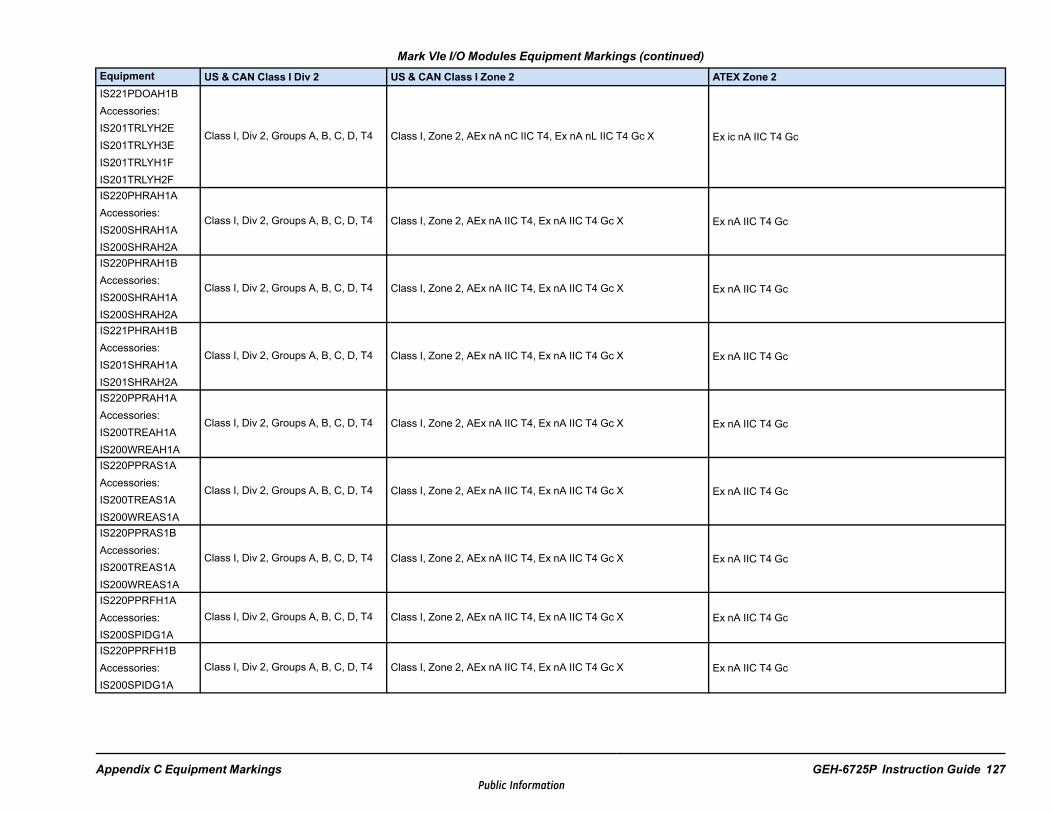
Mark VIe I/O Modules Equipment Markings (continued)Equipment US & CAN Class I Div 2 US & CAN Class I Zone 2 ATEX Zone 2IS221PDOAH1BAccessories:IS201TRLYH2EIS201TRLYH3EIS201TRLYH1FIS201TRLYH2F
Class I, Div 2, Groups A, B, C, D, T4 Class I, Zone 2, AEx nA nC IIC T4, Ex nA nL IIC T4 Gc X Ex ic nA IIC T4 Gc
IS220PHRAH1AAccessories:IS200SHRAH1AIS200SHRAH2A
Class I, Div 2, Groups A, B, C, D, T4 Class I, Zone 2, AEx nA IIC T4, Ex nA IIC T4 Gc X Ex nA IIC T4 Gc
IS220PHRAH1BAccessories:IS200SHRAH1AIS200SHRAH2A
Class I, Div 2, Groups A, B, C, D, T4 Class I, Zone 2, AEx nA IIC T4, Ex nA IIC T4 Gc X Ex nA IIC T4 Gc
IS221PHRAH1BAccessories:IS201SHRAH1AIS201SHRAH2A
Class I, Div 2, Groups A, B, C, D, T4 Class I, Zone 2, AEx nA IIC T4, Ex nA IIC T4 Gc X Ex nA IIC T4 Gc
IS220PPRAH1AAccessories:IS200TREAH1AIS200WREAH1A
Class I, Div 2, Groups A, B, C, D, T4 Class I, Zone 2, AEx nA IIC T4, Ex nA IIC T4 Gc X Ex nA IIC T4 Gc
IS220PPRAS1AAccessories:IS200TREAS1AIS200WREAS1A
Class I, Div 2, Groups A, B, C, D, T4 Class I, Zone 2, AEx nA IIC T4, Ex nA IIC T4 Gc X Ex nA IIC T4 Gc
IS220PPRAS1BAccessories:IS200TREAS1AIS200WREAS1A
Class I, Div 2, Groups A, B, C, D, T4 Class I, Zone 2, AEx nA IIC T4, Ex nA IIC T4 Gc X Ex nA IIC T4 Gc
IS220PPRFH1AAccessories:IS200SPIDG1A
Class I, Div 2, Groups A, B, C, D, T4 Class I, Zone 2, AEx nA IIC T4, Ex nA IIC T4 Gc X Ex nA IIC T4 Gc
IS220PPRFH1BAccessories:IS200SPIDG1A
Class I, Div 2, Groups A, B, C, D, T4 Class I, Zone 2, AEx nA IIC T4, Ex nA IIC T4 Gc X Ex nA IIC T4 Gc
Appendix C Equipment Markings GEH-6725P Instruction Guide 127Public Information

Mark VIe I/O Modules Equipment Markings (continued)Equipment US & CAN Class I Div 2 US & CAN Class I Zone 2 ATEX Zone 2IS220PPROH1AAccessories:IS200SPROH1AIS200SPROH2AIS200TPROH1CIS200TPROH2CIS200TREAH1AIS200TREAH3A
Class I, Div 2, Groups A, B, C, D, T4 Class I, Zone 2, AEx nA IIC T4, Ex nA IIC T4 Gc X Ex nA IIC T4 Gc
IS220PPROS1BAccessories:IS200SPROH1AIS200SPROH2AIS200TPROH1CIS200TPROH2CIS200TPROS1CIS200TPROS2CIS200TREAH1AIS200TREAH3A
Class I, Div 2, Groups A, B, C, D, T4 Class I, Zone 2, AEx nA IIC T4, Ex nA IIC T4 Gc X Ex nA IIC T4 Gc
IS220PRTDH1AAccessories:IS200TRTDH2DIS200SRTDH1AIS200SRTDH2A
Class I, Div 2, Groups A, B, C, D, T4 Class I, Zone 2, AEx nA [nC] IIC T4, Ex nA [nL] IIC T4 Gc X Ex nA [ic] IIC T4 Gc
IS220PRTDH1BAccessories:IS200TRTDH2DIS200SRTDH1AIS200SRTDH2A
Class I, Div 2, Groups A, B, C, D, T4 Class I, Zone 2, AEx nA [nC] IIC T4, Ex nA [nL] IIC T4 Gc X Ex nA [ic] IIC T4 Gc
IS221PRTDH1BAccessories:IS201TRTDH2DIS201SRTDH1AIS201SRTDH2A
Class I, Div 2, Groups A, B, C, D, T4 Class I, Zone 2, AEx nA [nC] IIC T4, Ex nA [nL] IIC T4 Gc X Ex nA [ic] IIC T4 Gc
128 GEH-6725P GEH-6725 Mark VIe and Mark VIeS Controls Equipment HazLocPublic Information

Mark VIe I/O Modules Equipment Markings (continued)Equipment US & CAN Class I Div 2 US & CAN Class I Zone 2 ATEX Zone 2IS220PSCAH1AAccessories:IS200SSCAH1AIS200SSCAH2A
Class I, Div 2, Groups A, B, C, D, T4 Class I, Zone 2, AEx nA IIC T4, Ex nA IIC T4 Gc X Ex nA IIC T4 Gc
IS220PSCAH1BAccessories:IS200SSCAH1AIS200SSCAH2A
Class I, Div 2, Groups A, B, C, D, T4 Class I, Zone 2, AEx nA IIC T4, Ex nA IIC T4 Gc X Ex nA IIC T4 Gc
IS221PSCAH1BAccessories:IS201SSCAH1AIS201SSCAH2A
Class I, Div 2, Groups A, B, C, D, T4 Class I, Zone 2, AEx nA IIC T4, Ex nA IIC T4 Gc X Ex nA IIC T4 Gc
IS42yPSCAH1BAccessories:IS40ySSCAH1AIS40ySSCAH2A
Class I, Div 2, Groups A, B, C, D, T4 Class I, Zone 2, AEx nA IIC T4, Ex nA IIC T4 Gc X Ex nA IIC T4 Gc
IS220PSVOH1AAccessories:IS200TSVCH2AIS210WSVOH1A
Class I, Div 2, Groups A, B, C, D, T4 Class I, Zone 2, AEx nA nC IIC T4, Ex nA nL IIC T4 Gc X Ex ic nA IIC T4 Gc
IS220PSVOH1BAccessories:IS200TSVCH2AIS210WSVOH1AIS410WSVOH1A
Class I, Div 2, Groups A, B, C, D, T4 Class I, Zone 2, AEx nA nC IIC T4, Ex nA nL IIC T4 Gc X Ex ic nA IIC T4 Gc
IS220PTCCH1AAccessories:IS200STTCH1AIS200STTCH2AIS200TBTCH1BIS200TBTCH1C
Class I, Div 2, Groups A, B, C, D, T4 Class I, Zone 2, AEx nA [nC] IIC T4, Ex nA [nL] IIC T4 Gc X Ex nA [ic] IIC T4 Gc
Appendix C Equipment Markings GEH-6725P Instruction Guide 129Public Information

Mark VIe I/O Modules Equipment Markings (continued)Equipment US & CAN Class I Div 2 US & CAN Class I Zone 2 ATEX Zone 2IS220PTCCH1BAccessories:IS200STTCH1AIS200STTCH2AIS200TBTCH1BIS200TBTCH1C
Class I, Div 2, Groups A, B, C, D, T4 Class I, Zone 2, AEx nA [nC] IIC T4, Ex nA [nL] IIC T4 Gc X Ex nA [ic] IIC T4 Gc
IS220PTURH1AAccessories:IS200TRPAH1A
Class I, Div 2, Groups A, B, C, D, T4 Class I, Zone 2, AEx nA IIC T4, Ex nA IIC T4 Gc X Ex nA IIC T4 Gc
IS220PTURH1BAccessories:IS200TRPAH1A
Class I, Div 2, Groups A, B, C, D, T4 Class I, Zone 2, AEx nA IIC T4, Ex nA IIC T4 Gc X Ex nA IIC T4 Gc
IS42yPUAAH1AAccessories:IS41ySUAAH1A
Class I, Div 2, Groups A, B, C, D, T4 Class I, Zone 2, AEx ic nA [ic] IIC T4, Ex ic nA [ic] IIC T4 Gc X Ex ic nA [ic] IIC T4 Gc
IS220PVIBH1AAccessories:IS200TVBAH2AIS200WNPSH1A
Class I, Div 2, Groups A, B, C, D, T4 Class I, Zone 2, AEx nA IIC T4, Ex nA IIC T4 Gc X Ex nA IIC T4 Gc
IS420PVIBH1BAccessories:IS200TVBAH2AIS40yTVBAH2BIS200WNPSH1AIS400WNPSH1A
Class I, Div 2, Groups A, B, C, D, T4 Class I, Zone 2, AEx nA IIC T4, Ex nA IIC T4 Gc X Ex nA IIC T4 Gc
130 GEH-6725P GEH-6725 Mark VIe and Mark VIeS Controls Equipment HazLocPublic Information

Mark VIeS Safety I/O ModulesMark VIeS Safety I/O Modules Equipment Markings
Equipment US & CAN Class I Div 2 US & CAN Class I Zone 2 ATEX Zone 2IS220YAICS1AAccessories:IS200STAIS1AIS400STAIS1AIS200STAIS2AIS400STAIS2AIS200TBAIS1CIS400TBAIS1C
Class I, Div 2, Groups A, B, C, D, T4 Class I, Zone 2, AEx nA nC [nC] IIC T4, Ex nA nL [nL] IIC T4 Gc X Ex ic nA [ic] IIC T4 Gc
ISx2yYAICS1BAccessories:ISx0ySTAIS1AISx0ySTAIS2AISx0yTBAIS1C
Class I, Div 2, Groups A, B, C, D, T4 Class I, Zone 2, AEx nA nC [nC] IIC T4, Ex nA nL [nL] IIC T4 Gc X Ex ic nA [ic] IIC T4 Gc
IS220YDIAS1AAccessories:IS200STCIS1AIS200STCIS2AIS200TBCIS2CIS400TBCIS2CIS400STCIS1AIS400STCIS2A
Class I, Div 2, Groups A, B, C, D, T4 Class I, Zone 2, AEx nA [nC] IIC T4, Ex nA [nL] IIC T4 Gc X Ex nA [ic] IIC T4 Gc
ISx2yYDIAS1BAccessories:ISx0ySTCIS1AISx0ySTCIS2AIS40ySTCIS4AISx0yTBCIS2CIS40yTBCIS3C
Class I, Div 2, Groups A, B, C, D, T4
When used with accessories ISx0ySTCIS1A, ISx0ySTCIS2A,ISx0yTBCIS2C: Class I, Zone 2, AEx nA [nC] IIC T4, Ex nA [nL] IIC T4Gc XWhen used with accessories IS40ySTCIS4A, IS40yTBCIS3C: Class I,Zone 2, AEx/Ex ec IIC T4 Gc X
When used with accessories ISx0ySTCIS1A,ISx0ySTCIS2A, ISx0yTBCIS2C: Ex ec [ic] IIC T4 GcWhen used with accessories IS40ySTCIS4A,IS40yTBCIS3C: Ex ec IIC T4 Gc
IS220YDOAS1AAccessories:IS200TRLYS1FIS200TRLYS2FIS400TRLYS1FIS400TRLYS2F
Class I, Div 2, Groups A, B, C, D, T4 Class I, Zone 2, AEx nA nC IIC T4, Ex nA nL IIC T4 Gc X Ex ic nA IIC T4 Gc
Appendix C Equipment Markings GEH-6725P Instruction Guide 131Public Information

Mark VIeS Safety I/O Modules Equipment Markings (continued)Equipment US & CAN Class I Div 2 US & CAN Class I Zone 2 ATEX Zone 2ISx2yYDOAS1BAccessories:IS40yTRLYS1BISx0yTRLYS1FISx0yTRLYS2FIS40yTRLYS1DIS40ySRLYS2AIS40yWROBH1AIS40yWROFH1AIS40yWROGH1A
Class I, Div 2, Groups A, B, C, D, T4
When used with accessories IS40yTRLYS1D, IS40yTRLYS1B,IS40yWROBH1A, IS40yWROFH1A, IS40yWROGH1A: Class I, Zone 2,AEx/Ex ic ec IIC T4 Gc X
When used with accessories ISx0yTRLYS1F, ISx0yTRLYS2F,IS40ySRLYS2A: Class I, Zone 2, AEx nA nC IIC T4, Ex nA nL IIC T4 Gc X
Ex ic ec IIC T4 Gc
IS220YHRAS1AAccessories:IS200SHRAS1AIS200SHRAS2A
Class I, Div 2, Groups A, B, C, D, T4 Class I, Zone 2, AEx nA IIC T4, Ex nA IIC T4 Gc X Ex nA IIC T4 Gc
IS220YPROS1AAccessories:IS200SPROS1AIS200TPROS1CIS200TPROS2CIS200TREAS1A
Class I, Div 2, Groups A, B, C, D, T4 Class I, Zone 2, AEx nA IIC T4, Ex nA IIC T4 Gc X Ex nA IIC T4 Gc
IS220YTCCS1AAccessories:IS200STTCS1AIS400STTCS1AIS200STTCS2AIS400STTCS2AIS200TBTCS1BIS200TBTCS1CIS400TBTCS1C
Class I, Div 2, Groups A, B, C, D, T4 Class I, Zone 2, AEx nA [nC] IIC T4, Ex nA [nL] IIC T4 Gc X Ex nA [ic] IIC T4 Gc
IS220YTURS1AAccessories:IS200TRPAS1A
Class I, Div 2, Groups A, B, C, D, T4 Class I, Zone 2, AEx nA IIC T4, Ex nA IIC T4 Gc X Ex nA IIC T4 Gc
IS42yYUAAS1AAccessories:IS41ySUAAS1A
Class I, Div 2, Groups A, B, C, D, T4 Class I, Zone 2, AEx ic nA [ic] IIC T4, Ex ic nA [ic] IIC T4 Gc X Ex ic nA [ic] IIC T4 Gc
132 GEH-6725P GEH-6725 Mark VIe and Mark VIeS Controls Equipment HazLocPublic Information

Mark VIeS Safety I/O Modules Equipment Markings (continued)Equipment US & CAN Class I Div 2 US & CAN Class I Zone 2 ATEX Zone 2IS220YVIBS1AAccessories:IS200TVBAS2AIS200WNPSS1A
Class I, Div 2, Groups A, B, C, D, T4 Class I, Zone 2, AEx nA IIC T4, Ex nA IIC T4 Gc X Ex nA IIC T4 Gc
IS42yYVIBS1BAccessories:ISx0yTVBAS2AIS40yTVBAS2BISx0yWNPSS1A
Class I, Div 2, Groups A, B, C, D, T4 Class I, Zone 2, AEx nA IIC T4, Ex nA IIC T4 Gc X Ex nA IIC T4 Gc
IS220YSILS1AAccessories:IS200TCSAS1AIS200WCSAS1AIS200SCSAS1A
Class I, Div 2, Groups A, B, C, D, T4 Class I, Zone 2, AEx nA nC IIC T4, Ex nA nL IIC T4 Gc X Ex ic nA IIC T4 Gc
IS220YSILS1BAccessories:IS200TCSAS1AIS200WCSAS1AIS200SCSAS1A
Class I, Div 2, Groups A, B, C, D, T4 Class I, Zone 2, AEx nA nC IIC T4, Ex nA nL IIC T4 Gc X Ex ic nA IIC T4 Gc
Appendix C Equipment Markings GEH-6725P Instruction Guide 133Public Information

Switches and ControllersSwitches and Controllers Equipment Markings
Equipment US & CAN Class I Div 2 US & CAN Class I Zone 2 ATEX Zone 2IS420ESWAH1AIS421ESWAH1AIS420ESWAH2AIS421ESWAH2AIS420ESWAH3AIS421ESWAH3AIS420ESWAH4AIS420ESWAH5AIS420ESWBH1AIS421ESWBH1AIS420ESWBH2AIS421ESWBH2AIS420ESWBH3AIS421ESWBH3AIS420ESWBH4AIS420ESWBH5A
Class I, Div 2, Groups A, B, C, D, T4 Class I, Zone 2, AEx nA IIC T4, Ex nA IIC T4 Gc X Ex nA IIC T4 Gc
IS220UCSAH1AIS420UCSBH1AIS421UCSBH1AIS420UCSBH3AIS420UCSBH4AIS421UCSBH4AIS420UCSBS1AIS421UCSBS1A
Class I, Div 2, Groups A, B, C, D, T4 Class I, Zone 2, AEx nA IIC T4, Ex nA IIC T4 Gc X Ex nA IIC T4 Gc
IS420UCSCH1IS420UCSCH2IS420UCSCS2
Class I, Div 2, Groups A, B, C, D, T4 Class I, Zone 2, AEx/Ex nA IIC T4 Gc Ex ec IIC T4 Gc
134 GEH-6725P GEH-6725 Mark VIe and Mark VIeS Controls Equipment HazLocPublic Information

Power DistributionPower Distribution Equipment Markings
Equipment US & CAN Class I Div 2 US & CAN Class I Zone 2 ATEX Zone 2IS210JPDHG1AIS410JPDHG1AIS411JPDHG1A
Class I, Div 2, Groups A, B, C, D, T4 Class I, Zone 2, AEx nA IIC T4, Ex nA IIC T4 Gc X Ex nA IIC T4 Gc
IS220PPDAH1AAccessories:IS200JPDSG1A
Class I, Div 2, Groups A, B, C, D, T4 Class I, Zone 2, AEx nA IIC T4, Ex nA IIC T4 Gc X Ex nA IIC T4 Gc
ISx2yPPDAH1BAccessories:ISx0yJPDSG1AIS40yJPDGH1A
Class I, Div 2, Groups A, B, C, D, T4
When used with accessories IS40yJPDGH1A: Class I, Zone2, AEx/Ex ec IIC T4 Gc XWhen used with accessories ISx0yJPDSG1A: Class I, Zone2, AEx nA IIC T4, Ex nA IIC T4 Gc X
Ex ec IIC T4 Gc
IS41yJPDDG1AIS41yJPDDG2AIS41yJPDDG3AIS41yJPDDG4A
Class I, Div 2, Groups A, B, C, D, T3A Class I, Zone 2, AEx/Ex ec IIC T3 Gc X Ex ec IIC T3 Gc
IS41yJPDEG1A Class I, Div 2, Groups A, B, C, D, T4 Class I, Zone 2, AEx/Ex ec IIC T4 Gc X Ex ec IIC T4 Gc
Appendix C Equipment Markings GEH-6725P Instruction Guide 135Public Information

Notes
136 GEH-6725P GEH-6725 Mark VIe and Mark VIeS Controls Equipment HazLocPublic Information

Appendix D Ambient TemperatureRatings
Note In the following tables, y = 0 or 1 for module part numbers.
Ambient Temperature Ratings
GE Part Number Ambient Temperature RatingIS200JPDLG1A
-30 to + 65°C (-22 to +149 °F)
IS210BAPAH1AIS220PAICH1AIS220PAOCH1BIS220PCLAH1AIS220PCLAH1BIS220PDIAH1AIS220PDIIH1BIS220PDIOH1AIS220PDIOH1BIS220PDOAH1AIS220PHRAH1AIS220PHRAH1BIS220PPDAH1AIS220PPRAH1AIS220PPRAS1AIS220PPRAS1BIS220PPROH1AIS220PPROS1BIS220PRTDH1AIS220PRTDH1BIS220PSCAH1AIS220PSCAH1BIS220PSCHH1AIS220PSVOH1AIS220PSVOH1BIS220PTCCH1AIS220PTCCH1BIS220PTURH1AIS220PTURH1BIS220PVIBH1AIS220YAICS1AIS220YDIAS1AIS220YDOAS1AIS220YHRAS1AIS220YPROS1AIS220YSILS1AIS220YSILS1BIS220YTCCS1AIS220YTURS1AIS220YVIBS1AIS221PHRAH1B
Appendix D Ambient Temperature Ratings GEH-6725P Instruction Guide 137Public Information

Ambient Temperature Ratings (continued)
GE Part Number Ambient Temperature RatingIS221PRTDH1B
-30 to + 65°C (-22 to +149 °F)
IS221PSCAH1BIS420PPNGH1AIS420UCSBH1AIS420UCSBH4AIS420UCSBS1AIS421UCSBH1AIS421UCSBH4AIS421UCSBS1A
IS220PCNOH1A
-20 to +55°C (-4 to +131 °F)IS220PCNOH1BIS220PPRFH1AIS220PPRFH1B
IS220UCSAH1A 0 to 65°C (32 to 149 °F)IS420UCSBH3A
IS41yBAPBH1A
-40 to +70°C (-40 to 158 °F)
IS41yJPDDG1AIS41yJPDDG2AIS41yJPDDG3AIS41yJPDDG4AIS41yJPDEG1AIS210JPDHG1AIS400JPDHG1AIS410JPDHG1AIS411JPDHG1AISx2yPAICH1BISx2yPDIAH1BISx2yPDOAH1BISx2yPPDAH1BIS42yPSCAH1BIS42yPVIBH1BIS42yPUAAH1AISx2yYAICS1BISx2yYDIAS1BISx2yYDOAS1BIS42yYUAAS1AIS42yYVIBS1BIS42yESWAH1AIS42yESWAH2AIS42yESWAH3AIS42yESWAH4AIS42yESWAH5AIS42yESWBH1AIS42yESWBH2AIS42yESWBH3A
138 GEH-6725P GEH-6725 Mark VIe and Mark VIeS Controls Equipment HazLocPublic Information
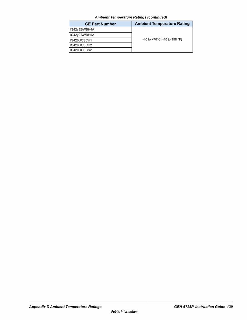
Ambient Temperature Ratings (continued)
GE Part Number Ambient Temperature RatingIS42yESWBH4A
-40 to +70°C (-40 to 158 °F)IS42yESWBH5AIS420UCSCH1IS420UCSCH2IS420UCSCS2
Appendix D Ambient Temperature Ratings GEH-6725P Instruction Guide 139Public Information

Notes
140 GEH-6725P GEH-6725 Mark VIe and Mark VIeS Controls Equipment HazLocPublic Information


Public Information