gemini 8m telescope enclosure design … revision 2 gemini 8m telescope enclosure design...
TRANSCRIPT

SPE-TE-G0012Revision 2
Gemini 8m Telescope Enclosure DesignRequirements Document
Telescope Structure, Building, and Enclosure Group
15 October 1993
GEMINI PROJECT OFFICE 950 N. Cherry Ave. Tucson, Arizona 85719Phone: (520) 318-8545 Fax: (520) 318-8590

Table of Contents
Section 1 GENERAL REQUIREMENTS . . . . . . . . . . . . . . . . . . . . . . . . . . . . . . . . . . . . . . . . . . . 1. . . . . . .
1.1 Scope of This Document . . . . . . . . . . . . . . . . . . . . . . . . . . . . . . . . . . . . . . . . . . . . . . . . . . . . . . . . 1. . . . . . .
1.2 Related Gemini 8M Telescopes Project Documents . . . . . . . . . . . . . . . . . . . . . . . . . . . . . . 1. . . . . . .
1.3 Definition of Key Terms and Abbreviations . . . . . . . . . . . . . . . . . . . . . . . . . . . . . . . . . . . . . 1. . . . . . .
1.3.1 General Definitions . . . . . . . . . . . . . . . . . . . . . . . . . . . . . . . . . . . . . . . . . . . . . . . . . . . . . . . . . . . 1. . . . . . .
1.3.2 Facility and Technical Definitions . . . . . . . . . . . . . . . . . . . . . . . . . . . . . . . . . . . . . . . . . . . . . 2. . . . . . .
1.3.3 Organization and Code Abbreviations . . . . . . . . . . . . . . . . . . . . . . . . . . . . . . . . . . . . . . . . . 3. . . . . . .
1.4 Applicable Codes and Requirements . . . . . . . . . . . . . . . . . . . . . . . . . . . . . . . . . . . . . . . . . . . . . 4. . . . . . .
1.5 Standards and Manufacturer’s Instructions . . . . . . . . . . . . . . . . . . . . . . . . . . . . . . . . . . . . . . . 4. . . . . . .
1.6 Useful Life of the Facility . . . . . . . . . . . . . . . . . . . . . . . . . . . . . . . . . . . . . . . . . . . . . . . . . . . . . . . 5. . . . . . .
Section 2 ENVIRONMENTAL CONDITIONS . . . . . . . . . . . . . . . . . . . . . . . . . . . . . . . . . . . . . . 6. . . . . . .
2.1 Design Approach for the Gemini Enclosure Carousel . . . . . . . . . . . . . . . . . . . . . . . . . . . . 6. . . . . . .
2.2 Observing Conditions . . . . . . . . . . . . . . . . . . . . . . . . . . . . . . . . . . . . . . . . . . . . . . . . . . . . . . . . . . . 6. . . . . . .
2.2.1 Mauna Kea . . . . . . . . . . . . . . . . . . . . . . . . . . . . . . . . . . . . . . . . . . . . . . . . . . . . . . . . . . . . . . . . . . . . 7. . . . . . .
2.2.2 Cerro Pachon . . . . . . . . . . . . . . . . . . . . . . . . . . . . . . . . . . . . . . . . . . . . . . . . . . . . . . . . . . . . . . . . . . 7. . . . . . .
2.3 Survival Conditions . . . . . . . . . . . . . . . . . . . . . . . . . . . . . . . . . . . . . . . . . . . . . . . . . . . . . . . . . . . . . 7. . . . . . .
2.3.1 Mauna Kea . . . . . . . . . . . . . . . . . . . . . . . . . . . . . . . . . . . . . . . . . . . . . . . . . . . . . . . . . . . . . . . . . . . . 8. . . . . . .
2.3.2 Cerro Pachon . . . . . . . . . . . . . . . . . . . . . . . . . . . . . . . . . . . . . . . . . . . . . . . . . . . . . . . . . . . . . . . . . . 9. . . . . . .
Section 3 ENCLOSURE CAROUSEL DESIGN REQUIREMENTS . . . . . . . . . . . . . . . . . 10. . . . . .
3.1 General Description . . . . . . . . . . . . . . . . . . . . . . . . . . . . . . . . . . . . . . . . . . . . . . . . . . . . . . . . . . . . . 10. . . . . .
3.2 Enclosure Carousel Motion and Swept Volume Requirements . . . . . . . . . . . . . . . . . . . 10. . . . . .
3.2.1 Telescope Swept Volume . . . . . . . . . . . . . . . . . . . . . . . . . . . . . . . . . . . . . . . . . . . . . . . . . . . . . . 11. . . . . .
3.2.2 Enclosure Azimuth Motion . . . . . . . . . . . . . . . . . . . . . . . . . . . . . . . . . . . . . . . . . . . . . . . . . . . . 11. . . . . .
3.2.3 Viewing Aperture . . . . . . . . . . . . . . . . . . . . . . . . . . . . . . . . . . . . . . . . . . . . . . . . . . . . . . . . . . . . . 11. . . . . .
3.2.4 Shutter and Wind Blind System . . . . . . . . . . . . . . . . . . . . . . . . . . . . . . . . . . . . . . . . . . . . . . . 12. . . . . .
3.3 Enclosure Azimuth Track . . . . . . . . . . . . . . . . . . . . . . . . . . . . . . . . . . . . . . . . . . . . . . . . . . . . . . . 12. . . . . .
3.3.1 Track Interface with the Enclosure Base . . . . . . . . . . . . . . . . . . . . . . . . . . . . . . . . . . . . . . . 13. . . . . .
Gemini 8M Telescope Enclosure DesignRequirements Document SPE-TE-G0012
Revision 2 i 15 October 1993
3.4 Enclosure Carousel Azimuth Bogie System . . . . . . . . . . . . . . . . . . . . . . . . . . . . . . . . . . . . . . 13. . . . . .
3.4.1 Bogie Wheels . . . . . . . . . . . . . . . . . . . . . . . . . . . . . . . . . . . . . . . . . . . . . . . . . . . . . . . . . . . . . . . . . 14. . . . . .
3.4.2 Lateral Restraint Rollers and Overturning Holddowns . . . . . . . . . . . . . . . . . . . . . . . . . . 14. . . . . .
3.4.3 Bogie Drives . . . . . . . . . . . . . . . . . . . . . . . . . . . . . . . . . . . . . . . . . . . . . . . . . . . . . . . . . . . . . . . . . . 14. . . . . .
3.4.4 Rotational Positioning Control System . . . . . . . . . . . . . . . . . . . . . . . . . . . . . . . . . . . . . . . . . 15. . . . . .
3.5 Viewing Aperture Shutter System and Wind Blind System . . . . . . . . . . . . . . . . . . . . . . . 15. . . . . .
3.5.1 Shutter System and Operation . . . . . . . . . . . . . . . . . . . . . . . . . . . . . . . . . . . . . . . . . . . . . . . . . 15. . . . . .
3.5.2 Wind Blind System and Operation . . . . . . . . . . . . . . . . . . . . . . . . . . . . . . . . . . . . . . . . . . . . . 16. . . . . .
3.5.3 Viewing Aperture Shutter Positioning Control System . . . . . . . . . . . . . . . . . . . . . . . . . 16. . . . . .
3.6 Exterior Ventilation Gate System . . . . . . . . . . . . . . . . . . . . . . . . . . . . . . . . . . . . . . . . . . . . . . . . 17. . . . . .
3.6.1 Ventilation Gate Operation . . . . . . . . . . . . . . . . . . . . . . . . . . . . . . . . . . . . . . . . . . . . . . . . . . . . 17. . . . . .
3.6.2 Ventilation Gate Positioning Control System . . . . . . . . . . . . . . . . . . . . . . . . . . . . . . . . . . 18. . . . . .
3.7 Carousel Passive Ventilation Openings . . . . . . . . . . . . . . . . . . . . . . . . . . . . . . . . . . . . . . . . . . 18. . . . . .
3.8 Ventilation of the Carousel Shell . . . . . . . . . . . . . . . . . . . . . . . . . . . . . . . . . . . . . . . . . . . . . . . . 18. . . . . .
3.8.1 Passive Ventilation . . . . . . . . . . . . . . . . . . . . . . . . . . . . . . . . . . . . . . . . . . . . . . . . . . . . . . . . . . . . 19. . . . . .
3.8.2 Active Ventilation . . . . . . . . . . . . . . . . . . . . . . . . . . . . . . . . . . . . . . . . . . . . . . . . . . . . . . . . . . . . . 19. . . . . .
3.9 Carousel Exterior Surface Coatings . . . . . . . . . . . . . . . . . . . . . . . . . . . . . . . . . . . . . . . . . . . . . . 19. . . . . .
3.10 Shutter Crane . . . . . . . . . . . . . . . . . . . . . . . . . . . . . . . . . . . . . . . . . . . . . . . . . . . . . . . . . . . . . . . . . . 19. . . . . .
3.10.1 Interface With the Coating Chamber Room Lifting Shaft . . . . . . . . . . . . . . . . . . . . . 20. . . . . .
3.10.2 Shutter Crane Operation . . . . . . . . . . . . . . . . . . . . . . . . . . . . . . . . . . . . . . . . . . . . . . . . . . . . . . 20. . . . . .
3.10.3 Shutter Crane Controls . . . . . . . . . . . . . . . . . . . . . . . . . . . . . . . . . . . . . . . . . . . . . . . . . . . . . . . 20. . . . . .
3.11 Permanent Arch Girder Lifting Lugs . . . . . . . . . . . . . . . . . . . . . . . . . . . . . . . . . . . . . . . . . . . 21. . . . . .
3.12 Carousel Electrical Systems . . . . . . . . . . . . . . . . . . . . . . . . . . . . . . . . . . . . . . . . . . . . . . . . . . . . 21. . . . . .
3.12.1 Electrical Power and Data Transmission . . . . . . . . . . . . . . . . . . . . . . . . . . . . . . . . . . . . . . 21. . . . . .
3.12.2 Grounding . . . . . . . . . . . . . . . . . . . . . . . . . . . . . . . . . . . . . . . . . . . . . . . . . . . . . . . . . . . . . . . . . . . 22. . . . . .
3.12.3 Lightning Protection . . . . . . . . . . . . . . . . . . . . . . . . . . . . . . . . . . . . . . . . . . . . . . . . . . . . . . . . . 22. . . . . .
3.12.4 Lighting . . . . . . . . . . . . . . . . . . . . . . . . . . . . . . . . . . . . . . . . . . . . . . . . . . . . . . . . . . . . . . . . . . . . . 22. . . . . .
3.13 Carousel Control Panel . . . . . . . . . . . . . . . . . . . . . . . . . . . . . . . . . . . . . . . . . . . . . . . . . . . . . . . . . 22. . . . . .
3.13.1 Carousel Azimuth Motion . . . . . . . . . . . . . . . . . . . . . . . . . . . . . . . . . . . . . . . . . . . . . . . . . . . . 23. . . . . .
3.13.2 Upper Shutter Motion . . . . . . . . . . . . . . . . . . . . . . . . . . . . . . . . . . . . . . . . . . . . . . . . . . . . . . . . 23. . . . . .
3.13.3 Lower Shutter Motion . . . . . . . . . . . . . . . . . . . . . . . . . . . . . . . . . . . . . . . . . . . . . . . . . . . . . . . . 23. . . . . .
3.13.4 Ventilation Gate No. 1 Motion . . . . . . . . . . . . . . . . . . . . . . . . . . . . . . . . . . . . . . . . . . . . . . . 24. . . . . .
3.14.5 Ventilation Gate No. 2 Motion . . . . . . . . . . . . . . . . . . . . . . . . . . . . . . . . . . . . . . . . . . . . . . . 24. . . . . .
3.15 Carousel Radio Remote Control . . . . . . . . . . . . . . . . . . . . . . . . . . . . . . . . . . . . . . . . . . . . . . . . 24. . . . . .
Gemini 8M Telescope Enclosure DesignRequirements Document SPE-TE-G0012
Revision 2 ii 15 October 1993

3.16 Carousel Emergency Stops . . . . . . . . . . . . . . . . . . . . . . . . . . . . . . . . . . . . . . . . . . . . . . . . . . . . . 25. . . . . .
3.17 Controls Interface . . . . . . . . . . . . . . . . . . . . . . . . . . . . . . . . . . . . . . . . . . . . . . . . . . . . . . . . . . . . . . 25. . . . . .
3.17.1 Control Philosophy . . . . . . . . . . . . . . . . . . . . . . . . . . . . . . . . . . . . . . . . . . . . . . . . . . . . . . . . . . . 25. . . . . .
3.17.2 Transport and Protocol Level Interface . . . . . . . . . . . . . . . . . . . . . . . . . . . . . . . . . . . . . . . 26. . . . . .
3.17.3 Command Level Interface . . . . . . . . . . . . . . . . . . . . . . . . . . . . . . . . . . . . . . . . . . . . . . . . . . . . 26. . . . . .
3.17.4 Testing of AURA - Coast Control Interface . . . . . . . . . . . . . . . . . . . . . . . . . . . . . . . . . . . 27. . . . . .
3.18 Instrumentation Flat Field . . . . . . . . . . . . . . . . . . . . . . . . . . . . . . . . . . . . . . . . . . . . . . . . . . . . . . 27. . . . . .
3.19 Interior Surface Finishes . . . . . . . . . . . . . . . . . . . . . . . . . . . . . . . . . . . . . . . . . . . . . . . . . . . . . . . 27. . . . . .
3.20 Enclosure Platform Lift . . . . . . . . . . . . . . . . . . . . . . . . . . . . . . . . . . . . . . . . . . . . . . . . . . . . . . . . 27. . . . . .
3.21 Interior Surface Finishes . . . . . . . . . . . . . . . . . . . . . . . . . . . . . . . . . . . . . . . . . . . . . . . . . . . . . . . 29. . . . . .
Section 4 CAROUSEL OPERATION . . . . . . . . . . . . . . . . . . . . . . . . . . . . . . . . . . . . . . . . . . . . . . . 30. . . . . .
4.1 Telescope Observing Conditions . . . . . . . . . . . . . . . . . . . . . . . . . . . . . . . . . . . . . . . . . . . . . . . . 30. . . . . .
Section 5 INSTALLATION ACCEPTANCE TESTING . . . . . . . . . . . . . . . . . . . . . . . . . . . . . 31. . . . . .
Gemini 8M Telescope Enclosure DesignRequirements Document SPE-TE-G0012
Revision 2 iii 15 October 1993
List of Figures
Figure 2-1 Sublease Plan (Mauna Kea Site)Figure 2-2 Enclosure/Support Facility Plan (Mauna Kea Site)Figure 2-3 Cerro Pachon (Site Overview)Figure 2-4 Cerro Pachon (Gemini Site)Figure 3-1 Telescope/Enclosure ClearanceFigure 3-2 Enclosure OverviewFigure 3-3 Telescope/Enclosure Safe ZoneFigure 3-4 Viewing Aperture/Shutter & Windscreen DetailFigure 3-5 Carousel Track TolerancesFigure 3-6 Enclosure (Inspection Gantry)Figure 3-7 Bi-parting Ventilation GatesFigure 3-8 Daytime Ambient Air flow Regime (Passive)Figure 3-9 5th Percentile Nighttime Ambient Flow Regime (Active)Figure 3-10 Enclosure CraneFigure 3-11 Enclosure Communication PlanFigure 3-12 Possible Flat Field Source PositionFigure 3-13 Observing Floor/Platform Lift I/FFigure 3-14 Primary Mirror HandlingFigure 3-15 Primary Mirror CartFigure 3-16 Top End HandlingFigure 3-17 Top End Cart (F/16)
Gemini 8M Telescope Enclosure DesignRequirements Document SPE-TE-G0012
Revision 2 iv 15 October 1993
Section 1
GENERAL REQUIREMENTS
1.1 Scope of This Document
(a) This document consists of the functional design requirements specification for theGemini enclosure carousel and an enclosure platform lift. CCC shall provide for all therequirements in this document unless indicated specifically by N.I.C. (not in contract).
(b) This document does not specifically address any of the design requirements for theGemini telescope, the telescope pier, the enclosure base, the foundation system for the telescopepier and enclosure, the interior of the enclosure base, the Gemini positioning control system, thesupport facility, or any site work. Information on these topics can be obtained from one of thereferenced documents listed in Section 1.2.
1.2 Related Gemini 8M Telescopes Project Documents
Information on other selected areas of the project can be found in the following documents. Amore complete listing can be obtained from the Project Office.
SPE-C-G0010 Positioning Control System Design Requirements.SPE-C-G0022 Gemini Enclosure Control System Overview.SPE-TE-G0002 Gemini 8M Telescope Design Requirements Document.SPE-TE-G0013 Gemini 8M Telescope Enclosure Base, Support
Facility and Site Work Design Requirements Document.ICDG0004 Gemini Enclosure Interface Control Document. 1.3 Definition Of Key Terms and Abbreviations
The following key terms and abbreviations are used throughout this document. Their specificmeaning in the context of this document are defined in the following.
1.3.1 General Definitions
Construction Drawings - The drawings prepared by CCC and approved by AURA for use in the construction of the Work.Construction Specifications - The specifications prepared by CCC and approved by AURA
for use in the construction of the Work.Contract Documents - The sum of the Design and Construction Contract, the Design
Requirements Document, the Interface Control Document, and all Modifications issued after execution of the Contract. A Modification, or Change Order, is a written amendment to the Contract signed by both parties.
Design Requirements Document - The provisions contained within this document.
Gemini 8M Telescope Enclosure DesignRequirements Document SPE-TE-G0012
Revision 2 1 15 October 1993
Furnish - CCC shall supply and deliver to the Project site, unloaded, unpacked, and assembled ready for the intended use or installation, as applicable in each instance.
Install - CCC shall construct, erect, or set in place for the intended use and includes to finish and to clean, as applicable in each instance.
N.I.C. - Not in contract.Project - The total design and construction of the two Gemini 8m Telescopes facilities.Provide - CCC shall furnish and install, complete and ready for intended use, as applicable in
each instance.Work - The completed design and construction required by the Contract Documents and
includes all materials and equipment incorporated or to be incorporated in theconstruction and all labor necessary to produce such construction.
1.3.2 Facility and Technical Definitions
Air Exhaust Tunnel - The tunnel approximately 3 meters in diameter used to convey heated facility air away from the Gemini telescope optical path.
Altitude Angle - The vertical angle measured in degrees from the horizontal. The zero reference is at the horizon with positive values toward the zenith.
Azimuth Angle - The horizontal angle measured in degrees. The zero reference point is toward the south. The positive rotation vector is toward nadir (opposite to zenith).
CCP - Carousel control panel.Coating Chamber Room Lifting Shaft (N.I.C.) - The connecting device that extends the
lifting capability of the shutter crane into the Coating Chamber Room (located within the enclosure base) during primary mirror handling.
ECSWPR - Enclosure control system work package responsible.Enclosure Base - The stationary portion of the enclosure, including the stationary chamber
floor, but not including the platform lift. The interior space is utilized primarily for the mirror recoating process and for telescope top end storage and maintenance.
Enclosure Carousel - The rotating portion of the enclosure located above the top floor surface of the enclosure base.
Platform Lift - The large capacity, vertically moving floor platform which travels between the lower level of the enclosure and the telescope chamber.
Rotating Telescope Floor - The circular-disk floor connected to and supported by the telescope mount.
Shutters - The two-part robust moving door system that opens or closes the viewing aperture and provides telescope wind protection.
Shutter Crane - The 40 metric tonne hoist device located within the structure of the upper shutter.
Spring Line - The horizontal equator of the spherical shape comprising the enclosure carousel.
Stationary Chamber Floor - The floor that surrounds the rotating telescope floor, which is connected to and supported by the enclosure base perimeter structure.
Support Facility - The building adjacent to the enclosure which houses the main support functions of telescope operations, telescope instrument assembly and disassembly,
optomechanics and array/electronics labs, and the mechanical plant room.
Gemini 8M Telescope Enclosure DesignRequirements Document SPE-TE-G0012
Revision 2 2 15 October 1993

Telescope Pier - The concrete single wall cylinder, not including the azimuth track anchor bolts, which support the telescope azimuth track.
Tracking - The motion of the telescope necessary to follow a star in tis apparent motion across the sky.
Ventilation Gate - The robust, vertically bi-parting exterior door system located around the perimeter of the carousel. When opened, the system exposes the passive ventilation openings.
Wind Blind - The moveable perforated panels located within the carousel viewing aperture that provide telescope wind protection. The fixed wind blind is located between arch girders below the lowest portion of the viewing aperture.
Wind Screen (N.I.C.) - The system located within the carousel perimeter passive ventilation openings that provide controlled attenuation of air flow across the telescope chamber.
Zenith - The point located directly above the observer (altitude angle = 90o).
1.3.3 Organization and Code Abbreviations
CCC may use the following organization and code abbreviations within the ConstructionDocuments. References to other organizations and codes shall be by complete spelling of thenames.
AA Aluminum AssociationAAMA Architectural Aluminum Manufacturers’ AssociationACI American Concrete InstituteAISC American Institute of Steel Construction, Inc.AISI American Iron and Steel InstituteAPA American Plywood AssociationASCE American Society of Civil EngineersASHRAE American Society of Heating, Refrigerating and Air Conditioning Engineers, Inc.ASTM American Society for Testing and MaterialsAWS American Welding Society, Inc.CRSI Concrete Reinforcing Steel InstituteCS Commercial Standard, US Department of CommerceFS Federal Specification of General Services AdministrationMIL Military Specification of U.S. Department of DefenseNAAMM The National Association of Architectural Metal ManufacturersNEC National Electric CodeNEMA National Electrical Manufacturers’ AssociationNFPA National Fire Protection AssociationPS Product Standard of National Bureau of StandardsSMACNA Sheet Metal and Air Conditioning Contractors’ National Association, Inc.SSPC Steel Structures Painting CouncilUBC Uniform Building CodeUL Underwriters’ Laboratories, Inc.
Gemini 8M Telescope Enclosure DesignRequirements Document SPE-TE-G0012
Revision 2 3 15 October 1993

1.4 Applicable Codes and Requirements
(a) The following codes and regulations shall form the basis of compliance for design andconstruction, and the current edition utilized by the local building officials shall be used. Inaddition to the codes and regulations, CCC shall become familiar with the requirements of theGemini Electronic Design Specification listed below in the execution of the Work under thisContract.
Uniform Building Code.Uniform Mechanical Code.Uniform Plumbing Code.Uniform Fire Code.National Electrical Code.ASCE 7-88 (for wind load and load combination determination)."Recommended Lateral Force Requirements and Commentary," Seismology Committee ofthe Structural Engineers Association of California.OSHA Health Regulations.Americans with Disabilities Act of 1990.Hawaii Department of Health - Air Pollution Ordinance.SPE-ASA-G0008 - Gemini Electronic Design Specification.Other applicable codes and requirements with specific application to the Mauna Kea, Hawaii,USA site and the Cerro Pachon, Chile site.
(b) Where discrepancies exist between the requirements of the various codes, therequirements that offer the greatest protection to the Owner will govern.
1.5 Standards and Manufacturer’s Instructions
(a) Any material specified by reference to the number, symbol, or title of a specificstandard in the Construction Specifications shall be U.S. Standards such as a CommercialStandard, Federal Specifications, American Society for Testing Materials, a trade associationstandard, or other similar standard. CCC shall submit copies of the standards referenced whenrequested by AURA.
(b) Where the Construction Specifications require materials, products, processes,equipment, or the like to be installed or applied in accordance with manufacturer’s instructions,directions, or specifications or words to this effect, they shall be construed to mean that saidapplication by the manufacturer of the material concerned is for use under conditions similar tothose at the jobsite.
(c) Copies of such instructions shall be submitted to AURA for review before work isbegun.
Gemini 8M Telescope Enclosure DesignRequirements Document SPE-TE-G0012
Revision 2 4 15 October 1993
1.6 Useful Life of the Facility
The useful lifetime of the facility is likely to exceed 50 years. Therefore, due consideration offatigue shall be given to all structural members and connections subjected to stress fluctuations,and components shall be designed for 50 years of use. Any component not designed for 50 yearsof use shall be identified by CCC, and its application requires prior approval by AURA.
Gemini 8M Telescope Enclosure DesignRequirements Document SPE-TE-G0012
Revision 2 5 15 October 1993

Section 2
ENVIRONMENTAL CONDITIONS
2.1 Design Approach for the Gemini Enclosure Carousel
(a) The Gemini Project will build two telescope facilities: one on Mauna Kea on theisland of Hawaii, U.S.A. and the other on Cerro Pachon in Chile. The site elevations for MaunaKea and Cerro Pachon are 4,194 m (13,760 ft) and 2,715 m (8,907 ft) respectively. For bothsites, the footprint of the support facility (N.I.C.) and exhaust tunnel (N.I.C.) will be in place, andthe enclosure base structure (N.I.C.) will be complete, when enclosure carousel constructioncommences. However, construction by others will be proceeding concurrently within the supportfacility during carousel erection.
(b) The Mauna Kea Gemini site is located on the summit ridge between the UH 88-inchfacility and the CFHT facility. Figure 2-1 shows the Mauna Kea site and indicates the localtopography and the sublease boundary. Figure 2-2 shows the detail of the Gemini facility forreference.
(c) The Cerro Pachon Gemini site is located approximately 70 straight-line kilometerseast of the Chilean coastal town of La Serena, and approximately 10 straight-line kilometerssoutheast of the Cerro Tololo Inter-American Observatory (CTIO). Figure 2-3 illustrates thetopography surrounding the Gemini site, and Figure 2-4 depicts the local site details for theGemini facility.
(d) For economy and with no loss in performance, an identical enclosure will be used forboth sites. Thus, CCC shall review the environmental conditions information for both sites anddesign the enclosure utilizing the more stringent of the two site requirements.
2.2 Observing Conditions
(a) The following data represent the range of occurring environmental conditions whilethe Gemini facility will be in use. The enclosure carousel, azimuth track/bogie system, shutters,ventilation gates, and wind blinds shall remain fully operational throughout the range ofconditions indicated. The depression temperature shall apply locally to all exterior cladding,structural steel, and mechanisms that are directly exposed to the nighttime sky. The depressiontemperature specified is the temperature to which an exposed object will cool through radiationto the nighttime sky.
(b) Dead loads, live loads, ice and/or snow loads, temperature effects, and wind orseismic loads shall be combined per the ASCE 7-88 Standard when determining the critical casefor stresses and deflections.
Gemini 8M Telescope Enclosure DesignRequirements Document SPE-TE-G0012
Revision 2 6 15 October 1993

2.2.1 Mauna Kea
Operating wind speeds: Up to 35 m/sec (78 mph) from any direction for the ventilation gates and azimuth bogie operation. Up to 30 m/sec (67 mph) from any direction for the remaining systems.
Operating temperature range: -15oC to +20oC (+5oF to 68oF). Operating humidity range: 5% to 90%.
Air pressure range: 600 mb to 700 mb.
Depression temperature: -25oC (-13oF).
Max uniform ice build-up: 25 mm (1.0 in) or 22 kg/m2 (4.7 psf).
Shutter Crane Usage: See Section 3.10.
2.2.2 Cerro Pachon
Operating wind speeds: Up to 35 m/sec (78 mph) from any direction for the ventilation gates and azimuth bogie operation. Up to 30 m/sec (67 mph) from any direction for the remaining systems.
.Operating temperature range: -15oC to +25oC (+5oF to 77oF).
Operating humidity range: 5% to 95%.
Air pressure range: 700 mb to 800 mb.
Depression temperature: -25oC (-13oF).
Max uniform ice build-up: 25 mm (1.0 in) or 22 kg/m2 (4.7 psf).
Shutter Crane Usage: See Section 3.10.
2.3 Survival Conditions
(a) The following data represent the extreme environmental conditions the enclosurecarousel must be able to withstand. The enclosure carousel and enclosure base shall be in thefully-closed configuration when considering wind load and icing effects. The snow loading and
Gemini 8M Telescope Enclosure DesignRequirements Document SPE-TE-G0012
Revision 2 7 15 October 1993
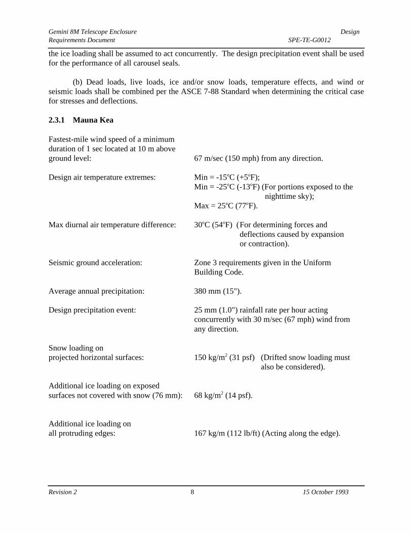
the ice loading shall be assumed to act concurrently. The design precipitation event shall be usedfor the performance of all carousel seals.
(b) Dead loads, live loads, ice and/or snow loads, temperature effects, and wind orseismic loads shall be combined per the ASCE 7-88 Standard when determining the critical casefor stresses and deflections.
2.3.1 Mauna Kea
Fastest-mile wind speed of a minimumduration of 1 sec located at 10 m aboveground level: 67 m/sec (150 mph) from any direction.
Design air temperature extremes: Min = -15oC (+5oF);Min = -25oC (-13oF) (For portions exposed to the
nighttime sky);Max = 25oC (77oF).
Max diurnal air temperature difference: 30oC (54oF) (For determining forces and deflections caused by expansion or contraction).
Seismic ground acceleration: Zone 3 requirements given in the Uniform Building Code.
Average annual precipitation: 380 mm (15").
Design precipitation event: 25 mm (1.0") rainfall rate per hour acting concurrently with 30 m/sec (67 mph) wind fromany direction.
Snow loading on projected horizontal surfaces: 150 kg/m2 (31 psf) (Drifted snow loading must
also be considered).
Additional ice loading on exposed surfaces not covered with snow (76 mm): 68 kg/m2 (14 psf).
Additional ice loading on all protruding edges: 167 kg/m (112 lb/ft) (Acting along the edge).
Gemini 8M Telescope Enclosure DesignRequirements Document SPE-TE-G0012
Revision 2 8 15 October 1993

2.3.2 Cerro Pachon
Fastest-mile wind speed of a minimumduration of 1 sec located at 10 m aboveground level: 54 m/sec (120 mph) from any direction.
Design air temperature extremes: Min = -15oC (+5oF);Min = -25oC (-13oF) (For portions exposed to
the nighttime sky);Max = 30oC (86oF).
Max diurnal air temperature difference: 30oC (54oF) (For determining forces and deflections caused by expansion or contraction).
Seismic ground acceleration: Zone 4 requirements given in the Uniform Building Code.
Range of annual precipitation1: 11.4 mm to 487mm (0.45" to 19.2").
Design precipitation event: 25 mm (1.0") rainfall rate per hour acting concurrently with 30 m/sec (67 mph) wind fromany direction.
Snow loading on projected horizontal surfaces: 170 kg/m2 (35 psf) (Drifted snow loading must
also be considered).
Additional ice loading on exposed surfaces not covered with snow (25 mm): 22 kg/m2 (4.7 psf).
______________________________________________________________________________1 Information shown is from nearby CTIO, during the time period spanning from 1965 to1992.
Gemini 8M Telescope Enclosure DesignRequirements Document SPE-TE-G0012
Revision 2 9 15 October 1993

Section 3
ENCLOSURE CAROUSEL DESIGN REQUIREMENTS
3.1 General Description
(a) The proposed Gemini carousel is shown in Figure 3-1. The geometry and componentsused are based principally upon those which make up the traditional spherical enclosure with anup-and-over viewing aperture shutter. However, equally above and below the carousel springline between the arch girders, the spherical shape has been replaced by a right circular cylindercontaining the passive ventilation system.
(b) Both the telescope azimuth rotational axis and the carousel azimuth rotational axiscoincide.
(c) To allow decoupled motion with respect to the telescope, the enclosure carousel shallbe fully non-corotational. This allows the telescope to rotate in azimuth (0o through 360o) andaltitude (0o through 90o) in any combination, while still maintaining a 600 mm minimumclearance to the carousel.
(d) Figure 3-2 indicates the control dimensions (shown in boxes) for the Gemini facility,which are important to the overall layout of the telescope, enclosure, and pier height. Thesecontrol dimensions cannot be changed without prior written approval from AURA.
3.2 Enclosure Carousel Motion and Swept Volume Requirements
(a) The key science requirements on carousel travel time to move between positions inthe sky in support of telescope observing are the following:
5 seconds: Offsets up to one arcminute or less on the sky.30 seconds: Traverse less than 10o and azimuth movements less than 10o.
300 seconds: Between any two allowed positions.
(b) The above travel times must be obtainable under all operating conditions listed inSection 2.2 (ice, wind, etc).
The following requirements shall form the basis of the carousel design.
Gemini 8M Telescope Enclosure DesignRequirements Document SPE-TE-G0012
Revision 2 10 15 October 1993

3.2.1 Telescope Swept Volume
(a) The swept volume of the telescope is shown in Figure 3-1 and Figure 3-2. Allportions of the carousel including access gantries, the crane system and other protrusions shallclear the swept volume of the telescope by a minimum of 600 mm (2 ft).
(b) The shaded area in Figure 3-3 indicates the region above the telescope chamber floorwhich is safe from collision when the telescope is in operation. The angle is less than 15o toaccount for telescope overrun as the mechanical hard stops are engaged.
3.2.2 Enclosure Azimuth Motion
(a) The enclosure carousel must be able to follow the telescope through its full range ofmotion. Therefore, the carousel shall have the ability to rotate +/- 270o about the azimuth axis.However, this requirement is satisfied by the power and control slip ring system, which allowsunlimited rotation in either clockwise or counterclockwise rotation.
(b) The carousel azimuth rotation maximum slew rate shall be 3o/sec (0.5 rpm). Theazimuth motion shall also have the ability to step singly forward or backward in 3 minuteincrements of arc (approximately 15 mm of travel along the azimuth track). The speed controlshall be infinitely variable from the maximum rate down to near zero. At the 25% review, CCCshall indicate the slowest azimuth rotation rate obtainable, before azimuth rotation is transferredto the step-motion.
(c) The carousel azimuth rotation maximum acceleration shall be 0.05o/sec2.
(d) All components contributing to the carousel azimuth motion shall be designed for aduty rating of 30 complete enclosure revolutions at maximum speed per day over the lifetime ofthe facility. Components shall be designed and fabricated to equally function in either clockwiseor counterclockwise rotation.
3.2.3 Viewing Aperture
(a) The optical path to the telescope is indicated in Figure 3-4, and no portion of thecarousel shall enter within this region during periods of telescope use. The clear aperture limitsin altitude shall be no more than 15o at the lower limit, and no less than 92o at the upper limit.The clear aperture diameter at any location shall be no less than 8600 mm.
(b) The distance between arch girders shall be set such that a 9500 mm clear zone widthshall be maintained, as shown in Figure 3-2. Note that this arch girder separation requirement islarger than the clear aperture diameter.
Gemini 8M Telescope Enclosure DesignRequirements Document SPE-TE-G0012
Revision 2 11 15 October 1993

3.2.4 Shutter and Wind Blind System
(a) The shutter system shall have two speeds and the ability to incrementally step tofollow the tracking movements of the telescope. Servo/vector drive motors shall be used in thedrive system. The wind blind shall be deployed by the raising and lowering action of the lowershutter; no independent drives are required within the wind blind. The upper shutter section,lower shutter section and wind blind shall have the ability to move together to follow thetelescope when providing wind protection.
(b) The motions specified shall be equal in either the upward or downward motion. Theshutter system fast speed shall be set to satisfy the Gemini science requirement contained withinSection 3.2, or shall allow the shutter system to either fully open or fully close from any positionin four minutes or less (approximately 7500 mm/min travel distance along the outside arch girderflange), whichever governs design. The slow speed shall require both shutter sections and windblind to move with an angular velocity of 3o/min (approximately 970 mm/min travel distancealong the outside arch girder flange). While providing wind protection for the telescope, andwith upper and lower shutter drives synchronized, the shutter system shall have the ability to stepsingly forward or backward in 3 minute increments of arc (approximately 16 mm of travel alongthe top flange of the arch girder).
(c) All components contributing to the shutter and wind blind motion shall be designedfor a duty rating of 30 fully open to fully closed events per day at maximum speed over thelifetime of the facility. Components shall be designed and fabricated to equally function in eitheran upward or downward motion.
The following sections describe more fully the detail each of the various systems.
3.3 Enclosure Azimuth Track
(a) The functional requirements of the enclosure carousel azimuth track are as follows:
Transfer vertical and horizontal loads from the enclosure carousel bogies, stanchions, siderollers, and uplift stops to the enclosure base;Provide a level and wear-resistant surface for azimuth bogie travel.
(b) The azimuth track system is supported by the enclosure base ring girder (N.I.C.), asshown in Figure 3-1. The final geometric configuration of the track shall be determined by CCC.The track shall be made from readily obtainable steel sections that may be duplicated in thefuture if track replacement is necessary. The top surface of the track shall have a Brinellhardness rating between 351 and 360.
(c) Splices in the azimuth track shall be diagonal (with respect to the longitudinal axis)and keyed to provide better continuity throughout the track. The azimuth track shall be bolted tothe enclosure base ring girder to resist lateral and uplift forces from the enclosure carousel.
Gemini 8M Telescope Enclosure DesignRequirements Document SPE-TE-G0012
Revision 2 12 15 October 1993

Splice locations, the connection method utilized to connect the track to the enclosure base ringgirder, and the stationary floor perimeter configuration shall allow for sections of track to bereplaced without the use of external cranes or specialized equipment.
(d) Final tolerances on the theoretical dimensions for the installed track shall be asfollows:
Horizontal radial deviation: +/- 5 mm (0.20") from true centerline;Track elevation deviation: +/- 2 mm (0.079") from true elevation, with a maximum
longitudinal slope of 1:10,000;Top bearing surface tilt: +/- 1 minute of arc.
(e) These tolerances are shown pictorially in Figure 3-5. An epoxy grout shall be used tofully fill the adjustment space between the enclosure base ring girder and the underside of theenclosure azimuth track once the track is set in its final position. The grout used shall benon-shrink, shall cure properly in cold weather applications characteristic of the Gemini sites,and shall not break down in service as a result of cyclic loading.
3.3.1 Track Interface with the Enclosure Base
(a) The following requirements at the azimuth track/enclosure base interface must be metin order to ensure timely progress on both the carousel and enclosure base. The azimuth trackand anchor bolt geometric configuration shall be communicated to AURA within 60 days afterthis Contract execution. Concurrently, AURA will communicate the geometric configuration ofthe enclosure base to CCC within 60 days after Contract execution.
(b) Loading conditions to the track from the bogie/stanchion system, grouped accordingto load combinations, shall be communicated in writing and/or drawing format to AURA within75 days after Contract execution. The bogie/stanchion loads will include 3-D vertical andhorizontal reactions at each location, along with a minimum stiffness requirement for theenclosure base top ring girder (N.I.C.) to assure proper behavior of the bogie system.
3.4 Enclosure Carousel Azimuth Bogie System
(a) The carousel bogie system is depicted in Figure 3-2. The functional requirements forthe bogie system are as follows:
The bogie system shall be highly reliable and be low maintenance;Every bogie within the bogie system shall be identical and interchangeable within its type(driven or idler);The bogie system shall limit induced vibration to the lowest level possible when rotating;The bogie system shall have the ability to rotate the enclosure under observing conditionswith any one bogie not in service; The bogie system shall have the ability to rotate the enclosure under observing conditionswith one drive system inoperable;Individual bogies shall be completely removable for servicing.
Gemini 8M Telescope Enclosure DesignRequirements Document SPE-TE-G0012
Revision 2 13 15 October 1993

(b) Individual bogies within the enclosure bogie system shall be spaced to maintainuniform dead load distribution among individual bogies with the shutter system in the closedposition. Provide a spare bogie separately for maintenance purposes.
3.4.1 Bogie Wheels
(a) The bogie wheels shall be aligned such that their rotational axes intersect theenclosure center. A self-steering mechanism may be employed to keep the wheels trackingcorrectly.
(b) Wheel size shall be optimized to a diameter between 610 mm and 914 mm (24" and36"). The rolling surface of the wheels shall have a Brinell hardness rating between 351 and 360.
(c) The wheels shall be free to rotate under all environmental operating conditions (icing+ 35 m/sec wind) specified in Section 2.2. As loading exceeds the operating conditions, astanchion system may be employed to transfer excess vertical load directly to the carousel track.The bottom surface of the stanchion shall contain a plate of sacrificial metal (i.e. brass) toprevent damage to the track surface if the carousel is inadvertently rotated with the stanchionscontacting the track.
3.4.2 Lateral Restraint Rollers and Overturning Holddowns
(a) The lateral restraint roller system shall be capable of maintaining the carousel, withinthe design tolerance, at the center of the azimuth track. This roller system must be capable oftransferring horizontal loads resulting from wind forces, seismic forces, temperature effects, andforces due to sideways motion resulting from the carousel "walking" out of tolerance from thecenter of the azimuth track. Horizontal spring stiffness for the lateral restraint roller system shallpossess sufficient flexibility to allow multiple rollers to truly participate in load sharing. Thecarousel, rollers, or track shall not experience permanent distortion or damage caused by lateralloading.
(b) The uplift holddowns system shall be capable of providing a factor of safety againstcarousel overturning of 1.5 for the most critical combination of dead load and wind load, or deadload and seismic load.
(c) The enclosure carousel, bogies, and lateral restraint rollers must perform with thetrack tolerances specifiied in Section 3-3, including temperature effects.
3.4.3 Bogie Drives
(a) The bogie drives shall incorporate servo/vector drive motors which allow a minimumrotational step size of 3 minutes of arc (approximately 15 mm of travel along the azimuth track).The drive system shall incorporate a brake system which engages when the power is off. This
Gemini 8M Telescope Enclosure DesignRequirements Document SPE-TE-G0012
Revision 2 14 15 October 1993

brake system shall have sufficient capacity to prevent carousel rotation under survival windtorque.
(b) The bogie drive system shall be located to the inside of the enclosure, and shall bethermally insulated from the telescope chamber. The entire drive system shall be accessible formaintenance and/or repair from the interior of the telescope chamber.
3.4.4 Rotational Positioning Control System
An absolute digital encoder system shall be provided to measure the azimuth positioning of thecarousel. This encoder shall be fixed to the enclosure base to avoid data transmission across theslip ring system. Encoder measuring resolution and repeatability shall be sufficient to meet therequirements of Section 3.2.2. The zero reference point is due south, and the positive rotationvector is toward nadir (opposite to zenith). A Sony magnetic sensor or equivalent shall beprovided at the zero reference point for use as a software reset for the encoder. A D.C.tachometer shall be installed on a bogie drive to provide rate feedback to the control system.3.5 Viewing Aperture Shutter System and Wind Blind System
(a) The Gemini carousel employs an up-and-over type viewing aperture shutter system,which completely closes and seals the viewing aperture when the telescope is not in use. Theshutter system is comprised of an upper, larger shutter section and a lower, smaller section. Athree-panel wind blind is located within the viewing aperture to provide wind protection for thetelescope under higher wind conditions. A passive flushing vent is located between arch girderswithin the front fixed wind blind.
(b) Figure 3-4 shows the shutter and wind blind system opened to 15o and zenith. The
actual lengths of the shutter sections and wind blind system shall be set by CCC to provide full
opening and closure of the viewing aperture.
3.5.1 Shutter System and Operation
(a) The shutter system shall be designed per the requirements specified in Section 3.2.4
and shall be operable under all observing environmental conditions. The shutter system shall
have two speeds plus an incremental step movement, and shall have independent drive systemsto allow the upper and lower sections of the shutter to move separately . While providing
telescope wind protection, the motion of the upper and lower shutter sections shall besynchronized to provide a constant length opening in the viewing aperture. In the event of a
drive failure, the shutter system shall possess an electrically-powered backup method for fullclosure.
(b) A brake system shall be provided on each shutter section to hold its position at anylocation in its travel. This primary brake system shall engage whenever the power is off. A
back-up brake system shall be provided which automatically engages when either shutter sectionspeed exceeds by 50% the maximum driven speed. Travel stops shall be provided at the extreme
Gemini 8M Telescope Enclosure DesignRequirements Document SPE-TE-G0012
Revision 2 15 15 October 1993

travel ends to absorb the kinetic energy of motion in the event of overrun. An overrun event in
itself shall not render the shutter system inoperable.
(c) The arch girders comprising the structure of the carousel shall possess sufficient
stiffness to allow full operation of the shutter system during observing conditions, and full
operation of the shutter crane during lifting operations.
(d) The shutters shall be constructed of an outer steel skin, an insulated inner skin, with
internal stiffening ribs as required . Insulation shall provide R >_ 3.3 oC m2/W (for example, 80mm (3") of cellular polyurethane/polyisocyanurate). Internal stiffening ribs shall haveventilation holes to allow continuous air flow from the lower shutter section into and through theupper shutter section. Weather seals shall be provided to prevent water infiltration into theenclosure from any location with the shutter in the closed position.
(e) Personnel access for maintenance shall be provided for all shutter drives, encodingunits, and roller assemblies.
3.5.2 Wind Blind System and Operation
(a) The wind blind system consists of three moveable panels and a fixed panel, as shownin Figure 3-5. The moveable panels consist of an outer and inner steel skin with internalstiffeners. The bottom two wind blind panels shall be perforated to provide wind flow throughthe panel. The final configuration for the perforation pattern to provide optimized air flowtoward the telescope will be available on or before December 31, 1994 from AURA. All threewind blind panels are deployed by the raising movement of the lower shutter section. Whenlowering the wind blinds to their stowed position, a method to prevent wind binding of thepanels (causing abrupt droppage) shall be utilized.
(b) The fixed wind blind panel shall be designed as required to provide stiffness to thecarousel arch girders. The inner skin of the fixed panel shall be insulated to provide R >_ 3.3 oCm2/W (for example, 80 mm (3") of cellular polyurethane/polyisocyanurate).
3.5.3 Viewing Aperture Shutter Positioning Control System
(a) An absolute digital encoder, consisting of a bar code system, shall be located withinthe upper shutter section, the lower shutter section, and the lowest wind blind section. Lightbaffles and infrared filters shall be provided to improve performance during ambient lightconditions. Encoder measuring resolution shall be 5 mm of travel along the outer flange of thearch girder or better. Positive values of motion shall be in the upward direction of travel. A D.C.tachometer shall be installed on all drive systems to provide rate feedback to the control system.
(b) Limit switches (power cut-off and not software command, typical for all systems)shall be provided at the ends of the normal shutter and wind blind travel. Limit switches shallalso be provided to prevent collision of the upper and lower shutter sections at any location. Inthe event of a limit switch failure, all mechanical drive systems shall be designed such that thedrive system will not be damaged by driving into a hard stop limit.
Gemini 8M Telescope Enclosure DesignRequirements Document SPE-TE-G0012
Revision 2 16 15 October 1993

3.6 Exterior Ventilation Gate System
(a) The functional requirements of the gate system are as follows:
Provide robust weather resistant exterior doors capable of withstanding all environmental
observing conditions and survival conditions per Section 2;
Provide good sealing of the telescope chamber air from the outside air while closed;
Provide a maximum amount of clear area for passive flushing;
Perform reliably and be low maintenance over the lifetime of the facility.
(b) Figure 3-6 shows the ventilation gate system in the fully closed position, and Figure
3-7 shows the ventilation gate system with one gate pair open and one gate pair closed . The
system consists of an upper gate section and lower gate section of approximately equal size. The
top front corner of each top ventilation gate shall be cut 2500 mm (8’-2") from the edge at a 45 o
angle . Opening or closing of the carousel cylinder is achieved by simultaneous equal and
opposite (in direction) vertical motions of the upper and lower gate sections . The vertical track
system upon which the gate sections are guided shall be hidden from view when in the closed
position.
(c) The upper and lower gate sections shall be mechanically linked to balance the gravity
loads acting on the gate pairs. However, the drive system and brakes shall be designed to
overcome friction in the system, plus an unbalanced load condition in which either door is
covered with the observing ice load (25 mm ) while the other is not.
(d) Each pair of gates shall have the capability of opening a 120 o section of the carousel
cylinder a minimum vertical depth of 10 meters (5 meters each gate). The gate system
movement on opposite sides of the carousel cylinder shall be independent of each other.
(e) The gates shall be constructed of an outer and inner aluminum skin with internal steel
stiffening ribs. The interior shall be insulated to provide R >_ 3.3 oC m2/W (for example, 80 mm(3") of cellular polyurethane/polyisocyanurate). Weather seals shall be provided at the perimeterof the ventilation gates to prevent water infiltration when in the closed position. The seals shallalso limit the amount of air infiltration from the ventilation gate system to 1/8 of the telescopechamber air volume per hour with an external wind of 11 m/sec (25 mph).
3.6.1 Ventilation Gate Operation
(a) The ventilation gate system shall operate with one speed that allows the system to befully opened or fully closed within one minute (approximately 83 mm/sec). Servo/vector drivemotors shall be used in the drive system. The gates shall have the ability to stop at any pointbetween fully closed and fully open.
(b) When in the fully open position, the gate system shall not suffer permanent damagenor bind under a design wind speed of 35 m/sec (78 mph) from any direction. Note that thiswind speed requirement is slightly higher than that specified in the observing conditions section,
Gemini 8M Telescope Enclosure DesignRequirements Document SPE-TE-G0012
Revision 2 17 15 October 1993
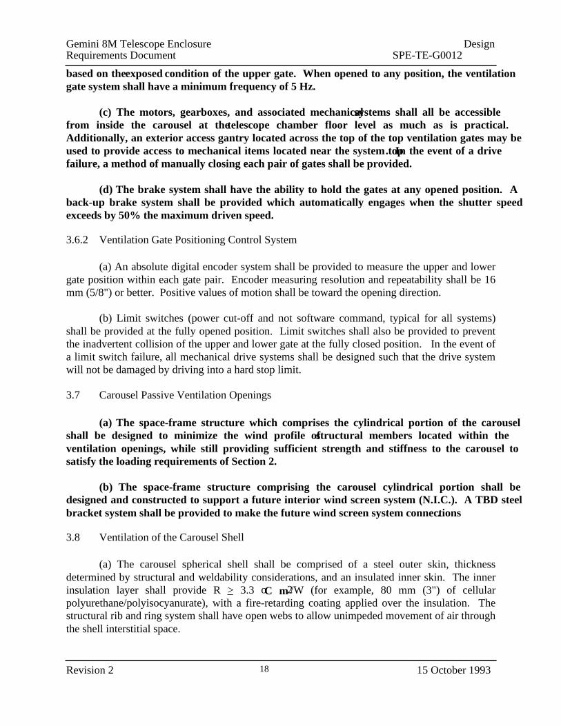
based on the exposed condition of the upper gate. When opened to any position, the ventilationgate system shall have a minimum frequency of 5 Hz.
(c) The motors, gearboxes, and associated mechanical systems shall all be accessiblefrom inside the carousel at the telescope chamber floor level as much as is practical.Additionally, an exterior access gantry located across the top of the top ventilation gates may beused to provide access to mechanical items located near the system top. In the event of a drivefailure, a method of manually closing each pair of gates shall be provided.
(d) The brake system shall have the ability to hold the gates at any opened position. Aback-up brake system shall be provided which automatically engages when the shutter speedexceeds by 50% the maximum driven speed.
3.6.2 Ventilation Gate Positioning Control System
(a) An absolute digital encoder system shall be provided to measure the upper and lowergate position within each gate pair. Encoder measuring resolution and repeatability shall be 16mm (5/8") or better. Positive values of motion shall be toward the opening direction.
(b) Limit switches (power cut-off and not software command, typical for all systems)shall be provided at the fully opened position. Limit switches shall also be provided to preventthe inadvertent collision of the upper and lower gate at the fully closed position. In the event ofa limit switch failure, all mechanical drive systems shall be designed such that the drive systemwill not be damaged by driving into a hard stop limit.
3.7 Carousel Passive Ventilation Openings
(a) The space-frame structure which comprises the cylindrical portion of the carouselshall be designed to minimize the wind profile of structural members located within theventilation openings, while still providing sufficient strength and stiffness to the carousel tosatisfy the loading requirements of Section 2.
(b) The space-frame structure comprising the carousel cylindrical portion shall bedesigned and constructed to support a future interior wind screen system (N.I.C.). A TBD steelbracket system shall be provided to make the future wind screen system connections.
3.8 Ventilation of the Carousel Shell
(a) The carousel spherical shell shall be comprised of a steel outer skin, thicknessdetermined by structural and weldability considerations, and an insulated inner skin. The innerinsulation layer shall provide R >_ 3.3 oC m2/W (for example, 80 mm (3") of cellularpolyurethane/polyisocyanurate), with a fire-retarding coating applied over the insulation. Thestructural rib and ring system shall have open webs to allow unimpeded movement of air throughthe shell interstitial space.
Gemini 8M Telescope Enclosure DesignRequirements Document SPE-TE-G0012
Revision 2 18 15 October 1993

(b) The fire retardent coating provided shall have equivalent performance specificationsto the U.L. rated product, "Staytex."
3.8.1 Passive Ventilation
In order to achieve the Gemini science requirements, a buoyancy-driven, passive air flow circuitmust exist between the ambient air, the carousel shell system, and back to the ambient air duringthe daytime, as shown in Figure 3-8. The introduction of the ambient air shall be as low inheight as practical on the carousel, and the exhaust of this air shall be as high as practical on thecarousel. This flow circuit will not allow air exchange with the interior of the telescope chamberor any part of the stationary floor active ventilation system by closing the air damper system(N.I.C.) located in the enclosure base. The passive ventilation system must have the ability to beshut off during nighttime use of the telescope by means of a damper system located near the topof the carousel. Localized plenums (potentially, guide columns for the ventilation gates) conveyair between the enclosure base and the spherical shell air volume.
3.8.2 Active Ventilation
(a) In order for the Gemini telescopes to attain the seeing error budget at low or zeroambient wind speeds, active flushing of ambient air through the telescope chamber and throughthe carousel shell must occur at night. This air flow regime is shown Figure 3-9.
(b) Thermal analysis has shown that 200,000 m3/hr of ambient air must be drawn throughthe carousel shell. The source of make up air for the shell active ventilation must originate nearthe top of the arch girder/carousel shell interface. The air must then be drawn downward in auniform manner through the shell, across the open ventilation gate, across the carousel rotatinginterface, and finally into the enclosure base floor plenum. Ambient air flow must also be drawnthrough the arch girders, and the required air volume is pending further analysis. The air flowentrance for the daytime passive ventilation will be closed off by an air damper system (N.I.C.)located in the enclosure base to prevent a short circuit of the incoming air path (i.e. through thepassive ventilation openings).
3.9 Carousel Exterior Surface Coating
All exterior surfaces of the carousel, including the shutter and ventilation gates, shall be finishedwith Lo-Mit, or an equivalent coating approved by AURA. The finish shall be durable against
ultraviolet exposure, airborne dust impact , and the conditions specified in Section 2.
3.10 Shutter Crane
(a) The functional requirements for this crane are as follows:
With the platform lift located at the lower level of the enclosure, lift separately the primary
mirror, telescope components, primary mirror cell, and mirror coating chamber off the back ofa truck parked on the platform lift;
Gemini 8M Telescope Enclosure DesignRequirements Document SPE-TE-G0012
Revision 2 19 15 October 1993

Assemble sections of the telescope structure (one-piece azimuth track, telescope mount,
telescope tube);
By means of an interface lifting shaft, lift the primary mirror when located in the wash area of
the coating chamber room.
(b) The crane shall be located within the upper shutter section, and shall be rated for a
capacity of 40,000 kg (44 tons) . Horizontal tangential crane movement is provided by the
rotation of the carousel. Its radial range shall allow it to reach any position on the floor of the
telesocope chamber, except for a small perimeter area adjacent to the carousel ring girder. Figure
3-10 illustrates the region of the floor that is accessible without exposing the interior of the
telescope chamber. T he location of the crane within the upper shutter section shall be optimized
to reach the center portion of this region, and the interface coating chamber lifting shaft, without
causing the shutter system to expose the interior.
(c) The crane mechanisms shall be located above the inner skin of the upper shutter. A
localized raised area on the exterior surface of the shutter may be used for this purpose.
3.10.1 Interface With the Coating Chamber Room Lifting Shaft
Figure 3-10 locates the coating chamber room lifting shaft (N.I.C.) penetration through thestationary telescope chamber floor. CCC shall provide a locking pin system to hold the uppershutter in position, independent of the cable drive system, directly above the lifting shaft whenthe primary mirror is being lifted. The carousel azimuth motion shall contain a predeterminedstop location to locate the crane directly above the lifting shaft.
3.10.2 Shutter Crane Operation
The hook travel length shall extend from a parked position within the shutter to a position 2000mm (6’-7") above the enclosure lower floor level, with the crane cable located at the interior edge(closest to the telescope pier) of the platform lift opening. The crane will operate at two speedscommensurate with economical construction of the crane system. Because of the sensitive natureof primary mirror lifting, the slow speed shall be TBD mm/min.
3.10.3 Shutter Crane Controls
(a) The shutter crane must be individually operable from only one location at a time:either the telescope chamber or the coating chamber room. CCC shall provide a control handpaddle with 10 m (32’-10") of cable, and provide a hard-wired hand paddle connection socketadjacent to the platform lift (see Figure 3-11). CCC shall also provide the hard-wired coatingchamber room hand paddle socket. The hand paddle cable connector shall make positiveterminal contact, with minimal degradation over time, to either socket and shall be positivelylocked in place during use. When not in use, each socket shall be provided with a cover andretainer.
Gemini 8M Telescope Enclosure DesignRequirements Document SPE-TE-G0012
Revision 2 20 15 October 1993

(b) In the event the cable is accidently removed from the socket when operating the crane,all power shall be shut off in the crane, top shutter, and carousel azimuth rotation systems.
(c) The hand paddle will include the following controls and status lights:
1. Shutter crane power.2. Shutter crane power status.3. Shutter crane off/up/down switch.4. Shutter crane lift fast/slow switch.5. Crane stop.6. Top shutter upward motion.7. Top shutter downward motion.8. Top shutter motion stop.9. Carousel positive azimuth rotation.
10. Carousel negative azimuth rotation.11. Carousel rotation stop
(d) The hand paddle socket located in the coating chamber room shall contain signalwires for the shutter crane power, shutter crane power status light, shutter crane off/up/downswitch and shutter crane lift fast/slow switch only.
(e) An interlock system shall be employed to prevent carousel azimuth rotation whencrane loading and position, coupled with environmental loads, imminently will cause bogieassemblies to "bottom out."
3.11 Permanent Arch Girder Lifting Lugs
The functional requirement for the lifting lugs is to provide rigging points for future needs.Provide lifting lugs on each arch girder at a spacing not to exceed five meters on center. Eachgeneral lifting lug shall have a working vertical capacity of 10,000 kg (11 tons), and a workinghorizontal capacity of 1000 kg (1.1 tons) before the application of impact factors.
3.12 Carousel Electrical Systems
3.12.1 Electrical Power and Data Transmission
(a) Electrical power shall be supplied by CCC to the carousel by a slip ring and brushcarrier system. This system shall have sufficient capacity to operate the peak carousel powerdemand, plus a sufficient amount of power for a future wind screen system. A separate slip ringand brush carrier system shall be dedicated for grounding use.
(b) Power supplied to the carousel across the slip ring system for both Mauna Kea andCerro Pachon shall be 277/480 Volt, three phase, 60 Hz, with neutral, to reduce amperagetransfer. If 120/208 Volt, three phase power is required locally, then step down transformers,located in the shell ventilation stream, shall be used.
Gemini 8M Telescope Enclosure DesignRequirements Document SPE-TE-G0012
Revision 2 21 15 October 1993
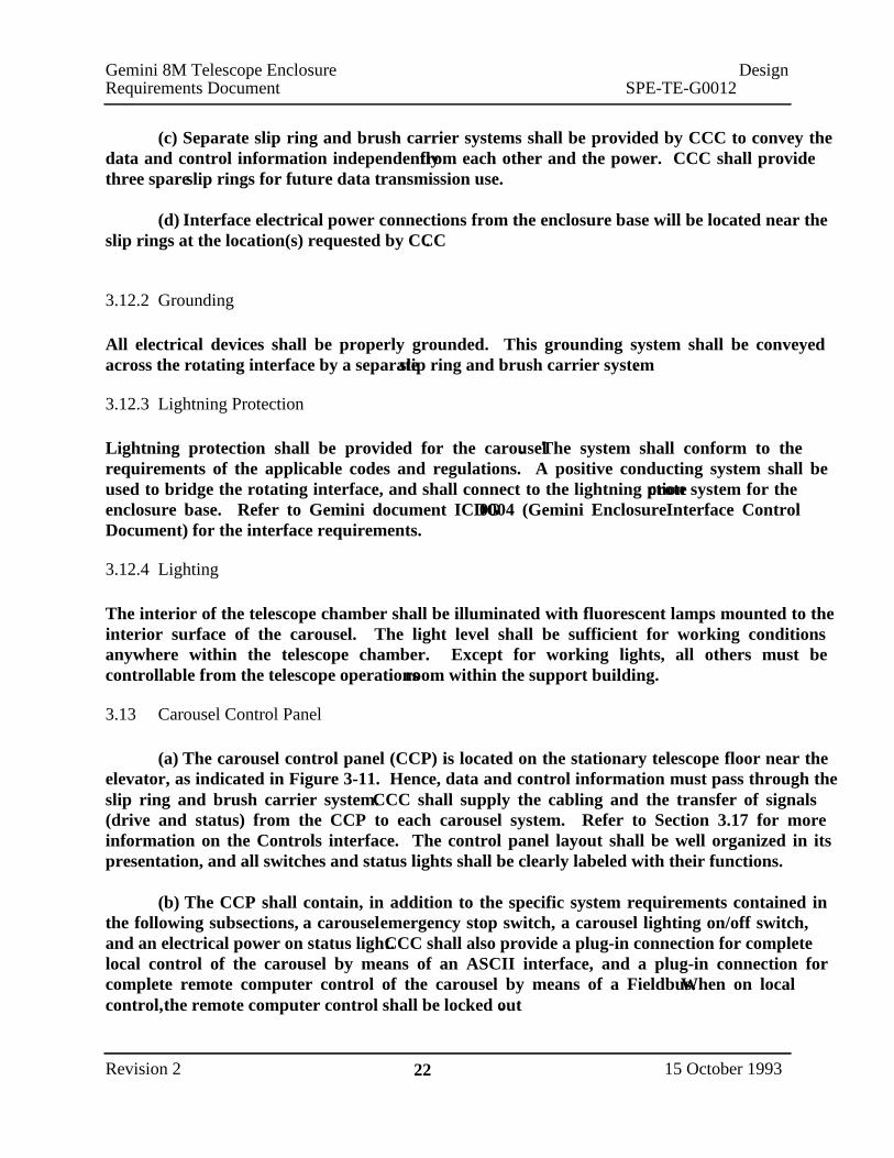
(c) Separate slip ring and brush carrier systems shall be provided by CCC to convey thedata and control information independently from each other and the power. CCC shall providethree spare slip rings for future data transmission use.
(d) Interface electrical power connections from the enclosure base will be located near theslip rings at the location(s) requested by CCC.
3.12.2 Grounding
All electrical devices shall be properly grounded. This grounding system shall be conveyedacross the rotating interface by a separate slip ring and brush carrier system.
3.12.3 Lightning Protection
Lightning protection shall be provided for the carousel. The system shall conform to therequirements of the applicable codes and regulations. A positive conducting system shall beused to bridge the rotating interface, and shall connect to the lightning protection system for theenclosure base. Refer to Gemini document ICDG0004 (Gemini Enclosure Interface ControlDocument) for the interface requirements.
3.12.4 Lighting
The interior of the telescope chamber shall be illuminated with fluorescent lamps mounted to theinterior surface of the carousel. The light level shall be sufficient for working conditionsanywhere within the telescope chamber. Except for working lights, all others must becontrollable from the telescope operations room within the support building.
3.13 Carousel Control Panel
(a) The carousel control panel (CCP) is located on the stationary telescope floor near theelevator, as indicated in Figure 3-11. Hence, data and control information must pass through theslip ring and brush carrier system. CCC shall supply the cabling and the transfer of signals(drive and status) from the CCP to each carousel system. Refer to Section 3.17 for moreinformation on the Controls interface. The control panel layout shall be well organized in itspresentation, and all switches and status lights shall be clearly labeled with their functions.
(b) The CCP shall contain, in addition to the specific system requirements contained inthe following subsections, a carousel emergency stop switch, a carousel lighting on/off switch,and an electrical power on status light. CCC shall also provide a plug-in connection for completelocal control of the carousel by means of an ASCII interface, and a plug-in connection forcomplete remote computer control of the carousel by means of a Fieldbus. When on localcontrol, the remote computer control shall be locked out.
Gemini 8M Telescope Enclosure DesignRequirements Document SPE-TE-G0012
Revision 2 22 15 October 1993

(c) Local control switches and status lights shall be provided for each carousel system as
detailed in the following subsections.
3.13.1 Carousel Azimuth Motion
1. Local/remote switch.
2. Local speed switch: track/medium/fast.
3 . Main drives positive rotation.
4. Main drives negative rotation.
5. Tracking drives positive rotation (step).
6 . Tracking drives negative rotation (step).
7 . Infinite position rate control potentiometer with speed percentages shown in 10%
increment marks.
8. Rotation stop.
9. Emergency operation key-operated switch: on/off .
10 . Emergency operation key-operated switch : positive rotation/negative rotation/off .
11 . Current draw meters (in AC amperes) for each drive motor.
12 . Status lights for local operation ready, azimuth drive power module, and status of each
azimuth drive module.
3.13.2 Upper Shutter Motion
1. Local/remote switch.2. Local speed switch: track/slow/fast.3. Main drives raise.4. Main drives lower.5. Tracking drives raise (step).6. Tracking drives lower (step).7. Motion stop.8. Overtravel bypass switch: raise/lower/off.9. Emergency operation key-operated switch: raise/lower/off.
10. Current draw meters (in AC amperes) for each drive motor.11. Status lights for local operation ready, each upper shutter power module, each upper
shutter drive module, shutter crane hook up, upper shutter overtravel raise, and uppershutter overtravel lower.
3.13.3 Lower Shutter Motion
1. Local/remote switch.
2. Local speed switch: track/slow/fast.3 . Main drives raise .
4 . Main drives lower .5 . Tracking drives raise (step).
6 . Tracking drives lower (step).
7 . Motion stop.
Gemini 8M Telescope Enclosure DesignRequirements Document SPE-TE-G0012
Revision 2 23 15 October 1993

8. Overtravel bypass switch: raise/lower/off.9. Emergency operation key-operated switch: raise/lower/off.
10. Current draw meters (in AC amperes) for each drive motor.11. Status lights for local operation ready, each lower shutter power module, each lower
shutter drive module, lower shutter overtravel raise, and lower shutter overtravel lower.
3.13.4 Ventilation Gate No. 1 Motion
1. Local/remote switch.2. Raise.3. Lower.4. Motion stop.5. Emergency operation key-operated switch: raise/lower/off.6. Current draw meters (in AC amperes) for each drive motor.7. Status lights for local operation ready, each ventilation gate power module, and each
ventilation gate drive module.
3.14.5 Ventilation Gate No. 2 Motion
1. Local/remote switch.
2. R aise.
3 . L ower.
4. Motion stop.
5. Emergency operation key-operated switch: raise/lower/off.
6 . Current draw meters (in AC amperes) for each drive motor.
7. Status lights for local operation ready, each ventilation gate power module, and each
ventilation gate drive module.
3.15 Carousel Radio Remote Control
(a) A radio control panel shall be provided to control the main movements of each of
carousel system as follows:
1. Radio control on/off switch with battery status light.
2 . Carousel emergency stop switch.
3. Carousel lighting on/off switch.
4. Carousel azimuth motion on/off switch, and carousel azimuth positive rotation/no
rotation/negative rotation switch.
5. Upper shutter motion on/off switch, fast/medium/slow switch, and raise/no motion/lower
switch.
6. Lower shutter motion on/off switch, fast/medium/slow switch, and raise/no motion/lower
switch.
7. Ventilation gate no. 1 motion on/off switch, and raise/no motion/lower switch.
8. Ventilation gate no. 2 motion on/off switch, and raise/no motion/lower switch .
Gemini 8M Telescope Enclosure DesignRequirements Document SPE-TE-G0012
Revision 2 24 15 October 1993

(b) When on remote control, the remote computer control and CCP shall be locked out.
(c) The operating range for the radio remote control shall be limited to the confines of thetelescope chamber. The Gemini CCP shall require the proper, unique code from the radio remotecontrol prior to accepting commands from the remote unit. The remote control system shall notbe affected by external radio interference.
3.16 Carousel Emergency Stops
(a) CCC shall provide the Gemini facility with seven (7) emergency stop controls. Thelocation for these controls are shown on Figure 3-11 and are as follows:
1. Four controls located on the stationary floor portion of the telescope chamber atapproximately equal intervals: one on the CCP, one adjacent to the platform lift controls,and the other two located near the telescope chamber air conditioning units.
2. One control located on the carousel radio remote control.3. One control located on the lower floor level of the enclosure base adjacent to the platform
lift controls.4. One control located within the support facility within the telescope operations room.
(b) Actuation of any emergency stop button shall remove power from all carousel drivemotors (azimuth motion, upper shutter and lower shutter motion, ventilation gate motion, andshutter crane).
3.17 Controls Interface
The enclosure control system is a joint effort between CCC, AURA, and the ECSWPR. There
are a number of levels of interface control required to make this joint effort successful.
3.17.1 Control Philosophy
(a) This interface will provide a natural demarcation between the control system provided
by CCC and that provided by AURA.
(b) CCC is required to:
U se a Programmable Logic Controller (PLC) to interface between the Carousel Control Panel
and the actuators and sensors used on the carousel.
U se the Allen-Bradley Fieldbus to communicate between the PLC and the local controllers of
the actuators and sensors.
Provide a means of attaching a video display terminal to the system in order to execute ASCII
commands
Provide ASCII control commands that will control all the functionality of the enclosure (some
functionality may not be included for safety reasons).
Gemini 8M Telescope Enclosure DesignRequirements Document SPE-TE-G0012
Revision 2 25 15 October 1993

Provide ASCII status commands that will enable the complete status of the enclosure to beretrieved, including devices which have no computer control, devices which have status only,and interlocks.Provide a means of interrupting a command in progress both via the ASCII interface and viathe Fieldbus.
(c) CCC will communicate to AURA its control philosophy in advance of Contractexecution.
3.17.2 Transport and Protocol Level Interface
(a) This interface will allow the AURA enclosure control system (N.I.C.) to interface tothe CCC carousel control system.
(b) AURA would prefer to interface to the PLC using a commercial VME module(N.I.C.) via Fieldbus. This VME module would be resident in a VME crate (N.I.C.) which wouldbe running the VxWorks real time operating system from Wind River Systems (N.I.C.). It isAURA’s responsibility to implement and provide this system. AURA already has softwaredrivers for a number of VME modules which interface to the Allen Bradley Fieldbus. AURAwill provide a list of these modules to CCC within 30 days of Contract execution. CCC willprovide the hardware and electrical means of interfacing to one of these modules - this meansshall be detailed at the 25% review (it is expected that CCC will provide a Fieldbus connectionon the Carousel control panel). It will be AURA’s responsibility to provide the VME module,software, cabling and connectors up to this interface.
3.17.3 Command Level Interface
(a) This interface will allow the AURA control system to access the functionality of theCCC control system.
(b) CCC shall use a consistent syntax for the ASCII commands which CCC implementsfor control and status via the ASCII terminal. While AURA intends to interface directly to theFieldbus for control and status the intent is to leave open the option of AURA interfacing via anASCII command interface if that proves desirable later - thus the command syntax must becapable of being parsed by a computer.
(c) It shall be possible for the user to interrupt a command in progress at any time. It shallnot be possible to put the system in a blocked state where the user cannot regain control of thesystem. This capability must be provided both via the ASCII interface and the Fieldbus interface.
(d) CCC will communicate to AURA the command syntax, a list of all commands andtheir responses, and the means of interrupting the system at the time of the 25% design review.
3.17.4 Testing of AURA - CCC Control Interface
Gemini 8M Telescope Enclosure DesignRequirements Document SPE-TE-G0012
Revision 2 26 15 October 1993
It is understood that it is AURA’s responsibility to design, implement, and test this interface. It is
understood by CCC that AURA needs access to the CCC system in order to test AURA’s design.
In advance of the 80% design review CCC will allow AURA, at AURA’s expense, access to a
prototype CCC control system in order to test out a subset of AURA’s command functionality.
This subset is to include, at a minimum, one control command, one status command, and
interruption of a command in progress. CCC will provide a prototype system with a motor and
encoder, in order for AURA to perform this test. The timing and location of this test will be at
CCC’s convenience.
3.18 Instrumentation Flat Field
Provisions shall be made for the support of a calibration flat field (N.I.C.) between the arch
girders (see Figure 3-12). Interface loading and electrical requirements will supplied by AURA
by March 1, 1994. The connection points and adequacy shall be the responsibility of CCC.
3.19 Interior Surface Finishes
All steel not exposed to view shall be primed with an inorganic zinc coating. All steel exposed
to view shall be coated with a durable paint suitable to the conditions encountered on Mauna Kea
and Cerro Pachon.
3.20 Enclosure Platform Lift
(a) The functional requirements for the platform lift are as follows:
Provide a safe conveying system for transporting the primary mirror, mirror cell, and support
frame between the telescope chamber and the enclosure base;
Provide a safe conveying system for exchanging top ends on the telescope;
Provide a safe conveying system for transporting sections of the telescope structure during
installation;
Provide a method for conveying instrumentation packages into and out of the telescope
chamber if too large to bring up in the enclosure personnel elevator;
Participate in the active floor ventilation system.
(b) The platform lift is shown in Figure 3-13. Figure 3-2 shows the overall configuration
of the lift with respect to grade elevation and platform travel. The required platform size is
shown in the upper right-hand portion of Figure 3-14.
(c) In general terms, the platform lift is supported by the stationary chamber floor at the
interior edge, and by the guide columns at the exterior edge. V ertical movement is provided by a
system of four screw jacks loaded in tension. The interior columns extend down from the
chamber floor to within a few centimeters of the finished floor. This gap below the columns
prevents vibration from being transferred from the enclosure into the telescope pier foundation.
This gap shall be closed by a jacking mechanism when the platform lift is in use in order to
transfer loads directly into the foundation.
Gemini 8M Telescope Enclosure DesignRequirements Document SPE-TE-G0012
Revision 2 27 15 October 1993

(d) When located in its parked position at the telescope chamber level, the platform liftshall fully participate in the active ventilation system with the remainder of the floor. Ventilationholes shall be provided around three sides to match holes located in the surrounding floor asrequired.
(e) Figure 3-14 illustrates the required steps for removing the primary mirror from thetelescope chamber, and Figure 3-15 provides detail on the primary mirror cart (N.I.C.). Theprimary mirror cell cart will be conveyed by the use of four air bearings. CCC shall design thefloor of the platform to conform to the requirements of this system.
(f) The platform lift must be locked together with the rotating telescope floor to limitdifferential movement. As the primary mirror cart transfers from the telescope floor to theplatform lift, relative vertical movement between the two floors shall be limited to 1.6 mm(1/16"). CCC shall provide this locking system, and coordinate the connection detail throughAURA.
(g) Figure 3-16 illustrates the required steps for exchanging telescope top ends, andFigure 3-17 provides detail on the top end cart. The top end cart (N.I.C.) will also be conveyedby the use of air bearings with a middle guide rail. CCC shall design the floor of the platform toconform to the requirements of this system.
(h) The maximum loading on the platform lift will be the combined mass of the primarymirror, the primary mirror cell, and the mirror cell cart. The combined load will be 110,000 kg(121 tons). Sufficient load capacity shall be available along the area of influence of the airbearings.
(i) The platform lift shall have two speeds, based on the load placed on the lift. For theloading range between 55,000 kg and 110,000 kg, the trip from the enclosure base floor to thetelescope chamber floor shall require no more than 8 minutes (approximately 1700 mm/min).For all other lifts, the time required shall be no more than 4 minutes.
(j) The platform lift shall have an auxiliary brake system to hold its vertical position inthe event of drive shaft or motor failure. The two speed arrangement shall possess a fail-safe toprevent a load of 50% through 100% of platform capacity from attempting to be transported atthe faster speed. The drive system shall possess a system to protect the remaining drives if onedrive locks or fails.
(k) The controls for the platform shall be located both on the platform lift and at theenclosure base floor level. An intercom system (N.I.C.) between the upper and lower floorcontrol panels will be provided by others. In order to operate the platform lift, two people mustsimultaneously operate the same control on each panel. In this manner, the areas above andbelow the lift will be checked for safety.
Gemini 8M Telescope Enclosure Design
Requirements Document SPE-TE-G0012
Revision 2 28 15 October 1993

(l) A handrail system must be in place around the perimeter of the lift under all operating
conditions. Interlocks shall be designed into the system to prevent movement if handrail sections
are missing.
3.21 Interior Surface Finishes
All steel not exposed to view shall be primed with an inorganic zinc coating. All steel exposed
to view shall be coated with a durable paint suitable to the conditions encountered on Mauna Kea
and Cerro Pachon.
Gemini 8M Telescope Enclosure Design
Requirements Document SPE-TE-G0012
Revision 2 29 15 October 1993

Section 4
CAROUSEL OPERATION
4.1 Telescope Observing Conditions
The carousel shall perform all the separate functions listed within this Design Requirements
Document. In addition, the carousel must have the ability to combine system motions into a
global motion. The following global mo tions are required:
1. From stopped position and in either direction, azimuth rotation of the carousel of 1
arcminute or less , combined with upper shutter motion and lower shutter motion of 1
arcminute or less , in 5 seconds or less .
2 . From stopped position and in either direction, azimuth rotation of the carousel of less
than 10 degrees, combined with upper shutter motion and lower shutter motion of less
than 10 degrees , in 30 seconds or less .
3 . From stopped position and in either direction, azimuth rotation of the carousel of 180
degrees, combined with upper shutter motion and lower shutter motion from one extreme
to the other (15 degrees and 92 degrees), in 300 seconds or less .
4 . Shutter crane operation with full 40,000 kg loading: shutter motion for radial movement,
and carousel azimuth rotation for tangential movement.
5 . Ventilation gate no. 1 operation: open and stop to any position between fully open and
fully closed independent of ventilation gate no. 2.
6 . Ventilation gate no. 2 operation: open and stop to any position between fully open and
fully closed independent of ventilation gate no. 1.
Gemini 8M Telescope Enclosure DesignRequirements Document SPE-TE-G0012
Revision 2 30 15 October 1993

Section 5
INSTALLATION ACCEPTANCE TESTING
(a) Upon completion of the Work, CCC shall demonstrate that each system performsaccording to the requirements set forth in this Specification. The following system capabilitiesshall be demonstrated for final acceptance, and all demonstrations shall be performed during boththe nighttime and daytime. The demonstrations include, but are not limited to, the following:
1. Carousel rotation at the maximum slew rate, at various slew speeds using the infinitelyvariable control, and in stepwise tracking motion. Equal performance shall bedemonstrated in both the clockwise and counter-clockwise rotational directions.
2. Upper viewing aperture shutter motion at the fast speed, slow speed, and stepwisetracking motion. When tracking, the upper shutter shall be synchronized in motion withthe lower shutter. Equal performance shall be demonstrated in all upward and downwardmotions.
3. Lower viewing aperture shutter motion at the fast speed, slow speed, and stepwisetracking motion. When tracking, the lower shutter shall be locked in motion with theupper shutter. The ability to drive the wind blind system shall be demonstrated. Equalperformance shall be demonstrated in all upward and downward motions.
4. Independent motion of exterior ventilation gate system no. 1 and no. 2 at the onerequired speed in both an upward and downward direction. The ability to stop at anyposition shall be demonstrated.
5. Exterior ventilation gate system motion and performance with simulated balanced andunbalanced ice loading.
6. Carousel shell active ventilation system.7. Carousel shell passive ventilation system.8. Integral 40 metric tonne shutter crane operated under full load over the required range of
motion, and certified for performance.9. Electrical power and data transmission slip ring and brush carrier system quality along its
full perimeter.10. Operation of the complete command set, including control and status commands. For
each command, testing of interruption shall be performed using an ASCII terminalconnected to the control system.
11. Operation of any one of the following systems while simultaneously rotating theenclosure: shutter and wind blinds, exterior ventilation gates, and the carousel shellactive ventilation system.
12. The positioning accuracy and repeatibility of all encoders within the carousel.
Gemini 8M Telescope Enclosure DesignRequirements Document SPE-TE-G0012
Revision 2 31 15 October 1993

13. The effectiveness of all braking systems within the carousel, including the emergencystop.
14. Method of operating each system with failed motors or drives to fully close the enclosure.15. Platform lift operated under full rated loading at the slow speed, and at half rated load for
the fast speed. 16. Operation of the radio control panel functions when standing at any location within the
carousel. The uniqueness of the radio frequency utilized must be demonstrated.
(b) For a period of 12 months after initial acceptance of the enclosure by AURA, CCCshall be responsible for any and all corrections to bring non-compliant systems back intocompliance.
Gemini 8M Telescope Enclosure DesignRequirements Document SPE-TE-G0012
Revision 2 32 15 October 1993