general catalogue - koronkakoronka.co.uk/site/templates/uploads/links_files/lowara catalogue.pdf ·...
TRANSCRIPT

General Catalogue

P-PAB-PSA SeriesPeripheral Pumps
SVI SeriesSubmersible VerticalElectric Pumps
FH (FHE, FHS, FHF) SeriesCast Iron FlangedCentrifugal Pumps
SV SeriesVertical MultistageCentrifugal Pumps
38
SP SeriesSelf-priming Pumps withSide Channel
BG SeriesSelf-priming CentrifugalPumps with Ejector
HM - HMS SeriesHorizontal Multistage CentrifugalPumps
CEA-CA SeriesAISI 304 Stainless SteelCentrifugal Pumpsfor Clear Waters
CO SeriesAISI 316L Stainless SteelCentrifugal Pumps withOpen Impellerfor Dirty Waters
SH (SHE, SHS, SHF) SeriesAISI 316L Stainless SteelFlanged Centrifugal Pumps
Contents P-PAB
-PSA
SPBG
HM-H
MS
CEA-
CACO
FHSH
SV
5
11
14
17
22
33
70
99
SVI
114®
Do it 100%
RECYCLEDPAPER
OZ6-FZ6-FZN6 SeriesSubmersible Pumpsfor 6” Wells
4OS-OS6 SeriesSubmersible Motorsfor 4” and 6” Wells
FC (FCE, FCS) SeriesIn-line Close-coupledPumps
NCLG4 SeriesIn-Line twin electric pumps
Sphere Block Units and DominosystemPressure Vessel with a Single-phasePump for Residential Applications
Contents
PRES
SURE
BOO
STER
UN
ITS
FIRE
FIG
HTIN
GSY
STEM
SPHE
RE U
NITS
BLOC
KUN
ITSDO
MIN
OSYS
TEM
NCL
G4
SCU
BAG
SOZ
6-FZ6-
FZN6
4OS-
OS6
Pressure Booster Units2, 3, 4 Pumps for ApartmentBlocks, Industrialand Fire-fighting Applications
Fire Fighting SystemUtilising Borehole Pumps
DominoAutomatic Control Devicefor Single-phase Pumpsfor Residential Applications
SCUBA + SCUBA CG SeriesClose-coupled SubmersiblePumps for 5” Wells
GS SeriesSubmersible Pumpsfor 4” Wells
120
121
118
123
148
151
162
174
DOM
INO
116FC
145

F4-F6 SeriesSubmersible Motorsfor 4” and 6” Wells
DOC SeriesSubmersible Pumpsfor Dirty Water(Residential Applications)
SINGLEBOX - DOUBLEBOX SeriesPrefabricated Lifting Stationsfor Waste Water entrained solids
DL SeriesSubmersible Pumpsfor Waste Water with entrained solids
GL-GLV SeriesSubmersible Pumps for waste water
DOMO SeriesAISI 304 Stainless steelSubmersible Pumpsfor Waste Water with entrained solids
177
S 8” - 10” - 12” SeriesSubmersible Pumpsfor 8” - 10” and 12” Wells
Contents
MINIBOX SeriesPrefabricated CompactLifting Stationsfor Dirty Water
DIWA SeriesAISI 304 Stainless SteelSubmersible Pumpsfor Dirty Water
DN SeriesSubmersible Pumpsfor Dirty Water
180
182
185
187
190
193
197
204
207
SF4
-F6
DO
CM
INIB
OXD
IWA
DN
DO
MO
DL
GL-
GLV
SIN
GLE
BOX
DO
UBL
EBO
X

Pump Control Boxes
Contents
GrinderSubmersible pump for dirtywater containing solids
DiggerSubmersible Pumpsfor Dirty Water(contractor)
HydrovarFrequency Converters
Diaphragm Pressure Vessels
Accessories
221
243
247
248
FDL-
FXD
L-F
BDL
GRIN
DER
DIGG
ERCO
NTR
OL
PAN
ELS
HYDR
OVAR
DIA
PHRA
GM
PRES
SURE
VES
SELS
ACCES
SORIE
S211
217
219
FDL-FXDL-FBDL SeriesPumps for Waste Water with entrainedsolids and Industrial Applications(cast iron, AISI 316 stainless steel,bronze construction)

APPLICATIONS
•Clear water handling for domestic use.
•Lawn sprinkling.
•Assembled with pressure vessels for pressure boosting invarious applications.
•Washing.
•Boiler feed (the PSA series is speciallyindicated).
•Use in hot water systems (PAB and PABLB models)
SPECIFICATIONS
•P-PAB series with front suction and radial delivery.PSA-PABLB series with radial suction and delivery.
•Capacity: up to 62 l/min (3,72 m3/h).
•Head: up to 82 m (8,2 bar).
•Maximum operating pressure: 8 bar (10 barfor PSA series).
•Continuous duty.
•Temperature of pumped liquid: -10°C to+40°C for P series, 80°C for PSA and PAB,PABLB series.
•Max ambient temperature: 40°C.
•Enclosed motor with internal ventilation through casingfor series P, (P16, P21, P30, P40) pumps, enclosed withexternal ventilation and aluminium alloy casing for (P60,P70), PSA and PAB, PABLB series pumps.
•Versions:Single-phase 220 V 50 Hz, permanently connectedcapacitor and built-in automatic reset overloadprotection.Three-phase 220-240/380-415 V 50 Hz, thermaloverload protection to be provided by user.
•Power up to 1,1 kW.
•Class F Insulation.
• IP44 protection for models P16, P21, P30,P40, PAB, PABLB, (IP55 for models P60,P70 and PSA).
5
P-PAB
-PSA
P-PAB-PSA SERIESPERIPHERALPUMPSPeripheral pumps can develop high heads usinglower-powered motors. The P-PAB-PSA series isthe result of Lowara’s thirty-year experience inthe manufacture of these products.
TABLE OF MATERIALSPART MATERIAL
Pump body CAST IRON * (P, PSA)Adapter (PSA HAS BRASS FITTINGS
TO PREVENT RUST FROM JAMMINGTHE IMPELLER)
BRONZE (PAB, PABLB)
Impeller BRASS
Shaft extension (P16, P21, P30, P40) STAINLESS STEEL(AISI 303 – DIN 1.4305)
Shaft extension (P60, P70, PSA, PAB, STAINLESS STEELPABLB) (AISI 416 – DIN 1.4005)
Fill plug BRASS
Mechanical seal CARBON/CERAMIC/NBR
O-ring seals NBR
* P version available in a special option with pump body in bronze.

6
P-PAB
-PSA
P SERIESOPERATING CHARACTERISTICS AT 2850 rpm 50 Hz
PUMP TYPE
l/min 0 8 10 15 20 35 37 40 50 62
m3/h 0 0.48 0.60 0.90 1.20 2.10 2.22 2.40 3.00 3.72
kW HP
RATED
POWER
H = TOTAL HEAD METERS COLUMN OF WATER
Q = DELIVERY
P(M)16 0.3 0.4 43.4 33.0 27.8 22.6 7.1 5.0
P(M)21 0.37 0.5 47.4 37.0 31.8 26.7 11.2 9.1 6.0
P(M)30 0.5 0.7 56.8 47.0 42.1 37.3 22.6 20.7 17.8 8.0
P(M)40 0.6 0.8 62.3 49.0 44.6 31.3 29.5 26.9 18.0
P(M)60 1.1 1.5 76.9 60.0 43.8 41.6 38.2 27.5 16.0
P(M)70 0.75 1 102.6 82.0 76.8 64.0 51.5 18.0
Le prestazioni valgono per liquidi con densità ρ = 1,0 kg/dm³ ed una viscosità cinematica ν = 1 mm²/s. p-2p50_a_th
PUMP TYPE INPUT INPUT CAPACITOR PUMP TYPE
POWER* CURRENT*
220-240 V
A
220-240 V 380-415 V
kW µF / 450 V kW A A
220-240 V THREE-PHASE 220-240 V 380-415 V
kW A µF / 450 V kW A A
SINGLE-PHASE
INPUT
POWER*
INPUT
CURRENT*
INPUT
CURRENT*
PM16 0.5 2.4 10 P16 0.48 1.55 0.9
PM21 0.58 2.8 12.5 P21 0.55 1.9 1.1
PM30 0.8 4 16 P30 0.78 2.8 1.6
PM40 1.15 5.3 20 P40 1.1 3.6 2.1
PM60 1.77 7.95 30 P60 1.72 5.23 3.02
PM70 1.36 6.12 25 P70 1.3 4.36 2.52
*Valori massimi nel campo di funzionamento p-2p50_a_te
These performances are valid for liquids with density ρ = 1.0 kg/dm3 and kinematic viscosity γ = 1 mm2/sec.
* Maximum value in specified range

7
P-PAB
-PSA
PAB SERIESOPERATING CHARACTERISTICS AT 2850 rpm 50 Hz
PUMP TYPE
l/min 0 8 10 15 20 25 30 33
m3/h 0 0.48 0.60 0.90 1.20 1.50 1.80 1.98
kW HP H = TOTAL HEAD METERS COLUMN OF WATER
RATED
POWER
Q = DELIVERY
PABM15 0.37 0.5 43.0 33.0 30.6 24.7 18.9 13.4 8.1 5.0
PABLBM15 0.37 0.5 43.0 33.0 30.6 24.7 18.9 13.4 8.1 5.0
Le prestazioni valgono per liquidi con densità ρ = 1,0 kg/dm³ ed una viscosità cinematica ν = 1 mm²/s. pab-2p50_a_th
PUMP TYPE INPUT INPUT CAPACITOR PUMP TYPE
POWER* CURRENT*
220-240 V
A
220-240 V 380-415 V
kW µF / 450 V kW A A
220-240 V THREE-PHASE 220-240 V 380-415 V
kW A µF / 450 V kW A A
SINGLE-PHASE
INPUT
POWER*
INPUT
CURRENT*
INPUT
CURRENT*
PABM15 0.47 2.1 10 - - - -
PABLBM15 0.47 2.1 10 - - - -
*Valori massimi nel campo di funzionamento pab-2p50_a_te
These performances are valid for liquids with density ρ = 1.0 kg/dm3 and kinematic viscosity γ = 1 mm2/sec.
* Maximum value in specified range

8
P-PAB
-PSA
PSA70 SERIESOPERATING CHARACTERISTICS AT 2850 rpm 50 Hz
PUMP TYPE
l/min 0 2 4 8 10 12 14 16
m3/h 0 0.12 0.24 0.48 0.6 0.72 0.84 0.96
kW HP
RATED
POWER
Q = DELIVERY
H = TOTAL HEAD METERS COLUMN OF WATER
PSA(M)70 0.37 0.5 92.8 82.0 71.1 49.7 39.7 30.4 22.1 15.0
Le prestazioni valgono per liquidi con densità ρ = 1,0 kg/dm³ ed una viscosità cinematica ν = 1 mm²/s. psa-2p50_a_th
PUMP TYPE INPUT INPUT CAPACITOR PUMP TYPE
POWER* CURRENT*
220-240 V
A
220-240 V 380-415 V
kW µF / 450 V kW A A
220-240 V THREE-PHASE 220-240 V 380-415 V
kW A µF / 450 V kW A A
SINGLE-PHASE
INPUT
POWER*
INPUT
CURRENT*
INPUT
CURRENT*
PSAM70 0.75 3.41 16 PSA70 0.76 2.75 1.59
*Valori massimi nel campo di funzionamento psa-2p50_a_te
These performances are valid for liquids with density ρ = 1.0 kg/dm3 and kinematic viscosity γ = 1 mm2/sec.
* Maximum value in specified range

9
P-PAB
-PSA
DIMENSIONS AND WEIGHTS, P SERIES
PUMP TYPE WEIGHT
kg
DIMENSIONS (mm)
A F H L1
DNA DNM
P16-PM16 8.5
P21-PM21 9.5
P30-PM30 11
P40-PM40 11.5
p-2p50_a_td
50
50
55
54.5
Rp 1 Rp 118.5
20
Rp 1
18.5
20
Rp 1
Rp 1
Rp 1
Rp 1
163305 Rp 1
285
153
163
280
153280
PUMP TYPE DNA DNM
C F F1 H H1 H2 L L1 M M1 N N1 K K1 W kg
DIMENSIONS (mm) WEIGHT
P60 155 354 113 180 80 209 78 20 100 124 125 153 9 12 83 Rp 1 Rp 1 8.5
PM60 155 354 68 180 80 217 81 20 100 124 125 153 9 12 83 Rp 1 Rp 1 9.5
P70-PM70 140 314 76 171 71 192 78 18 90 113 112 135 7 12 70 Rp ¾ Rp ¾ 11
p60-70-2p50_a_td

10
P-PAB
-PSA
DIMENSIONS AND WEIGHTS, PAB AND PSA70 SERIES

11
SPSP SERIESSELF-PRIMING PUMPSWITH SIDE CHANNELClose-coupled centrifugal pumps with liquid sidechannel and star impeller. Designed to remainprimed even in the presence of water-dissolvedgases or when the suction line is not filled withliquid.
❏ THE NICKEL-PLATED BRASS IMPELLER ISHOUSED BETWEEN TWO BRASS WEARPLATES IN THE PUMP BODY TO PREVENTJAMMING DUE TO OXIDATION
APPLICATIONS•Water circulation for domestic use.
•Home lawn and garden sprinkler systems.
•Washing and transfer.
•Applications where keeping the pump primed isproblema.
SPECIFICATIONS•Delivery: up to 45 l/min (2,7 m3/h).
•Head: up to 49,3 m.
•Maximum operating pressure: 8 bar.
•Continuous duty.
•Temperature of pumped liquid: -10°C to+40°C.
•Max ambient temperature: 40°C.
•Enclosed motor with external ventilation andaluminium alloy finned casing.
•Versions:Single-phase 220-240 V 50 Hz, permanentlyconnected capacitor and built-in automatic resetoverload protection.Three-phase 220-240/380-415 V 50 Hz, thermaloverload protection to be provided by user.
•Power up to 0.75 kW.
•Class F Insulation.
• IP 55 protection.
TABLE OF MATERIALSPART MATERIAL
Pump body andmotor/pump support CAST IRON
Impeller NICKEL-PLATED BRASS
Front flange,rear diffuser plate BRASSand fill plug
Shaft extension STAINLESS STEEL(AISI 416 – DIN 1.405)
Mechanical seal CARBON/CERAMIC/NBR
O-ring seals NBR

12
SP
SP SERIESOPERATING CHARACTERISTICS AT 2850 rpm 50 Hz
PUMP TYPE
l/min 0 10 20 25 30 35 40 45
m3/h 0 0.6 1.2 1.5 1.8 2.1 2.4 2.7
kW HP
RATED
POWER
Q = DELIVERY
H = TOTAL HEAD METERS COLUMN OF WATER
SP5(T) 0.55 0.75 45.2 39.8 31.1 26.0 20.7 15.4 10.3 5.7
SP7(T) 0.75 1 54.1 49.3 41.5 36.7 31.4 25.7 19.7 13.5
Le prestazioni valgono per liquidi con densità ρ = 1,0 kg/dm³ ed una viscosità cinematica ν = 1 mm²/s. sp-2p50_a_th
PUMP TYPE INPUT INPUT CAPACITOR PUMP TYPE
POWER* CURRENT*
220-240 V
A
220-240 V 380-415 V
kW µF / 450 V kW A A
220-240 V THREE-PHASE 220-240 V 380-415 V
kW A µF / 450 V kW A A
SINGLE-PHASE
INPUT
POWER*
INPUT
CURRENT*
INPUT
CURRENT*
SP5 0.87 4.21 16 SP5T 0.78 2.67 1.54
SP7 1.00 4.60 20 SP7T 0.98 3.53 2.04
*Valori massimi nel campo di funzionamento sp-2p50_a_te
These performances are valid for liquids with density ρ = 1.0 kg/dm3 and kinematic viscosity γ = 1 mm2/sec.
* Maximum value in specified range

13
SP
DIMENSIONS AND WEIGHTS, SP SERIES
PUMP TYPE WEIGHT
kg
SP5(T)
SP7(T)
sp-2p50_a_td
11
12

14
BG
BG SERIESSELF-PRIMING CENTRIFUGALPUMPSClose-coupled centrifugal pumps with built-inejector system, designed to remain primed even inthe presence of water-dissolved gases. Theextensive use of pressed stainless steel ensures ahigh-performance, durable and lightweight pump.
❏ “GARDEN” VERSION AVAILABLE WITHHANDLE, TERMINAL BOX WITHINCORPORATED SWITCH AND 2 m CABLEWITH PLUG
❏ EXTENSIVE USE OF AISI 304 OR AISI 316STAINLESS STEEL
❏ IP 55 MOTOR PROTECTION
APPLICATIONS
•Water handling for domestic use.
•Lawn sprinkling.
•Composition of surge tank units for pressure boosting invarious applications.
•Washing and transfer.
SPECIFICATIONS
•Delivery: up to 70 l/min (4,2 m3/h).
•Head: up to 53 m.
•Maximum operating pressure: 8 bar.
•Maximum total lift 8 m (1”1/4 suction pipe andfoot valve for water at 20°C).
•Continuous duty.
•Temperature of pumped liquid: -10°C to+40°C.
•Max ambient temperature: 40°C.
•Enclosed motor with external ventilation andaluminium alloy finned casing.
•Versions:Single-phase 220-240 V 50 Hz, permanentlyconnected capacitor and built-in automatic resetoverload protection.Three-phase 220-240/380-415 V 50 Hz, thermaloverload protection to be provided by user.
•Power up to 1.1 kW.
•Class F Insulation.
• IP 55 protection.
TABLE OF MATERIALSPART MATERIAL
Pump body, seal-housing, STAINLESS STEELImpeller (AISI 304 – DIN 1.4301)
Diffuser, Ejector THERMOPLASTICMATERIAL SUITABLE FOR
HANDLING DRINKING WATER
Shaft extension STAINLESS STEEL(AISI 316 – DIN 1.4571)
Fill and drain plugs NICKEL-PLATED BRASS
Mechanical seal CARBON/CERAMIC/NBR
O-ring seals NBR

15
BG
BG SERIESOPERATING CHARACTERISTICS AT 2850 rpm 50 Hz
PUMP TYPE
l/min 0 10 20 30 40 50 60 65 70
m3/h 0 0.6 1.2 1.8 2.4 3 3.6 3.9 4.2
kW HP
Q = DELIVERY RATED
POWER
H = TOTAL HEAD METERS COLUMN OF WATER
BG(M)3 0.37 0.5 36.9 30.6 25.6 21.5 17.7 13.8
BG(M)5 0.55 0.75 40.2 35.7 32.0 28.8 25.7 22.4 18.8
BG(M)7 0.75 1 45.4 38.1 34.8 31.7 28.6 25.6
BG(M)9 0.9 1.2 49.6 41.1 37.7 34.8 32.2 29.8 28.6
BG(M)11 1.1 1.5 53.2 45.8 42.5 39.5 36.5 33.5 31.9 30.3
Portate massime in funzione dei dislivelli geodetici in aspirazione con tubo lungo 8 m e valvola di fondo puliti da 1"¼. bg-2p50_a_th
Le prestazioni valgono per liquidi con densità ρ = 1,0 kg/dm³ ed una viscosità cinematica ν = 1 mm²/s.
PUMP TYPE INPUT INPUT CAPACITOR PUMP TYPE
POWER* CURRENT*
220-240 V
A
220-240 V 380-415 V
kW µF / 450 V kW A A
220-240 V THREE-PHASE 220-240 V 380-415 V
kW A µF / 450 V kW A A
SINGLE-PHASE
INPUT
POWER*
INPUT
CURRENT*
INPUT
CURRENT*
BGM3 0.67 2.96 14 BG3 0.68 2.56 1.48
BGM5 0.91 4.33 16 BG5 0.81 2.74 1.58
BGM7 1.11 5 20 BG7 1.1 3.71 2.14
BGM9 1.24 5.54 25 BG9 1.16 4.24 2.45
BGM11 1.43 6.47 30 BG11 1.38 4.59 2.65
*Valori massimi nel campo di funzionamento bg-2p50_a_te
BGM3 0.67 2.96 14 BG3 0.68 2.56 1.48
BGM5 0.91 4.33 16 BG5 0.81 2.74 1.58
BGM7 1.11 5 20 BG7 1.1 3.71 2.14
BGM9 1.24 5.54 25 BG9 1.16 4.24 2.45
BGM11 1.43 6.47 30 BG11 1.38 4.59 2.65
*Valori massimi nel campo di funzionamento bg-2p50_a_te
Maximum delivery depends on geodetic suction lift with clean 8 m pipe and 11/4” foot valve.
These performances are valid for liquids with density ρ = 1.0 kg/dm3 and kinematic viscosity γ = 1 mm2/sec.
* Maximum value in specified range
16
BG
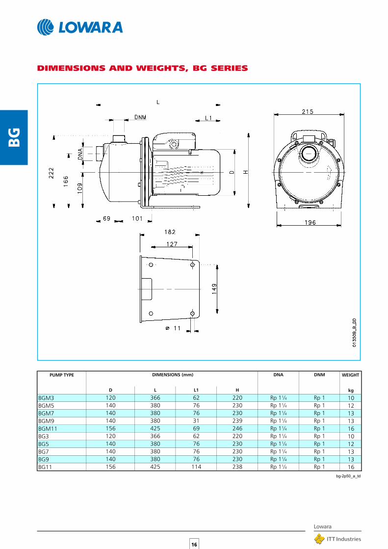
DIMENSIONS AND WEIGHTS, BG SERIES
PUMP TYPE WEIGHT
kgD L L1 H
DNA DNMDIMENSIONS (mm)
BGM3 10
BGM5 12
BGM7 13
BGM9 13
BGM11 16
BG3 10
BG5 12
BG7 13
BG9 13
BG11 16
bg-2p50_a_td
Rp 1
366
140
120
380
62
76
76
114
425
380
380
425
69
366 62
76
120
156
156
140
140
140
31
76
380
380
140
238
230
239
220
230
230
230
246
230
Rp 1
Rp 1
Rp 1
Rp 1
Rp 1
Rp 1
Rp 1Rp 1¼
220 Rp 1¼
Rp 1¼
Rp 1¼
Rp 1¼
Rp 1¼
Rp 1¼
Rp 1¼
Rp 1¼
Rp 1¼
Rp 1
Rp 176380140

17
HM-H
MS
HM-HMS SERIESHORIZONTAL MULTISTAGECENTRIFUGAL PUMPSModern-design noiseless high-efficiency pumps,available in the HM version for domesticapplications and in the HMS version for industrialapplications (made entirely ofAISI 316 stainless steel).
HM APPLICATIONS(AISI 304 + Technopolymer)
•Clean water circulation for domestic use.
•Pressure boosting units for single- or double-familydwelling water supply.
•Irrigation systems.
•Washing.
HMS APPLICATIONS (AISI 316)
•Industrial washing systems.
•Cooling and heating circuits.
•Handling of special liquids (demineralized or softenedwater, washing solutions, oils, etc.).
•Irrigation systems handling water containing nutritiveand/or chemically aggressive substances.
SPECIFICATIONS
•Delivery: up to 120 l/min (7,2 m3/h).
•Head: up to 60 m.
•Continuous duty.
•Max. temperature of pumped liquid:-10°C to +60°C for HM-10°C to +110°C for HMS.
•Maximum operating pressure: 8 bar.
•Enclosed motor with external ventilation andaluminium alloy finned casing.
•Versions:Single-phase 220-240 V 50 Hz, built-in automaticreset overload protection.Three-phase 220-240/380-415 V 50 Hz, overloadprotection to be provided by user.
•Class F Insulation.
•Power up to 0.9 kW.
• IP 55 protection.
TABLE OF MATERIALS
PART MATERIAL
Pump body, Seal-housing, STAINLESS STEELDiffusers, Covers, Spacers (AISI 304 – DIN 1.4301)
Impellers TECHNOPOLYMER SUITED FORHANDLING FOOD PRODUCTS
Shaft extension STAINLESS STEEL(AISI 316L – DIN 1.4404)
Fill and drain plugs NICKEL-PLATED BRASS
Mechanical seal CARBON/CERAMIC/EPDM
O-ring seals EPDM
HM SERIES
PART MATERIAL
Pump body, Seal-housing, STAINLESS STEELDiffusers, Covers, Spacers (AISI 316L – DIN 1.4404)
Impellers, Shaft extension, STAINLESS STEELFill and drain plugs (AISI 316L – DIN 1.4404)
Mechanical seal CARBON/CERAMIC/EPDM
O-ring seals EPDM
HMS SERIES

18
HM-H
MS
HM SERIESOPERATING CHARACTERISTICS AT 2850 rpm 50 Hz
These performances are valid for liquids with density ρ = 1.0 kg/dm3 and kinematic viscosity γ = 1 mm2/sec.

19
HM-H
MS
HMS SERIESOPERATING CHARACTERISTICS AT 2850 rpm 50 Hz
These performances are valid for liquids with density ρ = 1.0 kg/dm3 and kinematic viscosity γ = 1 mm2/sec.

20
HM-H
MS
HM SERIES OPERATING CHARACTERISTICS AT 2850 rpm 50 Hz
PUMP TYPE
l/min 0 20 30 40 50 60 70 80 100 120
m3/h 0 1.2 1.8 2.4 3 3.6 4.2 4.8 6 7.2
kW HP
RATED
POWER
Q = DELIVERY
H = TOTAL HEAD METERS COLUMN WATER
2HM3(T) 0.3 0.4 23.8 21.4 19.7 17.6 15.2 12.5 9.4
2HM4(T) 0.45 0.6 35.4 32.0 29.5 26.5 23.0 19.0 14.5
2HM5(T) 0.55 0.75 46.8 42.1 38.8 34.9 30.4 25.3 19.6
2HM7(T) 0.75 1 58.5 53.2 49.5 44.9 39.5 33.2 25.8
4HM4(T) 0.45 0.6 24.6 20.3 19.1 17.8 16.5 15.0 11.9 8.3
4HM5(T) 0.55 0.75 35.4 28.9 27.2 25.4 23.6 21.6 17.2 12.1
4HM7(T) 0.75 1 48.1 40.2 38.2 36.0 33.7 31.2 25.2 17.7
4HM9(T) 0.9 1.2 60.7 51.2 48.6 45.9 42.9 39.7 32.4 23.6
hm-2p50_a_th
PUMP TYPE INPUT INPUT CAPACITOR PUMP TYPE
POWER* CURRENT*
220-240 V
A
220-240 V 380-415 V
kW µF / 450 V kW A A
220-240 V THREE-PHASE 220-240 V 380-415 V
kW A µF / 450 V kW A A
SINGLE-PHASE
INPUT
POWER*
INPUT
CURRENT*
INPUT
CURRENT*
2HM3 0.51 2.34 10 2HM3T 0.47 1.80 1.04
2HM4 0.66 2.92 14 2HM4T 0.67 2.56 1.48
2HM5 0.85 3.72 16 2HM5T 0.87 2.94 1.70
2HM7 1.13 5.09 20 2HM7T 1.12 3.74 2.16
4HM4 0.62 2.77 14 4HM4T 0.62 2.51 1.45
4HM5 0.86 3.76 16 4HM5T 0.88 2.96 1.71
4HM7 1.29 5.74 25 4HM7T 1.21 4.33 2.50
4HM9 2.45 6.49 25 4HM9T 1.38 4.61 2.66
*Valori massimi nel campo di funzionamento hm-2p50_a_te
PUMP TYPE
l/min 0 20 30 40 50 60 70 80 100 120
m3/h 0 1.2 1.8 2.4 3 3.6 4.2 4.8 6 7.2
kW HP
RATED
POWER
Q = DELIVERY
H = TOTAL HEAD METERS COLUMN OF WATER
2HMS3(T) 0.3 0.4 20.5 17.8 16.2 14.4 12.3 9.8 6.9
2HMS4R(T) 0.45 0.6 30.2 26.7 24.3 21.4 18.1 14.4 10.3
2HMS4(T) 0.45 0.6 41.1 35.6 32.4 28.7 24.6 19.8 14.4
2HMS7(T) 0.75 1 51.2 45.6 41.7 37.1 31.7 25.4 18.2
4HMS3(T) 0.3 0.4 19.1 15.3 14.4 13.5 12.6 11.6 9.3 6.6
4HMS4(T) 0.45 0.6 27.8 22.8 21.5 20.1 18.6 17.0 13.5 9.5
4HMS5(T) 0.55 0.75 37.2 30.6 28.9 27.0 25.1 23.0 18.2 12.7
4HMS7(T) 0.75 1 46.7 38.9 36.8 34.6 32.2 29.6 23.7 16.7
hms-2p50_a_th
PUMP TYPE INPUT INPUT CAPACITOR PUMP TYPE
POWER* CURRENT*
220-240 V
A
220-240 V 380-415 V
kW µF / 450 V kW A A
220-240 V THREE-PHASE 220-240 V 380-415 V
kW A µF / 450 V kW A A
SINGLE-PHASE
INPUT
POWER*
INPUT
CURRENT*
INPUT
CURRENT*
2HMS3 0.47 2.25 10 2HMS3T 0.42 1.77 1.02
2HMS4R 0.61 2.75 14 2HMS4RT 0.61 2.51 1.45
2HMS4 0.73 3.28 16 2HMS4T 0.73 2.79 1.61
2HMS7 1.00 4.61 20 2HMS7T 0.98 3.53 2.04
4HMS3 0.51 2.35 10 4HMS3T 0.48 1.8 1.04
4HMS4 0.68 2.99 14 4HMS4T 0.69 2.58 1.49
4HMS5 0.81 3.54 16 4HMS5T 0.82 2.89 1.67
4HMS7 1.13 5.08 20 4HMS7T 1.10 3.65 2.11
*Valori massimi nel campo di funzionamento hms-2p50_a_te
HMS SERIES OPERATING CHARACTERISTICS AT 2850 rpm 50 Hz
* Maximum value in specified range
* Maximum value in specified range

21
HM-H
MS
DIMENSIONS AND WEIGHTS, HM, HMS SERIES
PUMP TYPE WEIGHT
kgH
DIMENSIONS (mm)
NUMBER OF STAGES A D L L1
2HM3 72HM4 8.12HM5 8.92HM7 11.74HM4 8.74HM5 8.54HM7 11.34HM9 12.42HM3T 7.12HM4T 7.92HM5T 8.92HM7T 11.74HM4T 7.64HM5T 8.44HM7T 11.74HM9T 12.22HMS3 7.32HMS4R 8.42HMS4 9.32HMS7 124HMS3 7.44HMS4 8.44HMS5 9.24HMS7 122HMS3T 7.22HMS4RT 8.32HMS4T 92HMS7T 11.74HMS3T 7.24HMS4T 8.54HMS5T 9.24HMS7T 12
hm-hms-2p50_a_td
76 2094 1465 171 140 434
120 395
62 19962 19962 199
3 121 120 3702 96 120 345
76 2094 1465 171 140 434
120 395
62 19962 19962 199
3 121 120 3702 96 120 345
76 2094 1465 171 140 434
120 395
62 19962 19962 199
3 121 120 3702 96 120 345
76 2094 146 1205 171
395 62 199140 434
1993 121 120 370 62 199
62
2 96 120 345 62
3 121 120 370
345
395
345
62
62
62
62
345
395
345
409
96 120 199
199199
76
3131
370
199
76 2094347662
409 209
199
209
199
218
199
218
19962120
76
62
62
62
370
434
370
120
434
171
4
140
120
1405
120
140
140
5
3
3
96
146
96
2
4
2
171
121
121
171
146
5
2
4
5
199
209
120
140
120120140 434
146
146121
171
32 120 19996
4

22
CEA-CA SERIESSTAINLESS STEEL THREADEDCENTRIFUGAL PUMPSWide range of pumps for domestic andindustrial applications.Single-impeller (CEA) and dual-impeller (CA)models available.
❏ IN THE STANDARD VERSION ALLCOMPONENTS IN CONTACT WITH THEPUMPED LIQUID ARE MADE OFSTAINLESS STEEL (AISI 304 OR AISI 316)
❏ IP 55 MOTOR PROTECTION
APPLICATIONS
•Handling of liquids compatible withAISI 304 stainless steel in a wide varietyof civil and industrial systems.
•Water circulation for domestic use.
•Sprinkler systems.
•Composition of surge tank units for pressure boosting invarious applications.
SPECIFICATIONS•Single-impeller CEA series, dual-impeller
CA series.
•Delivery: up to 31 m3/h.
•Head: up to 62 m.
•Maximum operating pressure: 8 bar.
•Continuous duty.
•Temperature of pumped liquid: -10°C to85°C (special CEA-V CA-V version, with O-ring or FPM seals, is available fortemperatures up to +110°C).
•Enclosed motor with external ventilation and aluminiumalloy finned casing.
•Versions:Single-phase 220-240 V 50 Hz, permanentlyconnected capacitor and built-in automatic reset overloadprotection up to 1,5 kW (except for 2,2 kW version).Three-phase 220-240/380-415 V 50 Hz, overloadprotection to be provided by user.
•Power up to 3 kW.
•Class F Insulation.
• IP 55 protection.
TABLE OF MATERIALSPART MATERIAL
CEA CA
Pump body, Flange,STAINLESS STEELSeal housing, Diffuser,
(AISI 304 - DIN 1.4301)Impeller
Shaft extension STAINLESS STEEL STAINLESS STEEL(AISI 316 - (AISI 304 -
DIN 1.4401) DIN 1.4301)
Fill and drain STAINLESS STEELplugs (AISI 316 - DIN 1.4401)
Mechanical seal CARBON/CERAMIC/NBR
O-ring seals NBR
CEA-
CA

CEA SERIES HYDRAULIC PERFORMANCE TABLE AT 2850 rpm 50 Hz
23
CEA-
CA
PUMP TYPE
l/min 0 30 40 60 80 100 120 140 160 180 200 250 300 350 400 430 480 520
m3/h 0 1.8 2.4 3.6 4.8 6 7.2 8.4 9.6 10.8 12 15 18 21 24 26 29 31
kW HP H = TOTAL HEAD METERS COLUMN OF WATER
Q = DELIVERY RATED
POWER
CEA(M) 70/3 0.37 0.5 22.0 20.1 19.1 16.6 12.8CEA(M) 70/5 0.55 0.75 31.1 28.8 27.7 24.7 20.2CEA(M) 80/5 0.75 1 32.0 30.0 29.3 27.4 24.7 21.0CEA(M) 120/3 0.55 0.75 22.4 18.9 17.5 15.9 14.0 11.8 9.2CEA(M) 120/5 0.9 1.2 31.8 28.2 26.5 24.6 22.4 20.0 17.3CEA(M) 210/2 0.75 1 17.7 16.5 16.1 15.6 15.0 14.4 12.6 10.4CEA(M) 210/3 1.1 1.5 20.8 19.7 19.3 19.0 18.5 18.0 16.5 14.4CEA(M) 210/4 1.5 2 25.5 24.8 24.5 24.0 23.6 23.0 21.3 19.0CEA(M) 210/5 *1.85 2.5 29.0 28.2 27.9 27.5 27.1 26.6 25.1 23.1CEA(M) 370/1 1.1 1.5 16.3 15.5 15.2 14.3 13.0 11.4 9.4 8.1CEA(M) 370/2 1.5 2 20.4 19.1 18.3 17.2 15.8 14.1 13.0 10.8CEA(M) 370/3 *1.85 2.5 24.4 22.9 22.1 21.1 19.8 18.2 17.1 15.0 13.0
* Versione monofase = 2.2 kW (3HP) cea-2p50_a_th
PUMP TYPE INPUT INPUT CAPACITOR PUMP TYPE
POWER* CURRENT*
220-240 V
A
220-240 V 380-415 V
kW µF / 450 V kW A A
220-240 V THREE-PHASE 220-240 V 380-415 V
kW A µF / 450 V kW A A
SINGLE-PHASE
INPUT
POWER*
INPUT
CURRENT*
INPUT
CURRENT*
CEAM 70/3 0.6 2.72 14 CEA 70/3 0.61 2.51 1.45CEAM 70/5 0.97 4.55 16 CEA 70/5 0.88 2.86 1.65CEAM 80/5 1.07 4.87 20 CEA 80/5 1.06 3.65 2.11CEAM 120/3 0.91 4.33 16 CEA 120/3 0.82 2.74 1.58CEAM 120/5 1.39 6.24 25 CEA 120/5 1.32 4.52 2.61CEAM 210/2 1.13 5.1 20 CEA 210/2 1.12 3.76 2.17CEAM 210/3 1.48 6.68 30 CEA 210/3 1.43 4.68 2.7CEAM 210/4 1.91 8.6 40 CEA 210/4 1.84 6.04 3.49CEAM 210/5 2.31 10.6 50 CEA 210/5 2.28 8.35 4.82CEAM 370/1 1.49 6.75 30 CEA 370/1 1.44 4.71 2.72CEAM 370/2 2.05 9.26 40 CEA 370/2 1.99 6.32 3.65CEAM 370/3 2.47 11.2 50 CEA 370/3 2.47 8.63 4.98
*Valori massimi nel campo di funzionamento cea-2p50_a_te
CA SERIES HYDRAULIC PERFORMANCE TABLE AT 2850 rpm 50 Hz PUMP TYPE
l/min 0 30 40 50 60 70 80 100 120 150 180 210
m3/h 0 1.8 2.4 3 3.6 4.2 4.8 6 7.2 9 10.8 12.6
kW HP
RATED
POWER
Q = DELIVERY
H = TOTAL HEAD METERS COLUMN OF WATER
CA(M) 70/33 0.75 1 42.9 38.8 36.9 34.6 31.7 28.2 23.9CA(M) 70/34 0.9 1.2 48.8 45.1 43.2 40.7 37.7 34.0 29.5CA(M) 70/45 1.1 1.5 56.2 52.0 49.8 47.1 43.9 39.9 35.3CA(M) 120/33 1.1 1.5 44.3 39.1 37.8 36.4 34.8 31.4 27.6 21.0CA(M) 120/35 1.5 2 54.0 49.4 48.1 46.6 44.9 41.2 36.8 29.3CA(M) 120/55 *1.85 2.5 63.8 59.6 58.2 56.6 54.8 50.6 45.7 37.1CA(M) 200/33 *1.85 2.5 43.2 41.8 41.2 40.6 39.9 38.3 36.4 33.2 29.5 25.5CA 200/35 2.2 3 53.5 52.4 51.9 51.4 50.7 49.2 47.5 44.3 40.6 36.5CA 200/55 3 4 62.6 61.0 60.6 60.1 59.5 58.2 56.6 53.8 50.4 46.2
* Versione monofase = 2.2kW (3HP) ca-2p50_a_th
PUMP TYPE INPUT INPUT CAPACITOR PUMP TYPE
POWER* CURRENT*
220-240 V
A
220-240 V 380-415 V
kW µF / 450 V kW A A
220-240 V THREE-PHASE 220-240 V 380-415 V
kW A µF / 450 V kW A A
SINGLE-PHASE
INPUT
POWER*
INPUT
CURRENT*
INPUT
CURRENT*
CAM 70/33 1.15 5.16 20 CA 70/33 1.14 3.78 2.18CAM 70/34 1.39 6.22 25 CA 70/34 1.32 4.52 2.61CAM 70/45 1.76 7.92 30 CA 70/45 1.71 5.23 3.02CAM 120/33 1.67 7.53 30 CA 120/33 1.62 5.06 2.92CAM 120/35 2.18 9.87 40 CA 120/35 2.13 6.58 3.8CAM 120/55 2.61 11.7 50 CA 120/55 2.62 8.89 5.13CAM 200/33 2.36 10.8 50 CA 200/33 2.34 8.44 4.87
- - - - CA 200/35 3.14 9.18 5.3- - - - CA 200/55 3.68 10.9 6.3
*Valori massimi nel campo di funzionamento ca-2p50_a_te* Maximum value in specified range
* Maximum value in specified range
* Singlephase version = 2.2 kW (3HP)
* Singlephase version = 2.2 kW (3HP)

24
CEA-
CA
CEA70-CEA80 SERIESOPERATING CHARACTERISTICS AT 2850 rpm 50 Hz
These performances are valid for liquids with density ρ = 1.0 kg/dm3 and kinematic viscosity γ = 1 mm2/sec.

25
CEA-
CA
CEA120 SERIESOPERATING CHARACTERISTICS AT 2850 rpm 50 Hz
These performances are valid for liquids with density ρ = 1.0 kg/dm3 and kinematic viscosity γ = 1 mm2/sec.

26
CEA-
CA
CEA210 SERIESOPERATING CHARACTERISTICS AT 2850 rpm 50 Hz
These performances are valid for liquids with density ρ = 1.0 kg/dm3 and kinematic viscosity γ = 1 mm2/sec.

27
CEA-
CA
CEA370 SERIESOPERATING CHARACTERISTICS AT 2850 rpm 50 Hz
These performances are valid for liquids with density ρ = 1.0 kg/dm3 and kinematic viscosity γ = 1 mm2/sec.

28
CEA-
CA
CA70 SERIESOPERATING CHARACTERISTICS AT 2850 rpm 50 Hz
These performances are valid for liquids with density ρ = 1.0 kg/dm3 and kinematic viscosity γ = 1 mm2/sec.

29
CEA-
CA
CA120 SERIESOPERATING CHARACTERISTICS AT 2850 rpm 50 Hz
These performances are valid for liquids with density ρ = 1.0 kg/dm3 and kinematic viscosity γ = 1 mm2/sec.
30
CEA-
CA
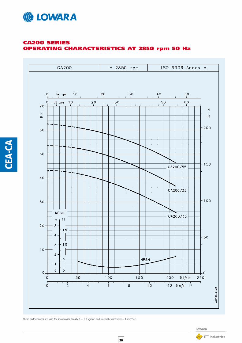
CA200 SERIESOPERATING CHARACTERISTICS AT 2850 rpm 50 Hz
These performances are valid for liquids with density ρ = 1.0 kg/dm3 and kinematic viscosity γ = 1 mm2/sec.
31
CEA-
CA
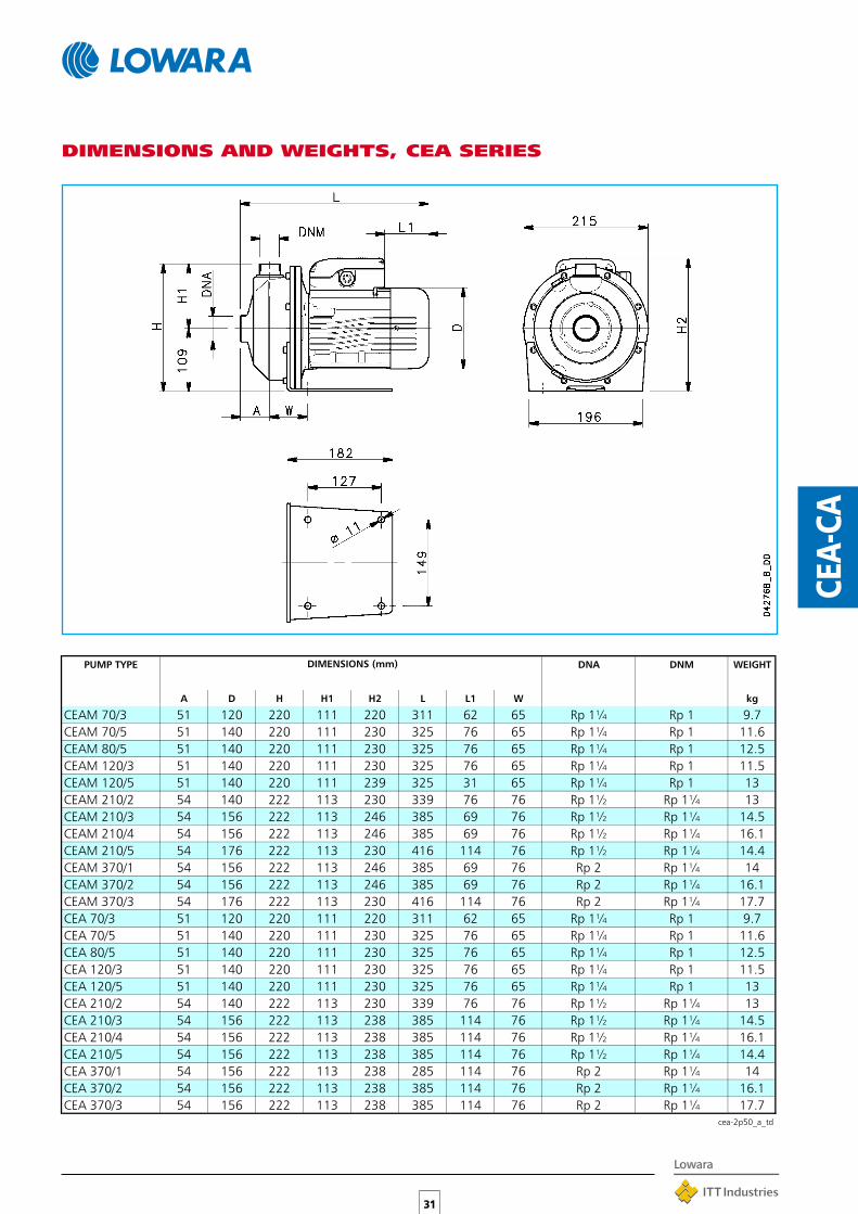
DIMENSIONS AND WEIGHTS, CEA SERIES
PUMP TYPE DNA DNM WEIGHT
A D H H1 H2 L L1 W kg
DIMENSIONS (mm)
CEAM 70/3 51 120 220 111 220 311 62 65 Rp 1¼ Rp 1 9.7
CEAM 70/5 51 140 220 111 230 325 76 65 Rp 1¼ Rp 1 11.6
CEAM 80/5 51 140 220 111 230 325 76 65 Rp 1¼ Rp 1 12.5
CEAM 120/3 51 140 220 111 230 325 76 65 Rp 1¼ Rp 1 11.5
CEAM 120/5 51 140 220 111 239 325 31 65 Rp 1¼ Rp 1 13
CEAM 210/2 54 140 222 113 230 339 76 76 Rp 1½ Rp 1¼ 13
CEAM 210/3 54 156 222 113 246 385 69 76 Rp 1½ Rp 1¼ 14.5
CEAM 210/4 54 156 222 113 246 385 69 76 Rp 1½ Rp 1¼ 16.1
CEAM 210/5 54 176 222 113 230 416 114 76 Rp 1½ Rp 1¼ 14.4
CEAM 370/1 54 156 222 113 246 385 69 76 Rp 2 Rp 1¼ 14
CEAM 370/2 54 156 222 113 246 385 69 76 Rp 2 Rp 1¼ 16.1
CEAM 370/3 54 176 222 113 230 416 114 76 Rp 2 Rp 1¼ 17.7
CEA 70/3 51 120 220 111 220 311 62 65 Rp 1¼ Rp 1 9.7
CEA 70/5 51 140 220 111 230 325 76 65 Rp 1¼ Rp 1 11.6
CEA 80/5 51 140 220 111 230 325 76 65 Rp 1¼ Rp 1 12.5
CEA 120/3 51 140 220 111 230 325 76 65 Rp 1¼ Rp 1 11.5
CEA 120/5 51 140 220 111 230 325 76 65 Rp 1¼ Rp 1 13
CEA 210/2 54 140 222 113 230 339 76 76 Rp 1½ Rp 1¼ 13
CEA 210/3 54 156 222 113 238 385 114 76 Rp 1½ Rp 1¼ 14.5
CEA 210/4 54 156 222 113 238 385 114 76 Rp 1½ Rp 1¼ 16.1
CEA 210/5 54 156 222 113 238 385 114 76 Rp 1½ Rp 1¼ 14.4
CEA 370/1 54 156 222 113 238 285 114 76 Rp 2 Rp 1¼ 14
CEA 370/2 54 156 222 113 238 385 114 76 Rp 2 Rp 1¼ 16.1
CEA 370/3 54 156 222 113 238 385 114 76 Rp 2 Rp 1¼ 17.7cea-2p50_a_td

32
CEA-
CA
DIMENSIONS AND WEIGHTS, CA SERIES
PUMP TYPE DNA DNM WEIGHT
D H L L1 M M1 N N1 S S1 W kg
DIMENSIONS (mm)
CAM 70/33 140 226 383 76 90 113 112 135 12 7 66 Rp 1¼ Rp 1 15
CAM 70/34 140 235 383 31 90 113 112 135 12 7 66 Rp 1¼ Rp 1 15.8
CAM 70/45 156 242 420 69 100 125 125 153 12 9 76 Rp 1¼ Rp 1 18.5
CAM 120/33 156 242 420 69 100 125 125 153 12 9 76 Rp 1¼ Rp 1 18.4
CAM 120/35 156 242 420 69 100 125 125 153 12 9 76 Rp 1¼ Rp 1 20.2
CAM 120/55 176 226 450 114 125 156 140 170 13 9 98 Rp 1¼ Rp 1 24.5
CAM 200/33 176 226 450 114 125 156 140 170 13 9 98 Rp 1½ Rp 1 24.2
CA 70/33 140 226 383 76 90 113 112 135 12 7 66 Rp 1¼ Rp 1 14.9
CA 70/34 140 226 383 76 90 113 112 135 12 7 66 Rp 1¼ Rp 1 15.7
CA 70/35 156 234 420 114 100 125 125 153 12 9 76 Rp 1¼ Rp 1 17
CA 120/33 156 234 420 114 100 125 125 153 12 9 76 Rp 1¼ Rp 1 16.8
CA120/35 156 234 420 114 100 125 125 153 12 9 76 Rp 1¼ Rp 1 18.7
CA 120/55 156 234 420 114 100 125 125 153 12 9 76 Rp 1¼ Rp 1 20.3
CA 200/33 156 234 420 114 100 125 125 153 12 9 76 Rp 1½ Rp 1 20
CA 200/35 176 226 450 149 125 156 140 170 13 9 98 Rp 1½ Rp 1 22.3
CA 200/55 176 226 450 149 125 156 140 170 13 9 98 Rp 1½ Rp 1 24.3
ca-2p50_a_td

33
CO
TABLE OF MATERIALS
CO SERIESTHREADED CENTRIFUGALPUMPS WITH OPEN IMPELLERThese pumps combine the advantages of anopen impeller with those of the AISI 316stainless steel construction, which is particularlysuited for handling moderately aggressive liquidswith suspended solids.
❏ ALL COMPONENTS IN CONTACT WITHPUMPED LIQUID ARE MADE OF AISI 316LSTAINLESS STEEL
❏ MECHANICAL SEAL MADE OF SILICONCARBIDE/SILICON CARBIDE/FPM IN THE“K” VERSION
APPLICATIONS•Washing and surface treatment of metal parts.
•Washing of foodstuffs, produce, fish and shellfish.
•Oil and cleaner circulation systems.
•Machine tool cooling fluid circulation systems.
•Commercial dishwashers.
•Industrial washing machines.
SPECIFICATIONS•Open impeller handles solids up to 20 mm
in diameter (10 mm for CO350 seriespumps).
•Delivery up to 900 l/min (54m3/h).
•Head up to 24 m.
•Maximum operating pressure: 8 bar.
•Continuous duty.
•Temperature of pumped liquid: -10°C to+110°C.
•Enclosed motor with external ventilation and aluminiumalloy finned casing.
•Versions:Single-phase 220-240 V 50 Hz, permanentlyconnected capacitor and built-in automatic reset overloadprotection up to 1,5 kW (except for 2,2 kW version).Three-phase 220-240/380-415 V 50 Hz, overloadprotection to be provided by user.
•Power up to 3 kW.
•Class F Insulation.
• IP 55 protection.
PART MATERIAL
Pump body, Flange, STAINLESS STEELSeal-housing disk, Impeller (AISI 316L - DIN 1.4404)
Shaft extension, STAINLESS STEELFill and drain plugs (AISI 316 - DIN 1.4401)
Standard mechanical seal CARBON/CERAMIC/FPM
“K” version mechanical seal SILICON CARBIDE/SILICON CARBIDE/FPM
O-rings seals FPM
* Bare shaft version available* 2 and 4 poles motor available

PUMP TYPE
l/min 0 100 120 160 200 240 280 300 350 375 400 450 500 600 650 700 800 900
m3/h 0 6 7.2 9.6 12 14.4 16.8 18 21 22.5 24 27 30 36 39 42 48 54
kW HP H = TOTAL HEAD METERS COLUMN OF WATER
Q = DELIVERY RATED
POWER
34
CO
CO350 SERIESHYDRAULIC PERFORMANCE TABLE AT 2850 rpm 50 Hz
CO(M) 350/03 0.37 0.5 9.5 6.8 6.3 5.5 4.8 4.1 3.4 3.0
CO(M) 350/05 0.55 0.75 12.0 9.2 8.8 7.9 7.1 6.3 5.5 5.1 4.0
CO(M) 350/07 0.75 1 13.7 11.2 10.8 9.9 9.1 8.2 7.4 6.9 5.8 5.3
CO(M) 350/09 0.9 1.2 15.7 12.7 12.2 11.3 10.5 9.6 8.8 8.3 7.2 6.6 5.9
CO(M) 350/11 1.1 0.5 17.3 14.3 13.8 12.9 12.0 11.2 10.5 10.1 9.1 8.6 8.0 6.8
CO(M) 350/15 1.5 2 20.3 16.9 16.4 15.3 14.4 13.5 12.7 12.2 11.2 10.6 10.0 8.7 7.2
CO(M) 500/15 1.5 2 16.0 13.4 12.8 12.3 12.0 11.3 10.9 10.5 9.8 9.0 7.4 6.6 5.8
CO(M) 500/22 2.2 3 19.6 17.3 16.7 16.2 15.9 15.2 14.9 14.5 13.7 13.0 11.3 10.4 9.6 7.7
CO 500/30 3 4 24.1 20.9 20.3 19.3 19.3 18.5 18.1 17.7 16.9 16.0 14.3 13.5 12.6 10.8 9.0
co-2p50_b_th
PUMP TYPE INPUT INPUT CAPACITOR PUMP TYPE
POWER* CURRENT*
220-240 V
A
220-240 V 380-415 V
kW µF / 450 V kW A A
220-240 V THREE-PHASE 220-240 V 380-415 V
kW A µF / 450 V kW A A
SINGLE-PHASE
INPUT
POWER*
INPUT
CURRENT*
INPUT
CURRENT*
COM350/03 0.63 2.82 14 C0 350/03 0.64 2.53 1.46
COM350/05 0.88 4.25 16 CO 350/05 0.79 2.7 1.56
COM350/07 1.02 4.67 20 C0 350/07 1 3.57 2.06
COM350/09 1.21 5.46 25 CO 350/09 1.13 4.21 2.43
COM350/11 1.75 7.85 30 C0 350/11 1.69 5.2 3
COM350/15 2.04 9.21 40 CO 350/15 1.98 6.3 3.64
COM500/15 2.02 9.12 40 C0 500/15 1.96 6.27 3.62
COM500/22 2.71 12.1 50 CO 500/22 2.73 9.06 5.23
- - - - C0 500/30 3.97 11.7 6.78
*Valori massimi nel campo di funzionamento co-2p50_b_te* Maximum value in specified range

35
CO
CO350 SERIESHYDRAULIC PERFORMANCE TABLE AT 2850 rpm 50 Hz
These performances are valid for liquids with density ρ = 1.0 kg/dm3 and kinematic viscosity γ = 1 mm2/sec.

36
CO
CO500 SERIESOPERATING CHARACTERISTICS AT 2850 rpm 50 Hz
These performances are valid for liquids with density ρ = 1.0 kg/dm3 and kinematic viscosity γ = 1 mm2/sec.

37
CO
DIMENSIONS AND WEIGHTS, CO SERIES
PUMP TYPE WEIGHT
kg
DNMDIMENSIONS (mm)
D H2 L L1
DNA
COM 350/03 10
COM 350/05 11.9
COM 350/07 12.6
COM 350/09 13.2
COM 350/11 14.5
COM 350/15 16.2
COM 500/15 16.2
COM 500/22 17.8
CO 350/03 10
CO 350/05 11.9
CO 350/07 12.6
CO 350/09 12.2
CO 350/11 14.5
CO 350/15 16.2
CO 500/15 16.2
CO 500/22 17.8
CO 500/30 22
co-2p50_a_td
Rp 1¼
Rp 1½
Rp 1½
Rp 1½
Rp 1¼
Rp 1¼
Rp 1¼
Rp 1¼
Rp 1¼
Rp 1¼
Rp 2
Rp 1½
Rp 1½
Rp 1½
Rp 1½
Rp 1½
Rp 1½
Rp 2
62
76
69
Rp 1¼
Rp 1¼
76
31
Rp 1¼
Rp 1¼
Rp 1¼
149
114
Rp 1½
114
Rp 2
Rp 2
76
Rp 1½
76
69
114
62 Rp 1½
76 Rp 1½
140
69
156
156
156
176
120
140
156
339
385
416
385
385
239
246
230
385
176
140
140
156
156
246
246
230
230
230
238
220
230
238
238
325
416
339
339
120
230
325
339
220
140
140 339230
385
339
156 385 114 Rp 1½
Rp 1½
238 385 114 Rp 2 Rp 1½
Rp 1½

Pump body CAST IRONImpeller 32, 40, 50, 65-125 STAINLESS STEEL (AISI 316 - DIN 1.4404)Impeller 65-160, 65-200,
CAST IRON65-250, 80, 100, 125, 150Adapter ALUMINIUM OR CAST IRONMechanical seal* CERAMIC/CARBON/NBR up to DN 80
CARBON/SILICON CARBIDE/EPDMfor 65-315, 80-315, 100,125, 150
O-ring seals NBRWear ring,Counterwear ring STAINLESS STEEL(only for DN32-80 (AISI 316L - DIN 1.4404)except for 65-315 and 80-315)Shaft STAINLESS STEEL AISI 316 L
for DN 32-80 (except for 65-315 and 80-135)STAINLESS STEEL AISI 420
for 65-315, 80-315, 100, 125, 150Support body (FHF) CAST IRON (200 - UNI ISO 185)Fill and drain plugs NICKEL-PLATED BRASS
APPLICATIONS•Water circulation and transfer in civil, industrial and
agricultural sectors.
•Pressure boosting.
•Water supply.
•Circulation of hot and cold water in heating andconditioning systems.
•Industrial washing.
•Water display, fountains.
AVAILABLE MODELS•FHE close-coupled with special motor shaft extension.
•FHS with stub shaft and standard motor.
•FHF with flexible coupling, base and standard motor incompliance with EN 733 - (ex DIN 24255).
SPECIFICATIONS•Maximum delivery up to 500 m3/h.•Maximum head up to 95 m.•Wear ring in stainless steel AISI 316 up to DN80 (except
65-315 and 80-315).
•Mechanical seal lubricated with the pumped liquidthrough a recirculation channel up to DN 80 (except 65-315 and 80-315).
•Nominal diameter of ports up to 150 mm.•Nominal diameter of impeller up to 315 mm.•2-pole single-phase motors up to 2.2 kW.
•2 and 4-pole three-phase motors.
•50 and 60 Hz frequencies.
•Counterflanges available on request.
•IP55 protection.
•Class F insulation.
•Maximum operating pressure: 12 bar.•Temperature of liquid from -10°C to +85°C for
versions up to DN 80 (from -20°C to +120°C forversions with EPDM elastomers) from -10°C to +120°Cfor 65-315, 80-315 and for DN 100, 125, 150.
•Versions with HYDROVAR frequencyconverter (variable speed) are available onrequest.
(1) Impeller in cast iron for some models of DN 65 and DN80, and DN 100, 125, 150.
38
FH
TABLE OF MATERIALS
PART MATERIAL
* -20°C a 120°C version: Ceramic / Carbon / EPDM
FH SERIESCENTRIFUGAL ELECTRICPUMPS IN COMPLIANCE WITHEN 733 - (ex DIN 24255)Cast iron pump body and AISI 316L stainlesssteel, laser-technology welded impeller (1).Suitable for pumping hot and cold, moderatelyaggressive liquids.
FH E 4 32 - 200 / 40 6 A
IDENTIFICATION CODE
Reduced impeller
6 = 60 Hz
Rated motor power(kW x 10)
Impeller nominal diameter(mm)
Discharge port nominaldiameter (mm)
4 = 4-pole motor
E =close-coupled versionS =Version with rigid coupling,
IEC normalised motorF =Version with flexible
coupling, support incompliance with EN 733
FH series name

39
FH
ELECTRICAL SPECIFICATIONS OF MOTORSWITH SPECIAL SHAFT EXTENSION, FHE SERIES
THREE-PHASE 50 Hz 2-POLES MOTORS
THREE-PHASE 50 Hz 4-POLES MOTORS
SINGLE-PHASE 50 Hz 2-POLES MOTORS
INPUT
CURRENT
In (A) Cn
kW 220-240 V µF V rpm ls / ln n % cosϕ Nm Cs/Cn
DATA FOR 230 V 50 Hz CAPACITOR
IEC
SIZE *
CONSTRUCTION
DESIGN
MOTOR TYPE
0.75 90R B14 5.02-5.39 30 450 2875 5.1 70.6 0.91 2.49 0.71
1.1 90R B14 7.07-6.81 30 450 2800 3.80 73.8 0.95 3.75 0.47
1.5 90R B14 9.32-8.63 40 450 2780 3.45 75.5 0.97 5.15 0.47
2.2 90 B14 13.3-12.6 50 450 2785 3.45 76.9 0.97 7.54 0.36
* R = Grandezza cassa motore ridotta rispetto alla sporgenza albero e relativa flangia. fhe-motm-2p50_a_te
IEC
SIZE *
CONSTRUCTION
DESIGN
∆ Y ∆ Y Cn
kW 220-240 V 380-415 V 380-415 V 660-690 V rpm ls / ln n % cosϕ Nm Cs/Cn
MOTOR TYPE INPUT CURRENT
In (A)
DATA FOR 400 V 50 Hz
0.75 90R B14 3.72 2.15 - - 2915 8.23 77.7 0.65 2.45 5.20
1.1 90R B14 4.52 2.61 - - 2875 6.78 78.9 0.77 3.65 3.49
1.5 90R B14 5.98 3.45 - - 2875 7.04 80.1 0.78 4.98 3.83
2.2 90R B14 8.71 5.03 - - 2860 7.32 81.1 0.78 7.34 4.12
3 90 B14 10.8 6.22 - - 2845 6.81 80.4 0.87 10.1 3.00
4 112R B14 - - 8.14 4.70 2900 7.86 83.5 0.85 13.2 2.86
5.5 112 B14 - - 11.0 6.35 2910 7.71 84.5 0.85 18.0 2.66
7.5 112 B14 - - 14.6 8.43 2910 7.62 87.2 0.85 24.6 3.03
9.2 132 B14 - - 17.5 10.1 2925 8.72 86.3 0.88 30.0 3.33
11 132 B14 - - 21.2 12.2 2925 8.75 88.8 0.84 35.9 3.66
15 160 B34 - - 28.6 16.5 2940 8.56 85.3 0.89 48.7 3.10
18.5 160 B34 - - 34.2 19.7 2945 8.80 87.3 0.90 60.0 4.06
22 160 B34 - - 40.3 23.3 2945 8.61 89.5 0.88 71.2 4.79
* R = Grandezza cassa motore ridotta rispetto alla sporgenza albero e relativa flangia. fhe-mott-2p50_a_te
IEC
SIZE *
CONSTRUCTION
DESIGN
∆ Y ∆ Y Cn
kW 220-240 V 380-415 V 380-415 V 660-690 V rpm ls / ln n % cosϕ Nm Cs/Cn
MOTOR TYPE INPUT CURRENT
In (A)
DATA FOR 400 V 50 Hz
0.25 71 B5 1.71 0.99 - - 1390 3.58 62.0 0.59 1.71 3.16
0.37 71 B5 2.53 1.46 - - 1370 3.39 61.4 0.60 2.57 3.40
0.55 90R B14 3.03 1.75 - - 1390 3.95 68.2 0.67 3.77 2.45
0.75 90R B5 4.04 2.33 - - 1395 4.06 70.1 0.66 5.13 2.73
1.1 90 B5 4.35 2.51 - - 1415 4.65 78.0 0.81 7.42 2.15
1.5 90 B5 5.85 3.38 - - 1420 4.99 79.9 0.80 10.1 2.26
2.2 100 B5 8.28 4.78 - - 1410 5.53 81.4 0.82 14.9 2.52
3 100 B5 11.0 6.37 - - 1425 6.03 82.5 0.82 20.1 2.53
4 112 B5 - - 8.38 4.84 1440 5.81 84.8 0.81 26.5 2.50
5.5 132 B14 - - 11.3 6.52 1445 5.98 85.8 0.82 36.3 2.60
7.5 132 B14 - - 15.2 8.78 1450 6.70 88.1 0.81 49.3 3.17
* R = Grandezza cassa motore ridotta rispetto alla sporgenza albero e relativa flangia. fhe-mott-4p50_a_te
* R = Reduced size of motor casing as compared to shaft extension and flange.
* R = Reduced size of motor casing as compared to shaft extension and flange.
* R = Reduced size of motor casing as compared to shaft extension and flange.

40
FH
STANDARD MOTOR ELECTRICAL SPECIFICATIONSFHS - FHF SERIES
THREE-PHASE 50 Hz 2-POLES MOTORS
THREE-PHASE 50 Hz 4-POLES MOTORS
∆ Y ∆ Y Cn
kW FHS FHF 220-240 V 380-415 V 380-415 V 660-690 V rpm ls / ln n % cosϕ Nm Cs/Cn
In (A)
IEC
SIZE *
CONSTRUCTION
DESIGN
MOTOR TYPE INPUT CURRENT DATA FOR 400 V 50 Hz
0.75 80R B5 - 3.50 2.02 - - 2855 5.81 74.3 0.72 2.51 3.76
0.75 80 - B3 3.72 2.15 - - 2915 8.23 77.7 0.65 2.45 5.20
1.1 80 B5 B3 4.52 2.61 - - 2875 6.78 78.9 0.77 3.65 3.49
1.5 90R B5 - 5.98 3.45 - - 2875 7.04 80.1 0.78 4.98 3.83
1.5 90 - B3 5.66 3.27 - - 2875 6.40 76.5 0.87 4.98 2.71
2.2 90R B5 - 8.71 5.03 - - 2860 7.32 81.1 0.78 7.34 4.12
2.2 90 - B3 8.02 4.63 - - 2870 6.94 80.0 0.86 7.32 2.85
3 100R B5 - 10.8 6.22 - - 2845 6.81 80.4 0.87 10.1 3.00
3 100 - B3 10.6 6.10 - - 2895 6.53 83.6 0.85 9.89 3.34
4 112R B5 - - - 8.14 4.70 2900 7.86 83.5 0.85 13.2 2.86
4 112 - B3 - - 8.21 4.74 2915 7.41 82.2 0.86 13.1 2.58
5.5 132R B5 - - - 11.0 6.35 2910 7.71 84.5 0.85 18.0 2.66
5.5 132 - B3 - - 10.7 6.18 2905 6.53 84.4 0.88 18.1 2.39
7.5 132R B5 - - - 14.6 8.43 2910 7.62 87.2 0.85 24.6 3.03
7.5 132 - B3 - - 14.4 8.31 2915 7.37 85.8 0.88 24.6 2.69
11 160 B35 B3 - - 21.6 12.5 2925 6.83 82.4 0.89 35.9 2.97
15 160 B35 B3 - - 28.6 16.5 2940 8.56 85.3 0.89 48.7 3.10
18.5 160 B35 B3 - - 34.2 19.7 2945 8.80 87.3 0.90 60.0 4.06
22 180R B35 - - - 40.3 23.3 2945 8.61 89.5 0.88 71.2 4.79
22 180 - B3 - - 42.0 24.2 2930 7.10 90.0 0.84 71.0 2.50
30 200 B35 B3 - - 55.0 31.8 2945 6.80 90.5 0.87 97.0 2.40
37 200 B35 B3 - - 67.0 38.7 2940 7.20 91.5 0.87 120 2.50
45 225 B35 B3 - - 81.0 46.8 2955 6.70 91.3 0.88 145 2.40
55 250 B35 B3 - - 98.0 56.6 2960 6.70 92.1 0.88 177 2.40
* R = Grandezza cassa motore ridotta rispetto alla sporgenza albero e relativa flangia. fhs-fhf-mott-2p50_a_te
∆ Y ∆ Y Cn
kW FHS FHF 220-240 V 380-415 V 380-415 V 660-690 V rpm ls / ln n % cosϕ Nm Cs/Cn
In (A)
IEC
SIZE *
CONSTRUCTION
DESIGN
MOTOR TYPE INPUT CURRENT DATA FOR 400 V 50 Hz
0.25 71 - B3 1.71 0.99 - - 1390 3.58 62.0 0.59 1.71 3.16
0.37 71 - B3 2.53 1.46 - - 1370 3.39 61.4 0.6 2.57 3.40
0.55 80 B5 B3 3.03 1.75 - - 1390 3.95 68.2 0.67 3.77 2.45
0.75 80 B5 B3 4.04 2.33 - - 1395 4.06 70.1 0.66 5.13 2.73
1.1 90 B5 B3 4.35 2.51 - - 1415 4.65 78.0 0.81 7.42 2.15
1.5 90 B5 B3 5.85 3.38 - - 1420 4.99 79.9 0.8 10.1 2.26
2.2 100 B5 B3 8.28 4.78 - - 1410 5.53 81.4 0.82 14.9 2.52
3 100 B5 B3 11.0 6.37 - - 1425 6.03 82.5 0.82 20.1 2.53
4 112 B5 B3 - - 8.38 4.84 1440 5.81 84.8 0.81 26.5 2.50
5.5 132 B5 B3 - - 11.3 6.52 1445 5.98 85.8 0.82 36.3 2.60
7.5 132 B5 B3 - - 15.2 8.78 1450 6.70 88.1 0.81 49.3 3.17
11 160 B5 - - - 22.5 13.0 1460 5.20 87.0 0.81 72.0 2.00
15 160 B5 - - - 30.4 17.6 1460 5.90 88.0 0.81 96.0 2.30
18.5 180 B5 - - - 37.1 21.4 1465 6.20 88.0 0.82 120 2.30
22 180 B5 - - - 42.6 24.6 1465 6.30 89.0 0.84 143 2.40
30 200 B5 - - - 57.3 33.1 1465 6.60 90.0 0.84 195 2.40
* R = Grandezza cassa motore ridotta rispetto alla sporgenza albero e relativa flangia. fhs-fhf-mott-4p50_a_te
* R = Reduced size of motor casing as compared to shaft extension and flange.
* R = Reduced size of motor casing as compared to shaft extension and flange.

32-125/07* 0,75 1 16,9 15,8 14,6 13 11 8,732-125/11* 1,1 1,5 21,9 20,7 19,6 18,1 16,3 14,2 932-160/15* 1,5 2 27,3 25,9 24,5 22,7 20,5 17,8 1132-160/22* 2,2 3 34,7 33,3 32 30,2 28 25,3 18,832-200/30 3 4 44,2 41,5 39,8 37,7 35,2 32,2 24,632-200/40 4 5,5 54,4 52 50 47,7 45 41,9 34,6 2632-250/55 5,5 7,5 79 74,7 71 67 62 55,6 3732-250/75 7,5 10 99 95,3 92 88 83 76 58,340-125/11* 1,1 1,5 14,5 13,7 13 11,3 8,8 5,840-125/15* 1,5 2 18,1 17,2 16,7 15 12,7 9,6 640-125/22* 2,2 3 24,5 23,5 23 21 18,8 15,8 12,3 8,240-160/30 3 4 31,5 30 29,5 27,5 24,5 21,5 17,440-160/40 4 5,5 38 37 36 34 31,5 28,5 24,5 2040-200/55 5,5 7,5 46,5 45 44 41,5 38,5 34,5 29,540-200/75 7,5 10 57 55 54 52 49 45,5 41 3640-250/** 11 15 64 60 59 56 53 49 45 3940-250/110 11 15 72 68 67 65 61 57 52 4740-250/150 15 20 85 81 80 77 74 70 65 6050-125/22* 2,2 3 17 16 15,1 14 12,8 9,8 6,250-125/30 3 4 20 19,5 18,8 18 16,9 14,1 10,550-125/40 4 5,5 24 23,5 23 22,5 21,5 19 15,8 11,850-160/55 5,5 7,5 32 31,5 30,5 29,5 28 24,5 20,5 14,850-160/75 7,5 10 40 39 38 37 36 33 29 2450-200/** 11 15 50,5 48 47 45 43 38,5 32,5 25,550-200/110 11 15 58 55 54 53 50 46 40 3350-250/150 15 20 68 65 64 63 61 56 50 4150-250/185 18,5 25 77 74 73 72 70 66 60 5250-250/220 22 30 86 84 83 81 80 75 70 61 5165-125/40 4 5,5 19 17,5 16 14,5 13 1165-125/55 5,5 7,5 23 21,5 20,5 19 17,5 16 1465-125/75 7,5 10 27 26 25 24,5 23 22 20 1865-160/** 11 15 33 32 31 30 28 26 24 21,565-160/110 11 15 36 35 34 33 31,5 30 28 25,565-160/150 15 20 42 41,5 41 40 38,5 37 35 33 29,565-200/150 15 20 45 46 45 43 41 39 36,5 3465-200/185 18,5 25 52 53 52 51 49 47 44,5 4265-200/220 22 30 59 60 59 58 56 54 52 49,5 44,565-250/200 22 30 62 62 60 58 55,5 52 48,5 44 36,565-250/300 30 40 76 75 74 73 70,5 67,5 64 61 5465-250/370 37 50 90 88,5 87 86 84 81 78 74,5 68,580-160/110 11 15 27 27,5 27 26 24,5 22,5 21 1680-160/150 15 20 33 33 32 31 30 28 26 2280-160/185 18,5 25 39 38,5 37,5 36,5 35,5 34 32,5 28,5 2280-200/220 22 30 48 47,5 46,5 45 43,5 41 38,5 32,580-200/300 30 40 60 60 59 58 57 54,5 52 47 3980-250/370 37 50 71 71 69 67 65 61 58 4980-250/450 45 61 80 81 80 78 76 72,5 70 6280-250/550 55 75 92 94 93 91 89,5 86,5 84 77 66100-160/220 22 30 33,3 31,8 31 30,3 28,2 25,5 20,3 15,3100-160/300 30 40 43 40,8 40 39,2 37,2 34,7 29,3 23,7 16100-200/300 30 40 49,5 47 45,8 44,7 41,5 37,3 29,3 20100-200/370 37 50 56 54,3 53,3 52,4 49,8 45,8 38 29,5
41
FH
FHE - FHS - FHF SERIESHYDRAULIC PERFORMANCE TABLE 50 Hz, 2 POLES
PUMP TYPE POWER
kW HP
Q = DELIVERY
100 150 200 250 300 400 500 600 700 800 1000 1200 1400 1600 1800 2000 2300 2500 3000 3600 4500 5300 6200
6 9 12 15 18 24 30 36 42 48 60 72 84 96 108 120 138 150 180 216 270 318 372
H = TOTAL HEAD METERS COLUMN OF WATER
l/min 0
m3/h 0
* * / 92 - 9,2 kW - 12,5 HP - FHE / 110A - 11 kW - 15 HP - FHS-FHF
*single-phase version (FHEM) also available

32-125/02A 0,25 0,33 4,4 4,2 3,9 3,5 3,1 2,5 1,932-125/02 0,25 0,33 5,5 5,2 5 4,7 4,3 3,8 3,1 2,432-160/02 0,25 0,33 6,5 6,1 5,8 5,4 4,9 4,3 3,6 2,832-160/03 0,37 0,5 8,5 8 7,7 7,3 6,9 6,3 5,7 4,932-200/03 0,37 0,5 9,9 9,2 8,7 8,1 7,4 6,7 5,9 532-200/05 0,55 0,75 12,5 11,9 11,3 10,7 10,1 9,3 8,4 7,5 5,432-250/07 0,75 1 19,4 18,5 17,7 16,7 15,5 13,8 11,7 932-250/11 1,1 1,5 22,5 21,6 20,8 19,9 18,6 17 15 12,540-125/02A 0,25 0,33 4 3,9 3,8 3,6 3,4 2,9 2,240-125/02 0,25 0,33 5,1 4,9 4,7 4,5 4,3 3,8 3,140-125/03 0,37 0,5 6,3 6 5,8 5,6 5,4 4,9 4,2 2,340-160/03 0,37 0,5 7,4 6,9 6,7 6,4 6,1 5,4 4,640-160/05 0,55 0,75 9,1 8,7 8,5 8,2 7,9 7,2 6,3 4,340-200/07 0,75 1 11,6 11 10,8 10,5 10,2 9,4 8,440-200/11 1,1 1,5 14,1 13,4 13,2 12,9 12,6 11,8 10,8 8,340-250/11 1,1 1,5 15 14 13,7 13,3 13 12,2 11,2 8,540-250/15 1,5 2 17,5 16,5 16,2 15,8 15,5 14,6 13,5 10,840-250/22 2,2 3 21 19,7 19,3 19 18,5 17,6 16,6 14 10,640-125/03A 0,37 0,5 4,3 4,2 4,1 3,9 3,4 2,7 1,850-125/03 0,37 0,5 5 4,8 4,6 4,4 3,9 3,3 2,450-125/05 0,55 0,75 5,9 5,8 5,7 5,5 5,1 4,4 3,550-160/07 0,75 1 7,9 7,8 7,6 7,4 6,8 5,8 4,750-160/11 1,1 1,5 9,7 9,5 9,3 9,1 8,5 7,6 6,550-200/11 1,1 1,5 12,1 11,6 11,3 10,9 9,9 8,6 7,150-200/15 1,5 2 13,9 13,3 13 12,6 11,6 10,2 8,650-250/22A 2,2 3 16,5 16,2 16 15,6 14,6 13,2 11,450-250/22 2,2 3 18,6 18 17,8 17,4 16,5 15,2 13,450-250/30 3 4 21 20,5 20,3 20 19 17,8 16,2 11,865-125/05 0,55 0,75 4,6 4,1 3,8 3,4 2,565-125/07 0,75 1 5,6 5,1 4,9 4,5 3,7 2,665-125/11 1,1 1,5 6,6 6,3 6,1 5,9 5,2 4,265-160/11 1,1 1,5 8 7,6 7,3 7 6 4,8 3,465-160/15 1,5 2 8,8 8,5 8,3 8 7,1 6 4,665-160/22 2,2 3 10,3 10,1 9,8 9,5 8,8 7,8 6,5 565-200/15 1,5 2 10 10 9,6 9,1 7,9 6,4 4,665-200/22 2,2 3 12,4 12,5 12,2 11,8 10,7 9,3 7,665-200/30 3 4 14,4 14,5 14,3 13,8 12,7 11,3 9,6 7,565-250/30 3 4 15,4 15 14,6 13,9 12 9,7 6,765-250/40 4 5,5 19 18,8 18,3 17,8 15,7 14,4 11,765-250/50 5,5 7,5 22,3 21,7 21,3 20,9 19,5 17,7 15,1 1265-315/75 7,5 10 30,8 30 29,8 28,8 27,6 25,8 23,3 19,765-315/110 11 15 36,2 35,7 35,5 34,7 33,5 31,8 29,8 31,8 23
42
FH
FHE - FHS - FHF SERIESHYDRAULIC PERFORMANCE TABLE 50 Hz, 4 POLES
PUMP TYPE POWER
kW HP
Q = DELIVERY
l/min 0 50 75 100 125 150 175 200 250 300 400 500 600 800 1000 1200 1400 1600 1800m3/h 0 3 4,5 6 7,5 9 10,5 12 15 18 24 30 36 48 60 72 84 96 108
H = TOTAL HEAD METERS COLUMN OF WATER
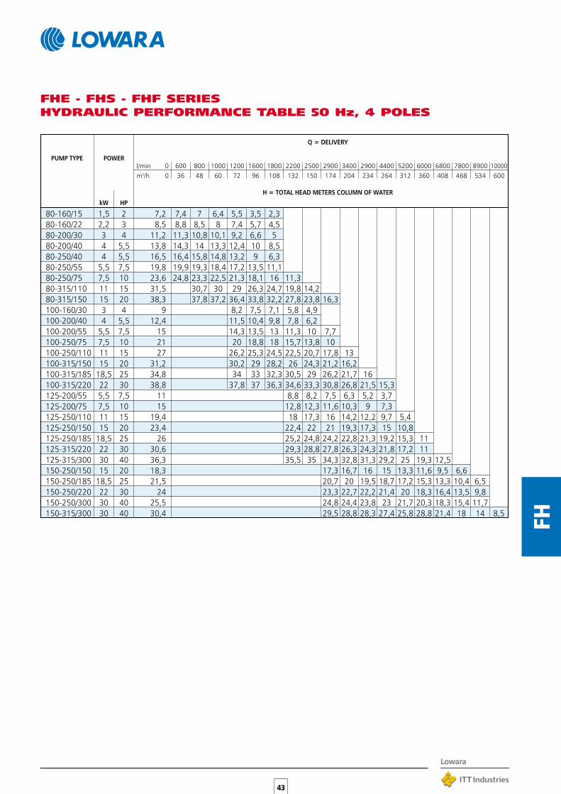
80-160/15 1,5 2 7,2 7,4 7 6,4 5,5 3,5 2,380-160/22 2,2 3 8,5 8,8 8,5 8 7,4 5,7 4,580-200/30 3 4 11,2 11,3 10,8 10,1 9,2 6,6 580-200/40 4 5,5 13,8 14,3 14 13,3 12,4 10 8,580-250/40 4 5,5 16,5 16,4 15,8 14,8 13,2 9 6,380-250/55 5,5 7,5 19,8 19,9 19,3 18,4 17,2 13,5 11,180-250/75 7,5 10 23,6 24,8 23,3 22,5 21,3 18,1 16 11,380-315/110 11 15 31,5 30,7 30 29 26,3 24,7 19,8 14,280-315/150 15 20 38,3 37,8 37,2 36,4 33,8 32,2 27,8 23,8 16,3100-160/30 3 4 9 8,2 7,5 7,1 5,8 4,9100-200/40 4 5,5 12,4 11,5 10,4 9,8 7,8 6,2100-200/55 5,5 7,5 15 14,3 13,5 13 11,3 10 7,7100-250/75 7,5 10 21 20 18,8 18 15,7 13,8 10100-250/110 11 15 27 26,2 25,3 24,5 22,5 20,7 17,8 13100-315/150 15 20 31,2 30,2 29 28,2 26 24,3 21,2 16,2100-315/185 18,5 25 34,8 34 33 32,3 30,5 29 26,2 21,7 16100-315/220 22 30 38,8 37,8 37 36,3 34,6 33,3 30,8 26,8 21,5 15,3125-200/55 5,5 7,5 11 8,8 8,2 7,5 6,3 5,2 3,7125-200/75 7,5 10 15 12,8 12,3 11,6 10,3 9 7,3125-250/110 11 15 19,4 18 17,3 16 14,2 12,2 9,7 5,4125-250/150 15 20 23,4 22,4 22 21 19,3 17,3 15 10,8125-250/185 18,5 25 26 25,2 24,8 24,2 22,8 21,3 19,2 15,3 11125-315/220 22 30 30,6 29,3 28,8 27,8 26,3 24,3 21,8 17,2 11125-315/300 30 40 36,3 35,5 35 34,3 32,8 31,3 29,2 25 19,3 12,5150-250/150 15 20 18,3 17,3 16,7 16 15 13,3 11,6 9,5 6,6150-250/185 18,5 25 21,5 20,7 20 19,5 18,7 17,2 15,3 13,3 10,4 6,5150-250/220 22 30 24 23,3 22,7 22,2 21,4 20 18,3 16,4 13,5 9,8150-250/300 30 40 25,5 24,8 24,4 23,8 23 21,7 20,3 18,3 15,4 11,7150-315/300 30 40 30,4 29,5 28,8 28,3 27,4 25,8 28,8 21,4 18 14 8,5
43
FH
FHE - FHS - FHF SERIESHYDRAULIC PERFORMANCE TABLE 50 Hz, 4 POLES
PUMP TYPE POWER
kW HP
Q = DELIVERY
l/min 0 600 800 1000 1200 1600 1800 2200 2500 2900 3400 2900 4400 5200 6000 6800 7800 8900 10000m3/h 0 36 48 60 72 96 108 132 150 174 204 234 264 312 360 408 468 534 600
H = TOTAL HEAD METERS COLUMN OF WATER

44
FH
FH 32 SERIESOPERATING CHARACTERISTICS at 2900 rpm 50 Hz, 2 POLES
Please verify with the price list the availability of model type FHE-FHS-FHF
These performances are valid for liquids with density ρ = 1.0 kg/dm3 and kinematic viscosity γ = 1 mm2/sec.
*
*
* 2FHE Version
*
*

45
FH
FH 40 SERIESOPERATING CHARACTERISTICS at 2900 rpm 50 Hz, 2 POLES
Please verify with the price list the availability of model type FHE-FHS-FHF
These performances are valid for liquids with density ρ = 1.0 kg/dm3 and kinematic viscosity γ = 1 mm2/sec.
** /92 - 9,2 - 12,5HP for version FHE – /110A - 11kW - 15HP for version FHS-FHF
46
FH
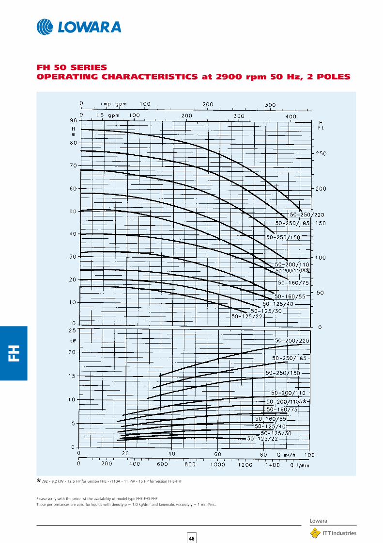
FH 50 SERIESOPERATING CHARACTERISTICS at 2900 rpm 50 Hz, 2 POLES
Please verify with the price list the availability of model type FHE-FHS-FHF
These performances are valid for liquids with density ρ = 1.0 kg/dm3 and kinematic viscosity γ = 1 mm2/sec.
* /92 - 9,2 kW - 12,5 HP for version FHE - /110A - 11 kW - 15 HP for version FHS-FHF
*
*

47
FH
FH 65 SERIESOPERATING CHARACTERISTICS at 2900 rpm 50 Hz, 2 POLES
Please verify with the price list the availability of model type FHE-FHS-FHF
These performances are valid for liquids with density ρ = 1.0 kg/dm3 and kinematic viscosity γ = 1 mm2/sec.
* /92 - 9,2 kW - 12,5 HP for version FHE - /110A - 11 kW - 15 HP for version FHS-FHF
*
*

48
FH
FH 80 SERIESOPERATING CHARACTERISTICS at 2900 rpm 50 Hz, 2 POLES
Please verify with the price list the availability of model type FHE-FHS-FHF
These performances are valid for liquids with density ρ = 1.0 kg/dm3 and kinematic viscosity γ = 1 mm2/sec.

49
FH
FH 100 SERIESOPERATING CHARACTERISTICS at 2900 rpm 50 Hz, 2 POLES
Please verify with the price list the availability of model type FHE-FHS-FHF
These performances are valid for liquids with density ρ = 1.0 kg/dm3 and kinematic viscosity γ = 1 mm2/sec.

50
FH
FH4 32 SERIESOPERATING CHARACTERISTICS at 1450 rpm 50 Hz, 4 POLES
Please verify with the price list the availability of model type FHE-FHS-FHF
These performances are valid for liquids with density ρ = 1.0 kg/dm3 and kinematic viscosity γ = 1 mm2/sec.
* Version 2FHE4
**
*
*

51
FH
FH4 40 SERIESOPERATING CHARACTERISTICS at 1450 rpm 50 Hz, 4 POLES
Please verify with the price list the availability of model type FHE-FHS-FHF
These performances are valid for liquids with density ρ = 1.0 kg/dm3 and kinematic viscosity γ = 1 mm2/sec.

52
FH
FH4 50 SERIESOPERATING CHARACTERISTICS at 1450 rpm 50 Hz, 4 POLES
Please verify with the price list the availability of model type FHE-FHS-FHF
These performances are valid for liquids with density ρ = 1.0 kg/dm3 and kinematic viscosity γ = 1 mm2/sec.
53
FH
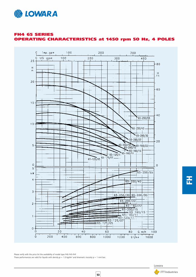
FH4 65 SERIESOPERATING CHARACTERISTICS at 1450 rpm 50 Hz, 4 POLES
Please verify with the price list the availability of model type FHE-FHS-FHF
These performances are valid for liquids with density ρ = 1.0 kg/dm3 and kinematic viscosity γ = 1 mm2/sec.

54
FH
FH4 65 - 315 SERIESOPERATING CHARACTERISTICS at 1450 rpm 50 Hz, 4 POLES
Please verify with the price list the availability of model type FHE-FHS-FHF
These performances are valid for liquids with density ρ = 1.0 kg/dm3 and kinematic viscosity γ = 1 mm2/sec.

55
FH
FH4 80 SERIESOPERATING CHARACTERISTICS at 1450 rpm 50 Hz, 4 POLES
Please verify with the price list the availability of model type FHE-FHS-FHF
These performances are valid for liquids with density ρ = 1.0 kg/dm3 and kinematic viscosity γ = 1 mm2/sec.

56
FH
FH4 80 - 315 SERIESOPERATING CHARACTERISTICS at 1450 rpm 50 Hz, 4 POLES
Please verify with the price list the availability of model type FHE-FHS-FHF
These performances are valid for liquids with density ρ = 1.0 kg/dm3 and kinematic viscosity γ = 1 mm2/sec.

57
FH
FH4 100 SERIESOPERATING CHARACTERISTICS at 1450 rpm 50 Hz, 4 POLES
Please verify with the price list the availability of model type FHE-FHS-FHF
These performances are valid for liquids with density ρ = 1.0 kg/dm3 and kinematic viscosity γ = 1 mm2/sec.

58
FH
FH4 125 SERIESOPERATING CHARACTERISTICS at 1450 rpm 50 Hz, 4 POLES
Please verify with the price list the availability of model type FHE-FHS-FHF
These performances are valid for liquids with density ρ = 1.0 kg/dm3 and kinematic viscosity γ = 1 mm2/sec.

59
FH
FH4 150 SERIESOPERATING CHARACTERISTICS at 1450 rpm 50 Hz, 4 POLES
Please verify with the price list the availability of model type FHE-FHS-FHF
These performances are valid for liquids with density ρ = 1.0 kg/dm3 and kinematic viscosity γ = 1 mm2/sec.

60
FH
CLEARANCE FOR DISASSEMBLY
G3/8 FILL
G3/8 DRAIN
FHE WITH SUPPORT UNDER MOTOR15 TO 22 kW MOTORS
FLANGES
DN D M GHOLES MAX.
N° Ø THICKNESS
80 200 160 138 8 18 22
100 220 180 158 8 18 22
PUMP TYPE PUMP SUPPORT B H L k WEIGHTDNM DNA a h2 w x b c c1 h1 m m1 n n1 s s1 max. kg
FHE 32-125/07 32 50 80 140 235 129 50 12 – 112 100 70 190 140 14 – 233 252 443 86 27FHE 32-125/11 32 50 80 140 235 129 50 12 – 112 100 70 190 140 14 – 233 252 443 86 28FHE 32-160/15 32 50 80 160 235 129 50 12 – 132 100 70 240 190 14 – 235 292 443 86 31FHE 32-160/22 32 50 80 160 235 129 50 12 – 132 100 70 240 190 14 – 235 292 443 86 34FHE 32-200/30 32 50 80 180 283 121 50 12 – 160 100 70 240 190 14 – 285 340 461 86 43FHE 32-200/40 32 50 80 180 290 133 50 12 – 160 100 70 240 190 14 – 285 340 487 86 49FHE 40-125/11 40 65 80 140 235 129 50 12 – 112 100 70 210 160 14 – 233 252 443 88 30FHE 40-125/15 40 65 80 140 235 129 50 12 – 112 100 70 210 160 14 – 233 252 443 88 31FHE 40-125/22 40 65 80 140 235 129 50 12 – 112 100 70 210 160 14 – 233 252 443 88 33FHE 40-160/30 40 65 80 160 283 121 50 12 – 132 100 70 240 190 14 – 250 292 461 88 36FHE 40-160/40 40 65 80 160 290 133 50 12 – 132 100 70 240 190 14 – 250 292 487 88 42FHE 40-200/55 40 65 100 180 311 150 50 12 – 160 100 70 265 212 14 – 285 340 553 88 59FHE 40-200/75 40 65 100 180 311 150 50 12 – 160 100 70 265 212 14 – 285 340 553 88 64FHE 40-250/92 40 65 100 225 278 191 65 14 – 180 125 95 320 250 14 – 335 405 604 107 91FHE 40-250/110 40 65 100 225 278 191 65 14 – 180 125 95 320 250 14 – 335 405 604 107 99FHE 40-250/150 40 65 100 225 208 232 50 22 20 180 260 210 318 254 13 23 335 412 688 107 123FHE 50-125/22 50 65 100 160 235 129 50 12 – 132 100 70 240 190 14 – 255 292 463 92 37FHE 50-125/30 50 65 100 160 285 121 50 12 – 132 100 70 240 190 14 – 255 292 481 92 39FHE 50-125/40 50 65 100 160 292 133 50 12 – 132 100 70 240 190 14 – 255 292 507 92 45FHE 50-160/55 50 65 100 180 313 150 50 12 – 160 100 70 265 212 14 – 285 340 553 92 68FHE 50-160/75 50 65 100 180 313 150 50 12 – 160 100 70 265 212 14 – 285 340 553 92 72FHE 50-200/92 50 65 100 200 280 191 50 12 – 160 100 70 265 212 14 – 305 360 604 92 81FHE 50-200/110 50 65 100 200 280 191 50 12 – 160 100 70 265 212 14 – 305 360 604 92 86FHE 50-250/150 50 65 100 225 208 232 50 22 20 180 260 210 318 254 13 23 340 412 688 107 123FHE 50-250/185 50 65 100 225 208 232 50 22 20 180 304 254 318 254 13 23 340 412 732 107 135FHE 50-250/220 50 65 100 225 208 232 50 22 20 180 304 254 318 254 13 23 340 412 732 107 149FHE 65-125/40 65 80 100 180 292 133 65 14 – 160 125 95 280 212 14 – 285 340 507 105 64FHE 65-125/55 65 80 100 180 313 150 65 14 – 160 125 95 280 212 14 – 285 340 553 105 72FHE 65-125/75 65 80 100 180 313 150 65 14 – 160 125 95 280 212 14 – 285 340 553 105 76FHE 65-160/92 65 80 100 200 278 191 65 14 – 160 125 95 280 212 14 – 331 360 604 112 95FHE 65-160/110 65 80 100 200 278 191 65 14 – 160 125 95 280 212 14 – 331 360 604 112 103FHE 65-160/150 65 80 100 200 208 232 50 22 – 160 260 210 318 254 13 23 331 392 688 112 127FHE 65-200/150 65 80 100 225 208 232 50 22 20 180 260 210 318 254 13 23 335 412 688 112 127FHE 65-200/185 65 80 100 225 208 232 50 22 20 180 304 254 318 254 13 23 335 412 732 112 139FHE 65-200/220 65 80 100 225 208 232 50 22 20 180 304 254 318 254 13 23 335 412 732 112 153FHE 65-250/220 65 80 100 250 208 232 50 22 40 200 304 254 318 254 13 23 332 450 732 112 159FHE 80-160/110 80 100 125 225 278 191 65 14 – 180 125 95 320 250 14 – 332 405 629 129 109FHE 80-160/150 80 100 125 225 208 232 50 22 20 180 260 210 318 254 13 23 332 412 713 129 133FHE 80-160/185 80 100 125 225 208 232 50 22 20 180 304 254 318 254 13 23 332 412 757 129 145FHE 80-200/220 80 100 125 250 208 232 50 22 20 180 304 254 318 254 13 23 332 430 757 129 159
DIMENSIONS AND WEIGHTS, FHE 2 POLES SERIES
FLANGES
DN D M GHOLES MAX.
N° Ø THICKNESS
32 140 100 78 4 18 18
40 150 110 88 4 18 18
50 165 125 102 4 18 20
65 185 145 122 4 18 20
FHE WITH SUPPORT FOOT ON PUMPMOTORS UP TO 11 kW
G3/8 FILL
G3/8 DRAINCLEARANCE FOR DISASSEMBLY

61
FH
DIMENSIONS AND WEIGHTS, 2FHE 2 POLES SERIES
PUMP TYPE WEIGHTkg
2FHE 32-250/55 712FHE 32-250/75 75
G 3/8 FILL
G 3/8 DRAIN

62
FH
FLANGES
DN D M GHOLES MAX.
N° Ø THICKNESS
32 140 100 78 4 18 18
40 150 110 88 4 18 18
50 165 125 102 4 18 20
65 185 145 122 4 18 20
FLANGES
DN D M GHOLES MAX.
N° Ø THICKNESS
80 200 160 138 8 18 22
100 220 180 158 8 18 22
PUMP TYPE PUMP SUPPORT B H L k WEIGHTDNM DNA a h2 w x b c h1 m m1 n n1 s max. kg
FHE4 32-125/02A 32 50 80 140 215 121 50 12 112 100 70 190 140 14 233 252 411 92 25FHE4 32-125/02 32 50 80 140 215 121 50 12 112 100 70 190 140 14 233 252 411 92 25FHE4 32-160/02 32 50 80 160 215 121 50 12 132 100 70 240 190 14 235 292 411 92 26FHE4 32-160/03 32 50 80 160 215 121 50 12 132 100 70 240 190 14 235 292 411 92 26FHE4 32-200/03 32 50 80 180 215 121 50 12 160 100 70 240 190 14 285 340 411 92 35FHE4 32-200/05 32 50 80 180 235 129 50 12 160 100 70 240 190 14 285 340 443 92 37FHE4 40-125/02A 40 65 80 140 215 121 50 12 112 100 70 210 160 14 233 252 411 94 25FHE4 40-125/02 40 65 80 140 215 121 50 12 112 100 70 210 160 14 233 252 411 94 25FHE4 40-125/03 40 65 80 140 215 121 50 12 112 100 70 210 160 14 233 252 411 94 25FHE4 40-160/03 40 65 80 160 215 121 50 12 132 100 70 240 190 14 250 292 411 94 27FHE4 40-160/05 40 65 80 160 235 129 50 12 132 100 70 240 190 14 250 292 443 94 29FHE4 40-200/07 40 65 100 180 235 129 50 12 160 100 70 265 212 14 285 340 463 94 38FHE4 40-200/11 40 65 100 180 283 121 50 12 160 100 70 265 212 14 285 340 481 94 42FHE4 40-250/11 40 65 100 225 283 121 65 14 180 125 95 320 250 14 335 405 481 113 52FHE4 40-250/15 40 65 100 225 283 121 65 14 180 125 95 320 250 14 335 405 481 113 55FHE4 40-250/22 40 65 100 225 290 133 65 14 180 125 95 320 250 14 335 405 507 113 59FHE4 50-125/03A 50 65 100 160 217 121 50 12 132 100 70 240 190 14 255 292 433 98 29FHE4 50-125/03 50 65 100 160 217 121 50 12 132 100 70 240 190 14 255 292 433 98 29FHE4 50-125/05 50 65 100 160 237 129 50 12 132 100 70 240 190 14 255 292 465 98 32FHE4 50-160/07 50 65 100 180 237 129 50 12 160 100 70 265 212 14 285 340 465 98 41FHE4 50-160/11 50 65 100 180 285 121 50 12 160 100 70 265 212 14 285 340 483 98 45FHE4 50-200/11 50 65 100 200 285 121 50 12 160 100 70 265 212 14 305 360 483 98 44FHE4 50-200/15 50 65 100 200 285 121 50 12 160 100 70 265 212 14 305 360 483 98 47FHE4 50-250/22A 50 65 100 225 290 133 65 14 180 125 95 320 250 14 340 405 507 113 59FHE4 50-250/22 50 65 100 225 290 133 65 14 180 125 95 320 250 14 340 405 507 113 59FHE4 50-250/30 50 65 100 225 290 133 65 14 180 125 95 320 250 14 340 405 507 113 62FHE4 65-125/05 65 80 100 180 237 129 65 14 160 125 95 280 212 14 285 340 465 108 45FHE4 65-125/07 65 80 100 180 237 129 65 14 160 125 95 280 212 14 285 340 465 108 45FHE4 65-125/11 65 80 100 180 265 121 65 14 160 125 95 280 212 14 285 340 483 108 49FHE4 65-160/11 65 80 100 200 283 121 65 14 160 125 95 280 212 14 331 360 481 117 56FHE4 65-160/15 65 80 100 200 283 121 65 14 160 125 95 280 212 14 331 360 481 117 59FHE4 65-160/22 65 80 100 200 290 133 65 14 160 125 95 280 212 14 331 360 507 117 63FHE4 65-200/15 65 80 100 225 283 121 65 14 180 125 95 320 250 14 335 405 481 117 59FHE4 65-200/22 65 80 100 225 290 133 65 14 180 125 95 320 250 14 335 405 507 117 63FHE4 65-200/30 65 80 100 225 290 133 65 14 180 125 95 320 250 14 335 405 507 117 65FHE4 65-250/30 65 80 100 250 290 133 80 16 200 160 120 360 280 18 360 450 507 125 75FHE4 65-250/40 65 80 100 250 311 151 80 16 200 160 120 360 280 18 360 450 530 125 105FHE4 65-250/55 65 80 100 250 259 191 80 16 200 160 120 360 280 18 360 450 566 125 111FHE4 80-160/15 80 100 125 225 283 121 65 14 180 125 95 320 250 14 332 405 506 132 64FHE4 80-160/22 80 100 125 225 290 133 65 14 180 125 95 320 250 14 332 405 532 132 69FHE4 80-200/30 80 100 125 250 290 133 65 14 180 125 95 345 280 14 345 430 532 132 80FHE4 80-200/40 80 100 125 250 311 151 65 14 180 125 95 345 280 14 345 430 555 132 103FHE4 80-250/40 80 100 125 280 311 151 80 16 200 160 120 400 315 18 400 480 555 132 100FHE4 80-250/55 80 100 125 280 259 191 80 16 200 160 120 400 315 18 400 480 591 132 106FHE4 80-250/75 80 100 125 280 278 191 80 16 200 160 120 400 315 18 400 480 629 132 116
DIMENSIONS AND WEIGHTS, FHE4 4 POLES SERIES
CLEARANCE FOR DISASSEMBLY
G3/8 FILL
G3/8 DRAIN

63
FH
PUMP TYPE WEIGHTkg
2FHE4 32-250/07 472FHE4 32-250/11 49
DIMENSIONS AND WEIGHTS, 2FHE4 4 POLES SERIES
G 3/8 FILL
G 3/8 DRAIN

64
FH
DIMENSIONS AND WEIGHTS, FHS 2 POLES SERIES
FLANGES
DN D M GHOLES MAX.
N° Ø THICKNESS
32 140 100 78 4 18 18
40 150 110 88 4 18 18
50 165 125 102 4 18 20
65 185 145 122 4 18 20
G3/8 FILL
G3/8 DRAINCLEARANCE FOR DISASSEMBLY
FHS WITH SUPPORT FOOT ON PUMPMOTORS UP TO 7,5 kW
FHS WITH SUPPORT UNDER MOTOR11 TO 55 kW MOTORS
G3/8 FILL
G3/8 DRAIN
SPAZIO PER LO SMONTAGGIO FLANGES
DN D M GHOLES MAX.
N° Ø THICKNESS
80 200 160 138 8 18 22
100 220 180 158 8 18 22
PUMP TYPE PUMP SUPPORT B H L k WEIGHTDNM DNA a f h2 w x b c c1 h1 m m1 n n1 s s1 max. kg
FHS 32-125/07 32 50 80 155 140 265 121 50 12 – 112 100 70 190 140 14 – 233 252 461FHS 32-125/11 32 50 80 155 140 290 129 50 12 – 112 100 70 190 140 14 – 233 252 498FHS 32-160/15 32 50 80 155 160 290 129 50 12 – 132 100 70 240 190 14 – 235 292 498FHS 32-160/22 32 50 80 155 160 290 129 50 12 – 132 100 70 240 190 14 – 235 292 498FHS 32-200/30 32 50 80 165 180 355 121 50 12 – 160 100 70 240 190 14 – 285 340 548FHS 32-200/40 32 50 80 165 180 355 133 50 12 – 160 100 70 240 190 14 – 285 340 552FHS 40-125/11 40 65 80 155 140 290 129 50 12 – 112 100 70 210 160 14 – 233 252 498FHS 40-125/15 40 65 80 155 140 290 129 50 12 – 112 100 70 210 160 14 – 233 252 498FHS 40-125/22 40 65 80 155 140 290 129 50 12 – 112 100 70 210 160 14 – 233 252 498FHS 40-160/30 40 65 80 165 160 355 121 50 12 – 132 100 70 240 190 14 – 250 292 548FHS 40-160/40 40 65 80 165 160 355 133 50 12 – 132 100 70 240 190 14 – 250 292 552FHS 40-200/55 40 65 100 192 180 424 150 50 12 – 160 100 70 265 212 14 – 300 340 666FHS 40-200/75 40 65 100 192 180 424 150 50 12 – 160 100 70 265 212 14 – 300 340 666FHS 40-250/110A 40 65 100 222 225 330 232 50 22 20 180 260 210 318 254 13 23 350 412 801FHS 40-250/110 40 65 100 222 225 330 232 50 22 20 180 260 210 318 254 13 23 350 412 801FHS 40-250/150 40 65 100 222 225 330 232 50 22 20 180 260 210 318 254 13 23 350 412 801FHS 50-125/22 50 65 100 157 160 292 129 50 12 – 132 100 70 240 190 14 – 255 292 520FHS 50-125/30 50 65 100 167 160 357 121 50 12 – 132 100 70 240 190 14 – 255 292 570FHS 50-125/40 50 65 100 167 160 357 133 50 12 – 132 100 70 240 190 14 – 255 292 574FHS 50-160/55 50 65 100 194 180 426 150 50 12 – 160 100 70 265 212 14 – 300 340 668FHS 50-160/75 50 65 100 194 180 426 150 50 12 – 160 100 70 265 212 14 – 300 340 668FHS 50-200/110A 50 65 100 224 200 332 232 50 22 – 160 260 210 318 254 13 23 350 392 812FHS 50-200/110 50 65 100 224 200 332 232 50 22 – 160 260 210 318 254 13 23 350 392 812FHS 50-250/150 50 65 100 222 225 330 232 50 22 20 180 260 210 318 254 13 23 350 412 810FHS 50-250/185 50 65 100 222 225 330 232 50 22 20 180 304 254 318 254 13 23 350 412 854FHS 50-250/220 50 65 100 222 225 330 232 50 22 20 180 304 254 318 254 13 23 350 412 854FHS 65-125/40 65 80 100 167 180 357 133 65 14 – 160 125 95 280 212 14 – 285 340 574FHS 65-125/55 65 80 100 194 180 426 150 65 14 – 160 125 95 280 212 14 – 300 340 668FHS 65-125/75 65 80 100 194 180 426 150 65 14 – 160 125 95 280 212 14 – 300 340 668FHS 65-160/110A 65 80 100 222 200 330 232 50 22 20 180 260 210 318 254 13 23 350 412 810FHS 65-160/110 65 80 100 222 200 330 232 50 22 20 180 260 210 318 254 13 23 350 412 810FHS 65-160/150 65 80 100 222 200 330 232 50 22 20 180 260 210 318 254 13 23 350 412 810FHS 65-200/150 65 80 100 222 225 330 232 50 22 20 180 260 210 318 254 13 23 350 412 810FHS 65-200/185 65 80 100 222 225 330 232 50 22 20 180 304 254 318 254 13 23 350 412 854FHS 65-200/220 65 80 100 222 225 330 232 50 22 20 180 304 254 318 254 13 23 350 412 854FHS 65-250/220 65 80 100 222 250 330 232 50 22 40 200 304 254 318 254 13 23 350 450 854FHS 65-250/300 65 80 100 228 250 361 257 60 24 – 200 345 305 360 318 18 18 400 457 941FHS 65-250/370 65 80 100 228 250 361 257 60 24 – 200 345 305 360 318 18 18 400 457 941FHS 80-160/110 80 100 125 222 225 330 232 50 22 20 180 260 210 318 254 13 23 350 412 835FHS 80-160/150 80 100 125 222 225 330 232 50 22 20 180 260 210 318 254 13 23 350 412 835FHS 80-160/185 80 100 125 222 225 330 232 50 22 20 180 304 254 318 254 13 23 350 412 879FHS 80-200/220 80 100 125 222 250 330 232 50 22 20 180 304 254 318 254 13 23 350 430 879FHS 80-200/300 80 100 125 228 250 361 257 60 24 – 200 345 305 360 318 18 18 400 457 966FHS 80-250/370 80 100 125 228 280 361 257 60 24 – 200 345 305 360 318 18 18 400 480 966FHS 80-250/450 80 100 125 228 280 377 280 76 28 – 225 360 311 405 356 18 18 450 505 1043FHS 80-250/550 80 100 125 258 280 426 280 90 28 – 250 406 349 465 406 22 22 550 530 1073
86 3286 3486 3586 3786 5186 6288 3488 3688 3988 4488 4588 7388 77107 119107 119107 13392 4392 4892 5692 7692 8092 11192 111107 133107 145107 159105 70105 80105 84112 123112 123112 137112 137112 149112 163112 157112 200112 218129 124129 138129 156129 163129 199129 213129 278129 311
65
FH
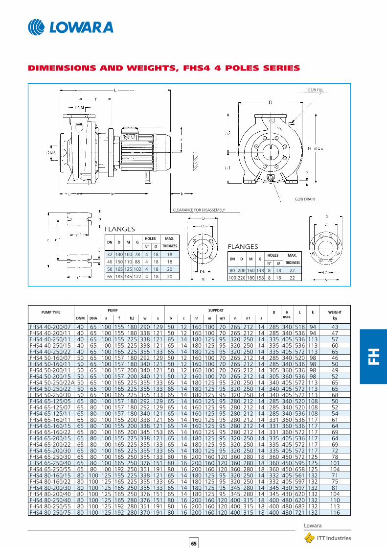
PUMP TYPE PUMP SUPPORT B H L k WEIGHTDNM DNA a f h2 w x b c h1 m m1 n n1 s max. kg
FHS4 40-200/07 40 65 100 155 180 290 129 50 12 160 100 70 265 212 14 285 340 518 94 43FHS4 40-200/11 40 65 100 155 180 338 121 50 12 160 100 70 265 212 14 285 340 536 94 47FHS4 40-250/11 40 65 100 155 225 338 121 65 14 180 125 95 320 250 14 335 405 536 113 57FHS4 40-250/15 40 65 100 155 225 338 121 65 14 180 125 95 320 250 14 335 405 536 113 60FHS4 40-250/22 40 65 100 165 225 355 133 65 14 180 125 95 320 250 14 335 405 572 113 65FHS4 50-160/07 50 65 100 157 180 292 129 50 12 160 100 70 265 212 14 285 340 520 98 46FHS4 50-160/11 50 65 100 157 180 340 121 50 12 160 100 70 265 212 14 285 340 536 98 50FHS4 50-200/11 50 65 100 157 200 340 121 50 12 160 100 70 265 212 14 305 360 536 98 49FHS4 50-200/15 50 65 100 157 200 340 121 50 12 160 100 70 265 212 14 305 360 536 98 52FHS4 50-250/22A 50 65 100 165 225 355 133 65 14 180 125 95 320 250 14 340 405 572 113 65FHS4 50-250/22 50 65 100 165 225 355 133 65 14 180 125 95 320 250 14 340 405 572 113 65FHS4 50-250/30 50 65 100 165 225 355 133 65 14 180 125 95 320 250 14 340 405 572 113 68FHS4 65-125/05 65 80 100 157 180 292 129 65 14 160 125 95 280 212 14 285 340 520 108 50FHS4 65-125/07 65 80 100 157 180 292 129 65 14 160 125 95 280 212 14 285 340 520 108 52FHS4 65-125/11 65 80 100 157 180 340 121 65 14 160 125 95 280 212 14 285 340 536 108 54FHS4 65-160/11 65 80 100 155 200 338 121 65 14 160 125 95 280 212 14 331 360 536 117 61FHS4 65-160/15 65 80 100 155 200 338 121 65 14 160 125 95 280 212 14 331 360 536 117 64FHS4 65-160/22 65 80 100 165 200 345 153 65 14 160 125 95 280 212 14 331 360 572 117 69FHS4 65-200/15 65 80 100 155 225 338 121 65 14 180 125 95 320 250 14 335 405 536 117 64FHS4 65-200/22 65 80 100 165 225 355 133 65 14 180 125 95 320 250 14 335 405 572 117 69FHS4 65-200/30 65 80 100 165 225 355 133 65 14 180 125 95 320 250 14 335 405 572 117 72FHS4 65-250/30 65 80 100 165 250 355 133 80 16 200 160 120 360 280 18 360 450 572 125 78FHS4 65-250/40 65 80 100 165 250 376 151 80 16 200 160 120 360 280 18 360 450 595 125 101FHS4 65-250/55 65 80 100 192 250 351 191 80 16 200 160 120 360 280 18 360 450 658 125 104FHS4 80-160/15 80 100 125 155 225 338 121 65 14 180 125 95 320 250 14 332 405 561 132 71FHS4 80-160/22 80 100 125 165 225 355 133 65 14 180 125 95 320 250 14 332 405 597 132 75FHS4 80-200/30 80 100 125 165 250 355 133 65 14 180 125 95 345 280 14 345 430 597 132 81FHS4 80-200/40 80 100 125 165 250 376 151 65 14 180 125 95 345 280 14 345 430 620 132 104FHS4 80-250/40 80 100 125 165 280 376 151 80 16 200 160 120 400 315 18 400 480 620 132 110FHS4 80-250/55 80 100 125 192 280 351 191 80 16 200 160 120 400 315 18 400 480 683 132 113FHS4 80-250/75 80 100 125 192 280 370 191 80 16 200 160 120 400 315 18 400 480 721 132 116
DIMENSIONS AND WEIGHTS, FHS4 4 POLES SERIES
FLANGES
DN D M GHOLES MAX.
N° Ø THICKNESS
32 140 100 78 4 18 18
40 150 110 88 4 18 18
50 165 125 102 4 18 20
65 185 145 122 4 18 20
G3/8 FILL
G3/8 DRAIN
CLEARANCE FOR DISASSEMBLY
FLANGES
DN D M GHOLES MAX.
N° Ø THICKNESS
80 200 160 138 8 18 22
100 220 180 158 8 18 22

PUMP TYPE PUMP SUPPORT B H L k WEIGHTDNM DNA a f h2 w x b b1 c h1 m m1 m2 n n1 s max. kg
FHS 100-160/220 100 125 125 226 280 78 232 45 48 14 215 137 91 23 240 200 14 411 495 883
FHS 100-160/300 100 125 125 231 280 92 257 – 65 20 250 300 235 32,5 300 250 18 435 530 969
FHS 100-200/300 100 125 125 231 280 92 257 – 65 20 250 300 235 32,5 300 250 18 405 530 969
FHS 100-200/370 100 125 125 231 280 92 257 – 65 20 250 300 235 32,5 300 250 18 405 530 969
66
FH
DIMENSIONS AND WEIGHTS, FHS 2 POLES SERIES
G3/8 FILL
G3/8 DRAIN
CLEARANCE FOR DISASSEMBLY
FLANGES
DN D M GHOLES MAX.
N° Ø THICKNESS
100 220 180 158 8 18 24
125 250 210 188 8 18 26
143 236
143 348
153 340
153 360

PUMP TYPE PUMP SUPPORT B H L k WEIGHTDNM DNA a f h2 w x b b1 c c1 h1 m m1 m2 n n1 s max. kg
FHS4 65-315/75 65 80 125 196 280 83 194 45 48 14 – 250 137 89 24 240 200 14 434 530 725FHS4 65-315/110 65 80 125 226 280 83 243 45 48 14 – 250 137 89 24 240 200 14 434 530 889FHS4 80-315/110 80 100 125 226 315 83 243 45 48 14 – 250 137 89 24 240 200 14 450 565 889FHS4 80-315/150 80 100 125 226 315 83 243 45 48 14 – 250 137 89 24 240 200 14 450 565 889FHS4 100-160/30 100 125 125 196 280 – 133 80 – 16 – 225 160 120 – 360 280 19 415 505 628FHS4 100-200/40 100 125 125 196 280 – 151 80 – 18 – 200 160 120 – 360 280 19 385 480 651FHS4 100-200/55 100 125 125 196 280 77 194 45 48 14 – 215 137 91 23 240 200 14 373 495 687FHS4 100-250/75 100 125 140 196 280 78 194 45 42 14 – 220 165 131 15 240 200 14 416 500 740FHS4 100-250/110 100 125 140 226 280 78 243 45 42 14 – 220 165 131 15 240 200 14 416 500 904FHS4 100-315/150 100 125 140 226 315 78 243 45 48 14 – 250 137 89 24 240 200 14 486 565 904FHS4 100-315/185 100 125 140 226 315 83 243 45 48 14 – 250 137 89 24 240 200 14 486 565 904FHS4 100-315/220 100 125 140 226 315 83 263 45 48 14 – 250 137 89 24 240 200 14 486 565 979FHS4 125-200/55 125 150 140 211 315 91 194 45 48 14 – 235 137 91 23 240 200 14 469 550 717FHS4 125-200/75 125 150 140 211 315 91 194 45 48 14 – 235 137 91 23 240 200 14 469 550 755FHS4 125-250/110 125 150 140 226 355 78 243 45 48 14 – 250 137 91 23 240 200 14 493 605 904FHS4 125-250/150 125 150 140 226 355 78 243 45 48 14 – 250 137 91 23 240 200 14 493 605 904FHS4 125-250/185 125 150 140 226 355 78 243 45 48 14 – 250 137 91 23 240 200 14 493 605 904FHS4 125-315/220 125 150 140 241 355 101 263 – 65 20 – 280 300 235 32,5 300 250 18 501 635 994FHS4 125-315/300 125 150 140 241 355 101 263 – 65 20 – 280 300 235 32,5 300 250 18 501 635 994FHS4 150-250/150 150 200 160 241 375 101 243 – 70 20 30 280 305 235 35 305 250 18 543 655 939FHS4 150-250/185 150 200 160 241 375 101 243 – 70 20 30 280 305 235 35 305 250 18 543 655 939FHS4 150-250/220 150 200 160 241 375 101 263 – 70 20 30 280 305 235 35 305 250 18 543 655 1014FHS4 150-250/300 150 200 160 241 375 101 263 – 70 20 30 280 305 235 35 305 250 18 543 655 1014FHS4 150-315/300 150 200 160 241 400 101 263 – 65 20 – 280 300 235 32,5 300 250 18 567 680 1014
67
FH
R 1/4 FILL
R 3/8 DRAIN
CLEARANCE
DIMENSIONS AND WEIGHTS, FHS4 4 POLES SERIES
FLANGES
DN D M GHOLES MAX.
N° Ø THICKNESS
65 185 145 122 4 18 22
80 200 160 138 8 18 22
100 220 180 158 8 18 24
125 250 210 188 8 18 26
150 285 240 212 8 22 26
200 340 295 268 8 22 26
160 168160 212160 218160 238143 110153 106153 131150 171150 215160 247160 282160 292160 162160 175158 217158 237158 273171 344171 429181 300181 335181 345181 430186 448
FOR DISASSEMBLY
R 3/8 DRAIN
CLEARANCE FOR DISASSEMBLY
R 1/4 FILL
3÷4 kW
5,5÷30 kW

68
FH
PUMP TYPE DIMENSIONS(mm) s WEIGHTDNM DNA a B1 B2 L1 L2 L3 G M h1 h2 H max. FOR SCREWS kg
FHF 32-125/07 32 50 80 320 360 744 540 800 130 60 212 140 352 M16 67FHF 32-125/11 32 50 80 320 360 744 540 800 130 60 212 140 352 M16 69FHF 32-160/15 32 50 80 350 390 773 600 900 150 60 232 160 392 M16 71FHF 32-160/22 32 50 80 350 390 773 600 900 150 60 232 160 392 M16 73FHF 32-200/30 32 50 80 350 390 809 600 900 150 60 260 180 440 M16 92FHF 32-200/40 32 50 80 350 390 832 600 900 150 60 260 180 440 M16 96FHF 40-125/11 40 65 80 320 360 744 540 800 130 60 212 140 352 M16 72FHF 40-125/15 40 65 80 350 390 773 600 900 150 60 212 140 352 M16 74FHF 40-125/22 40 65 80 350 390 773 600 900 150 60 212 140 352 M16 77FHF 40-160/30 40 65 80 350 390 809 600 900 150 60 232 160 392 M16 91FHF 40-160/40 40 65 80 350 390 832 600 900 150 60 232 160 392 M16 97FHF 40-200/55 40 65 100 400 450 909 660 1000 170 60 260 180 451 M20 112FHF 40-200/75 40 65 100 400 450 909 660 1000 170 60 260 180 451 M20 120FHF 40-250/110A 40 65 100 490 540 1061 840 1250 205 75 280 225 512 M20 178FHF 40-250/110 40 65 100 490 540 1061 840 1250 205 75 280 225 512 M20 178FHF 40-250/150 40 65 100 490 540 1061 840 1250 205 75 280 225 512 M20 188FHF 50-125/22 50 65 100 350 390 793 600 900 150 60 232 160 392 M16 85FHF 50-125/30 50 65 100 350 390 829 600 900 150 60 232 160 392 M16 92FHF 50-125/40 50 65 100 350 390 852 600 900 150 60 232 160 392 M16 97FHF 50-160/55 50 65 100 400 450 909 660 1000 170 60 260 180 451 M20 111FHF 50-160/75 50 65 100 400 450 909 660 1000 170 60 260 180 451 M20 115FHF 50-200/110A 50 65 100 440 490 1061 740 1120 190 60 260 200 492 M20 173FHF 50-200/110 50 65 100 440 490 1061 740 1120 190 60 260 200 492 M20 173FHF 50-250/150 50 65 100 490 540 1061 840 1250 205 75 280 225 512 M20 179FHF 50-250/185 50 65 100 490 540 1105 840 1250 205 75 280 225 512 M20 199FHF 50-250/220 50 65 100 490 540 1111 840 1250 205 75 280 225 510 M20 219FHF 65-125/40 65 80 100 350 390 852 600 900 150 75 260 180 440 M16 135FHF 65-125/55 65 80 100 400 450 909 660 1000 170 75 260 180 451 M20 141FHF 65-125/75 65 80 100 400 450 909 660 1000 170 75 260 180 451 M20 147FHF 65-160/110A 65 80 100 490 540 1061 840 1250 205 75 260 200 492 M20 164FHF 65-160/110 65 80 100 490 540 1061 840 1250 205 75 260 200 492 M20 164FHF 65-160/150 65 80 100 490 540 1061 840 1250 205 75 260 200 492 M20 180FHF 65-200/150 65 80 100 490 540 1061 840 1250 205 75 280 225 512 M20 187FHF 65-200/185 65 80 100 490 540 1105 840 1250 205 75 280 225 512 M20 197FHF 65-200/220 65 80 100 490 540 1111 840 1250 205 75 280 225 510 M20 215FHF 65-250/220 65 80 100 490 540 1221 840 1250 205 90 310 250 550 M20 223FHF 65-250/300 65 80 100 550 610 1296 940 1400 230 90 310 250 557 M24 300FHF 65-250/370 65 80 100 550 610 1296 940 1400 230 90 310 250 557 M24 315FHF 80-160/110 80 100 125 490 540 1086 840 1250 205 75 280 225 512 M20 202FHF 80-160/150 80 100 125 490 540 1086 840 1250 205 75 280 225 512 M20 212FHF 80-160/185 80 100 125 490 540 1130 840 1250 205 75 280 225 512 M20 233FHF 80-200/220 80 100 125 490 540 1246 840 1250 205 75 280 250 530 M20 245FHF 80-200/300 80 100 125 550 610 1321 940 1400 230 75 310 250 557 M24 285FHF 80-250/370 80 100 125 550 610 1321 940 1400 230 90 310 280 580 M24 305FHF 80-250/450 80 100 125 550 610 1398 940 1400 230 90 365 280 605 M24 365FHF 80-250/550 80 100 125 600 660 1428 1060 1600 270 90 390 280 660 M24 400
DIMENSIONS AND WEIGHTS, FHF 2 POLES SERIES
G3/8 FILL
G3/8 DRAIN

69
FH
DIMENSIONS AND WEIGHTS, FHF4 4 POLES SERIES
G3/8 FILL
G3/8 DRAIN
PUMP TYPE DIMENSIONS(mm) s WEIGHTDNM DNA a B1 B2 L1 L2 L3 G M h1 h2 H max. FOR SCREWS kg
FHF4 32-125/02A 32 50 80 320 360 702 540 800 130 60 212 140 352 M16 74FHF4 32-125/02 32 50 80 320 360 702 540 800 130 60 212 140 352 M16 74FHF4 32-160/02 32 50 80 320 360 702 540 800 130 60 232 160 392 M16 76FHF4 32-160/03 32 50 80 320 360 702 540 800 130 60 232 160 392 M16 78FHF4 32-200/03 32 50 80 320 360 702 540 800 130 60 260 180 440 M16 80FHF4 32-200/05 32 50 80 320 360 744 540 800 130 60 260 180 440 M16 82FHF4 40-125/02A 40 65 80 320 360 702 540 800 130 60 212 140 352 M16 61FHF4 40-125/02 40 65 80 320 360 702 540 800 130 60 212 140 352 M16 61FHF4 40-125/03 40 65 80 320 360 702 540 800 130 60 212 140 352 M16 64FHF4 40-160/03 40 65 80 320 360 702 540 800 130 60 232 160 392 M16 65FHF4 40-160/05 40 65 80 320 360 744 540 800 130 60 232 160 392 M16 66FHF4 40-200/07 40 65 100 350 390 764 600 900 150 60 260 180 440 M16 73FHF4 40-200/11 40 65 100 350 390 793 600 900 150 60 260 180 440 M16 76FHF4 40-250/11 40 65 100 400 450 793 660 1000 170 75 280 225 505 M20 103FHF4 40-250/15 40 65 100 400 450 793 660 1000 170 75 280 225 505 M20 106FHF4 40-250/22 40 65 100 400 450 829 660 1000 170 75 280 225 505 M20 119FHF4 50-125/03A 50 65 100 320 360 722 540 800 130 60 232 160 392 M16 64FHF4 50-125/03 50 65 100 320 360 722 540 800 130 60 232 160 392 M16 64FHF4 50-125/05 50 65 100 320 360 764 540 800 130 60 232 160 392 M16 66FHF4 50-160/07 50 65 100 350 390 764 600 900 150 60 260 180 440 M16 73FHF4 50-160/11 50 65 100 350 390 793 600 900 150 60 260 180 440 M16 76FHF4 50-200/11 50 65 100 350 390 793 600 900 150 60 260 200 460 M16 87FHF4 50-200/15 50 65 100 350 390 793 600 900 150 60 260 200 460 M16 90FHF4 50/250/22A 50 65 100 400 450 829 660 1000 170 75 280 225 505 M20 121FHF4 50-250/22 50 65 100 400 450 829 660 1000 170 75 280 225 505 M20 121FHF4 50-250/30 50 65 100 400 450 829 660 1000 170 75 280 225 505 M20 125FHF4 65-125/05 65 80 100 350 390 764 600 900 150 75 260 180 440 M16 90FHF4 65-125/07 65 80 100 350 390 764 600 900 150 75 260 180 440 M16 91FHF4 65-125/11 65 80 100 350 390 793 600 900 150 75 260 180 440 M16 95FHF4 65-160/11 65 80 100 400 450 793 660 1000 170 75 260 200 460 M20 100FHF4 65-160/15 65 80 100 400 450 793 660 1000 170 75 260 200 460 M20 110FHF4 65-160/22 65 80 100 400 450 829 660 1000 170 75 260 200 460 M20 119FHF4 65-200/15 65 80 100 400 450 793 660 1000 170 75 280 225 505 M20 112FHF4 65-200/22 65 80 100 440 490 829 740 1120 190 75 280 225 505 M20 123FHF4 65-200/30 65 80 100 440 490 829 740 1120 190 75 280 225 505 M20 126FHF4 65-250/30 65 80 100 440 490 939 740 1120 190 90 310 250 550 M20 150FHF4 65-250/40 65 80 100 440 490 962 740 1120 190 90 310 250 550 M20 162FHF4 65-250/55 65 80 100 440 490 1019 740 1120 190 90 310 250 550 M20 180FHF4 80-160/15 80 100 125 400 450 818 660 1000 170 75 280 228 505 M20 130FHF4 80-160/22 80 100 125 440 490 854 740 1120 190 75 280 228 505 M20 136FHF4 80-200/30 80 100 125 440 490 964 740 1120 190 75 280 250 530 M20 155FHF4 80-200/40 80 100 125 440 490 987 740 1120 190 75 280 250 530 M20 159FHF4 80-250/40 80 100 125 490 540 987 840 1250 205 90 310 280 580 M20 165FHF4 80-250/55 80 100 125 490 540 1044 840 1250 205 90 310 280 580 M20 180FHF4 80-250/75 80 100 125 490 540 1082 840 1250 205 90 310 280 580 M20 193

70
SH
APPLICATIONS•Water circulation and transfer in the civil, industrial and
agricultural markets.
•Industrial washing.
•Pressure boosting.
•Hot and cold water circulation for heating andconditioning systems.
AVAILABLE MODELS•SHE close-coupled with special motor shaft extension.
•SHS with stub shaft and standard motor.
•SHF with flexible coupling, base and standard motor incompliance with EN 733 - (ex DIN 24255).
•SSH 25-125, 160, 200, 250 on request.
SPECIFICATIONS•Maximum delivery up to 240 m3/h.
•Maximum head up to 110 m.
•316L stainless steel, laser-welded impeller(up to 65-160 size) and pump body.
•AISI 316L stainless steel wear rings.
•Port nominal diameter up to DN 80.
• Impeller nominal diameter up to 250 mm.
•2- and 4-pole three-phase motors.
•50 and 60 Hz frequencies.
•Counterflanges available on request.
•IP55 protection.
•Class F insulation.
•Maximum operating pressure: 12 bar (PN12).
•Pumped liquid temperature -10°C to +110°C.
•Versions with HYDROVAR frequencyconverter (variable speed) are available onrequest.
SH SERIESCENTRIFUGAL PUMPSMANUFACTURED IN AISI 316STAINLESS STEEL INCOMPLIANCE WITHEN 733 - (ex DIN 24255)Laser-technology welded centrifugal pumps.Designed to handle hot, cold and moderatelyaggressive liquids.
Pump body,Seal housing, Impeller STAINLESS STEELWear ring AISI 316L - DIN 1.4404Counterwear ringAdapter ALUMINIUM OR
DIN GG20 CAST IRONMechanical seal CERAMIC/CARBON/FPMO-Ring FPMFill/drain plugs STAINLESS STEEL
AISI 316L-DIN 1.4404Shaft (SHE - SHF), STAINLESS STEELCoupling (SHS) AISI 316 - DIN 1.4401Support body (SHF) DIN GG20 CAST IRON
TABLE OF MATERIALS
PART MATERIAL
SH E 4 32 - 200 / 40 6 A
IDENTIFICATION CODE
Reduced impeller
6 = 60 Hz
Rated motor power(kW x 10)
Impeller nominal diameter(mm)
Delivery port nominaldiameter (mm)
4 = 4-pole motor
E =Close-coupled versionS =Version with rigid coupling,
IEC normalised motorF =Version with flexible
coupling, support incompliance with EN 733
SH Series name

71
SH
ELECTRICAL SPECIFICATIONSMOTORS WITH EXTENDED SHAFT FOR SHE SERIES
SINGLE-PHASE 50 Hz 2 POLES MOTORS
THREE-PHASE 50 Hz 2 POLES MOTORS
THREE-PHASE 50 Hz 4 POLES MOTORS
INPUT
CURRENT
In (A) Cn
kW 220-240 V µF V rpm ls / ln n % cosϕ Nm Cs/Cn
DATA FOR 230 V 50 Hz CAPACITOR
IEC
SIZE *
CONSTRUCTION
DESIGN
MOTOR TYPE
1.1 90R B14 7.07-6.81 30 450 2800 3.80 73.8 0.95 3.75 0.47
* R = Grandezza cassa motore ridotta rispetto alla sporgenza albero e relativa flangia. she-motm-2p50_a_te
IEC
SIZE *
CONSTRUCTION
DESIGN
∆ Y ∆ Y Cn
kW 220-240 V 380-415 V 380-415 V 660-690 V rpm ls / ln n % cosϕ Nm Cs/Cn
MOTOR TYPE INPUT CURRENT
In (A)
DATA FOR 400 V 50 Hz
0.75 90R B14 3.72 2.15 - - 2915 8.23 77.7 0.65 2.45 5.20
1.1 90R B14 4.52 2.61 - - 2875 6.78 78.9 0.77 3.65 3.49
1.5 90R B14 5.98 3.45 - - 2875 7.04 80.1 0.78 4.98 3.83
2.2 90R B14 8.71 5.03 - - 2860 7.32 81.1 0.78 7.34 4.12
3 90 B14 10.8 6.22 - - 2845 6.81 80.4 0.87 10.1 3.00
4 112R B14 - - 8.14 4.70 2900 7.86 83.5 0.85 13.2 2.86
5.5 112 B14 - - 11.0 6.35 2910 7.71 84.5 0.85 18.0 2.66
7.5 112 B14 - - 14.6 8.43 2910 7.62 87.2 0.85 24.6 3.03
9.2 132 B14 - - 17.5 10.1 2925 8.72 86.3 0.88 30.0 3.33
11 132 B14 - - 21.2 12.2 2925 8.75 88.8 0.84 35.9 3.66
15 160 B34 - - 28.6 16.5 2940 8.56 85.3 0.89 48.7 3.10
18.5 160 B34 - - 34.2 19.7 2945 8.80 87.3 0.90 60.0 4.06
22 160 B34 - - 40.3 23.3 2945 8.61 89.5 0.88 71.2 4.79
* R = Grandezza cassa motore ridotta rispetto alla sporgenza albero e relativa flangia. she-mott-2p50_a_te
IEC
SIZE *
CONSTRUCTION
DESIGN
∆ Y ∆ Y Cn
kW 220-240 V 380-415 V 380-415 V 660-690 V rpm ls / ln n % cosϕ Nm Cs/Cn
MOTOR TYPE INPUT CURRENT
In (A)
DATA FOR 400 V 50 Hz
0.25 71 B5 1.71 0.99 - - 1390 3.58 62.0 0.59 1.71 3.16
0.37 71 B5 2.53 1.46 - - 1370 3.39 61.4 0.60 2.57 3.40
0.55 90R B14 3.03 1.75 - - 1390 3.95 68.2 0.67 3.77 2.45
0.75 90R B5 4.04 2.33 - - 1395 4.06 70.1 0.66 5.13 2.73
1.1 90 B5 4.35 2.51 - - 1415 4.65 78.0 0.81 7.42 2.15
1.5 90 B5 5.85 3.38 - - 1420 4.99 79.9 0.80 10.1 2.26
2.2 100 B5 8.28 4.78 - - 1410 5.53 81.4 0.82 14.9 2.52
3 100 B5 11.0 6.37 - - 1425 6.03 82.5 0.82 20.1 2.53
4 112 B5 - - 8.38 4.84 1440 5.81 84.8 0.81 26.5 2.50
5.5 132 B14 - - 11.3 6.52 1445 5.98 85.8 0.82 36.3 2.60
7.5 132 B14 - - 15.2 8.78 1450 6.70 88.1 0.81 49.3 3.17
9.2 132 B14 - - 19 11.0 1445 5.63 87.9 0.80 60.7 2.80
* R = Grandezza cassa motore ridotta rispetto alla sporgenza albero e relativa flangia. she-mott-4p50_a_te
* R = Reduced size of motor casing as compared to shaft extension and flange.
* R = Reduced size of motor casing as compared to shaft extension and flange.
* R = Reduced size of motor casing as compared to shaft extension and flange.

72
SH
ELECTRICAL SPECIFICATIONSSTANDARD MOTORS FOR SHS - SHF SERIES
THREE-PHASE 50 Hz 2 POLES MOTORS
∆ Y ∆ Y Cn
kW SHS SHF 220-240 V 380-415 V 380-415 V 660-690 V rpm ls / ln n % cosϕ Nm Cs/Cn
In (A)
IEC
SIZE *
CONSTRUCTION
DESIGN
MOTOR TYPE INPUT CURRENT DATA FOR 400 V 50 Hz
0.75 80R B5 - 3.50 2.02 - - 2855 5.81 74.3 0.72 2.51 3.76
0.75 80 - B3 3.72 2.15 - - 2915 8.23 77.7 0.65 2.45 5.20
1.1 80 B5 B3 4.52 2.61 - - 2875 6.78 78.9 0.77 3.65 3.49
1.5 90R B5 - 5.98 3.45 - - 2875 7.04 80.1 0.78 4.98 3.83
1.5 90 - B3 5.66 3.27 - - 2875 6.40 76.5 0.87 4.98 2.71
2.2 90R B5 - 8.71 5.03 - - 2860 7.32 81.1 0.78 7.34 4.12
2.2 90 - B3 8.02 4.63 - - 2870 6.94 80.0 0.86 7.32 2.85
3 100R B5 - 10.8 6.22 - - 2845 6.81 80.4 0.87 10.1 3.00
3 100 - B3 10.6 6.10 - - 2895 6.53 83.6 0.85 9.89 3.34
4 112R B5 - - - 8.14 4.70 2900 7.86 83.5 0.85 13.2 2.86
4 112 - B3 - - 8.21 4.74 2915 7.41 82.2 0.86 13.1 2.58
5.5 132R B5 - - - 11.0 6.35 2910 7.71 84.5 0.85 18.0 2.66
5.5 132 - B3 - - 10.7 6.18 2905 6.53 84.4 0.88 18.1 2.39
7.5 132R B5 - - - 14.6 8.43 2910 7.62 87.2 0.85 24.6 3.03
7.5 132 - B3 - - 14.4 8.31 2915 7.37 85.8 0.88 24.6 2.69
11 160 B35 B3 - - 21.6 12.5 2925 6.83 82.4 0.89 35.9 2.97
15 160 B35 B3 - - 28.6 16.5 2940 8.56 85.3 0.89 48.7 3.10
18.5 160 B35 B3 - - 34.2 19.7 2945 8.80 87.3 0.90 60.0 4.06
22 180R B35 - - - 40.3 23.3 2945 8.61 89.5 0.88 71.2 4.79
22 180 - B3 - - 42.0 24.2 2930 7.10 90.0 0.84 71.0 2.50
30 200 B35 B3 - - 55.0 31.8 2945 6.80 90.5 0.87 97.0 2.40
37 200 B35 B3 - - 67.0 38.7 2940 7.20 91.5 0.87 120 2.50
45 225 - B3 - - 81.0 46.8 2955 6.70 91.3 0.88 145 2.40
55 250 - B3 - - 98.0 56.6 2960 6.70 92.1 0.88 177 2.40
75 280 - B3 - - 134 77.4 2965 6.80 92.8 0.87 241 2.30
* R = Grandezza cassa motore ridotta rispetto alla sporgenza albero e relativa flangia. shs-shf-mott-2p50_a_te* R = Reduced size of motor casing as compared to shaft extension and flange.

73
SH
THREE-PHASE 50 Hz 4 POLES MOTORS
∆ Y ∆ Y Cn
kW SHS SHF 220-240 V 380-415 V 380-415 V 660-690 V rpm ls / ln n % cosϕ Nm Cs/Cn
In (A)
IEC
SIZE *
CONSTRUCTION
DESIGN
MOTOR TYPE INPUT CURRENT DATA FOR 400 V 50 Hz
0.25 71 - B3 1.71 0.99 - - 1390 3.58 62.0 0.59 1.71 3.16
0.37 71 - B3 2.53 1.46 - - 1370 3.39 61.4 0.60 2.57 3.40
0.55 80 B5 B3 3.03 1.75 - - 1390 3.95 68.2 0.67 3.77 2.45
0.75 80 B5 B3 4.04 2.33 - - 1395 4.06 70.1 0.66 5.13 2.73
1.1 90 B5 B3 4.35 2.51 - - 1415 4.65 78.0 0.81 7.42 2.15
1.5 90 B5 B3 5.85 3.38 - - 1420 4.99 79.9 0.8 10.1 2.26
2.2 100 B5 B3 8.28 4.78 - - 1410 5.53 81.4 0.82 14.9 2.52
3 100 B5 B3 11.0 6.37 - - 1425 6.03 82.5 0.82 20.1 2.53
4 112 B5 B3 - - 8.38 4.84 1440 5.81 84.8 0.81 26.5 2.50
5.5 132 B5 B3 - - 11.3 6.52 1445 5.98 85.8 0.82 36.3 2.60
7.5 132 B5 B3 - - 15.2 8.78 1450 6.70 88.1 0.81 49.3 3.17
9.2 132 B5 B3 - - 19.0 11.0 1445 5.63 87.9 0.80 60.7 2.80
* R = Grandezza cassa motore ridotta rispetto alla sporgenza albero e relativa flangia. shs-shf-mott-4p50_a_te* R = Reduced size of motor casing as compared to shaft extension and flange.
ELECTRICAL SPECIFICATIONSSTANDARD MOTORS FOR SHS - SHF SERIES

74
SH
SHE - SHS - SHF SERIESHYDRAULIC PERFORMANCE TABLE at 2900 rpm 50 Hz, 2 POLES
32-125/07 * 0,75 1 16,6 15,6 14,4 13 11,3 9,532-125/11 * 1,1 1,5 21,6 20,6 19,4 18 16 14 9,832-160/15 * 1,5 2 26,7 25 23,5 21,5 19,5 17 11,732-160/22 * 2,2 3 35 33,6 32,5 31 29 26,5 2132-200/30 * 3 4 43,7 40,7 38,5 36 33 30 2132-200/40 * 4 5,5 53,5 51 49 47 44 41 32,332-250/55 * 5,5 7,5 58,6 55,5 53,4 51 48 44,5 36,832-250/75 * 7,5 10 74 71 68,9 66 63 60 5232-250/110* 11 15 86 82,5 80,1 77,5 74,3 71 6340-125/11 1,1 1,5 15,1 13,5 12,8 11,3 9,5 7,540-125/15 1,5 2 18,7 17 16,5 14,8 13 10,7 8,240-125/22 2,2 3 24,2 23 22,2 20,5 18,3 15,8 13,240-160/30 3 4 32,2 30,5 29,5 27 24 20,8 1740-160/40 4 5,5 38 36,5 35,5 33 30 26,5 22,8 18,540-200/55 5,5 7,5 49,1 47,5 46,4 43,5 40,5 36 31 2540-200/75 7,5 10 58,2 56 55,1 52,5 49 45 40 34,440-250/** 11 15 65 63 62 60 56 52 44,640-250/110 11 15 75 72 71 69 66 61 5540-250/150 15 20 88 85 84 82 78 74 69 6350-125/22 2,2 3 17,2 15,5 14,6 13,6 12,3 9,5 6,550-125/30 3 4 21,7 20 18,8 17,6 16,4 13,5 10,550-125/40 4 5,5 25,7 24 23,3 22,2 21 18 15 1250-160/55 5,5 7,5 34,1 32 30,6 29 27,6 24 19,9 14,750-160/75 7,5 10 40,8 38,5 37,5 36 34,7 31,2 27 21,850-200/** 11 15 53 49,5 47,5 45 42,8 37 29,8 20,750-200/110 11 15 60,1 57 55 53 50,3 44,4 37,4 28,450-250/150 15 20 70 68 67 65 63 58 5150-250/185 18,5 25 80 76 75 73 71 66 6050-250/220 22 30 89 86 85 83 81 76 69 6165-160/40 4 5,5 19,6 16,8 15,2 13,5 11,7 9,7 7,665-160/55 5,5 10 24,2 21,4 19,8 18 16 14 11,865-160/75 7,5 5,5 28,2 26 24,5 23 21 19 16,9 14,565-160/** 11 15 38,2 35,4 33 30 27 23,7 2065-160/110 11 15 42,9 40,8 38,5 35,5 32,5 29 25,5 21,465-200/150 15 20 53 50 47,5 44,5 40,5 36,5 3265-200/185 18,5 25 60 57,5 55 52 48,7 44,7 40 35,465-200/220 22 30 68 65,5 63 60 57 53,5 49 41,865-250/300 30 40 84 83 81,7 80 77 73 69 6465-250/370 37 50 97 97 95,3 93 90 86 82 7880-160/110 11 15 33 31,9 30,6 29,2 27,5 25,6 20,5 14,580-160/150 15 20 39,6 38,8 37,6 36,3 34,5 32,8 27,5 21,5 1580-160/185 18,5 25 46,5 45,7 44,7 43 41,5 40 35 29 22,5 19,580-200/220 22 30 52 50,5 49 47,5 45,8 41 35 28,580-200/300 30 40 62 62 60,5 59 57,5 52 46,5 39,5 35,180-200/370 37 50 70 70 69 68 66 61 55,5 49 44,480-250/450*** 45 61 82 81 80 78 76 70 63 5480-250/550*** 55 75 94 94 93 91 89 83 77 6880-250/750*** 75 100 110 111 109 108 106 101 94 86 80
PUMP TYPE POWER
kW HP
Q = DELIVERY
100 150 200 250 300 400 500 600 700 800 1000 1200 1400 1600 1800 2000 2500 3000 3500 3800
6 9 12 15 18 24 30 36 42 48 60 72 84 96 108 120 150 180 210 228
H = TOTAL HEAD METERS COLUMN OF WATER
l/min 0
m3/h 0
* DN 25 available with the same performance of DN 32
* * /92 in the SHE version/110 in the SHS-SHF version
*** F version available only
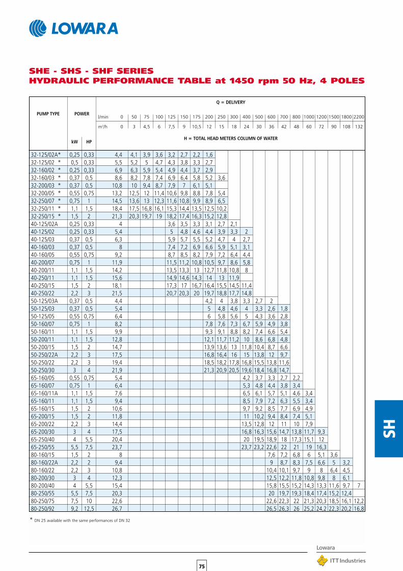
50 75 100 125 150 175 200 250 300 400 500 600 700 800 1000 1200 1500 1800 2200
3 4,5 6 7,5 9 10,5 12 15 18 24 30 36 42 48 60 72 90 108 132
75
SH
SHE - SHS - SHF SERIESHYDRAULIC PERFORMANCE TABLE at 1450 rpm 50 Hz, 4 POLES
32-125/02A* 0,25 0,33 4,4 4,1 3,9 3,6 3,2 2,7 2,2 1,632-125/02 * 0,5 0,33 5,5 5,2 5 4,7 4,3 3,8 3,3 2,732-160/02 * 0,25 0,33 6,9 6,3 5,9 5,4 4,9 4,4 3,7 2,932-160/03 * 0,37 0,5 8,6 8,2 7,8 7,4 6,9 6,4 5,8 5,2 3,632-200/03 * 0,37 0,5 10,8 10 9,4 8,7 7,9 7 6,1 5,132-200/05 * 0,55 0,75 13,2 12,5 12 11,4 10,6 9,8 8,8 7,8 5,432-250/07 * 0,75 1 14,5 13,6 13 12,3 11,6 10,8 9,9 8,9 6,532-250/11 * 1,1 1,5 18,4 17,5 16,8 16,1 15,3 14,4 13,5 12,5 10,232-250/15 * 1,5 2 21,3 20,3 19,7 19 18,2 17,4 16,3 15,2 12,840-125/02A 0,25 0,33 4 3,6 3,5 3,3 3,1 2,7 2,140-125/02 0,25 0,33 5,4 5 4,8 4,6 4,4 3,9 3,3 240-125/03 0,37 0,5 6,3 5,9 5,7 5,5 5,2 4,7 4 2,740-160/03 0,37 0,5 8 7,4 7,2 6,9 6,6 5,9 5,1 3,140-160/05 0,55 0,75 9,2 8,7 8,5 8,2 7,9 7,2 6,4 4,440-200/07 0,75 1 11,9 11,5 11,2 10,8 10,5 9,7 8,6 5,840-200/11 1,1 1,5 14,2 13,5 13,3 13 12,7 11,8 10,8 840-250/11 1,1 1,5 15,6 14,9 14,6 14,3 14 13 11,940-250/15 1,5 2 18,1 17,3 17 16,7 16,4 15,5 14,5 11,440-250/22 2,2 3 21,5 20,7 20,3 20 19,7 18,8 17,7 14,850-125/03A 0,37 0,5 4,4 4,2 4 3,8 3,3 2,7 250-125/03 0,37 0,5 5,4 5 4,8 4,6 4 3,3 2,6 1,850-125/05 0,55 0,75 6,4 6 5,8 5,6 5 4,3 3,6 2,850-160/07 0,75 1 8,2 7,8 7,6 7,3 6,7 5,9 4,9 3,850-160/11 1,1 1,5 9,9 9,3 9,1 8,8 8,2 7,4 6,6 5,450-200/11 1,1 1,5 12,8 12,1 11,7 11,2 10 8,6 6,8 4,850-200/15 1,5 2 14,7 13,9 13,6 13 11,8 10,4 8,7 6,650-250/22A 2,2 3 17,5 16,8 16,4 16 15 13,8 12 9,750-250/22 2,2 3 19,4 18,5 18,2 17,8 16,8 15,5 13,8 11,650-250/30 3 4 21,9 21,3 20,9 20,5 19,6 18,4 16,8 14,765-160/05 0,55 0,75 5,4 4,2 3,7 3,3 2,7 2,265-160/07 0,75 1 6,4 5,3 4,8 4,4 3,8 3,465-160/11A 1,1 1,5 7,6 6,5 6,1 5,7 5,1 4,6 3,465-160/11 1,1 1,5 9,4 8,5 7,9 7,2 6,3 5,5 3,465-160/15 1,5 2 10,6 9,7 9,2 8,5 7,7 6,9 4,965-200/15 1,5 2 11,8 11 10,2 9,4 8,4 7,4 5,165-200/22 2,2 3 14,4 13,5 12,8 12 11 10 7,965-200/30 3 4 17,5 16,8 16,3 15,6 14,7 13,8 11,7 9,365-250/40 4 5,5 20,4 20 19,5 18,9 18 17,3 15,1 1265-250/55 5,5 7,5 23,7 23,7 23,2 22,6 22 21 19 16,380-160/15 1,5 2 8 7,6 7,2 6,8 6 5,1 3,680-160/22A 2,2 2 9,4 9 8,7 8,3 7,5 6,6 5 3,280-160/22 2,2 3 10,8 10,4 10,1 9,7 9 8 6,4 4,580-200/30 3 4 12,3 12,5 12,2 11,8 10,8 9,8 8 6,180-200/40 4 5,5 15,4 15,8 15,5 15,2 14,3 13,3 11,6 9,7 780-250/55 5,5 7,5 20,3 20 19,7 19,3 18,4 17,4 15,2 12,480-250/75 7,5 10 22,6 22,6 22,3 22 21,3 20,3 18,5 16,1 12,280-250/92 9,2 12,5 26,7 26,5 26,3 26 25,2 24,2 22,3 20,2 16,8
PUMP TYPE POWER
kW HP
Q = DELIVERY
H = TOTAL HEAD METERS COLUMN OF WATER
l/min 0
m3/h 0
* DN 25 available with the same performances of DN 32

76
SH
SH 25 - SH 32 SERIESOPERATING CHARACTERISTICS at 2900 rpm 50 Hz, 2 POLES
Please verify with the price list the availability of model type SHE-SHS-SHF
These performances are valid for liquids with density ρ = 1.0 kg/dm3 and kinematic viscosity γ = 1 mm2/sec.

77
SH
SH 40 SERIESOPERATING CHARACTERISTICS at 2900 rpm 50 Hz, 2 POLES
Please verify with the price list the availability of model type SHE-SHS-SHF
These performances are valid for liquids with density ρ = 1.0 kg/dm3 and kinematic viscosity γ = 1 mm2/sec.
*
*
* /92 - 9,2 kW - 12,5 HP for version SHE - /110A - 11 kW - 15 HP for version SHS-SHF

78
SH
Please verify with the price list the availability of model type SHE-SHS-SHF
These performances are valid for liquids with density ρ = 1.0 kg/dm3 and kinematic viscosity γ = 1 mm2/sec.
SH 50 SERIESOPERATING CHARACTERISTICS at 2900 rpm 50 Hz, 2 POLES
*
*
* /92 - 9,2 kW - 12,5 HP for version SHE - /110A - 11 kW - 15 HP for version SHS-SHF

79
SH
Please verify with the price list the availability of model type SHE-SHS-SHF
These performances are valid for liquids with density ρ = 1.0 kg/dm3 and kinematic viscosity γ = 1 mm2/sec.
SH 65 SERIESOPERATING CHARACTERISTICS at 2900 rpm 50 Hz, 2 POLES
*
*
* /92 - 9,2 kW - 12,5 HP for version SHE - /110A - 11 kW - 15 HP for version SHS-SHF

80
SH
SH 80 SERIESOPERATING CHARACTERISTICS at 2900 rpm 50 Hz, 2 POLES
Please verify with the price list the availability of model type SHE-SHS-SHF
These performances are valid for liquids with density ρ = 1.0 kg/dm3 and kinematic viscosity γ = 1 mm2/sec.

81
SH
SH4 25 - SH4 32 SERIESOPERATING CHARACTERISTICS at 1450 rpm 50 Hz, 4 POLES
Please verify with the price list the availability of model type SHE4-SHS4-SHF4
These performances are valid for liquids with density ρ = 1.0 kg/dm3 and kinematic viscosity γ = 1 mm2/sec.

82
SH
SH4 40 SERIESOPERATING CHARACTERISTICS at 1450 rpm 50 Hz, 4 POLES
Please verify with the price list the availability of model type SHE4-SHS4-SHF4
These performances are valid for liquids with density ρ = 1.0 kg/dm3 and kinematic viscosity γ = 1 mm2/sec.

83
SH
SH4 50 SERIESOPERATING CHARACTERISTICS at 1450 rpm 50 Hz, 4 POLES
Please verify with the price list the availability of model type SHE4-SHS4-SHF4
These performances are valid for liquids with density ρ = 1.0 kg/dm3 and kinematic viscosity γ = 1 mm2/sec.

84
SH
SH4 65 SERIESOPERATING CHARACTERISTICS at 1450 rpm 50 Hz, 4 POLES
Please verify with the price list the availability of model type SHE4-SHS4-SHF4
These performances are valid for liquids with density ρ = 1.0 kg/dm3 and kinematic viscosity γ = 1 mm2/sec.
A

85
SH
SH4 80 SERIESOPERATING CHARACTERISTICS at 1450 rpm 50 Hz, 4 POLES
Please verify with the price list the availability of model type SHE4-SHS4-SHF4
These performances are valid for liquids with density ρ = 1.0 kg/dm3 and kinematic viscosity γ = 1 mm2/sec.
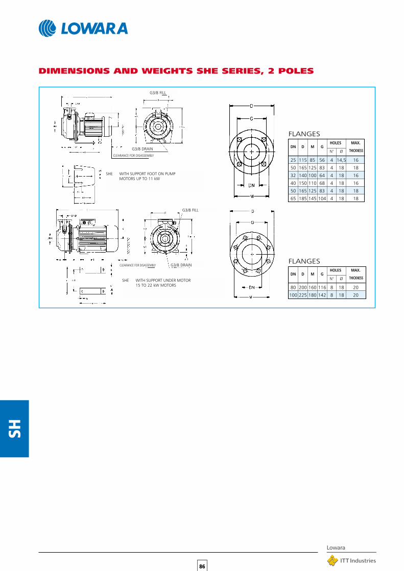
86
SH
DIMENSIONS AND WEIGHTS SHE SERIES, 2 POLES
FLANGES
SHE WITH SUPPORT FOOT ON PUMPMOTORS UP TO 11 kW
G3/8 FILL
G3/8 DRAIN
CLEARANCE FOR DISASSEMBLY
CLEARANCE FOR DISASSEMBLY
G3/8 FILL
G3/8 DRAIN
SHE WITH SUPPORT UNDER MOTOR15 TO 22 kW MOTORS
FLANGES
DN D M GHOLES MAX.
N° Ø THICKNESS
80 200 160 116 8 18 20
100 225 180 142 8 18 20
DN D M GHOLES MAX.
N° Ø THICKNESS
25 115 85 56 4 14,5 16
50 165 125 83 4 18 18
32 140 100 64 4 18 16
40 150 110 68 4 18 16
50 165 125 83 4 18 18
65 185 145 104 4 18 18

87
SH
SHE 25-125/07 25 50 80 140 – – 129 – – – 160 – – 190 – – – 218 252SHE 25-125/11 25 50 80 140 – – 129 – – – 160 – – 190 – – – 218 252SHE 25-160/15 25 50 80 160 – – 129 – – – 160 – – 210 – – – 253 320SHE 25-160/22 25 50 80 160 – – 129 – – – 160 – – 210 – – – 253 320SHE 25-200/30 25 50 80 180 – – 121 – – – 160 – – 230 – – – 285 340SHE 25-200/40 25 50 80 180 – – 133 – – – 160 – – 230 – – – 285 340SHE 25-250/55 25 50 100 225 – – 150 – – – 180 – – 265 – – – 345 405SHE 25-250/75 25 50 100 225 – – 150 – – – 180 – – 265 – – – 245 405SHE 25-250/110 25 50 100 225 – 278 191 – – – 180 – – 265 – – – 245 405SHE 32-125/07 32 50 80 140 – – 129 – – – 112 – – 190 – – – 218 252SHE 32-125/11 32 50 80 140 – – 129 – – – 112 – – 190 – – – 218 252SHE 32-160/15 32 50 80 160 – – 129 – – – 132 – – 210 – – – 253 292SHE 32-160/22 32 50 80 160 – – 129 – – – 132 – – 210 – – – 253 292SHE 32-200/30 32 50 80 180 – – 121 – – – 160 – – 230 – – – 285 340SHE 32-200/40 32 50 80 180 – – 133 – – – 160 – – 230 – – – 285 340SHE 32-250/55 32 50 100 225 – – 150 – – – 180 – – 265 – – – 345 405SHE 32-250/75 32 50 100 225 – – 150 – – – 180 – – 265 – – – 345 405SHE 32-250/110 32 50 100 225 – 278 191 – – – 180 – – 265 – – – 345 405SHE 40-125/11 40 65 80 140 – – 129 – – – 112 – – 190 – – – 219 252SHE 40-125/15 40 65 80 140 – – 129 – – – 112 – – 190 – – – 219 252SHE 40-125/22 40 65 80 140 – – 129 – – – 112 – – 190 – – – 219 252SHE 40-160/30 40 65 80 160 – – 121 – – – 132 – – 210 – – – 254 292SHE 40-160/40 40 65 80 160 – – 133 – – – 132 – – 210 – – – 254 292SHE 40-200/55 40 65 100 180 – – 150 – – – 160 – – 230 – – – 285 340SHE 40-200/75 40 65 100 180 – – 150 – – – 160 – – 230 – – – 285 340SHE 40-250/92 40 65 100 225 – 278 191 – – – 180 – – 265 – – – 345 405SHE 40-250/110 40 65 100 225 – 278 191 – – – 180 – – 265 – – – 345 405SHE 40-250/150 40 65 100 225 208 – 232 72 22 20 180 260 210 318 254 13 23 345 412SHE 50-125/22 50 65 100 160 – – 129 – – – 132 – – 210 – – – 254 292SHE 50-125/30 50 65 100 160 – – 121 – – – 132 – – 210 – – – 254 292SHE 50-125/40 50 65 100 160 – – 135 – – – 132 – – 210 – – – 254 292SHE 50-160/55 50 65 100 180 – – 150 – – – 160 – – 210 – – – 255 340SHE 50-160/75 50 65 100 180 – – 150 – – – 160 – – 210 – – – 255 340SHE 50-200/92 50 65 100 200 – 278 191 – – – 160 – – 245 – – – 310 360SHE 50-200/110 50 65 100 200 – 278 191 – – – 160 – – 245 – – – 310 360SHE 50-250/150 50 65 100 225 208 – 232 72 22 20 180 260 210 318 254 13 23 345 412SHE 50-250/185 50 65 100 225 208 – 232 72 22 20 180 304 254 318 254 13 23 345 412SHE 50-250/220 50 65 100 225 208 – 232 72 22 20 180 304 254 318 254 13 23 345 412SHE 65-160/40 65 80 100 200 – – 133 – – – 160 – – 245 – – – 310 360SHE 65-160/55 65 80 100 200 – – 150 – – – 160 – – 245 – – – 310 360SHE 65-160/75 65 80 100 200 – – 150 – – – 160 – – 245 – – – 310 360SHE 65-160/92 65 80 100 200 – 278 191 – – – 160 – – 245 – – – 310 360SHE 65-160/110 65 80 100 200 – 278 191 – – – 160 – – 245 – – – 310 360SHE 65-200/150 65 80 100 225 208 – 232 72 22 20 180 260 210 318 254 13 23 310 412SHE 65-200/185 65 80 100 225 208 – 232 72 22 20 180 304 254 318 254 13 23 310 412SHE 65-200/220 65 80 100 225 208 – 232 72 22 20 180 304 254 318 254 13 23 310 412SHE 80-160/110 80 100 125 235 – 278 191 – – – 180 – – 265 – – – 345 405SHE 80-160/150 80 100 125 235 208 – 232 72 22 20 180 260 210 318 254 13 23 345 412SHE 80-160/185 80 100 125 235 208 – 232 72 22 20 180 304 254 318 254 13 23 345 412SHE 80-200/220 80 100 125 250 208 – 232 72 22 20 180 304 254 318 254 13 23 345 430
443 98 20443 98 22443 98 23443 98 25461 98 29487 98 36553 98 48553 98 60604 98 80443 96 20443 96 22443 96 23443 96 25461 96 29487 96 36553 96 48553 96 60604 96 80443 100 23443 100 25443 100 26461 100 29487 100 35553 100 46553 100 51604 107 62604 107 65688 107 91463 104 29481 104 32507 104 35553 104 47553 104 52604 104 63604 104 67688 107 103732 107 119732 107 136507 115 60553 115 69553 115 75604 130 92604 130 101688 130 116732 130 126732 130 139629 160 102713 160 120757 160 139757 160 150
DIMENSIONS AND WEIGHTS SHE SERIES, 2 POLES
PUMP PUMP SUPPORT B H L k WEIGHTTYPE max kgDNM DNA a h2 w w1 x b c c1 h1 m m1 n n1 s s1

88
SH
DIMENSIONS AND WEIGHTS SHE4 SERIES, 4 POLES
HOLES MAX.DN D M G
N° DIA. THICKNESS
32 140 100 64 4 18 16
40 150 110 68 4 18 16
50 165 125 83 4 18 18
65 185 145 104 4 18 18
FLANGES
G 3/8 FILL
G 3/8 DRAIN
CLEARANCE FOR DISASSEMBLY
FLANGES
DN D M GHOLES MAX.
N° Ø THICKNESS
80 200 160 116 8 18 20
100 225 180 142 8 18 20

SHE4 25-125/02A 25 50 80 140 – 121 160 190 130 218 252 411 98 20SHE4 25-125/02 25 50 80 140 – 121 160 190 130 218 252 411 98 20SHE4 25-160/02 25 50 80 160 – 121 160 210 130 253 320 411 98 22SHE4 25-160/03 25 50 80 160 – 121 160 210 130 253 320 411 98 23SHE4 25-200/03 25 50 80 180 – 121 160 230 130 285 340 411 98 28SHE4 25-200/05 25 50 80 180 – 129 160 230 130 285 340 443 98 30SHE4 25-250/07 25 50 100 225 – 129 180 265 130 345 405 463 98 38SHE4 25-250/11 25 50 100 225 – 121 180 265 130 345 405 481 98 40SHE4 25-250/15 25 50 100 225 – 121 180 265 130 345 405 481 98 45SHE4 32-125/02A 32 50 80 140 – 121 112 190 130 218 252 411 98 20SHE4 32-125/02 32 50 80 140 – 121 112 190 130 218 252 411 98 20SHE4 32-160/02 32 50 80 160 – 121 132 210 130 253 292 411 98 22SHE4 32-160/03 32 50 80 160 – 121 132 210 130 253 292 411 98 23SHE4 32-200/03 32 50 80 180 – 121 160 230 130 285 340 411 98 28SHE4 32-200/05 32 50 80 180 – 129 160 230 130 285 340 443 98 30SHE4 32-250/07 32 50 100 225 – 129 180 265 130 345 405 463 98 38SHE4 32-250/11 32 50 100 225 – 121 180 265 130 345 405 481 98 40SHE4 32-250/15 32 50 100 225 – 121 180 265 130 345 405 481 98 45SHE4 40-125/02A 40 65 80 140 – 121 112 190 130 219 252 411 100 21SHE4 40-125/02 40 65 80 140 – 121 112 190 130 219 252 411 100 21SHE4 40-125/03 40 65 80 140 – 121 112 190 130 219 252 411 100 22SHE4 40-160/03 40 65 80 160 – 121 132 210 130 254 292 411 100 24SHE4 40-160/05 40 65 80 160 – 129 132 210 130 254 292 411 100 25SHE4 40-200/07 40 65 100 180 – 129 160 230 130 285 340 443 100 26SHE4 40-200/11 40 65 100 180 – 121 160 230 130 285 340 463 100 30SHE4 40-250/11 40 65 100 225 – 121 180 265 130 345 405 481 107 32SHE4 40-250/15 40 65 100 225 – 121 180 265 130 345 405 481 107 42SHE4 40-250/22 40 65 100 225 – 133 180 265 130 345 405 507 107 49SHE4 50-125/03A 50 65 100 160 – 121 132 210 130 254 292 431 104 22SHE4 50-125/03 50 65 100 160 – 121 132 210 130 254 292 431 104 22SHE4 50-125/05 50 65 100 160 – 129 132 210 130 254 292 463 104 24SHE4 50-160/07 50 65 100 180 – 129 160 210 130 255 340 463 104 26SHE4 50-160/11 50 65 100 180 – 121 160 210 130 255 340 481 104 28SHE4 50-200/11 50 65 100 200 – 121 160 245 130 310 360 481 104 30SHE4 50-200/15 50 65 100 200 – 121 160 245 130 310 360 481 104 41SHE4 50-250/22A 50 65 100 225 – 133 180 265 130 345 405 507 107 46SHE4 50-250/22 50 65 100 225 – 133 180 265 130 345 405 507 107 46SHE4 50-250/30 50 65 100 225 – 133 180 265 130 345 405 507 107 55SHE4 65-160/05 65 80 100 200 – 129 160 245 130 310 360 463 115 32SHE4 65-160/07 65 80 100 200 – 129 160 245 130 310 360 463 115 35SHE4 65-160/11A 65 80 100 200 – 121 160 245 130 310 360 481 115 38SHE4 65-160/11 65 80 100 200 – 121 160 245 130 310 360 481 130 38SHE4 65-160/15 65 80 100 200 – 121 160 245 130 310 360 481 130 42SHE4 65-200/15 65 80 100 225 – 121 180 245 130 310 405 481 130 45SHE4 65-200/22 65 80 100 225 – 133 180 245 130 310 405 507 130 50SHE4 65-200/30 65 80 100 225 – 133 180 245 130 310 405 507 130 55SHE4 65-250/40 65 80 100 250 – 150 200 265 130 345 450 530 140 64SHE4 65-250/55 65 80 100 250 – 191 200 265 130 345 450 566 140 78SHE4 80-160/15 80 100 125 225 – 121 180 265 130 345 405 506 160 49SHE4 80-160/22A 80 100 125 225 – 133 180 265 130 345 405 532 160 54SHE4 80-160/22 80 100 125 225 – 133 180 265 130 345 405 532 160 54SHE4 80-200/30 80 100 125 250 – 133 180 265 130 345 430 532 160 59SHE4 80-200/40 80 100 125 250 – 150 180 265 130 345 430 555 160 65SHE4 80-250/55 80 100 125 280 259 191 200 303 210 384 480 591 160 79SHE4 80-250/75 80 100 125 280 278 191 200 303 210 384 480 629 160 87SHE4 80-250/92 80 100 125 280 278 191 200 303 210 384 480 629 160 88
89
SH
PUMP PUMP DIMENSIONS IN mm B H L k WEIGHTTYPE
DNM DNA a h2 w1 x h1 n n1 max kg
DIMENSIONS AND WEIGHTS SHE4 SERIES, 4 POLES

90
SH
SHS WITH SUPPORT FOOT ON PUMPMOTORS UP TO 7,5 kW
G3/8 FILL
G3/8 FILL
G3/8 DRAIN
DIMENSIONS AND WEIGHTS SHS SERIES, 2 POLES
FLANGES
DN D M GHOLES MAX.
N° Ø THICKNESS
25 115 85 56 4 14,5 16
50 165 125 83 4 18 18
32 140 100 64 4 18 16
40 150 110 68 4 18 16
50 165 125 83 4 18 18
65 185 145 104 4 18 18
FLANGES
DN D M GHOLES MAX.
N° Ø THICKNESS
80 200 160 116 8 18 20
100 225 180 142 8 18 20
G3/8 DRAIN
SHS WITH SUPPORT UNDER MOTOR11 TO 37 kW MOTORS
CLEARANCE FOR DISASSEMBLY
CLEARANCE FOR DISASSEMBLY

91
SH
218 252 461 98 25218 252 498 98 26253 320 498 98 28253 320 498 98 30285 340 548 98 41285 340 552 98 44345 405 666 98 63345 405 666 98 69350 412 810 98 81218 252 461 98 25218 252 498 98 26253 292 498 98 28253 292 498 98 30285 340 548 98 41285 340 552 98 44345 405 666 98 63345 405 666 98 69350 412 810 98 81219 252 498 100 25219 252 498 100 27219 252 498 100 28254 292 548 100 38254 292 552 100 42300 340 666 100 64300 340 666 100 66350 412 810 107 116350 412 810 107 116350 412 810 107 122254 292 518 104 34254 292 568 104 37254 292 572 104 42255 340 666 104 60255 340 666 104 65350 412 810 104 90350 412 810 104 90350 412 810 107 115350 412 854 107 125350 412 854 107 145310 360 572 115 67310 360 666 115 75310 360 666 115 80350 412 810 130 106350 412 810 130 106350 412 810 130 122350 412 854 130 135350 412 854 130 149400 457 941 140 189400 457 941 140 200350 412 835 155 111350 412 835 155 127350 412 879 155 148350 430 879 155 157400 457 966 155 191400 457 966 155 203
DIMENSIONS AND WEIGHTS SHS SERIES, 2 POLES
PUMP PUMP SUPPORT B H L k WEIGHTTYPE
max kgDNM DNA a f h2 w w1 x b c c1 h1 m m1 n n1 s s1
SHS 25-125/07 25 50 80 155 140 – – 121 – – – 160 – – 190 – – –SHS 25-125/11 25 50 80 155 140 – – 129 – – – 160 – – 190 – – –SHS 25-160/15 25 50 80 155 160 – – 129 – – – 160 – – 210 – – –SHS 25-160/22 25 50 80 155 160 – – 129 – – – 160 – – 210 – – –SHS 25-200/30 25 50 80 165 180 – – 121 – – – 160 – – 230 – – –SHS 25-200/40 25 50 80 165 180 – – 133 – – – 160 – – 230 – – –SHS 25-250/55 25 50 100 192 225 – 424 150 – – – 180 – – 265 – – –SHS 25-250/75 25 50 100 192 225 – 424 150 – – – 180 – – 265 – – –SHS 25-250/110 25 50 100 222 225 330 – 232 72 22 20 180 260 210 318 254 14 23SHS 32-125/07 32 50 80 155 140 – – 121 – – – 112 – – 190 – – –SHS 32-125/11 32 50 80 155 140 – – 129 – – – 112 – – 190 – – –SHS 32-160/15 32 50 80 155 160 – – 129 – – – 132 – – 210 – – –SHS 32-160/22 32 50 80 155 160 – – 129 – – – 132 – – 210 – – –SHS 32-200/30 32 50 80 165 180 – – 121 – – – 160 – – 230 – – –SHS 32-200/40 32 50 80 165 180 – – 133 – – – 160 – – 230 – – –SHS 32-250/55 32 50 100 192 225 – 424 150 – – – 180 – – 265 – – –SHS 32-250/75 32 50 100 192 225 – 424 150 – – – 180 – – 265 – – –SHS 32-250/110 32 50 100 222 225 330 – 232 72 22 20 180 260 210 318 254 14 23SHS 40-125/11 40 65 80 155 140 – – 129 – – – 112 – – 190 – – –SHS 40-125/15 40 65 80 155 140 – – 129 – – – 112 – – 190 – – –SHS 40-125/22 40 65 80 155 140 – – 129 – – – 112 – – 190 – – –SHS 40-160/30 40 65 80 165 160 – – 121 – – – 132 – – 210 – – –SHS 40-160/40 40 65 80 165 160 – – 133 – – – 132 – – 210 – – –SHS 40-200/55 40 65 100 192 180 – 424 150 – – – 160 – – 230 – – –SHS 40-200/75 40 65 100 192 180 – 424 150 – – – 160 – – 230 – – –SHS 40-250/110A 40 65 100 222 225 330 – 232 72 22 20 180 260 210 318 254 14 23SHS 40-250/110 40 65 100 222 225 330 – 232 72 22 20 180 260 210 318 254 14 23SHS 40-250/150 40 65 100 222 225 330 – 232 72 22 20 180 260 210 318 254 14 23SHS 50-125/22 50 65 100 155 160 – – 129 – – – 132 – – 210 – – –SHS 50-125/30 50 65 100 165 160 – – 121 – – – 132 – – 210 – – –SHS 50-125/40 50 65 100 165 160 – – 133 – – – 132 – – 210 – – –SHS 50-160/55 50 65 100 192 180 – 424 150 – – – 160 – – 210 – – –SHS 50-160/75 50 65 100 192 180 – 424 150 – – – 160 – – 210 – – –SHS 50-200/110A 50 65 100 222 200 330 – 232 72 22 20 180 260 210 318 254 14 23SHS 50-200/110 50 65 100 222 200 330 – 232 72 22 20 180 260 210 318 254 14 23SHS 50-250/150 50 65 100 222 225 330 – 232 72 22 20 180 260 210 318 254 14 23SHS 50-250/185 50 65 100 222 225 330 – 232 72 22 20 180 304 254 318 254 14 23SHS 50-250/220 50 65 100 222 225 330 – 232 72 22 20 180 304 254 318 254 14 23SHS 65-160/40 65 80 100 165 200 – – 133 – – – 160 – – 245 – – –SHS 65-160/55 65 80 100 192 200 – 424 150 – – – 160 – – 245 – – –SHS 65-160/75 65 80 100 192 200 – 424 150 – – – 160 – – 245 – – –SHS 65-160/110A 65 80 100 222 200 330 – 232 72 22 20 180 260 210 318 254 14 23SHS 65-160/110 65 80 100 222 200 330 – 232 72 22 20 180 260 210 318 254 14 23SHS 65-200/150 65 80 100 222 225 330 – 232 72 22 20 180 260 210 318 254 14 23SHS 65-200/185 65 80 100 222 225 330 – 232 72 22 20 180 304 254 318 254 14 23SHS 65-200/220 65 80 100 222 225 330 – 232 72 22 20 180 304 254 318 254 14 23SHS 65-250/300 65 80 100 228 250 361 – 257 60 24 – 200 345 305 360 318 18 18SHS 65-250/370 65 80 100 228 250 361 – 257 60 24 – 200 345 305 360 318 18 18SHS 80-160/110 80 100 125 222 225 330 – 232 72 22 20 180 260 210 318 254 14 23SHS 80-160/150 80 100 125 222 225 330 – 232 72 22 20 180 260 210 318 254 14 23SHS 80-160/185 80 100 125 222 225 330 – 232 72 22 20 180 304 254 318 254 14 23SHS 80-200/220 80 100 125 222 250 330 – 232 72 22 20 180 304 254 318 254 14 23SHS 80-200/300 80 100 125 228 250 361 – 257 60 24 – 200 345 305 360 318 18 18SHS 80-200/370 80 100 125 228 250 361 – 257 60 24 – 200 345 305 360 318 18 18
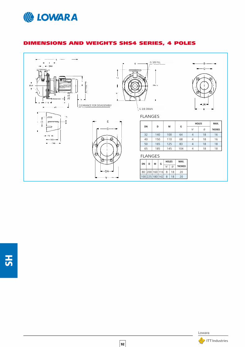
92
SH
DIMENSIONS AND WEIGHTS SHS4 SERIES, 4 POLES
HOLES MAX.DN D M G
N° Ø THICKNESS
32 140 100 64 4 18 16
40 150 110 68 4 18 16
50 165 125 83 4 18 18
65 185 145 104 4 18 18
FLANGES
G 3/8 FILL
G 3/8 DRAINCLEARANCE FOR DISASSEMBLY
FLANGES
DN D M GHOLES MAX.
N° Ø THICKNESS
80 200 160 116 8 18 20
100 225 180 142 8 18 20

93
SH
SHS4 25-250/07 25 50 100 155 225 – 129 180 265 – 345 405 518 98 41SHS4 25-250/11 25 50 100 155 225 – 121 180 265 – 345 405 536 98 43SHS4 25-250/15 25 50 100 155 225 – 121 180 265 – 345 405 536 98 47SHS4 32-250/07 32 50 100 155 225 – 129 180 265 130 345 405 518 98 41SHS4 32-250/11 32 50 100 155 225 – 121 180 265 130 345 405 536 98 43SHS4 32-250/15 32 50 100 155 225 – 121 180 265 130 345 405 536 98 47SHS4 40-200/07 40 65 100 155 180 – 129 160 230 130 285 340 518 100 28SHS4 40-200/11 40 65 100 155 180 – 121 160 230 130 285 340 536 100 32SHS4 40-250/11 40 65 100 155 225 – 121 180 265 130 345 405 536 107 33SHS4 40-250/15 40 65 100 155 225 – 121 180 265 130 345 405 536 107 46SHS4 40-250/22 40 65 100 165 225 – 133 180 265 130 345 405 572 107 52SHS4 50-160/07 50 65 100 155 180 – 129 160 210 130 255 340 518 104 27SHS4 50-160/11 50 65 100 155 180 – 121 160 210 130 255 340 536 104 30SHS4 50-200/11 50 65 100 155 200 – 121 160 245 130 310 360 536 104 34SHS4 50-200/15 50 65 100 155 200 – 121 160 245 130 310 360 536 104 42SHS4 50-250/22A 50 65 100 165 225 – 133 180 265 130 345 405 572 107 49SHS4 50-250/22 50 65 100 165 225 – 133 180 265 130 345 405 572 107 49SHS4 50-250/30 50 65 100 165 225 – 133 180 265 130 345 405 572 107 58SHS4 65-160/05 65 80 100 155 200 – 129 160 245 130 310 360 518 115 34SHS4 65-160/07 65 80 100 155 200 – 129 160 245 130 310 360 518 115 37SHS4 65-160/11A 65 80 100 155 200 – 121 160 245 130 310 360 536 115 40SHS4 65-160/11 65 80 100 155 200 – 121 160 245 130 310 360 536 130 40SHS4 65-160/15 65 80 100 155 200 – 121 160 245 130 310 360 536 130 45SHS4 65-200/15 65 80 100 155 225 – 121 180 245 130 310 405 536 130 48SHS4 65-200/22 65 80 100 165 225 – 133 180 245 130 310 405 572 130 54SHS4 65-200/30 65 80 100 165 225 – 133 180 245 130 310 405 572 130 59SHS4 65-250/40 65 80 100 165 250 – 150 200 265 130 345 450 595 140 65SHS4 65-250/55 65 80 100 192 250 351 191 200 265 130 345 450 658 140 79SHS4 80-160/15 80 100 125 155 225 – 121 180 265 130 345 405 561 160 53SHS4 80-160/22A 80 100 125 165 225 – 133 180 265 130 345 405 597 160 58SHS4 80-160/22 80 100 125 165 225 – 133 180 265 130 345 405 597 160 58SHS4 80-200/30 80 100 125 165 250 – 133 180 265 130 345 430 597 160 63SHS4 80-200/40 80 100 125 165 250 – 150 180 265 130 345 430 620 160 68SHS4 80-250/55 80 100 125 192 280 351 191 200 303 210 384 480 683 160 85SHS4 80-250/75 80 100 125 192 280 370 191 200 303 210 384 480 721 160 90SHS4 80-250/92 80 100 125 192 280 370 191 200 303 210 384 480 721 160 91
PUMP PUMP DIMENSIONS IN mm WEIGHTTYPE
B H L k
DNM DNA a f h2 w1 x h1 n n1 max kg
DIMENSIONS AND WEIGHTS SHS4 SERIES, 4 POLES

94
SH
DIMENSIONS AND WEIGHTS SHF SERIES, 2 POLES
G 3/8 FILL
G 3/8 DRAIN
FLANGES
DN D M GHOLES MAX.
N° Ø THICKNESS
80 200 160 116 8 18 20
100 225 180 142 8 18 20
FLANGES
DN D M GHOLES MAX.
N° Ø THICKNESS
32 140 100 64 4 18 16
40 150 110 68 4 18 16
50 165 125 83 4 18 18
65 185 145 104 4 18 18

SHF 25-125/07 25 50 80 320 360 744 540 800 130 60 212 140 352 M16 65SHF 25-125/11 25 50 80 320 360 744 540 800 130 60 212 140 352 M16 67SHF 25-160/15 25 50 80 350 390 773 600 900 150 60 232 160 392 M16 69SHF 25-160/22 25 50 80 350 390 773 600 900 150 60 232 160 392 M16 71SHF 25-200/30 25 50 80 350 390 809 600 900 150 60 260 180 440 M16 90SHF 25-200/40 25 50 80 350 390 832 600 900 150 60 260 180 440 M16 94SHF 25-250/55 25 50 100 440 490 909 740 1120 190 75 280 225 505 M20 126SHF 25-250/75 25 50 100 440 490 909 740 1120 190 75 280 225 505 M20 131SHF 25-250/110 25 50 100 490 540 1061 840 1250 205 75 280 225 512 M20 176SHF 32-125/07 32 50 80 320 360 744 540 800 130 60 212 140 352 M16 65SHF 32-125/11 32 50 80 320 360 744 540 800 130 60 212 140 352 M16 67SHF 32-160/15 32 50 80 350 390 773 600 900 150 60 232 160 392 M16 69SHF 32-160/22 32 50 80 350 390 773 600 900 150 60 232 160 392 M16 71SHF 32-200/30 32 50 80 350 390 809 600 900 150 60 260 180 440 M16 90SHF 32-200/40 32 50 80 350 390 832 600 900 150 60 260 180 440 M16 94SHF 32-250/55 32 50 100 440 490 909 740 1120 190 75 280 225 505 M20 126SHF 32-250/75 32 50 100 440 490 909 740 1120 190 75 280 225 505 M20 131SHF 32-250/110 32 50 100 490 540 1061 840 1250 205 75 280 225 512 M20 176SHF 40-125/11 40 65 80 320 360 744 540 800 130 60 212 140 352 M16 68SHF 40-125/15 40 65 80 350 390 773 600 900 150 60 212 140 352 M16 70SHF 40-125/22 40 65 80 350 390 773 600 900 150 60 212 140 352 M16 73SHF 40-160/30 40 65 80 350 390 809 600 900 150 60 232 160 392 M16 87SHF 40-160/40 40 65 80 350 390 832 600 900 150 60 232 160 392 M16 93SHF 40-200/55 40 65 100 400 450 909 660 1000 170 60 260 180 451 M20 108SHF 40-200/75 40 65 100 400 450 909 660 1000 170 60 260 180 451 M20 116SHF 40-250/110A 40 65 100 490 540 1061 840 1250 205 75 280 225 512 M20 174SHF 40-250/110 40 65 100 490 540 1061 840 1250 205 75 280 225 512 M20 174SHF 40-250/150 40 65 100 490 540 1061 840 1250 205 75 280 225 512 M20 184SHF 50-125/22 50 65 100 350 390 793 600 900 150 60 232 160 392 M16 80SHF 50-125/30 50 65 100 350 390 829 600 900 150 60 232 160 392 M16 87SHF 50-125/40 50 65 100 350 390 852 600 900 150 60 232 160 392 M16 92SHF 50-160/55 50 65 100 400 450 909 660 1000 170 60 260 180 451 M20 106SHF 50-160/75 50 65 100 400 450 909 660 1000 170 60 260 180 451 M20 110SHF 50-200/110A 50 65 100 440 490 1061 740 1120 190 60 260 200 492 M20 168SHF 50-200/110 50 65 100 440 490 1061 740 1120 190 60 260 200 492 M20 168SHF 50-250/150 50 65 100 490 540 1061 840 1250 205 75 280 225 512 M20 174SHF 50-250/185 50 65 100 490 540 1105 840 1250 205 75 280 225 512 M20 194SHF 50-250/220 50 65 100 490 540 1111 840 1250 205 75 280 225 510 M20 214SHF 65-160/40 65 80 100 400 450 852 660 1000 170 75 260 200 460 M20 130SHF 65-160/55 65 80 100 440 490 909 740 1120 190 75 260 200 460 M20 136SHF 65-160/75 65 80 100 440 490 909 740 1120 190 75 260 200 460 M20 142SHF 65-160/110A 65 80 100 490 540 1061 840 1250 205 75 260 200 492 M20 157SHF 65-160/110 65 80 100 490 540 1061 840 1250 205 75 260 200 492 M20 157SHF 65-200/150 65 80 100 490 540 1061 840 1250 205 75 280 225 512 M20 180SHF 65-200/185 65 80 100 490 540 1105 840 1250 205 75 280 225 512 M20 192SHF 65-200/220 65 80 100 490 540 1111 840 1250 205 75 280 225 510 M20 208SHF 65-250/300 65 80 100 550 610 1296 940 1400 230 90 310 250 557 M24 271SHF 65-250/370 65 80 100 550 610 1296 940 1400 230 90 310 250 557 M24 296SHF 80-160/110 80 100 125 490 540 1086 840 1250 205 75 280 225 512 M20 193SHF 80-160/150 80 100 125 490 540 1086 840 1250 205 75 280 225 512 M20 204SHF 80-160/185 80 100 125 490 540 1130 840 1250 205 75 280 225 512 M20 225SHF 80-200/220 80 100 125 490 540 1246 840 1250 205 75 280 250 530 M20 236SHF 80-200/300 80 100 125 550 610 1321 940 1400 230 75 310 250 557 M24 277SHF 80-200/370 80 100 125 550 610 1321 940 1400 230 75 310 250 557 M24 295SHF 80-250/450 80 100 125 550 610 1398 940 1400 230 90 365 280 605 M24 355SHF 80-250/550 80 100 125 600 660 1428 1060 1600 270 90 390 280 660 M24 394SHF 80-250/750 80 100 125 670 730 1558 1200 1800 300 90 420 280 735 M24 510
95
SH
PUMPDIMENSIONS (mm)
WEIGHTTYPE
DNM DNA a B1 B2 L1 L2 L3 G M h1 h2 Hmaxs
kgfor screws
DIMENSIONS AND WEIGHTS SHF SERIES, 2 POLES

96
SH
G 3/8 FILL
G 3/8 DRAIN
DIMENSIONS AND WEIGHTS SHF4 SERIES, 4 POLES
FLANGES
DN D M GHOLES MAX.
N° Ø THICKNESS
80 200 160 116 8 18 20
100 225 180 142 8 18 20
FLANGES
DN D M GHOLES MAX.
N° Ø THICKNESS
32 140 100 64 4 18 16
40 150 110 68 4 18 16
50 165 125 83 4 18 18
65 185 145 104 4 18 18

SHF4 25-125/02A 25 50 80 320 360 702 540 800 130 60 212 140 352 M16 72SHF4 25-125/02 25 50 80 320 360 702 540 800 130 60 212 140 352 M16 72SHF4 25-160/02 25 50 80 320 360 702 540 800 130 60 232 160 392 M16 74SHF4 25-160/03 25 50 80 320 360 702 540 800 130 60 232 160 392 M16 76SHF4 25-200/03 25 50 80 320 360 702 540 800 130 60 260 180 440 M16 78SHF4 25-200/05 25 50 80 320 360 744 540 800 130 60 260 180 440 M16 80SHF4 25-250/07 25 50 100 400 450 764 660 1000 170 75 280 225 505 M20 97SHF4 25-250/11 25 50 100 400 450 793 660 1000 170 75 280 225 505 M20 100SHF4 25-250/15 25 50 100 400 450 793 660 1000 170 75 280 225 505 M20 102SHF4 32-125/02A 32 50 80 320 360 702 540 800 130 60 212 140 352 M16 72SHF4 32-125/02 32 50 80 320 360 702 540 800 130 60 212 140 352 M16 72SHF4 32-160/02 32 50 80 320 360 702 540 800 130 60 232 160 392 M16 74SHF4 32-160/03 32 50 80 320 360 702 540 800 130 60 232 160 392 M16 76SHF4 32-200/03 32 50 80 320 360 702 540 800 130 60 260 180 440 M16 78SHF4 32-200/05 32 50 80 320 360 744 540 800 130 60 260 180 440 M16 80SHF4 32-250/07 32 50 100 400 450 764 660 1000 170 75 280 225 505 M20 97SHF4 32-250/11 32 50 100 400 450 793 660 1000 170 75 280 225 505 M20 100SHF4 32-250/15 32 50 100 400 450 793 660 1000 170 75 280 225 505 M20 102SHF4 40-125/02A 40 65 80 320 360 702 540 800 130 60 212 140 352 M16 57SHF4 40-125/02 40 65 80 320 360 702 540 800 130 60 212 140 352 M16 57SHF4 40-125/03 40 65 80 320 360 702 540 800 130 60 212 140 352 M16 58SHF4 40-160/03 40 65 80 320 360 702 540 800 130 60 232 160 392 M16 60SHF4 40-160/05 40 65 80 320 360 744 540 800 130 60 232 160 392 M16 62SHF4 40-200/07 40 65 100 350 390 764 600 900 150 60 260 180 440 M16 69SHF4 40-200/11 40 65 100 350 390 793 600 900 150 60 260 180 440 M16 72SHF4 40-250/11 40 65 100 400 450 793 660 1000 170 75 280 225 505 M20 99SHF4 40-250/15 40 65 100 400 450 793 660 1000 170 75 280 225 505 M20 102SHF4 40-250/22 40 65 100 400 450 829 660 1000 170 75 280 225 505 M20 115SHF4 50-125/03A 50 65 100 320 360 722 540 800 130 60 232 160 392 M16 59SHF4 50-125/03 50 65 100 320 360 722 540 800 130 60 232 160 392 M16 59SHF4 50-125/05 50 65 100 320 360 764 540 800 130 60 260 180 440 M16 61SHF4 50-160/07 50 65 100 350 390 764 600 900 150 60 260 180 440 M16 68SHF4 50-160/11 50 65 100 350 390 793 600 900 150 60 260 200 460 M16 71SHF4 50-200/11 50 65 100 350 390 793 600 900 150 60 260 200 460 M16 82SHF4 50-200/15 50 65 100 350 390 793 600 900 150 60 260 200 460 M16 85SHF4 50-250/22A 50 65 100 400 450 829 660 1000 170 75 280 225 505 M20 116SHF4 50-250/22 50 65 100 400 450 829 660 1000 170 75 280 225 505 M20 116SHF4 50-250/30 50 65 100 400 450 829 660 1000 170 75 280 225 505 M20 120SHF4 65-160/05 65 80 100 350 390 764 600 900 150 75 260 200 460 M16 84SHF4 65-160/07 65 80 100 350 390 764 600 900 150 75 260 200 460 M16 85SHF4 65-160/11A 65 80 100 400 450 793 660 1000 170 75 260 200 460 M20 88SHF4 65-160/11 65 80 100 400 450 793 660 1000 170 75 260 200 460 M20 88SHF4 65-160/15 65 80 100 400 450 793 660 1000 170 75 260 200 460 M20 91SHF4 65-200/15 65 80 100 400 450 793 660 1000 170 75 280 225 505 M20 103SHF4 65-200/22 65 80 100 440 490 829 740 1120 190 75 280 225 505 M20 117SHF4 65-200/30 65 80 100 440 490 829 740 1120 190 75 280 225 505 M20 121SHF4 65-250/40 65 80 100 440 490 962 740 1120 190 90 310 250 550 M20 158SHF4 65-250/55 65 80 100 440 490 1019 740 1120 190 90 310 250 550 M20 174SHF4 80-160/15 80 100 125 400 450 818 660 1000 170 75 280 225 505 M20 121SHF4 80-160/22A 80 100 125 440 490 854 740 1120 190 75 280 225 505 M20 127SHF4 80-160/22 80 100 125 440 490 854 740 1120 190 75 280 225 505 M20 127SHF4 80-200/30 80 100 125 440 490 964 740 1120 190 75 280 250 530 M20 146SHF4 80-200/40 80 100 125 440 490 987 740 1120 190 75 280 250 530 M20 151SHF4 80-250/55 80 100 125 490 540 1044 840 1250 205 90 310 280 580 M20 175SHF4 80-250/75 80 100 125 490 540 1082 840 1250 205 90 310 280 580 M20 185SHF4 80-250/92 80 100 125 490 540 1082 840 1250 205 90 310 280 580 M20 185
97
SH
DIMENSIONS AND WEIGHTS SHF4 SERIES, 4 POLES
PUMPDIMENSIONS (mm)
WEIGHTTYPE
DNM DNA a B1 B2 L1 L2 L3 G M h1 h2 Hmaxs
kgfor screws

PUMP TYPE DIMENSIONS (mm) B k WEIGHT
DNM DNA a d f h1 h2 kg
SHF 32-125 32 50 80 24 360 112 140 218 98 16SHF 32-160 32 50 80 24 360 132 160 253 98 18SHF 32-200 32 50 80 24 360 160 180 285 98 20SHF 32-250 32 50 100 24 360 180 225 345 98 36SHF 40-125 40 65 80 24 360 112 140 219 100 17SHF 40-160 40 65 80 24 360 132 160 254 100 18SHF 40-200 40 65 100 24 360 160 180 285 100 20SHF 40-250 40 65 100 24 360 180 225 345 100 36SHF 50-125 50 65 100 24 360 132 160 254 100 18SHF 50-160 50 65 100 24 360 160 180 255 100 19SHF 50-200 50 65 100 24 360 160 200 310 100 30SHF 50-250 50 65 100 24 360 180 225 345 100 36SHF 65-160 65 80 100 24 360 160 200 310 100 21SHF 65-200 65 80 100 24 360 180 225 310 100 31SHF 65-250 65 80 100 32 470 200 250 345 130 42SHF 80-160 80 100 125 24 360 180 225 345 140 22SHF 80-200 80 100 125 32 470 180 250 345 140 37SHF 80-250 80 100 125 32 470 200 280 384 140 43
98
SH
CLEARANCE FOR DISASSEMBLY
G 3/8 FILL
G 3/8 DRAIN
SHAFT END IN COMPLIANCE WITH UNI 6397TOLERANCE K6 FOR DIAMETER DTAB IN COMPLIANCE WITH UNI 6604
SHF BARE SHAFT SERIES DIMENSIONS AND WEIGHTS

APPLICATIONS•Water transfer and circulation in the civil, industrial and
agricultural sectors.
•Pressure boosting and water supply systems.
•Irrigation systems for agriculture and sporting facilities.
•Washing systems.
•Boiler feed.
•Water treatment and reverse osmosis plants.
•Fountains.
•Handling of moderately aggressive liquids.
SPECIFICATIONS•Delivery: up to 72 m3/h.
•Head: up to 247 m.
•Maximum operating pressure: 16/25 bar,depending on model.
•Continuous duty.
•Temperature of pumped liquid: -20°C to+120°C.
•Versions:Single-phase 220-240 V 50 Hz (up to 2.2 kW).Three-phase 220-240/380-415 V 50 Hz up to 3 kW(included), and 380-415/660 or 690 V for higher power(up to 22 kW).
•Class F insulation.
99
SV
• IP55 protection.
•Threaded, round or oval counterflangesmade of zinc-plated steel are standardsupply.
•Version with HYDROVAR frequencyconverter (variable speed) isavailable on request.
•Versions with 4-pole motor are available onrequest.
SV SERIESVERTICAL MULTISTAGECENTRIFUGAL PUMPSHighly reliable and technologically advancedmultipurpose pumps capable of satisfying theneeds of a wide variety of users. Many differentconstruction designs are available, with modelsfeaturing 2-4-8-16-30-60 m3/h nominal capacities.
❏ HIGH HYDRAULIC EFFICIENCY❏ LIQUID END MANUFACTURED IN AISI 304
STAINLESS STEEL FOR THE 2-4-8-16 m3/hSTANDARD VERSION
❏ “N” VERSION AVAILABLE MADE OF AISI316 STAINLESS STEEL
❏ VERSIONS WITH 4-POLE AND/OR 60 HzMOTOR ARE AVAILABLE ON REQUEST
❏ MOTOR CAN BE REPLACED WITH ANYSTANDARD MODEL AVAILABLE ON THEMARKET
❏ “DPS” HIGH-PRESSURE UNITS,CONSISTING OF TWO SV “N” PUMPSCONNECTED IN SERIES
AVAILABLE VERSIONS
VERSIONSSV SV SV SV SV SV2 4 8 16 30 60
In-line ports with oval flanges X X X
In-line ports with round flanges X X X X X X
Overlaying ports with positionadjustment X X X
AISI 316 stainless steel liquid end X X X X X X
4-pole version X X X X X X
Horizontal version on brackets X X X X X X
With connectors for Victaulic coupling X X X X
SV
SV 16 06 F 55 T
T = Three-phase M = Single-phase
Rated motor power (kW x 10)(6 = 60 Hz) - (4 = 4 poles)
F =in-line round flangesT =in-line oval flangesR =Overlaying ports with position
adjustment, round flangesN =AISI 316 in-line
round-flange versionV =AISI 316 in-line version
with Victaulic couplings
Number of impellers
Nominal delivery in m3/h
Series name
IDENTIFICATION CODE

100
SV
SV202F03 0,37 0,5 21,5 18,5 17 15 13 10,5SV203F03 0,37 0,5 32 28 25,5 23 19,5 15,5SV204F05 0,55 0,75 42,5 37,5 34 30,5 26 20,5SV205F07 0,75 1 53,5 47 42,5 38 32 26SV206F07 0,75 1 64 56 51 45,5 38,5 31SV207F11 1,1 1,5 75 65,5 60 53 45 36,5SV208F11 1,1 1,5 85,5 75 68 61 51,5 41,5SV209F11 1,1 1,5 96 84 76,5 68,5 58 46,5SV211F15 1,5 2 117 103 94 84 71 57SV212F15 1,5 2 128 112 102 91 77 62SV214F22 2,2 3 150 131 119 106 90 73SV216F22 2,2 3 171 150 136 122 103 83SV218F22 2,2 3 192 168 153 137 116 93SV220F30 3 4 214 187 170 152 129 104SV222F30 3 4 235 206 187 167 142 114SV224F30 3 4 256 224 205 182 155 125SV402F03 0,37 0,5 20 17 16 15 13 10,5 7,5SV403F05 0,55 0,75 30 25,5 24 23 19,5 16 11SV404F07 0,75 1 40 34 32 30,5 26 21 15SV405F11 1,1 1,5 50 42,5 40 38 32,5 26 18,5SV406F11 1,1 1,5 60 51 48 45,5 39 31,5 22SV407F11 1,1 1,5 70 59,5 56 53 46 37 26SV408F15 1,5 2 80 68 65 61 52,5 42 29,5SV409F15 1,5 2 90 76,5 73 68,5 59 47 33,5SV411F22 2,2 3 110 93,5 89 83,5 72 58 41SV413F22 2,2 3 130 111 105 99 85 68 48SV414F30 3 4 140 119 113 106 92 73,5 52SV416F30 3 4 160 136 129 122 105 84 59,5SV418F30 3 4 180 153 145 137 118 94,5 67SV420F40 4 5,5 200 170 161 152 131 105 74SV422F40 4 5,5 220 187 178 167 144 116 81,5SV424F40 4 5,5 240 204 194 182 157 126 89SV802F11 1,1 1,5 27 25,5 24,8 24 22 17,2 13,2SV803F15 1,5 2 41 38,5 37 36 33 25,8 20SV804F22 2,2 3 55 51 50 47,5 44 34,5 26,5SV805F22 2,2 3 68 64 62 60 55 43 33SV806F30 3 4 82 77 74,5 71 66 52 40SV808F40 4 5,5 110 103 99 95 87,5 69 53SV809F40 4 5,5 123 116 112 107 97,5 78 60SV811F55 5,5 7,5 150 141 137 130 119 95 73SV812F55 5,5 7,5 164 154 149 142 130 103 80SV814F75 7,5 10 192 180 174 166 152 120 93SV816F75 7,5 10 220 205 199 190 174 138 106SV1602F22 2,2 3 35 33,5 32,5 31 29,5 25 20 14,3SV1603F30 3 4 52 50 49 46 44 37,5 30,2 21,5SV1604F40 4 5,5 69 66,5 65 62 59 50 40,3 28,6SV1605F55 5,5 7,5 86 83 81 77 73 62 50 35,8SV1606F55 5,5 7,5 104 100 98 92 88 75 60,5 43SV1607F75 7,5 10 121 116 114 108 103 87 70,5 50SV1608F75 7,5 10 138 133 130 123 117 100 81 57SV1610F110 11 15 173 166 163 154 147 125 101 72SV1612F110 11 15 207 199 195 185 176 150 121 86SV1614F150 15 20 242 232 228 215 205 175 141 100SV1615F150 15 20 260 249 244 231 220 187 151 108SV3002F40 4 5,5 42 39 37 35 32,5 26,5 19SV3003F55 5,5 7,5 63 58 55 53 48 40 29SV3004F75 7,5 10 83 78 74 70 65 53 38SV3005F110 11 15 104 97 92 88 81 66 48SV3006F110 11 15 125 117 110 105 97 79 58SV3007F150 15 20 145 136 129 123 113 92 67SV3008F150 15 20 166 155 147 140 130 106 77SV3009F150 15 20 187 175 166 158 146 119 86SV3010F185 18,5 25 207 194 184 175 162 132 96SV3011F185 18,5 25 229 214 202 193 178 145 106SV3012F220 22 30 250 233 221 210 194 158 115SV6002F55 5,5 7,5 37 33 32 30 25 19 12SV6003F75 7,5 10 55 51 48 45 38 28 17SV6004F110 11 15 74 67 63 60 51 38 23SV6005F150 15 20 93 84 80 75 63 48 28SV6006F150 15 20 111 102 96 90 76 58 35SV6007F185 18,5 25 130 118 112 105 88 67 40SV6008F220 22 30 148 135 128 120 102 77 46
SV SERIESHYDRAULIC PERFORMANCE TABLE AT 2900 rpm 2 POLES
PUMP TYPE POWER
kW HP
Q = DELIVERY
l/min 0 20 30 40 50 60 80 100 120 150 200 233 300 350 400 500 600 800 1000 1200
m3/h 0 1,2 1,8 2,4 3 3,6 4,8 6 7,2 9 12 14 18 21 24 30 36 48 60 72
H = TOTAL HEAD METERS COLUMN OF WATER
Performances in compliance with ISO 9906 – Annex A

101
SV
SV203F024 0,25 0,34 7,9 7,6 7,2 6,5 5,8 4,8 3,8SV206F024 0,25 0,34 16 15,2 14,4 13 11,6 9,7 7,7SV209F024 0,25 0,34 24 22,8 21,5 19,5 17,5 14,5 11,5SV212F024 0,25 0,34 31,5 23,5 29 26,5 23 19,5 15,5SV214F024 0,25 0,34 37 35,5 33,5 30,5 27 22,5 18SV216F024 0,25 0,34 42 40,5 38,5 35 31 26 20,5SV218F034 0,37 0,5 47,5 45,5 43 39,5 34,5 29 23SV220F034 0,37 0,5 53 50,5 48 44 38,5 32,5 25,5SV222F034 0,37 0,5 58 56 53 48 42,5 35,5 28SV224F034 0,37 0,5 63,5 61 57,5 52,5 46,5 39 30,5SV403F024 0,25 0,34 7 6,3 6 5,8 5 4,3 2SV406F024 0,25 0,34 14 12,5 12 11,5 10,5 8,5 4,3SV409F024 0,25 0,34 21 19 18,5 17,5 15,5 12,5 6,4SV412F024 0,25 0,34 28,5 25,5 24,5 23 20,5 17 8,5SV414F034 0,37 0,5 33 29,5 28,5 27 24 19,5 10SV416F034 0,37 0,5 37,5 34 32,5 31 27 22,5 11,5SV418F034 0,37 0,5 42,5 38 36,5 35 30,5 25 13SV420F054 0,55 0,75 47 42,5 41 39 34 28 14SV422F054 0,55 0,75 52 46,5 45 42,5 37,5 31 15,5SV424F054 0,55 0,75 56,5 51 49 46,5 41 34 17SV804F054 0,55 0,75 13,5 12,8 12,5 11,5 10 8,5 6,5SV806F054 0,55 0,75 20 19 18,5 17 15,5 12,8 9,5SV808F054 0,55 0,75 27 25,5 25 23 20,5 17 13SV810F054 0,55 0,75 34 32 31 29 25,5 21,5 16SV812F074 0,75 1 40,5 38,5 37,5 34,5 30,5 25,5 19SV814F074 0,75 1 47 45 43,5 40 35,5 29,5 22SV815F114 1,1 1,5 50,5 48 46,5 43 38 32 24SV816F114 1,1 1,5 54 51 49,5 46 41 34 25,5SV1604F054 0,55 0,75 17 16,5 16 154,5 15 14 11 7,5SV1606F074 0,75 1,5 25 24,5 24 23 22 21 17 11SV1608F114 1,1 1,5 33,5 33 32 31 29,5 27,5 22,5 14,5SV1609F114 1,1 1,5 38 37 36 35 33 31 25 16,5SV1611F154 1,5 2 46 45 44 42,5 40,5 38 31 20SV1613F154 1,5 2 54,5 53 52 50 48 45 36 24SV1615F224 2,2 3 63 61,5 60 58 55,5 52 42 28SV1616F224 2,2 3 67 65,5 64 62 59 55 45 30SV3003F224 2,2 3 14 13,5 13 12 11 8,5 6SV3005F224 2,2 3 24 22 21,5 20 18 14 10SV3007F224 2,2 3 33,5 31 30 28 25 20 14SV3010F224 2,2 3 48 44,5 43 40 36 28,5 19,5SV3012F304 3 4 57,5 53 52 48 43 34 23,5SV6003F224 2,2 3 13,5 11,5 11 10 8,2 6 3,2SV6005F224 2,2 3 22,5 19,5 18,5 17 13,5 10 5,4SV6007F224 2,2 3 31,5 27,5 25,5 23,5 19 14 7,6SV6010F304 3 4 45 39 36,5 34 27,5 20 11SV6012F404 4 5,5 54 46,5 44 40,5 33 24 13
SV SERIESHYDRAULIC PERFORMANCE TABLE AT 1450 rpm 4 POLES
PUMP TYPE POWER
kW HP
Q = DELIVERY
l/min 0 5 10 15 20 25 30 40 50 67 83 100 117 133 167 200 250 300 400 500
m3/h 0 0,3 0,6 0,9 1,2 1,5 1,8 2,4 3 4 5 6 7 8 10 12 15 18 24 30
H = TOTAL HEAD METERS COLUMN OF WATER
Performances in compliance with ISO 9906 – Annex A
For curves and electrical data of 4 poles version please refer to the black and white technical catalogue. Code 191002271
600
36

PART “F” “R” “T” MATERIALS “N” MATERIALS
Impeller AISI 316 LDiffuser and upper spacer AISI 304 AISI 316 LShaft AISI 304 AISI 316Outer sleeve AISI 304 AISI 316 LPump body AISI 304 AISI 316 LShaft sleeve TUNGSTEN CARBIDEBushing CERAMICMechanical seal TUNGSTEN CARBIDE/CARBON/EPDMElastomers EPDMFill/drain plugs AISI 316Adapter 250 CAST IRONCoupling ALUMINIUMCoupling protection AISI 304Seal holding protection AISI 304 AISI 316 LBase mount ALUMINIUM
102
SV
SV202F03T 0,37 71R 71R 2,30 1,33 – 2,64-2,72 14 450 4,23 3,08SV203F03T 0,37 71R 71R 2,30 1,33 – 2,64-2,72 14 450 4,23 3,08SV204F05T 0,55 71 71 2,48 1,43 – 3,89-4,05 16 450 5,95 3,34SV205F07T 0,75 80R 80R 3,50 2,02 – 5,22-4,97 20 450 5,81 3,55SV206F07T 0,75 80R 80R 3,50 2,02 – 5,22-4,97 20 450 5,81 3,55SV207F11T 1,1 80 80 4,52 2,61 – 7,07-6,81 30 450 6,78 3,80SV208F11T 1,1 80 80 4,52 2,61 – 7,07-6,81 30 450 6,78 3,80SV209F11T 1,1 80 80 4,52 2,61 – 7,07-6,81 30 450 6,78 3,80SV211F15T 1,5 90R 90R 5,98 3,45 – 9,32-8,63 40 450 7,04 3,45SV212F15T 1,5 90R 90R 5,98 3,45 – 9,32-8,63 40 450 7,04 3,45SV214F22T 2,2 90R 90 8,71 5,03 – 13,3-12,6 50 450 7,32 3,45SV216F22T 2,2 90R 90 8,71 5,03 – 13,3-12,6 50 450 7,32 3,45SV218F22T 2,2 90R 90 8,71 5,03 – 13,3-12,6 50 450 7,32 3,45SV220F30T 3 100R – 10,8 6,22 – – – – 6,81 –SV222F30T 3 100R – 10,8 6,22 – – – – 6,81 –SV224F30T 3 100R – 10,8 6,22 – – – – 6,81 –
SV2 SERIES (~ 2900 rpm)MAIN CHARACTERISTICSWorking delivery 1.2 to 4.2 m3/h.Maximum operating pressure, including water hammer on suction side:– Pumps with oval flanges 16 bar.– Pumps with round flanges 25 bar.AVAILABLE VERSIONS– “F” : In-line ports, round flanges from SV202 to SV224.– “T” : In-line ports, oval flanges from SV202 to SV214.– “R” : Overlaying ports, round flanges from SV204 to SV224.– “N” : In-line ports, round flanges made of AISI 316 from SV202 to SV224.
SV202F03T Rp 1” 285 209 209 – – 260 260 260 111 111 120 120 105 93 50 20 9,5 17,5SV203F03T Rp 1” 310 209 209 – – 285 285 285 111 111 120 120 105 93 50 20 10 18SV204F05T Rp 1” 335 231 231 335 200 310 310 310 121 121 140 140 105 93 50 20 10,5 19SV205F07T Rp 1” 370 226 226 370 225 345 345 345 121 121 140 140 120 103 50 20 11,5 21SV206F07T Rp 1” 395 226 226 395 250 370 370 370 121 121 140 140 120 103 50 20 12 22SV207F11T Rp 1” 420 263 263 420 275 395 395 395 137 129 155 155 120 103 50 20 12,5 23SV208F11T Rp 1” 445 263 263 445 300 420 420 420 137 129 155 155 120 103 50 20 13 23SV209F11T Rp 1” 470 263 263 470 325 445 445 445 137 129 155 155 120 103 50 20 13,5 24SV211F15T Rp 1” 530 263 263 530 375 505 505 505 137 129 155 155 140 113 50 20 15 31SV212F15T Rp 1” 555 263 263 555 400 530 530 530 137 129 155 155 140 113 50 20 15,5 31SV214F22T Rp 1” 605 281 263 605 450 580 580 580 121 129 176 155 140 113 50 20 16,5 33SV216F22T Rp 1” 655 281 263 655 500 – 630 655 121 129 176 155 140 113 75 25 17,5 34SV218F22T Rp 1” 705 281 263 705 550 – 680 705 121 129 176 155 140 113 75 25 18,5 35SV220F30T Rp 1” 765 – 303 765 600 – 740 765 – 121 – 176 160 123 75 25 20 42SV222F30T Rp 1” 815 – 303 815 650 – 790 815 – 121 – 176 160 123 75 25 21 43SV224F30T Rp 1” 865 – 303 865 700 – 840 865 – 121 – 176 160 123 75 25 22 44
TABLE OF MATERIALS
ELECTRICAL SPECIFICATIONSPUMP MOTOR INPUT CURRENT CAPACITOR Is/InTYPE POWER In Amp.
THREE-PHASE SINGLE- THREE- SINGLE-PHASE PHASE PHASE
SIZE* ∆ Y ∆ 230 V 230 VkW T M 220-240V 380-415V 380-415V 220-240V µF V 400 V
* R = Reduced size of motor casing as compared to shaft extension and flange.
DIMENSIONS AND WEIGHTSPUMP DNA DIMENSIONS IN mm WEIGHT (kg)TYPE DNM
L1 L2 L3 L4 L5 L6 L7 M D1 D2 H A B PUMP ELECTRICSINGLE- THREE- SINGLE- THREE- SINGLE- THREE- PUMPPHASE PHASE PHASE PHASE PHASE PHASE
“F” “N” VERSIONS
G 3/8 FILLING
G 3/8 DRAIN
“R” VERSIONS
G 3/8 FILLING
“V” (VICTAULIC) VERSIONS
“T” VERSIONS
4 HOLES
(CLAMP) VERSIONS

103
SV
SV2 SERIESOPERATING CHARACTERISTICS AT 2900 rpm 50 Hz
These performances are valid for liquids with density ρ = 1.0 kg/dm3 and kinematic viscosity γ = 1 mm2/sec.
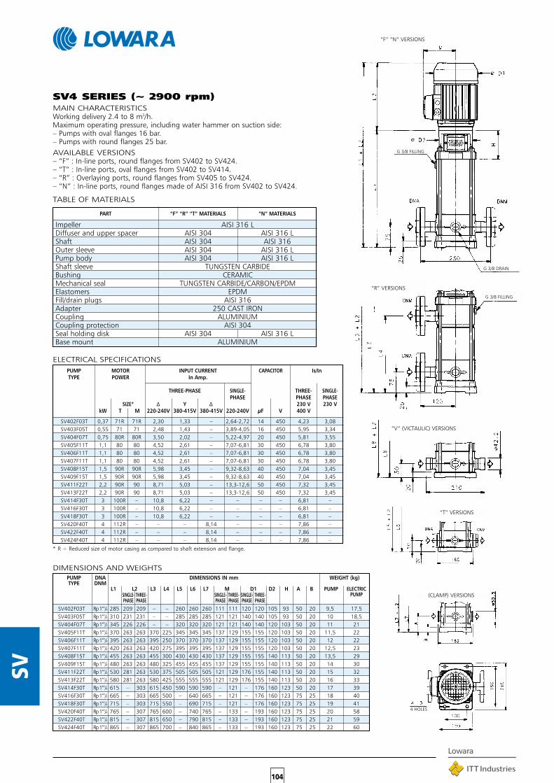
104
SV
SV4 SERIES (~ 2900 rpm)MAIN CHARACTERISTICSWorking delivery 2.4 to 8 m3/h.Maximum operating pressure, including water hammer on suction side:– Pumps with oval flanges 16 bar.– Pumps with round flanges 25 bar.AVAILABLE VERSIONS– “F” : In-line ports, round flanges from SV402 to SV424.– “T” : In-line ports, oval flanges from SV402 to SV414.– “R” : Overlaying ports, round flanges from SV405 to SV424.– “N” : In-line ports, round flanges made of AISI 316 from SV402 to SV424.
SV402F03T 0,37 71R 71R 2,30 1,33 – 2,64-2,72 14 450 4,23 3,08SV403F05T 0,55 71 71 2,48 1,43 – 3,89-4,05 16 450 5,95 3,34SV404F07T 0,75 80R 80R 3,50 2,02 – 5,22-4,97 20 450 5,81 3,55SV405F11T 1,1 80 80 4,52 2,61 – 7,07-6,81 30 450 6,78 3,80SV406F11T 1,1 80 80 4,52 2,61 – 7,07-6,81 30 450 6,78 3,80SV407F11T 1,1 80 80 4,52 2,61 – 7,07-6,81 30 450 6,78 3,80SV408F15T 1,5 90R 90R 5,98 3,45 – 9,32-8,63 40 450 7,04 3,45SV409F15T 1,5 90R 90R 5,98 3,45 – 9,32-8,63 40 450 7,04 3,45SV411F22T 2,2 90R 90 8,71 5,03 – 13,3-12,6 50 450 7,32 3,45SV413F22T 2,2 90R 90 8,71 5,03 – 13,3-12,6 50 450 7,32 3,45SV414F30T 3 100R – 10,8 6,22 – – – – 6,81 –SV416F30T 3 100R – 10,8 6,22 – – – – 6,81 –SV418F30T 3 100R – 10,8 6,22 – – – – 6,81 –SV420F40T 4 112R – – – 8,14 – – – 7,86 –SV422F40T 4 112R – – – 8,14 – – – 7,86 –SV424F40T 4 112R – – – 8,14 – – – 7,86 –
TABLE OF MATERIALS
PART “F” “R” “T” MATERIALS “N” MATERIALS
Impeller AISI 316 LDiffuser and upper spacer AISI 304 AISI 316 LShaft AISI 304 AISI 316Outer sleeve AISI 304 AISI 316 LPump body AISI 304 AISI 316 LShaft sleeve TUNGSTEN CARBIDEBushing CERAMICMechanical seal TUNGSTEN CARBIDE/CARBON/EPDMElastomers EPDMFill/drain plugs AISI 316Adapter 250 CAST IRONCoupling ALUMINIUMCoupling protection AISI 304Seal holding disk AISI 304 AISI 316 LBase mount ALUMINIUM
ELECTRICAL SPECIFICATIONSPUMP MOTOR INPUT CURRENT CAPACITOR Is/InTYPE POWER In Amp.
THREE-PHASE SINGLE- THREE- SINGLE-PHASE PHASE PHASE
SIZE* ∆ Y ∆ 230 V 230 VkW T M 220-240V 380-415V 380-415V 220-240V µF V 400 V
* R = Reduced size of motor casing as compared to shaft extension and flange.
“F” “N” VERSIONS
G 3/8 FILLING
G 3/8 DRAIN
“R” VERSIONS
G 3/8 FILLING
“V” (VICTAULIC) VERSIONS
“T” VERSIONS
4 HOLES
SV402F03T Rp 1”1/4 285 209 209 – – 260 260 260 111 111 120 120 105 93 50 20 9,5 17,5SV403F05T Rp 1”1/4 310 231 231 – – 285 285 285 121 121 140 140 105 93 50 20 10 18,5SV404F07T Rp 1”1/4 345 226 226 – – 320 320 320 121 121 140 140 120 103 50 20 11 21SV405F11T Rp 1”1/4 370 263 263 370 225 345 345 345 137 129 155 155 120 103 50 20 11,5 22SV406F11T Rp 1”1/4 395 263 263 395 250 370 370 370 137 129 155 155 120 103 50 20 12 22SV407F11T Rp 1”1/4 420 263 263 420 275 395 395 395 137 129 155 155 120 103 50 20 12,5 23SV408F15T Rp 1”1/4 455 263 263 455 300 430 430 430 137 129 155 155 140 113 50 20 13,5 29SV409F15T Rp 1”1/4 480 263 263 480 325 455 455 455 137 129 155 155 140 113 50 20 14 30SV411F22T Rp 1”1/4 530 281 263 530 375 505 505 505 121 129 176 155 140 113 50 20 15 32SV413F22T Rp 1”1/4 580 281 263 580 425 555 555 555 121 129 176 155 140 113 50 20 16 33SV414F30T Rp 1”1/4 615 – 303 615 450 590 590 590 – 121 – 176 160 123 50 20 17 39SV416F30T Rp 1”1/4 665 – 303 665 500 – 640 665 – 121 – 176 160 123 75 25 18 40SV418F30T Rp 1”1/4 715 – 303 715 550 – 690 715 – 121 – 176 160 123 75 25 19 41SV420F40T Rp 1”1/4 765 – 307 765 600 – 740 765 – 133 – 193 160 123 75 25 20 58SV422F40T Rp 1”1/4 815 – 307 815 650 – 790 815 – 133 – 193 160 123 75 25 21 59SV424F40T Rp 1”1/4 865 – 307 865 700 – 840 865 – 133 – 193 160 123 75 25 22 60
DIMENSIONS AND WEIGHTSPUMP DNA DIMENSIONS IN mm WEIGHT (kg)TYPE DNM
L1 L2 L3 L4 L5 L6 L7 M D1 D2 H A B PUMP ELECTRICSINGLE- THREE- SINGLE- THREE- SINGLE- THREE- PUMPPHASE PHASE PHASE PHASE PHASE PHASE
(CLAMP) VERSIONS

105
SV
SV4 SERIESOPERATING CHARACTERISTICS AT 2900 rpm 50 Hz
These performances are valid for liquids with density ρ = 1.0 kg/dm3 and kinematic viscosity γ = 1 mm2/sec.
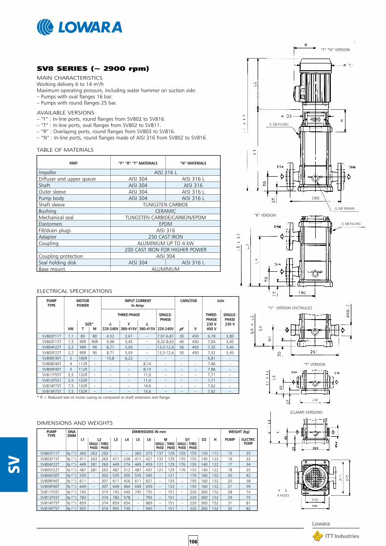
106
SV
SV8 SERIES (~ 2900 rpm)MAIN CHARACTERISTICSWorking delivery 6 to 14 m3/hMaximum operating pressure, including water hammer on suction side:– Pumps with oval flanges 16 bar.– Pumps with round flanges 25 bar.
AVAILABLE VERSIONS– “F” : In-line ports, round flanges from SV802 to SV816.– “T” : In-line ports, oval flanges from SV802 to SV811.– “R” : Overlaying ports, round flanges from SV803 to SV816.– “N” : In-line ports, round flanges made of AISI 316 from SV802 to SV816.
SV802F11T 1,1 80 80 4,52 2,61 – 7,07-6,81 30 450 6,78 3,80SV803F15T 1,5 90R 90R 5,98 3,45 – 9,32-8,63 40 450 7,04 3,45SV804F22T 2,2 90R 90 8,71 5,03 – 13,3-12,6 50 450 7,32 3,45SV805F22T 2,2 90R 90 8,71 5,03 – 13,3-12,6 50 450 7,32 3,45SV806F30T 3 100R – 10,8 6,22 – – – – 6,81 –SV808F40T 4 112R – – – 8,14 – – – 7,86 –SV809F40T 4 112R – – – 8,14 – – – 7,86 –SV811F55T 5,5 132R – – – 11,0 – – – 7,71 –SV812F55T 5,5 132R – – – 11,0 – – – 7,71 –SV814F75T 7,5 132R – – – 14,6 – – – 7,62 –SV816F75T 7,5 132R – – – 14,6 – – – 7,62 –
TABLE OF MATERIALS
PART “F” “R” “T” MATERIALS “N” MATERIALS
Impeller AISI 316 LDiffuser and upper spacer AISI 304 AISI 316 LShaft AISI 304 AISI 316Outer sleeve AISI 304 AISI 316 LPump body AISI 304 AISI 316 LShaft sleeve TUNGSTEN CARBIDEBushing CERAMICMechanical seal TUNGSTEN CARBIDE/CARBON/EPDMElastomers EPDMFill/drain plugs AISI 316Adapter 250 CAST IRONCoupling ALUMINIUM UP TO 4 kW
200 CAST IRON FOR HIGHER POWERCoupling protection AISI 304Seal holding disk AISI 304 AISI 316 LBase mount ALUMINIUM
ELECTRICAL SPECIFICATIONS
PUMP MOTOR INPUT CURRENT CAPACITOR Is/InTYPE POWER In Amp.
THREE-PHASE SINGLE- THREE- SINGLE-PHASE PHASE PHASE
SIZE* ∆ Y ∆ 230 V 230 VkW T M 220-240V 380-415V 380-415V 220-240V µF V 400 V
* R = Reduced size of motor casing as compared to shaft extension and flange.
DIMENSIONS AND WEIGHTS
PUMP DNA DIMENSIONS IN mm WEIGHT (kg)TYPE DNM
L1 L2 L3 L4 L5 L6 M D1 D2 H PUMP ELECTRICSINGLE- THREE- SINGLE- THREE- SINGLE- THREE- PUMPPHASE PHASE PHASE PHASE PHASE PHASE
“F” “N” VERSION
G 3/8 FILLING
G 3/8 SDRAIN
“R” VERSION
G 3/8 FILLING
“V” VERSION (VICTAULIC)
“T” VERSION
4 HOLES
SV802F11T Rp 1”1/2 363 263 263 – – 363 373 137 129 155 155 120 112 15 25SV803F15T Rp 1”1/2 411 263 263 411 236 411 421 137 129 155 155 140 122 16 32SV804F22T Rp 1”1/2 449 281 263 449 274 449 459 121 129 176 155 140 122 17 34SV805F22T Rp 1”1/2 487 281 263 487 312 487 497 121 129 176 155 140 122 18 35SV806F30T Rp 1”1/2 535 – 303 535 350 535 545 – 121 – 176 160 132 20 42SV808F40T Rp 1”1/2 611 – 307 611 426 611 621 – 133 – 193 160 132 20 58SV809F40T Rp 1”1/2 649 – 307 649 464 649 659 – 133 – 193 160 132 21 59SV811F55T Rp 1”1/2 745 – 374 745 540 745 755 – 151 – 220 300 152 28 74SV812F55T Rp 1”1/2 783 – 374 783 578 – 793 – 151 – 220 300 152 29 75SV814F75T Rp 1”1/2 859 – 374 859 654 – 869 – 151 – 220 300 152 31 81SV816F75T Rp 1”1/2 935 – 374 935 730 – 945 – 151 – 220 300 152 32 82
(CLAMP) VERSIONS
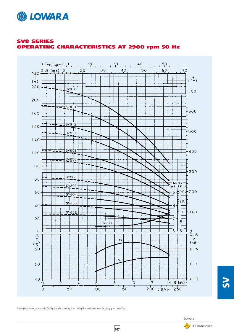
107
SV
SV8 SERIESOPERATING CHARACTERISTICS AT 2900 rpm 50 Hz
These performances are valid for liquids with density ρ = 1.0 kg/dm3 and kinematic viscosity γ = 1 mm2/sec.

108
SV
SV1602F22T Rp 2” 383 281 263 – – – 383 121 129 176 155 140 122 15 32SV1603F30T Rp 2” 431 – 303 – – – 431 – 121 – 176 160 132 16 38SV1604F40T Rp 2” 469 – 307 – – – 469 – 133 – 193 160 132 17,5 55SV1605F55T Rp 2” 527 – 374 – – – 527 – 151 – 220 300 152 22 68SV1606F55T Rp 2” 565 – 374 – – – 565 – 151 – 220 300 152 23 69SV1607F75T Rp 2” 603 – 374 – – – 603 – 151 – 220 300 152 24 74SV1608F75T Rp 2” 641 – 374 – – – – – 151 – 220 300 152 25 75SV1610F110T Rp 2” 749 – 427 – – – 749 – 191 – 257 350 184 34 119SV1612F110T Rp 2” 825 – 427 – – – 825 – 191 – 257 350 184 36 121SV1614F150T Rp 2” 901 – 488 – – – 901 – 232 – 310 350 184 38 130SV1615F150T Rp 2” 939 – 488 – – – 939 – 232 – 310 350 184 39 131
SV16 SERIES (~ 2900 rpm)MAIN CHARACTERISTICSWorking delivery 8 to 24 m3/h.Maximum operating pressure, including water hammer on suction side:– Pumps with round flanges 25 bar.
AVAILABLE VERSIONS– “F” : In-line ports, round flanges from SV1602 to SV1615.– “N” : In-line ports, round flanges in AISI 316 from SV1602 to SV1615.
TABLE OF MATERIALS
PART “F” MATERIALS “N” MATERIALS
Impeller AISI 316 LDiffuser and upper spacer AISI 304 AISI 316 LShaft AISI 304 AISI 316Outer sleeve AISI 304 AISI 316 LPump body AISI 304 AISI 316 LShaft sleeve TUNGSTEN CARBIDEBushing CERAMICMechanical seal TUNGSTEN CARBIDE/CARBON/EPDMElastomers EPDMFill/drain plugs AISI 316Adapter 250 CAST IRONCoupling Aluminium UP TO 4 kW
200 CAST IRON FOR HIGHER POWERCoupling protection AISI 304Seal holding disk AISI 304 AISI 316 LBase mount ALUMINIUM
ELECTRICAL SPECIFICATIONS
PUMP MOTOR INPUT CURRENT CAPACITOR Is/InTYPE POWER In Amp.
THREE-PHASE SINGLE- THREE- SINGLE-PHASE PHASE PHASE
SIZE* ∆ Y ∆ 230 V 230 VkW T M 220-240V 380-415V 380-415V 220-240V µF V 400 V
* R = Reduced size of motor casing as compared to shaft extension and flange.
ELECTRICAL SPECIFICATIONS
PUMP DNA DIMENSIONS IN mm WEIGHT (kg)TYPE DNM
L1 L2 L3 L4 L5 L6 M D1 D2 H PUMP ELECTRICSINGLE- THREE- SINGLE- THREE- SINGLE- THREE- PUMPPHASE PHASE PHASE PHASE PHASE PHASE
“F” “N” VERSIONS
G 3/8 FILLING
G 3/8 DRAIN
“V” VERSION (VICTAULIC)
4 HOLES
SV1602F22T 2,2 90R 90 8,71 5,03 – 13,3-12,6 50 450 7,32 3,45SV1603F30T 3 100R – 10,8 6,22 – – – – 6,81 –SV1604F40T 4 112R – – – 8,14 – – – 7,86 –SV1605F55T 5,5 132R – – – 11,0 – – – 7,71 –SV1606F55T 5,5 132R – – – 11,0 – – – 7,71 –SV1607F75T 7,5 132R – – – 14,6 – – – 7,62 –SV1608F75T 7,5 132R – – – 14,6 – – – 7,62 –SV1610F110T 11 160R – – – 21,2 – – – 8,75 –SV1612F110T 11 160R – – – 21,2 – – – 8,75 –SV1614F150T 15 160 – – – 28,6 – – – 8,56 –SV1615F150T 15 160 – – – 28,6 – – – 8,56 – (CLAMP) VERSIONS

109
SV
SV16 SERIESOPERATING CHARACTERISTICS AT 2900 rpm 50 Hz
These performances are valid for liquids with density ρ = 1.0 kg/dm3 and kinematic viscosity γ = 1 mm2/sec.

110
SV
“F” “N” VERSION
G 1/2 FILLING
G 1/2 DRAIN
4 HOLES
SV3002F40T 65 588 307 105 320 133 193 160 170 48 78SV3003F55T 65 680 374 105 320 151 220 300 190 56 102SV3004F75T 65 752 374 105 320 151 220 300 190 59 109SV3005F110T 65 856 427 105 320 191 257 350 222 70 155SV3006F110T 65 1120 427 105 320 191 257 350 222 83 168SV3007F150T 65 1192 488 105 320 232 310 350 222 86 178SV3008F150T 65 1264 488 105 320 232 310 350 222 89 181SV3009F150T 65 1336 488 105 320 232 310 350 222 93 185SV3010F185T 65 1408 532 105 320 232 310 350 222 96 195SV3011F185T 65 1480 532 105 320 232 310 350 222 99 198SV3012F220T 65 1552 532 105 320 232 310 350 222 102 216
SV30 SERIES (~ 2900 rpm)MAIN CHARACTERISTICSWorking delivery 15 to 39 m3/h.Maximum operating pressure, including water hammer on suction side:– Up to SV3006 16 bar.– From SV3007 to SV3012 25 bar.
AVAILABLE VERSIONS– “F” : In-line ports, round flanges from SV3002 to SV3012.– “N” : In-line ports, round flanges in AISI 316 from SV3002 to SV3012.
TABLE OF MATERIALS
PART “F” MATERIALS “N” MATERIALS
Impeller AISI 316 LDiffuser and upper spacer AISI 316 LShaft AISI 431 AISI 316Outer sleeve AISI 304 AISI 316 LPump body 250 CAST IRON CF - 8M (AISI 316 L)Shaft sleeve TUNGSTEN CARBIDEBushing CERAMICMechanical seal SILICON/CARBIDE/CARBON/EPDMElastomers EPDMFill/drain plugs NICKEL PLATED BRASS AISI 316Spider 250 CAST IRONCoupling 200 CAST IRONCoupling protection AISI 304Seal holding disk – AISI 316 L
ELECTRICAL SPECIFICATIONS
PUMP MOTOR INPUT CURRENT
Is/InTYPE POWER In Amp.
THREE-PHASE
∆ Y ∆kW SIZE* 220-240 V 380-415 V 380-415 V 400 V
* R = Reduced size of motor casing as compared to shaft extension and flange.
DIMENSIONS AND WEIGHTS
PUMP DNA DIMENSIONS IN mm WEIGHT (kg)TYPE DNM
L1 L2 A B M D1 D2 H PUMPELECTRIC
PUMP
SV3002F40T 4 112R – – 8,14 7,86SV3003F55T 5,5 132R – – 11,0 7,71SV3004F75T 7,5 132R – – 14,6 7,62SV3005F110T 11 160R – – 21,2 8,75SV3006F110T 11 160R – – 21,2 8,75SV3007F150T 15 160 – – 28,6 8,56SV3008F150T 15 160 – – 28,6 8,56SV3009F150T 15 160 – – 28,6 8,56SV3010F185T 18,5 160 – – 34,2 8,80SV3011F185T 18,5 160 – – 34,2 8,80SV3012F220T 22 180R – – 40,3 8,61

111
SV
SV30 SERIESOPERATING CHARACTERISTICS AT 2900 rpm 50 Hz
These performances are valid for liquids with density ρ = 1.0 kg/dm3 and kinematic viscosity γ = 1 mm2/sec.
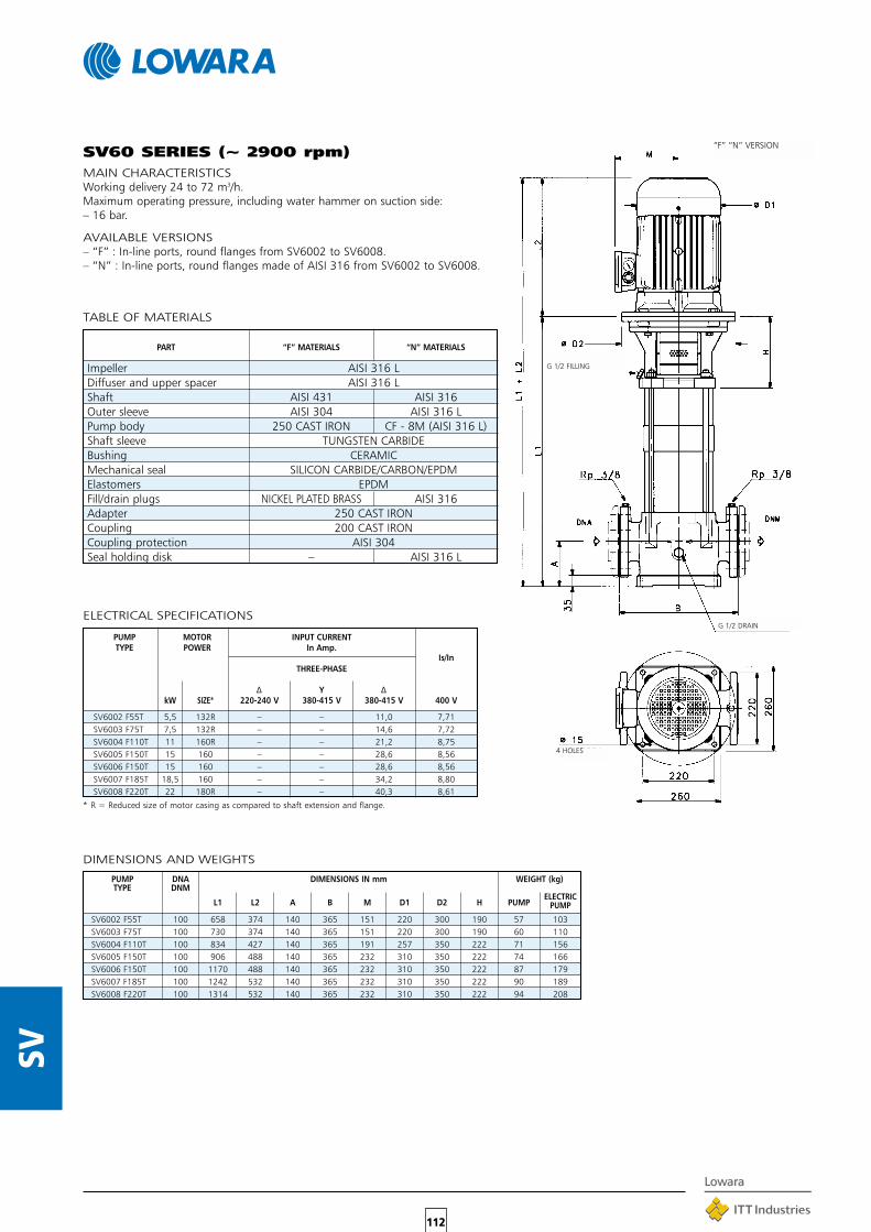
112
SV
SV60 SERIES (~ 2900 rpm)MAIN CHARACTERISTICSWorking delivery 24 to 72 m3/h.Maximum operating pressure, including water hammer on suction side:– 16 bar.
AVAILABLE VERSIONS– “F” : In-line ports, round flanges from SV6002 to SV6008.– “N” : In-line ports, round flanges made of AISI 316 from SV6002 to SV6008.
SV6002 F55T 5,5 132R – – 11,0 7,71SV6003 F75T 7,5 132R – – 14,6 7,72SV6004 F110T 11 160R – – 21,2 8,75SV6005 F150T 15 160 – – 28,6 8,56SV6006 F150T 15 160 – – 28,6 8,56SV6007 F185T 18,5 160 – – 34,2 8,80SV6008 F220T 22 180R – – 40,3 8,61
SV6002 F55T 100 658 374 140 365 151 220 300 190 57 103SV6003 F75T 100 730 374 140 365 151 220 300 190 60 110SV6004 F110T 100 834 427 140 365 191 257 350 222 71 156SV6005 F150T 100 906 488 140 365 232 310 350 222 74 166SV6006 F150T 100 1170 488 140 365 232 310 350 222 87 179SV6007 F185T 100 1242 532 140 365 232 310 350 222 90 189SV6008 F220T 100 1314 532 140 365 232 310 350 222 94 208
TABLE OF MATERIALS
PART “F” MATERIALS “N” MATERIALS
Impeller AISI 316 LDiffuser and upper spacer AISI 316 LShaft AISI 431 AISI 316Outer sleeve AISI 304 AISI 316 LPump body 250 CAST IRON CF - 8M (AISI 316 L)Shaft sleeve TUNGSTEN CARBIDEBushing CERAMICMechanical seal SILICON CARBIDE/CARBON/EPDMElastomers EPDMFill/drain plugs NICKEL PLATED BRASS AISI 316Adapter 250 CAST IRONCoupling 200 CAST IRONCoupling protection AISI 304Seal holding disk – AISI 316 L
ELECTRICAL SPECIFICATIONS
PUMP MOTOR INPUT CURRENT
Is/InTYPE POWER In Amp.
THREE-PHASE
∆ Y ∆kW SIZE* 220-240 V 380-415 V 380-415 V 400 V
* R = Reduced size of motor casing as compared to shaft extension and flange.
DIMENSIONS AND WEIGHTS
PUMP DNA DIMENSIONS IN mm WEIGHT (kg)TYPE DNM
L1 L2 A B M D1 D2 H PUMPELECTRIC
PUMP
“F” “N” VERSION
G 1/2 FILLING
G 1/2 DRAIN
4 HOLES
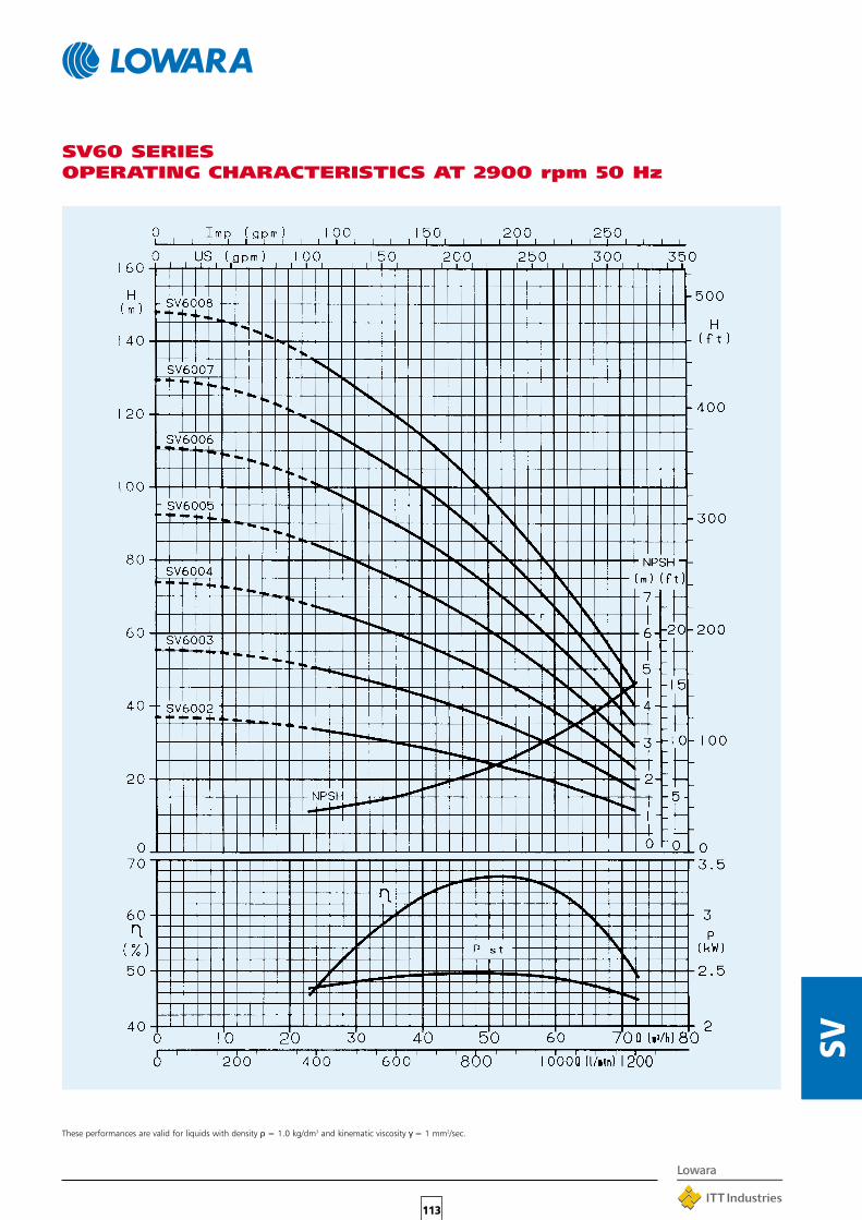
113
SV
SV60 SERIESOPERATING CHARACTERISTICS AT 2900 rpm 50 Hz
These performances are valid for liquids with density ρ = 1.0 kg/dm3 and kinematic viscosity γ = 1 mm2/sec.

APPLICATIONS•Pumping of coolants, lubricants and condensate.
•Machine tools, welders, engine test stands.
•Cooling systems.
•Washing systems.
•Boosters.
•Fire-fighting systems.
SPECIFICATIONS
PUMP
•Delivery: up to 72 m3/h.
•Head: up to 247 m.
•Liquid temperature:-10°C to +90°C for “S” and “N” versions with coupling,-10°C to +60°C for close-coupled “E” versions.
•Maximum ambient temperature: +40°C.
•Tested in compliance with ISO 2548 for class Cstandard pumps.
•Rotation direction: clockwise when looking at pumpend (indicated by the arrow on adapter and coupling).
•Mechanical seal in compliance with DIN 24960and ISO 3069 for “S” and “N” versions, LOWARA sealfor “E” versions. Standard mechanical seal used for cleanliquids. For applications with contaminated liquids thereare available seals in Tungsten/Silicon/FPM or Tungsten Carbide/Silicon/FPM or Silicon/Silicon/FPM.
•Tank coupling flange in compliance with DIN 5440 andEN 12157.
•Standard installation in vertical position: however, allmodels (except the SVI 30 and 60 versions with over 5stages at 50 Hz, and with over 4 stages at 60 Hz) canbe installed horizontally.
•Reduced axial thrust allows standard motors to be used(for “S” and “N” versions).
•These pumps can handle clean liquids free of abrasivesubstances or fibres, with kinematic viscosities up to 37mm2/sec., with suitably sized motor.
•Minimum level of suction liquid: 25mm for SVI 2-4-6-8-16 models and 100 mm for SVI 30 and 60 models.
•Suction base has filter with 2 mm. diameter holes (SVI2-4) or 3 mm. holes (SVI 8-16-30-60).
•AISI 316 STAINLESS STEEL “N” version available formodels SVI 2-4-8-16.
114
SVI
SVI
SVI SERIESSUBMERSIBLE VERTICALELECTRIC PUMPS
•Longer pump columns (from coupling flangeto suction base) are available on request.Possible variants follow the number of upperstages indicated in each model’s dimensionstable.
MOTOR
•Squirrel cage, finned aluminium casing,enclosed construction with externalventilation.
• IP55 protection.
•Class F insulation.
•Performance in compliance with CEI 2-3 (IEC34,1).
•Construction design:- Close-coupled for “E” version (LOWARAmotor);- Standard motor for “S” and “N” V18versions, for power up to 4 kW, and V1versions for power above 4 kW.
•Standard voltage:Single-phase 220-240V - 50 Hz onrequest.Three-phase 220-240/380-415 V - 50 Hzwith power up to 3 kW;380-415 V - 50 Hz with power up above23 kW.

115
SVI
SVI SERIESOPERATING CHARACTERISTICS AT 2900 rpm 50 Hz
MINIMUM IMMERSION LEVEL
These performances are valid for liquids with density ρ = 1.0 kg/dm3 and kinematic viscosity γ = 1 mm2/sec.
SVI 2 25 20 60SVI 4 25 20 60SVI 8 25 35 80SVI 16 25 35 80SVI 30 100 80 120SVI 60 100 80 120
PUMP TYPE DIMENSIONS IN mm DISTANCE FROM THE BOTTOMC D
mmMINIMUM RECOMMENDED

116
DOM
INO
DOMINOSINGLE-PHASE ELECTRICPUMP COMMAND ANDCONTROL EQUIPMENTDomino is a compact and functional devicecontrolled by an electronic circuit, consisting of adiaphragm and retaining spring systemintegrated by delivery and pressure sensors.
It is designed to replace traditional pressureboosting systems for domestic use (consisting ofa pressure switch, expansion tank, pressuregauge and fittings); it offers the advantage ofsmaller overall dimensions and no routinemaintenance is required.
Moreover, Domino provides the electric pumpwith adequate protection against dry running.The starting pressure setting ranges from 1.5 to3 bar.
It can be coupled to single-phase pumps with amaximum input current of 10 A, and developinga head at least 0.5 to 0.7 bar greater than theminimum starting pressure setting.It is made of a non-toxic plastic material suitablefor the handling of drinking water.
APPLICATIONS•Pressure boosting in domestic and civil applications.
•Automatic lawn sprinkler systems.
SPECIFICATIONS•Voltage: 220-240 V single-phase.
•Frequency: 50/60 Hz.
•Maximum current: 10 A.
•IP 65 protection.
•Maximum pressure: 10 bar.
•Adjustable minimum starting pressure:1,5 to 3 bar.
•Differential pressure: 0.5 to 0.7 bar.
•R 1” pump and user connector.
•Maximum liquid temperature: 35° C.
•Non-toxic plastic material, suitable forhandling drinking water.
•Protection against dry running.
•Pressure gauge (0-10 bar).
•Manual reset button.
•Mains power supply (POWER) indicator light(green).
•Pump running (ON) indicator light (yellow).
•Dry running (FAILURE) protection systemactivation indicator light (red).
•Delivery up to 170 l/min. (10 m3/h).
•Low friction loss (see diagram nextpage).
•Approx. overall dimensions:100 x 150 x 200 mm.

117
DOM
INO
INSTALLATION DIAGRAM
MINIMUM STARTING PRESSURE SETTING(1,5 to 3 bar)
FRICTION LOSS
Fig. 1PRESSURE GAUGEASSEMBLY
Fig. 2POSSIBLEINSTALLATIONPOSITIONS
Fig. 3ELECTRICALCONNECTIONDIAGRAM
Fig. 1 Fig. 2
Fig. 3

118
SPHE
RE U
NITS
BLOC
KUN
ITSDO
MIN
OSYS
TEM
SPHERE UNITS, BLOCK UNIT AND DOMINOSYSTEMSMALL, PRESSURE VESSELSFULLY AUTOMATIC FOR WATERSUPPLY BOOSTINGAPPLICATIONSThese units consist of a single-phase electricpump, diaphragm tank, pressure switch, pressuregauge and various connectors.Fully assembled and ready to be connected tothe building’s water systems.
❏ CHOICE OF UNITS WITH PERIPHERAL(PM), SELF-PRIMING (BGM), HORIZONTALSINGLE- (CEAM), DOUBLE- (CAM) ANDMULTIPLE-IMPELLER (HM) CENTRIFUGALPUMPS.
❏ AVAILABILITY OF THE “DOMINO”ELECTROMECHANICAL DEVICE FOR THECONTROL AND COMMAND OF SINGLE-PHASE PUMPS. SEE RELATED SECTION INTHIS CATALOGUE.
APPLICATIONS•Pressure boosting in water systems for domestic use,
lawn sprinkling and washing.
•Handling of non-aggressive liquids in industrial plants.
SPECIFICATIONS•Delivery: up to 110 l/min (6.6 m3/h).
•Head: up to 52 m (5.2 bar).
•220 V, 50 Hz single-phase power supply.
•From 0,30 to 1.10 kW installed power.
•For performance ratings (delivery – head) of thesesingle-pump pressure boosting units, see informationrelating to the electric pump in this catalogue.
AVAILABLE VERSIONS•Sphere unit, electric pump with a 24
litre enamelled steel ball tank (AISI 304stainless steel model available on request).
•Block, electric pump with a 25 litreenamelled steel cylindrical tank.

119
SPHE
RE U
NITS
BLOC
KUN
ITSDO
MIN
OSYS
TEM
Sphere group PM 16 0,30 0,40 2,4 1,4 - 2,8 15 - 28 390 470 635 15
Sphere group PM 30 0,50 0,70 4,0 2,0 - 3,5 20 - 38 390 470 635 17
Sphere group CEAM 70/5 0,55 0,75 4,2 1,8 - 2,8 40 - 80 390 580 720 17
Sphere group CEAM 80/5 0,75 1,00 4,8 1,8 - 2,8 60 - 110 390 580 720 11
Sphere group CAM 70/33 0,75 1,00 5,0 2,4 - 3,8 40 - 80 390 470 720 21
Sphere group CAM 70/45 1,10 1,50 8,1 3,6 - 5,2 40 - 80 390 470 720 25
* Sphere group BGM 5 0,55 0,75 4,0 2,5 - 3,5 18 - 56 390 580 720 17
* Sphere group BGM 7 0,75 1,00 4,8 2,8 - 4,1 12 - 54 390 580 720 18
* Sphere group BGM 9 0,90 1,20 5,6 3,2 - 4,2 22 - 52 390 580 720 20
* Sphere group BGM 11 1,10 1,50 6,8 3,4 - 4,7 20 - 64 390 580 720 23
Block CEAM 70/5 0,55 0,75 4,2 1,8 - 2,8 40 - 80 290 660 610 21
Block CEAM 80/5 0,75 1,00 4,8 1,8 - 2,8 60 - 100 290 660 610 22
Block CAM 70/33 0,75 1,00 5,0 2,4 - 3,8 40 - 80 290 660 610 25
* Block BGM 5 0,55 0,75 4,0 2,5 - 3,5 18 - 56 290 660 610 21
* Block BGM 11 1,10 1,50 6,8 3,4 - 4,7 20 - 64 290 660 610 26
Sphere group 2HM4 0,45 0,6 2,9 2,0 - 3,3 10 - 50 390 470 720 14
Sphere group 2HM5 0,55 0,75 3,6 3,2 - 4,4 10 - 50 390 470 720 15
Sphere group 2HM7 0,75 1 5,0 3,6 - 5,6 10 - 50 390 470 720 15
Sphere group 4HM5 0,55 0,75 3,8 1,8 - 3,0 40 - 95 390 470 720 15
Sphere group 4HM7 0,75 1 5,0 2,4 - 4,0 40 - 95 390 470 720 17
Sphere group 4HM9 0,9 1,2 5,7 2,8 - 5,0 40 - 100 390 470 720 17
TECHNICAL SPECIFICATIONS
UNIT TYPE RATED INPUT PRESSURE CAPACITY APPROX. OVERALL WEIGHTPOWER CURRENT SWITCH SETTING DIMENSIONS in mm
MINOR MAJOR HEIGHTBASE BASE
kW HP A bar l/min kg
* Specially suited for suction from buried tanks or wells.The suction port is threaded Rp 1”1/4 (Rp 1” for PM 16 and PM 30).The delivery port is threaded Rp 1” for all pumps.NB: after the unit has been installed, the diaphragm tank air precharge must be set to a value 0.2 bar lower than the minimum pressure switch set-point.
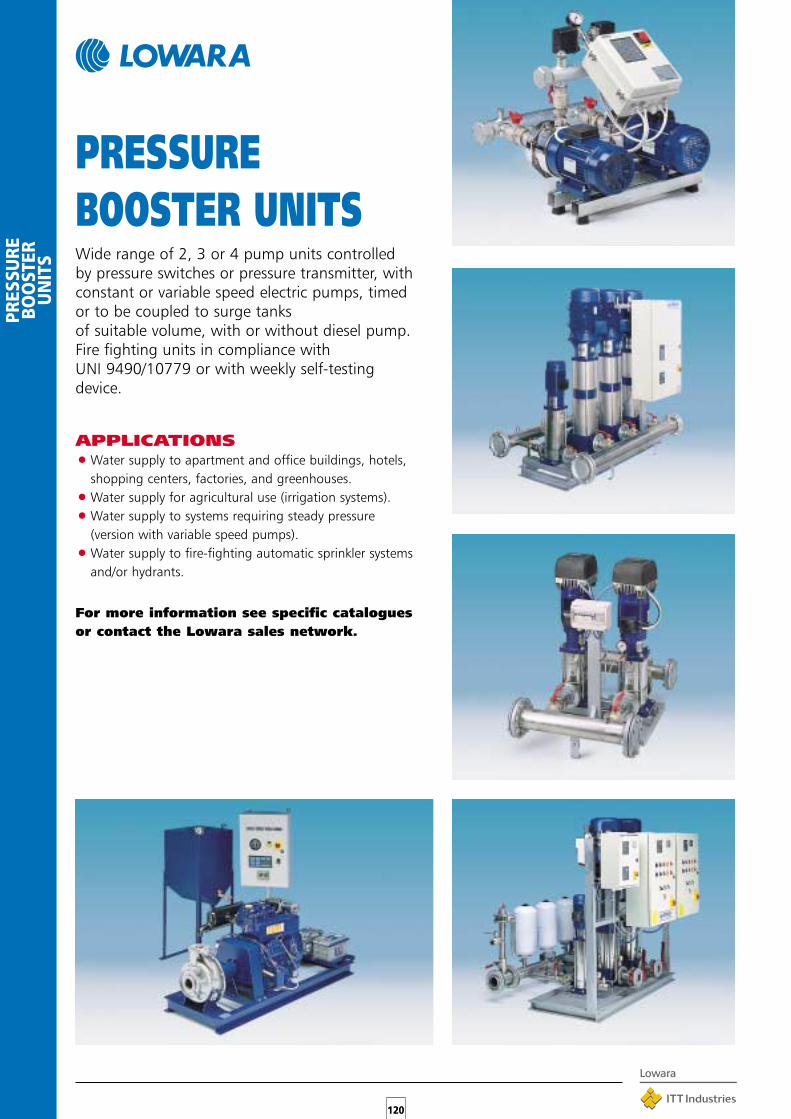
120
PRES
SURE
BOO
STER
UN
ITS
PRESSUREBOOSTER UNITSWide range of 2, 3 or 4 pump units controlledby pressure switches or pressure transmitter, withconstant or variable speed electric pumps, timedor to be coupled to surge tanks of suitable volume, with or without diesel pump.Fire fighting units in compliance with UNI 9490/10779 or with weekly self-testingdevice.
APPLICATIONS•Water supply to apartment and office buildings, hotels,
shopping centers, factories, and greenhouses.
•Water supply for agricultural use (irrigation systems).
•Water supply to systems requiring steady pressure(version with variable speed pumps).
•Water supply to fire-fighting automatic sprinkler systemsand/or hydrants.
For more information see specific cataloguesor contact the Lowara sales network.

121
FIRE
FIG
HTIN
GSY
STEM
❏ FOR FURTHER INFORMATION PLS CONTACTOUR SALES NETWORK.
Fire Fighting Booster Package that utilise the LowaraBorehole range of pumps, the design reduces the spacerequired by traditional packages resulting in a moreeconomical solution.
The system can be installed directly in a tank which is analternative to traditional installations where the pumpsare surface mounted.
SPECIFICATIONS
•Fire Pump Package manufactured to UNI 9490 or UNI10779.
•Number of pumps used 1 service or 1 service 1 jockey.
•Pumps used 4”, 6”, 8”, 10” borehole pumps.
•Maximum power size for service pump 75 kW forservice pump.
•Manifold in painted steel pipe with anchor bolts to fixto a wall or a floor.
•All hydraulic pre-mounted with all requested items inaccordance with UNI 9490/10779.
•Pump connections possible with either flanges orscrewed.
•Complete with valves on delivery side.
FIRE FIGHTINGSYSTEMUNI 9490 OR UNI 10779UTILISINGBOREHOLE PUMPS
CONTROL EQUIPMENT
•Control panel IP54 for installation on wall orcontrol panel frame.
•Pumps controlled by pressure switches.
•Visual display lamps.
•Audible alarm.
OPTIONAL EXTRAS
•12 Volt auxiliary circuit.
•Auto-Test.
•Flow meter.
•Sirens and display light.
•Membrane vessels.

122
FIRE
FIG
HTIN
GSY
STEM
GUDB21/P
Lowara have available 3 versions:
•Hydraulic and electric components on skid.
•Only hydraulic on skid.
•Hydraulic and electric components for installation on a wall.
The fire fighting system shown in the photograph on the previous pageis an example of an installation using 4” pumps.For further information contact your sales support office.

123
FC
FC SERIESIN-LINE ELECTRIC PUMPSIn-line electric pumps with cast iron pump body,AISI 316L stainless steel impeller entirely weldedusing laser technology (for models with 40, 50and 65 nominal port diameter). Suitable forhandling hot or cold moderately aggressiveliquids.
APPLICATIONS•Circulation of hot and cold water for heating and
conditioning systems.
•Water pumping in the civil, industrial and agriculturalsectors.
•Water supply systems in rural applications.
AVAILABLE MODELS•FCE: close-coupled with special motor shaft extension.
•FCS: with stub shaft and standardised motor.
SPECIFICATIONS•Maximum delivery: 190 m3/h.
•Maximum head: 90 m.
•Continuous duty.
•Pumped liquid temperature: -20°C to 130°C.
•Maximum operating pressure: 12 bar (PN 12).
•Port nominal diameter: up to 100 mm.
• Impeller nominal diameter: up to 250 mm.
•Mechanical seal in compliance with (exDIN 24960), lubricated by internalrecirculation of pumped liquid.
•Flanged suction and delivery ports (incompliance with EN 1092-2.
•Bleed valve available on all models.
•IP 55 protection.
•Class F insulation.
•2- and 4-pole versions
•50 and 60 Hz motor frequencies.
•Version with HYDROVAR frequencyconverter (variable speed) available onrequest.
•For in-line twin pumps contact Lowarasales network.
TABLE OF MATERIALS
PART MATERIAL
Pump body 200 CAST IRON (UNI ISO 185)Impeller STAINLESS STEEL*
(AISI 316L - DIN 1.4404)Wear ring
STAINLESS STEELCounterwear ring(AISI 316 - DIN 1.4571)Shaft
Seal housing 200 CAST IRON (UNI ISO 185)Adapter 200 CAST IRON (UNI ISO 185)* *Mechanical seal CERAMIC/CARBON/EPDMO-Rings EPDMFill/drain plugs NICKEL-PLATED BRASSBase (optional) ALUMINIUM
* Cast iron versions: DN 80 and DN 100* * Aluminium versions: 40/50 - 125 2/4 poles
40/50 - 160 2/4 poles
FCE 4 40 - 200 / 40 6 A
IDENTIFICATION CODE
Reduced impeller
6 = 60 Hz
Rated motor power(kW x 10)
Impeller nominal diameter (mm)
Discharge port nominaldiameter (mm)
4 = 4-pole motor
FCE =Motor with specialshaft extension
FCS =Standardised motor withrigid coupling

124
FC
FCE SERIESELECTRICAL SPECIFICATIONS OF MOTORS WITH SPECIALSHAFT EXTENSION
THREE-PHASE 50 Hz 2 POLES MOTORS
THREE-PHASE 50 Hz 4 POLES MOTORS
IEC
SIZE *
CONSTRUCTION
DESIGN
∆ Y ∆ Y Cn
kW 220-240 V 380-415 V 380-415 V 660-690 V rpm ls / ln n % cosϕ Nm Cs/Cn
MOTOR TYPE INPUT CURRENT
In (A)
DATA FOR 400 V 50 Hz
0.75 90R B14 3.72 2.15 - - 2915 8.23 77.7 0.65 2.45 5.20
1.1 90R B14 4.52 2.61 - - 2875 6.78 78.9 0.77 3.65 3.49
1.5 90R B14 5.98 3.45 - - 2875 7.04 80.1 0.78 4.98 3.83
2.2 90R B14 8.71 5.03 - - 2860 7.32 81.1 0.78 7.34 4.12
3 90 B14 10.8 6.22 - - 2845 6.81 80.4 0.87 10.1 3.00
4 112R B14 - - 8.14 4.70 2900 7.86 83.5 0.85 13.2 2.86
5.5 112 B14 - - 11.0 6.35 2910 7.71 84.5 0.85 18.0 2.66
7.5 112 B14 - - 14.6 8.43 2910 7.62 87.2 0.85 24.6 3.03
9.2 132 B14 - - 17.5 10.1 2925 8.72 86.3 0.88 30.0 3.33
11 132 B14 - - 21.2 12.2 2925 8.75 88.8 0.84 35.9 3.66
15 160 B14 - - 28.6 16.5 2940 8.56 85.3 0.89 48.7 3.10
18.5 160 B14 - - 34.2 19.7 2945 8.80 87.3 0.90 60.0 4.06
22 160 B14 - - 40.3 23.3 2945 8.61 89.5 0.88 71.2 4.79
* R = Grandezza cassa motore ridotta rispetto alla sporgenza albero e relativa flangia. fce-mott-2p50_a_te
IEC
SIZE *
CONSTRUCTION
DESIGN
∆ Y ∆ Y Cn
kW 220-240 V 380-415 V 380-415 V 660-690 V rpm ls / ln n % cosϕ Nm Cs/Cn
MOTOR TYPE INPUT CURRENT
In (A)
DATA FOR 400 V 50 Hz
0.25 71 B5 1.71 0.99 - - 1390 3.58 62.0 0.59 1.71 3.16
0.37 71 B5 2.53 1.46 - - 1370 3.39 61.4 0.60 2.57 3.40
0.55 90R B5-B14 3.03 1.75 - - 1390 3.95 68.2 0.67 3.77 2.45
0.75 90R B5 4.04 2.33 - - 1395 4.06 70.1 0.66 5.13 2.73
1.1 90 B5 4.35 2.51 - - 1415 4.65 78.0 0.81 7.42 2.15
1.5 90 B5 5.85 3.38 - - 1420 4.99 79.9 0.80 10.1 2.26
2.2 100 B5 8.28 4.78 - - 1410 5.53 81.4 0.82 14.9 2.52
3 100 B5 11.0 6.37 - - 1425 6.03 82.5 0.82 20.1 2.53
4 112 B5 - - 8.38 4.84 1440 5.81 84.8 0.81 26.5 2.50
5.5 132 B14 - - 11.3 6.52 1445 5.98 85.8 0.82 36.3 2.60
7.5 132 B14 - - 15.2 8.78 1450 6.70 88.1 0.81 49.3 3.17
* R = Grandezza cassa motore ridotta rispetto alla sporgenza albero e relativa flangia. fce-mott-4p50_a_te* R = Reduced size of motor casing as compared to shaft extension and flange.
* R = Reduced size of motor casing as compared to shaft extension and flange.

125
FC
FCS SERIESSTANDARD MOTOR ELECTRICAL SPECIFICATIONS
THREE-PHASE 50 Hz 2 POLES MOTORS
THREE-PHASE 50 Hz 4 POLES MOTORS
IEC
SIZE *
CONSTRUCTION
DESIGN
∆ Y ∆ Y Cn
kW 220-240 V 380-415 V 380-415 V 660-690 V rpm ls / ln n % cosϕ Nm Cs/Cn
MOTOR TYPE INPUT CURRENT
In (A)
DATA FOR 400 V 50 Hz
0.75 80R B5 3.50 2.02 - - 2855 5.81 74.3 0.72 2.51 3.76
1.1 80 B5 4.52 2.61 - - 2875 6.78 78.9 0.77 3.65 3.49
1.5 90R B5 5.98 3.45 - - 2875 7.04 80.1 0.78 4.98 3.83
2.2 90R B5 8.71 5.03 - - 2860 7.32 81.1 0.78 7.34 4.12
3 100R B5 10.8 6.22 - - 2845 6.81 80.4 0.87 10.1 3.00
4 112R B5 - - 8.14 4.70 2900 7.86 83.5 0.85 13.2 2.86
5.5 132R B5 - - 11.0 6.35 2910 7.71 84.5 0.85 18.0 2.66
7.5 132R B5 - - 14.6 8.43 2910 7.62 87.2 0.85 24.6 3.03
11 160R B5 - - 21.2 12.2 2925 8.75 88.8 0.84 35.9 3.66
15 160 B5 - - 28.6 16.5 2940 8.56 85.3 0.89 48.7 3.10
18.5 160 B5 - - 34.2 19.7 2945 8.80 87.3 0.90 60.0 4.06
22 180R B5 - - 40.3 23.3 2945 8.61 89.5 0.88 71.2 4.79
* R = Grandezza cassa motore ridotta rispetto alla sporgenza albero e relativa flangia. fcs-mott-2p50_a_te
IEC
SIZE *
CONSTRUCTION
DESIGN
∆ Y ∆ Y Cn
kW 220-240 V 380-415 V 380-415 V 660-690 V rpm ls / ln n % cosϕ Nm Cs/Cn
MOTOR TYPE INPUT CURRENT
In (A)
DATA FOR 400 V 50 Hz
0.55 80 B5 3.03 1.75 - - 1390 3.95 68.2 0.67 3.77 2.45
0.75 80 B5 4.04 2.33 - - 1395 4.06 70.1 0.66 5.13 2.73
1.1 90 B5 4.35 2.51 - - 1415 4.65 78.0 0.81 7.42 2.15
1.5 90 B5 5.85 3.38 - - 1420 4.99 79.9 0.80 10.1 2.26
2.2 100 B5 8.28 4.78 - - 1410 5.53 81.4 0.82 14.9 2.52
3 100 B5 11.0 6.37 - - 1425 6.03 82.5 0.82 20.1 2.53
4 112 B5 - - 8.38 4.84 1440 5.81 84.8 0.81 26.5 2.50
5.5 132 B5 - - 11.3 6.52 1445 5.98 85.8 0.82 36.3 2.60
7.5 132 B5 - - 15.2 8.78 1450 6.7 88.1 0.81 49.3 3.17
* R = Grandezza cassa motore ridotta rispetto alla sporgenza albero e relativa flangia. fcs-mott-4p50_a_te
* R = Reduced size of motor casing as compared to shaft extension and flange.
* R = Reduced size of motor casing as compared to shaft extension and flange.

126
FC
40-125/07 0,75 1 17,2 15,1 13,6 11,8 9,6 6,9 3,640-125/11 1,1 1,5 22,5 20,2 18,6 16,7 14,5 11,9 8,840-160/15 1,5 2 27,3 24,7 22,9 20,9 18,7 16,1 13,1 9,340-160/22 2,2 3 35,5 32,5 31 29 26,5 24 21 17,740-200/40A* 4 5,5 42,5 39 36,5 34 31 2740-200/40 4 5,5 51 47 44,5 41,5 38,5 35 30,540-200/55 5,5 7,5 62 57,5 54,5 51,5 48 44 39,540-250/75 7,5 10 75,5 71 68,5 65 61,5 57,5 5340-250/110 11 15 85 80,5 78 75 71 67 62 56,550-125/11 1,1 1,5 16,4 13,9 13 12 11 9,7 8,4 7 3,750-125/15 1,5 2 20,5 18 17 16 14,9 13,7 12,3 10,9 7,850-160/22 2,2 3 26 24 23 22 21 20 18,8 17,5 14,750-160/30 3 4 33 30,5 29,5 28,5 27 26 24,5 23 20 1350-160/40 4 5,5 38 36 35 34 33 31,5 30 28,5 25 17,550-200/55 5,5 7,5 47 43,5 42 41 39,5 38 36 34,5 30,550-200/75 7,5 10 56 52 51 49,5 48 46,5 45 43,5 39,550-250/* * 11 15 63 59,5 58 57 55 54 52 50,5 46,5 3850-250/110 11 15 69,5 65,5 64 63 61 60 58,5 56,5 53,5 4550-250/150 15 20 83 79,5 78 76,5 75 73,5 72 70 66 56,565-125/22 2,2 3 18,8 16,4 16 15,4 14,3 11,4 7,965-125/30 3 4 23 20,3 20 19,5 18,1 15,2 11,665-125/40 4 5,5 26,5 24,5 24,5 24 22,5 19,7 16,3 12,265-160/55 5,5 7,5 35 32,5 32 31,5 30 27 23,5 1965-160/75 7,5 10 42,5 40 39,5 38,5 37,5 34 30 2565-200/* * 11 15 53 47,5 47 46 44 40 35 28,565-200/110 11 15 61 55,5 54 53 51,5 47 42 3665-250/150 15 20 70 66,5 65,5 64,5 63 59 54 49 4365-250/185 18,5 25 80 75,5 75 74 72 68 63 57,5 51,565-250/220 22 30 89 84,5 83,5 82,5 80,5 76,5 71,5 66 60 52,580-125/30 3 4 15,5 14,5 13,5 12,5 11 980-125/40 4 5,5 19 18 17 16 14 12,5 11,580-125/55 5,5 7,5 23 21,5 20,5 19,5 18 16,5 14,580-160/75 7,5 10 28 26,5 25,5 24,5 23,5 22,5 2180-200/110 11 15 41 37 35 33 30,5 28 24,5 20,580-200/150 15 20 49,5 46,5 45 43 41 39 36,5 3380-200/185 18,5 25 57 53,5 51,5 50 48 46 43,5 4180-200/220 22 30 65 61 59,5 57,5 55,5 53 51 48 45100-160/110 11 15 29 28 27,5 26,5 25,5 24,5 23 19,5100-200/185 18,5 25 45 41 39,5 38 37 35 32 30,5 25100-200/220 22 30 53 49,5 48 47 45 44 42,5 38,5 33,5 31
Q = DELIVERY
l/min 0 100 150 200 250 300 350 400 450 500 600 800 1000 1200 1400 1600 1800 2000 2500 3000
m3/h 0 6 9 12 15 18 21 24 27 30 36 48 60 72 84 96 108 120 150 180
H = TOTAL HEAD METERS COLUMN OF WATER
FCE - FCS SERIESHYDRAULIC PERFORMANCE TABLE 50 Hz, 2 POLES
Performances in compliance with ISO 9906 – Annex A
*.../40A for FCE version, .../30 for FCS version
* *.../92 for FCE version, .../110A for FCS version
PUMPE TYPE POWER
kW HP
3200
192

127
FC
40-125/02A 0,25 0,33 4,7 4,3 4 3,6 3 2,4 1,740-125/02 0,25 0,33 5,8 5,3 4,9 4,5 4 3,3 2,640-160/02 0,25 0,33 7,1 6,4 6 5,5 5 4,3 3,6 2,640-160/03 0,37 0,5 8,9 8,2 7,7 7,2 6,7 6 5,2 4,440-200/05 0,55 0,75 12,4 11,5 10,8 10,1 9,2 8,2 7,140-200/07 0,75 1 15 13,8 13 12,2 11,3 10,3 9,1 7,940-250/11 1,1 1,5 18,6 17,3 16,5 15,7 14,8 13,8 12,8 11,640-250/15 1,5 2 21 19,8 19 18,2 17,4 16,4 15,4 14,350-125/02 0,25 0,33 6,2 5,5 5,7 5 4,6 4,3 3,6 2,7 1,850-125/03 0,37 0,5 8,1 7,4 7,6 6,8 6,5 6,1 5,3 4,4 3,5 2,550-160/05 0,55 0,75 9,4 8,8 9 8,2 7,9 7,6 6,8 5,9 4,9 3,9 2,750-200/07 0,75 1 11,4 10,5 10,3 9,9 9,5 9,1 8,2 7,1 5,6 3,750-200/11 1,1 1,5 13,6 12,6 12,4 12 11,6 11,2 10,3 9,2 7,8 5,950-250/15 1,5 2 17 15,9 15,6 15,2 14,8 14,4 13,5 12,6 11,5 10,1 8,7 750-250/22 2,2 3 20,2 19 18,6 18,2 17,8 17,4 16,5 15,5 14,4 13 11,5 9,965-125/03 0,37 0,5 5,6 4,9 4,6 4,3 3,9 3,5 3,1 2,6 1,665-125/05 0,55 0,75 6,7 5,9 5,7 5,4 5,1 4,7 4,3 3,9 2,865-160/07 0,75 1 8,6 7,8 7,6 7,2 6,8 6,4 5,9 5,4 4,365-160/11 1,1 1,5 10,4 9,7 9,4 9 8,6 8,2 7,7 7,2 5,9 3,165-200/15 1,5 2 14,7 13,2 12,7 12,2 11,6 11 10,4 9,7 8,165-250/22 2,2 3 19 17,6 17 16,5 16 15,4 14,8 14,1 12,7 965-250/30 3 4 21,5 20,1 19,7 19,2 18,7 18 17,4 16,6 15,1 11,780-125/07 0,75 1 5,6 5,2 5,1 5 4,8 4,6 4,3 3,3 2,280-125/11 1,1 1,5 6,8 6,4 6,3 6,2 6,1 5,9 5,7 4,8 3,8 2,580-200/15 1,5 2 10,5 9,6 9,4 9,2 9 8,7 8,2 6,7 4,780-200/22 2,2 3 13,7 12,7 12,5 12,3 12,1 11,9 11,3 10 7,9 5,580-200/30 3 4 15,8 14,7 14,5 14,3 14,1 13,9 13,3 12 10,3 8,180-250/40 4 5,5 19,9 18,7 18,5 18,3 18 17,6 17 15,5 13,6 11,3 8,480-250/55 5,5 7,5 23,2 22 21,8 21,5 21,3 21 20,3 18,9 17 14,8 12100-160/15 1,5 2 7,8 7,4 7,2 6,8 6,3 5,6 4,9 4 3100-200/22 2,2 3 10,5 9,6 9,3 8,7 8 7,1 6 4,9 3,5 2100-200/30 3 4 12,8 11,8 11,5 11 10,2 9,4 8,3 7,1 5,8 4,3100-250/40 4 5,5 17 15,8 15,5 14,8 13,9 12,9 11,8 10,4 9,2 7,8100-250/55 5,5 7,5 20,5 19,2 19 18,2 17,5 16,5 15,4 14,3 13,2 11,8 8100-250/75 7,5 10 24 22,8 22,5 21,8 21 20,3 19,3 18,3 17,2 15,9 11,9 10
FCE - FCS SERIESHYDRAULIC PERFORMANCE TABLE 50 Hz, 4 POLES
PUMP TYPE POWER
kW HP
Q = DELIVERY
l/min 0 50 75 100 125 150 175 200 250 300 350 400 450 500 600 800 1000 1200 1400 1600
m3/h 0 3 4,5 6 7,5 9 10,5 12 15 18 21 24 27 30 36 48 60 72 84 96
H = TOTAL HEAD METERS COLUMN OF WATER
1800 2000 2500 2700
108 120 150 162
Performances in compliance with ISO 9906 – Annex A

128
FC
FC 40 SERIESOPERATING CHARACTERISTICS AT 2900 rpm 50 Hz, 2 POLES
Please verify with the price list the availability of model type FCE-FCS
These performances are valid for liquids with density ρ = 1.0 kg/dm3 and kinematic viscosity γ = 1 mm2/sec.
* /40A - 4 kW - 4 kW - 5,5 HP for FCE version - /30 - 3kW - 4 HP for FCS version

129
FC
FC 50 SERIESOPERATING CHARACTERISTICS AT 2900 rpm 50 Hz, 2 POLES
Please verify with the price list the availability of model type FCE-FCS
These performances are valid for liquids with density ρ = 1.0 kg/dm3 and kinematic viscosity γ = 1 mm2/sec.
** /92 - 9,2 kW - 12,5 HP for FCE version – /110A - 11 kW - 15 HP for FCS version

130
FC
FC 65 SERIESOPERATING CHARACTERISTICS AT 2900 rpm 50 Hz, 2 POLES
Please verify with the price list the availability of model type FCE-FCS
These performances are valid for liquids with density ρ = 1.0 kg/dm3 and kinematic viscosity γ = 1 mm2/sec.
* 92/ - 9,2 kW - 12,5 HP for FCE version - /110A - 11 kW - 15 HP for FCS version
*
*

131
FC
FC 80 SERIESOPERATING CHARACTERISTICS AT 2900 rpm 50 Hz, 2 POLES
Please verify with the price list the availability of model type FCE-FCS
These performances are valid for liquids with density ρ = 1.0 kg/dm3 and kinematic viscosity γ = 1 mm2/sec.
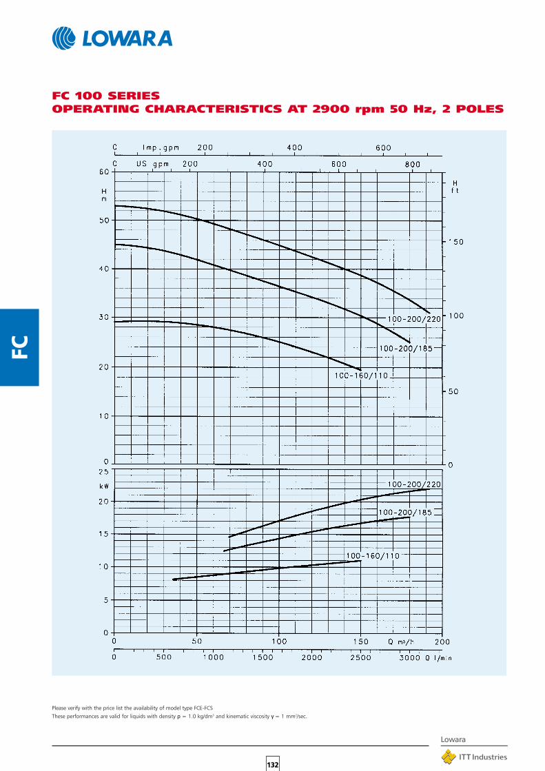
132
FC
FC 100 SERIESOPERATING CHARACTERISTICS AT 2900 rpm 50 Hz, 2 POLES
Please verify with the price list the availability of model type FCE-FCS
These performances are valid for liquids with density ρ = 1.0 kg/dm3 and kinematic viscosity γ = 1 mm2/sec.

133
FC
FC4 40 SERIESOPERATING CHARACTERISTICS AT 1450 rpm 50 Hz, 4 POLES
Please verify with the price list the availability of model type FCE-FCS
These performances are valid for liquids with density ρ = 1.0 kg/dm3 and kinematic viscosity γ = 1 mm2/sec.

134
FC
FC4 50 SERIESOPERATING CHARACTERISTICS AT 1450 rpm 50 Hz, 4 POLES
Please verify with the price list the availability of model type FCE-FCS
These performances are valid for liquids with density ρ = 1.0 kg/dm3 and kinematic viscosity γ = 1 mm2/sec.

135
FC
FC4 65 SERIESOPERATING CHARACTERISTICS AT 1450 rpm 50 Hz, 4 POLES
Please verify with the price list the availability of model type FCE-FCS
These performances are valid for liquids with density ρ = 1.0 kg/dm3 and kinematic viscosity γ = 1 mm2/sec.

136
FC
FC4 80 SERIESOPERATING CHARACTERISTICS AT 1450 rpm 50 Hz, 4 POLES
Please verify with the price list the availability of model type FCE-FCS
These performances are valid for liquids with density ρ = 1.0 kg/dm3 and kinematic viscosity γ = 1 mm2/sec.
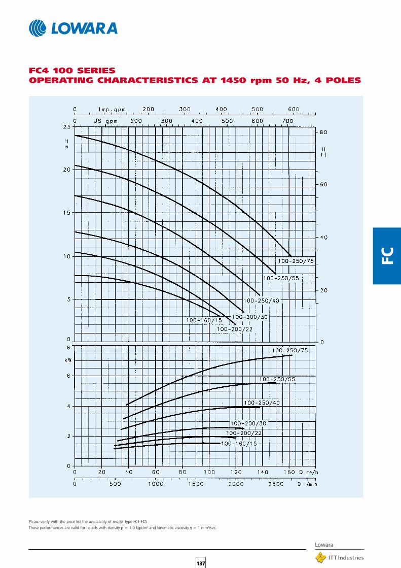
137
FC
FC4 100 SERIESOPERATING CHARACTERISTICS AT 1450 rpm 50 Hz, 4 POLES
Please verify with the price list the availability of model type FCE-FCS
These performances are valid for liquids with density ρ = 1.0 kg/dm3 and kinematic viscosity γ = 1 mm2/sec.

138
FC
CLEARANCE FOR DISASSEMBLY
PUMP BODYWITHOUT FOOT
PUMP TYPE PUMP B H L k WEIGHT
DNM DNA a e h1 h2 x b1 p max kgFCE 40-125/07 40 40 70 70 160 160 129 116 155 243 320 448 86FCE 40-125/11 40 40 70 70 160 160 129 116 155 243 320 448 86FCE 40-160/15 40 40 70 70 160 160 129 116 155 243 320 448 86FCE 40-160/22 40 40 70 70 160 160 129 116 155 243 320 448 86FCE 40-220/40A 40 40 95 65 220 220 133 163 193 502 440 548 98FCE 40-200/40 40 40 95 65 220 220 133 163 193 502 440 548 98FCE 40-200/55 40 40 95 65 220 220 151 163 220 325 440 548 98FCE 40-250/75 40 40 95 65 220 220 151 163 220 325 440 548 98FCE 40-250/110 40 40 95 65 220 220 191 163 257 354 440 599 98FCE 50-125/11 50 50 69 73 170 170 129 122 155 243 340 457 88FCE 50-125/15 50 50 69 73 170 170 129 122 155 243 340 457 88FCE 50-160/22 50 50 69 73 170 170 129 122 155 243 340 457 88FCE 50-160/30 50 50 69 73 170 170 121 122 176 236 340 475 88FCE 50-160/40 50 50 69 73 170 170 133 122 193 247 340 501 88FCE 50-200/55 50 50 110 73 220 220 151 163 220 326 440 577 100FCE 50-200/75 50 50 110 73 220 220 151 163 220 326 440 577 100FCE 50-200/92 50 50 110 73 220 220 191 163 257 354 440 628 100FCE 50-250/110 50 50 110 73 220 220 191 163 257 354 440 628 100FCE 50-250/150 50 50 110 73 220 220 232 163 310 395 440 712 100FCE 65-125/22 65 65 77 83 170 170 129 137 155 274 340 476 92FCE 65-125/30 65 65 77 83 170 170 121 137 176 274 340 494 92FCE 65-125/40 65 65 77 83 170 170 133 137 193 274 340 520 92FCE 65-160/55 65 65 77 83 170 170 151 137 220 288 340 566 92FCE 65-160/75 65 65 77 83 170 170 151 137 220 288 340 566 92FCE 65-200/92 65 65 119 83 237,5 237,5 191 172 257 354 475 633 104FCE 65-200/110 65 65 119 83 237,5 237,5 191 172 257 354 475 633 104FCE 65-250/150 65 65 119 83 237,5 237,5 232 172 310 395 475 717 104FCE 65-250/185 65 65 119 83 237,5 237,5 232 172 310 395 475 761 104FCE 65-250/220 65 65 119 83 237,5 237,5 232 172 310 395 475 761 104FCE 80-125/30 80 80 90 90 175 185 121 148 176 287 360 528 102FCE 50-125/40 80 80 90 90 175 185 133 148 193 287 360 554 102FCE 80-125/55 80 80 90 90 175 185 151 148 220 290 360 600 102FCE 80-160/75 80 80 90 90 175 185 151 148 220 290 360 600 102FCE 80-200/110 80 80 130 90 250 250 191 184 257 354 500 660 112FCE 80-200/150 80 80 130 90 250 250 232 184 310 395 500 788 112FCE 80-200/185 80 80 130 90 250 250 232 184 310 395 500 788 112FCE 80-200/220 80 80 130 90 250 250 232 184 310 395 500 788 112FCE 100-160/110 100 100 105 105 225 191 172 257 – 330 450 675 117FCE 100-200/185 100 100 140 105 275 275 232 196 310 398 550 809 129FCE 100-200/220 100 100 140 105 275 275 232 196 310 398 550 809 129
272931336565727699323537394772799399
123454756656996
10513014015459697781
11214015516598
155169
DIMENSIONS AND WEIGHTS, FCE SERIES
(1) R 1/8 AIR VALVE(2) R 3/8 PRESSURE INTAKE(3) G 3/8 DRAIN
FLANGES
DN D M GHOLES MAX.
N° Ø THICKNESS
32 140 100 78 4 18 18
40 150 110 88 4 18 18
50 165 125 102 4 18 20
65 185 145 122 4 18 20
80 200 160 138 8 18 22
100 220 180 158 8 18 22

139
FCPUMP TYPE PUMP B H L k WEIGHT
DNM DNA a e h1 h2 x b1 p max kgFCE4 40-125/02A 40 40 70 70 160 160 121 116 140 235 320 416 86FCE4 40-125/02 40 40 70 70 160 160 121 116 140 235 320 416 86FCE4 40-160/02 40 40 70 70 160 160 121 116 140 235 320 416 86FCE4 40-160/03 40 40 70 70 160 160 121 116 140 235 320 416 86FCE4 40-200/05 40 40 95 65 220 220 129 163 155 325 440 458 98FCE4 40-200/07 40 40 95 65 220 220 129 163 155 325 440 458 98FCE4 40-250/11 40 40 95 65 220 220 121 163 176 325 440 476 98FCE4 40-250/15 40 40 95 65 220 220 121 163 176 325 440 476 98FCE4 50-125/02 50 50 69 73 170 170 121 122 140 236 340 425 88FCE4 50-125/03 50 50 69 73 170 170 121 122 140 236 340 425 88FCE4 50-160/05 50 50 69 73 170 170 129 122 155 243 340 457 88FCE4 50-200/07 50 50 110 73 220 220 129 163 155 326 440 487 100FCE4 50-200/11 50 50 110 73 220 220 121 163 176 326 440 505 100FCE4 50-250/15 50 50 110 73 220 220 121 163 176 326 440 505 100FCE4 50-250/22 50 50 110 73 220 220 133 163 193 326 440 531 100FCE4 65-125/03 65 65 77 83 170 170 121 137 140 274 340 444 92FCE4 65-125/05 65 65 77 83 170 170 129 137 155 274 340 476 92FCE4 65-160/07 65 65 77 83 170 170 129 137 155 274 340 476 92FCE4 65-160/11 65 65 77 83 170 170 121 137 176 274 340 494 92FCE4 65-200/15 65 65 119 83 237,5 237,5 121 172 176 335 475 510 104FCE4 65-250/22 65 65 119 83 237,5 237,5 133 172 193 335 475 536 104FCE4 65-250/30 65 65 119 83 237,5 237,5 133 172 193 335 475 536 104FCE4 80-125/07 80 80 90 90 175 185 129 148 155 287 360 510 102FCE4 80-125/11 80 80 90 90 175 185 121 148 176 287 360 528 102FCE4 80-200/15 80 80 130 90 250 250 121 184 176 347 500 537 112 75FCE4 80-200/22 80 80 130 90 250 250 133 184 193 347 500 563 112FCE4 80-200/30 80 80 130 90 250 250 133 184 193 347 500 563 112FCE4 80-250/40 80 80 130 90 250 250 151 184 220 347 500 586 112FCE4 80-250/55 80 80 130 90 250 250 191 184 257 354 500 622 112FCE4 100-160/15 100 100 105 105 225 225 121 172 176 311 450 552 117FCE4 100-200/22 100 100 140 105 275 275 133 196 193 362 550 584 129FCE4 100-200/30 100 100 140 105 275 275 133 196 193 362 550 584 129FCE4 100-250/40 100 100 140 105 275 275 151 196 220 362 550 607 129FCE4 100-250/55 100 100 140 105 275 275 191 196 257 362 550 643 129FCE4 100-250/75 100 100 140 105 275 275 191 196 257 362 550 681 129
242425264343454524242743495160333636436064756064
71801031086493100105108111
DIMENSIONS AND WEIGHTS, FCE4 SERIES
(1) R 1/8 AIR VALVE(2) R 3/8 PRESSURE(3) G 3/8 DRAIN
FLANGES
DN D M GHOLES MAX.
N° Ø THICKNESS
32 140 100 78 4 18 18
40 150 110 88 4 18 18
50 165 125 102 4 18 20
65 185 145 122 4 18 20
80 200 160 138 8 18 22
100 220 180 158 8 18 22
PUMP BODYWITHOUT FOOT
CLEARANCE FOR DISASSEMBLY
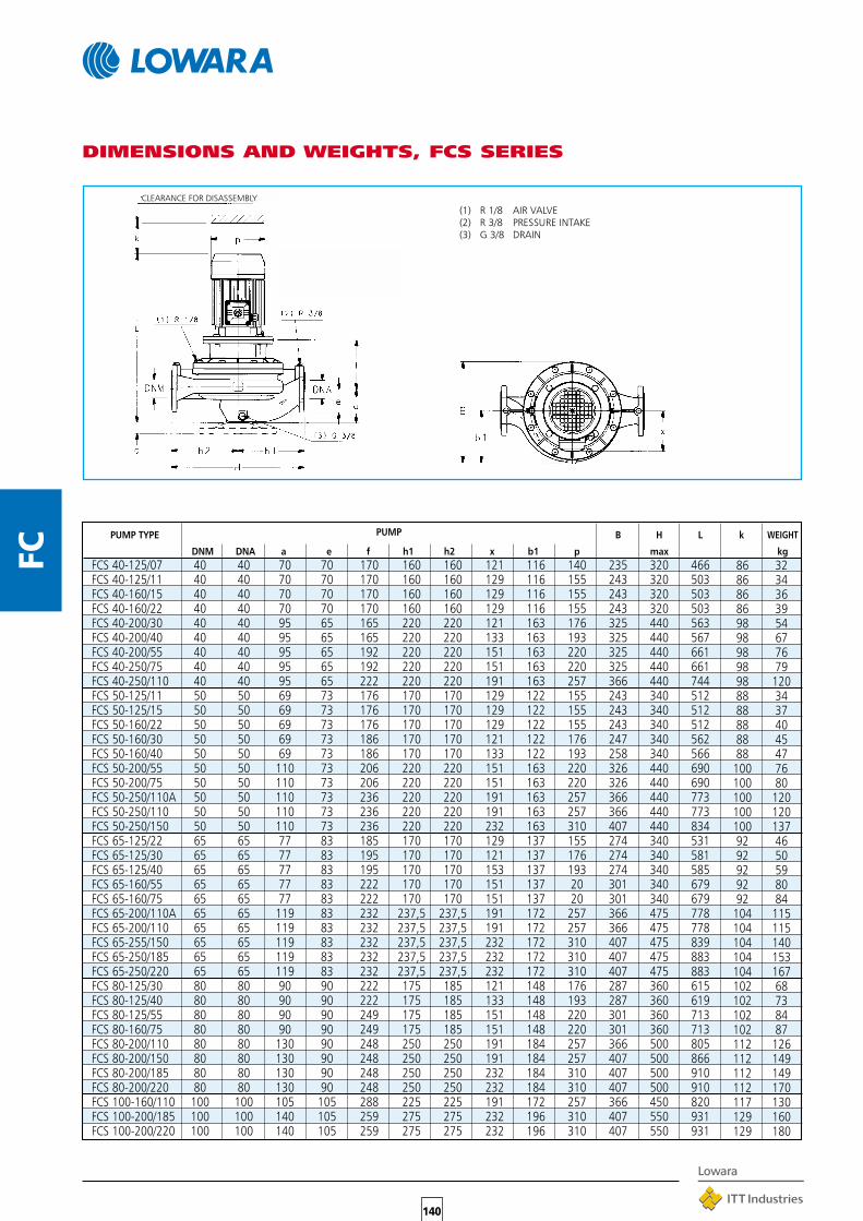
140
FC
CLEARANCE FOR DISASSEMBLY
86 3286 3486 3686 3998 5498 6798 7698 7998 12088 3488 3788 4088 4588 47100 76100 80100 120100 120100 13792 4692 5092 5992 8092 84104 115104 115104 140104 153104 167102 68102 73102 84102 87112 126112 149112 149112 170117 130129 160129 180
PUMP TYPE PUMP B H L k WEIGHT
DNM DNA a e f h1 h2 x b1 p max kgFCS 40-125/07 40 40 70 70 170 160 160 121 116 140 235 320 466FCS 40-125/11 40 40 70 70 170 160 160 129 116 155 243 320 503FCS 40-160/15 40 40 70 70 170 160 160 129 116 155 243 320 503FCS 40-160/22 40 40 70 70 170 160 160 129 116 155 243 320 503FCS 40-200/30 40 40 95 65 165 220 220 121 163 176 325 440 563FCS 40-200/40 40 40 95 65 165 220 220 133 163 193 325 440 567FCS 40-200/55 40 40 95 65 192 220 220 151 163 220 325 440 661FCS 40-250/75 40 40 95 65 192 220 220 151 163 220 325 440 661FCS 40-250/110 40 40 95 65 222 220 220 191 163 257 366 440 744FCS 50-125/11 50 50 69 73 176 170 170 129 122 155 243 340 512FCS 50-125/15 50 50 69 73 176 170 170 129 122 155 243 340 512FCS 50-160/22 50 50 69 73 176 170 170 129 122 155 243 340 512FCS 50-160/30 50 50 69 73 186 170 170 121 122 176 247 340 562FCS 50-160/40 50 50 69 73 186 170 170 133 122 193 258 340 566FCS 50-200/55 50 50 110 73 206 220 220 151 163 220 326 440 690FCS 50-200/75 50 50 110 73 206 220 220 151 163 220 326 440 690FCS 50-250/110A 50 50 110 73 236 220 220 191 163 257 366 440 773FCS 50-250/110 50 50 110 73 236 220 220 191 163 257 366 440 773FCS 50-250/150 50 50 110 73 236 220 220 232 163 310 407 440 834FCS 65-125/22 65 65 77 83 185 170 170 129 137 155 274 340 531FCS 65-125/30 65 65 77 83 195 170 170 121 137 176 274 340 581FCS 65-125/40 65 65 77 83 195 170 170 153 137 193 274 340 585FCS 65-160/55 65 65 77 83 222 170 170 151 137 20 301 340 679FCS 65-160/75 65 65 77 83 222 170 170 151 137 20 301 340 679FCS 65-200/110A 65 65 119 83 232 237,5 237,5 191 172 257 366 475 778FCS 65-200/110 65 65 119 83 232 237,5 237,5 191 172 257 366 475 778FCS 65-255/150 65 65 119 83 232 237,5 237,5 232 172 310 407 475 839FCS 65-250/185 65 65 119 83 232 237,5 237,5 232 172 310 407 475 883FCS 65-250/220 65 65 119 83 232 237,5 237,5 232 172 310 407 475 883FCS 80-125/30 80 80 90 90 222 175 185 121 148 176 287 360 615FCS 80-125/40 80 80 90 90 222 175 185 133 148 193 287 360 619FCS 80-125/55 80 80 90 90 249 175 185 151 148 220 301 360 713FCS 80-160/75 80 80 90 90 249 175 185 151 148 220 301 360 713FCS 80-200/110 80 80 130 90 248 250 250 191 184 257 366 500 805FCS 80-200/150 80 80 130 90 248 250 250 191 184 257 407 500 866FCS 80-200/185 80 80 130 90 248 250 250 232 184 310 407 500 910FCS 80-200/220 80 80 130 90 248 250 250 232 184 310 407 500 910FCS 100-160/110 100 100 105 105 288 225 225 191 172 257 366 450 820FCS 100-200/185 100 100 140 105 259 275 275 232 196 310 407 550 931FCS 100-200/220 100 100 140 105 259 275 275 232 196 310 407 550 931
DIMENSIONS AND WEIGHTS, FCS SERIES
(1) R 1/8 AIR VALVE(2) R 3/8 PRESSURE INTAKE(3) G 3/8 DRAIN

141
FC
PUMP TYPE PUMP B H L k WEIGHT
DNM DNA a e f h1 h2 x b1 p max kg
FCS4 40-200/05 40 40 95 65 155 220 220 129 163 155 325 440 513FCS4 40-200/07 40 40 95 65 155 220 220 129 163 155 325 440 513FCS4 40-250/11 40 40 95 65 155 220 220 121 163 176 325 440 531FCS4 40-250/15 40 40 95 65 155 220 220 121 163 176 325 440 531FCS4 50-200/07 50 50 110 73 169 220 220 129 163 155 326 440 542FCS4 50-200/11 50 50 110 73 169 220 220 121 163 176 326 440 560FCS4 50-250/15 50 50 110 73 169 220 220 121 163 176 326 440 560FCS4 50-250/22 50 50 110 73 179 220 220 133 163 193 326 440 596FCS4 65-160/07 65 65 77 83 185 170 170 129 137 155 274 340 531FCS4 65-160/11 65 65 77 83 185 170 170 121 137 176 274 340 549FCS4 65-200/15 65 65 119 83 165 237,5 237,5 121 172 176 335 475 565FCS4 65-250/22 65 65 119 83 175 237,5 237,5 133 172 193 335 475 601FCS4 65-250/30 65 65 119 83 175 237,5 237,5 133 172 193 335 475 601FCS4 80-125/07 80 80 90 90 212 175 185 129 148 155 287 360 565FCS4 80-125/11 80 80 90 90 212 175 185 121 148 176 287 360 583FCS4 80-200/15 80 80 130 90 181 250 250 121 184 176 347 500 592FCS4 80-200/22 80 80 130 90 191 250 250 133 184 193 347 500 628FCS4 80-200/30 80 80 130 90 191 250 250 133 184 193 347 500 628FCS4 80-250/40 80 80 130 90 191 250 250 151 184 220 347 500 651FCS4 80-250/55 80 80 130 90 218 250 250 191 184 257 354 500 714FCS4 100-160/15 100 100 105 105 221 225 225 121 172 176 311 450 607FCS4 100-200/22 100 100 140 105 202 275 275 133 196 193 362 550 649FCS4 100-200/30 100 100 140 105 202 275 275 133 196 193 362 550 649FCS4 100-250/40 100 100 140 105 202 275 275 151 196 220 362 550 672FCS4 100-250/55 100 100 140 105 229 275 275 191 196 257 362 550 735FCS4 100-250/75 100 100 140 105 229 275 275 191 196 257 362 550 773
DIMENSIONS AND WEIGHTS, FCS4 SERIES
98 5098 5298 5398 53100 44100 51100 63100 6892 4892 53104 65104 68104 80102 54102 57112 77112 75112 85112 109112 115117 72129 98129 105129 113129 116129 120
(1) R 1/8 AIR VALVE(2) R 3/8 PRESSURE INTAKE(3) G 3/8 DRAIN
CLEARANCE FOR DISASSEMBLY

142
FC
PUMP TYPE SUPPORTc m m1 n n1 s
FCE4 40-125/02A – – – – – –FCE4 40-125/02 – – – – – –FCE4 40-160/02 – – – – – –FCE4 40-160/03 – – – – – –FCE4 40-200/05 40 275 195 275 195 14FCE4 40-200/07 40 275 195 275 195 14FCE4 40-250/11 40 275 195 275 195 14FCE4 40-250/15 40 275 195 275 195 14FCE4 50-125/02 – – – – – –FCE4 50-125/03 – – – – – –FCE4 50-160/05 – – – – – –FCE4 50-200/07 40 275 195 275 195 14FCE4 50-200/11 40 275 195 275 195 14FCE4 50-250/15 40 275 195 275 195 14FCE4 50-250/22 40 275 195 275 195 14FCE4 65-125/03 – – – – – –FCE4 65-125/05 – – – – – –FCE4 65-160/07 – – – – – –FCE4 65-160/11 – – – – – –FCE4 65-200/11 40 275 195 275 195 14FCE4 65-200/15 40 275 195 275 195 14FCE4 65-250/22 40 275 195 275 195 14FCE4 65-250/30 40 275 195 275 195 14FCE4 80-125/07 – – – – – –FCE4 80-125/11 – – – – – –FCE4 80-160/15 – – – – – –FCE4 80-200/15 40 275 – – – –FCE4 80-200/22 40 275 195 275 195 14FCE4 80-200/30 40 275 195 275 195 14FCE4 80-250/30 40 275 195 275 195 14FCE4 80-250/40 40 275 195 275 195 14FCE4 80-250/55 40 275 195 275 195 14FCE4 100-160/15 – – – – – –FCE4 100-200/22 40 275 195 275 195 14FCE4 100-200/30 40 275 195 275 195 14FCE4 100-200/40 40 275 195 275 195 14FCE4 100-250/40 40 275 195 275 195 14FCE4 100-250/55 40 275 195 275 195 14FCE4 100-250/75 40 275 195 275 195 14
PUMP TYPE SUPPORTc m m1 n n1 s
FCE 40-125/07 – – – – – –FCE 40-125/11 – – – – – –FCE 40-160/15 – – – – – –FCE 40-160/22 – – – – – –FCE 40-200/40A 40 275 195 275 195 14FCE 40-200/40 40 275 195 275 195 14FCE 40-200/55 40 275 195 275 195 14FCE 40-250/75 40 275 195 275 195 14FCE 40-250/110 40 275 195 275 195 14FCE 50-125/11 – – – – – –FCE 50-125/15 – – – – – –FCE 50-160/22 – – – – – –FCE 50-160/30 – – – – – –FCE 50-160/40 – – – – – –FCE 50-200/40 40 275 195 275 195 14FCE 50-200/55 40 275 195 275 195 14FCE 50-200/75 40 275 195 275 195 14FCE 50-250/92 40 275 195 275 195 14FCE 50-250/110 40 275 195 275 195 14FCE 50-250/150 40 275 195 275 195 14FCE 65-125/22 – – – – – –FCE 65-125/30 – – – – – –FCE 65-125/40 – – – – – –FCE 65-160/55 – – – – – –FCE 65-160/75 – – – – – –FCE 65-200/92 40 275 195 275 195 14FCE 65-200/110 40 275 195 275 195 14FCE 65-250/150 40 275 195 275 195 14FCE 65-250/185 40 275 195 275 195 14FCE 65-250/220 40 275 195 275 195 14FCE 80-125/30 – – – – – –FCE 80-125/40 – – – – – –FCE 80-125/55 – – – – – –FCE 80-160/75 – – – – – –FCE 80-200/110 40 275 195 275 195 14FCE 80-200/150 40 275 195 275 195 14FCE 80-200/185 40 275 195 275 195 14FCE 80-200/220 40 275 195 275 195 14FCE 100-160/110 – – – – – –FCE 100-200/185 40 275 195 275 195 14FCE 100-200/220 40 275 195 275 195 14
FCE SUPPORT
– : Not available
CLEARANCE FOR DISASSEMBLY

143
FC
PUMP TYPE SUPPORTc m m1 n n1 s
FCS4 40-200/05 40 275 195 275 195 14FCS4 40-200/07 40 275 195 275 195 14FCS4 40-250/11 40 275 195 275 195 14FCS4 40-250/15 40 275 195 275 195 14FCS4 50-200/07 40 275 195 275 195 14FCS4 50-200/11 40 275 195 275 195 14FCS4 50-250/15 40 275 195 275 195 14FCS4 50-250/22 40 275 195 275 195 14FCS4 65-160/07 – – – – – –FCS4 65-160/11 – – – – – –FCS4 65-200/15 40 275 195 275 195 14FCS4 65-250/22 40 275 195 275 195 14FCS4 65-250/30 40 275 195 275 195 14FCS4 80-125/07 – – – – – –FCS4 80-125/11 – – – – – –FCS4 80-200/15 40 275 – – – –FCS4 80-200/22 40 275 195 275 195 14FCS4 80-200/30 40 275 195 275 195 14FCS4 80-250/40 40 275 195 275 195 14FCS4 80-250/55 40 275 195 275 195 14FCS4 100-160/15 – – – – – –FCS4 100-200/22 40 275 195 275 195 14FCS4 100-200/30 40 275 195 275 195 14FCS4 100-200/40 40 275 195 275 195 14FCS4 100-250/40 40 275 195 275 195 14FCS4 100-250/55 40 275 195 275 195 14FCS4 100-250/75 40 275 195 275 195 14
PUMP TYPE SUPPORTc m m1 n n1 s
FCS 40-125/7 – – – – – –FCS 40-125/11 – – – – – –FCS 40-160/15 – – – – – –FCS 40-160/22 – – – – – –FCS 40-200/30 40 275 195 275 195 14FCS 40-200/40 40 275 195 275 195 14FCS 40-200/55 40 275 195 275 195 14FCS 40-250/75 40 275 195 275 195 14FCS 40-250/110 40 275 195 275 195 14FCS 50-125/11 – – – – – –FCS 50-125/15 – – – – – –FCS 50-160/22 – – – – – –FCS 50-160/30 40 275 195 275 195 14FCS 50-160/40 40 275 195 275 195 14FCS 50-200/55 40 275 195 275 195 14FCS 50-200/75 40 275 195 275 195 14FCS 50-250/110A 40 275 195 275 195 14FCS 50-250/110 40 275 195 275 195 14FCS 50-250/150 40 275 195 275 195 14FCS 65-125/22 – – – – – –FCS 65-125/30 – – – – – –FCS 65-125/40 – – – – – –FCS 65-160/55 – – – – – –FCS 65-160/75 – – – – – –FCS 65-200/110A 40 275 195 275 195 14FCS 65-200/110 40 275 195 275 195 14FCS 65-250/150 40 275 195 275 195 14FCS 65-250/185 40 275 195 275 195 14FCS 65-250/220 40 275 195 275 195 14FCS 80-125/30 – – – – – –FCS 80-125/40 – – – – – –FCS 80-125/55 – – – – – –FCS 80-160/75 – – – – – –FCS 80-200/110 40 275 195 275 195 14FCS 80-200/150 40 275 195 275 195 14FCS 80-200/185 40 275 195 275 195 14FCS 80-200/220 40 275 195 275 195 14FCS 100-160/110 – – – – – –FCS 100-200/185 40 275 195 275 195 14FCS 100-200/220 40 275 195 275 195 14
FCS SUPPORT
– : Not available
CLEARANCE FOR DISASSEMBLY
PUMP BODYWITH FOOT

144
FC
VIEW OF FCE LIQUID END
Fig. 1
Fig. 1: Standard design.Mechanical seal in compliance with DIN 24960, lubricated by internal recirculation of pumped liquid toseal housing.Air valve seat (valve included).
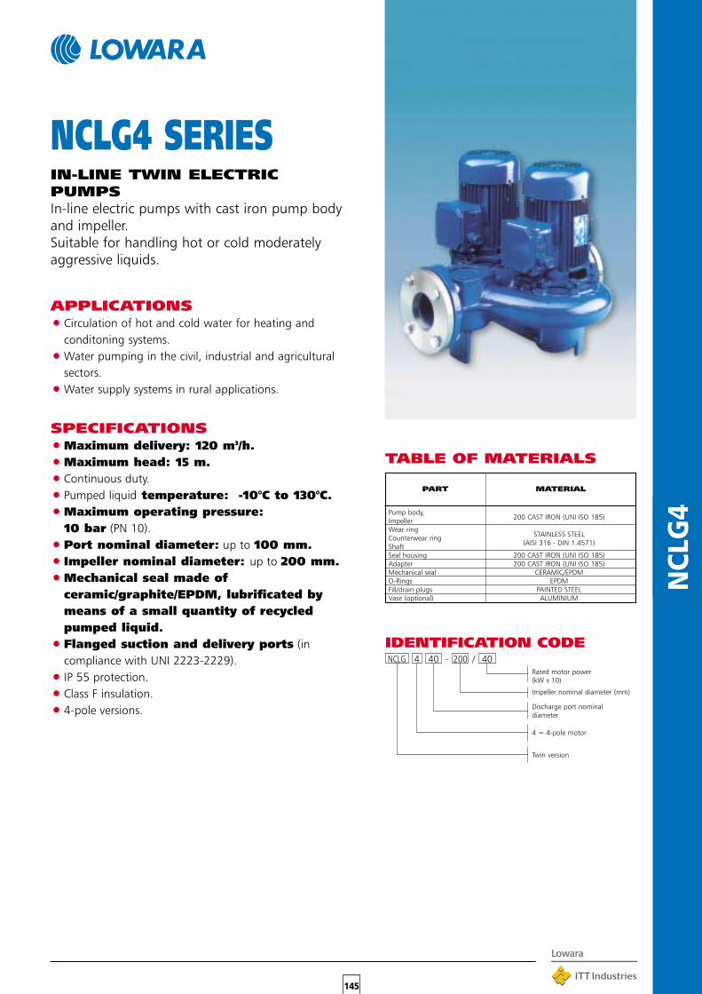
145
NCL
G4
TABLE OF MATERIALS
NCLG4 SERIESIN-LINE TWIN ELECTRICPUMPSIn-line electric pumps with cast iron pump bodyand impeller.Suitable for handling hot or cold moderatelyaggressive liquids.
APPLICATIONS•Circulation of hot and cold water for heating and
conditoning systems.
•Water pumping in the civil, industrial and agriculturalsectors.
•Water supply systems in rural applications.
SPECIFICATIONS•Maximum delivery: 120 m3/h.
•Maximum head: 15 m.
•Continuous duty.
•Pumped liquid temperature: -10°C to 130°C.
•Maximum operating pressure:10 bar (PN 10).
•Port nominal diameter: up to 100 mm.
• Impeller nominal diameter: up to 200 mm.
•Mechanical seal made ofceramic/graphite/EPDM, lubrificated bymeans of a small quantity of recycledpumped liquid.
•Flanged suction and delivery ports (incompliance with UNI 2223-2229).
•IP 55 protection.
•Class F insulation.
•4-pole versions.
PART MATERIAL
Pump body,200 CAST IRON (UNI ISO 185)Impeller
Wear ringSTAINLESS STEELCounterwear ring
(AISI 316 - DIN 1.4571)ShaftSeal housing 200 CAST IRON (UNI ISO 185)Adapter 200 CAST IRON (UNI ISO 185)Mechanical seal CERAMIC/EPDMO-Rings EPDMFill/drain plugs PAINTED STEELVase (optional) ALUMINIUM
NCLG 4 40 - 200 / 40
IDENTIFICATION CODE
Rated motor power(kW x 10)
Impeller nominal diameter (mm)
Discharge port nominaldiameter
4 = 4-pole motor
Twin version

146
NCL
G4
GENERAL VIEW OF THE PERFORMANCE CURVESAT 50 Hz NCLG4 SERIES (TWIN VERSION)

147
NCL
G4
40-125/02A 0,25 0,33 1,5 0,86 4,3 4 3,6 2,240-125/02 0,25 0,33 1,5 0,86 6,1 6 5,8 4,5 350-125/03 0,37 0,5 2,3 1,32 6,4 6,3 6,1 5,8 5,2 4,550-160/05 0,5 0,7 3,1 1,8 9 8,8 8,3 7,7 6,9 5,8 4,565-160/07 0,75 1 3,65 2,1 8,1 7,9 7,7 7,4 7 6 465-160/09 0,92 1,25 4,7 2,7 9 8,8 8,6 8,4 8 7 5,680-160/11 1,1 1,5 5 2,9 8,5 8,4 8,2 7,9 7,4 6,7 4,980-160/15 1,5 2 6,6 3,8 10,1 10 9,8 9,5 9,1 8,5 6,5100-200/30 3 4 12 7 12,211,811,510,8 10 9 8100-200/40 4 5,5 9 14,414,2 14 13,512,711,710,3 6,5
NCLG4 SERIESPERFORMANCE DATA AT 1450 rpm, 50 Hz
Data refer to the operation with only one pump working. To obtain the performances with both pumps working double the capacity for each head value.
Performances and powers stated are valid for a density ρ = 1,0 kg/dm3 and a maximum cinematic viscosity υ = 1 mm2/sec.
PUMP TYPE POWER RATEDCURRENT
A
kW HP ∆ Y ∆220-240 V 380-415 V 380-415 V
Q = DELIVERY
40 60 80 100 150 200 250 300 350 400 500 600 700 800 1000 1200 1400 1600 2000
2,4 3,6 4,8 6 9 12 15 18 21 24 30 36 42 48 60 72 84 96 120
H = TOTAL HEAD IN METRES OF COLUMN OF WATER
l/min
m3/h
DIMENSIONS NCLG4 SERIES
FLANGES
DN D K GHOLES
N° Ø
40 150 110 88 4 18
50 165 125 102 4 18
65 185 145 122 4 18
80 200 160 138 4 18
100 220 180 158 8 18
WELDED COUNTERFLANGES
PUMP TYPE
40-125/02A40-125/0250-125/0350-160/0565-160/0765-160/0980-160/1180-160/15100-200/30100-200/40
4040505065658080
100100
G 1”1/2 100 397 325 200 197 340 130 210 425 100 20 41G 1”1/2 100 397 325 200 197 340 130 210 425 100 20 41G 2” 110 427 325 217 210 365 145 220 435 105 22 46G 2” 110 480 325 245 235 410 170 240 435 120 22 52
G 1”1/2 130 543 345 275 268 450 180 270 475 140 22 65G 1”1/2 130 543 345 275 268 450 180 270 475 140 22 67G 3” 150 550 385 280 270 510 205 305 535 135 24 79G 3” 150 550 385 280 270 510 205 305 535 135 24 83G 4” 180 670 425 325 345 630 240 390 605 165 26 138G 4” 180 670 435 325 345 630 240 390 615 165 26 150
DIMENSIONS in mm
Ø D A B C E F H H1 H2 L M N
WEIGHT
kgDNADNM

148
SCUB
A*
SCUBA* SERIESCLOSE-COUPLEDSUBMERSIBLE PUMPS
APPLICATIONS•Water supply from rain water tanks or
reservoirs, 6” wells, basins and watercourses.•Sprinkler systems.•Pressure boosting with pump inserted directly
in tank or well, to avoid suction problems andnoise.
•Water display, fountains.
SPECIFICATIONS•Delivery: up to 7,5 m3/h.
•Head: up to 75,5 m.
•Maximum pump overall diameter: 128 mm.
•Maximum immersion depth: 20 m.
•Maximum permissible quantity of suspendedsand: 25 g/m3.
•Passage of solids up to 2.5 mm.
•Delivery port: Rp 11/4”.
•Rated motor power: 0.55 to 1.1 kW.
•Single-phase motor: 220-240 V, 50 Hz, built-inautomatic reset overload protection. A control box with2-pole switch and capacitor is available on request.
•Three-phase motor: 380-415 V, 50 Hz; overloadprotection to be provided by user and installed in thecontrol box (see control box section).
•Maximum supply voltage variations: ±5%
•Class F insulation.
•Can also operate in horizontal position.
•Maximum number of starts per hour, at regularintervals:25 for motors up to 0.9 kW.20 for motors 1.1 kW and up.
•Maximum temperature of water in contact with themotor: 40°C (continuous use).
CONSTRUCTIONFEATURES•Close-coupled, multiple-impeller submersible electric
pump.The liquid end is located under the motor, which iscooled by the pumped liquid.
PART MATERIAL
Outer sleeve,Upper support,Suction screen,
STAINLESS STEEL
Shaft,AISI 304 - DIN 1.4301
Screws and tie-rods, DiffusersImpeller NORYLUpper cap,
TECHNOPOLYMERMechanical seal housingLower bearing support DIE-CAST ALUMINIUMLower bearing SPECIAL RUBBERElastomers NITRILE RUBBER (NBR)Mechanical seal SILICON CARBIDE/
SILICON CARBIDE
TABLE OF MATERIALS
•Dry motorThe electric motor is protected by a doubleseal with an oil chamber.
•Sealing systemThe silicon carbide mechanical seal, highlyresistant to abrasion and wear, and the lipseal, continuously lubricated thanks to thespecial design of the oil chamber, ensure theabsolute tightness of the motor seal.In the event of dry running, the sealing systemwill not be damaged and the motor will notsuffer from infiltration.The oil used complies with FDA (FOOD ANDDRUG ADMINISTRATION) standards.
•Single-phase models with float (CG) are alsoavailable
All the nitrile rubber, polyurethane and polycarbonate components are suitablefor usage with foodstuffs and comply with FDA specification (the Food andDrug Administration is the US agency for the safeguard of public health).* Named SC for UK market.

149
SCUB
A*
SCUBA* SERIESOPERATING CHARACTERISTICS AT 2850 rpm 50 Hz
These performances are valid for liquids with density ρ = 1.0 kg/dm3 and kinematic viscosity γ = 1 mm2/sec.
* Named SC for UK market.

150
SCUB
A*
DIMENSIONS AND WEIGHTS
PUMP TYPE
DIMENSIONS
L WEIGHT
kgmm
2SC5
2SC7
2SC9
2SC11
4SC7
4SC9
4SC11
2SC5T
2SC7T
2SC9T
2SC11T
4SC7T
4SC9T
4SC11T
Disponibile versione monofase con galleggiante (SCUBA CG)
scuba-2p50_a_td
496
536
13.5
15
536
16
14.5
561
606
511
18
17.5
15
18
15.5
13.5
16
14.5
536
496
606
581
536
561
511
581
15.5
17.5
SCUBA* SERIESHYDRAULIC PERFORMANCE TABLE AT 2850 rpm
PUMP TYPE
l/min 0 20 30 40 50 60 75 80 100 125
m3/h 0 1.2 1.8 2.4 3 3.6 4.5 4.8 6 7.5
kW HP
RATED
POWER
Q = DELIVERY
H = TOTAL HEAD METERS COLUMN OF WATER
2SC5(T) 0.55 0.75 47.7 43.4 40.5 36.8 32.3 26.7 15.9
2SC7(T) 0.75 1 61.2 56.7 52.7 47.6 41.5 34.3 21.7
2SC9(T) 0.9 1.2 72.4 66.3 61.8 56.3 49.6 41.8 27.4
2SC11(T) 1.1 1.5 84.5 77.6 72.6 66.3 58.6 49.2 31.7
4SC7(T) 0.75 1 49.4 42.8 40.6 38.1 34.0 32.5 25.9 16.5
4SC9(T) 0.9 1.2 62.5 52.3 49.6 46.7 41.8 40.1 32.2 19.9
4SC11(T) 1.1 1.5 75.5 63.4 60.0 56.4 50.6 48.5 39.3 25.4
scuba-2p50_a_th
PUMP TYPE INPUT INPUT CAPACITOR PUMP TYPE
POWER* CURRENT*
220-240 V
A
220-240 V 380-415 V
kW µF / 450 V kW A A
220-240 V THREE-PHASE 220-240 V 380-415 V
kW A µF / 450 V kW A A
SINGLE-PHASE
INPUT
POWER*
INPUT
CURRENT*
INPUT
CURRENT*
2SC5 0.93 4.37 16 2SC5T 0.86 2.81 1.62
2SC7 1.15 5.19 25 2SC7T 1.09 4.12 2.38
2SC9 1.32 5.88 25 2SC9T 1.27 4.40 2.54
2SC11 1.63 7.25 30 2SC11T 1.45 4.68 2.70
4SC7 1.18 5.28 25 4SC7T 1.12 4.16 2.40
4SC9 1.38 6.17 25 4SC9T 1.33 4.50 2.60
4SC11 1.76 7.85 30 4SC11T 1.59 4.94 2.85
*Valori massimi nel campo di funzionamento scuba-2p50_a_te* Maximum value in specified range
Singlephase version with float switch available (SCUBA CG)

151
GS
GS SERIESSUBMERSIBLE PUMPSFOR 4” WELLS
APPLICATIONS•Water supply.•Sprinkler systems.•Pressure boosting.•Fire-fighting.•Fountains.
SPECIFICATIONS•Delivery up to 21 m3/h.
•Head up to 340 m.
•Maximum pump overall diameter (cable coverincluded): 99 mm.
•Maximum immersion depth: 150 m.
•Maximum permissible quantity of suspendedsand: 150 g/m3.
•1GSL - 2GS - 4GS - 6GS versions (radial impellers): 11/4”delivery port.
•8GS - 12GS - 16GS versions (semi-axial impellers): 2”delivery port.
•Rated motor power from 0.25 to 7.5 kW.
•Versions:Single-phase 220-230 V or 230-240 V, 50 Hz, from 0.25 to 2.2 kW.Three-phase 380-415 V, 50 Hz, from 0.37 to 7.5kW.- Overload protection to be provided by user andinstalled in the control box (see control box section).-Maximum supply voltage variations: +6%/-10%
•Maximum number of starts per hour, at regularintervals: 30 (4OS motor), 20 (F4 motor).
•Horizontal operation up to 2.2 kW with 4OS or F4 seriesmotors, with F4 motor for higher powers.
•Maximum temperature of water in contact with themotor: 30°C.
CONSTRUCTIONCHARACTERISTICSPUMP
•Abrasion resistant construction. The front wear plate,combined with the floating impellers, ensures optimumresistance to abrasion.
•The non-return valve is integrated in the head so as to
discharge the weight of the column of waterand any water hammer onto the head itself,thus safeguarding impellers and diffusers.
•The upper and lower supports are made ofprecision-cast stainless steel, ensuringresistance to corrosion, durability and a sturdycoupling to the motor.
•The GS series pumps can be coupled to either4OS or F4 motors.
MOTORFor 4OS motor characteristics, please see specificsection in this catalogue.
PART MATERIAL
Upper head,STAINLESS STEELValve cap,
(AISI 303 - DIN 1.4305)Valve seatValve gasket NITRILE RUBBERValve stop ring STAINLESS STEEL
(AISI 302 - DIN 1.4319)Upper support POLYCARBONATE/FIBERGLASSBearing POLYURETHANEDiffuser, impeller POLYCARBONATE/FIBERGLASSDiffuser case,Shim,Pump shaft,Outer sleeve, STAINLESS STEELSpacer, (AISI 304 - DIN 1.4301)Filter,Coupling,Cable cover
TABLE OF MATERIALS
All the nitrile rubber, polyurethane and polycarbonate components aresuitable for usage with foodstuffs and comply with FDA specification(the Food and Drug Administration is the US agency for the safeguard ofpublic health).

152
GS
1GSL, 2GS, 4GS, 6GS SERIESHYDRAULIC PERFORMANCE TABLE AT 2850 rpm, 50 Hz
1GSL02M 8 0,25 0,33 53 50 44,5 36,5 26,5 2,5 – 12,5 632 11,51GSL03M 12 0,37 0,5 79 75 66,5 55 40 3,5 – 16 722 131GSL03T 12 0,37 0,5 79 75 66,5 55 40 – 1,1 – 701 121GSL05M 18 0,55 0,75 119 112 100 83 60 4,5 – 20 854 15,51GSL05T 18 0,55 0,75 119 112 100 83 60 – 1,6 – 826 141GSL07M 24 0,75 1 159 150 133 110 80 5,7 – 30 981 17,51GSL07T 24 0,75 1 159 150 133 110 80 – 2,1 – 959 161GSL11M 35 1,1 1,5 232 218 194 160 116 8,2 – 40 1232 211GSL11T 35 1,1 1,5 232 218 194 160 116 – 3 – 1203 201GSL15M 49 1,5 2 324 305 272 224 163 10,5 – 50 1504 251GSL15T 49 1,5 2 324 305 272 224 163 – 4 – 1476 232GS02M 5 0,25 0,33 33 30 28 26 20 13 2,5 – 12,5 579 112GS03M 7 0,37 0,5 47 42 40 36 29 19 3,5 – 16 634 12,52GS03T 7 0,37 0,5 47 42 40 36 29 19 – 1,1 – 614 112GS05M 10 0,55 0,75 67 60 56 52 41 27 4,5 – 20 714 14,52GS05T 10 0,55 0,75 67 60 56 52 41 27 – 1,6 – 686 12,52GS07M 14 0,75 1 93 83 79 73 57 37 5,7 – 30 806 162GS07T 14 0,75 1 93 83 79 73 57 37 – 2,1 – 784 14,52GS11M 20 1,1 1,5 133 119 113 104 82 53 8,2 – 40 940 182GS11T 20 1,1 1,5 133 119 113 104 82 53 – 3 – 911 172GS15M 28 1,5 2 187 167 158 146 115 74 10,5 – 50 1138 212GS15T 28 1,5 2 187 167 158 146 115 74 – 4 – 1110 202GS22M 40 2,2 3 267 238 226 208 164 106 15,9 – 70 1452 282GS22T 40 2,2 3 267 238 226 208 164 106 – 5,9 – 1347 232GS30T 52 3 4 347 309 294 271 213 138 – 7,8 – 1623 314GS03M 4 0,37 0,5 27 24 23 21 19 13 3,5 – 16 598 124GS03T 4 0,37 0,5 27 24 23 21 19 13 – 1,1 – 578 10,54GS05M 7 0,55 0,75 47 42 40 37 33 22 15 4,5 – 20 691 144GS05T 7 0,55 0,75 47 42 40 37 33 22 15 – 1,6 – 663 124GS07M 9 0,75 1 60 54 51 47 42 28 19 5,7 – 30 756 15,54GS07T 9 0,75 1 60 54 51 47 42 28 19 – 2,1 – 734 144GS11M 14 1,1 1,5 94 84 80 74 66 44 30 8,2 – 40 893 17,54GS11T 14 1,1 1,5 94 84 80 74 66 44 30 – 3 – 864 164GS15M 19 1,5 2 127 114 108 100 89 60 40 10,5 – 50 1029 204GS15T 19 1,5 2 127 114 108 100 89 60 40 – 4 – 1001 18,54GS22M 27 2,2 3 181 162 154 142 127 85 57 15,9 – 70 1336 264GS22T 27 2,2 3 181 162 154 142 127 85 57 – 5,9 – 1231 224GS30T 35 3 4 228 204 194 179 160 107 72 – 7,8 – 1471 294GS40T 48 4 5,5 322 288 274 252 226 151 102 – 10 – 2065 356GS05M 5 0,55 0,75 30 26 25 22 21 17 12 4,5 – 20 710 14,56GS05T 5 0,55 0,75 30 26 25 22 21 17 12 – 1,6 – 682 12,56GS07M 7 0,75 1 43 36 35 31 29 24 16 5,7 – 30 794 166GS07T 7 0,75 1 43 36 35 31 29 24 16 – 2,1 – 772 14,56GS11M 10 1,1 1,5 61 52 49 44 41 34 23 8,2 – 40 916 186GS11T 10 1,1 1,5 61 52 49 44 41 34 23 – 3 – 887 16,56GS15M 14 1,5 2 85 72 69 62 58 48 32 10,5 – 50 1106 216GS15T 14 1,5 2 85 72 69 62 58 48 32 – 4 – 1078 19,56GS22M 21 2,2 3 128 108 104 93 87 71 48 15,9 – 70 1428 286GS22T 21 2,2 3 128 108 104 93 87 71 48 – 5,9 – 1323 236GS30T 29 3 4 177 150 143 128 120 99 67 – 7,8 – 1630 316GS40T 38 4 5,5 232 196 188 168 157 129 87 – 10 – 2223 376GS55T 52 5,5 7,5 317 268 257 230 215 177 120 – 13,7 – 2657 46
Performances in compliance with ISO 9906 – Annex A
Diameter of pump delivery port: 1GSL – 2GS – 4GS – 6GS: 11/4”.
PUMP NUMBERkW HP
Q = DELIVERY RATED CAPACI- ELECTRIC ELECTRICTYPE OF STAGES CURRENT TOR PUMP PUMP
LENGHT WEIGHTSINGLE- THREE-
H = TOTAL HEAD METERS COLUMN OF WATERPHASE PHASE220 V 380-415 V 450 V mm kg
l/min 0 5 10 15 20 25 30 40 50 60 80 90 110 133
m3/h 0 0,3 0,6 0,9 1,2 1,5 1,8 2,4 3 3,6 4,8 5,4 6,6 8

153
GS
8GS, 12GS, 16GS SERIESHYDRAULIC PERFORMANCE TABLE AT 2850 rpm, 50 Hz
Performances in compliance with ISO 9906 – Annex A
Diameter of pump delivery port: 8GS – 12GS – 16GS: 2”.
8GS07M 4 0,75 1 26 24 23 22 20 18 16 5,7 – 30 703 158GS07T 4 0,75 1 26 24 23 22 20 18 16 – 2,1 – 681 13,58GS11M 6 1,1 1,5 39 36 34 33 31 28 24 8,2 – 40 794 16,58GS11T 6 1,1 1,5 39 36 34 33 31 28 24 – 3 – 765 15,58GS15M 8 1,5 2 52 48 46 44 41 37 32 10,5 – 50 884 18,58GS15T 8 1,5 2 52 48 46 44 41 37 32 – 4 – 856 178GS22M 13 2,2 3 84 77 74 71 67 60 51 15,9 – 70 1144 258GS22T 13 2,2 3 84 77 74 71 67 60 51 – 5,9 – 1039 208GS30T 17 3 4 110 101 97 93 87 78 67 – 7,8 – 1268 288GS40T 23 4 5,5 149 137 132 126 118 106 91 – 10 – 1768 338GS55T 32 5,5 7,5 207 191 183 175 164 147 127 – 13,7 – 2039 408GS75T 43 7,5 10 279 256 246 235 220 198 170 – 19,8 – 2430 4712GS15M 7 1,5 2 43 37 35 33 30 25 17 10,5 – 50 1000 19,512GS15T 7 1,5 2 43 37 35 33 30 25 17 4 – 972 1812GS22M 10 2,2 3 61 53 50 47 43 36 24 15,9 – 70 1299 2612GS22T 10 2,2 3 61 53 50 47 43 36 24 – 5,9 – 1194 2112GS30T 14 3 4 86 74 70 66 61 50 34 – 7,8 – 1468 2912GS40T 19 4 5,5 116 100 95 89 83 68 46 – 10 – 1804 3512GS55T 26 5,5 7,5 159 137 130 122 113 94 63 – 13,7 – 2275 4312GS75T 35 7,5 10 215 184 175 164 152 126 85 – 19,8 – 2818 5216GS22M 8 2,2 3 47 37 36 32 27 23 16 15,9 – 70 1247 2616GS22T 8 2,2 3 47 37 36 32 27 23 16 – 5,9 – 1142 2116GS30T 11 3 4 65 51 49 44 38 31 22 – 7,8 – 1413 2916GS40T 15 4 5,5 89 70 67 60 51 43 30 – 10 – 1760 3516GS55T 20 5,5 7,5 118 94 89 80 69 57 41 – 13,7 – 2245 4316GS75T 28 7,5 10 165 131 125 112 96 80 57 – 19,8 – 2865 52
PUMP NUMBERkW HP
Q = DELIVERY RATED CAPACI- ELECTRIC ELECTRICTYPE OF
STAGESCURRENT TOR PUMP PUMP
LENGHT WEIGHT
SINGLE- THREE-
H = TOTAL HEAD METERS COLUMN OF WATER PHASE PHASE220 V 380-415 V 450 V mm kg
l/min 0 60 80 100 120 140 160 200 250 300 367
m3/h 0 3,6 4,8 6 7,2 8,4 9,6 12 15 18 22

154
GS
1GSL SERIESOPERATING CHARACTERISTICS AT 2850 rpm 50 Hz
These performances are valid for liquids with density ρ = 1.0 kg/dm3 and kinematic viscosity γ = 1 mm2/sec.
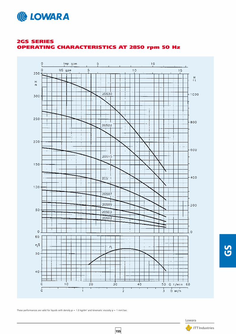
155
GS
2GS SERIESOPERATING CHARACTERISTICS AT 2850 rpm 50 Hz
These performances are valid for liquids with density ρ = 1.0 kg/dm3 and kinematic viscosity γ = 1 mm2/sec.

156
GS
4GS SERIESOPERATING CHARACTERISTICS AT 2850 rpm 50 Hz
These performances are valid for liquids with density ρ = 1.0 kg/dm3 and kinematic viscosity γ = 1 mm2/sec.

157
GS
6GS SERIESOPERATING CHARACTERISTICS AT 2850 rpm 50 Hz
These performances are valid for liquids with density ρ = 1.0 kg/dm3 and kinematic viscosity γ = 1 mm2/sec.

158
GS
8GS SERIESOPERATING CHARACTERISTICS AT 2850 rpm 50 Hz
These performances are valid for liquids with density ρ = 1.0 kg/dm3 and kinematic viscosity γ = 1 mm2/sec.

159
GS
12GS SERIESOPERATING CHARACTERISTICS AT 2850 rpm 50 Hz
These performances are valid for liquids with density ρ = 1.0 kg/dm3 and kinematic viscosity γ = 1 mm2/sec.

160
GS
16GS SERIESOPERATING CHARACTERISTICS AT 2850 rpm 50 Hz
These performances are valid for liquids with density ρ = 1.0 kg/dm3 and kinematic viscosity γ = 1 mm2/sec.

161
GS
1GSL02 8 298 Rp 1” 1/4 31GSL03 12 367 Rp 1” 1/4 41GSL05 18 472 Rp 1” 1/4 51GSL07 24 577 Rp 1” 1/4 61GSL11 35 799 Rp 1” 1/4 8,51GSL15 49 1043 Rp 1” 1/4 11,52GS02 5 245 Rp 1” 1/4 2,52GS03 7 280 Rp 1” 1/4 32GS05 10 332 Rp 1” 1/4 3,52GS07 14 402 Rp 1” 1/4 42GS11 20 507 Rp 1” 1/4 5,52GS15 28 677 Rp 1” 1/4 72GS22 40 886 Rp 1” 1/4 9,52GS30 52 1095 Rp 1” 1/4 124GS03 4 244 Rp 1” 1/4 2,54GS05 7 309 Rp 1” 1/4 34GS07 9 352 Rp 1” 1/4 3,54GS11 14 460 Rp 1” 1/4 4,54GS15 19 568 Rp 1” 1/4 5,54GS22 27 770 Rp 1” 1/4 7,54GS30 35 943 Rp 1” 1/4 94GS40 48 1223 Rp 1” 1/4 12,56GS05 5 328 Rp 1” 1/4 3,56GS07 7 390 Rp 1” 1/4 46GS11 10 483 Rp 1” 1/4 56GS15 14 645 Rp 1” 1/4 76GS22 21 862 Rp 1” 1/4 96GS30 29 1102 Rp 1” 1/4 11,56GS40 38 1381 Rp 1” 1/4 14,56GS55 52 1815 Rp 1” 1/4 198GS07 4 299 Rp 2” 38GS11 6 361 Rp 2” 48GS15 8 423 Rp 2” 4,58GS22 13 578 Rp 2” 68GS30 17 740 Rp 2” 88GS40 23 926 Rp 2” 9,58GS55 32 1197 Rp 2” 12,58GS75 43 1538 Rp 2” 16
12GS15 7 539 Rp 2” 512GS22 10 733 Rp 2” 7,512GS30 14 940 Rp 2” 9,512GS40 19 1200 Rp 2” 1212GS55 26 1556 Rp 2” 1612GS75 35 2023 Rp 2” 20,516GS22 8 681 Rp 2” 716GS30 11 885 Rp 2” 916GS40 15 1156 Rp 2” 11,516GS55 20 1526 Rp 2” 15,516GS75 28 2070 Rp 2” 21
DIMENSIONS AND WEIGHTS, GS SERIES
PUMP No. DIMENSION DNM WEIGHTTYPE STAGES L kg
NOTE: for motor dimensions and weights see pages dedicated to 4OS and F4 motors in this catalogue.
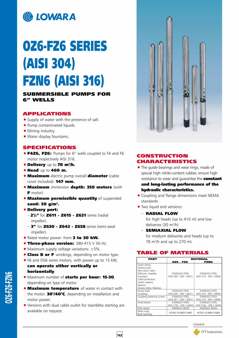
162
OZ6-F
Z6-FZN
6
CONSTRUCTIONCHARACTERISTICS•The guide bearings and wear rings, made of
special high nitrile-content rubber, ensure highresistance to wear and guarantee the constantand long-lasting performance of thehydraulic characteristics.
•Coupling and flange dimensions meet NEMAstandards.
•Two liquid end versions:
– RADIAL FLOWfor high heads (up to 410 m) and lowdeliveries (30 m3/h)
– SEMIAXIAL FLOWfor medium deliveries and heads (up to78 m3/h and up to 270 m).
OZ6-FZ6 SERIES(AISI 304)FZN6 (AISI 316)SUBMERSIBLE PUMPS FOR6” WELLS
APPLICATIONS•Supply of water with the presence of salt.
•Pump contaminated liquids.
•Mining industry.
•Water display fountains.
SPECIFICATIONS•F4Z6, FZ6: Pumps for 6” wells coupled to F4 and F6
motor respectively AISI 316.
•Delivery up to 78 m3/h.
•Head up to 460 m.
•Maximum electric pump overall diameter (cablecover included): 147 mm.
•Maximum immersion depth: 350 meters (withF motor)
•Maximum permissible quantity of suspendedsand: 50 g/m3.
•Delivery port:– 21/2” for Z611 - Z615 - Z621 series (radial
impeller).– 3” for Z630 - Z642 - Z658 series (semi-axial
impeller).
•Rated motor power: from 3 to 30 kW.
•Three-phase version: 380-415 V 50 Hz.
•Maximum supply voltage variations: ±5%.
•Class B or F windings, depending on motor type.
•F6 and OS6 series motors, with power up to 15 kW,can operate either vertically orhorizontally.
•Maximum number of starts per hour: 15-30,depending on type of motor.
•Maximum temperature of water in contact withthe motor: 30°/40°C, depending on installation andmotor power.
•Versions with dual cable outlet for star/delta starting areavailable on request.
TABLE OF MATERIALSPART MATERIAL
OZ6 - FZ6 FZN6Outer sleeve,Delivery port,Non-return valveDiffusers, Impeller, STAINLESS STEEL STAINLESS STEELConveyor, (AISI 304 - DIN 1.4301) (AISI 316 - DIN 1.4404)Cable protection,Lower support,Spacers,Screws, Bolts, WashersPump shaft, STAINLESS STEEL STAINLESS STEELCoupling (AISI 420 - DIN 1.4021) (AISI 316 - DIN 1.4404)Coupling fastening screws STAINLESS STEEL STAINLESS STEEL
(AISI 431 - DIN 1.4057) (AISI 316 - DIN 1.4404)Small blocks STAINLESS STEEL STAINLESS STEEL
(AISI 316L - DIN 1.4404) (AISI 316L - DIN 1.4404)Fifth wheel PHENOLIC RESIN PHENOLIC RESINWear rings,
NITRILE RUBBER (NBR) NITRILE RUBBER (NBR)Bush bearings
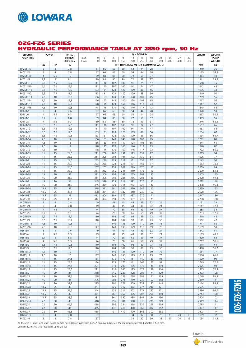
All the Z611 - Z621 and Z621 series pumps have delivery port with G 21/2” nominal diameter. The maximum external diameter is 147 mm.
Versions FZN6 AISI 316: available up to 22 kW
163
OZ6-F
Z6-FZN
6
ELECTRIC POWER RATED Q = DELIVERY LENGHT ELECTRIC PUMP TYPE CURRENT m3/h 0 3 6 9 12 15 18 21 24 27 30 PUMP
380-415 V l/min 0 50 100 150 200 250 300 350 400 450 500 WEIGHT
kW HP A H = TOTAL HEAD METERS COLUMN OF WATER mm kg
O4Z611/6 3 4 7,8 67 66 63 60 54 44 28 1210 35F4Z611/6 3 4 7,8 67 66 63 60 54 44 28 1195 34,8O4Z611/8 4 5,5 10 89 88 85 80 72 59 37 1364 40F4Z611/8 3,7 5 9,1 89 88 85 80 72 59 37 1311 39,5O4Z611/10 5,5 7,5 13,7 111 110 107 100 91 74 47 1558 46F4Z611/10 5,5 7,5 13,7 111 110 107 100 91 74 47 1542 48O4Z611/12 5,5 7,5 13,7 133 131 128 120 109 88 56 1635 48F4Z611/12 5,5 7,5 13,7 133 131 128 120 109 88 56 1619 50O4Z611/14 7,5 10 19,8 156 153 149 140 128 103 65 1789 55F4Z611/14 7,5 10 19,8 156 153 149 140 128 103 65 1767 56O4Z611/16 7,5 10 19,8 178 175 170 160 146 117 73 1867 57F4Z611/16 7,5 10 19,8 178 175 170 160 146 117 73 1845 58OZ611/6 3 4 7,6 67 66 63 60 54 44 28 1320 53FZ611/6 4 5,5 9,3 67 66 63 60 54 44 28 1267 50,5OZ611/8 3,7 5 8,8 89 88 85 80 72 59 37 1399 55FZ611/8 4 5,5 9,3 89 88 85 80 72 59 37 1346 52,5OZ611/10 5,5 7,5 12,5 111 110 107 100 91 74 47 1557 65FZ611/10 5,5 7,5 12,5 111 110 107 100 91 74 47 1457 58OZ611/12 5,5 7,5 12,5 133 131 128 120 109 88 56 1634 67FZ611/12 5,5 7,5 12,5 133 131 128 120 109 88 56 1534 59,7OZ611/14 7,5 10 17 156 153 149 140 128 103 65 1762 80FZ611/14 7,5 10 16 156 153 149 140 128 103 65 1644 65OZ611/16 7,5 10 17 178 175 170 160 146 117 73 1840 82FZ611/16 7,5 10 16 178 175 170 160 146 117 73 1722 66,5OZ611/19 11 15 24,5 211 208 202 191 173 139 87 2065 94FZ611/19 11 15 23,3 211 208 202 191 173 139 87 1905 77OZ611/21 11 15 24,5 233 230 223 211 191 153 97 2143 96FZ611/21 11 15 23,3 233 230 223 211 191 153 97 1983 78,8OZ611/24 11 15 24,5 267 262 255 241 219 175 110 2259 99FZ611/24 11 15 23,3 267 262 255 241 219 175 110 2099 81,8OZ611/28 15 20 31 311 306 298 281 255 204 130 2505 115FZ611/28 15 20 31,3 311 306 298 281 255 204 130 2320 92,3OZ611/31 15 20 31 345 339 329 311 282 226 142 2623 118FZ611/31 15 20 31,3 345 339 329 311 282 226 142 2438 95,3OZ611/34 18,5 25 39 378 371 361 342 310 249 157 2829 133FZ611/34 18,5 25 38,5 378 371 361 342 310 249 157 2620 105OZ611/37 18,5 25 39 412 404 393 372 337 270 171 2947 136FZ611/37 18,5 25 38,5 412 404 393 372 337 270 171 2738 108O4Z615/4 3 4 7,8 49 47 45 43 39 32 24 1131 33F4Z615/4 3 4 7,8 49 47 45 43 39 32 24 1117 32,8O4Z615/6 4 5,5 10 74 70 68 65 59 49 37 1285 38F4Z615/6 3,7 5 9,1 74 70 68 65 59 49 37 1233 37,5O4Z615/9 5,5 7,5 13,7 110 104 102 98 89 73 55 1518 45F4Z615/9 5,5 7,5 13,7 110 104 102 98 89 73 55 1502 47O4Z615/12 7,5 10 19,8 147 140 135 129 119 99 73 1711 52F4Z615/12 7,5 10 19,8 147 140 135 129 119 99 73 1689 53OZ615/4 3 4 7,6 49 47 45 43 39 32 24 1242 51FZ615/4 4 5,5 9,3 49 47 45 43 39 32 24 1189 48,5OZ615/6 3,7 5 8,8 74 70 68 65 59 49 37 1320 53FZ615/6 4 5,5 9,3 74 70 68 65 59 49 37 1267 50,5OZ615/9 5,5 7,5 12,5 110 104 102 98 89 73 55 1518 64FZ615/9 5,5 7,5 12,5 110 104 102 98 89 73 55 1418 56,7OZ615/12 7,5 10 17 147 140 135 129 119 99 73 1684 77FZ615/12 7,5 10 16 147 140 135 129 119 99 73 1566 61,5OZ615/15 11 15 24,5 184 175 170 161 149 123 91 1909 90FZ615/15 11 15 23,3 184 175 170 161 149 123 91 1749 72,8OZ615/18 11 15 24,5 221 210 203 195 178 148 110 2025 93FZ615/18 11 15 23,3 221 210 203 195 178 148 110 1865 75,8OZ615/21 15 20 31 258 245 238 228 208 171 129 2233 108FZ615/21 15 20 31,3 258 245 238 228 208 171 129 2048 85,3OZ615/24 15 20 31 295 280 271 259 238 197 148 2349 111FZ615/24 15 20 31,3 295 280 271 259 238 197 148 2164 88,3OZ615/28 18,5 25 39 344 326 317 302 277 230 171 2595 127FZ615/28 18,5 25 38,5 344 326 317 302 277 230 171 2386 98,7OZ615/31 18,5 25 39 381 361 350 335 307 254 190 2713 130FZ615/31 18,5 25 38,5 381 361 350 335 307 254 190 2504 102OZ615/34 22 30 46 418 396 384 368 336 279 209 2919 144FZ615/34 22 30 45,3 418 396 384 368 336 279 209 2685 111OZ615/37 22 30 46 455 431 419 400 366 302 252 3037 147FZ615/37 22 30 45,3 455 431 419 400 366 302 252 2803 114O4Z621/3 3 4 7,8 37 34 32 30 28 23 20 13 1109 32F4Z621/3 3 4 7,8 37 34 32 30 28 23 20 13 1094 31,8
OZ6-FZ6 SERIESHYDRAULIC PERFORMANCE TABLE AT 2850 rpm, 50 Hz
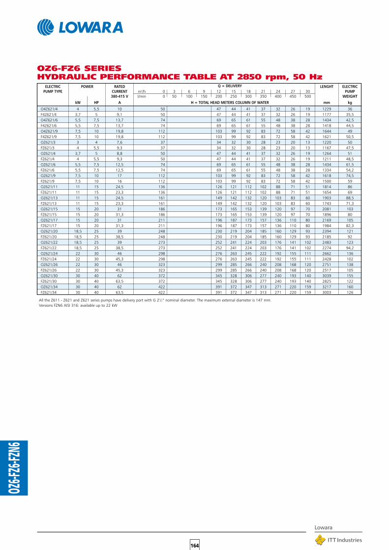
All the Z611 - Z621 and Z621 series pumps have delivery port with G 21/2” nominal diameter. The maximum external diameter is 147 mm.Versions FZN6 AISI 316: available up to 22 kW
164
OZ6-F
Z6-FZN
6
ELECTRIC POWER RATED Q = DELIVERY LENGHT ELECTRIC PUMP TYPE CURRENT m3/h 0 3 6 9 12 15 18 21 24 27 30 PUMP
380-415 V l/min 0 50 100 150 200 250 300 350 400 450 500 WEIGHT
kW HP A H = TOTAL HEAD METERS COLUMN OF WATER mm kg
O4Z621/4 4 5,5 10 50 47 44 41 37 32 26 19 1229 36F4Z621/4 3,7 5 9,1 50 47 44 41 37 32 26 19 1177 35,5O4Z621/6 5,5 7,5 13,7 74 69 65 61 55 48 38 28 1434 42,5F4Z621/6 5,5 7,5 13,7 74 69 65 61 55 48 38 28 1418 44,5O4Z621/9 7,5 10 19,8 112 103 99 92 83 72 58 42 1644 49F4Z621/9 7,5 10 19,8 112 103 99 92 83 72 58 42 1621 50,5OZ621/3 3 4 7,6 37 34 32 30 28 23 20 13 1220 50FZ621/3 4 5,5 9,3 37 34 32 30 28 23 20 13 1167 47,5OZ621/4 3,7 5 8,8 50 47 44 41 37 32 26 19 1264 51FZ621/4 4 5,5 9,3 50 47 44 41 37 32 26 19 1211 48,5OZ621/6 5,5 7,5 12,5 74 69 65 61 55 48 38 28 1434 61,5FZ621/6 5,5 7,5 12,5 74 69 65 61 55 48 38 28 1334 54,2OZ621/9 7,5 10 17 112 103 99 92 83 72 58 42 1618 74,5FZ621/9 7,5 10 16 112 103 99 92 83 72 58 42 1500 59OZ621/11 11 15 24,5 136 126 121 112 102 88 71 51 1814 86FZ621/11 11 15 23,3 136 126 121 112 102 88 71 51 1654 69OZ621/13 11 15 24,5 161 149 142 132 120 103 83 60 1903 88,5FZ621/13 11 15 23,3 161 149 142 132 120 103 83 60 1743 71,3OZ621/15 15 20 31 186 173 165 153 139 120 97 70 2081 103FZ621/15 15 20 31,3 186 173 165 153 139 120 97 70 1896 80OZ621/17 15 20 31 211 196 187 173 157 136 110 80 2169 105FZ621/17 15 20 31,3 211 196 187 173 157 136 110 80 1984 82,3OZ621/20 18,5 25 39 248 230 219 204 185 160 129 93 2394 121FZ621/20 18,5 25 38,5 248 230 219 204 185 160 129 93 2185 92OZ621/22 18,5 25 39 273 252 241 224 203 176 141 102 2483 123FZ621/22 18,5 25 38,5 273 252 241 224 203 176 141 102 2274 94,2OZ621/24 22 30 46 298 276 263 245 222 192 155 111 2662 136FZ621/24 22 30 45,3 298 276 263 245 222 192 155 111 2428 102OZ621/26 22 30 46 323 299 285 266 240 208 168 120 2751 138FZ621/26 22 30 45,3 323 299 285 266 240 208 168 120 2517 105OZ621/30 30 40 62 372 345 328 306 277 240 193 140 3039 155FZ621/30 30 40 63,5 372 345 328 306 277 240 193 140 2825 122OZ621/34 30 40 62 422 391 372 347 313 271 220 159 3217 160FZ621/34 30 40 63,5 422 391 372 347 313 271 220 159 3003 126
OZ6-FZ6 SERIESHYDRAULIC PERFORMANCE TABLE AT 2850 rpm, 50 Hz

All the Z630 - Z642 and Z658 series pumps have delivery port with G 3” nominal diameter. The maximum external diameter is 147 mm.Versions FZN6 AISI 316: available up to 22 kW
165
OZ6-F
Z6-FZN
6
OZ6-FZ6 SERIESHYDRAULIC PERFORMANCE TABLE AT 2850 rpm, 50 Hz
ELECTRIC POWER RATED Q = DELIVERY LENGHT ELECTRICPUMP TYPE CURRENT m3/h 0 6 12 18 24 30 36 42 48 54 60 66 72 78 PUMP
380-415 V l/min 0 100 200 300 400 500 600 700 800 900 1000 1100 1200 1300 WEIGHT
kW HP A H = TOTAL HEAD METERS COLUMN OF WATER mm kg
O4Z630/2 3 4 7,8 30 29 27 23 21 20 16 10 1226 33F4Z630/2 3 4 7,8 30 29 27 23 21 20 16 10 1211 33,5O4Z630/3 4 5,5 10 45 43 40 36 33 29 24 15 1414 39F4Z630/3 3,7 5 9,1 45 43 40 36 33 29 24 15 1361 38,5O4Z630/4 5,5 7,5 13,7 60 58 53 48 44 39 31 20 1641 45,5F4Z630/4 5,5 7,5 13,7 60 58 53 48 44 39 31 20 1625 47,5O4Z630/6 7,5 10 19,8 91 87 79 72 66 58 48 30 1941 54F4Z630/6 7,5 10 19,8 91 87 79 72 66 58 48 30 1919 55,5OZ630/2 3 4 7,6 30 29 27 23 21 20 16 10 1337 51,5FZ630/2 4 5,5 9,3 30 29 27 23 21 20 16 10 1284 49OZ630/3 3,7 5 8,8 45 43 40 36 33 29 24 15 1449 54FZ630/3 4 5,5 9,3 45 43 40 36 33 29 24 15 1396 51,5OZ630/4 5,5 7,5 12,5 60 58 53 48 44 39 31 20 1641 64,5FZ630/4 5,5 7,5 12,5 60 58 53 48 44 39 31 20 1541 57OZ630/6 7,5 10 17 91 87 79 72 66 58 48 30 1915 79,5FZ630/6 7,5 10 16 91 87 79 72 66 58 48 30 1797 64OZ630/9 11 15 24,5 137 130 118 108 99 87 71 43 2358 97FZ630/9 11 15 23,3 137 130 118 108 99 87 71 43 2198 80OZ630/12 15 20 31 183 174 158 144 132 117 95 59 2784 117FZ630/12 15 20 31,3 183 174 158 144 132 117 95 59 2599 94OZ630/15 18,5 25 39 228 217 198 180 165 146 119 73 3210 136FZ630/15 18,5 25 38,5 228 217 198 180 165 146 119 73 3001 108OZ630/18 22 30 46 274 260 237 216 198 174 142 88 3636 155FZ630/18 22 30 45,3 274 260 237 216 198 174 142 88 3402 121OZ630/21 30 40 62 320 304 276 252 230 204 167 102 4082 175FZ630/21 30 40 63,5 320 304 276 252 230 204 167 102 3868 142OZ630/24 30 40 62 365 348 315 288 263 233 190 118 4418 183FZ630/24 30 40 63,5 365 348 315 288 263 233 190 118 4204 149O4Z642/2 4 5,5 10 30 23 21 19 18 15 12 9 1302 36F4Z642/2 3,7 5 9,1 30 23 21 19 18 15 12 9 1249 36O4Z642/3 5,5 7,5 13,7 45 34 31 29 26 22 18 13 1529 43F4Z642/3 5,5 7,5 13,7 45 34 31 29 26 22 18 13 1513 4504Z642/5 7,5 10 19,8 75 57 53 49 43 38 30 23 1829 52F4Z642/5 7,5 10 19,8 75 57 53 49 43 38 30 23 1807 53OZ642/2 3,7 5 8,8 30 23 21 19 18 15 12 9 1337 51,5FZ642/2 4 5,5 9,3 30 23 21 19 18 15 12 9 1284 49OZ642/3 5,5 7,5 12,5 45 34 31 29 26 22 18 13 1529 62FZ642/3 5,5 7,5 12,5 45 34 31 29 26 22 18 13 1429 54,7OZ642/5 7,5 10 17 75 57 53 49 43 38 30 23 1803 77FZ642/5 7,5 10 16 75 57 53 49 43 38 30 23 1685 61,5OZ642/7 11 15 24,5 105 80 74 68 60 52 43 32 2134 91FZ642/7 11 15 23,3 105 80 74 68 60 52 43 32 1974 73,8OZ642/9 15 20 31 135 103 96 87 78 67 55 41 2448 109FZ642/9 15 20 31,3 135 103 96 87 78 67 55 41 2263 86,3OZ642/10 15 20 31 151 114 106 97 86 75 60 47 2560 112FZ642/10 15 20 31,3 151 114 106 97 86 75 60 47 2375 88,8OZ642/12 18,5 25 39 181 137 127 116 103 90 74 55 2874 129FZ642/12 18,5 25 38,5 181 137 127 116 103 90 74 55 2665 100OZ642/15 22 30 46 226 171 159 145 130 111 92 70 3300 147FZ642/15 22 30 45,3 226 171 159 145 130 111 92 70 3066 114OZ642/17 30 40 62 257 194 180 164 148 128 103 79 3634 165FZ642/17 30 40 63,5 257 194 180 164 148 128 103 79 3420 132OZ642/19 30 40 62 287 217 201 184 165 142 117 89 3858 170FZ642/19 30 40 63,5 287 217 201 184 165 142 117 89 3644 137FZ642/22 37 50 73 332 251 233 213 191 164 135 103 4358 180FZ642/24 37 50 73 362 274 254 232 208 179 148 112 4582 185O4Z658/2 4 5,5 10 27 20 18 17 16 15 14 12 9 1302 36F4Z658/2 3,7 5 9,1 27 20 18 17 16 15 14 12 9 1249 36O4Z658/3 5,5 7,5 13,7 42 30 28 26 25 23 20 17 14 1529 43F4Z658/3 5,5 7,5 13,7 42 30 28 26 25 23 20 17 14 1513 45O4Z658/4 7,5 10 19,8 55 40 37 35 33 30 27 23 19 1717 49F4Z658/4 7,5 10 19,8 55 40 37 35 33 30 27 23 19 1695 50,5OZ658/2 3,7 5 8,8 27 20 18 17 16 15 14 12 9 1337 51,5FZ658/2 4 5,5 9,3 27 20 18 17 16 15 14 12 9 1284 49OZ658/3 5,5 7,5 12,5 42 30 28 26 25 23 20 17 14 1529 62FZ658/3 5,5 7,5 12,5 42 30 28 26 25 23 20 17 14 1429 54,7OZ658/4 7,5 10 17 55 40 37 35 33 30 27 23 19 1691 74,5FZ658/4 7,5 10 16 55 40 37 35 33 30 27 23 19 1573 59OZ658/6 11 15 24,5 83 60 56 52 49 46 41 35 28 2022 88,5FZ658/6 11 15 23,3 83 60 56 52 49 46 41 35 28 1862 71,3OZ658/8 15 20 31 110 80 74 70 66 61 54 47 37 2336 107FZ658/8 15 20 31,3 110 80 74 70 66 61 54 47 37 2151 84OZ658/10 18,5 25 39 138 100 93 87 82 76 68 59 47 2650 124FZ658/10 18,5 25 38,5 138 100 93 87 82 76 68 59 47 2441 96OZ658/12 22 30 46 165 120 111 104 98 91 81 70 57 2964 140FZ658/12 22 30 45,3 165 120 111 104 98 91 81 70 57 2730 107OZ658/14 30 40 62 193 140 130 122 114 106 95 82 66 3298 158FZ658/14 30 40 63,5 193 140 130 122 114 106 95 82 66 3084 124OZ658/16 30 40 62 221 160 148 139 131 121 109 94 76 3522 163FZ658/16 30 40 63,5 221 160 148 139 131 121 109 94 76 3308 129FZ658/19 37 50 73 262 190 176 165 156 144 129 112 90 4022 172

166
OZ6-F
Z6-FZN
6
Z611 SERIESOPERATING CHARACTERISTICS AT 2850 rpm, 50 Hz
These performances are valid for liquids with density ρ = 1.0 kg/dm3 and kinematic viscosity γ = 1 mm2/sec.Versions FZN6 AISI 316: available up to 22 kW
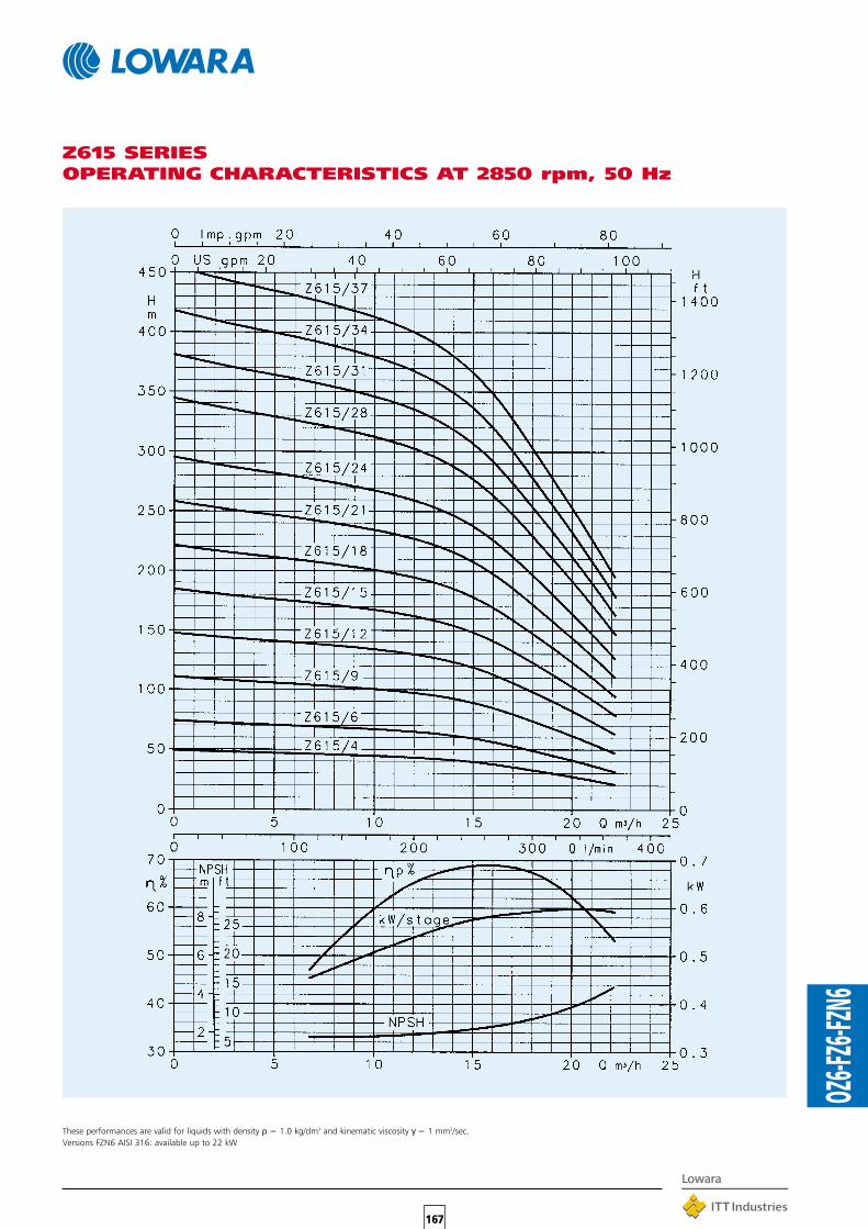
167
OZ6-F
Z6-FZN
6
Z615 SERIESOPERATING CHARACTERISTICS AT 2850 rpm, 50 Hz
These performances are valid for liquids with density ρ = 1.0 kg/dm3 and kinematic viscosity γ = 1 mm2/sec.Versions FZN6 AISI 316: available up to 22 kW

168
OZ6-F
Z6-FZN
6
Z621 SERIESOPERATING CHARACTERISTICS AT 2850 rpm, 50 Hz
These performances are valid for liquids with density ρ = 1.0 kg/dm3 and kinematic viscosity γ = 1 mm2/sec.Versions FZN6 AISI 316: available up to 22 kW

169
OZ6-F
Z6-FZN
6
Z630 SERIESOPERATING CHARACTERISTICS AT 2850 rpm, 50 Hz
These performances are valid for liquids with density ρ = 1.0 kg/dm3 and kinematic viscosity γ = 1 mm2/sec.Versions FZN6 AISI 316: available up to 22 kW
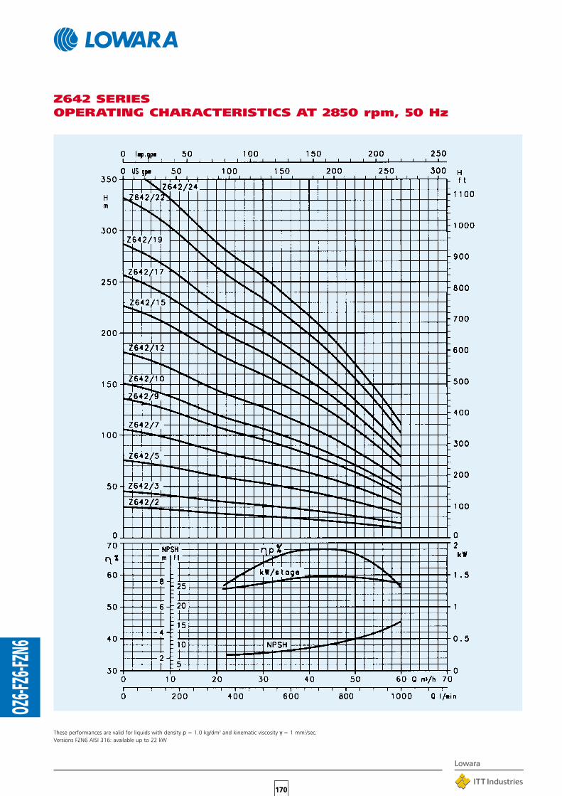
170
OZ6-F
Z6-FZN
6
Z642 SERIESOPERATING CHARACTERISTICS AT 2850 rpm, 50 Hz
These performances are valid for liquids with density ρ = 1.0 kg/dm3 and kinematic viscosity γ = 1 mm2/sec.Versions FZN6 AISI 316: available up to 22 kW

171
OZ6-F
Z6-FZN
6
Z658 SERIESOPERATING CHARACTERISTICS AT 2850 rpm, 50 Hz
These performances are valid for liquids with density ρ = 1.0 kg/dm3 and kinematic viscosity γ = 1 mm2/sec.Versions FZN6 AISI 316: available up to 22 kW

172
OZ6-F
Z6-FZN
6
505161748688103105121123136138155160
535565678082949699115118133136
354046485557
47485459697180829294102105122126
5052586065667778829295105108
ø138,5 G 21⁄2”ø138,5 G 21⁄2”ø138,5 G 21⁄2”ø138,5 G 21⁄2”ø138,5 G 21⁄2”ø138,5 G 21⁄2”
F4Z615/4 1117F4Z615/6 1233F4Z615/9 1502F4Z615/12 1689
F4Z611/6 1195F4Z611/8 1311F4Z611/10 1542F4Z611/12 1619F4Z611/14 1767F4Z611/16 1845
DIMENSIONS AND WEIGHTS
OVERALLPUMP DIMENSIONS DNM WEIGHTTYPE IN mm kg
A D
FZ
354048505657
ø138,5 G 21⁄2”ø138,5 G 21⁄2”ø138,5 G 21⁄2”ø138,5 G 21⁄2”
33384753
F4Z621/3 1094F4Z621/4 1177F4Z621/6 1418F4Z621/9 1621
ø138,5 G 21⁄2”ø138,5 G 21⁄2”ø138,5 G 21⁄2”ø138,5 G 21⁄2”
32364451
F4Z630/2 1211F4Z630/3 1361F4Z630/4 1625F4Z630/6 1919
ø138,5 G 3”ø138,5 G 3”ø138,5 G 3”ø138,5 G 3”
33384755
F4Z642/2 1249F4Z642/3 1513F4Z642/5 1807
ø138,5 G 3”ø138,5 G 3”ø138,5 G 3”
364553
F4Z658/2 1249F4Z658/3 1513F4Z658/4 1695
ø138,5 G 3”ø138,5 G 3”ø138,5 G 3”
364550
FZ611/6 1267FZ611/8 1346FZ611/10 1457FZ611/12 1534FZ611/14 1644FZ611/16 1722FZ611/19 1905FZ611/21 1983FZ611/24 2099FZ611/28 2320FZ611/31 2438FZ611/34 2620FZ611/37 2738
ø144 G 21⁄2”ø144 G 21⁄2”ø144 G 21⁄2”ø144 G 21⁄2”ø144 G 21⁄2”ø144 G 21⁄2”ø144 G 21⁄2”ø144 G 21⁄2”ø144 G 21⁄2”ø144 G 21⁄2”ø144 G 21⁄2”ø144 G 21⁄2”ø144 G 21⁄2”
FZ615/4 1189FZ615/6 1267FZ615/9 1418FZ615/12 1566FZ615/15 1749FZ615/18 1865FZ615/21 2048FZ615/24 2164FZ615/28 2386FZ615/31 2504FZ615/34 2685FZ615/37 2803
ø144 G 21⁄2”ø144 G 21⁄2”ø144 G 21⁄2”ø144 G 21⁄2”ø144 G 21⁄2”ø144 G 21⁄2”ø144 G 21⁄2”ø144 G 21⁄2”ø144 G 21⁄2”ø144 G 21⁄2”ø144 G 21⁄2”ø144 G 21⁄2”
485057627376858899102111114
FZ621/3 1167FZ621/4 1211FZ621/6 1334FZ621/9 1500FZ621/11 1654FZ621/13 1743FZ621/15 1896FZ621/17 1984FZ621/20 2185FZ621/22 2274FZ621/24 2428FZ621/26 2517FZ621/30 2825FZ621/34 3003
ø144 G 21⁄2”ø144 G 21⁄2”ø144 G 21⁄2”ø144 G 21⁄2”ø144 G 21⁄2”ø144 G 21⁄2”ø144 G 21⁄2”ø144 G 21⁄2”ø144 G 21⁄2”ø144 G 21⁄2”ø144 G 21⁄2”ø144 G 21⁄2”ø144 G 21⁄2”ø144 G 21⁄2”
FZ630/2 1284FZ630/3 1396FZ630/4 1541FZ630/6 1797FZ630/9 2198FZ630/12 2599FZ630/15 3001FZ630/18 3402FZ630/21 3868FZ630/24 4204
ø144 G 3”ø144 G 3”ø144 G 3”ø144 G 3”ø144 G 3”ø144 G 3”ø144 G 3”ø144 G 3”ø144 G 3”ø144 G 3”
495157648094108121142149
OVERALLPUMP DIMENSIONS DNM WEIGHTTYPE IN mm kg
A D
OZ
O4Z611/6 1210O4Z611/8 1364O4Z611/10 1558O4Z611/12 1635O4Z611/14 1789O4Z611/16 1867
ø138,5 G 21⁄2”ø138,5 G 21⁄2”ø138,5 G 21⁄2”ø138,5 G 21⁄2”ø138,5 G 21⁄2”ø138,5 G 21⁄2”
O4Z615/4 1131O4Z615/6 1285O4Z615/9 1518O4Z615/12 1711
ø138,5 G 21⁄2”ø138,5 G 21⁄2”ø138,5 G 21⁄2”ø138,5 G 21⁄2”
33384552
O4Z621/3 1109O4Z621/4 1229O4Z621/6 1434O4Z621/9 1644
ø138,5 G 21⁄2”ø138,5 G 21⁄2”ø138,5 G 21⁄2”ø138,5 G 21⁄2”
32364249
O4Z630/2 1226O4Z630/3 1414O4Z630/4 1641O4Z630/6 1941
ø138,5 G 3”ø138,5 G 3”ø138,5 G 3”ø138,5 G 3”
33394554
O4Z642/2 1302O4Z642/3 1529O4Z642/5 1829
ø138,5 G 3”ø138,5 G 3”ø138,5 G 3”
364352
O4Z658/2 1302O4Z658/3 1529O4Z658/4 1717
ø138,5 G 3”ø138,5 G 3”ø138,5 G 3”
364349
OZ611/6 1320OZ611/8 1399OZ611/10 1557OZ611/12 1634OZ611/14 1762OZ611/16 1840OZ611/19 2065OZ611/21 2143OZ611/24 2259OZ611/28 2505OZ611/31 2623OZ611/34 2829OZ611//37 2947
ø147 G 21⁄2”ø147 G 21⁄2”ø147 G 21⁄2”ø147 G 21⁄2”ø147 G 21⁄2”ø147 G 21⁄2”ø147 G 21⁄2”ø147 G 21⁄2”ø147 G 21⁄2”ø147 G 21⁄2”ø147 G 21⁄2”ø147 G 21⁄2”ø147 G 21⁄2”
OZ615/4 1242OZ615/6 1320OZ615/9 1518OZ615/12 1684OZ615/15 1909OZ615/18 2025OZ615/21 2233OZ615/24 2349OZ615/28 2595OZ615/31 2713OZ615/34 2919OZ615/37 3037
ø147 G 21⁄2”ø147 G 21⁄2”ø147 G 21⁄2”ø147 G 21⁄2”ø147 G 21⁄2”ø147 G 21⁄2”ø147 G 21⁄2”ø147 G 21⁄2”ø147 G 21⁄2”ø147 G 21⁄2”ø147 G 21⁄2”ø147 G 21⁄2”
515364779093108111127130144147
OZ621/3 1220OZ621/4 1264OZ621/6 1434OZ621/9 1618OZ621/11 1814OZ621/13 1903OZ621/15 2081OZ621/17 2169OZ621/20 2394OZ621/22 2483OZ621/24 2662OZ621/26 2751OZ621/30 3039OZ621/34 3217
ø147 G 21⁄2”ø147 G 21⁄2”ø147 G 21⁄2”ø147 G 21⁄2”ø147 G 21⁄2”ø147 G 21⁄2”ø147 G 21⁄2”ø147 G 21⁄2”ø147 G 21⁄2”ø147 G 21⁄2”ø147 G 21⁄2”ø147 G 21⁄2”ø147 G 21⁄2”ø147 G 21⁄2”
OZ630/2 1337OZ630/3 1449OZ630/4 1641OZ630/6 1915OZ630/9 2358OZ630/12 2784OZ630/15 3210OZ630/18 3636OZ630/21 4082OZ630/24 4418
ø147 G 3”ø147 G 3”ø147 G 3”ø147 G 3”ø147 G 3”ø147 G 3”ø147 G 3”ø147 G 3”ø147 G 3”ø147 G 3”
5154647997117136155175183

173
OZ6-F
Z6-FZN
6
OZ642/2 1337OZ642/3 1529OZ642/5 1803OZ642/7 2134OZ642/9 2448OZ642/10 2560OZ642/12 2874OZ642/15 3300OZ642/17 3634OZ642/19 3858
51627791109112129147165170
495559718496107124129172
OVERALLPUMP DIMENSIONS DNM WEIGHTTYPE IN mm kg
A D495562748689100114132137180180
DIMENSIONS AND WEIGHTS
FZ
FZ642/2 1284FZ642/3 1429FZ642/5 1685FZ642/7 1974FZ642/9 2263FZ642/10 2375FZ642/12 2665FZ642/15 3066FZ642/17 3420FZ642/19 3644FZ642/22 4358FZ642/24 4582
ø144 G 3”ø144 G 3”ø144 G 3”ø144 G 3”ø144 G 3”ø144 G 3”ø144 G 3”ø144 G 3”ø144 G 3”ø144 G 3”ø144 G 3”ø144 G 3”
FZ658/2 1284FZ658/3 1429FZ658/4 1573FZ658/6 1862FZ658/8 2151FZ658/10 2441FZ658/12 2730FZ658/14 3084FZ658/16 3308FZ658/19 4022
ø144 G 3”ø144 G 3”ø144 G 3”ø144 G 3”ø144 G 3”ø144 G 3”ø144 G 3”ø144 G 3”ø144 G 3”ø144 G 3”
OVERALLPUMP DIMENSIONS DNM WEIGHTTYPE IN mm kg
A D
OZ
ø147 G 3”ø147 G 3”ø147 G 3”ø147 G 3”ø147 G 3”ø147 G 3”ø147 G 3”ø147 G 3”ø147 G 3”ø147 G 3”
OZ658/2 1337OZ658/3 1529OZ658/4 1691OZ658/6 2022OZ658/8 2336OZ658/10 2650OZ658/12 2964OZ658/14 3298OZ658/16 3522
ø147 G 3”ø147 G 3”ø147 G 3”ø147 G 3”ø147 G 3”ø147 G 3”ø147 G 3”ø147 G 3”ø147 G 3”
51627488107124140158163

1744OS-
OS6
4OS-OS6 SERIESWITH REMOVABLE CONNECTORSubmersible motors in cooling filling fluidsuitable for use with foodstuffs.The choice of component materials ensuresoptimum operating performances, superiorquality, reliability and ease of installation.❏ REWINDABLE STATOR❏ ENVIRONMENTAL FRIENDLY COOLING
FLUID (F.D.A. APPROVED)❏ HIGH STARTING TORQUE❏ ELECTRIC CABLE WITH REMOVAL
CONNECTOR AVAILABLE FOR BOTH4OS-OS6.(THIS ALLOWS TO CHANGE THEDAMAGED CABLE AT SITE OR USE THESAME CABLE IF CHANGING THE MOTORALONE).
SPECIFICATIONS•Shaft extension and couplings in compliance with
NEMA standards.
•Rewindable stator.
•Winding insulation: class B (4OS)class F (OS6).
•Protection grade: IP58.
•Filling fluid in compliance with standards concerningoils in contact with foodstuffs and with the purityrequirements specified by the annex to G.U. no. 104 of20/04/1973; it also complies with F.D.A. (FOOD ANDDRUG ADMINISTRATION) standards.
•Large compensation bellows provide for theexpansion of the internal liquid.
•Shaft supported by angular bearings.
•Mechanical seal with sand protection.
•Maximum immersion depth: 150 m (OS6).
•Maximum number of starts per hour, at regularintervals:4OS: 30 for direct start;OS6: 15 for direct start;
20 for impedance start.
•Maximum allowable voltage fluctuations over the ratedvoltage: -10% / +6% 50 Hz
±10% 60 Hz.
•Models:– Single-phase 4OS:
from 0,25 to 2,2 kW 220-230 V, 230-240 V, 50 Hzfrom 0,37 to 2,2 kW 220-230 V, 60 Hzfrom 0,37 to 1,1 kW 110-115 V, 0,5 Hz
– Three-phase 4OS:from 0,37 to 5,5 kW 220-240 V, 50 Hzfrom 0,37 to 7,5 kW 380-415 V, 50 Hzfrom 0,37 to 7,5 kW 380 V, 60 Hzfrom 0,37 to 5,5 kW 220-230 V, 60 Hz
– Three-phase OS6:from 3 to 30 kW 380-415 V, 50 Hzfrom 3,7 to 15 kW 220-230 V, 60 Hzfrom 3,7 to 30 kW 380 V, 60 Hz
Different voltages on request.•OS6 motor version with dual cable outlet for
star-delta starting is available on request, with220-240 V for powers up to 15 kW (20 HP)and with 380-415 V, 50 Hz for all powers; upto 18.5 kW (25 HP) for the 60 Hz version.
•Horizontal operation:- Up to 2,2 kW for 4OS- Up to 15 kW for OS6
MATERIALS
COMPONENT MATERIAL
Outer sleeve CrNi stainless steel(AISI 304)
Shaft extension Stainless steel(AISI 303 for 4OS)(AISI 304 for OS6)
Upper support Pressed brass alloy(4OS Version)
Cast iron + CrNi(OS6 Version)
Mechanical seal Carbon/Ceramic withsand labyrint
Elastomers nitrile rubberLower protection Stainless steel (AISI 304)
(4OS Version)Cast iron + CrNi
Stainless steel (OS6 version)Compensation bellows Oliproof rubberCooling Fluid ESSO MARCOL

175 4OS-
OS6
4OS SERIESOPERATING CHARACTERISTICS AT 2850 rpm
MOTOR TYPE RATED VOLTAGE OPERATING FEATURES DIRECT MAXTHREEPHASE OUTPUT AT RATED OUTPUT STARTING WATER CABLE TYPE
TEMPERATURESPEED EFF. RATEDCURRENT Ca Ia Nc x sect.
kW HP V rpm % cos ϕ A Cn In °C (mm2) (m)
MOTOR TYPE RATED VOLTAGE CAPACITOR OPERATING FEATURES DIRECT MAX380-415 V POWER 450 V AT RATED OUTPUT STARTING WATER CABLE TYPE
50 HZ TEMPERATURESPEED EFF. RATEDCURRENT Ca Ia Nc x sect.
kW HP V µF rpm % cos ϕ A Cn In °C (mm2) L (m)
4OS 02 M22 0,25 0,33220
12,52835 50 0,92 2,5 0,85 3,4
30 4x1,5 1,8230 2850 47 0,9 2,6 0,93 3,5
4OS 03 M22 0,37 0,5220
162825 53 0,94 3,5 0,76 3,1
30 4x1,5 1,8230 2840 53 0,92 3,6 0,83 3,2
4OS 05 M22 0,55 0,75220
202815 60 0,96 4,5 0,69 3,4
30 4x1,5 1,8230 2830 58 0,95 4,4 0,75 3,6
4OS 07 M22 0,75 1220
302825 60 0,98 5,7 0,85 3,4
30 4x1,5 1,8230 2840 59 0,97 5,6 0,93 3,6
4OS 11 M22 1,1 1,5220
402820 63 0,98 8,2 0,77 3,5
30 4x1,5 1,8230 2835 62 0,97 8,1 0,84 3,7
4OS 15 M22 1,5 2220
502810 66 0,98 10,5 0,67 3,2
30 4x1,5 1,8230 2825 65 0,97 10,3 0,73 3,4
4OS 22 M22 2,2 3220
702805 66 0,99 15,9 0,59 3,1
30 4x1,5 1,8230 2825 67 0,98 15,5 0,64 3,4
4OS 02 M24 0,25 0,33230
12,52835 50 0,92 2,4 0,85 3,5
30 4x1,5 1,8240 2850 47 0,9 2,5 0,93 3,5
4OS 03 M24 0,37 0,5230
162825 53 0,94 3,4 0,76 3,1
30 4x1,5 1,8240 2840 53 0,92 3,5 0,83 3,1
4OS 05 M24 0,55 0,75230
202815 60 0,96 4,4 0,69 3,3
30 4x1,5 1,8240 2830 58 0,95 4,3 0,75 3,5
4OS 07 M24 0,75 1230
302825 60 0,98 5,5 0,85 3,4
30 4x1,5 1,8240 2840 59 0,97 5,4 0,93 3,6
4OS 11 M24 1,1 1,5230
402820 63 0,98 7,9 0,77 3,5
30 4x1,5 1,8240 2835 62 0,97 7,8 0,84 3,7
4OS 15 M24 1,5 2230
502810 66 0,98 10,1 0,67 3,4
30 4x1,5 1,8240 2825 65 0,97 9,9 0,73 3,4
4OS 22 M24 2,2 3230
702805 66 0,99 15,2 0,59 3,1
30 4x1,5 1,8240 2825 67 0,98 14,8 0,64 3,4
4OS 03 T23 0,37 0,5 230 2850 65 0,7 1,9 2 4,3 30 4x1,5 1,8
4OS 05 T23 0,55 0,75 230 2840 66 0,75 2,8 1,79 3,9 30 4x1,5 1,8
4OS 07 T23 0,75 1 230 2855 65 0,75 3,7 1,92 4,3 30 4x1,5 1,8
4OS 11 T23 1,1 1,5 230 2825 72 0,76 5,2 2,71 4,9 30 4x1,5 1,8
4OS 15 T23 1,5 2 230 2840 71 0,76 7 2,59 4,9 30 4x1,5 1,8
4OS 22 T23 2,2 3 230 2825 72 0,76 10,3 2,75 4,4 30 4x1,5 1,8
4OS 30 T23 3 4 230 2835 75 0,75 13,5 3,17 4,9 30 4x1,5 2,5
4OS 40 T23 4 5,5 230 2840 77 0,78 17,3 3,16 5,3 30 4x1,5 2,5
4OS 55 T23 5,5 7,5 230 2835 77 0,8 23,7 3,19 5,3 30 4x1,5 2,5
4OS 03 T40 0,37 0,5 400 2850 65 0,7 1,1 2,03 4,3 30 4x1,5 1,8
4OS 05 T40 0,55 0,75 400 2840 66 0,75 1,6 1,82 3,9 30 4x1,5 1,8
4OS 07 T40 0,75 1 400 2855 65 0,75 2,1 1,95 4,4 30 4x1,5 1,8
4OS 11 T40 1,1 1,5 400 2825 72 0,76 3 2,75 4,9 30 4x1,5 1,8
4OS 15 T40 1,5 2 400 2840 71 0,76 4 2,63 4,9 30 4x1,5 1,8
4OS 22 T40 2,2 3 400 2825 72 0,76 5,9 2,79 4,5 30 4x1,5 1,8
4OS 30 T40 3 4 400 2835 75 0,75 7,8 3,21 5 30 4x1,5 2,5
4OS 40 T40 4 5,5 400 2240 77 0,78 10 3,2 5,4 30 4x1,5 2,5
4OS 55 T40 5,5 7,5 400 2835 77 0,8 13,7 3,24 5,4 30 4x1,5 2,5
4OS 75 T40 7,5 10 400 2825 76 0,73 19,8 3,2 4,8 30 4x1,5 2,5
THRE
EPH
ASE
22
0-24
0 V
THRE
EPH
ASE
38
0-41
5 V
SIN
GLE
PHA
SE 2
20-2
30 V
SIN
GLE
PHA
SE 2
30-2
40 V
Cs/Cn = Starting torque/Rated torque Is/In Courant de démarrage/Courant nominalThe maximum temperature regards motors operating in a 6” well or other installation which will ensure a minimum water circulation speed around the motor sleeve of at last 8 cm/sec.

1764OS-
OS6
OS6 SERIES OPERATING CHARACTERISTICS
Is/In = Starting torque/Rated/torque Cs/Cn = Starting current/Rated currentThe Maximum temperature regards motors operating in a 6” well or other installation which will ensure a minimum water circulation speed around the motor sleeve of at least 0,2 m/sec.
MOTOR TYPE RATED OPERATING CHARACTERISTICS DIRECT MAX CABLETHREEPHASE OUTPUT AT RATED POWER START WATER
TEMP.380-415 V SPEED EFF. RATED
50 Hz CURRENT Ca Ia ncxsect. L (m)kW HP rpm % cos ϕ A Cn In °C (mm2)
4OS02M22-24 0,25 336 8,34OS03T23-40 0,37 336 84OS03M22-24 0,37 356 94OS05T23-40 0,55 356 94OS05M22-24 0,55 384 10,54OS07T23-40 0,75 384 104OS07M22-24 0,75 406 11,54OS11T23-40 1,1 406 114OS11M22-24 1,1 435 12,54OS15T23-40 1,5 435 12,54OS15M22-24 1,5 463 144OS22T23-40 2,2 463 13,54OS22M22-24 2,2 568 18,54OS30T23-40 3 530 204OS 40T23-40 4 606 234OS55T23-40 5,5 721 274OS75T23-40 7,5 797 31
MOTOR DIMENSION AND WEIGHTS
MOTOR POWER DIMENSIONS WEIGHTTYPE IN mm
kW A kg
4OS SERIES - 50 Hz
MOTOR POWER DIMENSIONS WEIGHTTYPE IN mm
kW HP A kg
OS6 400 3 4 624 38OS6 500 3,7 5 624 38OS6 750 5,5 7,5 704 46OS6 1000 7,5 10 754 56OS6 1500 11 15 861 65OS6 2000 15 20 951 77OS6 2500 18,5 25 1041 89OS6 3000 22 30 1131 100OS6 4000 30 40 1241 113
OS6 SERIES - 50 Hz
OS6 400 T53 3 4 2800 75,0 0,82 7,6 5,2 6,6 30 4x4 3OS6 500 T53 3,7 5 2800 74,0 0,82 8,8 3,5 6 30 4x4 3OS6 750 T53 5,5 7,5 2830 78,0 0,83 12,5 4 6,6 30 4x4 3OS6 1000 T53 7,5 10 2820 79,0 0,83 17 4,3 6,5 30 4x4 3OS6 1500 T53 11 15 2830 81,0 0,83 24,5 4,8 7 30 4x4 3OS6 2000 T53 15 20 2880 84,0 0,83 31 4,1 7 25 4x6 3OS6 2500 T53 18,5 25 2850 83,0 0,83 39 3,5 6,3 25 4x6 3OS6 3000 T53 22 30 2870 84,0 0,82 46 3,4 6,6 20 4x8 4OS6 4000 T53 30 40 2850 83,0 0,85 62 2,4 5,8 20 4x8 4

177
F4-F
6
F4-F6 SERIESWATER FILLED MOTORSThe choice of component materials ensuresoptimum operating performances, superiorquality, reliability and ease of installation.
SPECIFICATIONS•Stainless steel outer sleeve.
•Shaft extension and coupling dimensions to NEMAstandards.
•Watertight stator.
•Insulation class: B for F4 motorsF for F6 motors.
•Shaft supported by bearings lubricated by pre-chargedliquid.
•Lip seal for F4 motors, mechanical seal forF6 motors.
•Maximum immersion depth: 350 m.
•Maximum number of starts per hour, evenly distributed:20 for direct start.
•Versions:Single-phase F4 from 0.25 to 2.2 kW220 V, 230 V, 240 V 50 HzThree-phase F4 from 0.37 to 5.5 kW380-415 V 50 HzThree-phase F4 7.5 kW380-400 V, 415 V 50 HzThree-phase F6 from 4 to 45 kW380-415 V 50 Hz
•Removable supply cable fitted with watertightconnector.
•F6 motors with dual cable outlet for star-delta startingare available on request; three-phase 220 V and 500 Vmotors are also available.
•The maximum temperature (30°C) regards F4 motorsoperating in a 4” well or F6 motors operating in a 6”well, or in any other installation which will ensure aminimum water circulation speed around the motorsleeve of at least 8 cm/sec. for F4 and 16 cm/sec.for F6.
TABLE OF MATERIALS
PART MATERIAL
Outer sleeve CRNI STAINLESS STEEL(AISI 304)
Shaft extension CRNI STAINLESS STEEL(AISI 303) FOR F4 UP TO 3 kW OS6
CRNICU STAINLESS STEEL(AISI 303) FOR F4 ABOVE 3 kW
Upper and lower support NICR TREATED CAST IRONFOR F4
CAST IRON AND EPOXY COATINGFOR F6
Mechanical seal LIP SEAL (BUNA N) FOR F4MECHANICAL CARBON/CERAMIC
FOR F6Elastomers NITRILE RUBBER
AND BUNA NLower protection CRNI STAINLESS STEEL
(AISI 304)FOR F4 UP TO 3 kW
CRNI STAINLESS STEEL(AISI 303)
FOR F4 ABOVE 3 kW F6Compensating bellows BUNA N FOR F4 UP TO
3 kW AND FOR F6NITRILE RUBBER FOR F4
ABOVE 3 kWBearings GRAPHITECooling liquid DISTILLED WATER +
ANTIFREEZE

178
F4-F
6
OPERATING CHARACTERISTICS OF F4 SINGLE-PHASE MOTORS
MOTOR RATED RATED CAPACITOR OPERATING CHARACTERISTICS DIRECT MAX. CABLETYPE POWER VOLTAGE AT RATED POWER START WATER TYPE
A 50 Hz TEMPERATURERATED
CURRENT CskW HP V µF V A rpm η% cos ϕ Cn Is °C ncxsez. (mm2) L (m)
F4 033 S52 0,250,33 220-230 12,5400 2,5 2865 53 0,87 1,00 8,6 30 4x1,5 1,5F4 033 S52 0,250,33 240 12,5400 2,3 2865 53 0,87 1,00 7,9 30 4x1,5 1,5F4 050 S52 0,37 0,5 220-230 16 400 3,3 2860 58 0,88 0,73 11,7 30 4x1,5 1,5F4 050 S52 0,37 0,5 240 16 400 3 2860 58 0,88 0,73 10,7 30 4x1,5 1,5F4 075 S52 0,550,75 220-230 20 400 4,5 2860 63 0,92 0,62 16,9 30 4x1,5 1,5F4 075 S52 0,550,75 240 20 400 4,1 2860 63 0,92 0,62 15,5 30 4x1,5 1,5F4 100 S52 0,75 1 220-230 30 400 5,6 2850 66 0,95 0,68 21,5 30 4x1,5 1,5F4 100 S52 0,75 1 240 30 400 5,1 2850 66 0,95 0,68 19,7 30 4x1,5 1,5F4 150 S52 1,1 1,5 220-230 40 400 8,2 2860 68 0,94 0,66 30,3 30 4x1,5 1,5F4 150 S52 1,1 1,5 240 40 400 7,5 2860 68 0,94 0,66 27,8 30 4x1,5 1,5F4 200 S52 1,5 2 220-230 50 400 10,4 2840 71 0,94 0,65 38,4 30 4x1,5 1,5F4 200 S52 1,5 2 240 50 400 9,5 2840 71 0,94 0,65 35,2 30 4x1,5 1,5F4 300 S52 2,2 3 220-230 75 400 15,6 2840 70 0,96 0,50 55,6 30 4x1,5 1,5F4 300 S52 2,2 3 240 75 400 14,3 2840 70 0,96 0,50 51 30 4x1,5 1,5
OPERATING CHARACTERISTICS OF F4 THREE-PHASE MOTORS
F4 050T534 0,37 0,5 380 1,1 2840 66 0,76 1,8 4,4 30 4x1,5 1,5F4 050T534 0,37 0,5 415 1,2 2875 66 0,76 2,2 4,9 30 4x1,5 1,5F4 075T534 0,55 0,75 380 1,6 2830 67 0,80 1,6 6 30 4x1,5 1,5F4 075T534 0,55 0,75 415 1,7 2870 66 0,70 2 6,6 30 4x1,5 1,5F4 100T534 0,75 1 380 2,1 2850 70 0,79 1,9 8,9 30 4x1,5 1,5F4 100T534 0,75 1 415 2,2 2880 68 0,71 2,4 9,8 30 4x1,5 1,5F4 150T534 1,1 1,5 380 3 2820 72 0,81 2,5 13,8 30 4x1,5 1,5F4 150T534 1,1 1,5 415 3,1 2860 72 0,72 3,1 15,3 30 4x1,5 1,5F4 200T534 1,5 2 380 3,9 2840 73 0,81 2,2 18,6 30 4x1,5 2,5F4 200T534 1,5 2 415 4,1 2870 72 0,72 2,7 20,2 30 4x1,5 2,5F4 300T534 2,2 3 380 5,8 2815 75 0,81 2,9 28,7 30 4x1,5 2,5F4 300T534 2,2 3 415 6,3 2870 73 0,69 3,5 30,8 30 4x1,5 2,5F4 400H534 3 4 380 7,5 2830 76 0,81 2,7 39,9 30 4x1,5 2,5F4 400H534 3 4 415 8,2 2860 75 0,7 3,4 43,3 30 4x1,5 2,5F4 500H534 3,7 5 380 9 2830 77 0,84 2,8 46 30 4x1,5 2,5F4 500H534 3,7 5 415 9,4 2860 76 0,74 3,4 50 30 4x1,5 2,5F4 550H534 4 5,5 380 9,8 2835 77 0,84 3 55 30 4x1,5 2,5F4 550H534 4 5,5 415 10,3 2870 76 0,73 3,6 60 30 4x1,5 2,5F4 750H534 5,5 7,5 380 13,5 2830 76 0,84 2,5 72 30 4x1,5 2,5F4 750H534 5,5 7,5 415 14,2 2860 75 0,74 3 79 30 4x1,5 2,5F41000H533 7,5 10 380 19 2820 77 0,79 3,2 105 30 4x1,5 2,5F41000H533 7,5 10 400 19,8 2840 76 0,73 3,6 105 30 4x1,5 2,5F41000H54 7,5 10 415 17,4 2820 77 0,79 4,1 96 30 4x1,5 2,5
MOTOR RATED RATED OPERATING CHARACTERISTICS DIRECT MAX. CABLETYPE POWER VOLTAGE AT RATED POWER START WATER
A 50 Hz TEMPERATURERATED
CURRENT CskW HP V A rpm η% cos ϕ Cn Is °C nc x sez (mm2) L (m)

179
F4-F
6
OPERATING CHARACTERISTICS OF F6 THREE-PHASE MOTORS
MOTOR RATED RATED OPERATING CHARACTERISTICS DIRECT MAX. CABLETYPE POWER VOLTAGE AT RATED POWER START WATER
A 50 Hz TEMPERATURERATED
CURRENT CskW HP V A rpm η% cos ϕ Cn Is °C nc x sez (mm2) L (m)
F 605T534 4 5,5 380 9,5 2840 77 0,85 1,3 52,3 30 4x4 4F 605T534 4 5,5 415 9,3 2880 78,5 0,78 1,6 45,5 30 4x4 4F 607T534 5,5 7,5 380 12,8 2850 78 0,85 1,6 60,5 30 4x4 4F 607T534 5,5 7,5 415 12,8 2880 78 0,78 1,9 66 30 4x4 4F 610T534 7,5 10 380 16,3 2850 79 0,87 1,7 83 30 4x4 4F 610T534 7,5 10 415 16,2 2880 79 0,81 2,0 90,6 30 4x4 4F 615T534 11 15 380 24 2860 81 0,87 1,9 126 30 4x8,4 4F 615T534 11 15 415 24,1 2870 79,5 0,81 2,3 135,5 30 4x8,4 4F 620T534 15 20 380 32 2850 82 0,86 2 164 30 4x8,4 4F 620T534 15 20 415 31 2870 81 0,83 2,5 179 30 4x8,4 4F 625T534 18,5 25 380 40 2850 82 0,87 2,2 220 30 4x8,4 4F 625T534 18,5 25 415 38,5 2870 82 0,83 2,7 240 30 4x8,4 4F 630T534 22 30 380 47 2840 82 0,88 2,1 255 30 4x8,4 4F 630T534 22 30 415 45 2870 52,5 0,84 2,5 278 30 4x8,4 4F 640T534 30 40 380 64,1 2860 82,5 0,85 2,4 373 30 4x8,4 4F 640T534 30 40 415 62,5 2880 82,5 0,81 2,8 407 30 4x8,4 4F 650T534 37 50 380 80 2840 83,5 0,86 2 390 30 4x8,4 4F 650T534 37 50 415 73,5 2890 84,7 0,85 2,4 426 30 4x8,4 4F 660T534 45 60 380 95 2850 83 0,86 2 488 30 4x8,4 4F 660T534 45 60 415 89 2890 84,2 0,83 2,4 582 30 4x8,4 4
DIMENSIONS AND WEIGHTS OFF4-F6 MOTORS
F4” SERIES F6” SERIES
F4 MOTORS 1x220 V/50 Hz
MOTOR POWER DIMENSIONS WEIGHTTYPE kW HP IN mm kg
AF4 033 S52 0,25 0,3 223 7,5F4 050 S52 0,37 0,5 242,1 8,5F4 075 S52 0,55 0,75 270,8 9,5F4 100 S52 0,75 1 298,5 11F4 150 S52 1,1 1,5 328 12F4 200 S52 1,5 2 356 14,5F4 300 S52 2,2 3 461 18,0
F4 MOTORS 3x400 V/50 Hz
MOTOR POWER DIMENSIONS WEIGHTTYPE kW HP IN mm kg
AF4 050 T533 0,37 0,5 223,0 7,5F4 075 T533 0,55 0,75 242,1 8,5F4 100 T533 0,75 1 270,8 9,5F4 150 T534 1,1 1,5 298,5 11F4 200 T534 1,5 2 327,2 12F4 300 T534 2,2 3 356 13,5F4 400 H534 3 4 514 20F4 500 H534 3,7 5 552 22F4 550 H534 4 5,5 590 23F4 750 H534 5,5 7,5 704 29F4 1000 H534 7,5 10 774 32
F6 MOTORS 3x400 V/50 Hz
MOTOR POWER DIMENSIONS WEIGHTTYPE kW HP IN mm kg
AF 605 T534 4 5,5 581,2 38F 607 T534 5,5 7,5 614,4 40F 610 T534 7,5 10 946,2 44,0F 612 T534 9,3 12,5 978,7 47F 615 T534 11 15 711,2 49,0F 620 T534 15 20 776,2 56F 625 T534 18,5 25 841,5 62,0F 630 T534 22 30 906,5 69F 640 T534 30 40 1036,6 85F 650 T534 37 50 1405,0 115,0F 660 T534 45 60 1557,5 130,0

APPLICATIONS•Water supply from deep wells.
•Irrigation.
•Pressure boosting.
•Fire-fighting.
•Mines.
SPECIFICATIONS•Multistage submersible electric pumps (with radial and
semi-axial impellers).
•Delivery: up to 580 m3/h (end of curve).
•Head: up to 450 m.
•Power: up to 400 kW - 540 HP.
•Standard models can pump clean, non-corrosive water(models for corrosive or salt water are available onrequest).
•Maximum water temperature: 25°C (highertemperatures on request)
•Maximum sand content: 25 g/m3.
•Vertical or horizontal operation.
•Built-in non-return valve.
•Coupling and flange dimensions meet NEMAspecifications
For more information please contact oursales network.
180
S
TABLE OF MATERIALS
S SERIESSUBMERSIBLE PUMPSFOR 8” - 10” - 12” WELLS
PART MATERIAL *
GB STANDARD GB 10” BVERSION VERSION VERSION VERSION
Impeller Bronze (G-CuSn10) Cast iron (GG 25) Bronze (G-CuSn10) Bronze (G-CuSn10)Diffuser Cast iron (GG 25)
Bronze (G-CuSn10) Cast iron (GG 25) Cast iron (GG 25) Bronze (G-CuSn10)Motor support - Cast iron (GG 25)Pump suction Bronze (G-CuSn10) Cast iron (GG 25) Cast iron (GG 25) Bronze (G-CuSn10)Shaft Stainless Stainless Stainless Stainless
Steel Steel Steel Steel
* GB = Cast iron - Bronze
* B = Bronze
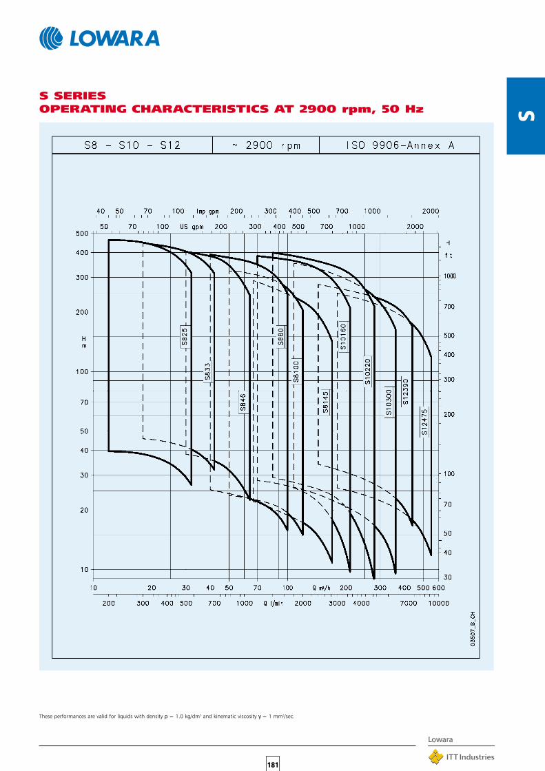
S
181
S SERIESOPERATING CHARACTERISTICS AT 2900 rpm, 50 Hz
These performances are valid for liquids with density ρ = 1.0 kg/dm3 and kinematic viscosity γ = 1 mm2/sec.

APPLICATIONS•Emptying of residential sump pits, rainwater tanks or
laundry drainage.
•Garden and lawn irrigation, with suction from rainwatertanks.
•Emergency draining of flooded basements and garages.
•Transfer of water from tanks, cistems and swimmingpools.
•Water display, fountains.
SPECIFICATIONS•Maximum liquid temperature: 40°C with
partially submerged pump.
•Dry motor.
•Maximum immersion depth: 5 m.
•Class B insulation.
• IP 68 protection.
•The DOC 3 pump has a delivery of 145 l/min, headup to 7 m, and passes suspended solids up to10 mm in diameter. Only available in single-phaseversion.
•The DOC 7 pump has a delivery of 225 l/min, headup to 11 m, and passes suspended solids up to10 mm in diameter.
•The DOC 7VX pump has a delivery of 180 l/min,head up to 7 m, and can handle liquids withsuspended solids up to 20 mm in diameter.
•A “shallow-suction device”, that can be mounted onboth the DOC3 and DOC7 models, is available onrequest. It ensures complete drainage of flooded floors(to 3 mm from floor).
•Versions:Single-phase 220 V 50 Hz 2 poles (2850 rpm).Three-phase 380-415 V 50 Hz 2 poles (2850 rpm).
•60 Hz and without floats (SG) models are available onrequest or tube float switch.
182
DO
C
TABLE OF MATERIALSPART MATERIAL
Pump body,Suction screen,Handle, NORYL TECHNOPOLYMERUpper support,Impeller
Outer sleeve,Motor casing, STAINLESS STEELLower cover, (AISI 304 - DIN 1.4301)Screws and tie-rods
Shaft extension STAINLESS STEEL(AISI 416 - DIN 1.4005)
Elastomers NITRILE RUBBER(NBR)
DOC SERIESSUBMERSIBLE PUMPSDOC pumps are versatile, corrosion-resistant andcompact. Three basic versions are available with0.3 to 0.7 kW power.A DOC 7VX version with Vortex impeller isavailable.
•The single-phase versions feature:Pre-assembled float for automatic pumpoperation (version without float available onrequest SG).Built-in capacitor.Thermal overload protection to stoppump supply in case of overheating.
LAB-LIP SEAL SYSTEM•The electric motor is protected by three lip
seals.An impeller counterblade system keepssolid particles away from the seal unit toprevent damage to the lip seals and ensuretheir long-lasting efficiency. A doubleLabyrinth and a V-ring on the shaft havealso been provided.

183
DO
C
DOC SERIESOPERATING CHARACTERISTICS AT 2850 rpm 50 Hz
PUMP TYPE
l/min 0 25 50 75 100 125 150 175 225
m3/h 0 1.5 3 4.5 6 7.5 9 10.5 13.5
kW HP
RATED
POWER
H = TOTAL HEAD METERS COLUMN OF WATER
Q = DELIVERY
DOC3 0.25 0.33 6.9 6.3 5.6 4.7 3.7 2.5 1.2
DOC7(T) 0.55 0.75 11.1 10.8 10.4 9.9 9.3 8.5 7.6 6.5 3.7
DOC7VX(T) 0.55 0.75 7.2 6.8 6.4 6.0 5.5 4.8 4.1 3.1
Le prestazioni valgono per liquidi con densità ρ = 1,0 kg/dm³ ed una viscosità cinematica ν = 1 mm²/s. doc-2p50_a_th
PUMP TYPE INPUT INPUT CAPACITOR PUMP TYPE
POWER* CURRENT*
220-240 V
A
220-240 V 380-415 V
kW µF / 450 V kW A A
220-240 V THREE-PHASE 220-240 V 380-415 V
kW A µF / 450 V kW A A
SINGLE-PHASE
INPUT
POWER*
INPUT
CURRENT*
INPUT
CURRENT*
DOC 3 0.31 1.43 6.3 - - - -
DOC 7 0.78 3.47 16 DOC 7T 0.79 2.82 1.63
DOC 7VX 0.66 2.96 16 DOC 7VXT 0.66 2.68 1.55
*Valori massimi nel campo di funzionamento doc-2p50_a_te
These performances are valid for liquids with density ρ = 1.0 kg/dm3 and kinematic viscosity γ = 1 mm2/sec.
* Maximum value in specified range

184
DO
C
DOC3 390 330 50 310
DOC7 390 370 90 350
DOC7VX 390 395 115 375
docliv-2p50_a_td
PUMP TYPE
A B C D
WATER
LEVEL
MINIMUM MAXIMUMDIMENSIONS (mm)
WATER
LEVEL
INSTALLATION DIAGRAM
DOC SERIES DIMENSIONS AND WEIGHTS
ACCESSORIES
This float switch allows the pump to be used where standardfloat design cannot work due to insufficient space. The pumpwith this system can only be installed vertically and can only beused with clean water.For pump installations that use the tube float switch, the levelof start and stop are fixed, therefore they cannot be modified.
PUMP TYPE DIMENSIONS (mm) WEIGHT
F H X* kg
DOC3 245 188 20 4
DOC7(T) 285 228 20 6
DOC7VX(T) 310 252 45 6
* Livello minimo di svuotamento. doc-2p50_a_td
0144
6_B_
DD
0143
3_B_
DD
* Minimum liquid level
Lower suction device
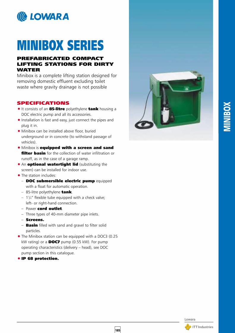
185
MIN
IBOX
MINIBOX SERIESPREFABRICATED COMPACTLIFTING STATIONS FOR DIRTYWATERMinibox is a complete lifting station designed forremoving domestic effluent excluding toiletwaste where gravity drainage is not possible
SPECIFICATIONS•It consists of an 85-litre polyethylene tank housing a
DOC electric pump and all its accessories.
•Installation is fast and easy, just connect the pipes andplug it in.
•Minibox can be installed above floor, buriedunderground or in concrete (to withstand passage ofvehicles).
•Minibox is equipped with a screen and sandfilter basin for the collection of water infiltration orrunoff, as in the case of a garage ramp.
•An optional watertight lid (substituting thescreen) can be installed for indoor use.
•The station includes:– DOC submersible electric pump equipped
with a float for automatic operation.– 85-litre polyethylene tank.– 11/4” flexible tube equipped with a check valve;
left- or right-hand connection.– Power cord outlet.– Three types of 40-mm diameter pipe inlets.– Screens.– Basin filled with sand and gravel to filter solid
particles.
•The Minibox station can be equipped with a DOC3 (0.25kW rating) or a DOC7 pump (0.55 kW). For pumpoperating characteristics (delivery – head), see DOCpump section in this catalogue.
• IP 68 protection.

186
MIN
IBOX
MINIBOX SERIES DIMENSIONS
APPLICATION ILLUSTRATION
EXAMPLE OF MINIBOX APPLICATION

187
DIW
A
DIWA SERIESSUBMERSIBLE PUMPS FORDIRTY WATERSubmersible pumps for dirty water manufacturedin AISI 304 stainless steel. Head up to 20 metres,delivery up to 425 l/min(25,2 m3/h).Four basic models with 0.55 (0.75 HP) to1.5 kW (2HP) rated power.DRIVELUB SEAL SYSTEM
❏ MOTOR COOLED BY PUMPED LIQUID❏ DIFFUSER PLATE COATED WITH
POLYURETHANE FOR MAXIMUMRESISTANCE TO ABRASION
❏ COMPACT AND LIGHTWEIGHT
APPLICATIONS•Draining of cellars, garages, basements.•Draining of construction sites.•Emptying of tanks and reservoirs.•Lawn and garden irrigation.•Fountains.•Pumping of domestic wastewater (washing machines,
showers, sinks).•Emptying of tanks in industrial and ecological
applications.•Water display, fountains.
SPECIFICATIONS•Liquid temperature up to 50°C.•Open impeller.•Minimum level of pumped liquid: 25 mm.•Suspended solids handled up to 8 mm.•Maximum immersion depth: 7m.•10 meters of HO7RN-F type neoprene power cord.•Dry motor (class F insulation).• IP 68 protection.•Versions:
Single-phase 220-240 V 50 Hz 2 poles with built-inoverload protection.Three-phase 380-415 V 50 Hz 2 poles.
•Motor power:– 0.55 to 1.1 kW for single-phase version.– 0.55 to 1.5 kW for three-phase version.
•The single-phase versions feature:Pre-assembled float (version without floatavailable on request).Built-in capacitor (except for DIWA 11 model withcontrol box on cable).Thermal overload protection.
•60 Hz and versions without float (SG) available.
TABLE OF MATERIALSPART MATERIAL
Pump bodyMotor casingOuter sleeve STAINLESS STEELImpeller (AISI 304 - DIN 1.4301)Shaft extensionSuction screenNuts and boltsFront diffuser plate STAINLESS STEEL
(AISI 304 - DIN 1.4301)COATED WITHPOLYURETHANE
ELASTOMERInner mechanical seal SILICON CARBIDE/
SILICON CARBIDEUpper lip seal,
NITRILE RUBBERElastomersHandle STAINLESS STEEL
(AISI 304 - DIN 1.4301)COATED WITH
POLYACETAL RESINS
DRIVELUB SEAL SYSTEMWatertight electric motor protected by multipleseal system with oil chamber.A V-ring and silicon carbidemechanical seal (extremely resistant to wearand abrasion), as well as a lip seal which iscontinuously lubricated by the DRIVELUBsystem, provide an extremely efficient barrieragainst infiltration.

188
DIW
A
DIWA SERIESOPERATING CHARACTERISTICS AT 2850 rpm 50 Hz
PUMP TYPE
l/min 0 100 125 150 175 200 225 250 300 325 375 420
m3/h 0 6 7.5 9 10.5 12 13.5 15 18 19.5 22.5 25.2
kW HP
RATED
POWER
Q = DELIVERY
H = TOTAL HEAD METERS COLUMN OF WATER
DIWA 05(T) 0.55 0.75 10.9 8.6 7.9 7.1 6.3 5.5 4.7 3.8
DIWA 07(T) 0.75 1 14.0 11.2 10.5 9.8 9.0 8.3 7.4 6.6 4.8 3.9
DIWA 11(T) 1.1 1.5 16.1 13.4 12.7 11.9 11.1 10.2 9.4 8.5 6.7 5.8 4.0
DIWA 15T 1.5 2 20.6 17.3 16.4 15.6 14.8 14.0 13.1 12.2 10.4 9.4 7.3 5.3
Le prestazioni valgono per liquidi con densità r = 1,0 kg/dm³ ed una viscosità cinematica n = 1 mm²/s. diwa-2p50_a_th
PUMP TYPE INPUT INPUT CAPACITOR PUMP TYPE
POWER* CURRENT*
220-240 V
A
220-240 V 380-415 V
kW µF / 450 V kW A A
220-240 V THREE-PHASE 220-240 V 380-415 V
kW A µF / 450 V kW A A
SINGLE-PHASE
INPUT
POWER*
INPUT
CURRENT*
INPUT
CURRENT*
DIWA 05 0.79 3.92 16 DIWA 05T 0.72 2.56 1.48
DIWA 07 1.25 6.20 22 DIWA 07T 1.2 4.26 2.46
DIWA 11 1.53 6.83 30 DIWA 11T 1.44 4.64 2.68
- - - - DIWA 15T 2.05 6.74 3.89
*Valori massimi nel campo di funzionamento diwa-2p50_a_te
These performances are valid for liquids with density ρ = 1.0 kg/dm3 and kinematic viscosity γ = 1 mm2/sec.
* Maximum value in specified range

189
DIW
A
DIWA SERIES DIMENSIONS AND WEIGHTS
PUMP TYPE WEIGHT
L1 kgH2 L
DIMENSIONS (mm)
H
DIWA05 370 12
DIWA07 425 14.3
DIWA11 425 17
DIWA05T - 11
DIWA07T - 13
DIWA11T - 15
DIWA15T - 16.5
diwa-2p50_a_td
514
514
459
-
-
-
-
-
-
-
485
485
425343
388
388
343
358
388
388 -
ON
OFF
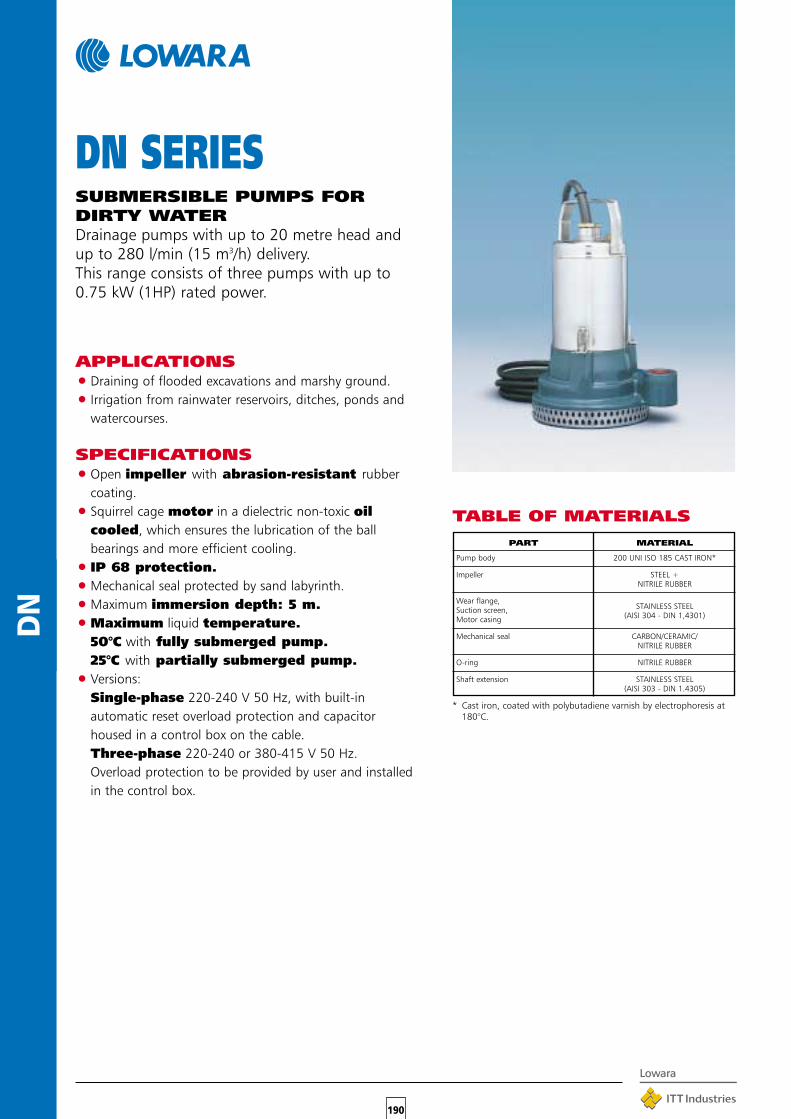
190
DN
TABLE OF MATERIALS
DN SERIESSUBMERSIBLE PUMPS FORDIRTY WATERDrainage pumps with up to 20 metre head andup to 280 l/min (15 m3/h) delivery.This range consists of three pumps with up to0.75 kW (1HP) rated power.
APPLICATIONS•Draining of flooded excavations and marshy ground.
•Irrigation from rainwater reservoirs, ditches, ponds andwatercourses.
SPECIFICATIONS•Open impeller with abrasion-resistant rubber
coating.
•Squirrel cage motor in a dielectric non-toxic oilcooled, which ensures the lubrication of the ballbearings and more efficient cooling.
• IP 68 protection.
•Mechanical seal protected by sand labyrinth.
•Maximum immersion depth: 5 m.
•Maximum liquid temperature.50°C with fully submerged pump.25°C with partially submerged pump.
•Versions:Single-phase 220-240 V 50 Hz, with built-inautomatic reset overload protection and capacitorhoused in a control box on the cable.Three-phase 220-240 or 380-415 V 50 Hz.Overload protection to be provided by user and installedin the control box.
PART MATERIAL
Pump body 200 UNI ISO 185 CAST IRON*
Impeller STEEL +NITRILE RUBBER
Wear flange,STAINLESS STEELSuction screen,
(AISI 304 - DIN 1,4301)Motor casing
Mechanical seal CARBON/CERAMIC/NITRILE RUBBER
O-ring NITRILE RUBBER
Shaft extension STAINLESS STEEL(AISI 303 - DIN 1.4305)
* Cast iron, coated with polybutadiene varnish by electrophoresis at180°C.

191
DN
DN SERIESOPERATING CHARACTERISTICS AT 2850 rpm 50 Hz
PUMP TYPE
l/min 0 25 50 75 100 125 150 175 210 225 250 280
m3/h 0 1.5 3 4.5 6 7.5 9 10.5 12.6 13.5 15 16.8
kW HP
RATED
POWER
Q = DELIVERY
H = TOTAL HEAD METERS COLUMN OF WATER
DN(M) 110 0.6 0.8 11.5 11.0 10.4 9.8 9.1 8.3 7.3 6.3 4.5
DN(M) 115 0.6 0.8 16.2 15.6 14.9 14.1 13.3 12.4 11.4 10.3 8.6 7.8 6.4
DN(M) 120 0.75 1 22.0 21.1 20.1 19.1 18.0 16.8 15.6 14.2 12.1 11.2 9.5 7.3
Le prestazioni valgono per liquidi con densità ρ = 1,0 kg/dm³ ed una viscosità cinematica ν = 1 mm²/s. dn-2p50_a_th
PUMP TYPE INPUT INPUT CAPACITOR PUMP TYPE
POWER* CURRENT*
220-240 V
A
220-240 V 380-415 V
kW µF / 450 V kW A A
220-240 V THREE-PHASE 220-240 V 380-415 V
kW A µF / 450 V kW A A
SINGLE-PHASE
INPUT
POWER*
INPUT
CURRENT*
INPUT
CURRENT*
DNM 110 0.68 3.56 25 DN 110 0.66 - 2.00
DNM 115 0.90 4.28 25 DN 115 0.93 - 2.20
DNM 120 1.03 4.77 25 DN 120 1.09 4.05 2.34
*Valori massimi nel campo di funzionamento dn-2p50_a_te
These performances are valid for liquids with density ρ = 1.0 kg/dm3 and kinematic viscosity γ = 1 mm2/sec.
* Maximum value in specified range

192
DN
DN SERIES DIMENSIONS AND WEIGHTS
PUMP TYPE DNM WEIGHT
C H H1 L L1 W W1 kg
DIMENSIONS (mm)
DNM110-DN110 Ø 200 380 81 209 223 81 95 Rp 1¼ 18.5
DNM115-DN115 Ø 200 380 81 209 223 81 95 Rp 1¼ 18.5
DNM120-DN120 Ø 200 380 81 209 223 81 95 Rp 1¼ 19.5
dn-2p50_a_td

•The DOMO 10-15-20 and DOMO 10-15-20VX versions feature:– 2” delivery port, female ASP (can be
turned into a flanged version if anoptional accessory is installed).
– Handling of suspended solids up to50 mm in diameter.
– Stainless steel twin-channel orvortex impeller.
– Tube float switch.
DRIVELUB SEAL SYSTEM•Watertight electric motor protected by multiple
seal system with oil chamber.A V-ring and silicon carbide mechanicalseal (extremely resistant to wear and abrasion),as well as a lip seal which is continuouslylubricated by the DRIVELUB system, providean extremely efficient barrier against infiltration.
APPLICATIONS•Pumping of effluent (VX model handles also suspended
filaments).
•Emptying of septic tanks and residential sumps.
•Draining of flooded basements and garages.•Water display, fountains.
SPECIFICATIONS•Capacity up to 40 m3/h.
•Head up to 14,8 m.
•Continuous duty with 35°C liquids and fullysubmerged pump.
•Dry motor (class F insulation).
• IP 68 protection.
•HO7RN-F type neoprene power cord.
•Maximum immersion depth: 5 m.
•Versions:Single-phase 220-240 V 50 Hz 2 poles.Three-phase 380-415 V 50 Hz 2 poles.
•Motor power:0.55 to 1.1 kW for single-phase versions.0.55 to 1.5 kW for three-phase versions.
•The single-phase versions feature:Pre-assembled float (version without floatavailable on request).Built-in capacitor (except for DOMO 15 andDOMO 15 VX models with control box on cable).Thermal overload protection.
•The DOMO 7 and DOMO 7VX versions feature:– Rp 11/2” delivery port (female gas).– Handling of suspended solids up to 35 mm in
diameter.– Fiberglass-reinforced nylon impeller
(stainless steel impeller also available).
193
DO
MO
DOMO SERIESSUBMERSIBLE PUMPS WITHENTRAINED SOLIDSDOMO series electric pumps are available withtwin-channel or vortex impeller (DOMO VX).Designed to handle suspended solids up to 50mm in diameter (35 mm for DOMO 7 andDOMO 7VX).Four basic models with 0.55 (0.75 HP) to 1.5 kW(2HP) rated power.DRIVELUB SEAL SYSTEM.
TABLE OF MATERIALSPART MATERIAL
Pump body, STAINLESS STEELMotor casing (AISI 304 - DIN 1.4301)
DOMO 7 (VX) impeller FIBREGLASS-REINFORCEDNYLON
DOMO 10-15-20 (VX) impeller STAINLESS STEEL(AISI 304 - DIN 1.4301)
Inner mechanical seal SILICON CARBIDE/SILICON CARBIDE
Upper lip seal NITRILE RUBBER
Shaft extension STAINLESS STEEL(AISI 304 - DIN 1.4301)
Handle NYLON
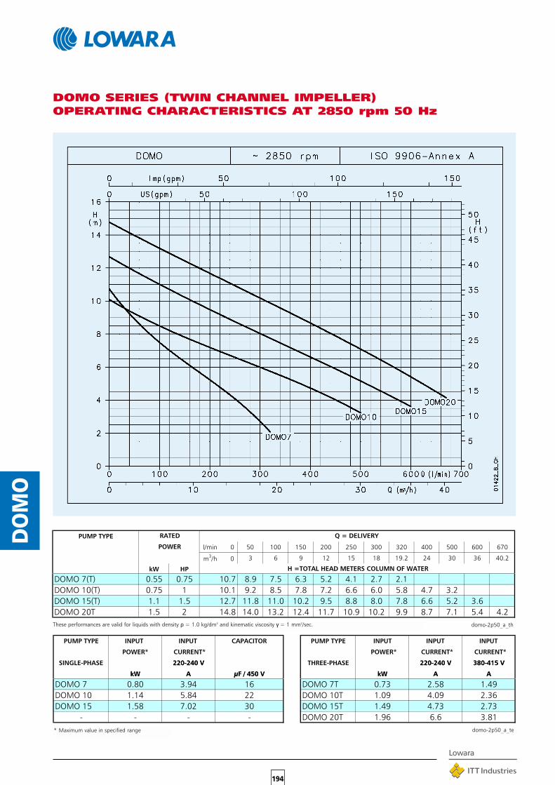
194
DO
MO
DOMO SERIES (TWIN CHANNEL IMPELLER)OPERATING CHARACTERISTICS AT 2850 rpm 50 Hz
PUMP TYPE
l/min 0 50 100 150 200 250 300 320 400 500 600 670
m3/h 0 3 6 9 12 15 18 19.2 24 30 36 40.2
kW HP
RATED
POWER
Q = DELIVERY
H =TOTAL HEAD METERS COLUMN OF WATER
DOMO 7(T) 0.55 0.75 10.7 8.9 7.5 6.3 5.2 4.1 2.7 2.1
DOMO 10(T) 0.75 1 10.1 9.2 8.5 7.8 7.2 6.6 6.0 5.8 4.7 3.2
DOMO 15(T) 1.1 1.5 12.7 11.8 11.0 10.2 9.5 8.8 8.0 7.8 6.6 5.2 3.6
DOMO 20T 1.5 2 14.8 14.0 13.2 12.4 11.7 10.9 10.2 9.9 8.7 7.1 5.4 4.2
Le prestazioni valgono per liquidi con densità r = 1,0 kg/dm³ ed una viscosità cinematica n = 1 mm²/s. domo-2p50_a_th
PUMP TYPE INPUT INPUT CAPACITOR PUMP TYPE
POWER* CURRENT*
220-240 V
A
220-240 V 380-415 V
kW µF / 450 V kW A A
220-240 V THREE-PHASE 220-240 V 380-415 V
kW A µF / 450 V kW A A
SINGLE-PHASE
INPUT
POWER*
INPUT
CURRENT*
INPUT
CURRENT*
DOMO 7 0.80 3.94 16 DOMO 7T 0.73 2.58 1.49
DOMO 10 1.14 5.84 22 DOMO 10T 1.09 4.09 2.36
DOMO 15 1.58 7.02 30 DOMO 15T 1.49 4.73 2.73
- - - - DOMO 20T 1.96 6.6 3.81
*Valori massimi nel campo di funzionamento domo-2p50_a_te
These performances are valid for liquids with density ρ = 1.0 kg/dm3 and kinematic viscosity γ = 1 mm2/sec.
* Maximum value in specified range

195
DO
MO
DOMO VX SERIES (VORTEX IMPELLER)OPERATING CHARACTERISTICS AT 2850 rpm 50 Hz
PUMP TYPE
l/min 0 80 100 150 175 200 225 260 300 400 450 550
m3/h 0 4.8 6 9 10.5 12 13.5 15.6 18 24 27 33
kW HP
RATED
POWER
Q = DELIVERY
H = TOTAL HEAD METERS COLUMN OF WATER
DOMO 7VX(T) 0.55 0.75 9.1 7.1 6.6 5.1 4.4 3.7 3.0 2.0
DOMO 10VX(T) 0.75 1 7.7 7.3 7.1 6.7 6.5 6.2 5.9 5.4 4.8 3.1
DOMO 15VX(T) 1.1 1.5 9.1 8.8 8.6 8.3 8.0 7.8 7.5 7.1 6.5 4.8 3.7
DOMO 20VXT 1.5 2 11.0 10.6 10.5 10.2 9.9 9.7 9.5 9.1 8.6 7.0 6.1 3.8
Le prestazioni valgono per liquidi con densità r = 1,0 kg/dm³ ed una viscosità cinematica n = 1 mm²/s. domovx-2p50_a_th
PUMP TYPE INPUT INPUT CAPACITOR PUMP TYPE
POWER* CURRENT*
220-240 V
A
220-240 V 380-415 V
kW µF / 450 V kW A A
220-240 V THREE-PHASE 220-240 V 380-415 V
kW A µF / 450 V kW A A
SINGLE-PHASE
INPUT
POWER*
INPUT
CURRENT*
INPUT
CURRENT*
DOMO 7VX 0.79 3.91 16 DOMO 7VXT 0.71 2.56 1.48
DOMO 10VX 1.15 5.88 22 DOMO 10VXT 1.10 4.09 2.36
DOMO 15VX 1.36 6.11 30 DOMO 15VXT 1.26 4.31 2.49
- - - - DOMO 20VXT 1.74 6.22 3.59
*Valori massimi nel campo di funzionamento domovx-2p50_a_te
These performances are valid for liquids with density ρ = 1.0 kg/dm3 and kinematic viscosity γ = 1 mm2/sec.
* Maximum value in specified range

196
DO
MO
DOMO SERIES DIMENSIONS AND WEIGHTS
PUMP TYPE DNM WEIGHT
H H1 H2 L L1 C kg
DIMENSIONS (mm)
DOMO7-DOMO7VX 386 88 370 420 275 193 Rp 1½ 10
DOMO10-DOMO10VX 463 111.5 415 495 350 198 Rp 2 13.4
DOMO15-DOMO15VX 463 111.5 415 495 350 198 Rp 2 15.1
DOMO7T-DOMO7VXT 386 88 - - - 193 Rp 1½ 8.7
DOMO10T-DOMO10VXT 433 111.5 - - - 198 Rp 2 11.4
DOMO15T-DOMO15VXT 463 111.5 - - - 198 Rp 2 13.4
DOMO20T-DOMO20VXT 463 111.5 - - - 198 Rp 2 14.4
domo-2p50_a_td
This float switch allows the pump to be used where standardfloat design cannot work due to insufficient space. The pumpwith this system can only be installed vertically and can only beused with clean water.For pump installations that use the tube float switch, the levelof start and stop are fixed, therefore they cannot be modified.
ON
OFF

197
DL
TABLE OF MATERIALS
DL SERIESSUBMERSIBLE PUMPS WITHENTRAINED SOLIDS WASTEWATERDL series electric pumps are available with single-channel or Vortex impeller (DLV).Designed to handle with entrained solidswastewater, with head up to 21 m and deliveryup to 120 m3/h.
APPLICATIONS•Pumping of sewage with suspended solids and
filaments.
•Emptying of sumps, septic tanks and wastewaterdischarge tanks.
•Draining of flooded excavations and marshy ground.•Water display, fountains.
SPECIFICATIONS•Squirrel cage motor in a dielectric non-toxic oil
cooled, which ensures the lubrication of the ballbearings and more efficient cooling.
•2-pole (0.6 to 1.5 kW) and 4-pole (1.8 to 4 kW)motors.
•Mechanical seal protected by sand labyrinth.
•Maximum immersion depth: 5 m.
• IP 68 protection.
•Maximum temperature of pumped liquid:50°C with fully submerged pump.25°C with partially submerged pump.
•Passes solids up to:45 mm (DL 80, 90, 105, Minivortex,Vortex).50 mm (DL 109, 125, 160, DLV 100, 115).60 mm (DL 180, 200).65 mm (DLV 120, 140, 160).
•Versions:Single-phase 220-240 V 50 Hz, with built-inautomatic reset overload protection and capacitor boxwith on/off switch.Three-phase 220-240 or 380-415 V 50 Hz forpumps up to 4 kW.Overload protection to be provided by user (installed inthe control box).
•Pre-assembled float available on request (single-phaseversions DL…CG, DLV…CG).
PART MATERIAL
Pump body 200 UNI ISO 185 CAST IRON*
Impeller STAINLESS STEEL(AISI 304 - DIN 1.4301)
200 UNI ISO 185 CAST IRON* FORMINIVORTEX AND VORTEX
Suction flange,Support feet, STAINLESS STEELShaft (extension), (AISI 304 - DIN 1.4301)Motor casing
O-Ring NITRILE RUBBER
Mechanical seal CARBON/CERAMIC/NITRILE RUBBER
Delivery seal 200 UNI ISO 185 CAST IRON*(DL 109,125 and DLV 100, 115)
PART MATERIAL
Pump body, Impeller,200 UNI ISO 185 CAST IRON*Motor-pump support
Shaft STAINLESS STEEL(AISI 420 - DIN 1.4021)
Motor casing,Motor cover, STAINLESS STEELHandle tie rod with bracket, (AISI 304 - DIN 1.4301)Base
Mechanical seal TUNGSTENE CARBIDE/TUNGSTENE CARBIDE/ FPM
O-Ring NITRILE RUBBER
2 POLES PUMPS:DL 80, 90, 105, 109, 125; MINIVORTEX andVORTEX, DLV 100, 115
4 POLES PUMPS:DL 160, 180, 200 and DLV 120, 140, 150
* Cast iron coated with polybutadiene varnish by electrophoresis at180°C.

198
DL SERIES (SINGLE-CHANNEL IMPELLER)OPERATING CHARACTERISTICS AT 2850 rpm 50 Hz
PUMP TYPE
l/min 0 100 150 200 250 300 350 400 450 500 600 700
m3/h 0 6 9 12 15 18 21 24 27 30 36 42
kW HP
RATED
POWER
Q = DELIVERY
H = TOTAL HEAD METERS COLUMN OF WATER
DL(M) 80 0.6 0.8 7.6 5.9 5.3 4.7 4.1 3.6 3.0
DL(M) 90 0.6 0.8 9.7 7.8 7.0 6.4 5.8 5.3 4.7 4.1 3.5
DL 105 1.1 1.5 14.1 11.6 10.6 9.7 8.9 8.1 7.4 6.7 5.9 5.2
DL(M) 109 1.1 1.5 18.3 15.4 14.2 13.1 12.0 11.0 10.1 9.2 8.2 7.3 5.4
DL 125 1.5 2 21.9 19.2 17.9 16.7 15.5 14.4 13.4 12.3 11.3 10.3 8.4 6.5
Le prestazioni valgono per liquidi con densità ρ = 1,0 kg/dm³ ed una viscosità cinematica ν = 1 mm²/s. dl-2p50_a_th
DLM 80 0.79 3.91 25 DL 80 0.8 - 2.09
DLM 90 0.89 4.27 25 DL 90 0.92 3.81 2.2
- - - - DL 105 1.43 4.66 2.69
DLM109 1.55 6.87 35 DL 109 1.54 5.44 3.14
- - - - DL 125 2.14 6.58 3.8
*Valori massimi nel campo di funzionamento dl-2p50_a_te
These performances are valid for liquids with density ρ = 1.0 kg/dm3 and kinematic viscosity γ = 1 mm2/sec.
PUMP TYPE INPUT INPUT CAPACITOR PUMP TYPE
POWER* CURRENT*
220-240 V
A
220-240 V 380-415 V
kW µF / 450 V kW A A
220-240 V THREE-PHASE 220-240 V 380-415 V
kW A µF / 450 V kW A A
SINGLE-PHASE
INPUT
POWER*
INPUT
CURRENT*
INPUT
CURRENT*
DL
* Maximum value in specified range

199
DL
DLV SERIES (VORTEX IMPELLER)OPERATING CHARACTERISTICS AT 2850 rpm 50 Hz
PUMP TYPE
l/min 0 50 100 150 200 250 300 350 400 450 500 600
m3/h 0 3 6 9 12 15 18 21 24 27 30 36
kW HP
RATED
POWER
Q = DELIVERY
H = TOTAL HEAD METERS COLUMN OF WATER
MINI VORTEX(M) 0.6 0.8 7.2 6.3 5.5 4.8 4.0 3.0 1.8
VORTEX 1.1 1.5 8.4 8.0 7.6 7.2 6.8 6.3 5.8 5.1 4.4 3.5 2.5
DLV(M) 100 1.1 1.5 10.6 10.1 9.6 9.1 8.6 8.0 7.4 6.6 5.8 4.8 3.7
DLV 115 1.5 2 13.1 12.5 12.0 11.5 11.0 10.5 9.9 9.3 8.5 7.7 6.6 4.0
Le prestazioni valgono per liquidi con densità ρ = 1,0 kg/dm³ ed una viscosità cinematica ν = 1 mm²/s. dlv-2p50_a_th
PUMP TYPE INPUT INPUT CAPACITOR PUMP TYPE
POWER* CURRENT*
220-240 V
A
220-240 V 380-415 V
kW µF / 450 V kW A A
THREE-PHASESINGLE-PHASE
INPUT
POWER*
INPUT
CURRENT*
INPUT
CURRENT*
MINI VORTEX M 1.05 4.82 25 MINI VORTEX 1.10 - 2.36
- - - - VORTEX 1.66 5.11 2.95
DLVM100 1.64 7.30 35 DLV 100 1.65 5.63 3.25
- - - - DLV 115 2.25 6.81 3.93
*Valori massimi nel campo di funzionamento dlv-2p50_a_te
These performances are valid for liquids with density ρ = 1.0 kg/dm3 and kinematic viscosity γ = 1 mm2/sec.
* Maximum value in specified range

200
DL
SERIE DL (SINGLE-CHANNEL IMPELLER)OPERATING CHARACTERISTICS AT 1450 rpm 50 Hz
PUMP TYPE
l/min 0 500 750 1000 1250 1400 1750 2000
m3/h 0 30 45 60 75 84 105 120
kW HP H = TOTAL HEAD METERS COLUMN OF WATER
RATED
POWER
Q = DELIVERY
DL 160 1.85 2.5 11.3 7.3 6.3 5.3 4.0
DL 180 2.75 3.75 12.7 9.2 8.0 7.0 6.2 5.7 4.2
DL 200 4 5.5 15.5 12.0 10.7 9.6 8.6 8.0 6.2 5.3
Le prestazioni valgono per liquidi con densità ρ = 1,0 kg/dm³ ed una viscosità cinematica ν = 1 mm²/s. dl4-4p50_a_th
PUMP TYPE INPUT INPUT CAPACITOR PUMP TYPE
POWER* CURRENT*
220-240 V
A
220-240 V 380-415 V
kW µF / 450 V kW A A
220-240 V THREE-PHASE 220-240 V 380-415 V
kW A µF / 450 V kW A A
SINGLE-PHASE
INPUT
POWER*
INPUT
CURRENT*
INPUT
CURRENT*
- - - - DL160 2.1 6 3.5
- - - - DL180 3.2 10 5.8
- - - - DL200 4.7 15 8.7
*Valori massimi nel campo di funzionamento dl4-4p50_a_te
These performances are valid for liquids with density ρ = 1.0 kg/dm3 and kinematic viscosity γ = 1 mm2/sec.
* Maximum value in specified range

201
DL
DLV SERIES (VORTEX IMPELLER)OPERATING CHARACTERISTICS AT 1450 rpm 50 Hz
PUMP TYPE
l/min 0 500 750 1000 1250 1400 1750 2000
m3/h 0 30 45 60 75 84 105 120
kW HP H = TOTAL HEAD METERS COLUMN OF WATER
RATED
POWER
Q = DELIVERY
DLV 120 1.85 2.5 7.0 6.7 6.0 5.0 3.8
DLV 140 2.75 3.75 8.8 8.6 8.1 7.4 6.4 6.0 5.3 4.7
DLV 150 4 5.5 12.5 11.5 10.2 8.7 7.2 6.6 5.7 5.0
Le prestazioni valgono per liquidi con densità ρ = 1,0 kg/dm³ ed una viscosità cinematica ν = 1 mm²/s. dlv-4p50_a_th
PUMP TYPE INPUT INPUT CAPACITOR PUMP TYPE
POWER* CURRENT*
220-240 V
A
220-240 V 380-415 V
kW µF / 450 V kW A A
220-240 V THREE-PHASE 220-240 V 380-415 V
kW A µF / 450 V kW A A
SINGLE-PHASE
INPUT
POWER*
INPUT
CURRENT*
INPUT
CURRENT*
- - - - DLV120 2.3 7.8 4.5
- - - - DLV140 3.4 11.2 6.5
- - - - DLV150 4.9 16.5 9.5
*Valori massimi nel campo di funzionamento dlv-4p50_a_te
These performances are valid for liquids with density ρ = 1.0 kg/dm3 and kinematic viscosity γ = 1 mm2/sec.
* Maximum value in specified range

202
DL
2 POLES DL(V) SERIES DIMENSIONS AND WEIGHTS
PUMP TYPE WEIGHT
kg
DL80-DLM80
DL90-DLM90
DL105
MINIVORTEX (M)
VORTEX
dl-vortex-2p50_a_td
19
19.0
19.5
20
21
PUMP TYPE WEIGHT
kg
DL109-DLM109
DL125
DLV100-DLVM100
DLV115
dl-dlv-2p50_a_td
27
27
27
27

203
DL
4 POLES DL(V) SERIES DIMENSIONS AND WEIGHTS
PUMP TYPE DNM WEIGHT
A B C D H kg
DIMENSIONS (mm)
DL 160 735 432 314 177 275 Ø 80 78
DL 180 835 470 391 182 275 Ø 80 103
DL 200 885 470 391 182 275 Ø 80 111
DLV 120 760 409 268 183 275 Ø 80 76
DLV 140 820 409 268 183 275 Ø 80 77
DLV 150 865 345 380 160 180 Ø 80 116
dl(v)-4p50_a_td
PUMP TYPE
A B C D E F G
DIMENSIONS (mm)
DL 160 667 525 337 314 540 85 368
DL 180 705 563 337 391 636 80 368
DL 200 705 563 337 391 686 80 368
DLV 120 645 503 337 268 558 78 368
DLV 140 645 503 337 268 618 78 368
DLV 150 580 438 242 380 690 106 273
dl(v)4-4p50_a_td
ø 18
n°
HO
LES

204
GL-
GLV
GL-GLV SERIESSUBMERSIBLE ELECTRICPUMPS FOR WASTE WATERS
APPLICATIONS•Circulation of sewage water containing suspended
solids.
•Emptying of domestic waste water tanks, dirty waterfrom cesspools and sewage water in general.
•Drainage of excavations and marshy grounds.
FEATURES•Manufactured in cast iron - shaft and impeller in 304
stainless steel.
•Motor stator installed non-toxic, dielectric oilfor the lubrication of the ball bearings and improvedcooling.
•Volute pump casing.
•Mechanical seal protected by sand-prooflabyrinth.
•Maximum depth of immersion: 5 meters.
•Maximum liquid temperature: 50°C with pumpwholly submersed.30°C with pump partially submersed.
•Motor class F - IP68 - 2900 rpm.
•Single-channel or vortex impeller - cross-section Ø 50mm.
•Starting panel in the single-phase bersion.
•Version:Single-phase 220-230 V 50 Hz.Three-phase 220-240 V, 50 Hz or 380-415 V 50 Hz.
TABLE OF MATERIALSCOMPONENT MATERIAL
Pump casing CAST IRON* 200 UNI ISO 185
Impeller CrNi STEEL(AISI 304)
Suction flange CrNi STEEL(AISI 304)
Support foot CrNi STEEL(AISI 304)
O-Ring NITRILE RUBBER
Mechanical seal CARBON/CERAMIC/NITRILE RUBBER
Shaft extension CrNi STEEL(AISI 304)
Motor casing CAST IRON* 200 UNI ISO 185
* Cast iron with polybutadiene surface treatment forelectrophoresis at 180°C
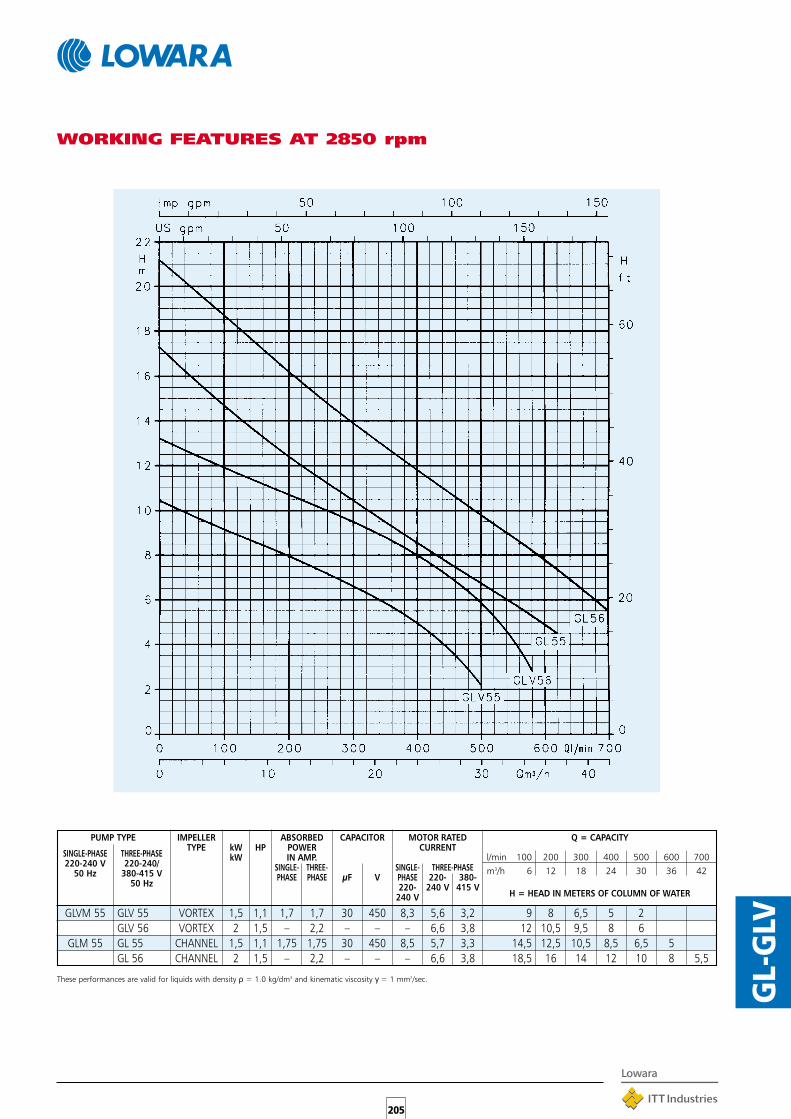
205
GL-
GLV
WORKING FEATURES AT 2850 rpm
SINGLE-PHASE THREE-PHASE
IMPELLER ABSORBED CAPACITOR MOTOR RATED
220-240 V 220-240/
TYPE kW HP POWER CURRENT
50 Hz 380-415 V
kW IN AMP.
50 Hz
SINGLE- THREE- SINGLE- THREE-PHASEPHASE PHASE µF V PHASE 220- 380-
220- 240 V 415 V240 V
Q = CAPACITY
l/min 100 200 300 400 500 600 700m3/h 6 12 18 24 30 36 42
H = HEAD IN METERS OF COLUMN OF WATER
GLVM 55 GLV 55 VORTEX 1,5 1,1 1,7 1,7 30 450 8,3 5,6 3,2GLV 56 VORTEX 2 1,5 – 2,2 – – – 6,6 3,8
GLM 55 GL 55 CHANNEL 1,5 1,1 1,75 1,75 30 450 8,5 5,7 3,3GL 56 CHANNEL 2 1,5 – 2,2 – – – 6,6 3,8
9 8 6,5 5 212 10,5 9,5 8 6
14,5 12,5 10,5 8,5 6,5 518,5 16 14 12 10 8 5,5
PUMP TYPE
These performances are valid for liquids with density ρ = 1.0 kg/dm3 and kinematic viscosity γ = 1 mm2/sec.
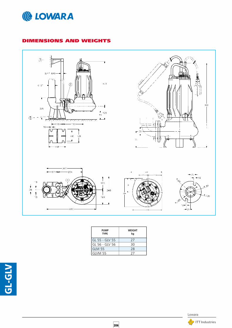
206
GL-
GLV
GL 55 - GLV 55 27GL 56 - GLV 56 30GLM 55 28GLVM 55 27
DIMENSIONS AND WEIGHTS
PUMP WEIGHTTYPE kg

207 SIN
GLE
BOX
DO
UBL
EBO
XSI
NG
LEBO
XD
OU
BLEB
OX
SINGLEBOXDOUBLEBOX SERIESPREFABRICATED LIFTINGSTATIONS WITH ENTRAINEDSOLIDS WASTE WATERThe ideal solution when domestic wastewatermust be delivered to sewer mains located at ahigher level, or where gravity drainage is notpossible.
SPECIFICATIONS•The pumping station, installed in the basement or
buried outdoors, collects domestic effluent (toiletincluded) without any need for initial treatment.
•SINGLEBOX consists of a 230-litre polyethylenebasin housing a vortex (DLV) or single-channel (DL)sewage pump, a control box and float. It is a completepumping station equipped with a lowering device.
•Where greater capacity is required use DOUBLEBOX,a prefabricated lifting station which has twice thecapacity of Biobox (450 litres) and is designedto house two pumps. The operating principle is thesame but it produces higher heads.
•The system consists of:230-litre (450 for Doublebox) polyethylene basin withscrew down lid.Cable glands for power supply cords (and float)and installation of cables under the cover.2” delivery pipe.Six inlets for discharge or ventilation.DOMO or DL submersible pump, vortex orchannel type.Lowering device.Vent or emergency drain plug.Control box.
•IP 68 protection.
•Accessories available on request:- Pump kit available to be put into box- Ball valve- Alarm float.
•For operating characteristics (delivery – head)see DOMO and DL pump section in thiscatalogue.

208SIN
GLE
BOX
DO
UBL
EBO
X
TECHNICAL DATA
kW HP
Q m
ax (
l/m
in)
H m
ax (
m)
Imp
eller
typ
e
Co
ntr
ol p
an
el Q
DR
Flo
at
swit
ch p
re-a
ssem
ble
d
on
pu
mp
Flo
at
sw
itch
(5-m
cab
le)
No
n-r
etu
rn v
alv
e
Em
erg
en
cy f
loat
sw
itch
Sir
en
Fla
sh
ing
lig
ht
SINGLEBOX DOMO 7 0.55 0.75 320 10.7 TWIN CHANNEL X X
SINGLEBOX DOMO 7VX 0.55 0.75 260 9.1 VORTEX X X
SINGLEBOX DOMO 10 0.75 1 500 10.1 TWIN CHANNEL X X
SINGLEBOX DOMO 10VX 0.75 1 400 7.7 VORTEX X X
SINGLEBOX DOMO 15 1.1 1.5 600 12.7 TWIN CHANNEL X X
SINGLEBOX DOMO 15VX 1.1 1.5 450 9.1 VORTEX X X
SINGLEBOX DOMO 7T 0.55 0.75 320 10.7 TWIN CHANNEL X X X X X X
SINGLEBOX DOMO 7VXT 0.55 0.75 260 9.1 VORTEX X X X X X X
SINGLEBOX DOMO 10T 0.75 1 500 10.1 TWIN CHANNEL X X X X X X
SINGLEBOX DOMO 10VXT 0.75 1 400 7.7 VORTEX X X X X X X
SINGLEBOX DOMO 15T 1.1 1.5 600 12.7 TWIN CHANNEL X X X X X X
SINGLEBOX DOMO 15VXT 1.1 1.5 450 9.1 VORTEX X X X X X X
SINGLEBOX DOMO 20T 1.5 2 670 14.8 TWIN CHANNEL X X X X X X
SINGLEBOX DOMO 20VXT 1.5 2 550 11 VORTEX X X X X X X
SINGLEBOX DOMO 10 0.75 1 500 10.1 TWIN CHANNEL X X
SINGLEBOX DOMO 10VX 0.75 1 400 7.7 VORTEX X X
SINGLEBOX DOMO 15 1.1 1.5 600 12.7 TWIN CHANNEL X X
SINGLEBOX DOMO 15VX 1.1 1.5 450 9.1 VORTEX X X
SINGLEBOX DOMO 10T 0.75 1 500 10.1 TWIN CHANNEL X X X X X X
SINGLEBOX DOMO 10VXT 0.75 1 400 7.7 VORTEX X X X X X X
SINGLEBOX DOMO 15T 1.1 1.5 600 12.7 TWIN CHANNEL X X X X X X
SINGLEBOX DOMO 15VXT 1.1 1.5 450 9.1 VORTEX X X X X X X
SINGLEBOX DOMO 20T 1.5 2 670 14.8 TWIN CHANNEL X X X X X X
SINGLEBOX DOMO 20VXT 1.5 2 550 11 VORTEX X X X X X X
SINGLEBOX DLM 80 0.6 0.8 350 7.6 SINGLE CHANNEL X X
SINGLEBOX DLM 90 0.6 0.8 450 9.7 SINGLE CHANNEL X X
SINGLEBOX MINI VORTEX M 0.6 0.8 300 7.2 VORTEX X X
SINGLEBOX DLM 109 1.1 1.5 600 18.3 SINGLE CHANNEL X X
SINGLEBOX DLVM 100 1.1 1.5 500 10.6 VORTEX X X
SINGLEBOX DL 80 0.6 0.8 350 7.6 SINGLE CHANNEL X X X X X X
SINGLEBOX DL 90 0.6 0.8 450 9.7 SINGLE CHANNEL X X X X X X
SINGLEBOX MINI VORTEX 0.6 0.8 300 7.2 VORTEX X X X X X X
SINGLEBOX DL 105 1.1 1.5 500 14.1 SINGLE CHANNEL X X X X X X
SINGLEBOX DL 109 1.1 1.5 600 18.3 SINGLE CHANNEL X X X X X X
SINGLEBOX DLV 100 1.1 1.5 500 10.6 VORTEX X X X X X X
SINGLEBOX VORTEX 1.1 1.5 500 8.4 VORTEX X X X X X X
SINGLEBOX DL 125 1.5 2 700 21.9 SINGLE CHANNEL X X X X X X
SINGLEBOX DLV 115 1.5 2 600 13.1 VORTEX X X X X X X
sbox_models_a_sc
Notes
ACCESSORIES
Single-phase model pumps come with start capacitor, overload protection, float switch and cord
with plug.
Versions with control panel and accessories are available on request
FEATURED
COMPONENTSCHARACTERISTICS
Check with
sales network
Check with
sales network
Check with
sales network
SIN
GL
E-P
HA
SE
SINGLEBOXF
IXED
PV
C P
IPE F
ITT
ING
S
SIN
GL
E-P
HA
SE
DR
OP
CA
BL
E
SIN
GL
E-P
HA
SE
TH
RE
E-P
HA
SE
TH
RE
E-P
HA
SE
TH
RE
E-P
HA
SE

209 SIN
GLE
BOX
DO
UBL
EBO
X
TECHNICAL DATA
DOUBLEBOX DOMO 7 2x0.55 2x0.75 640 10.7 TWIN CHANNEL X X
DOUBLEBOX DOMO 7VX 2x0.55 2x0.75 520 9.1 VORTEX X X
DOUBLEBOX DOMO 10 2x0.75 2x1 1000 10.1 TWIN CHANNEL X X
DOUBLEBOX DOMO 10VX 2x0.75 2x1 800 7.7 VORTEX X X
DOUBLEBOX DOMO 15 2x1.1 2x1.5 1200 12.7 TWIN CHANNEL X X
DOUBLEBOX DOMO 15VX 2x1.1 2x1.5 900 9.1 VORTEX X X
DOUBLEBOX DOMO 7T 2x0.55 2x0.75 640 10.7 TWIN CHANNEL X X X X X X
DOUBLEBOX DOMO 7VXT 2x0.55 2x0.75 520 9.1 VORTEX X X X X X X
DOUBLEBOX DOMO 10T 2x0.75 2x1 1000 10.1 TWIN CHANNEL X X X X X X
DOUBLEBOX DOMO 10VXT 2x0.75 2x1 800 7.7 VORTEX X X X X X X
DOUBLEBOX DOMO 15T 2x1.1 2x1.5 1200 12.7 TWIN CHANNEL X X X X X X
DOUBLEBOX DOMO 15VXT 2x1.1 2x1.5 900 9.1 VORTEX X X X X X X
DOUBLEBOX DOMO 20T 2x1.5 2x2 1340 14.8 TWIN CHANNEL X X X X X X
DOUBLEBOX DOMO 20VXT 2x1.5 2x2 1100 11 VORTEX X X X X X X
DOUBLEBOX DOMO 10 2x0.75 2x1 1000 10.1 TWIN CHANNEL X X
DOUBLEBOX DOMO 10VX 2x0.75 2x1 800 7.7 VORTEX X X
DOUBLEBOX DOMO 15 2x1.1 2x1.5 1200 12.7 TWIN CHANNEL X X
DOUBLEBOX DOMO 15VX 2x1.1 2x1.5 900 9.1 VORTEX X X
DOUBLEBOX DOMO 10T 2x0.75 2x1 1000 10.1 TWIN CHANNEL X X X X X X
DOUBLEBOX DOMO 10VXT 2x0.75 2x1 800 7.7 VORTEX X X X X X X
DOUBLEBOX DOMO 15T 2x1.1 2x1.5 1200 12.7 TWIN CHANNEL X X X X X X
DOUBLEBOX DOMO 15VXT 2x1.1 2x1.5 900 9.1 VORTEX X X X X X X
DOUBLEBOX DOMO 20T 2x1.5 2x2 1340 14.8 TWIN CHANNEL X X X X X X
DOUBLEBOX DOMO 20VXT 2x1.5 2x2 1100 11 VORTEX X X X X X X
DOUBLEBOX DLM 80 2x0.6 2x0.8 700 7.6 SINGLE CHANNEL X X X X X X
DOUBLEBOX DLM 90 2x0.6 2x0.8 900 9.7 SINGLE CHANNEL X X X X X X
DOUBLEBOX MINI VORTEX M 2x0.6 2x0.8 600 7.2 VORTEX X X X X X X
DOUBLEBOX DLM 109 2x1.1 2x1.5 1200 18.3 SINGLE CHANNEL X X X X X X
DOUBLEBOX DLVM 100 2x1.1 2x1.5 1000 10.6 VORTEX X X X X X X
DOUBLEBOX DL 80 2x0.6 2x0.8 700 7.6 SINGLE CHANNEL X X X X X X
DOUBLEBOX DL 90 2x0.6 2x0.8 900 9.7 SINGLE CHANNEL X X X X X X
DOUBLEBOX MINI VORTEX 2x0.6 2x0.8 600 7.2 VORTEX X X X X X X
DOUBLEBOX DL 105 2x1.1 2x1.5 1000 14.1 SINGLE CHANNEL X X X X X X
DOUBLEBOX DL 109 2x1.1 2x1.5 1200 18.3 SINGLE CHANNEL X X X X X X
DOUBLEBOX DLV 100 2x1.1 2x1.5 1000 10.6 VORTEX X X X X X X
DOUBLEBOX VORTEX 2x1.1 2x1.5 1000 8.4 VORTEX X X X X X X
DOUBLEBOX DL 125 2x1.5 2x2 1400 21.9 SINGLE CHANNEL X X X X X X
DOUBLEBOX DLV 115 2x1.5 2x2 1200 13.1 VORTEX X X X X X X
dbox_models_a_sc
Notes
flash
ing
lig
ht
Single-phase model pumps come with start capacitor, overload protection, float switch and cord
with plug.
Versions with control panel and accessories are available on request.
* The panel for the single-phase versions is 9QDRM2. The panel for the three-phase versions is
9QDR2
Flo
at
sw
itch
(5-m
cab
le)
No
n-r
etu
rn v
alv
e
Em
erg
en
cy f
loat
sw
itch
Sir
en
H m
ax (
m)
Imp
eller
typ
e
* C
on
tro
l p
an
el
Flo
at
swit
ch p
re-a
ssem
ble
d
on
pu
mp
kW HP
Q m
ax (
l/m
in)
DR
OP
CA
BL
E
SIN
GL
E-P
HA
SE
TH
RE
E-P
HA
SE
TH
RE
E-P
HA
SE
TH
RE
E-P
HA
SE
Check with
sales network
SIN
GL
E-P
HA
SE
DOUBLEBOXF
IXED
PV
C P
IPE F
ITT
ING
S
DATA REFERS TO 2 PUMPS
RUNNING SIMULTANEOUSLY
ACCESSORIESFEATURED
COMPONENTSCHARACTERISTICS
Check with
sales network
SIN
GL
E-P
HA
SE

210SIN
GLE
BOX
DO
UBL
EBO
X
APPLICATION EXAMPLES
VERSIONS MODELS

211
FDL-
FXD
L-F
BDL
TABLE OF MATERIALS
FDL - FXDL FBDLSERIESSUBMERSIBLE PUMPS FORWITH ENTRAINED SOLIDSWASTE WATERSewage pumps with power up to 22 kW (30 HP).Available in cast iron (FDL), AISI 316stainless steel (FXDL), B10 bronze(FBDL).FDLV and FXDLV versions with vortex impeller arealso available.
APPLICATIONS•Handling of sewage, liquids, waste water and industrial
sludge.•Draining of flooded excavations and marshy ground.•Pumping of aggressive liquids (FXDL version) in the
chemical industry.•Pumping of salt water (FBDL version).•Water display, fountains.
SPECIFICATIONS•Maximum liquid temperature: 25-40°C (see
hydraulic performance table)•Maximum immersion depth: 20 m.•Passes solids 6 to 100 mm in diameter (see
hydraulic performance table)•Double seal system, silicon carbide/silicon carbide inner
seal, ceramic/carbon or O-ring upper seal, with oilchamber in between.
•Adjustable bottom cover to compensate for impellerwear and ensure stable hydraulic performances.
•Dry motor (class F insulation).•2-, 4-, 6-pole versions.•Large-sized motor bearings.•Power cord: 10 m, H07RN-F type.•Moisture measuring probe in oil chamber and stator
thermal protection probe on most models (see electricaldata table).
•FXDL models are equipped with a threaded stainlesssteel cable gland for the installation of a power cordprotection tube.
ACCESSORIES•Lowering device.•Delivery coupling.•Tripod base•Ball check valve•Float for laden water•Command and control boxes.
PART MATERIAL
Impeller, Pump body, Motor FDL (V)casing, Casing wear plate, 250 CAST IRONUpper cover
Shaft STAINLESS STEEL(AISI 430)
Bearings PERMANENTLY LUBRICATEDBALL TYPE
Upper mechanical CARBON/CERAMICseal O-RING
Inner mechanical SILICON CARBIDE/seal SILICON CARBIDE
Gaskets FPM
Nuts and bolts STAINLESS STEEL(AISI 304)
PART MATERIAL
Impeller, Pump body, Motor FXDL (V) FBDLcasing, Volute bottom, STAINLESS STEEL B10 STEELUpper cover (AISI 316) BRONZE
Shaft STAINLESS STEEL(AISI 630)
Bearings PERMANENTLY LUBRICATEDBALL TYPE
Upper mechanical CARBON/CERAMICseal OR O-RING
Inner mechanical SILICON CARBIDE/seal SILICON CARBIDE
Gaskets NITRILE RUBBER
Nuts and bolts STAINLESS STEEL(AISI 316)
FDL (V)
FXDL (V) - FBDL
FXDL FBDL
FDL

212
FDL-
FXD
L-F
BDL
FDL-FDLV SERIES ELECTRICAL DATA, 50 Hz
FXDL-FBDL SERIES ELECTRICAL DATA, 50 Hz
PUMP INPUT RATED PEAK POWER STATOR MOISTURETYPE POWER CURRENT CURRENT CORD THERMAL DETECTION
IN Amp. Isp (A) TYPE PROTECTION** PROBE IN GIL220-240 V 380-415 V 220-240 V 380-415 V CHAMBER**
THREEPHASE kW rpm ∆ Y ∆FDL 61-42 1,7 1450 5,4 3,1 – 24 4 x 1,5 NOT NOTFDL 62-41 2,6 1450 8,2 4,7 – 36 21 4 x 2,5 NOT NOTFDL 64-22 3,5 2850 10 5,8 65 38 4 x 2,5 NOT NOTFDL 65-22 5,2 2850 15,3 8,8 78 45 7 x 2,5 YES YESFDL 66-21 6,6 2850 19,4 11,2 99 57 7 x 2,5 YES YESFDL 81-41 2 1450 6 3,5 27 16 4 x 2,5 NOT NOTFDL 82-41 2,8 1450 8,7 5 39 22 4 x 2,5 NOT NOTFDL 102-61 3 950 10,5 6 47 27 7 x 2,5 YES YESFDL 104-42 4,3 1450 14 8,10 59 34 4 x 2,5 NOT NOTFDL 106-41 5,7 1450 10,4 57 12 x 2,5 YES YESFDL 107-41 5,9 1450 10 55 12 x 2,5 YES YESFDL 107-42 6,5 1450 11,5 63 12 x 2,5 YES YESFDL 109-42 9,6 1450 18,5 142 10 x 4 YES YESFDL 109-41 11,2 1450 21,5 165 10 x 4 YES YESFDL 152-41 15,5 1450 28,5 220 12 x 2,5 YES YESFDL 153-43 23,5 1450 41,5 270 10 x 4 YES YESFDL 153-42 30,6 1450 54 351 10 x 4 YES YES
PUMP INPUT RATED CAPACITOR PEAK POWER STATOR MOISTURETYPE POWER CURRENT CURRENT CORD THERMAL DETECTION
In Amp. Isp (A) TYPE PROTECTION** PROBE IN OIL220-240 V CHAMBER
SINGLE-PHASE kW rpm µF V
FDLM 81-41 1,7 1450 8,1 31,5 450 34 4 x 2,5 NOT NOT
PUMP INPUT RATED PEAK POWER STATOR MOISTURETYPE POWER CURRENT CURRENTE CORD THERMAL DETECTION
In Amp. Isp (A) TYPE PROTECTION** PROBE IN OIL220-240 V 380-415 V 220-240 V 380-415 V CHAMBER**
THREE-PHASE kW rpm ∆ Y ∆FDLV 61-42 1,5 1450 4,8 2,8 22 13 4 x 2,5 NOT NOTFDLV 61-41 1,6 1450 5 2,9 23 13 4 x 2,5 NOT NOTFDLV 62-41 2,5 1450 8 4,6 35 21 4 x 2,5 NOT NOTFDLV 81-43 1,5 1450 4,9 2,8 22 13 4 x 2,5 NOT NOTFDLV 81-42 1,6 1450 5,2 3 24 14 4 x 2,5 NOT NOTFDLV 81-41 1,9 1450 5,8 3,3 27 15 4 x 2,5 NOT NOTFDLV 82-42 2,4 1450 7,7 4,4 34 20 4 x 2,5 NOT NOTFDLV 82-41 2,8 1450 8,7 5 39 22 4 x 2,5 NOT NOTFDLV 83-41 3,2 1450 9,5 5,5 42 25 4 x 2,5 NOT NOTFDLV 84-22 4,5 2850 13,6 7,9 70 41 7 x 2,5 YES YESFDLV 85-21 6 2850 17,3 10 89 51 7 x 2,5 YES YESFDLV 104-41 4,3 1450 14,2 8,2 59 35 4 x 2,5 YES YESFDLV 106-42 5,4 1450 9,5 53 12 x 2,5 YES YESFDLV 106-41 6,8 1450 12 66 12 x 2,5 YES YESFDLV 152-42 24,7 1450 45 293 10 x 4 YES YESFDLV 153-41 29,5 1450 53,4 348 10 x 4 YES YES
PUMP INPUT RATED CAPACITOR PEAK POWER STATOR MOISTURETYPE POWER CURRENT CURRENT CORD THERMAL DETECTION
In Amp. Isp (A) TYPE PROTECTION** PROBE IN OIL220-240 V CHAMBER**
SINGLE-PHASE kW rpm µF V
FDLVM 81-43 1,6 1450 8 31,5 450 34 4 x 2,5 NOT NOT
PUMP IMPUT RATED PEAK POWER STATOR MOISTURETYPE POWER CURRENT CURRENT CORD THERMAL DETECTION
In Amp. Isp (A) TYPE PROTECTION** PROBE IN OIL220-240 V 380-415 V 220-240 V 380-415 V CHAMBER
TRIPHASEE kW rpm ∆ Y
FXDLV 41-21 0,8 2850 2,8 1,6 13 7 4 x 1,5 NOT NOT
FXDL 41-21 1 2850 3,3 1,9 15 9 4 x 1,5 NOT NOT
FXDL 53-22 3,2 2850 9,5 5,5 62 36 4 x 2,5 NOT NOT
FXDL 62-22 1,7 2850 5 2,9 26 15 4 x 2,5 NOT NOT
FXDL 62-21 2,4 2850 7,6 4,4 50 29 4 x 2,5 NOT NOT
FXDL 64-22 3,8 2850 11,6 6,7 76 44 4 x 2,5 NOT NOT
FBDL 62-22 1,7 2850 5 2,9 26 15 4 x 2,5 NOT NOT
FBDL 62-21 2,2 2850 6,4 3,7 42 24 4 x 2,5 NOT NOT
FBDL 64-22 4,5 2850 10 5,8 65 38 4 x 2,5 NOT NOT
FBDL 66-21 6,6 2850 19,4 12,2 99 57 7 x 2,5 YES YES
* * On standard version.

213
FDL-
FXD
L-F
BDL
FDL SERIES (CHANNEL IMPELLER)OPERATING CHARACTERISTICS, 50 Hz
These performances are valid for liquids with density ρ = 1.0 kg/dm3 and kinematic viscosity γ = 1 mm2/sec.
SOLIDS MAX.l/min 200 400 600 800 1000 1200 1400 1600 1800 2000 2500 3000 4000 5000 6000 7000 DNM HANDLED LIQUIDm3/h 12 24 36 48 60 72 84 96 108 120 150 180 240 300 360 420 TEMP
rpm (mm) °C
FDL 61-42 1,7 1450 7,8 6,5 5,3 4 2,6 65 65 40FDL 62-41 2,6 1450 11,5 10 8,7 7,4 6,2 4,8 3,3 2 65 65 40FDL 64-22 3,5 2850 18 17 15,5 13,5 11,2 8,5 70 30 30FDL 65-22 5,2 2850 21,5 20 19 17 16 14 12 70 30 30FDL 66-21 6,6 2850 26 25 24 22 20 18 16 13 70 30 30FDLM 81-41 1,7 1450 6,5 5 3,5 2,1 80 52 40FDL 81-41 2 1450 9 7 5,3 4 2,5 80 52 40FDL 82-41 2,8 1450 12 11 9,2 7,5 6,5 5 3,7 2,5 80 76 40FDL 102-61 3 950 8,8 8,6 8,2 7,5 7,2 6,9 6,5 5,6 5,2 4,6 3 100 80 40FDL 104-42 4,3 1450 14 13 11,5 10,2 9 8 7 6,2 5 4,1 100 – –FDL 106-41 5,7 1450 19 17 16 15 14 13 12 11 10 8 6 3 100 78 40FDL 107-41 5,9 1450 15 14,3 13,6 13 12,6 11,5 10,8 9,9 9,2 7,2 5 100 100 40FDL 107-42 6,5 1450 18 17 16 15 14 13 12 10 8 5 100 60 40FDL 109-42 9,6 1450 20 18,5 17 16 15,4 14,2 13,7 12 9 100 90 40FDL 109-41 11,2 1450 23 21,5 20 19 17 16,5 16 14 12 7 100 90 40FDL 152-41 15,5 1450 21,5 20,5 20 18,8 18 17 16,5 15 13,5 10 6 150 100 40FDL 153-43 23,5 1450 25,8 25,5 25,1 24,6 24 23,8 23,5 22,5 21,5 19,4 17 14 11 150 100 40FDL 153-42 30,6 1450 28,5 28,2 28 27,8 27,6 27,5 27 26 25 23 20,5 17,5 14 150 100 25
PUMP TYPE INPUTPOWER
kW
Q = DELIVERY
H = TOTAL HEAD METERS COLUMN OF WATER
HYDRAULIC PERFORMANCE TABLE, 50 Hz

214
FDL-
FXD
L-F
BDL
FDLV SERIES (VORTEX IMPELLER)OPERATING CHARACTERISTICS, 50 Hz
These performances are valid for liquids with density ρ = 1.0 kg/dm3 and kinematic viscosity γ = 1 mm2/sec.
SOLIDS MAX.l/min 200 400 600 800 1000 1200 1400 1600 1800 2000 2500 3000 4000 5000 DNM HANDLED LIQUIDm3/h 12 24 36 48 60 72 84 96 108 120 150 180 240 300 TEMP.
rpm (mm) °C
FDLV 61-42 1,5 1450 6,8 5,8 4,4 2,5 65 50 40FDLV 61-41 1,6 1450 7,4 6,4 5 3,2 65 50 40FDLV 62-41 2,5 1450 8,6 7,8 6,6 5 3,8 2,3 65 50 40FDLVM 81-43 1,6 1465 4,8 3,6 2,4 1,2 80 50x60 40FDLV 81-43 1,5 1450 4,5 3,4 2,2 1,2 80 50x60 40FDLV 81-42 1,6 1450 5,1 4,1 3 1,7 0,6 80 50x60 40FDLV 81-41 1,9 1450 5,9 4,8 3,5 2,3 1,3 80 50x60 40FDLV 82-42 2,4 1400 7,6 6,7 5,5 4,3 2,8 1,2 80 60x50 40FDLV 82-41 2,8 1400 9 8 6,8 5,2 4 2,4 80 60x50 40FDLV 83-41 3,2 1400 10,6 9,2 7,9 6,2 5 3,2 1,3 80 50 40FDLV 84-22 4,5 2860 16 13 10 7 5 3,5 80 50 40FDLV 85-21 6 2860 22 18 14 11 8 5 80 50 40FDLV 104-41 4,3 1450 11 9,6 8,5 8,1 7 6 5 3,8 100 70x90 40FDLV 106-42 5,4 1450 13 12,2 11 10,5 9,2 8,5 7,2 6,2 5 100 70x90 40FDLV 106-41 6,8 1450 15,2 14,8 13,5 12,8 12 10,5 9,2 8,2 7 3,5 100 70x90 40FDLV 152-42 24,7 1460 23 22,8 22 20,5 20 19,5 18,5 16 14 10,5 6 150 100 25FDLV 153-41 30 1460 26,2 25,5 24,5 23 22,5 22 21 18,2 17 13 150 100 25
PUMP TYPE INPUTPOWER
kW
Q = DELIVERY
H = TOTAL HEAD METERS COLUMN OF WATER
HYDRAULIC PERFORMANCE TABLE, 50 Hz

215
FDL-
FXD
L-F
BDL
FXDL (V) SERIESOPERATING CHARACTERISTICS, 50 Hz
These performances are valid for liquids with density ρ = 1.0 kg/dm3 and kinematic viscosity γ = 1 mm2/sec.
SOLIDS TEMP. MAX.l/min 50 100 150 200 300 400 500 600 700 900 1100 1300 1500 1800 DNM HANDLED LIQUIDOm3/h 3 6 9 12 18 24 30 36 42 54 66 78 90 108
rpm (mm) °C
FXDLV 41-21 0,8 2850 8 7,5 6,3 5 1,8 1”1⁄2 30 40
FXDL 41-21 1 2850 14,8 13,5 12 10 5,5 1”1⁄2 6 40
FXDL 53-22 3,2 2860 25,2 24,8 23,8 22 18 2” 6 25
FXDL 62-22 1,7 2850 11,1 10,5 9,5 8,6 7,5 6,2 5 3,5 70 30 40
FXDL 62-21 2,4 2860 17 16,5 15,1 13,5 12,5 11 9 6,5 3 70 30 40
FXDL 64-22 3,8 2860 18,5 18 17,4 17 16 15 14 12 9,5 6,9 70 30 25
FBDL 62-22 1,7 2850 11 10,1 9 7,5 6,8 5,5 4,6 1,8 70 30 40
FBDL 62-21 2,2 2850 16,5 15,9 14,5 13 11,5 10,5 9 5,9 2,5 70 30 40
FBDL 64-22 3,5 2850 18,1 18 17,6 17 16,2 15,5 14,8 12,5 10 7,5 70 30 30
FBDL 66-21 6,6 2850 26 25,5 26 24,5 24 23 21 19 17,5 14 9 70 30 30
FBDL
FXDL (V)
PUMP TYPE INPUTPOWER
kW
Q = DELIVERY
H = TOTAL HEAD METERS COLUMN OF WATER
HYDRAULIC PERFORMANCE TABLE, 50 Hz

216
FDL-
FXD
L-F
BDL
FDL (V) - FXDL (V) - FBDL SERIES DIMENSIONS AND WEIGHTS
A slide and DN 70-80-100-150 seal is available on request for coupling of FDL and FDLV series to lowering systems with one guide pipe.NOTE: the pump drawing is purely indicative. For more information please contact our sales network.
PUMP TYPE A B C D F G H I J K L M DN kgFDL 64 - 22 95 464 85 410 370 256 494 62 250 190 143 160 70 50FDL 66 - 21 et FDL 65 - 22 95 464 85 410 370 256 570 62 250 190 143 160 70 70FDL 81 - 41 95 657 85 416 370 256 565 85 250 250 156 160 80 67FDL 82 - 41 95 657 85 416 370 256 590 85 250 250 156 160 80 71FDL 102 - 61 105 761 85 466 400 266 620 80 250 300 210 160 100 118FDL 106 - 41 105 761 85 466 400 266 620 80 250 300 210 160 100 116FDL 107 - 41 105 711 85 436 400 266 730 50 250 270 190 160 100 125FDL 107 - 42 105 761 85 466 400 266 715 80 250 300 210 160 100 134FDL 109 - 41 et 42 105 720 85 440 400 266 826 80 250 280 195 160 100 138FDL 152 - 41 138 931 85 566 252 373 825 90 300 400 280 200 150 280FDL 153 - 43 138 931 85 566 525 373 955 90 300 400 280 200 150 328FDL 153 - 42 138 931 85 466 525 373 955 90 300 400 280 200 150 328FDLV 61 - 41 et FDLV 62 - 41 65 528 85 299 385 300 510 140 180 225 145 205 65 50FDL 61 - 42 et FDL 62 - 41 65 528 85 299 385 300 510 140 180 225 145 205 65 50FDLM 81 - 41 95 657 85 416 370 256 565 85 250 250 156 160 80 67FDLV 81 - 43 95 646 85 411 370 256 510 122 250 245 150 160 80 57FDLV 81 - 42 95 646 85 411 370 256 510 122 250 245 150 160 80 57FDLV 81 - 41 95 646 85 411 370 256 510 122 250 245 150 160 80 57FDLV 82 - 42 95 646 85 411 370 256 545 122 250 245 150 160 80 61FDLV 82 - 41 95 646 85 411 370 256 545 122 250 245 150 160 80 61FDLV 83 - 41 95 646 85 411 370 256 545 122 250 245 150 160 80 62FDLV 84 - 22 95 649 85 414 370 256 621 60 250 248 150 160 80 70FDLV 85 - 21 95 649 85 414 370 256 621 60 250 248 150 160 80 70FDLV 104 - 41 105 711 85 446 400 266 642 90 250 280 180 160 100 115FDLV 106 - 41 105 711 85 446 400 266 720 90 250 280 180 160 100 120FDLV 152 - 42 138 965 85 616 525 373 1014 125 300 450 264 200 150 330FDLV 153 - 41 138 965 85 616 525 373 1014 125 300 450 264 200 150 330FDLV M 81 - 43 95 646 85 411 370 256 510 122 250 245 150 160 80 57FXDLV 41 - 21 422 135 105 1”1/2 30FXDL 41 - 21 422 135 105 1”1/2 30FXDL 53 - 22 440 205 140 2” 45FXDL 62 - 22 440 143 121 70 40FXDL 62 - 21 494 190 143 70 51FXDL 64 - 21 494 190 143 70 51FBDL 62 - 22 440 143 121 70 39FBDL 62 - 21 494 191 143 70 52FBDL 64 - 22 494 190 143 70 52FBDL 66 - 21 570 190 143 70 70
INSTALLATION WITH DUAL GUIDE PIPE LOWERING SYSTEM
DUAL GUIDEPIPE LOWERINGSYSTEM
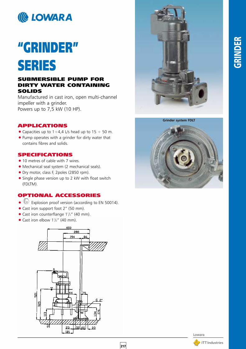
217
GRIN
DER
“GRINDER”SERIESSUBMERSIBLE PUMP FORDIRTY WATER CONTAININGSOLIDSManufactured in cast iron, open multi-channelimpeller with a grinder.Powers up to 7,5 kW (10 HP).
Grinder system FDLT
APPLICATIONS•Capacities up to 1÷4,4 L/s head up to 15 ÷ 50 m.
•Pump operates with a grinder for dirty water thatcontains fibres and solids.
SPECIFICATIONS•10 metres of cable with 7 wires.
•Mechanical seal system (2 mechanical seals).
•Dry motor, class F, 2poles (2850 rpm).
•Single phase version up to 2 kW with float switch(FDLTM).
OPTIONAL ACCESSORIES
• Explosion proof version (according to EN 50014).
•Cast iron support foot 2” (50 mm).
•Cast iron counterflange 11/2” (40 mm).
•Cast iron elbow 11/2” (40 mm).

218
GRIN
DER
1 0,8 2,3 3ph 400V- 50 Hz 2850 6 33
2 1,1 2,5 3ph 400V- 50 Hz 2850 6 33
3 1,4 2,9 3ph 400V- 50 Hz 2850 6 34
4 1,5 3 3ph 400V- 50 Hz 2850 6 34
5 2 3,8 3ph 400V- 50 Hz 2850 6 34
6 2,5 4,5 3ph 400V- 50 Hz 2850 7 45
7 3,2 5,5 3ph 400V- 50 Hz 2850 7 45
8 3,8 7 3ph 400-690 V- 50 Hz 2850 7 60
9 4,2 7,5 3ph 400-690 V- 50 Hz 2850 7 60
10 4,9 8,6 3ph 400-690 V- 50 Hz 2850 7 60
FDLT 41-23 40 S-R
FDLT 41-22 40 S-R
FDLT 41-21 40 S-R
FDLT 42-22 40 S-R
FDLT 42-21 40 S-R
FDLT 43-22 40 S-R
FDLT 43-21 40 S-R
FDLT 44-22 40 S-R
FDLT 44-21 40 S-R
FDLT 45-21 40 S-R
SUBMERSIBLE ELECTRIC PUMPS GRINDER, 1’’1/2, R.P.M. 2850
Construction in CAST IRON G250 UNI ISO 185
CAPACITYQ(m /h)
3
Q(l/s)
H(m)
TOTALHEAD
0
5
10
15
20
25
30
35
40
45
50
0 1 2 3 4 5
0 2 4 6 8 10 12 14 16 18
FDLT 41/42
FDLT 43/45
Curve Pump Type Input Power Nom.Current Power Supply Rotation Speed Free Passage Outlet Diameter Weight Installation
N° kW A R.P.M. mm mm Kg
Grinder
1
2
3
4
5
6
7
8
9
10
1 0,8 3,7 1ph 230V- 50 Hz 2850 6 33
2 1,1 4,5 1ph 230V- 50 Hz 2850 6 34
3 1,4 6,3 1ph 230V- 50 Hz 2850 6 34
4 1,5 7,1 1ph 230V- 50 Hz 2850 6 34
5 2 9,1 1ph 230V- 50 Hz 2850 6 34
FDLMT 41-23 40 S-R
FDLMT 41-22 40 S-R
FDLMT 41-21 40 S-R
FDLMT 42-22 40 S-R
FDLMT 42-21 40 S-R
Note:S: Fixing kitR: Lowering device with sliding guides
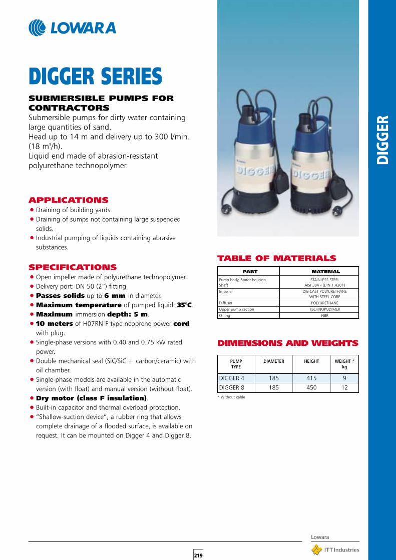
219
DIGG
ER
TABLE OF MATERIALS
APPLICATIONS•Draining of building yards.
•Draining of sumps not containing large suspendedsolids.
•Industrial pumping of liquids containing abrasivesubstances.
SPECIFICATIONS•Open impeller made of polyurethane technopolymer.
•Delivery port: DN 50 (2”) fitting
•Passes solids up to 6 mm in diameter.
•Maximum temperature of pumped liquid: 35°C.
•Maximum immersion depth: 5 m.
•10 meters of H07RN-F type neoprene power cordwith plug.
•Single-phase versions with 0.40 and 0.75 kW ratedpower.
•Double mechanical seal (SiC/SiC + carbon/ceramic) withoil chamber.
•Single-phase models are available in the automaticversion (with float) and manual version (without float).
•Dry motor (class F insulation).
•Built-in capacitor and thermal overload protection.
•“Shallow-suction device”, a rubber ring that allowscomplete drainage of a flooded surface, is available onrequest. It can be mounted on Digger 4 and Digger 8.
DIGGER SERIESSUBMERSIBLE PUMPS FORCONTRACTORSSubmersible pumps for dirty water containinglarge quantities of sand.Head up to 14 m and delivery up to 300 l/min.(18 m3/h).Liquid end made of abrasion-resistantpolyurethane technopolymer.
PART MATERIAL
Pump body, Stator housing, STAINLESS STEELShaft AISI 304 - (DIN 1.4301)
Impeller DIE-CAST POLYURETHANEWITH STEEL CORE
Diffuser POLYURETHANE
Upper pump section TECHNOPOLYMER
O-ring NBR
DIMENSIONS AND WEIGHTS
PUMP DIAMETER HEIGHT WEIGHT *TYPE kg
DIGGER 4 185 415 9
DIGGER 8 185 450 12* Without cable
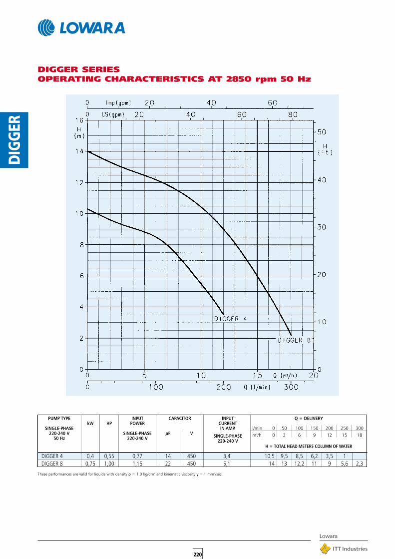
220
DIGG
ER
DIGGER 4 0,4 0,55 0,77 14 450 3,4 10,5 9,5 8,5 6,2 3,5 1DIGGER 8 0,75 1,00 1,15 22 450 5,1 14 13 12,2 11 9 5,6 2,3
DIGGER SERIESOPERATING CHARACTERISTICS AT 2850 rpm 50 Hz
PUMP TYPE INPUT CAPACITOR INPUTkW HP POWER CURRENT
SINGLE-PHASE IN AMP.220-240 V SINGLE-PHASE µF V SINGLE-PHASE50 Hz 220-240 V 220-240 V
Q = DELIVERY
l/min 0 50 100 150 200 250 300m3/h 0 3 6 9 12 15 18
H = TOTAL HEAD METERS COLUMN OF WATER
These performances are valid for liquids with density ρ = 1.0 kg/dm3 and kinematic viscosity γ = 1 mm2/sec.

QSM02 0,25 0,33 2,8 12,5 450QSM03 0,37 0,5 3,6 16 450QSM05 0,55 0,75 5 20 450 80 x 210 x 65 0,43 GS 4OSQSM07 0,75 1 6,3 30 450QSM11 1,1 1,5 9,2 40 450
221
CO
NTR
OL
PAN
ELS
QSM SERIESSINGLE-PHASEELECTRIC PANEL
ApplicationsProtection and control of a 4" single-phaseborehole pump.
SPECIFICATIONS•Main switch for manual control.
•Supply voltage: 1 x 220-230 V ±5%.
•Frequency: 50 Hz.
•Power: 0.25 to 1.1 kW.
•Direct motor start.
•Protection class: IP 44.
•Ambient temperature: -5 to +40 °C (limit specified byEN standard 60439-1).
•Maximum relative humidity: 50% at +40°C, providedthat no condensation occurs (limit specified by ENstandard 60439-1).
•Wall mounted.
•Plastic enclosure.
•Incorporated capacitor.
•Double-pole main switch.
•Thermal protector inside panel.
SPECIAL VERSIONS AVAILABLEON REQUEST
•QSM PF version with overvoltage protection (lightningprotector)
•QSM SP version without thermal protector inside panelfor Scuba series pumps, featuring incorporatedprotector only for 0.55, 0.9 and 1.1 kW versions.
PANEL TYPE RATED RATED CAPACITOR DIMENSIONS WEIGHT COMPATIBLE COMPATIBLEPOWER CURRENT A x B x C WITH PUMPS MOTORS
PACKING
kW HP A µF V mm kg
Line protection to be provided by user.

QPC 02 0,25 0,33 3 12,5 450QPC 03 0,37 0,5 4 16 450QPC 05 0,55 0,75 5 20 450QPC 07 0,75 1 6 30 450 200 x 150 x 80 1,1 GS
4OS
QPC 11 1,1 1,5 9 40 450F4
QPC 15 1,5 2 11 50 450QPC 22 2,2 3 16 70 450
222
CO
NTR
OL
PAN
ELS
QPC SERIESSINGLE-PHASE ELECTRICPANEL
ApplicationsProtection and control of a 4" single-phaseborehole pump.
SPECIFICATIONS•Main switch for manual control.•Supply voltage: 1 x 220-230 V ±5%.•Frequency: 50 Hz.•Power: 0.25 to 2.2 kW.•Direct motor start.•Protection class: IP 54.•Ambient temperature: -5 to +40 °C (limit specified by
EN standard 60439-1).•Maximum relative humidity: 50% at +40°C, provided
that no condensation occurs (limit specified by ENstandard 60439-1).
•Wall mounted using brackets provided.•Plastic enclosure•Incorporated capacitor•Main switch with thermal protector (manual reset) and
power ON indicator light
OPTIONAL ACCESSORIES•109890770 109890770 DPF single-phase module
for overvoltage protection (lightningprotector)
PANEL TYPE RATED RATED CAPACITOR DIMENSIONS WEIGHT COMPATIBLE COMPATIBLEPOWER CURRENT A x B x C WITH PUMPS MOTORS
PACKING
kW HP A µF V mm kg
Line protection to be provided by user.

QPCS 02 0,25 0,33 3 12,5 450QPCS 03 0,37 0,5 4 16 450QPCS 05 0,55 0,75 5 20 450QPCS 07 0,75 1 6 30 450 200 x 150 x 80 1,3 GS
4OS
QPCS 11 1,1 1,5 9 40 450F4
QPCS 15 1,5 2 11 50 450QPCS 22 2,2 3 16 70 450
223
CO
NTR
OL
PAN
ELS
QPCS SERIESSINGLE-PHASEELECTRIC PANEL
ApplicationsProtection and control of a 4" single-phaseborehole pump.
SPECIFICATIONS•Automatic control through an external contactor.•Supply voltage: 1 x 220-230 V ±5 %.•Frequency: 50 Hz.•Power: 0.25 to 2.2 kW.•12 Vac low voltage auxiliary circuit.•Direct motor start.•Protection class: IP 54.•Ambient temperature: -5 to +40 °C (limit specified by
EN standard 60439-1).•Maximum relative humidity: 50% at +40°C, provided
that no condensation occurs (limit specified by ENstandard 60439-1).
•Wall mounted using the brackets provided.•Plastic enclosure with see-through cover•Capacitor (incorporated) •Main switch with thermal protector (manual reset) and
power ON indicator light•Power, pump running and dry running indicator LEDs.•Overvoltage protection.•Dry running control through probes, float or minimum
pressure switch.
OPTIONAL ACCESSORIES•Kit n. 3 electrodes (probes) without cable, code
RLE901400•Float•Pressure switch
PANEL TYPE RATED RATED CAPACITOR DIMENSIONS WEIGHT COMPATIBLE COMPATIBLEPOWER CURRENT A x B x C WITH PUMPS MOTORS
PACKING
kW HP A µF V mm kg
Line protection to be provided by user.

QMC/02 0,25 0,33 3 12,5 450QMC/03 0,37 0,5 4 16 450QMC/05 0,55 0,75 5 20 450QMC/07 0,75 1 6 30 450 170 x 200 x 105 2,5 GS
4OS
QMC/11 1,1 1,5 9 40 450F4
QMC/15 1,5 2 11 50 450QMC/22 2,2 3 16 70 450 235 x 265 x 150
224
CO
NTR
OL
PAN
ELS
QMC SERIESSINGLE-PHASEELECTRIC PANEL
ApplicationsProtection and control of a 4" single-phaseborehole pump.
SPECIFICATIONS•Main switch for manual control.•Supply voltage: 1 x 220-230 V ±5%.•Frequency: 50 Hz.•Power: 0.25 to 2.2 kW.•Direct motor start.•Protection class: IP 54.•Ambient temperature: -5 to +40 °C (limit specified by
EN standard 60439-1).•Maximum relative humidity: 50% at +40°C, provided
that no condensation occurs (limit specified by ENstandard 60439-1).
•Wall mounted.•Metal enclosure•Capacitor (incorporated) •Main switch with thermal protector (manual reset) and
power ON indicator light
OPTIONAL ACCESSORIES•109890770 DPF single-phase module for overvoltage
protection (lightning protector)
PANEL TYPE RATED RATED CAPACITOR DIMENSIONS WEIGHT COMPATIBLE COMPATIBLEPOWER CURRENT A x B x C WITH PUMPS MOTORS
PACKING
kW HP A µF V mm kg
Line protection to be provided by user.

QMCSS/02 0,25 0,33 3 12,5 450QMCS/03 0,37 0,5 4 16 450QMCS/05 0,55 0,75 5 20 450QMCS/07 0,75 1 6 30 450 235 x 265 x 150 4 GS 4OSQMCS/11 1,1 1,5 9 40 450 F4QMCS/15 1,5 2 11 50 450QMCS/22 2,2 3 16 70 450 250 x 320 x 150
225
CO
NTR
OL
PAN
ELS
QMCS SERIESSINGLE-PHASEELECTRIC PANEL
ApplicationsProtection and control of a 4" single-phaseborehole pump.
SPECIFICATIONS•Automatic control through an external contactor.•Supply voltage: 1 x 220-230 V ±5 %.•Frequency: 50 Hz.•Power: 0.25 to 2.2 kW.•Direct motor start.•Protection class: IP 54.•Ambient temperature: -5 to +40 °C (limit specified by
EN standard 60439-1).•Maximum relative humidity: 50% at +40°C, provided
that no condensation occurs (limit specified by ENstandard 60439-1).
•Wall mounted.•Metal enclosure•Capacitor (incorporated) •Main switch with thermal protector (manual reset) and
power ON indicator light•Dry running control through probe, float or minimum
pressure switch (to be ordered separately).
OPTIONAL ACCESSORIES•109890770 DPF single-phase module for overvoltage
protection (lightning protector)•109890690 SLD series 24V level kit Probe module for
protection against dry running (set of three electrodes included in the supply)
PANEL TYPE RATED RATED CAPACITOR DIMENSIONS WEIGHT COMPATIBLE COMPATIBLEPOWER CURRENT A x B x C WITH PUMPS MOTORS
PACKING
kW HP A µF V mm kg
Line protection to be provided by user.

QM/02 0,25 0,33 1.4-2.3 BG LQQM/03 0,37 0,5 2.0-3.3 HM FHQM/05 0,55 0,75 3.0-5.0
235x265x150 5,8HMS SH
QM/07 0,75 1 4.5-7.5 CAM SVQM/11 1,1 1,5 6.0-10.0 CEAM SVIQM/22 2,2 3 9.0-15.0 COM
226
CO
NTR
OL
PAN
ELS
QM SERIESSINGLE-PHASEELECTRIC PANEL
ApplicationsProtection and control of a single-phasesurface pump.
SPECIFICATIONS•Control through an external contactor.•Supply voltage: 1 x 230 V ±5 %.•Frequency: 50/60 Hz.•Power: 0.25 to 2.2 kW.•Direct motor start.•Protection class: IP 54.•Ambient temperature: -5 to +40 °C (limit specified by
EN standard 60439-1).•Maximum relative humidity: 50% at +40°C, provided
that no condensation occurs (limit specified by ENstandard 60439-1).
•Wall mounted•Metal enclosure•Ready for installation of dry running control float or
pressure switch (to be ordered separately)•Power and thermal overload indicator lights
OPTIONAL ACCESSORIES•109890740 VR1 single-phase varistor module
overvoltage protection (lightningprotector)
•109890690 SLD series 24V level kitProbe module for protection against dryrunning (set of three electrodes includedin the supply)
PANEL TYPE RATED APPLICATION DIMENSIONS WEIGHT COMPATIBLEPOWER RANGE A x B x C WITH PUMPS
PACKING
kW HP A kg SURFACE
Line protection to be provided by user.
For proper selection, make sure that the ampere input of the electric motor falls within the application range shown in the table.

QTD/03 0,37 0,5 0.9-1.5 BG SCUBA 4OSQTD/05 0,55 0,75 1.4-2.3 HM,HMS GS OS6QTD/11 1,1 1,5 2.0-3.3 CA,CEA OZ F4QTD/15 1,5 2 3.0-5.0 CO, LQ FZ F6QTD/22 2,2 3 4.5-7.5 235x265x150 5,8 FH TVQTD/30 3 4 6.0-10.0 SHQTD/40 4 5,5 9.0-12.0 SVIQTD/55 5,5 7,5 9.0-15.0 SVIQTD/92 9,2 12,5 14.0-23.0 SFC
227
CO
NTR
OL
PAN
ELS
QTD SERIESTHREE-PHASE ELECTRICPANEL
ApplicationsProtection and control of a three-phasesurface or borehole pump.
SPECIFICATIONS•Control through an external enable contact•Supply voltage: 3 x 400 V ±10 %.•Frequency: 50/60 Hz.•Power: 0.37 to 9.2 kW.•Direct motor start.•Protection class: IP 54.•Ambient temperature: -5 to +40 °C (limit specified by
EN standard 60439-1).•Maximum relative humidity: 50% at +40°C, provided
that no condensation occurs (limit specified by ENstandard 60439-1).
•Wall mounted•Metal enclosure•Ready for installation of dry running control float or
pressure switch (to be ordered separately)•Power and thermal overload indicator lights
OPTIONAL ACCESSORIES•109890760 VR3 three-phase module for overvoltage
protection (lightning protector)•109890690 SLD series 24V level kit
Probe module for protection against dryrunning (set of three electrodes includedin the supply)
PANEL TYPE RATED APPLICATION DIMENSIONS WEIGHT COMPATIBLE COMPATIBLEPOWER RANGE A x B x C WITH PUMPS MOTORS
PACKING
kW HP A mm kg SURFACE BOREHOLE
Line protection to be provided by user.
For proper selection, make sure that the ampere input of the electric motor falls within the application range shown in the table.

Q3D/03 0,37 0,5 0,9-1,5 Q3D/05 0,5 0,75 1,4-2,3 Q3D/11 1,1 1,5 2,0-3,3 Q3D/15 1,5 2,0 3,0-5,0 Q3D/22 2,2 3,0 4,5-7,5 400 x 500 x 200Q3D/30 3 4,0 6,0-10,0 Q3D/40 4 5,5 9,0-12,0 40Q3D/55 5,5 7,5 9,0-15,0 Q3D/92 9,2 12,5 14,0-23,0 Q3D/110 11 15 20,0-32,0 Q3D/150 15 20 28,0-38,0 Q3D/220 22 30 35,0-50,0 Q3D/300 30 40 45,0-63,0 400 x 600 x 200 50Q3D/370 37 50 60,0-80,0
228
CO
NTR
OL
PAN
ELS
Q3D SERIESTHREE-PHASE ELECTRIC PANELApplicationsProtection and control of a three-phasesurface or borehole pump.
SPECIFICATIONS•Manual control through Auto/Man selector switch. •Automatic control through an external enable contact. •Supply voltage: 3 x 400 V ±10 %. Frequency: 50/60 Hz. •24 Vac low voltage auxiliary circuit. •Power: 0.37 to 37 kW. •Direct start. •Protection class: IP 54. •Ambient temperature: -5 to +40 °C (limit specified by
EN standard 60439-1). •Maximum relative humidity: 50% at +40°C, provided
that no condensation occurs (limit specified by ENstandard 60439-1).
•Wall mounted. •Metal enclosure. •Power - pump running - thermal overload - dry running
indicator lights. •Manual-reset thermal relay for overload protection,
sensitive to phase failure. •Ready for installation of dry running control float or
pressure switch (to be ordered separately). Can be fitted with electronic protection module withelectrodes.
OPTIONAL ACCESSORIES•109890690 SLD series 24V level kit
Probe module for protection against dryrunning (set of three electrodes includedin the supply)
•Float. •Pressure switch. •SCA3 (109890780) electronic module kit for overvoltage
protection of three-phase line (lightning protector).
PANRL TYPE RATED APPLICATION DIMENSIONS WEIGHT COMPATIBLE COMPATIBLEPOWER RANGE A x B x C WITH PUMPS MOTORS
PACKING
kW HP A Kg SURFACE BOREHOLE
Line protection to be provided by user.
For proper selection, make sure that the ampere input of the electric motor falls within the application range shown in the table.
BGHM, HMSCA, CEACO, LQ
FHSHSVISVISFC
SCUBAGSOZFZTV
4OSOS6F4F6

Q3Y/40 4 5,5 8,0-12,0Q3Y/55 5,5 7,5 11,0-16,0Q3Y/92 7,5 - 9,2 10 - 12,5 16,0-24,0 400 x 600 x 250 45Q3Y/110 11 15 24,0-32,0Q3Y/150 15 20 30,0-40,0Q3Y/220 18,5 - 22 25 - 30 35,0-50,0 500 x 700 x 250 50Q3Y/300 30 40 50,0-62,0
600 x 900 x 250 60Q3Y/370 37 50 60,0-80,0Q3Y/550 45 - 55 60 - 75 80,0-110,0
600 x 1300 x 300 floor 80/100Q3Y/750 75 100 90,0-140,0Q3Y/900 90 125 135,0-180,0
600 x 1500 x 300 floor 100/120Q3Y/1100 110 150 180,0-250,0
229
CO
NTR
OL
PAN
ELS
Q3Y SERIESTHREE-PHASE ELECTRIC PANELApplicationsProtection and control of a three-phase surfacepump.
SPECIFICATIONS•Manual control through Auto/Man selector switch.•Automatic control through an external enable contact.•Supply voltage: 3 x 400 V ±10 %. Frequency: 50/60 Hz.•24 Vac low voltage auxiliary circuit.•Power: 4 to 110 kW.•Star-delta starting.•Protection class: IP 54.•Ambient temperature: -5 to +40 °C (limit specified by
EN standard 60439-1).•Maximum relative humidity: 50% at +40°C, provided
that no condensation occurs (limit specified by ENstandard 60439-1).
•Wall mounted.•Metal enclosure.•Power - pump running - thermal overload - dry running
indicator lights.•Manual-reset thermal relay for overload protection,
sensitive to phase failure.•Ready for installation of dry running control float or
pressure switch (to be ordered separately).Can be fitted with electronic protection module withelectrodes.
OPTIONAL ACCESSORIES•109890690 SLD series 24V level kit
Probe module for protection against dryrunning (set of three electrodes includedin the supply)
•Float.•Pressure switch.•SCA3 (109890780) electronic module kit for overvoltage
protection of three-phase line (lightning protector).
Line protection to be provided by user.
For proper selection, make sure that the ampere input of the electric motor falls within the application range shown in the table.
PANEL TYPE RATED APPLICATION DIMENSIONS WEIGHT COMPATIBLEPOWER RANGE A x B x C WITH PUMPS
PACKING
kW HP A mm kg SURFACE BOREHOLE
FHSHSVSFC
Specify doublecable outlet for all
three-phaseversions

Q3I/55 5,5 7,5 9,0-15,0 400 x 600 x 250 50Q3I/92 7,5 - 9,2 10 - 12,5 14,0-23,0
Q3I/110 11 15 20,0-32,0 Q3I/150 12,5 - 15 17 - 20 28,0-38,0 500 x 700 x 250 70Q3I/220 18,5 - 22 25 - 30 35,0-47,0 Q3I/300 30 40 46,0-62,0
600 x 900 x 250 90Q3I/370 37 50 60,0-78,0 Q3I/550 45 - 55 60 - 75 75,0-110,0Q3I/750 75 100 90,0-140,0
600 x 1300 x 300 floor100/150Q3I/900 90 125 120,0-180,0
Q3I/1100 110 150 180,0-250,0600 x 1500 x 300 floor
230
CO
NTR
OL
PAN
ELS
Q3I SERIESTHREE-PHASE ELECTRIC PANELApplicationsProtection and control of a three-phasesurface or borehole pump.
SPECIFICATIONS•Manual control through Auto/Man selector switch.•Automatic control through an external enable contact.•Supply voltage: 3x400 V ±10 %. Frequency: 50/60 Hz.•24 Vac low voltage auxiliary circuit.•Power: 5.5 to 110 kW.•Impedance start.•Protection class: IP 54.•Ambient temperature: -5 to +40 °C (limit specified by
EN standard 60439-1).•Maximum relative humidity: 50% at +40°C, provided
that no condensation occurs (limit specified by ENstandard 60439-1).
•Wall mounted.•Metal enclosure.•Power - pump running - thermal overload - dry running
indicator lights.•Manual-reset thermal relay for overload protection,
sensitive to phase failure.•Ready for installation of dry running control float or
pressure switch (to be ordered separately).Can be fitted with electronic protection module withelectrodes.
OPTIONAL ACCESSORIES•109890690 SLD series 24V level kit
Probe module for protection against dryrunning (set of three electrodes included
in the supply)•Float.•Pressure switch.•SCA3 (109890780) electronic module kit for overvoltage
protection of three-phase line (lightning protector).
PANEL TYPE RATED APPLICATION DIMENSIONS WEIGHT COMPATIBLE COMPATIBLEPOWER RANGE A x B x C WITH PUMPS MOTORS
PACKING
kW HP A kg SURFACE BOREHOLE
Line protection to be provided by user.
For proper selection, make sure that the ampere input of the electric motor falls within the application range shown in the table.
FH GS 4OSSH OZ F4SV FZ F6SFC TV

Q3A/55 5,5 7,5 9,0-15,0 Q3A/92 7,5 - 9,2 10 - 12,5 14,0-23,0 Q3A/110 11 15 20,0-32,0
500 x 700 x 250 50
Q3A/150 12,5 - 15 17 - 20 28,0-38,0 Q3A/220 18,5 - 22 25 - 30 35,0-47,0 600 x 900 x 300Q3A/300 30 40 46,0-62,0
600 x 1300 x 300 floor80
Q3A/370 37 50 60,0-78,0 Q3A/550 45 - 55 60 - 75 75,0-110,0
600 x 1500 x 300 floorQ3A/750 75 100 90,0-140,0100/150Q3A/900 90 125 120,0-180,0
600 x 1700 x 400 floorQ3A/1100 110 150 180,0-250,0
231
CO
NTR
OL
PAN
ELS
Q3A SERIESTHREE-PHASE ELECTRIC PANELApplicationsProtection and control of a three-phasesurface or borehole pump.
SPECIFICATIONS•Manual control through Auto/Man selector switch.•Automatic control through an external enable contact.•Supply voltage: 3 x 400 V ±10 %. Frequency 50/60 Hz.•24 Vac low voltage auxiliary circuit.•Power: 5.5 to 110 kW.•Autotransformer start.•Protection class: IP 54.•Ambient temperature: -5 to +40 °C (limit specified by
EN standard 60439-1).•Maximum relative humidity: 50% at +40°C, provided
that no condensation occurs (limit specified by ENstandard 60439-1).
•Wall mounted.•Metal enclosure.•Power - pump running - thermal overload - dry running
indicator lights.•Manual-reset thermal relay for overload protection,
sensitive to phase failure.•Ready for installation of dry running control float or
pressure switch (to be ordered separately).Can be fitted with electronic protection module withelectrodes.
OPTIONAL ACCESSORIES•109890690 SLD series 24V level kit
Probe module for protection against dryrunning (set of three electrodes includedin the supply)
•Float.•Pressure switch.•SCA3 (109890780) electronic module kit for•vervoltage protection of three-phase line (lightning
protector).
PANEL TYPE RATED APPLICATION DIMENSIONS WEIGHT COMPATIBLE COMPATIBLEPOWER RANGE A x B x C WITH PUMPS MOTORS
PACKING
kW HP A kg SURFACE BOREHOLE
Line protection to be provided by user.
For proper selection, make sure that the ampere input of the electric motor falls within the application range shown in the table.
FH GS 4OSSH OZ F4SV FZ F6SFC TV

Line protection to be provided by user.
For proper selection, make sure that the ampere input of the electric motor falls within the application range shown in the table.
Q3SF/75 5,5-7,5 7,5-10 8,5-17Q3SF/150 9,2-15 12,5-20 15-30 500 x 700 x 250 70Q3SF/220 18,5-22 25-30 28-45Q3SF/300 30 40 42-60Q3SF/370 37 50 55-75Q3SF/450 45 60 70-85 600 x 900 x 300 90Q3SF/550 55 75 80-110Q3SF/590 59 80 105-125Q3SF/750 75 100 120-142
600 x 1700 x 400Q3SF/900 90 122 135-190pavimento
120Q3SF/1100 110 150 185-245
232
CO
NTR
OL
PAN
ELS
Q3SF SERIESTHREE-PHASE ELECTRIC PANEL
ApplicationsProtection and control of a three-phasesurface or borehole pump.
SPECIFICATIONS•Manual control through Auto/Man selector switch. •Automatic control through an external enable contact. •Supply voltage: 3x400 V ±10 %. Frequency 50/60 Hz. •24 Vac low voltage auxiliary circuit. •Power: 5.5 to 110 kW. •Soft start with torque control. •Protection class: IP 54. •Ambient temperature: -5 to +40 °C (limit specified by
EN standard 60439-1). •Maximum relative humidity: 50% at +40°C, provided
that no condensation occurs (limit specified by ENstandard 60439-1).
•Wall mounted. •Metal enclosure. •Dry running indicator light. •Power-running-failure indicator LEDs on starter keypanel. •0-1 selector switch for activation of bypass contactor. •Ready for installation of dry running control float or
pressure switch (to be ordered separately).Can be fitted with electronic protection module withelectrodes.
STATIC STARTERCHARACTERISTICS •Static starter for gradual starting and stopping, featuring:
keypanel with liquid crystal display, showing the followingvalues: voltage, current input, cos �, operating hours,umber of starts, last twenty messages regarding systemstatus (events / alarms).Phase failure - phase sequence - out of range frequencyprotections on power supply line.Low voltage protection on auxiliary circuits.Overheating - overload - malfunction protections onstarter.Overload - jammed rotor - current asymmetry protectionson motor side.Short circuit protections on inputs and outputs.RS232 interface for remote control and RS485 for use ofremote keypanel.Incorporated bypass contactor.
PANEL TYPE RATED APPLICATION DIMENSIONS WEIGHT COMPATIBLE COMPATIBLEPOWER RANGE A x B x C WITH PUMPS MOTORS
PACKING
kW HP A mm kg SURFACE BOREHOLE
OPTIONAL ACCESSORIES•109890690 SLD series 24V level kit
Probe module for protectionagainst dry running (set ofthree electrodes included in thesupply)
•Float. •Pressure switch. •SCA3 (109890780) electronic module kit for
overvoltage protection of three-phase line(lightning protector).
FH OZSH FZ
F6SV TVSFC

233
CO
NTR
OL
PAN
ELS
QDRM SERIES single-phase
QDR SERIES three-phaseELECTRICAL PANEL FORDRAINAGE PUMPSApplicationsProtection and control of a single- or three-phasedrainage pump.
SPECIFICATIONS•Automatic control through electromechanical floats
•Supply voltage: 1 x 230 V ±10 % (single-phase)3 x 400 V ± 10% (three-phase)
•Frequency: 50/60 Hz.
•Power: 0.25 to 2.2 kW for single-phase version.
•Power: 0.37 to 9.2 KW for three-phase version.
•Direct motor start.
•Protection class: IP 54.
•Ambient temperature: -5 to +40 °C (limit specified byEN standard 60439-1).
•Maximum relative humidity: 50% at +40°C, providedthat no condensation occurs (limit specified by ENstandard 60439-1).
•Wall mounted
•Metal enclosure
•Power, thermal overload, high level indicator lights.
OPTIONAL ACCESSORIES•Audible or visual signalling device, 12 VDC 0.5 A max
(inside the electric panel there is a connection terminal)for high-level alarm.109890740 VR1 single-phase module (for QDRM) forovervoltage protection (lightning protector) 109890760VR3 three-phase module (for QDR) for overvoltageprotection (lightning protector).

QDR/03 0,37 0,5 0,9-1,5 DOCQDR/05 0,55 0,75 1,4-2,3 DIWAQDR/11 1,1 1,5 2,0-3,3 DNQDR/15 1,5 2 3,0-5,0 DOMOQDR/22 2,2 3 4,5-7,5 235x265x150 6,3 DLQDR/30 3 4 6,0-10,0 FDL*QDR/40 4 5,5 9,0-12,0 FXDL*QDR/55 5,5 7,5 9,0-15,0 FBDL*QDR/92 9,2 12,5 14,0-23,0
QDRM/02 0,25 0,33 1,4-2,3 All the pumps that are equippedQDRM/03 0,37 0,5 2,0-3,3 with a capacitor (incorporated)QDRM/05 0,55 0,75 3,0-5,0
235x265x150 6,3or with one that is integrated in an
QDRM/07 0,75 1 4,5-7,5 external container can be suppliedQDRM/11 1,1 1,5 6,0-10,0 without pre-assembled float.QDRM/22 2,2 3 9,0-15,0
234
CO
NTR
OL
PAN
ELS
TANEL TYPE RATED APPLICATION DIMENSIONS WEIGHT COMPATIBLEPOWER RANGE A x B x C WITH PUMPS
PACKING
kW HP A kg DRAINAGE
TANEL TYPE RATED APPLICATION DIMENSIONS WEIGHT COMPATIBLEPOWER RANGE A x B x C WITH PUMPS
PACKING
kW HP A kg DRAINAGE
Line protection to be provided by user.
* Electric pump without thermal stator protection or water control probe in oil bath.
For proper selection, make sure that the ampere input of the electric motor falls within the application range shown in the table.

235
CO
NTR
OL
PAN
ELS
9QDRM2 SERIES single-phase
9QDR2 SERIES three-phaseELECTRICAL PANEL FORDRAINAGE PUMPSApplicationsProtection and control of two single- orthree-phase drainage pumps.
SPECIFICATIONS•Automatic control through electromechanical floats
•Supply voltage: 1 x 230 V ±10 % (single-phase)3 x 400 V ± 10% (three-phase)
•Frequency: 50/60 Hz.
•Power: 0.25 to 2.2 kW for single-phase version.
•Power: 0.37 to 9.2 KW for three-phase version.
•Direct motor start.
•Protection class: IP 54.
•Ambient temperature: -5 to +40 °C (limit specified byEN standard 60439-1).
•Maximum relative humidity: 50% at +40°C, providedthat no condensation occurs (limit specified by ENstandard 60439-1).
•Wall mounted
•Metal enclosure.
•Electronic board with power, overload, high-level alarm,pump on/off indicator LEDs.
OPTIONAL ACCESSORIES•Audible or visual signalling device, 12 VDC 0.3 A max
(inside the electric panel there are two connectionterminals) for high-level alarm.109890740 VR1 single-phase module (for 9QDRM2) forovervoltage protection (lightning protector) 109890760VR3 three-phase module (for 9QDR2) for overvoltageprotection (lightning protector) 109391130 signal relayboard kit (power, auto/man, on/off, overload, highlevel).

9QDR2/03 0,37 0,5 0,63-1,0 DOC9QDR2/05 0,55 0,75 1,0-1,6 DIWA9QDR2/11 1,1 1,5 1,6-2,5 DN9QDR2/15 1,5 2 2,5-4,0 DOMO9QDR2/22 2,2 3 4,0-6,5 260x380x150 9,4 DL9QDR2/30 3 4 6,3-10,0 FDL*9QDR2/40 4 5,5 9,014,0 FXDL*9QDR2/55 5,5 7,5 13,0-18,0 FBDL*9QDR2/92 9,2 12,5 17,0-23,0 300x400x180
9QDRM2/02 0,25 0,33 1,0-1,6 All the pumps that are equipped9QDRM2/03 0,37 0,5 1,6-2,5 with a capacitor (incorporated)9QDRM2/05 0,55 0,75 2,5-4,0
260x380x150 9,4or with one that is integrated in an
9QDRM2/07 0,75 1 4,0-6,5 external container can be supplied9QDRM2/11 1,1 1,5 6,3-10,0 without pre-assembled float.9QDRM2/22 2,2 3 9,0-14,0
236
CO
NTR
OL
PAN
ELS
PANEL TYPE RATED APPLICATION DIMENSIONS WEIGHT COMPATIBLEPOWER RANGE A x B x C WITH PUMPS
PACKING
kW HP A kg DRAINAGE
PANEL TYPE RATED APPLICATION DIMENSIONS WEIGHT COMPATIBLEPOWER RANGE A x B x C WITH PUMPS
PACKING
kW HP A kg DRAINAGE
Line protection to be provided by user.
* Electric pump without thermal stator protection or water control probe in oil bath.
For proper selection, make sure that the ampere input of the electric motor falls within the application range shown in the table.

108328400 QCL5/230V 1x220-23050/60 Hz
no-c-nc 48 V a 3 A 90x130x60 0,5108328300 QCL5/24V 1x2450/60 Hz
0 50 0,5050 100 0,75
100 200 1,00200 400 2,50400 oltre 4,00
237
CO
NTR
OL
PAN
ELS
QCL5 SERIESLEVEL CONTROL PANEL
ApplicationsAccessory for electric pump control panels,suitable for tank filling or drainageapplications or for activation of audibleor visual alarms.
SPECIFICATIONS•Automatic control through probes.•Supply voltage: 1 x 230 V ±10 % or 1 x 24 V ± 10 %.•Frequency: 50/60 Hz.•Voltage to probes: 15 VAC at 0.5 mA max.•Switch contact: 48 VAC at 3 A max (250 W max).•Protection class: IP 55.•Ambient temperature: -5 to +40 °C (limit specified by
EN standard 60439-1).•Maximum relative humidity: 50% at +40°C, provided
that no condensation occurs (limit specified by ENstandard 60439-1).
•Wall mounted.•Electrodes suitable for water at a maximum temperature
of 40°C.•Plastic enclosure•Set of three electrodes included in the supply
OPTIONAL ACCESSORIES•Drop cable with circular cross section.
For connection of the electrodes to thepanel we recommend the followingcross sections:
LENGTH CABLE CROSS SECTION
mt mm2
Three-pole cables can be usedfor short lengths.Otherwise we recommend the use ofunipolar cables placed at suitabledistances from each other to preventthe capacitive effect of the cable frominterfering with the proper operationof the electronic module.
CODE PANEL VOLTAGE OUTPUT CONTACT DIMENSIONS WEIGHTTYPE CONTACTS CAPACITY A x B x C WITH
PACKINGV mm kg
Line protection to be provided by user.

108328700 QCL10/230V 1x220-230 – All single-phase pumps up to 9A50/60 Hz –
AC3 230 V a 9 A 190x140x80 1are equipped with an
108328600 QCL10/24V 1x220-230 1x24 incorporated capacitor50/60 Hz 50/60 Hz
0 50 0,5050 100 0,75100 200 1,00200 400 2,50400 oltre 4,00
238
CO
NTR
OL
PAN
ELS
SPECIFICATIONS•Automatic control through probes. •Supply voltage: 1 x 230 V ±10 % , or 1 x 230 V
± 10 % + 1 x 24V ± 10% •Frequency: 50/60 Hz. •Voltage to probes: 15 VAC at 0.5 mA max. •Protection class: IP 55. •Ambient temperature: -5 to +40 °C (limit specified by
EN standard 60439-1). •Maximum relative humidity: 50% at +40°C, provided
that no condensation occurs (limit specified by ENstandard 60439-1).
•Wall mounted. •Electrodes suitable for water at a maximum temperature
of 40°C. •Plastic casing. •Set of three electrodes included in the supply.
OPTIONAL ACCESSORIES•Drop cable with circular cross section.
SPECIAL VERSIONS AVAILABLEON REQUEST•Version with magnetothermal double-pole switch(QCLP10/)
For connection of the electrodes to the panelwe recommend the following cross sections:
Three-pole cables can be used for short lengths.Otherwise we recommend the use of unipolar cablesplaced at suitable distances from each other to prevent thecapacitive effect of the cable from interfering with theproper operation of the electronic module.
QCL10 SERIESLEVEL CONTROL PANELApplicationsAccessory for electric pump control panels,suitable for tank filling or drainageapplications or for activation of audibleor visual alarms. It can be used ascontrol panel for small electric pumps.
LENGTH CABLE CROSS SECTION
mt mm2
CODE PANEL VOLTAGE CONTACTOR CONTACT DIMENSIONS WEIGHT COMPATIBLETYPE CAPACITY A x B x C WITH PUMPS
Main Secondary PACKING
V V mm kg
Line protection to be provided by user.

108329000 QCLP10/230V 1x220-230 – All single-phase pumps up to 9A50/60 Hz –
AC3 230 V a 9 AC 10 A
195x200x112 1,5are equipped with an
108328900 QCPL10/24V 1x220-230 1x24 Icn 6 KA incorporated capacitor50/60 Hz 50/60 Hz
0 50 0,5050 100 0,75
100 200 1,00200 400 2,50400 oltre 4,00
239
CO
NTR
OL
PAN
ELS
SPECIFICATIONS•Automatic control through probes.•Supply voltage: 1 x 230 V ±10 % , or 1 x 230 V ±10 %
+ 1 x 24V ±10%•Frequency: 50/60 Hz.•Voltage to probes: 15 VAC at 0.5 mA max.•Protection class: IP 55.•Ambient temperature: -5 to +40 °C (limit specified by
EN standard 60439-1).•Maximum relative humidity: 50% at +40°C, provided
that no condensation occurs (limit specified by ENstandard 60439-1).
•Wall mounted.•Electrodes suitable for water at a maximum temperature
of 40°C.•Enclosure made of plastic material, with clear door
enabling access to the magnetothermal switch.•Set of three electrodes included in the supply.
OPTIONAL ACCESSORIES•Drop cable with circular cross section.
For connection of the electrodes to the panelwe recommend the following cross sections:
Three-pole cables can be used for short lengths.Otherwise we recommend the use of unipolar cablesplaced at suitable distances from each other to prevent thecapacitive effect of the cable from interfering with theproper operation of the electronic module.
QCLP10 SERIESLEVEL CONTROLPANELApplicationsAccessory for electric pump control panels,suitable for tank filling or drainageapplications or for activation of audibleor visual alarms. It can be used ascontrol panel for small electric pumps.
LENGTH CABLE CROSS SECTION
mt mm2
CODE PANEL VOLTAGE CONTACTOR CONTACT MAGNETO- DIMENSIONS WEIGHT COMPATIBLETYPE CAPACITY THERMAL A x B x C WITH PUMPS
Main Secondary SWITCH PACKING
V V mm kg
Line protection to be provided by user.

0 50 0,5050 100 0,75100 200 1,00200 400 2,50400 oltre 4,00
240
CO
NTR
OL
PAN
ELS
SPECIFICATIONS•Electronic module for probe utilisation as protection
against dry running.•Supply voltage: 1 x 24 V ± 10 % for model SLD/24.•Frequency: 50/60 Hz.•Absorbed power: 2 VA.•Voltage to probes: 15 VAC at 0.5 mA max.•Switch contact: 24 VAC at 5 A max (250 W max).•Designed for assembly on Lowara electric panels
featuring DIN bar.•Electrodes suitable for water at a maximum temperature
of 40°C.
CONSTRUCTIONCHARACTERISTICS•Module made of plastic material with DIN bar
attachment.•Cables with quick-coupling connectors.•Set of three electrodes included in the supply.•Electrodes with nylon 6 body, stainless steel sensitive
element, brass washer and nitrile rubber seal.
OPTIONAL ACCESSORIES•Drop cable with circular cross section.
SLD SERIESLEVEL PROBE MODULEApplicationsAccessory for electric panels.
For connection of the electrodes to thepanel we recommend the followingcross sections:
LENGTH CABLE CROSS SECTION
mt mm2
Three-pole cables can be usedfor short lengths.Otherwise we recommend the use ofunipolar cables placed at suitabledistances from each other to preventthe capacitive effect of the cable frominterfering with the proper operationof the electronic module.
CODE TYPE VOLTAGE CONTACT APPLICATIONS DIMENSIONSCAPACITY A x B x C
V mm
109890690 Kit SLD/24 1 x 24 24 V at 5 A QMCS-QM50/60 Hz QTD
Q3D-Q3Y 90 x 35 x 60Q2A-Q3I
Q3SF

109890740 KIT VR1 1 x 220-230 QDRM - 9QDRM2QM
109890760 KIT VR3 3 x 400 QTD - QDR50/60 Hz 9QDR2
241
CO
NTR
OL
PAN
ELS
DPF SERIESPROTECTION AGAINSTLIGHTNINGApplicationsAccessory for electric panels.
SPECIFICATIONS•Varistor for overvoltage protection of single-phase lines.
To be connected between phase and neutral wires.
•Operating voltage: 460 VAC.
•Maximum varistor voltage: 750 V with 100 A peakcurrent.
CODE TYPE VOLTAGE APPLICATION
V
109890770 DPF 1x220-240 QSM - QMC - QMCSQSMSP - QPC
SPECIFICATIONS•Lightning arresters for protection of three-phase lines.
To be connected between the phases and earthconductor.
•Operating voltage: 500 VAC.•Max varistor voltage: 2.5 kV with 40 kA peak current.•Designed for assembly on Lowara electric panels
featuring DIN bar.
CODE TYPE VOLTAGE APPLICATION
V
VR SERIES
SCA3 SERIESSPECIFICATIONS•Lightning arresters for protection of three-phase lines.
To be connected between the phases and earthconductor.
•Operating voltage: 500 VAC.•Max varistor voltage: 2.5 kV with 40 kA peak current.•Designed for assembly on Lowara electric panels
featuring DIN bar.
CODE TYPE VOLTAGE APPLICATION
V
109890780 KIT SCA3 3 x 400 Q3Y - Q3A - Q3I - Q3SF50/60 Hz Q3D
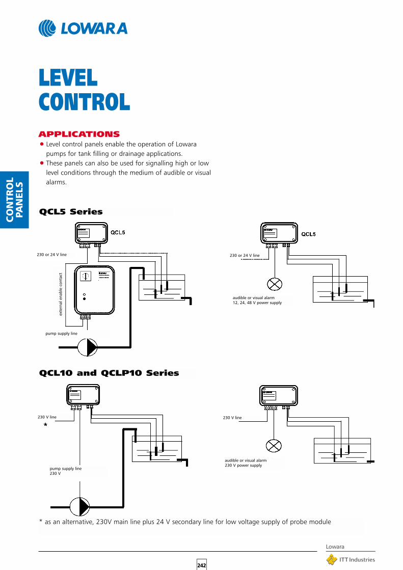
242
CO
NTR
OL
PAN
ELS
APPLICATIONS•Level control panels enable the operation of Lowara
pumps for tank filling or drainage applications.
•These panels can also be used for signalling high or lowlevel conditions through the medium of audible or visualalarms.
LEVELCONTROL
QCL5 Series
QCL10 and QCLP10 Series
* as an alternative, 230V main line plus 24 V secondary line for low voltage supply of probe module
230 or 24 V line
exte
rnal
ena
ble
cont
act
pump supply line
230 or 24 V line
audible or visual alarm12, 24, 48 V power supply
230 V line
pump supply line230 V
230 V line
audible or visual alarm230 V power supply

APPLICATIONS•Pressure regulation in the water systems of civil,
residential and industrial buildings.
•Handling of liquids in conditioning systems where it isnecessary to boost pressure in pipes with excessive flowresistance.
•Water treatment and process engineering for constantdelivery when pressure variations occur.
SPECIFICATIONS•Single phase models:Hydrovar HV 2/.. SeriesPower: 1.5 ÷ 2.2 kW.Mains voltage U: 1x230 V, ±10%, 50-60 HzMotor voltage U1: 3x230 V 50-60 Hz
•Three-phase models:Hydrovar HV 3/.. series Power: 2.2 ÷ 45 kW.Mains voltage U: 3x400 V, ±10%, 50-60 Hz.Motor voltage U1: 3x400 V 50-60 Hz.
•Ambient temperature from 5°C to 40°C.
•50% humidity at 40°C.
• IP 55 protection up to 11 kW.IP 54 protection for higher power.
•Built-in anti-condensate device.
•Designed to connect up to 4 Hydrovars.
•Individually interface with a computer through anRS485 system.
•Display with directions in 7 selectablelanguages.
243
HYDR
OVAR
HYDROVAR®
FREQUENCYCONVERTERSHydrovar® is a microprocessor based pumpingsystem controller that manages your pumpperformance to match a wide range of systemconditions and requirements.

THE TECHNOLOGYCONTROL AND REGULATION
•The HYDROVAR integrated frequency converter featuresautomatic regulation of the speed of an asynchronousthree-phase electric motor, by interpreting either a pres-sure or a differential pressure or a delivery signal (Fig. 1and 2).A patented control system disconnects the pump in caseof a decrease in user demand.
•The pump delivery is detected indirectly through thespeed, enabling the pressure, or the differential pres-sure, to be regulated according to the rate of consump-tion, based on the pre-set system characteristic parame-ters (Fig. 3).
•Besides the autonomous regulation possibilitiesdescribed above, the pump with the HYDROVAR devicecan also be connected to an external system on whichthe regulation parameters must be set.
•The HYDROVAR device is equipped with connection ter-minals for remote start and stop, for operating and fail-ure signals, and for the transmission of an analogue sig-nal (speed or actual value of the regulation signal) to acentral control station.It is also equipped with an RS 485 interface connectionfor communication with a central process control sys-tem.
•To prevent access and tampering by unauthorized per-sonnel, the set parameters can be partially or fully pro-tected by password. The activation or deactivation ofthe pump and the setting of the required parametersare obtained directly through the command keys, withmessages appearing on the frequency converter’s LCDdisplay.Three differently coloured diode indicator lights signal“ON”, “RUN” and “FAULT” (Fig. 4).Seven different languages can be selected for the infor-mation appearing on the display.
•In case of coupled systems, the microprocessor con-tained in each regulation unit automatically controls thepumps’ sequential operation based on system require-ments. It also controls their cyclic connection in seriesand automatic switch in case of malfunction, withoutrequiring any supplementary control devices.
•The frequency converter supplies a sinusoidal evaluationoutput voltage, modulated by impulse length. It oper-ates with controlled synthesis of the sinusoidal currentand dynamic current limitation. The high 8 kHz impulsefrequency prevents the development of undesired motornoise. With the harmonic filter any reactions in the lowvoltage areas are avoided (in compliance with EN 5501).The cooling of the frequency converter is ensured by thepump motor fan or, in the wall-mounted version, thefan located in its base.
244
HYDR
OVAR
REGULATION BASED ON CONSTANTPRESSURE.
Fig. 1
REGULATION BASED ON CONSTANTDELIVERY
Fig. 2
REGULATION BASED ON SYSTEM
CHARACTERISTICS
Fig. 3
Fig. 4

TYPE RATED INPUT VOLTAGE MOTORPOWER CURRENT VOLTAGE
HV kW A V V
245
HYDR
OVAR2.1 1,5 7 1 x 230 3 x 230
2:2 2,2 9 1 x 230 3 x 2303.2 2,2 5,7 3 x 400 3 x 4003.3 3 7,3 3 x 400 3 x 4003.4 4 9 3 x 400 3 x 4003.5 5,5 12 3 x 400 3 x 4003.7 7,5 15,5 3 x 400 3 x 400
3.11 11 22 3 x 400 3 x 4003.15 15 30 3 x 400 3 x 4003.18 18,5 37 3 x 400 3 x 4003.22 22 44 3 x 400 3 x 4003.30 30 58 3 x 400 3 x 4003.37 37 71 3 x 400 3 x 4003.45 45 85 3 x 400 3 x 400
WALL-MOUNTED HYDROVAR®
The Hydrovar® with powers up to 22 kW can be mountedon a wall with an additional mounting kit including acooling fan.The models from 30 to 45 kW are available only in wallmounted version.
CHARACTERISTICS
•Available power: 1.5 to 45 kW
•Models/mains voltage and motor: see Hydrovarspecifications.
•Maximum permissible length of shieldedcable for motor-Hydrovar connection: 20 m senzafiltri addizionali 150 m con filtri addizionali
AVAILABLE MODELS
15.0 - 22.0 kW
30 - 45 kW
2.2 - 11.0 kW

246
HYDR
OVAR
SVH MULTISTAGE PUMPSDESCRIPTION
•SSV series multi-stage vertical centrifugal pumps (seespecific section in this catalogue) with in-line suctionand delivery ports. Stainless steel impeller, diffuser andpump body.
•Static frequency converter mounted directly on themotor, with forced cooling provided by the motor fan.
•Pressure transmitter for regulation based on systemcharacteristics, in the standard version.
TECHNICAL DATASingle-phase models:
•Power: 1.5 - 2.2 kW.Mains voltage U: 1x230 V ± 10%, 50÷60 Hz.Motor voltage U1: 3x230 V, 50 Hz.
Three-phase models
•Power: 2.2 - 22 kW.Mains voltage U: 3x400 V ± 10%, 50÷60 Hz.Motor voltage U1: 3x400 V, 50 Hz.
•Max. delivery: 72 m3/h.
•Max. head: 247 m.
•See specific catalogues or contact theLowara sales network for more informa-tion on the performance and dimensionsof the various models.
FCEH IN-LINE PUMPSDESCRIPTION
•SFC series in-line centrifugal pumps (see specific sectionin this catalogue) with in-line suction and delivery ports.
•Static frequency converter mounted directly on themotor, with forced cooling provided by the motor fan.
•Pressure transmitter for regulation based on systemcharacteristics, in the standard version.
TECHNICAL DATASingle-phase models:
•Power: 1.5 - 2.2 kW.Mains voltage U: 1x230 V ± 10%, 50÷60 Hz.Motor voltage U1: 3x230 V, 50 Hz.
Three-phase models:
•Power: 2.2 - 22 kW.Mains voltage U: 3x400 V ± 10%, 50÷60 Hz.Motor voltage U1: 3x400 V, 50 Hz.
•Max. delivery: 190 m3/h.
•Max. head: 90 m.
•See specific catalogues or contact theLowara sales network for more informa-tion on the performance and dimensionsof the various models.

247
DIA
PHRA
GM
PRES
SURE
VES
SELS
8L HYDROTUBE 8 10 +40 320 D 210 4 Rp 1”24L HYDROSPHERE 5 +40 420 D 360 5 Rp 1”24L VERTICALHYDROTUBE
24 8 +40 470 D 270 5 Rp 1”
24L HYDROTUBESTANDS
24 8 +40 290 L 470 5,5 Rp 1”
DIAPHRAGMPRESSURE VESSELS
DESCRIPTION CAPACITY Ps MAX. DIMENSIONS WEIGHTS CONNEC-OPERATING mm TION
TEMP.C*
L bar HEIGHT LENGHT Kg(L)
DIAMETER(D)
Ps = Operating pressure
Cylindrical tanks with epoxy-coated outershell.Non-toxic natural rubber interchangeablediaphragm meets D.M. 21/03/73 specifications.CE tested model does not require sales declaration,initial installation inspection or subsequent routine checks.Supplied with certificate,pressure gauge and safety valve.Maximum operating pressure: 10 bar.Factory pre-charge: 1.5 barEXPORT version available for foreign markets.
LEGENDu - Delivery/userv - Safety valve/Pressure gauge/Pressure switchDIAPHRAGM: A 60 - 80 EXPORT
B 100 - 200 - 300500 - 750 - 1000 EXPORT60 - 100 - 200300 - 500 TESTED
HYDROSPHERE
HYDROTUBE WITH STANDS
HYDROTUBE
HYDROSPHERE ANDHYDROTUBE

248
ACCES
SORIE
S
ACCESSORIESDROP CABLES
CABLE SPLICING TAPE
RESIN-FILLED SPLICING KIT
HEAT-SHRINK SPLICING KIT
FLOATS
BALL CHECK VALVES (FOR LADEN WATER)
LOWERING AND LIFTING EQUIPMENT

249
ACCES
SORIE
S
FLEXIBLE PIPES
AIR FEEDERS
HIGH-DELIVERY WATER FILTERS (UP TO 30 m3/h)
POLYPHOSPHATE PROPORTIONERS
LEVEL INDICATORS
MEDIUM-DELIVERY WATER FILTERS (UP TO 10 m3/h)
WATER SOFTENERS
PRESSURE SWITCHES

250

251
252

Headquarters
LOWARA S.r.l. - 36075 Montecchio Maggiore - Vicenza - ItalyTel. +39 0444/707111 - Telefax +39 0444/492166e-mail: [email protected] - http://www.lowara.com
ITALIAN SALES NETWORK
BARI 70026 Modugno - Via X Marzo, 110 PTel. 080 5327453 - 5353808 - Fax: 080 5327926e-mail: [email protected]
BOLOGNA 40132 - Via Panigale, 74/CTel. 051 6415666 - Fax: 051 6415527e-mail: [email protected]
BRESCIA 25124 - Via Volta, 37Tel. 030 3531909 - Fax: 030 3534661e-mail: [email protected]
CAGLIARI 09100 - Via Dolcetta, 19Tel. 070 287762 - 292192 - Fax: 070 280946e-mail: [email protected]
CATANIA 95027 S. Gregorio - Via XX Settembre, 75Tel. 095 7123226 - 7123987 - Fax: 095 498902e-mail: [email protected]
CHIETI 66020 Sambuceto di S. Giovanni Teatino - Via Aldo Moro, 125Tel. 085 4461360 - 4460231 - 4460449 - Fax: 085 4460630e-mail: [email protected]
MILANO 20090 Trezzano sul Naviglio - Via Goldoni, 29Tel. 02 48464476 - Fax: 02 4451634e-mail: [email protected]
NAPOLI 80017 Melito di Napoli - Corso Europa, 369 - Scala “A” int. 11-12Tel. 081 7113065 - 7113631 - Fax: 081 7115761e-mail: [email protected]
PADOVA 35020 Albignasego - Via A. Volta, 56 - Zona MandriolaTel. 049 8801110 - 8801408 - Fax: 049 8801408e-mail: [email protected]
PERUGIA 06100 - Centro Direzionale Piazza Settevalli,Via Settevalli, 133C, Torre 2°, 3° PianoTel. 075 5057126 - Fax: 075 5051242e-mail: [email protected]
PISA 56025 Località Gello di Pontedera (Pisa) - Via di Gello, 55Tel. 0587 296264 - 296286 - Fax: 0587 296410e-mail: [email protected]
PORDENONE 33082 Azzano Decimo Pordenone - Viale 1° Maggio, 65/1 Area 53Tel. 0434 633243 - Fax: 0434 632729e-mail: [email protected]
ROMA 00173 Via Frascineto, 8Tel. 06 7235890 (2 linee) - Fax: 06 7234617e-mail: [email protected]
TORINO 10156 - Via Torre Pellice, 17Tel. 011 2979022 - 2979046 - Fax: 011 2979001e-mail: [email protected]
VICENZA 36061 Bassano del Grappa - Via Pigafetta, 6Tel. 0424 566776 (R.A. 3 Linee) - Fax: 0424 566773e-mail: [email protected]
EUROPEAN SALES NETWORK
LOWARA DEUTSCHLAND GmbHBiebigheimer Straße 12 63762 Großostheim - (OT Wenigumstadt) - DTel. 0 60 26 9 43 - 0 - Fax: 0 60 26 9 43 - 2 10e-mail: [email protected] - http://www.lowara.de
LOWARA FRANCE S.A.S.BP 7311 - 37073 TOURS CEDEX 2 - FTel. (0033) 02 47 88 17 17 - Fax: (0033) 02 47 88 17 00e-mail: [email protected] - http://www.lowara.fr
LOWARA NEDERLAND B.V.POSTBUS 54 - 4180 BB WaardenburgTel. 0031 - (0)418 - 65 50 60 - Fax: 0031 - (0)418 - 65 50 61e-mail: [email protected] - http://www.lowara.nl
LOWARA PORTUGAL, LdaPraçeta da Castanheira, 38 - 4475-019 Barca PortugalTel. 00 351 22 9478550 - Fax: 00 351 22 9478570e-mail: [email protected] - http://www.lowara.pt
LOWARA UK Ltd. Main officeMillwey Rise Industrial Estate - Axminster, Devon EX 13 5HU - GBTel. 01297 630200 - Fax: 01297 630270e-mail: [email protected] - http://www.lowara.co.uk
LOWARA UK Ltd. Regional sales officeUnit 1, Byram Industrial Park - Low StreetBrotherton, Knottingley - West Yorkshire WF11 9HSTel. 01977 607267 - Fax 01977 607226e-mail: [email protected] - http://www.lowara.co.uk
LOWARA IRELAND Ltd. 59 Broomhill Drive - Tallaght Industrial EstateTallaght - DUBLIN 24 - EIRETel. (1) 4520266 - Fax: (1) 4520725e-mail: [email protected] - http://www.lowara.ie
cod.191000341 02/03Lowara reserves the right to make modifications without prior notice.