general characteristics a n d typical bearing uses · general characteristics a n d typical bearing...
TRANSCRIPT

GENERAL CHARACTERISTICS a n d TYPICAL BEARING USES
4
Oilite®/ Oilite Plus®
B E A R I N G D E S I G N
Oilite bearing products are made by the P/M process ,with close controls on materi als and manuf actu ringto produce the prem ier self - lubricating bearing.Withthe emphasis on qu ality th roughout the process , weproduce Oilite bearings with large intercon nectedpores vit al for the chan neling of lubricants to areasbet ween the shaft and bearing.At rest , the capillaryaction will recover lubricant from the su rf ace andreplen ish the res ervoirs . Th is porosity featu re of Oiliteis the most sought - after qu ality of our bearings .
THE P/M PROCESSFine powders are combined and blended into a mixand are compacted in a die under high pressu re. Thecompacted parts are sintered at high temper atu re ina protective atmosphere belt fu rnace. Sintered part sare then si zed to obt ain the ex act dimensions andclose toler ances desired. The final step in the P/Mprocess is vacuum impregnation of the bearings , orf illing the pores with lubricant .
TYPICAL PROPERT I E S *OILITE BEARING MAT E R I A L S
Composition — Perc e n tC O P P E R 87.5 - 90.5 18.0 - 22.0 18.0 - 22.0I R O N 1.0 MAX B A L A N C E B A L A N C EL E A D — — —C A R B O N 1.75 MAX — 0.6 - 1.0T I N 9.5 - 10.5 — —ACID INSOLUBLES (MAX.) — — —M A G N E S I U M — — —T O TAL OTHER ELEMENTS (MAX.) 0 . 5 2 . 0 2 . 0B A L A N C E — — —
Physical & Mechanical Pro p e rt i e sDENSITY (GM PER CU. CM.) 6.4 - 6.8 5.8 - 6.2 6.0 - 6.4POROSITY (% OIL BY VOLUME) 18 MIN. 15 MIN. 15 MIN.“K” STRENGTH CONSTA N T 2 6 , 5 0 0 4 0 , 0 0 0 6 0 , 0 0 0TENSILE STRENGTH (PSI) 1 4 , 0 0 0 2 2 , 0 0 0 3 2 , 0 0 0E L O N G ATION (% IN ONE INCH) 1 1 0 . 5YIELD STRENGTH IN COMP. (PSI)** 1 1 , 0 0 0 2 2 , 0 0 0 4 0 , 0 0 0
Comparable SpecificationsA S T M B - 4 3 8 - 9 5 A B - 4 3 9 - 9 5 —
GR 1 TYPE II GR 4 —M I L I TA RY M I L - B - 5 6 8 7 D M I L - B - 5 6 7 8 D —
TYPE 1 GR. 1 TYPE 2 GR. 4 —M P I F C T- 1 0 0 0 - K 2 6 — N / ASAE — N E W 8 4 1 8 6 3 —
O L D TYPE 1 TYPE 3 —CLASS A
*Bearings may exhibit appreciable diff e rences in pro p e rties due to size, shape, thickness, etc.**For .001" permanent set on text specimens 1-1/4" diameter by 1" long.
P R O P E RT I E S OILITE BRONZE† SUPER OILITE SUPER OILITE 16

A D VA N TAGES a n d A P P L I C AT I O N S
5
O I L I T ESelf - lubricating, h i ghly wear- resist ant , ductile ,conform able and corrosion resist ant . Large porestructu re complete with complete alpha phas ebron ze and twin n ing. Most widely us ed of all Oilitebearing materi als .
Us ed in appli ances ,business mach ines , cylinders ,exerc ise appar atus , lawn and garden equipment ,medical applications ,m ateri al handling, packagingand printing mach ines , and tools .
OILITE P L U SThe advant age of Oilite Plus is reali zed in applicationsin which mixed - f ilm ,and bou nd ary lubrication isex h ibited. These kinds of conditions occur in wellover 75% of all self - lubricating bearings applications .
Shaft os c illation or slow speed, interm it tent us e ,puls ating or une ven loads are conditions thatinh ibit full - f ilm lubrication from de veloping orbeing maint ained. These applications would benef itsi gn if icantly from using Oilite Plus.
Oilite Plus featu res a complex bearing system thatgreatly reduces friction . The impregnation of thebearing includes a finely dispers ed Tef lon® in anox id ation and corrosion inh ibiting tu rbine oil . Onaver age a 17% reduction of friction will result insmoother and quieter oper ation , easier “break - in” ,lower power requirements and longer life.
Applications include all equipment in the Oilites ection with emphasis on agricultu r al andconstruction equipment ,m ateri al handlingm ach ines ,m an - lifts and computer peripher als .
SUPER OILITESelf - lubricating, harder, h i gher strength andgener ally more econom ical than Oilite bron ze , but a lower speed rated bearing materi al for gener alapplication . Recommended for high loadapplications at low speeds .
Us ed in farm equipment , of f - road equipment ,winches , sheaves , conveyors , pulleys , etc.
SUPER OILITE 16Self - lubricating. Sim ilar met allu rgically to SuperOilite , but heat treated to a particle hardness greaterthan Rc50. Hi gh compressive strength for ex tremeload, low speed rec iprocating and os c illatingapplications . Requires hardened steel shaft .
Us ed in earth - moving equipment ,c r anes and hoist s ,r ailway br ake ri gging, press es , conveyors , etc.
LOADS AND SPEEDSThe best method for evalu ating the accept ability ofOilite bearings for any given application is by usingPV factor (Pressu re x Su rf ace Veloc ity) where :
P = the load in (psi) on the projected bearingarea (Bearing ID x Length ) .
V = su rf ace veloc ity of the shaft in feet perm inute (SF M ) .
P V = W x π DN = 3.14 W NL D 1 2 1 2 L
W = total load on bearing (pounds)L = bearing length (inches )D = ID of bearing (inches )N = shaft speed (rpm )
OILITE BRONZE 5 0 , 0 0 0 8 , 0 0 0 2 , 0 0 0 1 , 2 0 0SUPER OILITE 3 5 , 0 0 0 2 0 , 0 0 0 4 , 0 0 0 2 2 5S O - 1 6 7 5 , 0 0 0 5 0 , 0 0 0 8 , 0 0 0 3 5
NORMAL UPPER LIMITS FOR OILITE BEARING MAT E R I A L SM AT E R I A L P V P (p s i) STAT I C P (p s i) DYNAMIC V (s f m)
Th is inform ation , bas ed on our ex perience , is in line with acceptedengineering pr actice and is belie ved to be reli able. Oilite bearings should notbe us ed in applications that exceed oper ating conditions outlined, either inth is cat alog or in other inform ation provided. Beemer Prec ision Inc. assu mesno obli gation or li ability in con nection with its use or the us ers end product .

I N S TA L L ATION, SIZING a n d S H A F T I N GI N S TA L L AT I O NBearings are usu ally inst alled by means of ashouldered arbor plug ins erted in an arbor press . Achamfer in the housing bore is necess ary to serve asa lead for the bearing. An unchamfered edge mightshear met al from the bearing OD, s eriously reduc ingthe press fit . The OD chamfer on the lead end of thebearing acts as a pilot , and the ID chamfer in thebearing serves as a lead when the shaft is ins erted.Any out - of - rou ndness condition is corrected whenthe bearing is press ed into the housing. See ou rinter active website at w w w. oilite. com to calculateclos e - ins and press fit s .
S I Z I N GThe si z ing of the ID is controlled by the methods elected. Se ver al methods are commonly us ed :
1. No Tool Contacting IDThe bearing is press ed into the housing without theuse of tools . Th is method allows the ID to clos e - inwithout restr aint . The approx im ate amou nt of clos e - inis determ ined by the bearing materi al wall th icknessand housing conditions .
2. Combination Insertion and Sizing PlugThe amou nt of clos e - in may be controlled by use ofa combination ins ertion and si z ing tool . The plugdi ameter should be approx im ately .0003" greaterthan the desired final bearing ID. The plug shouldf it freely in the bearing ID before inst allation .Whenthe bearing is press ed into the housing, its ID willclos e - in on the plug. The interference bet ween theID and the tools is less than the interference bet weenthe OD and the housing. Upon tool withdr awal , theID will spring back bet ween .0002" and .0005",depending on materi al , bearing si ze and mou ntingconditions . The ex act amou nt of the springbackr ange should be determ ined by actu al test s .
3. Roller- Type Burn i s h e rRoller- type bu rn ish ing tools can be us ed for high -production work , espec i ally where ID toler ances areto be held with in .0005".
S H A F T I N GOptimum bearing oper ation requires a shaft ofproper materi al , hardness and su rf ace fin ish .Gener ally, carbon steel shafts are preferred overst ainless steels . St ainless steel shafts can beproblem atic under cert ain conditions andapplications . Cont act our engineering departmentfor assist ance.
Shaft hardness must always be harder than thebearing (particle hardness) selected. Hardenedshafts add to the load carrying ability of the bearing.Along with hardness , su rf ace fin ish will improve thebearing’s perform ance. Each application is uniqueand, therefore , load consider ations and subs equenttesting is recommended.
6
Oilite®/ Oilite Plus®
B E A R I N G D E S I G N
A Shouldered Arbor

M A C H I N I N G
7
Lubrication is a very import ant consider ation ,since cert ain conditions will necessit ate the needfor dif ferent oils and lubricant s . These choices cangreatly af fect the perform ance and ef f ic iency of thebearing.
Oilite is a met allic sponge with the lubricant storedin the intercon nected pores of the bearing. Capillaryaction holds the lubricant in the bearing andpre vents it from dripping. Pressu re and / or heatapplied to the bearing brings the lubricant to thesu rf ace where it forms a protective oil film oroptim ally a hydrodynam ic wedge bet ween thebearing and the shaft .
L U B R I C A N T SOilite bearings are vacuum impregnated with af iltered ox id ation and corrosion inh ibited tu rbineoil . There are many gr ades of oils and lubricant sspec if ically de veloped to meet spec i al or ex tremeconditions or requirements such as ,h i gh and lowtemper atu re ,h i gh loads ,h i gh speeds , low loads , lowspeeds , plastic compatibility or FDA compli ance.Many applications combine sever al of these conditions .
Vis cosity is the most import ant property of a lubricant .Vis cosity is the internal friction of a fluid, or it sresist ance to flow. Speed and subs equent temper atu rebuild - up can cause the vis cosity to become too th in tosupport the shaft loads , resulting in bearing failu re.
OIL CHARACTERISTICS OILITE 1 O I L I T E / P L U S OILITE 3(diluent only)
Viscosity (SUS) @ 100˚ F 5 2 2 3 0 2 2 2 8@ 210˚ F 6 3 6 4 1 4 2
Viscosity Index 9 5 1 8 9 9 0
Flash Point 457˚ F 500˚ F 450˚ F
Pour Point +10˚ F -75˚ F —
NOTE: Oilite P l u s may not be compatible with some plastics.
Mach in ing Oilite pres ents no problems . There are a few basic procedu res that should be followed topres erve the open - pore structu re of the Oilite materi also it will ret ain its full self - lubricating qu alities .
Cut ting tools must be sharp. For th is reas on tu ngstencarbide tooling is highly recommended since theyhold a cut ting edge much longer. Th is pres erves theopen - pore structu re from which oil can flow freely.A dull tool will smear the pores , greatly reduc ing thes elf - lubricating qu alities in the materi al .
Oilite bearings may be reamed provided a dead -sharp cut ting tool is us ed. Howe ver, ream ing doesdestroy porosity more than single point tooling.
Hon ing and grinding are ne ver recommended onOilite bearings on any su rf ace which will becomethe bearing su rf ace. These oper ations will smearthe pores and will not allow the oil to flow freely.
L U B R I C AT I O N

8
Oilite®/ Oilite Plus®
B E A R I N G D E S I G N
TOLERANCES ALL FIGURES ARE IN INCHES
O V E R UP TO & INCL. OILITE/OILITE PLUS SUPER OILITE
– 1 / 2 + . 0 0 0 – . 0 0 1 – . 0 0 11 / 2 1 + . 0 0 0 – . 0 0 1 – . 0 0 11 1 - 1 / 2 + . 0 0 0 – . 0 0 1 – . 0 0 1 51 - 1 / 2 2 - 1 / 2 + . 0 0 0 – . 0 0 1 5 – . 0 0 22 - 1 / 2 3 - 1 / 2 + . 0 0 0 – . 0 0 2 – . 0 0 33 - 1 / 2 4 - 1 / 2 + . 0 0 0 – . 0 0 2 5 – . 0 0 34 - 1 / 2 5 - 1 / 2 + . 0 0 0 – . 0 0 3 5 – . 0 0 4 55 - 1 / 2 6 - 1 / 2 + . 0 0 0 – . 0 0 4 – . 0 0 6
PLAIN AND FLANGE BEARINGSInside and Outside Diameters
– 1 - 1 / 2 ± . 0 0 5 ± . 0 1 01 - 1 / 2 3 ± . 0 0 7 5 ± . 0 1 53 4 - 1 / 2 ± . 0 1 0 ± . 0 2 04 - 1 / 2 6 ± . 0 1 5 ± . 0 3 0
L e n g t hO V E R UP TO & INCL. OILITE/OILITE PLUS SUPER OILITE
– 1 - 1 / 4 ± . 0 0 5 ± . 0 1 01 - 1 / 4 2 - 1 / 2 ± . 0 1 0 ± . 0 1 52 - 1 / 2 4 ± . 0 1 5 ± . 0 2 04 6 ± . 0 2 5 ± . 0 2 5
Flange Diameters — Based on Flange ODO V E R UP TO & INCL. OILITE/OILITE PLUS SUPER OILITE
– 1 - 1 / 4 ± . 0 0 2 5 ± . 0 0 51 - 1 / 4 2 - 1 / 2 ± . 0 0 5 ± . 0 0 7 5
Flange Thickness — Based on Flange ODO V E R UP TO & INCL. OILITE/OILITE PLUS SUPER OILITE
– 1 1/32 ±.010 1/32 ±.0101 2 3/64 ±.010 3/64 ±.0102 2 - 1 / 2 1/16 ±.010 1/16 ±.0102 - 1 / 2 4 3/32 ± 1/64 3/32 ± 1/644 6 1/8 ± 1/64 1/8 ± 1/64
Flange Fillets, Radii — Based on Body ODO V E R UP TO & INCL. OILITE/OILITE PLUS SUPER OILITE
– 1 . 0 0 3 . 0 0 31 1 - 1 / 2 . 0 0 3 . 0 0 41 - 1 / 2 3 . 0 0 4 . 0 0 53 4 - 1 / 2 . 0 0 5 . 0 0 64 - 1 / 2 6 . 0 0 6 . 0 0 7
C o n c e n t r i c i t y, ID with respect to OD (Maximum Total Dial Indicator Reading) — Based on ID
O V E R UP TO & INCL. OILITE/OILITE PLUS SUPER OILITE
– 1 - 1 / 4 ± . 0 0 5 ± . 0 0 51 - 1 / 4 2 - 1 / 2 ± . 0 1 0 ± . 0 1 02 - 1 / 2 4 ± . 0 1 5 ± . 0 1 54 6 ± . 0 2 0 ± . 0 2 0
THRUST BEARINGSInside Diameter
O V E R UP TO & INCL. OILITE/OILITE PLUS SUPER OILITE
– 1 - 1 / 2 ± . 0 1 0 ± . 0 1 01 - 1 / 2 3 ± . 0 1 5 ± . 0 1 53 4 - 1 / 2 ± . 0 2 0 ± . 0 2 04 - 1 / 2 6 ± . 0 2 5 ± . 0 2 5
Outside DiameterO V E R UP TO & INCL. OILITE/OILITE PLUS SUPER OILITE
1 / 3 2 1 / 4 ± . 0 0 2 5 ± . 0 0 5
T h i c k n e s sO V E R UP TO & INCL. OILITE/OILITE PLUS SUPER OILITE
– 1 - 1 / 2 . 0 0 2 . 0 0 31 - 1 / 2 3 - 1 / 2 . 0 0 3 . 0 0 43 - 1 / 2 6 . 0 0 4 . 0 0 5
Parallelism of Faces — Based on ODO V E R UP TO & INCL. OILITE/OILITE PLUS SUPER OILITE
ALL THIN WALLS UP ROUNDED END ATO AND INCLUDING 1/16 (1/64 “TRUE RADIUS”)ON WALLS GREATER 1/64 X 45˚ BTHAN 1/16 UP TO 3" O.D.ON ALL BEARINGS 1/32 X 45˚ B3" O.D. AND OVER
C H A M F E R SRecommended Bearing Chamfers
R A N G E MINIMUM CHAMFER SIZE T Y P E
9
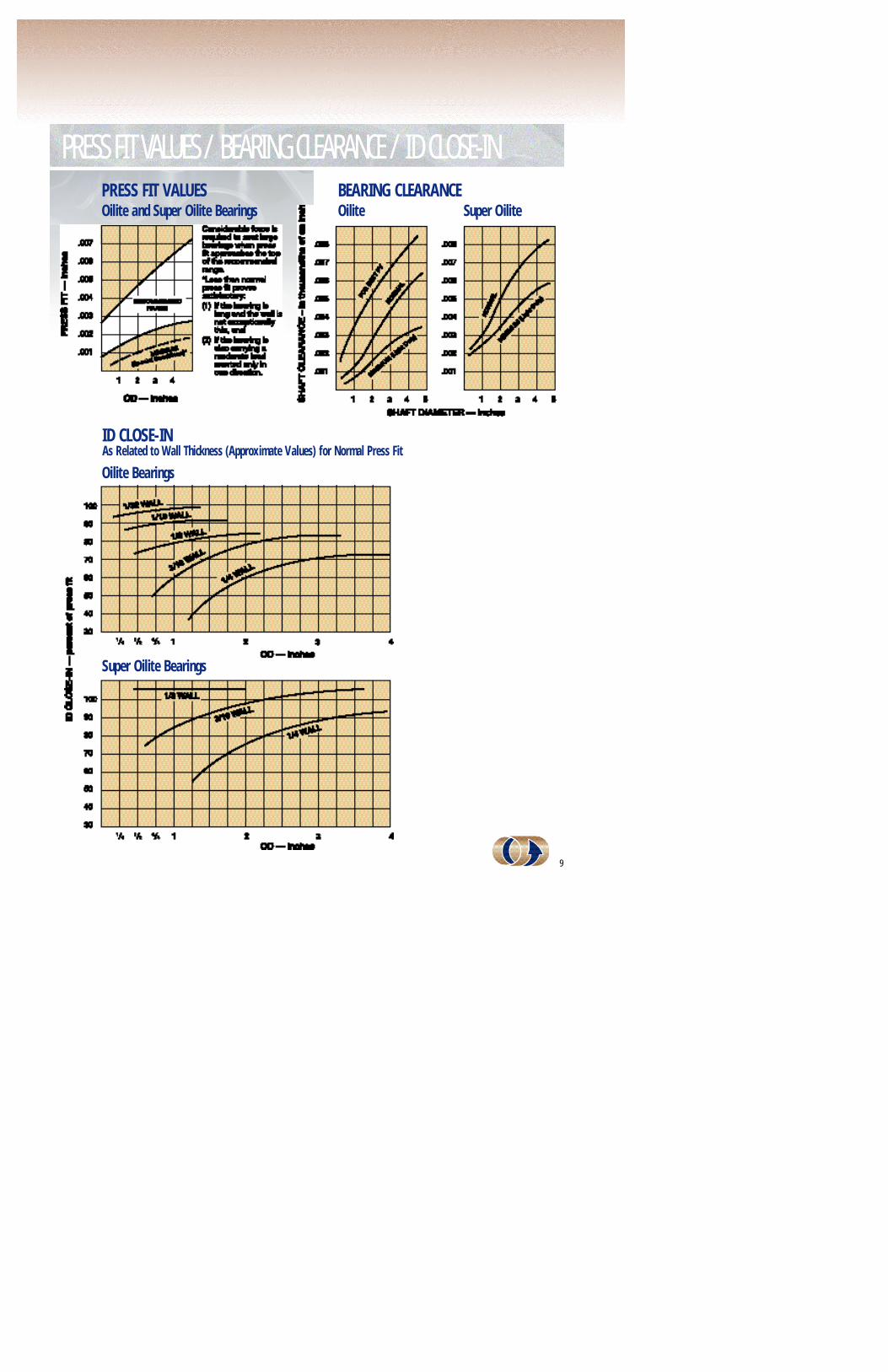
PRESS FIT VALUES / BEARING CLEARANCE / ID CLOSE-INPRESS FIT VA L U E SOilite and Super Oilite Bearings
BEARING CLEARANCEOilite Super Oilite
ID CLOSE-INAs Related to Wall Thickness (Approximate Values) for Normal Press Fit
Oilite Bearings
Super Oilite Bearings