general dimensions - home - cranedude · 2015-09-20 · general dimensions t ... ntf.,.... -365 ......
TRANSCRIPT
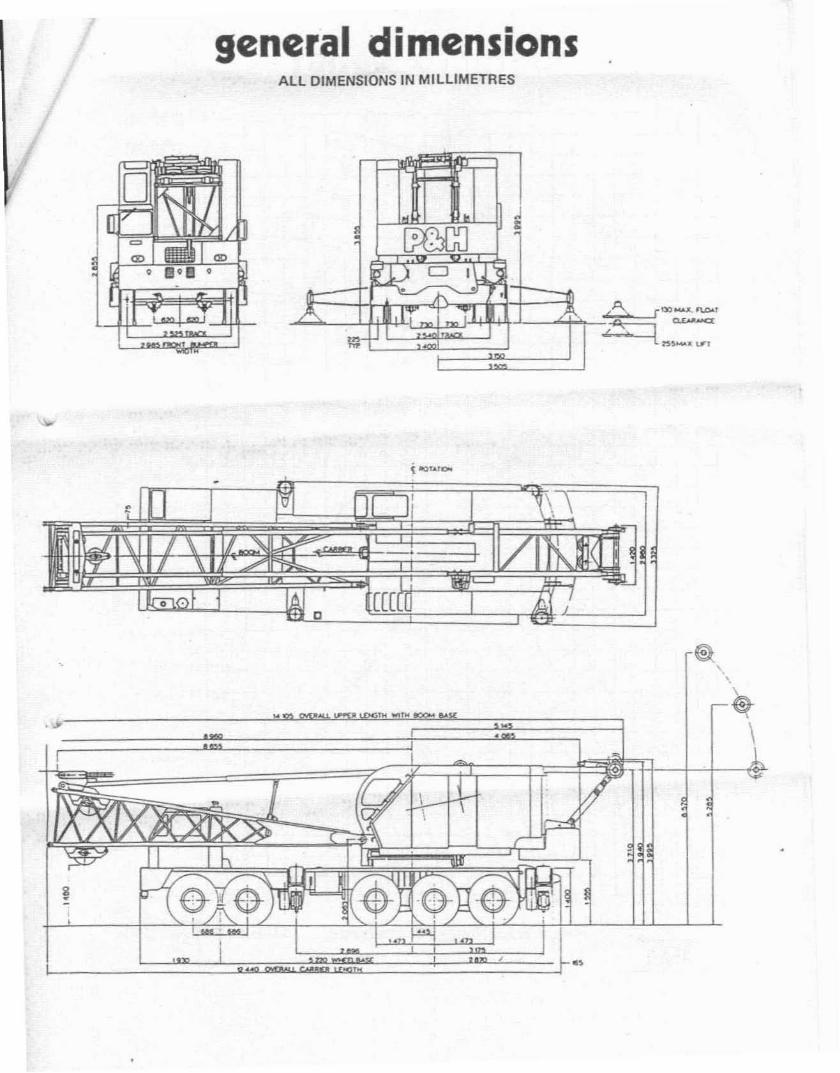
general dimensions
t
ALL DIMENSIONS IN MILLIMETRES
~
J
~t
'U CJ I
"----' ~ •~ . "1'1. ,5.
l:r J ",,":.
{ -oUIOo
\\-. ]
0eee
&'.
• '" ~ ~• j • \•
'IM
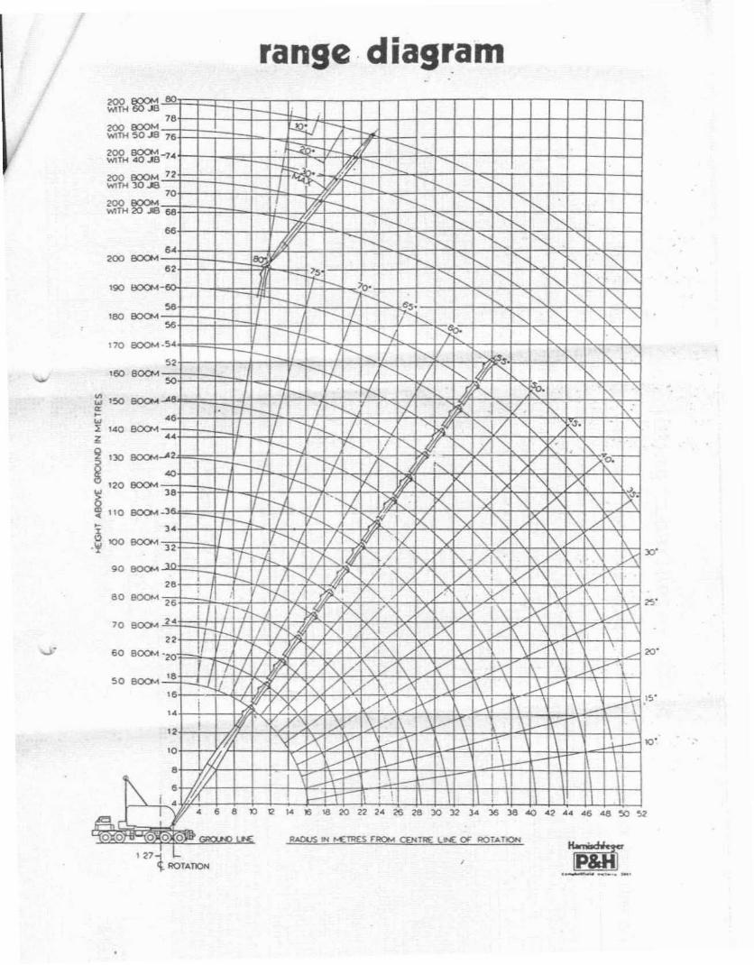
range· diagram
,
i ".\ .
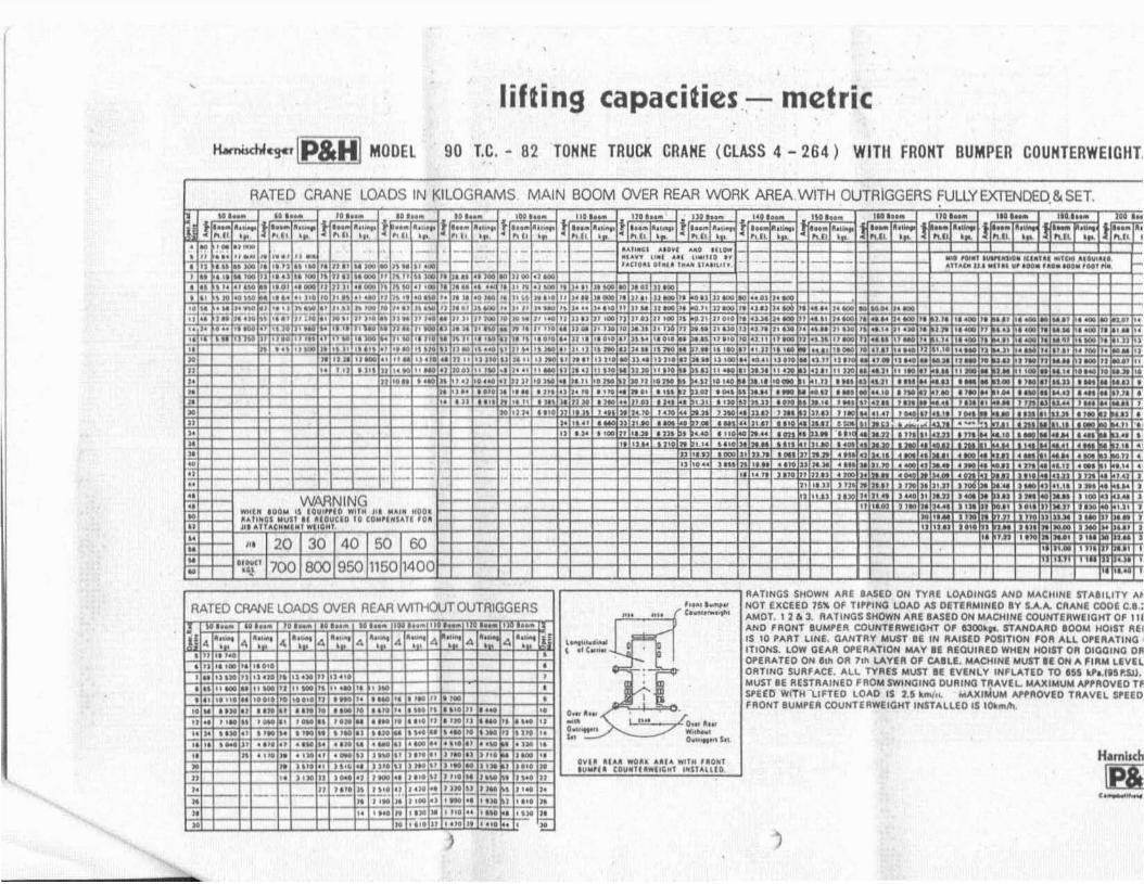
,lifting capacities.:- metric
H.mO<hIC!«'!P&H] MOOEl 90 lC. - 82 TOHHE TRUex CRAHE (CLASS 4 - 264) WiTII FROHT 8UMPER COUHTERWEIGlIl
RATED CRANE LOADS IN ~ILOGRAMS MAIN 800M OVER REAR WORK AREA WITH OUTRIGGERS FULLY EXTENDED. & SET.
f-
" ·,.t .-__ --..r;;' II _" , ..Il._ _' .,~, i " •• 'M1" .. ",.. ,._ '_01 ... ",. ,' ,. II
" " 11 ._ .. OJ'• _ 1,)"
","'n''i:ii'
~~.!.!!!....
.-
~::~~~::':: ~':.':~':'.:."::::'~:
.~
1 t~
J II II.... IIJ1n..• '" "...."n '.n
,......~"l1.1 •..:
. ,10 " .." ....
I ..................'
"'I I........
f=-.."I,,' iil ,;~
III It... IIU._ 1)._j ..... ··-t,- .,... ! ............."II' "." .. " I,
....... , All'" ..... ."..
~:~i:..·~~~i:~:.....:':':~~,,,·: 1-
, ..t. I .... I .....~ "II ,
-..._,~-
fOl_
t. ..... '"....~ "" ,
.1::'1=
.......,=...l! I" rd.;
"
===-.-,._'=c==WARNING
",..I .. '0010 II UUI"" WI' .. ". MAl. ,,00'U".GI MIIIl ...,OIlCIO 10 (OM'UIIH ...III ..n ..( ....1_' "II''''
"-,'.
1=.,-1-
MI_ 111_i. ••_ 1._ ..,....l! ".11' .l!"h'................ " ,,, --
I " I. iiTi iiiii "" ,ii1iii-I " M""" .... It '''I H_I II u.,,_ ""' .• _ II I •••,_ .. _ .. ""
"" I,. ..;; •••·•• ,)•• '.'.n..... 11I_'"11" .,;'_ .. ~.I!.:.!!!!."" _ " •.• "_ .. ,,.. ,.•'....... ",,_ .. .,u,,_ Jo_" .. , ,m .,:;; ,'''> l' ...,........ ,._ _ .. 'M." .. ".............. ...,,, ,... ,.
•• "" ", '0' "'.'..... ' '.. .."" , .',".. II' , 'UN " '
II" I" , ..,.". '" 1''' .,..... , 1 •• _ .M.UtU' I II... .. ,- _" ..
.. " • • "' .111 "N .. .'.. ,n' ..... .» __ '11If) '" II'I , ... "."
.~•• ". l't.. . ••.I~I
.....1!";;:IT
"•E•........;;!I..""E"....;;..
}
tol·:';' 1..1·=141·:""
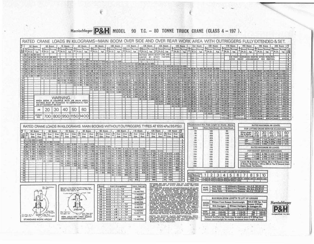
AATINGS SHOWN AAE 'ASED ON TYAe LD"OINGS AND MACHINe ST.... ILITV ...,.NOT f.XCU-O 15"11. OF TI'P1NQ LO...O AS OITIRMINIO av SA.... CAANI COOf. C.,.:AMOT. 12.3. AATINGS'HOWN AliI! IASIO~ MACHINI COUNTf.IlWE'QHT 0' '11AND 'AONT IUM,eR COUNnRwtlGHT 0' 630010;... STANO...AO 100M HOIST AllIS '0 MAT LINE. GANTR'" MUST If. IN RAISIO 'OSITtON 'OA ALL ~1"ATINa,
mON$. LOW GEAA Ol'I!RATION MAY IE Af.QUlllf.O WHEN HOIST OA OICiGING 0OI'f.AATEO ON lIlt OR 711' LAVlR 0' CAlLE. MADlINE MUST lION A "1'1104 LEvnORTlNCi SURfACE. ALL TYRES MUST U' IVlHLV 'Nil' LAUD TO 151 kt•.lI".su.MUST If. RUTAAINED ,AOM SWINGING DUAING TAAVlL. MAXIMUM M'ROVlO TJPUG 'W!THL1"EO LOAD IS U klft/.j, MAXIMUM """AOVf.O TI'IAVll S'IEOII'1I0NT 8UM,EA COUNTERWEIGHT INSTAllED IS IOklll""
.-,HamlKh
[pi
"_1_"--~
'.,_....-0 .....,... 1...
,.
o"u .,........ ~ UU .'M "0_'.U..,U ("'lin""",.., l'lUIHU
0.......-0..._.~
.... IN..,.."~ ...,,. ..
• n. ".- ..,'.. ,...'. '"'"II 1'1.,;-" ~
~'. "!! ':. 'M
iiii~
"".*~''."'r.. ,.r.. [· ...I,.I' ...
-"'.""'",,_to,,_ .. 'I"..... " ._, " ...u,. _ _ ;;1_ • ,.,. _ II It .,,. ..
• ... 01 tI. 11 ..,. • II...... ""01 ._ , 1
.i _u ._01 I'" ,1I,..r.;I ' It., )1.11 .... -nl I..
,. I'"'' , (_ •• Ifll J ," ..
-I.-w '~!t~~i' ~.!~I~J" I •• " I'.ol ''''1'"u ' ...... '"'11 •".r..
-
",.1..·..·1··.~
;;
I tI••,
.... I>
•
, '-..-."",...".' ..... ,....,,,1).,,, .. ,10""..""100 "_U••, ,."... 'UII ..
, "'., U" •n" , _ •
~~
"E"..•";;
t
,H",;"hf<g<' [P&HI MODEL 90 lC. - 80 TONNE TRUCK CRANE (CLASS 4 -197 ).
RATED CRANE LOADS IN KILOGRAMS-MAIN BOOM OVER SIDE AND OVER REAR WORK AREA WITH OUTRIGGERS FULLYEXrENDED&SET,
I}
,'~"
.,-
"Hi<-'.""
1"1_
'-1'I'ln .'
••.. IH"lhIlIJI.
h '_ ltl._Il ...otl_I1o_'" .. l'OI'" '10 ots....-.•__110-.
-.,.-'0'" ivl.oo.." IU.hi ..II. UOVlI.1,IIIU "",Ul .......11 .... 'I. """....
,,,._ 1- Itll_'MI_
",'-I"~ I'll~ •
~l i!f,!ij,~!2E:~
1111_
1.._ .... I_i:·----...~..._1- _
ii '01 "• * ~... 100 ".01 "" 'JI
01 1M '..• '" ,,,". '. ,."0 '" ,"'. 1.. '.."0 '.. "I... 'ft ".IN ,... "I.,. '.. ...'M 'It ,'.... 'M ,.
JOI ," 1.
tl~~I';11' 1_
·I..~I·'..'~ I'll' •fl""".. ".111 '"
o;O;-To-;:;;1 "I 0 ... 10....... I .·,~,I 01
I~if_"911\- rr' "''''I'~ - '!"., _............ -.. , ...:. "1""'"'~"ffIi'.~.;:J- ".I 1." "......... r:' "!'>' ....t " • "=if.".. :~,l~~ ',!1~..., ..lol"""·~.Il..·l-:JlY! I~,it ....~"J..I':~Ie 11 \i1 ...,,~ tf."'~ ..... . '~'N' ....::.~.' r. ''\1.''., 'r. ¥~:" '''~,"''"10- =r. I.~ 'fl \f.&Slf:"~::.l\!.i1ti~ ."."",,':::a."l'1. r.:¥oj:::::'" ~. t-~::~' '·\.\I.::'1N'r.~_~c_, ...,,,;;, l\m I" ,. -....._ .... iii. • ..'v,~r.u.",\'I, cd.,:,:~~.!~'l "r:"
'" ., ...........'1 -'*ilf'\•...••__., ,N'''.'' ._ ~•• , .....,~...... t·. fL"30'!,n: •• ~.,..: • • ...'l~,:.;o;.r~~J,J;;I:_ ..... -
11t._ I IXI 1_
'"NUII'
'100""'--;;;-"00"'"
'jlOi'ii"t....,.... ,, "',
--'00-......-u-11"""'-i'iiiiii
'1If_ 1_ 11'1_
1...... 1 II......
'="-I'''~''~r,,·I'I-·;;:;·-I~I.. u ,
._..1A1t·'~J·'"
iil~l:i:::i'".!.J.).'"
.I.u -'.'-'"""~.J.'. ,..IAI.'.J.'.Io,m.J.s.i.'"nr.-a, .•. 1"XII • •• t ••• ,,~
~1.:..!.:.1lt._
~.!..,:...1:..!.1
~·'."'."..i
MI_
~
~!A,.•;
;iil'-WI
JI~ I!.'"
-I·......'1'1', ,.
,* 1'*I, •• "
..-
..-f·_I·......'.. 1"1'111 •
..-0... 0 t. ...
~~,.....~a~.__~ I;:;::::,""----
'--rE--I :\'-t
t:~.~ 0- __-_..._ ~,-,_.._If "",,,,"
..-,=~l~iil--;;
20700
..;;;;;r.:;-_...... II t ...
WARNING,....1. 100" II IO~WII ""'" III .. ~11l 1l000,•.U'"U IOWU " ~IO\l(lD '0 CDIUII'''',1I IU.I,,,UC."I.' ..".,••,,-,In,
RATED CRANE lOADS IN KILOGRAMS MAIN BOOMS WITHOUTOUTRtGGER$ ~ES AT 655 kPaJ95P.SU
"
UIlI'fO....OWOll ....IIH.1
' ..........~-, ..
Cl.UTCH: Upc toll....... 14 - 2 OLB
TRANSMISSION AND PROP. SHAFTS: fUllcf"I'nodti R.T.O.9509 8..!o" pt'09fuli.... f_atd IpoI«lI, 2.--nc. 1810 lC,ielll'l1 Iyoke - O~nI Sofccr. Prop. Il'ldtl~~.front end i"le·.mcOwli Ih~lu 1810 1I';".lntet"," shifts 1100 1oIric1.
STEERING; R01l - -.m ~ toI'-,~ lIU" 28.0 10 1.03'~tfo 533 mm di_t., ttccring .......1-
fRONT AXLES: Shul.,~ fTC$-34·L tubut¥ f~t nIcs in1Ind.am. 2359 mm kin; pi" unvn.
REAR AXlES: Cllrk: TO 85000 pl_tlO'Y d,Mr. lfidem ,.Iu...i'" Inte,."le dllftn"tilh. 2540 mm irICk raul ,.tto 11.547:1
8RAKES: $c......ce - dull .. btlq cUcult wid\ frvnt II'Id .utbrakes on ~,.te circuiu. front IOotinvs 431 mmdil'.x 102 mm.......0•• 32261CtU-ll'e centimetr. toU£ fronl 1iniIlt_. 103SOUI,t(:Irntimetre .i, d>1mbco. Ru. 1iN"," 419 """ 4'... ]I: 178 mm...ide. Squ.~ centimet,. toUI ... 1;n1n; un. 232 ~... CI"li·....u. Ii, dllt"btrl. Tot" bntl<e linl"lIl'u.
POWER PlANT;
DESCRIPTIONEngine n'\IIkcModel numberT,o<No. cylinders800', ]I: ntOkeOlsplKcmcnl
CVd<A,;r indueuonCoolingSUt1inll0l~""9Co<r'ICl"'C11O'....Go-..ot. ~itPo_. Ol.n"",t. gr'01l
STANDARDCummiMNTf -365.,....•139.1 mm II 152.4 mm14013 eubOcc:en~.,-T_Uo."24 VOlt12 volt 7S -no wternl'tot6230 cubic: ClIfttlrncu, I 10Kn4 to 827 kJ"L2n Idlowcn n2300 '.JI.In.
SUSPENSION: R"'''a.."~ box IKtIon triclcm with lotqIHrodl. Setf a1i9'\inv bca'irIft: on IU:lp.,uiOt\ bun\! , Front:unlpn,lf)gbox seeUOl'I bogie with torque rocll. Scll .Iignlng boringl onbotft Itf'dl 01 boolc betr'lU.
WHEElS I RIMS: front 14.00 • 20 nIN. Rur 14.00 x 20 ,iIN........n
TYRE.$: Scftn_ 07114.00]1: 20·18 IMY tVra comotue ...i,"tvtM! 8tlId I\cp _odineIton-I.
fUEL TANK: 284 Ii". UpKJtV
RADIATOR: Uquid tVPt, nbbt, mounlld, ...."luI lube .ndlin tY9C ClOre. ThermOlt11 temperatura contrOl. Our~t;on
~f1!1t In t09 01 "'"It.CAB: 812 mm wiele __ cab 011"1 10 ,igtn ..de of "'91"'«li'~t. 11II windowI ate "".tV g1aa••Iecuic windlhlcktwiper Md windItIicId ....~. ,~ dISh ....th~mel.... 'Or~ puec. '""tmet.... ~.,t t.-npe:ra1ure I"'VI.cng;ne 01~ tw;C, IUd~ pugc ~l rwitchll.l-'e<;1richeinl, dome light, lUI assemblv. _"t co...t mirron - one on.ight Ii6c 01 c.b - one on 1cf1 ,Id. of elI"lcr, c;,ank down doorwindow, d~ - by lelt dcIe ...indows. AI, \/Cnt on ril''ll lide.
LIGHTING: F_ hc-.dlightl with toot opcnted dimme, Iwndl.SI09. tail. dir~. d • .....- -.'Cl teat liccnox pille lighu.T_ wuther proof _uu provitMd for U9P1r lighting d.....ingtrlftlit. In QIb - domIt ....t. i1kwnln~ted gaug.et. indicatorIi....u IOf hI·bum lights, dlreeti_1 lighu••mc.gen.ey IInh••Iighu Nw::I tow IIi, Pre:UUr, wlmingli;"l.
CAB AND BODY: Clb, .ngin. hoqd. Iront ~nd lide Pllllfh.front Ikl,u, equiptncnt bol(". dirt .Meldl .nd bOdy f1oo,p1atll1 formed from .....l n ..l. IMISCELLANEOUS EOUI .....ENT _ STO: l'yr. ;""Ition vaNeend ho_, 1_ 141 lIIuminiwn outriw-' ft-It and tool: \01
oPTIONS: Fronl ~lih"~ jade 110ft 'Of 3600 OPe,~uon. 6350lUloer- c:ounW-;"'t. blCk\Ip .....",11\9 d .....cc. 1220 mm •1720 """ *,urninium OUIfi9ger f1o~u tnd low tilhoucne floatl.
,
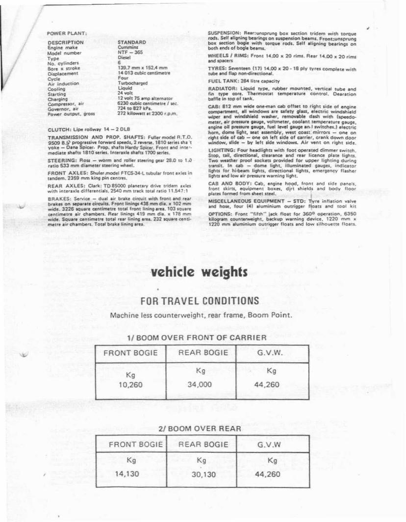
vehicle weights
FOR TRAVEl CONDITIONSMachine less counterweight, rear frame. Boom Point.
1/ BOOM OVER FRONT OF CARRIER
FRONT BOGIE REAR BOGIE G.V.W.
Kg Kg Kg
10,260 34,000 44,260
2/ BOOM OVER REAR
FRONT BOGIE REAR BOGIE G.v.w
Kg Kg Kg
14,130 30,130 44,260
upper data
CRANE 800MCRANE 800M - STANDARD: 60'0'· 115.25 metre! bWe'-"!Ith In IWO t«tiOlU, pin _td, V<1eo:>cbb11 UO 10 200'0·'161.0 moItnl Db,tllf "T." u~. 01*' dw'OII, CfOSf wctJon1515 nom Mdt: a 1210 mm 6etp. 5 olflcl boom point Ih._.eSO rnm R.D.. ",tt-frktlon t.trfnp.800M HOIST REEVING: 10 PIf'U of liM. Il)t1'Qr ""_no mm R.o.. I"ti-frictlon bul'iI9.HOOK 8LOCK - CRANE 800M:21 200 Kllogrlm 5Ongt. Shu~ Swivel Hook - 3 p.n L.inI40 BOOKI~ Two Sh....., SwiwI Hook - 5 Put Un.s.- 400 KlkogrIm ThtM She..... Swi¥eI Hook - 1 Pan lJne63 500 KnOll...... four Shet.... Swhoel Hook - 9 PIn Lin.81650 Kllogr""! F.... Shelve. SwMtHook - '0 Pan Une
FAIRLEAO:
TAG LINE WINDER:
J18: 20"0" 16.0 mittel besk Itt>tth In _ ..ctionI. pi.. eonl'IIeted. lJlut'ld1blc to &O'er 118.0 mll,,1 NbcIl... 1110'( ItMI,oc-n th/'Oll, etoU MCtlotl 610 mm wlcl 500 ....." de.ep. jibpolnt sh._ .20 mm R.D•• Intl.friction boo ifl9l. fluid IIrvt -~undttd. n...row rtrvl - OPlilllltli.
POWER PlANTENGINE _ CUMMINS N"SSP: 6 cylondef d,"" _, OUtoul120 kilowaltlll 1600 '.p.m. 'ullloIId 1Pted,
TRANSMISSION - COTTA: 3 speed. 2nd 9ttr nonntI (lClI!f1Idng:qloeed. 2.00 10 '.00 r.tio.
FUEL TANK: 28<C titrt aPKifV
BOOM HOISTCLUTCH: 585 mm di.. • '02 ....." .Mde bIf'Id IV'ClI Innrn.elt$lolfldino
8RAKE: 650 ....... di.... 16 mm ..~. btnd tVPllJltlrNII c:ontrlC'li"9 "lull wrtpH c$tt.ion
800M HOIST ASSEM8LY: lrodeoet'ldenl pbntlltY our fVDIwith VtU,n.1 'Itd'otl tnG IUUI'NIK bnke ptowidtl lor '''1'"'9tnd iowfti"9 boom under DQWtr Ind Ioc:king boom
BOOM HOIST DRUM: 330mm R.D... 121 mm Iont lor 19nvnc.tOIe 128 mitre ctblt capKllV. Anli·friction boo'I~.
l.INE DATA: Line tpeld - 1Io'l1i", 38 mlt,el""n. lowed",23 rnetttlmin. line poIli 6800 kiloerlml.
THIRD DRUMMounu on ""nlion 01 I,onl drum wll to left 01 tN'" drU'l'\.dOlI ACt ,ntetttrt wid'< tnY 1'IWId'l..... lunaion 01 Ironl end.ltld'lomltll ~lble. Opt>on.tl e><u. lor mtdI.... _th (nntlYPi Iltld'l_nl. 395 rnm r.d. a 152 nvn leno lor 16 mm ablt.10 m".. CIbl. ~tV.
LINE DATA: Lin. IDled _ ... metre I mill line DUll 3600kilOll'ImI.
FRONT DAUM IDIGGIDRUM fOR CRANE: «5 mm R.D. _ 352 mtIl IOIot 101 12 nvne.tbI•• Sin'" ltytt QIOKirv 20 mlitl 10ul~tY 195 Intlte
~"'.DRUM FOR CL..AMSHELL:445mmR.D. _ J52....." """lor19 mm cibl•. Siner. IlYe' ap.adtV 2S '""v. IOtll QPIIl:itV214 melll - ImGOth.
DRUM fOR DRAGLlNE: 445 nom R.D.a JS2 mrn Iof>g lew22 mm CIIbIe. Slngl, 11Ye' e>lP'(:lty 22 mtll. 10Ial ~rv170 ,AUft.
liNE DATA: Unt spetd - 50 Intl~ I min. lint pull 12J60kliOll..-rN
CLUTCH: 111 mrn 01"101. 102 mm wlcM Ul,mal ,~ing band_.8RAKE: 82'Smm 01"~ >< 121 mmwick tIlem" COf'II(Kling b..-.dfYPC. Hrdnulic ICI bnh and .,jdilion.. spritlg WI hydrwliCllllyOC-f.ltd 1I1I saf. bnb.
POWER lOWERING: Pllon.ltry te., rvpor POW'f lowC't1ng ltd.....hh 825 mm d;'. 0: 102 tom wid. tIIt.mll eonuxtltl1l btnd1'fPI b aU.
REAR ORUM (HOlST)DRUM FOR CRANE: - JI8:4<45nwn R.D.. 1t 352 I'NI'I IonQ 'Of19 fIV'\ ubIt. Single: I..,.,. ~rv 2S mette. Tou! eapc'rv21. ",un: - .moellh.
DRUM FOR ClAMSHELL:404SmmR.D.. a 352 mm ICM"lllor19 mtn able. Slntle tlY" e:.tPadrv 25 mell,. TOllol caPKiIY235 mllrt, ,rClOWd.
DRUM fOR ORAGLlNE: «5R.D.• 352 mrn long lor 19 mm~. Si...1e t.v', alYClIV 22 mun. TOI.I ~ly 111 mil...Groov>d
LINE DATA: LiM -.c:l - SO melt. I min. lJnt pull 12000kil~
CLUTCH: 1'11 mm Gia•• 102 mrn ...nei. band lYP'. OnltrMl"p'Mhn,.
BRAKE: 825 mrn di•• a 121 mnt .... idt btnd Iype ..tJn.rconllldine hydr8Ulic ICI bl'llkt tnd .sdilionll 'Dring WI h.,.drtullaU., CIPtf1Iled I.il ..f. br.kI.
POWER LOWERING: I"lM\tUry 9l!1t type pow., Iowe""llltd.with 825 ....." di... '02 ...... wid•• uI.rntl eonltKtlne btndIVPl br.ke.
MISC.
CONTROLS: full "_ j)OWIr hVCIr..,ric: 1V1I.m .1 96SO kP.Lint Oftl"'''.
G~NTRY: High 9.nttY. telelCOPitl1l thru P<Kltion, POW"r.ne.
SWING CLUTOI: Swono rnoU~1 throuth two .ltclflHftlll"llK-1t'\Ii"'I10lQUt- ,,"iu.
SWING BRAKE: 451' """ 0... a 64 mm wide O"l'IIed\IfI'e.tI!rOC1Oon IVP'. sprin; M1, hydrl'Jlic: ...Ie.....
COUNTERWEIGHT: "800 "II- I'ngl. pillU. pon c:onnet;led.rernovlblt ulin91'l'fd. rI"" WI in unit,.
FASTENING UPPER TO CARRIER
TYPE OF FASTENING: 6 IdlunlOle hook roll.tl. ,4outllt1,0111. 2<1ouO&e "Ill'.
SWING ROLLERS: JO roIltn 121 """" dil. on '995 mm P.O.l"..e 'Ollt. c..c:se.SWING GEAR: Intlfn. C\oIt 110 luth 1115 mm '.0.
SWING SPEED: 3.88 R.P.M.
•carrier\'\'EIGIfT: lroduding IU"II. hydflutlc OUUIfte'I. 1I0.lt. ,oil"corclt .•nd li,". 28.85 lonntl.
FRAME: front section it IbocI11lCl hom 'S' rnm _ :26 kilo·"1m cftlN'lel. R.1t Iot<lion il • IIbtICl~ bo_ ICCtion S02 rnmdftP.eroub....:l1ftd re'ntOlOld f,ont~f 01 '0 mm bt«1p.te. H""" ,ulf'4th low .noy It'" p1.tt lIMd "'I~. T_lOOP'S lront It'd r.lf.R~ nit tr_ wction iJlttndtrd.
OUTRIGGER BOXES: four 141 Ilbroated oncSIpI_1 boauof high'lIt.ngth 1_ .1l0V lltel 1)1'". f,onl ...:l tilt bo.., I'.pin CO"ntCled .nc:l ,emoVlbre.
dataOUTRIGGER 8EAMS: Fou' "1 rbialed ,.inforc:ecl boa<celion belml 01 lIigl'l ......9U1 low .,loV Ilul l)l'le. 8..' ....ul_1QOPJ 10 lully Ullnded l)01ition 01 3 ISO mm from IontilUd·in., anlr. line 01 ~rrie, 10 I;ef\lI't lint of OUIt" 11011 pm onhydrlUlc b.....I.
HYDRAUUC OUTRIGGER ASSEM8LY: Eighl lSI dOUble:K1M.t hycl.....1>c cvtirockn prOO'tdt iI'IcI«M,l(\tnl "-iZOIllal """".nOctl _"I 01 etd't belm. Elotc1ric: lOI.noid IC'IQleGdi~ionII control~ eperilid Irom rwo conuoi ~h:EId\ pIfItl (onltob _ Iicle only.
o ~J...(4.Um)
9'''-3/4"(3.01",)
(3J~.,--1-----
r
I,13"'2:..01101)
~~~;f;----I 11".2-1/2"~O'4-J/~------ 13,.42",\
------ <3.llII7Il ---~11"-6"
(3.s3m)
180 BTC
1105J286
------,
>-.. .15"13.lmm)-2"-4-117'
",+",",:,..,1 ,,,.,
, ,13.nlft) "
.·1"---(2.45ml---
t.,,, "" q;,.-:J'<r---- T-____IROTATION t6..•.1n;2~/C\;[·?~~=L ~(SI3mJ ,7 / \
J13 -4-:1'4- TAIL SWINO RADIUS
(•. IOrn) / '.
/~// /
12-9"13.D3m)
2','·112"(,11"'1
11·1/2" - 4""-1/2"
~~;".,19','·11"" WHEEl.S"SE(S.82ml
_______ ~~~~~~I--O-'-'-.A-'-'-CAAAI£R~"N'G"'"N _
7 -liZ"(2.1 .....'
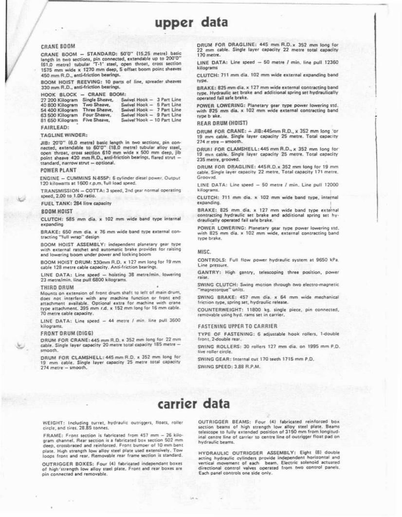
1- ..·...112- OVERAll UPf>EA LENGTH WITH 800M SUE114.1JmJ 29.... _
I
(a.Hon)
__--,i~,
o
NOTE: All des1ins. specrticaUOIl$ and compOnl!I1IS 01 the equipment de:>cnbed above are sul)ject to cninge atthe manufacturer's s.ole dls.c;,tetion al an)' time Wltnout ad...al1C(' notlce. Data published herem 15 InformationalIn nature and shall not be construed to warrant sUitablllty of lhe machIne for any partIcular purpose as pef".lorman<;~ m;,y vary ·.... ith the conditIonS encounle,eo. The only ....arrant) apphcable 'S our sl;,n<:!iHd '....rinenwarranty for thiS mach'ne. Manufaclured and sold in conformance .....,th U S Department of Commerce Com·mercial Standard CS-90·58
oTX·492Sp·9 D5·380 Litho in U.S.A.
9OConl
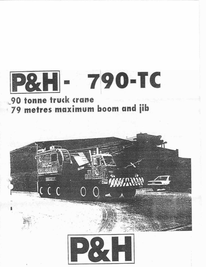
P&H® 790-leo
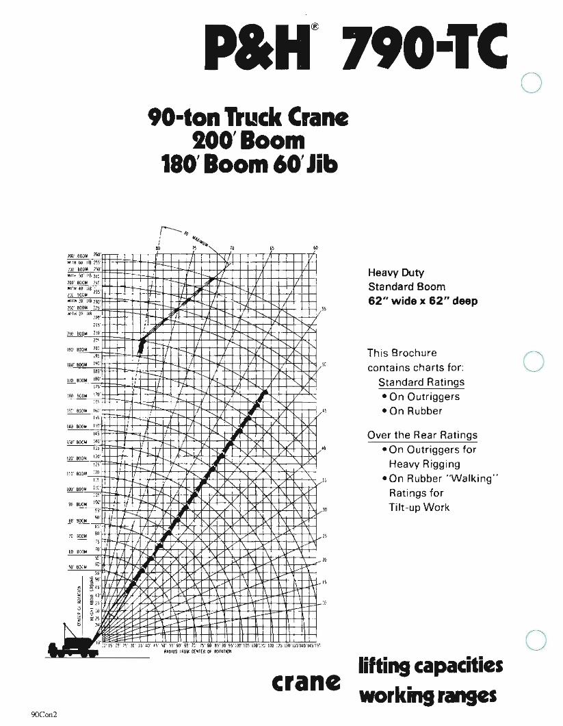
'O-ton Truck Crane100'Boom
180'Boom 60'Jib
"
o
Heavy DutyStandard Boom62" wide x 62" deep
Over the Rear Ratings
• On Outriggers forHeavy Rigging
• On Rubber "Walking"Ratings forTilt-up Work
This Brochure
contains charts for:Standard Ratings
• On Outriggers
• On Rubber
--+f-I-++H H
"l: '" v"--, '" "~ ,V'I. "-..: " ~"J)
"- '/'~ /I .,
,It
!
"/
zoc;' aoOIll ""WI!" 60' 118 2'i,"
m 500lil ;)1)'
\\'IT~ .' )IS 1~~
lOtI" llOColoi 1'('l'I'l·H.O liB' .l:( 5CCoW m,,1ft, ;G llflar
'" '"" 2i';"
N"M l('
'" 111;"
il,"
m BCOw 110
1('"
,,,' BOO"," ,~
.9~
lill' BOOlil I"'~'
I!l'
,ro 1lC41'!t.• '"Pl"
IW ~.. I~
:!'.
1'1) BOO" 1&:'-
l>~'
).,.J",". &)(411 •
In,
\;,o'SoXIII l":;'rho
IllY 803.... 1M'
121"
-"
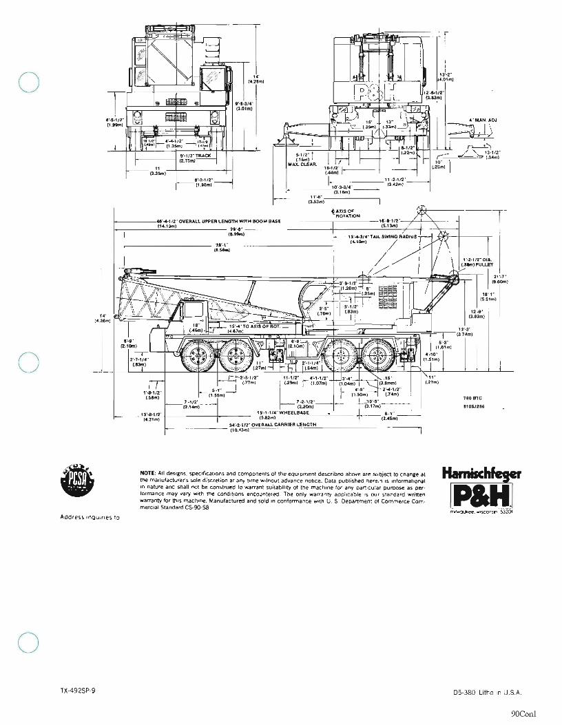
cranelifting capacitiesworking ranges
o
9OCon2
opaH 790-Te
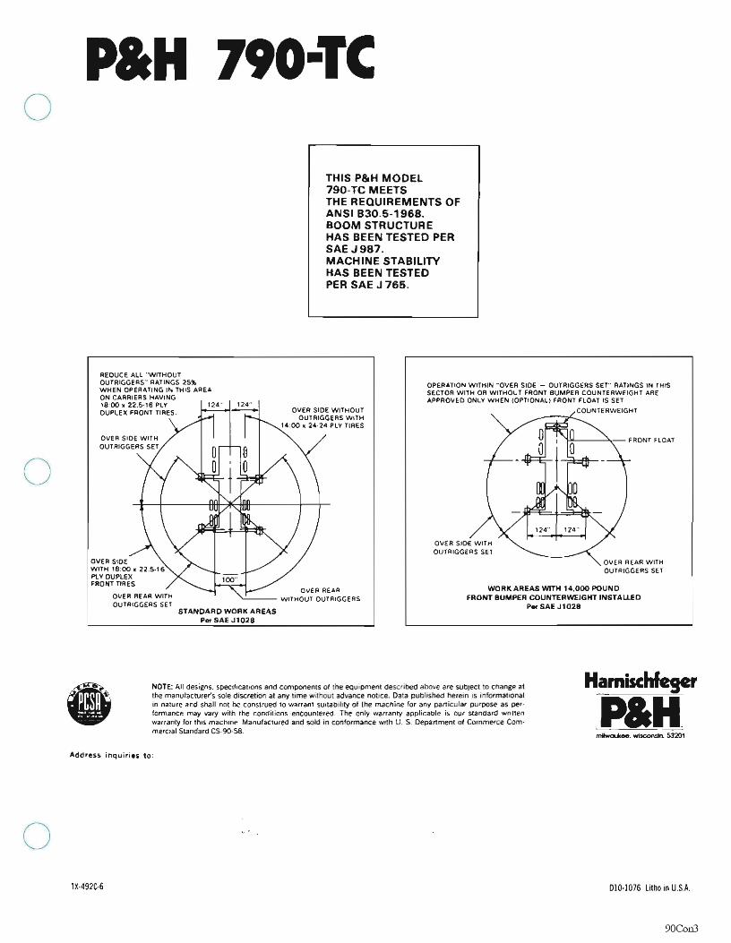
THIS P&H MODel790-TC MEETSTHE REQUIREMENTS OFANSI B30.5-1968.BOOM STRUCTUREHAS BEEN TESTED PERSAEJ987.MACHINE STABILITYHAS BEEN TESTEDPER SAE J 765.
OVER REAR WITl-lOUTRIGGERS SET
~,----"'_FRONT FLOAT
WORK AREAS WITH 1••000 POUNDFRONT BUMPER COUNTERWEIGHT INSTALLED
P.SAEJ1028
OVER SIDE WITHOUTRIGGERS SEl
OPERATION WITHIN hOVER sloe - OUTRIGGERS SET" RATINGS IN THISSECTOR WITH OR WITHOUT FRONT BUMPER COUNTERWEIGHT AREAPPROVED ONLY WHEN (OPTIONAL! FRONT FLOAT IS SET
__-,-....c.:...COUNTERWEIGHTOVER SIDE WITHOUTOUTRIGGERS WITH
'.0011 24·24 PLY TIRES
OVER REAR"-'--- WITHOUT OUTRIGGERS
STANDARD WORK AREASPerSAEJ1028
REOUCE ALL 'WITHOUTOUTRIGGERS" RATINGS 25~
WHEN OPERATING IN THIS AREAON CARRIERS HAVING18'00 ~ 22.5-16 PLY 124" 124"DUPLEX FRONT TIRES
OVER SIDEWITH 18-00 II 22 5-16PLY QUPLEXFRQNTTIRES
OvER REAR WITHOUTRIGGERS SET
o
•NOTE: All designs. specifications and components 01 the equlDment described above are subject to change atthe manufacturer's sole discretion at any time Without advance nottce. Data published herein IS IOformatll)natIn nature and shaH not be construed to warrant SUItability 01 the machine for any particular purpose as oer·formance may vary WIth the conditions encountered. The ooly warranty applicable is our standard wrttlenwarranty lor thIs, machine. Manufactured and sold in conformance WIth U. S. Department 01 Commerce Com·merClal Standard C5-90·58.
Hamischfegcr
paNAddress inquiries to:
o1'·492C·G 010·1076 Litho in U.S.A.
9OCon3
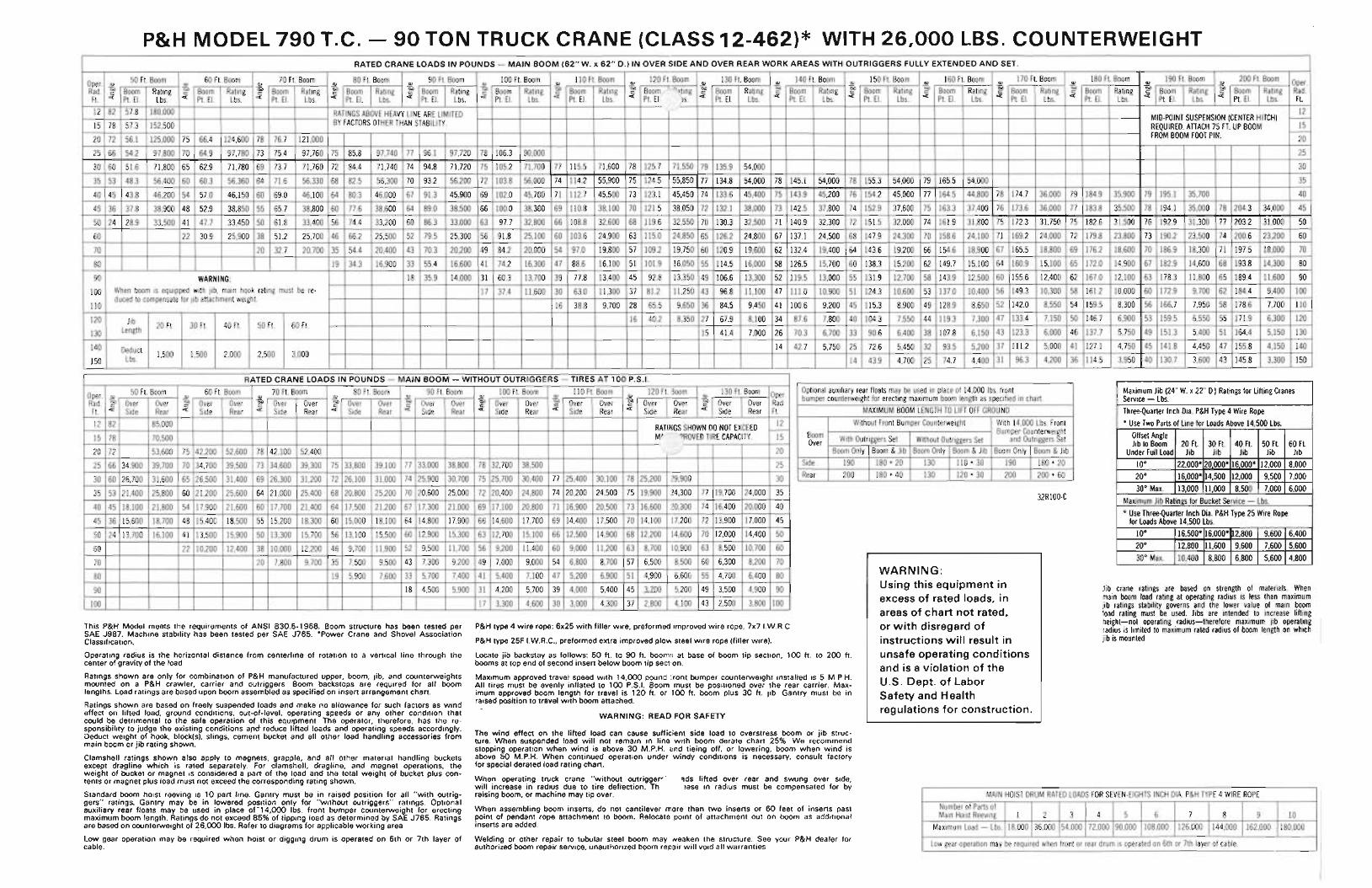
P&H MODEL 790 T.C. - 90 TON TRUCK CRANE (CLASS 12-462)* WITH 26,0'00 LBS. COUNTERWEIGHT
Jib crane ratings are based on strength of materials. Whenmain boom load rating at operating radius is less than maximumjib ratings stability governs and the lower value of main boomload rating must be used. Jibs are intended to increase liftingheight-not operating radius-therefore maximum jib operatingradius is limited to maximum rated radius of boom length on whichjib is mounted.
32R100-C
MAIN HOIST DRUM RATED LOADS FOR SEVEN-EIGHTS INCH DIA. P&H TYPE 4 WIRE ROPENumber of Parts ofMain Hoist Reeving 1 2 3 4 5 6 7 8 9 10
Maximum Load - Lbs. 18,000 36,000 54,000 72,000 90,000 108,000 126,000 144,000 162,000 180,000
Low gear·operation may be required when front or rear drum is operated on 6th or 7th layer of cable.
WARNING:Using this equipment inexcess of rated loads, inareas of chart not rated,or with disregard ofinstructions will result inunsafe operating conditionsand is a violation of theU,S. Dept. of LaborSafety and Healthregulations for construction.
WARNING: READ FOR SAFETY
P&H type 4 wire rope: 6x25 with filler wire, preformed improved wire rope, 7x7 I.W.R.C.
P&H type 25F I.W.R.C., preformed extra improved plow steel wire rope (filler wire).
Locate jib backstay as follows: 50 ft. to 90 ft. booms at base of boom tip section; 100ft. to 200 ft.booms at top end of second insert below boom tip section.
Maximum approved travel speed with 14,000 pound ront bumper counterweight installed is 5 M.P.H.All tires must be evenly inflated to 100 P.S.I. Boom must be positioned over the rear carrier. Maximum approved boom length for travel is 120 ft. or 100ft. boom plus 30 ft. jib. Gantry must be inraised position to travel with boom attached.
The wind effect on the lifted load can cause sufficient side load to overstress boom or jib structure. When suspended load will not remain in line with boom derate chart 25%. We recommendstopping operation when wind is above 30 M.P.H. (nd tieing off, or lowering, boom when wind isabove 50 M.P.H. When continued operation under windy conditions is necessary, consult factoryfor special derated load rating chart.
When operating truck crane "without outrigger"" 'Ids lifted over rear and swung over side,will increase in radius due to tire deflection. Th lase in radius must be compensated for byraising boom, or machine may tip over.
When assembling boom inserts, do not cantilever more than two inserts or 60 feet of inserts pastpoint of pendant rope attachment to boom. Relocate point of attachment out on boom as additionalinserts are added.
Welding or other repair to tubular steel boom may Neaken the structure. See your P&H dealer forauthorized boom repair service, unauthorized boom repair will void all warranties.
This P&H Model meets the requirements of ANSI B30.5-1968. Boom structure has been tested perSAE J987. Machine stability has been tested per SAE J765. ·Power Crane and Shovel AssociationClassification.
Operating radius is the horizontal distance from centerline of rotation to a vertical line through thecenter of gravity of the load.
Ratings shown are only for combination of P&H manufactured upper, boom, jib, and counterweightsmounted on a P&H crawler, carrier and outriggers. Boom backstops are required for all boomlengths. Load ratings are based upon boom assembled as specified on insert arrangement chart.
Ratings shown are based on freely suspended loads and make no allowance for such factors as windeffect on lifted load, ground conditions, out-of-Ievel, operating speeds or any other condition thatcould be detrimental to the safe operation of this equipment. The operator, therefore, has the responsibility to judge the existing conditions a.nd- reduce lifted loads and operating speeds accordingly.Deduct weight of hook, block(s), slings, cement bucket and all other load handling accessories frommain boom or jib rating shown.
Clamshell ratings shown also apply to magnets, grapple, and all other material handling bucketsexcept dragline which is rated separately. For clamshell, dragline, and magnet operations, theweight of bucket or magnet is considered a part of the load and the total weight of bucket plus contents or magnet plus load must not exceed the corresponding rating shown.
Standard boom hoist reeving is 10 part line. Gantry must be in raised position for all "with outriggers" ratings. Gantry may be in lowered position only for "without outriggers" ratings. Optionalauxiliary rear floats may be used in place of-14,000 Ibs. front bumper counterweight for erectingmaximum boom length. Ratings do not exceed 85% of tipping load as determined by SAE J765. Ratingsare based on counterweight of ~6,000 Ibs. Refer to diagrams for applicable working area.
Low gear operation may be required when hoist or digging drum is operated on 6th or 7th layer ofcable.
RATED CRANE LOADS IN POUNDS - MAIN BOOM (62"W. x 62" D.) IN OVER SIDE AND OVER REAR WORK AREAS WITH OUTRIGGERS FULLY EXTENDED AND SET.
Oper. <1.l50 Ft. Boom
<1.l60 Ft. Boom
Q.)70 Ft.'Boom
<1.l80 Ft. Boom
<1.l90 Ft. Boom
<1.l100 Ft. Boom
<1.l110 Ft. Boom
<1.l120 Ft. Boom
<1.l130 Ft. Boom
<1.l140 Ft. Boom
<1.l150 Ft. Boom
<1.l160 Ft. Boom
<1.l170 Ft. Boom
<1.l180 Ft. Boom
<1.l190 Ft. Boom
<1.l200 Ft. Boom Oper.
Rad. ~ Boom Rating ~ Boom Rating g,o Boom Rating ~ Boom Rating ~ Boom Rating ~ Boom Rating ~ Boom Rating ~ Boom ""ting g,o Boom Rating ~ Boom Rating ~ Boom Rating ~ Boom Rating tiD Boom Rating ~ Boom Rating ~ Boom Rating ~ Boom Rating Rad.c:Ft. <t: Pt.E1. Lbs. <t: Pt. EI. Lbs. <t: Pt. EI. Lbs. <t: Pt. EI. Lbs. <t: Pt. EI. Lbs. <t: Pt. EI. Lbs. <t: Pt. EI. Lbs. <t: Pt. EI )s. <t: Pt. EI. Lbs. <t: Pt. EI. Lbs. <t: Pt. EI. Lbs. <t: Pt. EI. Lbs. <t: Pt. EI. Lbs. <t: Pt. EI. Lbs. <t: Pt. EI. Lbs. <t: Pt. EI. Lbs. Ft.12 82 57.8 180,000 RATINGS ABOVE HEAVY LINE ARE LIMITED 12
BY FACTORS OTHER THAN STABILITY.-- MID-POINT SUSPENSION (CENTER HITCH) -
15 78 57.3 152,500 REQUIRED. ATIACH 75 FT. UP BOOM 15FROM BOOM FOOT PIN. -
20 72 56.1 125,000 75 66.4 124,600 78 76.7 121,000 20
25 66 54.2 97,800 70 64.9 97,780 73 75.4 97,760 75 85.8 97,740 77 96.1 97,720 78 106.3 90,000 25
30 60 51.6 71,800 65 62.9 71,780 69 73.7 71,760 72 84.4 71,740 74 94.8 71,720 75 105.2 71,700 77 115.5 71,600 78 125.7 71,550 79 135.9 54,000 30
35 53 48.3 56,400 60 60.3 56,360 64 71.6 56,330 68 82.5 56,300 70 93.2 56,200 72 103.8 56,000 74 114.2 55,900 75 124.5 55,850 77 134.8 54,000 78 145.1 54,000 78 155.3 54,000 79 165.5 54,000 35
40 45 43.8 46,200 54 57.0 46,150 60 69.0 46,100 64 80.3 46,000 67 91.3 45,900 69 102.0 45,700 71 112.7 45,500 73 123.1 45,450 74 133.6 45,400 75 143.9 45,200 76 154.2 45,000 77 164.5 44,800 78 174.7 36,000 79 184.9 35,900 79 195.1 35,700 40
45 36 37.8 38,900 48 52.9 38,850 55 65.7 38,800 60 77.6 38,600 64 89.0 38,500 66 100.0 38,300 69 110.8 38,100 70 121.5 38,050 72 132.1 38,000 73 142.5 37,800 74 152.9 37,600 75 163.3 37,400 76 173.6 36,000 77 183.8 35,500 78 194.1 35,000 78 204.3 34,000 45
50 24 28.9 33,500 41 47.7 33,450 50 61.8 33,400 56 74.4 33,200 60 86.3 33,000 63 97.7 32,800 66 108.8 32,600 68 119.6 32,550 70 130.3 32,500 71 140.9 32,300 72 151.5 32,000 74 161.9 31,800 75 172.3 31,750 75 182.6 31,500 76 192.9 31,300 77 203.2 31,000 50
60 22 30.9 25,900 38 51.2 25,700 46 66.2 25,500 52 79.5 25,300 56 91.8 25,100 60 103.6 24,900 63 115.0 24,850 65 126.2 24,800 67 137.1 24,500 68 147.9 24,300 70 158.6 24,100 71 169.2 24,000 72 179.8 23,800 73 190.2 23,500 74 200.6 23,200 60
70 20 32.7 20,700 35 54.4 20,400 43 70.3 20,200 49 84.2 20,000 54 97.0 19,800 57 109.2 19,750 60 120.9 19,600 62 132.4 19,400 64 143.6 19,200 66 154.6 18,900 67 165.5 18,800 69 176.2 18,600 70 186.9 18,300 71 197.5 18,000 70
80 19 34.3 16,900 33 55.4 16,600 41 74.2 16,300 47 88.6 16,100 51 101.9 16,050 55 114.5 16,000 58 126.5 15,700 60 138.3 15,200 62 149.7 15,100 64 160.9 15,100 65 172.0 14,900 67 182.9 14,600 68 193.8 14,300 80
90 WARNING: 18 35.9 14,000 31 60.3 13,700 39 77.8 13,400 45 92.8 13,350 49 106.6 13,300 52 119.5 13,000 55 131.9 12',700 58 143.9 12,500 60 155.6 12,400 62 167.0 12,100 63 178.3 11,800 65 189.4 11,600 90
100 When boom is equipped with jib, main hook rating must be reo 17 37.4 11,600 30 63.0 11,300 37 81.2 11,250 43 96.8 11,100 47 111.0 10,900 51 124.3 10,600 53 137.0 10,400 56 149.3 10,300 58 161.2 10,000 60 172.9 9,700 62 184.4 9,400 100
110duced to compensate for jib attachment weight.
16 38.8 9,700 28 65.5 9,650 36 84.5 9,450 41 100.6 9,200 45 115.3 8,900 49 128.9 8,650 52 142.0 8,550 54 159.5 8,300 56 166.7 7,950 58 178.6 7,700 110
120 Jib 16 40.2 8,350 27 67.9 8,100 34 87.6 7,800 40 104.3 7,550 44 119.3 7,300 47 133.4 7,150 50 146.7 6,900 53 159.5 6,550 55 171.9 6,300 12020 Ft. 30 Ft. 40 Ft. 50 Ft. 60 Ft.
130 Length 15 41.4 7,000 26 70.3 6,700 33 90.6 6,400 38 107.8 6,150 43 123.3 6,000 46 137.7 5,750 49 151.3 5,400 51 164.4 5,150 130
140 Deduct 14 42.7 5,750 25 72.6 5,450 32 93.5 5,200 37 111.2 5,000 41 127.1 4,750 45 141.8 4,450 47 155.8 4,150 140
150 Lbs. 1,500 1,500 2,000 2,500 3,00043.9 4,700 25 74.7 4,400 31 96.3 4,200 36 114.5 3,950 40 130.7 3,600 43 145.8 3,300 15014
RATED CRANE LOADS IN POUNDS - MAIN BOOM - WITHOUT OUTRIGGERS - TIRES AT 100 P.S.1.
Oper. <1.l50 Ft. Boom
<1.l60 Ft. Boom 70 Ft. Boom 80 Ft. Boom
<1.l90 Ft. Boom
<1.l100 Ft. Boom
<1.l110 Ft. Boom
<1.l120 Ft. 300m
<1.l130 Ft. Boom Oper. Optional auxiliary rear floats may be used in place of 14,000 Ibs. front Maximum Jib (24" W. x 22" D.) Ratings for Lifting Cranes
<1.l <1.l bumper counterweight for erecting maximum boom length as specified in chart. Service - Lbs.Rad. ~ Over Over ~ Over Over ~ Over Over ~ Over Over tiD Over Over ~ Over Over ~ Over Over ]J Over Over ~ Over Over Rad.c:Ft. <t: Side Rear <t: Side Rear <t: Side Rear <t: Side Rear <t: Side Rear <t: Side Rear <t: Side Rear <t: Side Rear <t: Side Rear Ft. MAXIMUM BOOM LENGTH TO LIFT OFF GROUND Three-Quarter Inch Dia. P&H Type 4 Wire Rope
12 82 85,000 RATINGS SHOWN DO NOT EXCEED 12 Without Front Bumper Counterweight With 14,000 Lbs. Front * Use Two Parts of Line for Loads Above 14,500 Lbs.- Bumper Counterwei§ht
15 78 70,500 M' ')ROVED TIRE CAPACITY. 15 Boom With Outriggers Set Without Outriggers Set and Outriggers et Offset AngleOver Jib to Boom 20 Ft. 30 Ft. 40 Ft. 50 Ft. 60 Ft.
20 72 53,600 75 42,200 52,600 78 42,100 52,400 20 Boom Only Boom &Jib Boom Only Boom &Jib Boom Only Boom &Jib Under Full Load Jib Jib Jib Jib Jib
25 66 34.900 39,700 70 34,700 39,500 73 34,600 39,300 75 33,800 39,100 77 33,000 38,800 78 32,700 38,500 25 Side 190 180 + 20 130 110 + 30 190 180 + 20 10° 22,000* 20000* 16000* 12,000 8,000
30 60 26,700 31,600 65 26,500 31,400 69 26,300 31,200 72 26,100 31,000 74 25,900 30,700 75 25,700 30,400 77 25,400 30,100 78 25,200 29,900 30 Rear 200 180 + 40 130 120 + 30 200 200 + 60 20° 16,000* 14,500 12,000 9,500 7,000
35 53 21,400 25,800 60 21,200 25,600 64 21,000 25,400 68 20,800 25,200 70 20,600 25,000 72 20,400 24,800 74 20,200 24,500 75 19,900 ;~4,300 77 19,700 24,000 35 30° Max. 13,000 11,000 8,500 7,000 6,000
40 45 18,100 21,800 54 17,900 21,600 60 17,700 21,400 64 17,500 21,200 67 17,300 21,000 69 17,100 20,800 71 16,900 20,500 73 16,600 20,300 74 16,400 20,000 40Maximum Jib Ratings for Bucket Service - Lbs.
45 36 15,600 18,700 48 15,40C 18,500 55 15,200 18,300 60 15,000 18,100 64 14,800 17,900 66 14,600 17,700 69 14,400 17,500 70 14,100 [7,200 72 13,900 17,000 45* Use Three-Quarter Inch Dia. P&H Type 25 Wire Rope
for Loads Above 14,500 Lbs.
50 24 13,700 16,100 41 13,500 15,900 50 13,300 15,700 56 13,100 15,500 60 12,900 15,300 63 12,700 15,100 66 12,500 14,900 68 12,200 [4,600 70 12,000 14,400 50 10° 16,500* 16,000* n2,800 9,600 6,400
60 22 10,200 12,400 38 10,000 12,200 46 9,700 11,900 52 9,500 11,700 56 9,200 11,400 60 9,000 11,200 63 8,700 10,900 63 8,500 10,700 60 20° 12,800 11,600 9,600 7,600 5,600
70 20 7,800 9,700 35 7,500 9,500 43 7,300 9,200 49 7,000 9,000 54 6,800 8,700 57 6,500 8,500 60 6,300 8,200 70 30° Max. 10,400 8,800 6,800 5,600 4,800
80 19 5,900 7,600 33 5,700 7,400 41 5,400 7,100 47 5,200 6,900 51 4,900 6,600 55 4,700 6,400 80
90 18 4,500 5,900 31 4,200 5,700 39 4,000 5,400 45 ..3.lO0 5,200 49 3,500 4,900 90
100 17 3,300 4,600 30 3,000 4,300 37 2,800 4,100 43 2,500 3,800 100
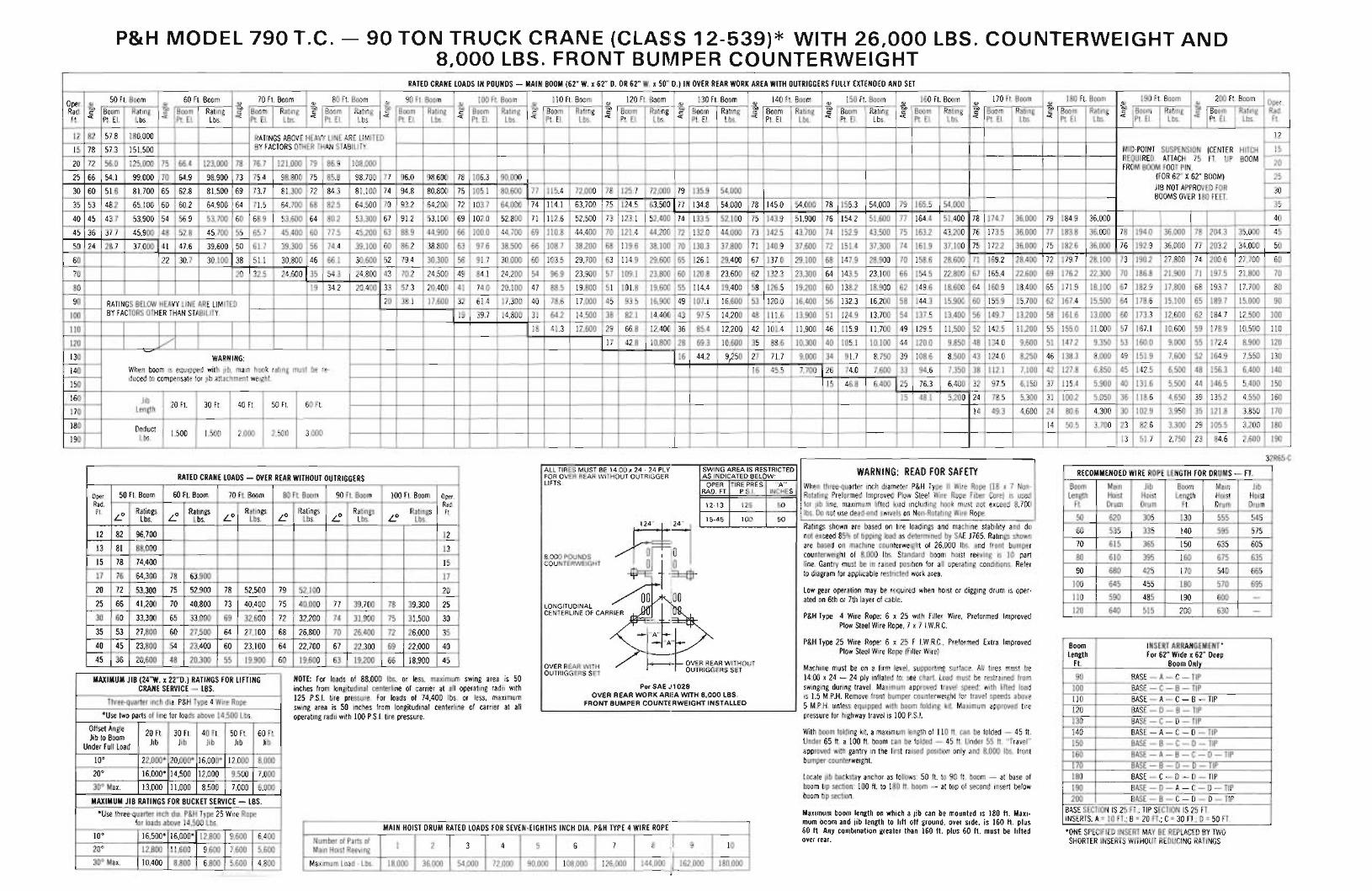
P&H MODEL 790 T.C. - 90 TON TRUCK CRANE (CLASS 12-539)* WITH 26,000 LBS. COUNTERWEIGHT AND8,000 LBS. FRONT BUMPER COUNTERWEIGHT
RATED CRANE LOADS IN POUNDS - MAIN BOOM (62" W. x 62" D. OR 62" W. x 50" D.) IN OVER REAR WORK AREA WITH OUTRIGGERS FULLY EXTENDED AND SET
Oper. 50 Ft. Boom 60 Ft. BoomIV
70 Ft. Boom 80 Ft. BoomIV 90 Ft. Boom 100 Ft. Boom 110 Ft. Boom 120 Ft. Boom 130 Ft. Boom
IV140 Ft. Boom
IV150 Ft. Boom
IV160 Ft. Boom 170 Ft. Boom
IV180 Ft. Boom
IV190 Ft. Boom
IV200 Ft. Boom Oper.IV IV IV IV IV IV IV IV
Rad. ~ Boom Rating ~ Boom Rating ~ Boom Rating ~ Boom Rating ~ Boom Rating ~ Boom Rating ~ Boom Rating ~ Boom Rating ~ Boom Rating ~ Boom Rating ~ Boom Rating ~ Boom Rating ~ Boom Rating ~ Boom Rating ~ Boom Rating ~ Boom Rating Rad.Ft. c:x: Pt. EI. Lbs. c:x: Pt. EI. Lbs. c:x: Pt. EI. Lbs. c:x: Pt. EI. Lbs.
c:x:Pt. EI. Lbs. c:x: Pt. EI. Lbs. c:x: Pt. EI. Lbs. c:x: Pt. EI. Lbs. c:x: Pt. EI. Lbs. c:x: Pt. EI. Lbs. c:x: Pt. EI. Lbs. c:x: Pt. EI. Lbs. c:x: Pt. EI. Lbs. c:x: Pt. EI. Lbs. c:x: Pt. EI. Lbs. c:x: Pt. EI. Lbs. Ft.
12 82 57.8 180,000 RATINGS ABOVE HEAVY LINE ARE LIMITED 12-
15 78 57.3 151,500 BY FACTORS OTHER THAN STABILITY. MID-POINT SUSPENSION (CENTER HITCH 15REQUIRED. AnACH 75 FT. UP BOOM -
20 72 56.0 125,000 75 66.4 123,000 78 76.7 121,000 79 86.9 108,000 20FROM BOOM FOOT PIN. -25 66 54.1 99,000 70 64.9 98,900 73 75.4 98,800 75 85.8 98,700 77 96.0 98,600 78 106.3 90,000 (FOR 62" X62" BOOM) 25
-30 60 51.6 81,700 65 62.8 81,500 69 73.7 81,300 72 84.3 81,100 74 94.8 80,800 75 105.1 80,600 77 115.4 72,000 78 125.7 72,000 79 135.9 54,000 JIB NOT APPROVED FOR 30
BOOMS OVER 180 FEET. -35 53 48.2 65,100 60 60.2 64,900 64 71.5 64,700 68 82.5 64,500 70 93.2 64,200 72 103.7 64,000 74 114.1 63,700 75 124.5 63,500 77 134.8 54,000 78 145.0 54,000 78 155.3 54,000 79 165.5 54,000 35
40 45 43.7 53,900 54 56.9 53,700 60 68.9 53,600 64 80.2 53,300 67 91.2 53,100 69 102.0 52,800 71 112.6 52,500 73 123.1 52,400 74 133.5 52,100 75 143.9 51,900 76 154.2 51,600 77 164.4 51,400 78 174.7 36,000 79 184.9 36,000 40
45 36 37.7 45,900 48 52.8 45,700 55 65.7 45,400 60 77.5 45,200 63 88.9 44,900 66 100.0 44,700 69 110.8 44,400 70 121.4 44,200 72 132.0 44,000 73 142.5 43.700 74 152.9 43,500 75 163.2 43,200 76 173.5 36,000 77 183.8 36,000 78 194.0 36,000 78 204.3 35,000 45
50 24 28.7 37,000 41 47.6 39,600 50 61.7 39,300 56 74.4 39,100 60 86.2 38,800 63 97.6 38,500 66 108.7 38,200 68 119.6 38,100 70 130.3 37,800 71 140.9 37,600 72 151.4 37,300 74 161.9 37,100 75 172.2 36,000 75 182.6 36,000 76 192.9 36,000 77 203.2 34,000 50
60 22 30.7 30,100 38 51.1 30,800 46 66.1 30,600 52 79.4 30,300 56 91.7 30,000 60 103.5 29,700 63 114.9 29,600 65 126.1 29,400 67 137.0 29,100 68 147.9 28,900 70 158.6 28,600 71 169.2 28,400 72 179.7 28,100 73 190.2 27,800 74 200.6 27,700 60
70 20 32.5 24,600 35 54.3 24,800 43 70.2 24,500 49 84.1 24,200 54 96.9 23,900 57 109.1 23,800 60 120.8 23,600 62 132.3 23,300 64 143.5 23,100 66 154.5 22,800 67 165.4 22,600 69 176.2 22,300 70 186.8 21,900 71 197.5 21,800 70
80 19 34.2 20,400 33 57.3 20,400 41 74.0 20,100 47 88.5 19,800 51 101.8 19,600 55 114.4 19,400 58 126.5 19,200 60 138.2 18,900 62 149.6 18,600 64 160.9 18,400 65 171.9 18,100 67 182.9 17,800 68 193.7 17,700 80
90 RATINGS BELOW HEAVY LINE ARE LIMITED 20 38.1 17,600 32 61.4 17,300 40 78.6 17,000 45 93.5 16,900 49 107.1 16,600 53 120.0 16,400 56 132.3 16,200 58 144.3 15,900 60 155.9 15,700 62 167.4 15,500 64 178.6 15,100 65 189.7 15,000 90
100 BY FACTORS OTHER THAN STABILITY. 19 39.7 14,800 31 64.2 14,500 38 82.1 14,400 43 97.5 14,200 48 111.6 13,900 51 124.9 13,700 54 137.5 13,400 56 149.7 13,200 58 161.6 13,000 60 173.3 12,600 62 184.7 12,500 100
110 18 41.3 12,600 29 66.8 12,400 36 85.4 12,20~ 42 101.4 11,900 46 115.9 11,700 49 129.5 11,500 52 142.5 11,200 55 155.0 11,000 57 167.1 10,600 59 178.9 10,500 110
120 VI 17 42.8 10,800 28 69.3 10,690 35 88.6 10,300 40 105.1 10,100 44 120.0 9,850 48 134.0 9,600 51 147.2 9,350 53 160.0 9,000 55 172.4 8,900 120
130 -- 16 44.2 9,250 27 71.7 9,000 34 91.7 8,750 39 108.6 8,500 43 124.0 8,250 46 138.3 8,000 49 151.9 7,600 52 164.9 7,550 130WARNING:
140 When boom is equipped with jib, main hook rating must be re- 16 45.5 7,700 26 74.0 7,600 33 94.6 7,350 38 112.1 7,100 42 127.8 6,850 45 142.5 6,500 48 156.3 6,400 140
150duced to compensate for jib attachment weight.
15 46.8 6,400 25 76.3 6,400 32 97.5 6,150 37 115.4 5,900 40 131.6 5,500 44 146.5 5,400 150
160 Jib 15 48.1 5,200 24 78.5 5,300 31 100.2 5,050 36 118.6 4,650 39 135.2 4,550 160
Length 20 Ft. 30 Ft. 40 Ft. 50 Ft. 60 Ft.170 14 49.3 4,600 24 80.6 4,300 30 102.9 3,950 35 121.8 3,850 170
180 Deduct 14 50.5 3,700 23 82.6 3,300 29 105.5 3,200 180
190 Lbs. 1,500 1,500 2,000 2,500 3,00013 51.7 2,750 23 84.6 2,600 190
32R65-C
MAIN HOIST DRUM RATED LOADS FOR SEVEN-EIGHTHS INCH DIA. P&H TYPE 4 WIRE ROPE
Number of Parts of 1 2 3 4 5 6 7 8-I
9 10Main Hoist Reeving I
Maximum Load - Lbs. 18,000 36.000 54,000 72,000 90,000 108,000 126,000 144,000 .I 162,000 180,0001
RATED CRANE LOADS - OVER REAR WITHOUT OUTRIGGERS
oper. 50 Ft. Boom 60 Ft. Boom 70 Ft. Boom 80 Ft. Boom 90 Ft. Boom 100 Ft. Boom Oper.Rad. Rad.Ft. LO Ratings LO Ratings LO
Ratings~
RatingsLO Ratings
LORatings Ft.
Lbs. Lbs. Lbs. Lbs. Lbs. Lbs.
12 82 96,700 12
13 81 88,000 13
15 78 74,400 15
17 76 64,300 78 63,900 17
20 72 53,300 75 52,900 78 52,500 79 52,100 20
25 66 41,200 70 40,800 73 40,400 75 40,000 77 39,700 78 39,300 25
30 60 33,300 65 33,000 69 32,600 72 32,200 74 31,900 75 31,500 30
35 53 27,800 60 27,500 64 27,100 68 26,800 70 26,400 72 26,000 35
40 45 23,800 54 23,400 60 23,100 64 22,700 67 22,300 69 22,000 40
45 36 20,600 48 20,300 55 19,900 60 19,600 63 19,200 66 18,900 45
OPER TIRE PRES. "A"RAD. FT. P.S.1. INCHES
*ONE SPECIFIED INSERT MAY BE REPLACED BY TWOSHORTER INSERTS WITHOUT REDUCING RATINGS
RECOMMENDED WIRE ROPE LENGTH FOR DRUMS - FT.
Boom Main Jib Boom Main JibLength Hoist Hoist Length Hoist Hoist
Ft. Drum Drum Ft. Drum Drum
50 620 305 130 555 545
60 535 335 140 595 575
70 615 365 150 635 605
80 610 395 160 675 635
90 680 425 170 540 665
100 645 455 180 570 695
110 590 485 190 600 -
120 640 515 200 630 -
Boom INSERT ARRANGEMENT"Length For 62" Wide x 62" Deep
Ft. Boom Only
90 BASE - A- C- TIP100 BASE - C- B - TIP110 BASE - A- C- B- TIP120 BASE - D- B - TIP130 BASE - C- 0 - TIP140 BASE - A- C- D- TIP150 BASE - B - C- 0 - TIP160 BASE - A- B - C- 0 - TIP170 BASE - B - 0 - 0 - TIP180 BASE - C- 0 - 0 - TIP190 BASE - 0 - A- C- 0 - TIP200 BASE - B - C- 0 - 0 - TIP
BASE SECTION IS 25 FT.; TIP SECTION IS 25 FT.INSERTS: A=10 FT.; B=20 FT.; C=30 FT.; 0 = 50 FT.
WARNING: READ FOR SAFETY
Machine must be on a firm level, supporting surface. All tires must be14:00 x 24 - 24 ply inflated to: see chart. Load must be restrained fromswinging during travel. Maximum approved travel speed: with lifted loadis 1.5 M.P.H. Remove front bumper counterweight for travel speeds above5 M.P.H. unless equipped with boom folding kit. Maximum approved tirepressure for highway travel is 100 P.S.I.
With boom folding kit, a maximum length of 110 ft. can be folded - 45 ft.Under 65 ft. a 100 ft. boom can be folded - 45 ft. Under 55 ft. "Travel"approved with gantry in the first raised' position only and 8,000 Ibs. frontbumper counterweight.
Locate jib backstay anchor as follows: 50 ft. to 90 ft. boom - at base ofboom tip section: 100 ft. to 180 ft. boom - at top of second insert belowboom tip section.
Maximum boom length on which a jib can be mounted is 180 ft. Maximum boom and jib length to lift off ground, over side, is 160 ft. plus60 ft. Any combination greater than 160 ft. plus 60 ft. must be liftedover rear.
Low gear operation may be required when hoist or digging drum is operated on 6th or 7th layer of cable.
P&H Type 4 Wire Rope: 6 x 25 with Filler Wire, Preformed ImprovedPlow Steel Wire Rope, 7 x 7 I.W.R.C.
P&H Type 25 Wire Rope: 6 x 25 F I.W.R.C., Preformed Extra ImprovedPlow Steel Wire Rope (Filler Wire)
When three-Quarter inch diameter P&H Type II Wire Rope (18 x 7 NonRotating Preformed Improved Plow Steel Wire Rope Fiber Core) is usedfor jib line, maximum lifted luad including hook must not exceed 8,700
50 [ Ibs. Do not use dead-end swivels on Non-Rotating Wire Rope.
Ratings shown are based on tire loadings and machine stability and donot exceed 85% of tipping load as determined by SAE J765. Ratings shownare based on machine counterweight of 26,000 Ibs. and front bumpercounterweight of 8,000 Ibs. Standard boom hoist reeving is 10 partline. Gantry must be in raised position for all operating conditions. Referto diagram for applicable restricted work area,
50
100
125
15-45
12-13
SWING AREA IS RESTRICTEDAS INDICATED BELOW:
OVER REAR WITHOUTOUTRIGGERS SET
Per SAE 1028OVER REAR WORK AREA WITH 8.000 LBS.
FRONT BUMPER COUNTERWEIGHT INSTALLED
8.000 POUNDSCOUNTERWEIGHT
ALL TIRES MUST BE 14:00 x 24 - 24 PLYFOR OVER REAR WITHOUT OUTRIGGERLIFTS.
OVER REAR WITHOUTRIGGERS SET
NOTE: For loads of 88,000 Ibs. or less, maximum swing area is 50inches from longitudinal centerline of carrier at all operating radii with125 P.S.I. tire pressure. For loads of 74,400 Ibs. or less, maximumswing area is 50 inches from longitudinal centerline of carrier at alloperating radii with 100 P.S.1. tire pressure.
MAXIMUM JIB (24"W. x 22"0.) RATINGS FOR LIFTINGCRANE SERVICE - LBS.
Three-Quarter inch dia. P&H Type 4 Wire Rope
*Use two parts of line for loads above 14,500 Lbs.
Offset Angle 20 Ft. 30 Ft. 40 Ft. 50 Ft. 60 Ft.Jib to Boom Jib Jib Jib Jib JibUnder Full Load
10° 22,000* 20,000* 16,000* 12.000 8,000
20° 16,000* 14,500 12,000 9,500 7,000
30° Max. 13,000 11,000 8,500 7,000 6,000
MAXIMUM JIB RATINGS FOR BUCKET SERVICE - LBS.
*Use three-Quarter inch dia. P&H Type 25 Wire Ropefor loads above 14,500 Lbs.
10° 16,500* 16,000* 12,800 9.600 6,400
20° 12,800 11,600 9,600 7.600 5,600
30° Max. 10,400 8,800 6,800 5.600 4,800