general information - twinslantwinslan.net/~n0nas/manuals/onan/923-0001 onan hr... · general...
TRANSCRIPT

GENERAL INFORMATION THE PURPOSE OF THIS BOOK This instruction book is furnished SO that the operator may learn of the characteristics of the plant A thorshyough study of the book will help the operator to keep the plant in good operating condition so that it will give efficient service An undershystanding of the plant will also assist the operator in determing the cause of trouble if it occurs
KEEP THIS BOOK HANDY Such simple mistakes as the use of imshyproper oil improper fuel or the neglect of routinemiddot servicingmay reshysult in failure of the plant at a time when Uis urgently needed It is suggested that this book be kept near the plant so that it may be refershyred to when necessary
SERVICE If trouble occurs and the operator is unable to determine the cause after a thorough study of this book or if he is unable to detershymine what repair parts are required needed information will oe furshynished upon request WHEN ASKING FOR INFORMATIONBESURETO TO STATE THE MODEL SPEC AND SERIAL NUMBERS OF THE PLANT THIS INFORMATION IS ABSOLUTELY NECESSARY AND MAY BE OBTAINED FROM THE NAMEPLATE ON THE PLANT
MANUFACTUREI(S WARRANTY The manufacturer warrants each new engine or electric piant to be free from defects in material and workmanship Under normal use and service our obligation under this warranty is limited to the furnishing of any patt without charge whicht
within ninety (90) days after delivery to the original user shall be returned to us or our authorized service station with transshyportation charges prepaid and which our examination shall disclose to have been defective
Our liability in case of defective workmanship material or any costs incurred in remedying any claimed defective conshydition in any unit or such unit having been repaired altered or which installation and service recommendations have not been complied with is limited strictly to the proper ruIjustshyment authorized by the factory
This warranty does not include or cover standard accessories usedsuch as carburetors magnetos fuel pumps etc made by other manufacturers Such accessories have separate warshyranties made by the respectivemiddotmanufacturers Repair ot exchange of sulth accessories will be made by us on the basis of such warranties
This warranty is in lieu of all other warranties expressed or impUed
IMPORTANT
RETURN WARRANTY CARD ATTACHED TO UNIT I
PLANT RUNNING HOURS COlllPAREDTO AUTOMOBILERUNNING MILES
The engine of your generatlilg pl1ht riillte~asmany revolutions in one hour as the averageautomobileengin~aoes when the car travels a disshytance of 41 miles )
100 running hours time on a genejaH~Jp~engine is equivalent in total RPM to approximately 4100 runriiligmiles on an automobile
Compare the running time of your generating plant engine with the numshyber of miles traveled by an automobile~ The oil in an auto is checked everyone or two hundred miles (3 to 5 hrs running time) and changed every 1000to 1500 miles (28 to 42 hrs ) whereas in a generating plant or stationary power engine the oil should be checked every 6 to 8 runshyning hours (250 to 350 miles) and changed every 50 to 100 operating hours (2000 to 4000 miles) depending on operating conditions
About every 5600 to 10000 miles (120to 250 hours) services have to be performed on an auto such as checking ignition points replacing spark plugs condensersetc Similarly on your generating plant enshygine these same serviceS have to be performed periodically except the change period is reckoned in hours 10000 miles on an auto is equivashylent to about 250 running hours on your plant engine
To arrive at an approximate figure of comparative generating plant runshyning hours as against automobile engine running miles multiply the total number of running hours by 41to find the equivaiellt of running miles on an automobile
Your generating plant engine can take it and will give many hours of efficient performance provided it is serviced regularly
Below is a chart showing the comparison between a generating plant enshygine running hours and an automobile running miles
GENERA TING PLANT AUTOMOBILE GENERATING PLANT AUTOMOBILE RUNNING HOURS RUNNING MlLESRUNNlNG HOURS iRUNNlNGMlLES
DAILY 1 Hr 41 Mi 30 Hrs 1230 Miles AVERAGE 4 HIS 164Mi MONTHLY 120 Hrs 4 920 Miles
6 HIS 246 Mi AVERAGE180Brs 7380 Miles 8 Hrs 328 Mi 240 Hrs 9 840 Milesmiddot
7 Hrsbull 287 Mt 365 HIS 14965 Miles WEEKLY 28 Hrs 1148 Mi YEARLYmiddotl460 Hrs 59860 Miles AVERAGE 42 Brs 1722 Mi AVERAGE 2 190 Hrs 89790 Miles
56 Brs 2296 Mi 2920 Hrs 119 720 Miles
NOTE Electric generating plants do not operate economically when used to power electric refrigerators and will add from 4 to 8 operating hours per day in addition to the regular lighting load
TABLE OF CONTENTS
SUBJECT PAGE NO
Description Introduction bullbullbullbullbullbullbull bull bullbullbull 1
Optional Equipment Day Tank Line Transfers Underground Fuel Tank bullbullbull
Engine DetaUs Generator Details bullbull bullbullbull 2 Controls Details bullbullbullbullbullbullbullbull bull bull bull bull 3
4 Installation
Location Ventilation bullbullbullbullbullbullbullbullbull bullbullbullbullbullbullbull 5 Exhaqst - Fuel Gasoline Day Tank bullbullbullbullbullbullbullbull O bullbullbullbullbullmiddot6
Preparation
Operation Starting the Plant Checking the Operations 13
Operation of ACOutput Voltage Regulator and Field Rheostat bull - bull 17
A bnormal Operating Conditions
Periodic Service
DaUy Service bullbullbull bullbull ~ ~ ~ bull 23
FuelOas - Battery Connections bull bull bull bull 7 Connecting the Load Wires bull bullbull bull bullbull bull 8 Remote Control Connections bullbullbull ~ bullbullbullbullbullbull bullbullbull bull 9
Lubrication Air Cleaner Radiator bullbull bull bull bull bull bull bull bull bull bull bull bull 11 Fuel-Gasoline Fuel-Gas bullbullbullbullbullbull bullbullbullbullbull bullbullbull bullbullbull ~ bullbull ~ bull 12
Oil Pressure - Water Temperature bullbullbull bull bull bull bull bull bullbull bull bull bull bull bull 14 Meters and SWitches bullbullbullbullbullbullbullbullbullbull ~ ~ bullbullbullbullbull bull bull 15 Engine Control Operation bull bullbull bull bull bull bull bull bull bull bull bullbullbull bull bull 16
LOW Temperatures bullbull~ bull bullbullbullbull bull bull bull bull 19 High Temperatures bull 20 Dust and Dirt bullbullbullbullbullbullbull bullbullbullbullbullbullbullbullbull bullbull bull 21
Service Chart bullbullbullbullbullbullbullbullbullbullbull 22
Weekly Service bullbullbull bullbullbullbullbull 24 25 Monthly Service bullbullbullbull bullbullbullbull ~ bullbullbullbullbull bull bullbull ~ bullbull
Semi-Yearly Service ~ bullbullbull bullbullbullbull bullbullbullbullbullbullbullbullbull 26 Adjustments
CarburetorGasoline Electric Choke bullbullbullbullbullbullbullbullbullbullbullbull 27 Carburetor-Gas bullbull - - bullbull e -~ bullbull - bull -~-~ 29bullbullbullbull- bull fI
High WaterTelhpelature SwitChG()V~rllQr bull~ bullbullbullbull ~ 30
Oistributor ~ ~- 34 Maintenance and Repair
VoItageRegulator Voltage Regulator Dashpot bullbullbullbullbullbullbullbull 32
EngiJle bull bullbull 36$1 bullbull -_ bullbullbull _ _
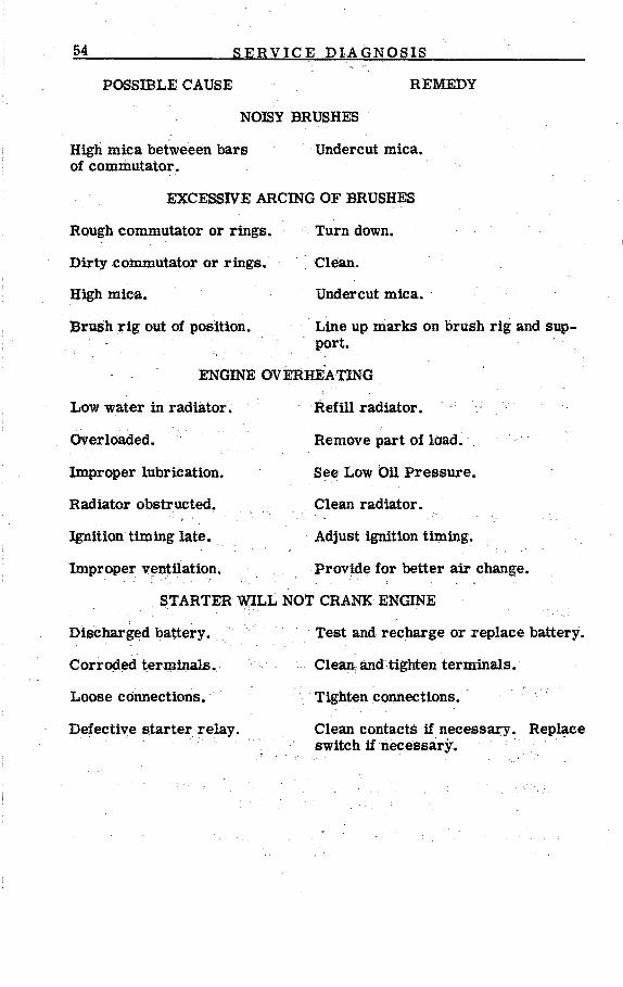
Service Diagnosis Possible Cause - Remedy bull bullbullbullbull bullbullbullbullbullbullbullbullbull47
Generator fj fj Ii ~ bull bull bull 39 Controls Regohm Voltage Regulator bullbull bull bull bull bull bull 43
Starting the Plant bullbullbullbullbull bullbullbull ~ bull ~ bull~ bullbull bull bull bull bull bull 44
m
IV
LIST OF ILLUSTRA TIONS
SUBJECT PAGE NO
Plant Name Plate bullbullbullbullbullbull bull bull bull bull bull bull bull bull 1
Reservoir Tank 6
Starter Cable Connection bull bull bull bull bull bull 7
Load Wires - 230 V 3 Phase 3 Wire Plant bull bull bull bull bull bull bull bull bull bull 8
Load Wires - 120208 V3 Phase 4 Wire Plant bullbull bull bull 8
Remote Control Connections bullbullbullbullbullbullbullbullbull bullbullbullbullbullbullbullbullbull-bull ~ 9
Ignition Timing bullbullbullbullbullbullbullbullbullbullbullbullbullbullbullbull ~ bull bull bull bull bull bull bull bull bull bull bull bull bull bullbull 37
Lubrication Chart bullbullbullbullbullbull ~ bull bull bull bull bull bull bull bull bull bull bull bull bull bull bull bull bull bull bull bull bull bull bull 22
Gasoline Carburetor Adjustment bullbullbullbullbullbullbullbullbull ~ ~ bull bull bullbull bull bullbull 27
Electric Choke bullbullbull bull bull bull bull bull bull bull bull bull bull 28
Counterweighted Choke - Gas Fuel bull bull bull bull bull bull bull bull bull bull bullbull bull bull 29
Gas Fuel Carburetor bull bull bull bullbull bull bull bull bull bullbull bull bull bull bull bull bull bull bull bull bull bull bull bull bull 30
High Water Temperature Cut Off Switch bull ~ bull bull bull bull bull bull bull 30
Governor Adjustment bull bull bull bull bull bull bull bull bull bull bull bull bull bull bullbull 31
Regohm Regulator Adjustment bullbullbull bull bullbull bull bullbull bullbull bullbull bullbull bull bullbullbull bull 34
Valve Rotors - Timing Gearsbullbullbullbull bullbullbull bull bull bull bull bullbull 36
Generator Maintenance bull bull bull bull bull bull bull bull bull bull bull bull bullbull bull bull bull bull bull bull bull bull bullbull 39
Generator Assembly bullbullbullbull bull bull bull bull bull bull bull bull bull bull bull bull bull bull bull bull bull bull bull bull bull bull bull bull bull 40
Brush Spring Removal bullbull bull bull bull bull bull bull bull bull bull bull bull bull bull bull bullbull bull 41
1 DESCRIPT]ON
INTRODUCTION
This instruction manual ismiddot supplied to assist in the proper installation operationmiddot and servicing of the Continental Engine Model R602 of the HR series of electric generating plants Unless otherwise indicated these instructions apply to all standard plants of the HR series Some details of these instructions may not apply to speCial models having modificashytions specified by the purchaser The use of auxUiary or special equipshyment special installation reqUirements or unusual operating conditions may require some deviation from these instructions However by using the instructions and recommendations given in this manual as a general guide it will be possible to make a goodinstallation and to properly operate and maintain the plant
Each electric generating plant is given an actual runniIig test and is careshyfully checked under various electrical load conditions before leaving the factory to assure that it is free of defe~ts and will produce its rated output Inspect the plant carefully for any damage which might have occurred in shipment Any part so damaged must be repaired or re placed before putting the plant in operation
If it should become necessary to contact the factory oran Authorized Service Station in regard to this generating plantalwaysgivetheModel and Spec Number and Serial Number as shown on the plantnanieplate This information is essential in order to properly identify the plant so that proper advice can be supplied
F~G 1 - ELECTRIC PLANT NAMEPLATEmiddot
2 DESCRIPTION
Basic differences in the HR series of plants are indicated by a letter A B etc ending the model number as given on the plant nameplate
The plant is a complete electric power plant consisting of an internal combustion engine a self exciteltf~le~tric generator directly connected to the engine and a control and tii~trument panel The engine end of the plant is designated as the frohtenQjCand right and left sides are determined when facing the front~~e
~~J _ENGINE
~~t
The engine is a Continental Mod~lR6026-cylinder over-head-valve enshygine It is a water cooled 4 stroke cyCle Full length water jackets around each cylinder in conjunction with a high velocity flow of coolshyant contribute to efficient engine cooling Full pressure lubrication with a shunt type oil iilter contributes to long engine life
ENGINE DATA
Cylinder Bore (Inches) 4-78 Piston Stroke (Inches) 5-38 Piston Displacement 602 cu in Compression Ratio 60 to 1 Piston - 5 ring hard Chrome plated top ring Connecting Rod Bearings - Replaceable precision type Main Bearings - Replaceable precision type Valves - Overhead rotating type Tappets - Adjustable push rod clearance Lubrication - Capacity 18 quarts dry - replaceable cartridge
Shunt type oil filter Cooling Capacity 64 quarts Ignition 12 volt battery - Firlng order 1-5-3-6-2-4- Neg Grd
GENERATOR DETAILS
The air cooled generator has two main components the alternator and the exc iter
The alternator is a revolving field type alternating current generator The generator rotor is connected directly to the engine flywheel and turns at enginespeed The rotor is a four pole type and must operate at approximately 1800 rpm for the 60 cycle plants The alternating curshyrent is generated in the stator winding of the alternator and is taken to the AC output terminals inside theII1etal box on the generator The outshyboard end of the rotor is supported by a lubricated ball bearing The stator end bell casting whiCh might be called an adapter bell to distinshyguish it from the exciter end bell houses this stator bearing as well as the sUp ring brush rig which serves to feed exciter current through
3 DESCRIPTION
the rotor Hand holesin the adapter bell provide access to the slip ring brushes and to the constant-pressure type brush springs for sershyvicing
The separate exciter is a stationary field direct current generator The output of the exciter is used to create a magnetic field in the rotor The exciter armature shaft is tapered and keyed to the outboard end of the rotor shaft
The generator is specifically designed for high efficiencyand excellent motor starting ability The external voltage regulator gives extremely close (2) voltage reglation The manually operated field rheostat may be used to control voltage for emergency operation if the automatic regshyulator should fail The frequency of the current is determined by the engine speed and is regulated by the engine governor The output rating is at 08 (80) power factor load The rated capacity for 60 cycle plants is 75000 watts (75KW)~The rated capacity for 50 cycle plants is reduced to 60KW due to lower engine speed
CONTROLS
The control box located at the rear of the plant mounts engine operatshying instruments and electrical meters etc according to the particular model The engine instruments for the standard plant include electric water temperature gauge electric oil pressure gauge battery charge rate ammeter start-stop switch Safety devices include a high water ternperature cut-off and a low oil pressure cut-off switch The comshyplete electric instrument panel for housed units includes a running time meter ammeter AC volt meter DC volt meter phase selector switch circuit breaker frequency meter voltage regulator rheostat and manual voltage control rheostat
4 OPTIONAL EQUIPMENT
DAY If FUEL RESERVOIR TANK The DAY fuel reservoir tank proshyvides a reservoir of gasoline fuel
which feeds by gravity to the carburetor Gasoline tends to slowly evaporate from the carburetor during shut-down periods If the shutshydown is of lengthy duration such as in standby service the evaporation may be enough to prevent ready starting The )A Y tank keeps the carburetor full for an extended time thus insuring against starting failure due to a partially filled carburetor
LINE TRANSFER - A complete line of automatic line transfer controls are available designed especially for standby sershy
vice Upon faUure of the regular source of electric power the line transfer disconnects the load lines from the regular power supply lines starts the llant and connects the load lines to the plant The plant continues to run regardless if electrical load is connected or not unshytil the regular power supply is repoundgttored When power is restored the line transfer then disconnects the load lines from the plant stops the plant and connects the load lines back to the regular power supply lines
UNDERGROUND FUEL TANK - Fuel tanks of 55 110 or 250 gallon capacity are available for underground
use Fill and vent pipes and a suction tube extending to within an inch or two of the tank bottom are supplied Provision formiddot a fuel return line connection (necessary when DAY reservoir tank ls used) is also proshyvided
5
middot I
INSTALLATION
LOCATION If the generating plant is to be installed in a permanent location choose a site for the plant that will be more or
less centrally located in relation to the electrical load Plan to avoid running wiring for a long distance For standby installations the usual location is close to the main fuse or entrance box Check local regulashytions concerning standby installations
The selected site for the plant should be in a clean dry well ventilated location preferably heated in extremely cold weather Choice of either a damp or exceptionally dusty location will require more frequent in spectionand servicing of the plant
MOUNTING The plant should be mounted on a raised concrete or heavy timber case for ease in draining oil and other
periodic servicing Allow at least 24 inches clearance space on all sides of the plant for access in serviCing Though not a requirement for pershymanent installations the plant may be bolted down if desired
If the plant is to be used for mobile service mounted in a truck or traishyler it must be bolted securely in place so that it can not shift while in transit Make provisions for access to the plant for servicing Extra support for the vehicle floor maybe necessary to prevent the mounting bolts from tearing loose on rough roads or in turning sharp corners
VENTILATION The plant creates a considerable amount of heat which must be removed by proper ventilation In a large
room or outdoors cooling will be no problem However if the plant is ihstalled inside a small room or compartment provide separate air inlet and outlet openings
Cooling air travels from the rear of the plant towards the front endmiddot Locate the compartment air inlet opening where most convenient preshyferably to the rear of the plant The inlet opening should be at least as large as the radiator area
Engine heat is blown out through the front of the plant by a pusher type fan The cooling air outlet should be directly in front of the radiator and as close as is praCticable The opening should beat least as large as the radiator area preferable larger Where the opening size must be held to the minimum a duct of canvas or sheet metal may be used between the radiator grill on the plant and the compartment air outlet The duct will prevent recirculation of heated air
Generator cooling air is drawn in at the rear end and discharged at the bottom forward end of the generator The heated air is then picked up and discharged through the engine radiator
In cold weather a means of restricting the air flow can be provided to keep the compartment temperature at a normal point
6 INST A L LA TION
EXHAUST - The engine exhaust gases are deadly poisonous and must be piped outside any room or other enclosure Use pipe
as large as the exhaust connection on the engine Use pipe at least as large as the muffler outlet for the first ten feet Increase the size of the pipe one pipe size for each tenfeet of additional length Avoid the use of 90 degree pipe elbows if turns are necessary as they tend to create undesirable back pressure in the exhaust line
Insulate or shield the exhaust pipe if there is danger of anyone touching it or if it must be run close to any wall or other material that is not completely fire proof If the exhaust line must pass through a combusshytible wall or partition proviqe insulated shield collars for the line The wall openings must be at least 4 inches larger on all sides than the exhaust line
FUEL SUPPLY GASOLINE - When an underground fuel tank is inshystalled the total lift of fuel from tank
to fuel pump inlet should not be more than 6 feet The horizontal disshytance between the tank and plant should not be more than 50 feet Most fuel tanks for underground use have the fuel outlet at the tank top reshyquiring a drop or suction tube extending down to within an inch or two of the tank bottom All fuel line connections between the tank and the plant fuel pump must be air tight Any air leak will prevent pumping of fuel to the plant The fuel pump inlet opening is threaded for 14 pipe A proper adapter fitting must be used if other than 14 pipe thread fitting is used on the fuel line A priming lever is attached to the fuel pump
DAY FUEL RESERVOm TANK - In standby serVice the generating plant may stand unused for many
days In this period of shut-down sufficient gasoline may evaporate from the carburetor to lower its fuel level considerably Prolonged cranking may then be necessary to pump enough gasoline into t~e car-
VENT LINE TO EXTERIOR OF VILOING
7ESERVOIR TANKshy(MOUNT IN CONVENIENT PLIICE ON PLANT)
LINE FROM FUEL PUMP
RETURN LINE TO UNPERGROUND
shyFUEL TANK =---1LAIGE
LINE TO CARBVRETOR
FIG 2 - DAY TANK INSTALLATION
7 INSTALLATION
buretor for the engine to start Where automatic unattended starting after extended shut-down is necessary an auxiliary gravity feed fuel tank should be installed Fuel from this tank flows by gravity to the carshyburetor thus replacing any fueUost through evaporation and promotes quick starting after an idle period Note that a large fuel return line must be provided between the auxiliary tank and the main supply tank
FUEL NATURAL GAS OR LPG - If the plant is equipped for the use of natural gas (or LPG) connect the
gas fuel line to the gas pressure regulator as shown in Figure 00 The position of the gas pressure regulator 1s important and it must be inshystalled as shown in the illustration Local regulations may require the installation of a fuel solenoid valve and filter
BAlTERY CONNECTION - Cables for making connections between the plant and the battery are supplied with all
plants even though the starting batteries are not If necessary spread the cable lug open slightly ~ Do not use a hammer to drive the cable lugs onto thE) battery terminal posts because the battery may become damaged Cable lugs should make clean full contact on the battery tershyminal posts to prevent loss of current at this point Coat lugs and tershyminal posts with a thin coating of vaseline to help prevent corrosion
If a single 12 volt battery Is used connect the long battery cable with the larger lug from the positive (+) post on the battery to the outside terminal on the starter Connect the other long cable from the negative (-) post on the battery to the starter mounting stud as illustrated The short jumper cable is not used with a single 12 volt battery Secure cable connections at all points
TO NEGATIVE POST
If two 6-volt batteries are to be connected in ON SA rTERY series to form a 12-volt battery connect the II 1gt
short jumper cable from the negative (-) post of one battery to the posi~ive (+) post of the second battery Then make the longer cable connections as described in the foregoing par agraph
-TO Batteries should always be installed on a POSITIVE POST
ON8ATTERVwooden or metal rack to permit a free cir shyculation of air around the battery FIG 3middot - STARTER
CONNECTING THE LOAD WffiES - Connect the AC load wires to the terminal lugs inside the sheet
metal box on the generator Observe electricalcode specifications Be sure to provide a switch for disconnecting all electrical load from the plant Connect the load line wires to the terminal lugs according to the following directions depending upon the type of plant Properly fuse each circuit
8 INSTALLATION
230 VOLT 3 PHASE 3 WffiE PLANT
No terminal is grolIDded For three phase current connect separate load wires to each plant terminal 11 12 13 one wire to each terminal Reversing the connections between any two terminals will reverse the direction of rotation of 3 phase motors If phase sequence is important
~ 1 ~
~ Ci
~ So I
~ 1 ~
~ ti L
~ fI
as when paralleling plants be sure to check the phase sequence before connections are completed
To obtain 230 volt Single phase current connect sepshyarate load wires to each of any two plant terminals Three 230 volt single phase circuits are thus available with not more than 13 of the plant rated capacity for each circuit Balance the load as closely as possible among the circuits
If both single phase and three phase current is to be used at the same time use care not to overload any one circuit Subtract the amount of the 3 phase load from the rated capacity of the plant Divide thereshymainder by 3 and this is the maximum load that can be taken from anyone circuit for single phase current use For example a 75000 watt plant is used with a 45 000 watt 3 phase load connected This leaves 30 000 watts available for single phase use Divide the 30 000 watts-by 3 giving 10 000 watts available on each single phase circuit Do not attempt to take all 30000 watts off one circuit distribute the load equally over the three single phase circuits
120 VOLT SINGLE PHASE208 VOLT THREE PHASE PLANT
The terminal marked TO is grounded For 120 volt single phase current connect the neutral (white) load wire to the TO terminal Connect the hot (black) load wire to anyone of the other three terminals I1ft 12 or 13 Three separate 120 volt single phase circuits are thus available Do not attempt to take more than 13 the rated capacity of the plant from anyone circuit Balance the load as closely as posshysible among the three circuits
For 208 volt three phase current connect~a separate load wire to each of the plant terminals 11 12 and 13 leaving the TO terminal unused Reversshying the connections between any two terminals will reshyverse the direction of rotation of 3 phase motors If phase sequence is important as when par8Jleling plants check the phase sequence before making final connecshytions
9 INSTALLATION
For 208 volt single phase current connect separate load wires to each of any two terminals Tl If T2 or T3 Do not use the ff1O tershyminal Three separate single phase circuits are available tT1 tt and T2 Tl tt and T3 T2tt and T3 Do not attempt to take more than 13 the rated capacity of the plant from anyone circuit Balance the load as closely as possible among the three circuits
If both single and three phase current are used at the same time fol low the prinCiples of load distribution as given for the 3 phase 3 wire plant
460 VOLT or 575 VOLT 3 PHASE 3 WIRE PLANT
Follow the prinCiples of connection as given for the 230 volt 3 phase 3 wire plant
120240 VOLT or 220380 VOLT 3 PHASE 4 WIRE
Follow the prinCiples of connection as given for the 120 volt Single phase208 volt 3 phase 4 wire plant
REMOTE CONTROL CONNECTIONS - A small 4 place terminal marked REMOTE-DC OUTPUT is
located inside the control box If automatic or line failure controls are to be connected follow the directions for connections as supplied with the control eqUipment The terminal block is marked B+ 123 tt
RSMorE CONTROl TERMshyINAl BLOCK AT PIANT
( ~ TWO STVLES OF MOMENTARY CONTACT SWITCH
FIG 5 - REMOTE CONTROL CONNECTIONS
Connect the remote control switch to the terminal block on the plant by running a wire from ttOFFtt on the switch to 2 terminal on the block Connect ONtt to 3 on the block The remaining wire is to be run from the last vacant term~nal on the switch to 1 on the terminal block
A remote control switch is supplied with the remote starting type plant This switch and additional switches may be installed at convenient points
10 INSTALLATION
The wire length from the plant to the switch determines the wire size necessary Use 18 wire up to 85 feet 16 wire up to 135 feet 14 wire up to 215 feet and 12 wire up to 350 feet
AUTOMATIC CONTROLS - Separately mounted automatic controls can be connected to the generating plant Beshy
fore buying and installing such a control the purpose should be analyz~d in order to select the correct type desired One type of control serves to start and stop the plant according to load demand where there is no commercial power Another type of control starts and stops the plant and transfers the load during an interruption of commercial power Automatic controls should be used when even a short interruption of comshymercial power is serious or in locations where there is no attendant to throw a hand-operated switch These controls serve various other funcshytions and literature and advice covering the particular application should he requested from D W ONAN amp SONS or any of its Authorized Distributors Dealers or Parts and Service Centers
11 PREPARATION
CRANKCASE OIL - The oil capacity of the crankcase when dry (oil filters empty) is 18 U S quarts The dry oil
filters take 4 quarts of oil Select the proper SAE number of oil accordshying to the lowest expected temperature Use detergent oil classified by the American Petroleum Institute as Service DG or as marketed by most manufacturers MSDG
The use of Service tl)S is satisfactory but its higher cost is not justishyfied
TEMPERATURE SAE NUMBER
Above 500 F 200F to 500F
00F to 200 F
40 30 20W
The use of a heavy duty (detergent oU keeps dirt and sludge particles in suspension so that they are removed when the oil is drained and the filshyter is changed
NOTE
When adding oil between changes always use oil of the same brand When mixed together detergent oils of different manshyufacturers sometimes form chemical compounds harmful to engine parts
TO CHECK THE OIL - Shut the engine off and allow it to stand for 2 minutes This will allow the oil to drain down
from the valve chamber The oil reading on the bayonet gauge will show the oil level
If the ollievel reads at the lower mark on the bayonet gauge add oil to bring the reading to the top mark
If the engine stands for any length of time the oil level will read about 2 above the top mark This is normal as the oil has drained down from tne filters
AIR CLEANER - Remove the air cleaner bottom and fill the reservoir cup to the disk indicated on the cup bottom with oil
of the same SAEnumber as used in the crankcase Be sure to lock the cup in place when replacing
RADIA TOR - The capacity of the cooling system is 64 quarts (U S measure) Check to see that the radiator drain and the
cylinder block drain are closed Fill the radiator to within an inch or two of the bottom of the filler neck Use cleansoft (alkali free) water such as clean rain water The use ofa good rust and scale inhibitor is recommended
middot12 PREPARATION
If the plant will be middotexposed to freezing- temperatures (below 320 F or 00
C) use a standard anti-freeze solutionbull Use the correct proportion of anti-freeze as recommended by the anti-freeze manufacturer to proshytect at least 10 degrees F below the lowest expected temperature
FUEL GASOLINE - Use fresh regularttgrade of gasoline Do not use a highly leaded premium grade of gasoline
The use of highly leaded gasoline will require more frequent lead reshy moval valve and spark plug servicing The engine is designed to operate at highest efficiency and economy when using regular ll grade gasoline However do not use a low octane fuel such as lIstove gas The use of such fuel may cause serious damage to the engine
FUEL NATURAL GAS - Follow national and local codes on installing luelpipes Be sure thatall connections are
leak proof
The secondary regulator requires a line pressure from 4-6 ounces If the line pressure is more than 6 ounces a primary regulator must be installed in the line to reduce the pressure before it enters the secondary regulator
In some localities presence of a foreign matter in the fuelmayxequire the installation ofa trapor filter in the line Consultthefue1snpplier
13 OPERATION
GENERAL - Before putting the plant into operation for the first time1
be sure that it has been properly installed and that all requirements under PREPARA TION have been met Check the following points
1 See that no electrical load is connected to the generator (throw the circuit breaker to the OFF position)
2 See that the VOLTAGE REGULATOR RHEOSTAT knob is at its approximate perpendicular or mid-adjustment point
3 See that the FIELD RHEOSTAT AND VOLTAGE REGULATOR SWITCH knob is at its extreme COUNTERCLOCKWISE position
STARTING THE PLANT For electric starting press the START-middot STOP toggle switch in the START direcshy
tion holding in contact to crank the engine On the initial start or if the plant has run out of fuel extensive cranking may be necessary to pump fuel to the carburetor and fill it The carburetor is automatically choked and as soon as the carburetor is suffiCiently full the plant should start As the engine begins to fire hold the START switch in contact until running speed has been reached
Inhibitor oil was sprayed into the cylinders after the factory test run and it may be necessary to remove the spark plugs and clean them with gasoline before the plant will start the first time Dry the plugs thorshyoughly before reinstalling them
If gas fuel is used the carburetor choke must be adjusted as described under the paragraph Carburetor-Gas On the initial start it will probshyably be necessary to press the priming button on the gas pressure regshyulator momentarily Do not overllrime
CHECKING OPERATION - After the plant starts check the engine inshy struments immediately See that all are
indicating normally as outlined below On the initial run allow the plant to reach operating temperature then check the coolant level in the radiator The thermostat may have permitted an air pocket to form thus preventing complete filling
NOTE
Inhibitor oil was sprayed inside the cylinders after the factory test run On the initial run there will be a considerable amount of smoke in the exhaust gases until the inhibitor oil is burned out
OPERATION
Throw the circuit breaker handle to the ON position to connect electri~ cal load to the plant If the plant tends to surge slightly it is usually an indication that additional warm up is needed before connecting a heavy load Continued surging after warm up indicates needed adjustments of the carburetor or governor Refer to the ADJUSTMENT section
The engine instruments are furnished on all standard plants Their function and normal readings or positions are as follows
OIL - The oil pressure gauge registers the engine oil pressure while the engine is running Normal operating pressure
is 40 to 60 lbs at operating temperature some what higher until the plant warms up
TEMPERA TURE The water temperature gauge registers the coolant temperature during operation Normal
operating temperature is 1500 to 1700 bull
AMPS- Ihe ammeter indicates the battery charge or discharge current in amperes The rate of charge during operation
depends upon the charge condition of the battery Under normal conshyditions the charge rate will be 5 to 10 amperes when the plant starts The rate will gradually fall to almost zero as the battery becomes fully charged
EMERGENCY STOP RELAY -The stop relay button must be pushed to de-energize the stop relay when
one of the safety devices has operated to stop the plant lnvestigate the cause jor the emergency stop before again starting the plant
STARI-STOP - Ihe start-stop switch is a normally open momenshytary contact switch Push the switch up to start
and down to stop the plant
SAFETY STOPPING DEVICES - The HR series plants are equipped with two safety devices which opshy
erate to stop the plant under certain conditions which could cause serious damage
1 High Water Temperature Cut-Off - The temperature cut off is a thermostatic type
switchmounted on the engine which acts to stop the plant if the coolant temperature rises too high A dial adjustment permits setting the switch for various temperatures Refer to ADJUSTshyMENTs
2 Low Oil Pressure Cut-Off - The oil pressure cut-off is a pressure operated switch
mounted on the engine which acts to stop the plant if the aU presmiddot
15 OPERATION
sure drops to less than 9 pounds It is not adjustable The low oil pressure cut-off switch is Optional Equipment (NOTE When the plant is equipped with a low oil pressure cut-off switch a time delay relay is also furnished The time delay relay is used as a pilot relay which is in series with the ground lead between the low oil pressure cut-off switch and the Emergency Stop Relay The time delay relay does not close its contacts until approxishymately 5 seconds after energization of its coil thus allowing the engine oil pressure to build up and open the grounding connection of the low oil pressure cut-off switch)
If one of the safety dev~ces has operated to stop the plant it is necessary to press the EMERGENCY STOP RELAY reset button before the plant can be started again in a normal manner
The electrical meters and controls vary with the different models Their description and normalfunction are as follows
RUNNING TIME The running time meter registers the number of hours to 110th that the plant has actually run
It provides a convenient means of ke~ping a regular servicingschedshyule
VOLTS - The voltmeter indicates the a c voltage of the generator circuit On three phase models voltage of one phase only
as determined by the selector switch position will be shown On four wire three phase models only the three phase voltage (higher nameplate rating) will be shown
CIRCUIT BREAKER - The circuit breaker is a safety device bull In case of a severe over-load the circuit breaker
will automatically trip to the OFF position disconneCting the load terminals from the generator output When the circuit breaker handle is at the ON pOSition the load terminals are connected to the genshyerator output The circuit breaker can be used as a manual connectshydisconnect switch
SELECTOR SWITCH ~ The selector switch is provided on three phase models only Its setting determines which
phase of the generator circuit is indicated on the ammeter and voltshymeter
OP ERATION
REGULATOR RHEOSTAT - The voltage regulator rheostat position determines the REGULA TED voltage
Normal setting is with the arrow on the knob pointing straight up
COMBINATION FIELD RHEOSTAT AND VOLTAGE REGULATOR SWITCH - The field rheostat is provided for EMERGENCY use only
in case of failure of the voltage regulator Normal set ting of the knob is extreme counterclockwise When turned slightly clockwise the voltage regulator is disconnected and voltage MUST be manually controlled
ENGINE CONTROL OPERATION - A brief description of the function of the various engine control cir shy
cuits will enable the operator to more easily understand their operation
When the Start Button is pushed to start pOSition battery current is fed to the Start Solenoid Relay its contacts close and feed battery current to the Start Solenoid its contacts close and feed battery current to the Starting Motor which cranks the engine The Start-Disconnect relay which is in the cranking circuit opens its contacts and disconnects the cranking circuit when it becomes energized by the charging generator Voltage as the charging generator comes up to speed
When the Start -Sutton is pushed the Start Ignition Relay is energized connecting the battery across the ignition circuit As soon as the batshytery charging generator comes up to speed as the engine is cranking enough voltage is generated to close the Ignition Relay (Labeled Stop Relay on the Wiring Diagram)~ The ignition relay remains operated as long as the plant is operating To stop the plant operation of the Stop Push Button grounds the coil of the Ignition Relay disconnects the igshynition circuit and stops the plant
The ignition circuit goes thru the normally closed contact of the Emershygency Stop Relay If either high water temperature or low oil pressure occurs the Emergency Stop Relay coil connected to the charging genshyerator becomes eqergizedmiddot disconnects the ignition circuit and stops the plant (This also occurs if the plant is equipped with a low oil presshysure cut-off switch) When the Emergency Stop Relay is energized the normally open contacts close connecting the hold in coil circuit to the battery positive When this occurs the cause of the plant shut-down should be determined first before attempting to start the plant again Whenever the Emergency Stop Relay has operated the Emergency Reshyset Switch must be operated before the plant can be started
When the start button is pushed to start position the Anti~Dieseling Solenoid Start Relay is energized its contacts close feeding current to the Anti-Dieseling Solenoid The energized solenoid pulls the plunger inwhich in turn opens the butterfly valve in the carburetor The AntishyDieseling Solenoid will remain in operation as long as the unit is runshy
17 OPERATION
ning When the stop button is pushed to stop the Anti-Dieseling Soleshynoidbecomes de-energized A spring attached to the solenoid plunger pulls the plunger out which closes the butterfly valve thus shutting off the air supply to the cylinders and prevents dieseling from taking place
STANDBY SERVICE - Whenthe plant is used for standby service (fallshyure of a commercial or other regular source of
power) it is essential to exercise the plant regularly If practicable start and run the plant for approximately 15 minutes every day or two lf a fuel reservoir tank (see INSTALLATION)isused the length of time between exercise periods can be considerably lengthened However an exercise run at least once a week is recommended
VOLTAGE REGULATOR bull - Normally the voltage regulator does not reshy quire attention during successive operating
periods The voltage regulator is an automatic device for controlling the output voltage of the generator Its action provides the same effect as is obtained by hand operation of arheostat on a manually controlled generator
The voltage regulator knob pOSition determines the regUlated voltage of the generator output The regulator was adjusted at the factory to give the rated voltage with the knob arrow pointing straight up The voltage can be lowered or raised approximately 10 by turning the adjusting knobbullTurn counterclockwise to lower the voltage or clockwise to raise the voltage The regulator will keep the voltage at its set value regardshyless of changes in temperature load or power factor If the voltage can not be set at the desired point by knob adjustment a change in the regulator resistor setting may be required Refer to ADJUSTMENTS
FIELD RHEOSTAT -The field rheostat provides for manual control of output voltage andmiddot should be used ONLY in case
of Voltage regulator failure When the FIELD RHEOSTAT knob is turned to its normal extreme counterclockwise pOSition middotan integral switch proshyvidesfor automatic voltage regulator operation However turning the FIELD RHEOSTAT knob slightly clockwise disconnects the autollatic voltage regulator and the generator voltage MUST be manually controlled by knob operation
When manual voltage control is necessary turn the FIELD RHEOSTAT knob from its extreme counterclockwise position just enough to cause the integral switch to cut out the regulator Start the plant and adjust the rheostat knob to obtain the proper voltage
The voltage of the generator will drop somewhat as it warms up necesshysitating a rheostat adjustment The rheostat setting must also be changshyed as the electrical load on the generator is changed to keep the voltage at a safe operating point As electrical load is increased the voltage will drop and it will be necessary to turn the rheostat knob clockwise
18 OPERATION
to raise the voltage back to normal Likewise as electrical load is reshymoved the voltage will rise and a counterclockwise adjustment of the rheostat knob is necessary to lower the voltage Keep in mind that any substantial change in the amount of load connected to the generator calls for a compensating readjustment of the rheostat knob
STOPPING THE PLANT - The plant is stopped by pushing the control panel switch or a remote control switch to
the STOP position If practicable disconnect all load before stopping the plant
19
ABNORMAL QPERATING CONDITIONS
LOW TEMPERATURES
CRANKCASE OIL - For cold weather operation select the SAE number of the crankcase oilaccording to the lowest tern ~
perature expected before the next scheduled oil change See PREPARAshyTION When changing to a lighter oil for cold weather change the oil filter elements at the same time After changing to a lighter oil alshyways run the plant for a few minutes to circulate the lighter oil through the engine
If an unexpected temperature drop takes place use caution in attemptshying to start the plant after a shut down period Do not attempt to start a plant that is so ~stiffn that it will not crank properly Congealed oil may not flow readily resulting in lack of lubrication to vital parts and causing serious damage In an emergency apply heat directly to the engine oil pan to warm the oil When the oil is sufficiently fluid start the plant and allow it to thoroughly warm up stop the plant and change the oil (and oil filter elements) to the proper SAE number
RADIATOR - If there is a possibility of the temperature falling below 320F (OoC) the coolant must be protected against freezshy
ing Use a good anti-freeze compound in the proportion recommended by the anti-freeze manufacturer protecting to at least 10 degrees F below the lowest expected temperature The capacity of the cooling system is approximately 64 US quarts
Set the high water temperature cut-off switch (See ADJUSTMENTS) to operate ata temperature several degreeS below the boiling point of the anti-freeze solution used taking into consideration thEiaJtitude at which the plant is operating
If the cooling system is drained to prevent freezing be sure to remove the radiator cap while draining Failure torelllove the cap may form a vacuum in the cooling systempreventing complete draining Besure that the cylinder block drain cock is fully opened for complete draining of the radiator
GASOLINE FUEL - Use fresh cleanwinter grade (not highly leaded premium) gasoline for best starting in cold weather
If the fuel talik is subject to considerable temperature variations keep the tank nearly full in order to cut down condensation of moistureinside the fuel tank Such condensation call cause trouble by ice formation in the fuel system Avoid filling thetalik entirely full of cold gasoline Expansion of the fuel as it warms up may cause it to overflow llndGreate a fire hazardmiddot
GAS FUEL Certain tYpes of LPG fuef do not vaporizereailily at low temperatilres~ Heat exchanger equiprnenfmay be necesshy
sary Consult the fuel supplier if lowered performance is observ~at low temperatures
20 ABNORMAL OPERATING CONDITIONS
BATTERY - Check the charge condition of the starting battery often enough to assure that it is always in a well charged conshy
dition The charging circuit is designed to keep the battery well charged in normal service but frequent starting with short operating periods may cause the charge condition to drop to a pOintwhere there will not be enough power to crank the engine at low temperatures~
The cranking power of a battery drops to about 40 of its normal power at OOF and the cranking load is greatly increased If practicable reshymove the battery to a warm place during shut down periods in extremely cold weather It takes but a few minutes to connect the battery for start shying and its cranking power will be much greater ifmiddot warm
IGNITION - The ignition system must be in good condition for prompt starting in cold weather The distributor breaker points
and condenser and the spark plugs are particularly important See that the breaker pOints are in good condition (not burned or pitted) and are properly adjusted
HIGH TEMPERATURES
LUBRICATION - As indicated under PREPARATION use SAE No 40 oil for temperatures above500 F Keep the oil level
at or near the FULL mark on the level indicatorbull However do not over fill the crankcase Use the same SAE number oil to service the air cleaner
COOLING - A constant supply of fresh air must be provided for proper cooling See that nothing obstructs the flow of air to the
plant and see that the radiator air outlet flow is not obstructed in any way Keep the radiator well filled Use a good rust inhibitor to keep the cooling system clean and free of rust and scale formation See that the fan belt tension is properly adjusted Be sure the high water temshyperature switch is properly adjusted (see ADJUSTMENTS)
BATTERY - Check the level of theelectrcilyte frequently Add approved water as often as necessary to keep the level at the point
recommended by the battery manufacturer
NOTE
REDUCING BATTERY SPECIFIC GRAVITY FOR LONGER BATTERY LIFE
Standard automotive type storage batteries wUl self discharge very quickly when installed where the ambient temperature is always above 900 F such as in a boiler room or in tropical climates To lengthen battery life dilute the electrolyte from a normal 1 275 specific gravity reading at full charge to a 1 225 reading
21 ABNORMAL OPERATING CONDITIONS
The cranking power of the battery is reduced somewhat when the eledrolyte is diluted but if the temperature is consistently above 900 F the reduced cranking power will hardly be noticed and lengthened battery life will be a distinct advantage Adjust the electrolyte as follows
1 Fully charge the battery Do not bring an open flame or burning cigarette near the battery during charging as the gas released during charging is highly inflammable
2 While the battery is still on charge use a hydrometer or filler bulb to draw off aU the electrolyte above the plates in each cell DO NOT ATTEMPT TO POUR OFF Avoid skin or clothing contact with the electrolyte Dispose of the removed electrolyte
3 Refill each cell with pure distilled water to the recommended level
4 Continue charging for one hour at a 4 to 6 ampere rate
5 Use a reliable hydrometer to test each battery cell If the specishyfic gravity is still above 1 225 repeat steps 23 and 4 until the reading of the fully charged battery is not over 1 225 Most batshyteries require repeating steps 2 3 and 4 two times
DUST ANDDmT
Am CLEANER - Clean the air cleaner and change its oil as frequently asthe conditions require The air cleaner function
of trapping air borne dust and dirt is very importantin promoting longer engine life
RADIATOR - Keep the radiator cooling fins clean and free of dust chaff leaves etc Clogged cooling fins will reduce the
effective cooling area of the radiator and may result in improper cooling
GENERAL - Keep the entire plant as clean as practicable Wipeoff accumulations of dust dirt and spilled oil Keep the
generator commutator slip rings and brushes clean Keep supplies of fuel and oil in air tight containers Change the crankcase oil and the oil filter elements more frequently as conditions require
22 PERIODIC SERVICE
Follow a definite schedule of inspection and servicing to assure the best performance and long life of the plant Service periods outlined below are for average service and normal operating conditions Under unshyusual service or abnormal operating conditions service the plant more frequently Keep a record of the hours the plant is operated each day to assure servicing at the proper time
Oil level Coolant Air cleaner cup and filter Crankcase vent cap Battery electrolyte level Oil-charge generator start motor~ Change engine oil Change oil filter element Lubricate distributor Inspect and adjust points Fan belt tension Clean spark plugsmiddot Magneto pOints Compression pressure AC-DC generator brushes Charging generator brushes Tappet clearance Starting motor brushes Inspect commutator Grind valves Clean carbon Remove and clean oil pan and oil pump inlet screen Flush cooling system AC-DC generator bearing Clean carburetor 0 Complete reconditioning
-Replace as Required o - Service as Required
HOURS OF OPERATION
Daily 50 100 200 500 1000 X X X
X X
X X X X X X X
X
it X X X X
X
X X x
5000 Hours
If it is necessary to remove parts for inspection and gaskets are disturbed they should be replaced with new ones
When brushes are replaced be sure the commutator and slip rings are in good condition
RecommendedFuel Use a regular grade of gasoline If a high lead conshytent is used it will be necessary to remove the lead
deposits more frequently
23 PERIODIC SERVICE
GENERAL - Follow a definite schedule of inspection and servicing to help in keepingthe plant in good running condition and to
keep operating expenses to a minimum Service periods outlined in this section are for normal service and operating conditions For extreme conditions such as continuous heavy duty extremely high or low temshyperatures etc service more frequently For periods of littlE use
service periods can be lengthened accordingly Keep a record of the operaUng hours each day to assure servicing at the proper intervals
DAILY SERVICE
If the plantis operated more than 8 hours daily perform the DAILY SERVICE operations every 8 hours
FUEL - If the plant is operated on gasoline fuel check the fuel supply often enough to avoid running out of fuel If the plant stops from
lack of fuel it will be necessary for the fuel pump to first pump enough fuel to the carburetor to permit starting again This may require conshysiderable cranking or working the primer leVer on the pump depending upon the distance of fuel lift from the tank to the fuel pump
CRANKCASE OIL - Check the oil level on the level indicator Donot allow the oil level to fall below the ADD OIL mark
on the indicator Add oil ofthe proper SAE number as necessary to bring the level to or near the FULL mark on the indicator Do not over fill
Am CLEANER - Service the air cleaner as often as required by the opshyerating conditions Under extremely dusty conditions
it may be necessary to clean the air cleaner and renew its oil several times during a days operation Under dust-free conditions every 100 hours or even less frequent servicing may be sufficient
To service the air cleaner remove the cup by turning it to the left Lift out the fin section in the cup then pour out the oil Wipe the reservoir cup clean and replace the fin section
Fill the cup to theraised button on the bottom of the fin section Reshyplace the cup to the air cleaner by lifting the cup upwards and turning to the right to lock it in place
RADIATOR - Check the level of the coolant in the radiator and add liquid as necessary to bring the level up to normal If
freezing weather prevails and a non-permanent type anti-freeze is used test the protective strength of the solution The high water temperature switch will not protect against evaporation
CLEANING - Keep the plant clean as practicable A clean plant is easier to service and will give better service Wipe off
spilled oil dust dirt etc
middot24 PERIODIC SERVIC E
WEEKLY SERVICE
If the plant is operated more than 50 hours a week perform the WEEKLY SERVICE operations every 50 hours
CRANKCASE OIL - With a new (or reconditioned) engine use SAE 20 oil for the FIRST 20 HOURS OF OPERATION
Drain and refill the crankcase again irlter the next 50 hours of operation If the plant is operating under temperature conditions of 320 F (OOC) or lower continue to change t~e crankcase oil at 50 hour intervals
CRANKCASE BREATHER - Remove the oil fill cap and clean in a good solvent Oil the wire mesh with engine oil
Under severe dust conditions service more frequently
OIL FILTERS - The oil filter is a shunt type and if allowed to becomemiddot filled with sludge to the point where no oil can flow
through it a by-pass valve opens to provide lubrication to the engine
Change the oil filter elements each time the oil is changed
Place a drip pan under the oil filter Remove the center bolt and remove the filter housing After discarding the dirty filter elementand gasket clean the metal parts with solvent making sure the racUal holes in the center bolt are not clogged Place a new gasket in the filter base recess Reshyplace the new element and cover and tighten the bolt Overtightening the center bolt may cause distortion of the filter housing and cause oil leakshyage Check for oil leakage after the engine has warmed up
GOVERNOR LINKAGE - Inspect the ball jOints of the governor llrm and carburetor throttle linkage Keep thele points
free of dust Lubricate with a dry type of lubricant such as powdered graphite If a dry lubricant is not obtainable use only a light machine oil of non-gumming quality
BATTERY GENERATOR- Has sealed bearings and does not require any lubrication
STARTER - The starting motor does not require lubrication
BATTERY - See that the battery connections are clean and tight bull Corshyrosion at the terminals can be removed by flushing with
a weak baking soda and water solution Flush clean with clear water and dry thoroughly A light coating of grease or asphalt paint on the battery terminals will retard such corrosion middot
25 PERIODIC SERVICE
Keep the electrolyte at the proper level above the plate separators by adding clean water which has been approved for use in batteries In freezing weather run the plant for at least 20 minutes after adding water
to mix the water with the electrolyte and prevent its freezing
SEMI-MONTHLY SERVICE
If the plant is operated more than 100 hours semi-monthly perform the following operations every 100 operating hours
FUEL SYSTEM -Remove the drain plug at the bottom of the carburetor to drain off any sediment Ilstall the plug securely
Remove the filter bowl and screenmiddotfrom the fuel pump clean thoroughly and replace After servicing is completed inspect carefully against leaks
SPARK PLUGS - Remove the spark plugs clean them and adjust the gap according to the dimensions given hi the TABLE
OF CLEARANCES Replace with a new one any plug which will not pass a standard compression firing test
DISTRIBUTOR - Examine the distributor breaker points If burned or pitted replace with a new set See that the point gap
is set at 0019 to 0021 at widest separation Apply a very small amount (about the size of a match head) of high temperature grease on the breaker cam surface Turn the grease J~up located on the side of the distributor one turn inward
COMPRESSION TEST - Use a compression gauge to test the engine compression Low compreSSion on one cylinder
may indicate a leaking valve Unusually high compresston on all cylshyinders may indicate a build-up of lead deposits necessitating removal of the cylinder heads and scraping deposits out Normal new engine compression with the throttle wide open engine at operating temperashyture all spark plugs removed and the battery fully charged is approxishymately 125 pounds plus Or minus 10 for each cylinder
EXHAUST - Inspect all exhaust connections carefully for leaks Tighten or make any other necessary repairs
GENERATOR - Check the condition of the exciter commutator and brushes and the alternator slip rings and brushes Reshy
move the exciter end cover to reach the commutator Remove the blank cover and ventilator plates to reach the alternator Slip ringS In sershyvice the commutator and slip rings acquire a glossy brown color which is a normal condition Do not attempt to maintain a bright newly mashychined appearance Wipe clean with a dry lint-free cloth Slight roughshyness or heavy coating may be remedied by lightly sanding with 00 sandshy
26 PERIODIC SERVICE
paper Do not use emery or carbor~ndum cloth or paper Wipe out aU carbon and sanding dust
Brushes will eventually wear too short to perform their function Brush wear will be more rapid under dusty conditions Replace brushes only when worn to 12 inch in length or if damaged Refer to the MAINshyTENANCE section Never apply any kind of lubricant to the brushes commutator or slip rings
The generator bearing is a permanently sealed prelubricated type It requires no lubrication service
SEMImiddot YEARLY SERVICE (Approximately 1200 operating hours)
COOLING SYSTEM bull Drain the cooling system Flush thoroughly and if necessary use a good cleaning solution Reshy
fill using a good rust inhibitor or anti-freeze containing inhibitor
OIL PAN - Remove the engine oil pan and clean thoroughly of all sludge etc Do this at a time to coincide with a regularly scheduled
oil change
27 ADJUSTMENTS
CARBURETOR GASOLINE - The carburetor has an idle adjusting needle only (Fig 6 ) The main jet is
fixed and cannot be adjusted The idle adjusting needle at the side of the carburetor affects the operation at the light and no load conditions
Under normal circumstances the factory carburetor adjustment should not be disturbed If the adjustment has been changed an approximate setting of 1-12 turn open for the idle needle will permit starting Alshylow the to thoroughly warm up before making final adjustment
IDLE ADJUSTMENT
FIG 6middot GASOLINE CARBUltETC)R ADJUSTMENT - 1
With no electrical load connectea-turntllcentp-lanual voltage control rhcishyostat (not the regulator rheostat)graduallydockwise until the voltmeter reading reaches the rated voltage~ Slowly turn the idle adjusting neeltfle out (counterclockwise) until the voltmeter reading drops slightly ThEm turn the needle in (clockwise) gradually to the point where the voltage i returns to normal
ELECTRIC CHOKE - A 12 volt electric choke is used on allplants as shown in Figure 7 The adjustable choke cov~r is held in place by the three outer screws The perimeter of the cover is divided into sections by small raised marks One of the marks is
28
i
j iI~ NTS
labeled with an asterisk () Theastetlsk mark indicates the normal adjustment setting A long raised line on the side of the choke housing is used as the reference mark The normal setting for the choke is made when the asterisk mark lines up with the reference line
If over-choking occurs loosen the three locking screws and turn the choke cover slightly to the left (counterclockwise) Do not turn very far One or two notches will usually be sufficient Tighten the three locking screws To increase the choking action turn the choke cover slightly to the right (clockwise)
~
LOCKING SCREWS cn--J
LONG RAISED LINE
FIG 7 - ELEC~1nc CHOKE
COUNTERWEIGHTED CHOKEa~S ~PERATION - All units built to operate on gas fuels
are equipped with a special counterweighted choke to aidstarting when the engine is warm The Zenith electric choke must be locked in a wide open position when a gas fuel is used The counterweighted choke provides choking action immediately when the engine stops regardless of whether the engine is warm or not This choke is mounted in a special adapter which is located between the carburetor and the air cleaner The counterweight is mounted on the end of this choke shaft so that when the engine is not running the butterfly valve is automatically pulled shut by the action of the counterweight When the engine is cranking the volume of air passing into the carburetor is suffiCient to opeln the butterfly valve The counterweight choke remains in the fully open position as long as the engine is running As soon as the engine stElPS the counterweight automatically pulls the butterfly valve shut
The correct adjustment of the counterweighted choke is shown in the illustration The choke is properly adjusted when the counterweight will close the butterfly valve when the engine is not running The countershyweight is held on the choke shaft by an Allen head set screw The opshyeration of the counterweighted choke should be checked after adjustment by determing that
CARBURETOR
CH~~~C COUNTERshyWEIGHF
VALVE OPENED
29
FIG 8 - COUNTERWEIGHTED CHOKE ADJUSTMENTS
(1) The butterfly valve freely closes when released
(2) The butterfly valve snaps open as soon as the engine fires
CARBURETOR GAS - Some plants are equipped to use gas fueL Such plants have a special gas-gasoline carburetor
and a gas flow regulator Be sure the installation conforms to local regulation installing a fuel filter and a solenoid valve if required
For gas operation the carburetor float lock screw A must be turned up and the choke pin B locked in its downward pOSition The gas adjustshying valve C may require slight readjustment depending upon the BTU rating of the gas fuel to be usedmiddot (If the valve setting has been accidenshytally changed set it at 12 to 34 turn open to start the engine) Allow the engine to warm up to operating temperature and make a final adjust- ment under full load condition Open the valve slowly until the engine begins to run unevenly then turn the valve in just to the point of smooth operation at full load
For gasoline operation turn the float lock screw A down and turn the choke lock screw in so that the pinB can turn to the horizontal position When the plant warms up thechoke pin assumes the vertical pOSition
indicating that the choke is fully ollen
30 ADJUSTMENTS
copy GAS IlDJI1TlNG VALVE
~~~~~tibc~~~ SCAtW fN SO THAT
f CHOKE PIN TURNS TO HORIZONTAL POSITIQN
(SHOWN IN BROKEN LING
ltJcKIN6 SCREW
PiOAiLOCK
~ rAS()IINC O~tRT10NSWreg FLOA~eRt~ poundIi IRWIY
FOR ~ OPERATiON TURN11 FOR OPpoundRATlQN ON ~ FIJEL LOCK CHOKE (raquoIpoundNBY TURNING OUT LOCKING SCFlEW
AS SHOWN AND ENCAGING CHOKE IN
FIG 9- -GAS CARBURETOR
HIGH WATER TEMPERATURE SWITCH bull - The high
water temperature switch operates to stop the en gineif the coolant temperature rises too high This prevents overheating which could cause serious damage to engine parts The engine may be started again when the coolant temperature drops approximately 100 F The dial adjustment should be set to operate at a temperature several degrees below the boiling point of the coolant taking into consideration the altitude at which the plant is operating Lower themiddot setting 30 F for each 1000 feet above sea level The dial was set at 2050 F at the factory Do not set the switch to TEMPERATURE operate at too Iowa temperature or the engine CUT-OFF SWITCH may be stopped before it reaches operating temshyperature
GOVERNOR - The governor controls the speed of the engine and thereshyfore the frequency of the current Plant speed affects
a c output voltage Either a tachometer or frequency meter maybe used to check engine speed for proper governor adjustmenL
FIGlO HIGH WATER
ADJUSTMENTS 31
Start the plant and allow it to reach operating temperature
Adjust the speed With no electrical load connected adjust the speed screw to attain the proper no load speed as shown in the speed chart Apply-a full rated load at 08 power factor and again check the speed
l
Be spre the voltage is safe for the load applied An incorrect speed 1 drop from full load to no load necessitates a sensitivity adjustment
If the plant tends to hunt (alternately increase and decreasespeed) under load conditions increase very slightly the distance between the eye of the sensitivity screw and its support For best regulation keep the senshysitivity screw in as close as possible without causing hunting Any change in the setting of the sensitivity screwwill require correcting the speed screw adjustment shy
SPEED CHAR T FOR CHECKING GOVERNOR REGULATION
SPEED RANGE -SPEED SPREAD (WITHlNRANGE) LIMITS PREFERRED LIMITS
MAX MIN F Lo toN L MAX MIN
FOR ALL CYCLE 63 59 59 - 61 3 15 60 CYCLE PLANTS - RPM 1890 1770 1770 - 1830 90 45
FOR ALL CYCLE 53 49 49 - 51 3 15 50 CYCLE PLANTS RPM i590 1470 1470 - 1530 90 45
Speed Regulation for Full Rated Load isatO 8 Power Factor
(tOlllnnr ConfrOI Llnkoge
GoYernor AdjLJshng
FIG 11 - GOVERNOR ADJUSTMENT
32 ADJUSTMENTS
Be sure that all lock nuts are tightened as adjustments are completed The governor can not operate properly if there is any binding sticking or excessive looseness in the connecting linkage or carburetor throttle
-assembly A lean fuel mixture or a cold engine may cause hunting If the voltage drop is excessive when a full load is applied and adjustshyments are correctly made it is probable that the engine is low on power and should be repaired as necessary
Recheck the ac output voltage
ANTI-DIESELING CONTROL OPERATION - When the engine is operatshying hot and the ignition is
turned off to stop it any gasoline reaching the cylinders will ignite and keep it running creating what is called a dieseling condition To prevent this dieseling condition from occuring a butterfly valve is located in the carburetor and connected to a spring and to the anti-dieshyseling solenoid As soon as the plant stops the spring pulls the carshyburetor butterfly valve shut stopping any further fuel and air flow to themiddot engine The carburetor butterfly valve is automatically opened by the anti-dieseling solenoid as soon as the engine starts cranking (NOTE On some wiring diagrams the anti-dieseling solenoid is called the governor solenoid and the anti-dieseling solenoid start relay is called the governor solenoid start relay) (NOTE The anti-dieseling solenoid must be manually operated (Held in the operated position by hand) when the Hand Crank-Remote switch 1s at the tfHand Crank position in order to have it hold in when the battery is low )
AC VOLTAGE REGULATOR ADJUSTMENT PROCEDURE - See also the instructions
REGULATING THE VOLTAGE under Operation section of this manual This procedure will be necessary only after installation of new parts or after disturbing the setting of original parts Reference to the plant wiring diagram will be helpful
Be sure engine speed is correct before attempting to correct output voltage by adjusting the a c voltage regulator
1 Turn the Manual Field Rheostat slightly clockwise to place it in the RHEOSTAT ON position
2 Adjust the manual rheostat to obtain an exciter voltage of 70 volts Use a d c voltmeter across two adjacent d c brushes (A1 and A2)bull
3 Set the DC brushes With the brush rig loosened spift it to the posishytion which gives the highest voltage The peak d c exciter voltage
gives the peak a c output voltage This brush rig position will be the same as neutral position resulUng in the least arcing at the brushes
33 ADJUSTMENTS
4 Turn the Manual Field Rheostat all the way counterclockwise to the REGULA TOR ON position
5 Set the regulator rheostat at approximately the middle of its rotashytion
6 Set the adjustable resistor which is mounted either separately or on the regulator base (see Figure 00) to obtain the rated AC volt shy
age Very little movement of the sliding clip will be necessary Be sure to retighten the clip after the adjustment is completed
7 The adjustable range of the regulator rheostat should be not less than 10 above and 10 below rated ACvoltage
8 Refer to the VOLTAGE CHART and regulate the a c output voltage as instructed under REGULATING THE VOLTAGE under OPERshy
A TION section of this manuaL
REGOHM VOLTAGE REGULATOR DASHPOTADJUSTMENT - If a hunting
voltage condition exists after the governor has been adjusted the volt shyage regulator dashpot must be adjusted To adjust the voltage regulator dashpot proceed as follows
1 Remove the louvered cover from the regulator box
2 Remove the clamping bar from the metal cover of the regulatQrplugshyiri-unit
3 Remove the cover held in place by two screws at the top
4 Turn the slotted screw at the center until the hunting just stQPs
IMPORTANT
THIS IS THE ONLY ADJUSTMENT THAT WILL BE NECshyESSARY AND NO ADJUSTMENT TO ANY OTHER PART OF THE REGULATOR PLUG-IN-UNIT SHOULD EVER BE ATTEMPTED
TMENTS
SLiDINC CLIP ADJUSTMENT
REGULATOR PLUC-IN
ELEMENT
111~~--l DASHPOT SCREW
FIG 12 REGOHM VOLTAGE REGULATOR ADJUSTMENT
VOLTAGE CHART
TYPE OF PLANT VOLTAGE LIMITS
VOLT PHASE MAXIMUM NO MINIMUM FULL LOAD VOLTAGE LOAD VOLTAGE
230 3 3 234 226 middot120208 middot3 4 212 204 120240 3 4(Delta) 244 236 460 3 3 468 452 575 3 3 586 564
Voltage Regulationfor Full Rated Load is at 08 Power Factor
DISTRIBUTOR POINT GAP - The proper condition alignment and point gap adjustment are important facshy
tors governing engine performance and long point life They should be cleaned and inspected every 100middot hours of operation Points should be replaced whellevera burmid condition or excessive metal transfer beshytween the pOints exists The distributor points and the inside of the distributor cap should be cleaned with a stiff bristle brush using a good solvent such as chloroform or carbon tetrachloride
Do not use a file sandpaperor emery cloth to clean or remove pits from distributor points Any abrasion of the point surfaces only causes them to burn faster
NOTE If it is necessary to replace the distributor cap or spark plug wires insert the wires in the proper cap sockets in a countershy
clockwise direction in the firing order 1-5-3-6-2-4 The number one
35 ADJUSTMENTS
socket is closest to the engine from the radiator end
To check the distributor point gap crank the engine with the starter until the movable arm rubbing block rests on a high point of the cam then check the point gap with a 0020 inch feeler gauge If the point gap requires adjustment loosen the point assembly lock screws insert the
blade of a screwdriver in the adjustment slots and turn it to obtain a 0020 inch gap Tighten the lock screws then recheck the point gap
36 MAINTENANCE
VALVE SERVICE - The engine is equipped with the FREE ROTO type valves (also known as the release type valve
rotators) see Figure 13 The valve rotates by using a special valve spring retainer and cap While the valve is lifted it is free to rotate due to natural vibration and turbulence of the exhaust gases and this scuffing action prevents the formation of any troubleshysome depQslts
The rotator mechanism has a clearance between the valve tip and the rotator cap This clearance is required to obtain postshytivefreedom of the valve during the lift cycle Wear occurffprincipally on the keys and clearance should be checked at each reconditioning Wear tends to inshycrease the clearance and cause increased FIG 13 - VALVE -ROTATORS valve lash The rotator parts tend to be bull
come matched parts within each assembly as they wear in For this raasonit is highly desirable to keep the parts from each assembly sepshyarate during the servicing operation and to reassemble them with their original valve wherever possible
Maintaining the proper clearance between the end of the valve stem and the rocker arm is one of the most important factors governing long enshyginelifeand top performance It is recommended that the valve clearshyance be checked and adjusted when necessary every 100 hours The enshygine mllst beat normal operating temperature before adjusting the valve clearance The intake valve stem clearance should beO 018 inch and the exhaust valve stem clearance should beO 024 inch
VALVE TIMING - Proper v81ve timing is proshy
vided by having the timing gears correctly timed The camshaft gear has center punch marks on two-teeth The crankshaIthas a center punch mark on one tooth Assemble the gears so that the marked tooth on the crankshaft gear goes between the two mark l-_~-~______~___--
ed teeth on the camshaft gear FIG 14 - TIMING GEARS
IGNITION TIMING - Whenever the distributor points are replaced or adjusted the ignition timing should be checked
and adjusted if necessary Proper adjustment of ignition timing must be maintained to obtain maximum engine power output and best possible fuel economy shy
37 MAINTENANCE
Crank the englne over to bring No 1 piston up on the compression stroke Continue to crank the engine very slowly until the ignition mark on the flywheel is directly under the pOinter in thefiywheel housing The grease cup should face away from the engine
Remove the distributor cap and place the distributor into the adapter Turn the rotor cap to point to the front of the engine The distributor should drop slightly as the two shafts engage The rotor cap should point to the No 1 tower on the distributor cap
The rotor rotates counterclockwise and the firing order is 1-5-3-6-2-4
See that the distributor points gap at full separation is as show~ in the Table of Clearances Loosen the distributor adjusting clamp screw and turn the distributor counterclockwise to close the ignition points Slowly turn the distributor clockwise Until the ignition pOints just sep~ arate At this point the tlmlngiscorrectfor the average operating conditions Tighten the clamp screw Keep the spark advanced as far as possible without causing a pingt
SPA
-FRONT OF ENGINE
IGNITION MAAKS ON FLYWHEEL
FIG 15 - IGNITION TIMING
CYLINDER HEADBOLT TIGHTENING - Whenreplacing the cyliIider head first coat the cylinder
head bolts with head gasket sealer and then tighten the head bolts startshying in the center and work to both ends of the head
TORQUES IN FOOT POUNDS
Cylinder Heads - 12 bull 100 - 110 Main 13earings and Rods - 12 85 - 95
916 100 - 110 Flywheel - 58 145 155 Flywheel Housings - 12 80 - 90 Gear Cover water Pump - 516 15 - 20 Front amp Rear End Plates- 38 25 - 30 Oil Pan - 716 50 - 55
12 80- 90
38 MA INT ENA NC E
The dip stick is located on the carburetor side of the engine It is preshyferable to check the oil level after the engine has been stopped for a 2 minute period of time This allows the oil in the overhead valve system to drain back into the crankcase permitting a more accurate measureshyment of the quantity
Oil the following parts at least every 100 operating hours or oftener as recommended under PERIODIC SERVICE Grease the water pump using a grease gun Turn the grease cup on the side of the distributor 34 of one turn The ball jOintsmiddot of the governor to carburetor control linkage should be lubricated with powdered graphiteor a 11ght non-gumming oil Apply a light film of non-fibre high melting point grease to the distribshyutor cam
NOTE
DO NOT USE ENGINE OIL ON THE DISTRIBUTOR CAM IT WILL SPATTER ON THE POINTS AND CAUSE THEM TO BURN RAPIDLY
When the engine is new check tlie oil level often (at least every 2 or 3 hours) until a pattern on oil consumption during break-in is established
TROUBLE SHOOTING - A good rule to follow in locating engine trouble is to never make more than one adjustment at
ill time Stop and think how the motor operatesand figure out the probshyable cause of any irregular operation Then locate the trouble by a proshycess of elimination~ In many instancesa symptom indicating trouble in one unit may be caused by improper function of a closely related unit or system Remember that the cause usually is a SIMPLE ONE rather
than a mysterious and complicated one
If a general tune-up is found necessary perform necessary operations in this sequence Spark Plugs Battery and Ignition Cables Distributor ~gnition Timing Valve Clearance and Carburetor
TABLE OF CLEARANCES
MINIMUM MAXIMUM
Valve Intake 018 Valve Exhaust 024 Valve face and seat angle Intake 030 Valve face and seat angle Exhaust bull 045 Valve stem in guide - Intake bull 0015 Valve stem in guide - Exhaust bull 0035 Camshaft End Play 005 009 Crankshaft End Play 004 bull 006 Piston Pin in Rod bull 0003 Piston Pin in Piston 0002+ Distributor Point Gap (Full separation) 020 Spark Plug Gap - Gasoline Fuel bull 025H
Spark Plug Gap Gas Fuel 018
39
0
MAINTENANCE
GENERATOR
GENERAL - The generator normally requires little maintenance other than the PERIODIC SERVICE
COMMUTATOR AND SLIP RINGS dAfter a long period of service the surface of the commutator may beshy
come worn to such an extent as to cause the mica insulation between the commutator bars to extend above the level of the bars This condition would cause noisy brushes and would soon lead to excessive brush spark ing and pitting of the commutator bars High mica should be undercut to a depth equal to the distance between bars or approximately 13219
Remove the brush springs and the brushes Tag the leads to insure correct replacement Remove the end bell With a tool fashioned from a hack saw blade carefully undercut the mica Be sure to remove any burrs whichmay have been formed when undercutting and see that s aces between bars are completely free of any metallic particles
(EMOjpound BURRS
HIGHMICV
UNDERCUTTING MICA
USE 3 OR 4 CANDLEPOWEl BULB
WITHAI2VOLTBATTpoundRYUSE A 12 VOLT BULB
WITH A 6 VOLi-BATTERY USE A 6 V~T-ULB
TEST LAMP OR TESTINGOR OPEN CIRCUITS AND GROUNDS
FIG~ 16[ GENERATOR MAINTENANCE
Should dusty operating conditions cause the surface of the commutator or slip rings to become grooved out of round pitted or rough it will be necessary to remove the rotor and turn the cominutator or slip rings down in a lathe It will be necessary to remove the generator frarile before the rotor can be removed After the commutator is turned down the mica between bars must be undercut as described above When the rotormiddot is reinstalled align it as carefully as possible before installing the frame end bell and end bell cover
STATOR
ITER SEE DETAIl
MA NTENANCE
BElOWl
FRAME
EXCITER DETAIL
FIG 17 - GENERATOR ASSEMBLY
Use care not to damage the spring by bending it against the spring sup- port Correct spring tension is 9
INSTALL BRUSHES WITH BEVELLED TOP
to 13 ounces It is difficUlt to acshycurately measure the spring tenshy
SLANTING DOWN TOWARD SPRING
HOLDER sion in the field or to determine if a spring has become fatigued Under normal conditions the springs may neverrequirereplacemeilt but after long usage or if theyappeafmiddot damaged replacement is good pre
TO REMOVE BRUSH spRING PRESS SPRING HOLDER DOWN AND OUT AS SHOWN IN BROKEN
veritive insurance When replacing LINES RING a brush in its guide be sure that the low side of the beveled top edge is toward the spring support Iilide of
MAINTENANCE 41
BRUSH RIG - It is unnecessary to remove the brush rig from the end bell when servicing the generator If it has been removed
mistakenly line up the paint mark on the outer edge of the brush rig with the mark on the brush rig support in the end bell A deviation from the proper positioning of the brush rig will lead to excessive arcing of the brushes burning of the commutator low generator output and possible irreparable damage to the generator windings due to overheatshying Any defective condenser should be replaced with a new one of the same capacity
BRUSHES - Install new brushes when the old ones are worn so that the top of the brush is below a point midwilybetween the top
and bottom of the brush guide Do not continue to use brushes that are worn too short It is recommended that only a moderate load be applied to the generator until the new brushes have been run in to eliminate excessive sparking
Each brush spring is attached permanently toa brass support which is detachable from the brush guidebullThese springs are designed to pro vide constant pressure as brushes wear shorter To unslip the spring support from the brush guide push it toward the commutator or slip- ring and away from the brush guide
the brush guide FIG 18 -BRUSFl SPRINQREMOVAL
GENERATORWINDINGS -Use a continuity type test lamp setto test for grounded or open circuits in the generashy
tor windings Be sure that all brushes are lifted away from contact with the commutator and slip rings and that generator leads to the control panel are disconnected When disconnecting leads tag them to facilishytate correct replacement Disconnect condenser leadsmiddot from brush tershyminals to avoid mistaking a defective condenser for a grounded lead
42 MAINTENANCE
Use an armature growler to test the exciter armature for an internal short circuit Exciter or alternator field coil windings maybe tested for an internalshort circuit by comparative ohmmeter readings
If one or more exciter coils test defective install a new set of field coils If an alternator stator winding tests defective install a new stashytor assembly If a rotor winding tests defective install a new rotor assembly Leads may be repaired as necessary
GENERATOR DISASSEMBLY AND ASSEMBLY - To remove the exciter unclip the brush
springs and lift all brushes It is not necessary to remove the brush rig from the end bell Disconnect the exciter lead to the stator brush rig The exciter is held to the adapter bell by cap screws Remove the screws and carefully work the frame assembly off to avoid damaging the exciter armature An armature through stud mounts the exciter armashyture to the tapered and keyed outboard end of alternator rotor shaft
To remove the alternator first remove the exciter and exciter armashyture Disconnect leads that go from the control boxto the engine at the engine end and tag them to insure proper reassembly Unclip the altershynator brush springs and lift the brushes It is not necessary to remove the brush rig from the adapter bell Leave the control box attached to the alternator stator Detach from the engine and remove as an assembly
the entire alternator stator adapter to engine casting brush rig and adapter bell casting When removing the stator avoid damaging the rotor The rotor is attached to the engine flywheel by means of a drive disc which pilots in the flywheel Two 14-20 tapped holes are provided in the drive disc to facilitate the removal of the rotor by inserting screws to push the disc out
To reinstall the alternator reverse the procedure for rmiddotemoval and comply as follows The matching surfaces of the engine flywheel and the rotor drive disc must be free from nicks and dirt Snug up the rotor
mounting screws and check for excessive run-out at the bearing while rotating with the hand crank Excessive run~out if not due to a nick or dirt on the disc or flywheel can usually be corrected by turning to the highest point then applying sufficient pressur~ Qr strilting with a heavy soft faced hammer on the laminations toward the low side Recheck and repeat as necessary and perform a final check after screws are tightened
43 MAINTENANCE
CONTROLS
CONTROL PANEL EQUIPMENT - If any of the control panel equipment fails to function properly the defec
tive part should be replaced with a corresponding new unit rather than to attempt repairs on the old part Disconnect the battery whenever servicing any control panel equipment Keep all connections tight and clean
REGOHM REGULATOR MAINTENANCE - No maintenance is required on the voltage regulator The
cover should always be kept on the regulator The regulator should not be cleaned or lubricated nor should any adjustment be attempted on the mechanism inside the cover except the dashpot adjustment The comshyponentparts of the regulator base assembly should be kept free of dust grease and moisture If faulty operation occurs the circult of the genshyerator and load should be checked first If the cause of the faulty operashytion can be definitely traced to the voltage regulator return it to the factory for inspection and repair When the voltage regulator is reshyturned to the factory remove the wires connected to the terminals marked A B RHEO and D C Return tlie entire base assembly conshysisting of the reSistors plus the regulator plug in unit to an ONAN Authorized Service Station or thefactory
44 STORING THE PLANT
GENERAL - Electrical generating sets are often taken out of service for extended periods of time In many cases they are left
to stand idle without being protected against possible damage from rust and corrosion or the elements The factory recommends that any unit to be removed from service for 30 days or more be protected as follows
FOR ONE MONTH
1 While the engine is running treat the upper cylinders by sprayshying M 4834 A Engine Preservative Oil (SAE 10) or equivalent
into the carburetor air intake iorabout two minutes Open the throttle for a short burst of speed then shut off the ignition and allow the engine to come to a stop while continuingto spray M 4834 A into the air intake
2 Leaveuro the spark plugs installed and cover all openings into the engine with dust-proof caps or shields
3 Drain the oil water and gasoline
4 Spray the flywheel and ring gear with a mixture of one part M4850Bodies Anti-Rust Oil and one part M4970 Stoddard
Solvent or equivalent
FOR INDEFINITE PERIOD
1 Drain the crankcase completely and refill with M 4834 A Engine Preservative Oil (SAE 10) or equivalent Attach a warning tag
that oil has been drained
2 Run the engine until it is COmpletely out of gasoline then reshystart and run it on M 534 H or equivalent unleaded undyed gasoshy
line for at least 10 minutes
3 While the engine is still running treat the upper cylinders by spraying M 4834 A into the carburetor air intake for about two
minutes Open the throttle for a short burst of speed shut off the igshynitionand allow the engine to come to a stop while continuing to spray M 4834 A into the air intake
4 Drain the oil and gasoline Drain the water at the bottom of the radiator and toward the rear of the cylinder block
5 Remove all grease and oil from the exterior surfaces of the engine
6 Remove each spark plug and pour two tablespoonfuls of rust inhibitor oil (Use SAE 50 motor oil as a substitute) into each
cylinder Crank the engine to lubricate the cylinder walls thoroughly Stop the engine with the TC (top center) mark on the flywheel indicating
45 STORING THE PLANT
at least one piston is at top center position Rep~ace the spark plugs
7 Seal all openings in the engine and accessories with M 6471 Non-hydroscopic Adhesive Tape or equivalent Mask off all
areas to be used for electrical contact
8 Make sure all surfaces are dry then spray all taped openings all engine accessories including ignition wiring and all exterior
surfaces of the engine with M 4858 B Insulation Compound-Ignition or equivalent
Clean the generator brushes brush holders commutator and collector rings by wiping with a clean cloth Do not coat with lubricant or other preservative
Remove clean and replace the air cleaner
Wipe all exposed parts clean and coat with a film of grease all such parts liable to rust
Oil the governor to carburetor linkage with SAE 50 oU
Where batteries are likely to be exposed to freezing temperatures they must be removed and stored where there is no dallger of freezing A fully charged battery can withstand very low temPElratures but an idle battery gradually loses its charge and may become discharged to the point where it will freeze An idle battery should be given a freshening charge about every 40 days
If the battery is not removed disconnect the cables from the unit Arshyrange the cables so that the lugs cannot come in contact with each other or with metal parts
Provide a suitable cover for the entire unit particularly if it will be exposed to the elements
RETURNING THE UNIT AFTER EXTENDED OUT-OF-SERVICE PERshyIODS - Remove all protective coatings of grease from external parts
Wipe the entire unit clean of accumulated dust or other foreign matter
Inspect the unit carefully for damage and for other conditions requiring attention Service as needed Keep the side panels and top plate on the housing except while servicing They help direct the cooling air propershyly and reduce radio interference
Remove all the masking tape
Remove clean and adjust spark plugs While the plugs are Qut crank
46 STORING THE PLANT
the engine over several times to distribute oil over the cylinder walls If the cylinders are dry put a tablespoonful of oil into each cylinder and turn the engine over several times to distribute the oil Replace the spark plugs and gasketsmiddot
Examine all fuel oil and water lines and connections Service as needed
Refill the cooling system with clean fresh water
If anti-freeze was left in the cooling system check the level and add a 50-50 solution of water and the type of anti-freeze originally used to bring the cooling liquid up to proper level If deSired the anti-freeze solution can be drained and the cooling system refilled with clean fresh water
Refill the crankcase and air cleaner with the correct amount and grade of oil
Check carefully for leaks of water fuel or oil after servicing the unit Correct any leaks before starting the unit
CAUTION
On the initial start (starting the plant for the first time after it has been installed or taken out of storage) check the oil pressure immediately Long storage periods may cause the oil pump to lose its prime
Connect the battery cables to the unit Carefully recheck to make sure the unit is ready for operation Then start the unit in the regular manshyner as described under OPERATION in the instruction manual Always connect the ground cable lastly
47 SERVICE DIAGNOSIS
POSSIBLE CAUSE REMEDY
GENERATOR OVERHEATING
Overloaded Reduce load
Brush rig out of position Be sure to line up marks
VOLTAGE DROPS UNDER HEAVY LOAD
Engine lacks power
Poor compression
Faulty carburetion
Restricted air cleaner
Carbon or lead in cylinder
Restricted exhaust line
See remedies for engine missing unshyder heavy load
Tighten cylinder head and spark plugs If still not corrected grind the valves Replace piston rings if necessary
Check the fuel system Clean adjust or replace parts necessary
Clean and refill
Remove carbon
Clean or increase the size
ENGINE MISFIRES AT LIGHT LOAD
Carburetor idle adjustment set wrong or clogged
Spark plug gaps too narrow
Intake air leak
Faulty ignition
Uneven compression
Worn intake valve stems or guides
Adjust clean if needed
Adjust to correct gap
Tighten or replace gaskets
Clean adjust Or replace breaker pOints plugs condenser coil etc or retime ignition
Tighten cylinder head and spark plugs~ If still not corrected grind valves Replace piston rings if necessary
Replace valves or guides
48 SERVIC E DIA GNOSIS
POSSIBLE CAUSE REMEDY
ENGINE MISFIRES AT HEAVY LOAD
Spark plugs defective
Faulty ignition
Clogged carburetor
Clogged fuel screen
Valve lash too tight
Defective spark plug cable~
Replace
Clean adjust or replace breaker points plugs condensers coil etc or retime ignition
Clean jets
Clean
Adjust
Replace
ENGINE MISFIRES AT ALL LOADS
Fouled spark plug
Defective or wrong spark plug
Sticking valves
Broken valve spring
Defective ignition wires
Defective or improperly adshyjusted points
Defective ignition condenser
Improper valve lash
Clean and adjust
Replace
Clean stems and guides
Replace
Replace
Adjust or replace breaker points
Replace
Adjust
LOW OIL PRESSURE
Oil too light Drain refill with proper oil
Oil badly diluted Drain refill with proper oil
Oil too low Add oil
Oil relief valve not seating Remove and clean or replace
Badly worn engine bearings Replace
49 SERVICE DIAGNOSIS
POSSIBLE CAUSE REMEDY
LOW OIL PRESSURE (Cont)
Sludge on oil inlet screen Remove and clean screen
Badly worn oil pump_ Repair or replace pump
Defective oil pressure gauge Replace engine or panel unit
mGH OIL PRESSURE
Oil too heavy Drain refill with proper oil
Clogged oil passage Clean all lines and passages
Oil relief valve stuck Remove and clean
Defective oil pressure gauge Replace engine or panel unit
PLANT STARTS BUT DOES NOT CONTINUE TO RUN
Start button released too soon Hold in contact longer
Defective charging generator Repairbull
Defective panel eqUipment See Controls
ENGINE BACKFffiES AT CARBURETOR
Lean fuel mixture Clean or adjust carburetor
Clogged fuel screen Clean screen
Intake air leak Replace flange gaskets tighten carshyburetor
Poor fuel Refillwith good fresh fuel
Spark too late Retime ignition
Spark plug wires crossed Install wires correctly
Intake valves leaking Grind or replace
50 SERVICE DIAGNOSIS
POSSIBLE CAUSE REMEDY
EXCESSIVE OIL CONSUMPTION LIGHT BLUE SMOKY EXHAUST
Sludged rings excessive bearing clearances piston skirt collapsed worn intake valve guides
OUleaks from engine or conshynections This does not cause smoky exhaust
Oil too light ormiddot diluted
Too large bearing clearance
Oil pressure too high
Engine misfires
Faulty ignition
Unit operated at light or no load for long periods
Too much oil
Replace worn parts
Replace gaskets or leaking tubing Tighten screws and connections
Drain refill with correct oil
Replace bearings
Refer to symptoms of high oil presshysure for remedies
Refer to symptoms of engine misfires
Clean adjust or replace breaker points plugs condenser coil etc or retime ignition
No remedy needed
Drain excess oil
BLACK SMOKY EXHAUST EXCESSIVE FUEL CONSUMPTION FOULING OF SPARK PLUGS WITH BLACK SOOT POSSIBLE LACK
OF POWER UNDER HEAVY LOAD
Fuel mixture too rich Be sure all jet gaskets are in place and tight float needle valve gasket is in place and tight Adjust choke Install needed carburetor parts adshyjust float level
Choke not open See that choke opens properly
Dirty carburetor air cleaner Clean refill to proper level
LIGHT POUNDING KNOCK
Loose connecting rod bearing Replace
51 SERVICE DIAGNOSIS
PossmLE CAUSE REMEDY
LIGHT POUNDING KNOCK (Cont bull)
Low oil supply Add oil
Low oil pressure Refer to symptom of low oil pressure for remedies
Oil badly diluted Change oil
ENGING STOPS UNEXPECTEDLY
Fuel tank empty Refill
Fuel pump failure Repair or replace
High water temperature See symptoms for engine over-heating
Defective ignition Check the ignition system Repair or replace parts necessary
DULL METALLIC THUD IF NOT BAD MAY DISAPPEAR AFTER FEW MINUTES OPERATION IF BAD INCREASES WITH LOAD
Loose crankshaft Replace bearings unless one of the next three remedies permanently corrects the trouble
SHARP METALLIC THUD ESPECIALLY WHEN COLD ENGINE FmST STARTED
Low oil supply Add oil
Low oil pressure Refer to symptom of low pressure for remedies
Oil badly diluted Change oil
PINGING SOUND WHEN ENGINE IS RAPIDLY ACCELERATED OR HEAVILY LOADED
Carbon in cylinders Remove carbon
Spark too early Retime ignition
Wrong spark plugs Install correct plugs
Spark plugs burned or carbonedlnstall new plugs
1
middot52 SERV~CE DIAGNOSIS
POSSIDLE CAUSE REMEDY
PINGING SOUND WHEN ENGINE IS RAPIDLY ACCELERATED OR HEAVILY LOADED (Cont)
Valves hot Adjust tappet clearance
Fuel stale or low octane Use good fresh fuel
Lean fuel mixture Clean or adjust carburetor
ENGINE CRANKS TOO STIFFLY
Corroded terminals
Too heavy oil in crankcase
Weak battery
Engirie stuck
Defective cable
Clean and tighten terminals
Drain refill with light oil
Test and recharge or replace battery
Disassemble and repair
Install new cable
ENGINE WILL NOT START WHEN CRANKED
Faulty ignition
Lack of fuel or faUlty carshyburetion
Clogged fuel screen
Cylinders nooded
Poor fuel
Poor compression
Wrong timing
Poor choking
Clean adjustor replace breaker l)oints plugs condenser coil etc orretime ignition
REfill the tank Check the fuel system Clean adjust or replace parts necshyessary
Clean
Crank lew times with spark plugs reshymoved
Drain refill with good fuel
Tighten cylinder head and spark plugs If still not correctedgrind the valves Replace piston rings Umiddotnecessary
Retime ingition
If plant is cold adjusf choke If plant is warm pull up on choke arm moshymentarily while cranking
53 SERVICE DIAGNOSIS
POSSIBLE CAUSE REMEDY
ENGINE RUNS BUT CURRENT DOES NOT BUILD UP
Poor brush contact or dirty See that brushes seat well are free in commutator or sUp rings holders are not worn too short and
have good spring tension
Open circuit sh~rt circuit See GENERATOR replace part necshyor groundmiddot in generator essary
CURRENT UNSTEADY BUT ENGINE NOT MISFIRING
Speed too low Adjust governor to correct speed
Poor commutator or brush See that brushes seat well on comshycontact mutator and slip rings are free in
holders are not worn too short and have good spring tension
Loose connections Tighten connections bull
Fluctuating load Correct any abnormal load condition causing trouble
TAPPING SOUND
Tappet clearance too great Adjust or replace tappets
Broken valve spring Install new spring
HOLLOW CLICKING SOUND WITH COOL ENGINE UNDER LOAD
Loose pistons If noise only slight and disappears when engine warms up no immediate attention needed Otherwise replace worn parts
VOLTAGE LOW AT FAR END OF LINE BUT NORMAL NEAR POWER UNIT
Too small line wire for load Install larger or extra wires or reshyand distance duce load
MOTORS RUN TOO SLOWLY AND OVERHEAT AT FAR END OF LINE - BUT OK NEAR POWER UNIT
TOO small line wire for load Install larger or extra wires or reshyand distance duce load
54
possmLE CAUSE REMEDY
NOISY BRUSHES
Highmicabetweeen bars Undercut mica of commutator
EXCESSIVE ARCING OF BRUSHES
Rough commutator or rings Turn down
Dirtycommutator or rings bull Clean
High mica Undercut mica
Brush rig out of position Line up marks on brush rig and supshyport
ENGINE OVERHEATING
Low water in radiator Refill radiator
OVerloadedbull Remove part of load
lmproper lubrication See Low on Pressure
Radiator obstructed Clean radiator
Ignition timing late Adjust ignition timing
Improper ventilation Provide for better air change bull
STARTER WILL NOT CRANK ENGINE
Discharged ba1tery Test and recharge or replace battery
Corroded terlllinals Clean and tighten terminals
Loose connections Tighten connections
Defective starter relay Clean contacts if necessarybull Replace switch if necessary
i
I ~

PLANT RUNNING HOURS COlllPAREDTO AUTOMOBILERUNNING MILES
The engine of your generatlilg pl1ht riillte~asmany revolutions in one hour as the averageautomobileengin~aoes when the car travels a disshytance of 41 miles )
100 running hours time on a genejaH~Jp~engine is equivalent in total RPM to approximately 4100 runriiligmiles on an automobile
Compare the running time of your generating plant engine with the numshyber of miles traveled by an automobile~ The oil in an auto is checked everyone or two hundred miles (3 to 5 hrs running time) and changed every 1000to 1500 miles (28 to 42 hrs ) whereas in a generating plant or stationary power engine the oil should be checked every 6 to 8 runshyning hours (250 to 350 miles) and changed every 50 to 100 operating hours (2000 to 4000 miles) depending on operating conditions
About every 5600 to 10000 miles (120to 250 hours) services have to be performed on an auto such as checking ignition points replacing spark plugs condensersetc Similarly on your generating plant enshygine these same serviceS have to be performed periodically except the change period is reckoned in hours 10000 miles on an auto is equivashylent to about 250 running hours on your plant engine
To arrive at an approximate figure of comparative generating plant runshyning hours as against automobile engine running miles multiply the total number of running hours by 41to find the equivaiellt of running miles on an automobile
Your generating plant engine can take it and will give many hours of efficient performance provided it is serviced regularly
Below is a chart showing the comparison between a generating plant enshygine running hours and an automobile running miles
GENERA TING PLANT AUTOMOBILE GENERATING PLANT AUTOMOBILE RUNNING HOURS RUNNING MlLESRUNNlNG HOURS iRUNNlNGMlLES
DAILY 1 Hr 41 Mi 30 Hrs 1230 Miles AVERAGE 4 HIS 164Mi MONTHLY 120 Hrs 4 920 Miles
6 HIS 246 Mi AVERAGE180Brs 7380 Miles 8 Hrs 328 Mi 240 Hrs 9 840 Milesmiddot
7 Hrsbull 287 Mt 365 HIS 14965 Miles WEEKLY 28 Hrs 1148 Mi YEARLYmiddotl460 Hrs 59860 Miles AVERAGE 42 Brs 1722 Mi AVERAGE 2 190 Hrs 89790 Miles
56 Brs 2296 Mi 2920 Hrs 119 720 Miles
NOTE Electric generating plants do not operate economically when used to power electric refrigerators and will add from 4 to 8 operating hours per day in addition to the regular lighting load
TABLE OF CONTENTS
SUBJECT PAGE NO
Description Introduction bullbullbullbullbullbullbull bull bullbullbull 1
Optional Equipment Day Tank Line Transfers Underground Fuel Tank bullbullbull
Engine DetaUs Generator Details bullbull bullbullbull 2 Controls Details bullbullbullbullbullbullbullbull bull bull bull bull 3
4 Installation
Location Ventilation bullbullbullbullbullbullbullbullbull bullbullbullbullbullbullbull 5 Exhaqst - Fuel Gasoline Day Tank bullbullbullbullbullbullbullbull O bullbullbullbullbullmiddot6
Preparation
Operation Starting the Plant Checking the Operations 13
Operation of ACOutput Voltage Regulator and Field Rheostat bull - bull 17
A bnormal Operating Conditions
Periodic Service
DaUy Service bullbullbull bullbull ~ ~ ~ bull 23
FuelOas - Battery Connections bull bull bull bull 7 Connecting the Load Wires bull bullbull bull bullbull bull 8 Remote Control Connections bullbullbull ~ bullbullbullbullbullbull bullbullbull bull 9
Lubrication Air Cleaner Radiator bullbull bull bull bull bull bull bull bull bull bull bull bull 11 Fuel-Gasoline Fuel-Gas bullbullbullbullbullbull bullbullbullbullbull bullbullbull bullbullbull ~ bullbull ~ bull 12
Oil Pressure - Water Temperature bullbullbull bull bull bull bull bull bullbull bull bull bull bull bull 14 Meters and SWitches bullbullbullbullbullbullbullbullbullbull ~ ~ bullbullbullbullbull bull bull 15 Engine Control Operation bull bullbull bull bull bull bull bull bull bull bull bullbullbull bull bull 16
LOW Temperatures bullbull~ bull bullbullbullbull bull bull bull bull 19 High Temperatures bull 20 Dust and Dirt bullbullbullbullbullbullbull bullbullbullbullbullbullbullbullbull bullbull bull 21
Service Chart bullbullbullbullbullbullbullbullbullbullbull 22
Weekly Service bullbullbull bullbullbullbullbull 24 25 Monthly Service bullbullbullbull bullbullbullbull ~ bullbullbullbullbull bull bullbull ~ bullbull
Semi-Yearly Service ~ bullbullbull bullbullbullbull bullbullbullbullbullbullbullbullbull 26 Adjustments
CarburetorGasoline Electric Choke bullbullbullbullbullbullbullbullbullbullbullbull 27 Carburetor-Gas bullbull - - bullbull e -~ bullbull - bull -~-~ 29bullbullbullbull- bull fI
High WaterTelhpelature SwitChG()V~rllQr bull~ bullbullbullbull ~ 30
Oistributor ~ ~- 34 Maintenance and Repair
VoItageRegulator Voltage Regulator Dashpot bullbullbullbullbullbullbullbull 32
EngiJle bull bullbull 36$1 bullbull -_ bullbullbull _ _
Service Diagnosis Possible Cause - Remedy bull bullbullbullbull bullbullbullbullbullbullbullbullbull47
Generator fj fj Ii ~ bull bull bull 39 Controls Regohm Voltage Regulator bullbull bull bull bull bull bull 43
Starting the Plant bullbullbullbullbull bullbullbull ~ bull ~ bull~ bullbull bull bull bull bull bull 44
m
IV
LIST OF ILLUSTRA TIONS
SUBJECT PAGE NO
Plant Name Plate bullbullbullbullbullbull bull bull bull bull bull bull bull bull 1
Reservoir Tank 6
Starter Cable Connection bull bull bull bull bull bull 7
Load Wires - 230 V 3 Phase 3 Wire Plant bull bull bull bull bull bull bull bull bull bull 8
Load Wires - 120208 V3 Phase 4 Wire Plant bullbull bull bull 8
Remote Control Connections bullbullbullbullbullbullbullbullbull bullbullbullbullbullbullbullbullbull-bull ~ 9
Ignition Timing bullbullbullbullbullbullbullbullbullbullbullbullbullbullbullbull ~ bull bull bull bull bull bull bull bull bull bull bull bull bull bullbull 37
Lubrication Chart bullbullbullbullbullbull ~ bull bull bull bull bull bull bull bull bull bull bull bull bull bull bull bull bull bull bull bull bull bull bull 22
Gasoline Carburetor Adjustment bullbullbullbullbullbullbullbullbull ~ ~ bull bull bullbull bull bullbull 27
Electric Choke bullbullbull bull bull bull bull bull bull bull bull bull bull 28
Counterweighted Choke - Gas Fuel bull bull bull bull bull bull bull bull bull bull bullbull bull bull 29
Gas Fuel Carburetor bull bull bull bullbull bull bull bull bull bullbull bull bull bull bull bull bull bull bull bull bull bull bull bull bull 30
High Water Temperature Cut Off Switch bull ~ bull bull bull bull bull bull bull 30
Governor Adjustment bull bull bull bull bull bull bull bull bull bull bull bull bull bull bullbull 31
Regohm Regulator Adjustment bullbullbull bull bullbull bull bullbull bullbull bullbull bullbull bull bullbullbull bull 34
Valve Rotors - Timing Gearsbullbullbullbull bullbullbull bull bull bull bull bullbull 36
Generator Maintenance bull bull bull bull bull bull bull bull bull bull bull bull bullbull bull bull bull bull bull bull bull bull bullbull 39
Generator Assembly bullbullbullbull bull bull bull bull bull bull bull bull bull bull bull bull bull bull bull bull bull bull bull bull bull bull bull bull bull 40
Brush Spring Removal bullbull bull bull bull bull bull bull bull bull bull bull bull bull bull bull bullbull bull 41
1 DESCRIPT]ON
INTRODUCTION
This instruction manual ismiddot supplied to assist in the proper installation operationmiddot and servicing of the Continental Engine Model R602 of the HR series of electric generating plants Unless otherwise indicated these instructions apply to all standard plants of the HR series Some details of these instructions may not apply to speCial models having modificashytions specified by the purchaser The use of auxUiary or special equipshyment special installation reqUirements or unusual operating conditions may require some deviation from these instructions However by using the instructions and recommendations given in this manual as a general guide it will be possible to make a goodinstallation and to properly operate and maintain the plant
Each electric generating plant is given an actual runniIig test and is careshyfully checked under various electrical load conditions before leaving the factory to assure that it is free of defe~ts and will produce its rated output Inspect the plant carefully for any damage which might have occurred in shipment Any part so damaged must be repaired or re placed before putting the plant in operation
If it should become necessary to contact the factory oran Authorized Service Station in regard to this generating plantalwaysgivetheModel and Spec Number and Serial Number as shown on the plantnanieplate This information is essential in order to properly identify the plant so that proper advice can be supplied
F~G 1 - ELECTRIC PLANT NAMEPLATEmiddot
2 DESCRIPTION
Basic differences in the HR series of plants are indicated by a letter A B etc ending the model number as given on the plant nameplate
The plant is a complete electric power plant consisting of an internal combustion engine a self exciteltf~le~tric generator directly connected to the engine and a control and tii~trument panel The engine end of the plant is designated as the frohtenQjCand right and left sides are determined when facing the front~~e
~~J _ENGINE
~~t
The engine is a Continental Mod~lR6026-cylinder over-head-valve enshygine It is a water cooled 4 stroke cyCle Full length water jackets around each cylinder in conjunction with a high velocity flow of coolshyant contribute to efficient engine cooling Full pressure lubrication with a shunt type oil iilter contributes to long engine life
ENGINE DATA
Cylinder Bore (Inches) 4-78 Piston Stroke (Inches) 5-38 Piston Displacement 602 cu in Compression Ratio 60 to 1 Piston - 5 ring hard Chrome plated top ring Connecting Rod Bearings - Replaceable precision type Main Bearings - Replaceable precision type Valves - Overhead rotating type Tappets - Adjustable push rod clearance Lubrication - Capacity 18 quarts dry - replaceable cartridge
Shunt type oil filter Cooling Capacity 64 quarts Ignition 12 volt battery - Firlng order 1-5-3-6-2-4- Neg Grd
GENERATOR DETAILS
The air cooled generator has two main components the alternator and the exc iter
The alternator is a revolving field type alternating current generator The generator rotor is connected directly to the engine flywheel and turns at enginespeed The rotor is a four pole type and must operate at approximately 1800 rpm for the 60 cycle plants The alternating curshyrent is generated in the stator winding of the alternator and is taken to the AC output terminals inside theII1etal box on the generator The outshyboard end of the rotor is supported by a lubricated ball bearing The stator end bell casting whiCh might be called an adapter bell to distinshyguish it from the exciter end bell houses this stator bearing as well as the sUp ring brush rig which serves to feed exciter current through
3 DESCRIPTION
the rotor Hand holesin the adapter bell provide access to the slip ring brushes and to the constant-pressure type brush springs for sershyvicing
The separate exciter is a stationary field direct current generator The output of the exciter is used to create a magnetic field in the rotor The exciter armature shaft is tapered and keyed to the outboard end of the rotor shaft
The generator is specifically designed for high efficiencyand excellent motor starting ability The external voltage regulator gives extremely close (2) voltage reglation The manually operated field rheostat may be used to control voltage for emergency operation if the automatic regshyulator should fail The frequency of the current is determined by the engine speed and is regulated by the engine governor The output rating is at 08 (80) power factor load The rated capacity for 60 cycle plants is 75000 watts (75KW)~The rated capacity for 50 cycle plants is reduced to 60KW due to lower engine speed
CONTROLS
The control box located at the rear of the plant mounts engine operatshying instruments and electrical meters etc according to the particular model The engine instruments for the standard plant include electric water temperature gauge electric oil pressure gauge battery charge rate ammeter start-stop switch Safety devices include a high water ternperature cut-off and a low oil pressure cut-off switch The comshyplete electric instrument panel for housed units includes a running time meter ammeter AC volt meter DC volt meter phase selector switch circuit breaker frequency meter voltage regulator rheostat and manual voltage control rheostat
4 OPTIONAL EQUIPMENT
DAY If FUEL RESERVOIR TANK The DAY fuel reservoir tank proshyvides a reservoir of gasoline fuel
which feeds by gravity to the carburetor Gasoline tends to slowly evaporate from the carburetor during shut-down periods If the shutshydown is of lengthy duration such as in standby service the evaporation may be enough to prevent ready starting The )A Y tank keeps the carburetor full for an extended time thus insuring against starting failure due to a partially filled carburetor
LINE TRANSFER - A complete line of automatic line transfer controls are available designed especially for standby sershy
vice Upon faUure of the regular source of electric power the line transfer disconnects the load lines from the regular power supply lines starts the llant and connects the load lines to the plant The plant continues to run regardless if electrical load is connected or not unshytil the regular power supply is repoundgttored When power is restored the line transfer then disconnects the load lines from the plant stops the plant and connects the load lines back to the regular power supply lines
UNDERGROUND FUEL TANK - Fuel tanks of 55 110 or 250 gallon capacity are available for underground
use Fill and vent pipes and a suction tube extending to within an inch or two of the tank bottom are supplied Provision formiddot a fuel return line connection (necessary when DAY reservoir tank ls used) is also proshyvided
5
middot I
INSTALLATION
LOCATION If the generating plant is to be installed in a permanent location choose a site for the plant that will be more or
less centrally located in relation to the electrical load Plan to avoid running wiring for a long distance For standby installations the usual location is close to the main fuse or entrance box Check local regulashytions concerning standby installations
The selected site for the plant should be in a clean dry well ventilated location preferably heated in extremely cold weather Choice of either a damp or exceptionally dusty location will require more frequent in spectionand servicing of the plant
MOUNTING The plant should be mounted on a raised concrete or heavy timber case for ease in draining oil and other
periodic servicing Allow at least 24 inches clearance space on all sides of the plant for access in serviCing Though not a requirement for pershymanent installations the plant may be bolted down if desired
If the plant is to be used for mobile service mounted in a truck or traishyler it must be bolted securely in place so that it can not shift while in transit Make provisions for access to the plant for servicing Extra support for the vehicle floor maybe necessary to prevent the mounting bolts from tearing loose on rough roads or in turning sharp corners
VENTILATION The plant creates a considerable amount of heat which must be removed by proper ventilation In a large
room or outdoors cooling will be no problem However if the plant is ihstalled inside a small room or compartment provide separate air inlet and outlet openings
Cooling air travels from the rear of the plant towards the front endmiddot Locate the compartment air inlet opening where most convenient preshyferably to the rear of the plant The inlet opening should be at least as large as the radiator area
Engine heat is blown out through the front of the plant by a pusher type fan The cooling air outlet should be directly in front of the radiator and as close as is praCticable The opening should beat least as large as the radiator area preferable larger Where the opening size must be held to the minimum a duct of canvas or sheet metal may be used between the radiator grill on the plant and the compartment air outlet The duct will prevent recirculation of heated air
Generator cooling air is drawn in at the rear end and discharged at the bottom forward end of the generator The heated air is then picked up and discharged through the engine radiator
In cold weather a means of restricting the air flow can be provided to keep the compartment temperature at a normal point
6 INST A L LA TION
EXHAUST - The engine exhaust gases are deadly poisonous and must be piped outside any room or other enclosure Use pipe
as large as the exhaust connection on the engine Use pipe at least as large as the muffler outlet for the first ten feet Increase the size of the pipe one pipe size for each tenfeet of additional length Avoid the use of 90 degree pipe elbows if turns are necessary as they tend to create undesirable back pressure in the exhaust line
Insulate or shield the exhaust pipe if there is danger of anyone touching it or if it must be run close to any wall or other material that is not completely fire proof If the exhaust line must pass through a combusshytible wall or partition proviqe insulated shield collars for the line The wall openings must be at least 4 inches larger on all sides than the exhaust line
FUEL SUPPLY GASOLINE - When an underground fuel tank is inshystalled the total lift of fuel from tank
to fuel pump inlet should not be more than 6 feet The horizontal disshytance between the tank and plant should not be more than 50 feet Most fuel tanks for underground use have the fuel outlet at the tank top reshyquiring a drop or suction tube extending down to within an inch or two of the tank bottom All fuel line connections between the tank and the plant fuel pump must be air tight Any air leak will prevent pumping of fuel to the plant The fuel pump inlet opening is threaded for 14 pipe A proper adapter fitting must be used if other than 14 pipe thread fitting is used on the fuel line A priming lever is attached to the fuel pump
DAY FUEL RESERVOm TANK - In standby serVice the generating plant may stand unused for many
days In this period of shut-down sufficient gasoline may evaporate from the carburetor to lower its fuel level considerably Prolonged cranking may then be necessary to pump enough gasoline into t~e car-
VENT LINE TO EXTERIOR OF VILOING
7ESERVOIR TANKshy(MOUNT IN CONVENIENT PLIICE ON PLANT)
LINE FROM FUEL PUMP
RETURN LINE TO UNPERGROUND
shyFUEL TANK =---1LAIGE
LINE TO CARBVRETOR
FIG 2 - DAY TANK INSTALLATION
7 INSTALLATION
buretor for the engine to start Where automatic unattended starting after extended shut-down is necessary an auxiliary gravity feed fuel tank should be installed Fuel from this tank flows by gravity to the carshyburetor thus replacing any fueUost through evaporation and promotes quick starting after an idle period Note that a large fuel return line must be provided between the auxiliary tank and the main supply tank
FUEL NATURAL GAS OR LPG - If the plant is equipped for the use of natural gas (or LPG) connect the
gas fuel line to the gas pressure regulator as shown in Figure 00 The position of the gas pressure regulator 1s important and it must be inshystalled as shown in the illustration Local regulations may require the installation of a fuel solenoid valve and filter
BAlTERY CONNECTION - Cables for making connections between the plant and the battery are supplied with all
plants even though the starting batteries are not If necessary spread the cable lug open slightly ~ Do not use a hammer to drive the cable lugs onto thE) battery terminal posts because the battery may become damaged Cable lugs should make clean full contact on the battery tershyminal posts to prevent loss of current at this point Coat lugs and tershyminal posts with a thin coating of vaseline to help prevent corrosion
If a single 12 volt battery Is used connect the long battery cable with the larger lug from the positive (+) post on the battery to the outside terminal on the starter Connect the other long cable from the negative (-) post on the battery to the starter mounting stud as illustrated The short jumper cable is not used with a single 12 volt battery Secure cable connections at all points
TO NEGATIVE POST
If two 6-volt batteries are to be connected in ON SA rTERY series to form a 12-volt battery connect the II 1gt
short jumper cable from the negative (-) post of one battery to the posi~ive (+) post of the second battery Then make the longer cable connections as described in the foregoing par agraph
-TO Batteries should always be installed on a POSITIVE POST
ON8ATTERVwooden or metal rack to permit a free cir shyculation of air around the battery FIG 3middot - STARTER
CONNECTING THE LOAD WffiES - Connect the AC load wires to the terminal lugs inside the sheet
metal box on the generator Observe electricalcode specifications Be sure to provide a switch for disconnecting all electrical load from the plant Connect the load line wires to the terminal lugs according to the following directions depending upon the type of plant Properly fuse each circuit
8 INSTALLATION
230 VOLT 3 PHASE 3 WffiE PLANT
No terminal is grolIDded For three phase current connect separate load wires to each plant terminal 11 12 13 one wire to each terminal Reversing the connections between any two terminals will reverse the direction of rotation of 3 phase motors If phase sequence is important
~ 1 ~
~ Ci
~ So I
~ 1 ~
~ ti L
~ fI
as when paralleling plants be sure to check the phase sequence before connections are completed
To obtain 230 volt Single phase current connect sepshyarate load wires to each of any two plant terminals Three 230 volt single phase circuits are thus available with not more than 13 of the plant rated capacity for each circuit Balance the load as closely as possible among the circuits
If both single phase and three phase current is to be used at the same time use care not to overload any one circuit Subtract the amount of the 3 phase load from the rated capacity of the plant Divide thereshymainder by 3 and this is the maximum load that can be taken from anyone circuit for single phase current use For example a 75000 watt plant is used with a 45 000 watt 3 phase load connected This leaves 30 000 watts available for single phase use Divide the 30 000 watts-by 3 giving 10 000 watts available on each single phase circuit Do not attempt to take all 30000 watts off one circuit distribute the load equally over the three single phase circuits
120 VOLT SINGLE PHASE208 VOLT THREE PHASE PLANT
The terminal marked TO is grounded For 120 volt single phase current connect the neutral (white) load wire to the TO terminal Connect the hot (black) load wire to anyone of the other three terminals I1ft 12 or 13 Three separate 120 volt single phase circuits are thus available Do not attempt to take more than 13 the rated capacity of the plant from anyone circuit Balance the load as closely as posshysible among the three circuits
For 208 volt three phase current connect~a separate load wire to each of the plant terminals 11 12 and 13 leaving the TO terminal unused Reversshying the connections between any two terminals will reshyverse the direction of rotation of 3 phase motors If phase sequence is important as when par8Jleling plants check the phase sequence before making final connecshytions
9 INSTALLATION
For 208 volt single phase current connect separate load wires to each of any two terminals Tl If T2 or T3 Do not use the ff1O tershyminal Three separate single phase circuits are available tT1 tt and T2 Tl tt and T3 T2tt and T3 Do not attempt to take more than 13 the rated capacity of the plant from anyone circuit Balance the load as closely as possible among the three circuits
If both single and three phase current are used at the same time fol low the prinCiples of load distribution as given for the 3 phase 3 wire plant
460 VOLT or 575 VOLT 3 PHASE 3 WIRE PLANT
Follow the prinCiples of connection as given for the 230 volt 3 phase 3 wire plant
120240 VOLT or 220380 VOLT 3 PHASE 4 WIRE
Follow the prinCiples of connection as given for the 120 volt Single phase208 volt 3 phase 4 wire plant
REMOTE CONTROL CONNECTIONS - A small 4 place terminal marked REMOTE-DC OUTPUT is
located inside the control box If automatic or line failure controls are to be connected follow the directions for connections as supplied with the control eqUipment The terminal block is marked B+ 123 tt
RSMorE CONTROl TERMshyINAl BLOCK AT PIANT
( ~ TWO STVLES OF MOMENTARY CONTACT SWITCH
FIG 5 - REMOTE CONTROL CONNECTIONS
Connect the remote control switch to the terminal block on the plant by running a wire from ttOFFtt on the switch to 2 terminal on the block Connect ONtt to 3 on the block The remaining wire is to be run from the last vacant term~nal on the switch to 1 on the terminal block
A remote control switch is supplied with the remote starting type plant This switch and additional switches may be installed at convenient points
10 INSTALLATION
The wire length from the plant to the switch determines the wire size necessary Use 18 wire up to 85 feet 16 wire up to 135 feet 14 wire up to 215 feet and 12 wire up to 350 feet
AUTOMATIC CONTROLS - Separately mounted automatic controls can be connected to the generating plant Beshy
fore buying and installing such a control the purpose should be analyz~d in order to select the correct type desired One type of control serves to start and stop the plant according to load demand where there is no commercial power Another type of control starts and stops the plant and transfers the load during an interruption of commercial power Automatic controls should be used when even a short interruption of comshymercial power is serious or in locations where there is no attendant to throw a hand-operated switch These controls serve various other funcshytions and literature and advice covering the particular application should he requested from D W ONAN amp SONS or any of its Authorized Distributors Dealers or Parts and Service Centers
11 PREPARATION
CRANKCASE OIL - The oil capacity of the crankcase when dry (oil filters empty) is 18 U S quarts The dry oil
filters take 4 quarts of oil Select the proper SAE number of oil accordshying to the lowest expected temperature Use detergent oil classified by the American Petroleum Institute as Service DG or as marketed by most manufacturers MSDG
The use of Service tl)S is satisfactory but its higher cost is not justishyfied
TEMPERATURE SAE NUMBER
Above 500 F 200F to 500F
00F to 200 F
40 30 20W
The use of a heavy duty (detergent oU keeps dirt and sludge particles in suspension so that they are removed when the oil is drained and the filshyter is changed
NOTE
When adding oil between changes always use oil of the same brand When mixed together detergent oils of different manshyufacturers sometimes form chemical compounds harmful to engine parts
TO CHECK THE OIL - Shut the engine off and allow it to stand for 2 minutes This will allow the oil to drain down
from the valve chamber The oil reading on the bayonet gauge will show the oil level
If the ollievel reads at the lower mark on the bayonet gauge add oil to bring the reading to the top mark
If the engine stands for any length of time the oil level will read about 2 above the top mark This is normal as the oil has drained down from tne filters
AIR CLEANER - Remove the air cleaner bottom and fill the reservoir cup to the disk indicated on the cup bottom with oil
of the same SAEnumber as used in the crankcase Be sure to lock the cup in place when replacing
RADIA TOR - The capacity of the cooling system is 64 quarts (U S measure) Check to see that the radiator drain and the
cylinder block drain are closed Fill the radiator to within an inch or two of the bottom of the filler neck Use cleansoft (alkali free) water such as clean rain water The use ofa good rust and scale inhibitor is recommended
middot12 PREPARATION
If the plant will be middotexposed to freezing- temperatures (below 320 F or 00
C) use a standard anti-freeze solutionbull Use the correct proportion of anti-freeze as recommended by the anti-freeze manufacturer to proshytect at least 10 degrees F below the lowest expected temperature
FUEL GASOLINE - Use fresh regularttgrade of gasoline Do not use a highly leaded premium grade of gasoline
The use of highly leaded gasoline will require more frequent lead reshy moval valve and spark plug servicing The engine is designed to operate at highest efficiency and economy when using regular ll grade gasoline However do not use a low octane fuel such as lIstove gas The use of such fuel may cause serious damage to the engine
FUEL NATURAL GAS - Follow national and local codes on installing luelpipes Be sure thatall connections are
leak proof
The secondary regulator requires a line pressure from 4-6 ounces If the line pressure is more than 6 ounces a primary regulator must be installed in the line to reduce the pressure before it enters the secondary regulator
In some localities presence of a foreign matter in the fuelmayxequire the installation ofa trapor filter in the line Consultthefue1snpplier
13 OPERATION
GENERAL - Before putting the plant into operation for the first time1
be sure that it has been properly installed and that all requirements under PREPARA TION have been met Check the following points
1 See that no electrical load is connected to the generator (throw the circuit breaker to the OFF position)
2 See that the VOLTAGE REGULATOR RHEOSTAT knob is at its approximate perpendicular or mid-adjustment point
3 See that the FIELD RHEOSTAT AND VOLTAGE REGULATOR SWITCH knob is at its extreme COUNTERCLOCKWISE position
STARTING THE PLANT For electric starting press the START-middot STOP toggle switch in the START direcshy
tion holding in contact to crank the engine On the initial start or if the plant has run out of fuel extensive cranking may be necessary to pump fuel to the carburetor and fill it The carburetor is automatically choked and as soon as the carburetor is suffiCiently full the plant should start As the engine begins to fire hold the START switch in contact until running speed has been reached
Inhibitor oil was sprayed into the cylinders after the factory test run and it may be necessary to remove the spark plugs and clean them with gasoline before the plant will start the first time Dry the plugs thorshyoughly before reinstalling them
If gas fuel is used the carburetor choke must be adjusted as described under the paragraph Carburetor-Gas On the initial start it will probshyably be necessary to press the priming button on the gas pressure regshyulator momentarily Do not overllrime
CHECKING OPERATION - After the plant starts check the engine inshy struments immediately See that all are
indicating normally as outlined below On the initial run allow the plant to reach operating temperature then check the coolant level in the radiator The thermostat may have permitted an air pocket to form thus preventing complete filling
NOTE
Inhibitor oil was sprayed inside the cylinders after the factory test run On the initial run there will be a considerable amount of smoke in the exhaust gases until the inhibitor oil is burned out
OPERATION
Throw the circuit breaker handle to the ON position to connect electri~ cal load to the plant If the plant tends to surge slightly it is usually an indication that additional warm up is needed before connecting a heavy load Continued surging after warm up indicates needed adjustments of the carburetor or governor Refer to the ADJUSTMENT section
The engine instruments are furnished on all standard plants Their function and normal readings or positions are as follows
OIL - The oil pressure gauge registers the engine oil pressure while the engine is running Normal operating pressure
is 40 to 60 lbs at operating temperature some what higher until the plant warms up
TEMPERA TURE The water temperature gauge registers the coolant temperature during operation Normal
operating temperature is 1500 to 1700 bull
AMPS- Ihe ammeter indicates the battery charge or discharge current in amperes The rate of charge during operation
depends upon the charge condition of the battery Under normal conshyditions the charge rate will be 5 to 10 amperes when the plant starts The rate will gradually fall to almost zero as the battery becomes fully charged
EMERGENCY STOP RELAY -The stop relay button must be pushed to de-energize the stop relay when
one of the safety devices has operated to stop the plant lnvestigate the cause jor the emergency stop before again starting the plant
STARI-STOP - Ihe start-stop switch is a normally open momenshytary contact switch Push the switch up to start
and down to stop the plant
SAFETY STOPPING DEVICES - The HR series plants are equipped with two safety devices which opshy
erate to stop the plant under certain conditions which could cause serious damage
1 High Water Temperature Cut-Off - The temperature cut off is a thermostatic type
switchmounted on the engine which acts to stop the plant if the coolant temperature rises too high A dial adjustment permits setting the switch for various temperatures Refer to ADJUSTshyMENTs
2 Low Oil Pressure Cut-Off - The oil pressure cut-off is a pressure operated switch
mounted on the engine which acts to stop the plant if the aU presmiddot
15 OPERATION
sure drops to less than 9 pounds It is not adjustable The low oil pressure cut-off switch is Optional Equipment (NOTE When the plant is equipped with a low oil pressure cut-off switch a time delay relay is also furnished The time delay relay is used as a pilot relay which is in series with the ground lead between the low oil pressure cut-off switch and the Emergency Stop Relay The time delay relay does not close its contacts until approxishymately 5 seconds after energization of its coil thus allowing the engine oil pressure to build up and open the grounding connection of the low oil pressure cut-off switch)
If one of the safety dev~ces has operated to stop the plant it is necessary to press the EMERGENCY STOP RELAY reset button before the plant can be started again in a normal manner
The electrical meters and controls vary with the different models Their description and normalfunction are as follows
RUNNING TIME The running time meter registers the number of hours to 110th that the plant has actually run
It provides a convenient means of ke~ping a regular servicingschedshyule
VOLTS - The voltmeter indicates the a c voltage of the generator circuit On three phase models voltage of one phase only
as determined by the selector switch position will be shown On four wire three phase models only the three phase voltage (higher nameplate rating) will be shown
CIRCUIT BREAKER - The circuit breaker is a safety device bull In case of a severe over-load the circuit breaker
will automatically trip to the OFF position disconneCting the load terminals from the generator output When the circuit breaker handle is at the ON pOSition the load terminals are connected to the genshyerator output The circuit breaker can be used as a manual connectshydisconnect switch
SELECTOR SWITCH ~ The selector switch is provided on three phase models only Its setting determines which
phase of the generator circuit is indicated on the ammeter and voltshymeter
OP ERATION
REGULATOR RHEOSTAT - The voltage regulator rheostat position determines the REGULA TED voltage
Normal setting is with the arrow on the knob pointing straight up
COMBINATION FIELD RHEOSTAT AND VOLTAGE REGULATOR SWITCH - The field rheostat is provided for EMERGENCY use only
in case of failure of the voltage regulator Normal set ting of the knob is extreme counterclockwise When turned slightly clockwise the voltage regulator is disconnected and voltage MUST be manually controlled
ENGINE CONTROL OPERATION - A brief description of the function of the various engine control cir shy
cuits will enable the operator to more easily understand their operation
When the Start Button is pushed to start pOSition battery current is fed to the Start Solenoid Relay its contacts close and feed battery current to the Start Solenoid its contacts close and feed battery current to the Starting Motor which cranks the engine The Start-Disconnect relay which is in the cranking circuit opens its contacts and disconnects the cranking circuit when it becomes energized by the charging generator Voltage as the charging generator comes up to speed
When the Start -Sutton is pushed the Start Ignition Relay is energized connecting the battery across the ignition circuit As soon as the batshytery charging generator comes up to speed as the engine is cranking enough voltage is generated to close the Ignition Relay (Labeled Stop Relay on the Wiring Diagram)~ The ignition relay remains operated as long as the plant is operating To stop the plant operation of the Stop Push Button grounds the coil of the Ignition Relay disconnects the igshynition circuit and stops the plant
The ignition circuit goes thru the normally closed contact of the Emershygency Stop Relay If either high water temperature or low oil pressure occurs the Emergency Stop Relay coil connected to the charging genshyerator becomes eqergizedmiddot disconnects the ignition circuit and stops the plant (This also occurs if the plant is equipped with a low oil presshysure cut-off switch) When the Emergency Stop Relay is energized the normally open contacts close connecting the hold in coil circuit to the battery positive When this occurs the cause of the plant shut-down should be determined first before attempting to start the plant again Whenever the Emergency Stop Relay has operated the Emergency Reshyset Switch must be operated before the plant can be started
When the start button is pushed to start position the Anti~Dieseling Solenoid Start Relay is energized its contacts close feeding current to the Anti-Dieseling Solenoid The energized solenoid pulls the plunger inwhich in turn opens the butterfly valve in the carburetor The AntishyDieseling Solenoid will remain in operation as long as the unit is runshy
17 OPERATION
ning When the stop button is pushed to stop the Anti-Dieseling Soleshynoidbecomes de-energized A spring attached to the solenoid plunger pulls the plunger out which closes the butterfly valve thus shutting off the air supply to the cylinders and prevents dieseling from taking place
STANDBY SERVICE - Whenthe plant is used for standby service (fallshyure of a commercial or other regular source of
power) it is essential to exercise the plant regularly If practicable start and run the plant for approximately 15 minutes every day or two lf a fuel reservoir tank (see INSTALLATION)isused the length of time between exercise periods can be considerably lengthened However an exercise run at least once a week is recommended
VOLTAGE REGULATOR bull - Normally the voltage regulator does not reshy quire attention during successive operating
periods The voltage regulator is an automatic device for controlling the output voltage of the generator Its action provides the same effect as is obtained by hand operation of arheostat on a manually controlled generator
The voltage regulator knob pOSition determines the regUlated voltage of the generator output The regulator was adjusted at the factory to give the rated voltage with the knob arrow pointing straight up The voltage can be lowered or raised approximately 10 by turning the adjusting knobbullTurn counterclockwise to lower the voltage or clockwise to raise the voltage The regulator will keep the voltage at its set value regardshyless of changes in temperature load or power factor If the voltage can not be set at the desired point by knob adjustment a change in the regulator resistor setting may be required Refer to ADJUSTMENTS
FIELD RHEOSTAT -The field rheostat provides for manual control of output voltage andmiddot should be used ONLY in case
of Voltage regulator failure When the FIELD RHEOSTAT knob is turned to its normal extreme counterclockwise pOSition middotan integral switch proshyvidesfor automatic voltage regulator operation However turning the FIELD RHEOSTAT knob slightly clockwise disconnects the autollatic voltage regulator and the generator voltage MUST be manually controlled by knob operation
When manual voltage control is necessary turn the FIELD RHEOSTAT knob from its extreme counterclockwise position just enough to cause the integral switch to cut out the regulator Start the plant and adjust the rheostat knob to obtain the proper voltage
The voltage of the generator will drop somewhat as it warms up necesshysitating a rheostat adjustment The rheostat setting must also be changshyed as the electrical load on the generator is changed to keep the voltage at a safe operating point As electrical load is increased the voltage will drop and it will be necessary to turn the rheostat knob clockwise
18 OPERATION
to raise the voltage back to normal Likewise as electrical load is reshymoved the voltage will rise and a counterclockwise adjustment of the rheostat knob is necessary to lower the voltage Keep in mind that any substantial change in the amount of load connected to the generator calls for a compensating readjustment of the rheostat knob
STOPPING THE PLANT - The plant is stopped by pushing the control panel switch or a remote control switch to
the STOP position If practicable disconnect all load before stopping the plant
19
ABNORMAL QPERATING CONDITIONS
LOW TEMPERATURES
CRANKCASE OIL - For cold weather operation select the SAE number of the crankcase oilaccording to the lowest tern ~
perature expected before the next scheduled oil change See PREPARAshyTION When changing to a lighter oil for cold weather change the oil filter elements at the same time After changing to a lighter oil alshyways run the plant for a few minutes to circulate the lighter oil through the engine
If an unexpected temperature drop takes place use caution in attemptshying to start the plant after a shut down period Do not attempt to start a plant that is so ~stiffn that it will not crank properly Congealed oil may not flow readily resulting in lack of lubrication to vital parts and causing serious damage In an emergency apply heat directly to the engine oil pan to warm the oil When the oil is sufficiently fluid start the plant and allow it to thoroughly warm up stop the plant and change the oil (and oil filter elements) to the proper SAE number
RADIATOR - If there is a possibility of the temperature falling below 320F (OoC) the coolant must be protected against freezshy
ing Use a good anti-freeze compound in the proportion recommended by the anti-freeze manufacturer protecting to at least 10 degrees F below the lowest expected temperature The capacity of the cooling system is approximately 64 US quarts
Set the high water temperature cut-off switch (See ADJUSTMENTS) to operate ata temperature several degreeS below the boiling point of the anti-freeze solution used taking into consideration thEiaJtitude at which the plant is operating
If the cooling system is drained to prevent freezing be sure to remove the radiator cap while draining Failure torelllove the cap may form a vacuum in the cooling systempreventing complete draining Besure that the cylinder block drain cock is fully opened for complete draining of the radiator
GASOLINE FUEL - Use fresh cleanwinter grade (not highly leaded premium) gasoline for best starting in cold weather
If the fuel talik is subject to considerable temperature variations keep the tank nearly full in order to cut down condensation of moistureinside the fuel tank Such condensation call cause trouble by ice formation in the fuel system Avoid filling thetalik entirely full of cold gasoline Expansion of the fuel as it warms up may cause it to overflow llndGreate a fire hazardmiddot
GAS FUEL Certain tYpes of LPG fuef do not vaporizereailily at low temperatilres~ Heat exchanger equiprnenfmay be necesshy
sary Consult the fuel supplier if lowered performance is observ~at low temperatures
20 ABNORMAL OPERATING CONDITIONS
BATTERY - Check the charge condition of the starting battery often enough to assure that it is always in a well charged conshy
dition The charging circuit is designed to keep the battery well charged in normal service but frequent starting with short operating periods may cause the charge condition to drop to a pOintwhere there will not be enough power to crank the engine at low temperatures~
The cranking power of a battery drops to about 40 of its normal power at OOF and the cranking load is greatly increased If practicable reshymove the battery to a warm place during shut down periods in extremely cold weather It takes but a few minutes to connect the battery for start shying and its cranking power will be much greater ifmiddot warm
IGNITION - The ignition system must be in good condition for prompt starting in cold weather The distributor breaker points
and condenser and the spark plugs are particularly important See that the breaker pOints are in good condition (not burned or pitted) and are properly adjusted
HIGH TEMPERATURES
LUBRICATION - As indicated under PREPARATION use SAE No 40 oil for temperatures above500 F Keep the oil level
at or near the FULL mark on the level indicatorbull However do not over fill the crankcase Use the same SAE number oil to service the air cleaner
COOLING - A constant supply of fresh air must be provided for proper cooling See that nothing obstructs the flow of air to the
plant and see that the radiator air outlet flow is not obstructed in any way Keep the radiator well filled Use a good rust inhibitor to keep the cooling system clean and free of rust and scale formation See that the fan belt tension is properly adjusted Be sure the high water temshyperature switch is properly adjusted (see ADJUSTMENTS)
BATTERY - Check the level of theelectrcilyte frequently Add approved water as often as necessary to keep the level at the point
recommended by the battery manufacturer
NOTE
REDUCING BATTERY SPECIFIC GRAVITY FOR LONGER BATTERY LIFE
Standard automotive type storage batteries wUl self discharge very quickly when installed where the ambient temperature is always above 900 F such as in a boiler room or in tropical climates To lengthen battery life dilute the electrolyte from a normal 1 275 specific gravity reading at full charge to a 1 225 reading
21 ABNORMAL OPERATING CONDITIONS
The cranking power of the battery is reduced somewhat when the eledrolyte is diluted but if the temperature is consistently above 900 F the reduced cranking power will hardly be noticed and lengthened battery life will be a distinct advantage Adjust the electrolyte as follows
1 Fully charge the battery Do not bring an open flame or burning cigarette near the battery during charging as the gas released during charging is highly inflammable
2 While the battery is still on charge use a hydrometer or filler bulb to draw off aU the electrolyte above the plates in each cell DO NOT ATTEMPT TO POUR OFF Avoid skin or clothing contact with the electrolyte Dispose of the removed electrolyte
3 Refill each cell with pure distilled water to the recommended level
4 Continue charging for one hour at a 4 to 6 ampere rate
5 Use a reliable hydrometer to test each battery cell If the specishyfic gravity is still above 1 225 repeat steps 23 and 4 until the reading of the fully charged battery is not over 1 225 Most batshyteries require repeating steps 2 3 and 4 two times
DUST ANDDmT
Am CLEANER - Clean the air cleaner and change its oil as frequently asthe conditions require The air cleaner function
of trapping air borne dust and dirt is very importantin promoting longer engine life
RADIATOR - Keep the radiator cooling fins clean and free of dust chaff leaves etc Clogged cooling fins will reduce the
effective cooling area of the radiator and may result in improper cooling
GENERAL - Keep the entire plant as clean as practicable Wipeoff accumulations of dust dirt and spilled oil Keep the
generator commutator slip rings and brushes clean Keep supplies of fuel and oil in air tight containers Change the crankcase oil and the oil filter elements more frequently as conditions require
22 PERIODIC SERVICE
Follow a definite schedule of inspection and servicing to assure the best performance and long life of the plant Service periods outlined below are for average service and normal operating conditions Under unshyusual service or abnormal operating conditions service the plant more frequently Keep a record of the hours the plant is operated each day to assure servicing at the proper time
Oil level Coolant Air cleaner cup and filter Crankcase vent cap Battery electrolyte level Oil-charge generator start motor~ Change engine oil Change oil filter element Lubricate distributor Inspect and adjust points Fan belt tension Clean spark plugsmiddot Magneto pOints Compression pressure AC-DC generator brushes Charging generator brushes Tappet clearance Starting motor brushes Inspect commutator Grind valves Clean carbon Remove and clean oil pan and oil pump inlet screen Flush cooling system AC-DC generator bearing Clean carburetor 0 Complete reconditioning
-Replace as Required o - Service as Required
HOURS OF OPERATION
Daily 50 100 200 500 1000 X X X
X X
X X X X X X X
X
it X X X X
X
X X x
5000 Hours
If it is necessary to remove parts for inspection and gaskets are disturbed they should be replaced with new ones
When brushes are replaced be sure the commutator and slip rings are in good condition
RecommendedFuel Use a regular grade of gasoline If a high lead conshytent is used it will be necessary to remove the lead
deposits more frequently
23 PERIODIC SERVICE
GENERAL - Follow a definite schedule of inspection and servicing to help in keepingthe plant in good running condition and to
keep operating expenses to a minimum Service periods outlined in this section are for normal service and operating conditions For extreme conditions such as continuous heavy duty extremely high or low temshyperatures etc service more frequently For periods of littlE use
service periods can be lengthened accordingly Keep a record of the operaUng hours each day to assure servicing at the proper intervals
DAILY SERVICE
If the plantis operated more than 8 hours daily perform the DAILY SERVICE operations every 8 hours
FUEL - If the plant is operated on gasoline fuel check the fuel supply often enough to avoid running out of fuel If the plant stops from
lack of fuel it will be necessary for the fuel pump to first pump enough fuel to the carburetor to permit starting again This may require conshysiderable cranking or working the primer leVer on the pump depending upon the distance of fuel lift from the tank to the fuel pump
CRANKCASE OIL - Check the oil level on the level indicator Donot allow the oil level to fall below the ADD OIL mark
on the indicator Add oil ofthe proper SAE number as necessary to bring the level to or near the FULL mark on the indicator Do not over fill
Am CLEANER - Service the air cleaner as often as required by the opshyerating conditions Under extremely dusty conditions
it may be necessary to clean the air cleaner and renew its oil several times during a days operation Under dust-free conditions every 100 hours or even less frequent servicing may be sufficient
To service the air cleaner remove the cup by turning it to the left Lift out the fin section in the cup then pour out the oil Wipe the reservoir cup clean and replace the fin section
Fill the cup to theraised button on the bottom of the fin section Reshyplace the cup to the air cleaner by lifting the cup upwards and turning to the right to lock it in place
RADIATOR - Check the level of the coolant in the radiator and add liquid as necessary to bring the level up to normal If
freezing weather prevails and a non-permanent type anti-freeze is used test the protective strength of the solution The high water temperature switch will not protect against evaporation
CLEANING - Keep the plant clean as practicable A clean plant is easier to service and will give better service Wipe off
spilled oil dust dirt etc
middot24 PERIODIC SERVIC E
WEEKLY SERVICE
If the plant is operated more than 50 hours a week perform the WEEKLY SERVICE operations every 50 hours
CRANKCASE OIL - With a new (or reconditioned) engine use SAE 20 oil for the FIRST 20 HOURS OF OPERATION
Drain and refill the crankcase again irlter the next 50 hours of operation If the plant is operating under temperature conditions of 320 F (OOC) or lower continue to change t~e crankcase oil at 50 hour intervals
CRANKCASE BREATHER - Remove the oil fill cap and clean in a good solvent Oil the wire mesh with engine oil
Under severe dust conditions service more frequently
OIL FILTERS - The oil filter is a shunt type and if allowed to becomemiddot filled with sludge to the point where no oil can flow
through it a by-pass valve opens to provide lubrication to the engine
Change the oil filter elements each time the oil is changed
Place a drip pan under the oil filter Remove the center bolt and remove the filter housing After discarding the dirty filter elementand gasket clean the metal parts with solvent making sure the racUal holes in the center bolt are not clogged Place a new gasket in the filter base recess Reshyplace the new element and cover and tighten the bolt Overtightening the center bolt may cause distortion of the filter housing and cause oil leakshyage Check for oil leakage after the engine has warmed up
GOVERNOR LINKAGE - Inspect the ball jOints of the governor llrm and carburetor throttle linkage Keep thele points
free of dust Lubricate with a dry type of lubricant such as powdered graphite If a dry lubricant is not obtainable use only a light machine oil of non-gumming quality
BATTERY GENERATOR- Has sealed bearings and does not require any lubrication
STARTER - The starting motor does not require lubrication
BATTERY - See that the battery connections are clean and tight bull Corshyrosion at the terminals can be removed by flushing with
a weak baking soda and water solution Flush clean with clear water and dry thoroughly A light coating of grease or asphalt paint on the battery terminals will retard such corrosion middot
25 PERIODIC SERVICE
Keep the electrolyte at the proper level above the plate separators by adding clean water which has been approved for use in batteries In freezing weather run the plant for at least 20 minutes after adding water
to mix the water with the electrolyte and prevent its freezing
SEMI-MONTHLY SERVICE
If the plant is operated more than 100 hours semi-monthly perform the following operations every 100 operating hours
FUEL SYSTEM -Remove the drain plug at the bottom of the carburetor to drain off any sediment Ilstall the plug securely
Remove the filter bowl and screenmiddotfrom the fuel pump clean thoroughly and replace After servicing is completed inspect carefully against leaks
SPARK PLUGS - Remove the spark plugs clean them and adjust the gap according to the dimensions given hi the TABLE
OF CLEARANCES Replace with a new one any plug which will not pass a standard compression firing test
DISTRIBUTOR - Examine the distributor breaker points If burned or pitted replace with a new set See that the point gap
is set at 0019 to 0021 at widest separation Apply a very small amount (about the size of a match head) of high temperature grease on the breaker cam surface Turn the grease J~up located on the side of the distributor one turn inward
COMPRESSION TEST - Use a compression gauge to test the engine compression Low compreSSion on one cylinder
may indicate a leaking valve Unusually high compresston on all cylshyinders may indicate a build-up of lead deposits necessitating removal of the cylinder heads and scraping deposits out Normal new engine compression with the throttle wide open engine at operating temperashyture all spark plugs removed and the battery fully charged is approxishymately 125 pounds plus Or minus 10 for each cylinder
EXHAUST - Inspect all exhaust connections carefully for leaks Tighten or make any other necessary repairs
GENERATOR - Check the condition of the exciter commutator and brushes and the alternator slip rings and brushes Reshy
move the exciter end cover to reach the commutator Remove the blank cover and ventilator plates to reach the alternator Slip ringS In sershyvice the commutator and slip rings acquire a glossy brown color which is a normal condition Do not attempt to maintain a bright newly mashychined appearance Wipe clean with a dry lint-free cloth Slight roughshyness or heavy coating may be remedied by lightly sanding with 00 sandshy
26 PERIODIC SERVICE
paper Do not use emery or carbor~ndum cloth or paper Wipe out aU carbon and sanding dust
Brushes will eventually wear too short to perform their function Brush wear will be more rapid under dusty conditions Replace brushes only when worn to 12 inch in length or if damaged Refer to the MAINshyTENANCE section Never apply any kind of lubricant to the brushes commutator or slip rings
The generator bearing is a permanently sealed prelubricated type It requires no lubrication service
SEMImiddot YEARLY SERVICE (Approximately 1200 operating hours)
COOLING SYSTEM bull Drain the cooling system Flush thoroughly and if necessary use a good cleaning solution Reshy
fill using a good rust inhibitor or anti-freeze containing inhibitor
OIL PAN - Remove the engine oil pan and clean thoroughly of all sludge etc Do this at a time to coincide with a regularly scheduled
oil change
27 ADJUSTMENTS
CARBURETOR GASOLINE - The carburetor has an idle adjusting needle only (Fig 6 ) The main jet is
fixed and cannot be adjusted The idle adjusting needle at the side of the carburetor affects the operation at the light and no load conditions
Under normal circumstances the factory carburetor adjustment should not be disturbed If the adjustment has been changed an approximate setting of 1-12 turn open for the idle needle will permit starting Alshylow the to thoroughly warm up before making final adjustment
IDLE ADJUSTMENT
FIG 6middot GASOLINE CARBUltETC)R ADJUSTMENT - 1
With no electrical load connectea-turntllcentp-lanual voltage control rhcishyostat (not the regulator rheostat)graduallydockwise until the voltmeter reading reaches the rated voltage~ Slowly turn the idle adjusting neeltfle out (counterclockwise) until the voltmeter reading drops slightly ThEm turn the needle in (clockwise) gradually to the point where the voltage i returns to normal
ELECTRIC CHOKE - A 12 volt electric choke is used on allplants as shown in Figure 7 The adjustable choke cov~r is held in place by the three outer screws The perimeter of the cover is divided into sections by small raised marks One of the marks is
28
i
j iI~ NTS
labeled with an asterisk () Theastetlsk mark indicates the normal adjustment setting A long raised line on the side of the choke housing is used as the reference mark The normal setting for the choke is made when the asterisk mark lines up with the reference line
If over-choking occurs loosen the three locking screws and turn the choke cover slightly to the left (counterclockwise) Do not turn very far One or two notches will usually be sufficient Tighten the three locking screws To increase the choking action turn the choke cover slightly to the right (clockwise)
~
LOCKING SCREWS cn--J
LONG RAISED LINE
FIG 7 - ELEC~1nc CHOKE
COUNTERWEIGHTED CHOKEa~S ~PERATION - All units built to operate on gas fuels
are equipped with a special counterweighted choke to aidstarting when the engine is warm The Zenith electric choke must be locked in a wide open position when a gas fuel is used The counterweighted choke provides choking action immediately when the engine stops regardless of whether the engine is warm or not This choke is mounted in a special adapter which is located between the carburetor and the air cleaner The counterweight is mounted on the end of this choke shaft so that when the engine is not running the butterfly valve is automatically pulled shut by the action of the counterweight When the engine is cranking the volume of air passing into the carburetor is suffiCient to opeln the butterfly valve The counterweight choke remains in the fully open position as long as the engine is running As soon as the engine stElPS the counterweight automatically pulls the butterfly valve shut
The correct adjustment of the counterweighted choke is shown in the illustration The choke is properly adjusted when the counterweight will close the butterfly valve when the engine is not running The countershyweight is held on the choke shaft by an Allen head set screw The opshyeration of the counterweighted choke should be checked after adjustment by determing that
CARBURETOR
CH~~~C COUNTERshyWEIGHF
VALVE OPENED
29
FIG 8 - COUNTERWEIGHTED CHOKE ADJUSTMENTS
(1) The butterfly valve freely closes when released
(2) The butterfly valve snaps open as soon as the engine fires
CARBURETOR GAS - Some plants are equipped to use gas fueL Such plants have a special gas-gasoline carburetor
and a gas flow regulator Be sure the installation conforms to local regulation installing a fuel filter and a solenoid valve if required
For gas operation the carburetor float lock screw A must be turned up and the choke pin B locked in its downward pOSition The gas adjustshying valve C may require slight readjustment depending upon the BTU rating of the gas fuel to be usedmiddot (If the valve setting has been accidenshytally changed set it at 12 to 34 turn open to start the engine) Allow the engine to warm up to operating temperature and make a final adjust- ment under full load condition Open the valve slowly until the engine begins to run unevenly then turn the valve in just to the point of smooth operation at full load
For gasoline operation turn the float lock screw A down and turn the choke lock screw in so that the pinB can turn to the horizontal position When the plant warms up thechoke pin assumes the vertical pOSition
indicating that the choke is fully ollen
30 ADJUSTMENTS
copy GAS IlDJI1TlNG VALVE
~~~~~tibc~~~ SCAtW fN SO THAT
f CHOKE PIN TURNS TO HORIZONTAL POSITIQN
(SHOWN IN BROKEN LING
ltJcKIN6 SCREW
PiOAiLOCK
~ rAS()IINC O~tRT10NSWreg FLOA~eRt~ poundIi IRWIY
FOR ~ OPERATiON TURN11 FOR OPpoundRATlQN ON ~ FIJEL LOCK CHOKE (raquoIpoundNBY TURNING OUT LOCKING SCFlEW
AS SHOWN AND ENCAGING CHOKE IN
FIG 9- -GAS CARBURETOR
HIGH WATER TEMPERATURE SWITCH bull - The high
water temperature switch operates to stop the en gineif the coolant temperature rises too high This prevents overheating which could cause serious damage to engine parts The engine may be started again when the coolant temperature drops approximately 100 F The dial adjustment should be set to operate at a temperature several degrees below the boiling point of the coolant taking into consideration the altitude at which the plant is operating Lower themiddot setting 30 F for each 1000 feet above sea level The dial was set at 2050 F at the factory Do not set the switch to TEMPERATURE operate at too Iowa temperature or the engine CUT-OFF SWITCH may be stopped before it reaches operating temshyperature
GOVERNOR - The governor controls the speed of the engine and thereshyfore the frequency of the current Plant speed affects
a c output voltage Either a tachometer or frequency meter maybe used to check engine speed for proper governor adjustmenL
FIGlO HIGH WATER
ADJUSTMENTS 31
Start the plant and allow it to reach operating temperature
Adjust the speed With no electrical load connected adjust the speed screw to attain the proper no load speed as shown in the speed chart Apply-a full rated load at 08 power factor and again check the speed
l
Be spre the voltage is safe for the load applied An incorrect speed 1 drop from full load to no load necessitates a sensitivity adjustment
If the plant tends to hunt (alternately increase and decreasespeed) under load conditions increase very slightly the distance between the eye of the sensitivity screw and its support For best regulation keep the senshysitivity screw in as close as possible without causing hunting Any change in the setting of the sensitivity screwwill require correcting the speed screw adjustment shy
SPEED CHAR T FOR CHECKING GOVERNOR REGULATION
SPEED RANGE -SPEED SPREAD (WITHlNRANGE) LIMITS PREFERRED LIMITS
MAX MIN F Lo toN L MAX MIN
FOR ALL CYCLE 63 59 59 - 61 3 15 60 CYCLE PLANTS - RPM 1890 1770 1770 - 1830 90 45
FOR ALL CYCLE 53 49 49 - 51 3 15 50 CYCLE PLANTS RPM i590 1470 1470 - 1530 90 45
Speed Regulation for Full Rated Load isatO 8 Power Factor
(tOlllnnr ConfrOI Llnkoge
GoYernor AdjLJshng
FIG 11 - GOVERNOR ADJUSTMENT
32 ADJUSTMENTS
Be sure that all lock nuts are tightened as adjustments are completed The governor can not operate properly if there is any binding sticking or excessive looseness in the connecting linkage or carburetor throttle
-assembly A lean fuel mixture or a cold engine may cause hunting If the voltage drop is excessive when a full load is applied and adjustshyments are correctly made it is probable that the engine is low on power and should be repaired as necessary
Recheck the ac output voltage
ANTI-DIESELING CONTROL OPERATION - When the engine is operatshying hot and the ignition is
turned off to stop it any gasoline reaching the cylinders will ignite and keep it running creating what is called a dieseling condition To prevent this dieseling condition from occuring a butterfly valve is located in the carburetor and connected to a spring and to the anti-dieshyseling solenoid As soon as the plant stops the spring pulls the carshyburetor butterfly valve shut stopping any further fuel and air flow to themiddot engine The carburetor butterfly valve is automatically opened by the anti-dieseling solenoid as soon as the engine starts cranking (NOTE On some wiring diagrams the anti-dieseling solenoid is called the governor solenoid and the anti-dieseling solenoid start relay is called the governor solenoid start relay) (NOTE The anti-dieseling solenoid must be manually operated (Held in the operated position by hand) when the Hand Crank-Remote switch 1s at the tfHand Crank position in order to have it hold in when the battery is low )
AC VOLTAGE REGULATOR ADJUSTMENT PROCEDURE - See also the instructions
REGULATING THE VOLTAGE under Operation section of this manual This procedure will be necessary only after installation of new parts or after disturbing the setting of original parts Reference to the plant wiring diagram will be helpful
Be sure engine speed is correct before attempting to correct output voltage by adjusting the a c voltage regulator
1 Turn the Manual Field Rheostat slightly clockwise to place it in the RHEOSTAT ON position
2 Adjust the manual rheostat to obtain an exciter voltage of 70 volts Use a d c voltmeter across two adjacent d c brushes (A1 and A2)bull
3 Set the DC brushes With the brush rig loosened spift it to the posishytion which gives the highest voltage The peak d c exciter voltage
gives the peak a c output voltage This brush rig position will be the same as neutral position resulUng in the least arcing at the brushes
33 ADJUSTMENTS
4 Turn the Manual Field Rheostat all the way counterclockwise to the REGULA TOR ON position
5 Set the regulator rheostat at approximately the middle of its rotashytion
6 Set the adjustable resistor which is mounted either separately or on the regulator base (see Figure 00) to obtain the rated AC volt shy
age Very little movement of the sliding clip will be necessary Be sure to retighten the clip after the adjustment is completed
7 The adjustable range of the regulator rheostat should be not less than 10 above and 10 below rated ACvoltage
8 Refer to the VOLTAGE CHART and regulate the a c output voltage as instructed under REGULATING THE VOLTAGE under OPERshy
A TION section of this manuaL
REGOHM VOLTAGE REGULATOR DASHPOTADJUSTMENT - If a hunting
voltage condition exists after the governor has been adjusted the volt shyage regulator dashpot must be adjusted To adjust the voltage regulator dashpot proceed as follows
1 Remove the louvered cover from the regulator box
2 Remove the clamping bar from the metal cover of the regulatQrplugshyiri-unit
3 Remove the cover held in place by two screws at the top
4 Turn the slotted screw at the center until the hunting just stQPs
IMPORTANT
THIS IS THE ONLY ADJUSTMENT THAT WILL BE NECshyESSARY AND NO ADJUSTMENT TO ANY OTHER PART OF THE REGULATOR PLUG-IN-UNIT SHOULD EVER BE ATTEMPTED
TMENTS
SLiDINC CLIP ADJUSTMENT
REGULATOR PLUC-IN
ELEMENT
111~~--l DASHPOT SCREW
FIG 12 REGOHM VOLTAGE REGULATOR ADJUSTMENT
VOLTAGE CHART
TYPE OF PLANT VOLTAGE LIMITS
VOLT PHASE MAXIMUM NO MINIMUM FULL LOAD VOLTAGE LOAD VOLTAGE
230 3 3 234 226 middot120208 middot3 4 212 204 120240 3 4(Delta) 244 236 460 3 3 468 452 575 3 3 586 564
Voltage Regulationfor Full Rated Load is at 08 Power Factor
DISTRIBUTOR POINT GAP - The proper condition alignment and point gap adjustment are important facshy
tors governing engine performance and long point life They should be cleaned and inspected every 100middot hours of operation Points should be replaced whellevera burmid condition or excessive metal transfer beshytween the pOints exists The distributor points and the inside of the distributor cap should be cleaned with a stiff bristle brush using a good solvent such as chloroform or carbon tetrachloride
Do not use a file sandpaperor emery cloth to clean or remove pits from distributor points Any abrasion of the point surfaces only causes them to burn faster
NOTE If it is necessary to replace the distributor cap or spark plug wires insert the wires in the proper cap sockets in a countershy
clockwise direction in the firing order 1-5-3-6-2-4 The number one
35 ADJUSTMENTS
socket is closest to the engine from the radiator end
To check the distributor point gap crank the engine with the starter until the movable arm rubbing block rests on a high point of the cam then check the point gap with a 0020 inch feeler gauge If the point gap requires adjustment loosen the point assembly lock screws insert the
blade of a screwdriver in the adjustment slots and turn it to obtain a 0020 inch gap Tighten the lock screws then recheck the point gap
36 MAINTENANCE
VALVE SERVICE - The engine is equipped with the FREE ROTO type valves (also known as the release type valve
rotators) see Figure 13 The valve rotates by using a special valve spring retainer and cap While the valve is lifted it is free to rotate due to natural vibration and turbulence of the exhaust gases and this scuffing action prevents the formation of any troubleshysome depQslts
The rotator mechanism has a clearance between the valve tip and the rotator cap This clearance is required to obtain postshytivefreedom of the valve during the lift cycle Wear occurffprincipally on the keys and clearance should be checked at each reconditioning Wear tends to inshycrease the clearance and cause increased FIG 13 - VALVE -ROTATORS valve lash The rotator parts tend to be bull
come matched parts within each assembly as they wear in For this raasonit is highly desirable to keep the parts from each assembly sepshyarate during the servicing operation and to reassemble them with their original valve wherever possible
Maintaining the proper clearance between the end of the valve stem and the rocker arm is one of the most important factors governing long enshyginelifeand top performance It is recommended that the valve clearshyance be checked and adjusted when necessary every 100 hours The enshygine mllst beat normal operating temperature before adjusting the valve clearance The intake valve stem clearance should beO 018 inch and the exhaust valve stem clearance should beO 024 inch
VALVE TIMING - Proper v81ve timing is proshy
vided by having the timing gears correctly timed The camshaft gear has center punch marks on two-teeth The crankshaIthas a center punch mark on one tooth Assemble the gears so that the marked tooth on the crankshaft gear goes between the two mark l-_~-~______~___--
ed teeth on the camshaft gear FIG 14 - TIMING GEARS
IGNITION TIMING - Whenever the distributor points are replaced or adjusted the ignition timing should be checked
and adjusted if necessary Proper adjustment of ignition timing must be maintained to obtain maximum engine power output and best possible fuel economy shy
37 MAINTENANCE
Crank the englne over to bring No 1 piston up on the compression stroke Continue to crank the engine very slowly until the ignition mark on the flywheel is directly under the pOinter in thefiywheel housing The grease cup should face away from the engine
Remove the distributor cap and place the distributor into the adapter Turn the rotor cap to point to the front of the engine The distributor should drop slightly as the two shafts engage The rotor cap should point to the No 1 tower on the distributor cap
The rotor rotates counterclockwise and the firing order is 1-5-3-6-2-4
See that the distributor points gap at full separation is as show~ in the Table of Clearances Loosen the distributor adjusting clamp screw and turn the distributor counterclockwise to close the ignition points Slowly turn the distributor clockwise Until the ignition pOints just sep~ arate At this point the tlmlngiscorrectfor the average operating conditions Tighten the clamp screw Keep the spark advanced as far as possible without causing a pingt
SPA
-FRONT OF ENGINE
IGNITION MAAKS ON FLYWHEEL
FIG 15 - IGNITION TIMING
CYLINDER HEADBOLT TIGHTENING - Whenreplacing the cyliIider head first coat the cylinder
head bolts with head gasket sealer and then tighten the head bolts startshying in the center and work to both ends of the head
TORQUES IN FOOT POUNDS
Cylinder Heads - 12 bull 100 - 110 Main 13earings and Rods - 12 85 - 95
916 100 - 110 Flywheel - 58 145 155 Flywheel Housings - 12 80 - 90 Gear Cover water Pump - 516 15 - 20 Front amp Rear End Plates- 38 25 - 30 Oil Pan - 716 50 - 55
12 80- 90
38 MA INT ENA NC E
The dip stick is located on the carburetor side of the engine It is preshyferable to check the oil level after the engine has been stopped for a 2 minute period of time This allows the oil in the overhead valve system to drain back into the crankcase permitting a more accurate measureshyment of the quantity
Oil the following parts at least every 100 operating hours or oftener as recommended under PERIODIC SERVICE Grease the water pump using a grease gun Turn the grease cup on the side of the distributor 34 of one turn The ball jOintsmiddot of the governor to carburetor control linkage should be lubricated with powdered graphiteor a 11ght non-gumming oil Apply a light film of non-fibre high melting point grease to the distribshyutor cam
NOTE
DO NOT USE ENGINE OIL ON THE DISTRIBUTOR CAM IT WILL SPATTER ON THE POINTS AND CAUSE THEM TO BURN RAPIDLY
When the engine is new check tlie oil level often (at least every 2 or 3 hours) until a pattern on oil consumption during break-in is established
TROUBLE SHOOTING - A good rule to follow in locating engine trouble is to never make more than one adjustment at
ill time Stop and think how the motor operatesand figure out the probshyable cause of any irregular operation Then locate the trouble by a proshycess of elimination~ In many instancesa symptom indicating trouble in one unit may be caused by improper function of a closely related unit or system Remember that the cause usually is a SIMPLE ONE rather
than a mysterious and complicated one
If a general tune-up is found necessary perform necessary operations in this sequence Spark Plugs Battery and Ignition Cables Distributor ~gnition Timing Valve Clearance and Carburetor
TABLE OF CLEARANCES
MINIMUM MAXIMUM
Valve Intake 018 Valve Exhaust 024 Valve face and seat angle Intake 030 Valve face and seat angle Exhaust bull 045 Valve stem in guide - Intake bull 0015 Valve stem in guide - Exhaust bull 0035 Camshaft End Play 005 009 Crankshaft End Play 004 bull 006 Piston Pin in Rod bull 0003 Piston Pin in Piston 0002+ Distributor Point Gap (Full separation) 020 Spark Plug Gap - Gasoline Fuel bull 025H
Spark Plug Gap Gas Fuel 018
39
0
MAINTENANCE
GENERATOR
GENERAL - The generator normally requires little maintenance other than the PERIODIC SERVICE
COMMUTATOR AND SLIP RINGS dAfter a long period of service the surface of the commutator may beshy
come worn to such an extent as to cause the mica insulation between the commutator bars to extend above the level of the bars This condition would cause noisy brushes and would soon lead to excessive brush spark ing and pitting of the commutator bars High mica should be undercut to a depth equal to the distance between bars or approximately 13219
Remove the brush springs and the brushes Tag the leads to insure correct replacement Remove the end bell With a tool fashioned from a hack saw blade carefully undercut the mica Be sure to remove any burrs whichmay have been formed when undercutting and see that s aces between bars are completely free of any metallic particles
(EMOjpound BURRS
HIGHMICV
UNDERCUTTING MICA
USE 3 OR 4 CANDLEPOWEl BULB
WITHAI2VOLTBATTpoundRYUSE A 12 VOLT BULB
WITH A 6 VOLi-BATTERY USE A 6 V~T-ULB
TEST LAMP OR TESTINGOR OPEN CIRCUITS AND GROUNDS
FIG~ 16[ GENERATOR MAINTENANCE
Should dusty operating conditions cause the surface of the commutator or slip rings to become grooved out of round pitted or rough it will be necessary to remove the rotor and turn the cominutator or slip rings down in a lathe It will be necessary to remove the generator frarile before the rotor can be removed After the commutator is turned down the mica between bars must be undercut as described above When the rotormiddot is reinstalled align it as carefully as possible before installing the frame end bell and end bell cover
STATOR
ITER SEE DETAIl
MA NTENANCE
BElOWl
FRAME
EXCITER DETAIL
FIG 17 - GENERATOR ASSEMBLY
Use care not to damage the spring by bending it against the spring sup- port Correct spring tension is 9
INSTALL BRUSHES WITH BEVELLED TOP
to 13 ounces It is difficUlt to acshycurately measure the spring tenshy
SLANTING DOWN TOWARD SPRING
HOLDER sion in the field or to determine if a spring has become fatigued Under normal conditions the springs may neverrequirereplacemeilt but after long usage or if theyappeafmiddot damaged replacement is good pre
TO REMOVE BRUSH spRING PRESS SPRING HOLDER DOWN AND OUT AS SHOWN IN BROKEN
veritive insurance When replacing LINES RING a brush in its guide be sure that the low side of the beveled top edge is toward the spring support Iilide of
MAINTENANCE 41
BRUSH RIG - It is unnecessary to remove the brush rig from the end bell when servicing the generator If it has been removed
mistakenly line up the paint mark on the outer edge of the brush rig with the mark on the brush rig support in the end bell A deviation from the proper positioning of the brush rig will lead to excessive arcing of the brushes burning of the commutator low generator output and possible irreparable damage to the generator windings due to overheatshying Any defective condenser should be replaced with a new one of the same capacity
BRUSHES - Install new brushes when the old ones are worn so that the top of the brush is below a point midwilybetween the top
and bottom of the brush guide Do not continue to use brushes that are worn too short It is recommended that only a moderate load be applied to the generator until the new brushes have been run in to eliminate excessive sparking
Each brush spring is attached permanently toa brass support which is detachable from the brush guidebullThese springs are designed to pro vide constant pressure as brushes wear shorter To unslip the spring support from the brush guide push it toward the commutator or slip- ring and away from the brush guide
the brush guide FIG 18 -BRUSFl SPRINQREMOVAL
GENERATORWINDINGS -Use a continuity type test lamp setto test for grounded or open circuits in the generashy
tor windings Be sure that all brushes are lifted away from contact with the commutator and slip rings and that generator leads to the control panel are disconnected When disconnecting leads tag them to facilishytate correct replacement Disconnect condenser leadsmiddot from brush tershyminals to avoid mistaking a defective condenser for a grounded lead
42 MAINTENANCE
Use an armature growler to test the exciter armature for an internal short circuit Exciter or alternator field coil windings maybe tested for an internalshort circuit by comparative ohmmeter readings
If one or more exciter coils test defective install a new set of field coils If an alternator stator winding tests defective install a new stashytor assembly If a rotor winding tests defective install a new rotor assembly Leads may be repaired as necessary
GENERATOR DISASSEMBLY AND ASSEMBLY - To remove the exciter unclip the brush
springs and lift all brushes It is not necessary to remove the brush rig from the end bell Disconnect the exciter lead to the stator brush rig The exciter is held to the adapter bell by cap screws Remove the screws and carefully work the frame assembly off to avoid damaging the exciter armature An armature through stud mounts the exciter armashyture to the tapered and keyed outboard end of alternator rotor shaft
To remove the alternator first remove the exciter and exciter armashyture Disconnect leads that go from the control boxto the engine at the engine end and tag them to insure proper reassembly Unclip the altershynator brush springs and lift the brushes It is not necessary to remove the brush rig from the adapter bell Leave the control box attached to the alternator stator Detach from the engine and remove as an assembly
the entire alternator stator adapter to engine casting brush rig and adapter bell casting When removing the stator avoid damaging the rotor The rotor is attached to the engine flywheel by means of a drive disc which pilots in the flywheel Two 14-20 tapped holes are provided in the drive disc to facilitate the removal of the rotor by inserting screws to push the disc out
To reinstall the alternator reverse the procedure for rmiddotemoval and comply as follows The matching surfaces of the engine flywheel and the rotor drive disc must be free from nicks and dirt Snug up the rotor
mounting screws and check for excessive run-out at the bearing while rotating with the hand crank Excessive run~out if not due to a nick or dirt on the disc or flywheel can usually be corrected by turning to the highest point then applying sufficient pressur~ Qr strilting with a heavy soft faced hammer on the laminations toward the low side Recheck and repeat as necessary and perform a final check after screws are tightened
43 MAINTENANCE
CONTROLS
CONTROL PANEL EQUIPMENT - If any of the control panel equipment fails to function properly the defec
tive part should be replaced with a corresponding new unit rather than to attempt repairs on the old part Disconnect the battery whenever servicing any control panel equipment Keep all connections tight and clean
REGOHM REGULATOR MAINTENANCE - No maintenance is required on the voltage regulator The
cover should always be kept on the regulator The regulator should not be cleaned or lubricated nor should any adjustment be attempted on the mechanism inside the cover except the dashpot adjustment The comshyponentparts of the regulator base assembly should be kept free of dust grease and moisture If faulty operation occurs the circult of the genshyerator and load should be checked first If the cause of the faulty operashytion can be definitely traced to the voltage regulator return it to the factory for inspection and repair When the voltage regulator is reshyturned to the factory remove the wires connected to the terminals marked A B RHEO and D C Return tlie entire base assembly conshysisting of the reSistors plus the regulator plug in unit to an ONAN Authorized Service Station or thefactory
44 STORING THE PLANT
GENERAL - Electrical generating sets are often taken out of service for extended periods of time In many cases they are left
to stand idle without being protected against possible damage from rust and corrosion or the elements The factory recommends that any unit to be removed from service for 30 days or more be protected as follows
FOR ONE MONTH
1 While the engine is running treat the upper cylinders by sprayshying M 4834 A Engine Preservative Oil (SAE 10) or equivalent
into the carburetor air intake iorabout two minutes Open the throttle for a short burst of speed then shut off the ignition and allow the engine to come to a stop while continuingto spray M 4834 A into the air intake
2 Leaveuro the spark plugs installed and cover all openings into the engine with dust-proof caps or shields
3 Drain the oil water and gasoline
4 Spray the flywheel and ring gear with a mixture of one part M4850Bodies Anti-Rust Oil and one part M4970 Stoddard
Solvent or equivalent
FOR INDEFINITE PERIOD
1 Drain the crankcase completely and refill with M 4834 A Engine Preservative Oil (SAE 10) or equivalent Attach a warning tag
that oil has been drained
2 Run the engine until it is COmpletely out of gasoline then reshystart and run it on M 534 H or equivalent unleaded undyed gasoshy
line for at least 10 minutes
3 While the engine is still running treat the upper cylinders by spraying M 4834 A into the carburetor air intake for about two
minutes Open the throttle for a short burst of speed shut off the igshynitionand allow the engine to come to a stop while continuing to spray M 4834 A into the air intake
4 Drain the oil and gasoline Drain the water at the bottom of the radiator and toward the rear of the cylinder block
5 Remove all grease and oil from the exterior surfaces of the engine
6 Remove each spark plug and pour two tablespoonfuls of rust inhibitor oil (Use SAE 50 motor oil as a substitute) into each
cylinder Crank the engine to lubricate the cylinder walls thoroughly Stop the engine with the TC (top center) mark on the flywheel indicating
45 STORING THE PLANT
at least one piston is at top center position Rep~ace the spark plugs
7 Seal all openings in the engine and accessories with M 6471 Non-hydroscopic Adhesive Tape or equivalent Mask off all
areas to be used for electrical contact
8 Make sure all surfaces are dry then spray all taped openings all engine accessories including ignition wiring and all exterior
surfaces of the engine with M 4858 B Insulation Compound-Ignition or equivalent
Clean the generator brushes brush holders commutator and collector rings by wiping with a clean cloth Do not coat with lubricant or other preservative
Remove clean and replace the air cleaner
Wipe all exposed parts clean and coat with a film of grease all such parts liable to rust
Oil the governor to carburetor linkage with SAE 50 oU
Where batteries are likely to be exposed to freezing temperatures they must be removed and stored where there is no dallger of freezing A fully charged battery can withstand very low temPElratures but an idle battery gradually loses its charge and may become discharged to the point where it will freeze An idle battery should be given a freshening charge about every 40 days
If the battery is not removed disconnect the cables from the unit Arshyrange the cables so that the lugs cannot come in contact with each other or with metal parts
Provide a suitable cover for the entire unit particularly if it will be exposed to the elements
RETURNING THE UNIT AFTER EXTENDED OUT-OF-SERVICE PERshyIODS - Remove all protective coatings of grease from external parts
Wipe the entire unit clean of accumulated dust or other foreign matter
Inspect the unit carefully for damage and for other conditions requiring attention Service as needed Keep the side panels and top plate on the housing except while servicing They help direct the cooling air propershyly and reduce radio interference
Remove all the masking tape
Remove clean and adjust spark plugs While the plugs are Qut crank
46 STORING THE PLANT
the engine over several times to distribute oil over the cylinder walls If the cylinders are dry put a tablespoonful of oil into each cylinder and turn the engine over several times to distribute the oil Replace the spark plugs and gasketsmiddot
Examine all fuel oil and water lines and connections Service as needed
Refill the cooling system with clean fresh water
If anti-freeze was left in the cooling system check the level and add a 50-50 solution of water and the type of anti-freeze originally used to bring the cooling liquid up to proper level If deSired the anti-freeze solution can be drained and the cooling system refilled with clean fresh water
Refill the crankcase and air cleaner with the correct amount and grade of oil
Check carefully for leaks of water fuel or oil after servicing the unit Correct any leaks before starting the unit
CAUTION
On the initial start (starting the plant for the first time after it has been installed or taken out of storage) check the oil pressure immediately Long storage periods may cause the oil pump to lose its prime
Connect the battery cables to the unit Carefully recheck to make sure the unit is ready for operation Then start the unit in the regular manshyner as described under OPERATION in the instruction manual Always connect the ground cable lastly
47 SERVICE DIAGNOSIS
POSSIBLE CAUSE REMEDY
GENERATOR OVERHEATING
Overloaded Reduce load
Brush rig out of position Be sure to line up marks
VOLTAGE DROPS UNDER HEAVY LOAD
Engine lacks power
Poor compression
Faulty carburetion
Restricted air cleaner
Carbon or lead in cylinder
Restricted exhaust line
See remedies for engine missing unshyder heavy load
Tighten cylinder head and spark plugs If still not corrected grind the valves Replace piston rings if necessary
Check the fuel system Clean adjust or replace parts necessary
Clean and refill
Remove carbon
Clean or increase the size
ENGINE MISFIRES AT LIGHT LOAD
Carburetor idle adjustment set wrong or clogged
Spark plug gaps too narrow
Intake air leak
Faulty ignition
Uneven compression
Worn intake valve stems or guides
Adjust clean if needed
Adjust to correct gap
Tighten or replace gaskets
Clean adjust Or replace breaker pOints plugs condenser coil etc or retime ignition
Tighten cylinder head and spark plugs~ If still not corrected grind valves Replace piston rings if necessary
Replace valves or guides
48 SERVIC E DIA GNOSIS
POSSIBLE CAUSE REMEDY
ENGINE MISFIRES AT HEAVY LOAD
Spark plugs defective
Faulty ignition
Clogged carburetor
Clogged fuel screen
Valve lash too tight
Defective spark plug cable~
Replace
Clean adjust or replace breaker points plugs condensers coil etc or retime ignition
Clean jets
Clean
Adjust
Replace
ENGINE MISFIRES AT ALL LOADS
Fouled spark plug
Defective or wrong spark plug
Sticking valves
Broken valve spring
Defective ignition wires
Defective or improperly adshyjusted points
Defective ignition condenser
Improper valve lash
Clean and adjust
Replace
Clean stems and guides
Replace
Replace
Adjust or replace breaker points
Replace
Adjust
LOW OIL PRESSURE
Oil too light Drain refill with proper oil
Oil badly diluted Drain refill with proper oil
Oil too low Add oil
Oil relief valve not seating Remove and clean or replace
Badly worn engine bearings Replace
49 SERVICE DIAGNOSIS
POSSIBLE CAUSE REMEDY
LOW OIL PRESSURE (Cont)
Sludge on oil inlet screen Remove and clean screen
Badly worn oil pump_ Repair or replace pump
Defective oil pressure gauge Replace engine or panel unit
mGH OIL PRESSURE
Oil too heavy Drain refill with proper oil
Clogged oil passage Clean all lines and passages
Oil relief valve stuck Remove and clean
Defective oil pressure gauge Replace engine or panel unit
PLANT STARTS BUT DOES NOT CONTINUE TO RUN
Start button released too soon Hold in contact longer
Defective charging generator Repairbull
Defective panel eqUipment See Controls
ENGINE BACKFffiES AT CARBURETOR
Lean fuel mixture Clean or adjust carburetor
Clogged fuel screen Clean screen
Intake air leak Replace flange gaskets tighten carshyburetor
Poor fuel Refillwith good fresh fuel
Spark too late Retime ignition
Spark plug wires crossed Install wires correctly
Intake valves leaking Grind or replace
50 SERVICE DIAGNOSIS
POSSIBLE CAUSE REMEDY
EXCESSIVE OIL CONSUMPTION LIGHT BLUE SMOKY EXHAUST
Sludged rings excessive bearing clearances piston skirt collapsed worn intake valve guides
OUleaks from engine or conshynections This does not cause smoky exhaust
Oil too light ormiddot diluted
Too large bearing clearance
Oil pressure too high
Engine misfires
Faulty ignition
Unit operated at light or no load for long periods
Too much oil
Replace worn parts
Replace gaskets or leaking tubing Tighten screws and connections
Drain refill with correct oil
Replace bearings
Refer to symptoms of high oil presshysure for remedies
Refer to symptoms of engine misfires
Clean adjust or replace breaker points plugs condenser coil etc or retime ignition
No remedy needed
Drain excess oil
BLACK SMOKY EXHAUST EXCESSIVE FUEL CONSUMPTION FOULING OF SPARK PLUGS WITH BLACK SOOT POSSIBLE LACK
OF POWER UNDER HEAVY LOAD
Fuel mixture too rich Be sure all jet gaskets are in place and tight float needle valve gasket is in place and tight Adjust choke Install needed carburetor parts adshyjust float level
Choke not open See that choke opens properly
Dirty carburetor air cleaner Clean refill to proper level
LIGHT POUNDING KNOCK
Loose connecting rod bearing Replace
51 SERVICE DIAGNOSIS
PossmLE CAUSE REMEDY
LIGHT POUNDING KNOCK (Cont bull)
Low oil supply Add oil
Low oil pressure Refer to symptom of low oil pressure for remedies
Oil badly diluted Change oil
ENGING STOPS UNEXPECTEDLY
Fuel tank empty Refill
Fuel pump failure Repair or replace
High water temperature See symptoms for engine over-heating
Defective ignition Check the ignition system Repair or replace parts necessary
DULL METALLIC THUD IF NOT BAD MAY DISAPPEAR AFTER FEW MINUTES OPERATION IF BAD INCREASES WITH LOAD
Loose crankshaft Replace bearings unless one of the next three remedies permanently corrects the trouble
SHARP METALLIC THUD ESPECIALLY WHEN COLD ENGINE FmST STARTED
Low oil supply Add oil
Low oil pressure Refer to symptom of low pressure for remedies
Oil badly diluted Change oil
PINGING SOUND WHEN ENGINE IS RAPIDLY ACCELERATED OR HEAVILY LOADED
Carbon in cylinders Remove carbon
Spark too early Retime ignition
Wrong spark plugs Install correct plugs
Spark plugs burned or carbonedlnstall new plugs
1
middot52 SERV~CE DIAGNOSIS
POSSIDLE CAUSE REMEDY
PINGING SOUND WHEN ENGINE IS RAPIDLY ACCELERATED OR HEAVILY LOADED (Cont)
Valves hot Adjust tappet clearance
Fuel stale or low octane Use good fresh fuel
Lean fuel mixture Clean or adjust carburetor
ENGINE CRANKS TOO STIFFLY
Corroded terminals
Too heavy oil in crankcase
Weak battery
Engirie stuck
Defective cable
Clean and tighten terminals
Drain refill with light oil
Test and recharge or replace battery
Disassemble and repair
Install new cable
ENGINE WILL NOT START WHEN CRANKED
Faulty ignition
Lack of fuel or faUlty carshyburetion
Clogged fuel screen
Cylinders nooded
Poor fuel
Poor compression
Wrong timing
Poor choking
Clean adjustor replace breaker l)oints plugs condenser coil etc orretime ignition
REfill the tank Check the fuel system Clean adjust or replace parts necshyessary
Clean
Crank lew times with spark plugs reshymoved
Drain refill with good fuel
Tighten cylinder head and spark plugs If still not correctedgrind the valves Replace piston rings Umiddotnecessary
Retime ingition
If plant is cold adjusf choke If plant is warm pull up on choke arm moshymentarily while cranking
53 SERVICE DIAGNOSIS
POSSIBLE CAUSE REMEDY
ENGINE RUNS BUT CURRENT DOES NOT BUILD UP
Poor brush contact or dirty See that brushes seat well are free in commutator or sUp rings holders are not worn too short and
have good spring tension
Open circuit sh~rt circuit See GENERATOR replace part necshyor groundmiddot in generator essary
CURRENT UNSTEADY BUT ENGINE NOT MISFIRING
Speed too low Adjust governor to correct speed
Poor commutator or brush See that brushes seat well on comshycontact mutator and slip rings are free in
holders are not worn too short and have good spring tension
Loose connections Tighten connections bull
Fluctuating load Correct any abnormal load condition causing trouble
TAPPING SOUND
Tappet clearance too great Adjust or replace tappets
Broken valve spring Install new spring
HOLLOW CLICKING SOUND WITH COOL ENGINE UNDER LOAD
Loose pistons If noise only slight and disappears when engine warms up no immediate attention needed Otherwise replace worn parts
VOLTAGE LOW AT FAR END OF LINE BUT NORMAL NEAR POWER UNIT
Too small line wire for load Install larger or extra wires or reshyand distance duce load
MOTORS RUN TOO SLOWLY AND OVERHEAT AT FAR END OF LINE - BUT OK NEAR POWER UNIT
TOO small line wire for load Install larger or extra wires or reshyand distance duce load
54
possmLE CAUSE REMEDY
NOISY BRUSHES
Highmicabetweeen bars Undercut mica of commutator
EXCESSIVE ARCING OF BRUSHES
Rough commutator or rings Turn down
Dirtycommutator or rings bull Clean
High mica Undercut mica
Brush rig out of position Line up marks on brush rig and supshyport
ENGINE OVERHEATING
Low water in radiator Refill radiator
OVerloadedbull Remove part of load
lmproper lubrication See Low on Pressure
Radiator obstructed Clean radiator
Ignition timing late Adjust ignition timing
Improper ventilation Provide for better air change bull
STARTER WILL NOT CRANK ENGINE
Discharged ba1tery Test and recharge or replace battery
Corroded terlllinals Clean and tighten terminals
Loose connections Tighten connections
Defective starter relay Clean contacts if necessarybull Replace switch if necessary
i
I ~
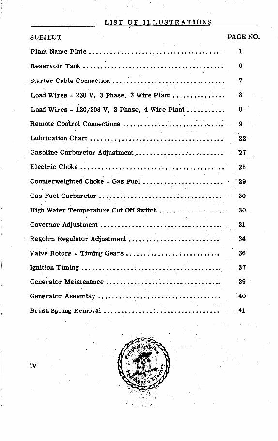
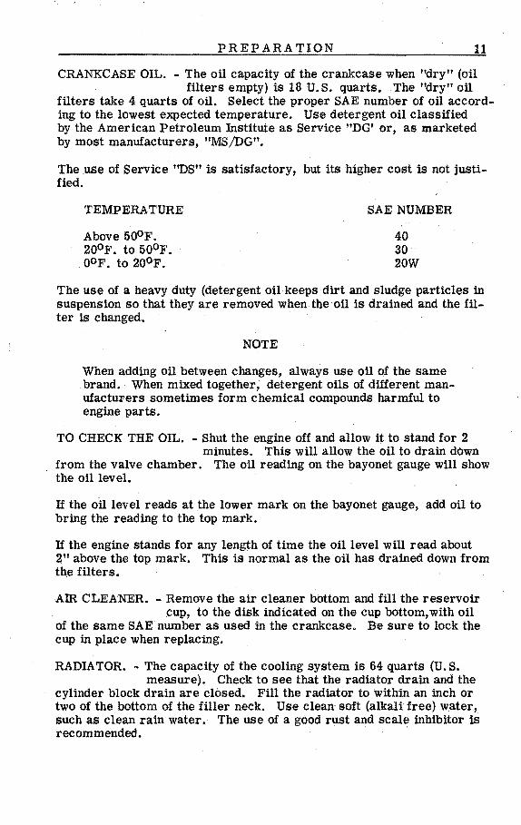
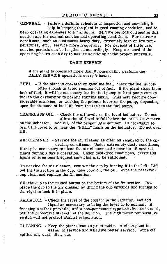
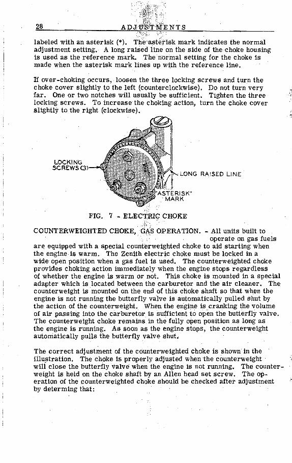
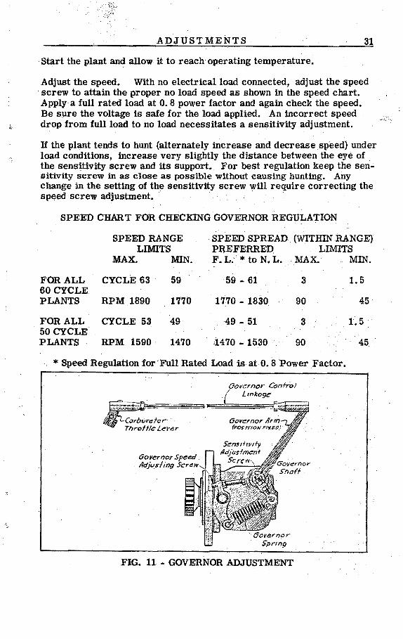
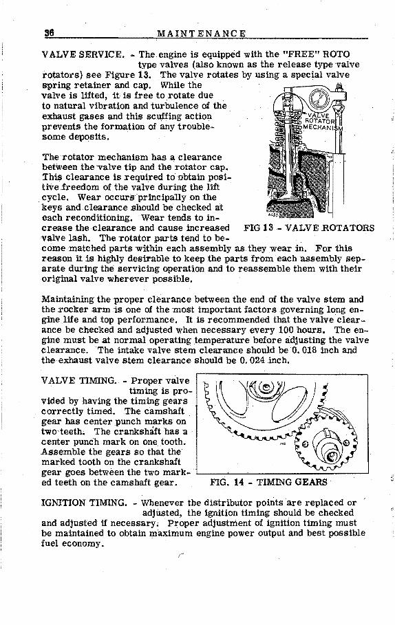
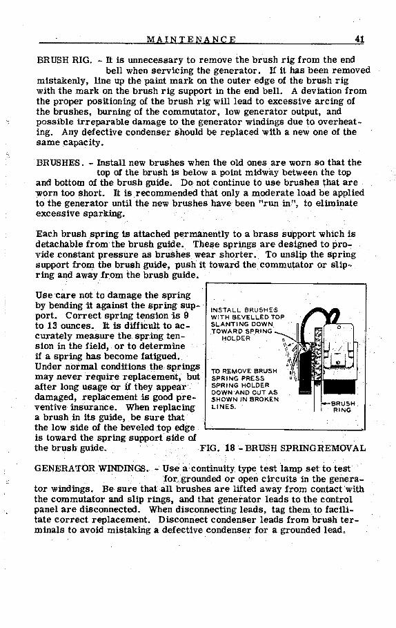
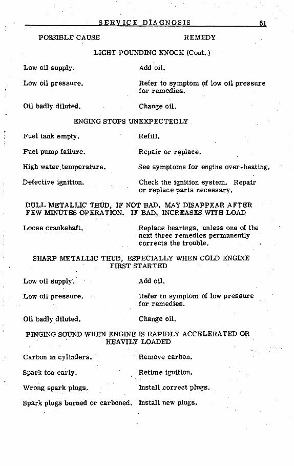

i
I ~