general laying procedures
DESCRIPTION
cable lay analysisTRANSCRIPT
GENERAL PROCEDURE FOR LAYING OF SUBMARINE CABLES (REV. 1 OCTOBER 2002) - PAGE 1
GENERAL PROCEDURE
FOR LAYING OF
SUBMARINE CABLES

INDEX
1 SCOPE Pag. 4
2 SUBMARINE CABLE Pag. 4
3 LAYING VESSEL Pag. 4
4 SERVICE MEANS Pag. 6
5 PERSONNEL Pag. 6
6 LAYING EQUIPMENT Pag. 6
6.1 MOTORIZED SPOOLS Pag. 6
6.2 MODULAR TURNTABLE TANKS Pag. 8
6.3 LINEAR MACHINE Pag. 9
6.4 TOPOGRAPHIC EQUIPMENT Pag. 9
6.5 DIVING EQUIPMENT Pag. 10
6.6 ACCESSORIES & MISCELLANEOUS Pag. 11
7 PRELIMINARY SURVEY Pag. 12
8 INSTALLATION Pag. 13
8.1 PRELIMINARY OPERATIONS Pag. 13
8.2 LAYING BETWEEN TWO PLATFORMS Pag. 14
8.3 LAYING BETWEEN LAND/PLATFORM TO LAND Pag. 17
GENERAL PROCEDURE FOR LAYING OF SUBMARINE CABLES (REV. 1 OCTOBER 2002) - PAGE 2

8.4 PRELIMINARY TEST DURING LAYING Pag. 19
8.5 POST BURYING Pag. 19
8.6 TERMINATIONS AND ACCESSORIES Pag. 19
8.7 SUBMARINE JOINTS & REPAIR WORKS Pag. 20
8.8 FINAL TEST Pag. 20
8.9 ”AS BUILT” DOCUMENTATION Pag. 20
INDEX
GENERAL PROCEDURE FOR LAYING OF SUBMARINE CABLES (REV. 1 OCTOBER 2002) - PAGE 3

LAYING OF SUBMARINE CABLES
1 SCOPE
Here follow general procedures adopted by P.C.S. Italiana for submarine cables laying be-tween platform and land, between two platforms or between island and land.
2 SUBMARINE CABLE
According to relevant dimensions (diameter, weight, length, etc.), the cable could be sentfrom the manufacturing Plant as per following options:
• Lengths shorter than 2.000 m: on regular drum ready to be set on the tensioning ma-chine.
• Lengths longer than 2.000 m: on special drum; once on board, the cable will be trans-ferred on suitable spool or tank.
• Lengths over 5.000 m in order to reach the requested length, special drums with maxi-mum cable length possible will be sent to the yard in order to carry out “Field FactoryJoints”, before loading on board of the laying vessel on the final requested length.
3 LAYING VESSEL
Laying vessel will be chosen according to cable and site characteristics and following crite-ria:
910
10
GENERAL PROCEDURE FOR LAYING OF SUBMARINE CABLES (REV. 1 OCTOBER 2002) - PAGE 4
6 - Linear Machine7 - Stinger8 - Laying stern barge
9 - Remote Control Room
10 - Video-TV localization
1 - Motorized spool2 - Hydraulic power units5 - Container

For long length cable, laying vessel will be exclusively a D.P. Vessel and laying equipmentinstalled on board will be composed by adequate turntable (one or more than one) andLinear Machine in accordance to the quantity of cable to be installed and “Laying plan”.
• Supply vessel or self-propelled barge or floating barge having preferably a dynamic positioningsystem GPS compatible or alternatively with joystick and bow thruster or two propellers.
• Suitable dimensions in order to guarantee the maximum manoeuvrability and safety.
• Low draught, when cable has to be laid between land and platform/island, in order to allowmooring close to land.
• Mooring system suitable for the site conditions, in order to maintain a safe position insafety conditions.
• Suitable space on on the deck to place the laying equipment.
GENERAL PROCEDURE FOR LAYING OF SUBMARINE CABLES (REV. 1 OCTOBER 2002) - PAGE 5

Standardmotorizedspool
4 SERVICE MEANS
For the auxiliary operations the following means shall be foreseen:
• Additional supply vessel D.P.or 4 points anchor winch system for diving assistance ondeep water (if necessary).
• Suitable motorboat and/or inflatable boat with outboard engine.
• Fast launch for personnel transport to land in case they can not stay overnight on boardof the main barge.
5 PERSONNEL
Laying and control operations, electrical connections, etc. will only be made by our special-ized personnel. External personnel could be employed only for crews, diving team and fornon specialist operations.
6 LAYING EQUIPMENT
The main equipment to be used for laying could be either motorized spool or modular cabletank as hereunder specified:
6.1. MOTORIZED SPOOLS
Two different motorized spools are available :
• Standard (for drums > 10 Tons.) (Dimensions: accepted for regular transportation)• Medium (for drums > 120 Tons.) (Max. Dimensions: Ø int. 2.00 m - Ø ext. 4.20 m
- Length 6.00 m)
Drums
For standard and medium motorized spool, the drum utilized for transportation is the sameused for laying.
GENERAL PROCEDURE FOR LAYING OF SUBMARINE CABLES (REV. 1 OCTOBER 2002) - PAGE 6

Motorization
In accordance with laying necessities,the motorization will be made by:
• different hydraulic power units (elec-tric or diesel) with relevant hydraulicpumps from 20 to 300 HP.
• Electric generators from 60 to 200kW
• Hydraulic engines from 1,200 kg/mto 12,000 kg/m
Accessories
• Laying automatism.• Length and stress meter.• Stinger• Roller way
Maximum concentrated load
All our motorized spools are dimen-sioned to allow a max. concentratedload on the deck (on laying vessel) of 5T/m²
“Medium” and “maxi” motorized spool
GENERAL PROCEDURE FOR LAYING OF SUBMARINE CABLES (REV. 1 OCTOBER 2002) - PAGE 7

6.2 MODULAR TURNTABLE TANKS
We have the following 4 different type of modular turntable tanks:
• Mini (max. capacity > 200 Tons) max. dimensions: Ø int. 2.50 m - Ø ext.6.00 m - Height 2.00 m
• Small (max. capacity > 400 Tons) max. dimensions: Ø int. 2.50 ÷ 4.00 m - Ø ext.9.80 m - Height 3.00 m
• Medium (max. capacity > 1,000 Tons) max. dimensions: Ø int. 2.50 ÷ 4.00 m - Ø ext.13.20 m - Height 3.00 m
• Maxi (max. capacity > 2,000 Tons) max. dimensions: Ø int. 2.50 ÷ 4.00 m - Ø ext.16.00 m - Height 3.00 m)
Motorization
In accordance with laying necessities, the motorization will be made by:
• Different hydraulic power units HP 300 - 600 - 800 - 1000 with relevant hydraulic pumps.• Electric generators from 60 kV till the requested power.• Hydraulic engines to be used in couple (2, 4, 6 or 8) according to performance prescriptions.
Accessories
• Automatism necessary for laying.• Length and stress meter.• Stinger.• Roller way.
Maximum concentrated load
Our turntable tanks are dimensioned for a max. concentrated load on the deck of 5 T/m² (for MaxiTank could be possible to reach in some case 10 T/m²).
GENERAL PROCEDURE FOR LAYING OF SUBMARINE CABLES (REV. 1 OCTOBER 2002) - PAGE 8

6.3 LINEAR MACHINE
Linear machine can be used both to haul cable for loading and recovery from the seabed andto act as hydraulic brake when laying cable onto the seabed to maintain the correct amountof residual tension.Actually are available No. 2 linear machines having following data:
- LM 8-5 tracked tension shoe with max pulling force of 8 Tons and max speed of 5 km/h -length of crawlers 3,20 meters.
- Modular LM 35-5 tracked tension shoe with max pulling force of 35 Tons and max speedof 5 km/h - Assembling of crawlers: n° 4 opposed crawlers with a length of 8 meters/each.This machine is installed on a special reclinable skid in oder to lay directly the cablewithout stinger.
The equipment is completed by a monitoring and manoeuvring panel (settings: automatic,manual and safety) which comprise: speed meter, cable pulling meter, counter meter andother laying parameters.
6.4 TOPOGRAPHIC EQUIPMENT
Following main instruments are normally used for preliminary survey and laying operations:
• GPS Tremble or equivalent• Computerized topographic station GEOTRONIC 422 LR• Echo sounding Atlas Krupp DESO 25 or equivalent with sub bottom possibility
Linear Machine LM 8-5
• Magnetometer FOSTER FOREX 4021• Side scan sonar (if necessary)• Boring machine for sea bottom samples• Underwater cameras (T.V. and photo)
GENERAL PROCEDURE FOR LAYING OF SUBMARINE CABLES (REV. 1 OCTOBER 2002) - PAGE 9

6.5 DIVING EQUIPMENT
For shallow water immersions (20 ÷ 40 mts.) during preliminary survey and laying will beused the following equipment:• Air bottles• High pressure compressor for bottles charging• Low pressure compressor (for narghilè)• Decompression chamber• Underwater cameras (T.V. and photo)
• Underwater communication system• Underwater tools (hydraulic hammer, underwater screwer, hydraulic grinder, underwater
core equipment, etc.)• Hydrodines and different floaters• Water lift and water jets equipment• Submersible high pressure pumps for “INCAVATRICE” water lift and water jets equipment
• ToolsIn case of required or necessary burying of the cable (for its total length) we have alsoavailable our burying machines “INCAVATRICE” (patent 1215709) type FS1 or FS2 able toreach two meters under the seabed.In case of diving assistance or R.O.V. (Remote Operated Vehicle) in deep water (over 40meters) we can rely on specialized and well equipped subcontractors with saturation sys-tems.They will be selected according to: job peculiarities, relevant experience.
• Seawater sampler• Thermometers• Current meters• Soil resistivity tester• VHF radio
GENERAL PROCEDURE FOR LAYING OF SUBMARINE CABLES (REV. 1 OCTOBER 2002) - PAGE 10
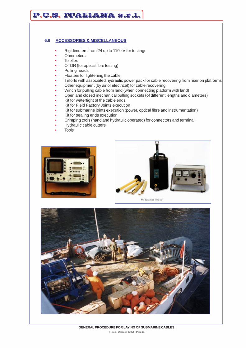
6.6 ACCESSORIES & MISCELLANEOUS
• Rigidimeters from 24 up to 110 kV for testings• Ohmmeters• Teleflex• OTDR (for optical fibre testing)• Pulling heads• Floaters for lightening the cable• Tirforts with associated hydraulic power pack for cable recovering from riser on platforms• Other equipment (by air or electrical) for cable recovering• Winch for pulling cable from land (when connecting platform with land)• Open and closed mechanical pulling sockets (of different lengths and diameters)• Kit for watertight of the cable ends• Kit for Field Factory Joints execution• Kit for submarine joints execution (power, optical fibre and instrumentation)• Kit for sealing ends execution• Crimping tools (hand and hydraulic operated) for connectors and terminal• Hydraulic cable cutters• Tools
GENERAL PROCEDURE FOR LAYING OF SUBMARINE CABLES (REV. 1 OCTOBER 2002) - PAGE 11

GENERAL PROCEDURE FOR LAYING OF SUBMARINE CABLES (REV. 1 OCTOBER 2002) - PAGE 12
7 PRELIMINARY SURVEY
In accordance with the Customer, immediately after the awarding of the contract, it will becarried out a preliminary survey in order to verify the effective validity of the proposed cableroute or to search for eventual alternative routes and to identify main engineering points.
It will be carried out the following activities:• Topographic investigation at landing areas and bench marks.• Bathimetric investigation along the cable route with concentration on the landing and in
eventual critical points.• Standard sub-bottom and/or soft sub-bottom analysis by means of further echo sounder
transducers.• Magnetometric investigation to find eventual services or presence of metallic pieces
with landing points relief.• Side scan sonar investigation (if necessary)• Execution of little borings or penetration testing on landing points in order to select the
better cable protection system.In case the protection will be required for the complete length of the cable, such evalu-ation will also be made in other points along the route.Obtained samples will be analysed in laboratory.
• Superficial sampling of the seabed soil.• Marine current investigation of the laying area.• Sampling of water sea and relevant analysis.• Underwater inspection in critical points and on landing points.• Platform investigation risers, risers to cabin cable route, winches anchoring points for
recovering of the cable from the riser and deviation points definition.• Data collection from Authorities to identify eventual existing or programmed services
interfering with the cable route.• Investigation about eventual obstacles or crossings (other cables, sealines, water pipes
etc.).• Soil resistivity on the interested land portion.• Collection of authorizations and prescriptions to be respected during job execution.• Study of the mooring plan of the naval equipment on site and eventual marker buoys to
be agreed with local authorities.• Specific arrangements to be taken to make the job.• Specific marking or signals (if required by local Authorities).• Collection of all possible meteorological data from local offices and whichever useful to
make job engineering and execution.• Verification of available lifting equipment in the area.• Verification of available stocking space in the area.• Selection of potential subcontractors for civil works.• Custom, harbour and agency fees on site.• Transportation of supply material and equipment and searching for personnel lodging.
Data processing, maps and sketches drawing and relevant rendering will be handled byour technical dept. at finishing of the laying project which consist of:
• Identification of the landing points and definition of the cable lengths.• Identification of the type of cable protection on the landing and on critical points.• Definition of installation and laying procedure.• Definition of the type and number of testing to be executed before, during and after
laying.• Definition of emergency procedures (abandon, adverse weather conditions etc.).• Identification of suitable equipment and vessel for the laying, definition of the deck charging
for the equipment.

• Cable burial procedure, type of “INCAVATRICE” equipment to be used and relevantaccessories to guarantee the defined burial depth.
• Definition of site Quality Control Plan (QCP).• Issuing of the definitive working schedule.• Definition of the final project, cable manufacturing plan and supply accessories.• Final verification and analysis.• Provisional jobs to execute.
8 INSTALLATION
8.1 PRELIMINARY OPERATIONS
As soon as site organisation (personnel and equipment) will be mobilized and operativeand in accordance to the working schedule and site QCP, it will be carried out followingpreliminary operations:
• On the deck of the laying vessel will be installed the laying equipment in accordancewith the cable length and water depth.Cable drum will be transferred on board and installed on the motorized spool or thecable will be transferred on the turntable tank according to the defined laying proce-dure medium and short length of cable.
• Installation of the adequate turntable (one or more than one) for long length of cable.• Installation of the adequate Linear Machine in accordance to the “laying plan”.• Defined route will be marked with special reference points and the definitive route will
be inserted into the GPS system• If necessary, critical points and crossings could also be indicated.
Anyway these will be as well inserted into the GPS system.• In case the laying will be made with a vessel having a DP system, GPS will be con-
nected to the system.
GENERAL PROCEDURE FOR LAYING OF SUBMARINE CABLES (REV. 1 OCTOBER 2002) - PAGE 13
SAMPLE OF AXONOMETRIC MAPWITH FINAL CABLE ROUTE(Lago Maggiore - Italy)

CentralinaTirfort
Riser
Rinvio
Cavo elettrico
• On the platform will be anchored the pulling winch to recover the cable from the riserand the necessary steel structures.
• In case of land/island connection, at the landing points will be positioned winchesand all necessary to recover the cable.
• In case necessary, it will also be installed the emergency mooring system or to beused by the auxiliary means
• All laying, submarine, topographic and floaters equipment will be tested and cali-brated. The same will apply to communication, control and testing equipment.
• Buoys field will be installed in connection to what already defined.• Verification of the “messenger line” inserted into the risers on platform.• Personnel and equipment will be settled for laying trial which will continue until all
manoeuvres and co-ordination between technical, maritime and underwater techni-cians is reached.
8.2 LAYING BETWEEN TWO PLATFORMS
In good meteorological condition and with good weather forecast, the laying barge willmoor near the starting platform.The power cable end (with pulling socket and swivel already placed) will be connected tothe messenger line already threaded into the riser.From the platform, by means of the installed winch, it will be carried out the recovery ofthe messenger line while on the laying vessel is left the quantity of cable required by thewinch operator.Pulling and recovering of power cable from the riser is made by the winch and control isobtained by the dynamometer placed at the deviation point or on the hydraulic powerunit.If necessary, divers and/or R.O.V. can control the introduction of the cable inside theriser or any other eventual critical phase of the work.
GENERAL PROCEDURE FOR LAYING OF SUBMARINE CABLES (REV. 1 OCTOBER 2002) - PAGE 14

As soon as the necessary quantity of power cable has been recovered on platform a specialclamp will be installed to stop the cable on the top of the riser.Only at this point the launching operation starts.During this phase, the laying equipment shall be regulated on “AUTOMATIC POSITION” inorder to distribute in the proper way the defined tension on the cable and to avoid, conse-quently, the possibility of any damage.Anyway the equipment will work under surveillance and manual intervention could be made atany time.
GENERAL PROCEDURE FOR LAYING OF SUBMARINE CABLES (REV. 1 OCTOBER 2002) - PAGE 15

The laying vessel, keeping thestated velocity, will movealongside the fixed course,while paying out the cablewhich starts from the motor-ized spool (or the turntabletank) and passes through thelinear machine.Near the arriving platform thelaying vessel will pay out theremaining portion of cable, af-ter connection of adequatelightening floaters in order toavoid any possibility of bury-ing the cable during this phaseof work.
GENERAL PROCEDURE FOR LAYING OF SUBMARINE CABLES (REV. 1 OCTOBER 2002) - PAGE 16
Spi
aggi
a
Spi
aggi
a
Profilo fondo marino
Profilo fondo marino
Nave posacavi
Nave posacavi
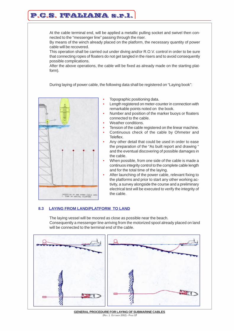
At the cable terminal end, will be applied a metallic pulling socket and swivel then con-nected to the “messenger line” passing through the riser.By means of the winch already placed on the platform, the necessary quantity of powercable will be recovered.This operation shall be carried out under diving and/or R.O.V. control in order to be surethat connecting ropes of floaters do not get tangled in the risers and to avoid consequentlypossible complications.After the above operations, the cable will be fixed as already made on the starting plat-form).
During laying of power cable, the following data shall be registered on “Laying book”:
• Topographic positioning data.• Length registered on meter-counter in connection with
remarkable points noted on the book.• Number and position of the marker buoys or floaters
connected to the cable.• Weather conditions.• Tension of the cable registered on the linear machine.• Continuous check of the cable by Ohmeter and
Teleflex.• Any other detail that could be used in order to ease
the preparation of the “As built report and drawing “and the eventual discovering of possible damages inthe cable.
• When possible, from one side of the cable is made acontinuos integrity control to the complete cable lengthand for the total time of the laying.
• After launching of the power cable, relevant fixing tothe platforms and prior to start any other working ac-tivity, a survey alongside the course and a preliminaryelectrical test will be executed to verify the integrity ofthe cable.
8.3 LAYING FROM LAND/PLATFORM TO LAND
The laying vessel will be moored as close as possible near the beach.Consequently a messenger line arriving from the motorized spool already placed on landwill be connected to the terminal end of the cable.
GENERAL PROCEDURE FOR LAYING OF SUBMARINE CABLES (REV. 1 OCTOBER 2002) - PAGE 17

Profilo del fondo marino
± 0.00 Bat
tigia
Spi
aggi
a
Nave Posacavi
Cav
o co
n ga
llegg
iant
i
Spi
aggi
a
Nav
e P
osac
avi
Mot
obar
ca
Nave Posacavi
Cav
o co
n
Spi
aggi
a
Mot
obar
caCavo varato
Cavo varato
galleggianti
At the end of this opera-tion will start the recov-ery of the cable.As cable is paid outfrom the vessel, suitablefloaters (distance be-tween them is defined inthe final project) will beconnected in order toavoid the cable sinkingin the sea-bottom.
After recovery of the re-quired portion of powercable, floaters shall bedisconnected and a sub-marine survey will be car-ried out to understand ifthe cable has landed inposition.
After fixing of the cableon land and positive re-sult of the survey, thelaying phase will startand all following activi-ties are made as per theconnection between plat-forms.
At the end of this opera-tion will start the recov-ery of the cable.
GENERAL PROCEDURE FOR LAYING OF SUBMARINE CABLES (REV. 1 OCTOBER 2002) - PAGE 18

8.6 TERMINATIONS AND ACCESSORIES
In addition to the above, we are able to supply and install thefollowing accessories:
Platforms connection
• cable fixing clamps to risers (both single and multiples)• polyfunctional joint boxes• indoor and outdoor terminations• submarine repair joints• pulling heads• bending restrictors• special liquid to be inserted into the riser to protect the
cable in “splash zones”• inox steel and galvanized iron covers for cable
protection• special manufactures for services crossings
Connection on landIn addition to the above, we foresee the specific ac-cessories:
• submarine land/sea joints• anchoring cable system• cable earthing with eventual dischargers closing
to the joint bay
8.4 PRELIMINARY TEST FORESEEN DURING THE INSTALLATION OF A SUBMARINECABLE
In case of doubt for damages occurred during cable transportation, the power cable could betested before starting installation operations.Anyway a previous test is made at the end of laying activities in order to demobilize thelaying vessel.In case the project foresees a “post burying” of the cable, a new test will be carried out afterthis activity in order to guarantee that no damages have occurred and to demobilize person-nel and equipment.
8.5 POST BURYING
In addition to the normal protection foreseen at the landing points and if foreseen by thedesign, by means of our burial machine “INCAVATRICE”, we are also able to carry out theburial of the cable for its complete length up to the maximum penetration depth of twometers under the seabed.For further details see the enclosed documentation.
GENERAL PROCEDURE FOR LAYING OF SUBMARINE CABLES (REV. 1 OCTOBER 2002) - PAGE 19

8.7 SUBMARINE JOINTS & REPAIR WORKS
For safety reasons, during laying activities, it is necessary to be prepared to a possiblecable damage.In order to overcome such a problem, the organization has to be in condition to findwhere the damage has occurred and proceed with the repair as soon as possible.For this reason is usually foreseen in our personnel one technician who is specialized injoint execution and could anyway work on termination and joint boxes connection.For the same reason we always prefer to include in our offer a set of submarine sparejoints which will be kept for future needs in the normal case that during installationactivities no damages will arise to the cable.Jointing procedures are anyway listed in the jointing instructions contained in the jointkit.
8.8 FINAL TEST
As soon as all site jobs have been executed, a final test of the total “system” will bemade according to the ruling standards, the project design accepted/required by theCustomer.
8.9 “AS BUILT” DOCUMENTATION
At the end of the installation works, all information regarding the cable system and thelaying operations daily registered in the “laying book”, together with all the documentationrelated to cable, accessories etc. and the available photographic or video documentationis consigned to the Customer, within two months from the final test date, in the “as built”documentation.
GENERAL PROCEDURE FOR LAYING OF SUBMARINE CABLES (REV. 1 OCTOBER 2002) - PAGE 20