general licensing classgeneral licensing class g2...
TRANSCRIPT

4/29/2012
1
General Licensing ClassGeneral Licensing Class
Subelement G9
Antennas and FeedlinesAntennas and Feedlines
4 Exam Questions, 4 Groups
General Class Element 3 Course P t tiPresentation
ELEMENT 3 SUB ELEMENTSELEMENT 3 SUB‐ELEMENTS
G1 – Commission’s RulesG2 – Operating ProceduresG2 Operating ProceduresG3 – Radio Wave PropagationG4 – Amateur Radio PracticesG5 – Electrical PrinciplesG6 – Circuit ComponentsG7 – Practical CircuitsG8 – Signals and EmissionsG9 A tG9 – AntennasG0 – Electrical and RF Safety
2
AntennasThe distance between the centers of the conductors and the radius of the conductors determine the characteristic impedance of a parallel conductor antenna feed lineimpedance of a parallel conductor antenna feed line. (G9A01)
d h h l h d f300 Ohm Twin Lead Air Dielectric Coaxial Cable Parallel two-wire line
50 and 75 ohms are the typical characteristic impedances of coaxial cables used for antenna feed lines at amateur stations. (G9A02)
Ant Antennas nnas
300 ohms is the characteristic impedance of flat300 ohms is the characteristic impedance of flat ribbon TV type twinlead. (G9A03)
A difference between feed line impedance andA difference between feed‐line impedance and antenna feed‐point impedance is the reason for the occurrence of reflected power at the point where a f d lifeed line connects to an antenna. (G9A04)
The attenuation of coaxial cable increases as the frequency of the signal it is carrying increases (G9A05)frequency of the signal it is carrying increases. (G9A05)
RF feed line losses usually expressed in dB per 100 ftft. (G9A06)
4
Ant Antennas nas Ant Antennas as
To prevent standing waves on an antenna feed line, the antenna feed‐point impedance must be matched to the p pcharacteristic impedance of the feed line. (G9A07)
If the SWR on an antenna feed line is 5 to 1, and a matching network at the transmitter end of the feed line is adjusted tonetwork at the transmitter end of the feed line is adjusted to 1 to 1 SWR, the resulting SWR on the feed line is still 5 to 1. (G9A08)
• The antenna tuner allows the transmitter to see a matched impedanceThe antenna tuner allows the transmitter to see a matched impedance • This delivers full power. • It does not change the antenna or feedline impedance on its output.
Antenna tuner with built in d l dldual needle SWR meter

4/29/2012
2
Ant Antennas nnas
A 4:1 standing wave ratio will result from the connection of a 50‐ohm f d li t ti l d h i 200 h i dfeed line to a non‐reactive load having a 200‐ohm impedance. (G9A09)
SWR = Z1 / Z2
200/ 50200/ 50
4:1 VSWR
A standing wave ratio of 5:1 will result from the connection of a 50‐ohm feed line to a non‐reactive load having a 10‐ohm impedance. (G9A10)
SWR = Z1 / Z2
50/ 1050/ 10
5:1 VSWR
Ant Antennas ennas
A standing wave ratio of 1:1 will result from the connection of a 50‐ohm feed line to a non‐reactive load having a 50‐
h i dohm impedance. (G9A11)
SWR = Z1 / Z2 50 / 50 1 : 1 VSWR
Anten Antennas nas
If you feed a vertical antenna that has a 25‐ohm feed‐point impedance with 50 ohm coaxial cable the SWR will be 2:1impedance with 50‐ohm coaxial cable, the SWR will be 2:1. (G9A12)
If you feed an antenna that has a 300‐ohm feed‐point i d ith 50 h i l bl th SWR ill b 6 1
50 / 25 2:1 VSWRSWR = Z1 / Z2
impedance with 50‐ohm coaxial cable, the SWR will be 6:1. (G9A13)
SWR = Z1 / Z2 300/ 50 6:1 VSWR
One disadvantage of a directly fed random‐wire antenna is that you may experience RF burns when touching metal objects in your station. (G9B01)
• As the name implies, random‐wire antennas are a random‐length.
• To match the antenna to the transmitter, you’ll need an antenna tuner
• Because of this, there may be high RF levels in the shack when you are transmitting.
Anten Antennas nasAnten Antennas nas
An advantage of downward sloping radials on a quarter wave ground‐plane antenna is that they bring the feed‐point impedance closer to 50 ohms. (G9B02)
The natural feed point of a quarter‐wave vertical is 35 ohmsThe natural feed point of a quarter‐wave vertical is 35 ohms, but the feed‐point impedance of a ground‐plane antenna increases when its radials are changed from horizontal to downward‐sloping. (G9B03)downward sloping. (G9B03)
– Bending the radials changes the impedance up towards 50 ohms.
Notice ground plane elements are angled downwards.
Ant Antennas ennasAnt Antennas ennas
The low angle azimuthal radiation pattern of an ideal half‐wavelength dipole antenna installed 1/2 wavelength high andwavelength dipole antenna installed 1/2 wavelength high and parallel to the Earth is a figure‐eight at right angles to the antenna. (G9B04)
If the antenna is less than 1/2 wavelength high, the azimuthalpattern is almost omnidirectional and maximum straight up. (G9B05)(G9B05)
Omni‐directional patternPatterns change as height above ground is varied
Ant Antennas ennasAnt Antennas ennas
Calculate ½ wavelength in feet by dividing 468 by the frequency in MHz.
The radial wires of a ground‐mounted vertical antenna system should be
g y t e eq e cy468/28.516.4 Feet
A ¼ wave antenna would be ½ the length of a ½ wave antennaantenna system should be
placed on the surface or buried a few inches below the ground
the length of a ½ wave antenna16.4/28.2 Feet
the ground. (G9B06)
Surface t dGround wire kit. mounted
ground wires.

4/29/2012
3
Ant Antennas ennasAnt Antennas ennas
As the antenna is lowered from 1/4 wave above ground, the feed point impedance of a 1/2 wave dipole antenna steadilyfeed‐point impedance of a 1/2 wave dipole antenna steadily decreases. (G9B07)
– Antenna height affects the feed point impedance.
The feed‐point impedance of a 1/2 wave dipole steadily increases as the feed‐point location is moved from the center toward the ends (G9B08)toward the ends. (G9B08)
Ant Antennas ennasAnt Antennas ennas
An advantage of a horizontally polarized as compared to vertically polarized HF antenna is lower ground reflection losses. (G9B09)
– Propagation via multi‐hop refraction:
RF energy is lost each time the radio wave is reflected from the Earth's surface.
– The amount of energy lost depends on:
Frequency of the wave
Angle of incidence
Ground irregularities
Electrical conductivity of the point of reflection.
Ant Antennas ennasAnt Antennas ennas
32 feet is the approximate length for a 1/2 wave dipolelength for a 1/2‐wave dipole antenna cut for 14.250 MHz. (G9B10)
• Calculate ½ wavelength in feet by dividing 468 by• Calculate ½ wavelength in feet by dividing 468 by the frequency in MHz.
• 468 / 14.250 • 32.8 Feet
The approximate length for a 1/2‐wave dipole antenna cut for 3 550 MHz is 131 feetfor 3.550 MHz is 131 feet. (G9B11)
• Calculate ½ wavelength in feet by dividing 468 by the frequency in MHz.
• 468 / 3.550 or • 131.8 Feet131.8 Feet
Half-wave Dipole with 450 ohm feedline (not coax).
Ant Antennas ennasAnt Antennas ennas
Th i l h f 1/4 i lThe approximate length for a 1/4‐wave vertical antenna cut for 28.5 MHz is 8 feet. (G9B12)
Calculate ½ wavelength in feet byCalculate ½ wavelength in feet by dividing 468 by the frequency in MHz.
468/28.516.4 Feet
A ¼ wave antenna would be ½ the length of a ½ wave antenna
16 4/216.4/28.2 Feet
16
Ant Antennas ennasAnt Antennas ennas
Larger diameter elements increase the b d id h f ibandwidth of a Yagi antenna. (G9C01)
The approximate length of the driven pp gelement of a Yagi antenna is 1/2 wavelength. (G9C02)
In a three‐element, single‐band Yagi antenna, the director is normally the shortest parasitic element. (G9C03)shortest parasitic element. (G9C03)
The reflector is normally the longest parasitic element of a three elementparasitic element of a three‐element, single‐band Yagi antenna. (G9C04)
Ant Antennas ennasAnt Antennas ennas
The gain increases when youThe gain increases when you increase boom length and add directors to a Yagi antenna. (G9C05)
A Yagi antenna is often used for radio gcommunications on the 20 meter band because it helps reduce interference from other stations to the side or behind the antenna. (G9C06)

4/29/2012
4
Ant Antennas ennasAnt Antennas ennas
The "front‐to‐back ratio" of aThe front to back ratio of a Yagi antenna is the power radiated in the major radiation lobe compared to the power p pradiated in exactly the opposite direction. (G9C07)
The “major lobe” or "main lobe"The major lobe or main lobe of a directive antenna is the direction of maximum radiated field strength from the antennafield strength from the antenna. (G9C08)
Ant Antennas ennasAnt Antennas ennas
The approximate maximum theoretical forward gain of a three element single band Yagi antenna is 9 7 dBithree element, single‐band Yagi antenna is 9.7 dBi. (G9C09)
– dBi refers to a reference level of dB Isotropic
– which is the signal strength from an ideal point source of energy
– that radiates equally in all directions in a sphere surrounding the point RF source.q y p g p
– Isotropic radiators are used as reference radiators – An isotropic radiator is a theoretical point source of electromagnetic or sound waves.
Ant Antennas ennasAnt Antennas ennas
In a Yagi antenna design, the following variables that could be adjusted to optimize forward gain, front‐to‐back ratio, or SWR bandwidth (G9C10)
– The physical length of the boom
– The number of elements on the boom
– The spacing of each element along the boom
All of these choices are correct
Ant Antennas ennasAnt Antennas ennas
The purpose of a gamma match used with Yagi antennas is to t h th l ti l l f d i t i d t 50 hmatch the relatively low feed‐point impedance to 50 ohms. (G9C11)
An advantage of using a gamma match for impedance matching of a Y i 50 h f d li i h i d iYagi antenna to 50‐ohm coax feed line is that it does not require that the elements be insulated from the boom. (G9C12)
Ant Antennas ennasAnt Antennas ennas
The elements of a quad antenna are square loops. Each side of a quad antenna driven element is approximatelyside of a quad antenna driven element is approximately 1/4 wavelength. (G9C13)
Driven Element forDriven Element for each side (in feet) =
1005/ 4
f (MHz) / 4
Horizontal polarization feed pointHorizontal polarization feed-point
Ant Antennas ennasAnt Antennas ennas
The forward gain of a two‐element quad antenna is about the same as the forward gain of a three‐element Yagi antenna. (G9C14)the forward gain of a three element Yagi antenna. (G9C14)
Each side of a quad antenna reflector element is slightly more than 1/4 wavelengthwavelength. (G9C15)

4/29/2012
5
Ant Antennas ennasAnt Antennas ennas
The gain of a two‐element delta‐loop beam is about the same as theThe gain of a two element delta loop beam is about the same as the gain of a two‐element quad antenna. (G9C16)
Driven Element forDriven Element for each side (in feet) =
10053/f (MHz)3/
Each leg of a symmetrical delta‐loop antenna is approximately 1/3 l h
g y p pp ywavelength. (G9C17)
Ant Antennas ennasAnt Antennas ennas
The polarization of the radiated signal changes from horizontal to vertical when the feed point of a quad antenna is changed from thevertical when the feed point of a quad antenna is changed from the center of the either horizontal wire to the center of either vertical wire. (G9C18)
The reflector element must be approximately 5% longer than the driven element for a two‐element quad antenna when the antenna is
b i f h lmeant to operate as a beam antenna, assuming one of the elements is used as a reflector. (G9C19)
Yagi antennas spaced vertically 1/2 wavelength apart typically is approximately 3 dB higher than the gain of a single 3‐element Yagiapproximately 3 dB higher than the gain of a single 3‐element Yagi. (G9C20)
Ant Antennas ennas
The term "NVIS" means Near Vertical Incidence Sky wave whenVertical Incidence Sky wave when related to antennas. (G9D01)
An advantage of an NVIS antennaAn advantage of an NVIS antenna is high vertical angle radiation for working stations within a radius of a few hundred kilometers. (G9D02)
Angle of radiation determines the area
of coverage
Ant Antennas ennas
An NVIS antenna typically installed between 1/10 and 1/4 wavelength above ground. (G9D03)
The primary purpose of antenna traps is to permit multiband operation. (G9D04)
Ant Antennas ennas
The advantage of vertical stacking of horizontally polarized Yagi antennas is that it narrows the mainpolarized Yagi antennas is that it narrows the main lobe in elevation. (G9D05)
Vertical Stacking of Horizontally polarized.
Horizontal Stacking of Vertically polarized.y p y p
Ant Antennas ennas
The gain of a log periodic antenna is less than that of a Yagi, but an advantage of a log periodic antenna is wide b d id hbandwidth. (G9D06)
For a log periodic antenna, the length and spacing of the elements increases logarithmically from one end of theelements increases logarithmically from one end of the boom to the other. (G9D07)
290 – 2000 MHz 0.15 – 300 MHzEW8DQ, and his rotatable HF log-periodic beam antenna in Belarus290 2000 MHz 0.15 300 MHzperiodic beam antenna in Belarus

4/29/2012
6
Ant Antennas ennas
A Beverage antenna is not used for transmitting because it has ghigh losses compared to other types of antennas. (G9D08)
An application for a BeverageAn application for a Beverage antenna is as a directional receiving for low HF bands. (G9D09)
A Beverage antenna is a veryA Beverage antenna is a very long and low directional receiving antenna. (G9D10)
Ant Antennas ennasAnt Antennas ennas
A disadvantage of multiband antennas is thatA disadvantage of multiband antennas is that they have poor harmonic rejection. (G9D11)
Hex Wire Beam multi bandFive band beam 20-10m
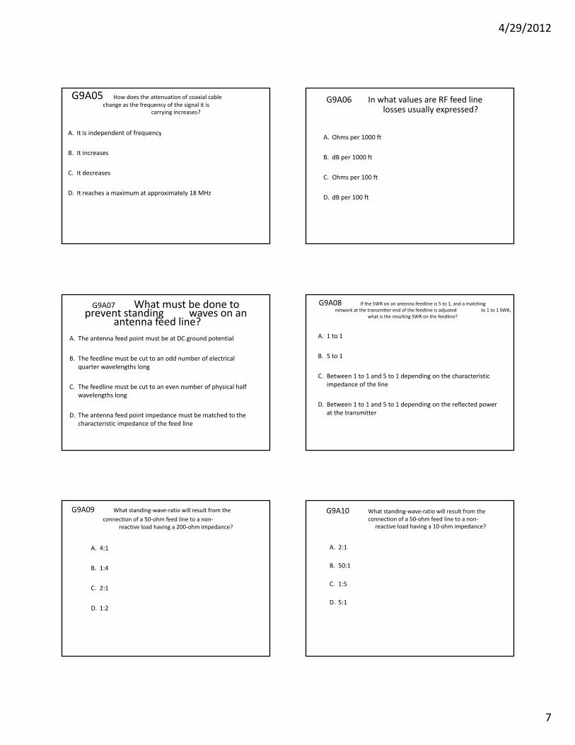
G9A01 Which of the following factors determine the characteristic impedance of a parallel
conductor antenna feed line?
A. The distance between the centers of the conductors and the radius of the conductors
B. The distance between the centers of the conductors and the length of the line
C. The radius of the conductors and the frequency of the signal
D. The frequency of the signal and the length of the line
G9A02 What are the typical characteristic impedances of coaxial cables used for antenna feed lines at
amateur stations?
A 25 d 30 hA. 25 and 30 ohms
B 50 and 75 ohmsB. 50 and 75 ohms
C. 80 and 100 ohms
D. 500 and 750 ohms
G9A03 What is the characteristic impedance of flat ribbon TVimpedance of flat ribbon TV
type twinlead? A 50 ohmsA. 50 ohms
B. 75 ohms
C. 100 ohms
D. 300 ohms
G9A04 What is the reason for the occurrence of reflected power at the point where a feedline
connects to an antenna?
A. Operating an antenna at its resonant frequency p g q y
B. Using more transmitter power than the antenna can handle
C. A difference between feed line impedance and antenna feed point impedancepoint impedance
D. Feeding the antenna with unbalanced feedlineD. Feeding the antenna with unbalanced feedline
4/29/2012
7
G9A05 How does the attenuation of coaxial cable change as the frequency of the signal it is
i i ?carrying increases?
A It is independent of frequencyA. It is independent of frequency
B. It increasesB. It increases
C. It decreases
D. It reaches a maximum at approximately 18 MHz
G9A06 In what values are RF feed line losses usually expressed?losses usually expressed?
A. Ohms per 1000 ft
d fB. dB per 1000 ft
C Ohms per 100 ftC. Ohms per 100 ft
D. dB per 100 ft p
G9A07 What must be done to prevent standing waves on anprevent standing waves on an
antenna feed line? A The antenna feed point must be at DC ground potentialA. The antenna feed point must be at DC ground potential
B. The feedline must be cut to an odd number of electrical quarter wavelengths long
C. The feedline must be cut to an even number of physical half wavelengths long
D. The antenna feed point impedance must be matched to the characteristic impedance of the feed line
G9A08 If the SWR on an antenna feedline is 5 to 1, and a matching network at the transmitter end of the feedline is adjusted to 1 to 1 SWR,
what is the resulting SWR on the feedline?what is the resulting SWR on the feedline?
A. 1 to 1
B. 5 to 1
C. Between 1 to 1 and 5 to 1 depending on the characteristic impedance of the lineimpedance of the line
D. Between 1 to 1 and 5 to 1 depending on the reflected powerD. Between 1 to 1 and 5 to 1 depending on the reflected power at the transmitter
G9A09 What standing‐wave‐ratio will result from the connection of a 50‐ohm feed line to a non‐
reactive load having a 200‐ohm impedance?
A. 4:1
B 1:4B. 1:4
C. 2:1C. 2:1
D. 1:2
G9A10 What standing‐wave‐ratio will result from the connection of a 50‐ohm feed line to a non‐
reactive load having a 10‐ohm impedance?
A 2 1A. 2:1
B. 50:1B. 50:1
C. 1:5
D. 5:1

4/29/2012
8
G9A11 What standing‐wave‐ratio will result from the connection of a 50‐ohm feed line to a non‐
reactive load having a 50‐ohm impedance?
A 2:1A. 2:1
B. 1:1B. 1:1
C. 50:50
D. 0:0
G9A12 What would be the SWR if you feed a vertical antenna that has a 25‐ohm feed‐point
impedance with 50‐ohm coaxial cable?
A 2:1A. 2:1
B. 2.5:1
C. 1.25:1
D. You cannot determine SWR from impedance values
G9A13 What would be the SWR if you feed a folded dipole antenna that has a 300‐ohm feed‐
point impedance with 50‐ohm coaxial cable?
A. 1.5:1
B. 3:1
C. 6:1
D. You cannot determine SWR from impedance values
G9B01 What is one disadvantage of a
directly fed random‐wire antenna?
A. It must be longer than 1 wavelengthg g
B. You may experience RF burns when touching metal objects in your station
C It produces only vertically polarized radiationC. It produces only vertically polarized radiation
D. It is not effective on the higher HF bandsD. It is not effective on the higher HF bands
G9B02 What is an advantage of downward sloping radials on a quarter wave ground‐plane antenna?
A They lower the radiation angleA. They lower the radiation angle
B. They bring the feed‐point impedance closer to 300 ohms
C. They increase the radiation angle
D. They bring the feed‐point impedance closer to 50 ohms
G9B03 What happens to the feed‐point impedance of a ground‐plane antenna when its radials are changed
f h i l d d l i ?from horizontal to downward‐sloping?
A It decreasesA. It decreases
B. It increases
C. It stays the same
D. It reaches a maximum at an angle of 45 degrees

4/29/2012
9
G9B04 What is the low angle azimuthal radiation pattern
of an ideal half‐wavelength dipole antenna installed 1/2 wavelength high and parallel to the Earth?
A. It is a figure‐eight at right angles to the antennag g g g
B. It is a figure‐eight off both ends of the antenna
C. It is a circle (equal radiation in all directions)
D. It has a pair of lobes on one side of the antenna and a single lobe on the other sidelobe on the other side
G9B05 How does antenna height affect the horizontal (azimuthal) radiation pattern of a horizontal
di l HF t ?dipole HF antenna?
A If the antenna is too high the pattern becomes unpredictableA. If the antenna is too high, the pattern becomes unpredictable
B. Antenna height has no effect on the patterng p
C. If the antenna is less than 1/2 wavelength high, the azimuthal pattern is almost omnidirectional
D If the antenna is less than 1/2 wavelength high radiation off theD. If the antenna is less than 1/2 wavelength high, radiation off the ends of the wire is eliminated
G9B06 Where should the radial wires of a ground‐mounted vertical antenna s stem be placed?antenna system be placed?
A As high as possible above the groundA. As high as possible above the ground
B. Parallel to the antenna element
C. On the surface or buried a few inches below the ground
D. At the top of the antenna
G9B07 How does the feed‐point impedance of a 1/2 wave dipole antenna change as the antenna is lowered
from 1/4 wave above ground?
A It steadily increasesA. It steadily increases
B. It steadily decreasesy
C. It peaks at about 1/8 wavelength above ground
D. It is unaffected by the height above ground
G9B08 How does the feed‐point impedance of a 1/2 wave dipole change as the feed‐point location is moved
from the center toward the ends?
A It steadily increasesA. It steadily increases
B. It steadily decreasey
C. It peaks at about 1/8 wavelength from the end
D. It is unaffected by the location of the feed‐point
G9B09 Which of the following is an advantage of a horizontally polarized as compared to
vertically polarized HF antenna?
A Lower ground reflection lossesA. Lower ground reflection losses
B. Lower feed‐point impedance
C. Shorter Radials
D. Lower radiation resistance

4/29/2012
10
G9B10 What is the approximate length for a 1/2‐wave dipole antenna cut for 14 250 MHz?dipole antenna cut for 14.250 MHz?
A 8 f tA. 8 feet
B 16 feetB. 16 feet
C. 24 feet
D. 32 feet
G9B11 What is the approximate length for a 1/2‐wave dipole antenna cut for 3.550 MHz?
A. 42 feet
B. 84 feet
C. 131 feet
D. 263 feet
G9B12 What is the approximate length for a / i l f 28 ?1/4‐wave vertical antenna cut for 28.5 MHz?
A 8 feetA. 8 feet
B. 11 feetB. 11 feet
C. 16 feet
D. 21 feet
G9C01 Which of the following would increase the bandwidth of aincrease the bandwidth of a
Yagi antenna? A Larger diameter elementsA. Larger diameter elements
B. Closer element spacing p g
C. Loading coils in series with the elements
D. Tapered‐diameter elements
G9C02 What is the approximate length f h d i l f Y i ?of the driven element of a Yagi antenna?
A 1/4 wavelengthA. 1/4 wavelength
B. 1/2 wavelengthB. 1/2 wavelength
C. 3/4 wavelength
D. 1 wavelength
G9C03 Which statement about a three‐element single‐band Yagithree element single band Yagi
antenna is true? A The reflector is normally the shortest parasitic elementA. The reflector is normally the shortest parasitic element
B. The director is normally the shortest parasitic element y p
C. The driven element is the longest parasitic element
D. Low feed‐point impedance increases bandwidth

4/29/2012
11
G9C04 Which statement about a three‐element single‐band Yagithree element, single band Yagi
antenna is true? A The reflector is normally the longest parasitic elementA. The reflector is normally the longest parasitic element
B. The director is normally the longest parasitic element
C. The reflector is normally the shortest parasitic element
D. All of the elements must be the same length
G9C05 How does increasing boom length d ddi di ff Y i ?and adding directors affect a Yagi antenna?
A Gain increasesA. Gain increases
B. Beamwidth increases
C. Weight decreases
D. Wind load decreases
G9C06 Which of the following is a reason why a Yagi antenna is often used for radio communications on the 20
meter band?
A It provides excellent omnidirectional coverage in the horizontalA. It provides excellent omnidirectional coverage in the horizontal plane
B. It is smaller, less expensive and easier to erect than a dipole or vertical antenna
C. It helps reduce interference from other stations to the side or behind the antenna
D. It provides the highest possible angle of radiation for the HF bands
G9C07 What does "front‐to‐back ratio" mean in reference to a Yagi antenna?
A The number of directors versus the number of reflectorsA. The number of directors versus the number of reflectors
B. The relative position of the driven element with respect to the p preflectors and directors
C. The power radiated in the major radiation lobe compared to the power radiated in exactly the opposite direction
D. The ratio of forward gain to dipole gain
G9C08 What is meant by the "main lobe" f di ti t ?of a directive antenna?
A The magnitude of the maximum vertical angle of radiationA. The magnitude of the maximum vertical angle of radiation
B. The point of maximum current in a radiating antenna elementp g
C. The maximum voltage standing wave point on a radiating element
D The direction of maximum radiated field strength from theD. The direction of maximum radiated field strength from the antenna
G9C09 What is the approximate maximum theoretical for ard gain of a 3 elementforward gain of a 3 element
single‐band Yagi antenna?A 9 7 dBiA. 9.7 dBi
B. 9.7 dBd
C. 5.4 times the gain of a dipole
D. All of these choices are correct

4/29/2012
12
G9C10 Which of the following is a Yagi antenna design variable that could be adjusted to optimize forward gain,
f t t b k ti SWR b d idth?front‐to‐back ratio, or SWR bandwidth?
A The physical length of the boomA. The physical length of the boom
B. The number of elements on the boom
C. The spacing of each element along the boom
D. All of these choices are correct
G9C11 What is the purpose of a gamma match used with Yagi antennas?
A. To match the relatively low feed‐point impedance to 50 ohmsy p p
B. To match the relatively high feed‐point impedance to 50 ohms
C To increase the front to back ratioC. To increase the front to back ratio
D. To increase the main lobe gainD. To increase the main lobe gain
G9C12 Which of the following is an advantage of using a gamma match for impedance matching of a Yagi
antenna to 50‐ohm coax feed line?antenna to 50‐ohm coax feed line?
A It does not require that the elements be insulated from theA. It does not require that the elements be insulated from the boom.
B. It does not require any inductors or capacitors.
i f l f hi l ib dC. It is useful for matching multiband antennas.
D All of these choices are correctD. All of these choices are correct.
G9C13 Approximately how long is each side of a quad antenna drivenside of a quad antenna driven
element? A ¼ wavelengthA. ¼ wavelength.
B. ½ wavelength.g
C. ¾ wavelength.
D. 1 wavelength.
G9C14 How does the forward gain of a two‐element quad antenna compare to the forward
f h l ?gain of a three‐element Yagi antenna?
A About 2/3 as muchA. About 2/3 as much.
B. About the same.B. About the same.
C. About 1.5 times as much.
D. About twice as much.
G9C15 Approximately how long is each side of a quad antenna reflector
l ?side of a quad antenna reflector
element? A Slightly less than ¼ wavelengthA. Slightly less than ¼ wavelength
B. Slightly more than ¼ wavelengthg y g
C. Slightly less than ½ wavelength
D. Slightly more than ½ wavelength

4/29/2012
13
G9C16 How does the gain of a two‐element delta‐loop beam
compare to the gain of a t ocompare to the gain of a two‐element quad antenna?
A 3 dB higherA. 3 dB higher
B. 3 dB lower
C. 2.54 dB higher
D. About the same
G9C17 Approximately how long is each l f i l d l l ?leg of a symmetrical delta‐loop antenna?
A ¼ wavelengthsA. ¼ wavelengths
B. 1/3 wavelengthsB. 1/3 wavelengths
C. ½ wavelengths
D. 2/3 wavelengths
G9C18 What happens when the feed point of a quad antenna is changed from the center of either
horizontal wire to the center of either vertical wire?
A. The polarization of the radiated signal changes from horizontal to vertical
B The polarization of the radiated signal changes from verticalB. The polarization of the radiated signal changes from vertical to horizontal
C. The direction of the main lobe is reversed
D The radiated signal changes to an omnidirectional patternD. The radiated signal changes to an omnidirectional pattern
G9C19 What configuration of the loops of a two‐element quad antenna must be used for the antenna to operate as a beam antenna, assuming one of the elements is
d fl t ?used as a reflector?
A The driven element must be fed with a balunA. The driven element must be fed with a balun transformer.
B Th d i l b i i d h idB. The driven element must be open‐circuited on the side opposite the feed point.
C. The reflector element must be approximately 5% shorter than the driven element.
D. The reflector element must be approximately 5% longer than the driven element.
G9C20 How does the gain of two 3‐element horizontally polarized Yagi
antennas spaced vertically 1/2 wave apart from each another p y / ptypically compare to the gain of a single 3‐element Yagi?
A Approximately 1 5 dB higherA. Approximately 1.5 dB higher
B. Approximately 3 dB higher
C. Approximately 6 dB higher
D. Approximately 9 dB higher
G9D01 What does the term "NVIS" mean l t d t t ?as related to antennas?
A Nearly Vertical Inductance SystemA. Nearly Vertical Inductance System
B. Non‐Visible Installation Specification p
C. Non‐Varying Impedance Smoothing
D. Near Vertical Incidence Skywave

4/29/2012
14
G9D02 Which of the following is an d t f NVIS t ?advantage of an NVIS antenna?
A Low vertical angle radiation for working stations out to ranges ofA. Low vertical angle radiation for working stations out to ranges of several thousand kilometers.
B. High vertical angle radiation for working stations within a radius of a few hundred kilometers.
C. High forward gain
D. All of these choices are correct
G9D03 At what height above ground is an NVIS antenna typically installed?NVIS antenna typically installed?
A. As close to one‐half wave as possibles c ose to o e a a e as poss b e
B. As close to one wavelength as possible
C. Height is not critical as long as it is significantly more than 1/2 wavelengthg
D. Between 1/10 and 1/4 wavelength
G9D04 What is the primary purpose of antenna traps?antenna traps?
A To permit multiband operationA. To permit multiband operation
B. To notch spurious frequenciesp q
C. To provide balanced feed‐point impedance
D. To prevent out of band operation
G9D05 What is the advantage of vertical stacking of h i t ll l i d Y i t ?horizontally polarized Yagi antennas?
A Allows quick selection of vertical or horizontal polarizationA. Allows quick selection of vertical or horizontal polarization
B. Allows simultaneous vertical and horizontal polarization
C. Narrows the main lobe in azimuth
D. Narrows the main lobe in elevation
G9D06 Which of the following is an advantage of a log periodicadvantage of a log periodic
antenna?A. Wide bandwidthA. Wide bandwidth
B. Higher gain per element than a Yagi antenna
C. Harmonic suppression
D. Polarization diversity
G9D07 Which of the following describes a log periodic antenna?log periodic antenna?
A Length and spacing of element increases logarithmically from oneA. Length and spacing of element increases logarithmically from one end of the boom to the other
B. Impedance varies periodically as a function of frequency
C. Gain varies logarithmically as a function of frequency
D SWR varies periodically as a function of boom lengthD. SWR varies periodically as a function of boom length

4/29/2012
15
G9D08 Why is a Beverage antenna generally not used forgenerally not used for
transmitting?A. It's impedance is too low for effective matchingp g
B. It has high losses compared to other types of antennas
C. It has poor directivity
D. All of these choices are correct
G9D09 Which of the following is an li i f B ?application for a Beverage antenna?
A Directional transmitting for low HF bandsA. Directional transmitting for low HF bands
B. Directional receiving for low HF bandsg
C. Portable direction finding at higher HF frequencies
D. Portable direction finding at lower HF frequencies
G9D10 Which of the following describes a Beverage antenna?Beverage antenna?
A. A vertical antenna constructed from beverage cansg
B. A broad‐band mobile antenna
C. A helical antenna for space reception
D. A very long and low directional receiving antenna
G9D11 Which of the following is a disadvantage of multibanddisadvantage of multiband
antennas?A They present low impedance on all design frequenciesA. They present low impedance on all design frequencies
B. They must be used with an antenna tunery
C. They must be fed with open wire line
D. They have poor harmonic rejection