general on terminal adaptation functions (taf) for mobile stations (ms)(gsm 07.01 version 7.1.1...
TRANSCRIPT

ETSI TS 100 913 V7.1.1 (1999-07)Technical Specification
Digital cellular telecommunications system (Phase 2+);General on Terminal Adaptation Functions (TAF)
for Mobile Stations (MS)(GSM 07.01 version 7.1.1 Release 1998)
GLOBAL SYSTEM FOR MOBILE COMMUNICATIONS
R

ETSI
ETSI TS 100 913 V7.1.1 (1999-07)2(GSM 07.01 version 7.1.1 Release 1998)
ReferenceRTS/SMG-040701Q7 (8gc03icr.PDF)
KeywordsDigital cellular telecommunications system,
Global System for Mobile communications (GSM)
ETSI
Postal addressF-06921 Sophia Antipolis Cedex - FRANCE
Office address650 Route des Lucioles - Sophia Antipolis
Valbonne - FRANCETel.: +33 4 92 94 42 00 Fax: +33 4 93 65 47 16
Siret N° 348 623 562 00017 - NAF 742 CAssociation à but non lucratif enregistrée à laSous-Préfecture de Grasse (06) N° 7803/88
Individual copies of this ETSI deliverablecan be downloaded from
http://www.etsi.orgIf you find errors in the present document, send your
comment to: [email protected]
Copyright Notification
No part may be reproduced except as authorized by written permission.The copyright and the foregoing restriction extend to reproduction in all media.
© European Telecommunications Standards Institute 1999.All rights reserved.
ETSI
ETSI TS 100 913 V7.1.1 (1999-07)3(GSM 07.01 version 7.1.1 Release 1998)
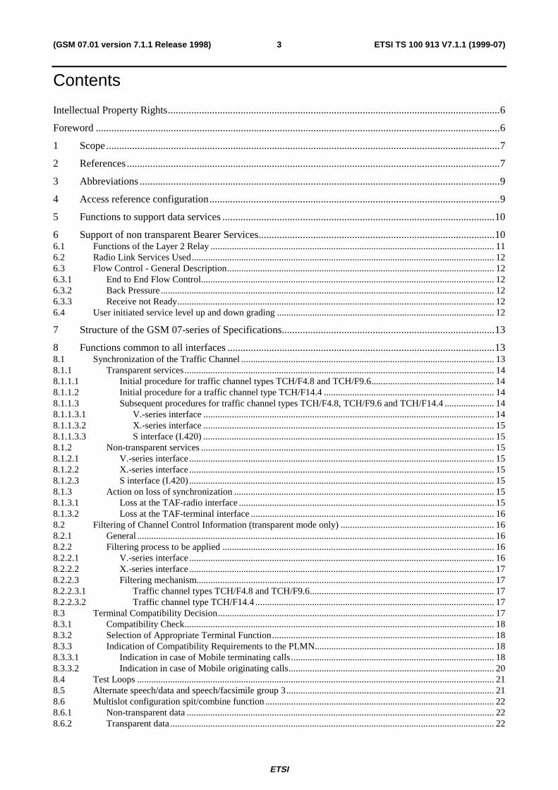
Contents
Intellectual Property Rights................................................................................................................................6
Foreword ............................................................................................................................................................6
1 Scope........................................................................................................................................................7
2 References................................................................................................................................................7
3 Abbreviations ...........................................................................................................................................9
4 Access reference configuration................................................................................................................9
5 Functions to support data services .........................................................................................................10
6 Support of non transparent Bearer Services...........................................................................................106.1 Functions of the Layer 2 Relay ........................................................................................................................ 116.2 Radio Link Services Used................................................................................................................................ 126.3 Flow Control - General Description................................................................................................................. 126.3.1 End to End Flow Control............................................................................................................................ 126.3.2 Back Pressure............................................................................................................................................. 126.3.3 Receive not Ready...................................................................................................................................... 126.4 User initiated service level up and down grading ............................................................................................ 12
7 Structure of the GSM 07-series of Specifications..................................................................................13
8 Functions common to all interfaces .......................................................................................................138.1 Synchronization of the Traffic Channel ........................................................................................................... 138.1.1 Transparent services................................................................................................................................... 148.1.1.1 Initial procedure for traffic channel types TCH/F4.8 and TCH/F9.6.................................................... 148.1.1.2 Initial procedure for a traffic channel type TCH/F14.4 ........................................................................ 148.1.1.3 Subsequent procedures for traffic channel types TCH/F4.8, TCH/F9.6 and TCH/F14.4 ..................... 148.1.1.3.1 V.-series interface ........................................................................................................................... 148.1.1.3.2 X.-series interface ........................................................................................................................... 158.1.1.3.3 S interface (I.420) ........................................................................................................................... 158.1.2 Non-transparent services ............................................................................................................................ 158.1.2.1 V.-series interface................................................................................................................................. 158.1.2.2 X.-series interface................................................................................................................................. 158.1.2.3 S interface (I.420)................................................................................................................................. 158.1.3 Action on loss of synchronization .............................................................................................................. 158.1.3.1 Loss at the TAF-radio interface ............................................................................................................ 158.1.3.2 Loss at the TAF-terminal interface ....................................................................................................... 168.2 Filtering of Channel Control Information (transparent mode only) ................................................................. 168.2.1 General ....................................................................................................................................................... 168.2.2 Filtering process to be applied ................................................................................................................... 168.2.2.1 V.-series interface................................................................................................................................. 168.2.2.2 X.-series interface................................................................................................................................. 178.2.2.3 Filtering mechanism.............................................................................................................................. 178.2.2.3.1 Traffic channel types TCH/F4.8 and TCH/F9.6.............................................................................. 178.2.2.3.2 Traffic channel type TCH/F14.4 ..................................................................................................... 178.3 Terminal Compatibility Decision..................................................................................................................... 178.3.1 Compatibility Check................................................................................................................................... 188.3.2 Selection of Appropriate Terminal Function.............................................................................................. 188.3.3 Indication of Compatibility Requirements to the PLMN............................................................................ 188.3.3.1 Indication in case of Mobile terminating calls...................................................................................... 188.3.3.2 Indication in case of Mobile originating calls....................................................................................... 208.4 Test Loops ....................................................................................................................................................... 218.5 Alternate speech/data and speech/facsimile group 3........................................................................................ 218.6 Multislot configuration spit/combine function................................................................................................. 228.6.1 Non-transparent data .................................................................................................................................. 228.6.2 Transparent data......................................................................................................................................... 22

ETSI
ETSI TS 100 913 V7.1.1 (1999-07)4(GSM 07.01 version 7.1.1 Release 1998)
Annex A (Informative): List of Bearer Capability Elements .............................................................23
Annex B (Normative): Setting of Bearer Capability, Low Layer Compatibility and HighLayer Compatibility Information Element for GSM Bearer Servicesand GSM TeleServices ..................................................................................30
B.0 Scope......................................................................................................................................................30
B.1 Bearer Capability Information Element .................................................................................................30B.1.1 Introduction...................................................................................................................................................... 30B.1.1.1 General Consideration................................................................................................................................ 30B.1.1.2 Interpretation of the Diagrams.................................................................................................................... 31B.1.2 Bearer Service 20 ... 26, Data Circuit Duplex Asynchronous.......................................................................... 41B.1.2.1 Unrestricted / restricted digital information transfer capability.................................................................. 41B.1.2.2 3.1 kHz audio ex-PLMN information transfer capability........................................................................... 43B.1.3 Bearer Service 30 ... 34, Data Circuit Duplex Synchronous ............................................................................ 44B.1.3.1 Unrestricted digital information transfer capability.................................................................................... 44B.1.3.1.1 Non-X.32 Cases.................................................................................................................................... 45B.1.3.1.2 X.32 Case (Packet Service) .................................................................................................................. 46B.1.3.1.3 48kbit/s and 56 kbit/s transparent Case ................................................................................................ 48B.1.3.1.4 64kbit/s bit transparent Case................................................................................................................. 49B.1.3.2 3.1 kHz audio ex-PLMN information transfer capability........................................................................... 50B.1.3.2.1 Non-X.32 Cases.................................................................................................................................... 50B.1.3.2.2 X.32 Case (Packet Service) .................................................................................................................. 51B.1.4 Bearer Service 40 ... 46, PAD Access Asynchronous...................................................................................... 52B.1.5 Bearer Service 50 ... 53 ,Data Packet Duplex Synchronous, Unrestricted digital information transfer
capability.......................................................................................................................................................... 54B.1.6 Bearer Service 61, Alternate Speech/Data ....................................................................................................... 55B.1.6.1 Bearer Service 61,Speech........................................................................................................................... 55B.1.6.2 Bearer Service 61, 3.1 kHz audio ex-PLMN information transfer capability ............................................ 56B.1.6.2.1 Asynchronous ....................................................................................................................................... 56B.1.6.2.2 Synchronous ......................................................................................................................................... 58B.1.7 Bearer Service 81, Speech followed by Data................................................................................................... 59B.1.7.1 Bearer Service 81,Speech........................................................................................................................... 59B.1.7.2 Bearer Service 81, 3.1 kHz audio ex-PLMN information transfer capability ............................................ 59B.1.7.2.1 Asynchronous ....................................................................................................................................... 59B.1.7.2.2 Synchronous ......................................................................................................................................... 59B.1.8 Teleservice 11 ... 12, Speech ........................................................................................................................... 59B.1.9 Teleservice 21 ... 23, Short Message ............................................................................................................... 59B.1.10 Teleservice 61, Alternate Speech and Facsimile group 3................................................................................. 59B.1.10.1 Teleservice 61, Speech............................................................................................................................... 59B.1.10.2 Teleservice 61, Facsimile group 3.............................................................................................................. 60B.1.11 Teleservice 62, Automatic Facsimile group 3.................................................................................................. 60B.1.12 Valid combinations of FNUR, WAIUR, ACC, mTCH.................................................................................... 61B.1.12.1 Transparent Services .................................................................................................................................. 61B.1.12.2 Non-transparent services ............................................................................................................................ 62
B.2 Low Layer/High Layer Compatibility Information Element .................................................................62B.2.1 Introduction...................................................................................................................................................... 62B.2.1.1 General Consideration................................................................................................................................ 62B.2.1.2 Interpretation of the Tables ........................................................................................................................ 63B.2.2 LLC Bearer Service 21 ... 26 ........................................................................................................................... 63B.2.2.1 Unrestricted / restricted digital information transfer capability.................................................................. 63B.2.2.2 3.1 kHz audio ex-PLMN information transfer capability........................................................................... 64B.2.3 LLC Bearer Service 31 ... 34 ........................................................................................................................... 64B.2.3.1 Unrestricted / restricted digital information transfer capability.................................................................. 64B.2.3.2 3.1kHz audio ex-PLMN information transfer capability............................................................................ 65B.2.4 LLC Bearer Services 41 ... 46.......................................................................................................................... 65B.2.5 LLC Bearer Services 51 ... 53.......................................................................................................................... 66B.2.5.1 Unrestricted digital information transfer capability.................................................................................... 66B.2.6 LLC Bearer Service 61 .................................................................................................................................... 66

ETSI
ETSI TS 100 913 V7.1.1 (1999-07)5(GSM 07.01 version 7.1.1 Release 1998)
B.2.6.1 3,1 kHz audio ex-PLMN information transfer capability, Asynchronous .................................................. 66B.2.6.2 3,1 kHz audio ex-PLMN information transfer capability, Synchronous .................................................... 66B.2.7 LLC Bearer Service 81 .................................................................................................................................... 66B.2.7.1 3,1 kHz audio ex-PLMN information transfer capability, Asynchronous .................................................. 66B.2.7.2 3,1 kHz audio ex-PLMN information transfer capability, Synchronous .................................................... 66B.2.8 HLC Teleservices 11 ... 12 .............................................................................................................................. 66B.2.9 HLC Teleservices 21 ... 23 .............................................................................................................................. 67B.2.10 HLC Teleservice 61 ......................................................................................................................................... 67B.2.11 HLC Teleservice 62 ......................................................................................................................................... 67
Annex C (Informative): Change history ...............................................................................................68
History..............................................................................................................................................................69

ETSI
ETSI TS 100 913 V7.1.1 (1999-07)6(GSM 07.01 version 7.1.1 Release 1998)
Intellectual Property RightsIPRs essential or potentially essential to the present document may have been declared to ETSI. The informationpertaining to these essential IPRs, if any, is publicly available for ETSI members and non-members, and can be foundin SR 000 314: "Intellectual Property Rights (IPRs); Essential, or potentially Essential, IPRs notified to ETSI in respectof ETSI standards", which is available free of charge from the ETSI Secretariat. Latest updates are available on theETSI Web server (http://www.etsi.org/ipr).
Pursuant to the ETSI IPR Policy, no investigation, including IPR searches, has been carried out by ETSI. No guaranteecan be given as to the existence of other IPRs not referenced in SR 000 314 (or the updates on the ETSI Web server)which are, or may be, or may become, essential to the present document.
ForewordThis Technical Specification (TS) has been produced by the Special Mobile Group (SMG).
The present document specifies the functions needed for terminal adaptation within the digital cellulartelecommunications system.
The contents of the present document is subject to continuing work within SMG and may change following formal SMGapproval. Should SMG modify the contents of the present document, it will be re-released with an identifying change ofrelease date and an increase in version number as follows:
Version 7.x.y
where:
7 indicates Release 1998 of GSM Phase 2+
x the second digit is incremented for all other types of changes, i.e. technical enhancements, corrections,updates, etc.
y the third digit is incremented when editorial only changes have been incorporated in the specification.

ETSI
ETSI TS 100 913 V7.1.1 (1999-07)7(GSM 07.01 version 7.1.1 Release 1998)
1 ScopeThe present document is based on the principles of terminal adaptor functions presented in the CCITT I-series ofrecommendations (I.460 - I.463).
The GSM PLMN supports a wide range of voice and non-voice services in the same network. In order to enable non-voice traffic in the GSM PLMN there is a need to connect various kinds of terminal equipments to the MobileTermination (MT). The target of this ETS is to outline the functions needed for the terminal adaptation.
In the GSM 02.02 (ETS 300 904) the bearer services are described. The general network configuration is described inGSM 03.02 and the GSM PLMN access reference configuration is defined in GSM 04.02. The various connection typesused in the GSM PLMN are presented in GSM 03.10. Terminology used in this ETS is presented in GSM 01.04(ETR 350). For support of data services between GSM PLMN and other networks see GSM 09-series of Specifications.
2 ReferencesThe following documents contain provisions which, through reference in this text, constitute provisions of the presentdocument.
• References are either specific (identified by date of publication, edition number, version number, etc.) ornon-specific.
• For a specific reference, subsequent revisions do not apply.
• For a non-specific reference, the latest version applies.
• A non-specific reference to an ETS shall also be taken to refer to later versions published as an EN with the samenumber.
• For this Release 1998 document, references to GSM documents are for Release 1998 versions (version 7.x.y).
[1] GSM 01.04: "Digital cellular telecommunication system (Phase 2+); Abbreviations and acronyms".
[2] GSM 02.02: "Digital cellular telecommunication system (Phase 2+); Bearer Services (BS)supported by a GSM Public Land Mobile Network (PLMN)".
[3] GSM 02.03: "Digital cellular telecommunication system (Phase 2+); Teleservices supported by aGSM Public Land Mobile Network (PLMN)".
[4] GSM 03.02: "Digital cellular telecommunication system (Phase 2+); Network architecture".
[5] GSM 03.10: "Digital cellular telecommunication system (Phase 2+); GSM Public Land MobileNetwork (PLMN) connection types".
[6] GSM 04.02: "Digital cellular telecommunication system (Phase 2+); GSM Public Land MobileNetwork (PLMN) access reference configuration".
[7] GSM 04.08: "Digital cellular telecommunication system (Phase 2+); Mobile radio interface layer 3specification".
[8] GSM 04.21: "Digital cellular telecommunication system (Phase 2+); Rate adaption on the MobileStation - Base Station System (MS - BSS) interface".
[9] GSM 04.22: "Digital cellular telecommunication system (Phase 2+); Radio Link Protocol (RLP)for data and telematic services on the Mobile Station - Base Station System (MS - BSS) interfaceand the Base Station System - Mobile-services Switching Centre (BSS - MSC) interface".
[10] GSM 05.05: "Digital cellular telecommunication system (Phase 2+); Radio transmission andreception".
[11] GSM 07.02: "Digital cellular telecommunication system (Phase 2+); Terminal AdaptationFunctions (TAF) for services using asynchronous bearer capabilities".

ETSI
ETSI TS 100 913 V7.1.1 (1999-07)8(GSM 07.01 version 7.1.1 Release 1998)
[12] GSM 07.03: "Digital cellular telecommunication system (Phase 2+); Terminal AdaptationFunctions (TAF) for services using synchronous bearer capabilities".
[13] GSM 07.05: "Digital cellular telecommunication system (Phase 2+); Use of Data TerminalEquipment - Data Circuit terminating Equipment (DTE - DCE) interface for Short MessageService (SMS) and Cell Broadcast Service (CBS)".
[14] GSM 07.07: "Digital cellular telecommunication system (Phase 2+); AT command set for GSMMobile Equipment (ME)
[15] GSM 09.01 (ETR 359): "Digital cellular telecommunication system (Phase 2); General networkinterworking scenarios".
[16] GSM 09.02: "Digital cellular telecommunication system (Phase 2+); Mobile Application Part(MAP) specification".
[17] GSM 09.03: "Digital cellular telecommunication system (Phase 2+); Signalling requirements oninterworking between the Integrated Services Digital Network (ISDN) or Public SwitchedTelephone Network (PSTN) and the Public Land Mobile Network (PLMN)".
[18] GSM 09.04: "Digital cellular telecommunication system (Phase 2+); Interworking between thePublic Land Mobile Network (PLMN) and the Circuit Switched Public Data Network (CSPDN)".
[19] GSM 09.05: "Digital cellular telecommunication system (Phase 2+); Interworking between thePublic Land Mobile Network (PLMN) and the Packet Switched Public Data Network (PSPDN) forPacket Assembly/Disassembly (PAD) facility access".
[20] GSM 09.06: "Digital cellular telecommunication system (Phase 2+); Interworking between aPublic Land Mobile Network (PLMN) and a Packet Switched Public Data Network/IntegratedServices Digital Network (PSPDN/ISDN) for the support of packet switched data transmissionservices".
[21] GSM 09.07: "Digital cellular telecommunication system (Phase 2+); General requirements oninterworking between the Public Land Mobile Network (PLMN) and the Integrated ServicesDigital Network (ISDN) or Public Switched Telephone Network (PSTN)".
[22] GSM 09.08: "Digital cellular telecommunication system (Phase 2+); Application of the BaseStation System management Application Part (BSSMAP) on the E-interface".
[23] GSM 09.10: "Digital cellular telecommunication system (Phase 2+); Information element mappingbetween Mobile Station - Base Station System and BSS - Mobile-services Switching Centre (MS -BSS - MSC) Signalling procedures and the Mobile Application Part (MAP)".
[24] GSM 09.11: "Digital cellular telecommunication system (Phase 2+); Signalling interworking forsupplementary services".
[25] GSM 09.90: "Digital cellular telecommunication system (Phase 2+); Interworking between Phase 1infrastructure and Phase 2+ Mobile Stations (MS)".
[26] CCITT Series V Recommendations: "Data communication over the Telephone network".
[27] CCITT Series V.42bis: "Data Compression for Data Circuit Terminating Equipment (DCE) usingError Correction Procedures".
[28] CCITT Series X Recommendations: "Data Communication networks”.
[29] CCITT Recommendation X.25 "Interface between data terminal equipment (DTE) and data circuit- terminating equipment (DCE) for terminals operating in the packet mode and connected to publicdata networks by dedicated circuit".
[30] CCITT Recommendation X.150: "Data Communication Networks: Transmission, Signalling andSwitching, Network Aspects, Maintenance and Administrative Arrangements".
[31] CCITT Recommendation V.25bis: "Automatic Calling and/or Answering Equipment on theGeneral Switched Telephone Network (GSTN) using the 100-Series Interchange Circuits".

ETSI
ETSI TS 100 913 V7.1.1 (1999-07)9(GSM 07.01 version 7.1.1 Release 1998)
[32] ITU-T Recommendation V.25ter: "Serial asynchronous automatic dialing and control".
[33] CCITT Recommendation V.54: "Loop Test Devices for Modems".
[34] CCITT Recommendation V.110: "Support of data terminal equipments (DTEs) with V-Seriesinterfaces by an integrated services digital network".
[35] CCITT Recommendation I.460-I.464: "ISDN Overall Network Aspects and Functions, UserNetwork Interfaces".
[36] ETS 300 102-1: "Integrated Services Digital Network (ISDN); User-network interface layer 3specifications for basic call control".
[37] ETR 018: "Integrated Services Digital Network (ISDN), Application of the BC-, HLC-, LLC-Information elements by terminals supporting ISDN services".
[38] ISO/IEC 6429: "Information technology - Control functions for coded character sets".
[39] Personal Computer Memory Card Association: "PCMCIA 2.1 or PC-Card 3.0 electricalspecification or later revisions".
[40] IrDA "IrPHY Physical signalling standard".
[41] TIA-617: "Data Transmission Systems and Equipment - In-Band DCE Control".
[42] CCITT Recommendation V.120: "Support by an ISDN of data terminal equipment with V-Seriestype interfaces with provision for statistical multiplexing".
[43] GSM 03.34:”Digital cellular telecommunication system (Phase 2+); High Speed Circuit SwitchedData (HSCSD); Stage 2 Service description”.
3 AbbreviationsIn addition to those below, abbreviations used in the present document are listed in GSM 01.04.
CALL PROC CALL PROCEEDINGCALL CONF CALL CONFIRMEDCONNACK CONNECT ACKNOWLEDGEMENT
4 Access reference configurationFigure 1 presents the reference configuration for access to a GSM PLMN (see GSM 04.02).
MS :<••••••••••••••••••••••••••••••••••••>: : ••••••••• : ••••••••••••• : • MT0 ••••••• BSS/MSC • : ••••••••• : ••••••••••••• : ••••••••• ••••••••• : ••••••••••••• : • TE1 ••••••• MT1 ••••••• BSS/MSC • : ••••••••• : ••••••••• : ••••••••••••• ••••••••• ••••••••• : ••••••••• : ••••••••••••• • TE2 ••••••• TA ••••••• MT1 ••••••• BSS/MSC • ••••••••• : ••••••••• : ••••••••• : ••••••••••••• ••••••••• : : ••••••••• : ••••••••••••• • TE2 ••••••••••••••••••••• MT2 ••••••• BSS/MSC • ••••••••• : : ••••••••• : ••••••••••••• : : : R S Um
••• = reference point
TE1 = ISDN terminal

ETSI
ETSI TS 100 913 V7.1.1 (1999-07)10(GSM 07.01 version 7.1.1 Release 1998)
TE2 = V- or X-type terminal
TA = Terminal Adaptor
BSS = Base Station System
MSC = Mobile Switching Centre
Figure 1: GSM PLMN Access Reference Configuration
Within the scope of this TS the Mobile Termination MT0 means a fully integrated MS including data terminal and itsadaptation functions. MT1 includes ISDN terminal adaptation functions and MT2 includes CCITT V- or X-seriesterminal adaptation functions among other MT functions.
5 Functions to support data servicesThe main functions of the MT to support data services are:
- functions to ensure conformity of terminal service requests to network capability;
- physical connection of the reference points R and S;
- flow control of signalling and mapping of user signalling to/from GSM PLMN access signalling;
- rate adaptation of user data (see GSM 04.21);
- flow control of non-transparent user data and mapping of flow control for asynchronous data services;
- support of data integrity between the MS and the interworking function in the GSM PLMN;
- end-to-end synchronization between terminals;
- filtering of status information;
- functions to support non-transparent bearer services e.g. termination of the Radio Link Protocol (RLP) and theLayer 2 Relay function (L2R) including optional data compression function (where applicable);
- terminal compatibility checking;
- optional support of local test loops.
In addition, functions to support autocalling and autoanswering are optionally specified in accordance with CCITT Rec.V.25 bis or with ITU-T Reccomendation. V.25 ter (although the use of other autocalling/auto-answering procedures arenot prohibited provided that mapping in a functionally equivalent way to GSM 04.08 call control is also provided).
Other functional entities can be envisaged apart from the TAF. One of the physical interface to all these functions is theDTE/DCE interface to the MT. Normally, this DTE/DCE interface is associated with the TAF, if available. Thereforethe access to any of these other functional entities, if implemented, via the DCE/DTE interface must be triggered byappropriate command sequences which are described in the applicable specifications (although the use of otherprocedures is not prohibited provided that mapping in a functionally equivalent way is also provided). These commandsequences can be issued by the DTE only when the MT is in the appropriate command status and there is no dataconnection pending. They are interpreted by an MT internal control function and result in an association of theDTE/DCE interface with the addressed function, if available.
6 Support of non transparent Bearer ServicesIn order to support non transparent bearer services a Layer 2 Relay (L2R) function is included in the mobile termination.The details of the particular L2R function for the different non transparent bearer services are contained in theappropriate GSM 07-series Specification. This section describes the general aspects of the L2R function.

ETSI
ETSI TS 100 913 V7.1.1 (1999-07)11(GSM 07.01 version 7.1.1 Release 1998)
The Layer 2 Relay (L2R) function provides for the reliable transportation of known, i.e. non transparent, user protocolsacross the radio interface of a GSM PLMN. The L2R functions are located in the Mobile Termination (MT) and theInterworking Function (IWF) associated with a Mobile Switching Centre (MSC). The L2R uses the services provided bythe Radio Link Protocol (RLP) to transport the non transparent protocol information between the MS and the IWF.
6.1 Functions of the Layer 2 RelayThe complete protocol reference models for data and telematic services are described in GSM 03.10. The subset ofthose protocol reference models relating to the L2R function is reproduced in figure 2.
MS IWF
••••••••••••• Transparent higher layer protocol •••••••••••••
••••••••••• ••••••••••• • L2R •••••• L2R Protocol ••••• L2R •• NTP ••• ••••••• ••••••• ••• NTP •• • • • •• Radio Link Protocol •• • • • ••••• ••••• ••••• •••••• IFP ••• • • ••• IFP •• ••••• •••••
NTP Non Transparent ProtocolIFP Interface Protocol
Figure 2
The Non Transparent Protocol (NTP) will normally be a layer 2 protocol for OSI conformant protocols or an equivalentin the case of non OSI protocols. The Interface Protocol (IFP) will normally be a layer 1 protocol for OSI conformantsystems or equivalent for non OSI systems.
The L2R can be considered to consist of 3 sub-functions, see figure 3.
•••••••••••••••••••••••••••••• • • • Relay Entity • • •••••••••••• • • • L2RP • ••••••••••• NTP Entity • • Entity •••••••••••••••••• • • • • • • • RLP • • • • Entity • •••••••••••••
Figure 3
The 3 sub-functions are:
- A Non Transparent Protocol Entity
- A L2R Protocol Entity
- A Relay Entity
The NTP-entity interfaces the L2R to the IFP-entity and provides an interface to the particular NTP.
The L2RP-entity interfaces the L2R to the RLP-entity and provides an interface to the appropriate L2R protocol.
The Relay-entity provides the mapping between the NTP-entity and the L2R-entity. If applicable, it contains the datacompression function. The negotiable parameters are exchanged with the remote Relay-entity by means of the RLP XIDframe.
It should be noted that the inter-layer interfaces within the MS and the IWF and within the L2R will not be specified byGSM, any description given is for explanatory purposes only and is not intended to indicate a method ofimplementation. Therefore, the specification of the L2R is in terms of the peer-peer protocols. Generally, the non

ETSI
ETSI TS 100 913 V7.1.1 (1999-07)12(GSM 07.01 version 7.1.1 Release 1998)
transparent and interface protocols will be specified elsewhere, e.g. CCITT Recommendation X.25 Layer 2 and 1. Thusthe main specification for the L2R will consist of the L2R peer-peer protocols.
6.2 Radio Link Services UsedThe L2R function uses services defined in GSM Specification 04.22 (Radio Link Protocol).
6.3 Flow Control - General DescriptionA flow control active condition can take place under a number of circumstances:
- End to end flow control (DTE to DTE matter);
- Backpressure (buffers filling);
- Receive not ready (RLP condition).
It is possible that there will be an interaction between flow control active and inactive conditions in each circumstance.
6.3.1 End to End Flow Control
A DTE may wish to send a flow control active condition to another DTE.
Provisions exists in the L2R entity to transfer a flow control active condition (sent by its associated DTE) to the otherL2R entity as soon as possible. This mechanism in the L2R entities allows such a flow control condition to be put aheadof any queuing which exists in the L2R entities.
Such a mechanism avoids build up of data in buffers which can be undesirable.
The L2R entity, receiving a flow control active condition from its associated DTE, stops sending data to that associatedDTE immediately.
6.3.2 Back Pressure
The L2R and RLP entities have buffers which may become full to a predetermined threshold for a number of reasons,e.g. severe radio fading, failure or slowness of DTE to react to end to end flow control, certain RNR conditions. Whenthis predetermined threshold is reached, a flow control active condition is sent to the associated DTE which is thenprevented from sending any data, subsequently, the flow control inactive condition is sent to the associated DTE whenthe L2R or RLP entities have indicated that there is sufficient free capacity in their buffers for data flow from theassociated DTE to proceed.
The corresponding peer-layer procedure to assess the respective buffer conditions are a layer management matter andare not dealt with here. It is also considered an implementation matter to ensure that such procedure do not result in lossof data or considerable reduction in throughput.
6.3.3 Receive not Ready
When the RNR condition arises, an RLP indication is sent to the other RLP entity which in turn shall send a flow controlactive condition to its associated L2R entity. That L2R entity shall then send a flow control active condition to itsassociated DTE.An RNR condition may result in the Execution of "back pressure" as mentioned under 6.3.2.
6.4 User initiated service level up and down gradingWhen the value of the negotiated UIMI parameter is greater than 0, the MS may at any time during the call, control, tosome extent, the number of traffic channels to be used. This is done by signalling a higher or lower value for the wantedair interface user rate (WAIUR) and maximum number of traffic channels (mTCH). The network will assign an AIUR

ETSI
ETSI TS 100 913 V7.1.1 (1999-07)13(GSM 07.01 version 7.1.1 Release 1998)
matching the WAIUR using up to mTCH traffic channels, provided that the resources are available (GSM TS 02.34,03.34, 04.08).
If the value of the RLP optional feature ‘Up signalling’ is negotiated to 1, the MS may receive a suggestion from thenetwork to initiate an upgrading. This occurs when the following condition holds:
The IWF
1) is receiving user data from the fixed network side at a higher rate than the current AIUR, or,
2) in symmetrical calls only, can send user data towards the fixed network side at a higher rate than the currentAIUR.
The MS can detect the condition stated in 1) and 2) above by examining the value of the UP bit in the received RLP Sand I+S frames. When the condition does not hold, the value of the UP bit is continuously 0. If the condition does hold,the number of 1s between two consecutive 0s indicates the number of traffic channels to upgrade by. There is no need torepeat this indication since the FCS protects it. For instance, if the UP bit sequence is ...01100... and the current numberof assigned traffic channels is 2, then an upgrading to 4 traffic channels is suggested.
The MS may use the information signalled in the UP bit to find out when a service level upgrading may increase the datathroughput. In order to initiate a service level upgrading, the value of UIMI must be greater than the number of currentlyassigned channels.
In order to determine when to downgrade, the MS may compare the rate of received and sent information in the RLPframes to the AIUR. If the rate of received and sent information is less than the current AIUR the MS may initiate adowngrading.
7 Structure of the GSM 07-series of SpecificationsThe structure of the Specifications is as follows:
07.01 General on Terminal Adaptation Functions for Mobile Stations
07.02 Terminal Adaptation Functions for Services using Asynchronous Bearer Capabilities
This Specification defines the interfaces and terminal adaption functions integral to a MT whichenable the attachment of Asynchronous Terminals to a MT.
07.03 Terminal Adaptation Functions for Services using Synchronous Bearer Capabilities
This Specification defines the interfaces and terminal adaptation functions integral to a MT whichenable the attachment of Synchronous Terminals to a MT.
8 Functions common to all interfaces
8.1 Synchronization of the Traffic ChannelAs long as there is no connection between the traffic channel and the interface to the TE this interface must beterminated in the appropriate way.
Prior to exposing the traffic channel of a GSM PLMN connection to transmission of user data, the controlling entities ofthe connection have to assure of the availability of the traffic channel(s). This is done by the so called synchronizationprocess:
- starting on the indication of "physical connection established" resulting from the PLMN inherent outbandsignalling procedure. This indication is given on reception of the message CONNECT in case of MOC, onreception of the message CONNACK in case of MTC and on reception of the message MODIFY COMPLETE incase of in-call modification;

ETSI
ETSI TS 100 913 V7.1.1 (1999-07)14(GSM 07.01 version 7.1.1 Release 1998)
- ending by indicating the successful execution of this process to the controlling entity, which then takes care of thefurther use of the inband information (data, status).
It should be noted that during the call control phases (set-up and clear), the procedures at the V.-series and X.-seriesDTE interfaces can be mapped completely to the out-of-band signalling procedure. The state of the S-bits and X-bitsduring the call control phases are irrelevant to the DTE interface procedures. However, the "ready for data" condition(i.e. CTs 106 and 109, in the case of V.-series interface, and I-circuit, in the case of X.-series interface) is derived fromthe status bits received by the TAF once synchronization is complete. Since half duplex operation is not supported by aGSM PLMN, status bit SB is not needed to signal the turn around of the connection.
8.1.1 Transparent services
8.1.1.1 Initial procedure for traffic channel types TCH/F4.8 and TCH/F9.6
With respect to the TAF for the transparent bearer capability support the synchronization procedure with the channelcodings 2.4, 4.8 and 9.6 kbit/s is as follows:
- sending of synchronization pattern 1/OFF (all data bits "1" / all status bits "OFF", all E-bits "1") to the IWF. Inmultislot transparent operation, the synchronisation pattern sent is 1/OFF with the exception of the bit positionsS1, first X, S3, and S4 which contain the substream number and multiframe alignment pattern (Ref. GSM TS04.21);
- searching for detection of the synchronization pattern received from the IWF, and in multislot operation, alsosearching for the multiframe alignment pattern “0000 1001 0110 0111 1100 0110 1110 101” (Ref. to GSM04.21) in bit position S4 and substream numbers in bit positions S1, first X, and S3. The value of the bits E4-E7shall not be checked;
8.1.1.2 Initial procedure for a traffic channel type TCH/F14.4
With respect to the TAF for the transparent bearer capability support the procedure with the TCH/F14.4 is as follows:- sending of synchronization pattern 1/OFF (all data bits "1" / status bits in M2 "OFF") to the network in the
multiframe structure with the multiframe alignment pattern “0000 1001 0110 0111 1100 0110 1110 101” in theM1 (Ref. to GSM TS 4.21) and, in a multislot case, sending substream numbers in the bit M2
- searching for the detection of the multiframe alignment pattern “0000 1001 0110 0111 1100 0110 1110 101”(Ref. to GSM 04.21) in the bit M1 originating from the network, and, in a multislot case, searching for substreamnumbers in the bit M2. (Any 5 bit sequence in the multiframe alignment pattern is unique, i.e. the multiframealignment can take place by the recognition of five successive S1 bits.)
8.1.1.3 Subsequent procedures for traffic channel types TCH/F4.8, TCH/F9.6 andTCH/F14.4
When the synchronisation pattern and, in case of multislot operation or TCH/F14,4, the multiframe alignment patternfrom the IWF have been recognized as a steady state (see note) the TAF continues sending the synchronization patternsto the IWF until a timer T (=500ms) expires.
NOTE: - An idle frame sent by the BSS and received by the MS has the same pattern as the synchronizationpattern 1/OFF.
- At the moment when the message CONNECT (MOC) or CONNACK (MTC) is received at the MS, it isguaranteed that this pattern is received from the MSC/IWF with the exception of a loss of framesynchronization on the Abis interface.
- The handling of frame stealing in case of 2400 bit/s full rate data channels is implementation dependent.
8.1.1.3.1 V.-series interface
During the synchronization process described above, i.e. while the synchronization pattern is being sent by the MT,CT106, 107 and 109 remain in the OFF condition.

ETSI
ETSI TS 100 913 V7.1.1 (1999-07)15(GSM 07.01 version 7.1.1 Release 1998)
After the expiration of the timer T of each allocated traffic channel for the call, the X and SB bits received from the IWFare mapped on to CT 106 and CT 109, respectively, at the MT/DTE interface according to the filtering processdescribed in section 8.2. The received SA bit, if available, is ignored. The condition on CT107 is changed from "OFF"to "ON", the data bits received from the IWF are mapped to CT104, and CT103 is mapped to the data bits sent towardsthe IWF. The transmitted SA (if available), SB and X bits shall be set to "ON".
8.1.1.3.2 X.-series interface
The procedure is described in GSM 07.03, "X.21 procedures mapping".
8.1.1.3.3 S interface (I.420)
During the synchronization process described above, i.e. while the synchronization pattern is being sent by the MT, theMT will not send the V.110 frame structure to the S interface. Once the timer T of each traffic channel(s) allocated forthe call expires the synchronization pattern will continue to be transmitted from the MT to the IWF, however, the MTwill start sending the frames received from the IWF to the S interface. The MT will start looking for the V.110 framealignment to be received from the S interface. On recognizing frame alignment the MT will cease sending itssynchronization pattern to the IWF and connect the S interface through to the IWF. In case of multislot operation orTCH/14.4 the MT shall adapt the data stream as defined in GSM TS 04.21.
8.1.2 Non-transparent services
With respect to the TAF for non-transparent bearer capability support the synchronization procedure is as follows:
- firstly, receiving frames on all allocated traffic channels for the call
- secondly, initiating the RLP link establishment by sending a RLP-SABM across the radio interface.
8.1.2.1 V.-series interface
During the synchronization process described above, i.e. while the synchronization pattern is being sent by the MT,CT106, 107 and 109 remain in the OFF condition.
When the RLP link has been established, CT107 will be changed from "OFF" to "ON". From this time the informationfrom/to the RLP, including status changes, will be mapped by the L2R entity applicable to the particular bearercapability (GSM 07.02, 07.03 "L2R functionality").
8.1.2.2 X.-series interface
The procedure is described in GSM 07.03, "X.21 procedures mapping".
8.1.2.3 S interface (I.420)
The MT will not send V.110 frame structure to the S interface and will not start looking for V.110 frame alignment to bereceived from the S interface unless the RLP link has been established. On recognizing V.110 frame alignment theinformation from/to the RLP will be mapped by the L2R entity.
8.1.3 Action on loss of synchronization
8.1.3.1 Loss at the TAF-radio interface
If the TAF detects a loss of synchronisation on one or more channels, it initiates the re-synchronisation process. TheTAF searches for the data frame structure in those channels in which the synchronisation has been lost according to inthe initial procedures described in section 8.1.1.1 (TCH/F4.8 and TCH/F9.6) and section 8.1.1.2 (TCH/F14.4). Theinformation received from the channels shall continue to be processed as if the synchronisation had not been lost, i.e.corrupted data is forwarded towards RLP entity or TE during the re-synchronisation process. No action shall be taken onthe frames being transmitted towards the MSC, other than to continue sending them normally.
ETSI
ETSI TS 100 913 V7.1.1 (1999-07)16(GSM 07.01 version 7.1.1 Release 1998)
8.1.3.2 Loss at the TAF-terminal interface
This section is applicable only to terminals attached by means of an S interface (I.420).If the TAF detects a loss of frame synchronisation on the TAF-TE interface, the TAF initiates a re-synchronisation onthat link in line with the procedures specified in CCITT V.110. No further action shall be taken by the TAF on theTAF-radio interface or on the V.110 frames being transmitted towards the TE.
8.2 Filtering of Channel Control Information (transparent modeonly)
8.2.1 General
The DTEs used at the MS side of the PLMN conform to CCITT's DTE/DCE interface specifications, which assumebasically an error-free environment, i.e.
- limited distance, point-to-point local interconnection of the interface circuits for data and status;
- steady state signalling.
The envisaged use of these DTEs in the PLMN environment leads to the exposure of these "interconnections" to thePLMN radio channel. To assure proper operation even under these conditions appropriate measures have to be taken. Inthe non transparent case the RLP satisfies the requirement for both data and status lines.
In the transparent case the
- data line aspects have to be dealt with end-to-end by the users, while
- status line aspects are of concern to the network, and are dealt with in the following.
8.2.2 Filtering process to be applied
Filtering of channel control information is relevant only at the MS side and in the transparent mode of operation. Byapplying filtering measures the condition of a DTE/DCE control interchange circuit, for which the DTE constitutes theinformation sink, will be preserved until another condition is signalled for an "integration time" period by the channelcontrol information (status bits) of the rate adaptation scheme.
The filtering mechanism is understood to reside between the rate adaptation function (information source) and the DTE(information sink). It receives the unfiltered condition of the respective control interchange circuit set according to theactual sequential appearance of the individual associated status bits and forwards the filtered condition to the DTE.
The filtering process starts when the traffic channel synchronization ends with the expiry of timer T.
8.2.2.1 V.-series interface
CT 106
In the transparent mode the remote inband control of this circuit is needed to support a modem retrain procedure.
OFF-ON transition at the MS will authorize the DTE to send data; if wrongly set, loss of data may occur.
ON-OFF transition at the MS will cause the DTE to cease transmitting data; set wrongly may impair the performance inconnection usage.
CT 109
In the transparent mode the remote inband control of this circuit is needed to:
- trigger the interpretation of received data;
- indicate to the DTE the state of the connection.

ETSI
ETSI TS 100 913 V7.1.1 (1999-07)17(GSM 07.01 version 7.1.1 Release 1998)
OFF-ON transition at the MS will authorize the DTE to rely on the condition of the received data interchange circuit, setwrongly may cause receipt of wrong data, while setting late may cause loss of data.
ON-OFF transition at the MS:
- will cause the DTE to cease receiving data;
- may initiate release of the connection during a data phase by the DTE giving an ON-OFF transition on circuit108/2.
Setting this condition wrongly may cause loss of data and potentially release the connection.
8.2.2.2 X.-series interface
I-circuit
The OFF-ON transition of this circuit in connection with the appropriate conditions of the other interchange circuit willindicate the "ready for data" status of the connection. As received data may commence immediately following this statuschange, the delay in conveying this condition shall be kept as short as possible.
As a clear request/indication will be directly mapped to the PLMN outband signalling the ON-OFF integration timeshould be rather long.
8.2.2.3 Filtering mechanism
8.2.2.3.1 Traffic channel types TCH/F4.8 and TCH/F9.6
A filtering mechanism shall be provided by an integration process on those SB and X bits carrying status information inthe V.110 frame or in the multiframe structure. The integration periods applied are:
V-series Transition Integration Statusperiod stream
CT 106 Off-On 1 s XCT 106 On-Off 1 s XCT 109 Off-On 200 ms SBCT 109 On-Off 5 s SB
X-series Transition Integration Statusperiod stream
I-circuit Off-On 40 ms SBI-circuit On-Off 5 s SB
The integration process shall ensure that the interchange circuits do not change state in response to spurious transitionsof the status bits during the integration period.
The integration process shall operate reliably with error characteristics as specified in GSM 05.05.
8.2.2.3.2 Traffic channel type TCH/F14.4
To change the state of CT 109 (or I-circuit) or CT 106, it is required that at least two consecutive SB-bits or X-bits,respectively, carry the same value.
8.3 Terminal Compatibility DecisionThe establishment of a mobile terminated connection depends on a positive decision on the terminal compatibility. TheMobile Station (MS) contributes to this process by performing (depending on the individual call set-up condition):
- a compatibility check;

ETSI
ETSI TS 100 913 V7.1.1 (1999-07)18(GSM 07.01 version 7.1.1 Release 1998)
- the selection of the appropriate terminal function; and
- the indication of compatibility requirements to the PLMN;
initiated by a call set-up request from the PLMN. The aforementioned functions shall be carried out as follows.
8.3.1 Compatibility Check
Annex B of GSM 04.08 applies, particularly paragraphs B.3, B.3.1 and B.3.2. As regards the therein mentioned user-to-user compatibility checking the following applies:
When the calling user requests a service with user-to-user compatibility significance indicated by the presence of HLCand LLC information element in the call set-up request, the MS shall check that the service supported by the called usermatches concerning the contents of the HLC/LLC information element. If a mismatch is detected, then the MS shallreject the offered call using the cause No.88 "Incompatible Destination".
8.3.2 Selection of Appropriate Terminal Function
The MS shall select the appropriate terminal functions following a positive result of the compatibility check and/orforwarding the indication of compatibility requirements to the PLMN.
8.3.3 Indication of Compatibility Requirements to the PLMN
8.3.3.1 Indication in case of Mobile terminating calls
In support of:
- PSTN originated calls, and
- ISDN originated calls using 3.1 kHz audio Bearer Capability (BC), as well as
- ISDN originated calls using unrestricted digital Bearer Capability but not specifying all parameters for deducinga Bearer Service.
Mobile specific requirements to be dealt with in the Bearer Capability information element the call confirmed messagehas been introduced in the call control protocol (GSM 04.08). This also allows for renegotiation of specific parametersat the beginning of the connection set-up process. The specific parameters are:
a) mobile specific requirements:
- Connection element (transparent/non transparent);
- Structure (note 1);
- User information layer 2 protocol (note 1);
- Intermediate rate (note 2), (note 3);
- Modem Type (note 1), (note 3);
- User Rate (note 3);
- Compression ,
- Fixed network user rate, (note 3) (note 4)
- Other modem type, (note 3) (note 4)
- User initiated modification indication(note 4)
The following parameters are indicated by the MS to the network, only:
- Acceptable channel codings (note 5)

ETSI
ETSI TS 100 913 V7.1.1 (1999-07)19(GSM 07.01 version 7.1.1 Release 1998)
- Maximum number of traffic channels, (note 5)
- Wanted air interface user rate (note 6)
NOTE 1: This parameter is correlated with the value of the parameter connection element.
NOTE 2: For non-transparent services this parameter is correlated with the value of the parameter negotiation ofintermediate rate requested.
NOTE 3: Modification of these parameters may be proposed by the MS. The Network may accept it or not.
NOTE 4: This parameter shall be included by the MS only in case it was received from the network.
NOTE 5: This parameter shall be included only in case the parameter ‘fixed network user rate’ is included.
NOTE 6: This parameter shall be included only for non-transparent services and in case the parameter ‘fixednetwork user rate’ is included.
b) requirements with effects at the partner terminal:
- Number of data bits;
- Number of stop bits;
- Parity.
The MS indicates the radio channel requirement in the call confirmed message. If the MS indicates the support of "dual"(HR and FR channels) the final decision, which radio channel is chosen, is done by the network in an RR message.
If the network proposes optional support of both transparent and non transparent connection elements but does notindicate a user information layer 2 protocol, the MS shall set the appropriate value, if choosing non transparent in thecall confirmed message and out-band flow control is not requested.
Additionally the values of the parameters structure, modem type and intermediate rate have to be set in conformancewith the values of the parameters radio channel requirements, negotiation of intermediate rate requested and connectionelement.
Section B.1.1.2 and table B.1 in the annex B describe the negotiation procedure. Annex B table B.4 describes theselection of the modem type and the dependence on the value of the parameter connection element. Annex B table B.4describes the selection of the intermediate rate and user rate and their dependence upon the value of the NIRR parameterand the equipment capabilities.
The following MTC cases can be deduced from the individual call set-up request conditions
a) If the set-up does not contain a BC information element, the MS in the call confirmed message shall include anyBC information (single or multiple BC-IE). In case of multiple BC-IEs one BC-IE must indicate the informationtransfer capability "speech".
b) If the set-up message contains a single BC-IE, the MS in the call confirm message shall use either a single BC-IE,if it wants to negotiate mobile specific parameter values, or, unless otherwise specified in annex B, no BC-IE, if itagrees with the requested ones.
c) If the set-up contains a multiple BC-IE, the MS in the call confirmed message shall use either a multiple BC-IE,if it wants to negotiate mobile specific parameter values, or, unless otherwise specified in annex B, no BC-IE, if itagrees with the requested ones. Alternatively a single BC-IE containing fax group 3 only shall be used if amultiple BC-IE requesting speech alternate fax group 3 is received and the MS is not able to support the speechcapability. Annex B, table B.7, describes the negotiation rules.
If the BC-IE contains 3.1 kHz ex PLMN, the MS is allowed to negotiate all mobile specific parameter values listedabove. If the BC-IE contains facsimile group 3, the MS is allowed to negotiate the connection element (transparent/nontransparent) only. In any case, if the set-up message requests a "single service", the MS must not answer in the callconfirmed message requesting a "dual service" and vice versa.

ETSI
ETSI TS 100 913 V7.1.1 (1999-07)20(GSM 07.01 version 7.1.1 Release 1998)
However, for dual services with repeat indicator set to circular (alternate) the MS may change the sequence of dual BC-IEs within the call confirmed message (preceded by the same value of the repeat indicator), if it wants to start with adifferent Bearer Capability than proposed by the network as the initial one.
In addition, the MS may propose to the network to modify User Rate, Modem Type and Intermediate Rate in the CALLCONFIRMED message. The network may accept or release the call.
If the BC-IE received from the network contains the parameters ‘fixed network user rate’, ‘other modem type’ andpossibly the ‘user initiated modification’, the MS can either:
a) discard these parameters, or
b) include the possibly modified values for the ‘fixed network user rate’ and ‘other modem type’ in the BC-IE of thecall confirmed message. The network might accept or reject the modified values. In this case the MS shall alsoinclude the parameters ‘maximum number of traffic channels’ and ‘acceptable channel codings’. Additionally fornon-transparent services, the MS shall also include the parameters ‘wanted air interface user rate’ and the ‘userinitiated modification indication‘.
In case a),The MS shall use the fall-back bearer service indicated by the remaining parameters of the BC-IE on a singleslot configuration (reference GSM 04.21).
In case b), a single slot configuration shall be used by the MS, in case the ‘maximum number of traffic channels’ is set to“1 TCH“ and the ‘user initiated modification indication’ is set either to “user initiated modification not required” or to“user initiated modification up to 1TCH may be requested”; other wise the MS shall use a multislot configuration(reference GSM 04.21).
In case the ‘acceptable channel codings’ is indicated by the MS, the decision which channel coding is used is done bythe network and indicated to the mobile station with an RR message. The ‘acceptable channel codings’ parameter takesprecedence over the ‘negotiation of intermediate rate requested’ parameter for non-transparent services. Also theintermediate rate and user rate per traffic channel in a multislot configuration are not indicated by the ‘intermediate rate’and ‘user rate’ parameters of the BC-IE, but depend on the chosen channel coding only.
If the parameters ‘fixed network user rate’, ‘other modem type’ were not included in the BC-IE received, or no BC-IEwas received, the MS shall not include these parameters in the CALL CONFIRMED message (i.e. octets 6d, 6e and 6f,ref. to GSM 04.08).
8.3.3.2 Indication in case of Mobile originating calls
In support of mobile originating calls the values of BC-IE parameters are requested in the set-up message from the MS.If the MS indicates the support of both transparent and non transparent connection elements the network shall return itschoice in the call proceeding message. The MS is not allowed to indicate support of both transparent and nontransparent, if the MS also requests out-band flow control, i.e. it does not indicate a layer 2 protocol.
Additionally the value of the parameter modem type has to be set depending on the value of the parameter connectionelement as described in annex B, table B.4a.
The set-up message contains a single or multiple BC-IE. In case of multiple BC-IEs one BC-IE must indicate theinformation transfer capability "speech".
If the set-up message requests a "single service", the network must not answer in the call proceeding message requestinga "dual service" and vice versa. Alternatively the network shall answer with a single BC-IE containing fax group 3 if amultiple BC-IE requesting speech alternate fax group 3 is received but the network does not allow the use of thisalternate service. Annex B, table B.7, describes the negotiation rules. If the MS requests a "dual service" the network isnot allowed to change the sequence of the service.
If the set-up message is indicates that negotiation of intermediate rate is requested then the network shall behave asdescribed in annex B, table B.4b.
Unless otherwise specified in annex B, if no BC-IE parameter needs negotiation it is up to the network if it sends aCALL PROC message (with or without a BC-IE) towards the MS or not.
For multislot and TCH/F14.4 operations the MS shall include an appropriate set of the parameters ‘fixed network userrate’, ‘other modem type’, ‘maximum number of TCH’ and ‘acceptable channel codings’ in the BC-IE of the SETUP

ETSI
ETSI TS 100 913 V7.1.1 (1999-07)21(GSM 07.01 version 7.1.1 Release 1998)
message.In a non-transparent multislot operation, the MS shall also include the parameters ‘wanted air interface userrate’ and ‘user initiated modification indication’ in the BC-IE of the SETUP message. In a non-transparent TCH/F14.4operation the MS shall also include the parameter ‘wanted air interface user rate’ It shall also set the other parameters ofthe BC-IE (i.e. ‘user rate’) to values identifying a fall-back bearer service. The fall-back bearer service shall be withinthe same bearer service group as the general bearer service. Depending on the network two situations can bedistinguished:
a) The network supports the requested operation:
In this case the network must include the parameter ‘fixed network user rate’, ‘other modem type’ and possibly‘user initiated modification’ in the BC-IE(s) of the CALL PROCEEDING message, irrespective whether or notthey contain modified values or just a copy of the received ones.
The ‘acceptable channel codings’ indicated by the MS in the SETUP message takes precedence over the‘negotiation of intermediate rate requested’ parameter for non-transparent services. The intermediate rate pertraffic channel and the user rate per traffic channel is dependent on the chosen channel coding only. The chosenchannel coding is indicated to the mobile station by the network with an RR message.
b) The network does not support the requested operation:
In this case the BC-IE of the CALL PROCEEDING message will not contain the parameters fixed network userrate’ and ‘other modem type’ or no BC-IE will be included in the CALL PROCEEDING message at all. Themobile station shall then discard the parameters ‘fixed network user rate’, ‘other modem type’, ‘maximumnumber of TCH’, ‘acceptable channel codings’ ‘wanted air interface user rate’ and ‘user initiated modificationindication’ sent with the SETUP message and apply the fall-back bearer service.
In case a), a single slot configuration shall be used by the MS, in case the ‘maximum number of traffic channels’ is set to“1 TCH“ and the ‘user initiated modification indication’ is set either to “user initiated modification not requested” or to“user initiated modification up to 1TCH may be requested”.
In case b), The MS shall use the fall-back bearer service indicated by the remaining parameters of the BC-IE on a singleslot configuration (reference GSM 04.21).
8.4 Test LoopsIn principle, both V.-series and X.-series interfaces allow for an activation of local or remote test loops by the terminal(ref. CCITT V.54/X.150). A comprehensive solution of such test loops in a GSM system has to consider the specialconditions of the interface between the terminal (part of the MS) and the transmission equipment (part of the modempool of a particular IWF within the MSC). In addition, the impact of the radiolink is to be taken into account withrespect to the test objectives. Due to those special conditions a GSM system is not capable to support remote test loops.It is an implementation choice to what extent the activation of local test loops by the terminal is supported in the MT.
8.5 Alternate speech/data and speech/facsimile group 3These alternate services may be initiated by either V.25 bis or manual procedures. In the former case, standard callestablishment procedures will apply. In the latter case, CT106, CT107, CT108.2 and CT109 are in the OFF condition.
Selection of the data phase (from the speech phase) will be by manual intervention via the MS causing ICM by means ofCT108.2 going to ON condition. In case of dual data services (alternate speech/data or speech followed by data) the"Reverse call setup direction" information element of the modify message (determined by MMI) together withinformation about the initial call setup direction may be used to control the IWF modem (working as calling oranswering modem). In case of alternate speech/facsimile refer to GSM 03.45. The ensuing data phase shall follow all theoperational procedures as described in 07-series.
Selection of the speech phase (from the data phase) will be by manual intervention via the MS causing ICM (phone off-hook condition at the MT and data call end condition at the TE).
During the ensuing speech phases, CT107, CT106 and CT109 will be maintained in the OFF condition.
Subsequent re-selection of the data phase will be by manual intervention via the MS causing CT108.2 going to ONcondition initiating ICM. At this point, re-synchronization will take place as described in section 8.1 above.

ETSI
ETSI TS 100 913 V7.1.1 (1999-07)22(GSM 07.01 version 7.1.1 Release 1998)
8.6 Multislot configuration spit/combine functionIn multislot configurations using multiple parallel channels the data flow is split into substreams between theSpit/Combine-function in the TAF and the network.
8.6.1 Non-transparent data
In non-transparent data operations the N(S)-numbering in the RLP-header is used for controlling the order of the data inthe substreames (reference GSM 04.22).
8.6.2 Transparent data
In transparent multislot configurations status bits S1, S3 and the X-bit between the D12 and D13 are used fortransferring substream numbering information. This S4-bit is used for frame synchronization between the parallelsubstreames (reference GSM 04.21).

ETSI
ETSI TS 100 913 V7.1.1 (1999-07)23(GSM 07.01 version 7.1.1 Release 1998)
Annex A (Informative):List of Bearer Capability ElementsThis annex lists the GSM Bearer Capability Elements which need to be provided on the Dm channel to support Terminaladaptation function to Interworking control procedures.
Elements and their Values:
Information Transfer Capability:
This element is relevant between the IWF and the fixed network
Values: - Speech- Unrestricted Digital- Group 3 Facsimile (note 1)- 3.1 kHz Ex PLMN (note 2)- Restricted Digital (note 3)
NOTE 1: Used for facsimile transmission, unrestricted digital between MT and IWF and 3.1 kHz audio from IWFtowards the fixed network.
NOTE 2: unrestricted digital between MT and IWF and 3.1 kHz audio from IWF towards the fixed network.
NOTE 3: unrestricted digital between MT and IWF and restricted digital information from IWF towards the fixednetwork; this value is signalled in the “Other ITC” element, due to a lack of further code points in the“ITC” element.
Transfer Mode:
This element is relevant between MT and IWF
Values: - Circuit- Packet
Structure:
This element is relevant between MT and IWF.
Values: - Service Data Unit Integrity (note 4)- Unstructured (note 5)
NOTE 4: applicable for connection element "non transparent".
NOTE 5: applicable for connection element "transparent".
Configuration:
This element is relevant for a PLMN connection.
Values: - Point to point
Establishment:
This element is relevant for a PLMN connection.
Values: - Demand
ETSI
ETSI TS 100 913 V7.1.1 (1999-07)24(GSM 07.01 version 7.1.1 Release 1998)
Sync/Async:
This element is relevant between TE/TA and MT and between IWF and the fixed network.
Values: - Synchronous- Asynchronous
Negotiation:
This element is relevant between MT and IWF.
Values: - In band negotiation not possible
User Rate:
This element is relevant between TE/TA and MT and between IWF and the fixed network, except in case the parameterFNUR is present..
Values: - 0.3 kbit/s- 1.2 kbit/s- 1200/75 bit/s- 2.4 kbit/s- 4.8 kbit/s- 9.6 kbit/s- 19.2 kbit/s (see note 6)
NOTE 6: This value cannot be signalled between MT and IWF, but it can be used according to the rules inGSM 09.07 (Table 6A, 6B) for such connections.
Intermediate Rate:
This element is relevant between MT and BSS and BSS and IWF
Values:- 8 kbit/s- 16 kbit/s
Network Independent Clock on Tx:
This element is relevant between TE/TA and MT in the transmit direction.
Values: - Not required- Required
Network Independent Clock on Rx:
This element is relevant between TE/TA and MT in the receive direction.
Values: - Not accepted- accepted
Number of Stop Bits:
This element is relevant between the TE/TA and MT and between IWF and fixed network in case of asynchronoustransmission.
Values: - 1 bit- 2 bit

ETSI
ETSI TS 100 913 V7.1.1 (1999-07)25(GSM 07.01 version 7.1.1 Release 1998)
Number of Data Bits Excluding Parity If Present:
This element is relevant between TE/TA and MT and between IWF and the fixed network in case of a character orientedmode of transmission.
Values: - 7 bit- 8 bit
Parity Information:
This element is relevant between TE/TA and MT and between IWF and the fixed network for a character oriented modeof transmission.
Values: - Odd- Even- None- Forced to 0- Forced to 1
Duplex Mode:
This element is relevant between MT and IWF.
Values: - Full Duplex
Modem Type:
This element is relevant between the IWF and the fixed network in case of 3.1 kHz audio ex-PLMN information transfercapability.
Values: - V.21- V.22- V.22 bis- V.23- V.26 ter- V.32- autobauding type 1- none
Radio Channel Requirement:
This element is relevant between MT and BSS
Values: - Full Rate support only Mobile Station- Dual Rate support Mobile Station/Half Rate preferred- Dual Rate support Mobile Station/Full Rate preferred
Connection Element:
This element is relevant between MT and IWF
Values: - Transparent- Non Transparent- both, Transparent preferred- both, Non transparent preferred
User Information Layer 2 Protocol:
This element is relevant between TE/TA and MT and between IWF and the fixed network.
Values: - ISO 6429- X.25- X.75 layer 2 modified (CAPI)

ETSI
ETSI TS 100 913 V7.1.1 (1999-07)26(GSM 07.01 version 7.1.1 Release 1998)
- Character oriented Protocol with no Flow Control mechanism
Signalling Access Protocol:
This element is relevant between TE/TA and MT.
Values: - I.440/450- X.21- X.28, dedicated PAD, individual NUI- X.28, dedicated PAD, universal NUI- X.28, non dedicated PAD- X.32
Rate Adaptation:
This element is relevant between IWF and the fixed network.
Values: - V.110/X.30- X.31 flagstuffing- no rate adaptation- V.120 (note 7)
NOTE 7: - this value is signalled in the “Other Rate Adaption” element, due to a lack of further codepoints in the “Rate Adaption” element.
Coding Standard:
This element refers to the structure of the BC-IE defined in GSM 04.08.
Values: - GSM
User Information Layer 1 Protocol:
This element characterize the layer 1 protocol to be used between MT and BSS (Um interface) according to GSM 05.01.
Values: - default
Negotiation of Intermediate Rate requested:
This element is relevant between MT and BSS and BSS and IWF.
Values: - no meaning associated- 6 kbit/s radio interface is requested for a full rate channel with a user rate up to and including 4.8 kbit/s, non transparent service
Compression:
This element is relevant between MT and IWF.
Values: - compression possible/allowed- compression not possible/allowed
Rate adaption header / no header:
This element is relevant between IWF and the fixed network. It is only applicable for V.120 rate adaptation.
Values: - Rate adaption header not included- Rate adaption header included

ETSI
ETSI TS 100 913 V7.1.1 (1999-07)27(GSM 07.01 version 7.1.1 Release 1998)
Multiple frame establishment support in data link:
This element is relevant between IWF and the fixed network. It is only applicable for V.120 rate adaptation.
Values: - Multiple frame establishment not supported. Only UI frames allowed.- Multiple frame establishment supported.
Mode of operation:
This element is relevant between IWF and the fixed network. It is only applicable for V.120 rate adaptation.
Values: - Bit transparent mode of operation- Protocol sensitive mode of operation
Logical link identifier negotiation:
This element is relevant between IWF and the fixed network. It is only applicable for V.120 rate adaptation.
Values: - Default, LLI=256 only- Full protocol negotiation (note 8)
NOTE 8: A connection over which protocol negotiation will be executed is indicated in the „In-band / out-bandnegotiation“ parameter.
Assignor / assignee:
This element is relevant between IWF and the fixed network. It is only applicable for V.120 rate adaptation.
Values: - Message originator is „default assignee“- Message originator is „assignor only“
In-band / out-band negotiation:
This element is relevant between IWF and the fixed network. It is only applicable for V.120 rate adaptation.
Values: - Negotiation is done with USER INFORMATION messages on a temporary signallingconnection
- Negotiation is done in-band using logical link zero.
Fixed network user rate, FNUR (Note 12)
This element is relevant between the IWF and the fixed network.
Values Fixed network user rate not applicable (note 9)
9.6 kbit/s14.4 kbit/s19.2 kbit/s28.8 kbit/s38.4 kbit/s48.0 kbit/s56.0 kbit/s64.0 kbit/s
NOTE 9: not used by currently specified services
Wanted air interface user rate, WAIUR (Note 12)
This element is relevant between the MT and the IWF
Values Air interface user rate not applicable (note 10)9.6 kbit/s14.4 kbit/s19.2 kbit/s28.8 kbit/s

ETSI
ETSI TS 100 913 V7.1.1 (1999-07)28(GSM 07.01 version 7.1.1 Release 1998)
38.4 kbit/s43.2 kbit/s57.6 kbit/s
interpreted by the network as 38.4 kbit/s (note 1)
NOTE 10:not used by currently specified services
Acceptable channel codings, ACC (Note 12)
This element is relevant between the MT and the IWF.
Value: TCH/F4.8 acceptable
TCH/F9.6 acceptableTCH/F14.4 acceptable
Maximum number of traffic channels, MaxNumTCH (Note 12)
This element is relevant between the MT and the IWF.
Value: 1 TCH2 TCH3 TCH4 TCH5 TCH6 TCH7 TCH (note11)8 TCH (note11)
NOTE11: not used by currently specified services
Other modem type, OMT (Note 12)
This element is relevant between the IWF and the fixed network in case of 3.1 kHz audio ex-PLMN
Values: - no other modem type specified in this field- V.34
User initiated modification indication, UIMI (Note 12)
This element is relevant between the MT and the IWF.
Values: - user initiated modification not requested- user initiated modification upto 1 TCH requested- user initiated modification upto 2 TCH requested- user initiated modification upto 3 TCH requested- user initiated modification upto 4 TCH requested
NOTE 12:These GBS-related parameters are optional.
For a multislot configuration, the following applies to the parameters contained in the BC-IE:
- Half rate channels are not supported. The MS shall code the radio channel requirement as “Full rate support onlyMS” or “Dual rate support MS, full rate preferred’. In the second case, the network shall assign full ratechannel(s) only.
- The ‘fixed network user rate’ and ‘other modem type’ (ref. table B.4a) takes precedence over the ‘user rate’ and‘modem type’.
- The ACC indicates which channel coding is acceptable and supported by the MS. In case of CE:NT theTCH/F4.8 and TCH/F9.6 acceptable is equivalent to the support of NIRR. If TCH/F4.8 acceptable only orTCH/F9.6 acceptable only or TCH/F14.4 acceptable only is indicated, the assigned channel type which can bechosen by the network is TCH/F4.8 or TCH/F9.6 or TCH/F14.4, respectively.
- The ‘intermediate rate’ parameter is overridden. The intermediate rate used per each TCH/F is derived from thechosen channel type:

ETSI
ETSI TS 100 913 V7.1.1 (1999-07)29(GSM 07.01 version 7.1.1 Release 1998)
channel type IR per TCH/FTCH/F4.8 8 kbit/sTCH/F9.6 16 kbit/sTCH/F14.4 intermediate rate is to be defined
- The user rate per TCH is derived from the chosen channel type:
channel type user rate per TCHTCH/F4.8 4.8 kbit/sTCH/F9.6 9.6 kbit/s
For CE:T, the padding procedure described in GSM 04.21 can be applied.

ETSI
ETSI TS 100 913 V7.1.1 (1999-07)30(GSM 07.01 version 7.1.1 Release 1998)
Annex B (Normative):Setting of Bearer Capability, Low Layer Compatibility andHigh Layer Compatibility Information Element for GSMBearer Services and GSM TeleServices
B.0 ScopeThis annex describes the relationship between the various parameters of the GSM Bearer Capability InformationElement (BC-IE), their validity and the possible settings with reference to each GSM Bearer service/Teleservice definedin GSM 02.02 and GSM 02.03 as well as the various occurrences during the connection control (section B.1).Furthermore, the contents of the Low Layer (LLC) and the High Layer (HLC) Compatibility Information Elements aredescribed (section B.2).
B.1 Bearer Capability Information Element
B.1.1 Introduction
B.1.1.1 General Consideration
In general, the purpose of the bearer capability information element (BC-IE) is to request a particular bearer service tobe provided by the network. This indication is carried by certain connection control messages which for the subjectmatter of the present document may be categorized into those messages:
- related to the call set-up phase and those
- used during the established connection.
During the call set-up phase the GSM BC-IE (single or multiple) is included in:
- the SETUP message generated by the requesting entity (either MS or MSC) to establish a mobile-originated ormobile-terminated call, respectively, and in
- the CALL CONFIRMED or CALL PROCEEDING messages, respectively, generated by the responding entity(either MS or MSC) in order to negotiate certain parameter values. If no BC-IE is contained in the SETUPmessage (PSTN-originated call with single-numbering scheme) the CALL CONFIRMED message indicates thecomplete applicable BC-IE. In this case neither the value "unrestricted digital" for the information transfercapability nor the multislot for TCH/14 related parameters shall be used.
During the established connection the GSM BC-IE is included in the MODIFY, MODIFY COMPLETE, and MODIFYREJECT messages in order to change the service (bearer capability) or to change the maximum number of trafficchannels and/or wanted air interface user rate when a non-transparent multislot data service is in use.
If the maximum number of traffic channels and/or wanted air interface user rate is to be changed, the BC-IE included inthe MODIFY message shall not indicate a different bearer service than the one used at this stage of the connection - thevalues of the parameters ‘maximum number of traffic channels’ and/or ‘wanted air interface user rate’ may be changed,only.
The subsequent tables and subsections of section B.1 deal with the representation of the individual contents of the GSMBC-IE during the call set-up phase. For the use during the established connection refer to GSM 04.08.
With respect to the individual parameter settings at the MS the following cases may be distinguished (ref. GSM 07.02and GSM 07.03):
- Mobile-originated call set up by a MS consisting of a MT with R interface:

ETSI
ETSI TS 100 913 V7.1.1 (1999-07)31(GSM 07.01 version 7.1.1 Release 1998)
The setting results from respective MMI actions and/or MT internal settings.
- Mobile-originated call set up by a MS consisting of a MT with S interface:
The setting of the GSM BC is derived from the ISDN BC and LLC/HLC elements contained in the ISDN SETUPmessage received from the terminal. It is complemented by information resulting from respective MMI actionsand/or MT internal settings.
- Mobile-terminated call set up to a MS consisting of a MT with R interface:
The BC related part of the compatibility check is carried out according to the knowledge of the MT concerningits implemented functions (i.e. answering the call). The requested field values of the non-negotiable parametersand the selected field values of the negotiable parameters determine the selection of the terminal function to beused for the intended connection.
- Mobile-terminated call set up to a MS consisting of a MT with S interface:
The GSM BC received from the MSC is mapped by the MT onto an applicable ISDN BC. In some cases a HLCmay be generated, if it is not otherwise available (e.g. for group 3 facsimile). The BC related part of thecompatibility check is up to the terminal connected to the S interface of the MT, as is the selection of the terminalfunction (i.e. answering the call) to be used for the intended connection.
B.1.1.2 Interpretation of the Diagrams
The purpose of the subsequent diagrams is to achieve unambiguous representation of the individual contents of the GSMBC-IE for the various occurrences during the call set-up phase, covering all bearer services and teleservices according toGSM 02.02 and GSM 02.03.
The basic principle adopted is a graphic scheme, or mask, wherein the ordinate designates the individual parameters ofthe GSM BC-IE and the abscissa gives the possible field values of these parameters. The abbreviations used in thesesections are defined in table B.5. The allowed content of any GSM BC-IE is represented by a number of graphsconnecting parameter values (abscissa points) of all parameters (ordinate points). Each graphic scheme is subdividedinto two independent parts:
- "Layer/Protocol related" part and
- "Radio Channel related" part.
The generation of all GSM BC-IEs in all call set-up messages shall be in accordance with these graphs. Sections B.1.2through B.1.11 show individual sets of graphs for each service group (BS/TS) and for each type of applicableInformation Transfer Capability.
In addition, the following rules apply:
- Those parameters which have only one possible field value for all recognized services are shown in table B.5,where they are marked accordingly in the column "common setting of field values". They are not represented inthe graphic scheme.
- Not all parameters of the GSM BC-IE are relevant for each service (BS/TS). This is represented by specificabscissa points with a value of "NA" (Not Applicable) allocated to these parameters. The graphs pass throughthese points for each such parameter. The actual field value to be used in the GSM BC-IE is marked in thecolumn "default setting of field values (NA)" of table B.5. An abscissa point with a value of "NAV" (NotAVailable) indicates that the entire octet carrying this parameter (ref. table B.2 "General Structure of the GSMBC-Information Element") shall be omitted.
- There is a particular dependency of the parameters "User Information Layer 2 Protocol (UIL2P)" and"Connection Element (CE)":
- If the MS sends a GSM BC-IE with a CE value other than "Transparent (T)", the parameter UIL2P isessential. Its field value must be set as indicated in the applicable graph.
- If the MSC sends a GSM BC-IE in the SETUP message, the parameter UIL2P may also be absent in the caseof the CE parameter value being other than "Transparent (T)".

ETSI
ETSI TS 100 913 V7.1.1 (1999-07)32(GSM 07.01 version 7.1.1 Release 1998)
- Certain parameters of the GSM BC-IE may be negotiated during the connection establishment phase. Table B.1shows these parameters and the relations of their values in the SETUP message and in the CALLCONFIRMED/CALL PROCEEDING message, respectively, both for the mobile-originated and mobile-terminated case. A parameter may indicate a field value of one of the following types:
- "requested value" indicating a request which cannot be changed by the responding entity;
- "offered value" indicating a proposal which may be changed by the responding entity;
- a particular choice value leaving it up to the responding entity which value ultimately applies;
- "as requested" indicating that the requested value applies and is confirmed (by returning it);
- "selected value" indicating that a particular value applies either out of the offered set or as a free choice out ofthe defined set of values.
- "supported value" indicating a value supported by the responding entity.
Table B.1: BC-Parameters subject to negotiation procedure
Mobile Originated Call:
Message
BC-parameter SETUP CALL PROCNDB requested value as requestedNPB requested value as requestedNSB requested value as requested
CE requested value (T/NT) as requested“both” with the preferred value indicated(e.g. both NT)
selected value (T/NT)
UIL2P requested value 2) or NAV 1) as requested or NAV 4)
User Rate requested value as requestedDC requested value 2) as requested or “NO” 7)
FNUR requested value supported valueOther MT requested value supported valueUIMI requested value supported value
Mobile Terminated Call:
Message
BC-parameter SETUP CALL CONFNDB offered value selected value (free choice)NPB offered value selected value (free choice)NSB offered value selected value (free choice)
CE requested value (T/NT) as requested or selected value(T/NT) (free choice) 3)
“both” with the preferred value indicated(e.g. both NT)
selected value (T/NT)
UIL2P offered value 2) or NAV 4) selected or NAV 1)
User Rate offered value selected value 5)
DC requested value 2) as requested or “NO” 7)
FNUR offered value selected value 6)
Other MT offered value selected value 6)
UIMI offered value selected value 8)
1) for CE:T only or out-band flow control requested by the MS2) not for CE:T3) when the SETUP message contains no BC-IE (single numbering scheme)4) "NAV" shall not be interpreted as an out-band flow control request by the MS

ETSI
ETSI TS 100 913 V7.1.1 (1999-07)33(GSM 07.01 version 7.1.1 Release 1998)
5) The modification of User Rate must be in conjunction with Modem Type and Intermediate Rate6) The modification of the Fixed Network User Rate shall be in conjunction with the Modem Type and/or
Other Modem Type.7) In case of a Mobile Terminated Call, if the SETUP message does not contain a BC-IE, the MS shall
behave as if the DC is set to "data compression not possible ".In case of a MOC or a MTC where no BC-IE is included in the CALL PROCEEDING or CALLCONFIRMED message, respectively, the MS or the network shall behave as if the DC was set to "datacompression not possible" or “data compression not allowed”, respectively.
8) less or equal to the offered value
Table B.2: General Structure of the BC-Information Element
OCTET INFORMATION ELEMENT FIELD
3 Radio channel requirementsCoding standardTransfer modeInformation Transfer Capability
4 Structure 2)
Duplex modeConfigurationEstablishmentNegotiation of Intermediate Rate RequestedCompression
5 Rate adaption 2)
Signalling access protocol
5a Other ITC 2) 3)
Other rate adaption
5b Rate adaption header / no header 2) 3)
Multiple frame establishment support in data linkMode of operationLogical link identifier negotiationAssignor / assigneeIn-band / out-band negotiation
6 User information layer 1 protocol 2)
Synchronous / asynchronous
6a Number of stop bits 2)
NegotiationNumber of data bitsUser rate
6b Intermediate rate 2)
NIC on transmissionNIC on receptionParity information
6c Connection element 2)
Modem type
6d Fixed network user rate 4)
Other modem type
6e Maximum number of traffic channels 4)
Acceptable channel codings
6f Wanted air interface user rate 4)
User initiated modification indication
7 User information layer 2 protocol 1) 2)
1) octets optional.2) octets only available if the parameter "Information Transfer Capability" does not indicate "Speech".

ETSI
ETSI TS 100 913 V7.1.1 (1999-07)34(GSM 07.01 version 7.1.1 Release 1998)
3) for V.120 rate adaption only4) optional octes available only if the parameter "Information Transfer Capability" does not indicate
"Speech".
Table B.3a: Selection of flow control method (for CE:NT with SA:A only)
flow control method
information element in-band out-band3) none
number of data bits 7 or 8 7 or 8 7 or 8
user information layer 2 protocol ISO 64291) NAV COPnoFlCt2)
1) ISO6429 stands for "ISO 6429, codeset 0, DC1/DC3" and is applicable for 7 and 8 bit codes.2) COPnoFlCt stands for a character oriented protocol with no flow control mechanism (no reserved
characters for flow control).3) "out-band" flow control requires V.42 in case of PSTN or V.110 in case of ISDN.
If the V.110 flow control mechanism is not supported, where required, the call pending shall beterminated.If the V.42 functionality is not supported by the modem in the IWF or in the fixed network, the call will besupported with a fallback to the non-V.42 mode. In this case the IWF will release the call if due totemporary throughput problems on the radio interface or initiation of flow control by the MS and theinability to flow control the fixed network modem an overflow of the L2R buffers occurs.Note that a phase 1 network may release the call, if the V.42 functionality is not provided by the IWF orthe fixed network modem. As V.42 does not apply to V.21 and V.23 modems, outband flow control cannot be supported for these modem types.
Table B.3b: Selection of GSM Profile (for CE:NT with SA:S only)
Mobile Terminated Call:
BC-parameter Message SETUP Message CALL CONF
UIL2P X.25 X.25 or X.75
Table B.4a: Modem Type subject to negotiation procedure
Mobile Originated Call:
BC-parameter MT and OMT 6)
BC-parameter CE Message SETUP Message CALL PROCT V-series V-series
NT V-series V-seriesautobauding type 1 autobauding type 1 or
V-series 1)
bothT or V-series V-seriesbothNT ´
autobauding type 1 autobauding type 1 orV-series 1)2)

ETSI
ETSI TS 100 913 V7.1.1 (1999-07)35(GSM 07.01 version 7.1.1 Release 1998)
Mobile Terminated Call:
BC-parameter MT and OMT 6)
BC-parameter CE Message SETUP Message CALL CONFT V-series V-series
NT V-series V-series or autobauding type 13)
autobauding type 1 autobauding type 1 orV-series 4)
bothT or V-series V-seriesbothNT ´
autobauding type 1 autobauding type 1 orV-series 4)5)
1) No autobauding capability in the IWF:MSC2) CE:T selected by IWF/MSC3) Free choice if the SETUP contains no BC-IE (single numbering scheme)
If the IWF/MSC has no autobauding capability, a V-series modem type is used4) When the MS does not allow the use of autobauding capability5) CE:T selected by the MS6) When the MT indicates “autobauding” , “modem for undefined interface” or “none”, the OMT shall be set
to “no other modem type”. Any other values of the MT is overriden by the OMT value.
Table B.4b: Intermediate Rate negotiation procedure
If the user rate is 9.6 kbit/s the intermediate rate negotiation procedure is not applicable and NIRR shall be set to "Nomeaning".
Recipient of SETUP supports full rate, non transparent, 6 kbit/s radio interface rate and the user rate is up to/equal4.8 kbit/s:
BC-parameter Message SETUP Message CALL CONF or CALLPROC
NIRR 6 kbit/s 6 kbit/sIR 16 kbit/s 8 kbit/sUser Rate up to/equal 4.8 kbit/s as requested
NOTE 2: In case of a Mobile Terminated Call, if the SETUP message does not contain a BC-IE, the MS shallbehave as if NIRR set to "No meaning".
In case of a MOC or a MTC where no BC-IE is included in the CALL PROCEEDING or CALLCONFIRMED message, respectively, the MS or the network shall behave as if the NIRR was set to "Nomeaning".
Recipient of SETUP does support full rate, non transparent, but not in connection with 6 kbit/s radio interface rate:
BC-parameter Message SETUP Message CALL CONF or CALLPROC
NIRR 6 kbit/s No meaningIR 16 kbit/s 16 kbit/sUser Rate up to/equal 4.8 kbit/s as requested
NOTE 3: If no other parameter needs negotiation, the CALL CONF/PROC message need not contain any BC-IE.
In case of a MOC or a MTC where no BC-IE is included in the CALL PROCEEDING or CALLCONFIRMED message, respectively, the MS or the network shall behave as if the NIRR was set to "Nomeaning".
NOTE 4: In case a GBS-operation is requested and acknowledged, the MS indicates the acceptable channelcodings. The indicated acceptance of TCH/F4.8 is equivalent to the support of 6 kbit/s radio interface rateper TCH/F and therefor overrides the NIRR parameter.

ETSI
ETSI TS 100 913 V7.1.1 (1999-07)36(GSM 07.01 version 7.1.1 Release 1998)
Table B.4c Negotiation of fixed network user rate
BC-parameter Message SETUP Message CALLPROC/CONFIRMED
FNUR requested value euqal or lower than the requestedvalue
The network might accept the modified value or reject the call. The FNUR negotiation is applicable in case of a HSCSD-operation, only.
Table B.4d Negotiation of user initiated modification indication
BC-parameter Message SETUP Message CALL PROC/CONFIRMEDUIMI offered value equal to or a value indicating a request for
modification to a lower number of trafficchannels than offered

ETSI
ETSI TS 100 913 V7.1.1 (1999-07)37(GSM 07.01 version 7.1.1 Release 1998)
Table B.5: BC parameter setting (part 1)
••••••••••••••••••••••••••••••••••••• common setting of field values ••••••••••••••• •Abbreviations for Parameters and Values: ••••••••••••••••••••••••••••••• • • default setting of field values (NA) •••••••• • • ••••••••••••••••••••••••••••••••••••••••••••••••••••••••••••••••••••••••••••••••••••••••••• v • v •ITC...Information Transfer Capability: - Speech • • • - UDI..Unrestricted Digital • • • - FAX3..Group 3 Facsimile • • • - 3.1 kHz..3.1 kHz Ex PLMN • • • - RDI..Restricted Digital • • • • • •TM....Transfer Mode: - ci..Circuit • X • X • • • • • • •S.....Structure: - SDU..Service Data Unit Integrity • • • - Unstructured • X • • • • •C.....Configuration: - pp..Point to point • X • X • • • •E.....Establishment: - de..Demand • X • X • • • •SA....Sync/Async: - S..Synchronous • • • - A..Asynchronous • • • • • •N.....Negotiation - ibn..in band negotiation not possible • X • X • • • •UR....User Rate: - 0.3..0.3 kbit/s • • • - 1.2..1.2 kbit/s • • • - 1.2/0.075..1200/75 bit/s • • • - 2.4..2.4 kbit/s • • • - 4.8..4.8 kbit/s • • • - 9.6..9.6 kbit/s • • • • • •IR....Intermediate Rate: - 4.. 4 kbit/s • • • - 8.. 8 kbit/s • • • - 16.. 16 kbit/s • • • - not_used..not used • X • • • • •NICT..Network Independent Clock on Tx: - not_required.. Not required • X • X • - required • • • • • •NICR..Network Independent Clock on Rx: - not_accepted..not accepted • X • X • - accepted • • • • • •NSB...Number of Stop Bits: - 1..1 bit • X • • - 2..2 bit • • • • • •NDB...Number of Data Bits Excluding • • • Parity If Present: - 7.. 7 bit • • • - 8.. 8 bit • X • • • • • • • •NPB...Parity Information: - Odd • • • - Even • • • - None • X • • - 0.. Forced to 0 • • • - 1.. Forced to 1 • • • • • • • • •UIL1P.User Information Layer 1 • • • Protocol - def..default layer 1 protocol • X • X • • • • • • •

ETSI
ETSI TS 100 913 V7.1.1 (1999-07)38(GSM 07.01 version 7.1.1 Release 1998)
Table B.5: BC parameter setting (part 2)
••••••••••••••••••••••••••••••••••••• common setting of field values ••••••••••••••• •Abbreviations for Parameters and Values ••••••••••••••••••••••••••••••• • • default setting of field values (NA) •••••••• • • ••••••••••••••••••••••••••••••••••••••••••••••••••••••••••••••••••••••••••••••••••••••••••• v • v • • • •DM....Duplex Mode: - • • • - fd.. Full Duplex • X • X • • • •MT....Modem Type: - V.21 • • • - V.22 • • • - V.22 bis • • • - V.23 • • • - V.26 ter • • • - V.32 • • • - auto1.. autobauding type 1 • • • - none • X • • • • •RCR...Radio Channel Requirement: - FR Full Rate support only Mobile Station • • • - dual HR Dual Rate support Mobile Station/ • • • Half Rate preferred • • • - dual FR Dual Rate support Mobile Station/ • • • Full Rate preferred • • • • • •CE....Connection Element: - T.. Transparent • • • - NT.. Non Transparent • • • - bothT both transparent preferred • • • - bothNT both non Transparent preferred • • • • • •UIL2P.User Information Layer 2 • • • Protocol: - ISO6429..ISO6429,codeset 0,DC1/DC3 • • • - X.25 • • • - X.75..X.75 layer 2 modified (CAPI) • • • - COPnoFlCt..Character oriented protocol with • • • no flow control mechanism • • • • • • • • •SAP...Signalling Access Protocol: - I.440.. I.440/450 • X • • - X.21 • • • - X.28deIN.. X.28, dedicated PAD,individual NUI • • • - X.28deUN.. X.28, dedicated PAD,universal NUI • • • - X.28nond.. X.28, non dedicated PAD • • • - X.32 • • • • • •RA....Rate Adaptation: - V.110.. V.110/X.30 • • • - X.31Flag.. X.31 flagstuffing • • • - NO.. no rate adaptation • X • • - V.120 • • • • • •CS....Coding Standard: - GSM • X • X • • • •NIRR..Negotiation of Intermediate • • • Rate Requested: NM..No Meaning associated with this value • X • • 6kbit/s..6kbit/s radio interface rate requested • • • • • •DC....Data Compression - DC.. compression possible/allowed • • • - NO.. compression not possible/allowed • • •
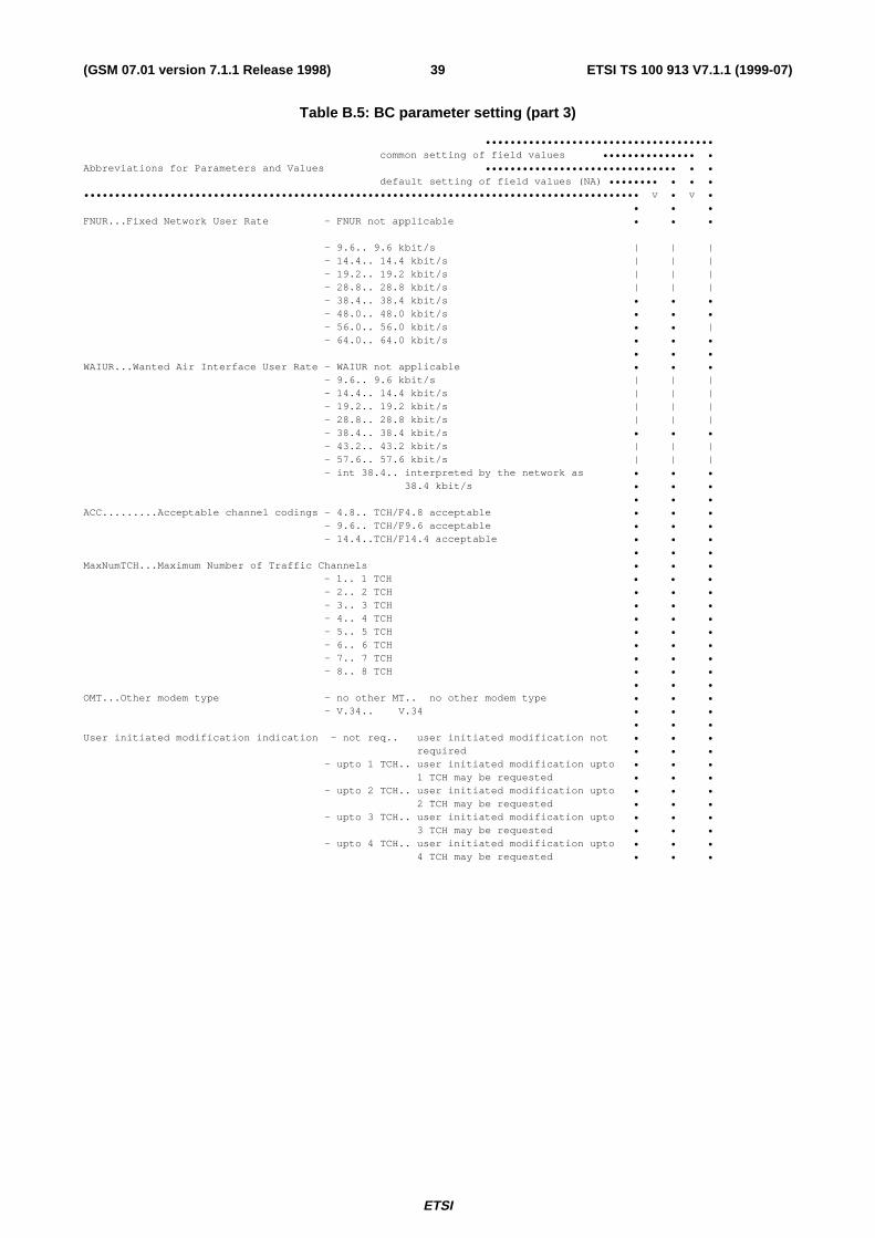
ETSI
ETSI TS 100 913 V7.1.1 (1999-07)39(GSM 07.01 version 7.1.1 Release 1998)
Table B.5: BC parameter setting (part 3)
••••••••••••••••••••••••••••••••••••• common setting of field values ••••••••••••••• •Abbreviations for Parameters and Values ••••••••••••••••••••••••••••••• • • default setting of field values (NA) •••••••• • • ••••••••••••••••••••••••••••••••••••••••••••••••••••••••••••••••••••••••••••••••••••••••••• v • v • • • •FNUR...Fixed Network User Rate - FNUR not applicable • • •
- 9.6.. 9.6 kbit/s | | | - 14.4.. 14.4 kbit/s | | | - 19.2.. 19.2 kbit/s | | | - 28.8.. 28.8 kbit/s | | | - 38.4.. 38.4 kbit/s • • • - 48.0.. 48.0 kbit/s • • • - 56.0.. 56.0 kbit/s • • | - 64.0.. 64.0 kbit/s • • • • • •WAIUR...Wanted Air Interface User Rate - WAIUR not applicable • • • - 9.6.. 9.6 kbit/s | | | - 14.4.. 14.4 kbit/s | | | - 19.2.. 19.2 kbit/s | | | - 28.8.. 28.8 kbit/s | | | - 38.4.. 38.4 kbit/s • • • - 43.2.. 43.2 kbit/s | | | - 57.6.. 57.6 kbit/s | | | - int 38.4.. interpreted by the network as • • • 38.4 kbit/s • • • • • •ACC.........Acceptable channel codings - 4.8.. TCH/F4.8 acceptable • • • - 9.6.. TCH/F9.6 acceptable • • • - 14.4..TCH/F14.4 acceptable • • • • • •MaxNumTCH...Maximum Number of Traffic Channels • • • - 1.. 1 TCH • • • - 2.. 2 TCH • • • - 3.. 3 TCH • • • - 4.. 4 TCH • • • - 5.. 5 TCH • • • - 6.. 6 TCH • • • - 7.. 7 TCH • • • - 8.. 8 TCH • • • • • •OMT...Other modem type - no other MT.. no other modem type • • • - V.34.. V.34 • • • • • •User initiated modification indication - not req.. user initiated modification not • • • required • • • - upto 1 TCH.. user initiated modification upto • • • 1 TCH may be requested • • • - upto 2 TCH.. user initiated modification upto • • • 2 TCH may be requested • • • - upto 3 TCH.. user initiated modification upto • • • 3 TCH may be requested • • • - upto 4 TCH.. user initiated modification upto • • • 4 TCH may be requested • • •

ETSI
ETSI TS 100 913 V7.1.1 (1999-07)40(GSM 07.01 version 7.1.1 Release 1998)
Table B.6: Channel combinations
Single Bearer and Teleservices
MS indication Network selection CTBC CTFR FRdual FR FR or HRdual HR HR or FRAlternate services
MS indication Network selectionBC(1) BC(2) CT(1) CT(2) or CT(1) CT(2)FR FR FR FRFR dual Rate FR FRdual Rate dual Rate FR FR or HR HRdual Rate FR FR FRFollowed-by services
MS indication Network selectionBC(1) BC(2) CT(1) CT(2) or CT(1) CT(2) or CT(1) CT(2)FR FR FR FRFR dual Rate FR FRdual Rate dual Rate FR FR or HR HR or FR HRdual Rate FR FR FR
BC Bearer CapabilityCT Channel Typedual Rate {dual FR | dual HR}
Table B.7: TS61/TS62 Negotiation rules
Mobile Originating Call
Subscription SETUP CALL PROCEEDTS61 TS61 s/f
TS61 f/sTS61 s/f or TS62TS61 f/s or TS62
TS62 TS62TS62 TS61 s/f
TS61 f/sTS62TS62
TS62 TS62Mobile Terminating Call
Subscription SETUP CALL CONFIRMEDTS61 TS61 s/f TS61 s/f or TS61 f/s or TS62
TS61 f/s TS61 s/f or TS61 f/s or TS62TS62 TS62no BC TS61 s/f or TS61 f/s or TS62
TS62 TS62 TS62no BC TS62 (Note1)
s/f = speech then faxf/s = fax then speech
NOTE 1: TS61 is also accepted if the VMSC supports TS61 and does not perform subscription checking on aCALL CONFIRMED message (see GSM 02.01 and GSM 09.07).
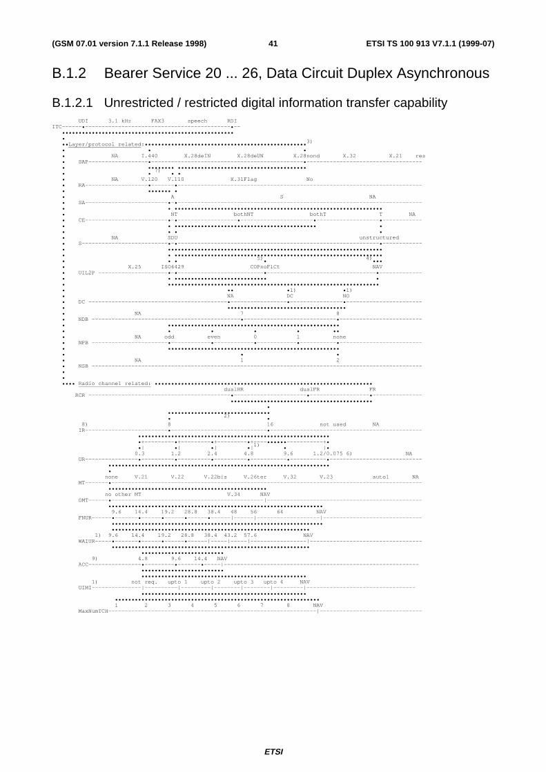
ETSI
ETSI TS 100 913 V7.1.1 (1999-07)41(GSM 07.01 version 7.1.1 Release 1998)
B.1.2 Bearer Service 20 ... 26, Data Circuit Duplex Asynchronous
B.1.2.1 Unrestricted / restricted digital information transfer capability UDI 3.1 kHz FAX3 speech RDIITC------•--------------------------------------------•-- •••••••••••••••••••••••••••••••••••••••••••••••••••• • ••Layer/protocol related:••••••••••••••••••••••••••••••••••••••••••••••••• 3)
• • • • NA I.440 X.28deIN X.28deUN X.28nond X.32 X.21 res • SAP------------------•----------------------------------------------•----------------------------------- • •••••••• ••••••••••••••••••••••••••••••••••••••• • • 7) • • • NA V.120 V.110 X.31Flag No • RA-------------------•-------•-------------------------------------------------------------------------- • ••••••• • • A S NA • SA-------------------------•-•-------------------------------------------------------------------------- • • ••••••••••••••••••••••••••••••••••••••••••••••••••••••••••••••• • NT bothNT bothT T NA • CE-------------------------•-•------------------•----------------------•-------------------•------------ • • ••••••••••••••••••••••••••••••••••••••••••• • • • • • • NA SDU unstructured • S--------------------------•-•-------------------------------------------------------------•------------ • ••••••••••••••••••••••••••••••••••••••••••••••••••••••••••••••••• • • ••••••••••••••••••••••••••••••••••••••••••••••••••••••••••••••• • • • 5) • 4) ••• • X.25 ISO6429 COPnoFlCt NAV • UIL2P ---------------------•-•--------------------------•---------------------------------•------------- • • •••••••••••••••••••••••••••• • • •••••••••••••••••••••••••••••••••••••••••••••••••••••••••••••••• • •• •1) •1) • NA DC NO • DC ------------------------------------------•-----------------•----------------•----------------------- • •••••••••••••••••••••••••••••••••••• • NA 7 8 • NDB ---------------------------------------------•----------------------------•------------------------- • •••••••••••••••••••••••••••••••••••••••••••••••••••• • • • • • •• • NA odd even 0 1 none • NPB -----------------------•------------•------------•------------•-----------•------------------------- • •••••••••••••••••••••••••••••••••••••••••••••••••••• • • • • NA 1 2 • NSB ---------------------------------------------------------------------------------------------------- • • •••• Radio channel related: •••••••••••••••••••••••••••••••••••••••••••••••••••••••••••••••••• dualHR dualFR FR RCR -------------------------------------------•----------------------•------------------•--------------- ••••••••••••••••••••••••••••••••••••••••••• • ••••••••••••••••••••••••••••••• • 2) • 8) 8 16 not used NA IR-------------------------•-----------------------------•---------------------------------------------- •••••••••••••••••••••••••••••••••••••••••••••••••••••••••• •+---------•+---------•+---------•+----••••••-----------+• •| •| •| •| 1) • |• 0.3 1.2 2.4 4.8 9.6 1.2/0.075 6) NA UR----------------•----------•----------•----------•-----------•-----------•---------------------------- ••••••••••••••••••••••••••••••••••••••••••••••••••••••••••••••••••• • none V.21 V.22 V.22bis V.26ter V.32 V.23 auto1 NA MT-------•---------------------------------------------------------------------------------------------- •••••••••••••••••••••••••••••••••••••••••••••••• no other MT V.34 NAV OMT------•----------------------------------------------|----------------------------------------------- ••••••••••••••••••••••••••••••••••••••••••••••••••••••••••••••••• 9.6 14.4 19.2 28.8 38.4 48 56 64 NAV FNUR------•-------•------•------•------•------|------|-------------------|------------------------------ •••••••••••••••••••••••••••••••••••••••••••••••••••••••••••••••• •••••••••••••••••••••••••••••••••••••••••••••••••••••••••••• 1) 9.6 14.4 19.2 28.8 38.4 43.2 57.6 NAV WAIUR-----•-------•------•------•------|-----|-----|-----------------|---------------------------------- •••••••••••••••••••••••••••••••••••••••••••••••••••••••••••• ••••••••••••••••••••••••• 9) 4.8 9.6 14.4 NAV ACC----------------•---------•-------•-----|----------------------------------------------------------- ••••••••••••••••••••••••• •••••••••••••••••••••••••••••••••••••••••••••••••• 1) not req. upto 1 upto 2 upto 3 upto 4 NAV UIMI---------------|----------|---------|--------|--------|---------|--------------------------------- •••••••••••••••••••••••••••••••••••••••••••••••••• •••••••••••••••••••••••••••••••••••••••••••••••••••••••••••••• 1 2 3 4 5 6 7 8 NAV MaxNumTCH---------------------------------------------------------------|-------------------------------

ETSI
ETSI TS 100 913 V7.1.1 (1999-07)42(GSM 07.01 version 7.1.1 Release 1998)
1) for CE:NT or "both";2) for CE:T only or CE:NT and NIRR:6kb/s (not for the SETUP message);3) for MOC only;4) for MTC in the SETUP message or MOC/MTC with "out-band" flow control requested5) for MOC/MTC with no flow control requested;6) MOC only, 75 bit/s in the uplink, 1200 bit/s in the downlink direction;7) the V.120 relevant BC parameters (octet 5b) shall be set according to the LLC (see annex B.2);8) IR and UR are overridden if FNUR, ACC and MaxNumTCH are available.9) ACC may have several values simultaneously (bit map coding).

ETSI
ETSI TS 100 913 V7.1.1 (1999-07)43(GSM 07.01 version 7.1.1 Release 1998)
B.1.2.2 3.1 kHz audio ex-PLMN information transfer capability UDI 3.1 kHz FAX3 speechITC-----------------•------------------------------------ • •••••••••••••••••• • ••Layer/protocol related:•••••••••••••••••••••••••••••••••••••••••••••••• 3)
• • • • NA I.440 X.28deIN X.28deUN X.28nond X.32 X.21 res • SAP------------------•---------------------------------------------•------------------------------------ • ••••••••••••••••••••••••••••••••••••••••••••••• • • • NA V.110 X.31Flag No • RA-----------------------------------------------------------------•------------------------------------ • ••••••••••••••••••••••••••••••••••••••••• • A S NA • SA-------------------------•---------------------------------------------------------------------------- • ••••••••••••••••••••••••••••••••••••••••••••••••••••••••••••••• • • • • • • NT bothNT bothT T NA • CE-------------------------•------------------•----------------------•-------------------•-------------- • ••••••••••••••••••••••••••••••••••••••••••• • • • • • NA SDU unstructured • S---------------------------•------------------------------------------------------------•-------------- • • • • •••••••••••••••••••••••••••••••••••••••••••••••••••••••••••••• • • 5) • 4) •• • X.25 ISO6429 COPnoFlCt NAV • UIL2P ----------------------•-------------------------•----------------------------------•-------------- • ••••••••••••••••••••••••••• • • ••••••••••••••••••••••••••••••••••••••••••••• • •• •1) •1) • NA DC NO • DC ------------------------------------------•-----------------•----------------•----------------------- • •••••••••••••••••••••••••••••••••••• • NA 7 8 • NDB ---------------------------------------------•----------------------------•------------------------- • •••••••••••••••••••••••••••••••••••••••••••••••••••• • • • • • •• • NA odd even 0 1 none • NPB -----------------------•------------•------------•------------•-----------•------------------------- • •••••••••••••••••••••••••••••••••••••••••••••••••••• • • • • NA 1 2 • NSB ---------------------------------------------------------------------------------------------------- • • •••• Radio channel related: •••••••••••••••••••••••••••••••••••••••••••••••••••••••••••••••••• dualHR dualFR FR RCR -------------------------------------------•----------------------•------------------•--------------- ••••••••••••••••••••••••••••••••••••••••••• • ••••••••••••••••••••••••••••••• • 2) • 7) 8 16 not_used NA IR-------------------------•-----------------------------•---------------------------------------------- •••••••••••••••••••••••••••••••••••••••••••••••••••••••••• •+---------•+---------•+---------•+----••••••-----------+• •| •| •| •| 1) • |• 0.3 1.2 2.4 4.8 9.6 1.2/0.075 6) NA UR----------------•|---------•|---------•|---------•|----------•|----------•|--------------------------- •+---------•+---------•+---------•+----------•+----------•+--------------+ • • • ••••••••••••• • | 1)
• • ••••••••••••• •• • | none V.21 V.22 V.22bis V.26ter V.32 V.23 auto1 NA MT----------------|----------|----------|----------|-----------|-----------|---------------|------------ ••••••••••••••••••••••••••••••••••••••••••••••••••••••••••••••••••••••••••••••••••• no other MT V.34 NAV ••••••••••••••••••••••••••••••••••••••••••••••••••••••••• OMT------•---------------------------------------------------------------------------------------------- •••••••••••••••••••••••••••••••••••••••••••••••••••••••••• 9) 9.6 14.4 19.2 28.8 38.4 48 56 64 NAV FNUR------•-------•------•------•---------------------------------|------------------------------------- ••••••••••••••••••••••••••••••••••••••••••••••••••••••••• •••••••••••••••••••••••••••••••••••••••••••••••••••••••••••••••• 1) 9.6 14.4 19.2 28.8 38.4 43.2 NAV WAIUR-----•-------•------•------•------•--------•------------------------|------------------------------ ••••••••••••••••••••••••••••••••••••••••••••••••••••••••••••••••
•••••••••••••••••••••••••
8) 4.8 9.6 14.4 NAV
ACC----------------•---------•-------•-----|----------------------------------------------------
••••••••••••••••••••••••• •••••••••••••••••••••••••••••••••••••••••••••••••• 1) not req. upto 1 upto 2 upto 3 upto 4 NAV UIMI---------------|----------|---------|--------|--------|---------|--------------------------------- •••••••••••••••••••••••••••••••••••••••••••••••••• ••••••••••••••••••••••••••••••••••••••••••••••••••••••••• 1 2 3 4 5 6 7 8 NAV NumTCH-------------------------------------------------------------|------------------------------------

ETSI
ETSI TS 100 913 V7.1.1 (1999-07)44(GSM 07.01 version 7.1.1 Release 1998)
1) for CE:NT or "both";2) for CE:T only or CE:NT and NIRR:6kb/s (not for the SETUP message);3) for MOC only;4) for MTC in the SETUP message or MOC/MTC with "out-band" flow control requested
(not for V.21 and V.23 modem types);5) for MOC/MTC with no flow control requested;6) MOC only, 75 bit/s in the uplink, 1200 bit/s in the downlink direction;7) IR and UR are overridden if FNUR, ACC and MaxNumTCH are available.8) ACC may have several values simultaneously (bit map coding).9) in case of MT = auto1 the value of FNUR has no meaning.
B.1.3 Bearer Service 30 ... 34, Data Circuit Duplex Synchronous
B.1.3.1 Unrestricted digital information transfer capability

ETSI
ETSI TS 100 913 V7.1.1 (1999-07)45(GSM 07.01 version 7.1.1 Release 1998)
B.1.3.1.1 Non-X.32 Cases UDI 3.1 kHz FAX3 speechITC------•---------------------------------------------- ••••••• • ••Layer/protocol related:•••••••••••••••••••••••••••••••••••••••••••••••••••••••••••••••••••••••••••• • • • • NA I.440 X.28deIN X.28deUN X.28nond X.32 X.21 res • SAP------------------•-------------------------------------------------------------------------•-------- • • • • ••••••••••••••••••••••••••••••••••••••••••••••••••••••••••••••••••••••••••• • •• • NA V.110 X.31Flag No • RA-------------------------•---------------------------------------------------------------------------- • • • •••••••••••••••••••••••••••••••••• • A S NA • SA----------------------------------------------------------•------------------------------------------- • •••••••••••••••••••••••••••••• • • • NT bothNT bothT T NA • CE---------------------------------------------------------------------------------------•-------------- • • • NA SDU unstructured • S----------------------------------------------------------------------------------------•-------------- • • • • • • • X.25 ISO6429 COPnoFlCt NAV • UIL2P -----------------------------------------------------------------------------------•-------------- • ••••••••••••••••••••••••••••••••••••••••••••••••••••••••••••••••••••••••• • NA 7 8 • NDB -------------•-------------------------------------------------------------------------------------- • • • • • NA odd even 0 1 none • NPB -------------•-------------------------------------------------------------------------------------- • • • • • NA 1 2 • NSB ----------------------------------------------------------------------------------------------------- • • •••• Radio channel related: •••••••••••••••••••••••••••••••••••••••••••••••••••••••••••••••••• dualHR dualFR FR RCR -------------------------------------------•----------------------•------------------•--------------- ••••••••••••••••••••••••••••••••••••••••••• • ••••••••••••••••••••••••••••••• 1) 8 16 not_used NA IR-------------------------•-----------------------------•---------------------------------------------- ••••••••••••••••••••••••• • • • • • • • • •••••• 0.3 1.2 2.4 4.8 9.6 1.2/0.075 NA UR---------------------------•----------•----------•-----------•---------------------------------------- ••••••••••••••••••••••••••••••••••••••••••••••••••••••• • none V.21 V.22 V.22bis V.26ter V.32 V.23 auto1 NA MT-------•---------------------------------------------------------------------------------------------- •••••••••••••••••••••••••••••••••••••••••••••• no other MT V.34 NAV OMT------•--------------------------------------------|------------------------------------------------- ••••••••••••••••••••••••••••••••••••••••••••••••••••••••••• 9.6 14.4 19.2 28.8 38.4 48 56 64 NAV FNUR------•-------•------•------•------•-----•------•--------------•------------------------------------ •••••••••••••••••••••••••••••••••••••••••••••••••••••••••• •••••••••••••••••••••••••••••••••••••••• 9.6 14.4 19.2 28.8 38.4 NAV WAIUR--------------------------------------------------------------|------------------------------------ ••••••••••••••••••••••••••••••••••••••••
•••••••••••••••••••••••••
2) 4.8 9.6 14.4 NAV
ACC----------------•---------•-------•-----|----------------------------------------------------
••••••••••••••••••••••••• •••••••••••••••••••••••••••••••••••••• not req. upto 1 upto 2 upto 3 upto 4 NAV UIMI----------------------------------------------------------------|--------------------------------- ••••••••••••••••••••••••••••••• •••••••••••••••••••••••••••••••••••••••••••••••••••••••••• 1 2 3 4 5 6 7 8 NAV NumTCH--------------------------------------------------------------|-----------------------------------
1) IR and UR are overridden if FNUR, ACC and MaxNumTCH are available2) ACC may have several values simultaneously (bit map coding).

ETSI
ETSI TS 100 913 V7.1.1 (1999-07)46(GSM 07.01 version 7.1.1 Release 1998)
B.1.3.1.2 X.32 Case (Packet Service) UDI 3.1 kHz FAX3 speech RDIITC:-----•--------------------------------------------•-- • • •••••••••••••••••••••••••••••••••••••••••••••••••••• • ••Layer/protocol related:••••••••••••••••••••••••••••••••••••••••••••••••••••••••••••••• • • • NA I.440 X.28deIN X.28deUN X.28nond X.32 X.21 res • SAP-------------------------------------------------------------------------------•--------------------- • • • ••••••••••••••••••••••••••••••••••••• • • • 2)3)
• NA V.110 X.31Flag V.120 No • RA--------------------------------------------•-------------•-------------------------------------------- • ••••••••••••••• • • • A S NA • SA----------------------------------------------------------•------------------------------------------- • •••••••••••••••••••••••••••••••••• • • • NT bothNT bothT T NA • CE-------------------------•---------------------------------------------------------------------------- • • • • • NA SDU unstructured • S--------------------------•---------------------------------------------------------------------------- • • • ••••••••••• • • • 2) • x.25 X.75 ISO6429 COPnoFlCt NAV • UIL2P -----------•-----•-------------------------------------------------------------------------------- • ••••••• • NA 7 8 • NDB -------------•-------------------------------------------------------------------------------------- • • • • • NA odd even 0 1 none • NPB -------------•-------------------------------------------------------------------------------------- • • • • • NA 1 2 • NSB ---------------------------------------------------------------------------------------------------- • • •••• Radio channel related: •••••••••••••••••••••••••••••••••••••••••••••••••••••••••••••••••• dualHR dualFR FR RCR -------------------------------------------•----------------------•------------------•--------------- ••••••••••••••••••••••••••••••••••••••••••• ••••••••••••••••••••••••••••••• 8 1) 16 not_used NA IR-------------------------•-----------------------------•---------------------------------------------- ••••••••••••••••••••••••• • • • • ••••••••••••••••••••••• 0.3 1.2 2.4 4.8 9.6 1.2/0.075 NA UR--------------------------------------•----------•-----------•----------- ---------------------------- ••••••••••••••••••••••••••••••••••••••••••••••••••••••• • none V.21 V.22 V.22bis V.26ter V.32 V.23 auto1 NA MT-------•---------------------------------------------------------------------------------------------- ••••••••••••••••••••••••••••••••••••••••••••••••••••• no other MT V.17 V.34 NAV OMT------•---------------------------------------------------|------------------------------------------
••••••••••••••••••••••••••••••••••••••••••••••••••••••••••
9.6 14.4 19.2 28.8 38.4 48 56 64 NAV
FNUR------•-------•------•------•------•------•-----•-------------|-------------------------------------
•••••••••••••••••••••••••••••••••••••••••••••••••••••••••
••••••••••••••••••••••••••••••••••••••••••••••••••
9.6 14.4 19.2 28.8 38.4 43.2 57 NAV
WAIUR-----•-------•------•------•------•------•------•-----|-------------------------------------
••••••••••••••••••••••••••••••••••••••••••••••••••
••••••••••••••••••••••••••••••••••••••••••••••••••
not req. upto 1 upto 2 upto 3 upto 4 NAV
UIMI---------------|----------|---------|--------|--------|---------|---------------------------------
••••••••••••••••••••••••••••••••••••••••••••••••••
•••••••••••••••••••••••••
4) 4.8 9.6 14.4 NAV
ACC----------------•---------•-------•-----|----------------------------------------------------
••••••••••••••••••••••••• ••••••••••••••••••••••••••••••••••••••••••••••••••••••••••• 1 2 3 4 5 6 7 8 NAV NumTCH--------------------------------------------------------------------------------------------------

ETSI
ETSI TS 100 913 V7.1.1 (1999-07)47(GSM 07.01 version 7.1.1 Release 1998)
1) for NIRR:6kb/s (not for the SETUP message)
2) not for packet handler access
3) the V.120 relevant BC parameters (octet 5b) shall be set according to the LLC (see annex B.2)
4) ACC may have several values simultaneously (bit map coding).

ETSI
ETSI TS 100 913 V7.1.1 (1999-07)48(GSM 07.01 version 7.1.1 Release 1998)
B.1.3.1.3 48kbit/s and 56 kbit/s transparent CaseUDI 3.1 kHz FAX3 speechITC------•---------------------------------------------- ••••••• • ••Layer/protocol related:•••••••••••••••••••••••••••••••••••••••••••••••••••••••••••••••••••••••••••• • • • • NA I.440 X.28deIN X.28deUN X.28nond X.32 X.21 res • SAP------------------•-------------------------------------------------------------------------•-------- • • • • ••••••••••••••••••••••••••••••••••••••••••••••••••••••••••••••••••••••••••• • •• • NA V.110 X.31Flag No • RA-------------------------•---------------------------------------------------------------------------- • • • •••••••••••••••••••••••••••••••••• • A S NA • SA----------------------------------------------------------•------------------------------------------- • •••••••••••••••••••••••••••••• • • • NT bothNT bothT T NA • CE---------------------------------------------------------------------------------------•-------------- • • • NA SDU unstructured • S----------------------------------------------------------------------------------------•-------------- • • • • • • • X.25 ISO6429 COPnoFlCt NAV • UIL2P -----------------------------------------------------------------------------------•-------------- • ••••••••••••••••••••••••••••••••••••••••••••••••••••••••••••••••••••••••• • NA 7 8 • NDB -------------•-------------------------------------------------------------------------------------- • • • • • NA odd even 0 1 none • NPB -------------•-------------------------------------------------------------------------------------- • • • • • NA 1 2 • NSB ----------------------------------------------------------------------------------------------------- • • •••• Radio channel related: •••••••••••••••••••••••••••••••••••••••••••••••••••••••••••••••••• • dualHR dualFR FR RCR -------------------------------------------------------------------------------------•--------------- •••••••••••••••••••••••••••••••• • 1) 8 16 not_used NA IR-------------------------------------------------------•---------------------------------------------- • ••••••• 1) 0.3 1.2 2.4 4.8 9.6 1.2/0.075 NA UR-------------------------------------------------------------•---------------------------------------- • ••••••••••••••••••••••••••••••••••••••••••••••••••••••• none V.21 V.22 V.22bis V.26ter V.32 V.23 auto1 NA MT-------•---------------------------------------------------------------------------------------------- • no other MT V.34 NAV OMT------•---------------------------------------------------------------------------------------------- ••••••••••••••••••••••••••••••••••••••••••• 9.6 14.4 19.2 28.8 38.4 48 56 64 FNUR-----------------------------------------•-----•---------------------------------------------------- ••••••••••••••••••••••• 9.6 14.4 19.2 28.8 38.4 NAV WAIUR--------------------------------------------------------------|------------------------------------ ••••••••••••••••••••••••
•
2) 4.8 9.6 14.4 NAV
ACC-----------------------------------------•-----------------------------------------------------------
•
•••••••••••••••••••••••••
not req. upto 1 upto 2 upto 3 upto 4 NAV
UIMI----------------------------------------------------------------|---------------------------------
••••••••••••••••••••••••••••
•
3) 1 2 3 4 5 6 7 8
NumTCH--------------------------------------------------------------------------------------------------
1) IR and UR are overridden by FNUR, ACC and MaxNumTCH are available
2) ACC may have several values simultaneously (bit map coding).
3) For a 4 channel operation see table B.1.3.1.1.
NOTE: The parameters FNUR, OMT, ACC and MaxNumTCH are mandatory for this service.

ETSI
ETSI TS 100 913 V7.1.1 (1999-07)49(GSM 07.01 version 7.1.1 Release 1998)
B.1.3.1.4 64kbit/s bit transparent Case UDI 3.1 kHz FAX3 speechITC------•---------------------------------------------- ••••••• • ••Layer/protocol related:•••••••••••••••••••••••••••••••••••••••••••••••••••••••••••••••••••••••••••• • • • • NA I.440 X.28deIN X.28deUN X.28nond X.32 X.21 res • SAP------------------•-------------------------------------------------------------------------•-------- • • • • ••••••••••••••••••••••••••••••••••••••••••••••••••••••••••••••••••••••••••••••••••••• • • • NA V.110 X.31Flag No • RA---------•-------------------------------------------------------------------------------------------- • • • ••••••••••••••••••••••••••••••••••••••••••••••••••••••••••••••••••••••••••••• • A S NA • SA-------------------------------------------------------------------------------------•---------------- • ••• • • • NT bothNT bothT T NA • CE---------------------------------------------------------------------------------------•-------------- • • • NA SDU unstructured • S----------------------------------------------------------------------------------------•-------------- • • • • • • • X.25 ISO6429 COPnoFlCt NAV • UIL2P -----------------------------------------------------------------------------------•-------------- • ••••••••••••••••••••••••••••••••••••••••••••••••••••••••••••••••••••••••• • NA 7 8 • NDB -------------•-------------------------------------------------------------------------------------- • • • • • NA odd even 0 1 none • NPB -------------•-------------------------------------------------------------------------------------- • • • • • NA 1 2 • NSB ----------------------------------------------------------------------------------------------------- • • •••• Radio channel related: •••••••••••••••••••••••••••••••••••••••••••••••••••••••••••••••••• • dualHR dualFR FR RCR -------------------------------------------------------------------------------------•--------------- •••••••••••••••••••••••••••••••• • • • 1) 8 16 not_used NA IR-------------------------------------------------------•---------------------------------------------- • • ••••••• 1) 0.3 1.2 2.4 4.8 9.6 1.2/0.075 NA UR-------------------------------------------------------------•---------------------------------------- • ••••••••••••••••••••••••••••••••••••••••••••••••••••••• none V.21 V.22 V.22bis V.26ter V.32 V.23 auto1 NA MT-------•---------------------------------------------------------------------------------------------- • no other MT V.34 OMT------•---------------------------------------------------------------------------------------------- ••••••••••••••••••••••••••••••••••••••••••••••••••• 9.6 14.4 19.2 28.8 38.4 48 56 64 FNUR-------------------------------------------------------|-------------------------------------------- ••••••••• • 9.6 14.4 19.2 28.8 38.4 NAV WAIUR--------------------------------------------------------------|------------------------------------ ••••••••••••••••••••••• •
••••••••••
2) 4.8 9.6 14.4
ACC-------------------------------------------•-------|-------------------------------------------------
••••••••• ••••••••••••••••••••• not req. upto 1 upto 2 upto 3 upto 4 NAV UIMI----------------------------------------------------------------|--------------------------------- •••••••••••••••••••••••••••• • • 1 2 3 4 5 6 7 8 NumTCH--------------------------------------------------------------------------------------------------
1) IR and UR are overridden by FNUR, ACC and MaxNumTCH are available
2) ACC may have several values simultaneously (bit map coding).
NOTE: The parameters FNUR, OMT, ACC and MaxNumTCH are mandatory for this service.

ETSI
ETSI TS 100 913 V7.1.1 (1999-07)50(GSM 07.01 version 7.1.1 Release 1998)
B.1.3.2 3.1 kHz audio ex-PLMN information transfer capability
B.1.3.2.1 Non-X.32 Cases UDI 3.1 kHz FAX3 speechITC:----------------•----------------------------------- • •••••••••••••••••• • ••Layer/protocol related:•• • • • NA I.440 X.28deIN X.28deUN X.28nond X.32 X.21 res • SAP------------------•---------------------------------------------------------------------------------- • • • ••••••••••••••••••••••••••••••••••••••••••••••• • • • NA V.110 X.31Flag No • RA-----------------------------------------------------------------•------------------------------------ • •••••••• • • • A S NA • SA----------------------------------------------------------•------------------------------------------- • •••••••••••••••••••••••••••••• • • • NT bothNT bothT T NA • CE---------------------------------------------------------------------------------------•-------------- • • • • • NA SDU unstructured • S----------------------------------------------------------------------------------------•-------------- • • • • • • • X.25 ISO6429 COPnoFlCt NAV • UIL2P -----------------------------------------------------------------------------------•-------------- • ••••••••••••••••••••••••••••••••••••••••••••••••••••••••••••••••••••••••• • NA 7 8 • NDB -------------•-------------------------------------------------------------------------------------- • • • • • NA odd even 0 1 none • NPB -------------•-------------------------------------------------------------------------------------- • • • • • NA 1 2 • NSB ----------------------------------------------------------------------------------------------------- • •••• Radio channel related: •••••••••••••••••••••••••••••••••••••••••••••••••••••••••••••••••• dualHR dualFR FR RCR -------------------------------------------•----------------------•------------------•--------------- ••••••••••••••••••••••••••••••••••••••••••• ••••••••••••••••••••••••••••••• 8 16 not_used NA IR-------------------------•-----------------------------•---------------------------------------------- ••••••••••••••••••••••••• • • • • • • • • •••••• 0.3 1.2 2.4 4.8 9.6 1.2/0.075 NA UR---------------------------•----------•----------•-----------•----------- ---------------------------- • • ••••••••••••• • •••••••••••••• •• none V.21 V.22 V.22bis V.26ter V.32 V.23 auto1 NA MT---------------------------•----------•------------•---------•---------------------------------------- ••••••••••••••••••••••••••••••••••••••••••••••••••••••• no other MT V.34 NAV •••••••••••••••••••••••••••••••••••••••••••••• OMT------•---------------------------------------------------------------------------------------------- ••••••••••••••••••••••••••••••••••••••••••••••••••••••••• 9.6 14.4 19.2 28.8 38.4 48 56 64 NAV FNUR------•-------•------•------•--------------------------------|-------------------------------------- •••••••••••••••••••••••••••••••••••••••••••••••••••••••• •••••••••••••••••••••••••••••••••••••• 9.6 14.4 19.2 28.8 38.4 NAV WAIUR------------------------------------------------------------|-------------------------------------- ••••••••••••••••••••••••••••••••••••••
•••••••••••••••••••••••••
1) 4.8 9.6 14.4 NAV
ACC----------------•---------•-------•-----|------------------------------------------------------------
••••••••••••••••••••••••• •••••••••••••••••••••••••••••• not req. upto 1 upto 2 upto 3 upto 4 NAV UIMI----------------------------------------------------------------|--------------------------------- ••••••••••••••••••••••••••••••• ••••••••••••••••••••••••••••••••••••••••••••••••••••••••••• 1 2 3 4 5 6 7 8 NAV NumTCH---------------------------------------------------------------|----------------------------------
1) ACC may have several values simultaneously (bit map coding).

ETSI
ETSI TS 100 913 V7.1.1 (1999-07)51(GSM 07.01 version 7.1.1 Release 1998)
B.1.3.2.2 X.32 Case (Packet Service)
UDI 3.1 kHz FAX3 speechITC:---------------•------------------------------------ • ••••••••••••••••• ••Layer/protocol related:••••••••••••••••••••••••••••••••••••••••••••••••••••••••••••••• • • • NA I.440 X.28deIN X.28deUN X.28nond X.32 X.21 res • SAP-------------------------------------------------------------------------------•--------------------- • •••••••••••••••• • • • NA V.110 X.31Flag No • RA-----------------------------------------------------------------•------------------------------------ • •••••••• • A S NA • SA----------------------------------------------------------•------------------------------------------- • ••••••••••••••••••••••••••••••••••••••••••••••••••••••••••••••• • NT bothNT bothT T NA • CE-------------------------•------------------•----------------------•-------------------•-------------- • ••••••••••••••••••••••••••••••••••••••••••• • • •• • • NA SDU unstructured • S--------------------------•-------------------------------------------------------------•-------------- • ••••••••••• • • • • • x.25 ISO6429 COPnoFlCT NAV • UIL2P -----------•-----------------------------------------------------------------------•-------------- • ••••••••••••••••••••••••••••••••••••••••••••••••••••••••••••••••••••••••• • NA 7 8 • NDB -------------•-------------------------------------------------------------------------------------- • • • NA odd even 0 1 none • NPB -------------•-------------------------------------------------------------------------------------- • • • NA 1 2 • NSB ----------------------------------------------------------------------------------------------------- • • •••• Radio channel related: •••••••••••••••••••••••••••••••••••••••••••••••••••••••••••••••••• dualHR dualFR FR RCR -------------------------------------------•----------------------•------------------•--------------- ••••••••••••••••••••••••••••••••••••••••••• ••••••••••••••••••••••••••••••• • 2) • 8 16 not_used NA IR-------------------------•-----------------------------•---------------------------------------------- ••••••••••••••••••••••••• • •+---------•+----• •• •• 1) •••••• 0.3 1.2 2.4 4.8 9.6 1.2/0.075 NA UR--------------------------------------•----------•-----------•----------- ---------------------------- • ••••••••••••• •••••••••••••• •• none V.21 V.22 V.22bis V.26ter V.32 V.23 auto1 NA MT---------------------------•----------•------------•---------•---------------------------------------- ••••••••••••••••••••••••••••••••••••••••••••••••••••••• no other MT V.34 NAV •••••••••••••••••••••••••••••••••••••••••••••• OMT------•---------------------------------------------------------------------------------------------- ••••••••••••••••••••••••••••••••••••••••••••••••••••••••• 9.6 14.4 19.2 28.8 38.4 NAV FNUR------•-------•------•------•--------------------------------|-------------------------------------- •••••••••••••••••••••••••••••••••••••••••••••••••••••••• •••••••••••••••••••••••••••••••••••••••••••••••••••••••••••••••• 1) 9.6 14.4 19.2 28.8 38.4 NAV WAIUR-----•-------•------•------•----------------------------------------|------------------------------ •••••••••••••••••••••••••••••••••••••••••••••••••••••••••••••••• •••••••••••••••••••••••••••••••••••• 3) 4.8 9.6 14.4 NAV ACC----------------•-----------•-------------•--------|------------------------------------------------- •••••••••••••••••••••••••••••••••••• ••••••••••• • •••••••• • •••••••••• • •••••••• • ••••••••• 1) not req. upto 1 upto 2 upto 3 upto 4 NA UIMI--------------•----------•--------•----------•--------•---------•--------------------------------- ••••••••••• • •••••••• • •••••••••• • •••••••• • ••••••••• ••••••••••••••••••••••••••••••••••••••••••••••••••••••••••• 1 2 3 4 5 6 7 8 NAV NumTCH---------------------------------------------------------------|----------------------------------
1) for CE:NT or "both"
2) for CE:T or CE:NT and NIRR:6kb/s (not for the SETUP message)
3) ACC may have several values simultaneously (bit map coding).

ETSI
ETSI TS 100 913 V7.1.1 (1999-07)52(GSM 07.01 version 7.1.1 Release 1998)
B.1.4 Bearer Service 40 ... 46, PAD Access Asynchronous UDI 3.1 kHz FAX3 speechITC------•---------------------------------------------- ••••••• • ••Layer/protocol related:••••••••••••••••••••••••••••••••• • • • NA I.440 X.28deIN X.28deUN X.28nond X.32 X.21 res • SAP-------------------------------- ----------------•--------------------------------------------------- • •••••••••••••••••••••••••• • • • NA V.110 X.31Flag No • RA-------------------------•---------------------------------------------------------------------------- • • • A S NA • SA-------------------------•---------------------------------------------------------------------------- • ••••••••••••••••••••••••••••••••••••••••••••••••••••••••••••••• • NT bothNT bothT T NA • CE-------------------------•------------------•----------------------•-------------------•-------------- • ••••••••••••••••••••••••••••••••••••••••••• • • •• • • NA SDU unstructured • S---------------------------•------------------------------------------------------------•-------------- • •••••••••••••••••••••••••••••••••••••••••••••••••••••••••••••• • • 4)• 3)•• • x.25 ISO6429 COPnoFlCT NAV • UIL2P ----------------------•-----------------------------•------------------------------•-------------- • ••••••••••••••••••••••••••••••• • • ••••••••••••••••••••••••••••••••••••••••••••• • •• •1) •1) • NA DC NO • DC ------------------------------------------•-----------------•----------------•----------------------- • •••••••••••••••••••••••••••••••••••• • NA 7 8 • NDB ---------------------------------------------•----------------------------•------------------------- • •••••••••••••••••••••••••••••••••••••••• • • • • • • • • NA odd even 0 1 none • NPB -----------------------•------------•------------•------------•-----------•------------------------- • •••••••••••••••••••••••••••••••••••••••••••••••••••• • • • • NA 1 2 • NSB ---------------------------------------------------------------------------------------------------- • • •••• Radio channel related: •••••••••••••••••••••••••••••••••••••••••••••••••••••••••••••••••• • • • dualHR dualFR FR RCR -------------------------------------------•----------------------•------------------•--------------- ••••••••••••••••••••••••••••••••••••••••••• • ••••••••••••••••••••••••••••••• | 2) • 8 16 not_used NA IR-------------------------•-----------------------------•---------------------------------------------- •••••••••••••••••••••••••••••••••••••••••••••••••••••••••• •+---------•+---------•+---------•+----••••••-----------+• •| •| •| •| 1) • |• 0.3 1.2 2.4 4.8 9.6 1.2/0.075 5) NA UR----------------•----------•----------•----------•-----------•-----------•---------------------------- • • • • • • ••••••••••••••••••••••••••••••••••••••••••••••••••••••••••••••••••• • none V.21 V.22 V.22bis V.26ter V.32 V.23 auto1 NA MT-------•---------------------------------------------------------------------------------------------- •••••••••••••••••••••••••••••••••••••••••••••••• no other MT V.34 NAV OMT------•----------------------------------------------|-----------------------------------------------
••••••••••••••••••••••••••••••••••••••••••••••••••••••••••••
9.6 14.4 19.2 28.8 38.4 48 56 64 NAV
FNUR------•-------•------•------•------•------•-----•---------------|-----------------------------------
•••••••••••••••••••••••••••••••••••••••••••••••••••••••••••
••••••••••••••••••••••••••••••••••••••••••••••••••••
1) 9.6 14.4 19.2 28.8 38.4 43.2 57.6 NAV
WAIUR-----•-------•------•------•------•------•------•-------|-----------------------------------
••••••••••••••••••••••••••••••••••••••••••••••••••••
•••••••••••••••••••••••••
6) 4.8 9.6 14.4 NAV
ACC----------------•---------•-------•-----|----------------------------------------------------
••••••••••••••••••••••••• •••••••••••••••••••••••••••••••••••••••••••••••••• 1) not req. upto 1 upto 2 upto 3 upto 4 NAV UIMI---------------|----------|---------|--------|--------|---------|--------------------------------- •••••••••••••••••••••••••••••••••••••••••••••••••• •••••••••••••••••••••••••••••••••••••••••••••••••••••••••••••• 1 2 3 4 5 6 7 8 NAV NumTCH------------------------------------------------------------------|-------------------------------

ETSI
ETSI TS 100 913 V7.1.1 (1999-07)53(GSM 07.01 version 7.1.1 Release 1998)
1) for CE:NT or "both";2) for CE:T only or CE:NT and NIRR:6kb/s (not for the SETUP message);3) for MOC with "outband" flow control requested;4) for MOC with no flow control requested;5) MOC only, 75 bit/s in the uplink, 1200 bit/s in the downlink direction.6) ACC may have several values simultaneously (bit map coding).

ETSI
ETSI TS 100 913 V7.1.1 (1999-07)54(GSM 07.01 version 7.1.1 Release 1998)
B.1.5 Bearer Service 50 ... 53 ,Data Packet Duplex Synchronous,Unrestricted digital information transfer capability
UDI 3.1 kHz FAX3 speechITC:-----•---------------------------------------------- ••••••• • ••Layer/protocol related:••••••••••••••••••••••••••••••••••••••••••••••••••••••••••••••• • • • NA I.440 X.28deIN X.28deUN X.28nond X.32 X.21 res • SAP-------------------------------------------------------------------------------•--------------------- • ••••••••••••••••••••••••••••••••••••• • NA V.110 X.31Flag No • RA--------------------------------------------•--------------------------------------------------------- • ••••••••••••••• • A S NA • SA----------------------------------------------------------•------------------------------------------- • •••••••••••••••••••••••••••••••••• • NT bothNT bothT T NA • CE-------------------------•---------------------------------------------------------------------------- • • • NA SDU unstructured • S--------------------------•---------------------------------------------------------------------------- • ••••••••••• • • • x.25 ISO6429 COPnoFlCt NAV • UIL2P -----------•-------------------------------------------------------------------------------------- • • • NA 7 8 • NDB -------------•-------------------------------------------------------------------------------------- • • • NA odd even 0 1 none • NPB -------------•-------------------------------------------------------------------------------------- • • • NA 1 2 • NSB ----------------------------------------------------------------------------------------------------- • • •••• Radio channel related: •••••••••••••••••••••••••••••••••••••••••••••••••••••••••••••••••• dualHR dualFR FR RCR -------------------------------------------•----------------------•------------------•--------------- ••••••••••••••••••••••••••••••••••••••••••• ••••••••••••••••••••••••••••••• • 1) • 8 16 not_used NA IR-------------------------•-----------------------------•---------------------------------------------- ••••••••••••••••••••••••• • ••••••••••••+••••• •• •• •••••• 0.3 1.2 2.4 4.8 9.6 1.2/0.075 NA UR--------------------------------------•----------•-----------•----------- ---------------------------- ••••••••••••••••••••••••••••••••••••••••••••••••••••••• • none V.21 V.22 V.22bis V.26ter V.32 V.23 auto1 NA MT-------•---------------------------------------------------------------------------------------------- ••••••••••••••••••••••••••••••••••••••••••••••••• no other MT V.34 NAV NA OMT------•-----------------------------------------------|----------------------------------------------
•••••••••••••••••••••••••••••••••••••••••••••••••••
9.6 14.4 19.2 28.8 38.4 48 56 NAV NA
FNUR------•-------•------•------•------•------•-----•------|--------------------------------------------
••••••••••••••••••••••••••••••••••••••••••••••••••
•••••••••••••••••••••••••••••••••••••••••••••••••••••••••
9.6 14.4 19.2 28.8 38.4 43.2 57.6 NAV
WAIUR-----•-------•------•------•------•------•------•------------|------------------------------
•••••••••••••••••••••••••••••••••••••••••••••••••••••••••
•••••••••••••••••••••••••••
2) 4.8 9.6 14.4 NAV NA
ACC----------------•---------•-------•--------•-------------------------------------------------
••••••••••••••••••••••••••••
•••••••••••••••••••••••••••••••••••••••••••••••••• not req. upto 1 upto 2 upto 3 upto 4 NAV NA UIMI---------------|----------|---------|--------|--------|---------|----------------------------------- •••••••••••••••••••••••••••••••••••••••••••••••••• •••••••••••••••••••••••••••••••••••••••••••••••••••••••••••• 1 2 3 4 5 6 7 8 NAV NA NumTCH----------------------------------------------------------------|---------------------------------
1) for NIRR:6kb/s (not for the SETUP message)2) ACC may have several values simultaneously (bit map coding).

ETSI
ETSI TS 100 913 V7.1.1 (1999-07)55(GSM 07.01 version 7.1.1 Release 1998)
B.1.6 Bearer Service 61, Alternate Speech/DataThe information element of the "repeat indicator" is set to the value "circular for successive selection (alternate)".
B.1.6.1 Bearer Service 61,Speech UDI 3.1 kHz FAX3 speechITC-----------------------------------------•----------- •••••••••••••••••••••••••••••••••••••••••• ••Layer/protocol related:••••••••••••••••••••••••••••••••••••••••••••••••••••••••••••••••••••••••••••••••••• • • • NA I.440 X.28deIN X.28deUN X.28nond X.32 X.21 NAV • SAP---------------------------------------------------------------------------------------------------•- • • • • • NA V.110 X.31Flag No NAV • RA----------------------------------------------------------------------------------------------------•- • • • A S NA NAV • SA----------------------------------------------------------------------------------------------------•- • • • • • NT bothNT bothT T NA NAV • CE ---------------------------------------------------------------------------------------------------•- • • • • • NA NAV • S-----------------------------------------------------------------------------------------------------•- • • • ••••••••••••• • X.25 ISO6429 COPnoFlCt NAV • UIL2P ------------------------------------------------------------------------------------•------------- • ••••••••••••• • • • NA 7 8 NAV • NDB --------------------------------------------------------------------------------------------------•- • • • • • NA odd even none 0 1 NAV • NPB --------------------------------------------------------------------------------------------------•- • • • • • NA 1 2 NAV • NSB ---------------------------------------------------------------------------------------------------- • • • •••• Radio channel related: ••••••••••••••••••••••••••••••••••••••••••••••••••••••••••••••••• • • • dualHR dualFR FR RCR ------------------------------------------•----------------------•------------------•--------------- •••••••••••••••••••••••••••••••••••••••••••••••••••••••••• • 8 16 not used NA NAV IR----------------------------------------------------------------------------------------------------•- • 0.3 1.2 2.4 4.8 9.6 1.2/0.075 NA NAV UR----------------------------------------------------------------------------------------------------•- • • none V.21 V.22 V.22bis V.26ter V.32 V.23 auto1 NA NAV MT----------------------------------------------------------------------------------------------------|- • no other MT V.17 V.34 NAV OMT---------------------------------------------------------------------------------------------------•- • 9.6 14.4 19.2 28.8 38.4 48 56 64 NAV FNUR--------------------------------------------------------------------------------------------------•- • 9.6 14.4 19.2 28.8 38.4 NAV WAIUR-------------------------------------------------------------------------------------------------|- • 4.8 9.6 14.4 NAV ACC---------------------------------------------------------------------------------------------------•- • not req. upto 1 upto 2 upto 3 upto 4 NAV UIMI--------------------------------------------------------------------------------------------------|- • 1 2 3 4 5 6 7 8 NAV NumTCH--------------------------------------------------------------------------------------------------

ETSI
ETSI TS 100 913 V7.1.1 (1999-07)56(GSM 07.01 version 7.1.1 Release 1998)
B.1.6.2 Bearer Service 61, 3.1 kHz audio ex-PLMN information transfercapability
B.1.6.2.1 Asynchronous UDI 3.1 kHz FAX3 speechITC-----------------•------------------------------------ • •••••••••••••••••• • ••Layer/protocol related:•• • • • NA I.440 X.28deIN X.28deUN X.28nond X.32 X.21 res • SAP------------------•---------------------------------------------------------------------------------- • ••••••••••••••••••••••••••••••••••••••••••••••• • • • NA V.110 X.31Flag No • RA-----------------------------------------------------------------•------------------------------------ • ••••••••••••••••••••••••••••••••••••••••• • A S NA • SA-------------------------•---------------------------------------------------------------------------- • ••••••••••••••••••••••••••••••••••••••••••••••••••••••••••••••• • • • • • • NT bothNT bothT T NA • CE-------------------------•------------------•----------------------•-------------------•-------------- • ••••••••••••••••••••••••••••••••••••••••••• • • • • • NA SDU unstructured • S---------------------------•------------------------------------------------------------•-------------- • •••••••••••••••••••••••••••••••••••••••••••••••••••••••••••••• • • 5)• 4)•• • X.25 ISO6429 COPnoFlCt NAV • UIL2P ----------------------•--------------------------•---------------------------------•-------------- • •••••••••••••••••••••••••••• • • ••••••••••••••••••••••••••••••••••••••••••••• • •• •1) •1) • NA DC NO • DC ------------------------------------------•-----------------•----------------•----------------------- • •••••••••••••••••••••••••••••••••••• • NA 7 8 • NDB ---------------------------------------------•----------------------------•------------------------- • •••••••••••••••••••••••••••••••••••••••••••••••••••• • NA odd even 0 1 none • NPB -----------------------•------------•------------•------------•-----------•------------------------- • •••••••••••••••••••••••••••••••••••••••••••••••••••• • • • • NA 1 2 • NSB ---------------------------------------------------------------------------------------------------- • • •••• Radio channel related: •••••••••••••••••••••••••••••••••••••••••••••••••••••••••••••••••• dualHR dualFR FR RCR -------------------------------------------•----------------------•------------------•--------------- ••••••••••••••••••••••••••••••••••••••••••• ••••••••••••••••••••••••••••••• • 2) • 8 16 not_used NA IR-------------------------•-----------------------------•---------------------------------------------- •••••••••••••••••••••••••••••••••••••••••••••••••••••••••• •+---------•+---------•+---------•+----••••••-----------+• •| •| •| •| 1) • |• 0.3 1.2 2.4 4.8 9.6 1.2/0.075 6) NA UR----------------•|---------•|---------•|---------•|----------•|----------•|--------------------------- •+---------•+---------•+---------•+----------•+----------•+--------------+ • • • ••••••••••••• • | 1) • • ••••••••••••• •• • | none V.21 V.22 V.22bis V.26ter V.32 V.23 auto1 NA MT----------------•----------•----------•----------•-----------•-----------•---------------•------------ ••••••••••••••••••••••••••••••••••••••••••••••••••••••••••••••••••••••••••••••••••• no other MT V.34 NAV ••••••••••••••••••••••••••••••••••••••••••••••••••••••••• OMT------•---------------------------------------------------------------------------------------------- •••••••••••••••••••••••••••••••••••••••••••••••••••••••••• 9.6 14.4 19.2 28.8 38.4 48 56 64 NAV FNUR------•-------•------•------•---------------------------------|------------------------------------- ••••••••••••••••••••••••••••••••••••••••••••••••••••••••• •••••••••••••••••••••••••••••••••••••••••••••••••••••••••••••••• 1) 9.6 14.4 19.2 28.8 38.4 NAV WAIUR-----•-------•------•------•----------------------------------------|------------------------------ •••••••••••••••••••••••••••••••••••••••••••••••••••••••••••••••• •••••••••••••••••••••••••••••••••••••••••••••••• 7) 4.8 9.6 14.4 NAV ACC----------------•-----------•-------------•--------------------|------------------------------------- •••••••••••••••••••••••••••••••••••••••••••••••• •••••••••••••••••••••••••••••••••••••••••••••••••• 1) not req. upto 1 upto 2 upto 3 upto 4 NAV UIMI---------------|----------|---------|--------|--------|---------|--------------------------------- •••••••••••••••••••••••••••••••••••••••••••••••••• ••••••••••••••••••••••••••••••••••••••••••••••••••••••••• 1 2 3 4 5 6 7 8 NAV NumTCH-------------------------------------------------------------|------------------------------------

ETSI
ETSI TS 100 913 V7.1.1 (1999-07)57(GSM 07.01 version 7.1.1 Release 1998)
1) for CE:NT or "both"2) for CE:T only or CE:NT and NIRR:6kb/s (not for the SETUP message)3) for MOC only4) for MTC in the SETUP message or MOC/MTC with "out-band" flow control requested
(not for V.21 and V.23 modem types)5) for MOC/MTC with no flow control requested6) MOC only, 75 bit/s in the uplink, 1200 bit/s in the downlink direction7) ACC may have several values simultaneously (bit map coding).

ETSI
ETSI TS 100 913 V7.1.1 (1999-07)58(GSM 07.01 version 7.1.1 Release 1998)
B.1.6.2.2 Synchronous UDI 3.1 kHz FAX3 speechITC:----------------•----------------------------------- • •••••••••••••••••• • ••Layer/protocol related:•• • • • NA I.440 X.28deIN X.28deUN X.28nond X.32 X.21 res • SAP------------------•---------------------------------------------------------------------------------- • ••••••••••••••••••••••••••••••••••••••••••••••• • • • NA V.110 X.31Flag No • RA-----------------------------------------------------------------•------------------------------------ • •••••••• • A S NA • SA----------------------------------------------------------•------------------------------------------- • •••••••••••••••••••••••••••••• • • • NT bothNT bothT T NA • CE---------------------------------------------------------------------------------------•-------------- • • • • • NA SDU unstructured • S----------------------------------------------------------------------------------------•-------------- • • • • • • • X.25 ISO6429 COPnoFlCt NAV • UIL2P -----------------------------------------------------------------------------------•-------------- • ••••••••••••••••••••••••••••••••••••••••••••••••••••••••••••••••••••••••• • • • NA 7 8 • NDB -------------•-------------------------------------------------------------------------------------- • • • • • NA odd even 0 1 none • NPB -------------•-------------------------------------------------------------------------------------- • • • • • NA 1 2 • NSB ---------------------------------------------------------------------------------------------------- • • •••• Radio channel related: •••••••••••••••••••••••••••••••••••••••••••••••••••••••••••••••••• • • • dualHR dualFR FR RCR -------------------------------------------•----------------------•------------------•--------------- ••••••••••••••••••••••••••••••••••••••••••• • ••••••••••••••••••••••••••••••• • • 8 16 not_used NA IR-------------------------•-----------------------------•---------------------------------------------- ••••••••••••••••••••••••• • • • • • • • • •••••• 0.3 1.2 2.4 4.8 9.6 1.2/0.075 NA UR---------------------------•----------•----------•-----------•---------------------------------------- • • • • • • ••••••••••••• • ••••••••••••• •• none V.21 V.22 V.22bis V.26ter V.32 V.23 auto1 NA MT---------------------------•----------•----------•-----------•---------------------------------------- ••••••••••••••••••••••••••••••••••••••••••••••••••••••• no other MT V.34 NAV •••••••••••••••••••••••••••••••••••••••••••••• OMT------•---------------------------------------------------------------------------------------------- ••••••••••••••••••••••••••••••••••••••••••••••••••••••••• 9.6 14.4 19.2 28.8 38.4 48 56 64 NAV FNUR------•-------•------•------•--------------------------------|-------------------------------------- •••••••••••••••••••••••••••••••••••••••••••••••••••••••• •••••••••••••••••••••••••••••••••••••• 9.6 14.4 19.2 28.8 38.4 NAV WAIUR------------------------------------------------------------|-------------------------------------- •••••••••••••••••••••••••••••••••••••• •••••••••••••••••••••••••••••••••••• 1) 4.8 9.6 14.4 NAV ACC----------------•-----------•-------------•--------|------------------------------------------------- •••••••••••••••••••••••••••••••••••• •••••••••••••••••••••••••••••• not req. upto 1 upto 2 upto 3 upto 4 NAV UIMI----------------------------------------------------------------|--------------------------------- ••••••••••••••••••••••••••••••• ••••••••••••••••••••••••••••••••••••••••••••••••••••••••••• 1 2 3 4 5 6 7 8 NAV NumTCH---------------------------------------------------------------|----------------------------------
1) ACC may have several values simultaneously (bit map coding).
ETSI
ETSI TS 100 913 V7.1.1 (1999-07)59(GSM 07.01 version 7.1.1 Release 1998)
B.1.7 Bearer Service 81, Speech followed by DataThe information element of the "repeat indicator" is set to the value "sequential for successive selection (followed by)".
B.1.7.1 Bearer Service 81,Speech
Ref. section B.1.6.1.
B.1.7.2 Bearer Service 81, 3.1 kHz audio ex-PLMN information transfercapability
B.1.7.2.1 Asynchronous
Ref. section B.1.6.2.1.
B.1.7.2.2 Synchronous
Ref. section B.1.6.2.2.
B.1.8 Teleservice 11 ... 12, SpeechRef. section B.1.6.1.
B.1.9 Teleservice 21 ... 23, Short Messagenot applicable.
B.1.10 Teleservice 61, Alternate Speech and Facsimile group 3The information element of the "repeat indicator" is set to the value "circular for successive selection (alternate)".
B.1.10.1 Teleservice 61, Speech
Ref. section B.1.6.1.

ETSI
ETSI TS 100 913 V7.1.1 (1999-07)60(GSM 07.01 version 7.1.1 Release 1998)
B.1.10.2 Teleservice 61, Facsimile group 3 UDI 3.1 kHz FAX3 speechITC----------------------------•------------------------ ••••••••••••••••••••••••••••• • ••Layer/protocol related:•••• • •••••••••••••• • NA I.440 X.28deIN X.28deUN X.28nond X.32 X.21 res • SAP-------•--------------------------------------------------------------------------------------------- • •••••••••••••••••••••••••••••••••••••••••••••••••••••••••• • NA V.110 X.31Flag No • RA-----------------------------------------------------------------•------------------------------------ • •••••••• • A S NA • SA----------------------------------------------------------•------------------------------------------- • ••••••••••••••••••••••••••••••••••••••••••••••••••••••••••••••• • NT bothNT bothT T NA • CE-------------------------•------------------•----------------------•-------------------•-------------- • ••••••••••••••••••••••••••••••••••••••••••• • • • • • NA SDU unstructured • S---------------------------•------------------------------------------------------------•-------------- • ••••••••••••••••••••••••••••••••••••••••••••••••••••••••••••••••••••••••• • • 3) •• • X.25 ISO6429 COPnoFlCt NAV • UIL2P -----------•-----------------------------------------------------------------------•-------------- • ••••••••••••••••••••••••••••••••••••••••••••••••••••••••••••••••••••••••• • NA 7 8 • NDB -------------••------------------------------------------------------------------------------------- • •• • NA odd even 0 1 none • NPB -------------••------------------------------------------------------------------------------------- • •• • NA 1 2 • NSB ----------------------------------------------------------------------------------------------------- • • •••• Radio channel related: •••••••••••••••••••••••••••••••••••••••••••••••••••••••••••••••••• dualHR dualFR FR RCR -------------------------------------------------------------------------------------•--------------- •••••••••••••••••••••••••••••••• ••••••••••••••••••••••••••••••• • 2) • 8 16 not_used NA IR-------------------------•-----------------------------•---------------------------------------------- •••••••••••••••••••••••• • •+---------•+-----• •| •| 1) •••••• 0.3 1.2 2.4 4.8 9.6 1.2/0.075 NA UR--------------------------------------•----------•-----------•---------------------------------------- ••••••••••••••••••••••••••••••••••••••••••••••••••••••• • none V.21 V.22 V.22bis V.26ter V.32 V.23 auto1 NA MT-------•---------------------------------------------------------------------------------------------- ••••••••••••••••••••••••••••••• no other MT NAV ••••••••••••••••••••••••••••••• OMT------•---------------------------------------------------------------------------------------------- ••••••••••••••••••••••••••••••••••••••••••••••••••••••••• 9.6 14.4 19.2 28.8 38.4 48 56 64 NAV FNUR------•-------•----------------------------------------------|-------------------------------------- •••••••••••••••••••••••••••••••••••••••••••••••••••••••• •••••••••••••••••••••••••••••••••••••••••••••••••••••••• 1) 9.6 14.4 19.2 28.8 38.4 NAV WAIUR-----|-------|----------------------------------------------|-------------------------------------- •••••••••••••••••••••••••••••••••••••••••••••••••••••••• •••••••••••••••••••••••••••••••••••• 4) 4.8 9.6 14.4 NAV ACC----------------•-----------•-------------•--------|------------------------------------------------- •••••••••••••••••••••••••••••••••••• •••••••••••••••••••••••••••••••••••••••••••••••••• 1) not req. upto 1 upto 2 upto 3 upto 4 NAV UIMI---------------|----------|---------|--------|--------|---------|--------------------------------- •••••••••••••••••••••••••••••••••••••••••••••••••• ••••••••••••••••••••••••••••••••••••••••••••••••••••••••••• 1 2 3 4 5 6 7 8 NAV NumTCH--------------------------------------------------------------------------------------------------
1) for CE:NT or "both";2) for CE:T only;3) for MTC in the SETUP message only;4) ACC may have several values simultaneously (bit map coding).
B.1.11 Teleservice 62, Automatic Facsimile group 3Ref. section B.1.10, the information element "repeat indicator" is not available/valid.

ETSI
ETSI TS 100 913 V7.1.1 (1999-07)61(GSM 07.01 version 7.1.1 Release 1998)
B.1.12 Valid combinations of FNUR, WAIUR, ACC, mTCH
B.1.12.1 Transparent Services
The MS is allowed to signal any combination of FNUR, ACC and mTCH compliant to the following table. The networkis allowed to assign any Channel Mode compliant to the following table.
FNUR mTCH(Note 7)
ACC (Note 1,6) Channel Mode (Note 4,5)
TCH/F4.8 TCH/F9.6 TCH/F14.4 TCH/F4.8 TCH/F9.6 TCH/F14.49.6 kbit/s 1
2*+
+*
**
-2
11
--
14.4 kbit/s 123
**+
*+*
+**
--3
-2 (Note 2)2 (Note 2)
111
19.2 kbit/s 24
*+
+*
**
-4
22
--
28.8 kbit/s 23
**
*+
+*
--
-3
22
38.4 kbit/s 34
**
*+
+*
--
-4
3 (Note 2)3 (Note 2)
48.0 kbit/s 45
**
*+
+*
--
-5
4 (Note 2)4 (Note 2)
56.0 kbit/s 45
**
*+
+*
--
-5 (Note 3)
4 (Note 2)4 (Note 2)
64.0 kbit/s 56
**
*+
+*
--
-6 (Note 2,3)
5 (Note 2)5 (Note 2)
NOTE 1: A '+' indicates that a certain channel coding must be included in the ACC and a '*' indicates that it may ormay not be included.
NOTE 2: Padding Required, ref GSM 04.21.
NOTE 3: Air interface user rate 11.2 kbit/s, ref. GSM 04.21.
NOTE 4: A ‘-’ indicates that this channel coding cannot be assigned for this FNUR.
NOTE 5: A certain channel coding may only be assigned if indicated as acceptable in the ACC.
NOTE 6: In case the MS signals an ACC containing TCH/F4.8 only and the network does not support TCH/F4.8channel coding, then the network may act as if TCH/F9.6 were included in the ACC.
NOTE 7: The MS is allowed to signal higher values for mTCH than indicated in the table for the signalled FNURand ACC. Before initiating the assignment procedure, the MSC, if necessary, will lower the value of themTCH to the highest value applicable for the signalled FNUR and ACC.
The final decision about the radio interface configuration is taken by the BSS during the Assignment procedure subjectto the restrictions that the number of assigned TCH/F may not exceed the mTCH, that the channel coding is among theACC and that the AIUR equals the FNUR.
The radio interface configuration may be changed by the BSS during the call as long as the channel coding used isamong the ACC, the mTCH is not exceeded and the AIUR is kept constant (ref. GSM 02.34).

ETSI
ETSI TS 100 913 V7.1.1 (1999-07)62(GSM 07.01 version 7.1.1 Release 1998)
B.1.12.2 Non-transparent services
The MS is allowed to signal any combination of WAIUR, ACC and mTCH compliant to the following table. Thenetwork is allowed to assign any Channel Mode compliant to the following table.
WAIUR mTCH(Note 5)
ACC (Note 1,4) Channel Mode (Note 2,3)
TCH/F4.8 TCH/F9.6 TCH/F14.4 TCH/F4.8 TCH/F9.6 TCH/F14.49.6 kbit/s 1
2*+
+*
**
11 - 2
11
--
14.4 kbit/s 13
*+
**
+*
11 - 3
11 - 2
11
19.2 kbit/s 24
*+
+*
**
1 - 21 - 4
1 - 21 - 2
11
28.8 kbit/s 23
**
*+
+*
1 - 21 - 3
1 - 21 - 3
1 - 21 - 2
38.4 kbit/s 4 * + * 1 - 4 1 - 4 1 - 343.2 kbit/s 3 * * + 1 - 3 1 - 3 1 - 357.6 kbit/s 4 * * + 1 - 4 1 - 4 1 - 4
NOTE 1: A '+' indicates that a certain channel coding must be included in the ACC and a '*' indicates that it may ormay not be included.
NOTE 2: A ‘-’ indicates that this channel coding cannot be used for this WAIUR.
NOTE 3: A certain channel coding may only be assigned if indicated as acceptable in the ACC.
NOTE 4: In case the MS signals an ACC containing TCH/F4.8 only and the network does not support TCH/F4.8channel coding, then the network may act as if TCH/F9.6 were included in the ACC.
NOTE 5: The MS is allowed to signal higher values for mTCH than indicated in the table for the signalled WAIURand ACC. Before initiating the assignment procedure, the MSC, if necessary, will lower the value of themTCH to the highest value applicable for the signalled WAIUR and ACC.
The final decision about the radio interface configuration is taken by the BSS during the Assignment procedure. TheBSS may assign any number of TCH/F ranging from 1 to mTCH and use any of the channel codings among the ACC.The BSS shall try to reach the WAIUR if the resource situation allows it. The maximum possible AIUR shall not exceedthe WAIUR unless the higher AIUR can be reached with a smaller number of TCH/F (ref. GSM 02.34).
The radio interface configuration may be changed by the BSS during the call as long as the channel coding used isamong the ACC and the mTCH is not exceeded.
B.2 Low Layer/High Layer Compatibility InformationElement
B.2.1 Introduction
B.2.1.1 General Consideration
The purpose of the Low Layer/High Layer Compatibility Information Element (LLC/HLC-IE) is to provide a means foradditional end-to-end compatibility checking by an addressed entity (e.g. a remote user, an interworking unit or a highlayer function network node). The LLC/HLC-IE may be manipulated by the GSM PLMN to maintain consistency withthe setup parameter negotiation between the mobile station and the network (ref. to GSM TS 09.07). The LLC/HLC-IEis transferred transparently by the ISDN between the call originating GSM PLMN and the addressed entity.
With respect to the individual parameter settings at the MS the following cases may be distinguished (ref. GSM 07.02and GSM 07.03):
- Mobile-originated call set up by a MS consisting of a MT with R interface:
ETSI
ETSI TS 100 913 V7.1.1 (1999-07)63(GSM 07.01 version 7.1.1 Release 1998)
The setting results from respective MMI actions and/or MT internal settings.
- Mobile-originated call set up by a MS consisting of a MT with S interface:
The LLC/HLC-IEs which are contained in the ISDN SETUP message received from the terminal are passedunchanged to the MSC.
- Mobile-terminated call set up to a MS consisting of a MT with R interface:
The LLC/HLC related part of the compatibility check is carried out according to the knowledge of the MTconcerning its implemented functions (i.e. answering the call). The offered field values determine the selection ofthe terminal function for the intended connection.
- Mobile-terminated call set up to a MS consisting of a MT with S interface:
The LLC/HLC received from the MSC is passed to the terminal by the MT. The LLC/HLC related part of thecompatibility check is up to the terminal connected to the S interface of the MT, as is the selection of the terminalfunction (i.e. answering the call).
Where applicable, the same settings and rules concerning LLC and/or HLC apply as for ISDN use (ref. ETS 300 102-1and ETR 018). However, considering that GSM PLMN data transmission is based on CCITT V.110 rate adaptation, theMS shall provide the LLC-IE for mobile-originated calls when using unrestricted or restricted digital informationtransfer capability. This is to assure the conveyance of the e.g. "V.110" indication towards the called entity, as thecomparable indication in the ISDN BC-IE may be lost. It shall also be possible to choose whether or not the LLC-IE isprovided for the case of an information transfer capability "3.1 kHz audio ex PLMN".
There shall be no contradiction of the information between the BC-IE and LLC-IE at the originating side. However, assome parts of the bearer capability may be modified during the transport of the call, there should be minimumduplication of this information between the BC-IE and the LLC-IE.
If as a result of duplication, a contradiction occurs between the BC-IE and the LLC-IE at the terminating side, thereceiving entity shall ignore the conflicting information in the LLC-IE.
B.2.1.2 Interpretation of the Tables
The individual contents of the LLC/HLC-IE are represented in the following tables. The indication of the applicableservice group defines the link between the GSM BC-IE and its associated LLC/HLC-IEs.
If the appropriate message includes multiple BC-IEs and if LLC and/or HLC information is available, multiple LLCsand HLCs shall be included in the message. The LLC/HLC associated with the BC-IE indicating speech shall be markedas "not applicable" (see GSM 04.08).
Legend: { xxxx | yyyy } choice of values ---- not relevant for this service (set to appropriate value)[ zzzz ] optional
B.2.2 LLC Bearer Service 21 ... 26
B.2.2.1 Unrestricted / restricted digital information transfer capability
Low layer compatibility information element:
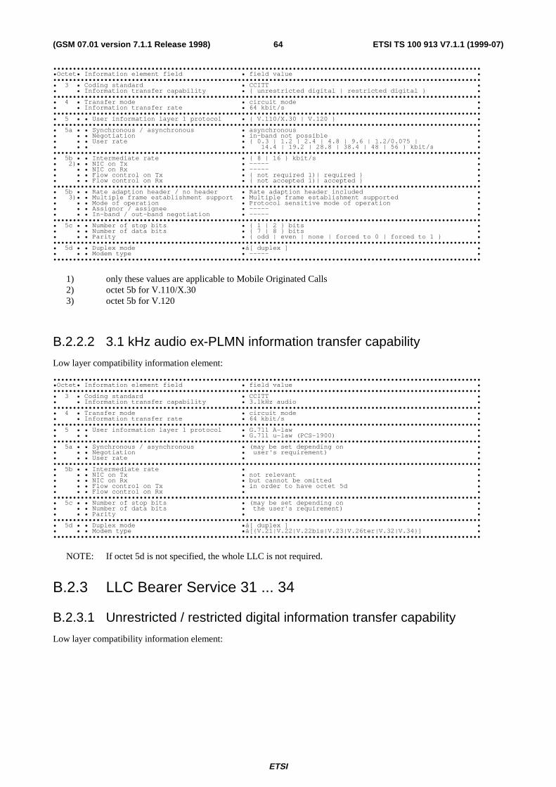
ETSI
ETSI TS 100 913 V7.1.1 (1999-07)64(GSM 07.01 version 7.1.1 Release 1998)
••••••••••••••••••••••••••••••••••••••••••••••••••••••••••••••••••••••••••••••••••••••••••••••••••••••••••••••Octet• Information element field • field value ••••••••••••••••••••••••••••••••••••••••••••••••••••••••••••••••••••••••••••••••••••••••••••••••••••••••••••••• 3 • Coding standard • CCITT •• • Information transfer capability • { unrestricted digital | restricted digital } ••••••••••••••••••••••••••••••••••••••••••••••••••••••••••••••••••••••••••••••••••••••••••••••••••••••••••••••• 4 • Transfer mode • circuit mode •• • Information transfer rate • 64 kbit/s ••••••••••••••••••••••••••••••••••••••••••••••••••••••••••••••••••••••••••••••••••••••••••••••••••••••••••••••• 5 • • User information layer 1 protocol • { V.110/X.30 | V.120 } ••••••••••••••••••••••••••••••••••••••••••••••••••••••••••••••••••••••••••••••••••••••••••••••••••••••••••••••• 5a • • Synchronous / asynchronous • asynchronous •• • • Negotiation • in-band not possible •• • • User rate • { 0.3 | 1.2 | 2.4 | 4.8 | 9.6 | 1.2/0.075 | •• • • • 14.4 | 19.2 | 28.8 | 38.4 | 48 | 56 } kbit/s ••••••••••••••••••••••••••••••••••••••••••••••••••••••••••••••••••••••••••••••••••••••••••••••••••••••••••••••• 5b • • Intermediate rate • { 8 | 16 } kbit/s •• 2)• • NIC on Tx • ----- •• • • NIC on Rx • ----- •• • • Flow control on Tx • { not required 1)| required } •• • • Flow control on Rx • { not accepted 1)| accepted } ••••••••••••••••••••••••••••••••••••••••••••••••••••••••••••••••••••••••••••••••••••••••••••••••••••••••••••••• 5b • • Rate adaption header / no header • Rate adaption header included •• 3)• • Multiple frame establishment support • Multiple frame establishment supported •• • • Mode of operation • Protocol sensitive mode of operation •• • • Assignor / assignee • ----- •• • • In-band / out-band negotiation • ----- ••••••••••••••••••••••••••••••••••••••••••••••••••••••••••••••••••••••••••••••••••••••••••••••••••••••••••••••• 5c • • Number of stop bits • { 1 | 2 } bits •• • • Number of data bits • { 7 | 8 } bits •• • • Parity • { odd | even | none | forced to 0 | forced to 1 } ••••••••••••••••••••••••••••••••••••••••••••••••••••••••••••••••••••••••••••••••••••••••••••••••••••••••••••••• 5d • • Duplex mode •á[ duplex ] •• • • Modem type • ----- ••••••••••••••••••••••••••••••••••••••••••••••••••••••••••••••••••••••••••••••••••••••••••••••••••••••••••••••
1) only these values are applicable to Mobile Originated Calls2) octet 5b for V.110/X.303) octet 5b for V.120
B.2.2.2 3.1 kHz audio ex-PLMN information transfer capability
Low layer compatibility information element:
••••••••••••••••••••••••••••••••••••••••••••••••••••••••••••••••••••••••••••••••••••••••••••••••••••••••••••••Octet• Information element field • field value ••••••••••••••••••••••••••••••••••••••••••••••••••••••••••••••••••••••••••••••••••••••••••••••••••••••••••••••• 3 • Coding standard • CCITT •• • Information transfer capability • 3.1kHz audio ••••••••••••••••••••••••••••••••••••••••••••••••••••••••••••••••••••••••••••••••••••••••••••••••••••••••••••••• 4 • Transfer mode • circuit mode •• • Information transfer rate • 64 kbit/s ••••••••••••••••••••••••••••••••••••••••••••••••••••••••••••••••••••••••••••••••••••••••••••••••••••••••••••••• 5 • • User information layer 1 protocol • G.711 A-law •• • • • G.711 u-law (PCS-1900) ••••••••••••••••••••••••••••••••••••••••••••••••••••••••••••••••••••••••••••••••••••••••••••••••••••••••••••••• 5a • • Synchronous / asynchronous • (may be set depending on •• • • Negotiation • user's requirement) •• • • User rate • ••••••••••••••••••••••••••••••••••••••••••••••••••••••••••••••••••••••••••••••••••••••••••••••••••••••••••••••• 5b • • Intermediate rate • •• • • NIC on Tx • not relevant •• • • NIC on Rx • but cannot be omitted •• • • Flow control on Tx • in order to have octet 5d •• • • Flow control on Rx • ••••••••••••••••••••••••••••••••••••••••••••••••••••••••••••••••••••••••••••••••••••••••••••••••••••••••••••••• 5c • • Number of stop bits • (may be set depending on •• • • Number of data bits • the user's requirement) •• • • Parity • ••••••••••••••••••••••••••••••••••••••••••••••••••••••••••••••••••••••••••••••••••••••••••••••••••••••••••••••• 5d • • Duplex mode •á[ duplex ] •• • • Modem type •á[{V.21|V.22|V.22bis|V.23|V.26ter|V.32|V.34}] ••••••••••••••••••••••••••••••••••••••••••••••••••••••••••••••••••••••••••••••••••••••••••••••••••••••••••••••
NOTE: If octet 5d is not specified, the whole LLC is not required.
B.2.3 LLC Bearer Service 31 ... 34
B.2.3.1 Unrestricted / restricted digital information transfer capability
Low layer compatibility information element:
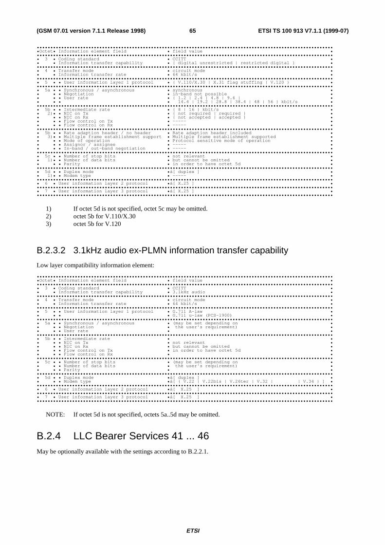
ETSI
ETSI TS 100 913 V7.1.1 (1999-07)65(GSM 07.01 version 7.1.1 Release 1998)
••••••••••••••••••••••••••••••••••••••••••••••••••••••••••••••••••••••••••••••••••••••••••••••••••••••••••••••Octet• Information element field • field value ••••••••••••••••••••••••••••••••••••••••••••••••••••••••••••••••••••••••••••••••••••••••••••••••••••••••••••••• 3 • Coding standard • CCITT •• • Information transfer capability • { digital unrestricted | restricted digital } ••••••••••••••••••••••••••••••••••••••••••••••••••••••••••••••••••••••••••••••••••••••••••••••••••••••••••••••• 4 • Transfer mode • circuit mode •• • Information transfer rate • 64 kbit/s ••••••••••••••••••••••••••••••••••••••••••••••••••••••••••••••••••••••••••••••••••••••••••••••••••••••••••••••• 5 • • User information layer 1 protocol • { V.110/X.30 | X.31 flag stuffing | V.120 } ••••••••••••••••••••••••••••••••••••••••••••••••••••••••••••••••••••••••••••••••••••••••••••••••••••••••••••••• 5a • • Synchronous / asynchronous • synchronous •• • • Negotiation • in-band not possible •• • • User rate • { 1.2 | 2.4 | 4.8 | 9.6 | •• • • • 14.4 | 19.2 | 28.8 | 38.4 | 48 | 56 } kbit/s ••••••••••••••••••••••••••••••••••••••••••••••••••••••••••••••••••••••••••••••••••••••••••••••••••••••••••••••• 5b • • Intermediate rate • { 8 | 16 } kbit/s •• 2)• • NIC on Tx • { not required | required } •• • • NIC on Rx • { not accepted | accepted } •• • • Flow control on Tx • ----- •• • • Flow control on Rx • ----- ••••••••••••••••••••••••••••••••••••••••••••••••••••••••••••••••••••••••••••••••••••••••••••••••••••••••••••••• 5b • • Rate adaption header / no header • Rate adaption header included •• 3)• • Multiple frame establishment support • Multiple frame establishment supported •• • • Mode of operation • Protocol sensitive mode of operation •• • • Assignor / assignee • ----- •• • • In-band / out-band negotiation • ----- ••••••••••••••••••••••••••••••••••••••••••••••••••••••••••••••••••••••••••••••••••••••••••••••••••••••••••••••• 5c • • Number of stop bits • not relevant •• 1)• • Number of data bits • but cannot be omitted •• • • Parity • in order to have octet 5d ••••••••••••••••••••••••••••••••••••••••••••••••••••••••••••••••••••••••••••••••••••••••••••••••••••••••••••••• 5d • • Duplex mode •á[ duplex ] •• 1)• • Modem type • ----- ••••••••••••••••••••••••••••••••••••••••••••••••••••••••••••••••••••••••••••••••••••••••••••••••••••••••••••••• 6 • User information layer 2 protocol •á[ X.25 ] ••••••••••••••••••••••••••••••••••••••••••••••••••••••••••••••••••••••••••••••••••••••••••••••••••••••••••••••• 7 • User information layer 3 protocol •á[ X.25 ] ••••••••••••••••••••••••••••••••••••••••••••••••••••••••••••••••••••••••••••••••••••••••••••••••••••••••••••••
1) If octet 5d is not specified, octet 5c may be omitted.2) octet 5b for V.110/X.303) octet 5b for V.120
B.2.3.2 3.1kHz audio ex-PLMN information transfer capability
Low layer compatibility information element:
••••••••••••••••••••••••••••••••••••••••••••••••••••••••••••••••••••••••••••••••••••••••••••••••••••••••••••••Octet• Information element field • field value ••••••••••••••••••••••••••••••••••••••••••••••••••••••••••••••••••••••••••••••••••••••••••••••••••••••••••••••• 3 • Coding standard • CCITT •• • Information transfer capability • 3.1kHz audio ••••••••••••••••••••••••••••••••••••••••••••••••••••••••••••••••••••••••••••••••••••••••••••••••••••••••••••••• 4 • Transfer mode • circuit mode •• • Information transfer rate • 64 kbit/s ••••••••••••••••••••••••••••••••••••••••••••••••••••••••••••••••••••••••••••••••••••••••••••••••••••••••••••••• 5 • • User information layer 1 protocol • G.711 A-law •• • • • G.711 u-law (PCS-1900) ••••••••••••••••••••••••••••••••••••••••••••••••••••••••••••••••••••••••••••••••••••••••••••••••••••••••••••••• 5a • • Synchronous / asynchronous • (may be set depending on •• • • Negotiation • the user's requirement) •• • • User rate • ••••••••••••••••••••••••••••••••••••••••••••••••••••••••••••••••••••••••••••••••••••••••••••••••••••••••••••••• 5b • • Intermediate rate • •• • • NIC on Tx • not relevant •• • • NIC on Rx • but cannot be omitted •• • • Flow control on Tx • in order to have octet 5d •• • • Flow control on Rx • ••••••••••••••••••••••••••••••••••••••••••••••••••••••••••••••••••••••••••••••••••••••••••••••••••••••••••••••• 5c • • Number of stop bits • (may be set depending on •• • • Number of data bits • the user's requirement) •• • • Parity • ••••••••••••••••••••••••••••••••••••••••••••••••••••••••••••••••••••••••••••••••••••••••••••••••••••••••••••••• 5d • • Duplex mode •á[ duplex ] •• • • Modem type •á[ { V.22 | V.22bis | V.26ter | V.32 | | V.34 } ] ••••••••••••••••••••••••••••••••••••••••••••••••••••••••••••••••••••••••••••••••••••••••••••••••••••••••••••••• 6 • User information layer 2 protocol •á[ X.25 ] ••••••••••••••••••••••••••••••••••••••••••••••••••••••••••••••••••••••••••••••••••••••••••••••••••••••••••••••• 7 • User information layer 3 protocol •á[ X.25 ] ••••••••••••••••••••••••••••••••••••••••••••••••••••••••••••••••••••••••••••••••••••••••••••••••••••••••••••••
NOTE: If octet 5d is not specified, octets 5a..5d may be omitted.
B.2.4 LLC Bearer Services 41 ... 46May be optionally available with the settings according to B.2.2.1.

ETSI
ETSI TS 100 913 V7.1.1 (1999-07)66(GSM 07.01 version 7.1.1 Release 1998)
B.2.5 LLC Bearer Services 51 ... 53
B.2.5.1 Unrestricted digital information transfer capability
Low layer compatibility information element:
••••••••••••••••••••••••••••••••••••••••••••••••••••••••••••••••••••••••••••••••••••••••••••••••••••••••••••••Octet• Information element field • field value ••••••••••••••••••••••••••••••••••••••••••••••••••••••••••••••••••••••••••••••••••••••••••••••••••••••••••••••• 3 • Coding standard • CCITT •• • Information transfer capability • unrestricted digital ••••••••••••••••••••••••••••••••••••••••••••••••••••••••••••••••••••••••••••••••••••••••••••••••••••••••••••••• 4 • Transfer mode • circuit mode •• • Information transfer rate • 64 kbit/s ••••••••••••••••••••••••••••••••••••••••••••••••••••••••••••••••••••••••••••••••••••••••••••••••••••••••••••••• 5 • • User information layer 1 protocol • X.31 flag stuffing ••••••••••••••••••••••••••••••••••••••••••••••••••••••••••••••••••••••••••••••••••••••••••••••••••••••••••••••• 5a • • Synchronous / asynchronous • synchronous •• • • Negotiation • in-band not possible •• • • User rate • { 2.4 | 4.8 | 9.6 | • 14.4 | 19.2 | 28.8 | 38.4 | 48 | 56 } kbit/s•••••••••••••••••••••••••••••••••••••••••••••••••••••••••••••••••••••••••••••••••••••••••••••••••••••••••••••• 6 • User information layer 2 protocol • X.25 ••••••••••••••••••••••••••••••••••••••••••••••••••••••••••••••••••••••••••••••••••••••••••••••••••••••••••••••• 7 • User information layer 3 protocol • X.25 ••••••••••••••••••••••••••••••••••••••••••••••••••••••••••••••••••••••••••••••••••••••••••••••••••••••••••••••
B.2.6 LLC Bearer Service 61
B.2.6.1 3,1 kHz audio ex-PLMN information transfer capability,Asynchronous
Ref. section B.2.2.2.
B.2.6.2 3,1 kHz audio ex-PLMN information transfer capability,Synchronous
Ref. section B.2.3.2.
B.2.7 LLC Bearer Service 81
B.2.7.1 3,1 kHz audio ex-PLMN information transfer capability,Asynchronous
Ref. section B.2.2.2.
B.2.7.2 3,1 kHz audio ex-PLMN information transfer capability,Synchronous
Ref. section B.2.3.2.
B.2.8 HLC Teleservices 11 ... 12High layer compatibility information element:
••••••••••••••••••••••••••••••••••••••••••••••••••••••••••••••••••••••••••••••••••••••••••••••••••••••••••••••Octet• Information element field • Field value ••••••••••••••••••••••••••••••••••••••••••••••••••••••••••••••••••••••••••••••••••••••••••••••••••••••••••••••• 3 • Coding standard • CCITT •• • Interpretation • first high layer characteristic identification to be •• • • used in the call •• • Presentation method of protocol profile • high layer protocol profile ••••••••••••••••••••••••••••••••••••••••••••••••••••••••••••••••••••••••••••••••••••••••••••••••••••••••••••••• 4 • High layer characteristics identific. • Telephony ••••••••••••••••••••••••••••••••••••••••••••••••••••••••••••••••••••••••••••••••••••••••••••••••••••••••••••••

ETSI
ETSI TS 100 913 V7.1.1 (1999-07)67(GSM 07.01 version 7.1.1 Release 1998)
B.2.9 HLC Teleservices 21 ... 23Not applicable.
B.2.10 HLC Teleservice 61High layer compatibility information element:
••••••••••••••••••••••••••••••••••••••••••••••••••••••••••••••••••••••••••••••••••••••••••••••••••••••••••••••Octet• Information element field • Field value ••••••••••••••••••••••••••••••••••••••••••••••••••••••••••••••••••••••••••••••••••••••••••••••••••••••••••••••• 3 • Coding standard • CCITT •• • Interpretation • first high layer characteristic identification to be •• • • used in the call •• • Presentation method of protocol profile • high layer protocol profile ••••••••••••••••••••••••••••••••••••••••••••••••••••••••••••••••••••••••••••••••••••••••••••••••••••••••••••••• 4 • High layer characteristics identific. • Facsimile G2/G3 ••••••••••••••••••••••••••••••••••••••••••••••••••••••••••••••••••••••••••••••••••••••••••••••••••••••••••••••
B.2.11 HLC Teleservice 62High layer compatibility information element:
••••••••••••••••••••••••••••••••••••••••••••••••••••••••••••••••••••••••••••••••••••••••••••••••••••••••••••••Octet• Information element field • Field value ••••••••••••••••••••••••••••••••••••••••••••••••••••••••••••••••••••••••••••••••••••••••••••••••••••••••••••••• 3 • Coding standard • CCITT •• • Interpretation • first high layer characteristic identification to be •• • • used in the call •• • Presentation method of protocol profile • high layer protocol profile ••••••••••••••••••••••••••••••••••••••••••••••••••••••••••••••••••••••••••••••••••••••••••••••••••••••••••••••• 4 • High layer characteristics identific. • Facsimile G2/G3 ••••••••••••••••••••••••••••••••••••••••••••••••••••••••••••••••••••••••••••••••••••••••••••••••••••••••••••••

ETSI
ETSI TS 100 913 V7.1.1 (1999-07)68(GSM 07.01 version 7.1.1 Release 1998)
Annex C (Informative):Change historySMG# SPEC CR PHA VERS NEW_VER SUBJECT
S16 07.01 A004 5.0.0 Data Compression
S17 07.01 A010 2+ 5.0.1 Editorial
S18 07.01 A013 2+ 5.0.1 5.1.0 MT Adapters
S19 07.01 A015 2+ 5.1.0 5.2.0 New GSM Profile for Packet Services
S20 07.01 A016 2+ 5.2.0 5.3.0 Correction for Data Compression
s21 07.01 A017 2+ 5.3.0 5.4.0 V.120 Interworking and RDI
s21 07.01 A018 2+ 5.3.0 5.4.0 Correction of Data Compression
s21 07.01 A019 2+ 5.3.0 5.4.0 HSCSD
s21 07.01 A020 2+ 5.3.0 5.4.0 Support of 14.4 kbit/s (Radio interface related)
s22 07.01 A021 2+ 5.4.0 5.5.0 Provide interworking at higher rates than 28.8 kbit/s (as 33.6 kbit/s).
s22 07.01 A022 2+ 5.4.0 5.5.0 Correction 14.4 and synchronization
s22 07.01 A023 2+ 5.4.0 5.5.0 Initial synchronization for HSCSD
s23 07.01 A023 R96 5.5.0 5.6.0 Initial synchronization for HSCSD
s23 07.01 A024 R96 5.5.0 5.6.0 Corrections for 14.4 kbit/s
s23 07.01 A025 R96 5.5.0 5.6.0 Clarifications on ACC parameter values
s23 07.01 A026 R96 5.5.0 5.6.0 Deletion of codepoint for V.32bis
s24 07.01 A027 R96 5.6.0 5.7.0 Editorial Modification for HSCSD
s24 07.01 A028 R96 5.6.0 5.7.0 Valid combinations of HSCSD parameters
s24 07.01 A029 R96 5.6.0 5.7.0 LLC Handling in GBS
s25 07.01 A030 R96 5.7.0 5.8.0 Setting of ACC, Correction of network behaviour
s25 07.01 A031 R96 5.7.0 5.8.0 UIMI is a negotiable parameter
07.01 5.8.0 5.8.1 Version update for publication
s27 07.01 A032 R98 5.8.1 7.0.0 Synchronisation and V.24 control signal handling in the MT
s28 07.01 A034 R98 7.0.0 7.1.0 Use of Octet 6f of GSM BC
s28 07.01 A035 R98 7.0.0 7.1.0 Improvement of user-initiated service level up and downgrading
s28 07.01 A036 R98 7.0.0 7.1.0 Addition of u-Law for PCS 1900
s29 07.01 7.1.0 7.1.1 Publication of version 7.1.1

ETSI
ETSI TS 100 913 V7.1.1 (1999-07)69(GSM 07.01 version 7.1.1 Release 1998)
History
Document history
V6.0.0 April 1999 Publication
V7.1.1 July 1999 Publication
ISBN 2-7437-3220-2Dépôt légal : Juillet 1999