general operating instructions prominent solenoid · pdf file · 2014-10-28page 4...
TRANSCRIPT
ProM
inen
t®
Part No. 987057 ProMinent Dosiertechnik GmbH · 69123 Heidelberg · Germany BA MAZ 012 08/09 GB
Please read through operating instructions manual carefully before use. Do not discard.The operator shall be liable for any damage caused by installation or operating errors!
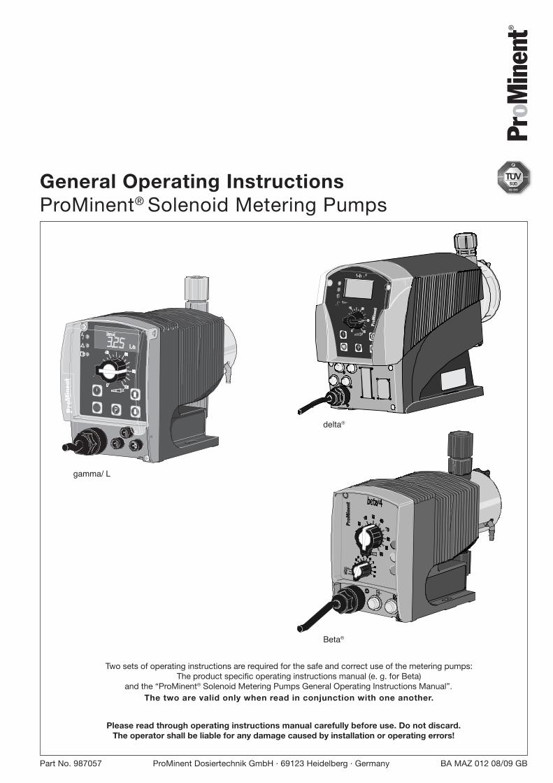
General Operating InstructionsProMinent® Solenoid Metering Pumps
Two sets of operating instructions are required for the safe and correct use of the metering pumps:The product specific operating instructions manual (e. g. for Beta)
and the “ProMinent® Solenoid Metering Pumps General Operating Instructions Manual”.The two are valid only when read in conjunction with one another.
Pro
Min
ent
STOPSTAR
T
T
gamma/ L
Beta®
ProM
inen
t
delta®
BA_MAZ_012_08_09_GB.p65 22.09.2009, 13:10 Uhr1
ProMinent®Page 2
Publishing details
Publishing detailsGeneral Operating Instructions ProMinent® Solenoid Metering Pumps© ProMinent Dosiertechnik GmbH, 2003
Address:ProMinent Dosiertechnik GmbHIm Schuhmachergewann 5-1169123 HeidelbergGermanyTelefon: 06221 842-0Fax: 06221 842-617
We reserve the right to make technical changes.
BA_MAZ_012_08_09_GB.p65 22.09.2009, 13:10 Uhr2
ProMinent® Page 3
Table of contents
Table of contents
General instructions for use ................................................................................................... 4
1 Safety ................................................................................................................................. 5
1.1 Identification of the notes on safety ........................................................................... 5
1.2 Notes on safety .......................................................................................................... 5
2 Assembly and hydraulic installation ................................................................................ 5
2.1 Assembly of the metering pump ................................................................................ 6
2.2 Installing hoses .......................................................................................................... 6
2.2.1 Installation of non self-bleeding pumps ......................................................... 6
2.2.2 Installation of self-bleeding pumps (SEK type) ............................................... 7
2.3 Installation instructions for intake system.................................................................. 8
2.3.1 Notes on the intake side installation ............................................................... 12
2.3.2 Notes on the intake side installation ............................................................... 13
2.3.3 What not to do when installing ....................................................................... 13
2.3.4 Special installation instructions ...................................................................... 14
3 Commissioning ................................................................................................................. 16
3.1 Set precise metering .................................................................................................. 18
4 Accessories ....................................................................................................................... 19
Appendix ............................................................................................................................ 20
Warranty claim form ............................................................................................................ 20
Set-up date form ................................................................................................................. 21
Diagram of system .............................................................................................................. 22
Formular Dekontaminationsbescheinigung ........................................................................ 23
BA_MAZ_012_08_09_GB.p65 22.09.2009, 13:10 Uhr3
ProMinent®Page 4
General instructions for use
Please read the following instructions for use carefully. They will help to get the most use out ofthe operating instructions manual.
The following are particularly highlighted in the text:
• Numbered points
� Instructions
Operating instructions:
NOTE
A note provides important notes for the correct functioning of the unit or is to facilitateyour work.
Notes on safety identified by pictographs (see Chapter 1).
General instructions for use
BA_MAZ_012_08_09_GB.p65 22.09.2009, 13:10 Uhr4
ProMinent® Page 5
1 Safety
1.1 Identification of the notes on safety
The following terms are used in the present operating instructions to indicate the various severitylevels of the danger:
WARNING
• Characterizes a possibly hazardous situation. Your life is in danger and there is a dangerof serious injury if these notes are disregarded!
CAUTION
• Characterizes a possibly hazardous situation. There is a danger of slight or minor injuryor damage to property if these notes are disregarded.
The following warning signs are used in the present operating instructions to indicate differenttypes of the danger:
Warning of danger area.
1.2 Notes on safety
WARNING
• Metering pumps can start to operate as soon as they are connected to the mainspower supply.Ensure that no hazardous media can leak out.If you have not done so, press the Stop/Start button or disconnect the metering pumpfrom the mains immediately.
• The metering pump cannot be switched off.In the case of an electrical accident, disconnect the power cable from the mains powersupply.
• Disconnect the power cable from the mains power supply before working on themetering pump.
• Always depressurise liquid end before working on the metering pump.
• Always empty and rinse the liquid end before working on the metering pump if usedwith hazardous or unknown feed chemicals.
• Pumps for radioactive media may not be sent by post.
CAUTION
• It is not permitted to assemble and install ProMinent® metering pumps with non-genuine parts which have not been checked and recommended by ProMinent. It canendanger people and property in circumstances for which we are not liable.
• Note the resistances of pump materials when metering aggressive media (seeProMinent® resistance list in the Product Catalogue or at www.prominent.com).
• If fitting a different liquid end size, the pump must be reprogrammed at the factory.The pump delta® can be reprogrammed in the SYSTEM menu.
• Note all national directives which apply to the installation.
2 Assembly and hydraulic installation
WARNING
• The metering pumps must be commissioned precisely in accordance with theinstructions in the operating instructions manual.
• Assembly and installation of ProMinent® pumps with non-original parts that have notbeen checked and recommended by ProMinent.
• Always depressurise lines before working on the metering pump. Empty and rinse outthe liquid end.
Safety / Assembly and hydraulic installation
BA_MAZ_012_08_09_GB.p65 22.09.2009, 13:10 Uhr5
ProMinent®Page 6
Assembly and hydraulic installation
• Never operate the metering pump against a closed stop valve on the discharge side.The discharge line could rupture.
• Empty any water out of the liquid end upstream before commissioning, or rinse outwith a suitable solvent, if you are using media which may not come into contact withwater (see p.14, “Dewatering liquid end”).
• Note all national directives which apply to the installation.
2.1 Assembly of the metering pump
CAUTION
• Once installed, the metering pump must not vibrate.
• Priming and discharge valves must be vertical (bleed valve in the case of self-bleedingliquid end).
• Ensure easy access for operation and maintenance.
The metering pump must be mounted with the pedestal resting on a firm horizontal surface.(Use screws M5).
2.2 Installing hoses
NOTE
Installation instructions for tubing system, see section 2.3.
2.2.1 Installation of non self-bleeding pumps
CAUTION
• Once fitted, hoses must not be kinked or subject to mechanical stress.
• When metering extremely aggressive or hazardous media we recommend bleeding withreturn feed into the supply tank and shut off valves on the discharge and intake sides.
• To ensure the durability of the connections, always use correctly-sized circlips andhose nozzles.
• Always use original hoses of the specified diameter and wall thickness.• Do not exceed the maximum admissible pump priming pressure (see product-specific
operating instructions).• Ensure operating pressure for the metering pump and the tubing system does not
exceed the maximum admissible level (see product-specific operating instructions andyour system documentation).
NOTE
Fit tubing so that the metering pump and the liquid end can be removed sideways ifnecessary.
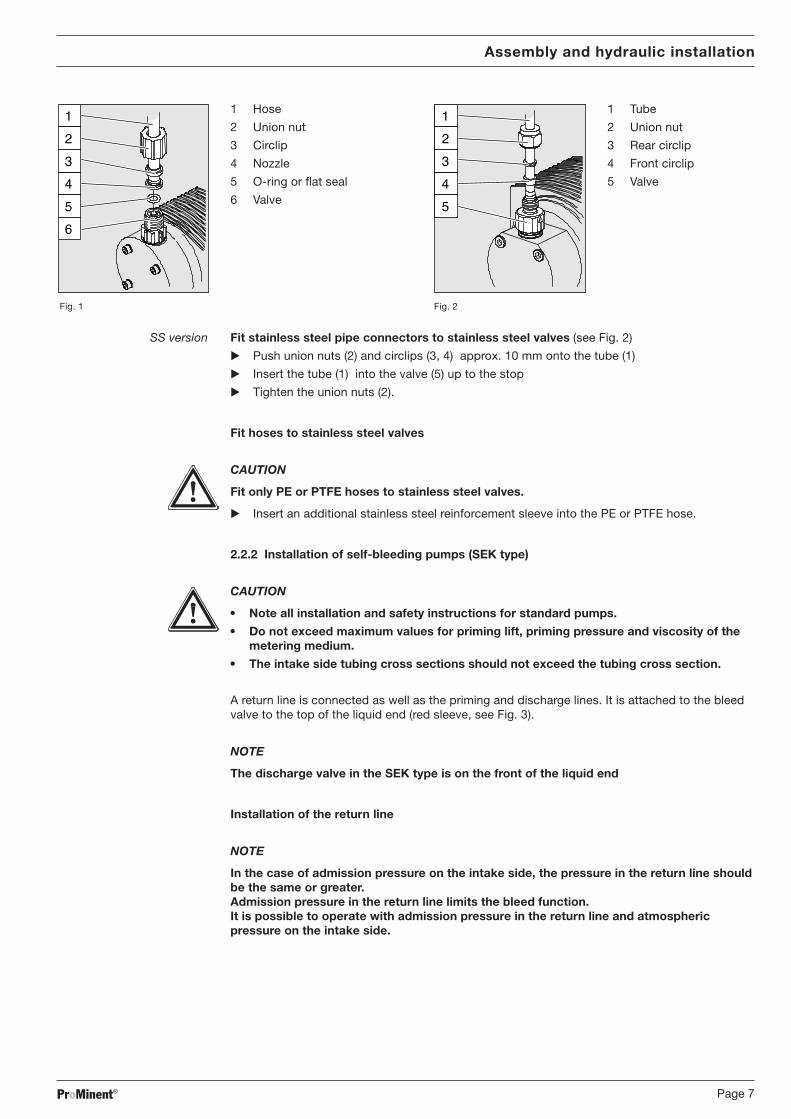
PP, NP, PV, TT versions Fit hoses to plastic valves (see Fig. 1)
� Cut ends of hoses straight across� Pull the union nut (2) and the circlip (3) over the hose (1)� Push the end of the hose (1) over the nozzle (4) as far as the stop, widen if necessary� Ensure that the O-ring (5) or flat seal is seated correctly in the valve (6)
NOTE
With the PV design, the FPM flat seal has one point as distinct from the EPDM flat seal.
� Fit the tubing (1) with the nozzle (4) to the valve (6)� Clamp the hose connector:
tighten the union nut (2) while pressing onto the tubing (1)� Retighten the hose connector:
pull briefly on the hose (1) connected to the liquid end and tighten the union nut (2) oncemore.
BA_MAZ_012_08_09_GB.p65 22.09.2009, 13:10 Uhr6
ProMinent® Page 7
1
2
4
5
6
3
1 Hose 1
2
4
5
3
1 Tube
2 Union nut 2 Union nut
3 Circlip 3 Rear circlip
4 Nozzle 4 Front circlip
5 O-ring or flat seal 5 Valve
6 Valve
Fig. 1 Fig. 2
SS version Fit stainless steel pipe connectors to stainless steel valves (see Fig. 2)
� Push union nuts (2) and circlips (3, 4) approx. 10 mm onto the tube (1)
� Insert the tube (1) into the valve (5) up to the stop
� Tighten the union nuts (2).
Fit hoses to stainless steel valves
CAUTION
Fit only PE or PTFE hoses to stainless steel valves.
� Insert an additional stainless steel reinforcement sleeve into the PE or PTFE hose.
2.2.2 Installation of self-bleeding pumps (SEK type)
CAUTION
• Note all installation and safety instructions for standard pumps.
• Do not exceed maximum values for priming lift, priming pressure and viscosity of themetering medium.
• The intake side tubing cross sections should not exceed the tubing cross section.
A return line is connected as well as the priming and discharge lines. It is attached to the bleedvalve to the top of the liquid end (red sleeve, see Fig. 3).
NOTE
The discharge valve in the SEK type is on the front of the liquid end
Installation of the return line
NOTE
In the case of admission pressure on the intake side, the pressure in the return line shouldbe the same or greater.Admission pressure in the return line limits the bleed function.It is possible to operate with admission pressure in the return line and atmosphericpressure on the intake side.
Assembly and hydraulic installation
BA_MAZ_012_08_09_GB.p65 22.09.2009, 13:10 Uhr7

ProMinent®Page 8
Assembly and hydraulic installation
� Attach the hose to the return hose nozzle and/or to the bleed valve of the self-bleeding liquidend (PVC hose, soft, 6x4 recommended)
� Feed the free end back into the supply tank.
� Cut the return line so that the end does not reach the feed chemical.
Fig. 3
2.3 Installation instructions for intake system
CAUTION
• Fit a pressure gauge connector to enable checking of the pressure-ratios in the tubingsystem near the intake connector and of the discharge connector.
• Connect pipes to the pump ensuring that there are no forces exerted on the pump, e.g.movement, weight or line expansion.Always use a flexible length of tubing to connect steel pipes to plastic liquid ends.
Bleed valve for the return line in the supplytank, 6/4 mm
Red sleeve
Discharge valve for discharge line at the injectionpoint, 6/4 - 12/9 mm
Intake valve for intake line in supply tank,6/4 - 12/9 mm
BA_MAZ_012_08_09_GB.p65 22.09.2009, 13:10 Uhr8
ProMinent® Page 9
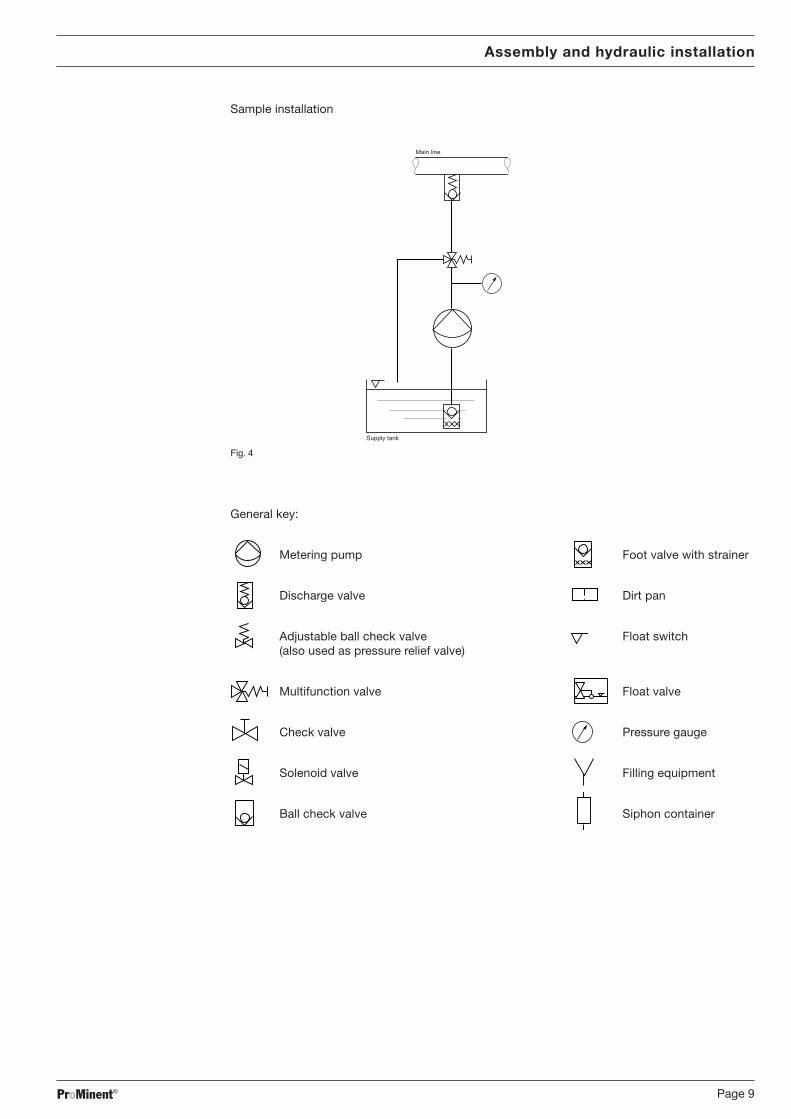
Sample installation
Main line
Supply tank
Fig. 4
General key:
Metering pump Foot valve with strainer
Discharge valve Dirt pan
Adjustable ball check valve Float switch(also used as pressure relief valve)
Multifunction valve Float valve
Check valve Pressure gauge
Solenoid valve Filling equipment
Ball check valve Siphon container
Assembly and hydraulic installation
charge line at the injection
BA_MAZ_012_08_09_GB.p65 22.09.2009, 13:10 Uhr9

ProMinent®Page 10
Assembly and hydraulic installation
B
E
I
C
G
H
A
F
D
BA_MAZ_012_08_09_GB.p65 22.09.2009, 13:10 Uhr10
ProMinent® Page 11
Assembly and hydraulic installation
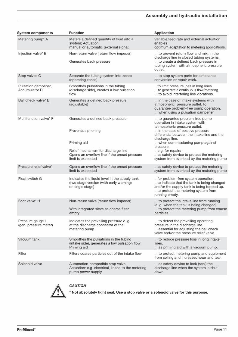
System components Function Application
Metering pump* A Meters a defined quantity of fluid into a Variable feed rate and external actuationsystem; Actuation: enablesmanual or automatic (external signal) optimum adaptation to metering applications.
Injection valve* B Non-return valve (return flow impeder) ... to prevent return flow and mix. in thedischarge line in closed tubing systems.
Generates back pressure ... to create a defined back pressure intubing system with atmospheric pressureoutlet.
Stop valves C Separate the tubing system into zones ... to stop system parts for aintenance,(operating zones) conversion or repair work.
Pulsation dampener, Smoothes pulsations in the tubing .. to limit pressure loss in long lines.Accumulator D (discharge side), creates a low pulsation ... to generate a continuous flow/metering.
flow ... to avoid interfering line vibrations.
Ball check valve* E Generates a defined back pressure ... in the case of intake systems with(adjustable) atmospheric pressure outlet, to
guarantee problem-free pump operation.... when using a pulsation dampener
Multifunction valve* F Generates a defined back pressure ... to guarantee problem-free pumpoperation in intake system with atmospheric pressure outlet.
Prevents siphoning ... in the case of positive pressuredifferential between the intake line and thedischarge line.
Priming aid ... when commissioning pump againstpressure.
Relief mechanism for discharge line ...e.g. for repairsOpens an overflow line if the preset pressure ...as safety device to protect the meteringlimit is exceeded system from overload by the metering pump
Pressure relief valve* Opens an overflow line if the preset pressure ...as safety device to protect the meteringlimit is exceeded system from overload by the metering pump
Float switch G Indicates the liquid level in the supply tank ...for problem-free system operation.(two stage version (with early warning) ...to indicate that the tank is being changedor single stage) and/or the supply tank is being topped up.
...to protect the metering system fromrunning empty.
Foot valve* H Non-return valve (return flow impeder) ... to protect the intake line from running(e. g. when the tank is being changed).
With integrated sieve as coarse filter ... to protect the metering pump from coarseempty particles.
Pressure gauge I Indicates the prevailing pressure e. g. ... to detect the prevailing operating(gen. pressure meter) at the discharge connector of the pressure in the discharge line.
metering pump ... essential for adjusting the ball checkvalve and/or the pressure relief valve.
Vacuum tank Smoothes the pulsations in the tubing ... to reduce pressure loss in long intake(intake side), generates a low pulsation flow lines.Priming aid ... as priming aid with a vacuum pump.
Filter Filters coarse particles out of the intake flow ... to protect metering pump and equipmentfrom soiling and increased wear and tear.
Solenoid valve Automation-compatible stop valve ... as safety device to lock (seal) theActuation: e.g. electrical, linked to the metering discharge line when the system is shutpump power supply down.
CAUTION
* Not absolutely tight seal. Use a stop valve or a solenoid valve for this purpose.
BA_MAZ_012_08_09_GB.p65 22.09.2009, 13:10 Uhr11
ProMinent®Page 12
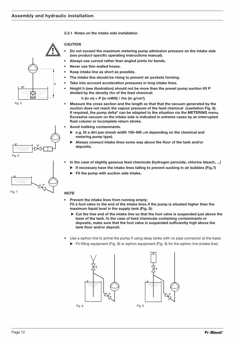
2.3.1 Notes on the intake side installation
CAUTION
• Do not exceed the maximum metering pump admission pressure on the intake side(see product-specific operating instructions manual).
�
���� �
• Always use curved rather than angled joints for bends.
• Never use thin-walled hoses.
• Keep intake line as short as possible.
• The intake line should be rising to prevent air pockets forming.
• Take into account acceleration pressures in long intake lines.
• Height h (see illustration) should not be more than the preset pump suction lift Pdivided by the density rho of the feed chemical:
h (in m) = P (in mWS) / rho (in g/cm3).
• Measure the cross section and the length so that that the vacuum generated by thesuction does not reach the vapour pressure of the feed chemical (cavitation Fig. 6).If required, the pump delta® can be adapted to the situation via the METERING menu.Excessive vacuum on the intake side is indicated in extreme cases by an interruptedfluid column or incomplete return stroke.
• Avoid inatking contaminants.
� e.g. fit a dirt pan (mesh width 100-400 µm depending on the chemical andmetering pump type).
� Always connect intake lines some way above the floor of the tank and/ordeposits.
• In the case of slightly gaseous feed chemicals (hydrogen peroxide, chlorine bleach, ...)
� If necessary have the intake lines falling to prevent sucking in air bubbles (Fig.7)
� Fit the pump with suction side intake.
NOTE
• Prevent the intake lines from running empty:Fit a foot valve to the end of the intake lines if the pump is situated higher than themaximum liquid level in the supply tank (Fig. 5):
� Cut the free end of the intake line so that the foot valve is suspended just above thebase of the tank. In the case of feed chemicals containing contaminants ordeposits, make sure that the foot valve is suspended sufficiently high above thetank floor and/or deposit.
• Use a siphon line to prime the pump if using deep tanks with no pipe connector at the base:
� Fit filling equipment (Fig. 8) or siphon equipment (Fig. 9) for the siphon line (intake line).
���� � ���� �
���� �
Assembly and hydraulic installation
���� �
BA_MAZ_012_08_09_GB.p65 22.09.2009, 13:10 Uhr12
ProMinent® Page 13
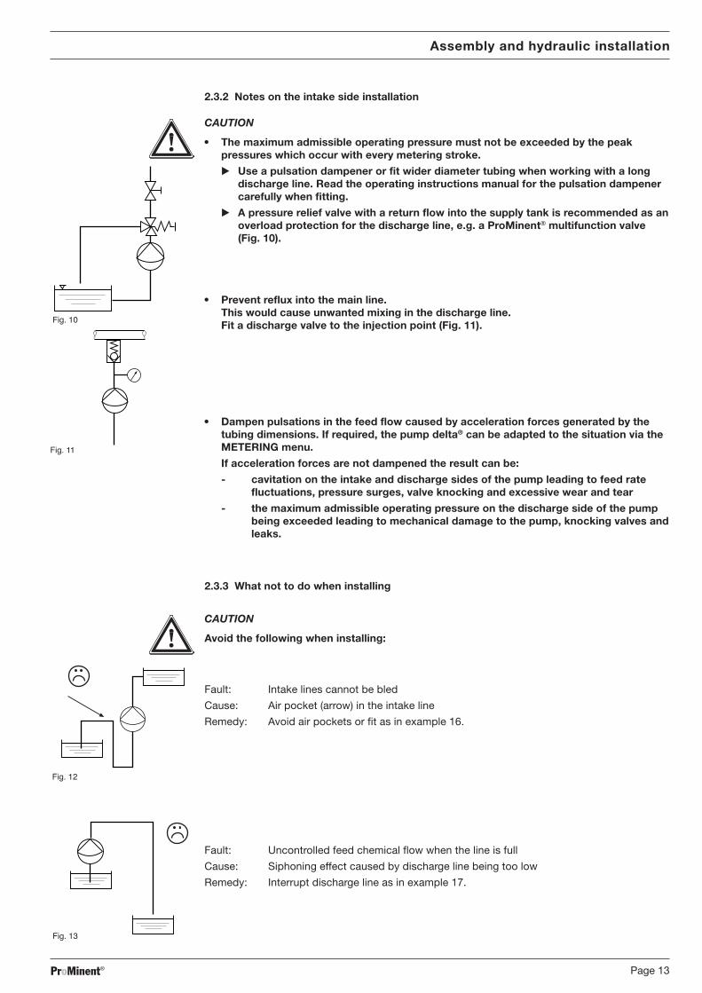
2.3.2 Notes on the intake side installation
CAUTION
• The maximum admissible operating pressure must not be exceeded by the peakpressures which occur with every metering stroke.
� Use a pulsation dampener or fit wider diameter tubing when working with a longdischarge line. Read the operating instructions manual for the pulsation dampenercarefully when fitting.
� A pressure relief valve with a return flow into the supply tank is recommended as anoverload protection for the discharge line, e.g. a ProMinent® multifunction valve(Fig. 10).
• Prevent reflux into the main line.This would cause unwanted mixing in the discharge line.Fit a discharge valve to the injection point (Fig. 11).
• Dampen pulsations in the feed flow caused by acceleration forces generated by thetubing dimensions. If required, the pump delta® can be adapted to the situation via theMETERING menu.
If acceleration forces are not dampened the result can be:
- cavitation on the intake and discharge sides of the pump leading to feed ratefluctuations, pressure surges, valve knocking and excessive wear and tear
- the maximum admissible operating pressure on the discharge side of the pumpbeing exceeded leading to mechanical damage to the pump, knocking valves andleaks.
2.3.3 What not to do when installing
CAUTION
Avoid the following when installing:
���� ��
Fault: Intake lines cannot be bled
Cause: Air pocket (arrow) in the intake line
Remedy: Avoid air pockets or fit as in example 16.
Fault: Uncontrolled feed chemical flow when the line is full
Cause: Siphoning effect caused by discharge line being too low
Remedy: Interrupt discharge line as in example 17.
���� ��
���� ��
Assembly and hydraulic installation
���� ��
BA_MAZ_012_08_09_GB.p65 22.09.2009, 13:10 Uhr13
ProMinent®Page 14
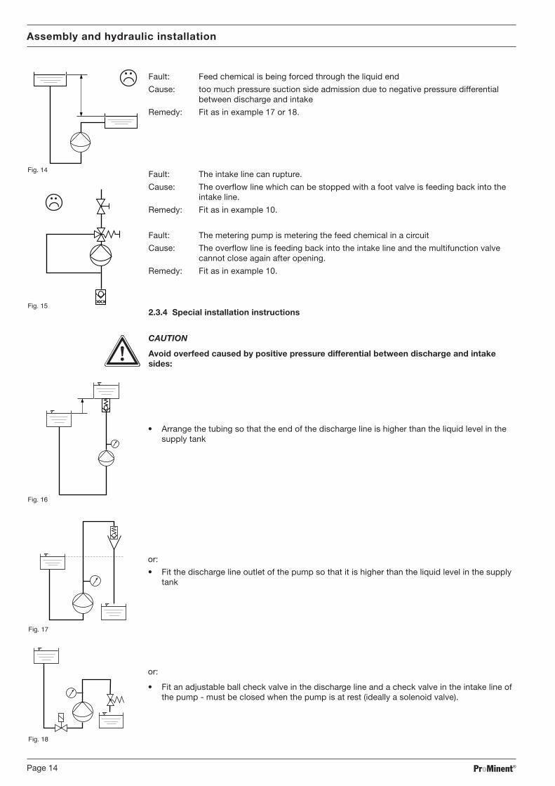
Fault: Feed chemical is being forced through the liquid end
Cause: too much pressure suction side admission due to negative pressure differentialbetween discharge and intake
Remedy: Fit as in example 17 or 18.
Fault: The intake line can rupture.
Cause: The overflow line which can be stopped with a foot valve is feeding back into theintake line.
Remedy: Fit as in example 10.
Fault: The metering pump is metering the feed chemical in a circuit
Cause: The overflow line is feeding back into the intake line and the multifunction valvecannot close again after opening.
Remedy: Fit as in example 10.
2.3.4 Special installation instructions
CAUTION
Avoid overfeed caused by positive pressure differential between discharge and intakesides:
���� ��
• Arrange the tubing so that the end of the discharge line is higher than the liquid level in thesupply tank
or:
���� ��
• Fit the discharge line outlet of the pump so that it is higher than the liquid level in the supplytank
or:
���� ��
• Fit an adjustable ball check valve in the discharge line and a check valve in the intake line ofthe pump - must be closed when the pump is at rest (ideally a solenoid valve).
Assembly and hydraulic installation
���� ��
���� ��
BA_MAZ_012_08_09_GB.p65 22.09.2009, 13:10 Uhr14
ProMinent® Page 15
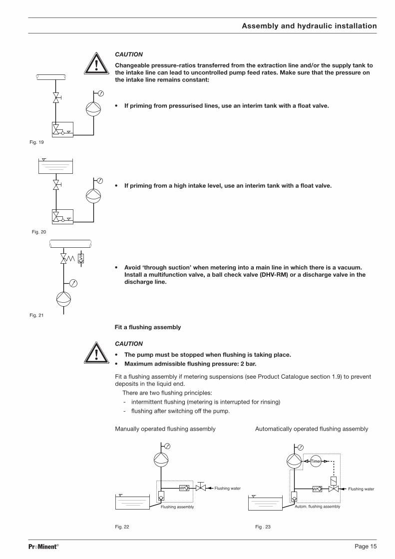
CAUTION
Changeable pressure-ratios transferred from the extraction line and/or the supply tank tothe intake line can lead to uncontrolled pump feed rates. Make sure that the pressure onthe intake line remains constant:
���� ��
• If priming from pressurised lines, use an interim tank with a float valve.
• If priming from a high intake level, use an interim tank with a float valve.
���� ��
• Avoid ‘through suction’ when metering into a main line in which there is a vacuum.Install a multifunction valve, a ball check valve (DHV-RM) or a discharge valve in thedischarge line.
Fit a flushing assembly
CAUTION
• The pump must be stopped when flushing is taking place.
• Maximum admissible flushing pressure: 2 bar.
Fit a flushing assembly if metering suspensions (see Product Catalogue section 1.9) to preventdeposits in the liquid end.
There are two flushing principles:
- intermittent flushing (metering is interrupted for rinsing)
- flushing after switching off the pump.
Manually operated flushing assembly Automatically operated flushing assembly
Flushing water
Flushing assembly
Fig. 22 Fig . 23
Assembly and hydraulic installation
���� ��
Flushing water
Timer
Autom. flushing assembly
BA_MAZ_012_08_09_GB.p65 22.09.2009, 13:10 Uhr15
ProMinent®Page 16
3 Commissioning
WARNING
• Protect yourself when handling hazardous feed chemicals.
• If using with media which may not come into contact with water, remove all tracesfrom the liquid end before installation.(Procedure, see below. The liquid end may contain traces of water from the factorytests.)
• After long periods out of commission the metering pump cannot be guaranteed to beabsolutely reliable as the feed chemical can crystallise in the valves and on thediaphragm. You must carry out regular checks on the valves and the diaphragm (seeproduct-specific operating instructions).
• Check pump connections for tightness.
• Check suction valve and pressure valve for leakages and retighten, if required!
• Check liquid end for leakages and retighten liquid end screw, if required!
• Check that coarse and fine bleed valves are closed are (See also “Fine bleeding”).
NOTE
• Set the stroke length only while the pump is running.
• The metering pump should prime at 100 % stroke length as the priming lift isdependent on the lift volume if the liquid end is empty. If the metering pump has toprime at a lower stroke length and does not do so, select a correspondingly lowerpriming lift.
• SEK type: The suction lift corresponds to the priming lift because with gaseous mediasome gas always remains inside the liquid end.
• Retighten liquid end screws after 24 hours in operation).
Screw tightening torque: 4,5 to 5 Nm
Emptying liquid end Remove all water if working with media which cannot come into contact with water:
� Rotate the pump until the discharge connector is pointing downwards
� Let the water run out of the liquid end
� Blow out from above through the intake connector using suitable equipment or withcompressed air.
Filling liquid end
WARNING
Protect yourself when handling hazardous feed chemicals.
In this method, some feed chemical will emerge from the discharge valve.
Liquid ends without coarse/fine bleed valves:
� Connect the intake line to the liquid end, but not the discharge line
� Connect a short, transparent hose section to the discharge valve
� Switch on the metering pump and run at maximum stroke length and stroke rate until the li-quid end is full and contains no bubbles (some feed chemical will be visible in the short hosesection.)
� Switch off the metering pump
� Connect the discharge line to the liquid end.
The metering pump is ready to run.
Commissioning
BA_MAZ_012_08_09_GB.p65 22.09.2009, 13:10 Uhr16
ProMinent® Page 17
Liquid ends with coarse/fine bleed valves:
� Connect the intake and discharge line to the liquid end
� Connect the return line
� Open the bleed valve by turning the star knob anti-clockwise;This opens the passage for coarse bleeding via the return line
� Switch on the metering pump and run at maximum stroke length and stroke rate until theliquid end is full and contains no bubbles (some feed chemical will be visible in the returnline or the discharge line)
� Close the bleed valve (turn clockwise)
� The metering pump will stop.
The metering pump is ready to run.
NOTE
• If metering gaseous feed chemicals you should feed a constant partial flow of themetering volume back into the supply tank. The return flow should amount to approx.20 % of the metering volume.
• The feed chemical must be low-viscosity and contain no suspended solids.
• The return line should end above the liquid level. The fine bleed valve then acts asa vacuum breaker. This prevents the supply tank from being sucked dry if a vacuumoccurs in the discharge line.
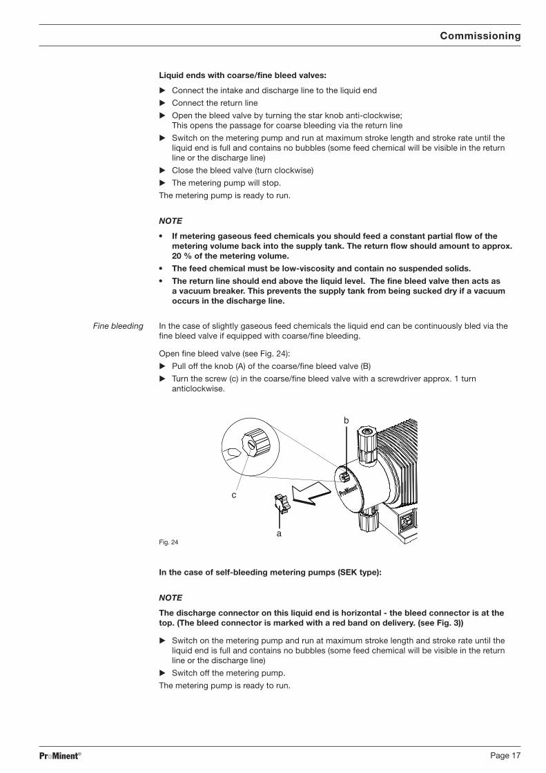
Fine bleeding In the case of slightly gaseous feed chemicals the liquid end can be continuously bled via thefine bleed valve if equipped with coarse/fine bleeding.
Open fine bleed valve (see Fig. 24):
� Pull off the knob (A) of the coarse/fine bleed valve (B)
� Turn the screw (c) in the coarse/fine bleed valve with a screwdriver approx. 1 turnanticlockwise.
�
�
�
ProMinent�
Fig. 24
In the case of self-bleeding metering pumps (SEK type):
NOTE
The discharge connector on this liquid end is horizontal - the bleed connector is at thetop. (The bleed connector is marked with a red band on delivery. (see Fig. 3))
� Switch on the metering pump and run at maximum stroke length and stroke rate until theliquid end is full and contains no bubbles (some feed chemical will be visible in the returnline or the discharge line)
� Switch off the metering pump.
The metering pump is ready to run.
Commissioning
BA_MAZ_012_08_09_GB.p65 22.09.2009, 13:10 Uhr17

ProMinent®Page 18
3.1 Set precise metering
NOTE
• Choose the largest possible stroke length for gaseous media.
• Select the largest possible stroke rate to ensure good mixing.
• For reproducibility in the case of proportional metering set a stroke length of at least30 % (SEK type: not less than 50 %).
Diagram for setting the feed rate
General notes about stroke length and stroke rate
� Open at the page with the diagram for your pump type (see product-specific operatinginstructions manual)
� Determine the correction factor. Mark the operating pressure for your application in the diagram entitled “Correction factor depending on operating pressure”
� Trace a vertical line from the defined value up to the curve and then horizontally to the leftand read off the correction factor
� Divide the required feed rate by the defined correction factor and mark this value (l/h) on the“l/h” axis in the diagram entitled “Feed rate depending on stroke length and stroke rate“
� Trace a horizontal line from this point to the left. Trace another vertical line from theintersections with the straight lines for the variable stroke rate down to the “Stroke length”axis
� Set the metering pump to one of the stroke rates and the associated stroke lengthdetermined in this way.
The measurements for determining the pump capacity for the relevant diagrams have beenconducted using water and the stroke length correction factor has been set at 70 %.
Commissioning
BA_MAZ_012_08_09_GB.p65 22.09.2009, 13:10 Uhr18
ProMinent® Page 19
4 Accessories
CAUTION
It is not permitted to assemble and install ProMinent® metering pumps with non-genuineparts which have not been checked and recommended by ProMinent. This can endangerpeople and property in circumstances for which we are not liable.
Float switches2-stage with 2 m connection cable.
Fault-indicating relayindicates faults
Fault indicating and pacing relayindicates faults and supplies pulses for other devices.
Signal cableUniversal-signal 5-core / 2 m, 5 m and 10 m
External contact cable 2-core / 2 m, 5 m and 10 m
Foot valveswith suction filter and non-return valve for connection to end of the intake line.
Discharge valveswith spring-loaded non-return valve for metering in open or closed systems and for attachingdischarge line.
Injection lancesfor metering into large pipe cross sections and for preventing blockages of crystallising media.
Multifunction valvefor fitting directly to pump head with the following functions:ball check valve, pressure relief valve, priming aid, relief of discharge line
Back pressure valvesFor reproducible metering at low operating pressure or as overflow bypass valve.
Accumulatorsfor pulsation dampening in the case of e.g. long discharge lines.
Feed monitorsfor monitoring the feed rate. After a preset number of un-acknowledged metering strokes a faultis indicated and the metering pump is switched off.
Suction lanceswith foot valve and float switch for disposable drums or supply tanks.
Flushing assemblyfor flushing and cleaning liquid end, discharge line and discharge valve.Manual or automatic, timer clock controlled versions.
Supply tankfrom 35 to 1000 l capacity with locking screw cap and all necessary accessories.
Manual/electric stirrersfor mixing and batching metering solutions
Consolesfor stable pump assembly.
Accessories
BA_MAZ_012_08_09_GB.p65 22.09.2009, 13:10 Uhr19

ProMinent®Page 20
Please copy and send with the pump!In the case of failure of the metering pump within the warranty period
please clean the pumpand send it back with a completed warranty claim.
Company: ............................................................................. Phone No.: ................................... Date: ........................................
Address: .........................................................................................................................................................................................
Person responsible (customer): ......................................................................................................................................................
Order-No.: ......................................................................... Delivery-Date: ......................................................................................
Pump-type/Identcode: .......................................................... Serial. No.: ......................................................................................
Short description of fault ................................................................................................................................................................
........................................................................................................................................................................................................
........................................................................................................................................................................................................
Type of fault
1 Mechanical fault 2 Electrical fault
Atypical wear and tear Loose connector, e.g. plug or cable
Consumables Controls (e. g. switch)
Breakage/other damage Controller
Corrosion
Damage in transit
3 Leakage 4 No feed or poor feed
Connectors Diaphragm faulty
Liquid end Other
Application conditions:
Where used/description of equipment: ..........................................................................................................................................
Accessories used: ..........................................................................................................................................................................
........................................................................................................................................................................................................
........................................................................................................................................................................................................
........................................................................................................................................................................................................
Commissioned (Date): ....................................................................................................................................................................
Run-time (approx. operating hours ): ..............................................................................................................................................
Warranty claim form
Please complete in full.
Warranty claim for pump No.
BA_MAZ_012_08_09_GB.p65 22.09.2009, 13:10 Uhr20

ProMinent® Page 21
Pump Type – ......................................................
Feed rate l/h ......................................................
Stroke rate Strokes/min ......................................................
Stroke length % ......................................................
Valve spring pressure, suction side bar ......................................................
Valve spring pressure, Discharge side bar ......................................................
Medium Description/concentration – / % ............................ / .......................
Suspended solids content/particle size % / mm ............................ / .......................
Material solid/hardness class – / (Mohs scale) ............................ / .......................
Dynamic viscosity mPa s (cP) ......................................................
Density kg/m3 ......................................................
Vapour pressure at operating temperature bar / °C ............................ / .......................
Equipment, intake side Pressure in the suction tank bar ......................................................
Set width, intake line DN / mm ............................ / .......................
Suction lift, min./max. m ............................ / .......................
Intake height, min./max. m ............................ / .......................
Length of intake line m ......................................................
Number of angles/valves – / – ............................ / .......................
Pulsation dampener Accumulator with diaphragm .... ltr.
Accumulator .............................. ltr.
Equipment Static system pressure, min./max. bar ............................ / .......................
Set width discharge line DN/mm ......................................................
Length of discharge line m ......................................................
Feed lift m ......................................................
Number of angles/valves – / – ............................ / .......................
Pulsation dampener Accumulator with diaphragm .... ltr.
Accumulator .............................. ltr.
Customer:
Project-No.: Date: diagram included:
Set-up date form
BA_MAZ_012_08_09_GB.p65 22.09.2009, 13:10 Uhr21
ProMinent®Page 22
Customer: ............................................................................................................................................................................................................................................................................................
Project-No.: ................................................................................................................................................................. Date: ..................................................................................................
Diagram of system
BA_MAZ_012_08_09_GB.p65 22.09.2009, 13:10 Uhr22
ProMinent® Page 23
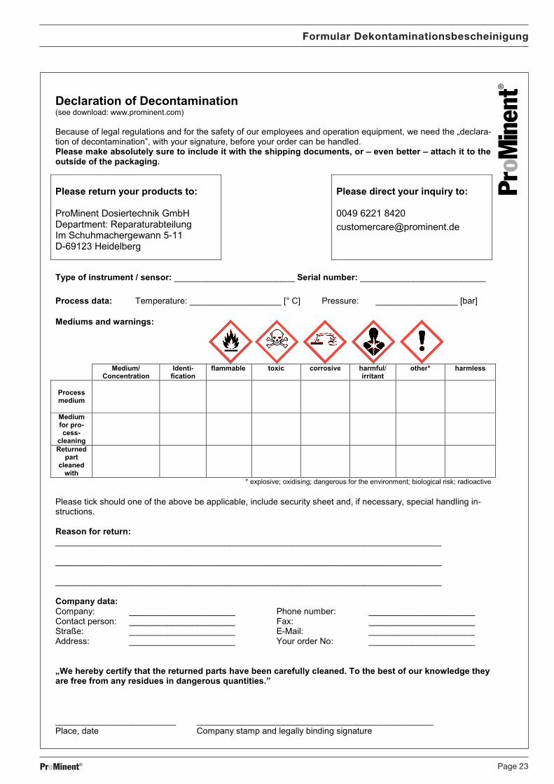
Formular Dekontaminationsbescheinigung
BA_MAZ_012_08_09_GB.p65 22.09.2009, 13:10 Uhr23

ProMinent®
Anschriften- und Liefernachweis durch den Hersteller /Addresses and delivery through manufacturer /Adresses et liste des fournisseurs fournies par le constructeur /Para informarse de las direcciones de los distribuidores, dirigirse al fabricante:
ProMinent Dosiertechnik GmbHIm Schuhmachergewann 5-1169123 HeidelbergGermany
Tel.: +49 6221 842-0Fax: +49 6221 842-419
Anschr_Lief_Herst_A4_4spr.p65 29.07.2009, 10:34 Uhr2