general product description - valser · general product description 2 index 1 valve identification...
TRANSCRIPT
DELLA FOGLIA s.a.s. Viale Kennedy, 149 Tel. : +39 0331-602059 Fax : +39 0331-604249
e-mail : [email protected]
GENERAL PRODUCT DESCRIPTION
GENERAL PRODUCT DESCRIPTION
2
IINNDDEEXX 1 VALVE IDENTIFICATION TABLE 2 FLOATING BALL VALVES 3 TRUNNION MOUNTED BALL VALVES 4 TOP ENTRY BALL VALVES 5 COMBINED BALL VALVES 6 MATERIALS 7 VALVE DATA SHEET 8 GLOSSARY 9 SYMBOLS AND ABBREVIATIONS 10 STANDARD AND CODES

GENERAL PRODUCT DESCRIPTION
3
11 VVAALLVVEE IIDDEENNTTIIFFIICCAATTIIOONN TTAABBLLEE
FLOATING BALL VALVES MOD. BODY JOINT TYPE SERVICE SIZE-PRESSURE
RANGE SEALS OPTIONAL REQUIREMENTS
AB BOLTED BODY 2 or 3 PIECES GENERAL SERVICE
1/2" ÷ 8" CLASS 150 ÷ 2500
Ends : RF-BW-RTJ-HUB-SW-NPT
GRAPHITE - BARE STEM - DRAIN
AA BOLTED BODY 2 or 3 PIECES
LOW TEMPER./ CRYOGENIC
SERVICE
1/2" ÷ 6" CLASS 150 ÷ 2500
Ends: RF-BW-RTJ-HUB-SW-NPT
GRAPHITE - BARE STEM - DRAIN
AC BOLTED BODY 2 or 3 PIECES GENERAL SERVICE
1/2" ÷ 6" CLASS 150 ÷ 2500
Ends : INTEGRAL PUPS GRAPHITE - BARE STEM
- DRAIN
AY BOLTED BODY 2 or 3 PIECES
- LOW TEMPER. - CRYOGENIC
SERVICE
1/4" ÷ 2" CLASS 800 ÷ 6000
Ends:INTEGRAL PUPS (100 mm)
GRAPHITE - BARE STEM - DRAIN
AM BOLTED BODY 2 or 3 PIECES GENERAL SERVICE
1/2" ÷ 60" CLASS 150 ÷ 2500
Ends : RF-BW-RTJ-HUB-SW-NPT
GRAPHITE METAL/METAL
- BARE STEM - DRAIN
AF TRHEADED BODY 2 PIECES GENERAL SERVICE
1/4" ÷ 2" CLASS 800 ÷ 6000
Ends : NPT-SW-WELDED PUPS
GRAPHITE -
AI TRHEADED BODY 2 PIECES GENERAL SERVICE
1/4" ÷ 2" CLASS 800 ÷ 6000
Ends : INTEGRAL PUPS (100 mm)
GRAPHITE -

GENERAL PRODUCT DESCRIPTION
4
TRUNNION MOUNTED BALL VALVES MOD. BODY JOINT TYPE SERVICE SIZE-PRESSURE RANGE SEALS OPTIONAL
REQUIREMENTS
TN BOLTED BODY 2 or 3 PIECES GENERAL SERVICE
1/2" ÷ 60" CLASS 150 ÷ 2500
Ends : RF-BW-RTJ-HUB-WELD PUPS-SW-NPT
O-RINGS - METAL to METAL
- GREASE INJECTION
TH BOLTED BODY 2 or 3 PIECES
HIGH TEMPERATURE
1/2" ÷ 60" CLASS 150 ÷ 2500
Ends : RF-BW-RTJ-HUB-WELD PUPS-SW-NPT
GRAPHITE METAL/METAL -
TL BOLTED BODY 2 or 3 PIECES GENERAL SERVICE
1/2" ÷ 60" CLASS 150 ÷ 2500
Ends : RF-BW-RTJ-HUB-WELD PUPS-SW-NPT
LIP-SEAL - METAL to METAL
- GREASE INJECTION
TE BOLTED BODY 2 or 3 PIECES
LOW TEMPER. EXTEDED BONNET
1/2" ÷ 60" CLASS 150 ÷ 2500
Ends : RF-BW-RTJ-HUB-WELD PUPS-SW-NPT
O-RINGS - METAL to METAL
- GREASE INJECTION
TY BOLTED BODY 2 or 3 PIECES
CRYOGENIC SERVICE
EXTEDED BONNET
1/2" ÷ 60" CLASS 150 ÷ 2500
Ends : RF-BW-RTJ-HUB-WELD PUPS-SW-NPT
LIP-SEAL - METAL to METAL
- GREASE INJECTION
TF FULLY WELDED
BODY 2 or 3 PIECES
GENERAL SERVICE 1/2" ÷ 60"
CLASS 150 ÷ 2500 Ends : RF-BW-RTJ-HUB-
WELD PUPS O-RINGS
- METAL to METAL - GREASE INJECTION
T3 BOLTED BODY 2 or 3 PIECES GENERAL SERVICE
1/2" ÷ 16" CLASS 150 ÷ 2500
Ends : RF-BW-RTJ-HUB-SW-NPT
O-RINGS - METAL to METAL
- GREASE INJECTION

GENERAL PRODUCT DESCRIPTION
5
TOP ENTRY BALL VALVES MOD. BODY JOINT TYPE SERVICE SIZE-PRESSURE RANGE SEALS OPTIONAL
REQUIREMENTS
EN ONE PIECES BODY GENERAL SERVICE 1/2" ÷ 60"
CLASS 150 ÷ 2500 Ends : RF-BW-RTJ-HUB-
WELD PUPS-SW-NPT O-RINGS
- METAL to METAL - GREASE INJECTION
EH ONE PIECES BODY HIGH TEMPERATURE
1/2" ÷ 60" CLASS 150 ÷ 2500
Ends : RF-BW-RTJ-HUB-WELD PUPS-SW-NPT
GRAPHITE METAL/METAL -
EL ONE PIECES BODY GENERAL SERVICE 1/2" ÷ 60"
CLASS 150 ÷ 2500 Ends : RF-BW-RTJ-HUB-
WELD PUPS-SW-NPT LIP-SEAL
- METAL to METAL - GREASE INJECTION
EE ONE PIECES BODY LOW TEMPER. EXTEDED BONNET
1/2" ÷ 60" CLASS 150 ÷ 2500
Ends : RF-BW-RTJ-HUB-WELD PUPS-SW-NPT
O-RINGS - METAL to METAL
- GREASE INJECTION
EY ONE PIECES BODY CRYOGENIC
SERVICE EXTEDED BONNET
1/2" ÷ 60" CLASS 150 ÷ 2500
Ends : RF-BW-RTJ-HUB-WELD PUPS-SW-NPT
LIP-SEAL - METAL to METAL
- GREASE INJECTION
COMBINED BALL VALVES (DBB) MOD. BODY JOINT TYPE SERVICE SIZE-PRESSURE RANGE SEALS OPTIONAL
REQUIREMENTS
AW ONE PIECES BODY GENERAL SERVICE 1/2" ÷ 6"
CLASS 150 ÷ 2500 Ends : RF-RTJ
GRAPHITE - METAL to METAL
-EXTENDED BONNET
AV BOLTED BODY 3 PIECES GENERAL SERVICE
1/2" ÷ 6" CLASS 150 ÷ 2500
Ends : RF-BW-RTJ-HUB-WELD PUPS-SW-NPT
GRAPHITE - METAL to METAL
-EXTENDED BONNET
TW ONE PIECES BODY GENERAL SERVICE 1/2" ÷ 16"
CLASS 150 ÷ 2500 Ends : RF-RTJ
O-RING - METAL to METAL
-EXTENDED BONNET
TV BOLTED BODY 3 PIECES GENERAL SERVICE
1/2" ÷ 16" CLASS 150 ÷ 2500
Ends : RF-BW-RTJ-HUB-WELD PUPS-SW-NPT
O-RING - METAL to METAL
-EXTENDED BONNET
EW ONE PIECES BODY GENERAL SERVICE 1/2" ÷ 16"
CLASS 150 ÷ 2500 Ends : RF-BW-RTJ-HUB-
WELD PUPS-SW-NPT O-RING
- METAL to METAL -EXTENDED
BONNET

GENERAL PRODUCT DESCRIPTION
6
1.1 Valve Ends
NPT
Intrgral Pups
Raised Face (RF)
Ring Joint (RTJ)

GENERAL PRODUCT DESCRIPTION
7
Full Bore
Reduced Bore
1.2 Full bore / Reduced bore
Butt welding (BW)
Hub Ends Clamp
GENERAL PRODUCT DESCRIPTION
8
22 FFLLOOAATTIINNGG BBAALLLL VVAAVVEESS A valve which automatically opens or closes as the level of a liquid changes. The valve is operated Mechanically by a float which rests on the top of the liquid. A ball valve design in which the ball is not rigidly held on its rotational axis and so is free to float between the seat rings.
Body joint
− Split threaded Body BS5351
− Split bolted body BS5351

GENERAL PRODUCT DESCRIPTION
9
Face to Face − Face to Face and End to End dimensions as per ASME B16.10 . − End to End dimensions as per DELLA FOGLIA manufactures (Threaded Body).
Nominal Port Size − Full Bore − Reduced Bore
End connections − Flanged RF or RTJ as per ASME B16.5 − Butt welding as per ASME B16.25 − SW as per ASME B16.11 − Clamp or Hub as per Customer drawing agreement − NPT as per ASME B1.1 − INTEGRAL PUPS
Rating & Size Range
Split threaded body Nominal Ball Bore Pressure Class Designation • DN 6 (NS 1/4”) ÷ DN 50 (NS 2”) Cl. 800 • DN 6 (NS 1/4”) ÷ DN 50 (NS 2”) Cl. 3000 • DN 6 (NS 1/4”) ÷ DN 40 (NS 1.1/2”) Cl. 6000
Split bolted body
Nominal Ball Bore Pressure Class Designation • DN 15 (NS 1/2”) ÷ DN 200 (NS 8”) ASME 150 • DN 15 (NS 1/2”) ÷ DN 150 (NS 6”) ASME 300 • DN 15 (NS 1/2”) ÷ DN 80 (NS 3”) ASME 600 • DN 15 (NS 1/2”) ÷ DN 50 (NS 2”) ASME 900 • DN 15 (NS 1/2”) ÷ DN 40 (NS 1.1/2”) ASME 1500 • DN 15 (NS 1/2”) ÷ DN 25 (NS 1”) ASME 2500

GENERAL PRODUCT DESCRIPTION
10
2.1 Valve Main Features
Design and construction to BS 5351 or API 6D Valve designed according to BS 5351 or API6D standards, depending on customer request
Minimum wall thickness to ASME B16.34 The thickness of the wall of the valve respects minimum thickness requirements defined in ASME B16.34,
Floating Ball The ball is supported by fixed seat rings . The ball is not rigidly held on its rotational axis and so is free to float between the seat rings. The ball load is generated by the pressure acting on the flow line .
Anti blow-out stem Stem can be assembled only from the internal side of the valve. A stout collar keeps it inside the body.
Fixed Removible Seat Rings Two independent seat rings assure the bi-directional tightness of the valve . The seats are carefully designed to minimize the torque required to operate the valve .
Soft Seats Seals In the valves designed for the standard service, a resilient material is locked into the body holder to provide a soft insert (thermoplastic )
Metal Seats Seals (AM) Valves designed for abrasive service or for operation conditions that prohibit the use of a resilient material have seating action provide by the metal to metal contact between the ball and seat surface rings Seating surfaces are hardfaced .
METAL INSERT SOFT INSERT
GENERAL PRODUCT DESCRIPTION
11
Antistatic Design Electrical conductance continuity between all the metallic components of the trim and the body shall be granted by a device . The electrical resistance between the Ball and Body and between the Stem and Body shall be measured a D.C. power source not exceeding 12V. The resistance shall be measured on dry valves before pressure testing and shall not exceed 10Ω .
− Electrical conductance continuity between the Body and Stem is granted by Graphite .
− Electrical conductance continuity between
the Stem and Ball is granted by contact into lower area
Fire Safe Each valve has a design that is capable of passing a fire test with specified limits on leakage to the atmosphere and downstream after being closed subsequent to fire exposure, according to applicable standards(BS 6755 Part.2, API 6FA and API 607).
Manual /Motor operated valves Della Foglia Ball Valve could be provided with a specific actuator, on request by the customer. When manual valves require a strength of more than 350N to be operated. they are equipped with a gear reducer

GENERAL PRODUCT DESCRIPTION
12
33 TTRRUUNNNNIIOONN BBAALLLL VVAALLVVEESS A ball valve which holds the ball on a fixed vertical axis and about which the ball turns.
Trunnion Mounted Ball Valve The Ball is supported by the stem and by a trunnion in the lower zone. This construction is applied for valve up to 4”.
Trunnion Plate Mounted Ball Valve The load due to pressure is carried by two bearings, supported by two plates. No load applies to stem This construction applies to valve greater than 4”.

GENERAL PRODUCT DESCRIPTION
13
Body joint − Split bolted body − Fully Welded body (on request only)
Face to Face − Face to Face and End to End dimensions as per API 6D/ISO 14313 and ASME B16.10 − Face to Face dimensions per our std. manufactures
Nominal Port Size − Full Bore − Reduced Bore
End connections − Flanged RF or RTJ as per ASME B16.5 − Butt welding as per ASME B16.25 − Clamp or Hub as per Customer drawing agreement
Rating & Size Range
API 6A Nominal Ball Bore Pressure Class Designation • NS 2.1/16” ÷ NS 21.1/4” API 2000 psi (13,8 MPa) • NS 2.1/16” ÷ NS 20.3/4” API 3000 psi (20,7 MPa) • NS 2.1/16” ÷ NS 16.3/4” API 5000 psi (34,5 MPa) • NS 1.13/16” ÷ NS 11” API 10’000 psi (69,0 MPa) • NS 1.13/16” ÷ NS 4.1/16” API 15’000 psi (103,4 MPa)
API 6D / ISO 14313
Nominal Ball Bore Pressure Class Designation • DN 15 (NS 1/2”) ÷ DN 1050 (NS 60”) ASME 150 • DN 15 (NS 1/2”) ÷ DN 1050 (NS 56”) ASME 300 • DN 15 (NS 1/2”) ÷ DN 1050 (NS 42”) ASME 600 • DN 15 (NS 1/2”) ÷ DN 750 (NS 30”) ASME 900 • DN 15 (NS 1/2”) ÷ DN 600 (NS 24”) ASME 1500 • DN 15 (NS 1/2”) ÷ DN 400 (NS 16”) ASME 2500

GENERAL PRODUCT DESCRIPTION
14
3.1 VALVE MAIN FEATURES
TRUNNION PLATE
TRUNNION MOUNTED

GENERAL PRODUCT DESCRIPTION
15
Design and construction to BS 5351 or API 6D Valve designed according to BS 5351 or API6D standards, depending on customer request
Minimum wall thickness to ASME B16.34 The thickness of the wall of the valve respects minimum thickness requirements defined in ASME B16.34,
PED & ATEX Eqipment Della Foglia ball Valve are designed and manufacture in accordance with PED (Pressure Equipment Directive, 97/23/CE) and are equipment suitable to be employed in explosive atmospheres, group II, category 2G-D (Atex Directive 94/9/EC).
Trunnion Mounted Ball The ball is fixed and the seat rings are energized floating, free to move along the valve axis .Side load generated by the pressure acting on the ball is absorbed by self-lubricated bearings . At low pressure the seat sealing action is achieved by the thrust of the springs acting on the Seat rings . As the pressure increase the fluid pressure pushes the seat rings against the ball .
Floating Seat Rings Two independent floating energised seat rings assure the bi-directional tightness of the valve . The seats are carefully designed to minimize the torque required to operate the valve without losing sealing power, which is assured from zero differential pressure (DP) to the valve’s maximum rated pressure .
Antistatic Design Electrical conductance continuity between all the metallic components of the trim and the body shall be granted by a device . The electrical resistance between the Ball and Body and between the Stem and Body shall be measured a D.C. power source not exceeding 12V. The resistance shall be measured on dry valves before pressure testing and shall not exceed 10Ω .
Electrical conductance continuity between the Body and Cover
is granted by contact and Graphite . Electrical conductance continuity between the Cover and Stem
is granted by contact and Graphite . Electrical conductance continuity between the Stem and Ball is
granted by contact into lower area or by spring load device Electrical conductance continuity between the Ball and Trunnion
is granted by a spring loaded device . Electrical conductance continuity between the Trunnion and
Body is granted by Graphite and the contact into lower area .
GENERAL PRODUCT DESCRIPTION
16
Stem Features: Anti blow-out stems permit the replacement of the stem seals with the valve in fully closed position. The stem seal integrity is achieved by the use of two o-ring and a graphite gasket. The upper o-ring (or the graphite gasket) can be replaced with the valve in line and under pressure
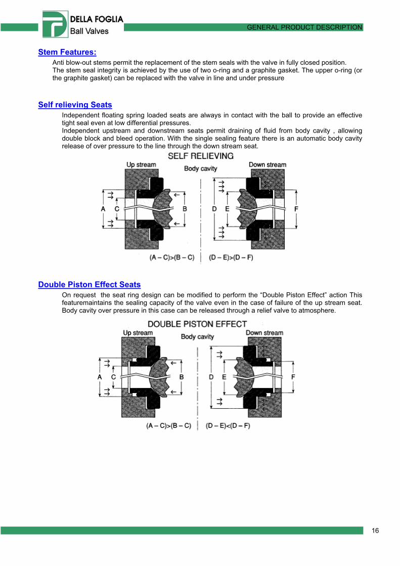
Self relieving Seats Independent floating spring loaded seats are always in contact with the ball to provide an effective tight seal even at low differential pressures. Independent upstream and downstream seats permit draining of fluid from body cavity , allowing double block and bleed operation. With the single sealing feature there is an automatic body cavity release of over pressure to the line through the down stream seat.
Double Piston Effect Seats On request the seat ring design can be modified to perform the “Double Piston Effect” action This featuremaintains the sealing capacity of the valve even in the case of failure of the up stream seat. Body cavity over pressure in this case can be released through a relief valve to atmosphere.

GENERAL PRODUCT DESCRIPTION
17
Double Barrier on body joints A system of double barrier (O-ring and PTFE/graphite seals) is provided in order to prevent all possible leakages.
Emergency Sealant Grease Injection Each valve has a port for sealant grease emergency injection in the stem seals area and an option for an emergency sealant grease injection in the seat seals area . This feature provides a means for emergency seal of a damaged sealing surface using sealant Injection sealant in the upstream seat fitting will provide complete sealing inmost downstream leakage situations Injection sealant in stem zone will provide complete sealing in stem leakage situations.
Emergency Sealant Grease Injection Fitting The sealant grease emergency injection in the seat seals area is assured by a Grease fitting plus a safety check valve .
Standard Grease Fitting Grease Fitting with thread
protected by double o-rings
GENERAL PRODUCT DESCRIPTION
18
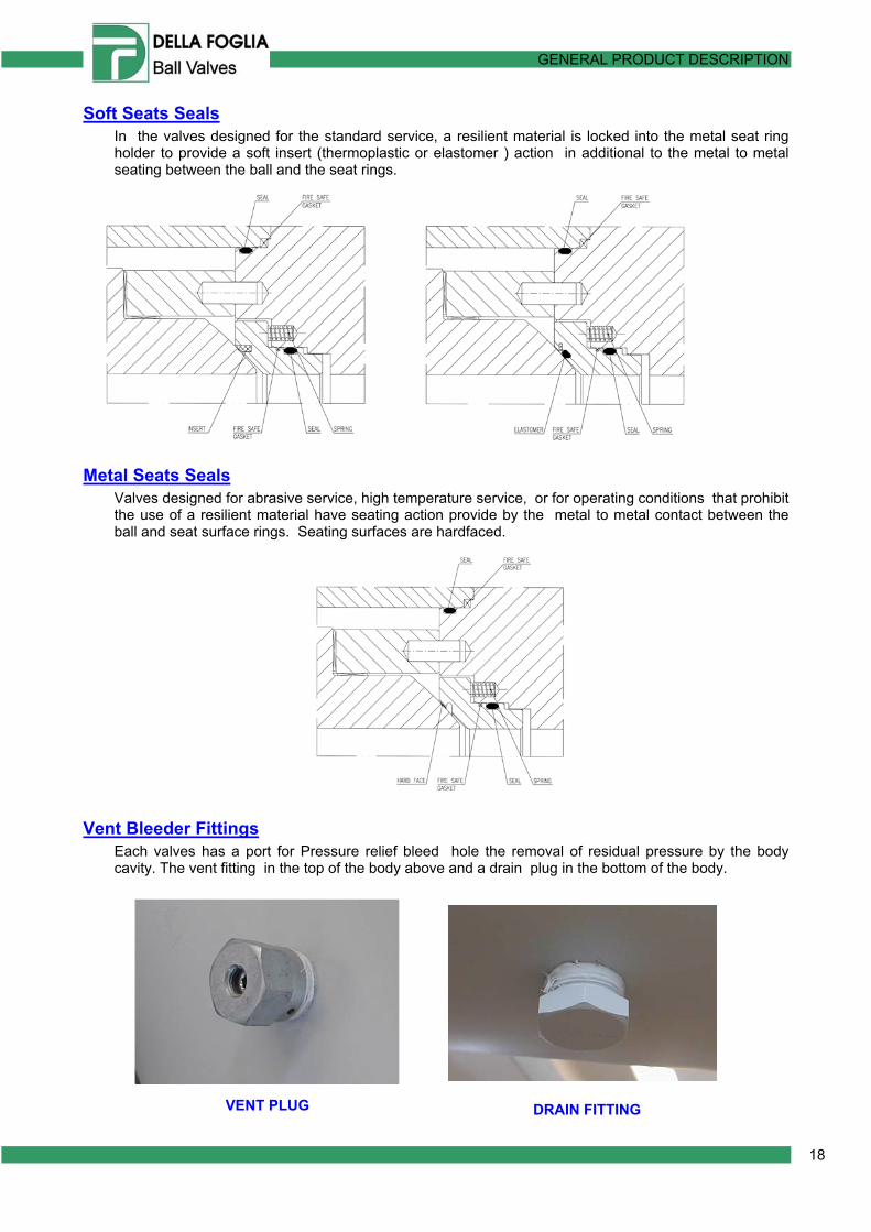
Soft Seats Seals In the valves designed for the standard service, a resilient material is locked into the metal seat ring holder to provide a soft insert (thermoplastic or elastomer ) action in additional to the metal to metal seating between the ball and the seat rings.
Metal Seats Seals Valves designed for abrasive service, high temperature service, or for operating conditions that prohibit the use of a resilient material have seating action provide by the metal to metal contact between the ball and seat surface rings. Seating surfaces are hardfaced.
Vent Bleeder Fittings Each valves has a port for Pressure relief bleed hole the removal of residual pressure by the body cavity. The vent fitting in the top of the body above and a drain plug in the bottom of the body.
VENT PLUG DRAIN FITTING

GENERAL PRODUCT DESCRIPTION
19
Double Block And Bleed
The Double Block and Bleed (DBB) is a standard feature . Whether in the “Open” or “Closed” position, pressure on each side of the ball is blocked from the body cavity by the seat ring. Block and bleed operation is applied in order to:
− Verify integrity of both seats − Allow draining and/or flushing of the valve body cavity − Absolute prevention of downstream leakage to assure safety of downstream activities − When Required: Stem disassembly, with valve in line.
Extended Stem
When ball valves are to be installed below ground on buried pipelines or where not easily accessible, operators can be remote mounted by means of suitable stem extension. Drain Lines and grease injectors (if required) will be piped up to the top of the extension for an easier access. The distance between valve centre and operator hand-wheel must be specified.
Extended stem can also be employed on, valves that have to be installed on a thermal insulated line.

GENERAL PRODUCT DESCRIPTION
20
Extended Bonnet For Low Temperature & Cryogenic Service
Ball Valves to be used in low temperature/cryogenic service are equipped with extended bonnet to allow vapour space between body cavity and stem seals. This feature preserves stem seals from damages that may occur during operations at cryogenic temperatures, and allows stem seal servicing even on valves installed on insulated lines. Vapour space length or insulating thickness shall be specified.
M.V.S. ( Minimum Vapour Space Length ) = The distance between the bottom of the stuffing box and the top of the body stem bearing for rotary valves . Extended bonnets are recommended for :
− continuous low temperature service between minus 50ºC and minus 196 ºC . − “operable valves” in low temperature service between minus 20 ºC and minus 50ºC.
Extended bonnets are not recommended for :
− occasional low temperature service (e.g. during de-pressuring) with a lower design temperature between zero ºC and minus 50 ºC,
− “non-operable” valves in low temperature service between minus 20 ºC and minus 50ºC. − continuous low temperature service between zero ºC and minus 20 ºC.
At low temperature, standard seal and o-ring cease to function properly. Special elastomers are applied at this temperature. Generally they require a special loading to achieve a tight seal, so Lip-seal are employed.
Note: Valves in liquid service, used at sub zero temperatures shall be capable of operation with the valve stem at or above 30 degrees above the vertical position.
Extendend Bonnet Valve for cryogenic service

GENERAL PRODUCT DESCRIPTION
21
Della Foglia, on request, executes also low temperature/cryogenic test on ball valves
High Temperature Service Ball valves for high temperature service are designed with the temperature conditions in mind. At elevate temperatures standard materials are inadequate. Plastics, elastomers, and standard gaskets generally prove unsuitable and must be replaced by more durable materials. Metal-to-metal seating materials and graphite gaskets are necessary. Special top construction is employed to allow load adjustment on graphite seals .
Fire Safe Each valve has a design that is capable of passing a fire test with specified limits on leakage to the atmosphere and downstream after being closed subsequent to fire exposure, according to applicable standards(BS 6755 Part.2, API 6FA and API 607). Fire safe test have been witnessed and certified by customer’s inspectors and independent authorities.

GENERAL PRODUCT DESCRIPTION
22
Low Fugitive Emission Accurate machining of the stem surface and bonnet sealing ensures compliance with the most severe pollution control regulations . The “Low fugitive emission” at ambient and low temperature is assured and tested (when requested). As for this purpose, Della Foglia sas use a Helium Leak Detector (Mass spectrometer)
Abrasive Service Valve intended for use with abrasive fluid, can be provided by special features in order to provide maximum operating lifetime without maintenance intervention. Metal to metal seat seals are necessary, and generally graphite gasket are employed. Most critical internal parts of the valve could be coated with special tungsten carbide alloy (or other coating, when requested).
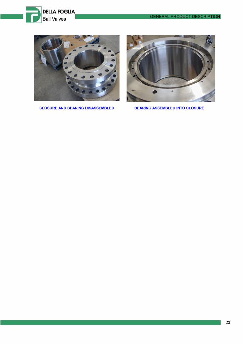
Line Protection Bearings
When Valves have to operate with extremely corrosive / abrasive Fluids a Special Line protection Bearing can be installed in the internal part of the closure This special feature allows to manufacture the part in contact with fluid in special materials, to employ and less expensive material for other parts An accurate machining of the component assure the same performances of conventional valves.
GENERAL PRODUCT DESCRIPTION
23
CLOSURE AND BEARING DISASSEMBLED BEARING ASSEMBLED INTO CLOSURE

GENERAL PRODUCT DESCRIPTION
24
44 TTOOPP EENNTTRRYY BBAALLLL VVAALLVVEESS Top Entry are trunnion mounted ball Valves, in which Ball is inserted into de body trough a hole in the upper zone. Main Feature of Top Entry Ball Valves are the same of side entry trunnion ball valves. − Top entry Bal Valves can be easily serviced without removing the valve from the line. − Stem could be disassembled when valve is under pressure (when requested).
GENERAL PRODUCT DESCRIPTION
25
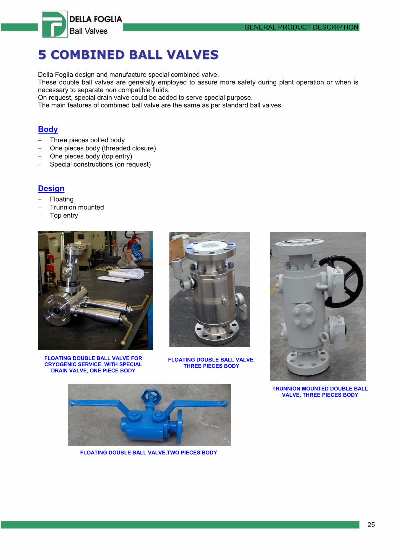
55 CCOOMMBBIINNEEDD BBAALLLL VVAALLVVEESS Della Foglia design and manufacture special combined valve. These double ball valves are generally employed to assure more safety during plant operation or when is necessary to separate non compatible fluids. On request, special drain valve could be added to serve special purpose. The main features of combined ball valve are the same as per standard ball valves.
Body − Three pieces bolted body − One pieces body (threaded closure) − One pieces body (top entry) − Special constructions (on request)
Design − Floating − Trunnion mounted − Top entry
TRUNNION MOUNTED DOUBLE BALL VALVE, THREE PIECES BODY
FLOATING DOUBLE BALL VALVE FOR CRYOGENIC SERVICE, WITH SPECIAL
DRAIN VALVE, ONE PIECE BODY
FLOATING DOUBLE BALL VALVE, THREE PIECES BODY
FLOATING DOUBLE BALL VALVE,TWO PIECES BODY
GENERAL PRODUCT DESCRIPTION
26
66 MMAATTEERRIIAALLSS Carbon Steel 5 ASTM A105 6 ASTM A350 LF2 / Cl. 1 and Cl.2 Low Alloy Steel
• API6A-60K • ASTM A694 F52 (-46°C KV 20/27J) • ASTM A694 F60 (-46°C KV 20/27J) • ASTM A350 LF3 • ASTM A29 Gr.4130 (-46°C KV 20/27J) • ASTM A29 Gr.4140 (-46°C KV 20/27J)
Martensitic Stainless Steel
• ASTM A182 F6a Cl.1 • ASTM A182 F6a Cl.2 • ASTM A182 F6NM
Austenitic Stainless Steel
• ASTM A182 F304/F304L • ASTM A182 F316/F316L • ASTM A182 F316LN Mod. • ASTM A182 F321 • ASTM A182 FXM19 • ASTM A182 F44 (6%Mo)
Age-Hardening S.S.
• ASTM A564 Gr.630 H1050 • ASTM A564 Gr.630 H1150M
Ferritic-Austenitic S.S.
• ASTM A182 F51 - UNS S31803 (DUPLEX S.S.) • ASTM A182 F53 - UNS S32750 (SUPER DUPLEX S.S.) • ASTM A182 F55 - UNS S32760 (SUPER DUPLEX S.S.)
Nickel Alloy
• INCONEL 625 (UNS N06625) • INCOLOY 825 (UNS N8825) • INCONEL X 750 (UNS N07750) • INCONEL 718 (UNS N07718) • MONEL K-400 (UNS N 04400) • MONEL K-500 (UNS N 05500)
GENERAL PRODUCT DESCRIPTION
27
Other materials: • Titanium Gr.2 • Titanium Gr.5 • Titanium Gr.12 • Hastelloy C276 • Alloy 28 • ASTM B148
Bolts Nuts
• ASTM A193 B7 A194 Gr.2H • ASTM A193 B7M A194 Gr.2HM • ASTM A320 L7 A194 Gr.7 or Gr.4 • ASTM A320 L7M A194 Gr.7M • ASTM A320 L43 A194 Gr.7M • ASTM A193 B8 Cl.2 A194 Gr.8 • ASTM A193 B8M Cl.2 A194 Gr.8M • ASTM A453 Gr.660 Cl.a A453 Gr.660 Cl.a • ASTM UNS S31803 UNS S31803 (DUPLEX S.S.) • Titanium Titanium
Seals ELASTOMERIC : 7 NITRIL RUBBER (NBR) 8 HYDROGENATED NITRIL RUBBER (HNBR) 9 VITON A 10 VITON B 11 VITON GLT
(Anti Explosive Decompression for class 900# and larger or by agreements) THERMOPLASTIC
• PTFE • Reinforced PTFE • PCTFE • NYLON 12-G (Lauramid) • NYLON ® SMX • PEEK ® • VESPEL ®
OTHERS :
• GRAPHITE ** • Spiral Wound 316L/GRAPHITE** • LIP-SEALS (PTFE or PEEK ENERGIZED) ** (with corrosion inhibitor)

GENERAL PRODUCT DESCRIPTION
28
77 VVAALLVVEE DDAATTAA SSHHEEEETT Minimum requirements for Ball Valves

GENERAL PRODUCT DESCRIPTION
29
88 GGLLOOSSSSAARRYY For the purposes of this International Standard, the following terms and definitions apply. Acceptance criteria Defined limits placed on characteristics of materials, products or services accessible wetted surface Wetted surface which can be viewed, for purposes of non-destructive examination, by direct line of sight NOTE This excludes test ports, control line ports, lockdown screw holes and other penetrations of these types. Actuator Device used to operate a valve using electric, pneumatic or hydraulic means. Often used for remote control or sequencing of valve operations. Ambient temperature The prevailing temperature of the environment immediately surrounding an object - generally considered to be –20° F to +100° F. ANSI rating class Numerical pressure design class defined in ASME B16.5 and used for reference purpose . Note : The ANSI rating class is designated by the word "Class" followed by a number . Austenitic stainless steel The common stainless steel, where the primary microstructure is austenite and the composition primarily iron but also includes both chromium and nickel. The steels are designated as 300 series such as 304, 316, CF8M, etc. Bevel gear operator Device facilitating operation of a gate or globe valve by means of a set of bevel gears having the axis of the pinion gear at right angles to that of the larger ring gear. The reduction ratio of this gear set determines the multiplication of torque achieved. Back seat A shoulder on the stem of a gate or globe valve which seals against a mating surface inside the bonnet to prevent leakage of media through the bonnet stuffing box when the valve is fully opened. Ball The closure element of a ball valve. Ball valve A valve using a spherical closure element which is rotated through 90 to open and close the valve. Bi-directional valve Valve designed for blocking the fluid in both downstream and upstream directions . Bleed Drain or Vent Block valve Gate, Plug or Ball valve that blocks flow into the downstream conduit when in the closed position . Note : Valves are either single or double-seated, bi-directional or uni-directional . Body The principle pressure containing part of a valve in which the closure element and seats are located. Bolted bonnet A bonnet which is connected to a valve body with bolts or studs and nuts. Bolted construction Describes a valve construction in which the pressure shell elements (such as body and closures of a trunnion ball valve) are bolted together and so can be taken apart and repaired in the field. Bonnet The top part of a valve, attached to the body, which contains the packing gland, guides the stem, and adapts to extensions or operators.

GENERAL PRODUCT DESCRIPTION
30
Bore (or port) The inside diameter of the smallest opening through a valve, e.g., inside diameter of a seat ring, diameter of hole through ball in a ball valve. Breakaway thrust / torque Thrust or torque required for opening a valve with maximum pressure differential . Butt weld end The end connection of a valve suitably prepared for butt welding to a connecting pipe. Carbon steel Iron containing carbon in the form of carbides, about 0.1 to 0.3 percent carbon with no other alloying elements other than the sulphur, phosphorus, and other elements present in almost all steels. Casting A product or the act of producing a product made by pouring molten metal into a mould and allowing it to solidify, thus taking the shape of the mould. Check valve A one-directional valve which is opened by the fluid flow in one direction and closed automatically when the flow stops or is reversed. Closure The ends of a bolted construction ball valve, bolted to the body, which often contain the seat rings. Closure element The moving part of a valve, positioned in the flow stream, which controls the flow through the valve, e.g., wedge, plug, clapper, ball. corrosion-resistant alloy (CRA) Nonferrous-based alloy in which any one or the sum of the specified amount of the elements titanium, nickel, cobalt, chromium, and molybdenum exceeds 50 % (mass fraction) Closure element The moving part of a valve, positioned in the flow stream, which controls the flow through the valve, e.g., wedge, plug, clapper, ball. Cv Flow coefficient expressed as the number of gallons of water that would flow through an opening, such as a valve port, in 1 minute under a differential pressure of 1 psi. CWP Cold working pressure - the maximum allowable pressure under non-shock conditions at ambient temperature ( -20° F to +100° F). Double block and bleed The capability of a valve under pressure to obtain a seal across both the upstream and downstream seat rings and to have its body cavity bled down to atmospheric pressure. Drain plug A fitting at the bottom of a valve, the removal of which permits draining and flushing the body cavity. Drain train All parts of the valve drive between the operator and obturator, including the obturator but excluding the operator . Elastomer A natural or synthetic elastic material, often used for o-ring seals. Typical materials are viton, buna-n, EPDM (ethylene propylene dimonomer), etc. Emergency seat seal A fitting on the valve body through which sealant can be injected to effect a seat seal in an emergency situation. End connection The type of connection supplied on the ends of a valve which allows it to be connected to piping - may be weld end, flanged end, threaded or socketweld. Face to face The overall dimension from the inlet face of a valve to the outlet face of a valve (one end to another) allowing valves of the same size and pressure class to be mutually interchangeable, regardless of manufacturer. Facing The finish of the gasket contact surface of a flange.

GENERAL PRODUCT DESCRIPTION
31
Fitting Any component, other than valves, used with pipe as part of the pressure system and normally referring to items covered by a national standard. Flat Face (FF) A flange surface in which the gasket sealing area is the entire surface from the ID to the outside edge. Usually used for class 125 cast iron valves. Fire safe A valve design that is capable of passing a fire test with specified limits on leakage to the atmosphere and downstream after being closed subsequent to fire exposure. Floating ball A ball valve design in which the ball is not rigidly held on its rotational axis and so is free to float between the seat rings. Flow coefficient (K V) volumetric flow rate, in cubic meter per hour, of water at temperature between 5°C (40°F) and 40°C (104°F) passing through a valve and resulting in a pressure loss of 1 bar (14,7 psi) . Note : KV relates to the flow coefficient CV in US gallons per minute at 15,6°C (60°F) resulting in a 1 psi pressure drop as follow : KV = CV / 1,156 Forging A metalworking process that involves hammering or squeezing, with or without a die, at hot working temperatures to form a specific shape. Full bore (full opening) Describes a valve in which the bore (port) is nominally equal to the bore of the connecting pipe. Full penetration weld Describes the type of weld wherein the weld metal extends through the complete thickness of the parts being joined. Gasket A component whose purpose is to seal a joint between two larger components, softer than the surfaces of the joint being sealed and usually squeezed by means of bolting to effect the seal. Gland or gland bushing The part of the valve which retains or compresses the stem packing in a stuffing box. Gland follower or gland flange The component used to hold down or retain the gland in the stuffing box. Graphite Flexible carbon material used to make gaskets and packing. The gaskets may be flat graphite sheet or have metal inserts for added strength. The packing is a combination of lattice braided rings used as anti-extrusion or wiper rings and die-formed rings which are compressed to effect the seal. Grease fitting A device which permits injection of grease into a bearing surface. Handwheel A wheel-shaped valve operating device intended to be grasped with one or both hands which allows turning the valve stem or operator shaft to which it is attached. Hardfacing A surface preparation in which an alloy is deposited on a metal surface usually by weld overlay to increase resistance to abrasion and or corrosion. Heat analysis A chemical analysis conducted by a foundry immediately prior to pouring which measures the exact chemical composition of a particular batch of molten metal. Heat treatment Describes any process or procedure by which the internal structure of steel is altered by heating to produce desired physical and mechanical characteristics. Hydrostatic test A pressure test in which a valve is tested with water to detect leaks - may be a shell test or a seat closure test. Lever An operating device for quarter-turn valves.
GENERAL PRODUCT DESCRIPTION
32
Dye Liquid inspection A nondestructive method of detecting the presence of surface cracks and imperfections through use of a special red dye. Abbreviated as LPI or PT. Locking device Any valve attachment whose purpose is to prevent the operation of the valve by unauthorized persons. Magnetic particle inspection A non-destructive method of detecting the presence of surface cracks and imperfections through use of fine iron particles in an electrical field. Abbreviated as MPI or MT. Manual actuator /operator wrench (lever) or handwheel or without a gear . Material Test Reports Certificates provided by the steel manufacturer indicating the chemical analysis and mechanical properties of a specific batch of steel traced by sequentially assigned heat numbers or codes. Maximum pressure differential (MDP) maximum difference between the upstream and downstream across the oturator at which the obturator may be operated Nominal pipe size (NPS) numerical metric designation of size which common to components in piping system of any one size . Note : The nominal pipe size is designated by letter DN followed by a number . O-ring An elastomeric or synthetic seal ring of circular cross section. Obturator/ closure member part of a valve, such as a ball, clapper, disc, gate or plug, wich is positioned in the flow stream to permit or block flow . Operator device (or assembly) for opening or closing a valve . Packing The deformable sealing material inserted into a valve stuffing box which when compressed by the gland provides a tight seal about the stem. Pinhole Numerous small gas holes at the surface or just below the surface of castings, generally occurring in the thicker parts of the casting as a reduction in the solubility of gases in the metal as the metal cools. Plastics A broad classification covering a variety of non-metallic, synthetic or organic materials capable of being moulded or formed into desired shapes. Typical materials include nylons and tetrafluoroethylenes such as DuPont’s Teflon . PMI Positive material identification - a method for cross checking the identity of a piece of material, often using a portable spectrometer, usually with x-rays (TN 9266, nuclear analyzer) or a welding arc (Arc Met 900, optical spectrometer). Pneumatic test A test in which a valve is tested with air - usually a seat closure test. Porosity A defect found in castings or welds consisting of gas bubbles or voids in the solidified metal. Position indicator Any external device which visually indicates the open and closed position of valve. Powered actuator/operator electric, hydraulic or pneumatic device bolted or otherwise attached to the valve for powered opening and closing of the valve . Note : The nominal pipe size is designated by letter DN followed by a number Pressure-Temperature Ratings The maximum allowable working pressures at specified temperatures. For steel valves, the ratings are defined by "classes" and found in ASME B16.34. For iron and bronze valves, the ratings are defined in the applicable MSS specifications. Pressure-containing parts parts, such as bodies, bonnets, gland, stem, gasket and bolting, designed to containing the pipeline fluid . Pressure-controlling parts parts, such as seats and obturator, intended to block or permit the flow of fluid.

GENERAL PRODUCT DESCRIPTION
33
Process-wetted part parts exposed directly to pipeline fluid . Product Analysis The chemical analysis of a material done on a finished component to show compliance with the material specifications. Usually has tolerances defined for each element to allow for differences in the completed product compared to the molten metal. PSI Pounds per square inch - the force per unit area exerted against a resisting body. Ra Abbreviation for "arithmetic average roughness height" - the measure of the roughness of a surface expressed in microinches. The higher the number, the rougher the surface. Used to designated the desired surface finish for end flange raised faces. Radiographic inspection A non-destructive inspection method using x-rays to locate internal flaws in castings, fabricated parts and welds. Abbreviated as RT. Raised faced (RF) The raised area of a flange face which is the gasket sealing surface between mating flanges. Defined in ASME B16.5. Class 150 and 300 valves have 0.06" RF and Classes 600 and up have a 0.25" RF. Reduced port A valve port opening that is smaller than the line size or the valve end connection size. Ring type joint (RTJ) A flange connection using a specially shaped soft metal ring as a gasket. Generally used on high pressure valves. May be the body and bonnet connection and/or the end flange connection. Resilient seat A valve seat containing a soft seal such as an o-ring or plastic to assure tight shut-off. Rim pull The force required at the edge of the handwheel to generate the required torque at the center of the handwheel. Seal weld A weld that does not contribute anything to the mechanical integrity of an assembly, but is made purely to seal or prevent leakage from, for instance, a threaded joint. Seat The part of a valve against which the closure element effects a tight shut-off. Seating surface contact surface of obturator and seat which ensure valve sealing . Self-relieving The process by which excessive internal body cavity pressure is automatically relieved either into the upstream or downstream line - generally found in ball valves Shrinkage Internal defect in castings that are internal voids, irregular in shape, caused by volume contraction during solidification. Can be caused by not maintaining a fluid channel to the riser during solidification. Sour gas Natural gas containing significant amounts of hydrogen sulfide (H2S). Requires special material treatments to avoid valve failures from sulfide corrosion cracking. Specification A document that defines the requirements that a finished product must conform to - may include chemical and mechanical properties, tolerances, marking, shipping, etc. Stainless steel Any of a number of types of iron alloy with chrome, nickel, or other elements that does not oxidize in free air. Stem The rod or shaft transmitting motion from an operator (handwheel or gear operator) to the closure element of the valve.
Stem extension assembly assembly consisting of the stem extension and the stem extension housing . Stud A bolt, threaded on both ends, often used in bolting together bodies and bonnets or bodies and closures.
GENERAL PRODUCT DESCRIPTION
34
Stuffing box The annular chamber provided around a valve stem in a sealing system into which deformable packing is placed. Sometimes called packing chamber. Support ribs or legs metal structure which provided a stable footing when the valve is set a fixed base . Tensile strength The highest tensile stress that a material can withstand before failure or rupture occurs - the force being applied in a direction tending to elongate the material. Tensile test A destructive test performed on a specially machined specimen taken from material in its delivered condition to determine mechanical properties, such as tensile strength, yield strength, and percent elongation.. Throttling The intentional restriction of flow by partially closing or opening a valve. Through-conduit valve valve with an unobstructed and continuous cylindrical opening Thrust The net force applied to a part in a particular direction - e.g., on the end of a valve stem Torque The rotational force imposed on or through a shaft, usually expressed in foot-pounds. Trunnion The part of a ball valve which holds the ball on a fixed vertical axis and about which the ball turns. Turns to operate The number of complete revolutions of a handwheel or the pinion shaft of a gear operator required to stroke a valve from fully open to fully closed or vice versa. Twin-seat, both seat bi-directional, valve valve with two seats, each sealing in both directions .
Twin-seat, one seat uni-directional and one seat bi-directional, valve valve with two seats, one sealing in one direction and other in either direction . Ultrasonic inspection An inspection procedure using high frequency sound waves to detect wall thickness or flaws throughout the thickness of metal parts. Abbreviated as UT. Uni-directional valve valve designed for blocking the flow in one direction only . Union bonnet A type of valve construction in which the bonnet is held on by a union nut with threads on the body. Valve A device used to control the flow of fluid contained in a pipe line. Venturi plug valve valve with a substantially reduced opening through the plug and a smooth transistion from each full-opening and to the reduced opening . Working pressure The pressure (pounds per square inch) at which a valve is designed to operate. Wall thickness The thickness of the wall of the pressure vessel or valve. For steel valves, minimum thickness requirements are defined in ASME B16.34, API 600, and API 602. Yield strength The limiting stress beyond which a material will sustain permanent deformation.

GENERAL PRODUCT DESCRIPTION
35
99 SSYYMMBBOOLLSS AANNDD AABBBBRREEVVIIAATTIIOONNSS
9.1 Symbols
CV Flow coefficient in imperial units KV Flow coefficient in metric units
9.2 Abbreviations
BE Bevelled end BM Base metal BW Butt weld CE Carbon equivalent CJ Compact flange end DBB Double-block and Bleed CL Clamped type end DN Nominal size CR Compession fitting end HAZ Heat-affect zone EDS Element Data Sheet HR Rockwell hardness FB Full bore HV Vickers hardness FF Flat face MPD Maximum pressure differential [∆p] FL SAE Flanged SAE MT Magnetic Particle testing FS Female Sub NDE Non-destructive examination FT Female threaded end NPS Nominal Pipe Size Galv Galvanized PN Nominal pressure LR Long radius elbow PQR Procedure qualification record MDS Material Data Sheet PT Penetrant testing MS Male Sub PWHT Post-weld heat treatment MT Male threaded end SMYS Specified Minimum Yeld Strengh PCS Piping Class Sheet WM Weld metal PE Plain end WPS Weld procedure specification RB Reduced bore WQR Welder qualification record YS Yield stress Wt Wall thickness
RF Raised face CGF Compressed glassfibre gasket
Rm Ultimate tensile stress GRE Glassfibre reinforced epoxy RJ Ring Type Joint GRVE Glassfibre reinforced vinylesterRTJ Ring Type Joint VDS Valve Data Sheet SC Service code WN Welding neck SCH Schedule VSK Valve Specification Key Smls Seamless VSM Valve Selection Manual Sst Stainless steel TE Threaded end DB&B Double Block and Bleed DPE Double Piston Effect

GENERAL PRODUCT DESCRIPTION
36
1100 SSTTAANNDDAARRDD AANNDD CCOODDEESS
API American Petroleum Institute
API 6D* Specification for Pipeline Valves API 6A Specification for Wellhead and Christmas Tree Equipment API 6FA Specification for Fire Test for Valves API 591 User Acceptance of Refinery Valves API 598 Valve Inspection and Testing API 607 Fire Test for Soft-Seated Quarter Turn Valves API 17D Specification for Subsea Wellhead and Christmas Tree Equipment API 5L Specification for Line Pipe
* API 6D/ISO14313
ANSI American National Standards Institute
ASME American Society of Mechanical Engineers
ASME - ANSI Standards B16.34 Valves Flanged, Threaded, and Butt-welded End B16.5 Pipe Flanges and Flanged Fittings B16.10 Face-to-Face and End-to-End Dimensions of Valves B16.11 Forged Fittings, Socket Welding and Threaded B16.20 Ring-Joint Gaskets and Grooves for Steel Pipe Flanges B16.25 Butt-welded Ends B16.47 Large Diameter Steel Flanges B1.1 Unified Inch Screw Threads B18.2.1 Square and Hex Bolts and Screws B18.2.2 Square and Hex Nuts B31.1 Power Piping B31.3 Chemical Plant and Petroleum Refinery Piping B31.4 Liquid Petroleum Transportation Piping Systems B31.8 Gas Transmission and Distribution Piping Systems ASME Boiler and Pressure Vessel Code Section II Materials Section III Rules for Construction of Nuclear Power Plant Components Section V Non destructive Examination Section VIII Rules for Construction of Pressure Vessels Section IX Welding and Brazing Qualifications Section XI Rules for In service Inspection of Nuclear Power Plant Components
GENERAL PRODUCT DESCRIPTION
37
ASTM American Society for Testing and Materials
Volume 01.01 Steel Piping, Tubing, Fittings Volume 01.02 Ferrous Castings Volume 01.03 Steel Plate, Sheet, Strip, Wipe Volume 01.04 Steel Structural Reinforcing, Pressure Vessel, Railway Volume 01.05 Steel Bars, Forgings, Bearing, Chain, Springs Volume 02.01 Copper and Copper Alloy Volume 02.04 Non ferrous Metal, Nickel, Lead, Tin, Zinc, Cadmium and Alloys A 105 Forgings, Carbon Steel, for Piping Components A 182 Forged or Rolled Alloy - Steel Pipe Flanges, Forged Fittings, and Valves
and Parts for High Temperature Service A 216 Carbon Steel Castings Suitable for Fusion Welding for High-
Temperature Service A 217 Martensitic Stainless Steel and Alloy Steel Castings for Pressure
Containing Parts Suitable for High Temperature Service A 350 Forgings, Carbon and Low-Alloy Steel, requiring Notch Toughness
Testing for Piping Components A 351 Austenitic Steel Castings for High Temperature Service A 352 Ferritic Steel Castings for Pressure Containing Parts Suitable for Low
Temperature Service A 370 Mechanical Testing of Steel Products A694 Carbon and Alloy Steel Forgings for Pipe Flanges, Fittings, Valves, and
Parts for High-Pressure Transmission Service . A479 Stainless Steel Bars and Shapes for Use in Boilers and Other Pressure
Vessels . A564 Hot-Rolled and Cold-Finished Age-Hardening Stainless Steel Bars and
Shapes . A193 Alloy-Steel and Stainless Steel Bolting Materials for High-Temperature
Service . A320 Alloy-Steel and Stainless Steel Bolting Materials for Low-Temperature
Service . A194 Carbon and Alloy Steel Nuts for Bolts for High Pressure or High
Temperature Service or Both . A453 High-Temperature Bolting Materials, with Expansion Coefficients
Comparable to Austenitic Stainless Steels . A106 Seamless Carbon Steel Pipe for High-Temperature Service . A333 Seamless and Welded Carbon Steel Pipe for Low-Temperature Service
. A312 Seamless and Welded Austenitic Stainless Steel Pipes .
GENERAL PRODUCT DESCRIPTION
38
NACE National Association of Corrosion Engineers
MR 0175 Standard Material Requirements Sulfide Stress Cracking Resistant
Metallic Material for Oilfield Equipment
BSI British Standards Institution
BS 5351 Steel Ball Valves BS 6364 Valves for Cryogenic Service BS 6755 Testing of Valves BS 6755 Testing of valves - Part 2. Specification for fire type testing
requirements
MSS Manufacturers Standardization Society of the Valve and Fitting Industry
MSS SP-6 Standard Finishes for Contact Faces of Pipe Flanges and connecting
ends Flanges of Valves and Fittings MSS SP-25 Standard Marking System for Valves, Fittings, Flanges and Unions MSS SP 45 By-pass and Drain Connections MSS SP-55 Quality Standard for Steel Castings (visual method) MSS SP-72 Ball Valves with Flanged or Butt-Welding Ends for General Service
EN 10204 Metallic products – Type of inspection documents 97/23/EC Pressure Equipment Directive 94/9/EC Equipment intended for use in potentially explosive atmospheres