general recommendations for the use of … · general recommendations for the use of ... parameters...
TRANSCRIPT

General recommendations
for the use of geomembranes in
barrier systems
2017 EDITION

2 Recommendations for the use of geomembranes in barrier systems
General recommendations for the
use of geomembranes
in barrier systems
2017 Edition
1. Presentation of document ......................................................................................................................... 7
1.1. Objectives of document .................................................................................................................... 7
1.2. How to use this document ................................................................................................................ 7
1.3. Targeted domains of application ...................................................................................................... 7
1.4. Organization of document ................................................................................................................ 8
2. Presentation of lining systems ................................................................................................................... 9
2.1. Generalities ....................................................................................................................................... 9
2.2. Definitions associated with lining systems ........................................................................................ 9
2.3. Support structure ............................................................................................................................11
2.3.1. Functions .................................................................................................................................11
2.3.2. Sub-base materials ..................................................................................................................11
2.3.3. Materials for support layer .....................................................................................................11
2.3.4. Networks for drainage ............................................................................................................12
2.4. Sealing structure: the geomembrane(s) .........................................................................................13
2.4.1. Definition of a geomembrane .................................................................................................13
2.4.2. On-site function of geomembranes ........................................................................................14
2.4.3. The major families of materials ..............................................................................................14
2.4.4. The main sectors of geomembrane production .....................................................................15
2.4.5. Characteristics and behavior of geomembranes ....................................................................15
2.5. Protective layer ...............................................................................................................................16
2.5.1. Functions .................................................................................................................................16
2.5.2. Materials .................................................................................................................................16
2.6. Examples of several possible lining system configurations .............................................................17
3. Design ......................................................................................................................................................18
3.1. General points .................................................................................................................................18
3.2. Parameters to consider in designing the facility .............................................................................19
3.2.1. Consequences classes .............................................................................................................19
3.2.2. Geometrical considerations ....................................................................................................19
3.2.3. Climatic considerations ...........................................................................................................21
3.2.4. Impact of fluids adjacent to the facility ..................................................................................22
3.2.5. Considerations related to diverse mechanisms of damage ....................................................22
3.2.6. Geotechnical considerations ...................................................................................................23
3.2.7. Test zones ...............................................................................................................................24

3 Recommendations for the use of geomembranes in barrier systems
3.3. Parameters to consider for operation of facility .............................................................................24
3.3.1. Considerations related to security and maintenance .............................................................24
3.3.2. Considerations related to durability .......................................................................................24
3.3.3. Considerations related to various problems ...........................................................................25
3.3.4. Hydraulic considerations .........................................................................................................26
3.3.5. Considerations related to requirements specific to the facility..............................................27
3.4. Technical and regulatory documents concerning elements of the lining system ...........................27
3.4.1. Technical specifications ..........................................................................................................27
3.4.2. Contractual requirements from manufacturer for installing geomembrane .........................27
3.4.3. CE marking ..............................................................................................................................28
3.4.4. Certifications and technical licenses .......................................................................................28
4. Construction of facility ............................................................................................................................30
4.1. Preparation of base form ................................................................................................................30
4.1.1. Compaction .............................................................................................................................30
4.1.2. Removal of vegetation ............................................................................................................31
4.1.3. Treatment of slope crest .........................................................................................................31
4.1.4. Slope of base form ..................................................................................................................31
4.2. Requirements for support structure ...............................................................................................31
4.2.1. Form layer ...............................................................................................................................31
4.2.2. Water drainage .......................................................................................................................32
4.2.3. Gas drainage ...........................................................................................................................33
4.3. Ensuring impermeability .................................................................................................................33
4.3.1. General measures ...................................................................................................................33
4.3.2. Transport and storage .............................................................................................................33
4.3.3. Packaging and marking ...........................................................................................................34
4.3.4. Placing the panels ...................................................................................................................34
4.3.5. Welding of geomembrane panels ...........................................................................................35
4.3.6. Anchoring ................................................................................................................................40
4.3.7. Connection with neighboring works .......................................................................................44
4.3.8. Certifications or qualifications ................................................................................................47
4.4. Installation of protection layer ........................................................................................................48
5. Reception and control of construction ....................................................................................................50
5.1. Domain of control ...........................................................................................................................50
5.2. General recommendations regarding control of a lining system ....................................................50
5.2.1. Control of site organization ....................................................................................................50
5.2.2. Control of areas for storage and product handling ................................................................50
5.2.3. Control of materials and equipment upon reception at site ..................................................51
5.2.4. Test zones and performance tests ..........................................................................................51
5.2.5. Control associated with reception and installation of support structure ...............................52
5.2.6. Control of layout plan .............................................................................................................52
5.2.7. Control of construction-phase plan ........................................................................................52
5.2.8. Control of impermeability .......................................................................................................52
5.2.9. Control methodology ..............................................................................................................54
5.2.10. Controls associated with installation of protective structure .................................................56
5.2.11. Control of as-built file .............................................................................................................56
6. Quality assurance ....................................................................................................................................57
6.1. Terminology for quality assurance ..................................................................................................57

4 Recommendations for the use of geomembranes in barrier systems
6.2. Organization of actions to ensure quality .......................................................................................58
6.3. Content of Quality Assurance Plan ..................................................................................................59
7. Guarantees, insurance, disputes .............................................................................................................61
7.1. Role of the various parties ..............................................................................................................61
7.2. Guarantees ......................................................................................................................................62
7.3. Insurance .........................................................................................................................................62
7.4. Litigation ..........................................................................................................................................62
Appendix A: Glossary .......................................................................................................................................64
Appendix B: Bibliography and normative documents .....................................................................................70
Appendix C: Characteristics and minimal performances for geomembranes .................................................73
Bituminous geomembranes .........................................................................................................................73
High-density polyethylene geomembranes .................................................................................................74
Flexible polypropylene geomembranes ......................................................................................................75
Plasticized polyvinyl chloride geomembranes .............................................................................................76
Ethylene propylene diene monomer geomembranes .................................................................................77
Appendix D: Elements to assist in developing specifications ..........................................................................78

5 Recommendations for the use of geomembranes in barrier systems
List of figures Figure 1 — Composition of a lining system (LS). Figure 2 — Example of a LS. Figure 3 — Example of basin with vegetated upper protection. Figure 4 — Another example of basin with vegetated upper protection. Photo 5 – Implementation of P-PVC welding: double weld, manual weld. Photo 6 – Welding of HDPE: double weld, extrusion. Photo 7 – Welding of bituminous geomembranes. Photo 8 – Welding with EPDM. Figure 9 – Overlaps and multiple assemblies. Figure 10 – Schematic diagram of anchoring trench for exposed geomembrane. Figure 11 – Schematic diagram of anchoring trench for protected geomembrane. Figure 12 – Example of anchorage with top fill as load. Figure 13 – Example of anchorage with concrete border. Figure 14 – Example of anchoring at the foot in the case of a dike. Figure 15 – Section of mechanical fastener based on a metallic straightedge. Figure 16 – Example of seal around concrete mass. Figure 17 – Example of seal around concrete mass. Figure 18 – Example of seal around concrete mass. Figure 19 – Example of seal around piping via sleeve. Figure 20 — Impermeability mechanism for geomembrane.
List of tables Table 1 — Consequences classes. Table 2 — Minimum values for weighting sections. Table 3 — European standards for geosynthetics.
Table 4 — Means required for welding. Table 5 — Width of Overlaps and of assemblies.

6 Recommendations for the use of geomembranes in barrier systems
List of abbreviations and acronyms used in this document
AFAG: Association Française des Applicateurs de Géomembranes (French Association of Geomembrane Installers) ABF: As-built file APP: Atactic polypropylene CC: Consequence class CFG: Comité Français des Géosynthétiques (French Committee of Geosynthetics) Cofrac: Comité français d'accréditation (French Committee of Accreditation) DoP: Declaration of Performance EPDM: Ethylene propylene diene terpolymer FNTP: Fédération Nationale des Travaux Publics (French National Federation of Public Works) F-PP: Flexible polypropylene GCL: Geosynthetic clay liner GDP: General development program LDPE: Low-density polyethylene LS: Lining system OPN: Optimum proctor normal PEHD: High-density polyethylene P-PVC: Plasticized polyvinyl chloride QAP: Quality Assurance Plan QMP: Quality master plan SBS: Styrene-butadiene-styrene SHSP: Specific health and safety plan ODQAP:Organizational diagram of quality assurance plan TPO: Thermoplastic olefin

7 Recommendations for the use of geomembranes in barrier systems
1. Presentation of document
1.1. Objectives of document The objective of this document is to provide general information about lining systems (LSs), and in particular about geomembranes themselves. The goal is to give professionals in this field the necessary elements to assist in the conception, implementation, control, reception, monitoring, and maintenance of the works in question.
1.2. How to use this document This document has not been subject to the French homologation procedure and must in no case be regarded as a French standard. Its use must stem strictly from a voluntary approach on the part of the user. This document is a collection of definitions, information, and recommendations used by professionals in the field, such as project managers, contractors, laboratories, experts, and geosynthetic manufacturers and installers. This document does not discuss geosynthetic clay liners, geofilms less than 1 mm thick, or membranes narrower than 1.5 m, which are not considered as geomembranes by the current applicable standard (NF P84-500).
1.3. Fields of application This document covers the following fields of application:
Hydraulic works (dams, ponds, canals, ditches, …),
Containment structures for solid and liquid materials, and
Roads and railways. This document does not discuss the following types of works:
Bridges and associated works,
Works associated with building construction,
Underground civil engineering works (casings, tunnels, covered trenches, …), and
Landfills, discussed by Fascicle 11 of the Comité Français des Géosynthétiques (CFG; French Committee of Geosynthetics).
Note, however, that, even for LSs of different constitution, elements associated with the installation of geomembranes may be applicable to this type of work.

8 Recommendations for the use of geomembranes in barrier systems
1.4. Structure of this document
This document is divided into the following parts:
Part 1: Presentation of document; Part 2: Presentation of lining systems; Part 3: Design; Part 4: Construction of facility; Part 5: Reception and control of construction; Part 6: Quality assurance; Part 7: Guaranties, insurance, disputes.
These parts are complemented by the four following appendixes:
Appendix A: Glossary; Appendix B: Bibliography and normative documents; Appendix C: Characteristics and minimal performance of geomembranes; Appendix D: Elements to assist in developing specifications.
9 Recommendations for the use of geomembranes in barrier systems
2. Presentation of lining systems
2.1. Generalities A lining system (LS) LS is a structure that:
Is impervious to liquids and gases: o In the continuous sections, o At the seams between continuous sections, o At points where the geomembrane is fixed to the associated infrastructure
(concrete or metal structures, pipes, etc.),
Shall maintain its barrier function under the strains : o Of Installation (for example, dynamic perforation), o in service (for example, perforation, differential settlement, weathering), o of operation (for example, chemical attack from the medium, mechanical
strains related to maintenance of works). The sole function of a geomembrane is to act as a barrier against water or gas. Given the various aforementioned strains, it must be integrated into a multi-structure system, with each structure performing the well-defined function defined in the following section.
2.2. Definitions associated with lining systems The definitions associated with LSs and with geomembranes are given in the standard NF P84-500. Some of these terms are also explained in Appendix A. Figures 1 and 2 show the composition of a LS.

10 Recommendations for the use of geomembranes in barrier systems
Figure 1 — Composition of a lining system (LS).
Figure 2 — Example of a LS.
LINING SYSTEM
PROTECTION LAYER (Optional)
BARRIER
SUPPORT STRUCTURE
Vent
Gas drainage
Géotextile
Géomembrane

11 Recommendations for the use of geomembranes in barrier systems
2.3. Support structure The support structure includes the sub-base and the support layer for the geomembrane with eventual drainages for water and gas and the bottom protection layer. It is installed on the prepared subgrade and underneath the barrier.
2.3.1. Functions
The function of the support structure is to protect the barrier from mechanical injury. The materials from which it is made must themselves be non-puncturable, devoid of vegetation, and chemically compatible with the barrier. The support structure must be independently stable, both during construction and during its service life. During construction, the role of the support structure is to allow or facilitate the installation of the geomembrane. Subsequently, when the site is in use, the structure must distribute the transmitted forces by generating only deformations that are acceptable for the geomembrane (the deformations shall not lead to short- or long-term degradation of the barrier function of the geomembrane). When one or more drainage systems are integrated into the support structure, they must nullify the effects of gas or water pressure from underneath. The drainage of water can, in certain cases, allow the detection and eventual recuperation of accidental infiltrations.
2.3.2. Sub-base materials
Depending on the project and the site location, the sub-base may be composed of a variety of materials (clay, sand-gravel mixture, cement, etc.). The sub-base must be accepted by the contractor, the company responsible for the earthworks or structural system, and by the installer.
2.3.3. Materials for support layer
Depending on the project and the site location, the support layer will consist of a large variety of materials whose function is to protect the geomembrane (geotextiles or related products, sand, etc.). Notwithstanding conflicting instructions from the designer or the contractor, the protection geotextile that constitutes the support layer is laid between the sub-base and the geomembrane. Note: In the particular case of projects in which a clayey support layer is supposed to serve as a passive safety barrier, no drainage material should be installed between the support layer and the geomembrane. In certain cases, the installation of a thin geotextile (serving uniquely for cleanliness) may prove necessary for the realization of the installation and to ensure the proper conditions for the welding of the geomembrane. In this case, the features of the geotextile should be determined by the designer, who can consult the CFG document “Recommendations for protecting geomembranes from puncture,” which is currently under development.

12 Recommendations for the use of geomembranes in barrier systems
2.3.4. Networks for drainage
2.3.4.1. Networks for draining water
The presence of water beneath the barrier can interfere with the proper functioning of the structure (water pressure, thermos-osmosis, condensation, freeze-thaw, erosion, loss of stability of the support or of the embankments, etc.). Notwithstanding conflicting instructions from the designer or the contractor, a network for water drainage must be designed and adapted to the expected volume of water. It should consist in either a granular layer, a drainage geosynthetic or draining trenches. Note: When a clayey support layer serves as a passive safety barrier, no drainage structure should be installed between the clay layer and the geomembrane. The granular layer has a permeability k greater than or equal to 10−5 m/s and a thickness greater than or equal to 0.1 m. In some cases, a sand layer may serve both for drainage and as the support layer. Drainage geosynthetics provide high in-plane flow capacities. The CFG guide “Recommendations for the use of drainage and filter geosynthetics”1 may be used for design purposes. To avoid clogging the drainage system and avoid soil erosion, a filter should be used between the draining layer and the neighboring soil layers while respecting the filter guidelines for granular materials and geotextile design. The drained water is collected by collectors placed at the lowest points of the installation. If significant quantities of water are involved or high flow occurs, a denser network of collectors should be installed. In the desirable case where the drainage system allows the detection and quantification of the drainage flow, it is important to verify that the collected flow at the exit of the drainage network is not increased by water from outside the system. Conversely, the measured flow may be less than the real flow because of leaks into the zone underneath the drainage network. This may be avoided by using double lining systems. For large works, the recommendation is to divide the drainage system into zones. The dimensions of the network required to drain water depends on the following factors:
The water flow coming from outside the system,
The maximum allowable leakage,
The maximum allowable water pressure under the lining system, either due to normal service or due to accidental leaks, and
The permeability of the support soil, which influences the speed at which the underlying water table rises.
Depending on the hydrogeological context, an additional drainage system external to the primary installation may be necessary. To ensure water flow, the drainage network is associated with an outlet. Water is evacuated either by gravity or by pumping.
1 Recommandation pour l’emploi des géosynthétiques de drainage et de filtration

13 Recommendations for the use of geomembranes in barrier systems
2.3.4.2. Network to drain gas
Similarly, a network must be installed to drain the underlying gas, due to the rapid rise of the water table in a non-saturated soil, the decomposition of deeply buried organic material, the leakage of liquid rich in organic matter, the presence of polluted soil, etc. Notwithstanding conflicting instructions from the designer, such a network should be installed systematically and should cover an area at least 20% that of the entire installation area. The gas drainage system should include:
A drainage geosynthetic, and
A separation or filtration system to avoid clogging the drainage system (e.g., filtration geotextile).
If gas drainage is not installed over the entire area, it must be spread at regular intervals over the bottom and sides of the installation. The gas drains exit in the open air at the high points and should be protected (hat and mesh) to prevent obstruction or infiltration of water or foreign objects. The exits and their connections should not allow surface-runoff water to enter. The diameter of the air vents should be at least 75 mm.
2.4. Barrier: the geomembrane(s)
2.4.1. Definition of a geomembrane
Geomembranes are defined in the standard NF P84-500. Geomembranes are characterized as follows. They are:
Thin (thereby excluding sealing products consisting of mortar or of bituminous putties centimeters or decimeters thick),
Thicker than 1 mm (functional thickness greater than or equal to 1mm, thereby excluding geofilms with functional thicknesses less than 1 mm),
Flexible (thereby excluding a layer of cement mortar or a metal sheet),
Watertight: the minimum level of impermeability defined in the standard is 10−5 m3 m−² d−1, and
They may be assembled into continuous sheets via seams that are watertight and that offer good resistance (thereby excluding all products that cannot be thermally or chemically assembled).
Geomembranes are products that are manufactured and transported to the installation site in the form of panels of various widths (starting at 1.5 m) rolled or in sheets (pre-assembled at the factory) with surface areas up to 1000 m2 or more. This use of large width or wide area minimizes the risks associated with welding on site. The manipulation of these products with high surface area and weight (up to several tons per roll) requires special handling and installation procedures adapted to the context of the site (geometry, access, etc.). In addition, the proper material must be used. A geomembrane surface may be more-or-less smooth, or even quite rough. In the latter case we speak of “textured” geomembranes. Geomembranes may be reinforced and/or associated with one or several components (i.e., composite geomembrane). Geosynthetic clay liners (GCLs) are not geomembranes and are thus not discussed in the

14 Recommendations for the use of geomembranes in barrier systems
document. The use of such products is discussed in Fascicle 12 of the CFG2.
2.4.2. On-site function of geomembranes
Geomembranes serve a single purpose: act as a barrier.
2.4.3. The main families of materials
Two major types of geomembranes exist. They are divided into six main chemical families:
Bituminous geomembranes: o Based on oxidized bitumen, o Based on bitumen modified by polymers,
Polymeric geomembranes: o P-PVC (plasticized polyvinylchloride), o HDPE (high-density polypropylene), o F-PP (flexible polypropylene), o EPDM (ethylene propylene diene terpolymer elastomer).
Other types of geomembranes also exist on the French market (LDPE: low-density polyethylene, TPO: thermoplastic olefin, etc.). These are not discussed in the present list of recommendations because they are not clearly defined in the profession. Nevertheless, the principles described herein apply to all chemical families of geomembranes. Bituminous geomembranes The following main bituminous materials are used to manufacture geomembranes:
Oxidized or “air-blown” bitumen obtained by oxidation in the refinery of bitumen from direct distillation, and
Bitumens modified by the addition of polymers (polymerized bitumens). The main polymers used are thermoplastic elastomers such as styrene-butadiene-styrene (SBS) or plastomers such as atactic polypropylene (APP).
Bituminous geomembranes are reinforced by a veil of glass and/or of nonwoven polyester. Polymeric geomembranes The two main families of polymers most used in industry are plastomers and elastomers. Precisely classifying a geomembrane into one of these families is not obvious because chemistry offers innumerable possible mixtures of the base products. This remark thus puts their classification into perspective:
Plastomers (or thermoplastic polymers), amenable to successive softening by heating and hardening by cooling for welding. The main plastomers used in geomembranes are:
o Plasticized polyvinyl chloride (P-PVC); o High-density polyethylene(HDPE); o Flexible polypropylene (F-PP).
Elastomers are polymers that rapidly revert to their initial dimensions once strains are removed. This characteristic is obtained in the factory by vulcanization, which in particular renders the product infusible. The main elastomer used for geomembranes manufacturing is ethylene propylene diene terpolymer (EPDM).
2 Recommandations générales pour la réalisation d’étanchéité par géosynthétiques bentonitiques

15 Recommendations for the use of geomembranes in barrier systems
2.4.4. Main sectors of geomembrane production
Bituminous geomembranes are manufactured by impregnation and coating sheets of glass and/or by reinforcing bituminous material with nonwoven polyester. The vast majority of polymer-based geomembranes are produced in complex, high-output facilities by calendering, casting, extrusion blow molding, or coating.
2.4.5. Characteristics and behavior of geomembranes
Average minimal characteristics of the various families of geomembranes The principle characteristics of various geomembranes are specified by family and by thickness in Appendix C. Behavior of the various families of geomembranes Bituminous geomembranes: reinforced geomembranes, heavy, significantly thick, gas welded, compatible with prefabricated protective asphalt. EPDM: significant elasticity and flexibility, prefabrication of larges sheets, thereby reducing the number of joints on site, welding by cold vulcanization. HDPE: high chemical resistance, fabricated in wide roles to reduce the number of welds in an installation, welding by fusion (double welding) or extrusion. F-PP: compromise between flexibility and chemical resistance, fabricated in wide rolls to reduce the number of welds in an installation, welding by fusion (double welding) or extrusion. P-PVC: flexibility, large choice of colors, possible to prefabricate, welding by fusion (double welding). In each case, the designer must ensure that the project characteristics are compatible with the type of geomembrane. Several geomembranes may be used for a given project.

16 Recommendations for the use of geomembranes in barrier systems
2.5. Protection structure
2.5.1. Functions
The eventual need within the LS of a protection structure above the barrier depends on the capacity of the “support structure–sealing structure” to react, without losing its characteristics, to the various external solicitations imposed on it both during the installation and during the operational period of the facility. Chapter 3 discusses the solicitations that should be considered to determine whether an upper protection structure is necessary and, if so, its design. In certain cases, the protection structure may also play a role in the aesthetics of the facility or in its integration into the surrounding landscape. The choice of cover materials no longer depends solely on technical considerations.
2.5.2. Materials
Commonly used materials to protect geomembranes include natural materials (earth, sand, gravel, riprap, etc.), hydraulic concrete mixed on-site, prefabricated concrete elements (flagstones, interlocking paving stones, etc.), or bituminous materials. The upper protection structure should be self-stable to avoid mechanically soliciting the geomembrane. However, placing materials over the geomembrane exerts forces on the latter, which means that the various components of the LS must be stable against slides. Control of this is done according to the standard XP G38-067 (being revised by prNF G38-067). The result may require putting in place a mechanism to reinforce and hold the terrain as well as to add appropriate anchorings. Notwithstanding justification to the contrary from the designer, we interpose a transition layer (puncture protection geotextile, thin material, etc.) between the geomembrane and the materials of the protection layer, whose function is to ensure mechanical protection against aggressive elements, in particular during their installation.

17 Recommendations for the use of geomembranes in barrier systems
2.6. Examples of several possible lining system configurations
Figure 3 — Example of pond with vegetated upper protection.
Figure 4 – Example of pond with vegetated upper protection.
Geomembrane
Protection geotextile
Geocomposite for protection, adhesion and ground
reinforcement
Anchor trench
Vent
Gas Drainage
Foundation
Geotextile Geomembrane
Geotextile
3D geocontainer filled with topsoil

18 General recommendations for the use of geomembranes in barrier systems
3. Design
3.1. General points
To size the LS, the designer is forced to choose which forces to address as a function of the characteristics of the site, the function of the facility, the nature of the products to be stored, and the conditions of installation, operation, and maintenance, all while keeping in mind what materials are available locally and the associated economic conditions. The following principle parameters should be taken into account from the outset of the design phase:
Consequences classes,
Site characteristics: o Location and surroundings, o Site history, o Exposure and climactic conditions, o Hydrogeological and geological conditions, o Topography, o Accessibility, and o Environment.
Function of the facility: o Type of storage (permanent, temporary, accidental, seasonal, …) o Confinement, and o Filtering.
Geometry of facility: o Volume, and o Surface, depth, embankments, dikes, crest, berms, …
Nature of products stored: o Physical phase (gas, liquid, solid), o Chemical composition (pH, concentration, nature of effluents, interactions between
products, …), o Temperature, and o Duration of exposure.
Conditions of installation: o Site geometry, o Accessibility, o Delivery timeline, o Climactic conditions, and o Security vis-à-vis the surroundings.
Conditions of use and maintenance: o Variability of storage levels, o Surroundings (vegetation, fauna, …), o Cleaning and dredging,

19 General recommendations for the use of geomembranes in barrier systems
o Hazards, o Possible developments (geometry and use), and o Inspection.
Thus, no unique solution exists for the LS structure, which explains why, in certain cases, we can dispense with the protection structure, provided the rest of the LS is modified accordingly. Currently available methods to design and size a LS rely on the following:
Calculations based on scientific or empirical formulas (ballast to compensate for eventual counter pressures, etc.),
Laboratory tests (mechanical characteristics, chemical compatibility, etc.),
Experience and “common sense” for the elements that are difficult to quantify (security of personnel, protection against vandalism, etc.), and
The standards in force.
3.2. Parameters to consider in designing the facility
3.2.1. Consequences classes
The consequences classes are defined in Eurocode 0. They stem from a prior analysis of the risks due to the potential vulnerabilities and of the desired reliability of the facility given the consequences of the eventual failure of the structure. These consequences must be examined by the contractor based on human, socio-economic, and environmental considerations. The various consequences classes are listed in Table 1.
Consequences classes Description
CC1 Low consequence for loss of human life; economic, social, or environmental consequences are small or negligible
CC2a Medium consequence for loss of human life; economic, social or environmental consequences are considerable CC2b
CC3 High consequence for loss of human life; economic, social, or environmental consequences are very great
Table 1 — Consequence classes
3.2.2. Geometric considerations
Total land requirement The designated land area should be sufficient to install all elements of the facility and for the operation thereof according to standard practice (stability, sustainability, maintenance, security, etc.). General form In all cases, it is advised to base the design of the facility on a simple geometry so as to facilitate the installation of the LS, limit on-site welding, and avoid the development of wrinkles. For ponds that do not need to be integrated into a particular environment (ponds for golf or other leisure facilities, etc.), prismatic or developable shapes are to be favored. The geometry of the facility should allow the geomembrane to be everywhere in contact with the support. In particular, in the angles, one should provide a transition mechanism adapted to the nature of the geomembrane.

20 General recommendations for the use of geomembranes in barrier systems
Embankments (stability) The geomembrane and, more generally, the LS should have no stabilizing function with respect to natural or artificial slopes (excavation residues and embankments) on which they are laid or connected. A soil-mechanics study should be done a priori by the designer or by a specialized consulting firm to ensure the stability of the slopes. Such a study should consider the following:
Modifications (hydraulic and mechanical) related to the construction of the facility which impact its environment, and
The effect of an eventual leak related to problems connected with the installation of the facility or its operation.
The installation of geomembranes is facilitated on gentle slopes (maximum slope of 2H/1V for low-height facilities). The gentle slopes are intended to facilitate not only the circulation of personnel and machines but also the on-site welding. The chosen slope must also take into account the stability of the LS, for example with respect to sliding between the various components and the eventual covering material. The geometry of the embankments (angles, length of the pitch, etc.) must be compatible with the mechanical performance and the available size of the chosen geomembrane (for example, cross welds on the embankments are not allowed). Top of embankments and berms The top of the embankments or berms should be at least 6 m wide (3 m beyond the location of the anchorage) so as to facilitate the circulation of machines on these parts of the facility and the realization of anchoring trenches on the top of the embankments. Base form (bearing capacity and slope) A slope of the base form of the order of 2% to 3% in the longitudinal direction and 3% to 5% in the cross direction is recommended for drainage of water and gas underneath the LS. The soil bearing capacity must allow the circulation of the heavy equipment required for installing the LS without creating ruts. If rutting is not avoidable, the contractor or his representative must specify in writing the acceptable limits. Anchorages The role of anchorages is to prevent the LS from sliding on slopes. Determining the size of the anchorage is the responsibility of the designer. During the design phase of the LS, the following parameters must be taken into account in all cases:
The nature of the soil used for the line of ballast at the top of the embankment (density),
The dimensions of the facility (slope angles, height of embankment),
The choice of LS and of friction angles between the various interfaces (e.g., the soil-geotextile, soil-geomembrane, geotextile-geomembrane, geosynthetic-protection layer, etc.),
Hydraulic conditions at the geosynthetic interfaces,
Conditions of use. In all cases, the recommended minimum anchorage is provided by a 0.50 m × 0.50 m anchorage trench. When the geomembrane remains exposed, the forces to consider are those related to the weight or to the eventual solicitations by external elements (wind, currents, snow, etc.) (See Table 2 below based on a weight density of the backfill of 20 kN/m3).
Length of slope (m) Area of weighting sections (m²)
<15 0.25
15 to 40 0.36
>40 >0.49
Table 2 — Minimum values for weighting sections In the framework of projects with top-layer protection (and drainage), the size of the anchorage is based on the standard XP G38-067 (and the revision prNF G38-067).

21 General recommendations for the use of geomembranes in barrier systems
The design of an anchorage is split into two phases:
Calculating the tensile forces that the anchorage must withstand, and
Designing the anchorage itself. Designing the anchorage requires first a calculation to balance the tensile forces. The solicitations are related not only to the confinement materials but also to the planned methods of installation. Thus, calculating the tensile forces requires the following initial data (which are to be provided by the owner):
The geometry of the embankment in question,
The composition of the planned LS, including the materials, the friction angles between the interfaces with the adjacent materials, and the geotechnical characteristics of the materials surmounting the anchorage,
The expected solicitations (overloads, snow, use and installation of materials, etc.). Case of exposed geomembranes The anchorage also contributes to the resistance of a non-ballasted geomembrane to the heave forces caused by wind uplift. The calculation of the weighting sections and the anchorage length must take into account not only the friction angles between the various interfaces of the LS, but also the nature of the soil so as to ensure the ballast line. On large embankments in high-wind areas, a permanent ballast system (ballast rolls and papillotes, concrete elements, etc.) is indispensable on the cover or for facilities that may remain empty at times (e.g., irrigation or holding ponds). Whenever significant soil movement is anticipated after entry into service (e.g., filling a pond with water), it is strongly recommended to implement an anchorage at the top of the embankment in the form of a temporary ballast that pins the geomembrane to the support after such movement has been stabilized. The final anchorage is installed later. Case of protected geomembranes Installing protection for a geomembrane significantly increases the lifetime of the latter. The protection may also serve to integrate the facility into its environment. Nevertheless, placing materials on the sealing structure creates forces, making it necessary to verify the stability of the various components against sliding and tension. This control should be done according to the standard XP G38-067 (and the revised version prNF G38-067). Depending on the result, it may be necessary to install a reinforcement and soil traction mechanism as well as appropriate anchorages. For a vegetated facility, the installation of a topsoil layer and its vegetation should be done as soon as possible. The fertility of the soil layer must be monitored and maintained and the planting should be done in the appropriate season to ensure germination. In addition, the topsoil layer must be stable over its entire thickness (see XP G38-067). Before the vegetation grows, rain may cause erosion at the surface, or even a limited sliding of the topsoil. This may be countered by using anti-erosion systems (possibly biodegradable) on the surface that disperse the kinetic energy of the water, which is the source of erosion (i.e., “break” the water droplets).
3.2.3. Climatic considerations
Meteorological conditions significantly impact the welding, installation, and subsequent behavior of geomembranes.

22 General recommendations for the use of geomembranes in barrier systems
Temperature variations and extreme temperature The installation of geomembranes is not advised outside the temperature range of 0–35 °C (ambient temperature). If this recommendation proves unfeasible, the contractor and the facility operator must have a signed agreement describing the proposed method of welding. Geomembranes and their weldability are sensitive to temperature variations over a single day. This parameter must be taken into consideration when installing these materials. Hygrometry and pluviometry Welding of geomembranes is not allowed when it is raining or snowing or on over-saturated ground (e.g., mud). The welds must be done at an ambient temperature greater than 3 °C above the dew point.
3.2.4. Impact of fluids adjacent to the facility
Water and gas accumulated beneath a geomembrane exert a backpressure on the latter that tends to lift it, thereby creating tension within the geomembrane. The variations in the water table and the maximum amplitude thereof, in addition to the flow of water and gas (including air), must be evaluated or estimated by study (e.g., hydrological, gas, geotechnical, etc.), which is the responsibility of the designer. The water and gas drainage networks are sized as discussed in Section 2.3.4—Networks for drainage. Ballasting: If the level of the water table rises above the bottom of the installation, it should be possible to spread ballast thereover. The ballast material should be adapted to the geomembrane in question. The ballast must be associated with the water and gas drainage network from underneath the geomembrane. Other devices: Other devices exist to manage the fluids beneath the installation and that minimize the pressure under the geomembrane: flaps, drainage networks, etc.
3.2.5. Considerations related to diverse mechanisms of damage
Puncture protection The designer of the facility can consult the CFG fascicule entitled “Recommendations for protecting geomembranes from puncture”3 (currently being prepared during the release of the present document). Geomembranes can be exposed to severe puncturing mechanical forces that lead to damage of the geomembrane. These forces, which may occur not only during installation but also during operation of the facility, may cause damages ranging from surface defects to creating a hole in the geomembrane, which degrade the integrity of the structure and its lifetime. The LS must above all be designed to minimize damage due to puncturing of the geomembrane. Mechanical damage to geomembranes due to puncturing results from contact of the geosynthetic LS complex with rocks, aggregates, or other pointed or prominent objects or structural elements. Nevertheless, the forces generated within the geosynthetic complex may also be friction forces due to abrasion or localized forces. The result for the geomembrane may be surface damage (marks, scratches, etc.), deformations (remaining or not), or even formation of a hole. In practice, the cause of the damage may be found under the geosynthetic complex as well as above. In fact, a geosynthetic complex may, for example, be installed on the bottom of a pond on a soil containing
3 Recommandations pour la protection contre l’endommagement des géomembranes

23 General recommendations for the use of geomembranes in barrier systems
coarse components or be covered by a granular layer. The final state of damage is the formation of a hole in the geomembrane. Nevertheless, all other forms of damage can degrade the lifetime of the geomembrane. In fact, all deformations or excessive scratching lead to a degradation of the physical and mechanical characteristics of geosynthetics and may affect the barrier function on the long-term. Such defects may evolve into holes upon the introduction of tensile forces, creep, fatigue cracking, etc. For a given context, the design of the geomembrane and its protective elements depends on the following:
The characteristics of the geosynthetics [geomembrane and geotextile(s)]: the nature of the polymer, type of fabrication, mass per unit area, thickness, etc.,
The quality of the materials in contact with the geosynthetic complex: granularity, angularity, bearing capacity, etc.,
The conditions for installing the protection layer: modalities for installing the material, compaction energy, thickness of compacted layer, etc.;
The operating conditions and the consequences class of the facility, and
The expected service lifetime of the facility. Flora and fauna with the lining system Flora: The support should be void of all vegetation or plant residue so as to avoid pressure due to gas under the LS coming from the biodegradation of organic matter. Moreover, the risk of LS degradation due to vegetation (root development, rhizomes, etc.) should be considered in the design phase of the facility. Fauna: The protection of the LS against actions due to fauna (which depends on the facility and its environment) must be considered in designing the facility. The designer should take all necessary measures (appropriate for the facility and its environment) to protect the LS against actions by fauna. Fauna may in fact degrade the LS (e.g., burrowing animals). The consequences of digging large burrows in the embankment are potentially significant:
risk of percolation appearing in the burrows and risk of developing erosion channels were the LSs to fail;
weakening or irregularities of the crest or on the slopes.
3.2.6. Geotechnical considerations
A soil mechanics study covering the entire footprint of the facility must be done a priori by the designer to ensure the following:
Sufficient load-bearing capacity of the supporting soil,
Stability of the slopes,
Impact on the environment due to the modifications (hydraulic and mechanic) related to the construction of the facility, and
Consequences of a rapid drainage. Certain types of support soils may evolve over time or after leaks due to degradation of the LS (dissolution of gypsum, swell-shrinkage of clays, karst soils, quarry embankments, demolition-waste dumps, mining zones, certain volcanic or moraine soils, etc.). This point should be taken into account by the designer. The design of the various couplings between the geomembrane and rigid structures such as concrete structures, pipelines, etc. should account for the differential movements due to these soils in the couplings zone.

24 General recommendations for the use of geomembranes in barrier systems
3.2.7. Test pads
To verify that the components of the LS are compatible with the granular materials and with the installation of the facility and its operation, a test pad may be implemented according to Section 5.2.4—Test pads and performance tests.
3.3. Parameters to consider for operation of facility
3.3.1. Considerations related to security and maintenance
Personnel security Security measures should be prepared that meet the requirements of the relevant legislation and the site security rules (stairs on slopes, flexible rot-proof ladders, mud, enclosure, etc.). Dredging, maintenance The LS designer should take into account dredging and maintenance operations as well as the means to execute these operations (e.g., access ramps), which occur during the normal lifetime of the facility. Depending on the solution chosen, a protection layer may be necessary. Fragile and/or salient elements (vents, drainage shafts, ladder ropes) must be identified and/or protected. Surveillance and auscultation No matter the legal form (private individuals or corporations, local municipalities, etc.), the owner carries the sole civil and criminal liability for damages caused by the given facility (articles 1382 to 1384 of the civil code—liability of owner for objects under his or her responsibility), and in particular for its rupture. In the case of damages to a third party, manifest defective maintenance and monitoring of the facility would constitute aggravating circumstances. Beyond the considerations of liability, the objective of maintaining the facility in good working order provides sufficient justification for regular monitoring and maintenance:
Regular monitoring allows most degradations to be detected in the early stages, allows evolving phenomena to be followed, and allows for the timely maintenance and repairs required to keep the site safe and in good working order,
Facility maintenance reduces the effects of aging and thus prolongs the facility lifetime.
3.3.2. Considerations related to durability
The designer must consider the environmental factors that affect the durability of the LS. The aging of the exposed geosynthetics is due mainly to ultraviolet radiation, heat, and oxygen, but also to other climatic factors such as humidity, rain, etc. In addition, an adequate characterization of the soil is essential to properly account for the durability of the unexposed geosynthetics: pH, presence of oxygen, water content, organic matter, temperature and micro-organisms, soil carbonate storage and capillary water (calcification phenomenon should be avoided in the draining layer).

25 General recommendations for the use of geomembranes in barrier systems
Ultraviolet radiation Depending on the composition of a geosynthetic, its sensitivity to ultraviolet radiation may vary. The behavior of geosynthetics is improved by adding stabilizers to their basic formulation. The installation of a protection layer removes this problem. The kinetics of geosynthetic degradation related to ultraviolet radiation also depends on the hours of sunlight at the given geographical location of the facility (altitude, slope orientation). Oxidation Oxidation degrades the mechanical characteristics of geosynthetics. This phenomenon is related to the presence of oxidizing agents in contact with the LS (oxygen, ozone, effluents, etc.). The sensitivity of geosynthetics depends on their composition. Microorganisms Experience shows that, in general, geosynthetics are resistant to microorganisms. Nevertheless, certain geosynthetics requires specific treatments. If a microorganism is present, the designer may interact with manufacturers to verify the resistance of the products being used. Chemical compatibility The designer should use the appropriate geosynthetics (which may sometimes require preliminary compatibility tests during the design phase) as a function of their chemical compatibility with the product to be stored (liquid, solid, gas). The operating conditions for the facility must be defined at the outset (for example, the product to be stored in the case of a pond). No modification of this product should be allowed without having done beforehand a chemical-compatibility study. The chemical resistance of a geosynthetic in contact with a given product depends on the following factors:
The nature and concentration of the product being stored (compatibility as a function of average annual concentrations, concentration peaks, and eventual mixtures),
Duration of contact,
Temperature (compatibility as a function of average annual concentrations and concentration peaks), and
pH (compatibility as a function of annual average pH and pH peaks).
3.3.3. Considerations related to various problems
Floating bodies Floating bodies, including ice, may contact or rub against the geomembrane, thereby causing localized tears. The designer should foresee a protection structure (vegetalization system, protruding concrete, asphalt concrete, concrete slab, rockery, etc.) or any means to reduce the presence of floating bodies (travelling screen, scum baffle, agitator, bubbling systems, etc.) or to prevent their contact with the geomembrane. Vandalism The risk of vandalism is a parameter that may lead to particular protection measures (enclosure, total or partial protection structures, video surveillance, etc.). Vegetation above the geomembrane Non-woody vegetation may be used (trees and bushes must not be allowed) on a LS provided that species are selected whose root systems can tolerate the thickness of the available soil. Experience shows that, in general, once the roots reach the geomembrane, they follow its surface. The geomembrane’s resistance to root penetration must therefore be verified beforehand.

26 General recommendations for the use of geomembranes in barrier systems
Traffic If the works must tolerate a specific type of traffic, the LS should be sized appropriately by the designer and installed on an appropriately formed base. Recall that it is forbidden to drive directly on geosynthetics with no protection layer of adequate thickness. Animals Animal traffic over non-protected geomembranes can cause significant degradation, thus requiring the use of a peripheral protection structure (e.g., enclosure). A device should also be provided to allow animals to exit a water pond after accidentally falling in. A protection structure for the geomembrane avoids damages caused by struggling animals. Ice For the facilities concerned (mainly high-altitude storage ponds), the designer must account for the following phenomena related to ice formation:
Ice creep, and
Falling ice. To fight these phenomena, an appropriate protection (mechanical protection, air insufflation, etc.) should be provided.
3.3.4. Hydraulic considerations
Discharge of a liquid (canal, pond supply zone, aerated lagoon, etc.) Discharge of a liquid results in tangential forces being exerted on the walls due to viscous friction and to turbulence. These forces increase with discharge rate, in particular near singular points, changes in slope or cross section, pronounced curves, etc. A protection structure that serves as ballast or any other fixation should be planned systematically:
In zones of strong turbulence,
At singular points, and
At sections where the discharge rate exceeds 1.5 m/s (indicative value). In each case, a surface as smooth and regular as possible for the support structure should be implemented. Because of friction or shocks received by transported materials, discharge of a loaded liquid can cause abrasion, localized puncturing, and tearing of the geomembrane. To reduce this risk, we should thus plan tp:
Use a sufficiently resistant geomembrane,
Minimize the transported load (desilting zones),
Implement a protection structure, and
Limit the speed of the current. Waves and wakes The waves or wakes created by passing boats or by the wind lead to various alternating hydrodynamic forces being exerted on the banks. The support structure must be correctly sized to resist these forces. Depending on the amplitude of the phenomenon, the geomembrane will be covered by a protection structure or fixed locally and the risk of overflow should be taken into account. Admissible leak rate Depending on the facility concerned and the environment, experience shows that, even if the products in use are verified in production and after installation according to the state of the art, a minimal leak rate must be taken into account when in the design phase.

27 General recommendations for the use of geomembranes in barrier systems
The potential risks related to leaks may be:
Pollution from underlying soil,
Destabilization of the facility. Depending on the acceptable leak rate, as determined by the contractor and the designer so as to control this phenomenon, it may be necessary to install:
A leak-detection system, or
A double lining system with intermediate drainage.
3.3.5. Considerations related to requirements specific to the facility
Sanitary or environmental requirements We must ensure that the geomembrane formulation respects the eventual sanitary or biological requirements in view of the liquid that is transported or stored. Several standardized tests or authorization procedures now exist to verify the requirements (Certificate of Sanitary Conformity,4 potability, edibility, etc.).
3.4. Technical and regulatory documents concerning elements of the lining
system
To choose the LS or to validate a technical solution, the designer should obtain the following documents from the manufacturers or distributors:
Technical specifications,
Contractual requirements for installing the geomembrane (from the manufacturer),
CE marking, and
Technical certifications and/or authorizations.
3.4.1. Technical specifications
For each geosynthetic, the technical specifications should provide information about:
The physical parameters (thickness, mass per unit area, length, width),
Mechanical characteristics (traction, static and/or dynamic puncturing depending on the geosynthetic), and
Hydraulic characteristics of the geosynthetic (permeability to liquids, opening size, permeability normal to the plane, in-plane flow capacity).
For each characteristic, the average values should be associated to tolerance thresholds given by the manufacturer.
3.4.2. Contractual requirements from manufacturer for installing geomembrane
This document indicates the general conditions for installing geomembranes and must at a minimum provide the designer with the following information:
The domain of application (limits of use),
Conditions for sealing (welding continuous sections and singular points, limiting conditions for implementation), and
Methods to test continuity of the geomembrane (destructive and nondestructive tests).
4 Attestation de Conformité Sanitaire

28 General recommendations for the use of geomembranes in barrier systems
3.4.3. CE marking
The “CE” marking (abbreviation for “Conformité Européenne,” or European Conformity) is a regulatory “passport” necessary for industrial products that are commercialized and circulate freely in the market of the European Economic Area (which includes member states of the European Union as well as Norway, Island, Liechtenstein, and Switzerland). The CE marking is not a brand or a “quality label” (which result from voluntary procedures). It has no role in contractual obligations of a market. The regulation of construction products are based on European standards that define the range of applications and, for each product and as a function of the given geosynthetic, the required standard characteristics. These standards are listed in Table 3.
Domain of application Geomembranes Geotextiles and related products
Function Barrier Filtration Protection Reinforcement Drainage
Construction of reservoirs and dams
EN 13361 EN 13254 EN 13252
Construction of canals EN 13362 EN 13255 EN 13252
Construction of tunnels and underground
structures EN 13491 EN 13256 EN 13252
Construction of liquid waste disposal sites, transfer stations or
secondary containment
EN 13492 EN 13265 EN 13252
Construction of solid waste storage and
disposal sites EN 13493 EN 13257 EN 13252
Use in transportation infrastructure
EN 15382 EN 13249 and EN 13250 EN 13252
Table 3 — European standards for geosynthetic barriers In the framework of CE marking, the manufacturers must be able to send the designer the following documents for each commercial application:
A certificate of factory production control indicating the manufacturer’s quality control system was verified by an organization using a “2+” system, and
The declaration of performance (DoP) for the product indicating the harmonized characteristics relative to the application domain and/or to the targeted functions.
In addition, the manufacturer’s certificate of conformity may be required. The geosynthetics validated by the designer must be marked and tagged in conformance with the above-mentioned standards.
3.4.4. Certifications and technical licenses
Various organizations offer certifications or technical licenses for geomembranes and/or geotextiles and related products. The products may also be required to have technical licenses or certifications. However, the certifications do not cover all the products and their applications, so it is important to verify the suitability of the products for the given project. The CFG participates in providing certifications with ASQUAL. Within this framework, we today have

29 General recommendations for the use of geomembranes in barrier systems
developed:
A certification for geomembranes, and
A certification for geotextiles and related products. Complete information on these certifications is available at www.asqual.com. For the geomembranes, the ASQUAL certification consists of:
Verifying through an audit the level of controls put in place by the manufacturer on the production site and its competence in manufacturing processes so as to guarantee the reproducibility of the certified characteristics, and
Using accredited and independent laboratories to verify that the hydraulic characteristics, the dimensional, and the physiochemical (composition) and mechanical characteristics given by the manufacturer and those actually measured on the finished product by the auditor fall within the allowable range imposed by the technical reference.
ASQUAL ensures the periodic monitoring of these characteristics. Note the following:
The ASQUAL certification does not consider the required compatibility between the product and its destination. This mission obliges the designer to specify products that, based on their technical characteristics, are appropriate for the given site,
The ASQUAL certification does not evaluate the durability of products,
Not all of the products on the market can be certified because, even if they satisfy the technical requirements of certain projects, they do not correspond to the product families or criteria defined in the domain of application of the certification. They may also contain technical innovations that are yet to be taken into account in the certification.

30 General recommendations for the use of geomembranes in barrier systems
4. Construction of facility Earthworks and seaming are two different jobs; to obtain optimal quality, it is advisable to separate the earthworks market from that of seaming. Before and during the earthworks and seaming, the facility should be kept dry by all appropriate means (temporary drainage, pumping, gravity drainage, etc.).
4.1. Preparation of base form The preparation of the base form is the responsibility of the earthworks contractor.
4.1.1. Compaction
The degrees of compaction and bearing capacities indicated in the following are general guidelines (they should be refined beforehand in geotechnical studies).
• State-of-the-art compaction: o A superficial compaction should be done following the earthworks. The
apparent density should be greater than or equal to 95% of the Normal Proctor Optimum (ρd ≥ 0,95 ρdOPN) for soils of classes A, B, and C. The goal of densification is q4 over the topmost 0.3m,
o The slopes should be carefully compacted. The compaction characteristics may be measured by means of a penetrodensitograph or a gamma densitometer (if the slope is less than 2H/1V), and
• Bearing capacity should be sufficient to avoid creating ruts during the installation and service life of the LS. The following conditions should be met: o Modulus: 30 MPa, o When monitored by dynaplaque tests: Edyn≥ 30 MPa,
• Special areas: o Certain areas require special care to ensure proper behavior of the LS because
the preparation of the supporting structure is difficult. This is the case, for example, during the groundworks around concrete structures (pipe outlets on slopes, water outlet). Specialized compaction equipment should be used.
If the desired modulus cannot be attained, the contractor should demonstrate that the base form is stable given the forces and constraints imposed by the facility.

31 General recommendations for the use of geomembranes in barrier systems
4.1.2. Removal of vegetation
In addition to the indications given in Section 2.3—Support structure, the base form must be free of all vegetation and organic soil. Any eventual deposits of organic matter must also be removed. This avoids direct contact of the LS with trunks, roots, etc. and also avoids rotting organic matter, which leads to differential settlement and gas emissions. If deposits of organic matter (e.g., peat) are too thick to be removed or if the site is located on an old site of organic waste storage pond, the following approaches should be used:
Estimate the total and differential settlement and choose the appropriate construction equipment and/or preconsolidate the underlying soil,
Slope the base form and the support structure (3% to 6% depending on the expected settling), and
Use an appropriately sized drainage network. For surface herbicide treatment, verify during the installation that the treated soil remains chemically compatible with the geosynthetics.
4.1.3. Treatment of slope crest
The width of the slope crest must be greater than or equal to 6m (cf. Section 3.2.2—Geometrical considerations) to allow for the anchorage trench and circulation within the construction site. This treatment should provide a slope sufficient to drain rainwater out of the site.
4.1.4. Slope of base form
The earthworks contractor must eliminate all counter slopes, which are prohibited so as to allow:
Efficient drainage and cleaning of the pond, and
Efficient drainage of water and gas from underneath the geomembrane.
4.2. Requirements for support structure
4.2.1. Form layer
Its installation is subject to the same requirements as the base form; the earthworks constructor is responsible for this aspect.
4.2.1.1. Preparation of form layer
Its installation is subject to the same requirements as the base form.
4.2.1.2. Preparation of support layer
The support layer may be composed of:
Granular material (geomaterial), whose placement is the responsibility of the earthworks contractor. This layer is associated with the water drainage system and is subject to approval of the earthworks,
Concrete, whose placement is the responsibility of the construction contractor.
Geotextiles and/or related products whose emplacement is the responsibility of the sealing contractor. This case occurs after the compaction work for the base form and the form layer is accepted. The geosynthetics that are used should be assembled and

32 General recommendations for the use of geomembranes in barrier systems
ballasted while awaiting the placement of the geomembrane, which should be accomplished as quickly as possible.
If the support layer is implemented with a filler material (sand, gravel, sand-gravel mixture, related materials, etc.) the following actions are required:
Survey the state of the surface and remove any aggressive elements,
Verify the grain size distribution during the installation,
Ensure that no segregation is created during installation, and
Compact according to the recommendations given above. Powdered materials, which are susceptible to gully erosion and easily disturbed by circulation within the site and wave erosion, may be stabilized (treatment by various binders, use of other, less susceptible materials, etc.). After stabilization using binders, the chemical characteristics (pH) of the materials must be compatible with the geosynthetics of the LS. No heavy equipment may circulate on the support once it is prepared. If this cannot be avoided, then it must not lead to deformation or modification of the surface texture (ruts, ejection of individual rocks, etc.). If the support layer consists of concrete:
It is sufficient to ensure minimal surface roughness, and
Rounded forms are to be preferred over angular forms. If the support layer consists of a protection geotextile, it is sufficient to ensure to:
Avoid any ripping away of the materials making up the form layer,
Avoid all folds within the geotextile sheets,
Cover and join together all geotextile sheets,
Provide ballast for the geotextile sheets, and
Connect the facilities. The support should be accepted after the required controls are done (see Section 5.2.5—Control associated with acceptance and installation of support structure).
4.2.2. Water drainage
For water drainage we use a layer of permeable material or appropriate drainage geosynthetics. During the installation, which is done by the earthworks or sealing contractor depending on their capabilities, the following points must be taken into account:
The drainage system must everywhere be in intimate contact with the support,
The filter for the drainage system must be in contact with the support and/or the protection structure,
The drainage system should be installed under the protection geotextile of the geomembrane,
The continuity of the joints between the various elements (geosynthetics, collectors, etc.) must be verified,
If a drainage geocomposite is used, the drainage system should be covered over time by the protection geotextile and the geomembrane,
The placement of the collection network should be done on slopes sufficiently steep to avoid stagnation of particle and to allow gravity draining, and
The collection network should start at the low point near access points to facilitate its maintenance.

33 General recommendations for the use of geomembranes in barrier systems
The drainage system and its installation should not cause mechanical damage to the geomembrane. The monitoring points positioned along the boundary of the collection network also serve to monitor the drainage and of the impermeability.
4.2.3. Gas drainage
For gas drainage, we use suitable geosynthetic materials. During the seaming, which should be done by a seaming company, the following points should be taken into account:
The drainage system should everywhere be in close contact with the support,
The filter in the drainage system should be in contact with the support,
The drainage system should be installed under the geotextile protecting the geomembrane,
The continuity of the seams between the various elements (geosynthetics, vents, etc.) should be ensured,
The impermeability of the seams between the vents and the geomembrane should be ensured,
The drainage system should be covered beforehand by the geomembrane’s protection geotextile, and
The installation of the protection systems and/or the identification of the salient and/or fragile parts (e.g., vents) should be ensured.
The implemented drainage system should not mechanically damage the geomembrane. The degassing vents should be protected from occasional injury (e.g., shocks).
4.3. Ensuring lining
4.3.1. General measures
The seaming must be done by specialized companies and verified for this type of facility.
4.3.2. Transport and storage
During transport, loading, and unloading, all precautions should be taken to prevent eventual damage to the rolls. In addition, during storage on site, all precautions should be taken to avoid damaging the geosynthetics that make up the LS, notably:
Having available a flat area that is clean and dry, with sufficient bearing capacity to allow the circulation of heavy equipment, and devoid of all materials and tools,
Not superposing geosynthetic rolls in cantilevered positions or in crossed layers,
Not superposing geosynthetic rolls in more than three layers (for security reasons), and
Protecting the geosynthetics and, in particular, the geotextiles and related products from the sun and severe weather during prolonged storage (15 days).

34 General recommendations for the use of geomembranes in barrier systems
4.3.3. Packaging and marking
Geosynthetics are packaged in the form of rolls or prefabricated sheets. These may be protected by wrapping or one or two coils. A visual inspection of the surface should always be done before using the material. Any wrapping or coils should be disposed of according to the applicable legislation. The markings on each roll must include the following:
Information required by the CE marking according to the current regulations (CE logo, the number of the certificate for control of factory production, the applicable standards, and the functions for which each product carries the CE marking),
The product trade name,
Information relative to the traceability (roll number, fabrication lot, date and hour of fabrication, etc.),
Dimensional characteristics (width, length, thickness, weight, etc.), and
Other possible certificates. Geosynthetics must be marked with their commercial information at least every five linear meters. For pre-assembled geosynthetics in particular, each sheet must have a tag that indicates:
A layout plan,
The commercial name, the chemical composition, and the traceability numbers for the mother rolls, and
Date, location, and name of the company that did the prefabrication.
4.3.4. Placing the panels
4.3.4.1. Handling
Depending on their weight, geomembranes are handled with the aid of special mechanized equipment, possibly with a system for lifting/unrolling (gantry, dispenser, etc.) The AFAG vade-mecum gives the main recommendations on this subject. The lift straps should be used in the “U” position as opposed to the “strangling” position. Lift straps may break as a result of poor placement of the straps along the length of the geosynthetic rolls and/or the dangling caused by an inappropriate rolling track. Straps that come with the geosynthetics are generally single-use straps. Such handling operations should be minimized to the extent possible to avoid, in particular, the degradation of the surface of the support structure. They should optimize the position of the rolls or bales in anticipation of unrolling or unfolding.
4.3.4.2. Unrolling and unfolding
The dispensing or unfolding must allow for the proper execution of the subsequent operations of welding and anchorage. The following points in particular must be assured:
Respect the minimal widths for overlap and anchorage (cf. §4.3.5. Welding of geomembrane panels and Section 4.3.6. Anchoring),
On slopes, the dispensing and/or unfolding of geomembranes should be done without degrading the support or the underlying Geosynthetics,
On slopes, position the welding alignment along the fall line and do not make in situ horizontal alignments (these are only tolerated in prefabrication); a layout plan is established by the assembler and validated by the contractor in the framework of a QAP,
Use “tiling” welding if the geomembrane will be subjected to currents,

35 General recommendations for the use of geomembranes in barrier systems
To prevent the wind from lifting the geomembrane, unroll or unfold it in the direction of the prevailing wind, and
Prohibit all vehicles from circulating directly on any element of the LS. A temporary ballast or an intermediate anchorage avoids the eventual liftoff of the covered area. The unrolling or unfolding should be followed by the welding, which always requires clean and dry surfaces. Wind Installation under high winds (maximum admissible wind speed is 35 km/h) is to avoid for reasons of personnel security and for the difficulty of the working conditions (strong winds generate wrinkles and make it difficult to assemble the elements that constitute the LS). During the construction period or during pauses in construction, it is recommended to limit the risks due to wind by adopting one or several of the following measures, depending on the stage of completion of the work:
Implementation of anchorages,
Partial ballasting (bags of sand, cordons made of nonaggressive materials, water, etc.), eventually accounting for the weight of the geomembrane, and
General protection (total ballasting). The implementation of these measures is the responsibility of the installer.
4.3.5. Welding of geomembrane panels
4.3.5.1. General measures
The quality of a geomembrane is partially a function of the quality of the welding of the panels. The geomembranes should be assembled to ensure a watertight, resistant, and durable seam. However, note that the mechanical characteristics of the seams are strongly related to the mechanical characteristics of the geomembrane itself. Therefore, the choice of geomembrane should not be determined by comparing the mechanical characteristics of the seams between different types of geomembranes. Welding equipment The means used for welding are presented in Table 4.

36 General recommendations for the use of geomembranes in barrier systems
P-PVC F-PP HDPE BITUMEN EPDM
WELDING APPARATUS
Automated double-welding machine
1 per welder +
1 in reserve
per work site
1 per welder +
1 in reserve
per work site
1 per welder +
1 in reserve
per work site
NA NA
Manual hot air welding
machine
1 per team
1 per team
NA NA NA
Manual extruder
NA
1 per welder +
1 in reserve
per work site
1 per welder +
1 in reserve
per work site
NA NA
Gas blowtorch
with accessories
NA NA NA
1 per welder + 1 in reserve per work
site
NA
WELDING MATERIAL
Thread or granules
for extrusion
Thread or granules
for extrusion
Primary and tape
Table 4 — Means required for welding. Overlap The width of the overlaps depends on the material and the welding material (for automated welds). The width of the overlaps and those of the assemblies are presented in Table 5 as a function of the materials and the welding modes. Examples of assemblies are presented in Figures 5–8.

37 General recommendations for the use of geomembranes in barrier systems
Welding mode
P-PVC F-PP HDPE Bitumen EPDM
Automated double weld
Overlap ≥10 cm ≥15 cm
≥15 cm
Width of weld 2 times 12 mm minimum (+ central canal)
2 times 12 mm minimum (+ central canal)
2 times 12 mm minimum (+ central canal)
Manual weld
Overlap ≥10 cm ≥15 cm
Width of weld 25 to 50 mm
25 to 50 mm
Extrusion Overlap ≥3 cm ≥3 cm
Width of weld Width of welding
wire
Width of welding
wire
Welding torch
Overlap ≥20 cm
Width of weld Total overlap
“Tape” Overlap ≥10 cm
Width of welding
54 to 71 mm
Table 5 — Width of overlaps and of assemblies
Figure 5 – Implementation of P-PVC welding: double weld, manual weld
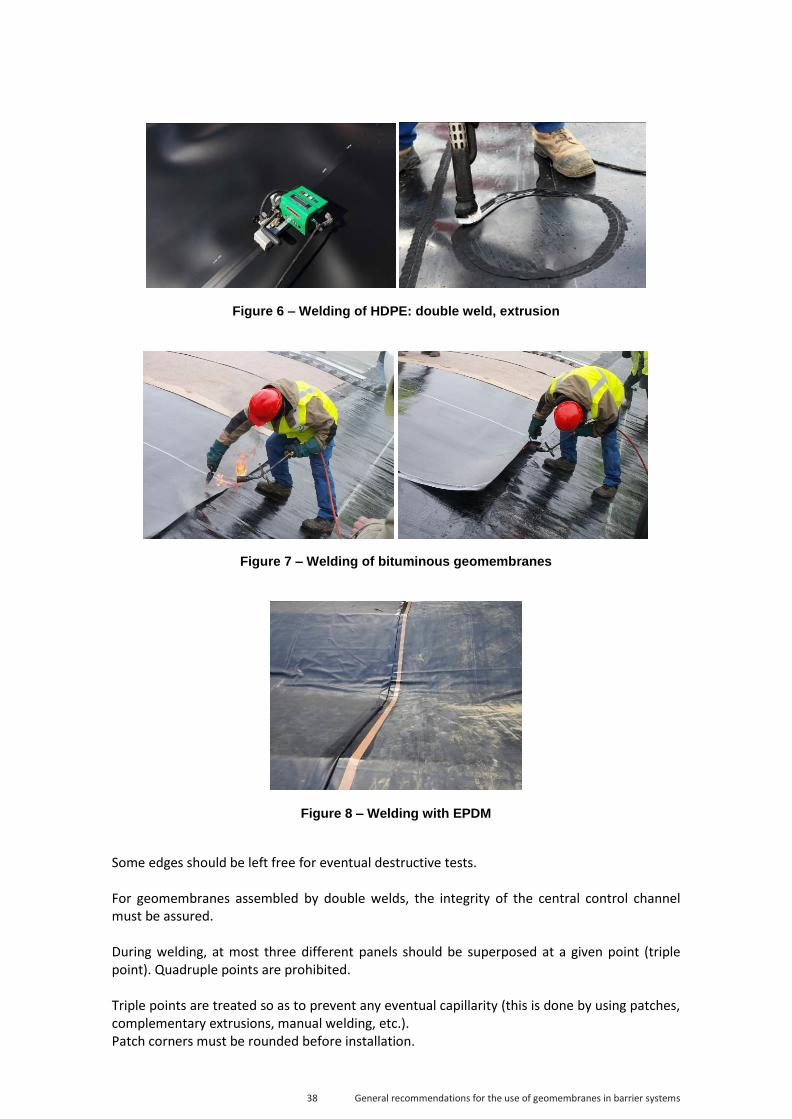
38 General recommendations for the use of geomembranes in barrier systems
Figure 6 – Welding of HDPE: double weld, extrusion
Figure 7 – Welding of bituminous geomembranes
Figure 8 – Welding with EPDM
Some edges should be left free for eventual destructive tests. For geomembranes assembled by double welds, the integrity of the central control channel must be assured. During welding, at most three different panels should be superposed at a given point (triple point). Quadruple points are prohibited. Triple points are treated so as to prevent any eventual capillarity (this is done by using patches, complementary extrusions, manual welding, etc.). Patch corners must be rounded before installation.

39 General recommendations for the use of geomembranes in barrier systems
Prefabrication Prefabrication allows welding to proceed independent of the weather conditions. Geomembranes of all chemical families can be prefabricated, except HDPE and bituminous geomembranes. Common rules The actual welding operation requires that the panels overlap each other. The minimum overlap is a function of the nature of the geomembrane and of the welding technique to be used. It exceeds the effective width of the welding. The seams constitute delicate points. They must be implemented with extreme care. It is prohibited to do them:
Under rain or underwater,
In the snow,
In the mud,
During strong winds, and
In extreme temperatures. In addition, one must not damage the underlying geosynthetics. Multiple assemblies require a fortiori especially careful work. Only a maximum of three elements may be superposed and this only at a single point (cf. Figure 9). A seam may be consolidated by a piece to reinforce or secure the weld at triple points.
Figure 9 – Overlaps and multiple assemblies.
4.3.5.2. Bituminous geomembranes
The overlap between two geomembrane panels is at least 0.2 m wide and the seams are done by propane-torch welding. The welding is done before or after the panels are positioned and is immediately followed by pressing the overlap with a roller. A specific equipement allows these operations to be done simultaneously. The seam lip is chamfered to complete the operation.
BAD 1 quadruple point
GOOD 3 triple points
Layer number i
Under layer
Upper layer

40 General recommendations for the use of geomembranes in barrier systems
4.3.5.3. P-PVC geomembranes
The overlap between P-PVC geomembrane panels should be at least 0.1 m wide and the seams are made by thermal welding (wedge welding or hot-air welding) with a central control channel. Automated welding equipment simultaneously welds and presses. Manual welding operations are accompanied by pressing with roller.
4.3.5.4. HDPE geomembranes
The overlap between HDPE geomembrane panels should be at least 0.15 m wide and the seams are made by thermal welding (wedge welding or hot-air welding) with a central control channel. Automated welding equipment simultaneously welds and presses. Extrusion is done after preparing the surface by adding filler material of the same quality as the geomembrane. This welding technique is reserved for singular points.
4.3.5.5. F-PP geomembranes
The overlap between F-PP geomembrane panels should be at least 0.15 m wide and the seams are made by thermal welding (wedge welding or hot-air welding) with a central control channel. Automated welding equipment simultaneously welds and presses. Manual welding operations are accompanied by pressing with roller. Extrusion is done after preparing the surface by adding filler material of the same quality as the geomembrane. This welding technique is reserved for singular points.
4.3.5.6. EPDM geomembranes
The overlap between EPDM geomembrane panels is at least 0.1 m wide and the seams are made by cold vulcanization via self-adhesive bands and a contact primer. These operations are followed immediately by pressing with a roller.
4.3.6. Anchoring
4.3.6.1. Anchorage at slope crest
This anchorage has two roles:
Prevent geomembranes from sliding on the slopes, and
Contribute to the resistance of the non-ballasted geomembrane to the uplifting caused by wind uplift or a current.
Experience shows that geomembranes should be held at the slope head before installing the anchoring material. In most cases, partial ballasting is carried out immediately in the anchor trench, and periodic fixations in the bottom of the trench (pins made of concrete-reinforcing rods) may also be used. Anchoring at the slope crest may also be done by:
Using an anchor trench,
Ballasting,
Mechanically attaching to a rigid support.
In each case, the anchor trench is sized by the designer (see Section 3.2.2—Geometrical considerations). The minimum size advised is 0.50 m deep by 0.50 m wide. With respect to the

41 General recommendations for the use of geomembranes in barrier systems
slope crest, it is situated at:
A minimum of 0.50 m for projects with an exposed geomembrane,
A minimum of 1 m for projects with a protected geomembrane. In practice, anchoring at the slope crest is done by burying in a trench as per the schematic diagrams in Figures 10 and 11.
Figure 10 – Schematic diagram of anchor trench for exposed geomembrane.
Figure 11 – Schematic diagram of anchor trench for protected geomembrane.
The geomembrane should lay horizontally on the bottom of the anchor trench, without rising
geomembrane
Protection geotextile
Geocomposite for protection, fixing, and soil reinforcement
Anchor trench
Backfilled trench
Anchorage trench
Bassin crest
Geomembrane
Geotextile
Bassin foundation
Vent
Geomembrane
Geotextile Gas drainage
Eartwork
Backfilled trench
Geotextile and geomembrane anchorage trench

42 General recommendations for the use of geomembranes in barrier systems
vertically up the exterior wall of the trench. The crest of the slope should be sloped so as to evacuate water away from the pond toward a collection point (e.g., peripheral gutter). Other ballast-type solutions are also used, as shown schematically in Figures 12 and 13. These should be constructed from non-erosive materials.
Figure 12 – Example of anchorage with top fill as load
Figure 13 – Example of anchorage with concrete border
Soil support Geotextile
Geomembrane
Fence Soil (> 0.30 m)
Staples (every 1 m)
Geotextile
Geomembrane
Staple
Concrete blocks

43 General recommendations for the use of geomembranes in barrier systems
The calculation of the load sections and the dimensions of the anchorage should take into account the conditions of friction (soil-geotextile, soil-geomembrane, geotextile-geomembrane) and the relevant load materials (nature, grain size distribution, density, etc.). If using freeboard anchorages (above the water level) with a rigid support structure (concrete beam, concrete pond, etc.), the three following solutions are proposed:
Mechanical clamping of a section; the dimensions of the clamped section should be defined so as to have constant pressure on the geomembrane,
Welding to a colaminated sheet mechanically attached a priori to the support, or
Welding to a synthetic section of the same type as the geomembrane and anchored a priori in the concrete.
For an unstable dike, the freeboard anchorages may be moved to the exterior foot of the dike. Recall that, for facilities with protected geomembranes, the anchoring at the slope crest must satisfy the French standard XP G38-067 (revised by prNF G38-067).
4.3.6.2. Anchoring at foot of slope
Anchoring at the foot of the slope is done to ensure impermeability of a slope or dike (see Figure 14) and to guarantee the seal between the geomembrane and impermeable horizontal layer (e.g., bottom clay layer). Anchoring at the foot can also contribute to the stability of the geomembrane under windy conditions.
Figure 14 – Example of anchoring at the foot in the case of a dike
Anchorage trench
Backfilled trench
Geomembrane
Geotextile

44 General recommendations for the use of geomembranes in barrier systems
4.3.6.3. Intermediate anchoring(s)
Ballasting is used for intermediate anchorages on all berms. These anchorages are used in the following cases:
For long slopes,
For transitioning between installation and operation phases,
As a contribution to controlling the wind uplift,
etc. The sizing of these anchorages follows the same principles as anchoring at the slope crest, taking into account the section of the geomembrane below the anchor point. Anchoring in trenches on berms is not advised because it interrupts the continuity of the drainage. In addition, a trench is not simple to construct and may lead to security issues.
4.3.7. Connection with neighboring works
Note: Solutions for connecting with neighboring works given in the paragraphs below take into account the nature of the effluents and the required degree of performance. These works (water inflow or outflow points, manholes, dam banks and tunnels, etc.) are most often made of cement, although sometimes of masonry, metal, or plastic. The concrete structures should be constructed so as to allow easy and robust joining with the geomembrane and should be adequately sized. Special attention should be focused on their geometry and the formulation of the cement, the planarity, the texture, the mechanical and chemical resistance, etc. The form of the facility should, to the extent possible, follow the profile of the support to allow the geomembrane to be attached while flat and not require three-dimensional tailoring. Concrete poured on site allows this constraint to be respected, whereas industrial elements (aqueduct heads, etc.) most often imply complex geometries that do not allow direct fixing of the geomembrane. In the backfill zones, and in particular the singular points, compacting should be carefully done to avoid differential settlement, which could create tensions in the geomembrane. Without justification to the contrary by the designer, a transitional piece should be systematically put in place (heel, reinforcement bracket, etc.) For the exposed vertical parts, plans should be made for intermediary fastenings spaced at most 3 m apart. In certain situations, the geomembrane may be permanently bonded to the support. General principle of connection (except for pipes)
For bituminous geomembranes, the impermeability of the connection is ensured by welding the geomembrane onto the support, which itself is puttied beforehand by cold-process cement. Mechanical fastening to the support is obtained by tightening a stainless-steel straightedge or a rigid pegged material (metal or plastic). The goal of such fastening is only to prevent tearing away of the geomembrane; impermeability is ensured by the welding (>0.2m width).
Synthetic geomembranes are preferentially attached to the stuctures by: o Mechanical fastening by a stainless-steel straightedge or a rigid material (metal
or plastic) for both submerged on non-submerged parts. At these points,

45 General recommendations for the use of geomembranes in barrier systems
impermeability is ensured by a compressed seam that is chemically compatible with the effluent to be stored (see Figure 15). The fastening pegs for the straightedge are made of stainless steel (e.g., an 8-mm-diameter is the minimum for a 4 cm ×0.4 cm straightedge). The pegs are separated by 15 cm at most and this spacing may vary as a function of the straightedge to ensure continuous compression of the seam,
o Colaminated sheets for the non-submerged parts (only for P-PVC geomembranes),
o Structural sections of a chemical nature compatible with that of the geomembrane and encased in the concrete during bonding of the latter. The geomembrane is then welded onto the structural sections.
A geomembrane seam cover may eventually complete these arrangements.
Figure 15 – Section of mechanical fastener based on a metallic straightedge
General principle for seals around pipes Four solutions are retained at present:
- Sealing the geomembrane around the concrete mass (see Figures 16–18),
Figure 16 – Example of seal around concrete mass
Metallic straightedge
Geomembrane
Compressed joint

46 General recommendations for the use of geomembranes in barrier systems
Figure 17 – Example of seal around concrete mass
Figure 18 – Example of seal around concrete mass
Flange–counter-flange system with seam chemically compatible with stored effluent,
Geomembrane flange (possibly prefabricated) dressing the extremity of the piping and assembled with the main geomembrane (see Figure 19),

47 General recommendations for the use of geomembranes in barrier systems
Figure 19 – Example of seal around piping via sleeve.
Seal via prefabricated welded parts chemically similar to the geomembrane. Note: Directly attaching a geomembrane to annealed pipes is not currently possible.
4.3.8. Certifications or qualifications
The construction companies involved may have certifications or qualifications. Certification gives a written assurance (certificate of conformity) that a service satisfies the relevant specifications of the certification rules. The qualification attests to the competence and professionalism of the company and to its capacity to undertake a technical service in a given field. The CFG participates in the development and establishment of certifications and qualifications with ASQUAL. Within this framework, currently available certifications are:
Service certifications for welding, which authorizes company welders to implement gas and/or watertight and resistant welds as a function of the geomembrane materials in use,
Service certifications of the worksite activity where site managers are authorized to deliver the given service, and
Companies’ qualifications.
Welding finish
Glue
Geotextile
Slope
Welding
>30 cm
>10 cm
Geomembrane
Compressible gasket clamp

48 General recommendations for the use of geomembranes in barrier systems
More information on these certifications and qualifications are available at www.asqual.com. The ASQUAL service certification—welding is based on the following:
A questionnaire to ensure the welder’s knowledge of welding conditions and the geomembrane materials to be welded,
Vetting of a worker’s practical competence and his mastery of the equipment and the automation techniques through assemblage (automated or manual), and
Tests by independent laboratories to ensure the quality of the welded geomembranes.
The ASQUAL service certification—site manager is based on the following for each individual:
A questionnaire to ensure his or her competence regarding all the families of ASQUAL-certified geomembranes, on the organization of the sites where the geomembranes are installed (management of one or more teams), on hygiene, and on security,
An examination of reports of finished works to ensure the capacity to monitor a work site (decision making for sites under management, representation of company, management of internal quality control of sites: material, control methods, recording and traceability of installation and welding of geomembranes).
Being qualified by ASQUAL is voluntary for companies; the qualification consists of verifying that the company’s quality-assurance system satisfies the technical, organizational, and administrative criteria of the ASQUAL certification rules. A prerequisite for such qualification is the service certification Geomembrane application—welding and on-site responsibility. A satisfaction survey is completed by the ordering agency and the user, who are clients of the company. ASQUAL periodically monitors that the certified and qualified companies remain in conformity. Note that:
ASQUAL certifications are developed under well-defined conditions (under shelter, dry, clean, etc.) that do not always reflect conditions that may be found on site (climactic conditions, geometry of site, connection to neighboring works, etc.),
The presence of welders and site managers authorized to deliver ASQUAL-certified services do not remove the necessity of an independent control organized by the contractor and executed under the responsibility of the contractor.
4.4. Installation of protection layer During the installation of an eventual protection layer (above the LS), care should be taken to verify that the arrangements made for the installation do not degrade the impermeability. Too often this phase is not undertaken by the seaming company but by an ordering agency or a sub-contractor that is not necessarily aware of the fragility of the geomembrane. For this reason, we emphasize that any degradation in the impermeability at this phase must be reported so that the seaming company can, to the extent possible, make repairs. It is advisable that a team from the seaming company be present during this phase so that they can repair any eventual damage as fast as possible. To ensure the stability of the protection layer (organic soil, sand, sand-gravel mixture, rockery, etc.), it is built from the slope bottom to the top of the slope. Degradations are often caused by heavy equipment or other elements (prefabricated slabs, formwork elements, etc.) or by negligence (e.g., formwork elements placed directly on the geomembrane). Consequently, during the installation of the covering materials, any eventual

49 General recommendations for the use of geomembranes in barrier systems
circulation of heavy equipment should occur only on specially adapted and sufficiently thick protection layers (the thickness should be validated in test pads). Such tracks for the circulation should be designed to avoid the compression of the protection structure on the geomembrane complex and the eventual shifting, displacement, and compaction of the aggregates. Likewise, it must be verified that the presence of the LS does not interfere with the proper implementation of the protection layer (wrinkles in geomembrane too high vs thickness of the protection layer). One may also consult the recommendations of the CFG fascicule entitled “Recommendations for protecting geomembranes from puncture”5 (In press during the development of the present document).
5 Recommandations pour la protection contre l’endommagement des géomembranes

50 General recommendations for the use of geomembranes in barrier systems
5. Acceptance and control of construction
5.1. Domain of control LS components and the arrangements for installing them are subject to control. In this chapter, no distinction is made between internal and external control; instead we enumerate a certain number of tasks to be done (domain of application of control). The list of controls to do and their breakdown is given in the specifications. There are several types of controls that can be activated at different times:
Control of documents begins before the onset of work at the site. Included are documents such as the QAP, requests for approval of materials, the SHSP, the GDP, the plans for the facility and the installation methods. This type of control is to be pursued during the entire construction period in consultation with the site journal, the control files, etc.,
Control of the installation of the LS itself is to be done on site and includes non-destructive control and samplings taken for destructive tests done in laboratories.
5.2. General recommendations regarding control of a lining system
5.2.1. Control of site organization
Site organization is discussed in the QAP of the mandated company and in that of the seaming company if it is a sub-contractor. It must be verified that the personnel and materials promised in these documents are indeed present. For example, the presence of certified welders and site managers or the certifications must be verified.
5.2.2. Control of areas for storage and product handling
The areas for storage and handling should be large enough and have sufficient weight-bearing capacity to hold the required materials in accordance with the manufacturer’s directions. The materials should be stored in accordance with the directives of 4.3.2. All protection elements put in place by the supplier to protect the various conditionings should be conserved for as long as possible. They are to be removed only at the last moment to allow the materials to be maintained in good condition and to allow eventual mechanical degradations to be easily visible. Storing the LS components should be done in accordance with the manufacturer’s directions (maximum height, number of stacked rolls, eventual load-bearing structure, etc.). Depending on the meteorological conditions at the site (intense sunshine, extreme
51 General recommendations for the use of geomembranes in barrier systems
temperatures, etc.), it may be necessary to put in place a complementary protection or to shelter some materials. In this case, the shelter should be of appropriate dimensions (a counter example is storage in containers to protect from heat).
5.2.3. Control of materials and equipment upon reception at site
The control of materials delivered to the site consists first of verifying the documentation:
Verifying the tags of the rolls and panels: o Trade name, o Features (chemical nature, thickness, mass per unit area, etc.), o CE marking according to the standards in force for the facility or for the
intended use of the materials, o Identification number of the rolls, and o Certifications,
Control of accompanying documents (manufacture’s control). This control should be done upon receipt of goods and can be done on site a posteriori by all authorized people (company management, contractor, independent control, etc.). It can be done by identification tests of samples taken from the stock so as to verify the conformity of the shipped products to the certified specifications, certifications, technical specifications). These tests are normally done by an independent review or in a Cofrac-accredited laboratory for the specification tests. The program of identification tests and the breakdown between the various controls are to be stipulated in the specifications. The equipment for sealing the LS should also be verified. Their good general condition and proper functioning must be ensured. For certain equipements that can be calibrated (field tensiometer, etc.), the validity of their certificates must be verified.
5.2.4. Test pads and performance tests
In certain cases, test pads or performance tests should be implemented. A test pas is an area that may be situated outside the construction site where multiple arrangements may be tested to help in choosing that most suited for a particular situation at the site. Once the choice is made, the other possibilities are eliminated. To set up a test pad, please refer to the “Guide to conception and use of LS test pads”6 and the CFG document entitled “Recommendations for protecting geomembranes from puncture”7 (currently in development as the present document goes to press). A performance-test pad is normally situated on the construction site or at a site whose characteristics closely resemble those of a construction site. Here, the procedure to be applied at the construction site is implemented with the personnel and equipment given in the QAP. This test pad allows the ability of the personnel to properly execute the procedure and operate the equipment to be verified. The performance tests involved may be destructive or nondestructive. Once the performance tests are completed, this test pad may be left in place or taken down, depending on the results.
6 Guide pour la conception et l’exploitation de planches d’essais sur DEG
7 Recommandations pour la protection contre l’endommagement des géomembranes

52 General recommendations for the use of geomembranes in barrier systems
Before beginning to install the LS, tests should be done to verify that the personnel and equipment assigned to the task will provide the desired results. These tests may include identifying the LS elements to verify that the materials received indeed have the characteristics given in the specifications and in the technical specifications or certificates.
5.2.5. Control associated with acceptance and installation of support
structure
Control of compaction and bearing capacity is done by the earthworks contractor, their internal control, or by an independent control by the contractor and is subject to acceptance upon receipt. Next, during a triparty reception (earthworks contractor, seaming contractor, and main contractor), the control of the support structure consists of a visual inspection of:
The general state of the support structure (homogeneity, absences of protruding or potentially puncturing elements, presence of mud, etc.),
The planarity,
The geometry (proper slopes, treatment of angles, etc.),
The anchoring trenches (sizing cf. §4.3.6 Anchoring, treatment and installation of LS),
The treatment of inflowing water (runoff, seepage, etc.). These controls are done according to the demands of the project stage or of the climactic conditions.
5.2.6. Control of layout plan
The goal of verifying the layout plan is to detect eventual nonconformities such as quadruple points, horizontal welds on slopes, etc.
5.2.7. Control of construction-phase plan
The control of the construction-phase plan serves to detect incompatibilities such as installing penetrating devices after the LS is in place, other work that requires direct circulation on the LS, etc.
5.2.8. Control of impermeability
The present document distinguishes the following three levels of control, each of which is described below:
Internal control,
External control, and
Independent control.
Controls and their frequency depend on the nature of the project, of the consequences class of the project, its dimensions, its use, the use of certified products and installers (welders, site managers, companies).

53 General recommendations for the use of geomembranes in barrier systems
5.2.8.1. Internal control
Internal control is carried out by personnel from the installation company who participates in the installation of the LS. It is done by the welder (control of welding parameters, visual control, etc.) and/or by the site manager (control upon receipt of materials and control of welding). These controls involve all weldings and require that the proper equipment is on site and functioning (vacuum chamber, field tensiometer, inflation needles with pressure gauge, etc.). They include, among other things:
Control of tags,
Control of equipment,
Control that the layout plan is being respected,
Visual inspection of the continuous part of the LS components and assemblies,
Control of equipment parameters,
Control of the quality and conformity of the entirety of the welds,
… The results of the various controls are formally reported in files that may be consulted on site by the external control agent during the review of documentation. When requested, samples and specimens obtained for calibrating the machines each time work is restarted shall be kept in a safe place on site until the end of the construction. This will allow, if need be, to do a posteriori tests on the conserved samples. The internal control plan should be described in the site-control plan and in the QAP of the company and should be based on the technical documents for the given type of facility.
5.2.8.2. External control
External control, which is done for the company by personnel who do not participate in the installation of the LS (e.g., quality-control people from the company, external consultant), consists of control by sampling and allows the internal control to be validated. It can only be done in the areas already verified internally. Its frequency is defined in the specifications and concerns at least 30% of the welds. This control can include samplings destined for destructive tests on materials for identification or on seams. The external control plan shall be described in the site-control plan and should be based on the technical documents for the given type of facility.
5.2.8.3. Independent control
The independent control is done the by the general contractor or, preferably, by an external consultant with the competence to act as an agent for the contractor. The control is done by sampling and allows the arrangements made by the company to be validated to ensure quality control. It can only be done once the other controls are completed. The independent control agent must possess his own equipment for the control.
54 General recommendations for the use of geomembranes in barrier systems
The control consists of a review of documentation, non-destructive controls, and samplings taken for later tests in a Cofrac-accredited laboratory. The independent-control plan shall be described in the specifications (seaming work and independent control) and should be based on the technical documents for the given type of facility. It should concern at least 30% of the seams.
5.2.9. Control methodology
5.2.9.1. Non-destructive control
The methodology to execute these various controls are described in the CFG guide entitled “Presentation of methods to detect and localize holes in geomembranes.”8 Visual inspection It may be done continuously and at all levels of control. It concerns all parts of the facility and all the components of the LS and the assemblies. Control with pressurized air This control concerns the automated double welds with control channel. It verifies the continuity and impermeability of the control channel and thus the bordering seams. Note: This is not a mechanical trial; a weld can be gas and/or watertight yet still fail to provide the mechanical resistance required by the market. Control by pressurized color liquid This control concerns the automated double welds with control channel. It verifies the continuity and watertightness of the control channel and thus the bordering seams. It allows visualization of eventual surface defects on the geomembrane. It may be complemented by a thermal-imaging camera that, by using a warm liquid, would allow visualization of the sub-surface defects. Control by vacuum chamber This control concerns manual welds, extrusions, and singular points. It verifies the continuity of manual welds. It should be complemented with a penetration test (except for EPDM). Note: This is not a mechanical test. This control is always doable (irregular support, inaccessible assemblies, etc.). Penetration test This test concerns manual assemblies and extrusions of geomembranes (excepting EPDM) and completes the methods cited above. It verifies the continuity and, to some extent, the proper adherence of the manual welds and extrusions. Dielectric control This control, which exists in several forms, concerns the whole LS surface. It allows detection thus repair of small-scale or large-scale cross defects. It can be done during the construction phase, at the acceptance of the barrier construction, and, for certain methods, after installing the confinement.
8 Présentation de méthodes de détection et de localisation de défauts dans les dispositifs d’étanchéité par géomembranes

55 General recommendations for the use of geomembranes in barrier systems
Ultrasound control Currently, this method is applied to bituminous geomembranes to control assemblies. It allows detection thus repair of welding defects and is limited to the planar parts of the facility. Control by air lance This control consists of directing pressurized air under the seam overlap. The equipment for testing the impermeability by air lance consists of a source of compressed air to be expelled through a 4.8-mm-diameter nozzle (3/16”). The minimum air pressure at the nozzle outlet is 345 kPa (50 psi). The nozzle should be oriented toward the upper lip of the seam and maintained less than 51 mm (2”) from the seam. This test is designed to verify the continuity of the assemblies. The air lance test is detailed in ASTM D4437. Control by impoundment This control may be done after the installation of the geomembrane. It consists of completely or partially filling the facility to verify its barrier function under load. We measure the variations in water level and the eventual flow rates in the drainage system. Analysis of the results should consider the variations due to atmospheric conditions (precipitation, evaporation, etc.) during the tests (note that the duration of the tests depends on the size of the facility).
5.2.9.2. Destructive tests
Destructive tests are done to verify whether the samples under test satisfy the requirements given in the specifications and in the references cited therein. These tests may concern the materials for identification purposes, or the assemblies. For material-identification tests, the list of tests and their frequency and breakdown between various controls is to be determined in the specifications (or, where appropriate, by independent control) and in the control plan. For what concerns the welds, the tests to determine the mechanical characteristics can be done as a function of the chemical nature of the geomembrane and of the type of facility. Samplings are to be taken from outside of sensitive areas and, preferably, toward the extremity of the welds (to ensure the continuous area is impervious). These tests are subsequently described. Tensile peeling This test characterizes the mechanical resistance and the rupture mode of a welding when the seam borders are subjected to a force parallel to the direction of the border. Tensile shearing This test characterizes the mechanical resistance and the rupture mode of a welding when a seam is subjected to forces in the plane of the geomembrane. During peeling and shearing tests, the observed characteristics come partly from the seam resistance and partly from the rupture mode of the welding. The welding factor is the ratio of the resistance of a seam obtained from one of the two preceding tests to the tensile resistance of the base material. It is expressed in percent. This characteristic applies only to HDPE and bituminous elastomeric geomembrane welds. The specifications (criteria) of each characteristic are fixed by the specifications. Minimum values are proposed in Appendix C.

56 General recommendations for the use of geomembranes in barrier systems
5.2.10. Controls associated with installation of protection layer
This consists of the control with respect to the installation of the protection layer (nature, thickness, implementation procedure, etc.) and also of properly taking into account the arrangements described in §4.4 “Installation of protection layer.”
5.2.11. Control of as-built report
The control of the end-of-site report can only be done by a person involved in the site from the beginning (contractor, independent control agent).This task alone is not sufficient to establish the proper completion of the facility because the elements in the file must be compared with those observed during the entire construction period. The control of the file and notably of the as-built drawing allows the general contractor to know the state of the facility at the end of the seaming work. This control allows us to validate the presence of the constituent elements of the as-built report, which include at least the following:
The QAP,
Human means (nominal list) and equipment,
As-built drawing (with assemblies identified),
Photographs,
Site logbook,
File for reception of support and materials,
Files for controlling welds under the responsibility of the site manager,
Files identifying non-conformities and their treatment, and
Files for future interventions on site.

57 General recommendations for the use of geomembranes in barrier systems
6. Quality assurance
The owner defines the expected function of the facility in terms of functional quality. The general contractor translates the needs in terms of required quality in the form of contractual requirements (performance, delay, cost). The quality of the facility corresponds to the satisfaction of the needs. Obtaining a quality facility requires taking into account:
The conformity of the materials,
The proper execution of tasks,
The proper scheduling of tasks, and
The possible risks.
It is common that the cost for control and the quality-assurance plan represents roughly 10% to 20% of the total cost of the facility. To well understand this chapter, the following vocabulary is reviewed.
6.1. Terminology for quality assurance The following terms are defined in the standard NF EN ISO 9000 or in the law regulating public contracts. Anomaly: deviation from that which is expected. Comment: the treatment of anomalies must be defined in the quality-assurance documents of the work site (QAP and QMP). Defect: nonconformity related to an intended or specified use. Functional quality: capacity to fulfill the functions defined by the project manager. Independent control: control done by the general contractor or by an organism mandated by the owner. Comment: this control can consist of an on-site audit of the company’s quality system, the control of the controls, and tests done to validate the results of the internal control. Recommendation: the organization doing the external control should not be associated with the project manager. Internal control: control by the company to ensure the quality of its product or service. It includes:
The internal control done by those executing the work,
The external control done by a company service that is independent of the site manager or by an organization mandated by the company.
Nonconformity: non-fulfilment of a requirement.

58 General recommendations for the use of geomembranes in barrier systems
Organizational diagram of quality assurance plan (ODQAP): diagram of provisional organization for quality-assurance plan established by the company and attached to the commercial proposition. Comment: this diagram makes it possible to judge the aptitude of the company to obtain the required quality. Quality: degree to which a set of inherent characteristics of an object fulfils requirements. Quality assurance plan (QAP): for the given facility, a document explaining arrangements made by a company to obtain the required quality. Comment: for example, the means in which control is implemented. Quality master plan (QMP): document based on quality-assurance plans and developed by the project manager in coordination with the companies participating in the market. Comment: the QMP defines all actions required to obtain the desired quality; for example, the interaction between the earthworks contractor and the seaming contractor. Required quality: translation of functional quality into contractual requirements or imposed by the owner and expressed in terms of required results or means. Comment: for example, definitions and specifications of the seaming mechanism—drainage by geosynthetics. Stopping point: point beyond which work should not continue without the agreement of an external control. Comment: for example, the acceptance of the support before the installation of the LS.
6.2. Organization of actions to ensure quality The organization to obtain the requisite quality for a facility requires the intervention of various partners from the design to the operation of the facility. Table 6 shows the roles and documents required of each participant to reach this goal.

59 General recommendations for the use of geomembranes in barrier systems
Participant Phase
Project manager User
Contractor Company
Definition or requirements
Functional quality Definition of conditions of use
Conception Required quality (Constitution of LS, specification, implementation document, etc.) Proof of authorization for controls
Public tender Minimum quality requirements relative to means and controls
Offers Technical memory inducting the ODQAP
Preparation of work site
Development of QMP, which unites the QAPs of the various construction participants
Development of QAP Definition of means put in place to obtain required quality
Works Independent control (mandate an organization)
Follow-up, lifting stopping points, and external control (if mandated)
Execution of works in accordance with the QAP As-built drawings
Operation Application of QAP for operation of facility
Table 6 — Organization of actions to ensure quality
6.3. Content of Quality Assurance Plan This paragraph discusses only the QAP of the company that wins the tender for the project (and its subcontractors) and must contain at least the following information:
Identification et description of works,
Organization of the company: o Nominal organization chart, o Description of job functions of personnel, o Decisional flow chart, o Organization of internal control,
Means: o Qualification of personnel (service certification, etc.), o Means of implementation and control:
Description of welding equipment, Description of automated means (with their calibration), Description of means of hoisting and peeling, Electrical means,

60 General recommendations for the use of geomembranes in barrier systems
Materials and geosynthetics: o Technical description of materials to be used, o Means to guarantee traceability of the product and its implementation,
Execution of work: o Implementation methods, o Security arrangements adapted to installation of geosynthetics, o Description and frequency of controls, o Documentation of monitoring, o Treatment of nonconformities,
Acceptation of work: o Contradictory measurements, o Procedure for acceptation,
Document archiving.

61 General recommendations for the use of geomembranes in barrier systems
7. Guarantees, insurance, disputes
7.1. Role of the various parties The parties are as follows:
The project manager or the owner,
The CQA,
The general contractor,
The company (with its suppliers and eventual sub-contractors). The project manager is not expected to be a technical expert. She must rely on the contractor for the design and implementation of the facility, and orders an external control (see § 5.2.8.3 Independent control) to ensure the quality of the facility. She is nevertheless responsible for the proper operation, maintenance, and surveillance of the finished facility. The general contractor provides the technical competence to design and build the facility (directs the work and acceptation of materials and equipment) or uses specialists in the domain of LSs and the associated procedures to install them. Note: It is recommended to use a single company to install the entirety of the LS geosynthetics. The company is responsible for the supply of constituent materials and the construction of the facility, including installing the LS. It must thus manage the suppliers or manufacturers and ensure the following:
The compatibility between the principle characteristics of the product and the specifications,
The availability of technical specification for the products and the means of their identification,
The development of the QAP,
The provision of the QAP,
The availability of the manufacture’s control documents for the geosynthetics,
The provision of a liability insurance policy for the company, and
That all delays are respected (delivery, preparation, handling, and storage). The company must also demonstrate her competence to construct the facility and notably the installation of the LS or, if authorized, to use a qualified sub-contractor and furnish the following elements (for herself or the eventual sub-contractor):
References to similar finished works,
The qualifications of the specialized personnel (e.g., ASQUAL),
The availability of the material required for installation, handling, and internal control,
The QAP with the internal control procedures,
Proof of a liability insurance policy, and
If applicable, proof of a specific guarantee.

62 General recommendations for the use of geomembranes in barrier systems
7.2. Guarantees The guarantee expected by the project manager for the LS consists of the ensemble of guarantees furnished by the company responsible for the LS or by the companies that participate separately in the construction of the various structures. These partial guarantees correspond to the various successive acceptations. In particular, they concern the following properties that the facility and LS are expected to provide:
For the lifetime of the LS guarantee, the geomembranes, geotextiles, and protection layers should be guaranteed against improper aging,
For the barrier function, the integrity of the geomembrane and its assemblies should be guaranteed, as demonstrated by the results of quality control measures of the products and the installation and welding work. These guarantees require a commitment regarding the maximum leak flow,
For monitoring the facility: a guarantee of the proper functioning of the filtering and drainage system.
The guarantees may be adjustable depending on the facility and should be adjusted to reflect the solution selected for the LS. Guarantees related to the performance of the facility are subject to the existence of a monitoring system. Binding procedures and interpretation protocols should be established. Those related to the performance of products must be defined a priori in the standards or by the designated operation modes.
7.3. Insurance The domains of application targeted by this document (see Section 1.3) are cited in article L.243-1-1 of the French Insurance Code and are not subject to inherent defect insurance. The project manager can demand an insurance policy, although it takes the form of a contractual specification. This arrangement is neither obligatory nor systematic. It must not be confused with civil liability (which is obligatory for the project manager, the independent auditor, and the company), which covers problems caused by third parties (but not those caused by the facility). If the market or the conditions of the facility require it, the company may be forced to obtain an insurance policy that guarantees, in the case of damages affecting the durability or cleanliness of the facility, the financial consequences of inherent defects for which the company is responsible as per article 1792 of the French Civil Code.
7.4. Litigation The cases discussed here do not involve amicable settlements because those are not concerned by the obligatory inherent defect guarantee. Litigation may be resolved amicably directly between the project manager, the contractor, and the company, notably by mediation or arbitration. The disputes submitted to arbitration should conform to the FNTP rules of mediation and arbitration for a single arbiter (or three arbiters if desired by the parties).

63 General recommendations for the use of geomembranes in barrier systems
If no amicable settlement is found, the legal process begins by designating an expert to conduct an investigation. The expert is designated by the appropriate court. The expert provides a preliminary report and a full report that identifies:
The damages,
Their origins,
The possible repairs, and
Their cost and duration. The expert provides the judge with the elements for determining liability. The expert’s job stops with the filing of the report. After this, the judge determines the liabilities and the share for which each party is responsible for bringing the facility back to conformity. Next, the various parties agree, based on the expert’s report, to carry out the repairs. If no agreement is reached, one of the parties (e.g., the project manager) can file an application on the merits, and a trial ensues.

64 General recommendations for the use of geomembranes in barrier systems
Appendix A: Glossary
GENERAL TERMS Geomembrane9 (Excerpt of the standard NF P84-500) Manufactured product for civil engineering, minimum of 1.50 m wide (- 0.05 m), thin, flexible, continuous, gas and/or watertight at the output of the assembly line, minimum effective thickness10 of 1.00 mm over the entire surface of the panel and continuously weldable on each face by thermal welding, vulcanization, or self-adhesive bands depending on the nature of the product. Lining system (LS) The components consist of 1. a support structure; 2 a barrier; 3. an upper protection layer, if necessary.
Figure 20 — Structure for lining system.
Lining system A structure consisting of a single geomembrane or eventually two geomembranes separated by one or more of the following elements: drainage network, soil layer, protective elements.
Support structure Structure placed between the bottom form and the barrier. It may consist of
the form layer;
the support layer;
9 With the current techniques the following are not geomembranes: products with function thickness less than 1 mm, products with widths less than 1.5 m (−0.05 m), products whose impermeability derives
essentially from a clayey material.
10 Also called functional thickness.
STRUCTURE FOR LINING SYSTEM
PROTECTION LAYER (Optional)
BARRIER
SUPPORT STRUCTURE

65 General recommendations for the use of geomembranes in barrier systems
drainage mechanisms (water and gas). Form layer Supportive layer that lies on the bottom form. Support layer Supportive layer on which lies the barrier. Bottom form The surface on which lies the barrier. Protection layer (optional) Structure laid on the barrier to protect it during installation and operation.
TERMS RELATED TO GEOMEMBRANE STRUCTURE Composite geomembrane Manufactured product formed by a superposition and welding of several components, of which at least one is a geomembrane. The components other than the geomembrane are called “associated materials.” They cannot be dissociated from the geomembrane without it being altered. Associated material For a composite geomembrane, the synthetic or mineral layer that adheres to one or both faces of the geomembrane.
Reinforced geomembrane Geomembrane with a reinforcement consisting of a structure of reinforcing elements.
Ply An impermeable manufactured sheet or film of homogeneous chemical composition that constitutes the base element for manufacturing a geomembrane.
Single-ply geomembrane A geomembrane made of a single ply.
Multi-ply geomembrane A geomembrane consisting of several indissociable plies.
Delamination of a geomembrane Separation of the material layers of a geomembrane; for example, separation of the plies of a multi-ply geomembrane or of the associated materials of a composite geomembrane.
Mass per unit arera Mass per unit surface area (express in grams or kilograms per square meter). Total thickness Thickness of the geomembrane, including reinforcement, markings, and surface profile as well as any associated materials in the case of a composite geomembrane.
Effective thickness Minimum thickness (that contributes to the barrier function) of a rough or reinforced membrane. See standards NF EN 1849-1 and 2.
Surface pattern Raised motif on surface of geomembrane, generally obtained by blowing, projection, calendering, or embossing and whose goal is to improve friction characteristics.
Watertightness A geomembrane is considered watertight if, under the measurement conditions stipulated by the standard NF EN 14150 (during seven days and under a differential pressure of 100 kPa), the

66 General recommendations for the use of geomembranes in barrier systems
cross water flux through the continuous parts of the geomembrane (excludes seams) is less than 10−5
m3 m−² d−1
.
TERMS RELATIVE TO THE FABRICATION OF A GEOMEMBRANE Geomembrane fabricated on site A geomembrane fabricated at the location where it is to be applied. It may be a single-layer (monolayer) or a multilayer geomembrane.
Manufactured geomembrane A geomembrane fabricated in a factory. The geomembrane is fabricated in the form of rolled panels.
Panel The production width of a geomembrane. Usually, a geomembrane band.
Spire Each of the towers of rolled geosynthetic.
Sheet (or panel) Ensemble of panels permanently assembled in the factory or at a workshop near the application site. Calendering* Process consisting of compressing a material by passing it between two cylinders.
Coating* Process consisting of depositing a thin layer of liquid or paste on a support (generally a textile).
Impregnation* Process consisting of thoroughly penetrating a support (generally a textile) with a liquid material.
Extrusion* Process consisting of forcing a material, heated or at ambient temperature, through a die with the appropriate cross section.
Machine direction = machine direction Direction in which a manufactured geomembrane advances during its fabrication.
Cross direction Direction perpendicular to the production direction.
*These definitions apply only in the context of geomembranes.
TERMS RELATED TO ASSEMBLED GEOMEMBRANES Welding Sheets (or panels): welding is generally done by thermal welding with or without filler material or by solvent welding, bonding, or vulcanization with or without filler material. Seam Zone where two sheets (or panels) are joined; by extension may also designate the result of the welding operation.
Weld Method of assembling surfaces that are softened either by application of solvent, or more generally by heating. Simultaneously, pressure is applied on the exterior faces of the welding. Double weld
67 General recommendations for the use of geomembranes in barrier systems
Method of welding whereby two parallel seams are implemented simultaneously; it is achieved by automated welding and contains a nonwelded zone between the seams. This central channel generally serves to do pressure tests of the watertightness. Solvent weld Method of welding of thermoplastic products in which the surfaces are softened by using solvents and joined by applying pressure; the solvent is generally eliminated by absorption or evaporation. Note: the terms “cold welding” or “solvent bonding” should be avoided. Thermal welding Method of welding in which the surfaces are softened by heating. Upon contact, the high temperature of the two surfaces allows them to partially fuse. The heating may be done by using a metal blade, an air jet, ultrasound, or a high-frequency electric field. In certain cases, the welding is done with the aid of filler materials softened by heating. Automated welding Welding method in which an automated system maintains the principle welding parameters constant (pressure, temperature, speed). Extrusion welding Welding by adding softened material. Cold vulcanization Chemical procedure for assembling EPDM geomembranes. Welding with strip of filler material Joining two surfaces by interleaving between them a self-adhesive film (generally reactivated).
Bonding Method to join two surfaces by using an adhesive material, liquid, or paste or in the form of a film that may be cold or hot. Seam cover A geomembrane panel bonded or welded over a seam to mechanically reinforce it and/or improve its impermeability. Marouflage Procedure whereby pressure is exerted on a geomembrane surface during or immediately following its welding or bonding. Generally done by using a roller.
TERMS RELATED TO BASIC MATERIALS AND TO PHYSIO-MECHANICAL BEHAVIOR OF GEOMEMBRANES Polymer Product consisting of molecules of large molecular weight and whose structure is essentially characterized by the repetition of one or several types of monomers, thereby forming a chain or macromolecular network. Thermoplastic (substantive) Bondable polymer that can be repeatedly and reversibly softened by heating and hardened by cooling in a temperature range that characterizes the material and without chemical transformation. Thermohardened A polymer that is transformed into a non-weldable crosslinked material upon heating or by other physical or chemical means; it can be flexible (rubber) or rigid. It is generally insoluble in most solvents although it may expand upon contact with the latter. Elastomer A quasi-elastic polymer; the elasticity may be complete or partial depending on the product in question or on the magnitude of the applied force.

68 General recommendations for the use of geomembranes in barrier systems
Plastomer Polymer exhibiting plasticity at ambient temperatures; also exhibits thermoplastic properties. Polymer bitumen Bitumen modified by adding polymer(s) whose chemical composition and conditions of fabrication were designed so that the behavior of the mixture is that of the polymer. Plastomer bitumen Bitumen modified by adding plastomer(s) whose chemical composition and conditions of fabrication were designed so that the behavior of the mixture is that of the plastomer. Rubber or synthetic rubber Elastomer that is already or may be (in the case of cross linked and cross-linkable elastomers, respectively) in an essentially unbondable state and that is insoluble in all solvents, although it may expand upon contact with the latter. When cross-linked they exhibit elastic or quasi-elastic behavior. Note: A synthetic rubber in its modified state cannot easily be remolded by heating or moderate pressure. If it contains no extender, it reverts in 1 min to less than 1.5 times its initial length after having been stretched at normal temperatures (18 to 29 °C) for 1 min to twice its original length. Thermoplastic elastomer Polymer with an essentially elastic reaction at low temperatures (operation) but with a plastomer reaction at high temperatures (transformation). Elasticity Property whereby materials revert to their original form and dimensions once the forces that deformed them are no longer exerted. Elastic limit The greatest mechanical load that a material can withstand without undergoing permanent deformation once the load is removed. Viscoelasticity The general behavior of a material; intermediate between a purely elastic state and a purely viscous state. This behavior is a function of temperature and of the load and its speed and the length of time over which it is applied. Plasticity Tendency of a material to remain deformed after the forces that deformed it are reduced below the yield point. Yield point, pseudo yield point First point on the stress-strain curve at which the deformation increases without increasing the stress. Emulsion Heterogeneous system consisting of the dispersion of fine globules of a liquid (discontinuous phase) in another liquid (continuous phase). Plasticizer Weakly or non-volatile substance incorporated into a plastic to lower is softening range in order to facilitate the application of the latter and increase its flexibility or extensibility.
CHEMICAL DESIGNATION Oxidized bitumen Also called air-blown bitumen, it is obtained from penetration bitumen by adding oils and injecting air at high pressure. It plays a role in the manufacture of membranes because it can serve as an underlayer for bituminous geomembranes, where it is useful for thermal bonding. Polymer-modified bitumen Bituminous linker whose properties are modified by applying a chemical agent that, after being introduced into the base bitumen, modifies the chemical structure and the physical and mechanical properties of the former.

69 General recommendations for the use of geomembranes in barrier systems
Polyolefin A family of polymer products based on pure olefins (polyethylene, polypropylene) or on mixtures thereof with other monomers (copolymers); the olefinic monomer(s) account for most of the mass. Polyethylene Ethylene polymer; a polymer made only of carbon and hydrogen, globally linear in structure, saturated, and with no substitution. High-density polyethylene (HDPE) HDPE geomembranes are thermoplastic geomembranes with a typical density of 940 kg/m3. This density accounts for the entire composite (medium-density PE and all the additives, including carbon black). The medium-density PE used in HDPE geomembranes has a density of the order of 926 to 939 kg/m3. Consequently, the addition of carbon black increases the density of the geomembrane. Example: 2% carbon black increases the density of a HDPE geomembrane by 9 kg/m3. Thus, a medium-density PE with a density of 932 kg/m3 and 2% black carbon results in a HDPE geomembrane with a density of 941 kg/m3. Flexible polypropylene (F-PP) A linear, saturated propylene polymer made only of carbon and hydrogen, with a methylene radical on every other carbon in the chain. Flexible polypropylene differs from polypropylene by the addition of an ethylene-polypropylene elastomer, which gives it significant flexibility. Ethylene propylene diene terpolymer (EPDM) A terpolymer of ethylene, propylene, and diene; the polymer chain contain unsaturated sites, which allows for eventual vulcanization. Styrene-butadiene-styrene copolymer (SBS) Copolymer made from styrene and butadiene; it is a thermoplastic due to the sequential arrangement of styrene and butadiene in the chain (block copolymer); it is often used for manufacturing elastomeric bitumens. Polyvinyl chloride (PVC) Polymer consisting of chloride and vinyl; it is often used to manufacture plasticized geomembranes (P-PVC). Isobutylene-isoprene copolymer (butyl rubber) Copolymer obtained from 98% isobutylene and 2% isoprene; the polymer chain contains unsaturated sites (isoprene), which allows it to be vulcanized.

70 General recommendations for the use of geomembranes in barrier systems
Appendix B: Bibliography and normative documents
Bibliography:
Géomembranes, Guide de choix, ROLLIN, A. ; PIERSON, P. ; LAMBERT, St., 2002, Presses internationales POLYTECHNIQUE, Montréal, 274 pp.
Descriptions recommandées des Géosynthétiques, Fonctions, Terminologie des Géosynthétiques, Symboles Mathématiques et Graphiques, Version Française réalisée par N. Touze-Foltz et C. Barral, I.G.S., 2011, 32 pp.
Publications of the French Committee on Geosynthetics (CFG):
N° 9 - Recommandations pour l'emploi des géotextiles dans le renforcement des ouvrages en terre, CFG, 1990, 54 pp.
AVIS D'EXPERT du CFG, Le contrôle et ses enjeux dans les ouvrages impliquant la mise en place de matériaux géosynthétiques, 7 pp.
Géosynthétiques et érosion, CFG, 2003, 128 pp.
Guide pour la réalisation de planches d'essais d'endommagement, CFG, 2001, 24 pp.
Recommandations pour l’emploi des Géosynthétiques dans les systèmes de Drainage et de Filtration, CFG, 54 pp.
Définition, mise en œuvre et dimensionnement des géosynthétiques, Le Moniteur, n° 5811, 2015, 40 pp.
Publications of the Centre d'études et d'expertise sur les risques, l'environnement, la mobilité et l'aménagement (CEREMA):
Étanchéité par géomembranes des ouvrages pour les eaux de ruissellement routier, Guide technique, 2000, SETRA-LCPC, 95 pp.
Étanchéité par géomembranes des ouvrages pour les eaux de ruissellement routier, Guide complémentaire, 2000, SETRA-LCPC, 71 pp.
Publications of the Association Française des Applicateurs de Géomembranes (AFAG):
VADE—MECUM from the AFAG, 2008, 102 pp.
Publications of the Institut de recherche en sciences et technologies pour l'environnement et l'agriculture (Irstea):
Géosynthétiques, un monde durable, SET Irstea n°8, 2012.
Géosynthétiques, Petit histoire d’un transfert réussi, SET Irstea n°18, 2016.
Normative documents:
XP G38-067 July 2010 Géotextiles et produits apparentés, Stabilisation d'une couche de sol mince sur pente (en révision prNF G38-067)
NF P84-500 April 2013 Géomembranes, Dictionnaire des termes relatifs aux géomembranes
NF P84-507 September 1996 Géomembranes, Détermination de la résistance au poinçonnement statique des géomembranes et des dispositifs d'étanchéité par géomembranes - Cas du poinçon cylindrique sans support.
NF EN 1109 July 2013 Feuilles souples d'étanchéité, Feuilles d'étanchéité de toiture bitumineuses - Détermination de la souplesse à basse température

71 General recommendations for the use of geomembranes in barrier systems
NF EN 1849-1 December 1999 Feuilles souples d'étanchéité, Détermination de l'épaisseur et de la masse surfacique - Partie 1 : feuilles d'étanchéité de toiture bitumineuses
NF EN 1849-2 March 2010 Feuilles souples d'étanchéité, Détermination de l'épaisseur et de la masse surfacique - Partie 2 : feuilles d'étanchéité de toiture plastiques et élastomères
NF EN 12311-1 December 1999 Feuilles souples d'étanchéité, Partie 1 : feuilles d'étanchéité de toiture bitumineuses - Détermination des propriétés en traction
NF EN 12311-2 August 2013 Feuilles souples d'étanchéité, Partie 2 : feuilles d'étanchéité de toiture plastiques et élastomères - Détermination des propriétés en traction
NF EN 13249 + A1 June 2015 Géotextiles et produits apparentés, Caractéristiques requises pour l'utilisation dans la construction des routes et autres zones de circulation (à l'exclusion des voies ferrées et des couches de roulement)
NF EN 13250 + A1 June 2015 Géotextiles et produits apparentés, Caractéristiques requises pour l'utilisation dans la construction des voies ferrées
NF EN 13251 + A1 July 2015 Géotextiles et produits apparentés, Caractéristiques requises pour l'utilisation dans les travaux de terrassement, fondations et structures de soutènement
NF EN 13252 + A1 May 2015 Géotextiles et produits apparentés, Caractéristiques requises pour l'utilisation dans les systèmes de drainage
NF EN 13253 + A1 juillet 2015 Géotextiles et produits apparentés, Caractéristiques requises pour l'utilisation dans les ouvrages de lutte contre l'érosion (protection côtière et revêtement de berge)
NF EN 13254 + A 1 July 2015 Géotextiles et produits apparentés, Caractéristiques requises pour l'utilisation dans la construction de réservoirs et de barrages
NF EN 13255 + A1 May 2015 Géotextiles et produits apparentés, Caractéristiques requises pour l'utilisation dans la construction de canaux
NF EN 13256 + A1 May 2015 Géotextiles et produits apparentés, Caractéristiques requises pour l'utilisation dans la construction de tunnels et de structures souterraines
NF EN 13257 + A1 June 2015 Géotextiles et produits apparentés, Caractéristiques requises pour l'utilisation dans les ouvrages d'enfouissement des déchets solides
NF EN 13265 + A1 July 2015 Géotextiles et produits apparentés, Caractéristiques requises pour l'utilisation dans les projets de confinement de déchets liquides
NF EN 13361 November 2013 Géomembranes, géosynthétiques bentonitiques, Caractéristiques requises pour l'utilisation dans la construction des réservoirs et des barrages
NF EN 13362 November 2013 Géomembranes, géosynthétiques bentonitiques, Caractéristiques requises pour l'utilisation dans la construction des canaux
NF EN 13491 November 2013 Géomembranes, géosynthétiques bentonitiques, Caractéristiques requises pour l'utilisation dans la construction des tunnels et ouvrages souterrains
NF EN 13492 November 2013 Géomembranes, géosynthétiques bentonitiques ; Caractéristiques requises pour l'utilisation dans la construction des sites d'évacuation de résidus liquides, des stations de transfert ou enceintes de confinement secondaire
NF EN 13493 November 2013 Géomembranes, géosynthétiques bentonitiques, Caractéristiques requises pour l'utilisation dans la construction des ouvrages de stockage et d'enfouissement de déchets solide

72 General recommendations for the use of geomembranes in barrier systems
NF EN 15382 November 2013 Géomembranes, géosynthétiques bentonitiques, Caractéristiques requises pour l'utilisation dans les infrastructures de transport
NF EN 14150 October 2006 Géomembranes, Détermination de la perméabilité aux liquides
NF EN ISO 10318-1 May 2015 Géosynthétiques, Partie 1 : Termes et définitions
NF EN ISO 10318-2 May 2015 Géosynthétiques, Partie 2 : Symboles et pictogrammes
NF EN 1990 March 2003 Eurocode 0, Bases de calcul des structures
NF EN 1997-1 June 2005 Eurocode 7, Calcul géotechnique - Partie 1 : règles générales
NF EN 1997-2 September 2007 Eurocode 7, Calcul géotechnique - Partie 2 : reconnaissance des terrains et essais
ASTM D 4437 January 2001 Standard Practice for Non-destructive Testing (NDT) for Determining the Integrity of Seams Used in Joining Flexible Polymeric Sheet Geomembranes / Note: Approved 2013

73 General recommendations for the use of geomembranes in barrier systems
Appendix C: Characteristics and minimal performances for geomembranes
The characteristics given below are indicative values (with the exception of tolerances). The compatibility between the characteristics and the project must be verified by the designer. These values should be considered as minimal values at the output of the production line (with the exception of tolerances). Concerning the assemblies, the indicated values are indicative for the work site and measured in the laboratory.
Bituminous geomembranes
Minimal average characteristics Standard Units Bituminous geomembranes
Thickness EN 1849-
1 mm 3 to 3.79 3.8 to 4.49 4.5 to 5.19
5.2 and more
Static puncture (resistance to maximal force)
NF P 84 507
N 300 440 500 530
Resistance to maximal
tensile force
PD* EN
12311-1 kN/m
17 22 25 28
TD** 11 19 22 24
Cold bending EN 1109 °C Oxidized bitumen 0
Modified bitumen −15
Permeability EN 14150 m3/m2/
d <1 × 10⁻⁵
Welding (tensile shear) Resistance
Welding factor Rupture mode
NF P84 502.1 NF P84 501
kN/m
13 0.8
Excluding seal
16 0.8
Excluding seal
18 0.8
Excluding seal
20 0.8
Excluding seal *PD: production direction **TD: traverse direction

74 General recommendations for the use of geomembranes in barrier systems
High-density polyethylene geomembranes
Minimal average characteristics Standard Units High-density polyethylene (HDPE)
geomembranes
Thickness EN 1849-2 mm 1.5 to 1.99 2.0 to 2.9 ≥2.5
Static puncture (resistance to maximal force)
NF P 84 507
N 470 600 800
Tensile resistance yield
point
PD*
EN 12311-2 kN/m
23 30 38
TD** 23 30 38
Permeability EN 14150 m3/m2/
d <1 × 10⁻⁵
Weldability (peeling tension) Automated welding – Welding factor
Extrusion – Welding factor Rupture mode
NF P84 501 NF P84 501
0.7 0.6
Excluding seal
0.7 0.6
Excluding seal
0.7 0.6
Excluding seal *PD: production direction **TD: traverse direction

75 General recommendations for the use of geomembranes in barrier systems
Flexible polypropylene geomembranes
Minimal average characteristics Standard Units Flexible polypropylene (F-PP) geomembranes
Thickness EN 1849-2 mm 1 to 1.19
1.2 to 1.49
1.5 to 1.79
1.8 to 1.99
≥2
Static puncture (resistance at threshold)
NF P 84 507 N 125 150 175 210 240
Static puncture (displacement at threshold)
mm 11
Tensile resistance at
250% deformation
PD*
EN 12311-2 kN/m
6.0 7.0 8.5 10.0 11.0
TD** 5.4 6.25 7.5 8.75 9.6
Permeability EN 14150 m3/m2/
d <1 × 10⁻⁵
Weldability (peeling tension) Automated welding – Resistance
Automated welding – Minimum individual value
Automated welding – Rupture mode Manual welding – Resistance
Manual welding – Minimum individual value Manual welding – Rupture mode
NF P84502-2 NF P84502-2
NF P84502-2 NF P84502-2
7
3.5 Excluding
seal 5 3
Peeling only not
authorized
8
4.5 Excluding
seal 6 4
Peeling only not
authorized
9
5.5 Excluding
seal 7 5
Peeling only not
authorized
10 6.5
Excluding seal 8
6 Peeling only not
authorized
11 7.5
Excluding seal 9
7 Peeling only not
authorized
*PD: production direction **TD: traverse direction

76 General recommendations for the use of geomembranes in barrier systems
Plasticized polyvinyl chloride geomembranes
Minimal average characteristics Standard Units Plasticized polyvinyl chloride (P-PVC)
geomembranes– resistant or not to UV
Thickness EN 1849-2 mm 1.0 to 1.19
1.2 to 1.49
1.5 to 1.79
1.8 to 1.99
≥2
Static puncture (resistance to maximal force)
NF P 84 507 N 220 264 330 396 440
Tensile resistance at
250% deformation
PD*
EN 12311-2 kN/m
13.0 15.6 19.50 23.4 26.0
TD** 12.5 15.0 18.75 22.5 25.0
Permeability EN 14150 m3/m2/
d <1 × 10⁻⁵
Weldability (peeling tension) Automated welding – Resistance
Automated welding – Minimum individual value
Automated welding – Rupture mode Manual welding – Resistance
Manual welding – Minimum individual value Manual welding – Rupture mode
NF P84502-2 NF P84502-2
NF P84502-2 NF P84502-2
6 4
Excluding seal 4
3 Adhesive
mode only not
authorized
7 5
Excluding seal 4
3 Adhesive
mode only not
authorized
8 6
Excluding seal 5
4 Adhesive
mode only not
authorized
9 7
Excluding seal 5
4 Adhesive
mode only not
authorized
10 8
Excluding seal 6
5 Adhesive
mode only not
authorized
*PD: production direction **TD: traverse direction

77 General recommendations for the use of geomembranes in barrier systems
Ethylene propylene diene monomer geomembranes
Minimal average characteristics Standard Units Ethylene propylene diene monomer (EPDM)
geomembranes
Thickness EN 1849-2 mm 1.10 to 1.19 1.2 to 1.49 ≥1.5
Static puncture (resistance to maximal force)
NF P 84 507 N 115 130 150
Tensile resistance at
250% deformation
PD*
EN 12311-2 kN/m
5 6 6.5
TD** 5 6 6.5
Permeability EN 14150 m3/m2/
d <1 × 10⁻⁵
Welding (tensile shearing) Resistance at 21 d Resistance at 48 h
NF EN 12317-2 NF EN 12317-2
kN/m kN/m
4 3.2
4 3.2
4 3.2
*PD: Machine direction **TD: Cross direction

78 General recommendations for the use of geomembranes in barrier systems
Appendix D: Elements to assist in developing specifications
For ease of use, this document may be downloaded directly from the CFG website:
www.cfg.asso

79 General recommendations for the use of geomembranes in barrier systems
Notes
