general specification for fire service installation 2007 ... · 3 months whereby the general...
TRANSCRIPT

General Specification for Fire Service Installation
2007 Edition (Incorporating Corrigendum No. GSFS01)
The 2007 edition (Incorporating Corrigendum No. GSFS01) of the General
Specification for Fire Service Installation comprises considerable updating and revisions to
the 2007 edition.
The updating of specification is a continuous process. With the benefit of information
technology, electronic version of this new 2007 edition (Incorporating Corrigendum No.
GSFS01) can be kept up-to-date and may be viewed on the ArchSD Homepage.
In view of the revisions and new additions, there will be an introductory period of
3 months whereby the General Specification for Fire Service Installation 2007 Edition
will still be the Contractual Document, whilst the new General Specification for Fire
Service Installation 2007 Edition (Incorporating Corrigendum No. GSFS01) may be
viewed in parallel in preparation for full implementation by 1 April 2011.
Hence, for tenders to be invited on or after 1 April 2011, General Specification for
Fire Service Installation 2007 Edition (Incorporating Corrigendum No. GSFS01)
shall be used.
Existing contracts (including contracts using previous editions tendered before 1
April 2011) would not be affected.

FS_GS
Page 1 of 46 FSGS_changes
MAJOR CHANGES IN THE CORRIGENDUM OF THE GENERAL SPECIFICATION FOR FIRE SERVICE INSTALLATION IN
GOVERNMENT BUILDINGS OF THE HONG KONG SPECIAL ADMINISTRATIVE REGION – 2007 EDITION
Old Ref. No. New Ref. No. Major Changes
TABLE OF CONTENTS
A4.1 Deletion of paragraph on “STANDARD DRAWINGS”.
A4.2 – A4.8 A4.1 – A4.7 Paragraphs renumbered.
- B10.5
(New Clause)
Add Clause “B10.5 Remote Monitoring Unit” for security control and monitoring of portable hand-operated approved
appliance.
E1.14 E1.14 Change “Inspection, Testing And Maintenance Of Other Fire Services Installation” to “Inspection, Testing And Maintenance
Of Other Fire Service Installations”.
PART A - SCOPE AND GENERAL REQUIREMENTS
SECTION A1 - SCOPE OF SPECIFICATION
A1.3.2 A1.3.2 Add abbreviations on “OFTA” and “PAS”.
SECTION A2 - STATUTORY OBLIGATIONS AND OTHER REGULATIONS

FS_GS
Page 2 of 46 FSGS_changes
Old Ref. No. New Ref. No. Major Changes
A2.1.2 A2.1.2 Update Other Requirements on
(a) Change “ ….incorporating BS EN 12845:2003, FSD Circular Letter No. 3/2006, and all the subsequent amendments by
the FSD ….” to “ ….incorporating BS EN 12845:2003, FSD Circular Letters No. 3/2006 and No. 4/2010, and all the
subsequent amendments by the FSD ….”.
(b) “LPC Rules on AFA Installations” to “BS 5839-1:2002 +A2:2008”, and
(c) “FSD Circular Letter No. 1/2002” to “FSD Circular Letters No. 1/2009 and No. 3/2010”, and
(d) “Design Manual: Barrier Free Access 1997” to “Design Manual: Barrier Free Access 2008”.
A3.4 A3.4 Change “the Contractor shall certify such installation by others taking the role as a registered fire services installation
contractor for it.”to “the Contractor shall certify such installation by others taking the role as a registered fire service
installation contractor for it.”.
A4.3.6 A4.2.6 Change “Drawings for Submission to Other Authority (FSD / Gas Office / EMSD / WSD etc)” to “Drawings for Submission to
Other Authority (FSD / Gas Standards Office / EMSD / WSD etc)”.
A4.4.3 A4.3.3 Change “The as-built drawings required to be provided by the Contractor for various types of BS/ E&M installations shall
include ……. “ to “The as-built drawings required to be provided by the Contractor for various types of BS/ E&M/ Gas
installations shall include ……. “.
SECTION A4 - DRAWINGS AND MANUALS
A4.1 Delete the paragraph “STANDARD DRAWINGS”.
A4.2 – A4.8 A4.1 – A4.7 Paragraphs renumbered.

FS_GS
Page 3 of 46 FSGS_changes
Old Ref. No. New Ref. No. Major Changes
A4.3.6 A4.2.6 Change “Water Supplies Department” to “WSD”.
A4.5.1 &
A4.5.8
A4.4.1 & A4.4.8 Change “should” to “shall”.
A4.6 A4.5 Change “coping” to “copying”.
SECTION A5 - GENERAL REQUIREMENTS OF THE WORKS
A5.1.7 A5.1.7 Add “To cope with the possible interruption of the electrical power supply and/or the fluctuation of frequency or voltage value
outside the acceptable range specified above, all apparatus, equipment, materials and wiring shall be able to ride through and
function properly on any unavoidable disturbance to the European Standard EN 50160: 2007.
All apparatus, equipment, materials and wiring shall also comply with Semiconductor Equipment and Materials International
(SEMI) F47, IEC 61000-4-11: 2004 and IEC 61000-4-34: 2005 on voltage dip ride-through capability.”
A5.1.14 A5.1.14 Update “ISO 9001:2000” to “ISO 9001:2008”.
PART B – FIRE SERVICE INSTALLATION
SECTION B1 - PIPEWORK, VALVES AND FITTINGS

FS_GS
Page 4 of 46 FSGS_changes
Old Ref. No. New Ref. No. Major Changes
B1.1 B1.1 (a) Change “Fittings shall be to BS EN 10241:2000.” to “Fittings shall be to BS EN 10241:2000 or BS EN 10242:1995.”.
(b) Update BS EN 545:2002 to BS EN 545:2006.
(c) Change “…. coated externally and internally to BS 3416:1991 Type II or better materials approved by the Architect.” to
“…. coated externally to BS 3416:1991 Type II and lined internally with bitumen, cement mortar or other better materials
approved by the Architect.”.
(d) Update BS 3601 to BS EN 10216-1: 2002, BS EN 10217-1: 2002.
(e) Update BS3600 to BS EN 10220:2002.
(f) Add “Mechanical tee (outlet) couplings, as a type of mechanical pipe couplings, shall comply with the requirements in
Clause B1.5.”.
(g) Change “Where galvanised steel pipe is specified, the zinc content shall be not less than 98.5% by weight of zinc.” To
“Where galvanised steel pipe is specified, the zinc content shall comply with BS EN ISO 1461:2009 or BS EN 10240:1998
by weight of zinc.”.
B1.2 B1.2 Update BS EN 1057 to BS EN 1057:2006.
B1.3(a) B1.3(a) Update BS EN 10255:2006 to BS EN 10255:2004.

FS_GS
Page 5 of 46 FSGS_changes
Old Ref. No. New Ref. No. Major Changes
B1.5 B1.5 (a) Update BS EN 1092-1 to BS EN 1092-1:2007.
(b) Update BS EN 1092-2:2002 to BS EN 1092-2:1997.
(c) Update BS EN 1092-3:2004 to BS EN 1092-3:2003.
(d) Change “For flanged joint pipes, facilities and design provisions shall be allowed and provided in the piping system to
absorb all types of thermal movement, ……” to “For flanged joint pipes, provisions shall be allowed and provided in the
piping system to absorb all types of thermal movement, ……”.
(e) Change “Screwed fittings other than sockets shall be of galvanised malleable iron.” to “Screwed fittings other than sockets
shall be of galvanised malleable iron to BS EN 10242:1995.”.
(f) Change “The mechanical pipe couplings shall be self-centered, engaged and locked in place onto the grooved …..” to “The
mechanical pipe couplings and its associated fittings shall be self-centered, engaged and locked in place onto the
grooved …..”.
(g) Change “The housing clamps shall consist of two or more malleable iron castings or rolled steel segment …..” to “The
housing clamps shall consist of two or more malleable iron castings, ductile iron or rolled steel segment …..”.
(h) Change “Couplings or flange adapters for plain-ended pipes shall be cast iron or steel, slip-on type, or as approved by the
Architect: -“ to “Couplings or flange adapters for plain-ended pipes shall be cast iron, ductile iron or steel, slip-on type, or
as approved by the Architect: -“.
(i) Change “Coupling shall consist of: - (a) Sleeve (without centre register); (b) End flanges; (c) Sealing rings; and (d) Bolts
and nuts.” to “Coupling shall consist of: - (a) Housing; (b) Sealing rings or gasket; and (c) Bolts and nuts.”.
(j) Change “Flange adapter shall consist of:- (a) End flanges/ sleeves; (b) Sealing rings; and (c) Studs and nuts.” to “Flange
adapter shall consist of:- (a) End flanges/ sleeves; (b) Gasket; and (c) Studs or bolts and nuts.”.

FS_GS
Page 6 of 46 FSGS_changes
Old Ref. No. New Ref. No. Major Changes
B1.6 B1.6 (a) Update BS EN 1254 Part 1 and 2 to BS EN 1254-1:1998 and BS EN 1254-2:1998.
(b) Update BS EN ISO 10564 to BS EN ISO 10564:1997.
(c) Change “Where visual inspection or test reveals a welding joint ……..” to “Where visual inspection or hydraulic test
reveals a welding joint ……..”.
(d) Change “The Contractor shall rectify all unacceptable works to be satisfaction of the Architect.” to “The Contractor shall
rectify all unacceptable works to the satisfaction of the Architect.”.
B1.8 B1.8 (a) Delete the phrase “unless otherwise specified” from the 2nd
paragraph.
(b) Update PD 5500:2006 to PD 5500:2009.
(c) Update BS EN 1092-1:2002 to BS EN 1092-1:2007.
(d) Add “or BS EN 1092-2:1997” for cast iron flanges in addition to BS EN 1092-1 on steel flanges.
B1.9 B1.9 Delete the phrase “unless otherwise specified” from the 7th paragraph.
B1.10.1 B1.10.1 Delete the phrase “Unless otherwise approved by the Architect,” from the 2nd
paragraph.
B1.10.2 B1.10.2 (a) Add “or BS EN 1092-1:2007” on steel flanges as alternative to ISO 7005-1 standard.
(b) Update ISO 9001:2005 to ISO 9001:2008.
B1.11 B1.11 Change “Underground pipework shall be provided with suitable and approved couplings which provides allowance for angular
deflection, contraction and expansion” to “Underground pipework shall be provided with suitable and approved couplings
which shall allow for angular deflection, contraction and expansion”.

FS_GS
Page 7 of 46 FSGS_changes
Old Ref. No. New Ref. No. Major Changes
B1.13 B1.13 Change “Each automatic air vent shall be controlled by a lock-shield valve.” to “Each automatic air vent shall be controlled by
a lock-shield valve or valve with suitable locking device to the acceptance of the Architect for the purpose.”.
B1.14 B1.14 (a) Change “British Standards” to “standards”.
(b) Update BS 1552: 1989 to BS 1552:1995.
(c) Update BS 5159:1974 to BS ISO 7121:2006.
(d) Change to “Regulating valves shall be of globe type, unless otherwise specified.” to “Regulating valves shall be of globe
type.”.
(e) Change “Valves over 50 mm shall have cast iron bodies with bolted cast iron bonnet, bronze wedge and seat, forged
manganese bronze or high tensile bronze, …..” to “Valves over 50 mm shall have cast iron or ductile iron bodies with
bolted cast iron or ductile iron bonnet, bronze wedge and seat, forged manganese bronze or high tensile bronze or stainless
steel spindle, …..”.
(f) Update BS EN 1092-1:2002 to BS EN 1092-1:2007.
(g) Change “Operating hand wheels shall be of malleable iron, or of approved composition …….” to “Operating hand wheels
shall be of malleable iron, cast iron, ductile iron, or of approved composition …….”.
(h) Change “The body of the check valves shall be made of cast iron to BS EN1561:1997 while the flaps/discs shall be made
of bronze to ISO 197-4:1983 or ductile iron.” to “The body of the check valves shall be made of cast iron to BS
EN1561:1997 or BS EN 1563:1997 while the flaps/discs shall be made of bronze to ISO 197-4:1983 or BS EN 1982:2008
or stainless steel.”.
(i) Add “Silent check valves shall have large bearing surfaces, function equally well in all positions, drop-tight seating, and
stainless steel trim.”.
(j) Update BS EN 1567:2000 to BS EN 1567:1999.
(k) Add “or BS EN 1092-2:1997” for cast iron flanges in addition to BS EN 1092-1 on steel flanges.
(l) Update BS EN 593:2004 to BS EN 593:2009.

FS_GS
Page 8 of 46 FSGS_changes
Old Ref. No. New Ref. No. Major Changes
B1.16 B1.16 Change “complying with LPC Rules for Sprinkler Installations and of arrangement shown in LPC LPC Technical Bulletin
TB10” to “complying with LPC Rules for Sprinkler Installations and of arrangement shown in LPC Rules” on pressure switch
schematic arrangement.
B1.17 B1.17 Change “Water flow alarm switches shall be of magnetic type having the water side completely separated from the electrical
side.”to “Water flow alarm switches shall be of magnetic or vane type having the water side completely separated from the
electrical side.”
SECTION B2 - HYDRANT AND HOSE REEL SYSTEM
B2.1 B2.1 Change "These equipment shall be stamped with relevant British Standard Mark or accompanied with a valid letter of approval
issued by the Water Supplies Department.” to "These equipment items shall be stamped with relevant British Standard Mark or
accompanied with a valid letter of approval issued by the WSD.”.
B2.2 B2.2 (a) Change “the following British Standard specification” to “the following standard/specification”.
(b) Change “(c) Globe & check valve of service rating 1000 kPa to BS 5154:1991 or BS EN 12288: 2003;” to “(c) Globe &
check valve shall be of copper alloy of service rating 1000 kPa to BS 5154:1991 or BS EN 12288: 2010;”.
(c) Update BS EN 1982:1999 to BS EN 1982: 2008.
(d) Update BS 5154 to BS 5154:1991.

FS_GS
Page 9 of 46 FSGS_changes
Old Ref. No. New Ref. No. Major Changes
B2.5 B2.5 (a) Change “Hose reels shall be of fixed or swing-out type to suit the site installation conditions” to “Hose reels shall be of
fixed or swing-out type to suit the site installation conditions, and to the acceptance of the Architect”.
(b) Change “The length of hose shall be 30 m and bore 19mm.” to “The length of hose shall be 30 m and the internal bore of
the hose reel tubing shall be not less than 19mm.”
(c) Add “An operation instruction notice of the hose reel engraved on a stainless steel sheet shall be provided and fixed by
screws to the wall in a prominent position adjacent to each hose reel, to the satisfaction of the Architect.”
B2.6
B2.6 Change “Where hose reels are located in cabinets or recesses to which doors are fitted, the doors shall bear the words “FIRE
HOSE REEL (消防喉轆)” in both English and Chinese characters prominently and easily identifiable from all lines of sight
within the surrounding.” to “Where hose reels are located in cabinets or recesses to which doors are fitted, the doors shall bear
the words “FIRE HOSE REEL (消防喉轆)” in both English and Chinese characters prominently and easily identifiable from all
lines of sight within the surrounding, to the acceptance of the Architect.”
B2.7 B2.7 (a) For street hydrant, add that the valve spindle shall be ideally 250mm and in any case shall not be more than 500mm below
the pit cover.
(b) The responsibility for contractor in timely application of excavation permit in relation to connection of permanent water
supply is added.
(c) To incorporate the inspection checklist of FSD Circular Letter 1/2008.
SECTION B3 - AUTOMATIC SPRINKLER SYSTEM

FS_GS
Page 10 of 46 FSGS_changes
Old Ref. No. New Ref. No. Major Changes
B3.1 B3.1 (a) Change “ ….incorporating BS EN 12845:2003, FSD Circular Letter No. 3/2006, and all the subsequent amendments by the
FSD;” to “ ….incorporating BS EN 12845:2003, FSD Circular Letters No. 3/2006 and No. 4/2010, and all the subsequent
amendments by the FSD;”.
(b) Change “Codes of Practice for Minimum Fire Service Installations and Equipment and Inspection and Testing of
Installations and Equipment published by the Government of the HKSAR;” to “Latest Codes of Practice for Minimum Fire
Service Installations and Equipment and Inspection and Testing of Installations and Equipment published by the
Government of the HKSAR;”.
(c) Delete Clause (d) on the outdated FOC Rules and BS 5306 Part 2 standard.
B3.8
B3.8 Change “Water Supplies Department” to “WSD”.
B3.9 B3.9 (a) Change “Unless otherwise specified, sprinkler shall be quick response type approved by LPCB or approved by similar
widely recognised independent regulatory body with the approval of the FSD.” to “Where specified, quick response type
sprinkler shall be approved by LPCB or approved by similar widely recognised independent regulatory body with the
approval of the FSD.”.
(b) Delete the phrase “Unless otherwise specified,” from the 1st and 3
rd paragraphs.
B3.15 B3.15 Delete the phrase “unless otherwise specified”.
B3.18
B3.18 Change “the Contractor shall allow adequate drain points in the installation and connected to the nearest drain for routine
testing of all flow switches in order to identify the conditions of sprinkler is operating properly.” to “the Contractor shall allow
adequate drain points in the installation and connected to the nearest drain for routine testing of all flow switches in order to
identify the operating conditions of sprinkler installation.”

FS_GS
Page 11 of 46 FSGS_changes
Old Ref. No. New Ref. No. Major Changes
B3.19 B3.19 (a) Change “Electric monitoring type subsidiary stop valves shall give visual signals …….” to “Electric monitoring type
subsidiary stop valves shall give visual signals …….”.
(b) Change “ …..shall give visual signals back to the fire alarm control and remote indicating panel to identify the status of
subsidiary stop valves at open/close state with padlocking facilities.” to “ …..shall give visual signals back to the fire alarm
control and remote indicating panel to identify the status of subsidiary stop valves at open/close state with security
devices.”.
(c) Add “The security devices with warning labels and serial numbers shall comply with the requirements of FSD Circular
Letter No. 4/2010 and as approved by the Architect. The Contractor shall also adopt the sprinkler subsidiary stop valves
management system in accordance with the requirements of FSD Circular Letter No. 4/2010.” on subsidiary stop valves.
B3.20 B3.20 Add “The padlocking facilities shall be to the requirements of FSD and as approved by the Architect.” on sprinkler subsidiary
stop valves.
B3.22 B3.22 (a) Change “Complete loss of air pressure shall initiate the visual indication and audible alarm for a fire alarm.” to “Reduction
of air pressure shall initiate the visual indication and audible alarm for a fault signal.”.(b) Change “The fire detection
system used to activate a pre-action sprinkler system shall comply with LPC Rules for AFA Installations where appropriate
and the following: -“ to “The fire detection system used to activate a pre-action sprinkler system shall comply with BS
5839-1:2002 where appropriate and the following: -“.
(b) Change “The pre-action system control panel shall incorporate the necessary relays, timers, key type switches, alarm
and …..” to “The pre-action system control panel shall incorporate the necessary relays, timers, switches, alarm and …..”.
B3.23 B3.23 Original fire resistant cable which shall withstand 950oC for at least 3 hours requirements for re-cycling pre-action system is
revised to Clause 26.2 of BS 5839-1:2002 for fire detection and fire alarm systems or other international standards acceptable
to the Director of Fire Services.

FS_GS
Page 12 of 46 FSGS_changes
Old Ref. No. New Ref. No. Major Changes
B3.24 B3.24 Add that the design of the Deluge Installations shall be subjected to consultation with and acceptance of the FSD.
B3.25 B3.25 (a) Add that the drencher installation shall also meet with the relevant requirements in FSDCoP in addition to other
requirements quoted.
(b) Delete the phrase “unless otherwise specified” from the 4th paragraph.
B3.26 B3.26 Add that Water Mist System shall comply with NFPA 750:2006, Water Spray Fixed Systems for Fire Protection shall comply
with NFPA 15:2007, and Foam-Water Sprinkler and Foam-Water Spray System shall comply with NFPA 16:2007. They
should also be of the design and construction to the acceptance of the FSD and the Architect.
SECTION B4 - TANKS AND PUMPS
B4.1 B4.1
Change “Water Supplies Department” to “WSD”.
B4.2 B4.2 Delete the phrase “unless otherwise specified” from the 1st sentence of the 3
rd paragraph.
B4.3 B4.3 (a) Change “Sprinkler pumps shall be approved by LPCB or other similar widely recognised independent regulatory body
acceptable by the Architect.” to “Sprinkler pumps shall be approved by LPCB or other similar widely recognised
independent regulatory body acceptable by the Architect. For sprinkler pumps complying with other standards to the
approval of to the Architect, the operating characteristics and installation requirements shall still be following fully with
the LPC Rules for Sprinkler Installations, to the acceptance of the FSD.”.
(b) Update BS 5306-1:1988 to BS 5306-1:2006.
(c) Add that the pump shall be operated in accordance with Section B2.8 of the FS GS.
(d) Update ISO 9001:2000 to ISO 9001:2008.

FS_GS
Page 13 of 46 FSGS_changes
Old Ref. No. New Ref. No. Major Changes
B4.4 B4.4 (a) Change “The design figures given on the Particular Specification and/ or drawings are for guidance only.” to “The design
figures given on the Particular Specification and/ or drawings are indicative and for guidance purpose only.”.
(b) Add “The Contractor shall select pumps to satisfy the actual requirements of the installation, to the satisfaction and
acceptance of the Architect.”.
(c) Change “The design speed for all fire services pump set shall not …..”to “The design speed for all fire service pump sets
shall not …..”.
B4.5 B4.5 (a) Delete the phrase “unless otherwise specified” from the 1st and 2
nd paragraphs.
(b) Update BS EN 1092-1:2002 & BS EN 1092-2:2002 to BS EN 1092-1:2007 & BS EN 1092 -2:1997.
B4.6 B4.6 (a) Change “gauges” to “pressure gauges” in several sentences.
(b) Update ISO 9001:2000 to ISO 9001:2008.
B4.8 B4.8 (a) Update BS EN 60034-5:2005 to BS EN 60034-5:2001.
(b) Change “Totally enclosed fan-cooled motors shall be dust and moisture protected to IP 54.” to “Totally enclosed
fan-cooled motors shall be dust and moisture protected to not less than IP 54.”.
B4.9 B4.9 Delete the phrase “unless otherwise specified” from the 1st paragraph.
B4.10 B4.10 (a) Change “Magnetic and thermal overload trips are not allowed” to “Magnetic and thermal overload trips shall not be
allowed”.
(b) Update BS EN 60947-1:2004 to BS EN 60947-1:2007.
(c) Change “under the conditions in BS EN 60947-4-1: 2001” to “under the conditions specified in BS EN 60947-4-1: 2001”.

FS_GS
Page 14 of 46 FSGS_changes
Old Ref. No. New Ref. No. Major Changes
B4.11 B4.11 Update ISO 9001:2000 to ISO 9001:2008.
B4.12 B4.12 Change “with Sections B4.5 and B4.8” to “with Clauses B4.5 and B4.8”.
B4.13 B4.13 (a) Change “Where the manufacturer does not have an approved test facilities required by the LPCB for the test in the
factory, …….” to “Where the manufacturer does not have an approved test facilities required by the LPCB or other
certification bodies for the test in the factory, …….”.
(b) Change “Test certificates endorsed by the independent testing organisation shall be submitted to the Architect for
approval and record.” to “For factory test or certification approval test done by the independent testing organisation, test
certificates shall be endorsed by the independent testing organisation and submitted to the Architect for approval and
record.”.
SECTION B5 - GASEOUS EXTINGUISHING SYSTEM
B5.1 B5.1 (a) Update NFPA 12:2005 and NFPA 2001:2004 to NFPA 12:2008 and NFPA 2001:2008 respectively.
(b) Change “Where the agent for the gaseous extinguishing system is not specified in the Particular Specification and
Drawings, the Contractor shall use 1,1,1,2,3,3,3- heptafluoropropane (HFC-227ea) for the gaseous extinguishing system.”
to “Where the agent for the gaseous extinguishing system is not specified in the Particular Specification and Drawings,
the Contractor shall use 1,1,1,2,3,3,3- heptafluoropropane (HFC-227ea) or other alternatives clean agents which shall
fully comply with FSD and EPD‟s requirements for the gaseous extinguishing system, to the acceptance of the Architect.
The alternatives clean agents proposed shall not be in the list of EPD‟s banning schedule of the Ozone Layer Protection
(Products Containing Scheduled Substances) (Import Banning) Regulation.”.
B5.2 B5.2 Update NFPA 2001:2004 to NFPA 2001:2008.

FS_GS
Page 15 of 46 FSGS_changes
Old Ref. No. New Ref. No. Major Changes
B5.3 B5.3 Update NFPA 12:2005 and NFPA 2001:2004 to NFPA 12:2008 and NFPA 2001:2008.
B5.4 B5.4 (a) Change “The layout of pipework and nozzles shown on the Drawing is indicative.” to “The layout of pipework and
nozzles shown on the Drawing is indicative only.”
(b) Change “The Contractor is responsible for the design of the complete system in co-ordination with other services.” to
“The Contractor shall be responsible for the design of the complete system in co-ordination with other services.”.
B5.7 B5.7 (a) Delete the phrase “unless otherwise specified” from the 2nd
paragraph.
(b) Update NFPA 2001:2004 to NFPA 2001:2008.
B5.8 B5.8 (a) Update BS EN 1964-1:2005 to BS EN 1964-1:2000.
(b) Update NFPA 2001:2004 to NFPA 2001:2008.
B5.13 B5.13 (a) Update ASTM A106/A106M:2006 to ASTM A106/A106M:2008.
(b) Update NFPA 2001:2004 to NFPA 2001:2008.
(c) Add description of “Seamless carbon steel for high temperature service” for the ASTM A106/A106M standard.
(d) Update ASME B31.1 to ASME B31.1:2001.
(e) Update ASTM A53/A53M:2006 to ASTM A53/A53M:2007.
(f) Correct BS 1640-3:1968-3 to BS 1640-3:1968.
(g) Change “BS 143 & 1256: 2000” to “BS 143 & 1256: 2000; BS EN 10242: 1995 where applicable” and “Malleable cast
iron and cast copper alloy threaded pipe fittings” to “Malleable cast iron and cast copper alloy threaded pipe
fittings;Threaded pipe fittings in malleable cast iron”.
(h) Update ANSI B1.20.1:1983 to ANSI/ASME B1.20.1:1983.
(i) Update ASTM A53/A53M:2006 to ASTM A53/A53M:2007.

FS_GS
Page 16 of 46 FSGS_changes
Old Ref. No. New Ref. No. Major Changes
SECTION B6 - MANUAL AND AUTOMATIC FIRE ALARM SYSTEM
B6.2 B6.2 (a) Requirements as stipulated in List-item 2.43, 2.45 & 2.46 of FSD Circular Letter 1/2009 on type, height and locations of
manual call points were updated and incorporated.
(b) Change “The voltage and current ratings of the contacts shall be marked in the unit.” to “The voltage and current ratings
of the contacts shall be marked in the unit or clearly indicated in the corresponding installation instruction sheet, to the
approval of the Architect.”.
(c) Change “Call point located at outdoors …… shall be of waterproof type to IP67 as the minimum.”. to “Call point located
at outdoors …… shall be of waterproof type to IP66 as the minimum.”.
(d) Change “Manual call points shall be of addressable type when analogue addressable manual and automatic fire alarm
system is provided.” to “Manual call points shall be of addressable type or integrated with appropriate interfacing module
when analogue addressable manual and automatic fire alarm system is provided. The interfacing module shall be
compatible with the manual call points and the analogue addressable manual and automatic fire alarm system.”.

FS_GS
Page 17 of 46 FSGS_changes
Old Ref. No. New Ref. No. Major Changes
B6.3 B6.3 (a) Change “Heat detector shall be of point-type complying with BS EN 54-5: 2001.Heat detector shall be LPCB approved
type of approved by similar widely recognized independent regulatory body.” to “Heat detector shall be of point-type
complying with BS EN 54-5: 2001 or other standards acceptable to FSD. Heat detector shall be FSD approved type or
shall be listed by the Product Certification Bodies in accordance with FSD Circular Letter No. 1/2007”.
(b) Change “Heat detector shall be of Class A2 complying with BS EN 54-5: 2001:2001 ……” to “Heat detector shall be of
Class A2 complying with BS EN 54-5: 2001 ……”.
(c) Requirements on approval or using listed product of heat detector as stipulated in FSD Circular Letter 1/2007
incorporated.
(d) Update on standard of LPC Rules for AFA Installations to BS 5839-1:2002.
(e) Change “heat detector shall be used in electrical/switch room, utility/plant room, ……… etc. unless otherwise specified”
to “heat detector shall be used in electrical/switch room, utility/plant room, ……… etc.”.
B6.4 B6.4 (a) Requirements on approval or using listed product of heat detector as stipulated in FSD Circular Letter 1/2007
incorporated.
(b) Change “Smoke detector installed inside lift shaft and outdoors ………… shall also be of harsh type with
anti-condensation facilities designed for higher temperature ……..” to “Smoke detector installed inside lift shaft and
outdoors ………… shall also be of harsh type with anti-condensation facilities or built-in heaters designed for higher
temperature ……..”.
(c) Change “The quiescent current consumption of the unit shall be minimal and shall not exceed 50 A at 24V.” to “The
quiescent current consumption of the unit shall be minimal and shall not exceed 650 A at 24V.”.
(d) Update on standard of LPC Rules for AFA Installations to BS 5839-1:2002.

FS_GS
Page 18 of 46 FSGS_changes
Old Ref. No. New Ref. No. Major Changes
B6.7 B6.7 (a) Add “Multi-sensors detector shall conform to the appropriate standards for smoke detectors such as BS EN 54-7:2001 or
equivalent and shall be listed by Product Certification Bodies in accordance with FSD Circular Letter No. 1/2007 or
approved by FSD and the Architect.”.
(b) Other recommendations and requirements from FSD Sub-working Group for Reviewing the Local Application of
Multi-sensor Detectors in Fire Detection Systems are incorporated.
B6.9 B6.9 (a) Update BS EN 50014:1993 to BS EN 50014: 1998.
(b) Change “specified in Sections B6.1 to B6.8” to “specified in Clauses B6.1 to B6.8”.
B6.10 B6.10 (a) Requirements as stipulated in List-item 2.35 of FSD Circular Letter 1/2009 on minimum sound level of alarm bell were
updated and incorporated.
(b) Change “Alarm bell shall be addressable type when used with analogue addressable manual and automatic fire alarm
system.” to “Alarm bell shall be suitable for use in addressable system when used with analogue addressable manual and
automatic fire alarm system.”.

FS_GS
Page 19 of 46 FSGS_changes
Old Ref. No. New Ref. No. Major Changes
B6.11 B6.11 (a) Update “NFPA 72:2007: National Fire Alarm Code or in accordance with Section 17 of BS 5839-1:2002 as approved by
the Architect.” to “NFPA 72:2010: National Fire Alarm and Signaling Code, or in accordance with Section 17 of BS
5839-1:2002 and as approved by the Architect.”.
(b) Update “NFPA 72:2007” to “NFPA 72:2010”.
(c) Change “Every compartment shall be provided with at least one visual alarm unit.” to “Every compartment shall in any
case be provided with at least one visual alarm unit.”.
(d) Change “Back up emergency power supply and battery supply shall be supplied and installed for the visual alarm units
similar to the fire alarm bells.” to “Back up emergency power supply and battery supply of adequate rating and capacity
shall be supplied and installed for the visual alarm units similar to the fire alarm bells, to the satisfaction of the Architect
and to the acceptance of the FSD.”.
B6.12 B6.12 Requirements on remote indicating lamp plate (inside false ceiling, ceiling void, floor void and in concealed space etc.) as
stipulated in Appendix I to List 2 of FSD Circular Letter 1/2009 incorporated.
B6.13 B6.13 Requirements on sounder bases of smoke detectors in hotel/ guesthouses and student hostels as stipulated in FSD Circular
Letter 2/2009 with sound level comply with FSD Circular Letter 1/2009 incorporated.
B6.15 B6.15 (a) Update “BS EN 60801-2/ BS EN 61000-4-1/ BS EN 61000-4-3/ IEC 801-3” to “BS EN 60801-2 / BS EN 61000-4-1 / BS
EN 61000-4-3”.
(b) Change “from Sections B6.4 to B6.8” to “from Clauses B6.4 to B6.8”.
FS_GS
Page 20 of 46 FSGS_changes
Old Ref. No. New Ref. No. Major Changes
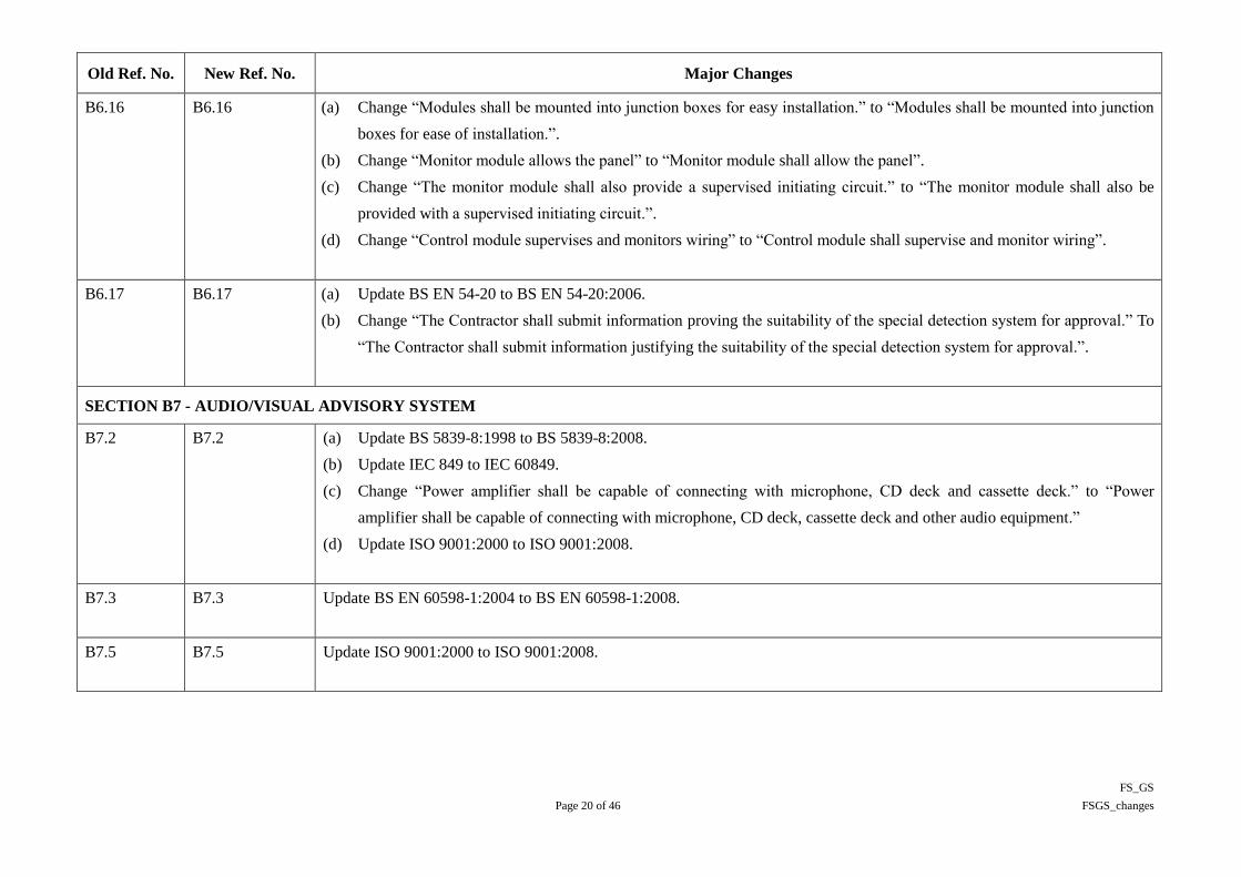
B6.16 B6.16 (a) Change “Modules shall be mounted into junction boxes for easy installation.” to “Modules shall be mounted into junction
boxes for ease of installation.”.
(b) Change “Monitor module allows the panel” to “Monitor module shall allow the panel”.
(c) Change “The monitor module shall also provide a supervised initiating circuit.” to “The monitor module shall also be
provided with a supervised initiating circuit.”.
(d) Change “Control module supervises and monitors wiring” to “Control module shall supervise and monitor wiring”.
B6.17 B6.17 (a) Update BS EN 54-20 to BS EN 54-20:2006.
(b) Change “The Contractor shall submit information proving the suitability of the special detection system for approval.” To
“The Contractor shall submit information justifying the suitability of the special detection system for approval.”.
SECTION B7 - AUDIO/VISUAL ADVISORY SYSTEM
B7.2 B7.2 (a) Update BS 5839-8:1998 to BS 5839-8:2008.
(b) Update IEC 849 to IEC 60849.
(c) Change “Power amplifier shall be capable of connecting with microphone, CD deck and cassette deck.” to “Power
amplifier shall be capable of connecting with microphone, CD deck, cassette deck and other audio equipment.”
(d) Update ISO 9001:2000 to ISO 9001:2008.
B7.3 B7.3 Update BS EN 60598-1:2004 to BS EN 60598-1:2008.
B7.5 B7.5 Update ISO 9001:2000 to ISO 9001:2008.
FS_GS
Page 21 of 46 FSGS_changes
Old Ref. No. New Ref. No. Major Changes
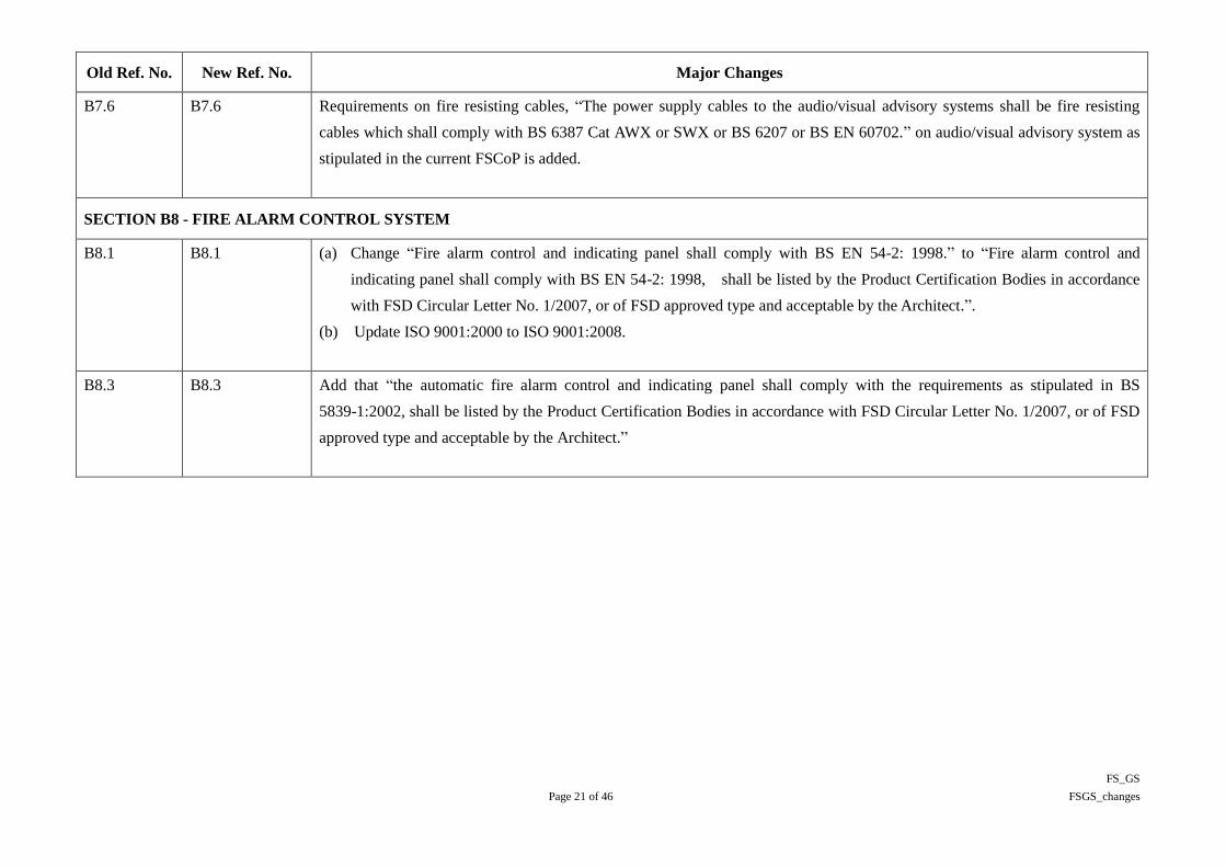
B7.6 B7.6 Requirements on fire resisting cables, “The power supply cables to the audio/visual advisory systems shall be fire resisting
cables which shall comply with BS 6387 Cat AWX or SWX or BS 6207 or BS EN 60702.” on audio/visual advisory system as
stipulated in the current FSCoP is added.
SECTION B8 - FIRE ALARM CONTROL SYSTEM
B8.1 B8.1 (a) Change “Fire alarm control and indicating panel shall comply with BS EN 54-2: 1998.” to “Fire alarm control and
indicating panel shall comply with BS EN 54-2: 1998, shall be listed by the Product Certification Bodies in accordance
with FSD Circular Letter No. 1/2007, or of FSD approved type and acceptable by the Architect.”.
(b) Update ISO 9001:2000 to ISO 9001:2008.
B8.3 B8.3 Add that “the automatic fire alarm control and indicating panel shall comply with the requirements as stipulated in BS
5839-1:2002, shall be listed by the Product Certification Bodies in accordance with FSD Circular Letter No. 1/2007, or of FSD
approved type and acceptable by the Architect.”

FS_GS
Page 22 of 46 FSGS_changes
Old Ref. No. New Ref. No. Major Changes
B8.5 B8.5 (a) Add that “the panel shall comply with the requirements as stipulated in BS 5839-1:2002 shall be listed by the Product
Certification Bodies in accordance with FSD Circular Letter No. 1/2007, or of FSD approved type and acceptable by the
Architect.”
(b) Change “in Sections B8.2 and B8.3” to “in Clauses B8.2 and B8.3”.
(c) Change “provide all power necessary for the devices connected to it and built-in the panel.” to “provide power necessary
for the devices connected to it and lodged in the panel.”
(d) Update ISO 9001:2000 to ISO 9001:2008.
(e) Add that a maintenance system or tool kits for scanning and reporting of situations and conditions of all devices, modules
and control loops connected to the fire alarm control and indicating panel to be provided. The scanning report can be
either printed by event printer or exported in an electronic format to be opened by commonly used computer software
available in the market. Such a system or tool kits can be either built-in type or external type.
B8.7 B8.7 Change “approved by LPCB or similar widely recognised independent regulatory body” to “approved by the relevant widely
recognised independent regulatory body”.
B8.8 B8.8 (a) Relocate “The Contractor shall also supply and install all conduit works for the fire alarm direct link and associated
telephone point.” from last sentence to place before the description on direct link charges.
(b) Change “to substitute the fire alarm direct link up to the date of the completion of the fire alarm direct link.” to “to
substitute the fire alarm direct link up to the date of the completion of the fire alarm direct link and to the satisfaction of
the Architect.”.
B8.9 B8.9 Delete the phrase “unless otherwise specified”.

FS_GS
Page 23 of 46 FSGS_changes
Old Ref. No. New Ref. No. Major Changes
B8.10 B8.10 (a) Change “The exact rated capacity shall be designed by the Contractor to supply a constant voltage and current for the
combined standing load and alarm load.” to “The rated capacity of the battery system shall be adequately allowed for by
the Contractor to supply a constant voltage and current for the combined standing load and alarm load in all situations.”.
(b) Change “less than 10AH.” to “less than 10 Ah.”.
(c) Change “D.C. output smoothed by a D.C. filter” to “D.C. output smoothed out by a D.C. filter”.
(d) Update ISO 9001:2000 to ISO 9001:2008.
(e) Change “Protection class of the cabinet shall not be less than IP 52 for indoors and IP65 for outdoor application.” to
“Adequate ventilation inside the cabinet shall be provided. Protection class of the cabinet shall not be less than IP 32 for
indoors and weatherproof for outdoor application.”.
(f) Change “If approved materials other than No. 1.4401 stainless steel is used, the entire enclosure surface shall be applied
with chemical rust inhibitor, rust resisting primer coat and top coat to give maximum corrosion protection.” to “If material
other than No. 1.4401 stainless steel is approved to be used, the entire enclosure surface shall be applied with chemical
rust inhibitor, rust resisting primer coat and top coat to give maximum corrosion protection, to the satisfaction of the
Architect.”.
(g) Change “A lower ventilated compartment inside the cabinet provides adequate space for accommodation of the storage
battery bank and ventilation.” to “A lower ventilated compartment inside the cabinet shall provide adequate space for
accommodation of the storage battery bank and ventilation.”.
B8.13 B8.13 (a) Change “The computer system is used” to “The computer system shall be used”.
(b) Change “Web-based computer software is preferred” to “Web-based computer software shall be preferred”.
SECTION B9 - ELECTRICAL INSTALLATION

FS_GS
Page 24 of 46 FSGS_changes
Old Ref. No. New Ref. No. Major Changes
B9.2 B9.2 (a) Change “All electrical equipment shall be rated for continuous duties at designed capacity.” to “All electrical equipment
shall be rated for continuous duties at designed capacity and operating conditions.”.
(b) Change “….. they are not susceptible to external electrical and magnetic interference as well as to supply harmonics ……”
to “….. they are not susceptible to external electrical and magnetic interference which includes but not limits to supply
interruption or voltage dip as well as to supply harmonics ……”.
B9.3 B9.3 (a) Change “All equipment and installations shall be sized with continuous ratings at the designed duties” to “All equipment
and installations shall be sized with continuous ratings at the designed duties and operating conditions”.
(b) Add “To cope with the possible interruption of the electrical power supply and/or the fluctuation of frequency or voltage
value outside the acceptable range specified above, all equipment and installations shall be able to ride through and
function properly on any unavoidable disturbance to the European Standard EN 50160: 2007.
All equipment and installations shall also comply with Semiconductor Equipment and Materials International (SEMI) F47,
IEC 61000-4-11: 2004 and IEC 61000-4-34: 2005 on voltage dip ride-through capability.” below the last paragraph.
B9.5 B9.5 Replace “LPC Rules for AFA Installations” with “BS 5839-1:2002”.

FS_GS
Page 25 of 46 FSGS_changes
Old Ref. No. New Ref. No. Major Changes
B9.8 B9.8 (a) Change “Identification of conductors and cables on LV power circuits shall be in accordance with the New Cable Colour
Code for Fixed Electrical Installations : Installation Guides published by Electrical and Mechanical Services Department
and as specified in the General Electrical Specification.” to “Identification colour codes of conductors and cables on LV
power circuits shall be in accordance with the current requirements and all subsequent amendments stipulated in the Code
of Practice for the Electricity (Wiring) Regulations issued by the Electrical and Mechanical Services Department and as
specified in the General Electrical Specification.”.
(b) Update BS 7671:2001 to BS 7671:2008.
(c) Add standard BS 5839-1:2002 in addition to BS 7671:2008.
(d) Change “Banding by means of paint will be acceptable where this can be carried out permanently and effectively.” to
“Banding by means of paint will be acceptable only where this can be carried out permanently and effectively.”.
B9.9 B9.9 (a) Change “Unless otherwise specified or approved by the Architect, fire resistant cables used for Fire Service Installation
shall be of low smoke zero halogen type and shall comply with all the following standards :” to “Unless otherwise
specified or approved by the Architect, fire resistant cables used for Fire Service Installation shall be of low smoke zero
halogen type and shall be in full compliance with the requirements of FSD. Fire resistance cables shall also comply with
the following standards :”.
(b) Update BS 7629-1:1997 to BS 7629-1:2008.
(c) Add standards IEC 60702-1:2002 & EN 60702-1:2002 for mineral insulated copper cables in addition to BS EN
60702-1:2002.
B9.10 and
B9.13
B9.10 and
B9.13
For products specified to be manufactured to ISO 9001, amend the requirement to “product shall be manufactured with ISO
9001 or manufactured by a manufacturer certified by ISO 9001 quality system” to reflect that some manufacturers obtained
ISO 9001 for the organizations but not the product itself.

FS_GS
Page 26 of 46 FSGS_changes
Old Ref. No. New Ref. No. Major Changes
B9.11 B9.11 Delete the phrase “unless otherwise specified” from the 1st paragraph.
B9.12 B9.12 Delete the phrase “unless otherwise specified” from the 2nd
paragraph.
B9.14 B9.14 (a) Add “LED lamps of approved type, size, brightness and colour shall be used for all exit signs for energy saving purpose.”.
(b) Change “LED lamps of approved size, brightness and colour” to “LED lamps of approved type, size, brightness and
colour”.
(c) Add “All LED lamps used shall comply with General Electrical Specification.”
SECTION B10 - PORTABLE HAND-OPERATED APPROVED APPLIANCES
B10.1 B10.1 (a) Change “Portable hand-operated approved appliances shall comply with FSDCoP and where applicable BS 5306-3: 2003.”
to “Portable hand-operated approved appliances shall comply with FSDCoP and Fire Protection Notice No. 11 and where
applicable BS 5306-3: 2009.”.
(b) Change “Remote monitoring facilities or theft stopper shall be supplied and installed where specified which will be
energised when the appliance is lifted up or removed.” to “Remote monitoring unit and remote alarm panel detailed in
Clause B10.5 below shall be supplied and installed where specified which shall be energised when the appliance is lifted
up or removed. The unit shall also monitor the condition of the portable hand-operated approved appliance.”.
(c) Add “The cabinet shall be of robust and weather-proof design to the acceptance of the FSD and the Architect. Its design
and construction shall ensure the ready access and taking out from the cabinet, and replacing back after use, the portable
appliance easily under all circumstances. Suitably sized and easily identifiable labels/wordings shall be fixed or engraved
permanently on the cabinet to enable users to locate the portable appliance readily, to the satisfaction of the FSD and
Architect.”
FS_GS
Page 27 of 46 FSGS_changes
Old Ref. No. New Ref. No. Major Changes
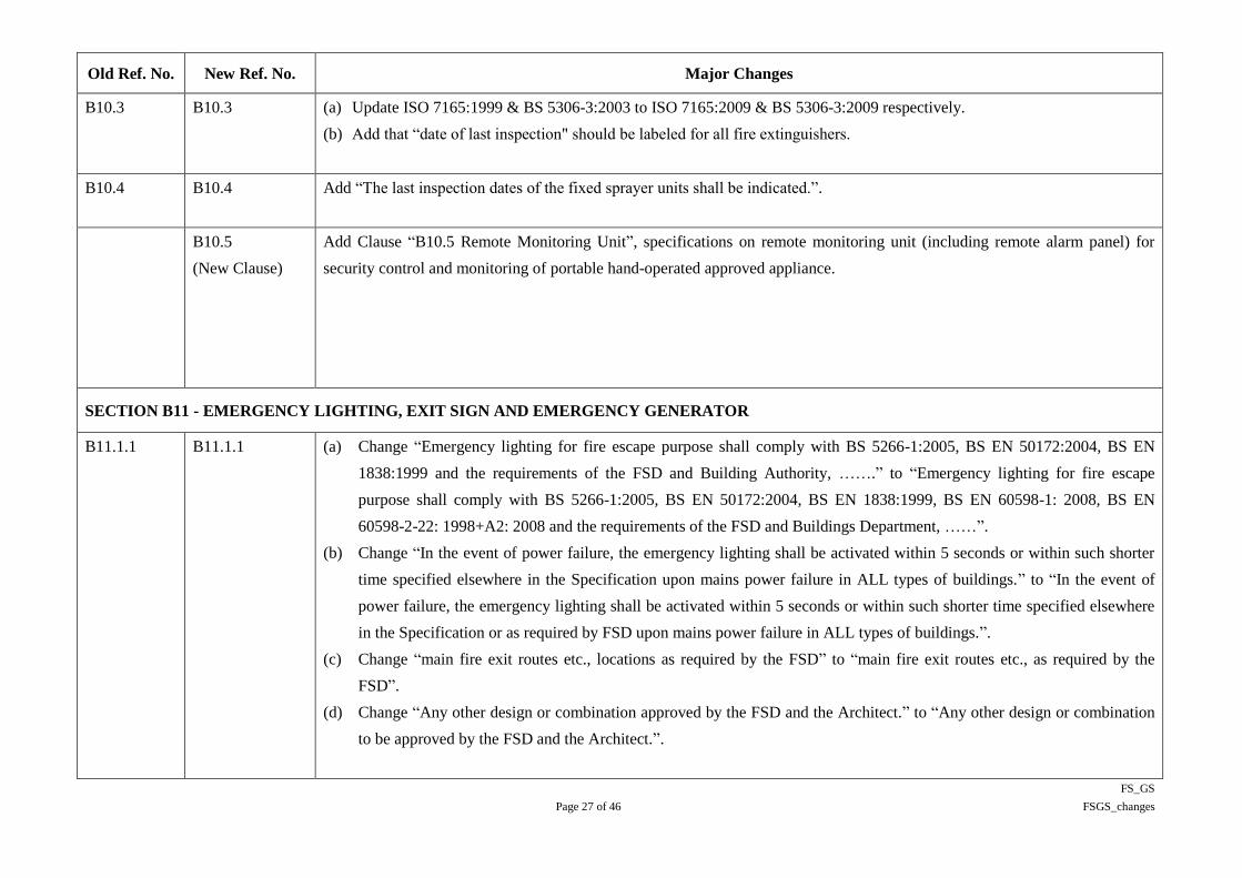
B10.3 B10.3 (a) Update ISO 7165:1999 & BS 5306-3:2003 to ISO 7165:2009 & BS 5306-3:2009 respectively.
(b) Add that “date of last inspection" should be labeled for all fire extinguishers.
B10.4 B10.4 Add “The last inspection dates of the fixed sprayer units shall be indicated.”.
B10.5
(New Clause)
Add Clause “B10.5 Remote Monitoring Unit”, specifications on remote monitoring unit (including remote alarm panel) for
security control and monitoring of portable hand-operated approved appliance.
SECTION B11 - EMERGENCY LIGHTING, EXIT SIGN AND EMERGENCY GENERATOR
B11.1.1 B11.1.1 (a) Change “Emergency lighting for fire escape purpose shall comply with BS 5266-1:2005, BS EN 50172:2004, BS EN
1838:1999 and the requirements of the FSD and Building Authority, …….” to “Emergency lighting for fire escape
purpose shall comply with BS 5266-1:2005, BS EN 50172:2004, BS EN 1838:1999, BS EN 60598-1: 2008, BS EN
60598-2-22: 1998+A2: 2008 and the requirements of the FSD and Buildings Department, ……”.
(b) Change “In the event of power failure, the emergency lighting shall be activated within 5 seconds or within such shorter
time specified elsewhere in the Specification upon mains power failure in ALL types of buildings.” to “In the event of
power failure, the emergency lighting shall be activated within 5 seconds or within such shorter time specified elsewhere
in the Specification or as required by FSD upon mains power failure in ALL types of buildings.”.
(c) Change “main fire exit routes etc., locations as required by the FSD” to “main fire exit routes etc., as required by the
FSD”.
(d) Change “Any other design or combination approved by the FSD and the Architect.” to “Any other design or combination
to be approved by the FSD and the Architect.”.

FS_GS
Page 28 of 46 FSGS_changes
Old Ref. No. New Ref. No. Major Changes
B11.1.2 B11.1.2 (a) Update BS EN 60598-2-22: 1999 to BS EN 60598-2-22: 1998+A2:2008.
(b) Change “For each enclosed space required to have emergency lighting, there shall be not less than one emergency
luminaire unless otherwise approved.” to “For each enclosed space required to have emergency lighting, the minimum
number of emergency luminaires shall follow the requirements of FSDCoP, or as specified in the Specification or
Drawings, whichever is the larger unless otherwise accepted by the FSD. In any case, there shall be not less than one
emergency luminaire in each of such enclosed spaces.”.
(c) Add that Emergency luminaires shall be capable of operating satisfactorily in the emergency mode at an ambient
temperature of 70oC for at least 1 hour, in according to BS EN 60598-2-22:1998+A2:2008, or, at least half of its rated
duration, whichever is a longer period.
B11.1.3 B11.1.3 (a) Change “or incorporate in it a device for charging the battery” to “or incorporated in it a device for charging the battery”.
(b) Change “visible in normal use which shows the following conditions: -” to “visible in normal use which shall show the
following conditions: -”.
(c) Change “The batteries shall have ample capacity to maintain the output of the emergency luminaires for a period
complying with FSDCoP and BS 5266-1:2005” to “The batteries shall have ample capacity to maintain the output of the
emergency luminaires for a period complying with FSDCoP and BS 5266-1:2005, BS EN 1838:1999”.

FS_GS
Page 29 of 46 FSGS_changes
Old Ref. No. New Ref. No. Major Changes
B11.1.4 B11.1.4 (a) Change “Unless otherwise specified, AC emergency luminaires shall be used. The central battery power supply system
shall be capable of providing AC power supply to the emergency luminaires.” to “AC emergency luminaires shall be used.
The central battery power supply system shall be capable of providing AC power supply to the emergency luminaires.”.
(b) Replace “LPC Rules for AFA Installations” with “BS 5839-1: 2002”.
(c) For products specified to be manufactured to ISO 9001, amend the requirement to “product shall be manufactured with
ISO 9001 or manufactured by manufacturer certified by ISO 9001 quality system” to reflect that some manufacturers
obtained ISO 9001 for the organizations but not the product itself.
(d) Update ISO 9001:2000 to ISO 9001:2008.
(e) Update EN 50091-2:1995 to BS EN 62040-2:2006.
(f) Change “The battery system for centrally supplied emergency luminaire shall have ample capacity to maintain the output
of all connected emergency luminaires for a period complying with FSDCoP and BS 5266-1:2005,” to “The battery
system for centrally supplied emergency luminaire shall have ample capacity to maintain the output of all connected
emergency luminaires for a period complying with FSDCoP and BS 5266-1:2005, BS EN 1838:1999,”.
(g) Change “The battery system shall be designed to operate at voltage not less than 24V and not more than 120V DC.” to
“The battery system shall be designed to operate at a voltage not less than 24V and not more than 120V DC.”.
B11.1.6 B11.1.6 (a) Update “LPC Rules for AFA Installations” to “BS 5839-1: 2002”.
(b) Change “Transformers for charging the batteries shall comply with relevant requirements stipulated in IEC 60742.” To
“Transformers for charging the batteries shall comply with relevant requirements stipulated in IEC 60742 or BS EN
61558-2 Series.”.
(c) Update “BS EN 60598-2.22” to “BS EN 60598-2-22:1998+ A2:2008”.

FS_GS
Page 30 of 46 FSGS_changes
Old Ref. No. New Ref. No. Major Changes
B11.1.7 B11.1.7 (a) Delete the phrase “unless otherwise specified” from the 3rd
paragraph.
(b) Change “modify the programs of the CMTL system without affecting system operation.” to “modify the programmes of
the CMTL system without affecting system operation.”.
B11.1.8 B11.1.8 Update BS 7671:2000 to BS 7671:2008.
B11.1.9 B11.1.9 (a) Change “either by installation in a separation conduit” to “either by installation in a separation steel conduit”.
(b) Change “and continuous partition of non-combustible material. Any metal partition shall be electrically earthed to BS
7671:2001.” to “and continuous partition of steel or other approved non- combustible material. All metal parts and
partitions shall be electrically earthed to BS 7671:2008.”.
B11.1.11 B11.1.11 (a) Change “do not cause electromagnetic interference” to “shall not cause electromagnetic interference”.
(b) Add “When LED luminaires are used for emergency lighting, it shall comply with the radiated disturbance limit
requirements that specified in the CISPR 15 standard on “Limit and methods of measurement of radio disturbance
characteristics of electrical lighting and similar equipment” issued by the International Electrotechnical Commission
(IEC) and all relevant requirements of OFTA.”.
B11.1.12 B11.1.12 (a) Change “….. by others taking the role as a registered fire services installation contractor for them.” to “….. by others
taking the role as a registered fire service installation contractor for them.”.
(b) Change “ …… shall be limited to those required by the FSD and the Building Authority ……..” to “ …… shall be limited
to those required by the FSD and the Buildings Department ……..”.

FS_GS
Page 31 of 46 FSGS_changes
Old Ref. No. New Ref. No. Major Changes
B11.2 B11.2 (a) Update “BS EN 60598-1: 2004” to “BS EN 60598-1: 2008”.
(b) Delete the phrase “unless otherwise specified” from the 1st paragraph.
(c) Add “LED lamps of approved type, size, brightness and colour shall be used for all exit signs for energy saving purpose,
as specified in Clause B9.14.”.
(d) Requirements of FSD Circular 5/2008, such as graphic design and size, on Exit Sign are added.
(e) Change “Colour contrast for translucent surrounds to lettering shall be either one of the following combinations” to
“Colour contrast for translucent surrounds to lettering/graphical symbol shall be either one of the following
combinations”.
(f) Change “throughout the same building.” “throughout the same development.”.
(g) Change “The colour shall not deteriorate or become faint throughout the service life and lasts for at least ten years.” to
“The colour shall not deteriorate or become faint throughout the service life and shall last for at least ten years.”.
(h) Change “fluorescent exit sign in smoke condition” to “LED exit sign in smoke condition”.
(i) Change “The exit sign shall be capable of operating satisfactorily in the emergency mode at an ambient temperature of
70oC for at least half of the rated duration” to “The exit sign shall be capable of operating satisfactorily in the emergency
mode at an ambient temperature of 70oC for at least half of the rated duration or at least 1 hour in according to BS EN
60598-2-22:1990+A2:2008, whichever is longer,”.
(j) Change “when operated at ambient temperature” to “when operated at an ambient temperature”.
(k) Change “liability to the building occupants, workers, public visitors” to “liability to the building occupants, workers, and
public visitors”.
(l) Change “The number of lamps for each internally illuminated sign” to “The number of LED lamps for each internally
illuminated sign”.

FS_GS
Page 32 of 46 FSGS_changes
Old Ref. No. New Ref. No. Major Changes
(m) Delete “Where fluorescent lamp is used as the light source for exit sign, energy saving T5 fluorescent lamps or fluorescent
lamps demonstrated to be equivalent or better in terms of functions and performance shall be provided. Where LED
emitter is used as the light source for exit sign,”.
(n) Change “each LED emitter” to “each LED lamp”.
(o) Add “LED luminaires in exit sign shall comply with the radiated disturbance limit requirements that specified in the
CISPR 15 standard on “Limit and methods of measurement of radio disturbance characteristics of electrical lighting and
similar equipment” issued by the International Electrotechnical Commission (IEC) and all relevant requirements of
OFTA.”.
B11.3 B11.3 (a) Change “….. by others taking the role as a registered fire services installation contractor for it.” to “….. by others taking
the role as a registered fire service installation contractor for it.”.
(b) Change the 10th paragraph, “….. supplying other essential electrical load unless otherwise approved.” to “….. supplying
other essential electrical loads unless otherwise approved.”.
(c) Change the 11th paragraph, “non-fire service electrical load connected” to “non-fire service electrical loads connected”.
SECTION B12 - MECHANICAL, SPECIAL AND RELATED FIRE SERVICE INSTALLATIONS

FS_GS
Page 33 of 46 FSGS_changes
Old Ref. No. New Ref. No. Major Changes
B12.1 B12.1 (a) Change “ …..shall be carried out by a contractor registered both with the FSD and with the Building Authority complying
with the statutory regulations.” to “ …..shall be carried out by a contractor registered both with the FSD and with the
Buildings Department complying with the statutory regulations.”.
(b) Add more specific requirements on RPEs that they shall be in Fire, Building Services, Mechanical or Electrical disciplines
and have at least 3 years relevant design experience.
(c) Add “The professional status and qualifications of the Registered Professional Engineer shall also be acceptable by FSD
and the Architect.”.
(d) Change “….. by others taking the role as a registered fire services installation contractor for it.” to “….. by others taking
the role as a registered fire service installation contractor for it.”.
B12.2 B12.2 Add that the VAC control system shall be “reliable in operation and comply with all the related requirements of FSD”, in
addition to be of fail-safe design.
B12.3 B12.3 Delete the phrase “unless otherwise specified” from the Clause (d).
B12.4 B12.4 (a) Change “The Contractor shall ensure that all system and installation are fail-safe to maintain free passage of smoke” to
“The Contractor shall ensure that all systems and installations are fail-safe, reliable in operation and meeting with all the
related requirements of FSD, as to maintain free passage of smoke”.
(b) Delete the phrase “unless otherwise specified” from the Clauses (c) and (e).
B12.5 B12.5 (a) Delete the phrase “unless otherwise specified” from the 1st paragraph.
(b) Change “The unit shall be of fail-safe design such that the damper shall be released at no power supply.” to “The unit shall
be of fail-safe design such that the damper shall be released at no power supply, and shall be reliable in operation and
meeting with all the related requirements of FSD.”.

FS_GS
Page 34 of 46 FSGS_changes
Old Ref. No. New Ref. No. Major Changes
B12.6 B12.6 (a) Change “The engineer employed shall be a Registered Professional Engineer in Hong Kong under CAP 409 in building
services discipline (or equivalent approved professional qualification) specialised in fire service installation design.” to
“The engineer employed shall be a Registered Professional Engineer in Hong Kong under CAP 409 in fire, building
services, mechanical or electrical discipline (or equivalent approved professional qualification) with proof of experience of
at least 3 years specialised in fire service installation design.”.
(b) Add “The professional status and qualifications of the Registered Professional Engineer shall also be acceptable by FSD
and the Architect.”.
(c) Change “For equipment model that has not been accepted by the FSD before, the Contractor shall obtain the endorsement
of the FSD and the Architect before ordering.” to “All equipment used shall be of FSD approved type or shall be listed by
the Product Certification Bodies in accordance with FSD Circular Letter No. 1/2007. For equipment model that has not
been accepted by the FSD before or has not been listed by the Product Certification Bodies, the Contractor shall obtain the
endorsement of the FSD and the Architect before ordering.”.
(d) Change “For special equipment that has not been accepted by the FSD before, the Contractor shall employ Registered
Professional Engineer in Hong Kong under CAP 409 in approved discipline to certify the performance and functioning of
the special equipment and obtain the endorsement of the FSD and the Architect.” to “For special equipment that has not
been accepted by the FSD before, the Contractor shall employ a Registered Professional Engineer in Hong Kong under
CAP 409 with proof of experience of at least 3 years in the relevant and approved discipline to certify the performance and
functioning of the special equipment and obtain the endorsement of the FSD and the Architect.”.

FS_GS
Page 35 of 46 FSGS_changes
Old Ref. No. New Ref. No. Major Changes
SECTION B13 - MISCELLANEOUS
B13.1 B13.1 (a) Add that all labels should meet statutory requirements wherever applicable.
(b) Change the term „storage batteries‟ in the last paragraph to „rechargeable batteries‟.
(c) In the last paragraph, add that cabinet for storing the portable handset equipment shall be lockable cabinet of at least
1.6mm thick stainless steel to BS EN 10088-1: 2005 No. 1.4401 and of robust construction to the satisfaction of the
Architect.
B13.3 B13.3 (a) Add “The volatile organic compound (VOC) content, in grams per litre, of all paint and primer shall not exceed the
prescribed limits set by the EPD and those listed in the Air Pollution (Volatile Organic Compounds) Regulation.”.
(b) Change “The volatile organic compound (VOC) content, in grams per litre, of all paint applied on surfaces of fire service
installation and any installations/equipment ……” to “In addition, the VOC content, in grams per litre, of all paint applied
on surfaces of fire service installation and any installations/equipment ……”.
(c) Change “The testing method of the VOC content of paint shall be determined by the US EPA Method 24.” to “The testing
method of the VOC content of paint shall be determined by the US EPA Method 24 or other methods acceptable to EPD
and the Architect.”.
B13.4 B13.4 Add that the cabinet for housing the spares and tools shall be of at least 1.6mm thick stainless steel to BS EN 10088-1: 2005
No. 1.4401 and robust in construction to the satisfaction of the Architect.
B13.9 B13.9 Add that the schematic diagrams and key layout drawings provided in major plant rooms and fire service control rooms shall be
of adequate sizes and clearly presented to the satisfaction of the Architect.

FS_GS
Page 36 of 46 FSGS_changes
Old Ref. No. New Ref. No. Major Changes
PART C - PERFORMANCE BASED FIRE ENGINEERING
SECTION C1 - PERFORMANCE BASED FIRE ENGINEERING

FS_GS
Page 37 of 46 FSGS_changes
Old Ref. No. New Ref. No. Major Changes
C1.1 C1.1 (a) Replace “performance based fire engineering” with “PBFE”.
(b) To provide more specific requirements on RPEs that they shall be in Building Services, Electrical, Mechanical or Fire
discipline and have at least 3 years relevant FSI design and studies experience.
(c) Change “and have adequate knowledge of Buildings Regulations in Hong Kong” to “and have adequate knowledge of
Building Regulations in Hong Kong”.
(d) Add “The professional status and qualifications of the Registered Professional Engineer shall also be acceptable by FSD
and the Architect.”.
(e) Add “The Registered Professional Engineer employed for works on PBFE shall not be the professional independent
checking engineer employed as required in Clause C1.5 or the commissioning engineer as required in Clause D1.1.2 for
any part of the Works.”.
C1.2 C1.2 (a) Change “recognised fire engineering standards, codes and guides acceptable to the FSD and Building Authority” to
“recognised fire engineering standards, codes and guides acceptable to the FSD and Buildings Department”.
(b) Add BS 9999: 2008, Code of practice for fire safety in the design, management and use of buildings.
(c) Add PAS 79: 2007, Fire risk assessment – Guidance and a recommended methodology.
(d) Add PAS 911: 2007, Fire strategies – Guidance and framework for their formulation.
(e) Update NFPA 101:2006 to NFPA 101:2009.
(f) Update NFPA 101A:2007 to NFPA 101A:2010.
(g) Add NFPA 5000: 2009(h) Change “shall obtain the agreement of the FSD and Building Authority and the approval of the
Architect” to “shall obtain the agreement of the FSD and Buildings Department and the approval of the Architect”.
(i) Change “The Contractor shall also comply with the latest codes, guides, manuals and other requirements on PBFE issued
by the FSD and Building Authority.” to “The Contractor shall also comply with the latest codes, guides, manuals and other
requirements on PBFE issued by the FSD and Buildings Department.”.

FS_GS
Page 38 of 46 FSGS_changes
Old Ref. No. New Ref. No. Major Changes
C1.3 C1.3 Change “All calculation and computed results shall be checked and endorsed by the competent and experienced professional
engineer(s) employed by the Contractor for the PBFE in Clause C1.1.” to “All calculation and computed results shall be
checked and endorsed by the competent and experienced professional engineer(s) employed by the Contractor, as detailed in
Clause C1.1, for the PBFE.”.
C1.5 C1.5 (a) To provide more specific requirements on independent checking engineers that they shall be RPEs in Building Services,
Mechanical, Electrical or Fire discipline and have at least 3 years relevant FSI design and studies experience.
(b) Replace “performance based fire engineering” with “PBFE”.
(c) Change “and have adequate knowledge of Buildings Regulations in Hong Kong” to “and have adequate knowledge of
Building Regulations in Hong Kong”.
(d) Add “The professional status and qualifications of the independent checking engineer shall also be acceptable by the FSD
and the Architect.”.
(e) Add “The professional independent checking engineer employed shall be neutral, and independent and cannot be an
employee of either the Employer or Contractor or any Specialist Sub-contractor who may be engaged for the execution of
any part of the Works and shall not have any actual conflict of interest. He shall not be the professional engineer employed
for works on PBFE as required in Clause C1.1 or the commissioning engineer as required in Clause D1.1.2 for any part of
the Works.”.

FS_GS
Page 39 of 46 FSGS_changes
Old Ref. No. New Ref. No. Major Changes
C1.6 C1.6 (a) Change “The Contractor shall obtain the comments and approvals from the FSD, Building Authority, ……” to “The
Contractor shall obtain the comments and approvals from the FSD, Buildings Department, ……”.
(b) Change “ …… the Contractor shall submit and obtain the approval of relevant authorities such as the FSD and Building
Authority on all the results, …. ” to “ …… the Contractor shall submit and obtain the approval of relevant authorities
such as the FSD and Buildings Department on all the results, …. ”.
(c) Change “ …. the Contractor shall submit preliminary report to seek comments from the Architect, the FSD and the
Building Authority …… ” to “ …. the Contractor shall submit preliminary report to seek comments from the Architect,
the FSD and the Buildings Department …… ”.
C1.7 C1.7 Change “ ….. additional fire safety measures to the approval of the Architect, the FSD and Building Authority …… ” to “ …..
additional fire safety measures to the approval of the Architect, the FSD and Buildings Department …… ”.
C1.9 C1.9 Delete the phrase “unless otherwise specified” from the 2nd
paragraph.
PART D - INSPECTION, TESTING AND COMMISSIONING
SECTION D1 - INSPECTION, COMMISSIONING AND ACCEPTANCE TEST

FS_GS
Page 40 of 46 FSGS_changes
Old Ref. No. New Ref. No. Major Changes
D1.1.2 D1.1.2 (a) Add that the commissioning engineer in charge (CEIC) shall be RPE in Building Services, Electrical, Mechanical or Fire
discipline and have at least 3 years on-site experience in similar type and scale of testing and commissioning works.
(b) Add “The professional status and qualifications of the CEIC shall also be acceptable by FSD and the Architect.”.
(c) Add “The CEIC employed shall not be the professional engineer employed for works on PBFE as required in Clause C1.1
or the professional independent checking engineer employed in Clause C1.5 for any part of the Works.”.
D1.1.9 D1.1.9 Change “Type-test for equipment shall be carried out at the manufacturers‟ works or elsewhere appropriate” to “Type-test for
equipment shall be carried out at the manufacturers‟ works or elsewhere as appropriate”.
D1.1.11 D1.1.11 Change “Testing and commissioning shall be properly checked and certified by Contractor‟s CEIC” to “Testing and
commissioning shall be properly checked and certified by the Contractor‟s CEIC”.
D1.2 D1.2 Change “The Contractor shall program for a progressive testing” to “The Contractor shall programme for a progressive testing”.
D1.2.2 D1.2.2 Change “any consequential losses such as the re-program of work/acceleration of work” to “any consequential losses such as
the re-programme of work/acceleration of work”.
D1.3 D1.3 Change “An actual water discharge test shall be performed on the drencher/deluge/water spray/water mist system” to “An
actual water discharge test shall be performed on the extended coverage sprinkler system/drencher/deluge/water spray/water
mist system”.

FS_GS
Page 41 of 46 FSGS_changes
Old Ref. No. New Ref. No. Major Changes
D1.4 D1.4 (a) Change “Such test shall deemed to be successful only if” to “Such test shall be deemed to be successful only if”.
(b) Change “The Contractor shall submit a copy of the application document to the Architect for record.” to “The Contractor
shall submit a return copy of the application document to the Architect for record.”.
(c) Change “The fire alarm direct link shall be tested after connection.” to “The states of “Normal”, “Fire” and “Out of order”
of fire alarm direct link shall be tested after connection.”.
D1.5 D1.5 Add “D.G. Certificate of cylinder shall be submitted before the cylinders are delivered to site. Related documents including
charging certificates and etc. shall be submitted for record.”.
D1.7 D1.7 For emergency generator tests, add “For supply system with more than one automatically changeover devices, each
automatically changeover device shall be tested individually to verify the automatical start function of emergency generators.”.
D1.8 D1.8 Change “The engineer employed shall be a Registered Professional Engineer in Hong Kong under CAP 409 in building
services or mechanical discipline or equivalent approved professional qualification.” to “The engineer employed shall be a
Registered Professional Engineer in Hong Kong under CAP 409 in fire, building services, mechanical or electrical discipline
(or other equivalent approved professional qualifications) with proof of experience of at least 3 years in hot smoke test and fire
service installation works. The professional status and qualifications of the Registered Professional Engineer shall also be
acceptable by FSD and the Architect.”.

FS_GS
Page 42 of 46 FSGS_changes
Old Ref. No. New Ref. No. Major Changes
D1.8.1 D1.8.1 (a) Change “be approved by the Architect before such test(s) be commenced.” to “be approved by the Architect before such
test(s) is commenced.”.
(b) Add “All smoke extraction ducts located outside the compartment including concrete ducts or shafts and other
constructions shall be pressure tested. The pressure test of ductwork shall comply with DW/143 on “A Practical Guide to
Ductwork Leakage Testing” issued by the Heating & Ventilating Contractors‟ Association and all subsequent amendments.
The test records shall be submitted for record.”.
D1.8.3 D1.8.3 (a) Change “The Contractor shall prepare flowchart & working procedures for the hot smoke test” to “The Contractor shall
prepare flowchart and working procedures for the hot smoke test”.
(b) Change “and staff present in the test to aware that prolonged exposure to tracer smoke may cause irritation” to “and staff
present in the test to ensure that they are fully aware that prolonged exposure to tracer smoke may cause irritation”.
D1.13 D1.13 Change “The Contractor shall co-ordinate with relevant parties on the programme for carrying out such cleaning work shall
obtain the approval of the Architect especially when the occupants of the building may arrange fitting-out works.” to “The
Contractor shall co-ordinate with relevant parties on the programme for carrying out such cleaning work so as to ensure that the
cleaning work of detectors shall not be in conflict with all other activities such as fitting-out works to be carried out on Site.
The cleaning programme shall be to the approval of the Architect.”.
D1.14 D1.14 Change “The report shall be checked, verified, and endorsed by the CEIC and certified by a Registered Professional Engineer
in Hong Kong under CAP 409 in approved disciplines (or equivalent professional qualification) employed by the Contractor,
except when approved by the Architect for minor installations, the report shall be checked” to “The report shall be checked,
verified, and endorsed by the CEIC and certified by another Registered Professional Engineer of the same qualification and
requirements as CEIC that specified in Clause D1.1.2 employed by the Contractor, except when approved by the Architect for
minor installations when the report shall be checked”.

FS_GS
Page 43 of 46 FSGS_changes
Old Ref. No. New Ref. No. Major Changes
PART E - INSPECTION, ATTENDANCE, OPERATION AND MAINTENANCE DURING MAINTENANCE PERIOD
SECTION E1 - INSPECTION, ATTENDANCE, OPERATION, MAINTENANCE AND FINAL TESTING
E1.1 E1.1 (a) Change “addresses of the Contractor‟s English-speaking and Cantonese- speaking representatives to who services calls
should be directed.” to “addresses of the Contractor‟s English-speaking and Cantonese- speaking representatives that
services calls should be directed.”.
(b) Change “All materials and equipment reaching expiry date of service life shall be replaced.” to “All materials and
equipment reaching expiry date of service life shall be replaced by the Contractor.”.
(c) Change “The Contractor shall arrange necessary temporary facilities” to “The Contractor shall arrange all necessary
temporary facilities”.
(d) Add “All the inspections, attendance, operation, maintenance and testing of fire service installations shall follow all the
relevant FSD Requirements, and in addition the procedures and measures stipulated in FSD Circular Letter No. 3/2008 for
cases that involve the shutting down or isolation of installations, to the acceptance of the FSD and the Architect.”.
(e) Add “The Contractor shall also adopt the sprinkler subsidiary stop valves management system in accordance with the
requirements of FSD Circular Letter No. 4/2010 on the inspections, tests, operation, maintenance services and repair works
of sprinkler system.”.
(f) Change “The Contractor shall record all the details of operation: faults and corrective actions taken” to “The Contractor
shall record all the details of operation, such as, faults and corrective actions taken”.
(g) Change “carried out at any time unless the Architect has been notified and given approval.” to “carried out at any time
unless the Architect has been notified and approval given.”.
(h) Change “ …… the Maintenance Period complying with the requirements of the FSD/Building Authority ….. ” to “ ……
the Maintenance Period complying with the requirements of the FSD/Buildings Department ….. ”.

FS_GS
Page 44 of 46 FSGS_changes
Old Ref. No. New Ref. No. Major Changes
E1.2 E1.2 (a) Change “shall be repaired, test and then reinstated within 2 hours.” to “shall be repaired, tested and then reinstated within 2
hours.”.
(b) Change “carry out the remedial work following the agreed program and method” to “carry out the remedial work following
the agreed programme and method”.
(c) Add “The procedures and measures stipulated in FSD Circular Letter No. 3/2008 for cases that involve the shutting down
or isolation of installations shall be followed, to the acceptance of the FSD and the Architect.”.

FS_GS
Page 45 of 46 FSGS_changes
Old Ref. No. New Ref. No. Major Changes
E1.3 E1.3 (a) Change “to carry out tests, repairs, maintenance and adjustments.” to “to carry out all necessary tests, repairs, maintenance
and adjustments as relevant.”.
(b) Change “All environmentally sensitive devices, e.g. smoke and heat detectors, air filters at the end of the probes for duct
type detectors, electronic sensors, relay contacts, plug and socket contacts, printed circuit boards, edge connectors etc. shall
be inspected, cleaned, adjusted, tested and calibrated.” to “For environmentally sensitive devices, e.g. smoke and heat
detectors, air filters at the end of the probes for duct type detectors, electronic sensors, relay contacts, plug and socket
contacts, printed circuit boards, edge connectors etc. that required to be inspected, cleaned, adjusted, tested and calibrated
more frequently, the Contractor shall arrange corresponding visits, inspections, cleaning, adjustment, testing and
calibration in shorter time intervals, to the satisfaction of the Architect. For this purpose, the Contractor shall submit, in
according to the recommendations or instructions of manufacturers/ suppliers, the actual site conditions, and performance
requirements, a schedule of inspection, cleaning, adjustment, testing, and calibration of all installed devices within the
Maintenance Period to the Architect for approval.”.
(c) Add “For those panels with built-in maintenance system or tool kits as specified in Clause B8.5, the Contractor shall carry
out system scanning and checking at least once every 3 months. All problematic devices shall be repaired or replaced
immediately. Scanning report shall be submitted together with the routine quarterly report to the Architect.”.
(d) Change “During the visits, the following tests and checks shall be made:- A test sequence shall be carried out in
accordance with the manufacturer‟s instructions.” to “During each visit, a test sequence shall be carried out in accordance
with the manufacturer‟s instructions.”.
(e) Change “Test (c) and (d) will prove that all system alarms and relevant controls are operating correctly.” to “Test (c) and
(d) shall prove that all system alarms and relevant controls are operating correctly.”.
E1.14 E1.14 Change “Inspection, Testing And Maintenance Of Other Fire Service Installation” to “Inspection, Testing And Maintenance Of
Other Fire Service Installations”.
ANNEX I - LIST OF TECHNICAL STANDARDS AND QUALITY STANDARDS QUOTED IN THIS GENERAL SPECIFICATION

FS_GS
Page 46 of 46 FSGS_changes
Old Ref. No. New Ref. No. Major Changes
General update of all standards.
ANNEX II - STANDARDS AND REQUIREMENTS TO SATISFY FIRE SERVICES DEPARTMENT
1st Para. 1
st Para. Change “The fire services installation shall comply with the following standards and requirements as required by the Fire
Service Department unless otherwise approved by the Architect.” to “The fire service installations shall comply with the
following standards and requirements as required by the Fire Services Department unless otherwise approved by the
Architect.”.
b. Delete FOC and BS 5306-2 on sprinkler system because it is outdated.
c. b. Update the item as FSD Circular Letters No. 1/2009 and No. 3/2010 has superseded FSD Circular Letter No. 1/2002, and that
BS 5839: Part 1:1988 is replaced by BS 5839-1:2002 + A2:2008.
d. Delete the standard on FOC Rules on AFA Installations because it is outdated.
d. Add in NFPA 2001, 2008 Edition, Standard on Clean Agent Fire Extinguishing Systems.
e. Add in BS EN 1838:1999 – Lighting applications – Emergency lighting and BS 5266-1:2005, Emergency lighting – Part 1 :
Code of Practice for the emergency lighting of premises.

Corrigendum No. GSFS01 FS_GS
Page 1 of 188 FSGS_corrigendum
ARCHITECTURAL SERVICES DEPARTMENT
BUILDING SERVICES BRANCH
GENERAL SPECIFICATION FOR FIRE SERVICE INSTALLATION IN
GOVERNMENT BUILDINGS OF THE HONG KONG SPECIAL
ADMINISTRATIVE REGION
2007 EDITION
Corrigendum No. GSFS01
(December-2010) The following content and clauses are amended in the above General Specification.
Content
TABLE OF CONTENTS
PART A SCOPE AND GENERAL REQUIREMENTS
SECTION A4 DRAWINGS AND MANUALS
A4.1 Drawings in Electronic Format
A4.2 Installation Drawings
A4.2.1 Drawing Submission Schedule
A4.2.2 Size of Installation Drawings
A4.2.3 Contents of Installation Drawings
A4.2.4 Builder‟ s Work Drawings
A4.2.5 Manufacturer‟s Shop Drawings
A4.2.6 Drawings for Submission to Other Authority
(FSD/Gas Office/EMSD/WSD etc)
A4.3 As-built Drawings
A4.3.1 Submission of As-built Drawings
A4.3.2 Size of As-built Drawings
A4.3.3 Content of As-built Drawings
A4.3.4 Framed Drawings
A4.4 Operation and Maintenance (O&M) Manual and User
Manual
A4.4.1 General
A4.4.2 Checking and Approval
A4.4.3 Structure and Content of O&M Manual
A4.4.4 Structure and Content of User Manual
A4.4.5 Presentation
A4.5 Intellectual Property Rights
A4.6 Additional Requirements for Addressable System
A4.7 Checking Before Submission

Corrigendum No. GSFS01 FS_GS
Page 2 of 188 FSGS_corrigendum
PART B FIRE SERVICE INSTALLATION
SECTION B10 PORTABLE HAND-OPERATED APPROVED APPLIANCES
B10.5 Remote Monitoring Unit
PART E INSPECTION, ATTENDANCE, OPERATION AND
MAINTENANCE DURING MAINTENANCE PERIOD SECTION E1 INSPECTION, ATTENDANCE, OPERATION, MAINTENANCE,
REPAIR AND FINAL TESTING E1.14 Inspection, Testing And Maintenance Of Other Fire Service
Installations

Corrigendum No. GSFS01 FS_GS
Page 3 of 188 FSGS_corrigendum
Clauses
PART A - SCOPE AND GENERAL REQUIREMENTS
SECTION A1
SCOPE OF SPECIFICATION
A1.3.2 Abbreviations
ANSI American National Standards Institute
ASTM American Society for Testing and Materials
BS British Standards, including British Standard Specifications
and British Standard Codes of Practice, published by the
British Standards Institution
BSB Building Services Branch, Architectural Services Department
of the Hong Kong Special Administrative Region
BS EN European Standard adopted as British Standard
EE_TC Testing and Commissioning Procedure for Electrical
Installation in Government Buildings, Hong Kong, issued by
the Architectural Services Department, the HKSAR
EMSD Electrical and Mechanical Services Department of the Hong
Kong Special Administrative Region
FM Factory Mutual, USA.
FOC Fire Offices‟ Committee, UK.
FRC
Code of Practice for Fire Resisting Construction published by
the Buildings Department, the HKSAR
FRP Fire resistance period
FSD Fire Services Department of the Hong Kong Special
Administrative Region
FSDCoP Codes of Practice for Minimum Fire Service Installations and
Equipment and Inspection, Testing and Maintenance of
Installations and Equipment published by Fire Services
Department, the HKSAR
FS_TC Testing and Commissioning Procedure for Fire Service
Installation in Government Buildings, Hong Kong, issued by
the Architectural Services Department, the HKSAR

Corrigendum No. GSFS01 FS_GS
Page 4 of 188 FSGS_corrigendum
HKSAR Hong Kong Special Administrative Region
IEC International Electrotechnical Commission Publications
IEE Wiring
Regulations
Regulations for Electrical Installations (BS 7671: 2001)
published by the Institution of Electrical Engineers, UK
ISO International Operation for Standardization Publications
MoA Code of Practice for Means of Access for Firefighting and
Rescue published by the Buildings Department, the HKSAR
MoE Code of Practice for the Provision of Means of Escape In case
of Fire published by the Buildings Department, the HKSAR
NFPA National Fire Protection Association, USA
OFTA Office of the Telecommunications Authority of the Hong
Kong Special Administrative Region
LPC Loss Prevention Council, UK
LPCB Loss Prevention Certification Board, UK
PAS Publicly Available Specification published by the British
Standards Institution
PNxx Pressure Rating xx BAR at 23oC
PBFE Performance based fire engineering (or performance based
fire safety engineering or performance based fire protection
engineering) studies, approaches, analyses, assessment,
applications and/or similar works adopting fire engineering
principles
RFSI Related Fire Service Installation and shall include all fire
service installations in a building or project that are carried
out by others and not included in the Works under Fire
Service Installation, but they are required to be inspected and
accepted by the FSD on completion. Related Fire Service
Installation shall include, but not limited to, water supplies,
supply tanks, ring main systems, street hydrants, interfacing
signals between fire service system and various electrical and
mechanical systems, emergency generator, emergency
lighting, exit sign, pressurisation of staircases system, smoke
extraction system, and fixed automatically operated approved
appliances.
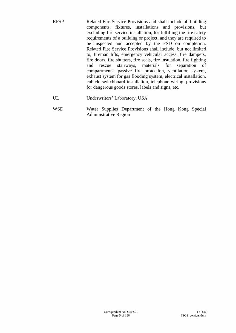
Corrigendum No. GSFS01 FS_GS
Page 5 of 188 FSGS_corrigendum
RFSP Related Fire Service Provisions and shall include all building
components, fixtures, installations and provisions, but
excluding fire service installation, for fulfilling the fire safety
requirements of a building or project, and they are required to
be inspected and accepted by the FSD on completion.
Related Fire Service Provisions shall include, but not limited
to, fireman lifts, emergency vehicular access, fire dampers,
fire doors, fire shutters, fire seals, fire insulation, fire fighting
and rescue stairways, materials for separation of
compartments, passive fire protection, ventilation system,
exhaust system for gas flooding system, electrical installation,
cubicle switchboard installation, telephone wiring, provisions
for dangerous goods stores, labels and signs, etc.
UL Underwriters‟ Laboratory, USA
WSD Water Supplies Department of the Hong Kong Special
Administrative Region

Corrigendum No. GSFS01 FS_GS
Page 6 of 188 FSGS_corrigendum
SECTION A2
STATUTORY OBLIGATIONS AND OTHER REGULATIONS
A2.1 STATUTORY OBLIGATIONS AND OTHER REQUIREMENTS
A.2.1.2 Other Requirements
(a) Code of Practice for the Electricity (Wiring) Regulations
published by the Electrical and Mechanical Services
Department, the Government of the HKSAR;
(b) Codes of Practice for Minimum Fire Service Installations and
Equipment and Inspection, Testing and Maintenance of
Installations and Equipment published by Fire Services
Department, the Government of the HKSAR (hereinafter
referred as FSDCoP);
(c) All requirements of the FSD including FSD Circular Letters
and Fire Protection Notices of the Fire Services Department,
the HKSAR (hereinafter referred collectively as FSD
Requirements and Circular Letters);
(d) Loss Prevention Council Rules for Automatic Sprinkler
Installations (including all the LPC Technical Bulletins, Notes,
Commentary, and Recommendation) incorporating BS EN
12845:2003, FSD Circular Letters No. 3/2006 and No. 4/2010,
and all the subsequent amendments by the FSD (hereinafter
referred collectively as LPC Rules for Sprinkler Installations);
(e) BS 5839-1:2002+A2:2008 (Fire Detection and Fire Alarm
Systems for Buildings. Code of Practice for System Design,
Installation, Commissioning and Maintenance), FSD Circular
Letters No. 1/2009 and No. 3/2010, and all the subsequent
amendments by the FSD (hereinafter referred collectively as
BS 5839-1:2002);
(f) Rules of Fire Offices‟ Committee (Foreign), United Kingdom,
for the Installation of External Drenchers;
(g) Code of Practice for Energy Efficiency of Electrical
Installations issued by the Electrical & Mechanical Services
Department, the Government of the HKSAR;
(h) Code of Practice for Energy Efficiency of Air Conditioning
Installations issued by the Electrical & Mechanical Services
Department, the Government of the HKSAR;

Corrigendum No. GSFS01 FS_GS
Page 7 of 188 FSGS_corrigendum
(i) General Specification for Electrical Installation in Government
Buildings of The Hong Kong Special Administrative Region
issued by the Architectural Services Department (hereinafter
referred as General Electrical Specification);
(j) General Specification for Air Conditioning, Refrigeration,
Ventilation and Central Monitoring and Control System
Installation in Government Building of The Hong Kong
Special Administrative Region issued by the Architectural
Services Department (hereinafter referred as General A/C
Specification);
(k) General Specification for Lift, Escalator and Passenger
Conveyor Installation in Government Buildings of The Hong
Kong Special Administrative Region issued by the
Architectural Services Department (hereinafter referred as
General Lift Specification);
(l) General Specification for Building, issued by Architectural
Services Department, the HKSAR;
(m) Design Manual: Barrier Free Access 2008 published by the
Buildings Department, the Government of the HKSAR;
(n) Hong Kong Waterworks Standard Requirements for Plumbing
Installation in Buildings and all the circular letters issued by
the Water Supplies Department, The HKSAR.
(o) Testing and Commissioning Procedures issued by the
Architectural Services Department, the Government of the
HKSAR;
(p) Code of Practice for the Provision of Means of Escape In Case
of Fire, Code of Practice for Fire Resisting Construction, and
Code of Practice for Means of Access for Firefighting and
Rescue published by the Buildings Department, the
Government of the HKSAR;
(q) British Standards and Codes of Practice issued by the British
Standards Institution, or other internationally recognised
equivalent standards acceptable to the Architect and
demonstrated to be equivalent in terms of the type of
construction, functions, performance, general appearance and
standard of quality of manufacture and approved by the
Architect; and

Corrigendum No. GSFS01 FS_GS
Page 8 of 188 FSGS_corrigendum
(r) Where indicated, the codes, standards and guidelines issued by
the following international institutions, or other internationally
recognised equivalent standards acceptable to the Architect
and demonstrated to be equivalent in terms of the type of
construction, functions, performance, general appearance and
standard of quality of manufacture and approved by the
Architect: -
- Loss Prevention Council, United Kingdom
- National Fire Protection Association, United States
- International Operation for Standardisation
- American National Standard Institute
- Committee for European Normalisation
- Japanese International Standard
- Factory Mutual, United States
- Underwriters‟ Laboratory, United State

Corrigendum No. GSFS01 FS_GS
Page 9 of 188 FSGS_corrigendum
SECTION A3
EXECUTION OF WORKS
A3.4 COORDINATION OF CONTRACT WORKS
The Contractor shall coordinate the Works with those works of the Building
Contractor and any other contractors and sub-contractors.
The Contractor shall note that the Drawings supplied to him only indicate the
approximate locations of the works. He shall make any modification
reasonably required of his programme, work sequence and physical deployment
of his work to suit the outcome of work coordination or as necessary and ensure
that all cleaning, adjustment, test and control points are readily accessible while
keeping the number of loops, cross-overs and the like to a minimum.
The Drawings only indicate the size and general layout of the required pipework.
The exact position may not be indicated for the purpose of clarity, and pipes are
generally shown as separately spaced out from one another as if they were at the
same plan level.
The Contractor shall relate all horizontal and vertical measurements taken and/or
applied, to establish bench marks such as design drawing grid lines, finished
floor levels etc. and shall thus establish satisfactory lines and levels for all work.
All works shall be installed to these established lines and levels and the
Contractor shall verify all measurements on Site and check the correctness
thereof as related to the work.
Primary bench base line, datum level, horizontal reference grid, secondary grid
and transferred bench mark on each structural level will be provided by the
Building Contractor. The Contractor shall co-ordinate with the Building
Contractor to obtain all necessary datum and reference grids prior to their
surveys and measurements.
The programme of work shall also be coordinated to the satisfaction of the
Architect and adhere to the approved overall construction programme.
Any significant problems encountered during the coordination work, which are
beyond the Contractor‟s control shall promptly be reported to the Architect.
The Contractor shall follow the design intent of the Drawings in planning and
carrying out the work and shall cross check with other trades in order to verify
the line, level, space and sequence in which the work is to be installed.
If directed by the Architect, the Contractor shall, without extra charge, make
reasonable adjustments to the proposed installation drawing layouts as are
necessary to prevent conflicts with the work of other trades or for the proper
sequence of and execution of work. Where such modifications are of a nature
and of such unforeseen complexity that they involve unreasonably extra work
not covered by the Contract, they may be covered by variation order to be issued
by the Architect wherever such a requirement is justified.

Corrigendum No. GSFS01 FS_GS
Page 10 of 188 FSGS_corrigendum
Where there are fire service installations, RFSI and RFSP carried out by others
in the same building or project that requires inspection by the FSD, the
Contractor shall co-ordinate with the relevant parties, check and confirm the
completion and readiness of these installations and provisions for fire service
inspection by the FSD. The Contractor shall co-ordinate, obtain the drawings
and necessary information from the relevant parties and include all such fire
service installations, RFSI and RFSP in the submission to the FSD for comment
and approval and for subsequent inspection by the FSD. The Contractor shall
report to the Architect the status of such co-ordination and any non-compliance
with the requirements of the FSD where found on the works carried out by
others.
The Contractor shall co-ordinate with relevant parties, inspect, check and
witness the final functional and performance tests on all fire service installations
and RFSI carried out by others to identify any non-compliance with the
requirements in the FSDCoP, FSD Requirements and Circular Letters, FS_TC
and EE_TC. Any works found not complying with the fire service
requirements of the FSD shall be rectified when they are included in the Works,
or be reported by the Contractor to the Architect when such works are carried
out by others, before arranging inspection with the FSD. The Contractor shall
co-ordinate with relevant parties to ensure that the final functional tests and
performance tests on works by others can be carried out before inspection by the
FSD. The Contractor shall co-ordinate and check that all fire service
installations, RFSI and RFSP by others to be inspected by the FSD are tested,
rectified where necessary, and certified by relevant parties before arranging
inspection with the FSD. Upon witnessing the satisfactory completion of all
final tests and inspections after rectification of non-conformities related to fire
service, the Contractor shall certify such installation by others taking the role as
a registered fire service installation contractor for it.
Unless otherwise specified, witnessing and inspection of such works of others by
the Contractor shall be limited to those items and aspects required to be
inspected by the FSD, required under the FSDCoP, FSD Requirements and
Circular Letters, and FS_TC, and as required by the FSD and the Architect.
The electrical works carried out by the Contractor shall be in accordance with
the Electricity Ordinance and the Contractor shall provide all necessary
document/ information in good time required to other Contractor(s) or
Sub-contractor(s) for consolidation submission to relevant authority/utility
company or maintenance agent of the property for obtaining the electricity
supply.
The ventilation works carried out by the Contractor shall be in accordance with
the Buildings Ordinance and the Contractor shall provide all necessary
document/information in good time required to other Contractor(s) or
Sub-contractor(s) for consolidation submission to relevant authority.

Corrigendum No. GSFS01 FS_GS
Page 11 of 188 FSGS_corrigendum
SECTION A4
DRAWINGS AND MANUALS
A4.1 DRAWINGS IN ELECTRONIC FORMAT
The Contractor shall provide drawings in electronic format as required in the
following clauses. These drawings shall conform to the latest version of CAD
Standard of Works Projects (CSWP) as posted in the web site of the Works
Branch, Development Bureau and in accordance with the latest version of CAD
Manual for Architectural Services Department Projects. Should any technical
conflict between the CSWP and the CAD Manual arise, the CSWP shall take
precedence.
A4.2 INSTALLATION DRAWINGS
A4.2.1 Drawing Submission Schedule
The Contractor shall submit a detailed installation drawing submission
schedule and programme to the Architect. The Contractor shall allow
reasonable time in the programme for vetting of the installation
drawings by the Architect and for drawing resubmissions as
necessary.
The Contractor shall submit to the Architect a comprehensive
“Submission Schedule” of installation drawings and builder‟s work
drawings within 2 weeks after the acceptance of Tender, taking into
account of the overall programme of the Works including any
Specialist Works and works by the utility undertakings. No
equipment shall be delivered to the Site and no work shall be executed
until the installation drawings have been approved by the Architect.
The Contractor shall ensure that installation drawings and builder‟s
work drawings are progressively submitted in accordance with the
approved “Submission Schedule”.
The Contractor shall provide at least 6 hard copies and one electronic
copy, unless otherwise specified in the Contract, of the approved
installation drawings to the Architect for distribution.
A4.2.2 Size of Installation Drawings
Drawings submitted by the Contractor shall only be of standard sizes
from A0 to A4 or B1 size as stipulated in ISO 5457:1999.

Corrigendum No. GSFS01 FS_GS
Page 12 of 188 FSGS_corrigendum
A4.2.3 Contents of Installation Drawings
The Contractor shall ensure all installation drawings are accurate
representation of the Works, before submitting them to the Architect.
All installation drawings shall be fully dimensioned and suitably
scaled showing construction, sizes, weights, arrangements, operating
clearances and performance characteristics.
Installation drawings including manufacturer‟s shop drawings shall be
prepared and submitted to the Architect for perusal by the Contractor
in sequence with the construction programme. They shall contain plan
layouts, sectional drawings (elevations and plans), vertical plumbing
line diagrams, schematic wiring diagrams, installation details,
schematic air-side diagram for ventilation/air conditioning control
system etc. and shall show the following particulars: -
(a) Service routings and levels relative to the structure and other
services;
(b) Plant and equipment locations with dimensions and weights;
(c) Service joints, supports and fixing details together with their
locations;
(d) Maintenance accesses, facilities and all necessary details
relating to the proper operation and maintenance of the
systems;
(e) Calculation and data for gaseous extinguishing system,
drencher system and other fire service installations;
(f) Method of control in ventilation/air-conditioning control
system; and
(g) Location and type of interfacing with other services for
ventilation/air conditioning control system, fireman‟s lift
control and audio/visual advisory system.
The drawings shall include all design accessories and shall be drawn
to match the materials and equipment supplied by the Contractor.
Drawings showing details in spatial zones shall be prepared
subsequent to proper co-ordination with the Building Contractor and
other trades on Site.
The Contractor shall furnish the following information for the
equipment listed in the Particular Specification together with their
drawing submission: -
(a) Name of manufacturer or brand name, country of manufacture,
model number and make, and full technical details, of
equipment and materials offered;

Corrigendum No. GSFS01 FS_GS
Page 13 of 188 FSGS_corrigendum
(b) Voltage of operation and current consumption, for electrical
and fire alarm equipment and those for automatic heat, smoke
and other types of detectors, (a) under normal conditions, and
(b) under alarm conditions;
(c) Type of wiring for alarm circuits;
(d) Evidence, or a signed statement, to the effect that items of
equipment and materials requiring the approval of the FSD are
so approved;
(e) Copies of approval documents showing compliance with the
specified standards of the major items of offered equipment
and materials issued by the British Standards Institution, FM,
UL, LPCB or by an internationally recognized standard body
or testing authority;
(f) Illustrated technical brochures in English or Chinese for the
offered equipment and materials and their installation
requirements; and
(g) Technical details for engineered systems and pre-engineered
systems.
Where design is included in the Works, the Contractor shall
also submit design drawings for approval. All design
drawings shall be checked and endorsed by Registered
Professional Engineer or approved personnel as specified in
Clause A1.5 prior to the submission. Unless otherwise
specified or approved by the Architect, the Contractor shall
submit to the Architect for approval 6 copies of design
drawings showing all details.
A4.2.4 Builder‟s Work Drawings
Unless otherwise approved by the Architect, the Contractor shall
submit to the Architect in accordance with the approved ”Submission
Schedule”, 6 copies of drawings showing details of all builder‟s work
required e.g. the weight and the load on each support of equipment.
Such drawings shall clearly indicate the details and positions of all
openings, trenches, ducts and cutting required and construction details
for plinths and equipment bases.
A4.2.5 Manufacturer‟s Shop Drawings
The manufacturer‟s shop drawings are drawings for equipment or
plant to be manufactured by a specialist-manufacturing supplier in
their own workshops and places away from the Site.

Corrigendum No. GSFS01 FS_GS
Page 14 of 188 FSGS_corrigendum
The drawings shall show detailed construction, principal dimensions,
weights and clearances for maintenance, etc. Immediately after
placing of any order or at any event within 4 weeks unless otherwise
approved in writing by the Architect, the Contractor shall forward to
the Architect for comment, 4 copies of manufacturer‟s shop drawings,
indicating detailed construction, principal dimensions and weights,
clearances for withdrawals and/or cleaning, etc. No work shall
proceed on or off Site unless drawings requiring approval are so
approved in writing by the Architect.
A4.2.6 Drawings for Submission to Other Authority (FSD / Gas Standards
Office / EMSD / WSD etc)
Installation drawings showing the hydraulic systems connected
directly to the water mains supply shall be submitted to the WSD for
approval. The Contractor shall submit the hydraulic system
drawings approved by the Architect to the WSD before
commencement of work. The Contractor shall also complete the
relevant water work standard application forms and submit the same
to the WSD after obtaining endorsement on the form by the Client or
Architect.
4 sets of the preliminary installation drawings shall be submitted to
the Architect who will then check, endorse and return 2 sets to the
Contractor for onward submission to the FSD for perusal. Works
can only be commenced upon receipt of a set of drawings
chopped/recorded by the FSD and written approval from the Architect.
4 sets of all such approved drawings and 3 sets of electronic copies in
CD-ROM shall then be submitted to the Architect. If there are
changes in the course of installation, the Contractor shall submit the
updated installation drawings which shall reflect the as-built
installation to the FSD for perusal prior to the FSD inspection.
The Contractor shall also keep on Site one set of updated approved
installation drawings available for inspection by the Architect at all
times. The drawings shall be marked up with any modifications
made during installation and testing and commissioning. The
drawings shall be kept in the Architect‟s Representative‟s office on
Site where it is required by the Architect.
A4.3 AS-BUILT DRAWINGS
A4.3.1 Submission of As–built Drawings
The Contractor shall submit 3 sets of the first draft prints of as-built
drawings within 28 days of the issuance of the certification of
completion to the Architect for checking. The Architect after
checking the above draft prints shall return one set of the marked up
copies of these as-built drawings to the Contractor within 42 days
from the date of submission of the Contractor‟s draft prints with
comments. The Contractor shall within a further 28 days from the date

Corrigendum No. GSFS01 FS_GS
Page 15 of 188 FSGS_corrigendum
of receiving the Architect‟s comments on the draft as-built drawings
re-submit to the Architect for his approval another 3 sets of the second
draft prints of as-built drawings with the Architect‟s comments
incorporated. This process of submission and approval shall continue
until the final approval of the Architect on these as-built drawing is
obtained.
Unless otherwise specified, the final approved as-built drawings shall
be in one set of hard copy and 3 sets of electronic copies. These
shall be submitted within 21 days from the date of final approval.
Each electronic copy shall be in the form of CD-ROM, labelled, with
cross reference to a printed list of files explaining the contents and
purpose of each file and supplied in sturdy plastic containers.
The detailed requirements and the media of as-built drawings set out
in the Preliminaries of the Bills of Quantities or the Specification
Preliminaries shall be followed as appropriate.
A4.3.2 Size of As-built Drawings
As-built drawings shall only be of standard sizes of A0, A1 or B1 size
as stipulated in ISO 5457:1999.
A4.3.3 Content of As-built Drawings
The Contractor shall ensure all as-built drawings are accurate
representation of the Works, before submitting them to the Architect.
The as-built drawings required to be provided by the Contractor for
various types of BS/ E&M/ Gas installations shall include, but not
limited to the followings: -
(a) Building services layout plans such as ducting arrangement,
trunking arrangement, piping arrangement, etc.;
(b) System schematic diagrams, control diagrams and wiring
diagrams;
(c) Concealed work layout plan such as concealed conduit routing,
etc.;
(d) Installation details and assembly drawings such as LV cubicle
switchboard layout, motor control cubicle layout, etc.; and
(e) All approved installation Drawings.

Corrigendum No. GSFS01 FS_GS
Page 16 of 188 FSGS_corrigendum
A4.3.4 Framed Drawings
The Contractor shall submit as-built main schematic drawings for
various fire service installations, in non-fading prints, mounted in
glass-frames and fix in all fire service pump rooms and in the fire
control centre where the fire alarm control and indicating panel/fire
control centre is located. Glazing shall be polished plate of not less
than 6 mm thickness mounted in natural finish, extruded and anodised
aluminium frames with the prints mounted on acid free mounting board
and the whole backed with marine grade plywood not less than 8 mm
thick or as approved.
In addition to the above, the contractor shall supply one full bound set
of as-built drawings in print and store them in a metal container
provided by the Contractor and approved by the Architect in the fire
control centre or in a location in the building to be determined by the
Architect. The container shall be properly labelled and shall be of
appropriate size to contain the folded drawings.
A4.4 OPERATION AND MAINTENANCE (O&M) MANUAL AND USER
MANUAL
A4.4.1 General
The Contractor shall provide two types of manuals to the Architect
with all changes made to the installation during the course of the
Contract suitably incorporated.
The O&M Manuals are for use by the maintenance agent of the
completed installation. It shall contain detailed technical information
covering both operation and maintenance aspects of the installation.
The User Manual is to give the users of the completed installation an
overview of the essential information of the installation. The
contents of the manual shall be concise and succinct for ease of
comprehension by people with a non-technical background.
A4.4.2 Checking and Approval
The Contractor shall submit 3 sets of the first draft of O&M Manuals
and User Manuals together with a list of recommended spare parts for
one year‟s operation and a list of special tools, both complete with
prices to the Architect for comment at least 56 calendar days prior to
the testing and commissioning of the plant and equipment.
The Architect will check the drafts and return them to the Contractor
within 42 calendar days from the date of submission with comments
necessary for a final and approved set of document. The
Contractor shall then make all necessary amendments to the
documents and resubmit them to the Architect within 21 days from the
date of receipt of documents.

Corrigendum No. GSFS01 FS_GS
Page 17 of 188 FSGS_corrigendum
The Contractor shall submit 3 sets of hard copies (one of which shall
be the original) and one set of electronic copy of the final approved
O&M Manual and User Manual plus 2 additional copies of the key
data summary sheets in separate CD-ROM using approved software
format within 21 days from the date of approval by the Architect.
Each electronic copy shall be in the form of CD-ROM, labelled, with
cross reference to a printed list of files explaining the contents and
purpose of each file and supplied in sturdy plastic containers.
A4.4.3 Structure and Content of O&M Manual
The detailed requirements, structure and contents of the O&M Manual
shall be as specified in elsewhere in the Contract and shall include the
following information under separate sections where appropriate: -
(a) Project Information
This shall include: -
Project title, site address, contract no., contract title,
contractor/sub-contractor name, address, contact persons and
their telephone/fax nos., contract commencement date,
substantial completion date and end date of Maintenance Period.
(b) The certified copy of the final design report for Performance
Based Fire Engineering System if applicable.
(c) System Description
(i) Type(s) of system(s) and equipment installed;
(ii) Design criteria, design data and parameters;
(iii) Locations of the system and major equipment, and what
they serve;
(iv) Description of operation and functions of the system and
equipment;
(v) General operating conditions, expected performance and
energy and resources consumption where applicable.
(d) List of Installed Equipment
(i) Schedule of all items of equipment and plant stating the
location, name, model no., manufacturer‟s serial or
reference no., manufacturer‟s design duties and data;

Corrigendum No. GSFS01 FS_GS
Page 18 of 188 FSGS_corrigendum
(ii) A key data summary sheet for all the installed equipment
and systems as a maintenance inventory record. Details
and format of the key data summary sheet shall be
submitted to the Architect for approval and shall include
key data such as design area, building type, type of
equipment, rating and capacity of equipment, brand name
and model number, code (barcode) of equipment where
provided, construction material of the equipment, location
of equipment/installation, number of equipment such as
number of sprinklers etc, length of pipes, key dimensions
and thickness of equipment, agents in equipment, cost data
and other key data necessary for facility management,
future design reference and inventory record.
(e) Spare Parts and Special Tools Lists
(i) List of Spare Parts supplied by Contractors:
Item descriptions, supplied quantities, model nos.,
manufacturer‟s serial or reference nos. and storage
locations;
(ii) Recommended Spare Parts List and Special Tools List:
Manufacturers‟/suppliers‟ recommendations for spare
parts and special tools with item description, unit rate,
recommended stock quantities as well as the agents for the
spare parts and special tools.
(f) Manufacturers‟ Certificates/Guarantees
(i) Manufacturers‟ certificates such as factory test certificate,
laboratory test reports, guarantees and any others where
required for the equipment and plants etc.
(ii) Certified True copy or Originals of
submitted/endorsed/approved Statutory Inspection
Certificate for various installations, including: -
- Electrical installations (e.g. Work Completion
Certificate - Form WR1 or Form WR1a);
- Fire service installations (e.g. Fire Service Certificate
- Form FS172, Form 314, Form 501, Form 251, Form
314a etc.);
- Installations work for Dangerous Goods Stores
Licence Application; and
- Others equipment such as surveyor‟s test certificates
for high-pressure vessel, surveyor‟s load certificates
for electrical operated roller shutters, lifting
devices/appliances, etc.

Corrigendum No. GSFS01 FS_GS
Page 19 of 188 FSGS_corrigendum
(g) Safety Precautions for Operation and Maintenance
State, where applicable, hazard warnings and safety precautions
of which the operation and maintenance staff need to be aware: -
(i) mandatory requirements relating to safety;
(ii) known hazards against which protection measures shall be
taken; and
(iii) known features or operational characteristics of the
installed equipment or systems which may cause hazard
and the related safety precautions.
(h) Operation Instructions
Instructions for the safe and efficient operation, under both
normal and emergency conditions, of the installed system which
shall comprise: -
(i) an outline of the operating mode;
(ii) control logic and data (sequence, effect, limits of
capability, modes and set points);
(iii) procedures and sequences for start-up and shut-down;
(iv) interlocks between equipment/system;
(v) calling on of stand-by equipment;
(vi) precautions necessary to overcome known hazards;
(vii) means by which any potentially hazardous equipment can
be made safe;
(viii) estimation of energy consumption and energy costs;
(ix) forms for recording plant running hours, energy
consumption and energy costs; and
(x) operating data such as running current, operating pressure,
operating flow rates etc.

Corrigendum No. GSFS01 FS_GS
Page 20 of 188 FSGS_corrigendum
(i) Maintenance
(i) Maintenance instructions
Provide manufacturers‟ and the Contractor‟s
recommendations and instructions for the maintenance of
the installed equipment. Clear distinction shall be made
between planned tasks (preventive maintenance) and
fault-repair tasks (corrective maintenance). Instructions
shall be given on each of the following, as appropriate: -
- nature of deterioration, and the defects to be looked
for;
- isolation and return to service of plant and equipment;
- dismantling and reassembly;
- replacement of components and assemblies;
- dealing with hazards which may arise during
maintenance;
- adjustments, calibration and testing;
- special tools, test equipment and ancillary services.
A list of the expiry dates for time limited certificates of
installation works such as testing certificates of luminaires
suitable for use in hazardous environment for Dangerous
Goods Stores.
(ii) Maintenance schedules
Proposed maintenance schedules for all the preventive
maintenance tasks identified above. The schedules shall
be based on both manufacturers‟ recommendations and
other authoritative sources (e.g. statutory or mandatory
requirements) and shall include : -
- routine servicing;
- inspections;
- tests and examinations;
- adjustments;
- calibration;
- overhaul.
The frequency of each task may be expressed as specific
time intervals, running hours or number of completed
operations as appropriate. Collectively, the schedules will
form a complete maintenance cycle, repeated throughout
the whole working life of the installation.

Corrigendum No. GSFS01 FS_GS
Page 21 of 188 FSGS_corrigendum
(j) Drawing Lists
(i) A complete list of as-built drawings identified with
drawing number/reference;
(ii) A complete list of manufacturers‟ shop drawings with
drawing number/reference, where applicable; and
(iii) A brief description of CD-ROM for these drawings.
(k) Technical Literatures
A complete set of manufacturers‟ literatures for all the plant and
equipment installed in the system. The contents of these
literatures shall cover the following areas where applicable: -
(i) description of equipment with model numbers highlighted;
(ii) performance - behavioural characteristics of the
equipment;
(iii) applications - suitability for use;
(iv) factory/laboratory test reports, detailed drawings, circuit
diagrams;
(v) methods of operation and control;
(vi) operation instructions;
(vii) cleaning and maintenance requirements;
(viii) plants, materials and space required for maintenance;
(ix) protective measures and safety precautions for operation
and maintenance; and
(x) part lists.
(l) Contact addresses and telephone numbers of suppliers of major
equipment.
A4.4.4 Structure and Content of User Manual
The detailed requirements, structure and contents of the User Manual
shall include, where applicable, the following information: -
(a) Project Information
This shall include:

Corrigendum No. GSFS01 FS_GS
Page 22 of 188 FSGS_corrigendum
Project title, site address, contract no., contract title, contract
commencement date, substantial completion date and end date
of Maintenance Period.
(b) System Description
(i) Type(s) of system(s) and equipment installed, and their
purposes;
(ii) Locations of major plant rooms and riser ducts;
(iii) Brief description of the operation and functions of the
systems and equipment;
(iv) Listing of set points which can be adjusted by the user to
suit their operation needs.
(c) Schedule of Major Plant Rooms and Installed Equipment
(i) Schedule of major plant rooms and riser ducts including
their locations;
(ii) Schedule of major equipment and plants including their
locations and serving areas.
(d) Safety Precautions for Operation
Any safety precautions and warnings signals that the users shall
be aware of in the daily operation of the various systems and
equipment in the installation including: -
(i) mandatory requirements relating to safety;
(ii) features or operational characteristics of the installed
systems or equipment which may cause hazard and the
related safety precautions;
(iii) protective measures and safety precautions for operation;
and
(iv) list of warning signals and the related meanings that the
user shall be aware of and the actions to be taken.
(e) Operation Instructions
Instructions for the safe and efficient operation, under both
normal and emergency conditions, of the installed system which
shall comprise: -
(i) an outline of the operating mode;

Corrigendum No. GSFS01 FS_GS
Page 23 of 188 FSGS_corrigendum
(ii) step by step operation instructions for systems and
equipment that are to be operated by the user, including at
least procedures for start-up and shut-down;
(iii) means by which any potentially hazardous situation can be
made safe; and
(iv) cleaning and basic maintenance procedures.
(f) List of Statutory Periodic Inspections and Tests
A schedule of periodic inspections and tests that owner and/or
user of the installation have to arrange to achieve compliance
with the requirements stipulated in the relevant Laws of the
Hong Kong. The frequency of such inspections and tests shall
be expressed in specific time intervals.
(g) Drawings
A set of selected as-built drawings which shall be able to
illustrate to the user the general layout of the completed
installation.
(h) Photographs
A set of photographs with suitable captions to illustrate to the
user the appearance and locations of the devices which requires
their setting and operation.
A4.4.5 Presentation
All manuals shall be written in English, unless otherwise specified.
The text of descriptive parts shall be kept concise while at the same
time ensure completeness. Diagrammatic materials shall also be
supported by comprehensive descriptions.
The manuals shall comprise A4 loose-leaf, where necessary, A3 size
folded loose-leaf. The loose-leaves shall be of good quality paper that
is sufficiently opaque to avoid “show-through”. Unless otherwise
specified in the Contract, the manuals shall be bound in durable
loose-leaf four ring binders with hard covers. The manuals shall have
labels or lettering on the front cover and spine. The Architect‟s
approval shall be obtained on this at the draft manual stage. The
electronic copy of manuals including the technical literatures, shall be
in PDF format readable by Acrobat Reader Freeware.

Corrigendum No. GSFS01 FS_GS
Page 24 of 188 FSGS_corrigendum
A4.5 INTELLECTUAL PROPERTY RIGHTS
The Government shall become the absolute and exclusive owner of the Operation
and Maintenance Manuals and the User Manual and all intellectual property
rights subsisting therein free from all encumbrances.
In the event that the beneficial ownership of any intellectual property rights
subsisting in the above Manuals are vested in anyone other than the Contractor,
the Contactor shall procure that the beneficial owner shall grant to the Employer
a transferable, non-exclusive, royalty-free and irrevocable licence (carrying the
right to grant sub-licences) to utilize the intellectual property rights in the
manuals for the purposes contemplated in the Contract. For the avoidance of
doubt such purposes shall, but not limited to, include providing free copying of
the material in the manuals by any subsequent owner or user of the installation,
and/or any party responsible for the operation and maintenance of the
installation in connection with any subsequent alteration, extension, operation
and maintenance of the installation.
A4.6 ADDITIONAL REQUIREMENTS FOR ADDRESSABLE SYSTEM
Where addressable fire alarm, detection, control or similar system is supplied
and installed, the Operation and Maintenance Manuals and the as-built drawings
submitted shall include, but not limited to, the following details, in addition to
all requirements as mentioned above:
(a) As-built interconnecting field wiring diagrams, or wiring lists, of the
complete field installed system with complete, properly identified,
ordering number of each device and system component;
(b) Operator manual with step-by-step procedures. The manual shall be
indexed, and shall have a separate tabled section for each operator
function;
(c) Operator‟s/Programmer‟s Manual with complete description of all
programming functions, including sample written programs, related to
operation;
(d) Layout plan showing the fire control panel, field device locations and
field device point list;
(e) Schedule of set points of the system; and
(f) Complete description of the sequence of operation of the fire alarm
control system with flow charts and decision trees.
The Contractor shall provide all the keys and passwords required for accessing
all parts of the addressable system without restriction.
In addition, the User Manuals submitted shall include, but not limited to, the
following details, in addition to all requirements as mentioned above:

Corrigendum No. GSFS01 FS_GS
Page 25 of 188 FSGS_corrigendum
(a) Operator manual with step-by-step procedures. The manual shall be
indexed, and shall have a separate tabled section for each operator
function;
(b) Layout plan showing the fire control panel, field device locations and
field device point list;
(c) Schedule of set points of the system; and
(d) Complete description of the sequence of operation of the fire alarm
control system with flow charts and decision trees.
A4.7 CHECKING BEFORE SUBMISSION
All installation drawings, builder‟s works drawings, manufacturers‟ shop
drawings, design drawings, as-built drawings, O&M manuals and User manuals
shall be checked and endorsed by a Registered Professional Engineer in Hong
Kong under CAP 409 in approved disciplines (or person having equivalent
approved professional qualification) specialised and experienced in fire service
installation employed by the Contractor and approved by the Architect before
submission. For minor fire service installation, they can be checked and
endorsed by a qualified and experienced staff of the Contractor when approved
by the Architect, following similar requirements in Clause A1.5.

Corrigendum No. GSFS01 FS_GS Page 26 of 188 FSGS_corrigendum
SECTION A5
GENERAL REQUIREMENTS OF THE WORKS
A5.1.7 Voltage Covered by this General Specification
Unless otherwise specified, all apparatus, equipment, materials and wiring shall be
suitable for use with a 3-phase and neutral, 4-wire, 380/220V ±6%, 50 Hz. ±2%.
To cope with the possible interruption of the electrical power supply and/or the
fluctuation of frequency or voltage value outside the acceptable range specified
above, all apparatus, equipment, materials and wiring shall be able to ride through
and function properly on any unavoidable disturbance to the European Standard
EN 50160: 2007.
All apparatus, equipment, materials and wiring shall also comply with
Semiconductor Equipment and Materials International (SEMI) F47, IEC
61000-4-11: 2004 and IEC 61000-4-34: 2005 on voltage dip ride-through
capability.
A5.1.14 Quality Assurance Standards
All materials and equipment shall be manufactured by factories with acceptable
quality assurance procedures. Factories having ISO 9001:2008 certifications are
deemed to have acceptable quality assurance procedures. Other similar quality
assurance standards may be accepted by the Architect on their individual merits.
Details of such other quality assurance standards shall be submitted with the
equipment submission.

Corrigendum No. GSFS01 FS_GS Page 27 of 188 FSGS_corrigendum
PART B – FIRE SERVICE INSTALLATION
SECTION B1
PIPEWORK, VALVES AND FITTINGS
B1.1 STEEL PIPES AND FITTINGS FOR EXPOSED PIPEWORK
Pipes and fittings shall be designed to withstand at least 2 times of the working
pressure and be tested to withstand at least 1.5 times of the working pressure.
Working pressure is the maximum pressure anticipated during the working or
operational period. In case a more stringent requirement is specified under the
technical standards, rules and codes for individual fire service installation, the
requirement whichever is more stringent shall be followed.
For operation at working pressure on or below 1600 kPa, pipes up to and including
150 mm diameter shall be galvanised mild steel of at least medium grade to BS EN
10255:2004 or ISO 65:1981 for screwing to BS EN 10226-1: 2004 or ISO
7-1:1994 pipe threads. Fittings shall be to BS EN 10241:2000 or BS EN
10242:1995.
For operation at working pressure on or below 1600 kPa, pipes and fittings above
150 mm diameter shall be ductile iron to BS EN 545:2006 Class K12 cold bitumen
coated externally to BS 3416:1991 Type II and lined internally with bitumen,
cement mortar or other better materials approved by the Architect.
For operation at working pressure above 1600 kPa, pipes on or below 150 mm
diameter shall be at least galvanised mild steel pipe of heavy grade to BS EN
10255:2004 or ISO 65:1981, or better materials approved by the Architect to suit
the high-pressure requirement.
For operation at working pressure above 1600 kPa, pipes above 150 mm diameter
shall be at least carbon steel of ERW 320 to BS EN 10216-1:2002 and BS EN
10217-1:2002 or better materials approved by the Architect to suit the
high-pressure requirement and shall have dimensions to BS EN 10220:2002. All
fittings shall be butt-welding type carbon steel for pressure purposes to BS EN
10253-1: 1999.
For high-rise building or high-pressure system with working pressure above 1600
kPa, pipes and fittings shall be of higher pressure rating to suit the worst operating
conditions.
Mechanical tee (outlet) couplings, as a type of mechanical pipe couplings, shall
comply with the requirements in Clause B1.5.
Selection of pressure number PN or pressure class of fittings, joints, and
accessories shall be based on the weakest component of the fittings, joints and
accessories such as seating, etc to stand for the required test pressure (at least 1.5
times of working pressure). Details shall be submitted to the Architect for
approval.

Corrigendum No. GSFS01 FS_GS Page 28 of 188 FSGS_corrigendum
Where galvanised steel pipe is specified, the zinc content shall comply with BS EN
ISO 1461:2009 or BS EN 10240:1998 by weight of zinc. The pipe shall have a
complete uniformly adherent coating of zinc.
B1.2 COPPER PIPEWORK
Where copper pipe is specified, the copper pipe shall comprise seamless hard
drawn copper tubes manufactured to BS EN 1057:2006 and of appropriate gauge to
suit the working pressure of the system.
B1.3 UNDERGROUND PIPEWORK
Pipes laid underground shall conform to one of the following specifications: -
(a) BS EN 10255:2004 or ISO 65:1981 - Steel tubes and tubular of heavy grade
for screwing to BS EN 10226-1:2004 or ISO 7-1:1994 pipe threads, or
(b) BS EN 545:2002 - Ductile iron pipes and fittings, Class K12, cold bitumen
coated externally to BS 3416:1991 Type II or better and lined internally
with bitumen or cement mortar.
If not specified in the Particular Specification, ductile iron pipes and fittings in
item (b) above shall be used.
Ductile iron pipes laid underground shall be coated externally with zinc. Metallic
zinc content shall be not less than 99.9% by mass. The zinc coating shall be
applied at the manufacturer‟s works to the oxide skin of the pipe surface. The zinc
coating shall cover the external surface of the pipe to a mean density of 130 g/m2.
Mechanical pipe couplings of approved type that can provide the required
allowance for angular deflection and contraction and expansion shall be used for
joints in underground pipes unless otherwise specified. Mechanical pipe coupling
shall comply with Clause B1.5 where relevant.
B1.5 JOINTS IN STEEL PIPEWORK
Joints in steel pipe shall be made in accordance with the following general
requirements, using the highest quality materials and skilled labour.
Flanged joints and flanged fittings shall be used for steel pipe of diameter larger
than 150 mm. Flanged joints and flanged fittings shall also be used for steel pipe
with working pressure higher than 1600 kPa unless otherwise approved by the
Architect.

Corrigendum No. GSFS01 FS_GS Page 29 of 188 FSGS_corrigendum
All flanged joints and fittings used shall be of factory-applied flanges. Welded
flanges fabricated on Site shall not be accepted unless otherwise specified.
Flanges shall be raised face to BS EN 1092–1:2007, BS EN 1092 -2:1997, BS EN
1092 -3:2003 and BS EN 1515-1: 2000. Flanges for steel pipes shall be wrought
iron or annealed steel, machined full face and galvanised, suitable for the working
pressures and test pressure to which they will be subjected. For flanged joint
pipes, provisions shall be allowed and provided in the piping system to absorb all
types of thermal movement, vibration, deflection and water hammering effect after
installation.
Steel pipes less than or equal to 50 mm and operated at working pressure below
1600 kPa shall be jointed with screwed fittings, screwed flanges, or screwed unions.
Screwed joints shall have tapered threads to BS EN 10226-1: 2004 or ISO
7-1:1994 and shall be made with approved jointing material. Where the process
of cutting of threads removes galvanisation, the Contractor shall apply an approved
cold galvanising finish to restore the integrity of the pipe protective finish. All
fittings shall be galvanised. Screwed fittings other than sockets shall be of
galvanised malleable iron to BS EN 10242:1995. The pipes shall be fitted with
screwed flanges for jointing valves and other equipment having flange connections.
Mechanical pipe couplings shall be employed for steel pipes of diameter larger
than 50 mm up to 150 mm with working pressure on or below 1600 kPa unless
otherwise specified. For working pressure on or below 1000 kPa, mechanical
pipe couplings shall be of pressure class PN16, and for working pressure from
1000 kPa to 1600 kPa, the pressure class of mechanical pipe couplings shall be
PN25.
Steel pipes of diameter larger than 50 mm up to 150 mm outside plant room when
exposed to direct eyesight shall use flanged joints and flanged fittings.
Mechanical pipe coupling may be used for such pipes only if prior approval is
obtained from the Architect on its aesthetical appearance.
Flange adapter for plain-ended pipe shall not be used generally and may only be
used for steel pipes of diameter larger than 50 mm up to 150 mm with working
pressure on or below 1000 kPa when approved by the Architect for connection to
stationery equipment, apparatus and pipe fitting with flanged end.
The mechanical pipe couplings and its associated fittings shall be self-centered,
engaged and locked in place onto the grooved or shouldered pipe and pipe fitting
ends. The pipe connection shall result in a positive watertight couple providing
reasonable allowance for angular pipe deflection, contraction and expansion. The
housing clamps shall consist of two or more malleable iron castings, ductile iron or
rolled steel segment and securely held together by two or more trackhead square or
oval-neck heat treated carbon steel bolts and nuts with a composition water sealing
gasket so designed that the internal water pressure will increase the water tightness
of the seal.

Corrigendum No. GSFS01 FS_GS Page 30 of 188 FSGS_corrigendum
All pipes fittings connected to mechanical pipe couplings shall be of galvanised
steel, or ductile iron castings grooved or shouldered ended suitable for the pipe
couplings. The grooves on pipe shall be roll-grooved, or as approved by the
Architect, without the removal of any metal. Pipe grooving shall be formed in
accordance with the mechanical pipe coupling manufacturer‟s latest specifications.
Flanged or threaded end valves may be used with grooved adapters.
Couplings or flange adapters for plain-ended pipes shall be cast iron, ductile iron or
steel, slip-on type, or as approved by the Architect: -
Coupling shall consist of: -
(a) Housing;
(b) Sealing rings or gasket; and
(c) Bolts and nuts.
Flange adapter shall consist of: -
(a) End flanges/sleeves;
(b) Gasket; and
(c) Studs or bolts and nuts.
Before couplings are assembled, pipe ends and outsides of gaskets shall be lightly
coated with grease or graphite paste to facilitate installation.
The entire mechanical pipe coupling installation shall be in accordance with the
published manufacturer‟s recommendations and selected to withstand 2 times of
working pressure of the pipe and be tested to 1.5 times of working pressure of the
pipe. Where the pipes are laid underground, suitable mechanical pipe coupling of
approved type that can provide the required allowance for angular deflection at
ground settlement and contraction and expansion at changes of temperature shall
be used.
Jointing of steel pipes by welding on site is only permitted where specified or with
the expressed permission of the Architect. Only non-galvanised pipes of 50 mm
bore or larger will be considered to be jointed by welding on site.
Welding of steel pipes shall be in accordance with the recommendations contained
in BS 2633: 1987 and BS 2971 : 1991, and machined fully over the raised and flat
faces.
Where visual inspection or test reveals a welding joint which is reasonably
believed to be unacceptable, the Architect shall be entitled to have such welding
examined by radiography or other approved inspection method and independently
assessed at Contractor‟s cost. The Contractor shall rectify all unacceptable
works to the satisfaction of the Architect.

Corrigendum No. GSFS01 FS_GS Page 31 of 188 FSGS_corrigendum
B1.6 JOINTS IN COPPER PIPEWORK
Joint fittings for copper pipes of diameter up to and including 54 mm shall be of
the capillary or compression type to BS EN 1254-1:1998 and BS EN 1254-2:1998.
For copper pipework above 54 mm, fittings shall be of the flanged compression
type. Only non-corrosive type of flux shall be used for jointing.
Brazing for copper pipes shall be in accordance with the recommendations
contained in BS EN ISO 10564:1997.
Where visual inspection or hydraulic test reveals a welding joint which is
reasonably believed to be unacceptable, the Architect shall be entitled to have such
welding examined by radiography or other approved inspection method and
independently assessed at Contractor‟s cost. The Contractor shall rectify all
unacceptable works to the satisfaction of the Architect.
B1.8 PIPEWORK INSTALLATION
Pitcher tees, bends, twin elbows etc. of pipework installation shall be of the same
size as the pipes connected to them. Bushings shall not be used. Square tees
shall only be used where short sweep fittings would cause air to be trapped. Long
radius elbows shall be used in order to minimise hydraulic resistance and reduce
turbulence. Short radius elbows may be used for pipe sized up to 50 mm diameter,
and for pipes installed inside false ceiling or inside concealed void with limited
spaces. Use of short radius elbows for pipe larger than 50 mm diameter in areas
other than the spaces inside false ceiling and concealed void are not acceptable
except with the expressed permission of the Architect where long radius elbows
will not fit within a limited space or are not manufactured.
Tubes shall be reamed after cutting and shall be free from burrs, rust, scale, and
other defects and shall be thoroughly cleaned and treated for corrosion protection
before and after erection.
Open ends left during the progress of the work shall be properly blanked off with
approved metal or wood plugs or blank caps or counter flanges.
Joints shall not be made in the thickness of any wall, floor or ceiling.
Pipework shall follow the contours of walls. Venting pipes and drain pipes shall
be suitably graded to ensure proper venting and draining. Generally, pipework shall
avoid running near to or above electrical equipment, electrical appliances, cables,
trunkings and conduits. The clearance between pipework and the wall and any
other fixtures shall be not less than 25 mm.
Where two or more pipe runs follow the same route, all pipes shall run parallel
with one another and to the building structure without prejudice to the necessary
allowances for venting, drainage or other reasonable restrictions.

Corrigendum No. GSFS01 FS_GS Page 32 of 188 FSGS_corrigendum
Where pipes pass through ordinary walls or floors, the Contractor shall, unless
otherwise specified,
(a) Cast or build in galvanised mild steel pipe sleeves with 2 to 25 mm
clearance to allow for expansion and movement of pipe;
(b) Finish sleeves flush with the finished face of walls unless concealed inside
false ceiling;
(c) Project sleeves at least 100 mm above finished floor level;
(d) Fill the annular space between pipe and sleeve for the full length with
approved fireproof materials and non-flammable type sealant;
(e) Provide loose chromium plated steel cover plates to ends of sleeves visible
or exposed in completed work. Plates shall be 50 mm larger than the
external diameter of pipe and either clipped to the pipe or screwed or
plugged and screwed to the adjacent surfaces.
When pipes pass through fire rated walls or floors, the Contractor shall, unless
otherwise specified,
(a) Cast or build in fire rated pipe sleeve with 2 to 25 mm clearance;
(b) Finish sleeves flush with the finished face of walls unless concealed inside
false ceiling;
(c) Project sleeves at least 100 mm above finish floor level;
(d) Fill the annular space between pipe and sleeve for the full length with
approved fireproof materials and sealant of fire resistance period not less
than that of the separating wall and floor through which the pipe penetrates;
(e) Provide loose chromium plated steel cover plates to ends of sleeves visible
or exposed in completed work. Plates shall be 50 mm larger than the
external diameter of pipe and either clipped to the pipe or screwed or
plugged and screwed to the adjacent surfaces.
Where pipes pass through building roofs, the Contractor shall, unless otherwise
specified,
(a) Cast or build in fire rated pipe sleeves with 2 to 12 mm clearance projecting
150 mm above roof finish;
(b) Fill the annular space between pipe and sleeve and caulk all spaces and
voids at both ends for the full length with approved fire rated materials and
sealant, e.g. mastic sealant, add waterproof protection and sealant where
necessary;
(c) Cover top of sleeves with watertight stainless steel collars or similar cover
as per roofing specification;

Corrigendum No. GSFS01 FS_GS Page 33 of 188 FSGS_corrigendum
(d) Pipework shall not be embedded in the concrete structure or “grouted in” or
otherwise installed in such a way as to make subsequent alterations difficult
at a later date.
Pipework connections to the suction and delivery outlets of pumps and other
vibrating machines shall be isolated from such sources of vibration by means of
anti-vibration devices with allowable stress levels as per PD 5500:2009.
The anti-vibration devices or couplings shall be of flexible metallic hose with
corrugated seamless hose body. They shall be of the annular and close-pitched type
as per following unless otherwise specified: -
(a) For all ferrous applications, the hose body and the braid shall be
manufactured from stainless steel material. End terminations shall be
carbon steel threaded male nipples to BS EN 10226-1: 2004 for 65 mm size
and below and flanges to BS EN 1092 -1:2007 or BS EN 1092-2:1997 NP
Standard for 75 mm and above;
(b) For copper or non-ferrous pipes, the hose body and the braid shall be
manufactured in bronze throughout. End terminations shall be copper
female ferules suitable for soldering.
The anti-vibration devices shall be capable of attenuating the vibration of the plant
such that the bulk of the vibrations are prevented from being transferred to the
pipework. The length of the flexible metallic hoses shall be in accordance with
the manufacturer‟s recommendation.
Wherever anti-vibration devices are installed, the adjacent pipework shall be
adequately supported by guide type brackets.

Corrigendum No. GSFS01 FS_GS Page 34 of 188 FSGS_corrigendum
B1.9 PIPEWORK SUPPORTS
All pipework shall be properly supported with substantial hangers, anchors,
brackets, saddles, guide etc. with adequate provision for expansion and contraction
and for corrosion protection.
Pipework supports shall be arranged as close as practicably possible to joints and
changes of direction and each support shall take its share of the load. The spacing
of the supports shall not exceed the centres given in the following table: -
Table 1 : Spacing of pipework support for mild steel and copper pipes
Nominal pipe size,
mm
Spacing for vertical
runs, m
Spacing for horizontal
runs,
m
Mild Steel
15 2.5 2
20 and 25 3 2.5
32 3 3
40 and 50 3.5 3
65 and 80 4.5 3.5
100 4.5 4
125 5 4.5
150 5 5
200 and above 7.5 7.5
Copper
15 1.5 1
22 and 28 2 1.5
35 and 42 2.5 2
54 3 2.5
76, 108 and above 3.5 3
Vertical rising pipework shall be supported at the base, or as indicated, to
withstand the total weight of the riser. Branches from risers shall not be used as a
means of support for the riser. If such base has to be rested on an intermediate
floor slab, the Contractor must draw particular attention to the Architect for
structural reinforcement to the floor slab and also allow for additional treatment to
the base as required by the Architect.
Where pipework up to 50 mm is fixed to solid structure, brackets may be of the
screw-on or long shank built-in type. Fixings to timber or to light-weight
structure shall be of screw-on pattern. Brackets and supports for mild steel tube
shall be galvanised steel or malleable iron and galvanised. Brackets for copper
tubes shall be brass or gunmetal. The pipe clip shall be detachable without
disturbing the fixing.

Corrigendum No. GSFS01 FS_GS Page 35 of 188 FSGS_corrigendum
Brackets screwed to walls shall be securely fixed by expanding plugs of adequate
size or other purpose-designed fixing devices of non-combustible material. Wood
plug is not permitted.
Pipework of 65 mm size and larger subjected to expansion and contraction shall be
suspended on swivel hangers or hangers having equivalent functions and
performance to cater for expansion and contraction. The pipe hangers and
supports shall be galvanised steel or approved materials for supporting the load of
all the pipes filled with water.
Hangers for horizontal pipework at high level shall be supported from angle or
channel galvanised irons supplied and installed by the Contractor and suitable for
building-in or otherwise secured to the structure. Tee hangers supported on two
legs instead of one-leg angle hangers shall be used. Adjustable galvanised steel
hangers shall be used. Pipe rings shall be of malleable iron or fabricated steel and
galvanised, made in halves and secured by bolts or machine screws. Alternatively,
galvanised malleable iron hinged pipe rings may be used. Calliper type hook is
not permitted.
Where integral pipe hangers or supports are required for housing the fire service
pipes and pipes for other services, the integral pipe hangers or supports shall be of
material and type approved by the Architect and supplied by one manufacturer
with all the accessories. Structural and load calculation shall be submitted for
approval. The laying of pipes on the integral pipe hangers or supports shall be
fully co-ordinated with other services before installation so that every pipe on the
hanger is accessible for maintenance and future inspection.
B1.10.1 General
Expansion joints shall be of metallic type fitted for all pipework passing through
building expansion joints and where necessary as specified. All expansion joints
shall be designed with a long cycle life to suit a pipe system with at least 20 years
life expectancy and be installed properly without misalignment.
Non-metallic flexible connector of single sphere or double sphere type made from
rubber, EPDM, fabric or similar materials shall not be used for the expansion joint.
B1.10.2 Axial Movement Pattern
Axial pattern bellow expansion joints shall have screwed or flanged ends as
appropriate to facilitate replacement. They shall incorporate internal liners if
required and shall be manufactured from BS EN 10088-1: 2005 No. 1.4401
stainless steel or better material to the approval of the Architect and shall be
designed to withstand at least 2 times of the system pressure. External protective
sleeves shall be fitted.
End termination to be carbon steel threaded male to ISO 7-1:1994 or carbon steel
flanges to ISO 7005-1:1992 or BS EN 1092-1:2007 to suit the line pressures.

Corrigendum No. GSFS01 FS_GS Page 36 of 188 FSGS_corrigendum
For copper or non-ferrous pipes, expansion joints shall be manufactured in
stainless steel throughout. The bellow expansion joints shall be installed with
pre-cold setting to their required length to suit the temperature condition at the time
of installation. The joints shall be rated suitable for the required amount of
designed axial movement and shall be capable of performing the required cycles to
suit a pipe system with at least 20 years life expectancy. Mild steel outer protection
sleeves shall be fitted to the bellows only when the units are open to the
environment and exposed to risk of damage or when it is necessary to carry lagging
over the joint.
Units shall be installed in strict accordance with the manufacturers
recommendations. Manufacturers of expansion joints should be approved to ISO
9001:2008.
B1.11 PROTECTION OF UNDERGROUND PIPEWORK
Underground pipes shall be protected against corrosion and against mechanical
damage. Pipework shall be cleaned after jointing and treated and coated with at
least two coats of good quality bituminous paint and wrapped with corrosion and
water resistance self-amalgamating tapes and mastics, or protective materials as
approved by the Architect, having minimum 55% overlapping before laying, and
bedded in washed sand free of all salts or sieved soil before the trench is back filled.
All joints and supports shall be appropriately wrapped. Pipework shall be
hydraulically tested before the trench is back filled. Underground pipework shall
be provided with suitable and approved couplings which shall allow for angular
deflection, contraction and expansion. Adequate anchor blocks shall be provided
at appropriate intermittent positions of the pipes to the approval of the Architect for
thrust bearing. Anchor blocks, trench, backfilling of trench and sand bed are
included under the builder‟s works detailed in other parts of this General
Specification.
B1.13 VENTING AND DRAINING
Devices for air venting (e.g. automatic air vents, or air cocks where specified) shall
be provided at the highest points of the sections where they are intended for
venting throughout the piping system.
The automatic air vent shall have gunmetal or brass bodies, non-corrodible valves
seats, non-ferrous or stainless steel floats and guides. Each automatic air vent
shall be controlled by a lock-shield valve or valve with suitable locking device to
the acceptance of the Architect for the purpose. Air release pipes shall be run to
discharge at the nearest suitable visible point. Air cocks shall be nickel-plated, of
the spoutless pattern and with screwed taper thread.
All air release pipes shall be run to discharge at the nearest suitable visible point.
The drain valves shall be fitted on the lowest points of pipework and where
necessary for water drainage of the system. The drain valves shall be checked to
have closed before the system is put into operation.

Corrigendum No. GSFS01 FS_GS Page 37 of 188 FSGS_corrigendum
The drain valves shall be connected to the nearest building floor drain or drain
point of adequate size. Three loose keys of forged mild steel shall be provided for
each type of drain cocks and drain valves installed.
B1.14 VALVES, TAPS AND COCKS
Valves, taps and cocks shall be of the types and working pressures suitable for the
systems to which they are connected. Letters of approval issued by the WSD shall
be submitted for inspection upon requested.
Wherever applicable, the following standards for cocks and valves shall be relevant:
-
BS 1552: 1995 Specification for manual shut-off valves for use with 1st, 2nd
and 3rd family gases.
BS ISO 7121:2006 Cast iron and carbon steel ball valves for general purposes
DN Series PN16.
BS 5163-1: 2004 Key-operated cast iron gate valves for water works purposes
DN Series PN16.
BS EN 1171: 2002 Industrial valves. Cast iron gate valves
BS EN 12288: 2003 Industrial valves. Copper alloy gate valves
BS EN 12334: 2001 Industrial valves, cast iron check valves.
BS EN 13397: 2002 Industrial valves. Diaphragm valves made of metallic
materials
BS EN 13789: 2002 Industrial valves. Cast iron globe valves
Valves and fittings of PN16 shall be used for working pressure up to 1000 kPa.
Valves and fittings of PN25 or heavier duty shall be used for working pressure up
to 1600 kPa. Valves and fittings of heavy duty of appropriate pressure rating
approved by the Architect shall be used for high-pressure system above 1600 kPa.
All components in the fire service installations and equipment shall be designed to
withstand at least 2 times of the working pressure and be tested to at least 1.5 times
of the working pressure unless otherwise specified. The working pressure is the
maximum pressure anticipated during the working period and it may be higher than
the normal system pressure.
All valves shall be arranged so that clockwise rotation of the spindle shall serve to
shut off the valve. Valves shall not be installed at locations with a change in
direction of the pipework.

Corrigendum No. GSFS01 FS_GS Page 38 of 188 FSGS_corrigendum
Isolating valves shall be of the full way gate type. Regulating valves shall be of
globe type. Globe valves shall be positioned so as not to prevent draining of the
system.
Bodies of valves and cocks up to 50 mm shall be of cast gunmetal or bronze.
Valves having heavy pattern hot-pressed bodies may be used subject to the
approval of the Architect. Valves over 50 mm shall have cast iron or ductile iron
bodies with bolted cast iron or ductile iron bonnet, bronze wedge and seat, forged
manganese bronze or high tensile bronze or stainless steel spindle, with graphite
packing and compressed fibre. Castings and pressings shall be of good quality,
clean and smooth and free from scale or flaws.
All working parts shall be of gunmetal or bronze or stainless steel. Spindles shall
be of high tensile bronze, forged brass or stainless steel with Teflon or approved
packing to the manufacturer‟s standard. Glands shall be machined to provide a
naming fit between the spindle and the stuffing box. Stuffing boxes shall be
properly packed, or fitted with „O‟ rings. Gate valves shall have split or solid
wedge gates of bronze with bronze seats. Disc valves shall have renewable discs
free to rotate on the spindle.
Valves and cocks for screwed jointed pipework installation shall have taper
screwed ends. Flanges of flanged valves shall be to BS EN 1092 -1:2007 or BS
EN 1092-2:1997 for PN16 or PN25 for higher pressure rating.
Operating hand wheels shall be of malleable iron, cast iron, ductile iron or of
approved composition having metal insert for securing positively to the stem.
Outlets valves on fire service water tanks, sprinkler installation, and elsewhere as
specified, shall have padlocks and leather straps capable of locking the valves in
the “OPEN” position.
Non-return valves shall be so constructed that minimum resistance is offered in the
normal direction of flow. The body of the check valves shall be made of cast iron
to BS EN1561:1997 or BS EN 1563:1997 while the flaps/discs shall be made of
bronze to ISO 197-4:1983 or BS EN 1982:2008 or stainless steel. The discs of
check valves shall be of light construction and pivoting on a gunmetal, bronze or
stainless steel spindle. Each valve shall be fitted with a stop to prevent undue
movement of the flap and shall be as silent as possible in operation.
The discs of lift check valves shall be provided with means of guiding the discs and
preventing components from becoming detached in service.
Recoil check valves with size 100 mm and above shall have removable cover on
top of the outlet body casing to facilitate inspection of bearings and movement
door.
Silent check valves shall have large bearing surfaces, function equally well in all
positions, drop-tight seating, and stainless steel trim.

Corrigendum No. GSFS01 FS_GS Page 39 of 188 FSGS_corrigendum
Pressure reducing valves for direct connection in hose reel branch pipes, and
elsewhere as specified, shall be of approved spring-loaded relay-operated type or
otherwise constructed to prevent high pressure build-up on the low pressure side.
Each reducing valve shall be installed with an isolating valve and strainer on the
high-pressure side, excess pressure isolating valve or relief valve on the low
pressure side, pressure gauge with mild steel siphon and bronze cock followed by
down-stream side isolating valve. Pressure reducing valve shall be of reliable
construction and comply with BS EN 1567:1999.
Pressure reducing valves shall be installed in set of two valves to provide backup in
case of failure of any one valve. Unions shall be provided on the pressure
reducing valve side of both isolation valves in order to facilitate removal of the
pressure reducing valve set for servicing or replacement. Where indicated, a bypass
valve shall also be installed.
Pressure reducing valves for hydrant outlets (parity valves) shall be of the type
having relief connection to drain (see Clause B2.4) unless otherwise specified.
Butterfly valve shall be capable of bubble tight shut off. Butterfly valve shall
comply with BS EN 593: 2009.
B1.16 ELECTRIC ALARM PRESSURE SWITCHES
Electric alarm pressure switches shall have contact sets of silver or approved alloy
rated to suit the working voltage and current of the circuits controlled and shall
have independent adjustments for the cut-in and cut-out points and for the
operating differential. Electric alarm pressure switches shall be of LPCB
approved type or approved by similar widely recognised independent regulatory
body. The maximum working pressures of all pressure switches shall be at least
300 kPa above the maximum pressure of the water inside the pipework at the
positions of installation of the switches. Pressure switch shall be supplied and
installed with necessary ancillary facilities and isolating valves for maintenance
and hydrostatic pressure test purpose complying with LPC Rules for Sprinkler
Installations and of arrangement shown in LPC Rules. All isolating valves where
provided shall be complete with padlocks.
B1.17 WATER FLOW ALARM SWITCHES
Water flow alarm switches shall be of magnetic or vane type having the water side
completely separated from the electrical side. Contacts shall be suitable for the
working voltage and current of the circuits controlled, and shall be of silver or
approved alloy. Water flow alarm switches shall be of a type approved by LPCB or
similar widely recognised independent regulatory body. They shall be capable of
standing a test pressure of minimum 1600 kPa or 1.5 times the working pressure
whichever is higher for 6 hours without showing any sign of leakage.

Corrigendum No. GSFS01 FS_GS Page 40 of 188 FSGS_corrigendum
SECTION B2
HYDRANT AND HOSE REEL SYSTEM
B2.1 GENERAL
The general requirements of the hydrant and hose reel system and the individual
equipment installations shall comply with FSDCoP, FSD Requirements and
Circular Letters.
The fire service inlets, hydrant outlet valves and hose reels shall be FSD approved
type. These equipment items shall be stamped with relevant British Standard
Mark or accompanied with a valid letter of approval issued by the WSD.
B2.2 FIRE SERVICE INLETS AND HYDRANT OUTLETS
Fire service inlets shall be of twin type comprising screw-down globe type stop
valve with male screwed outlet of suitable bore and two 65 mm horizontal male
instantaneous inlet connections complete with integral spring loaded
resilient-seated non-return valves.
Hydrant outlets shall be single or double type comprising screw-down globe type
stop valve for each outlet branch and with male screwed inlet of suitable bore and
65 mm female instantaneous outlets. Outlet branches shall incline at 70 from the
centre line of the hand wheel, and at 90 to each other where applicable. The
coupling control shall be located at the side of each outlet branch. A bronze
blanking cap held captive by a suitable chain shall be fitted to each female outlet.
The fire service inlets and hydrant outlets shall be of full gunmetal construction
except for the hand wheel which shall be of cast iron or hard aluminium alloy.
The inlet and outlets fittings shall be supplied and manufactured to the quality of
material, construction, and dimensions as detailed in the following
standard/specification or equivalent and approved: -
(a) Hydrant assembly to BS 5041-1: 1987;
(b) Major valve components of gunmetal to BS EN 1982: 2008;
(c) Globe & check valve shall be of copper alloy of service rating 1000 kPa to
BS 5154:1991 or BS EN 12288: 2010;
(d) Male and female instantaneous terminals of 65 mm diameter to BS 336:
1989;
(e) All fittings shall be tested to at least 2000 kPa.

Corrigendum No. GSFS01 FS_GS Page 41 of 188 FSGS_corrigendum
B2.5 HOSE REELS
Hose reels shall be of fixed or swing-out type to suit the site installation conditions,
and to the acceptance of the Architect. The construction, testing, performance,
working pressure etc. shall be to the relevant FSD Requirements and related
Circular Letters. The length of hose shall be 30 m and the internal bore of the
hose reel tubing shall be not less than 19mm. Additional length of hose shall be
provided where specified in the Particular Specification.
Drums shall be constructed of die cast light alloy, hydraulically balanced, free from
denting and twisting, and finished in red enamel. The hub and shaft shall be of
brass, fitted with a device to prevent overrun of the hose, having a glandless centre
seal. The entire assembly shall be drip free. Hoses shall be of reinforced rubber
or P.V.C. tubing approved by the Architect and shall be fitted with a copper alloy
nozzle having slow-closure type lever-operated cock.
A hose guide complete with nylon or similar runners shall be supplied and installed
adjacent to fixed type hose reels to enable the free run out of the hose in any
direction as required.
For the wall fixed type, wall-mounting brackets of substantial construction shall be
capable in supporting the entire weight of the hose reel and tubing under all
operating conditions as required.
For the swing-out type, the support brackets and the swing-out arm shall enable the
whole hose reel assembly to be swung through 180o in a horizontal plan.
Each hose reel nozzle shall be housed inside a glass fronted metal box. The box
shall be fabricated from sheet metal not less than 0.8 mm thick with a hinged door
with front break glass and padlocking facility. The metal box shall be painted and
finished to the satisfaction of the Architect. The break glass shall be of fragile
type not more than 1.5 mm thick. The break glass shall be easily replaced.
Common key shall be used for the padlocks. Five common keys shall be
provided. A metal or plastic striker about 300 mm long, secured by steel chains,
shall be provided for each box for the purpose of breaking the glass panel in case
of emergency. An operation instruction notice of the hose reel engraved on a
stainless steel sheet shall be provided and fixed by screws to the wall in a
prominent position adjacent to each hose reel, to the satisfaction of the Architect.
In case only the hose reel and/or its associated pumping system are activated while
fire alarm signal is not received from other fire service systems such as manual call
points, sprinkler system, automatic fire alarm system etc., no fire signal shall be
sent via the fire alarm direct link to the FSD‟s approved centre unless otherwise
specified. A visual indication and audible alarm shall however be energised on
the master panel of fire alarm control system as well as on all local and repeater
panels.

Corrigendum No. GSFS01 FS_GS Page 42 of 188 FSGS_corrigendum
B2.6 CABINETS
Cabinets housing the fire service inlets, hydrant outlets and hose reels shall be
provided by the Building Contractor unless otherwise specified. The Contractor
shall furnish and propose all necessary information for the cabinet including
dimensions and weights, based on BS 5041-1: 1987, for approval in order to enable
these cabinets to be designed and constructed. The Contractor shall include all
details in the builder‟s work drawings for construction by the Building Contractor
unless otherwise specified.
Where hose reels are located in cabinets or recesses to which doors are fitted, the
doors shall bear the words “FIRE HOSE REEL (消防喉轆)” in both English and
Chinese characters prominently and easily identifiable from all lines of sight within
the surrounding, to the acceptance of the Architect. In the case of doors which
can only be opened by pushing in first, they shall also be annotated “PUSH TO
OPEN (按下開門)” in both English and Chinese. Hose reel cabinets fitted with
doors shall not be locked. They shall be easily identified and shall be opened
without difficulty at the time of emergency. All doors and equipment shall be
properly labelled by the Building Contractor unless otherwise specified.
B2.7 STREET HYDRANT SYSTEM
Street hydrants shall be of pedestal type manufactured of cast iron. The
construction of the street hydrants shall comply with the requirements of the WSD
and the FSD. They shall be in accordance with the Standard Mains Laying
Practice of the WSD.
The valve spindle shall be ideally 250mm and in any case shall not be more than
500mm below the pit cover.
The hydrant, when tested in accordance with the provision of BS 1042-1.4: 1992
with one 65 mm outlet working, shall be capable of delivering water flow not less
than 2000 litres per minute (33.3 l/sec.) with a minimum running pressure of
170 kPa at the outlet. In the case of twin 65 mm outlets with both outlets
delivering water at the same time, the minimum water flow shall be not less than
4000 litres per minutes (66.7 l/sec.) and a minimum running pressure of 170 kPa.
Where the minimum standards are not achievable with direct supply from town
mains, the water supply shall be augmented by water tanks and booster pumps.
The booster pumps, pipework and controls shall be provided by the Contractor and
the water tanks will be provided by the Building Contractor under builder‟s works
unless otherwise specified.

Corrigendum No. GSFS01 FS_GS Page 43 of 188 FSGS_corrigendum
The Contractor shall check in advance the pressure and water flow available from
WSD and shall arrange necessary tests on the pressure and flow from town mains
water supply at a nearby location approved by the Architect at early stage after the
commencement of the Contract. The Contractor shall submit to the Architect for
approval at early stage the provision of booster pumps and tanks for the street
hydrant system if the water supply pressure and flow from the town mains are not
adequate to meet with the requirements of the FSD. In addition, the Contractor
shall be responsible to liaise closely with the Building Contractor and all relevant
parties for the timely application of the excavation permit, if required, in relation to
the connection of permanent water supply for the street hydrant installation, and
have the application process closely monitored, so as to ensure that the permanent
water supply source shall be available well before the completion of the Fire
Service Installation and the formal Fire Service Inspection by FSD. Any delay in
the completion of the Fire Service Installation due to the unavailability of the
permanent water supply, or inadequate pressure and flow of the street hydrant
system found only during the testing and commissioning of the system shall be the
responsibility of the Contractor unless the Contractor can demonstrate that all
practical steps have been taken to co-ordinate with relevant parties to apply for the
related excavation permit and permanent water connection timely, and to obtain the
information and arrange all necessary tests at early stage.
The Contractor shall note WSD Circular Letter No. 1/2007 on the reduction of
minimum residual pressure and check for the necessity of water tanks and booster
pumps at early stage.
Inspection and testing on the street fire hydrant system shall be in compliance with
the checklist as stipulated in the FSD Circular Letter No. 1/2008, besides the
relevant BSB Testing & Commissioning Procedures.

Corrigendum No. GSFS01 FS_GS Page 44 of 188 FSGS_corrigendum
SECTION B3
AUTOMATIC SPRINKLER SYSTEM
B3.1 GENERAL
Sprinkler system shall be installed in accordance with the following standards and
requirements: -
(a) Loss Prevention Council Rules for Automatic Sprinkler Installations
(including all the LPC Technical Bulletins, Notes, Commentary, and
Recommendation) incorporating BS EN 12845: 2003, FSD Circular Letters
No. 3/2006 and No. 4/2010, and all the subsequent amendments by the
FSD;
(b) Latest Codes of Practice for Minimum Fire Service Installations and
Equipment and Inspection and Testing of Installations and Equipment
published by the Government of the HKSAR;
(c) FSD Circular Letters and other requirements of the FSD.
B3.8 ANTI-POLLUTION VALVE FOR DIRECT CONNECTION TO TOWN
MAINS
For sprinkler systems without water storage tanks and supplied from a direct
connection to town mains, an additional butterfly valve (anti-pollution valve),
without stop screw and lock nut on handle and strapped in open position to the
WSD Specification shall be fitted to the sprinkler installation at a point between the
town mains connection and the sprinkler inlet.
The anti-pollution valve shall be installed in accordance with the FSD
Requirements and Circular Letters and the WSD‟s requirements.
B3.9 SPRINKLERS
Sprinkler for general application shall be of LPCB approved conventional type or
type approved by similar widely recognised independent regulatory body. Spray
sprinkler shall be used only where specified and approved. The sprinkler shall
not be altered in any respect nor have any type of ornamentation or coating applied
after leaving the production factory. Where specified, quick response type
sprinkler shall be approved by LPCB or approved by similar widely recognised
independent regulatory body with the approval of the FSD. For sprinkler system
designed for high hazard group, the sprinkler shall in addition be designed to
provide appropriate water droplet sizes for the type of hazard and goods they
protected.

Corrigendum No. GSFS01 FS_GS Page 45 of 188 FSGS_corrigendum
Sprinkler shall be constructed with the appropriate characteristics, to suit each
particular application. The sprinkler shall be of pendant, upright or side wall type
to suit the installation requirements in accordance with the LPC Rules for
Sprinkler Installations and FSD Requirements and Circular Letters. Each
sprinkler may be defined by any of the following characteristics: -
(a) Nominal size of orifices;
(b) Type of heat-operated element;
(c) Operation temperature;
(d) Type of deflector.
Glass bulb sprinkler shall be constructed with heat sensitive quartzoid bulb with
temperature rating of 68oC. Sprinklers installed in heated rooms, e.g. kitchen
cooking area, autoclave room, boiler room etc. shall have a temperature rating of
93oC or as required by the FSD.
Sprinkler installed at the false ceiling shall be of flush pattern, pendant type and be
supplied and installed with an adjustable screw type escutcheon and adaptor to be
installed flush with the false ceiling with the yoke and heat sensitive element
exposed below the false ceiling line. Sprinkler heads shall be installed at the
centre line of the ceiling tiles. The sprinkler head assembly including the yoke
arm, escutcheon, adaptor and cover plate installed in exposed locations shall be
chromium plated or finished to a polyester white colour or a colour to be approved
by the Architect. The sprinkler head concealed inside false ceiling shall be of
natural brass finish or of the same finish as the sprinklers in exposed locations.
Dry pendent sprinklers where specified for pre-action system shall be of adjustable
standard or recessed type providing vertical adjustment needed for accurate fit to
false ceiling level. The escutcheon shall match the other sprinklers.
Dry pendent sprinklers shall consist of a valve mechanism which utilizes the centre
strut in compression principle to seal water and air from the sprinkler pipe until the
sprinkler is operated. Water shall then flow freely through the operated sprinkler
and distributed by its deflector.
The sprinklers shall cover all areas in the sprinkler-protected building including
staircases, common corridors and toilets except plant rooms/Dangerous Goods
Stores/cold storage and other special areas that are provided with other fire service
systems acceptable to the FSD.

Corrigendum No. GSFS01 FS_GS Page 46 of 188 FSGS_corrigendum
B3.15 CABINETS FOR CONTROL VALVE SETS AND SPRINKLER INLETS
Construction of the sprinkler inlet shall be the same as fire service inlet described
in Section B2. Cabinets for housing the sprinkler control valve sets and sprinkler
inlets shall be constructed by the Building Contractor unless otherwise specified.
The Contractor shall furnish and propose all necessary information for the cabinet
including dimensions and weights, based on BS 5041 -4: 1975, for approval in
order to enable these cabinets to be designed and constructed. Labelling and
lettering shall be in accordance with FSDCoP, FSD Requirements and Circular
Letters. The Contractor shall include all details in the builder‟s work drawings
for construction by the Building Contractor.
B3.18 WATER FLOW ALARM SWITCHES
Water flow alarm switches as detailed in Clause B1.17 and LPC Rules for
Sprinkler Installations shall be utilized for sending a signal back to the fire alarm
control and indicating panel to indicate which location is under operation with both
visual indication and audible alarm. LPCB approved high sensitive water flow
alarm switch capable of actuation by operation of one sprinkler head shall be used.
Where specified, LPCB approved automatic flow switch testing system shall be
supplied and installed for sprinkler flow switches installed in a position difficult to
be accessed or checked in routine inspection such as those inside false ceiling, at
level higher than 2m above ground etc. The controlling test panels of the
automatic flow switch testing system shall be wired and installed in sprinkler pump
room or nearby plant room.
Where automatic flow switch testing system is not provided, the Contractor shall
allow adequate drain points in the installation and connected to the nearest drain
for routine testing of all flow switches in order to identify the operating conditions
of sprinkler installation.
B3.19 SUBSIDIARY STOP VALVES
Electric monitoring type subsidiary stop valves shall give visual signals back to the
fire alarm control and remote indicating panel to identify the status of subsidiary
stop valves at open/close state with security devices. The security devices with
warning labels and serial numbers shall comply with the requirements of FSD
Circular Letter No. 4/2010 and as approved by the Architect. Audible signal shall
also be given when the valve is not in fully open position. The Contractor shall also
adopt the sprinkler subsidiary stop valves management system in accordance with
the requirements of FSD Circular Letter No. 4/2010.

Corrigendum No. GSFS01 FS_GS Page 47 of 188 FSGS_corrigendum
B3.20 SPRINKLER CONTROL VALVE SETS
The control valve set comprising the associated pressure gauges, valves, alarm
devices, water motor gongs, testing facilities, retarding chambers etc. shall be in
accordance with the LPC Rules for Sprinkler Installations. Electric monitoring
device shall be fitted at each valve to give signals back to the fire alarm control and
indicating panel to indicate the open/close state of the valve with padlocking
facilities. The padlocking facilities shall be to the requirements of FSD and as
approved by the Architect. Audible signal shall also be given when the valve is not
in fully open position. Drain connection to the system shall be led to conspicuous
positions as approved by the Architect and comply with the requirements of the
WSD. Sprinkler control valve set shall be of duplicate alarm valve arrangement
or of alarm valve with bypass arrangement, and with alarm monitoring facilities.
B3.22 PRE-ACTION SYSTEM
Pre-action system shall be supplied and installed where specified. Pre-action
system can be independent installations or subsidiary extensions. There are two
types of pre-action systems as follows. Unless otherwise specified, Type 2
system shall be used for pre-action system: -
(a) Type 1 system - the system serves to prevent a premature discharge of
water from pipework or sprinklers that have suffered mechanical damage.
The water will normally flow into the pre-action pipework when both the
sprinkler is opened and the fire detection system is operated. Sprinklers
can be installed in the upright or pendent position; and
(b) Type 2 system - the system facilitates an early discharge of water from a
dry pipe installation by opening the installation main control valve, thus
filling the installation pipework with water, upon operation of a fire
detection system. Consequently, the water shall fill the pre-action system
pipework upon operation of a fire detection system before the sprinkler is
operated. Sprinkler shall be installed in the upright position.
The pre-action sprinkler installation pipework shall be normally charged with
compressed air under pressure as detailed in Clause B3.21, and monitored to give a
warning indication on reduction of the air pressure. Reduction of air pressure
shall initiate the visual indication and audible alarm for a fault signal.
The number of sprinklers in a pre-action system shall not exceed the following,
(a) In a light-hazard installation : 500 per installation.
(b) In an ordinary-hazard installation : 1000 per installation.
(c) In a high-hazard installation : 1000 per installation.

Corrigendum No. GSFS01 FS_GS Page 48 of 188 FSGS_corrigendum
The pre-action system control panel shall incorporate the necessary relays, timers,
switches, alarm and trouble lights essential to the operation of the system. The
control panel shall employ printed circuit boards for the components and shall be
completely factory-wired and ready for connection on Site. The control panel
shall comply with clauses in Section B8 where relevant and the following,
(a) The capacity of the stand-by battery power supply shall be capable of
operating the pre-action system for at least 72 hours. At the end of the
72-hour stand-by period, the stand-by power supply shall still be capable of
operating the pre-action control panel and solenoid valve or actuator to
release the pre-action alarm valve; and
(b) The pre-action control panel shall initiate operation of the pre-action alarm
valve immediately in the event of a fire alarm system fault (including a
failure of the primary and stand-by power supplies) which may result in
failure to execute the appropriate actions in the event of fire.
The pre-action control panel relays and circuitry operating the pre-action alarm
valve solenoid valves or actuator mechanisms shall be duplicated and wired such
that no single fault or failure shall render the installation inoperable.
Monitoring devices shall be supplied and installed to give: -
(a) indication that any stop valves down-stream of the installation control valve
set are fully open;
(b) audible and visual warnings at the pre-action control panel that any
monitored stop valve is not fully open;
(c) audible and visual warnings at the pre-action control panel that the cover to
a condition indicator switch has been removed;
(d) audible and visual warnings at the pre-action control panel of short circuit
or disconnection of the leads of any solenoid valve or actuator which is
energised to open;
(e) audible and visual warnings at the pre-action control panel of short circuit
or disconnection of the primary power supply, the secondary power supply
or any battery charger associated with the operation of the pre-action
system.
The fire detection system used to activate a pre-action sprinkler system shall
comply with BS 5839-1:2002 where appropriate and the following: -
(a) Each room or compartment protected by sprinklers shall have sufficient fire
detectors to initiate release of the pre-action installation without the
operation of any detectors external to the room or compartment or located
within equipment;

Corrigendum No. GSFS01 FS_GS Page 49 of 188 FSGS_corrigendum
(b) Fire detection systems employing coincidence connection (requiring a
response from two detectors to initiate operation of the pre-action alarm
valve) may be used with Type 1 and Type 2 pre-action installations.
Consideration shall be given to actuate the pre-action alarm valve on
operation of a single fire detector where fast-developing fires may occur;
(c) Any two detectors of a group of detectors that may initiate the operation of
the pre-action alarm valve shall be separately connected to independent
wiring circuits (coincidence connection);
(d) Consideration shall be given to the nature of the occupancy, building height,
sprinkler thermal sensitivity, air movement and the recommendations of the
BS 5839-1:2002 for fire detection and fire alarm systems and the LPC
Rules for Sprinkler Installations.
B3.23 RECYCLING SYSTEM
(b) Fire Resisting Cable
The whole re-cycling pre-action system shall be wired with low smoke fire
resistant cables to the requirements of Clause 26.2 of BS 5839-1:2002 for
fire detection and fire alarm systems or other international standards
acceptable to the Director of Fire Services. It shall be non-toxic, and no
toxic or noxious fumes shall be emitted during a fire. It shall not allow a
fire to propagate and no conduit shall be required. It shall be bent easily to
match contours for easy installation. The cable shall be cut to length in
field and may be spliced, but all splices must be made in conduit boxes
which shall be flameproof and water proof.
The binding tapes used with the cables must be flame retardant.
The cables shall be installed in conduits, cable trays or other approved
supports, and be properly fixed by approved fasteners or clamps specially
designed and constructed for the purpose, to the satisfaction of the
Architect.
B3.24 DELUGE INSTALLATION
Deluge installation shall be supplied and installed where specified. The deluge
system shall be designed to provide full protection in applying water over an entire
area of protection. The deluge installation shall be fitted with open sprinklers and
provided with devices for both manual release mode and automatic release mode.
The automatic release shall be operated by a fire detection system in opening a
deluge valve or energising multiple valve controls.
The design of such a system shall be subjected to consultation with and acceptance
of the FSD .

Corrigendum No. GSFS01 FS_GS Page 50 of 188 FSGS_corrigendum
The Contractor shall check and verify the pipework sizing by hydraulic calculation
and submit fully calculated results to the Architect for approval. The Contractor
shall calculate and check the storage water tank requirements for the deluge system.
All calculations shall be included in the submission to the FSD for approval.
B3.25 DRENCHER INSTALLATION
Drencher installation shall be supplied and installed where specified. Drencher
system shall be designed to provide protection for openings, to separate an area of
high fire risk such as in theatre stages with safety curtain provision, for exposure
protection, to protect the marine filling station and to provide protection for the
refuge floors to the approval of the FSD. The drencher installation shall meet
with the relevant requirements in FSDCoP, FSD Circular Letters, Code of Practice
for Fire Resisting Construction, licensing requirements for places of public
entertainment, and other relevant codes and licensing requirements.
Drencher system shall be designed to protect the surface area with water flow rate
of not less than 10.0 l/min/m2 protected surface area at all points on the protected
surface or at a flow rate agreed by the FSD. This shall be checked and verified
by hydraulic calculation or computer simulation with on site acceptance tests.
The system shall be designed to comply with Rules of the Fire Officers‟
Committee (Foreign) for the Installation of External Drenchers, FSDCoP, FSD
Requirements and Circular Letters.
Drencher system shall be actuated by an automatic fire detection system or
sprinklers installed in the same area. A manual release device/system with
operating instructions shall also be supplied and installed near the deluge valve.
The sprinklers installed in the same area or pilot sprinklers, where provided, shall
be used to actuate the drencher system. Where sprinklers are used to actuate the
drencher system, the Contractor shall supply and install a separate local sprinkler
flow switch with test facilities to the sprinklers installed in the same area as the
drencher system, or to the pilot sprinkler system for actuating the drencher system.
The location of the local sprinkler flow switch shall be selected such that actuation
of the sprinklers in other area shall not cause the drencher system to operate.
The sprinklers for drencher actuation shall be of quick response type with a short
Response Time Index (RTI) value suitable for the hazard to be protected. The
RTI value shall be submitted for approval.
Where sprinkler system is not installed in the same area and where local sprinkler
flow switch and pilot sprinkler system cannot be installed, heat detection system in
coincidence connection shall be used to actuate the drencher system.
Smoke detection system could also be used where specified. Where the drencher
system is used to separate an area of high fire risk for life safety protection or to
protect a compartment forming part of an escape route as indicated or where
specified, the drencher system shall be actuated by smoke detection system in
coincidence connection.

Corrigendum No. GSFS01 FS_GS Page 51 of 188 FSGS_corrigendum
Drencher system for refuge floor shall be actuated by heat detection system with
coincidence connection where sprinkler system is not provided on the refuge floor.
For the detectors arranged with coincidence connection (cross-zone operation), the
detectors shall be arranged each on either side of the drencher heads. The
activation of one detector shall energise an alarm with visual and audible warnings
on the control panel. The activation of any two detectors arranged in coincidence
connection shall operate the drencher installation. Where required by the FSD
and approved by the Architect, activation of the detectors provided solely for the
drencher system shall not activate the general fire alarm and shall not send the fire
signal via the fire alarm direct link and alarm transmitter.
The drencher heads shall be designed to provide an even sideward and downward
throw of water to protect the whole vertical surface. The Contractor shall
calculate the number of drencher heads, select the type of drencher heads, their
separation and their arrangement to provide an even flow of water over the entire
vertical surface of the openings protected by the drencher system. The Contractor
shall take due consideration on the effect of wind and air movement in surrounding
environment of the protected area in the design and selection of equipment for
drencher system.
The Contractor shall check and verify the sizing of pipework by hydraulic
calculation and submit fully calculated results to the Architect for approval. The
Contractor shall calculate and check the size of the water storage tank which shall
be adequate for not less than 30 minutes of operation of all the drencher
installations that are required to be operated simultaneously. All calculations
shall be included in the submission to the Architect and FSD for approval.
For safety curtain provision in stage and auditorium, the drencher shall be designed
to provide a protection of not less than 1 hour FRP with the use of safety curtain.
The water storage shall be enough for not less than 1-hour operation.
Where specified, foam drencher system shall be supplied and installed with quick
response sprinkler heads for areas with special hazard.
B3.26 OTHER AUTOMATIC FIXED INSTALLATIONS USING WATER
The Contractor shall design, supply and install other automatic fixed installations
using water where specified. This includes water mist system, water spray system,
foam water system etc. Water mist system shall comply with NFPA 750:2006.
Water spray fixed systems for fire protection shall comply with NFPA 15:2007 and
foam-water sprinkler and foam-water spray systems shall comply with NFPA
16:2007. All installation details and calculations shall be included in the
submission to the Architect for approval. They shall also be of the design and
construction to the acceptance of the FSD and the Architect.

Corrigendum No. GSFS01 FS_GS Page 52 of 188 FSGS_corrigendum
SECTION B4
TANKS AND PUMPS
B4.1 WATER SUPPLIES
Water supplies for fire service installations and equipment shall be of types
approved by the WSD and the FSD.
B4.2 WATER TANKS
Water tanks forming part of the building construction will be provided by the
Building Contractor unless otherwise specified.
Water tanks shall be constructed in compliance with FSDCoP, LPC Rules for
Sprinkler Installations, FSD Requirements and Circular Letters, and the
requirements of WSD, the HKSAR.
Puddle flanges for inlet and outlet pipes shall be supplied by the Contractor and
installed by the Building Contractor. All other piping connections and valves shall
be supplied and installed by the Contractor except overflow, drains and inlet piping
which will be supplied and installed by Building Contractor unless otherwise
specified.
The Contractor shall check the construction drawings for water tanks for fire
service installation and verify their correctness for installation purposes, or submit
proposals for modification to the design, as necessary, and shall assist in the
supervision of their construction, in order to ensure their suitability and proper
functioning.
Where an independent private water consumption meter is not provided by the
Building Contractor for water supply to the water tanks of fire service installation,
the Contractor shall supply and install private water check meter(s) for the fire
service installation and obtain approval of the WSD.
B4.3 WATER PUMPS
Water pumps for sprinkler systems shall comply with the LPC Rules for Sprinkler
Installations. Sprinkler pumps shall be approved by LPCB or other similar widely
recognised independent regulatory body acceptable by the Architect. For sprinkler
pumps complying with other standards to the approval of the Architect, the
operating characteristics and installation requirements shall still be following fully
with the LPC Rules for Sprinkler Installations, to the acceptance of the FSD. Test
certificate shall be submitted at the time of delivery. Details are in Clause B4.13.

Corrigendum No. GSFS01 FS_GS Page 53 of 188 FSGS_corrigendum
Water pumps for hydrant/hose reel systems shall comply with FSDCoP, FSD
Requirements and Circular Letters, and wherever applicable BS 5306-1: 2006.
The pumps shall be operated in accordance with Clause B2.8. Pumps shall be
manufactured by a manufacturer possessing certified ISO 9001:2008 quality
assurance system.
There shall be at least one standby pump in addition to the duty pumps for each
pump set. In addition, there shall be at least one jockey pump installed for each
sprinkler pump set.
B4.4 PUMP OPERATION
Pumps with stable characteristics for fire service installation shall be selected to
suit the design requirements for capacity (flow rate) as specified and shall
discharge at a pressure which shall produce running pressures within the statutory
requirements at the location concerned. In addition, the required net positive
suction head of the selected pumps shall be compatible with the available net
positive suction head in the installations. The design figures given on the
Particular Specification and/or drawings are indicative and for guidance purpose
only. The Contractor shall select pumps to satisfy the actual requirements of the
installation, to the satisfaction and acceptance of the Architect. No adjustment in
cost will be entertained if the actual required duty points (pressure and flow rate)
are different from the specified figures. Close valve total pressure head shall not
exceed 140% of the rated head.
The Contractor shall be responsible for carrying out a final accurate calculation of
operating heads based upon the characteristics of the pipework systems including
fittings, equipment and accessories as actually installed by him. Certified
performance curves for the pumps shall be provided with the operating range
clearly indicated.
The design speed for all fire service pump sets shall not exceed 50 rps and the
output power of each driving motor shall be rated to give 20% for hydrant system
and 10% for sprinkler system more power in addition to the hydraulic power
required for the rated system flow.
Pumps shall be capable of running under conditions of zero or low “draw-off”
continuously without overheating. This may be achieved either by pump design
or by an automatic by-pass circuit arrangement. Details of this function shall be
shown on the Contractor‟s Installation Drawings. Overheat alarm devices may be
supplied and installed if necessary but these shall not be arranged to shut down the
pump automatically.
Pumps shall have acceptable low noise level and good energy efficiency to the
approval of the Architect especially for the jockey pumps.
Corrigendum No. GSFS01 FS_GS Page 54 of 188 FSGS_corrigendum
B4.5 PUMP CONSTRUCTION
Pumps for fresh water pumping duties shall be of one of the following types: -
(i) End suction type, the pump set shall be installed with spacer type coupling so
that the pump impeller can be dismantled from the motor side for servicing
without disruption of the pipe-work nor dismounting the motor, or
(ii) Horizontal or vertical spindle type centrifugal pump with end suction at the
end or bottom.
Single stage pump shall be selected for system with high static pressure head.
Multi-stage pump may be used only when suitable single stage pump is not
available in the market and with substantiation submitted to and approved by the
Architect.
The materials of construction and installation standard of the pumps shall be as
follows or of better materials and approved by the Architect:
(a) Casing: Cast iron to BS EN1561 Grade 180;
(b) Impeller and guide rings: Stainless Steel to BS EN 10088-1: 2005 No.
1.4401 ground and polished. Renewable guide rings shall be bronze and
shall be provided in the casing, keyed to prevent rotation;
(c) Shaft: Stainless Steel to BS EN 10088-1: 2005 No. 1.4401 ground and
polished;
(d) Sleeves: Stainless Steel to BS EN 10088-1: 2005 No. 1.4401 ground and
polished;
(e) Casing rings: Stainless Steel to BS EN 10088-1: 2005 No. 1.4401 ground
and polished;
(f) Shaft nuts: Bronze or better material;
(g) Mechanical Seal: Stainless Steel to BS EN 10088-1: 2005 No. 1.4401
ground and polished. The Drain piping shall be connected to the nearest
builder‟s drain for gland leakage. Mechanical seals shall be of leak free
operation. The mechanical seal shall be the product of specialist proprietor
and the materials used shall be suitable for the pumped liquid;
(h) Glands: Carbon steel or better material;
(i) Lantern rings: Stainless Steel to BS EN 10088-1: 2005 No. 1.4401 ground
and polished.

Corrigendum No. GSFS01 FS_GS Page 55 of 188 FSGS_corrigendum
All connecting flanges of the pump shall be to BS EN 1092 -1: 2007, BS EN 1092
-2: 1997, BS EN 1092 -3: 2004, class PN16, or higher pressure rating as required.
Taper pieces shall be provided where necessary. Shaft and Impeller(s) shall be
statically and dynamically balanced after assembly. Impeller rings shall be of cast
iron and renewable secured from relative movement by stainless steel end rotation
ring.
B4.6 PUMP SET INSTALLATION
The pump and motor shall be directly coupled and mounted on a substantial
machined base plate of cast iron or of fabricated mild steel. Couplings shall be
flexible of steel pin and synthetic rubber bushing type, accurately aligned, and
fitted with guards.
Pumps shall be complete with all necessary water seal connections, vents, drains
and priming plugs, and all installation materials including foundation bolts and
anti-vibration mountings. Drain pipework shall be of copper and shall run to a
nearby drain gully or as specified. Automatic priming equipment shall be
included where necessary to ensure that the pumps are primed at all times.
Each pump set and the associated pipework shall be provided with automatic air
valves, gate or butterfly valves, pressure gauges, strainers and check (non-return)
valves etc. The drain vent shall be built-in complete with a drain plug except where
the pump is inherently self-venting, the drain and drip connection valves and air
cock shall be provided in accordance with Clause B1.13.
The exposed shafts, couplings and moving parts of pumps shall be provided with
suitable galvanised iron mesh guards coated with primers and finishing paint and
shall be stoutly constructed and easily removable complete with lifting handles.
Each pump shall be provided with pressure gauges installed to indicate the suction
and discharge pressure. The pressure gauges shall be neatly mounted on a rigid
wooden or metal board adjacent to the pump or rigidly fixed in-line with suction
and discharge pipework. Suitable permanent labels in English and Chinese shall
be affixed for each gauge to indicate its function. The pressure gauges shall be
suitable for the system pressure ratings concerned and shall comply with Clause
B1.15.
Duty/standby selector, manual start/stop buttons, voltmeters, ammeters, high/low
level alarm, and associated indications shall be supplied and installed at the starter
panel inside the pump room. Except the manual stop buttons, similar provisions
shall also be supplied and installed at the main and/or repeating fire alarm control
and indicating panels as specified in the Particular Specification. A lock-off type
emergency stop shall be supplied and installed adjacent to each pump set. Visual
and audible warnings shall be provided on the pump control panel indicating the
pump is stopped and locked by the emergency stop and shall remain on until the
emergency stop is reset. Except for the proprietary package pump set and
proprietary starter panel of FSD approved type and manufactured with ISO
9001:2008 quality assurance system, the starter panel shall be made from minimum
1.6 mm thick stainless steel to BS EN 10088-1: 2005 No. 1.4401.

Corrigendum No. GSFS01 FS_GS Page 56 of 188 FSGS_corrigendum
Means for starting the pumps manually shall be provided at the pump room
adjacent to the pumps and on the fire alarm control and indicating panel.
B4.8 MOTORS FOR PUMP DRIVES
Electric motor for pump drives shall be of the drip proof or totally enclosed
fan-cooled (TEFC) squirrel cage induction motor to BS EN 60034-1: 2006, BS EN
60034-5: 2001, BS EN 60034-6: 1994, BS EN 60034-9: 2005, BS EN 60034-12:
2002, and BS EN 50347: 2001 with Class F insulation. Drip proof motors shall
be fitted internally with an anti-condensation heater of single phase pattern
arranged so that the heater will be switched off automatically when the motor is
started and switched on automatically after stopping. Totally enclosed fan-cooled
motors shall be dust and moisture protected to not less than IP 54. In damp
situations or in underground pump houses, motor terminal boxes shall be of
weather-proof type. The power factor of the motor shall not be less than 0.85
lagging under all normal operating conditions. Noise level of all motors shall be
in accordance with or better than the recommendation of BS EN 60034-9: 2005
and shall comply with Environmental Protection Department‟s requirements.
Motor and pump shall be properly balanced and aligned to avoid excessive
vibration.
B4.9 MOTOR STARTING
The method of motor starting shall be selected according to the characteristics of
the pump and shall comply with the Electricity Supply Co.‟s limitations on starting
current. The type of starter shall be as follows: -
Condition 1 : For supply arrangement from company‟s overhead line
Up to 3.8 kW Direct-on-line
3.8 kW to 22 kW Star/delta
Above 22 kW Automatic-transformer 60% tapping or star/delta
Condition 2: For supply arrangement from company‟s non-overhead line system
Up to 11 kW Direct-on-line
11 kW to 25 kW Star/delta
Above 25 kW Automatic-transformer 65% tapping or star/delta

Corrigendum No. GSFS01 FS_GS Page 57 of 188 FSGS_corrigendum
B4.10 STARTERS
Starters shall be air break triple pole electromagnetic contactor type and shall
comply with and be tested to BS EN 60947-4-1: 2001. Any no-volt release
mechanism must be of the automatic resetting type such that on the restoration of
the supply the motor can re-start automatically. Magnetic and thermal overload
trips shall not be allowed. A phase failure protective device shall be incorporated.
Utilization category shall be AC-3 of intermittent duty Class 0.1, 60% on-load
factor. Each starter shall comprise on/off controls and indications.
Starters shall be supplied and installed complete with enclosures except where
required to be mounted upon composite control panels and shall be in accordance
with BS EN 60947-4-1: 2001. Enclosure shall provide protection of person
against contact with live or moving parts inside the enclosure, protection against
ingress of dust and liquid and protection against mechanical damage in accordance
with BS EN 60947-1: 2007, BS EN 60947-4-1: 2001.
Starters shall be capable of making and breaking currents without failure under the
conditions specified in BS EN 60947-4-1: 2001 for the required Utilization
category and the number of operation cycle. The main contact of a starter shall be
sliver or sliver-faced.
Starters shall comply with the requirements for performance under short-circuit
conditions stipulated in BS EN 60947-4-1: 2001. Type of co-ordination shall be
Type 1.
Star/delta and auto-transformer starters shall have approved timers for automatic
transition, calibrated and adjustable.
All components shall be of non-hygroscopic, non-corroding material and
tropicalised. Operating coils shall be wound on nylon or similar and vacuum
impregnated with non-organic varnish or plastic encapsulated.
B4.11 PUMP SET ISOLATION MOUNTINGS
Unless otherwise approved by the Architect, motor driven pump set shall be
mounted upon a common base plate supported by approved spring-type isolation
mountings on concrete plinth. Where package fire pump set is specified, the fire
pump, motor, couplings, controls etc. shall be pre-assembled on the common base
plate with spring type isolation mountings by manufacturer in a factory possessing
ISO 9001:2008 quality assurance system. The bases of the pump set shall be
mounted on the raised housekeeping plinth using appropriate anti vibration spring
mountings that shall be individually selected according to load distribution and
shall have an additional free travel equal to one half of the rated deflection.

Corrigendum No. GSFS01 FS_GS Page 58 of 188 FSGS_corrigendum
B4.12 JOCKEY PUMPS
Jockey pumps complete with TEFC driven motor for maintaining hydraulic
pressure shall be of the multi-stage horizontal or vertical centrifugal type having
construction generally in compliance with Clauses B4.5 and B4.8 with stainless
steel shaft and impellers. Alternatively, reciprocating pumps capable of
performing the same duty may be acceptable. Reciprocating pumps shall be with
stainless steel piston rod and piston, synthetic rubber seals and oil bath lubrication,
mounted on a common base plate with the electric motor drive. Motor
efficiency of jockey pumps shall comply with Code of Practice for Energy
Efficiency of Electrical Installation issued by Electrical and Mechanical Services
Department, 2007 Edition and all subsequent amendments, except for pump motor
which is component of approved package equipment.
B4.13 FACTORY TEST AND CERTIFICATION
All sprinkler pumps before delivery shall be factory tested and certified on the
performance. Factory test certificates and records shall be submitted to the
Architect. Where the manufacturer does not have an approved test facilities
required by the LPCB or other certification bodies for the test in the factory, the
Contractor shall, before delivery, arrange the test to be carried out by an
independent testing organisation approved by the LPCB or a widely recognised
approved independent regulatory body acceptable to the Architect. On-site test
will not be accepted as a substitute for the factory test or the test by the
independent testing organisation. For factory test or certification approval test
done by the independent testing organisation, test certificates shall be endorsed by
the independent testing organisation and submitted to the Architect for approval
and record.
Package fire pump set shall be factory tested and certified with all test details same
as the sprinkler pump.
Where specified, factory test and certification shall be provided for other pumps
adopting the same requirements as the sprinkler pump.

Corrigendum No. GSFS01 FS_GS Page 59 of 188 FSGS_corrigendum
SECTION B5
GASEOUS EXTINGUISHING SYSTEM
B5.1 GENERAL
The Contractor shall be responsible for the design of the gaseous extinguishing
system to meet with the requirements in this General Specification and the design
intent shown in the Drawings.
Gaseous extinguishing systems shall be of the total flooding type with pressurized
open-ended piping installation on the distribution side. The automatic gas release
mechanism shall be operated by means of fire detection units at the protected
compartment or manually by a pull handle or push button as described.
The gaseous extinguishing system shall be designed to comply with the standards
published by National Fire Protection Association (NFPA), British Standards or
other internationally recognised equivalent standards acceptable to the Architect
and demonstrated to be equivalent in terms of the type of construction, functions,
performance, general appearance and standard of quality of manufacture and
approved by the Architect. All proprietary design details from the manufacturer
shall be submitted to the Architect and the FSD for approval.
Gaseous extinguishing system shall use carbon dioxide, clean agents or other gases
as approved or as specified in the Particular Specification.
Carbon dioxide system shall be designed and installed in accordance with BS
5306-4: 2001, or NFPA 12: 2008, and shall only be used in normally unoccupied
areas where egress of personnel can be accomplished in 30 seconds.
Other gaseous extinguishing systems shall use clean agents unless otherwise
specified. The system shall be designed and installed in accordance with NFPA
2001: 2008, BS ISO 14520: 2006 or other recognised established system design
manual published by the manufacturer and acceptable to the Architect. The
system shall also comply with UL 2166: 1999 and UL 2127: 1999 as relevant.
Where the agent for the gaseous extinguishing system is not specified in the
Particular Specification and Drawings, the Contractor shall use
1,1,1,2,3,3,3-heptafluoropropane (HFC-227ea) or other alternatives clean agents
which shall fully comply with FSD and EPD‟s requirements for the gaseous
extinguishing system, to the acceptance of the Architect. The alternatives clean
agents proposed shall not be in the list of EPD‟s banning schedule of the Ozone
Layer Protection (Products Containing Scheduled Substances)(Import Banning)
Regulation.

Corrigendum No. GSFS01 FS_GS Page 60 of 188 FSGS_corrigendum
For installation in areas with high ceiling height, low temperature or with limitation
in the storage spaces for the clean agent cylinders making the use of HFC-227ea
unsuitable, the Contractor may propose to use other clean agents such as HFC23,
inert gas etc. together with detailed manufacturer‟s recommendation and
calculation submitted for approval by the Architect. Additional submission, tests
and endorsement by the FSD may be required for the use of other clean agents.
All the cost for such submissions and tests to the approval of the FSD and the
Architect shall be borne by the Contractor.
The gaseous extinguishing system shall be a proprietary product approved by the
LPCB, UL or FM and has been accepted by the FSD for use in buildings in Hong
Kong in past projects. All components of the installation shall be compatible with
the design of the system. Any add-on device shall be approved by the system
manufacturer and shall not affect the proper functioning of the system.
The system shall be designed in according to an engineered computer programme
approved by a recognized approving organisation as listed in the FSD Circular
Letters or accepted by the FSD, or alternatively, the system shall be of modular or
pre-engineering type and installed in accordance with the manufacturer‟s
specifications.
B5.2 QUALITY OF EXTINGUISHING AGENTS
Carbon dioxide shall be of good commercial grade, free of water and other
contaminants that might cause container corrosion or interfere with the free
discharge through nozzle orifices. In general, carbon dioxide obtained by
converting dry ice to liquid will not be acceptable. The vapour phase shall not be
less than 99.5% purity with no detectable off-taste or odour. The water content of
the liquid phase shall not be more than 0.01% by weight. Oil content shall not be
more than 10 ppm by weight.
Clean agents shall comply with NFPA 2001: 2008 or BS ISO 14520: 2006, in
particular, the acute toxicity, the ozone depletion potential and global warming
potential.
All extinguishing agents should be supplied from approved local or overseas
agencies/suppliers authorised or recognised by the proprietary manufacturer. The
Contractor shall be required to provide documentary evidence when required by
the Architect. The Architect may also require the content and composition of
the extinguishing agents to be tested and verified by an approved independent
testing laboratory before installation. All cost shall be borne by the Contractor.
B5.3 PERFORMANCE OF STANDARD TOTAL FLOODING INSTALLATION
Carbon dioxide total flooding systems shall be designed to achieve the necessary
concentration, rate of application and duration to maintain the extinguishing
concentration as specified in BS 5306-4: 2001 or NFPA 12: 2008 in accordance
with the volume, hazard and environmental conditions of the protected enclosures.
The rate of application shall comply with following requirements: -

Corrigendum No. GSFS01 FS_GS Page 61 of 188 FSGS_corrigendum
(a) For surface fires, the design concentration shall be achieved within 1
minute; and
(b) For deep-seated fires, the design concentration shall be achieved within 7
minutes but the rate shall not be less than that required to develop a
concentration of 30% in 2 minutes.
Clean agent gas flooding system shall be designed to achieve an acceptable
concentration in the protected compartment as stipulated in NPFA 2001: 2008 or
any recognised system design manual from the manufacturer at room temperature.
Discharge of gas shall be substantially completed within 10 seconds. Following
discharge, the concentration of clean agent shall develop throughout the protected
compartment to achieve final extinguishment of fire within 60 seconds.
B5.4 CONTRACTOR’S RESPONSIBILITY FOR SYSTEM PERFORMANCE
The compartment to be protected and the location of the gas cylinders shall be as
indicated on the Drawings or as approved. The layout of pipework and nozzles
shown on the Drawing is indicative only. The Contractor shall be responsible for
the design of the complete system in co-ordination with other services.
Notwithstanding the Contractor has demonstrated by calculation to the satisfaction
of the Architect that the system will perform to the standard required, the
Contractor shall remain responsible for ensuring that under test the system does in
fact perform in accordance with the Specification.
B5.7 GAS STORAGE PRESSURE
All the extinguishing agents shall be stored in rechargeable cylinders to hold the
pressurised agents in liquid form at ambient temperature. The Contractor shall
select cylinders of commonly available sizes and types that can be recharged.
Each gas cylinder shall be sized to have spare capacity to hold at least 10% more
gas extinguishing agent than the amount calculated in the design for fire
suppression. The gas cylinder is however not charged with 10% more gas
extinguishing agent than the requirement.
For high-pressure carbon dioxide system, it shall be pressurised to a corresponding
nominal pressure of 5860 kPa at 21°C. The normal filling density shall not be in
excess of 68%. For low-pressure carbon dioxide system, it shall be kept at the
design pressure of 2068 kPa by refrigeration system. The refrigerant in the
refrigeration system shall have zero ozone depletion potential. Appropriate alarm
and pressure relief shall be supplied and installed to cater for possible failure of the
refrigeration system. High-pressure carbon dioxide system shall be used.
Clean agent cylinders shall be charged in accordance with NFPA 2001: 2008 or
any recognised system design manual from the manufacturer.

Corrigendum No. GSFS01 FS_GS Page 62 of 188 FSGS_corrigendum
Gas cylinders, distribution pipework, valves, nozzles and fittings shall be
manufactured to standards designed to withstand the maximum pressure of stored
agent allowing for variations in ambient temperature.
The gas cylinders shall be FSD approved and designed for the intended gas storage
pressure and use. A copy of the approval of the gas cylinders by the FSD shall be
submitted.
B5.8 GAS CYLINDERS
Carbon dioxide cylinders shall be of seamless steel construction to BS EN
1964-1:2000. For low-pressure refrigerated system, it shall be in accordance with
the manufacturer‟s design and approved by recognised bodies such as LPCB, UL,
FM or approved by any similar widely recognised independent regulatory body
acceptable by the Architect and the FSD.
Clean agent cylinders shall be constructed in accordance with NFPA 2001: 2008.
Cylinders shall be securely mounted in a frame bolted to the wall and to be so
arranged that the external parts may be readily inspected and avoid corrosion.
Each cylinder shall be fitted with an automatic pressure release device for over
pressure protection of the cylinder.
Each cylinder shall be complete with gas valve, actuator, pressure gauge, flexible
hose, check valve and all other necessary accessories. Where the cylinder of a
proprietary system accepted by the FSD is not fitted with a pressure gauge, the
Contractor shall supply and install pressure gauge in the system pipework for each
cylinder.
A device shall be supplied and installed for measuring the amount of liquid in the
cylinder at any time. This shall be done by a method which does not require the
cylinder to be detached from the manifold. If a weighing device of the type that
requires suspension is proposed, means shall be supplied and installed above each
cylinder for the attachment of the weighing device. The contents of the cylinders
may alternatively be checked by the use of a liquid level indicator of a type
approved by the Architect.
The liquid shall be discharged from the cylinder through a siphon tube. The
pressure of the liquid stored in the cylinder shall be such that freezing cannot take
place at the lowest possible ambient temperature.
Means shall be supplied and installed to prevent gas discharging into empty
containers and to prevent loss if the gas is released when any of the cylinders is
disconnected.

Corrigendum No. GSFS01 FS_GS Page 63 of 188 FSGS_corrigendum
Gas cylinders shall be painted signal red as specified in BS 381C: 1996 in
accordance with the requirements of BS 5252: 1976. The cylinder shall be free
from all rust and corrosion before painting is applied. The type of extinguishing
agent, the tare weight, gross weight, liquid level at 21°C and also the degree of
super pressurisation (for clean agent) where applicable shall be clearly painted on
each cylinder with white paint.
Gas cylinders shall be of rechargeable and re-usable types. If the discharge of gas
will require the irreversible rupture of any component of the system such that they
are not reusable, the Contractor shall provide one spare set of such components for
each installed cylinder. They shall be stored in a labelled and locked cabinet
inside the gas cylinder room. Three keys shall be provided.
The gas cylinder shall pass the pressure tests before filling with gas. Relevant test
result shall be submitted to the FSD. The Contractor shall submit a copy of
approval document from the FSD for the gas cylinders to the Architect at the
delivery of the gas cylinders.
The Contractor shall supply only gaseous extinguishing system that can be
recharged locally and that the refilling of gas after discharge can be accomplished
within a short time. The Contractor shall submit details of the refilling
arrangement including agency, address of local workshop, refilling time etc.
together with the equipment submission to the Architect for approval. Equipment
submission without details on the refilling arrangement shall not be approved.
The Contractor shall supply and install facilities to isolate or to lock the gas
cylinders during routine maintenance or inspection work on the gas cylinders and
control system in order to prevent accidental discharge of gas. The facilities shall
give appropriate warning indication when it is switched to the „isolated‟ mode.
B5.13 GAS DISTRIBUTION SYSTEM
All pipework shall be non-combustible and able to withstand the expected
pressures and temperatures without damage. Specification of materials and
installation shall conform to the relevant international standards for the respective
extinguishing agent used.
Pipes for high pressure open-ended carbon dioxide system shall be as follows: -
Up to and including 40 mm: Heavy galvanised steel pipe to BS EN
10255:2004 / ISO 65:1981 butt welded or
products having equivalent functions or
performance
50 mm and up to and including
150 mm:
Electric resistance and induction welded
carbon steel pipe to BS EN 10217-1: 2002
Schedule 80 with grade of steel 410 or ASTM
A106/A106M: 2008 Grade A hot finished or
cold Schedule 80

Corrigendum No. GSFS01 FS_GS Page 64 of 188 FSGS_corrigendum
Pipes for clean agent system shall be as follows: -
Pipes to be used shall conform to the following relevant standards or NFPA 2001:
2008 or approved products having equivalent functions and performance or that
recommended by the manufacturer for an approved proprietary system for a
particular gas extinguishing system in accordance with the pipe size and pressure
of the system. Special attention shall be paid, in particular, to the maximum
allowable pressure for pipes and the minimum piping requirements.
ISO 65:1981 (BS EN
10255:2004), heavy grade
Screwed and socketed steel tubes and tubular
and for plain end steel tubes suitable for
welding or for screwing to ISO 7-1:1994 (BS
EN 10226-1:2004) pipe threads
BS EN 10217-1: 2002
Schedule 80 with grade of steel
410
or,
ASTM A106/A106M: 2008,
grade A hot finished or cold
schedule 80
Carbon steel pipes and tubes with specified
room temperature properties for pressure
purposes
Seamless carbon steel for high temperature
service
ASME B31.1: 2001 Power piping
ASTM A53/A53M: 2007 Specification for welded & seamless pipe
Pipe fittings to be used shall conform to the following relevant standards or NFPA
2001: 2008 or approved products having equivalent functions and performance or
that recommended by the manufacturer for an approved proprietary system for a
particular gas extinguishing system in accordance with the pipe size and pressure
of the system. Special attention shall be paid, in particular, to the maximum
allowable pressure for pipes and the minimum piping requirements.
BS 3799: 1974 Steel pipe fittings screwed and socket-welding
for the petroleum industry
BS 1640-3: 1968 Steel butt-welding pipe fittings for the
petroleum industry: wrought carbon and ferrite
alloy steel fittings
BS EN 10241: 2000 Steel threaded pipe fittings
BS 143 & 1256: 2000;
BS EN 10242: 1995 where
applicable
Malleable cast iron and cast copper alloy
threaded pipe fittings;
Threaded pipe fittings in malleable cast iron

Corrigendum No. GSFS01 FS_GS Page 65 of 188 FSGS_corrigendum
BS EN 1759-1: 2004 Flanges and their joints. Circular flanges for
pipes, valves, fittings and accessories,
class-designated. Steel flanges, NPS 1/2 to 24
ASME B31.1: 2001 Power piping
ANSI/ASME B1.20.1: 1983 Standard for pipe threads, general purpose
ASTM A53/A53M: 2007 Specification for welded & seamless pipe
Other standards adopted for proprietary systems that have been accepted by the
FSD can also be used when approved by the Architect
Pipes up to 100 mm shall be screwed and socketed, pipework over 100 mm shall
use screwed flanges.
Threaded steel pipework and fittings shall be free of burrs and rust and shall be
galvanised inside and outside. Screwed threads shall conform to the dimensions
specified in BS EN 10226-1: 2004. Screwed joints shall be made with P.T.F.E.
tape or approved products having equivalent functions and performance but
chemically inert to the extinguishing agent used. Compressed fibre gaskets free
of asbestos shall be used for flange joints. Pipe work shall be painted signal red
as specified and illustrated in BS 381C: 1996 in accordance with the requirements
of BS 5252: 1976. Brass fittings shall be left unpainted.
Pipework supports shall be arranged as near as possible to joints and changes of
direction and each support shall take its share of the load. The maximum space
between supports to take into the total mass of pipe and extinguishing agent shall
be as follows: -
Table 2 : Minimum spacing of pipework supports for gaseous extinguishing
system
Pipe size
(mm)
15 20 25 32 40 50 80 100 150 200
Span (m) 1.5 1.8 2.1 2.4 2.7 3.0 3.6 4.2 5.2 5.8
Additional supports shall be supplied and installed where there are extra loads such
as valves, where required by the Architect and where recommended by the
manufacturer.
Discharge nozzles shall be of robust construction and designed for use with the
expected working pressure and temperature without deformation. The discharge
orifices shall be made of corrosion resistant metal and have a permanent marking
for identification and to show the equivalent single orifice diameter.
Flexible hose connections shall be selected, inspected and tested only by an
engineer or technician suitably trained and shall be designed for service at the
pressures and temperatures involved.

Corrigendum No. GSFS01 FS_GS Page 66 of 188 FSGS_corrigendum
To prevent entrapment in pipework, a suitable excess pressure relief valve shall be
supplied and installed at any section of high pressure piping blocked by valves at
both ends and shall operate at the following pressures: -
Carbon dioxide high pressure system:
15 MPa 5%
Clean agent extinguishing system: 2 times the maximum system pressure
Valves shall be capable of being opened when subjected to the maximum operating
pressure and shall be so equipped that they can be opened manually. Valves for
carbon dioxide system constantly under pressure shall be designed for a working
pressure of 19 MPa. Valves for other clean agents shall be designed for
maximum working pressure plus a 50% safety factor.
Manifolds shall be tested for duration of minimum 5 minutes at the manufacturer‟s
works to the following minimum pressure: -
Carbon dioxide high pressure system:
19 MPa
Clean agent extinguishing system: 2 times the maximum system pressure
Pipework shall be earthed to prevent building up of to electrostatic charge.
Gas nozzles shall be of approved type and appropriately spaced in accordance with
the manufacturer‟s design manuals. Gas nozzles shall be supplied and installed in
all voids and spaces to be protected by gas flooding in accordance with
manufacturer‟s recommendation and as approved by the Architect and the FSD.
The Contractor shall submit calculation or manufacturer‟s manual to substantiate
the nozzle spacing.

Corrigendum No. GSFS01 FS_GS Page 67 of 188 FSGS_corrigendum
SECTION B6
MANUAL AND AUTOMATIC FIRE ALARM SYSTEM
B6.2 MANUAL CALL POINT
Manual call point shall be of “break-glass” type complying with BS EN 54-11:
2001, or a type approved by the Architect. The method of operation of all manual
call points in a system shall be that of type A as specified in BS EN 54-11:2001.
Electrical contacts shall operate automatically upon breaking of the frangible
element at the front of the unit. The cover shall be locked in position with a
special key and the frangible element shall be clipped firmly into place.
The unit shall be of pleasing appearance and styling, constructed of
non-combustible and corrosion resistant materials, and finish enamelled red. The
words: “Fire: Break Glass 火警鐘掣” shall be suitably engraved or embossed in
English and Chinese on the front.
Contacts shall be of silver or approved non-deteriorating alloy of normally-open or
normally-closed type to suit the alarm system. A concealed “test” device shall be
included. The voltage and current ratings of the contacts shall be marked in the
unit or clearly indicated in the corresponding installation instruction sheet, to the
approval of the Architect.
Call points shall be of flush semi-recessed mounting or surface mounting type as
specified and suitable for direct connection to the wiring system of the type
specified therein without the addition of unsightly surface boxes, glands, adapters
etc. Where special boxes are necessary for installation of the call points in a
conduit system, the boxes shall be supplied and installed by the Contractor.
Boxes recessed in concrete or plaster shall be of galvanised steel.
Terminals for external conductors shall be provided in the unit for connection of at
least two conductors of size not less than 1.5 mm2 each. When the call point is
intended for use at voltage in excess of extra low voltage, it shall have suitable
means for providing earth continuity between external circuits connected to it.
Call point located at outdoors or at a location subject to possible rainwater due to
occasional strong winds and other intermittent factors shall be of waterproof type
to IP66 as the minimum. Waterproof call point shall be provided at all locations
with risk of water damage even when the risk is not high. The corresponding
conduit to the call point shall run through an additional box installed below the call
point to prevent the possibility of water running inside the conduit enter the call
point directly.
Where the call point is located in hazardous area, explosive zone and dangerous
good store, the call point shall also comply with Clause B6.9.

Corrigendum No. GSFS01 FS_GS Page 68 of 188 FSGS_corrigendum
Generally, manual call points shall be fixed at a height of 0.9 - 1.2 m above
finished floor level unless otherwise required to comply with the universal
accessibility best practices. The fixing heights of all manual call points shall be to
the acceptance of the FSD and the Architect. They shall be surface mounted, or
semi-recessed, in order to present a side profile area of not less than 750 mm2.
Manual call points shall be provided at all escape routes and each hose reel point
and, in particular, adjacent to all storey exits (or the entrance lobby in lieu if such
lobby leads only to the storey exits) within a distance of not more than 2 m and
adjacent to all staircase exits to open air on G/F or place of ultimate safety. For exit
opening 12 m in width or more, two manual call points shall be provided before
such exit (or before the entrance lobby in lieu if such lobby leads only to the exit)
and within a distance of 2 m from each end of the opening. Additional call points
shall be provided where specified in the Particular Specification or Drawings.
Manual call points shall be of addressable type or integrated with appropriate
interfacing module when analogue addressable manual and automatic fire alarm
system is provided. The interfacing module shall be compatible with the manual
call points and the analogue addressable manual and automatic fire alarm system.
B6.3 HEAT DETECTOR
Heat detector shall be of point-type complying with BS EN 54-5: 2001 or other
standards acceptable to FSD. Heat detector shall be FSD approved type or shall
be listed by the Product Certification Bodies in accordance with FSD Circular
Letter No. 1/2007.
Heat detector shall be of Class A2 complying with BS EN 54-5: 2001 with
combined fixed temperature and rate-of-temperature-rise, except as specified or
where necessary to suit the actual environment of the space being protected.
Class BR or CR heat detector as appropriate to suit the operating environment shall
be provided for pantry, domestic kitchen and specified space where rapid increases
in temperature can be experienced under normal operating condition. Class CS,
DS, ES, FS or GS heat detector, depending on the maximum application
temperature, shall be provided for boiler room, commercial kitchen and specified
space where under normal operating condition, high ambient temperature and rapid
changes in ambient temperature may be experienced.
Heat detector shall function correctly at ambient temperature between -20oC to the
maximum application temperature specified in BS EN 54-5:2001 for respective
class. Heat detector shall be designed to assume minimum protection rating of IP
43. It shall be suitable for stable operation in the Hong Kong climate where high
humidity condition may exist at location without constant air-conditioning. The
Contractor shall submit manufacturer‟s printed catalogue or other certification
proving that the heat detector in non-air-conditioned space is suitable for operation
under relative humidity up to 99% continuous non-condensing, and in
air-conditioned space relative humidity up to 95% continuous non-condensing, in
the Hong Kong climate.
Corrigendum No. GSFS01 FS_GS Page 69 of 188 FSGS_corrigendum
Heat detector shall be of analogue addressable type. Heat detector unit shall be of
flush or surface mounting type as specified in the Particular Specification. Heat
detector unit in suspended ceilings shall be flush mounted and shall, in the case of
modular constructed ceilings, be co-ordinated into the ceiling layout.
Installation of heat detector shall be in accordance with the BS 5839-1:2002.
Heat detector shall be mounted not less than 500 mm away from any walls or
partitions and not less than 25 mm or more than 150 mm below the ceiling or roof.
In open areas under flat horizontal ceilings, the horizontal distance between any
point in the area and the nearest point-type heat detector shall not exceed 5.3 m.
Where the type of detector is not specified, heat detector shall be used in
electrical/switch room, utility/plant room, kitchen, non-air-conditioned
space/area/void, basement, car parks, semi-open/open area, cold store, lift shaft,
riser ducts etc. except in areas where smoke or multi-sensors detectors are required
to satisfy FSD Requirements and Circular Letters such as installation for sleeping
risk, for smoke management, for ventilation/air-conditioning control system, etc.
B6.4 SMOKE DETECTOR
Point-type smoke detectors include ionisation smoke detector, optical
(photoelectric) smoke detector, multi-sensors detector, duct type smoke detector
and other approved point-type smoke sensing devices. Smoke detector shall be of
FSD approved type or shall be listed by Product Certification Bodies in accordance
with FSD Circular Letter No. 1/2007.
Smoke detector shall be of proprietary design to avoid false fire alarms. The
Contractor shall supply and install smoke detectors that have good track record or
job reference on no false fire alarm.
Smoke detector shall function correctly at continuous ambient temperature between
0oC and 48
oC, relative humidity up to 99% continuous non-condensing in
non-air-conditioned space and relatively humidity up to 95% continuous
non-condensing in air-conditioned space unless otherwise specified. Where
smoke detector is installed in low temperature zone with temperature less than
10oC continuous or in high temperature zone with temperature higher than 40
oC
continuous, smoke detector designed for a wider operating temperature range shall
be provided. Smoke detector shall be suitable for stable operation in the Hong
Kong climate where high humidity condition may exist at location without constant
air-conditioning. The Contractor shall submit manufacturer‟s printed catalogue or
other certification on the maximum and minimum application temperature and
humidity range of the smoke detector. Smoke detector shall have minimum
protection rating of IP 43.
Smoke detector shall be housed in a corrosion-proof plug-in unit designed to
mount pendent, surface or semi-recessed as specified. Removal of the unit from
its base shall cause a fault alarm signal to be given. Sensitivity shall be adjustable
by means of a pre-set control only accessible by use of a special tool or in the
central fire alarm control system.

Corrigendum No. GSFS01 FS_GS Page 70 of 188 FSGS_corrigendum
Smoke detector shall be of analogue addressable type. The system shall have
automatic drift compensation provision and remote adjustable sensitivity setting to
cater for different environment.
Smoke detector shall be provided with built-in wind-shield to ensure that air
currents of up to 10 m/s do not affect the proper operation of the detector. A
built-in wire mesh shall be incorporated to prevent entry of insects into the interior.
Static shielding shall be built in and included to protect against the operation
interference of electrical noise.
Smoke detector installed inside lift shaft and outdoors shall be completed with
extra wind-shield to cater for higher air current and shall also be of harsh type with
anti-condensation facilities or built-in heaters designed for higher temperature
fluctuation, relative humidity and dirt accumulation.
The electronic circuitry shall be of solid-state type, operating at extra low voltage
DC. The quiescent current consumption of the unit shall be minimal and shall not
exceed 650 A at 24V. The circuitry shall be protected against electromagnetic
interference. The internal electronic circuitry shall be of highest possible
reliability and protected against voltage spikes and surges. The smoke detector
shall be capable of operating satisfactorily under variation of +25% minimum in
supply voltage.
Smoke detector shall have normal working life (mean failure time) of not less than
10 years. The Contractor shall submit documentary evidence from the
manufacturer or from an independent widely recognised regulatory body approved
by the Architect certifying the normal life span of the detector.
Installation of smoke detector shall be in accordance with the BS 5839-1:2002. A
low-profile design smoke detector that protrudes no more than 60 mm from the
ceiling shall be used in all air-conditioned areas with false ceiling. Point-type
smoke detector shall be mounted not less than 500 mm away from any walls or
partitions and not less than 25 mm or more than 600 mm below the roof or ceiling.
In open area under flat horizontal ceiling, the horizontal distance between any point
in the area and the nearest detector shall not exceed 7.5 m.
Use of smoke detector in area vulnerable to false fire alarm shall be avoided where
possible if it shall comply with the FSD Requirements and Circular Letters. Heat
detectors will be preferred in such case if it will comply with the requirements.
Smoke detector where specified and without the type stated shall be multi-sensors
type detector except in area having high risk of fast growing fire with colourless
smoke. Ionisation smoke detector or optical smoke detector shall only be used
where specified or at the approval of the Architect or as required by the FSD.
However, where ionisation smoke detector is the most suitable detector for a
particular application, the consideration on performance at fire shall take priority
over the reliability factor and ionisation smoke detector will be the choice in such
case.

Corrigendum No. GSFS01 FS_GS Page 71 of 188 FSGS_corrigendum
Smoke detector installed in cold store and in non-air-conditioned space/area/void
including basement, plant room, car park, open area, concealed/false ceiling, raised
floor, external area, lift shaft, and riser ducts shall be of approved harsh type
designed to stand for extreme or hostile environmental conditions. Smoke
detector of harsh type shall also be provided in dusty area and in area where the
relative humidity is likely to exceed 95% non-condensing.
Where there is no smoke or heat point-type detector suitable for the environmental
condition of a particular application, the Contractor shall use special detection
system or other systems approved by the Architect.
For smoke detector installed in the air duct, duct type smoke detector with probe
units of approved type shall be provided.
Where there are two or more smoke detectors installed in a zone or fire
compartment, the Contractor shall wire the smoke detectors in cross-zoned
operation (coincidence connection) unless otherwise specified. The activation of
any one smoke detector shall initiate a fire alarm with audible alarm and visual
indication on the control panel only and shall at the same time activate a time delay
unit which is adjustable in the range from 0 second to 5 minutes or as approved by
the Architect. If the alarm still exists at the end of the time delay period and/or
the second smoke detector in the coincidence connection is activated, the building
fire alarm shall be activated and the fire signal shall be sent via the fire alarm direct
link and the alarm transmitter as appropriate. The setting of the time delay period
shall be agreed by the FSD.
Smoke detectors installed solely for drencher system, fire shutter, fire door, and
fire/smoke curtain provided for the purpose of fire compartmentation shall be
connected in cross-zoned operation and shall only be operated with fire alarm
when any two detectors in coincidence connection are activated. Activation of
one detector shall give visual and audible alarm indication on the control panel
only. Transmission delay unit shall be provided so that operation of two detectors
in coincidence operation shall not send the fire signal to the FSD until after a
pre-determined time delay. The setting of the time delay period shall be agreed
by the FSD. When required by the FSD, activation of detectors provided solely
for the above systems shall not activate the building fire alarm and shall not send
the fire signal to the FSD via the alarm transmitter and fire alarm direct link.
Different types of smoke detectors shall also comply with the requirements
specified hereunder.
B6.7 MULTI-SENSORS DETECTOR
Multi-sensors detector shall comprise a combination of heat sensor,
optical/ionisation smoke sensor, flame sensor, carbon monoxide sensor,
ultraviolet/infrared sensors, and/or other sensors as recommended by the
manufacturer to suit a particular fire risk and growth of fire. Multi-sensors
detector shall comprise at least one smoke sensor and one heat sensor. Unless
otherwise specified, the smoke sensor shall be optical smoke sensor type. The
heat sensor shall be combined fixed temperature and rate-of-temperature-rise type.

Corrigendum No. GSFS01 FS_GS Page 72 of 188 FSGS_corrigendum
Multi-sensors detector shall conform to the appropriate standards for smoke
detectors such as BS EN 54-7:2001 or equivalent and shall be listed by Product
Certification Bodies in accordance with FSD Circular Letter No. 1/2007 or
approved by FSD and the Architect. Only multi-sensors detector suitable for the
required application, environmental condition, fire growth characteristic, fire risk
and hazard shall be selected and used. The Contractor shall submit performance
data, equipment catalogue, technical details, software algorithm, test report and
certificate to the Architect for approval. The Contractor shall submit information
proving suitability of multi-sensors detector for a particular application and hazard
for approval.
In addition, the multi-sensors detectors shall comply with the following and other
prevailing requirements of FSD:
(a) Failure of the carbon monoxide (CO) detection element of the multi-sensor
smoke detector shall not adversely affect its normal function and
performance as a smoke detector;
(b) Fault signal shall be triggered in case of the fault of other detection
elements for heat, CO etc.;
(c) In the FSD‟s compliance inspections, field test method for ordinary smoke
detectors shall be adopted to test the multi-sensor detectors if it is
designated as smoke detectors in the application;
(d) The smoke sensing function of a normal multi-sensor detector shall not be
disabled through any programming or similar process at the AFA control
panel.
(e) A symbol specifically to indicate multi-sensor detectors used either as
smoke or heat on the layout plans shall be included in the legend, for
example “HM” or “SM” in a circle represent multi-sensor detector as heat
detector and smoke detector respectively. Appropriate corresponding field
test methods shall be adopted to verify its purposed normal function.
(f) The spacing limitation and design criteria for smoke or heat detector
prescribed by BS 5839-1:2002 shall be complied with for the application of
multi-sensor detector as smoke or heat detector respectively.
(g) Only either “smoke detector” or “heat detector” shall be specified in the fire
service notes of the general building plan. The term “multi-sensor detector”
shall not be used.
Multi-sensors detector shall process inputs from more than one sensor using
software algorithm that equate signals into pre-determined responses to react to
defined environmental condition. One sensor can “check” with the other to confirm
or deny the existence of a fire.
Corrigendum No. GSFS01 FS_GS Page 73 of 188 FSGS_corrigendum
Multi-sensors detector shall have no more than four sensors. Through integration
of signals from different sensors by software algorithm, multi-sensors detector
shall be capable of providing reasonable response both for the fast growing fire and
the slow developing smouldering fire. Multi-sensors detector shall be analogue
addressable type. Individual sensor can be programmed to be disabled for some
periods of time when required.
The design operating life of multi-sensors detector shall be at least 10 years. The
Contractor shall submit documentary evidence from the manufacturer to
demonstrate the operating life of multi-sensors detector.
B6.9 INTRINSICALLY SAFE DEVICE
Manual call point, heat detector, smoke detector, multi-sensors detector and other
detectors installed in hazardous areas including explosive gas and dust
environment shall be intrinsically safe type or comply with BS EN 60079-14 or BS
EN 50281-1-2 as appropriate as required by the FSD Requirements and Circular
Letters.
Intrinsically safe heat detector shall be supplied and installed in Cat 2, Cat 5 and
appropriate categories of dangerous good stores, fuel oil tank rooms etc.
The intrinsically safe devices shall be factory certified to Ex ia IIC T5 complying
with marking EX ia IIC T5 to IEC 60079 or approved products having equivalent
or better functions and performance for use with all listed gases. The certification
shall cover the entire system and components and shall be approved by a widely
recognised independent regulatory body approved by the Architect. Intrinsically
safe devices shall also comply with BS EN 50014: 1998, BS EN 50020: 2002 and
IEC 60079 where relevant.
The operation of intrinsically safe manual call points, heat and smoke detectors
shall be as specified in Clauses B6.1 to B6.8. Remote red LED indicator shall be
provided and factory certified for use with the detector. Each intrinsically safe
circuit shall be restricted to a single zone and connected as a radial connection
from the automatic fire alarm panel. Each circuit shall be provided with a
“translator” and a safety barrier. The “translator” shall translate the system
voltage to a level compatible with the intrinsically safe requirements and to boost
the current pulses returned by the manual call points and detectors back to the
panel. The “translator” shall be installed outside the hazardous area and within
the safe area. Certification of the “translator” is not necessary.
A safety barrier shall be supplied and installed at the boundary of the hazardous
and safe areas to stop the transmission of transient and fault interference from the
system circuit into the intrinsically safe circuit. Unless otherwise specified or
approved, the safety barrier shall be of single channel 28 V/300 Ohm type. The
safety barrier shall be completed to a high integrity safety earth by duplicate (two)
copper cables, each of cross sectional area of 4 mm2 or greater. The impedance of
the earth connection from the connection point to the main power system earth
shall be less than one ohm. The safety barrier shall be certified to Ex ia IIC.

Corrigendum No. GSFS01 FS_GS Page 74 of 188 FSGS_corrigendum
Each safety barrier shall not be connected to more than one intrinsically safe circuit
in the hazardous area. The circuit shall not be connected to any other electrical
circuit. The circuit in the hazardous area shall be installed in separate conduit and
wiring system. The circuit shall be capable of withstanding a 500 V rms A.C. test
voltage for at least 1 minute. The manual call points, detectors and LED
indicators shall be installed in such a way that all terminals and connections are
protected to at least IP 20 when they are mounted on the bases.
B6.10 ALARM BELL
Alarm bells shall be of minimum 150 mm diameter gong suitable for 24 V DC
operation. They shall comply with BS EN 54-3: 2001. Each alarm bell shall be
capable of producing a minimum sound level of 80 dB(A) at 3 m. The bell shall
consist of a micro motor as the driving unit offering high performance and
reliability together with low current consumption and low starting voltage
characteristics. The bells shall be painted red and labelled “FIRE ALARM 火警警
鐘” in both English and Chinese.
The alarm bells shall produce an alarm sound level complying with BS 5839-1:
2002 when the doors of the rooms are closed and with all the windows fully
opened. For domestic building, the alarm sound level of any alarm bell shall not
be less than 60dB(A), and not less than 5dB(A) above any background noise likely
to persist for a period longer than 30s when the building is in use, whichever is the
greater. For other types of buildings, the alarm sound level of any alarm bell shall
not be less than 65dB(A), and not less than 5dB(A) above any noise likely to
persist for a period longer than 30s, whichever is the greater except in areas not
required by the FSD. The locations of all sound measurements shall be taken at
3m from the inside of the main entrance door with all the windows fully opened
and all the doors closed. A higher alarm sound level of minimum 75 dB(A) is
required for sleeping accommodation. High power alarm bells shall not be used.
The alarm sound level at all accessible locations shall not exceed 120 dB(A).
The alarm bells shall be sited and distributed throughout the buildings to produce
the alarm sound level. The alarm bells where shown in the Drawings are the
minimum requirements only. The Contractor shall provide adequate and
additional alarm bells to meet with the sound level requirement. Before
installation, the Contractor shall submit calculation on the alarm sound level to the
Architect for approval. The alarm bell sound level at different locations shall be
tested and verified on completion of installation work.
The alarm bells shall be zoned such that only alarm bells in the pre-determined
zones shall sound. The zoning of alarm bell shall be in accordance with the FSD
Requirements and Circular Letters and to the approval of the FSD and shall be
submitted to the Architect for approval. In general, zoning of fire alarm is for the
phased evacuation in large building and in premises supervised by trained staff. It
depends on many factors including type and height of building, provision of
sprinkler system, presence of refuge floors, and separation between occupancies.
For large building, the Contractor shall submit details of the proposed alarm zoning
for approval by the FSD and the Architect when such are not indicated on the
Drawings.

Corrigendum No. GSFS01 FS_GS Page 75 of 188 FSGS_corrigendum
Alarm bell shall be suitable for use in addressable system when used with analogue
addressable manual and automatic fire alarm system.
Where specified, alarm bell shall be capable of generating two different alarm
tones, one intermittent tone for alert and one continuous tone for evacuation, that
can be programmed, either on a zoned basis or common system basis.
B6.11 VISUAL ALARM UNIT
Visual alarm unit shall be supplied and installed in places within buildings that are
accessible to the public and where manual fire alarm system is provided. Visual
alarm signal shall be in the form of flashing light conforming to NFPA 72: 2010:
National Fire Alarm and Signaling Code, or in accordance with Section 17 of BS
5839-1: 2002 and as approved by the Architect. The strobe light shall consist of a
xenon flash tube or similar and associated lens/reflectors system. Unless otherwise
approved by the Architect, the flashing light shall be red.
The strobe shall be designed for one flash per second with continuously applied
minimum voltage and providing a light output of not less than the requirements in
NFPA 72: 2010 or as approved. The light output shall also not be so high as to
cause difficulty in vision due to glare. The strobe shall have no measurable
in-rush current in excess of the operating peak current. The Contractor shall select
visual alarm unit of appropriate light intensity and to position the unit such that at
least one of them can be seen at any part of the building accessible to the public.
The minimum rating of a visual alarm unit shall be 15 cd minimum.
The number of visual alarm units and their positions if shown on the Drawings are
indicative only. The Contractor shall supply and install adequate number of visual
alarm units to comply with FSD Requirements and Circular Letters including FSD
Circular Letter No. 4/2001, and approved by the Architect at no additional cost.
There shall be at least one visual alarm unit above or at a position as close as
practical to every hose reel point and alarm point. Every compartment shall in any
case be provided with at least one visual alarm unit. Where the number of visual
alarm unit can be reduced by using unit of higher light intensity and accepted by
the FSD, the Contractor shall submit details for approval by the Architect. In
general, the distance between two visual alarm units shall not be more than 60m.
The unit shall be mounted at a height not less than 2.1m above the floor but not
closer than 150mm to the ceiling.
The unit shall be suitable for surface or semi-flush mounting and labelled “FIRE
ALARM 火警” in both English and Chinese. The height of English letter and
Chinese characters shall not be less than 10 mm and 15 mm respectively. They
can be indicated on separate plate affixed nearby or engraved on the light cover.
Where more than one visual alarm units are supplied and installed in a room or in a
common compartment, they shall be arranged to operate in synchronisation.

Corrigendum No. GSFS01 FS_GS Page 76 of 188 FSGS_corrigendum
Back up emergency power supply and battery supply of adequate rating and
capacity shall be supplied and installed for the visual alarm units similar to the fire
alarm bells, to the satisfaction of the Architect and to the acceptance of the FSD.
B6.12 ALARM INDICATOR LAMP FOR DETECTOR
Detector shall have a built-in alarm indicator lamp to be easily visible for
identification of the detector giving off the alarm until the alarm condition is reset.
The alarm indication shall be by means of a red LED or LED which emitting red
light during alarm state.
Unless otherwise accepted by the Architect, the LED indication shall be designed
for 360o viewing or with two built-in LED indicators for each detector so
positioned that at least one LED indicator can be seen from any angle. Remote
LED indication may be added to substitute one of the built-in indicators when
approved.
The indicator lamp shall be visible from a distance at least 6m directly below the
indicator in an ambient light intensity up to 500 lux.
Detector installed in inaccessible area such as inside false ceiling, ceiling void,
floor void and in concealed space etc. shall have remote alarm indicator lamp
connected and mounted at ceiling level directly below or near to the concealed
detectors with lamp plate for identification. The remote alarm indicator lamps shall
be conspicuous from any position in the nearby area. The remote indicating lamp
plates shall be clearly labelled with engraved words “Fire 火警” and location of
detectors shall be represented by graphic symbol. The wording and graphic symbol
shall comply with details as stipulated in FSD Circular Letter No. 1/2009.
Where detectors are installed inside plant rooms, electrical equipment rooms, store
rooms, dangerous good stores etc. which are unoccupied and normally kept locked,
similar remote indicator lamps shall be supplied and installed above the doors
outside the rooms to show the alarm status. If there is more than one detector inside
the room, the indicator lamps can be connected to a common remote indicator lamp
mounted above the door outside the room.
B6.13 MOUNTING BASE
Detachable detector shall be provided unless otherwise specified. For detector
installed at easily accessible height in public circulation area, detachable detector
shall not be used without the approval of the Architect and shall be provided with
means to guard against theft when required.

Corrigendum No. GSFS01 FS_GS Page 77 of 188 FSGS_corrigendum
Smoke detectors (other than those installed in concealed space and ceiling void)
installed in guestrooms of guesthouses or the like, bedrooms of dormitories,
student hostels and other accommodations as specified or as required by the FSD
shall be provided with integrated and proprietary made sounder bases. The
installation of smoke detector with integrated sounder base shall comply with BS
5839-1:2002 whereas the sounder base shall be certified in compliance with BS EN
54-3:2001 or approved by FSD. Upon actuation of any of such smoke detector, its
integrated sounder base shall sound in addition to the sounding of the general
building fire alarm. The sound level shall be measured right below the sounder
base(s) and 1m above finished floor level with all the guestroom/bedroom windows
fully opened and doors closed. In the absence of general building fire alarm, the
minimum sound level achieved shall satisfy the relevant requirements that
stipulated in FSD Circular Letter No. 1/2009, List 2, Item 2.35.
The mounting bases of all detectors shall be designed to enable detectors to be
plugged in with a simple clockwise motion without significant insertion force.
Where detectors are mounted at level above 4 m, they shall be capable of being
removed and re-fixed from below by means of an extended arm special tool.
Removal of individual detector from the mounting base shall not affect the
operation of other alarm devices in the system.
A remote monitoring system shall be provided for detachable detector to detect the
removal of the head from the mounting base to give a fault signal.
The detector shall be polarity insensitive, so that identification of the positive and
negative lines connection in the mounting base is not necessary except when
connecting to remote alarm indicator lamps.
The mounting base shall be able to accommodate different types of detectors of the
same series from the same manufacturer and products from compatible suppliers.
Any type of detector heads of the same series including heat, smoke, multi-sensors,
fire, etc. shall be interchangeable and fit into a common mounting base. Unless
otherwise specified or approved, all types of detectors supplied in a building shall
be of the same series from one manufacturer.
B6.15 INTELLIGENT ADDRESSABLE DEVICE
All devices in the addressable fire alarm system shall be of analogue addressable
type, and of type approved by the Architect, including the detectors, manual call
points, flow switches, pressure sensors etc. where appropriate.

Corrigendum No. GSFS01 FS_GS Page 78 of 188 FSGS_corrigendum
Each device/detector shall be addressable via a mechanism approved by the
Architect. The address of each unit shall be easily set and changed. The allowable
address shall be adequate to cater for the whole fire alarm system with ample spare
capacity for future expansion. Dip switch type address setting mechanism is
generally not preferred. Unless otherwise approved by the Architect, the address
setting mechanism shall be attached to the base of the device/detector so that the
device/detector head can be changed and replaced without the need to re-set the
address. The device/detector shall constantly verify against the database in the
addressable fire alarm control and indicating panel detailed in Clause B8.4 via an
addressable detection cable loop.
Addressable devices shall provide information for continuous monitoring and
control of detector status and annunciate the need for immediate service. The
decision on the control actions shall however be from the fire alarm control system
and not on individual detector. Connection wires for the addressable devices
shall be of approved type by the Architect. Unless otherwise specified, twisted
pairs in concealed conduits for point-to-point connection shall be used.
Detector shall be fully compensated for temperature, humidity and barometric
changes in the surroundings. All electronic components shall be hermetically
sealed to prevent their operation from being impaired by dust, dirt, humidity,
corrosion or mechanical shock. All circuitry must be protected against typical
electrical transients and electromagnetic interference according to BS EN 60801-2
/ BS EN 61000-4-1 / BS EN 61000-4-3. The termination shall be so designed that
the terminals are polarity insensitive. Built-in testing facility shall be provided.
One LED indicator designed for 360o viewing or two built-in LED indicators shall
be provided for each detector unless otherwise accepted by the Architect and they
shall be so positioned that at least one LED can be seen from any angle. Remote
LED indicator may be added to substitute one of the built-in LED indication
requirement when approved. The detector shall have provisions to drive remote
visual alarm indicator. Remote indicator shall be compatible with the detector so
that the operation of the indicator shall not affect the brightness of the detector‟s
built-in LED.
(a) Addressable Heat Detector
In addition to the requirements stated in Clause B6.3, addressable heat
detector shall continuously measure the temperature of air and generate a
proportional analogue output.
The detector shall employ two matched thermal sensing elements in a
bridge configuration to give a response which depends both on temperature
and the rate of change of temperature. The reference and sensing thermal
sensors shall be fabricated under identical conditions to ensure good
matching and excellent tracking with both temperature and ageing.

Corrigendum No. GSFS01 FS_GS Page 79 of 188 FSGS_corrigendum
(b) Addressable Smoke Detector
In addition to the requirements from Clauses B6.4 to B6.8, addressable
smoke detector shall continuously measure the products of combustion in
the air and generate a proportional analogue output.
The measuring chamber shall be so designed to create a very low
background signal in clean air condition. A specially designed device
shall be incorporated to control dust settlement on non-critical surfaces so
that high dust level in the surroundings can be tolerated.
(c) Addressable manual call point
The addressable manual call point shall be of a type approved by the
Architect.
The addressable detectors (heat, smoke or others) shall be provided with the
following features as a minimum: -
(a) Remote adjustment of detector sensitivity to suit the occupancy and/or the
environment of a detector at any time;
(b) Sensor monitoring with automatic compensation of sensor alarm threshold
due to aging, humidity and accumulation of dirt and dust with time
(automatic drift compensation);
(c) Adjustable time lag from the time of reaching alarm threshold to the time of
issuing or communicating a fire alarm (pre-alarm, alarm verification);
(d) Different alarm levels are provided such as detection level, maintenance or
regular servicing level, fire alarm level etc. to give an early warning for
maintenance to avoid false fire alarm (multi-sensitivity levels, day/night
adjustment, and maintenance alert);
(e) Alarm condition simulation for testing purpose; and
(f) Loop monitoring for error such as short circuit, open circuit, detector
removed and detector communication failure (auto detector test, circuitry
test).
B6.16 ADDRESSABLE INTERFACE MODULE
Various modules shall be provided for the addressable automatic fire alarm system
for the required functions, interfacing with non-addressable devices and other
services. Modules shall be mounted into junction boxes for ease of installation.
The addresses of these modules shall be easily set, seen and changed.
The module shall have a conspicuously located LED, which blinks or does not
blink, upon being scanned by the panel. Upon determination of an alarm condition,
the LED shall be latched on and blink or not blink as assigned.

Corrigendum No. GSFS01 FS_GS Page 80 of 188 FSGS_corrigendum
(a) Monitor Module
Monitor module shall allow the panel to interface with and monitor
individual non-addressable monitoring alarms such as a non-addressable
manual call point, sensors, detectors, water flow switches, sprinkler
supervisory devices etc.
The module shall provide addressable inputs for all N.O. or N.C. contact for
continuous monitoring. In addition to the supervised state of the
monitored device, the measurement of the supervision shall be sent to the
addressable automatic fire alarm control and indicating panel.
The monitor module shall also be provided with a supervised initiating
circuit. An open-circuit or short-circuit fault shall be indicated at the fire
alarm control and indicating panel.
Facilities shall be provided for carrying testing at the monitor module
during maintenance and diagnostics.
(b) Control Module
Control module shall supervise and monitor wiring to appliances of small
connected load like alarm bells, flashing light units, indicator units, and
interface relays. Upon command from the addressable automatic fire
alarm control and indicating panel, the module shall disconnect the
supervision and connect the external power supply to the device and a
signal shall then be sent to the panel to indicate that the command was
executed. The external power shall be isolated, so a trouble condition at
the power supply shall not interfere with the rest of the system.
The connected alarm load shall be closely monitored for any open and short
circuit conditions. The output circuit connected to the loading shall be
short circuit protected.
(c) Fault Isolator Module
The non-addressable fault isolator module shall detect and isolate a
short-circuited segment of a fault-tolerant loop whilst allowing the rest of
the addressing circuit to function normally.
At least one fault isolator module shall be provided for every 20 intelligent
addressable devices, i.e. detectors, monitor modules and control modules to
limit the number of devices lost in the event of a short circuit.
(d) Facilities for interfacing with any other systems as shown on the Drawings
or as specified in the Particular Specification.
Corrigendum No. GSFS01 FS_GS Page 81 of 188 FSGS_corrigendum
B6.17 SPECIAL DETECTION SYSTEM
Special detection systems, including optical light beam smoke detection system
(complying with BS EN 54-12: 2002), VESDA (very early smoke detection alarm
system), line-type heat detection system, flame detection system (complying with
BS EN 54-10: 2002), aspirating smoke detection system (complying with BS EN
54-20: 2006), carbon monoxide detection system, gas detection system, infrared
detection system, ultraviolet detection system, video smoke detection system, dust
detection system etc. shall be provided where specified or where required to meet
with the requirements for a particular application. The detection system shall be
of a type acceptable to the FSD and approved by the Architect. Selection of
special detection system shall be to suit a particular application, environmental
condition and fire hazard. The Contractor shall submit detailed performance data,
equipment catalogue, description, technical information, test report and certificate
to the Architect for approval. The Contractor shall submit information justifying
the suitability of the special detection system for approval.

Corrigendum No. GSFS01 FS_GS Page 82 of 188 FSGS_corrigendum
SECTION B7
AUDIO/VISUAL ADVISORY SYSTEM
B7.2 AUDIO SYSTEM
The audio system shall be designed and installed in accordance with the FSD
Requirements and Circular Letters and BS 5839-8: 2008. The system shall also
comply with the General Specification for Electrical Installation, the General
Requirements for Electronic Contracts issued by the Electrical and Mechanical
Services Department, the General Technical Specification for Public Address
System issued by the Electrical and Mechanical Services Department, BS EN
60849: 1998 / IEC 60849 and BS EN 60268.
The design of the system shall be such that special attention is paid to the following
points: -
(a) System reliability and fail-safe;
(b) System damage caused by defective appliances and components;
(c) System feedback of sound level of operation for audio signals;
(d) Adequate output levels; and
(e) Variable input levels.
The audio system shall be designed to ensure matching between amplifier and load.
The variation in available power shall not exceed 3 dB between the outlet nearest
to the amplifier and any other outlet in the system. Suitable and acceptable
repeaters and signal conditioner shall be installed as necessary to maintain the
sound power level. A load variation of 50% shall not affect the quality of sound
or cause the output voltage at any outlet to vary by more than 6 dB.
The audio system shall be provided with pre-amplifier and amplifier of sufficient
power to drive all the loudspeakers and other equipment in the system. Each
pre-amplifier and amplifier shall have a 100% standby unit, so arranged that if any
one unit failed, the corresponding standby unit shall take up the duty for the
respective operation automatically within fifteen (15) seconds. The system shall be
so wired and arranged as to achieve this function.
(a) Desktop Microphone
Desktop microphone shall be single zone type complete with condenser
microphone on gooseneck for use with the amplifier. It shall complete with
a minimum of 1m length cable and a plug.

Corrigendum No. GSFS01 FS_GS Page 83 of 188 FSGS_corrigendum
(b) Amplifier
Amplifier shall be fully transistorised solid state device. They shall have
sufficient power with at least 10% spare capacity to drive all the speakers
within the broadcasting zone.
The rated power output of each amplifier shall have a regulation from no
load to full load of 2 dB. The amplifier shall have an audio response level to
within +2 dB from 50 Hz to 14 kHz at full output, and the total harmonic
distortion shall not exceed 1% at full load.
The noise level of each amplifier shall be at least 40 dB below maximum
output with all inputs and outputs correctly terminated. Sensitivity shall be
such that full output can be obtained from a 2 mV microphone or equivalent
input.
Amplifier shall maintain a damping factor of not less than three over the
frequency range of 100 to 5,000 Hz. Amplifier shall have a low hum level
and low over-shoot or ringing when a square wave generator is connected
to the input level within the working range. The variable tone control shall
provide attenuating of the high frequencies, i.e. 0 - 20 dB at 8 kHz.
Amplifier shall be of constant voltage output type not requiring dummy
load to maintain matching of the amplifier output. The output shall be
provided with an overload protection device to prevent damage to the
output stage from overload or a short circuit on the speaker lines.
The signal incoming leads shall terminate at the rear of the amplifier
through suitable screened type plug mountings. Where more than one input
is required, a screwdriver adjustment shall be provided at the rear for each
additional input for preset balancing of the inputs. Input sockets and
output terminals shall be well separated and in separate cut-outs in order to
prevent coupling between the amplifier input and output.
Preamplifier shall be provided with connection to power amplifier,
microphone, CD deck and cassette deck. It shall have built in On/Off
switch, headphone outlet and volume control for each channel. An LED
VU meter shall be provided to indicate the output level.
For single broadcasting zone, the power amplifier shall be completed with
mixer. Power amplifier shall be capable of connecting with microphone,
CD deck, cassette deck and other audio equipment. Each power amplifier
shall have built in On/Off switch, headphone outlet, volume control for
each channel and matching transformers with tapping to enable
loudspeakers to be driven at 100V, 70V or 50V up to 8. An LED VU
meter shall be provided to indicate the output level. The power output
shall be adequate for the connected loudspeakers in the broadcasting zone.
For multiple broadcasting zones, each zone shall be provided with a power
amplifier.

Corrigendum No. GSFS01 FS_GS Page 84 of 188 FSGS_corrigendum
Power amplifier shall be provided with input transformers for audio inputs
from the preamplifier and built-in loudspeaker matching transformer. It
shall have built in On/Off switch, headphone outlet and an LED VU meter
showing the output level. The power output shall be adequate for the
number of connected loudspeakers within the zone.
(c) Loudspeaker
Loudspeaker shall provide a crisp, clear audio reproduction for voice and
alarm tone signalling, designed for fast and easy surface/flush installation
on ceiling or wall. It shall be constructed of sheet steel or high impact
ABS plastic in white colour or as specified matching the false ceiling or
wall finishes. The back of the loudspeaker shall have an enclosure to
prevent ingress of dirt to the speaker zone. Loudspeaker installed on false
ceiling shall be suitable for flush mounting with the body fully recessed into
the false ceiling.
Loudspeaker installed in plant room or any other places without false
ceiling shall complete with surface mounting boxes which include
knock-out for surface conduit installation.
Loudspeaker shall be equipped with tapped transformer suitable for the
system operating voltage and having individual attenuator. The attenuator
shall be integrated with the speaker unit and shall comprise carbon type
volume controls with adjustment.
Loudspeaker shall have a maximum output rating of at least 1 Watt and a
frequency response of within +3 and -7 dB from 100 to 10,000 Hz with
respect to 1 kHz.
The layout of the loudspeakers as shown on the Drawings is for the
indication of the areas where the audio announcement is required to be
provided. The Contractor shall design the audio system and co-ordinate
with the Building Contractor and other sub-contractors for the exact
quantity and positioning of the loudspeakers.
Where the loudspeakers specified are provided by others, the Contractor
shall co-ordinate with relevant parties on the installation of the
loudspeakers for completion of the audio system. The Contractor shall
supply and install compatible equipment for operating the loudspeakers
without affecting other systems connected to the loudspeakers.
(d) Cassette Deck
Cassette deck shall have two individual cassette players with standard
interlocking set of play, stop, pause, fast forward and fast reverse buttons
and auto-reverse playback feature. It shall have a playing tape speed of
4.75 cm/s and a nominal output signal of 1 V. Signal to noise ratio shall
be better than 40 dB. It shall complete with a remote start-stop control
from the monitor and control panel.
Corrigendum No. GSFS01 FS_GS Page 85 of 188 FSGS_corrigendum
Two high quality cassette tapes of 60 minutes shall be supplied. The tapes
shall be fully recorded on both sides with the specified audio alarm
messages repeatedly. A sample of the tape with the recorded messages
shall be submitted to the Architect for approval.
Alternatively, the Contractor may use approved system with message
recorded on an electronic chip. The Contractor shall propose details of the
system using electronic chip to the Architect for approval.
(e) Control and Monitoring
The Contractor shall supply and install a wall mounted panel for the control
and monitoring of the audio system as specified.
The monitoring and control system shall be backed up by battery and
charger in Clause B8.10. Except for the proprietary control panel of FSD
approved type and manufactured with ISO 9001:2008 quality assurance
system, the housing of panel and front panel shall be constructed from
1.6 mm thick stainless steel sheet to BS EN 10088-1: 2005 No. 1.4401 with
engraved labels and lettering.
(f) Audio Alarm Messages
Audio alarm message in Cantonese and English shall be announced
repeatedly with the audio alarm bell signal in sequence. The message
shall be as required by the FSD and will be similar to the following: -
“This is a fire alarm message. Please keep calm. Follow the flashing
lights to the nearest exit. Do not use the lift”, and in equivalent Cantonese
as:
“這是一個火警警報, 請保持冷靜, 依閃燈指示, 由就近出路牌方向離
開, 切勿使用升降機。 ”
The message shall be audible in all areas within the specified zone of the
building including toilets, stores, staircases etc. The signal to noise ratio
shall not be less than 40 dB when the loudspeaker output level in the area
concerned is not less than 20 dB above the background noise level normally
expected in the respective area during fire conditions. The variation in
sound power level between the outlet nearest to and farthest from the
amplifier shall not exceed 3 dB.
Corrigendum No. GSFS01 FS_GS Page 86 of 188 FSGS_corrigendum
B7.3 VISUAL SYSTEM
Visual system shall consist of a system of coloured and flashing lights that may be
incorporated into the illuminated exit signs and related directional signs, and may
be supplemented by additional signs, low level lights, and low-level directional
signs to assist building occupants and public visitors to escape quickly during fire.
The system shall be approved by the Architect and shall comply with FSDCoP,
FSD Requirements and Circular Letters, BS 5499-1: 2002, BS 5499-4: 2000, BS
EN 60598-1: 2008, BS EN 60598-2-22: 1999, BS 5266-1: 2005, BS EN 50172:
2004 and BS EN 1838: 1999 unless otherwise specified. Design and construction
details of visual system shall be submitted for approval.
(a) The design of illuminated exit signs and related directional signs shall
conform to Clause B11.2. A flashing light control gear shall be integrated
with each sign as required. An independent circuit including a separate set
of lamp-holder, wiring and protective gear shall be provided for each lamp
element. In normal situation, the lamp elements shall be in the ON
condition and they can be changed to flashing mode in emergency. Where
separate set of flashing lights or signs is proposed, they shall be submitted
to the Architect for approval.
(b) Low-level lights where required shall be internally illuminated and comply
with relevant requirements in Clause B11.2. Flashing light control gear
shall be provided as required. During fire condition, the flashing shall be
operated in a way to indicate the direction of exit on a floor or floors
requiring evacuation.
(c) The evacuation routes may be supplemented by low-level directional signs
of non-flashing photo-luminous type, or other signs to the approval of the
Architect.
Construction of signs in visual system, the luminance output, and the words, colour
and size of signs used in the system shall comply with Clause B11.2 and to the
approval of the Architect. The signs and associated flashing lights shall be of
design easily visible, conspicuous and legible in fire and smoke conditions.
The sign in visual system shall be safe in construction and use. It shall not create
any harmful effect and not generate any additional risk and liability to the building
occupants, workers and public visitors during the whole period of use.
The construction details, finishes, appearance and performance data of the signs
shall be submitted to the Architect for approval before fabrication. The
Contractor shall allow modifying the appearance and details of the signs to the
satisfaction of the Architect.
The average luminance of visual system shall not decrease by more than 30% of its
initial design value throughout its rated life in continuous operation when operated
at ambient temperature between 5oC and 40
oC.

Corrigendum No. GSFS01 FS_GS Page 87 of 188 FSGS_corrigendum
The battery, battery charger, wiring, testing facilities, automatic changeover switch,
accessories and related provisions of illuminated signs shall comply with relevant
requirements of emergency lighting installation and the requirements specified in
Clause B8.10, Clause B11.1, Clause B11.2, BS 5266-1: 2005, BS EN 50172: 2004
and BS EN 1838: 1999. The battery shall be of capacity adequate to maintain
light output of all lamps as well as the flashing lights for a period of not less than
the period specified for emergency lighting installation during emergency in
Clause B11.1 and in any case shall be not less than 2 hours after mains failure.
B7.5 CONTROL SYSTEM
The complete audio/visual system shall be equipped with all the necessary circuits
and components for the proper control and operation of various functions, the
indications of the health status of the system, and any fault diagnosis. The
circuits and components shall be in printed circuit modular board design. The
components shall include the following items and any other items necessary for the
proper control and operation of the system to the satisfaction of the FSD: -
(a) microphone control panel;
(b) speaker zone switch bank and annunciator module;
(c) tape transfer, power supervisor and remote transmission module;
(d) automatic timer sequencer which shall be a multi-function assembly to
provide pre-recorded messages, timing sequences, transfer function plus
supervisory signal to amplifiers;
(e) alarm failure transfer units which shall transfer audio output from main duty
amplifiers to standby amplifiers upon detecting the absence of a supervisory
signal;
(f) general alarm and all call module;
(g) alarm input transfer module for controlling the amplifiers.
The microphone control panel shall contain dual pre-amplifiers continuously
supervised. It shall have the ability to transfer to the standby pre-amplifier upon
failure of the duty unit. A noise cancelling hand microphone having a UL listed
and supervised coil cord shall be provided. Provision for automatic alarm zone
override of speaker switching shall also be included to ensure proper alarm zoning
if the selector switches are left in an incorrect mode.
The speaker zone selector switch bank shall control the audio dispersion
throughout the protected premises. Each switch shall permit the transfer of its
zone of speakers into either all call, page and fire operation modes. Failure of any
zone shall be indicated by the corresponding amber LED. Indicators for alarm
and switch bank trouble shall also be supplied and installed.

Corrigendum No. GSFS01 FS_GS Page 88 of 188 FSGS_corrigendum
Tape transfer, power supervisor and remote transmission module shall supervise
the remote rack equipment, provide output and supervision of the remote
transmitting function, and control the sequencing of evacuation tape messages and
the selection of tape track.
The system shall not cause any interference with all electrical or electronic system,
the telephone system, radio paging system, audible paging and other
communication system and vice versa, whether they are in operation or not.
The operation of all controls shall be automatic and as simple as possible. The
operating procedures shall be provided to give concise and clear indications.
Where it is considered necessary, these indications shall be accompanied by the
connection diagram which shall show the various operation alternatives available
to each equipment.
All equipment shall be mounted in well ventilated but water protected stainless
steel enclosure and equipment rack. Where permanently fixed in position, the top
and undersides of the equipment shall be readily accessible by means of removable
panels. The metal enclosures shall be secured and have sufficient space for cable
routing and bending. Except for the proprietary equipment enclosure that have
been accepted by the FSD and manufactured with ISO 9001:2008 quality assurance
system, the housing shall be constructed from BS EN 10088-1: 2005 No. 1.4401
stainless steel of 1.6 mm thick minimum, well ventilated but shall be free from any
dust and be vermin and corrosion proof. All operating controls and equipment shall
be adequately labelled to assist ease of operation and maintenance of the system.
B7.6 WIRING INSTALLATIONS
The wiring installation for the audio/visual advisory system shall be supplied and
installed by the Contractor except the power supply to the exit signs, the directional
signs, the amplifiers and the monitoring and control panel as indicated on the
Drawings.
The power supply cables to the audio/visual advisory systems shall be fire resisting
cables which shall comply with BS 6387 Cat AWX or SWX or BS 6207 or BS EN
60702.
The wiring to the loudspeakers and the directional signs shall be installed in
concealed conduits, and the wiring shall be so arranged that any damage to the
wiring for any one loudspeaker or directional sign shall not affect the proper
operation of all other loudspeakers nor directional signs. All cables shall run
continuously from the originating point to termination and no joint or connector
shall be permitted. The amplifier output circuits to the loudspeakers shall use
twin cables with low power loss and protected against interference. Care shall be
taken to ensure that each loudspeaker is correctly phased.
Corrigendum No. GSFS01 FS_GS Page 89 of 188 FSGS_corrigendum
SECTION B8
FIRE ALARM CONTROL SYSTEM
B8.1 GENERAL
The Contractor shall supply and install fire alarm control system and all necessary
controls for the whole fire service installation including equipment for fire control
centre. The Contractor shall be responsible for the design of fire alarm control
system. There shall be at least one fire alarm control and indicating panel in the
system with additional repeater panels installed at appropriate locations and as
required.
Fire alarm control and indicating panel shall comply with BS EN 54-2: 1998, shall
be listed by the Product Certification Bodies in accordance with FSD Circular
Letter No. 1/2007, or of FSD approved type and acceptable by the Architect. The
fire alarm control and indicating panel shall be constructed of, or enclosed with
cabinet, at least 1.6 mm stainless steel plate to BS EN 10088-1: 2005 No. 1.4401,
except for the proprietary control panel that has been accepted by the FSD and
manufactured with ISO 9001:2008 quality assurance system or equivalent. A
glazed lockable door shall be supplied and installed to restrict access to the control
switches but allowing a full view of the visual indications. The panel shall afford a
degree of protection to at least IP 52 under BS EN 60529: 1992. The fire alarm
control system shall be conventional hard wire type or a type approved by the FSD,
and approved by the Architect.
The system shall have devices to detect and raise fire alarm for open or short
circuited condition of the system. Where a residual current device is required in
order to comply with the statutory requirements for electrical installation, a fault on
any circuit or equipment shall not result in isolation of the supply to the fire alarm
control system. The system loop design shall be such that the actuation of any
detection device or when there is any fault in the loop shall not cause the loop to be
disabled for the alarm and trouble signals to be followed.
The Contractor shall submit the layout, design and construction of all the fire alarm
control and indication panels and repeater panels for approval.
All wirings in the panels shall be neatly arranged and grouped together. Proper
labels shall be supplied and installed.
The Contractor shall supply and install surge arresters for the fire alarm control
system to prevent false fire alarms and malfunctioning of the fire alarm control
system due to power and lightning surge.
Where time related system, transmission delay unit and/or similar features are
needed, the Contractor shall submit to the FSD for approval in accordance with
FSD Circular Letter No. 4/2001. The time delay shall be adjustable from 0 to 5
minutes or such longer period as agreed by the FSD and approved by the Architect.
The final setting of the time delay shall be agreed with the FSD.

Corrigendum No. GSFS01 FS_GS Page 90 of 188 FSGS_corrigendum
Time related system shall be provided to automatic fire alarm system unless
otherwise specified.
Where automatic fire alarm system is provided, fire alarm control system and
associated fire alarm control and indicating panels shall be analogue addressable
type.
To cater for maintenance and future alteration of fire alarm control system, the
Contractor shall supply and install approved addressable system from manufacturer
who can provide relevant programming information, manuals, details, keys,
hardware locks, training and passwords. The Contractor shall not select and install
addressable system from manufacturer who cannot provide/release the
programming information, hardware locks and password information to the
Architect, future users and maintenance bodies. The programming information
will be limited to those that are required for routine maintenance, diagnosis and
repair works, and for future upgrading and modification works such as relocation,
change, deletion, addition etc. The Contractor shall confirm with the
manufacturer on this requirement before placing order.
The Contractor shall check and ensure the compatibility of all the
components/devices in the system manufactured by different firms. The Contractor
shall obtain confirmation or certificate on the compatibility from each source or
manufacturer to guarantee that the various items are totally compatible for approval
by the Architect. In this respect, a certificate from one source will not be
accepted. Fire alarm control system with all the components/devices supplied by
one manufacturer shall be used when confirmation is not available.
The Contractor shall be responsible to pay all the charge for the connection and
service for linking with the FSD‟s approved centre and the associated
communication line (e.g. telephone point, dedicated telephone line etc.)
installation/connection/hiring fee for the whole Maintenance Period.
B8.3 AUTOMATIC FIRE ALARM CONTROL AND INDICATING PANEL
In addition to the conventional fire alarm control and indicating panel, automatic
fire alarm control and indicating panel shall be provided for system containing
automatic fire alarm system. All control functions of the conventional fire alarm
control and indicating panel may also be incorporated and integrated with the
automatic fire alarm control and indicating panel as one panel when provided.
The automatic fire alarm control and indicating panel shall comply with the
requirements as stipulated in BS 5839-1:2002, shall be listed by the Product
Certification Bodies in accordance with FSD Circular Letter No. 1/2007, or of FSD
approved type and acceptable by the Architect and shall be microprocessor based.
Fire alarm signals may originate from heat detector, smoke detector, multi-sensors
detector and/or other automatic fire detection devices as applicable.

Corrigendum No. GSFS01 FS_GS Page 91 of 188 FSGS_corrigendum
At least one automatic fire alarm control and indicating panel shall be supplied and
installed to monitor centrally the automatic fire alarm system and the like. For
addressable fire alarm system, addressable fire alarm control and indicating panel
shall be supplied and installed as the automatic fire alarm control and indicating
panel.
The panel shall be able to transmit fire alarm signals to the FSD Computerized Fire
Alarm Transmission System without any external connection module.
The panel shall allow detectors in any individual zone and sounders to be tested
during commissioning or maintenance by a single person, i.e. one-man test facility.
The panel shall contain the following minimum provisions: -
Service Features
(a) At least two alarm circuits;
(b) At least two pairs of auxiliary contacts;
(c) Comprehensive fault monitoring devices;
(d) One-man test facility;
(e) Integral power supply;
(f) Back up sealed nickel-metal hydride battery (or for battery power capacity
exceeding 50Ah, battery of equivalent or better functions and
environmental performance approved by the Architect).
User Control Switches
(a) Zone isolation switch with visual indication;
(b) Alarm silence switch with visual indication;
(c) System reset;
(d) Lamp test.
Visual Indicators
(a) Mains on, green;
(b) System isolated, amber;
(c) System fault, amber;
(d) Zone fire alarm visual indicator using twin LED, red;
(e) Zone fault/isolated LEDs indications, amber;

Corrigendum No. GSFS01 FS_GS Page 92 of 188 FSGS_corrigendum
(f) Status of equipment controlled by detectors e.g. „closed‟ status of fire
shutter, amber.
The control equipment shall incorporate battery charger set with appropriate
voltage regulators.
B8.5 ADDRESSABLE FIRE ALARM CONTROL AND INDICATING PANEL
Where addressable fire alarm system is provided, addressable fire alarm control
and indication panel shall be supplied and installed. The addressable fire alarm
control and indicating panel shall be analogue addressable intelligent type with its
own microprocessor and memory. The panel shall comply with the requirements
as stipulated in BS 5839-1:2002, shall be listed by the Product Certification Bodies
in accordance with FSD Circular Letter No. 1/2007, or of FSD approved type and
acceptable by the Architect and shall be microprocessor based. All detectors,
sensing devices and control devices connected to the addressable panel and
automatic fire alarm system shall be of compatible addressable types acceptable to
the Architect.
In addition to the intelligent functions, LED indicating lights and LCD panel
together with audible alarm shall be included in the panel to provide
alarm/detection zoning requirements as specified and in accordance with the
FSDCoP, FSD Requirements and Circular Letters as well as the following
monitoring signals, where applicable: -
(a) Status of micro-switch for each sprinkler subsidiary stop valve;
(b) „Closed‟ status of each fire resistant shutters operated by smoke detector;
(c) Running of each sprinkler pump;
(d) Running of sprinkler jockey pump;
(e) Fault/loss of power supply to sprinkler/jockey pumps;
(f) Sprinkler tank overflow alarm;
(g) Sprinkler tank low level alarm;
(h) Running of each fixed fire pump;
(i) Fault/loss of power supply to fixed fire pumps;
(j) Fire service tank overflow alarm;
(k) Fire service tank low level alarm;
(l) Running of each intermediate booster pump;

Corrigendum No. GSFS01 FS_GS Page 93 of 188 FSGS_corrigendum
(m) Fault/loss of power supply to intermediate booster pumps;
(n) Running of each transfer pump;
(o) Fault/loss of power supply to transfer pumps;
(p) Transfer tank overflow alarm;
(q) Transfer tank low level alarm;
(r) Running of each foam system water pump;
(s) Fault/loss of power supply to foam system water pumps;
(t) Foam system water tank overflow alarm;
(u) Foam system water tank low level alarm;
(Add running and alarm indications for other pumps and tanks as necessary)
(v) System fault;
(w) Circuit fault;
(x) Status of power supply including normal supply, essential power on,
emergency generator manual mode, emergency generator fail to start and
fuel tank low level;
(y) Line normal and line fault/isolation of fire alarm direct link;
(z) 4 nos. spare allowed on each panel for additional alarm points.
Also, the following control functions in the form of push button or key switch
integrated as part of the panel shall be supplied and installed, where applicable: -
(a) Manual starting of each fixed fire pump;
(b) Manual starting of each intermediate booster pump;
(c) Manual starting of each sprinkler pump;
(d) Manual starting of each transfer pump;
(e) Manual starting of each foam system water pump;
(Add controls for other pumps as necessary)
(f) Alarm test and lamp test facilities;
(g) Key switch for system isolation with visual indicator;

Corrigendum No. GSFS01 FS_GS Page 94 of 188 FSGS_corrigendum
(h) Key switch for stopping transmission of fire signal to ventilation control
system and lift installation with visual indicators;
(i) Alarm and buzzer mute;
(j) All the control and indicating functions of conventional fire alarm control
and indicating panel and automatic fire alarm control and indicating panel
in Clauses B8.2 and B8.3 as appropriate.
The panel shall drive four wire loops of addressable analogue fire/smoke sensing,
signalling, monitoring and communication devices or better design and approved.
The panel shall have output ports for the connection of external printer and monitor,
and allow for expansion of the system. The loop shall be self powered for all
sensing, signalling, monitoring and communication functions. Upon a
communication failure anywhere on the loop or power failure, a failure alarm shall
be reported. Each loop shall have a minimum of 30% spare for intelligent
sensors/detectors and 20% for addressable modules. The addressable panel
shall have a minimum of 10% spare to cater for future expansion and modification.
The panel shall process all analogue values for normal, trouble, pre-alarm and
alarm thresholds. Thresholds and sensor values shall be displayable, modifiable
and reportable in decimal values.
The panel shall be able to connect to intelligent addressable sensors and
conventional alarm initiating circuits as specified. Independent modules for alarm
zones (e.g. break glass zone, detector zone, sprinkler flow switch zone) and trouble
zones (e.g. subsidiary valve shut off) shall be provided on a floor-by-floor or
zone-by-zone basis.
The panel shall include backup batteries and battery charger and provide power
necessary for the devices connected to it and lodged in the panel.
Except for approved proprietary panel manufactured with ISO 9001:2008 quality
assurance system, the panel shall be made of minimum 1.6 mm thick stainless steel
to BS EN 10088-1: 2005 No. 1.4401 or other approved material by the Architect.
Access to the panel switches and all panel electronics shall be via key locks; no
other tools shall be required. Visual indicators for the panel status shall be visible.
Push buttons for pumps shall be accessible without opening the key locked cover.
All hardware and software which define the panel configuration and operation shall
be supplied and installed. Memory data shall be contained in non-volatile
memory. Memory data shall not be lost after long power failure.
The pre-alarm and alarm thresholds of detectors connected to the system shall be
adjustable through the panel. In addition, the panel shall be able to provide time
related features and transmission delay unit for alarm verification with field
adjustable time from 0 to 5 minutes.

Corrigendum No. GSFS01 FS_GS Page 95 of 188 FSGS_corrigendum
The system shall have drift compensation provision to distinguish long term
change due to dirt accumulation from the short term variation due to fire, have fire
detection algorithms and signal integration capability so as to avoid false fire
alarms caused by transient interference and adjustable sensitivity setting to cater
for different environment. The system shall have self diagnostic function to
detect every deviation from the normal operating condition or automatically emit
service signal if a detector is contaminated (automatic detector maintenance alert
function). The system shall have features to allow output of alarm be delayed for
immediate on-site investigation, to allow individual detector zone, individual
sensor in multi-sensors detector, individual detector etc be individually disabled,
and to have user programmable output while programme edit does not interfere
normal operation. The system shall also have all the features for addressable
system as specified in Clause B6.15.
A maintenance system or tool kits for scanning and reporting of situations and
conditions of all devices, modules and control loops connected to the panel shall be
provided. The scanning report can be either printed by event printer or exported in
an electronic format to be opened by commonly used computer software available
in the market. Such system or tool kits can be either built-in type or external type
and shall be submitted to the Architect for approval before placing order.
Location, type, address and condition of each device in the system shall be
displayed through a built-in LCD panel automatically in case of alarm or trouble.
The display on the LCD panel shall be in a user friendly format. It shall also be
time stamped.
All other changes of status shall also be displayed in the LCD panel giving at least
the following information
(a) Condition of point;
(b) Type of point (smoke/heat detector/sprinkler flow switch/break glass unit
etc.);
(c) Location of point plus numerical system address;
(d) All other points appearing on the panel.
Individual red alarm and common yellow trouble LEDs shall be supplied and
installed for each initiating and for each indicating zone. Devices on intelligent
loop circuits shall be identified by display of their addresses, locations and types,
and by their conditions (Alarm, Pre-alarm, Fault) on the built-in LCD panel. In
addition, the conditions shall be displayed on the appropriate intelligent loop
interface board.
Individual zone disconnect switches/facilities shall be supplied and installed, which
shall prevent operation of the zone for alarm but allow the remainder of the panel
to operate normally. While the disconnect switch is activated, a trouble condition
shall be indicated on the zone as well as an indication of “Disconnect”. Devices on
intelligent loop circuits shall be capable of being disabled by authorized personnel
from the panel.

Corrigendum No. GSFS01 FS_GS Page 96 of 188 FSGS_corrigendum
It shall be possible to command test, reset, and alarm silence from the panel.
If communications with the central processing unit board inside the panel is
interrupted for any reasons, the following critical control actions shall still occur at
the panel. Upon determination of an alarm condition, the panel shall : -
(a) Activate the fire alarm signalling devices;
(b) Release fire shutters as specified;
(c) Capture the lifts and return them to the home landing as specified;
(d) Raise alarms in accordance with FSD Requirements and Circular Letters;
(e) Initiate the alarm transmitter to the Fire Services Department Computerized
Fire Alarm Transmission System via telephone line;
(f) Activate various fire service water pumps and other fire fighting systems as
specified;
(g) Stop ventilation system as specified;
(h) Display the sensor or module address and condition.
The panel switches/facilities shall allow authorized personnel to accomplish the
following : -
(a) Initiate a general alarm condition;
(b) Silence the local buzzer;
(c) Silence the alarm signals;
(d) Activate and reset the alarm transmitter to the Fire Services Department
Computerized Fire Alarm Transmission System via telephone line;
(e) Reset all zones after all initiating devices have been returned to normal;
(f) Perform a complete system test with a visual indication of numbers of all
detectors in normal working condition;
(g) Test all panel LEDs for proper operation without causing a change in the
condition on any zone;
(h) Eliminate a device mismatch condition by changing the device type. The
panel shall always operate with thresholds unique to the device type, and
shall do so whether or not the mismatch has been eliminated.

Corrigendum No. GSFS01 FS_GS Page 97 of 188 FSGS_corrigendum
An event printer shall be supplied, installed and connected to the panel. The
event printer shall be integrated into and form part of the panel, unless a separate
wall mounted event printer is accepted by the Architect. It shall be activated
either by a fire alarm condition or by commands entered through the panel for the
printing of system data essential for preventive maintenance. The print out for
each alarm or trouble signal shall at least provide the following information:-
(a) Condition of point;
(b) Type of point;
(c) Location of point plus numerical system address.
The printer shall be capable of printing a minimum of twenty four characters per
line and the minimum operating speed shall be 2 lines per second.
Operation of the printer shall not inhibit, delay or affect the functioning of the
alarm and control system in anyway.
Where a separate event printer is provided and accepted by the Architect, the
Contractor shall supply and install a wall mounted stand/rack near the panel to the
approval of the Architect for housing the printer. Details of the stand shall be
submitted for approval.
B8.7 COMPONENTS AND EQUIPMENT COMPATIBILITY
All the devices, components and equipment used in the system shall be of the
highest quality and suitable for humid tropical working conditions. They shall be
fully compatible with one another within the whole system. The whole system
shall comply with BS EN 54-13.
Special attention is drawn to the compatibility between automatic detectors and
control and indicating equipment and the Contractor shall supply information on
the detectors and their required electrical interface with the control and indicating
equipment. All the components in such a system shall preferably be from one
principal system manufacturer forming one compatible system approved by the
relevant widely recognised independent regulatory body.
B8.8 ALARM TRANSMITTER
The alarm transmitter shall be compatible with the Fire Services Department
Computerized Fire Alarm Transmission System.

Corrigendum No. GSFS01 FS_GS Page 98 of 188 FSGS_corrigendum
The Contractor shall initiate applications to the appropriate agencies within 3
months after commencement of the Contract to allow the fire alarm direct link to
be completed, connected and tested at least one month before statutory inspections
by the FSD. The Contractor shall submit a copy of the application document to
the Architect for record. The Contractor shall co-ordinate and shall closely
monitor the completion status of the fire alarm direct link and associated telephone
line before the fire service inspection by the FSD.
The Contractor shall apply for and provide at the Contractor‟s own cost the
required telephone point for connection of the fire alarm direct link. The
Contractor shall co-ordinate with relevant parties and shall arrange the power
supply point for the fire alarm control and indicating panel and fire alarm direct
link as necessary. The Contractor shall also supply and install all conduit works
for the fire alarm direct link and associated telephone point. In addition, the
Contractor shall be responsible to pay the initial, rental and maintenance charges
for the leased line for fire alarm direct link and associated telephone point from
completion to the end of the Maintenance Period.
If the Contractor cannot complete the fire alarm direct link by the date of fire
service inspection by the FSD, the Contractor shall be responsible for providing all
necessary manpower and telephone equipment, at the Contractor‟s own expenses,
solely for the purpose for a 24-hour/day full attendant service to substitute the fire
alarm direct link up to the date of the completion of the fire alarm direct link and to
the satisfaction of the Architect.
Key switch control shall be provided for the temporary isolation or suspension of
fire alarm direct link with visual warning indication during routine testing of fire
service installation.
B8.9 CONTROL FOR AUXILIARY SYSTEMS
Control for the operation of auxiliary systems, including intermediate booster
pump, audio/visual advisory system, fire damper release mechanism, door release
mechanism, smoke extract fan, ventilation system, public address system,
fireman‟s lift control etc., where specified, shall comply with the requirements of
the FSD and the Contractor shall carry out all associated electrical control wiring
and connections. Relevant visual and audible alarm indications shall be provided
on the fire alarm control and indicating panel.
B8.10 BATTERY AND CHARGER
All equipment in the fire alarm control system shall be backed up by storage
battery and battery charger set. The storage battery and battery charger set shall
be a solid-state secondary D.C. power supply unit operating in parallel with a
storage battery bank. The rated capacity of the battery system shall be adequately
allowed for by the Contractor to supply a constant voltage and current for the
combined standing load and alarm load in all situations.

Corrigendum No. GSFS01 FS_GS Page 99 of 188 FSGS_corrigendum
The storage battery and battery charger set shall be capable of maintaining the
system in normal operation for a period at least 24 hours without recharging and
thereafter shall remain capable of operating in the maximum “alarm” condition for
at least 30 minutes for all connected units and/or capable of actuating the fire
service installation as required.
If the system is connected by an alternative standby supply such as an
automatically started emergency generator designed for 6 hours standby capacity,
the capacity of the storage battery and charger unit may be proportionally reduced,
that is, the system shall be capable of maintaining the system in normal operation
for 18 hours and thereafter capable of operating in the maximum “alarm” condition
for at least 30 minutes and capable of actuating the fire service installation as
required.
The charger unit shall be able to recharge and restoring the battery bank back to its
constant potential voltage setting in not more than 12 hours after fully discharged.
The Contractor shall submit calculation to demonstrate that the capacity of the
battery and charger unit is able to cope with the power demand of the whole system.
In any case, the ampere-hour rating of the battery shall not be less than 10 Ah.
The battery shall be of sufficient voltage to transmit signals to the Fire Services
Department Computerized Fire Alarm Transmission System via the alarm
transmitter unit and the telephone line.
The charger unit shall consist of a rectifier bridge which has the A.C. mains input
supplied via an isolation transformer and has the ripples of its D.C. output
smoothed out by a D.C. filter before supplying the connected load under normal
operation or the battery after discharging in A.C. mains failure. The charging
process shall be automatically controlled and switched by a control logic unit made
up of printed circuit boards.
The battery charger set shall be manufactured to conform to the current editions of
the relevant standards as indicated below -
BS EN 61204-6: 2001 Low voltage power supplies, d.c. output. Requirements
for low-voltage power supplies of assessed performance
BS 5654-2: 1979
(IEC 60478-2)
Stabilized power supplies, d.c. output. Method of
specifying rating and performance
BS 7430: 1998 Code of Practice for Earthing
The battery shall be sealed, maintenance free nickel-metal hydride type, and for
battery power capacity exceeding 50Ah, battery of equivalent or better functions
and environmental performance approved by the Architect. The battery shall
have a proven life expectancy of at least 4 years. It shall not have any memory
effect as to affect its usable life or performance. The nickel-metal hydride battery
shall comply with BS EN 61951-2: 2003 where applicable. The battery charger
unit shall be compatible with the batteries used.

Corrigendum No. GSFS01 FS_GS Page 100 of 188 FSGS_corrigendum
The battery and charger set shall be designed and manufactured by a reputable
manufacturer which has continuously manufactured battery and charger set to work
in conjunction with a wide range of applications for at least 5 years and their
manufacturing facility shall have a local agent to provide full technical support
which includes adequate spare holding and technical expertise in testing,
commissioning and trouble-shooting.
The following technical requirements shall apply: -
Input Voltage: 220V A. plus or minus 6% via 13A fused supply
Frequency: 50 Hz , plus or minus 2%.
Output Ripple Voltage:
+ 5% of D.C. output
Output Voltage: To suit the offered fire alarm panel.
Output Current: To suit the fire alarm system
Overcurrent Protection: Mains fuse, charger fuse, battery fuse against overload
and short circuit conditions.
Control: Fully automatic
Instrument: D.C. output voltmeter, D.C. output ammeter
Indication: Mains and charger healthy
Battery low-volt
Except for the approved proprietary unit manufactured with ISO 9001:2008 quality
assurance system, the battery and charger set shall be housed in an industrial grade
cabinet constructed from stainless steel to BS EN 10088-1: 2005 1 No. 1.4401 or
other approved material of minimum 1.6 mm thick side and back plate and 1.6 mm
thick hinged front door with key lock. Adequate ventilation inside the cabinet shall
be provided. Protection class of the cabinet shall not be less than IP 32 for indoors
and weatherproof for outdoor application. If material other than No. 1.4401
stainless steel is approved to be used, the entire enclosure surface shall be applied
with chemical rust inhibitor, rust resisting primer coat and top coat to give
maximum corrosion protection, to the satisfaction of the Architect.
The logic printed circuit board, together with the isolation transformer and fused
mains input terminals, shall be factory assembled on a plate located at the rear of
the case. The power transistors shall be mounted on heat sinks, separated from the
printed circuit board, on the back plate. The instruments and LED indicators shall
be mounted on the front door of the cabinet. A lower ventilated compartment
inside the cabinet shall provide adequate space for accommodation of the storage
battery bank and ventilation.

Corrigendum No. GSFS01 FS_GS Page 101 of 188 FSGS_corrigendum
The following technical information shall be submitted by the Contractor to the
Architect for approval prior to the ordering of equipment: -
(a) Technical catalogues and specification, calculation sheet for charger and
battery capacity;
(b) Power supply unit circuit diagram;
(c) Control circuit diagram;
(d) Power supply unit front plate layout; and
(e) Power supply unit console details.
The battery and charger set including the printed circuit board shall be factory
assembled and tested prior to delivery on Site according to the manufacturer‟s
testing manual. The delivery of battery and charger set to Site must be
accompanied by the original factory test certificate. A statement or certificate shall
be produced by the battery and charger set manufacturer for the proof of the life
expectancy of the power supply unit.
B8.13 FIRE SERVICE COMPUTER SYSTEM
Fire service computer system shall be supplied and installed for large or complex
fire service installation and where specified. Fire service computer system shall
comprise a computer system for indication and monitoring of the operational status
of fire service equipment and fire alarms. The computer system shall be used to
facilitate the management and maintenance of fire service installation. The
computer system shall not interfere with the operation of the fire alarm control
system. When the computer system is down or has faults, the fire alarm control
system shall still perform without any interruption.
Fire service computer system can be part of an integrated computer system for
indication and monitoring of all building services systems in a building.
Web-based computer software shall be preferred and shall be adopted unless
otherwise approved by the Architect. Facilities shall also be built-in for easy
monitoring and access of the fire service computer system from a remote site
through the Internet when needed.
Where specified, web cameras shall be provided to key locations of fire service
equipment including fire service pump room, fire control room or fire control
centre, near the automatic detectors and hose reels etc. The web cameras
connected to the fire service computer system shall provide good quality
high-resolution colour images for remote monitoring of the environment of the
room and condition of fire service equipment, and for quick initial checking/
confirmation of the fire alarm when received. Web cameras in public areas shall
be concealed and complete with protective housing as approved.
Details and associated software of the fire service computer system shall be
submitted to the Architect for approval.
Corrigendum No. GSFS01 FS_GS Page 102 of 188 FSGS_corrigendum
SECTION B9
ELECTRICAL INSTALLATION
B9.2 GENERAL ELECTRICAL SPECIFICATION
The electrical equipment, installation materials, cables, wiring, and installation
practice, shall be to the standard called for in the relevant sections of the General
Electrical Specification.
The Contractor shall employ Registered Electrical Workers of the appropriate
grades in accordance with the Electricity Ordinance to carry out the electrical
works for the fire service installation. All relevant certificates/test reports shall be
duly signed by the Registered Electrical Contractor and the Registered Electrical
Workers and submitted to the Architect for record.
All electrical equipment shall be rated for continuous duties at designed capacity
and operating conditions. The circuits and equipment of the electrical installation
shall be selected in such a manner that they are not susceptible to external electrical
and magnetic interference which includes but not limits to supply interruption or
voltage dip as well as to supply harmonics on their normal operations and
performance. On the other hand, they shall not cause interference, harmonics or
other adverse effects to the normal and essential electrical supply systems as well
as to other electrical equipment.
B9.3 ELECTRICITY SUPPLY
The electricity supply shall be 380 Volt 3 phase 50 Hz and 220 Volt single phase
50 Hz. All equipment and installations shall be suitable to operate with this main
supply conditions. All equipment and installations shall be sized with continuous
ratings at the designed duties and operating conditions with optimum performances
and efficiencies, and with minimum acceptable temperature rises.
To cope with the possible interruption of the electrical power supply and/or the
fluctuation of frequency or voltage value outside the acceptable range specified
above, all equipment and installations shall be able to ride through and function
properly on any unavoidable disturbance to the European Standard EN 50160:
2007.
All equipment and installations shall also comply with Semiconductor Equipment
and Materials International (SEMI) F47, IEC 61000-4-11: 2004 and IEC
61000-4-34: 2005 on voltage dip ride-through capability.

Corrigendum No. GSFS01 FS_GS Page 103 of 188 FSGS_corrigendum
B9.5 CONDUCTOR SIZES
Conductor sizes for alarm circuit wiring to automatic detectors and addressable fire
alarm and control system shall be in accordance with the BS 5839-1:2002 and
achieve satisfactory operation of the system. However, the conductor size shall not
be less than 1.0 mm2 in any case. The wiring system shall also be capable of being
installed, and subsequently maintained, easily and without damage.
Conductor sizes for other application shall be strictly as required by the General
Electrical Specification.
B9.8 IDENTIFICATION OF CONDUCTORS, CABLES AND CABLE DUCTS
Identification colour codes of conductors and cables on LV power circuits shall be
in accordance with the current requirements and all subsequent amendments
stipulated in the Code of Practice for the Electricity (Wiring) Regulations issued by
the Electrical and Mechanical Services Department and as specified in the General
Electrical Specification. ELV alarm circuit wiring identification shall follow BS
7671: 2008 and BS 5839-1:2002 with red colour for the line conductors. Colour
tracers may be used, in addition, to distinguish cables one from another.
All surface conduits, cable ducts and cable trays, exposed fire resistant cables,
exposed low smoke zero halogen cables, exposed armoured cables, exposed MICC
cables etc. forming part of the fire service installation supplied and installed by the
Contractor, shall be colour coded in red in such a way as to permit ready
identification. Banding by means of paint will be acceptable only where this can
be carried out permanently and effectively. Durable high quality red plastic
self-adhesive tape may be used for armoured and MICC cables. Colour bands
shall be applied at intervals not exceeding three metres.
Suitable identification plates shall be supplied and installed on all electrical
equipment giving voltage, current, wattage or other ratings and manufacturer‟s
name, trademarks or other descriptive markings by which the organization
responsible for the product may be identified.
Each disconnecting means required for all electrical equipment and each electrical
source of supply shall be legibly marked to indicate its purpose unless so located
and arranged that the purpose is clearly self evident.
All markings and identifications shall be of sufficient durability to withstand the
environmental effects.

Corrigendum No. GSFS01 FS_GS Page 104 of 188 FSGS_corrigendum
B9.9 FIRE RESISTANT CABLES
Unless otherwise specified or approved by the Architect, fire resistant cables used
for Fire Service Installation shall be of low smoke zero halogen type and shall be in
full compliance with the requirements of FSD. Fire resistance cables shall also
comply with the following standards :
(a) BS 6387: 1994 Category CWZ;
(b) BS EN 50200 (class PH30 or better);
(c) BS EN 61034-1: 2005 or IEC 61034-1 or 2: 2005;
(d) BS EN 50267-2: 1999 or IEC 60754-1: 1994 / IEC 60754-2: 1991: (with
less than 0.5% acid gas emission and pH level for the gases evolved not less
than 4.3); and
(e) BS 7629-1: 2008 or BS 7846: 2000 where applicable for relevant types of
cables under the standard.
Or products having equivalent performance to all the above standards, and
approved by LPCB, BASEC (British Approval Services for Electrical Cables) or
similar widely recognised independent regulatory body and the Architect.
For applications in different parts of fire service installation, fire resistant cables
shall also comply with other standards as appropriate including BS 5839, BS
8434, BS EN 60332-2-2, BS EN 50266-2-1 TO 2-5: 2001, BS 5266-1: 2005,
BS EN 50172: 2004, etc.
Where mineral insulated copper cables are specified, the cables shall comply with
BS EN 60702 -1:2002, IEC 60702-1:2002 or EN 60702-1:2002.
B9.10 MOTOR STARTER AND CONTROL AND INDICATING PANEL
Except for the proprietary motor starter accepted by the FSD and manufactured
with ISO 9001, or manufactured by a manufacturer certified by ISO 9001 quality
system, the enclosure for the motor starter and its control and indicating panel shall
be constructed from at least 1.6 mm thick steel plate with lockable door. The
enclosure for the motor starter and its control and indicating panel shall have a
degree of protection not less than IP 65 as specified in BS EN 60529: 1992. The
enclosure shall be finished in white colour internally and grey colour externally.
All electrical live parts shall be properly covered and protected from accidentally
touched.
Control cables inside panel shall be neatly laid out and securely fastened. They
shall be terminated in connection blocks where a schedule ferrule numbering
system shall be provided. The numbering system shall be clearly indicated on the
as-built schematic diagram attached to the back of the panel front door.

Corrigendum No. GSFS01 FS_GS Page 105 of 188 FSGS_corrigendum
Where the motor starter forms a part of a motor control cubicle or cubicle
switchboard, the requirements in this clause shall be applied to the cubicle sections
where the motor starter and its control and indicating panel are installed.
B9.11 CABLES AND WIRING USED FOR FIRE SERVICE INSTALLATION
The Contractor shall use fire resistant cables complying with Clause B9.9 for all
installations listed in Table 3 below for different parts of fire service installation or
cables having equivalent or better performance to the approval of the Architect.
Where wiring in concealed conduit is one of the acceptable methods for the
installations outside plant room, it shall be used as the preferred installation method.
Armoured cable shall only be used outside plant room where the use of concealed
conduit is not acceptable.
Table 3 indicates the minimum requirements only. Where special cable standards
and requirements are specified for any part of the fire service installation and/or
required by the FSD, the most stringent standards and requirements shall be
followed.
Table 3 : Installations to use Fire Resistant Cables
Type of fire service
installation or
location, where
specified
System/Equipment requiring the
use of Fire Resistant Cables
Remark
Audio/visual advisory
system
The power supply/signalling cables to
speakers and flashing directional signs
from control panel/console and AV
equipment.
Automatic fixed
installations using
water
The power supply cable from
main/sub-main switchboards to
electric motor of pumps including
transfer and intermediate pumps.
Automatic fixed
installations other
than water
The power supply cable from main
control panels to fire extinguishing
agent actuating devices.
Emergency
generator/Main
backup power source
All outgoing power supply cables
from emergency generators and other
main backup power sources to main
switchboards and to main essential
power supply boards.

Corrigendum No. GSFS01 FS_GS Page 106 of 188 FSGS_corrigendum
Type of fire service
installation or
location, where
specified
System/Equipment requiring the
use of Fire Resistant Cables
Remark
General emergency
lighting except those
for cinemas, theatres
and scheduled
premises
The power supply cable from main
switchboards, sub-main boards, central
battery supply or other power sources
to emergency lighting fittings except
for self-contained emergency lighting
fittings.
General emergency
lighting for cinemas,
theatres and other
scheduled premises
The power supply cable from main
switchboards, sub-main boards, central
battery supply or other power sources
to emergency lighting fittings.
Exit sign
Same as general emergency lighting
Fire alarm system The power supply/signalling cables to
alarm bells and visual alarm signal
units from fire alarm control and
indication panels
Fire detection system The power supply/signalling cables to
audio/visual alarm/detection devices
from fire alarm control and indication
panels
Fire hydrant/hose reel
system
The power supply cable from
main/sub-main switchboards to
electric motor of fixed fire pumps and
intermediate booster pumps
Fireman‟s lift control The power supply cable from
main/sub-main switchboards to
traction motors/car lighting/power
circuit of lift
Fixed foam system The power supply cable from
main/sub-main switchboards to
electric motor of pumps
Pressurization of
staircases system
The power supply cable from
main/sub-main switchboards to
electric motor of fans and the Control
cable.
Ring main system
with fixed pumps
The power supply cable from
main/sub-main switchboards to
electric motor of pumps

Corrigendum No. GSFS01 FS_GS Page 107 of 188 FSGS_corrigendum
Type of fire service
installation or
location, where
specified
System/Equipment requiring the
use of Fire Resistant Cables
Remark
Sprinkler system The power supply cable from
main/sub-main switchboards to
electric motor of pumps
Pre-action Recycling
Sprinkler system
Heat detector circuit cables from and
to the control panel
Also refers to
Clause B3.23
Smoke extraction
system
The power supply cable from
main/sub-main switchboards to
electric motor of fans and the Control
Cable.
Water spray system The power supply cable from
main/sub-main switchboards to
electric motor of pumps
Street Fire Hydrant
System
The power supply cable from
main/sub-main switchboards to
electric motor of pumps
Places of public
entertainment
Cables/wirings within the
compartment
Power circuits not
covered in other items
in this table and
installed by the
Contractor
Cables from main switchboards to
control panels/consoles of various fire
service installation
Unless
otherwise
specified
Hazardous areas/
Dangerous goods
stores
Cables/wirings within the
compartment
Depend on
the hazard
zone, 0,1,2.
Also refers to
Clause B9.13
Except for the hazardous areas, the following are acceptable methods alternative to
the use of fire resistant cable for installation work list at Table 3: -
(a) Cables running in trunkings or in cable trays inside fire resistant plant
rooms/enclosures of approved fire rating where termination of cables at
both ends are located;
(b) Cables running inside concealed steel conduits embedded in plaster/concrete
to a depth of at least 12mm;

Corrigendum No. GSFS01 FS_GS Page 108 of 188 FSGS_corrigendum
(c) Cables running inside underground cable ducts and reinforced concrete cable
trenches of approved fire rating;
(d) Cables embedded in the soil or solid ground to a depth of at least 300 mm;
(e) Cables running within fire resistant cable ducts and not mixing with other
services (e.g. switchgear, etc.) and with fire resistance rating of cables ducts
not less than that of the corresponding building compartment.
And the cables in the alternative acceptable methods (a), (b), (c), (d) and (e) shall
comply with the following: -
(i) Where cables run within cable ducts/conduits, they shall not be mixed with
other services;
(ii) For power cables connecting centrally supplied emergency luminaires, the
cables shall be fire resistant cable;
(iii) For power cables to centrally supplied emergency luminaires in cinemas,
theatres and other specified premises used for entertainment, the cables
shall be fire resistant cable and fully segregated from the general
distribution system;
(iv) For power cables to the fireman‟s lift, emergency generator installation,
smoke extraction system, and pressurization of staircases system, the cables
shall be fire resistant cable;
(v) For cables to the detection units of pre-action recycling sprinkler system,
the cables shall withstand 815oC for at least 30 minutes;
(vi) For power cables from essential power supply switchboards to all kinds of
pumps in fire service installation including sprinkler pumps, fixed fire
pumps, drencher pumps, street hydrant pumps, jockey pumps, intermediate
booster pumps, foam pumps, ring main fixed pumps, transfer pumps etc.,
the cables shall be fire resistant cable;
(vii) For cables other than the cases in (ii) to (vi), the cables shall be PVC
insulated cables complying with General Electrical Specification in
concealed steel conduits, or PVC insulated and sheathed steel wire, with or
without armour as required, complying with General Electrical
Specification in approved fire rated plant room, approved fire rated cable
ducts, underground cable ducts or embedded in the soil, or approved
products having equivalent performance and function.

Corrigendum No. GSFS01 FS_GS Page 109 of 188 FSGS_corrigendum
B9.12 ELECTRICAL EQUIPMENT IN HAZARDOUS AREAS
The electrical equipment shall depend on the classification of the hazardous areas
into zone 0, zone 1 and zone 2 in IEC 60079. Intrinsically safe equipment and
materials complying with marking EX ia IIC T5 or EX d IIC T5 to IEC 60079 or
approved products having equivalent or better functions and performance shall be
used for all zone 0 and zone 1 hazardous areas. Flameproof protective equipment
and explosive proof equipment specially approved by a recognised regulatory or
approval body for use in zone 0 may be used with the approval of the Architect for
zone 0 and zone 1 hazardous areas. For zone 2 hazardous areas, spark-proof
enclosure or intrinsically safe equipment complying with marking EX ib or EX e in
IEC 60079 or approved products having equivalent or better functions and
performance shall be used unless otherwise specified.
Wirings in zone 0 and zone 1 hazardous areas shall be of mineral insulated metal
sheathed cable to BS EN 60702 -1:2002 with compatible and explosive proof
terminating glands or approved products having equivalent or better functions and
performance. Wirings in zone 2 hazardous areas shall be in concealed conduits or
of fire resistant cables of appropriate type. Terminations of cables shall use
sealing fittings, ground continuity connection or explosive proof seal whichever is
appropriate.
All electrical and electronic equipment used in hazardous areas including
automatic detectors shall be approved by the Architect and certified by a widely
recognised independent regulatory body. The equipment shall bear marking “Ex
ia”, “Ex d” etc. or have relevant approval documents issued by a widely recognised
independent regulatory body. Intrinsically safe electrical and electronic
equipment shall also comply with BS EN 50020: 2002 where relevant.
B9.13 SURGE PROTECTION DEVICE
Surge protection device shall be supplied and installed to the electrical supply
connecting to the manual and automatic fire alarm installation and other controls in
fire service installation. The surge protection device shall incorporate both high
energy clamping devices and special filtering circuitry to reduce any electrical
surge appearing in the connected electrical system and earth circuit to an
acceptable level without causing any damage or malfunctioning to the connected
electrical and electronic equipment in fire service installation.
Surge protection device shall be able to give protective performance in all modes,
including Phase and Neutral, Phase and Earth, and Neutral and Earth as required.
Surge protection device shall be able to withstand repeated electrical surges
appeared in the electrical system without undue degradation of its surge protection
performance under healthy condition.
Surge protection device shall be manufactured with ISO 9001 or manufactured by
a manufacturer certified by ISO 9001 quality system and it shall be able to meet
performance requirements stipulated in General Electrical Specification.

Corrigendum No. GSFS01 FS_GS Page 110 of 188 FSGS_corrigendum
B9.14 LAMPS
All lamps used for exit signs and emergency lighting installation shall comply with
Code of Practice for Energy Efficiency of Lighting Installation issued by Electrical
and Mechanical Services Department, 2007 Edition, and all subsequent
amendments prior to the date of tender return, unless otherwise approved by the
Architect. LED lamps of approved type, size, brightness and colour shall be used
for all exit signs for energy saving purpose.
All lamps for the visual indications on the control and indication panels and
repeater panels shall be LED lamps of approved type, size, brightness and colour
unless otherwise specified or approved by the Architect.
All LED lamps used shall comply with General Electrical Specification.

Corrigendum No. GSFS01 FS_GS Page 111 of 188 FSGS_corrigendum
SECTION B10
PORTABLE HAND-OPERATED APPROVED APPLIANCES
B10.1 GENERAL
Portable hand-operated approved appliances include fire extinguishers, fixed
sprayer units, fire blankets, sand buckets and any other fire service equipment that
are used as an independent mean for the purpose of extinguishing, attacking,
preventing or limiting a fire. It shall also include the fixed automatically operated
approved appliances installed in a room. Only portable appliances in the list
approved by the Director of Fire Services will be accepted. All mounting fixtures
and labour for installing the appliances shall be provided. Inspection, repair and
maintenance of the portable appliances throughout the contract period shall be
carried out by a person employed by the Contractor, who shall be a Registered Fire
Service Installation Contractor in Class 3 registered with the FSD. Portable
hand-operated approved appliances shall comply with FSDCoP and Fire Protection
Notice No. 11 and where applicable BS 5306-3: 2009.
The Contractor shall supply and install portable hand-operated approved appliances
as required by either occupancy or risk in individual area(s) such as Dangerous
Goods Stores, LPG Stores, plant rooms and various licensed premises in
accordance with the Laws of the Hong Kong Special Administrative Region and
approved by the FSD and the Architect.
The Contractor shall be responsible for the supply, fixing and installation of the
portable hand-operated approved appliances. Wall mounting brackets shall be
supplied and installed by the Contractor.
Where there are several fixed automatically operated appliances of similar types in
a compartment, the Contractor shall, unless otherwise not required by the FSD,
supply and install all necessary controls such that the operation of any one unit will
cause all similar units within the compartment to operate simultaneously.
Where portable hand-operated approved appliance is installed in public areas, the
Contractor shall submit details of the fixing and builder‟s work requirements for
approval with particular attention to the requirements for preventing the appliance
from being stolen. Remote monitoring unit and remote alarm panel detailed in
Clause B10.5 below shall be supplied and installed where specified which shall be
energised when the appliance is lifted up or removed. The unit shall also monitor
the condition of the portable hand-operated approved appliance. Portable
hand-operated approved appliance located outdoor shall be installed inside a
cabinet to the approval of the FSD and the Architect. Where the portable
hand-operated approved appliance is installed outdoor, the Contractor shall include
details of the cabinet requirement acceptable to the Architect for housing the
appliance in the submission of builder‟s work requirement to the Architect for
approval. The cabinet shall be of robust and weather-proof design to the acceptance
of the FSD and the Architect. Its design and construction shall ensure the ready
access and taking out from the cabinet, and replacing back after use, the portable
appliance easily under all circumstances. Suitably sized and easily identifiable

Corrigendum No. GSFS01 FS_GS Page 112 of 188 FSGS_corrigendum
labels/wordings shall be fixed or engraved permanently on the cabinet to enable
users to locate the portable appliance readily, to the satisfaction of the FSD and
Architect.
B10.3 FIRE EXTINGUISHERS
Fire extinguishers shall be rechargeable hand-operated extinguishers complying
with FSDCoP and of appropriate type to BS EN 3-7: 2004, NFPA 10: 2007, ISO
7165:2009, BS 5306-3: 2009 and BS 7863: 1996 for water, foam, dry powder,
carbon dioxide, NASF III, FM200 or other approved agent type with a capacity as
specified. Foam and powder type extinguishers shall be cartridge operated with a
replaceable gas cartridge fitted into the extinguisher. Inverted type fire
extinguishers requiring turning upside down before use are not acceptable. All
fire extinguishers shall be properly labelled with appropriate instructions of use,
indication date of last inspection and with maintenance labels in accordance with
FSDCoP.
Fire extinguishers shall be manufactured and tested to recognised international
standards. The Contractor shall submit batch-approval certificate, batch-approval
certification mark, or other evidence showing that the extinguisher has been
batch-approved by recognised bodies or organisation acceptable to the Architect
after manufacture. Extinguisher without batch-approval certificate/mark or other
approval documents will not be accepted.
Where the type of fire extinguisher is not indicated, the Contractor shall submit the
appropriate type of fire extinguisher suitable for the hazard and the occupancy in
individual area to the FSD and the Architect for approval.
B10.4 FIXED SPRAYER UNITS
Fixed sprayer units shall be of self-contained automatically operated clean agent or
dry powder type fitted with a sprinkler head which activates at 68oC approximately.
For rooms fitted with clean agent automatic extinguishers, identification symbols
prescribed by the FSD shall be supplied and installed and fixed to each entrance
door. The fixed sprayer unit shall be properly labelled with maintenance label in
accordance with FSDCoP. The last inspection dates of the fixed sprayer units
shall be indicated.
B10.5 REMOTE MONITORING UNIT
The remote monitoring unit shall be specifically designed for security control and
monitoring of portable hand-operated approved appliance (portable appliance). It
shall have a bracket for hanging the portable appliance. Local audio alarm shall be
provided, in addition to remote monitoring and alarm.
The remote monitoring unit shall be addressable type and use proven
microprocessor or the equivalent technology to monitor the presence of a portable

Corrigendum No. GSFS01 FS_GS Page 113 of 188 FSGS_corrigendum
appliance and to check that it shall maintain a correct installed weight. It shall have
the following features and functions:
Unit Features
Each remote monitoring unit shall be a standalone installation to be mounted on
wall and shall be battery powered. The battery shall be of adequate capacity for its
continuous operation for at least 6 months in normal functional condition. The
microprocessor of the unit shall constantly check on the battery capacity. Long
before the battery is exhausted, the unit shall start to give a warning bleep for
battery replacement alert.
Each unit shall be adjustable to take virtually any make, type and size of portable
appliance. The hanging strap shall be multi-punched for all popular brackets and
can be drilled to take non-standard fittings. Its steel chassis plate shall be designed
and constructed to spread the load when fixing to plasterboard and other weak
structures. Its cover shall be interlocked to prevent tampering but enable easy
battery replacement and set up with a special tool to be supplied with the unit.
Operation
(a) Theft control
The unit shall constantly check the weight of the portable appliance hanging
on it. As soon as the portable appliance is removed, a high pitched integral
sounder shall be activated locally to give a continuous warning for 30 seconds
even if the appliance is returned immediately. At the same time, a remote
alarm shall be triggered on a remote alarm panel to be supplied and installed
by the Contractor in a remote location as specified. The location of the unit(s)
the alarm of which is triggered shall be identifiable with LED indicator(s) or
the like and approved on the remote alarm panel.
After 30 seconds, the warning sound shall reduce to an intermittent alarm. If
after a further 90 seconds, the portable appliance is still not returned then a
quad bleep shall be heard periodically. The same alarms shall be repeated on
the remote alarm panel at the same time, with the location(s) of the unit(s)
with alarm to be identifiable with LED indicator(s) or the like and approved.
(b) Condition control
If the portable appliance under monitoring is in a discharged or partly
discharged condition (i.e. 15% reduction in gross weight or more), the unit
shall quad bleep periodically until the portable appliance has been recharged
correctly and replaced. The same alarm shall be repeated in the remote alarm
panel, with the location(s) of the unit(s) with alarm to be identifiable with
LED indictor(s) or the like and approved on the remote alarm panel.
If the portable appliance has been overfilled ( i.e. 15% increase in gross
weight) and replaced after use, the unit shall again give an intermittent alarm
for 5 seconds and then 2 seconds off in between to warn that the portable
appliance is in a dangerous condition. A reassurance bleep shall be given

Corrigendum No. GSFS01 FS_GS Page 114 of 188 FSGS_corrigendum
when the appliance is correctly replaced and charged to its original installed
weight. All alarm signals shall be repeated in the remote alarm panel, with the
location(s) of the unit(s) with alarm to be identifiable with LED indicator(s) or
the like and approved.
Remote Alarm Panel
A remote alarm panel shall be provided in a location as specified on the Drawings
or as directed by the Architect for remote monitoring of the conditions of the
remote alarm units and the associated portable appliances. The remote alarm panel
shall be of construction and design similar to addressable fire alarm control and
indicating panel as specified in Clause B8.5 of this General Specification, to the
acceptance of the Architect. All indicators on the panel shall be of LED type or the
equivalent and approved to indicate the conditions of the remote alarm units and
the portable appliances hanging on them, and the specific location(s) where alarm
or warning has been triggered, besides the audible alarms. All wiring in between
the remote alarm units and remote alarm panel shall be supplied and installed in
concealed conduits and trunking specifically for the purpose, in according to the
relevant requirements of Section B9 of this General Specification.
The panel shall be constructed of, or enclosed with cabinet of at least 1.6 mm
stainless steel plate to BS EN 10088-1: 2005 No. 1.4401, except for proprietary
panel that has been accepted by the FSD and manufactured with ISO 9001:2008
quality assurance system or equivalent.
The design and layout of the remote alarm panel shall be submitted to the Architect
for approval before order and manufacturing.

Corrigendum No. GSFS01 FS_GS Page 115 of 188 FSGS_corrigendum
SECTION B11
EMERGENCY LIGHTING, EXIT SIGN AND EMERGENCY GENERATOR
B11.1.1 General
Emergency lighting shall be provided for the purpose of fire escape in the event of
mains power failure.
Emergency lighting for fire escape purpose shall comply with BS5266-1: 2005, BS
EN 50172: 2004, BS EN 1838: 1999, BS EN 60598-1: 2008, BS EN 60598-2-22:
1998+A2:2008 and the requirements of the FSD and Buildings Department, and
shall be backed up by emergency power supply.
Emergency power supply shall be fed from an emergency generator. If the
building is not equipped with an emergency generator, the emergency lighting shall
be provided with secondary battery supply.
In the event of power failure, the emergency lighting shall be activated within 5
seconds or within such shorter time specified elsewhere in the Specification or as
required by FSD upon mains power failure in ALL types of buildings. To meet
this requirement, emergency lighting shall be provided with secondary battery
supply, uninterrupted power supply, or an approved source of backup power supply
accepted by the Architect even when they are connected to the emergency
generator.
Secondary source of power supply obtained before electrical mains switch is not
accepted to be the source of emergency power supply for emergency lighting and
so secondary battery supply shall be provided.
In places of public entertainment such as theatres, cinemas etc., other locations
such as fire exit staircases, main fire exit routes etc., as required by the FSD, and
where specified in the Specification, emergency lighting shall be backed up by
both emergency generator and secondary battery supply.
Where an emergency generator is provided in a building for fire service installation,
all emergency lighting systems with or without battery system shall be connected
to and backed up by the emergency generator for fire fighting purpose.
Battery emergency lighting system shall be in the form of centrally supplied
emergency luminaires or self-contained emergency luminaires or their
combination.
Unless otherwise specified or approved by the Architect, the provision of
emergency lighting shall be as follows: -
(a) Battery emergency lighting system, i.e. emergency lighting backed up by
battery system, shall be selected and provided where possible. The system
shall in addition be backed up by emergency generator for fire fighting
purpose when it is available in the building;

Corrigendum No. GSFS01 FS_GS Page 116 of 188 FSGS_corrigendum
(b) Self contained emergency luminaires backed up by emergency generator for
fire fighting purpose (when available) shall be provided to fire exit staircases,
main switch rooms, security control rooms, fire control rooms, emergency
generator rooms, major mechanical plant rooms, building management
rooms, switch rooms and control rooms served for essential operation, and
locations as required by the FSD, unless otherwise approved by the
Architect;
(c) Centrally supplied emergency luminaires backed up by emergency generator
for fire fighting purpose (when available) shall be provided to all other areas
and divided in zones due to its advantage in centralised testing and
inspection unless otherwise specified. The number of emergency
luminaires served by one centrally supplied system in a zone shall not be
excessive in order to limit the size of the central battery bank. In general,
there shall be at least two centrally supplied system on a floor such that
alternate emergency luminaires in a row shall be supplied by different
centrally supplied systems. For a building with small floor area, it is
acceptable to have two centrally supplied systems supplying to more than
one floor but emergency lighting on any one floor shall still be supplied in
alternate arrangement by the two centrally supplied systems.
(d) For small rooms or spaces remotely located from the main buildings,
self-contained emergency luminaires backed up by emergency generator for
fire fighting purpose (when available) shall be used in these small remote
areas.
(e) When the total number of battery emergency lighting in a building excluding
those in the fire exit staircases etc. stated in item (b) above is small
(generally less than 30), self-contained emergency luminaires backed up by
emergency generator (when available) shall be used.
(f) Any other design or combination to be approved by the FSD and the
Architect.
Emergency lighting system shall be of maintained type or non-maintained type or
their combination as required. Emergency lighting in fire exit staircases and main
fire exit routes shall be of maintained type.
Other lighting not for the purpose of fire escape shall not be connected to the
emergency generator for fire service installation unless otherwise approved by the
Architect.

Corrigendum No. GSFS01 FS_GS Page 117 of 188 FSGS_corrigendum
B11.1.2 Lighting Luminaire
All emergency luminaires shall be designed and constructed complying with BS
EN 60598-2-22:1998+A2:2008 or approved products having equivalent and
approved construction, functions and performance. The emergency luminaires
used in fire escape routes shall also comply with non-flammability (resistance to
flame and ignition) provisions in BS EN 60598-2-22:1998+A2:2008 and their
external parts shall be subject to 850oC hot wire test and any burning parts shall
self-extinguish within 30 s.
For each enclosed space required to have emergency lighting, the minimum
number of emergency luminaires shall follow the requirements of FSDCoP, or as
specified in the Specification or Drawings, whichever is the larger unless otherwise
accepted by the FSD. In any case, there shall be not less than one emergency
luminaire in each of such enclosed spaces.
Emergency luminaires shall be capable of operating satisfactorily in the emergency
mode at an ambient temperature of 70oC for at least half of its rated duration or at
least 1 hour in according to BS EN 60598-2-22:1998+A2:2008, whichever is
longer.
Emergency luminaires shall achieve at least 50% of its rated lumen output at
emergency mode in not more than 5 seconds, or within the activation time
specified in FSDCoP, whichever is shorter, after failure of the normal supply, and
shall achieve the rated lumen output at emergency mode in less than 60 seconds
after failure of the normal supply. For emergency luminaire requiring an
activation time shorter than 5 seconds, the activation time shall be determined by
the time for it to achieve 50% or more of its rated lumen output at emergency
mode.
The light (lumen) output from emergency luminaire shall be maintained at not less
than its nominal level (i.e. rated lumen output at emergency operating mode
claimed by the manufacturer) throughout the whole design emergency operating
period (i.e. rated duration) except the first 60-second period upon activation. In
addition, its light (lumen) output at the end of the rated duration shall not be less
than 50% of its maximum light output obtained in the emergency operating mode.
The nominal operating voltage of the emergency lighting system shall be clearly
marked and readily identifiable. For centralized systems this shall be either on or
adjacent to the control unit of the central batteries and for non-centralized systems
this shall be either on or adjacent to the appropriate luminaires. In addition, all
emergency luminaires shall be marked with details of the replacement lamps
necessary to obtain the performance.
Where self-contained emergency luminaires are identical in appearance to the
non-emergency luminaires, suitable labels to the approval of the Architect shall
also be attached to the self-contained emergency luminaires for their easy
identification during visual inspection.

Corrigendum No. GSFS01 FS_GS Page 118 of 188 FSGS_corrigendum
B11.1.3 Self-contained Emergency Luminaire
Self-contained emergency luminaire shall have adjacent to it or incorporated in it a
device for charging the battery from the normal mains supply and an indicator (a
charge monitor light) visible in normal use which shall show the following
conditions: -
(a) The battery is being charged.
(b) Circuit continuity exists through the lamp element.
Where an electrical light source indicator is used, it shall comply with the colour
requirements of IEC 60073. When a single indicator provides dual functions, either
red or green is acceptable.
Self-contained emergency luminaire shall have a „TEST‟ switch for testing purpose
and a low voltage cut-out to disconnect the batteries when fully discharged.
Self-contained emergency luminaire shall use sealed, rechargeable, maintenance
free nickel-metal hydride (NiMH) batteries when its rated capacity is not more than
30Ah. When the rated capacity is higher than 30Ah, NiMH batteries or sealed
lead acid batteries or other batteries having equivalent or better functions and
environmental performance approved by the Architect shall be used.
The batteries shall have ample capacity to maintain the output of the emergency
luminaires for a period complying with FSDCoP and BS 5266 - 1: 2005, BS EN
1838:1999 and for at least 2 hours. For sleeping accommodation, and some
particular premises specified in BS 5266-1: 2005 or BS EN 50172: 2004 where
there is no emergency generator, the duration of battery supply shall not be less
than 3 hours.
B11.1.4 Centrally Supplied Emergency Luminaire
The power supply to the centrally supplied emergency luminaires shall be fed from
a central battery power supply system. AC emergency luminaires shall be used.
The central battery power supply system shall be capable of providing AC power
supply to the emergency luminaires.
The central battery power supply system shall comprise rectifier, automatic trickle
charger, inverter, storage batteries, switchgears, controls, meters, regulators, pilot
lights, instrumentation and other accessories. It shall supply AC mains power to
the emergency luminaires and at the same time charge the storage batteries during
the normal mode. During emergency mode, it shall change over to supply power
from its storage batteries.

Corrigendum No. GSFS01 FS_GS Page 119 of 188 FSGS_corrigendum
The central battery power supply system shall be designed to operate in the
following modes: -
Normal AC mains supply shall be rectified into regulated DC voltage for
float charging the batteries. AC mains supply shall be directed to
the emergency luminaires or be used to power the inverter to
supply power to the emergency luminaires.
Emergency
(AC mains
failure)
Upon failure of AC mains supply, the power supply shall be
changed over and fed from the storage batteries and inverter.
Normal mode shall be resumed after AC mains supply is restored.
Uninterrupted power supply system comprising static transfer switch,
synchronizing and phase lock equipment, maintenance bypass switch, storage
batteries, charger, rectifier, inverter etc. providing equivalent functions and
performance may serve as a central battery power supply system with the approval
of the Architect. However, the charger and storage batteries of uninterrupted
power supply system shall be specially designed and adequately sized to cater for
the operating period of emergency lighting system. In particular, the charger shall
be adequately rated and sized to provide the charging performance specified by the
battery manufacturer to charge the batteries within 12 hours after a full discharge,
or within such shorter time period as specified in FSDCoP, FSD Requirements and
Circular Letters, LPC Rules for Sprinkler Installations and BS 5839-1:2002 etc.
The central battery power supply system shall be designed to support
non-maintained type, maintained type or a combination of both types of emergency
luminaires connected to the same central battery power supply system.
The central battery power supply system shall be designed and manufactured by a
manufacturer certified by ISO 9001 quality system which has continuously
manufactured the system for at least 5 years. It shall have a local agent to provide
full technical support which includes adequate spare holding policy and technical
expertise in testing, commissioning and trouble shooting. The central battery power
supply or the manufacturer shall be recognized by international standards of quality
assurance programme such as ISO 9001:2008 or BS EN 62040-2:2006.
A monitoring, control and information panel shall be located on the front of the
system cubicle. It shall be capable of acquiring, logging and reporting data, alarms
and instruction reflecting the operating conditions of the central battery power
supply system and other data required for routine testing, which includes, but not
limited to, the following: -
Power Input Input mains voltage
Input current
DC Link Battery voltage
Rectifier output current
Battery charge/discharge current
Remaining capacity
Battery cabinet temperature

Corrigendum No. GSFS01 FS_GS Page 120 of 188 FSGS_corrigendum
Inverter Output Output voltage
Output current
Output frequency
The following technical information shall be submitted by the Contractor to the
Architect for approval prior to the ordering of equipment: -
(a) Technical catalogues and specification of the central battery power supply
system;
(b) Detailed calculation for charger and battery capacity with manufacturer‟s
battery discharge data provided for verification purposes;
(c) Power supply circuit diagram;
(d) Control circuit diagram.
Centrally supplied emergency luminaire system shall use sealed, rechargeable and
maintenance free nickel-metal hydride (NiMH) batteries for central battery power
supply system when its rated capacity is not more than 50Ah. When the rated
capacity is higher than 50Ah, NiMH batteries or sealed lead acid batteries or other
batteries having equivalent or better functions and environmental performance
approved by the Architect shall be used.
The battery system shall have capacity adequate for maintaining the light output,
after mains failure, of all centrally supplied emergency luminaires (maintained type
and non-maintained type) at not less than their rated lumen output at emergency
operating mode. It shall also be capable to power all maintained type
emergency luminaires to give not less than 50% of their design light output at
normal mains supply during emergency operating mode.
The battery system for centrally supplied emergency luminaire shall have ample
capacity to maintain the output of all connected emergency luminaires for a period
complying with FSDCoP and BS 5266-1: 2005, BS EN 1838:1999, which is for at
least 2 hours in cinemas, theatres, scheduled premises, and buildings without
emergency generators, and for at least fifteen (15) minutes in other buildings with
emergency generators. For sleeping accommodation and some particular
premises specified in BS 5266-1: 2005 and BS EN 50172: 2004 with no emergency
generator, the duration of battery supply shall not be less than 3 hours.
The battery system shall be designed to operate at a voltage not less than 24V and
not more than 120V DC.

Corrigendum No. GSFS01 FS_GS Page 121 of 188 FSGS_corrigendum
B11.1.6 Battery and Charger
The battery charger shall be compatible with the battery system. It shall provide
the rated charging performance specified by the battery manufacturer to charge the
batteries within 12 hours after a full discharge, or within such time period specified
in FSDCoP, FSD Requirements and Circular Letters, LPC Rules for Sprinkler
Installations and BS 5839-1:2002 etc. whichever is shorter. Central battery power
supply system shall use automatic trickle charger. The battery charging system
and the power circuit shall be designed to prevent frequent and rapid charging and
discharging of the batteries thus shortening their lives.
Charging of batteries in luminaires shall not be affected or interrupted under
normal operation even when the luminaire is switched off.
Transformers for charging the batteries shall comply with relevant requirements
stipulated in IEC 60742 or BS EN 61558-2 Series.
The batteries shall be designed to comply with BS EN 60598-2-22:1998+A2:2008
and shall have a design operating life of not less than 4 years under normal
operation, i.e. at the end of four years operation at normal charging and discharging,
the batteries shall still be capable of supplying the rated capacity and serving the
rated duration, i.e. the design emergency operating period.
The battery and charger for the centrally supplied emergency luminaire system
shall also comply with Clause B8.10 where relevant.
B11.1.7 Central Monitoring, Testing and Logging System
Central monitoring, testing and logging (CMTL) system refers to all kinds of
automatic, self-testing or remote system for monitoring, testing and logging of the
performance of self-contained emergency luminaires in regular test of the
emergency lighting installation during operation.
Automatic CMTL system shall have a central computer unit to monitor the status
and routine automatic testing of all self-contained emergency luminaires connected
to it. Self-testing system shall have built-in facilities to test the emergency
luminaires automatically at scheduled intervals and to generate a local alarm or
warning if it fails to pass the test. Remote system can initiate a test for
self-contained emergency luminaire without physically reaching it which can be
used for testing of luminaires installed at high level. Failure of CMTL system
shall not affect the functioning of emergency luminaires.
The Contractor shall supply and install Central monitoring, testing and logging
system to all self-contained emergency luminaires in a building to facilitate regular
monitoring where the total number of self-contained emergency luminaires in a
building excluding those located inside the fire exit staircases separated by fire
doors exceeds 50 numbers, or where the total number of self-contained emergency
luminaires located at fire exit staircases exceeds 50 numbers. Where the type of
CMTL system is not specified, automatic CMTL system shall be adopted.

Corrigendum No. GSFS01 FS_GS Page 122 of 188 FSGS_corrigendum
Automatic CMTL system shall have the facilities to communicate with the
luminaires and register failures from a remote location. Each luminaire shall be
assigned with a unique address and the CMTL system shall have a minimum
capacity of communicating with all the connected luminaires, plus at least 20%
spare capacity for future expansion. It shall be a fully automated microprocessor
based system providing detailed testing and logging of all emergency luminaires.
Tests can be programmed at specified dates and times to suit the end user‟s
requirements. The central computer unit in automatic CMTL system shall also
comply with relevant requirements under the section of central control and
monitoring system in General A/C Specification.
The Contractor shall be responsible for the design of CMTL system to perform all
routine test functions automatically with minimal labour. The Contractor shall
then select proper, correct and compatible equipment and components to achieve
the performance specified in the design. Detailed design as well as full technical
information of the system shall be submitted to the Architect for approval prior to
ordering and installation.
In selecting the makes and types of equipment, the Contractor shall ensure that
servicing facilities and replacement spare parts can be available locally within 3
calendar days for future maintenance of the system.
CMTL system shall have the capability to initiate all weekly, monthly and annual
tests required in FSDCoP, FSD Requirements and Circular Letters.
The Contractor shall provide adequate and separate training courses to not less than
four persons nominated by the Architect to enable them to understand and
familiarise with the use, maintenance, programming and re-programming of the
CMTL system. Details and the proposed training programme shall be submitted
to the Architect for approval. The training shall be conducted during normal
working hours by approved trainers of the manufacturer unless otherwise approved
by the Architect. The training shall be so designed that after completion of the
course, the trained persons shall be able to carry out all the functions for
monitoring, testing and data logging. A certificate/ acceptance letter shall be
issued by the manufacturer of the CMTL system or the manufacturer‟s approved
agent stating that they are satisfied with the ability of the trained persons to operate
and modify the programmes of the CMTL system without affecting system
operation.
The Contractor shall allow in their offer labour and cost for modifying the
computer programme in the automatic CMTL system for at least two times during
the Maintenance Period after the acceptance of the system in order to suit end
user‟s requirements.
B11.1.8 Wiring for Emergency Luminaire
The installation shall comply with BS 5266-1: 2005, BS EN 50172: 2004, BS 7671:
2008 and all relevant requirements in Section B9. The wiring shall also comply
with the licensing requirements of scheduled premises where applicable.

Corrigendum No. GSFS01 FS_GS Page 123 of 188 FSGS_corrigendum
All wirings for emergency luminaires, battery sets and other equipment for
emergency lighting installation shall commence from dedicated power supply
point(s) as shown on the Drawings, or from the mains supply where dedicated
power supply point is not indicated.
B11.1.9 Segregation
The wiring of escape lighting installation (emergency lighting installation for fire
escape purpose) shall be exclusive to the installation and separate from the wiring
of any other circuits, either by installation in a separation steel conduit, trunking, or
by separation from the conductors of all other services by a mechanically strong,
rigid and continuous partition of steel or other approved non-combustible material.
All metal parts and partitions shall be electrically earthed to BS 7671: 2008.
B11.1.11 Electromagnetic Compatibility
Emergency lighting systems shall be designed and installed such that they shall not
cause electromagnetic interference, in accordance with EMC Directive
89/336/EEC.
When LED luminaires are used for emergency lighting, it shall comply with the
radiated disturbance limit requirements that specified in the CISPR 15 standard on
“Limit and methods of measurement of radio disturbance characteristics of
electrical lighting and similar equipment” issued by the International
Electrotechnical Commission (IEC) and all relevant requirements of OFTA.
B11.1.12 Certifying Emergency Lighting Installation and Exit Sign not included under
Fire Service Installation
Where indicated that there are emergency lighting installation and exit signs in the
same building by others and not included in the Works under Fire Service
Installation but they are to be inspected by the FSD, the Contractor shall include
such emergency lighting installation and exit signs by others in the submission to
the FSD as part of the fire service installation with the necessary information to be
provided by the relevant parties.
The Contractor shall co-ordinate with relevant installation parties, inspect, check
and witness the final functional and performance tests on such emergency lighting
installation and exit signs by others to identify any non-compliance with the
requirements in FSDCoP, FSD Requirements and Circular Letters, FS_TC and
EE_TC for the purpose of certifying the satisfactory conditions of the emergency
lighting installation and exit signs. Any works found not complying with fire
service requirements of the FSD shall be rectified by the Contractor when the
emergency lighting installation or exit sign is included in the Works, or be reported
to the Architect when such works are installed by others, before arranging
inspection with the FSD. Upon witnessing the satisfactory completion of all final
tests and inspections after rectification of non-conformities related to fire service,
the Contractor shall certify such emergency lighting installation and exit signs by
Corrigendum No. GSFS01 FS_GS Page 124 of 188 FSGS_corrigendum
others taking the role as a registered fire service installation contractor for them.
The Contractor shall then arrange inspection by the FSD on all fire service
installations in the building including emergency lighting installation and exit sign
by others.
For the purpose of fire service inspection, the emergency lighting installation
referred in this clause shall be limited to those required by the FSD and the
Buildings Department and shall not include emergency lighting installation solely
designed for user‟s operation at mains power failure.
The Contractor shall also collect information from relevant installation parties and
include emergency lighting installation and exit signs by others in submissions
such as Form 314 to the FSD prior to the installation.
B11.2 EXIT SIGN
Exit sign shall conform to BS 5499-1: 2002, BS 5499-4: 2000, BS EN 60598-1:
2008, BS EN 60598-2-22: 1999, BS 5266-1: 2005, BS EN 50172: 2004 and BS EN
1838: 1999. Exit sign shall also comply with the requirements in FSDCoP and
MoE. Exit sign shall be visible and conspicuous from any position within the
premises to ensure that exit routes can be easily recognised and followed in an
emergency and in fire and smoke conditions. The provision of exit sign shall
deem to include all related directional signs or series of signs for the exit routes as
specified in Clause 4.2 in BS EN 50172: 2004 to assist progression towards the exit
as indicated by the exit sign.
LED lamps of approved type, size, brightness and colour shall be used for all exit
signs for energy saving purpose, as specified in Clause B9.14.
To ensure the visibility and conspicuousness of the exit sign at all times including
fire and smoke conditions, exit signs shall conform to all the following
requirements as the minimum: -
(a) Exit signs shall be internally illuminated bearing one of the designs that
specified in the FSDCoP and the FSD Circular Letter 5/2008. Single type of
exit sign shall be installed within the same development in order to
maintain uniformity, unless otherwise approved by and acceptable to the
FSD.
Colour contrast for translucent surrounds to lettering/graphical symbol shall
be either one of the following combinations or as specified: -
Colour Contrasting Colour
Green White
White Green
The colour combination selected shall be consistent throughout the same
development. The colour shall not deteriorate or become faint throughout
the service life and shall last for at least ten years.
Corrigendum No. GSFS01 FS_GS Page 125 of 188 FSGS_corrigendum
(b) The viewing distance of exit sign shall be not less than 25 m under ambient
no smoke condition with and without normal lighting. The words shall be
easily legible. Uniformity of luminance is the critical factor. The ratio
of the maximum to the minimum luminance within either white or green
colour area shall be not greater than 10:1.
(c) The exit sign shall be easily visible and conspicuous in fire and smoke
conditions. The viewing distance shall not be greatly reduced in the
presence of smoke. Brightness of exit sign is the critical factor for
visibility in fire and smoke conditions. The exit sign shall produce an
average luminance of not less than 100 cd/m2 unless otherwise specified.
The ratio of the luminance at white area of the exit sign to the luminance at
green area shall be not less than 5:1 and not greater than 15:1.
For exit sign of lower average luminance but which is capable of achieving
equivalent or better viewing distance, visibility and legibility as the 100 cd/m2 LED
exit sign in smoke condition (at optical density not less than 1 m-1
) with and
without normal lighting, test reports carried out and certified by approved
independent laboratory/testing body shall be provided for substantiation and
approval.
The exit sign shall be capable of operating satisfactorily in the emergency mode at
an ambient temperature of 70oC for at least half of the rated duration or at least 1
hour in according to BS EN 60598-2-22:1990+A2:2008, whichever is longer, in
emergency mode as specified in EN 60598-2-22.
The average luminance of the exit sign shall not decrease by more than 30% of its
initial design value throughout its rated life in continuous operation when operated
at an ambient temperature between 5oC and 40
oC.
Where it is shown on the Drawings that a sign cannot be installed immediately
above an exit or when an exit sign is not easily visible from all positions within the
premises served by the exit sign, additional internally illuminated directional signs
or other signs conforming to BS 5499-1: 2002, BS 5266-1: 2005 and BS EN 50172:
2004 shall be supplied and installed at conspicuous locations to indicate the route
to the exit. The graphic design of directional sign shall conform to FSDCoP, FSD
Requirements and Circular Letters.
For illuminated exit signs supplied and installed in places like theatres, cinemas,
etc. and other specified premises used for entertainment with normal operation and
performance mostly conducted in dark environment, the maximum luminance of
any patch on the exit sign shall not exceed 80 cd/m2. The average luminance shall
however be not less than 25 cd/m2. In addition, the size of the wording of the exit
sign in English and Chinese shall not be less than 175mm. Adequate number of
exit signs and directional signs shall be provided in these places to enable the signs
indicating the exit routes and progressing towards the exit to be seen at all
positions. Where approved, exit signs can have built-in lamps with two-stage
controls providing different illumination level for normal and dark environment.
Black and green exit signs shall not be used except with the approval of the FSD
and the Architect.

Corrigendum No. GSFS01 FS_GS Page 126 of 188 FSGS_corrigendum
Exit sign shall be safe in construction and use. It shall not create any harmful
effect and not generate any additional risk and liability to the building occupants,
workers, and public visitors during the whole period of use.
The construction details, finishes, appearance and performance data of exit signs
shall be submitted to the Architect for approval before fabrication. The
Contractor shall allow modifying the appearance and details of the exit signs to the
satisfaction of the Architect.
Illuminated exit signs shall be connected to the mains supply, and to the emergency
power supply where available in the building and where indicated. All wirings
for the exit signs commencing from the power supply points as shown on the
Drawings shall be supplied and installed by the Contractor.
The luminaires for exit signs shall be of type for maintained operation. The
number of LED lamps for each internally illuminated sign shall be not less than
two. The failure of one or more lamps shall not interrupt the charging current to
the battery and shall not cause an overload.
The input current to each LED lamp shall be set at no more than the manufacturer‟s
recommended design value for continuous operation in order to achieve the rated
operation life. Exit sign shall be manufactured under quality control standard
such as ISO9000/9002 or equivalent and approved.
LED luminaires in exit sign shall comply with the radiated disturbance limit
requirements that specified in the CISPR 15 standard on “Limit and methods of
measurement of radio disturbance characteristics of electrical lighting and similar
equipment” issued by the International Electrotechnical Commission (IEC) and all
relevant requirements of OFTA.
Self-contained exit signs shall be provided with secondary battery(s). Centrally
supplied exit signs shall be connected to the central battery set of emergency
lighting installation provided on the same floor or in the same premise.
Where batteries are provided, the design operating life of the batteries shall be not
less than four years. In emergency mode without mains and emergency power
supply, the batteries shall be capable of maintaining the operation of exit signs and
related directional signs for not less than the period specified for emergency
lighting installation in Clause B11.1 and in any case shall be not less than 2 hours
after mains failure.
The battery, battery charger, wiring, testing facilities, automatic changeover switch,
accessories and related provisions of exit signs shall comply with relevant
requirements of emergency lighting installation and the requirements as specified
in Clause B11.1, BS 5266-1: 2005, BS EN 50172: 2004 and BS EN 1838: 1999.
Internal wiring and electronic circuits shall be protected from excessive current that
may occur during fault conditions by incorporation of safety devices between the
batteries and the electronic circuits. There shall be no switch between the
batteries and the emergency lighting lamps other than the changeover device.
Changeover from normal to emergency supply mode shall be set at 0.85 times
rated supply voltage or below.

Corrigendum No. GSFS01 FS_GS Page 127 of 188 FSGS_corrigendum
B11.3 EMERGENCY GENERATOR
Emergency generator for fire service installation shall comply with relevant
requirements as specified in the General Electrical Specification for diesel
generating set and in the Particular Specification, and certified by a Registered
Professional Engineer in Hong Kong under CAP 409 in approved disciplines (or
equivalent approved professional qualification) employed by the Contractor. The
Contractor shall be responsible to carry out all tests to the satisfaction of the
Architect and the FSD on completion of the installation.
Emergency generator for fire service installation is also one type of electrical
installation. The Contractor shall arrange all works to be carried out by registered
company and workers in accordance with the statutory regulations for electrical
installation. Certificates/forms duly signed by the Contractor and the Contractor‟s
Registered Electrical Workers shall be submitted to the Architect upon completion
of the works. The whole emergency generator installation shall also be checked
and certified by the Registered Professional Engineer.
The Contractor shall only assign trained workers to work on the fuel oil or diesel
installation of the emergency generator. Requirements of dangerous goods store
shall be complied where relevant. The Contractor shall be responsible for
necessary submission and co-ordination in obtaining the licence for the dangerous
goods store as required. The Contractor shall ensure that all mechanical and
movable parts of the emergency generator installation are lubricated and balanced,
and the controls are accurately set on completion.
The Contractor shall provide acoustic treatment to the emergency generator
installation and its exhaust and air intake points so that the noise level shall be kept
below the requirements of Environmental Protection Department or as specified in
the Particular Specification whichever is the lower. The position of exhaust and
its height shall also comply with the requirements of Environmental Protection
Department. Unless the provision of acoustic treatment by others is explicitly
indicated on the Drawings, the Contractor shall take that no acoustic treatment will
be provided by others in the building works.
Where indicated that there is emergency generator installation in the same building
by others and not included in the Works under Fire Service Installation but it is to
be inspected by the FSD, the Contractor shall include such emergency generator
installation by others in the submission to the FSD as part of the fire service
installation with the necessary information to be provided by the relevant parties.
The Contractor shall co-ordinate with the relevant installation parties, inspect,
check and witness the final functional and performance tests on the emergency
generator installation by others, including the load test of fire service installation
and equipment using the emergency generator power supply, to identify any
non-compliance with the requirements in FSDCoP, FSD Requirements and
Circular Letters, FS_TC and EE_TC for the purpose of certifying the satisfactory
conditions of the emergency generator installation and its interfacing with fire
service installation. Any works found not complying with the fire service

Corrigendum No. GSFS01 FS_GS Page 128 of 188 FSGS_corrigendum
requirements of the FSD shall be rectified by the Contractor when they are
included in the Works, or be reported to the Architect when such works are carried
out by others, before arranging inspection with the FSD. Upon witnessing the
satisfactory completion of all final tests and inspections after rectification of
non-conformities related to fire service, the Contractor shall certify such
emergency generator installation by others taking the role as a registered fire
service installation contractor for it. The Contractor shall then arrange inspection
by the FSD on all fire service installations in the building including emergency
generator installation.
For the purpose of fire service inspection, the emergency generator installation
referred in this clause shall be limited to the one required by the FSD and shall not
include emergency generator installation solely designed for user‟s operation at
mains power failure.
The Contractor shall also collect information from relevant installation parties and
include emergency generator installation by others in submissions such as Form
314 to the FSD prior to the installation.
During the test on emergency generator installation, the Contractor shall
co-ordinate and check that all fire service installations and equipment, fireman‟s
lifts, and RFSI requiring emergency power supply at the time of fire outbreak and
power interruption are all tested to operate on emergency power.
The emergency generator shall have a minimum continuous full load rating of not
less than the consumption of all fire service installations and equipment, fireman‟s
lifts, and RFSI connected thereto. A separate dedicated emergency generator
supplying emergency power to the fire service installation, fireman‟s lifts, and
RFSI is required. Emergency generator shall not be connected to other non-fire
service essential electrical load without the approval of the FSD and the Architect.
The emergency generator for fire service installation shall be housed in separate
room independent from the emergency generators supplying other essential
electrical loads unless otherwise approved.
Where the emergency generator for fire service installation is accepted by the FSD
for supplying other essential electrical load, the Contractor shall supply and install
visual and audible warnings on the generator control panel, fire service control
panel, and fire service repeater panels in management offices to give warning at
low fuel level when the total fuel storage for supplying the fire service equipment,
fireman‟s lifts and RFSI is less than 7.5 hours supply. When the fuel storage is
below the 6.5-hour minimum supply requirement, the emergency generator
installation shall have facilities to cut off all non-fire service electrical loads
connected to the emergency generator with visual and audible warnings. Non-fire
service electrical load shall also be tripped off in case of the failure of the control
system or visual and audible warning system when a fire alarm signal is activated.
All control relays, contactors, and auto-changeover switches for the control system
and visual and audible warning system shall be installed in a control panel inside
the generator room. Fire resistant cables complying with Clause B9.9 shall be
used for the control and signal circuits.

Corrigendum No. GSFS01 FS_GS Page 129 of 188 FSGS_corrigendum
The Contractor shall fix appropriate notice and sign inside the emergency generator
room and main switch room in accordance with FSDCoP to indicate the total
essential electrical loading of fire service installations and equipment, fireman‟s
lifts and RFSI connected to the emergency generator.

Corrigendum No. GSFS01 FS_GS Page 130 of 188 FSGS_corrigendum
SECTION B12
MECHANICAL, SPECIAL AND RELATED FIRE SERVICE INSTALLATIONS
B12.1 MECHANICAL FIRE SERVICE INSTALLATION
Mechanical fire service installation shall include ventilation/air conditioning
control system, pressurization of staircases system, smoke extraction system and
automatic actuating devices. Details of each system can be found in Clause B12.2
to Clause B12.5 below.
All works for the mechanical ventilation system, smoke extraction system and
pressurization of staircases system in the buildings shall be carried out by a
contractor registered both with the FSD and with the Buildings Department
complying with the statutory regulations.
The Contractor shall employ a Registered Professional Engineer in Hong Kong
under CAP 409 in fire, building services, mechanical or electrical discipline (or
equivalent approved professional qualification) with proof of experience of at least
3 years in relevant design works, who emphasizes on and is specialized in
mechanical ventilation and air handling installation to the approval of the Architect
to carry out the design and supervision of the submission, installation and testing of
the pressurization of staircases system and smoke extraction system. The
professional status and qualifications of the Registered Professional Engineer shall
also be acceptable by FSD and the Architect.
All linings for acoustic, thermal insulation and decorative purposes in ducting and
piping shall be of Class 1 or 2 rate of surface spread of flame complying BS 476-7:
1997, or brought up to the required standard by the use of an approved fire
retardant product.
Where indicated that there are some portions or systems of the mechanical fire
service installation in the same building by others and not included in the Works
under Fire Service Installation but it is to be inspected by the FSD, the Contractor
shall include such mechanical fire service installation by others in the submission
to the FSD as part of the fire service installation with the necessary information to
be provided by the relevant parties.
The Contractor shall co-ordinate with relevant installation parties, inspect, check
and witness the final functional and performance tests on mechanical fire service
installation by others to identify any non-compliance with the requirements in
FSDCoP, FSD Requirements and Circular Letters, and FS_TC for the purpose of
certifying the satisfactory conditions of the mechanical fire service installation and
its interfacing with fire service installation and other building services installations.
Any works found not complying with fire service requirements of the FSD shall be
rectified by the Contractor when the mechanical fire service installation is included
in the Works, or be reported to the Architect when such works are installed by
others, before arranging inspection with the FSD. Upon witnessing the
satisfactory completion of all final tests and inspections after rectification of
non-conformities related to fire service, the Contractor shall certify such

Corrigendum No. GSFS01 FS_GS Page 131 of 188 FSGS_corrigendum
mechanical fire service installation by others taking the role as a registered fire
service installation contractor for it. The Contractor shall then arrange inspection
by the FSD on all fire service installations in the building including mechanical fire
service installation by others. The Contractor shall also collect information from
relevant installation parties and include mechanical fire service installation by
others in submissions such as Form 314 to the FSD prior to the installation.
B12.2 VENTILATION/AIR CONDITIONING (VAC) CONTROL SYSTEM
Unless otherwise specified, ventilation/air conditioning control system required by
the FSD shall be included in the Works under Fire Service Installation. The
Contractor shall co-ordinate on the interfacing of the VAC control system with the
relevant parties held responsible for the ventilation and air conditioning installation
works and submit the drawings to the Architect and to the FSD for approval giving
all details of the installation works including:
(a) Flow rate of each ventilation fan;
(b) Ventilation fans required to be tripped off;
(c) Method used to trip off the fans;
(d) Location of manual stop switch;
(e) Schematic diagram showing air side arrangement;
(f) Operating principles for tripping the fans; and
(g) Location and layout of indication/control panel, or if any, interconnection
with fire alarm control system.
The Contractor shall co-ordinate with the relevant parties held responsible for the
ventilation and air-conditioning installation works to obtain the necessary
information and schematic diagram on ventilation and air conditioning installation
such that the Contractor is able to provide in the submitted drawings all details of
the installation works as stipulated hereinabove.
The VAC control system shall be of fail-safe design, reliable in operation and
comply with all the related requirements of FSD. A bypass key switch with
visual and audible warnings in the panels shall be included for isolating the VAC
control system temporarily during routine maintenance fire alarm testing. Three
keys shall be provided.
Where required by the FSD and approved by the Architect, activation of detectors
provided solely for the VAC control system shall not sound the general fire alarm
and shall not send the fire signal via the fire alarm direct link and alarm transmitter.
However, an alarm with visual and audible warnings shall be provided on the
control panels.
Corrigendum No. GSFS01 FS_GS Page 132 of 188 FSGS_corrigendum
B12.3 PRESSURIZATION OF STAIRCASES SYSTEM
Where indicated that pressurization of staircases system is included in the Works
under fire service installation, the Contractor shall design, supply and install the
system. The pressurization of staircases system shall comply with the
requirements in FSDCoP, FSD Requirements and Circular Letters, BS EN 12101-3:
2002, BS 5588-4: 1998 and where appropriate BS EN 12101-6: 2005. The
Contractor shall submit the design, drawings and the calculation of the
pressurization of staircases system to the Architect and to the FSD for approval
giving all details confirming compliance with the FSDCoP, operating principles,
schematic diagram, layout, control and catalogues on the door sets and other
equipment. The Contractor shall indicate the relationship between the pressures
in various parts of the building especially in areas provided with air conditioning
and the pressure in the staircase.
Where part or whole of the system is carried out by others and not included in the
Works under Fire Service Installation, the Contractor shall co-ordinate with the
relevant parties, inspect, check and witness the final tests to identify any
non-compliance with FSDCoP, FSD Requirements and Circular Letters, and to
verify the system meeting the functional and performance requirements. Any
works found not complying with the fire service requirements of the FSD shall be
rectified when they are included in the Works or be reported to the Architect when
such works are carried out by others before arranging inspection with the FSD.
The Contractor shall include the pressurization of staircases system in the
submission to the FSD with the necessary information to be provided by the
relevant parties.
The Contractor shall co-ordinate on various parts of the works particularly on the
co-ordination of the builder‟s portions e.g. door frames and closers etc., the
mechanical portions e.g. fans etc. and electrical portions e.g. cables etc. to ensure
the system meeting the functional and performance requirements.
(a) The compartment to be protected and the location of pressurization of
staircases fans / equipment shall be as indicated on the Drawings. The
layout of ductwork and associated accessories shown on the Drawings are
indicative. The Contractor shall be responsible for the design of the
complete system according to the assessment of the final resistance and
with allowance for adjustment, based on the actual duct run and the effects
on performance with respect to the offered equipment used for the system.
(b) The Registered Professional Engineer employed by the Contractor for the
pressurization of staircases system shall arrange all submissions including
all necessary forms, drawings and technical information to the FSD for the
consent and inspection of pressurization of staircases system installation.
The submission shall include all necessary schematic diagrams required to
fully explain the operation of the installations including at least information
on “normal”, “fire”, and “no power” modes with full co-ordination with
other services. The Registered Professional Engineer shall sign and
certify on the submission that the entire system has been properly designed,

Corrigendum No. GSFS01 FS_GS Page 133 of 188 FSGS_corrigendum
selected, tested and checked, and that all components, materials and
workmanship comply fully with the requirements of FSDCoP, BS EN
12101-6: 2005 - “Smoke and heat control systems. Specification for
pressure differential systems. Kits” and the FSD Requirements and Circular
Letters.
Notwithstanding that the Contractor demonstrates the whole system will
perform to the standard requirements via numerical calculation to the
satisfaction of the Architect and the FSD, the Contractor shall be responsible
for ensuring that the system under test does in fact perform in accordance
with the Specification with fire compartment be maintained at all times.
The Contractor shall supply and install all components necessary for full
operation of the system in automatic or manual mode regardless of whether
such components are specified or not. The pressurization of staircases
system shall be able to maintain minimum pressurization level at 50 Pa
minimum inside the stairwell with all doors closed and all pressure relief
systems remain operating. The maximum pressurization level shall be
maintained such that under no circumstances shall the combined force, to
overcome the pressure differential across any door and the action of the door
closer, exceed 100 N or a figure agreed by the FSD when applied at the door
opening handle or push plate position. The pressurization of staircases
system shall maintain air flow through the open door of air velocity not less
than the requirement in FSD Circular Letter No. 2/2006 and BS 5588-4:
1998 for various system classes, or a figure agreed by the FSD during the
open door situation. The number of open doors shall be as required by the
FSD.
(c) The Contractor shall supply and install pressurization fans as shown on the
Drawings and where required to satisfy the pressurization requirements.
For buildings with more than one pressurized staircase, duplicate motors for
each fan shall be supplied and installed. The pressurization fans shall have
variable flow control such that the pressurization requirements can be met
within a period accepted by the FSD of a door being opened or closed.
When the pressurization fan is not installed inside a separate fire resistant
plant room or when the plant room contains other services installations, the
fan and motor assemblies shall be enclosed by fire resistant enclosure with a
FRP not less than that of the staircase served.
The nominal motor for the ventilating fans (extraction or make-up) shall
provide rating of minimum 20 % higher than the motor operating power
input under nominal operating requirement. The motor windings shall be
insulated to permit motor operation at design conditions for a period of 1
hour in an ambient temperature of 250 C.

Corrigendum No. GSFS01 FS_GS Page 134 of 188 FSGS_corrigendum
(d) The Contractor shall supply and install pressurization ductwork, the
associated fittings for the pressurization of staircases system and the
associated fire resistant enclosure. The fabrication and testing of all
ductworks shall conform to DW 143 & DW 144 and the requirements
stipulated in this General Specification. All ductwork shall be fabricated
from galvanised sheet steel and aluminium sheets shall not be accepted.
All pressurization ductwork installed outside the pressurized staircase shall
be enclosed by fire resistant enclosure with a fire resistance period not less
than the compartment served. Another arrangement is for the ductwork
section installed inside the designated plant room for pressurization of
staircases system, which is protected from other areas by fire resistant
enclosure (including self-closing door) and contains no other services.
(e) The power supply for the pressurization of staircases system shall feed from
the building normal and essential supply sources fully comply with the
requirements of the FSD. The Contractor shall ensure that all wiring,
cables, electrical equipment, starters relays, controls etc shall be suitable for
continuous operation at not less than 250 C ambient for 1 hour. Where
the motor control panel is used in serving the pressurization of staircases
plants, the motor control panel shall be a type tested cubicle form
constructed to BS EN 60439-1: 1999 from not less than 2 mm thick panel
steel. All sub-distribution boards, all wirings and cables etc. shall be
installed inside a room or enclosure having a FRP of not less than 2 hours
and containing no other equipment.
(f) All systems shall be automatically actuated whenever any fire service
installation in the building is activated and shall remain in operation until
manually reset. Visual indication and audible alarm shall be supplied and
installed on the control panel. Actuation of all systems shall be directed
from the fire alarm control system whenever that panel transmits a “Fire”
signal. Dry contacts shall be provided for transmission of “Fire” signal in
the actuation of the pressurization of staircases system. The installations
for all out-going wirings and associated accessories connected between
these dry contacts to the motor control panel of pressurization of staircases
system shall meet FSD‟s latest requirement.
When in “fire” mode, the pressurization of staircases system shall not be
controlled or under the influence of any other services and systems including
the building management or automation system nor shall failure or close
down of such systems prevent its operation. However, such systems may
monitor the operations as required.
Each system shall be provided with a manual on / off control switch and
indicator light at the fire control panel. The indicator lights to show
manual on or off operation shall be provided with a red bezel and be flashing.
Those indicating lights showing satisfactory operation of the fan(s) shall
have a green bezel and be a steady light.

Corrigendum No. GSFS01 FS_GS Page 135 of 188 FSGS_corrigendum
In each pressurization of staircases system fan intake duct, a smoke sensor
shall be installed which, when sensing the passage of smoke, shall override
all other controlling devices, and shut down the fan of the pressurization of
staircases system.
Pressure sensors in the pressurized space shall be suitable for normal
ambient conditions i.e. not less than 40C and 99 % R.H. All wirings used
in connecting the pressure sensors shall be of high temperature grade P.V.C.
to BS 6007: 2006 (minimum 135C). The cables shall run in either
galvanised conduit within the pressurized space in fire resistant duct or
embedded in concealed steel conduit as close as possible to the face of the
wall in the space. The pressure sensors and associated equipment used in
pressurization of staircases systems shall be of industrial process grade to BS
EN 60654-4: 1998. Commercial quality for heating, ventilation and
air-conditioning equipment shall not be accepted.
Barometric pressure relief damper shall be supplied and installed for the
pressurization of staircases system for over-pressure relief. The framework
of dampers shall be 3.2 mm minimum stainless steel sheet formed into a
rigid channel section.
B12.4 SMOKE EXTRACTION SYSTEM
Where indicated that the smoke extraction system is included in the Works under
fire service installation, the Contractor shall design, supply and install the system.
The smoke extraction system shall include static smoke extraction system and
dynamic smoke extraction system. The smoke extraction system shall comply
with the requirements in FSDCoP, FSD Requirements and Circular Letters, and
with the international standards acceptable to the Architect. The Contractor shall
submit the design, drawings and the calculation of the smoke extraction system to
the Architect and to the FSD for approval giving all details confirming compliance
with the FSDCoP, operating principles, schematic diagram, layout, control and
catalogues. The Contractor shall indicate the relationship between the pressures
and flow in various parts of the building during fire scenarios. Where necessary,
the Contractor shall use performance based fire engineering approach in the
analysis, simulation and calculation.
Where part of the system or the whole of the system is carried out by others and
not included in the Works under Fire Service Installation, the Contractor shall
co-ordinate with the relevant parties, inspect, check and witness the final functional
and performance tests to identify any non-compliance with FSDCoP, FSD
Requirements and Circular Letters, and to verify the system complying with the
functional and performance requirements. Any works found not complying with
the fire service requirements of the FSD shall be rectified when they are included
in the Works or be reported to the Architect when such works are carried out by
others before arranging inspection with the FSD. The Contractor shall include the
smoke extraction system in the submission to the FSD with the necessary
information to be provided by the relevant parties.

Corrigendum No. GSFS01 FS_GS Page 136 of 188 FSGS_corrigendum
For static smoke extraction system, the Contractor shall co-ordinate with relevant
parties on the building design to provide the required smoke reservoirs, automatic
smoke/fire vents and necessary smoke discharges. Fixing of the smoke curtains
shall be by approved means to the recommendation of the manufacturers,
complying with the fire service requirements and to the approval of the Architect.
For dynamic smoke extraction system, the Contractor shall supply and install
systems most appropriate to the occupancy and the function of the concerned areas.
Where smoke extraction system is provided only to part of the building, the
Contractor shall adopt the worst case scenarios in the calculation on the effect of
air-conditioning and ventilation fans in various parts of the building.
The smoke extraction system shall comply with the following: -
(a) The Contractor shall be responsible for the complete design and installation
of the system, and have the system well co-ordinated with other parties.
The Registered Professional Engineer employed by the Contractor for the
smoke extraction system shall arrange the submissions to the Architect and
the FSD for the consent and inspection of the smoke extraction system
installation. The submission shall include all necessary forms, drawings
and technical calculation / information required to fully explain the full
operation modes including at least information on “normal”, “fire”, and “no
power” conditions. The Registered Professional Engineer shall sign and
certify that the entire systems have been properly designed, selected, tested
and checked by him, and all components, materials and workmanship shall
comply fully with the requirements of the smoke extraction system as stated
in the FSD‟s latest requirements.
Notwithstanding that the Contractor demonstrates by calculation to the
satisfaction of the Architect that the system will perform to the standard
required, the Contractor shall be responsible for ensuring that the system,
under test at any time, does in fact perform in accordance with the
Specification.
The smoke extraction system shall be able to maintain the smoke travel at
counter-flow mode and away from that of the egress/escape route. Within
the protected fire compartment, the make-up air and smoke extraction paths
shall be arranged such that a “scouring” or “cross-flow” effects occurs in all
areas. The supply of make-up air shall enter at low level and / or in such a
manner as to avoid premature mixing with the hot gases. Whenever the
make-up air is not mechanically propelled, the air path shall be as directly
with shortest route as possible. The points of smoke extraction shall be at
high level in the space concerned and shall be reasonably distributed such
that the smoke shall not be travelled at more than 30 m before entering the
nearest inlet of the extraction system, and at least one extraction point shall
be supplied and installed within each 500 m2 unit of floor area.
The Contractor shall supply and install suitable types of supply diffusers /
extraction grilles / louvers etc. to maintain maximum velocities as follows,
calculated using free area: -

Corrigendum No. GSFS01 FS_GS Page 137 of 188 FSGS_corrigendum
(i) Make-up air inlets where not mechanically propelled 3 m/s
(ii) Make-up air inlets where mechanically propelled 6 m/s
(iii) Extraction grilles or outlets 6 m/s
The Contractor shall maintain minimum supply or make-up air rate at
minimum 80 % of the overall extraction rate. When supply or make-up air
is provided by mechanical means, this shall be supplied by an independent
supply air system. Where it is acceptable to use normal air conditioning
system to supply the make up air, the Contractor shall supply and install
facilities to the air conditioning system such that the system can be changed
over during fire from the normal operating mode to that extracting full
outside air to the required compartment.
The Contractor shall ensure that all systems and installations are fail-safe,
reliable in operation and meeting with all the related requirements of FSD,
as to maintain free passage of smoke with all equipment / components
necessary for the full operation of system under automatic or manual mode
regardless of whether such equipment / components are specified or not.
(b) Smoke Extraction / Supply Air Fan
The Contractor shall supply and install smoke extraction and supply air fans
which shall meet all specified requirements including construction, capacity,
efficiency, motor size, sound rating, and constraints on physical dimensions
as may be imposed by the design and to suit the smoke extraction
requirements.
All smoke extraction fans shall be constructed or coated with finishing
materials capable of withstanding exposure to an ambient temperature of at
least 250 C for a period of not less than 1 hour, without producing smoke
or any sort of toxic fumes. The respective manufacturer shall certify with
substantiation that such coating finishes shall be factory-applied with
specified requirement complied. The fans shall be connected directly to
outside by non-combustible ductwork including flexible connection, if
installed. When smoke extraction / make-up air fans are installed within
the served compartment, the system including fans, motors, drives,
electrical works, ductwork linking fans etc. shall be protected by a fire
resisting material or enclosure complying with the FRC.
The motor for the ventilating fans (extraction or make-up) shall provide
nominal rating of minimum 20 % higher than the motor operating power
input under nominal operating requirement. The motor windings shall be
insulated to permit motor operation at design conditions for a period of 1
hour in an ambient temperature of at least 250 C. The fan motor shall be
installed outside the hot air stream where possible.

Corrigendum No. GSFS01 FS_GS Page 138 of 188 FSGS_corrigendum
In order to prevent re-circulation of smoke, the discharge points of smoke
shall be separated by not less than 5 metres in any direction from all air
inlets or other openings into any buildings. The discharge of smoke into
any means of escape or a fireman‟s staircase is strictly prohibited.
The Contractor shall note the following requirements: -
(i) The smoke shall not be discharged at the underside of any canopy
or overhang; and
(ii) No discharges shall be at a height less than 3 metres measured
from the surrounding horizontal surface to the bottom of the outlet
and where the height is below 6 metres, the smoke shall not be
discharged downwards.
(c) Ductwork and Fittings
The Contractor shall supply and install ductwork and associated fittings for
smoke extraction system installation as shown on the Drawings and as
required to suit the smoke extraction requirements. The fabrication and
testing of all ductworks shall conform to DW 143 & DW 144, industrial
grade, and the requirements stipulated in this General Specification. All
ductwork shall be fabricated from galvanised sheet steel and aluminium
sheets shall not be accepted.
The smoke extraction system ductwork shall not be provided with fire or
smoke dampers and any other restrictions in the ductworks unless otherwise
accepted by the FSD. Exceptions will be where only one extraction or
supply system is used to serve several compartments where motorized fire
and smoke dampers to the approval of the FSD may be required. Also,
motorized fire and smoke dampers to the approval of the FSD shall be
required at the main exhaust outlet louver and main supply intake louver.
If smoke extraction system ductworks passes through compartments, all
parts of the ductwork outside the served compartment shall be protected by
enclosure or covered with fire resistant materials as required in the FRC,
such part shall be fire resisting to BS 476-24: 1987 or to be totally enclosed
by fire resistant construction to BS 476-20: 1987 having fire resistance
period not less than that of the wall or floor of the served compartment or
the compartment containing the ductwork whichever is higher.
Motor operated fire and smoke dampers shall comply with UL 555S: 1999
Class I, and where relevant ISO 10294 Part 1-5, and other international
standards approved by the Architect and the FSD. Motor operated fire
and smoke dampers shall be failsafe design. The damper shall be
complete with electric motor actuator enclosed with suitable fire rated
enclosure. Damper module installations shall be fully sealed by gaskets or
approved materials between the module frame and the mounting frame.
Apart from meeting the fire resistance requirements in the FRC, the gasket
material shall be capable of withstanding exposure to an ambient

Corrigendum No. GSFS01 FS_GS Page 139 of 188 FSGS_corrigendum
temperature of at least 250 C for not less than 1 hour without producing
smoke or any toxic fumes. Damper manufacturer shall certify that the
assembled dampers, including all accessories and controls, can withstand
250C for the duration of 1 hour without distortion, buckling, damage to
seals, bearings, or any deleterious effect.
(d) Electrical Installation
The essential power supply and distribution systems feeding the smoke
extraction & make-up air supply system shall fully comply with the
requirements of the FSD. All wiring, cables, electrical equipment, starters
relays, controls etc. from the building primary and secondary sources of
supply shall be suitable for continuous operation at 250 C ambient for 1
hour minimum.
When the motor control panel are used for supplying the smoke extraction
& make-up air supply systems, the motor control panel shall be of a type
tested cubicle form constructed to BS EN 60439-1: 1999 from not less than
2 mm thick panel steel and all sub-distribution boards, wirings, cables etc.
shall be located in a room or enclosure having a fire resistance period of not
less than 2 hours and containing no other equipment.
(e) Control and Actuation
All system shall be automatically activated whenever the smoke detector
and any control/sensing device designated as its actuation device is
activated and shall remain in operation until manually reset with visual and
audible warnings. The system shall also be activated by manual control
switch and/or designated sprinkler flow switch in the same area in case the
smoke detection system fails to activate the smoke extraction system before
sprinkler operates. Where the smoke extraction system is installed in
areas vulnerable to unwanted fire alarms, suitable special detection system
to the approval of the Architect and the FSD shall be supplied and installed.
Where the smoke extraction equipment are not installed by the Contractor,
the Contractor shall co-ordinate, supply and install dry contacts for
transmission of “fire” signal for actuating the smoke extraction systems
which shall connect directly from the fire alarm control system. All
outgoing wirings and accessories from these dry contacts to the motor
control panel of smoke extraction system shall comply with FSD‟s
requirement.
When in “fire” mode, no smoke extraction system connected therewith shall
be controlled or under the influence of any other building services systems
nor shall failure or close down of such building services systems prevent its
operation. However, such building services systems may monitor the
operations of smoke extraction system as required.

Corrigendum No. GSFS01 FS_GS Page 140 of 188 FSGS_corrigendum
Each system shall be supplied and installed with a manual on/off control
switch and indicator light at the fire control panel. The indicator lights to
show manual on or off operation shall be supplied and installed with a red
bezel and be flashing and those showing satisfactory operation of the fan(s)
shall have a green bezel and be a steady light.
The detection system selected for the dynamic smoke extraction system
shall be of early detection types. For clean areas, very early smoke
detection alarm (VESDA) system or system having equivalent functions
and performance as approved shall be adopted. For unclean areas and
areas with high humidity, detection system shall be generally of early
response type appropriate to the applications which can respond at an early
stage of fire with low smoke. The system shall however be equipped
with necessary facilities such as cross-zoned design (coincidence
connection) to the approval of the FSD, compensation for high humidity,
sensitivity drift adjustment etc. to avoid false fire alarm and unwanted fire
alarm. Special detection system shall be used as necessary or specified.
For cross-zoned design, an alarm with visual and audible warnings on the
control panel shall be raised when one detector is activated. Smoke
extraction system shall operate with the actuation of any two detectors in
coincidence connection. Where required by the FSD and approved by the
Architect, activation of the detectors provided solely for the smoke
extraction system shall not sound the general fire alarm and shall not send
the fire signal via the fire alarm direct link and the alarm transmitter.
Control switches shall be supplied and installed in the control panels and in
the main fire alarm control and indicating panel/fire control centre for
activating and switching off each fan of the dynamic smoke extraction
system manually.
B12.5 AUTOMATIC ACTUATING DEVICES AND DAMPERS
Automatic actuating devices controlled by fire/smoke/explosion detection system,
fire alarm system and automatic facilities such as sprinkler flow switches etc.
where indicated on the Drawings for protection of compartment, for closing an area
for gas flooding system, for licensed areas and where required, shall be supplied
and installed by the Contractor. All power, controls and wiring shall be
included. The automatic actuating devices shall be of approved type and shall be
suitable for the hazard class in the area protected.
Automatic actuating devices for fire shutters shall be operated by smoke detectors
and complete with manual controls on both sides except for fire shutters located in
car park areas and in kitchens which shall be operated by heat detectors or special
approved devices with manual controls.

Corrigendum No. GSFS01 FS_GS Page 141 of 188 FSGS_corrigendum
For the dampers installed on a door, the automatic actuating device shall be
connected to an electromagnetic remote damper release unit. The electromagnetic
remote damper release unit shall be suitable for mounting outdoor for remote
actuation of the dampers. The actuating mechanism shall be durable and reliable.
The unit shall be of fail-safe design such that the damper shall be released at no
power supply, and shall be reliable in operation and meeting with all the related
requirements of FSD. The unit shall consist of a sheathed steel wire connected to
the electromagnetic remote damper release unit at one end and the fire damper
locking device at the other end or a similar approved facility. The sheathed steel
wire shall be anchored at strategic points such that the steel wire can move freely
relative to the outer skin. A fire signal shall actuate the unit by spring return
mechanism or similar that will pull the steel wire and release the damper. The
design shall be such that none or only a small section of the sheathed wire is
located outside the room for good appearance and the unit installed outdoor shall
be mounted inside a dust and moisture proof stainless steel box recessed in the
external wall. The electromagnetic remote damper release unit shall be complete
with power on indication and damper reset facilities.
Fire dampers shall be provided at locations and constructed to standards as
required by the FSD and Buildings Department to comply with the Buildings
Regulations for compartments and openings. Where specified, fire dampers shall
also be designed and constructed to comply with UL555S Class I, or equivalent
approved international standard for smoke dampers, to restrict the spread of smoke.
The combined fire and smoke damper shall be complete with electric motor
actuator enclosed with suitable fire rated enclosure and shall be able to close
completely at design air pressure and flow during fire. Apart from meeting the
fire resistance requirements in the FRC, damper manufacturer shall certify that the
assembled fire and smoke dampers, including all accessories and controls, can
withstand 250 C for the duration of 1 hour without distortion, buckling, damage to
seals, bearings, or any deleterious effect. In addition to the fusible link, the fire
and smoke dampers shall be operated by the building fire alarm system provided in
the same building zone which includes manual fire alarm, flow switches in
sprinkler system and detectors in the VAC control system.
An inspection door shall be provided for each damper and associated fusible link
for regular inspection and for each automatic actuating devices for maintenance
purpose.
When required by the FSD and approved by the Architect, activation of detectors
provided solely for the automatic actuating devices shall not sound the general fire
alarm and shall not send the fire signal via the fire alarm direct link and alarm
transmitter. However, an alarm with visual and audible warnings shall be
provided on the control panels. The detectors for the automatic actuating devices
shall be wired in coincidence connection when two or more detectors are provided.

Corrigendum No. GSFS01 FS_GS Page 142 of 188 FSGS_corrigendum
B12.6 SPECIAL FIRE SERVICE INSTALLATION
Special fire service installation shall include, but not limited to, fixed and mobile
foam system, dry chemical system, foam water system, water mist system,
explosion protection system, water spray system, dust detection system, dry
powder system, wet chemical system, restaurant fire suppression system, gas
detection system, life safety system, industrial fire protection system for high
hazard areas and other fire service systems not covered in other parts of this
General Specification.
Special fire service installation shall be supplied and installed where specified and
as required. The Contractor shall design, supply and install the special fire
service installation to comply with the statutory requirements and with careful
consideration on the factors of performance, maintenance, reliability and resilience.
Unless otherwise approved by the Architect for minor design, the Contractor shall
employ a qualified professional engineer to be responsible and to carry out the
design for the special fire service installation. The engineer employed shall be a
Registered Professional Engineer in Hong Kong under CAP 409 in fire, building
services, mechanical or electrical discipline (or equivalent approved professional
qualification) with proof of experience of at least 3 years specialised in fire service
installation design. The professional status and qualifications of the Registered
Professional Engineer shall also be acceptable by FSD and the Architect.
The Contractor shall submit the detailed design of the special fire service
installation including drawings, calculation, equipment catalogues and other
information for acceptance by the FSD and approval of the Architect. For
proprietary system, the design and design calculation shall be supported by
manufacturer‟s data and according to manufacturer‟s design manual. The
Contractor shall obtain acceptance of the FSD and the approval of the Architect on
the design before ordering of equipment and carrying out installation work on Site.
Where pre-engineered system is used, the Contractor shall provide the system
manufacturer‟s design manual and calculation. Where engineered system is used,
the Contractor shall submit full mathematical calculation or computer modelling
with manufacturer‟s design manual. When proprietary computer programme is
required to complete the design and the computer programme does not show all
calculation steps, the Contractor shall produce evidence that the result generated by
the computer programme is in accordance with the relevant international standards
and accepted by the FSD.
All equipment used shall be of FSD approved type or shall be listed by the Product
Certification Bodies in accordance with FSD Circular Letter No. 1/2007. For
equipment model that has not been accepted by the FSD before or has not been
listed by the Product Certification Bodies, the Contractor shall obtain the
endorsement of the FSD and the Architect before ordering. The installation shall
follow manufacturer‟s recommendation and the best practices in appropriate
standards such as NFPA codes, BS standards etc. to the acceptance of the FSD and
the approval of the Architect.

Corrigendum No. GSFS01 FS_GS Page 143 of 188 FSGS_corrigendum
For special equipment that has not been accepted by the FSD before, the
Contractor shall employ a Registered Professional Engineer in Hong Kong under
CAP 409 with proof of experience of at least 3 years in the relevant and approved
discipline to certify the performance and functioning of the special equipment and
obtain the endorsement of the FSD and the Architect.
Where specified for better life safety protection, the Contractor shall provide
emergency telecommunication system within building such as fixed intercom unit
at fireman lift lobby of each floor with main/repeater panels at fire control centre
and building security/guard room to facilitate rescue operation and reporting during
emergency.

Corrigendum No. GSFS01 FS_GS Page 144 of 188 FSGS_corrigendum
SECTION B13
MISCELLANEOUS
B13.1 LABELS AND NOTICES
Labels and notices shall be supplied and installed for all pumps, valves, switches,
gauges, indicators, cables, internal wiring terminals and all other equipment to
facilitate operation and proper maintenance of the fire service installation. All
labels shall make cross reference to the operation and maintenance manuals and
as-built drawings
Labels and notices required by statutory requirements shall be inscribed
accordingly whereas other labels shall indicate name and purpose of the equipment
together with ratings and commissioned set values where applicable.
Labels for equipment identifications shall be made of red plastic material or
multi-layer Formica with white lettering or as approved. Lettering shall be
engraved on the plastic material or Formica. All wording shall be in both Chinese
and English. All labels shall be of adequate size as to give clearance between
lettering and fixings to ensure an aesthetic arrangement on completion, and
meeting with all relevant statutory requirements.
Notices for safety warning and instructions shall be constructed of heavy gauge
aluminium sheets painted with symbols or wording as appropriate.
Notice for instruction for operation and use of the equipment shall be provided as
appropriate and necessary. Instructions for use shall be provided to all equipment
for use by the general public and for operation by the operating staff.
Labels and notices shall be fixed by screws. Where drilling and tapping is
impracticable, approved adhesive may be used subject to prior approval by the
Architect. For pipelines or valves, where applicable, labels shall be fixed by
means of a key ring attached to the upper corner of the pipe mounting bracket or
the hand wheel of valves. The labels shall be suspended from brass or stainless
steel chain loops over the relevant pipe.
All major fire service equipment and components such as pumps and motors, flow
switches, alarm valves, expansion joints, pipes and fittings etc. shall have factory
applied permanent nameplates indicating, where relevant: -
(a) Name of Manufacturer;
(b) Model;
(c) Serial Number;
(d) Design Flow Rate, Pressure etc.;
(e) Rated Duty;

Corrigendum No. GSFS01 FS_GS Page 145 of 188 FSGS_corrigendum
(f) Operating Voltage, Phase, Ampere, and Frequency;
(g) Full Load Current and Power;
(h) Starting Method and Current;
(i) Power Factor;
(j) Date of Manufacture;
(k) IEC, British Standards or other Authorities‟ markings to indicate their
compliance and grades of application; and
(l) Any other necessary data to conform to specified requirements and to
indicate the equipment performance.
Instructions for oiling and/or greasing of all fans, motors etc. shall be attached to
the relevant greasing or oiling points.
Where the equipment has an operating life less than or equal to 10 years, the expiry
date or the „end of service life‟ date has to be stated on the label attached to the
equipment. Labels of approved types shall be supplied and installed for fire
extinguishers, fixed sprayer units, batteries, detectors and gas extinguishing system
showing the expiry date of design operating life. The label shall have a serial
number of the equipment and the serial number shall be recorded on the as-built
drawings.
Labels or approved identification shall be supplied and installed for the emergency
luminaries, which are of the same appearance as the non-emergency luminaries, for
quick identification in routine inspection.
All isolators and protective devices that can isolate the supply from the fire alarm
system shall be properly labelled to the approval of the FSD.
Where specified, the Contractor shall fix barcode labels to the equipment, and shall
supply portable handset equipment for scanning and reading the barcodes and
storing the data for transfer/download to a personal computer. It shall be
complete with LCD display, rechargeable batteries and software for categorising
the data. Details shall be submitted to the Architect for approval. The portable
handset equipment shall be stored in a separate wall mounted lockable cabinet of at
least 1.6mm thick stainless steel to BS EN 10088-1: 2005 No. 1.4401 and of robust
construction to the satisfaction of the Architect, with locks provided by the
Contractor in the pump room or in the control room as approved by the Architect.
Where specified, the Contractor shall supply and install the software for producing
facility management reports and inspection reports from the data downloaded by
the portable handset equipment. Details shall be submitted for approval.

Corrigendum No. GSFS01 FS_GS Page 146 of 188 FSGS_corrigendum
B13.3 PAINTING, FINISHING, PROTECTION AND IDENTIFICATION
Painting shall follow General Specification for Building unless otherwise specified.
Paint all surfaces including cable trunking/conduit, panel, box, enclosure, cladding,
pipework, equipment, fitting etc. except otherwise specified.
Self-finished surfaces like stainless steel, anodised aluminium, chrome plated,
bronze, plastic etc. are not required to be painted.
Galvanised pipework concealed in false ceiling or galvanised duct not normally
accessible and/or seen need not be painted unless otherwise specified, but
appropriate colour code indication shall be applied.
Equipment with factory applied paints or epoxy coatings need not be painted.
Painting and coatings for the purpose of protecting the materials from corrosion
including those inside concealed spaces shall be required.
All surfaces, unless otherwise specified, shall be finished in first class paint work.
All metallic surfaces shall be wire-brushed and cleaned to make it free from rust,
scale, dirt and grease prior to painting. All work shall be carried out by qualified
tradesmen. Water based paints with reduced volatile and preservative content or
paints with reduced solvent content formulated for minimal volatile organic
compound emissions complying with reputable international standards shall be
used in occupied areas and renovated areas without good natural ventilation. In
addition, all paints shall contain no mercury, lead, hexavalent chromium or
cadmium compounds. All painting works shall be completed and left in ventilated
environment for at least 1 week, or the curing period recommended by the paint
manufacturer whichever is longer, before occupation or handover of the renovated
area to minimize volatile organic compound exposure. All surfaces shall be
painted and finished as specified in the Particular Specification to meet and match
the aesthetic architectural design as required.
Painting shall be of approved type and shall be generally to CP 231 and as
described below: -
(a) Do not carry out painting work in wet, humid or foggy weather or on
surface that is not thoroughly dry or if there is excessive dust in the air.
(b) Ensure that all holes, cracks and other defects in surface have been made
good prior to painting.
(c) Ensure the surface is thoroughly clean and dry prior to painting. Loose
material shall be removed by dry brushing with stiff broom or brush.
(d) Keep surface clean and free from dust during coating and drying.
(e) Protection freshly applied surface coating from damage.

Corrigendum No. GSFS01 FS_GS Page 147 of 188 FSGS_corrigendum
Primer shall be applied to metal surface before the application of under and
finishing coats of paint. Primer for non-galvanised metal surface shall be metallic
zinc-rich primer to BS 4652: 1995, Type 2, and for galvanised surface shall be
calcium plumbate primer or approved etch primer. Bare copper tubing shall be
polished bright and coated with approved heat resisting clear synthetic varnish.
All surfaces shall receive one primer coat, one under coat and 2 finishing coats.
The primer, under coat and finishing coat of paint shall be from the same
manufacturer. The painting procedure shall be strictly in accordance with the
manufacturer‟s instruction.
For anti-corrosion paint and primer, the correct type of thinner/activator shall be
used and the mixing method shall follow the manufacturer‟s instructions.
The volatile organic compound (VOC) content, in grams per litre, of all paint and
primer shall not exceed the prescribed limits set by the EPD and those listed in the
Air Pollution (Volatile Organic Compounds) Regulation.
In addition, the VOC content, in grams per litre, of all paint applied on surfaces of
fire service installation and any installations/equipment inside semi-enclosed/
enclosed areas of the building shall not exceed : -
Type of Internal
Paint
Type of External Paint
Water-based Paint :
Solvent-based
Paint :
50g/litre
400g/litre
Water-based Paint :
Solvent-based Paint :
80g/litre
400g/litre
The testing method of the VOC content of paint shall be determined by the US
EPA Method 24 or other methods acceptable to EPD and the Architect.
Colour of the finishing coats shall be to the approval of the Architect. Pipes and
pipelines shall be complete with the identification of colour code indicators when
the colour of the finishing coat is not in accordance with ISO 3864-1: 2002.
The street hydrant body shall be painted red if it is connected to fresh water supply
and painted yellow if it is connected to salt water supply. If the street hydrant is
removed from service, the blank cap shall be painted blue.
Copper pipes and fittings shall be polished bright by sanding, wiped with mineral
spirits and coated with an approved heat resisting clear synthetic varnish.
Where normal painting is not practicable, all possible measures to prevent
corrosion to the plant shall be applied such as special protective coverings, special
anti-corrosive paints etc. as recommended by the supplier or specified in the
Particular Specification. For protection against system internal corrosion,
appropriate chemical treatment, provision of sacrificial anodes and bonding to
eliminate electrolytic action shall also be applied wherever applicable.

Corrigendum No. GSFS01 FS_GS Page 148 of 188 FSGS_corrigendum
For temporary protection, all stainless steel parts shall be covered with PVC
wrapper of tape until handover. All ferrous parts shall be painted or greased
(whichever is most suitable). All bright parts (chrome plates, polished stainless
steel or aluminium etc.) which are liable to deterioration shall be covered with
tallow or a suitable protective coating during the progress of work. Upon
completion of work, the protective coating shall be removed and the parts polished
as appropriate. Any damage to the primer or protective coatings shall be made
good. When it is necessary to remove, or partly remove the protection for
installation or making connections, the Contractor shall ensure that the standard of
protection provided originally is re-applied at the earliest possible time. All
plants, pipes valves, and fittings shall be, as far as possible, thoroughly cleaned and
cleared of rust and other foreign matters both before erection and before subjection
to pressure tests. For temperature and/or humidity sensitive electrical or
electronic control panels and equipment, the Contractor shall where necessary
protect them against high humidity and/or temperature by operating portable or
temporary dehumidifiers and/or air conditioners in the enclosures containing these
equipment. In order to protect the equipment against dust infiltration, the
Contractor shall store them in a dust free room or enclose them in heavy duty PVC
sheets or bags. Where necessary, filters shall be provided in the temporary air
conditioning systems.
B13.4 SPARES AND TOOLS
For plant and/or equipment included in the Contract, the Contractor shall provide
the types of spare parts generally wherever these are appropriate to the plant and/or
equipment involved plus any additional items for the particular plant and/or
equipment. Unless specified in detail, the criteria by which the Contractor shall
judge the need for spare parts to be included shall be any part or component of the
plant or equipment that is subject to frictional wear, vibration or temperature
fatigue, rupture to safety (or otherwise), corrosion, erosion, decay, limited
operating life, unacceptable deposits and/or saturation, normal fair wear and tear
and is likely to fail or reach an unacceptably low performance level.
The Contractor shall provide sets of spare parts and special tools including spare
sprinkler heads, detectors, replacement break glass plates, indicator lamps, special
keys, fuses, parts for the gas extinguishing system after discharge etc. as required
for all the following: -
(a) Required by the statutory rules and the FSD;
(b) Required by Specifications in Section A2 and in Clause B3.12;
(c) Required for one year operation and maintenance after expiry of the
Maintenance Period; (All spares and tools for use and consumption within
the Maintenance Period shall be provided by the Contractor separately)
(d) Required by the codes and standards adopted in this General Specification
and other requirements in this General Specification at the time of
completion of the Works and before commencement of the Maintenance
Period.

Corrigendum No. GSFS01 FS_GS Page 149 of 188 FSGS_corrigendum
The Contractor shall supply and install locked cabinet or cabinets of at least 1.6mm
thick stainless steel to BS EN 10088-1: 2005 No. 1.4401 and of robust construction
to the satisfaction of the Architect in the plant room(s) and/or control room(s) for
housing the spares and tools. Such sets of spare parts and special tools shall be
submitted to the Architect for approval within 4 months after commencement of
the Contract, or in such period as has been agreed by the Architect in writing.
The Contractor shall also supply all the spare parts and special tools required for
the whole Maintenance Period for operation and maintenance of the plant and
installation. The spare parts and special tools shall be in addition to the
requirements in the second paragraph of this Clause B13.4. At the end of the
Maintenance Period, the Contractor shall ensure that the spare parts and special
tools required in the second paragraph of this clause are provided and stored in the
cabinet. The Contractor shall replenish and supply at his own cost spare parts that
may have been used during the Maintenance Period.
In addition, the Contractor shall include in the operation and maintenance manual a
complete manufacturer‟s recommended list of all the replaceable parts, spares and
special tools with model number, part number and quantity which are likely to
prove necessary to service the plant and/or equipment. The list shall include
diagrams or catalogue details of the parts concerned and with bona fide
manufacturer‟s published price lists. Apart from this, the Contractor shall also
include in the manual an undertaking stating that `all the essential
components/parts of all the installed systems for operating the systems at an
acceptable performance level can be delivered to Site for replacement in 7 calendar
days upon order.
The Contractor shall submit information on the design operating life for equipment
such as batteries, detectors, fire extinguishers, gas extinguishing system etc. that
are required to be replaced some years later.
The Contractor shall provide minimum three keys for each key operating facilities,
locks and switches unless otherwise specified.
B13.5 PROVISION FOR WATER METER
Metering of water supplies to fire service installation is not required. Provision
shall, however, be made for the possible future connection of the WSD meter at
each point of connection to the main, immediately downstream of the main stop
valve. The position of this future meter shall be shown on the installation
drawings. The Contractor shall co-ordinate with the Building Contractor to
obtain the information where necessary.
B13.9 SCHEMATIC DIAGRAM AND KEY LAYOUT DRAWINGS
Schematic diagrams and where relevant key layout drawings shall be provided to
all major plant rooms and fire service control rooms. The diagrams and drawings
shall be adequate in size and clearly presented, mounted in glazed frames and
installed in appropriate locations in the rooms, to the satisfaction of the Architect.


Corrigendum No. GSFS01 FS_GS Page 150 of 188 FSGS_corrigendum
PART C - PERFORMANCE BASED FIRE ENGINEERING
SECTION C1
PERFORMANCE BASED FIRE ENGINEERING
C1.1 GENERAL
Performance based fire engineering (PBFE) approach shall be adopted where
specified for the study, assessment, design, analysis, problem solving, selection
and/or holistic evaluation of the whole fire service and building design, fire service
equipment/installation, building material/construction, life safety protection,
property protection, fire fighting need, associated fire risk and hazard, and
performance of systems in fire.
Where PBFE approach is required, the Contractor shall employ adequate and not
less than one competent and qualified professional engineer(s) specialised and
experienced in the PBFE and approved by the Architect to carry out the works for
PBFE and to be responsible for the interfacing of PBFE with works by others.
Details including names, curriculum vitae, qualifications and professional
experience of the professional engineer(s) specialising in fire engineering shall be
submitted for approval. The professional engineer(s) responsible for the PBFE
shall be a Registered Professional Engineer in Hong Kong under CAP 409 in fire,
building services, mechanical or electrical discipline (or other equivalent approved
professional qualifications) with proof of experience of at least 3 years in relevant
fire service installation design and studies, have recognised and approved academic
qualifications, training and post-qualification professional experience in PBFE, and
have adequate knowledge of Building Regulations in Hong Kong, all to the
satisfaction and approval of the Architect. The professional status and
qualifications of the Registered Professional Engineer shall also be acceptable by
FSD and the Architect.
The Registered Professional Engineer employed for works on PBFE shall not be
the professional independent checking engineer employed as required in Clause
C1.5 or the commissioning engineer as required in Clause D1.1.2 for any part of
the Works.
Corrigendum No. GSFS01 FS_GS Page 151 of 188 FSGS_corrigendum
C1.2 STANDARDS AND GUIDES
The performance based fire engineering approach, study, analysis, assessment,
application or similar works shall follow internationally recognised fire
engineering standards, codes and guides acceptable to the FSD and Buildings
Department, and approved by the Architect. Some known standards, codes and
guides shall include, but not limited to, the following:
(a) Society of Fire Protection Engineers - Engineering Guide to
Performance-Based Fire Protection, and The Society of Fire Protection
Engineers Code Official Guide to Performance Based Design Review and
Analysis of Building;
(b) BS 7974: 2001 and PD 7974 Part 0 to Part 7 for Application of Fire Safety
Engineering Principles to the Design of Buildings;
(c) BS 9999: 2008, Code of practice for fire safety in the design, management
and use of buildings;
(d) PAS 79: 2007, Fire risk assessment – Guidance and a recommended
methodology;
(e) PAS 911: 2007, Fire strategies – Guidance and framework for their
formulation;
(f) Chartered Institution of Building Services Engineers - Guide E on Fire
Engineering;
(g) Recommendations of the International Organisation for Standardisation
Sub-Committee - ISO/TC92/SC4, BS ISO/TR 13387: 1999 Part 1 to Part 8
and associated standards;
(h) Performance Based Option in NFPA 101: 2009, NFPA 101A: 2010 and
NFPA 5000 : 2009;
(i) Performance Based Building Codes/Fire Codes in U.K./Sweden/
Australia/New Zealand/Japan/other developed countries.
The Contractor shall select the most appropriate standards, codes and
methodologies for the PBFE approach and shall obtain the agreement of the FSD
and Buildings Department and the approval of the Architect.
The Contractor shall follow Practice Notes for Authorised Persons and Registered
Structural Engineers PNAP 204 – Guide to Fire Engineering Approach published
by the Buildings Department.
The Contractor shall also comply with the latest codes, guides, manuals and other
requirements on PBFE issued by the FSD and Buildings Department.

Corrigendum No. GSFS01 FS_GS Page 152 of 188 FSGS_corrigendum
C1.3 COMPUTER SOFTWARE AND TOOLS
Where the PBFE approach requires the use of computer software and/or tools for
the modelling, analysis, simulation and/or calculation, the cost for the use of all
such facilities, computer hardware, software and computing works shall deem to be
included. Hard and electronic copy of the computed result and output shall be
submitted. The Contractor shall allow the cost for demonstration to the Architect
the output including the modelled result locally on computers provided by the
Contractor.
The Contractor shall provide accredited/validated certificate(s), appropriate
evidence and/or substantiation showing the acceptance of the computer software
and tools by internationally recognised bodies for similar PBFE analysis. The
Contractor shall provide details of the principles, formulae, assumptions,
limitations, data, and calculation adopted in these computer software and tools
when required by the Architect. All calculation and computed results shall be
checked and endorsed by the competent and experienced professional engineer(s)
employed by the Contractor, as detailed in Clause C1.1, for the PBFE.
C1.5 INDEPENDENT CHECKING
For PBFE approach used for fire service/fire safety/building design, selection of
fire service system/equipment, evaluation of alternate solutions for compliance
with statutory requirements, evaluation of new fire service system, risk assessment
of major modification works, and assessment of building/structural fire protection
and life safety provisions such as fire compartments and occupant evacuation, the
Contractor shall employ an independent qualified and experienced professional
checking engineer specialised in the PBFE to the approval of the Architect to check,
validate and audit on all the design, assessments, analysis, calculations, computer
modelling, submissions and all works on the PBFE by the Contractor and to report
all the findings independently to the Architect. The independent checking engineer
shall be a Registered Professional Engineer in Hong Kong under CAP 409 in fire,
building services, mechanical or electrical discipline (or other equivalent approved
professional qualifications) with proof of experience of at least 3 years in relevant
fire service installation design and studies, have recognised and approved academic
qualifications, training and post-qualification professional experience in PBFE, and
have adequate knowledge of Building Regulations in Hong Kong, all to the
satisfaction and approval of the Architect. The professional status and
qualifications of the independent checking engineer shall also be acceptable by the
FSD and the Architect.
The professional independent checking engineer employed shall be neutral, and
independent and cannot be an employee of either the Employer or Contractor or
any Specialist Sub-contractor who may be engaged for the execution of any part of
the Works and shall not have any actual conflict of interest. He shall not be the
professional engineer employed for works on PBFE as required in Clause C1.1 or
the commissioning engineer as required in Clause D1.1.2 for any part of the
Works.

Corrigendum No. GSFS01 FS_GS Page 153 of 188 FSGS_corrigendum
C1.6 PROGRAMME AND SUBMISSION
The Contractor shall provide a detailed programme for the PBFE including the
time allowed for consultation with various authorities and parties. Since the
results of fire engineering will affect the provisions of fire service installation and
building design, the Contractor shall allow for carrying out the fire engineering
studies and applications in the early stage of the Contract before commencing the
installation works.
The Contractor shall collect and provide all the data, statistics and information used
for the studies and evaluation in fire engineering. The Contractor shall obtain the
comments and approvals from the FSD, Buildings Department, and relevant
government departments and authorities on the assumptions used, statistical and
fire data, approaches, methodologies and the results of the PBFE. The Contractor
shall allow the cost for making submissions, re-submissions and discussion with
relevant parties and authorities before finalising the studies and evaluation.
The Contractor shall submit the results and reports of the PBFE in a format
acceptable to the Architect covering details of the objectives, functional and
performance statement, methodologies, principles, assumptions, limitations,
statistics, data, formulae, calculation, standards adopted, risk analysis, computer
modelling, figures, diagrams, models, test results, evaluation, solutions,
recommendations and other relevant information. The Contractor shall submit
and re-submit as necessary to the Architect both hard and electronic copy (stored in
CD-ROMs) of the documents on the results/reports of the PBFE and at least 3
copies each or as specified are required. The electronic copy shall be of file
format as specified or approved by the Architect. Before submission of the final
results of the PBFE to the Architect for approval, the Contractor shall submit and
obtain the approval of relevant authorities such as the FSD and Buildings
Department on all the results, solutions and recommendations. The professional
engineer specialised in fire engineering employed under Clause C1.1 shall endorse
all the documents before making the submission. The documents shall also be
checked by the independent checking party when provided.
After the approval by relevant parties and authorities, the Contractor shall include
the results and reports of the PBFE, with all the approved amendments made
during the installation, in the operation and maintenance manuals.
Before carrying out the detailed PBFE study, the Contractor shall submit
preliminary report to seek comments from the Architect, the FSD and the Buildings
Department on the approach and scope in the study. The preliminary report shall
cover but not limited to the following: -
(a) Objectives;
(b) Project description and identification of areas of fire risk for the study;
(c) Assumptions;
(d) Acceptance criteria and risk level;

Corrigendum No. GSFS01 FS_GS Page 154 of 188 FSGS_corrigendum
(e) Hazard identifications;
(f) Fire scenarios;
(g) Functional, performance and code requirements;
(h) Alternate solution/trial concept design to be investigated;
(i) Evaluation method and level; and
(j) Tools/tests/software to be used.
The final reports of PBFE shall include but not limited to the following: -
(a) Objectives, project description, code requirements, assumptions, functional
statements, performance statements, documentary evidence, deviations
from codes, alternate solutions, recommendation and all other sections as
required in relevant standards, codes and guides;
(b) Qualitative assessment and/or quantitative assessment (deterministic and
probabilistic) as appropriate following relevant standards, procedures and
guides;
(c) Risk assessment where applicable, except for simple cases where
comparative method, expert judgement and verification method are
acceptable;
(d) Fire engineering solution;
(e) Sensitivity analysis of the assumptions used and data;
(f) Assessment on the safety factors, redundancy, limitation, and contingency
provided in the solution in comparison with the prescriptive codes;
(g) Recommendation and conclusion; and
(h) Recommended precautionary measures and boundary conditions that should
be followed by the users/operators in future. This shall include the
submission of a fire safety management plan for ensuring that the fire safety
measures essential to achieve the accepted fire engineering performance
level as alternative to the prescriptive design be implemented and up-kept.

Corrigendum No. GSFS01 FS_GS Page 155 of 188 FSGS_corrigendum
C1.7 ACCEPTANCE CRITERIA
PBFE aims to improve and strengthen the fire safety in the buildings in particular
life safety of the occupants. The analysis and evaluation shall target to improve
the building design and fire service provisions to satisfy the fire safety
requirements, building regulations, and the concern on the fire risk and fire hazards
particularly for those parts of the design that may not be adequately covered in the
prescriptive fire codes and building codes.
The Contractor shall not use PBFE as the tool primarily to reduce the building
and/or fire service provisions in the prescriptive fire codes, building codes,
standards and regulations because factors of redundancy, safety margin,
contingency and spare capacity may often have been built into the provisions of
such codes, standards and regulations to cater for the variance in performance and
unforeseen circumstances. Any reduction of the safety margin and allowance,
though may still comply with the minimum standard, will reduce the overall fire
safety standard of the building and will not be accepted. The Contractor shall
allow adequate safety margin, redundancy and allowance in the performance based
fire engineering studies and applications to maintain equivalent or better fire safety
standards in comparison to the prescriptive codes and other similar buildings in the
territory.
The Contractor shall not use PBFE as the tool solely to delete any requirement in
the prescriptive fire/building codes and regulations unless alternate and/or
additional fire safety measures to the approval of the Architect, the FSD and
Buildings Department shall be provided to strengthen or maintain the fire safety.
Use of the PBFE to prove the building is still fire safe on deleting some
requirements in the prescriptive fire codes/building codes and regulations and
without corresponding alternate/additional fire safety measures added will not be
approved.
The Contractor shall use a holistic approach in carrying out the PBFE study.
The following are the minimum criteria to be considered in the assessment: -
(a) Occupant‟s/public life safety;
(b) Fire fighter‟s life safety;
(c) Fire spread to adjacent compartments and buildings;
(d) Property loss and structural fire protection;
(e) Loss of business operation/opportunities as appropriate;
(f) Damage to heritage buildings where applicable;
(g) Environmental and community impact as appropriate; and
(h) Cost effectiveness where appropriate and not at the sacrifice of fire safety.
Corrigendum No. GSFS01 FS_GS Page 156 of 188 FSGS_corrigendum
C1.9 LIFE SAFETY PROTECTION
A holistic approach shall be adopted for the PBFE assessment. The PBFE
assessment shall in particular put emphasis on life safety protection and human
safety including the safety of the persons with disability, the elderly, the pregnant
women and the children complying with current international standards. All
possible fire and smoke scenarios shall be covered in the study. Fire may be
initiated by various incidents including fire accidents, failure of electrical and
mechanical equipment, sabotage, natural disasters, and arsons. They shall all be
addressed as appropriate and approved. Additional facilities such as emergency
communication system, smoke control dampers and equipment etc. that can
improve life safety protection shall be considered and utilised.
Smoke is one of the major hazards in fire accident. The assessment shall
elaborate the details of mitigating the risk of smoke for life safety protection of
building occupants. The approved measures for mitigating the fire and smoke
risk for life safety protection in the PBFE assessment may be above the minimum
standards under the statutory requirements. All additional measures for life safety
protection approved under the PBFE assessment, study or similar works shall be
included in the Works when PBFE assessment forms part of the scope of the
Works.


Corrigendum No. GSFS01 FS_GS Page 157 of 188 FSGS_corrigendum
PART D - INSPECTION, TESTING AND COMMISSIONING
SECTION D1
INSPECTION, COMMISSIONING AND ACCEPTANCE TEST
D1.1.2 COMMISSIONING ENGINEER
The Contractor shall appoint not less than one competent and experienced
commissioning engineer (referred as the Commissioning Engineer in Charge
(CEIC)), responsible for the overall planning, organizing, coordinating, supervising
and monitoring of the testing and commissioning works and also certifying all
results and reports from the testing and commissioning works. The Contractor
shall submit, at the commencement of the Works, information detailing the
qualification and experience of the CEIC and other testing and commissioning
engineers for the Architect‟s approval.
The CEIC shall be a Registered Professional Engineer in Hong Kong under CAP
409 in fire, building services, mechanical or electrical discipline (or other
equivalent approved professional qualifications) with proof of at least 3 years
on-site experience in similar type and scale of testing and commissioning works,
having at least 3 past project references with the fire service systems tested and
commissioned by the CEIC personally, unless otherwise approved by the Architect
for minor installation.. The professional status and qualifications of the CEIC
shall also be acceptable by FSD and the Architect. The CEIC shall also possess
the relevant qualifications and experience required by the FSD for carrying out the
corresponding testing and commissioning works for special systems when included
in the Works.
The CEIC employed shall not be the professional engineer employed for works on
PBFE as required in Clause C1.1 or the professional independent checking
engineer employed in Clause C1.5 for any part of the Works.
The CEIC shall also oversee, co-ordinate and monitor the completion of all RFSI
and RFSP stated in Clause B12.7. The CEIC shall be responsible for the
submission of detailed testing and commissioning procedures and methodologies,
co-ordinating the programme and sequence of testing and commissioning works,
arranging for the testing and re-testing of the installations, supervising the testing
and commissioning works, and certifying the results of all the tests. The CEIC
shall personally lead and co-ordinate the final mock-up test and the statutory
inspections with the FSD.

Corrigendum No. GSFS01 FS_GS Page 158 of 188 FSGS_corrigendum
D1.1.9 TYPE-TEST CERTIFICATE
Type-test for equipment shall be carried out at the manufacturers‟ works or
elsewhere as appropriate in order to demonstrate their compliance with the
Regulation or requirements. Where “type-test” certificate is required, “type-test”
certificates together with the corresponding drawings, sketches, reports and any
other necessary documents shall be submitted to the Architect for approval before
delivery of the equipment.
D1.1.11 DOCUMENTATION AND DELIVERABLES
The Contractor shall record all commissioning information and testing results at
the witness of the Architect or his representatives. Testing and commissioning
shall be properly checked and certified by the Contractor‟s CEIC and signed by the
Architect or his representative who has witnessed the testing or commissioning
before submission to the Architect. The Contractor shall submit full testing and
commissioning report to the Architect within 14 calendar days after completion of
testing and commissioning of the installation.
Immediately after each test, the CEIC shall sign the test/data record sheet, and
obtain the endorsement of the Architect‟s representative who has witnessed the test
on site, irrespective of whether the test is successful or not, and submit a copy of
the test/data record sheet to the Architect. For testing that is required during the
construction period, the Contractor shall also submit a formal testing and
commissioning report endorsed by the CEIC within 14 calendar days after the
completion of the whole test for any part of the installation.
D1.2 ADJUSTMENTS, COMMISSIONING, FUNCTIONAL AND
PERFORMANCE TESTS
The Contractor shall make necessary adjustments, commission the installation, and
carry out complete functional tests and performance tests on all installed equipment
and systems, including the setting of controls and checking the operation of all
protective and safety devices, in accordance with the manufacturers‟
recommendation, statutory requirements, and the approved procedures before the
installation will be accepted.
The testing and commissioning shall include, but not limited to, the following: -
(a) Factory tests and off-site tests;
(b) Visual inspection and checking;
(c) Setting to work including safety and quality tests;
(d) Commissioning, regulating, tuning and adjustment;
(e) Functional tests;

Corrigendum No. GSFS01 FS_GS Page 159 of 188 FSGS_corrigendum
(f) Performance tests;
(g) Final mock-up tests; and
(h) Statutory tests and inspections.
The Contractor shall programme for a progressive testing and commissioning to
achieve practical overall completion and have the whole work ready to be handed
over by a date to suit the Contract completion date or any other agreed programme
date.
The Contractor shall note that the completion of testing and commissioning of fire
service installation to the satisfaction of the Architect and the satisfactory
completion of all associated statutory inspections by the FSD are the important
considerations for certifying completion of the Works. The Contractor shall
prepare at early stage of the Contract a detailed plan and programme for the testing
and commissioning works, in order to ensure that all the testing and commissioning
works will be completed within the construction period and before the completion
date of the Works.
Any defects of workmanship, materials and performance, maladjustments or other
irregularities which become apparent during testing and commissioning, shall be
rectified by the Contractor at no additional cost to the Employer and the relevant
parts of the testing and commissioning procedures shall be repeated at the expenses
of the Contractor.
During the inspection, testing and commissioning, the Contractor shall be required
to demonstrate to the satisfaction of the Architect on the dismantling and access
arrangement for any part or component of the installation for which, in the opinion
of the Architect, have inadequate maintenance access. The Contractor shall be
responsible for carrying out all necessary remedial work at no extra cost to the
Employer to alleviate the difficulties associated with the dismantling or
maintenance access when found.
D1.2.2 VISUAL INSPECTION AND CHECKING
Site inspection of „works in progress‟ will be made by the Architect or the
Architect‟s representative from time to time. The Contractor shall keep such
inspection and test record for checking from time to time. Works to be permanently
covered up shall be subjected to inspection, pressure test and other tests before
cover up. During the inspection, if the Architect discovers any work that has been
covered up before inspection and testing, this work shall be uncovered for
inspection and testing to the Architect‟s satisfaction. The cost involved in
uncovering the work, inspection, testing and re-concealing the work together with
any consequential losses such as the re-programme of work/acceleration of work
shall be paid by the Contractor at no additional cost to the Employer. Any
defective works and installation of poor workmanship found during visual
inspection shall be rectified or replaced before proceeding with further tests.

Corrigendum No. GSFS01 FS_GS Page 160 of 188 FSGS_corrigendum
Visual inspection and checking shall include the inspection and verification of the
installed equipment being the approved brands and models. The Contractor shall
submit relevant documents including delivery orders, payment vouchers,
confirmation from manufacturers, factory test records, etc., to substantiate the
equipment installed on Site being the approved brands and models if the
identification of the manufacturer, model name, capacity and rating cannot be
found or seen easily on Site.
D1.3 WATER SYSTEM TESTS
Water systems and circuits shall be tested hydraulically to a minimum pressure of
1000 kPa or 1.5 times the working pressure whichever is higher applied at the
highest point of the system and held for a period of not less than 15 min without
leaks appearing.
All pipework shall be thoroughly cleaned and flushed before test. The Contractor
shall ascertain that there is adequate drainage nearby to discharge by large hose in
order to ensure flooding of low level areas will not occur. Where necessary, the
Contractor shall provide chemical cleaning to the pipes. After flushing out the
pipework, a flow test shall be performed on the hydrant/hose reel system in
accordance with the requirements of the Code of Practice for Minimum Fire
Service Installations and Equipment.
A water supply test with the drain and test valves fully opened shall be made on the
sprinkler system in accordance with the requirements of the LPC Rules
forSprinkler Installations. An alarm test for at least 30 seconds on the water gong
shall also be carried out by opening the test valve to ensure that it shall sound
continuously after water flow in the system is detected. All controls and air
supply system for the pre-action system, recycling pre-action system and dry pipe
system shall be tested.
An actual water discharge test shall be performed on the extended coverage
sprinkler system/drencher/deluge/water spray/water mist system and for other
automatic fixed installations using water to test the water flow and discharge
pattern of the nozzles.
For street hydrant system without pumps, the Contractor shall test the incoming
water supply pressure at a nearby supply point and at such time as agreed with the
Architect before the commencement of the installation works to establish the
adequacy of the water supply pressure. If the supply pressure is inadequate, the
Contractor shall propose remedial measures for the approval of the Architect.
The Contractor shall find and select the most appropriate nearby supply point for
the test.
The Contractor shall provide whatever hoses or drainage channels required to
safely remove the test water discharged while carrying out these tests in order to
ensure that no damage to the building and property will be caused by the test water.

Corrigendum No. GSFS01 FS_GS Page 161 of 188 FSGS_corrigendum
The Contractor shall submit hydraulic test certificates/reports that shall be signed
by the Contractor‟s CEIC and by the Architect or the Architect‟s representative
who has witnessed the test. The test certificates/reports shall contain the following
particulars: -
(a) Date of test;
(b) Apparatus or section under test;
(c) Makers number (if any);
(d) Nature, duration and conditions of test;
(e) Result of test;
(f) Name of Contractor‟s representative (in block letter) in charge of test;
(g) Name of Employer‟s representative at witness the test
D1.4 ELECTRICAL AND ALARM SYSTEM TESTS
Electrical wiring systems shall be tested generally as required by the General
Electrical Specification, EE_TC and FS_TC. Extra low voltage wiring shall be
insulation tested to a D.C. voltage of twice the normal working voltage of the
system. Any tests that are liable to cause damage to the delicate components such
as those incorporating electronic circuits shall be carried out with the components
disconnected.
Smoke detectors shall be checked for correct sensitivity settings by means of
manufacturer‟s test set and for operation by simulated smoke tests. The smoke
detectors shall be tested and checked for correct settings after every cleaning and
right after the occupation of the building.
Rate-of-rise heat detectors shall be tested by gentle application of a heat source
such as hair dryer. Fixed temperature heat detectors must not be tested other than
using simulated tests.
Each sensing element of the multi-sensor detectors shall be checked for correct
sensitivity settings by means of manufacturer‟s test set approved by the Architect
and for operation by simulated tests.
Soak test of least 1 week shall be carried out for all automatic detectors at the time
after the completion of all works including fitting-out works and the whole area is
cleaned up, normally at the time of occupation by users or immediately after.
Such test shall be deemed to be successful only if during such period no false fire
alarm is occurred or necessary action has been taken to rectify the causes.

Corrigendum No. GSFS01 FS_GS Page 162 of 188 FSGS_corrigendum
Battery capacity shall be tested by discharging through the alarm circuits and being
charged via the incorporated charger unit. The specific gravity of the electrolyte
shall be tested with a clean hydrometer where applicable. Battery voltage shall be
checked.
The Contractor shall arrange power failure load tests to prove proper functioning of
the fire service installation and the associated power supply changeover control
during power failure and fire mode.
The input D.C. supply to the alarm supervisory circuitry shall be checked for
correct voltage and stability such as to match the signal and alarm triggering
devices.
For fire alarm direct link to the FSD or FSD‟s approved centre, the Contractor shall,
unless approved by the Architect, initiate the fire alarm direct link applications to
the appropriate agencies within 3 months after commencement of the Contract so
that the fire alarm direct link will be connected and tested before the fire service
inspections. The Contractor shall submit a return copy of the application document
to the Architect for record.
The Contractor shall co-ordinate and shall closely monitor the status of completion
of fire alarm direct link and the telephone line before the fire service inspections by
the FSD. The Contractor shall apply for and provide at the Contractor‟s own cost
the required telephone point for connection of the fire alarm direct link as required.
If the Contractor cannot complete the fire alarm direct link by the date of fire
service inspection by the FSD, the Contractor shall be responsible to provide all
necessary manpower and telephone equipment, at the Contractor‟s own expenses,
solely for the purpose for a 24-hour/day full attendant service to substitute the fire
alarm direct link, to the approval of the FSD and the Architect, up to the date of the
completion of the fire alarm direct link.
The states of “Normal”, “Fire” and “Out of order” of fire alarm direct link shall be
tested after connection.
D1.5 GASEOUS EXTINGUISHING SYSTEM TESTS
Gaseous extinguishing system and manifolds shall be tested in accordance with
Clause B5.13 and FSD Requirements and Circular Letters. Pipework shall be
tested for 10 minutes to a minimum of 1.5 times the operating pressure of the
system and 10 bars whichever is larger. A „puff‟ test(s) to the installed pipework
is required.
D.G. Certificate of cylinder shall be submitted before the cylinders are delivered to
site. Related documents including charging certificates and etc. shall be submitted
for record.

Corrigendum No. GSFS01 FS_GS Page 163 of 188 FSGS_corrigendum
The Contractor shall allow carrying out on-site full discharge test after completion
of the installation when required by the FSD to confirm the design conditions can
be met and to the satisfaction of the FSD and approval of the Architect. The
Contractor shall follow relevant FSD Requirements and Circular Letters on the
requirements of discharge tests. The Contractor shall refill the gas cylinders with
the design agents after the tests and reset all the equipment after the discharge test.
D1.7 EMERGENCY GENERATORS TESTS
The Contractor shall carry out full visual inspection, safety check, functional and
performance test for the emergency generator installation. The tests shall include
measurement on noise confirming compliance with the statutory requirements
and/or as required by the Environmental Protection Department, the HKSAR.
Emergency generators for fire service installation shall be located in separate room
unless otherwise agreed by the FSD and approved by the Architect.
After full test of the fire service installations in a building or premises have been
carried out, with all systems connected to the mains electricity supply, the mains
electricity supply shall be switched off to simulate power failure and the
emergency generator shall start automatically. For supply system with more than
one automatically changeover devices, each automatically changeover device shall
be tested individually to verify the automatical start function of emergency
generators.
When the emergency generator has gained its capacity and is ready to accept the
fire service load, each fire service installation shall be switched on until all
installations are in operating conditions. If an automatic starting programme or
device is provided for controlling the starting sequence of the equipment using
emergency power supply, the programme or device shall be allowed to operate and
test. A “simultaneous running” test shall then take place and shall last for a
continuous period of 1 hour. During this period, the performance of each fire
service installation shall be monitored and recorded.
After 1 hour of testing, the emergency generator set shall be examined and all
instruments, safety devices etc. shall indicate normal running of the generator.
The fuel tank shall be topped up after the tests.
Where the emergency generator installation is provided under the fire service
installation, in addition to the tests required by the FSD, the Contractor shall test
and commission the emergency generator installation complying with the
requirements in General Electrical Specification and EE_TC.
Where indicated that there is emergency generator installation in the same building
carried out by others and not included in the Works under Fire Service Installation,
the Contractor shall follow the requirements in Clause B11.3. The Contractor
shall include the emergency generator installation as part of the fire service
installation in the submission to the FSD with the necessary information to be
provided by the relevant parties.
Corrigendum No. GSFS01 FS_GS Page 164 of 188 FSGS_corrigendum
D1.8 HOT SMOKE TEST
Hot smoke test shall be carried out where specified or required by the FSD. The
Contractor shall arrange, co-ordinate and carry out the hot smoke test to meet the
purpose for simulating the prototype of a real fire under specific dynamic buoyant
flow of smoke and heat intensity in a controlled manner and for assessing the
performance of smoke management system, smoke control system and smoke
extraction system with the given building geometry. Hot smoke test shall follow
FSD Circular Letter No. 2/2002, Australian Standard AS 4391-1999 “Smoke
Management System – Hot Smoke Test” or approved international standards and
practices and to the satisfaction of the FSD and the Architect. The Contractor
shall obtain comments from the FSD and all relevant parties on the detailed
requirements and arrangement for the hot smoke test at early stage of the Contract.
The Contractor shall provide all materials, equipment, facilities, fuels, manpower
and the like for hot smoke test. The Contractor shall co-ordinate and arrange
with the Building Contractor to provide all necessary temporary protection to the
building finishes, parts, fixtures, furniture and other building works during the test.
The Contractor shall submit the details of such requirements to the Building
Contractor in good times before the test and to the Architect for approval. The
Contractor shall supply and install all necessary protections and allow all
appropriate provisions to other parts of the building not covered by the Building
Contractor so as not to cause any damage, and to keep any disturbance to the
possible minimum to any occupants or services during hot smoke test. The
Contractor shall co-ordinate with the Building Contractor and the FSD and shall
propose a suitable location and a suitable fire size to the approval of the FSD for
carrying out the hot smoke test. The Contractor shall carry out a risk assessment
of the hot smoke test and allow adequate protection and provisions for the risk.
The Contractor shall employ a standby fire fighting team during hot smoke test for
the purpose of fire safety. The Contractor shall deem to allow all necessary
insurance coverage for the hot smoke test when such or any part of it is not covered
under the general insurance policy of the Building Contractor for the Site.
The Contractor shall arrange and co-ordinate with relevant parties in carrying out
the hot smoke test. The Contractor shall employ a qualified professional engineer
to arrange the details and co-ordinate the hot smoke test. The engineer employed
shall be a Registered Professional Engineer in Hong Kong under CAP 409 in fire,
building services, mechanical or electrical discipline (or other equivalent approved
professional qualifications) with proof of experience of at least 3 years in hot
smoke test and fire service installation works. The professional status and
qualifications of the Registered Professional Engineer shall also be acceptable by
FSD and the Architect.

Corrigendum No. GSFS01 FS_GS Page 165 of 188 FSGS_corrigendum
Where hot smoke test indicates deficiency in smoke management system, smoke
control system, smoke extraction system and the like included in the Works, the
Contractor shall rectify them to the satisfaction of the FSD and the Architect at no
additional cost. Where the smoke management system is not included in the
Works, the Contractor shall report the deficiency to the Architect and propose
improvement measures. The Contractor shall submit a detailed test report at the
end of the test that shall include all the recommendations and improvement
measures.
D1.8.1 GENERAL ARRANGEMENT
The hot smoke test can be conducted in existing buildings or in new development
just prior to final completion. Until the specific performance requirements for the
system can resemble the conditions under which the system is intended to operate
including criteria as differential pressures, air velocities and exhaust rates etc., the
hot smoke test shall be arranged for FSD‟s inspection.
All details on the arrangements / objectives / methods / apparatus / test set up of the
required operational and functional tests shall be agreed with the FSD and be
approved by the Architect before such test(s) is commenced. The submission
shall include, but not limited to, the following items:
(a) All smoke extraction ducts located outside the compartment including
concrete ducts or shafts and other constructions shall be pressure tested. The
pressure test of ductwork shall comply with DW/143 on “A Practical Guide
to Ductwork Leakage Testing” issued by the Heating & Ventilating
Contractors‟ Association and all subsequent amendments. The test records
shall be submitted for record.
(b) Submission shall include drawings presented in the format as set out in the
FSD Requirements and Circular Letters issued with associated schematic
diagrams which fully explain the operation of the installations including at
least information on “normal”, “fire”, and “no power” modes as well as a
fully written description thereof.
(c) The Contractor shall submit proposal and list out the procedures for
equipment set up, test process and safety precautions necessary for carrying
out the hot smoke test. The full set up shall be carefully sized for safe
application and simulation of the anticipated interior fire conditions to the
building envelope including the dimension of equipment, the estimated
quantity of fuel required to suit individual building geometry, acceptable
designed fire size, fire load, active fire suppression system and fire growth
rate etc.
(d) The Contractor shall submit all details, certificates etc. concerning the
accuracy and reliability of all test equipment on item-by-item basis or on a
complete system basis.

Corrigendum No. GSFS01 FS_GS Page 166 of 188 FSGS_corrigendum
(e) The Contractor shall ensure that the installation of dynamic extraction
systems shall be completed; satisfied the design intent and functioning
correctly before the final full test and demonstration take place with the
FSD.
(f) The Contractor shall submit full set of test and functional operation check
records to and request for the attendance of the FSD. Accompanying the
records, the submission shall be checked and signed by the Registered
Professional Engineer employed by the Contractor stating the Registered
Professional Engineer‟s satisfaction that the installations are operating in
accordance with the requirements of the FSD.
(g) Full and complete records shall be taken of tests and the results thereof
including not less than: -
(i) Make, serial no., type and owner of all instruments used, with a copy
of the calibration certificates;
(ii) Data on actual measurements taken;
(iii) Data on corrected measurement, if any;
(iv) Data on resulting air flows;
(v) Make, serial no., type and use of every device checked;
(vi) Date and time of test;
(vii) Signature of operator or supervisor and any witness for each test; and
(viii) Signature on acceptance of whole system by the Registered
Professional Engineer.
D1.8.3 FIRE SAFETY DURING HOT SMOKE TEST
The Contractor shall prepare flowchart and working procedures for the hot smoke
test and perform trial runs before the actual testing be conducted with the FSD.
The Contractor shall employ a team of experienced fire fighters / fire watchers to
the approval of the Architect to oversee the test procedure and who shall be present
throughout the test. These personnel shall be equipped with full fire fighting
apparel including self-contained breathing apparatus, fire extinguisher and charged
fire brigade hose. The Contractor shall employ an auxiliary team of experienced
fire fighters to the approval of the Architect fully equipped with fire fighting
apparatus acting as the standby safety officers in order to monitor the impact of
smoke movement, cumulative smoke layer and internal temperatures and to take all
necessary action to ensure that the test will not generate any adverse effect caused
to the observers and damage to the property.

Corrigendum No. GSFS01 FS_GS Page 167 of 188 FSGS_corrigendum
The Architect or the Contractor can terminate the test if it is considered that
continuation of the test may cause damage to the building or may have a great
adverse effect to the people inside the building. The Contractor shall re-arrange
the hot smoke test at no additional cost until the test is completed to the satisfaction
of the Architect and the FSD. The Contractor shall ensure sufficient number of
personnel station in appointed position to control the test fire and providing
guidance to the observers / attendees. The Contractor shall provide sufficient
training to all the Contractor‟s employees and staff present in the test to ensure that
they are fully aware that prolonged exposure to tracer smoke may cause irritation
and breathing difficulties.
The Contractor shall ensure that the temperature of hot smoke plume shall be
carefully controlled for not causing damage to building structure and other
finishing and not triggering the automatic sprinkler system.
D1.13 CLEANING OF DETECTORS
During building construction and before testing and commissioning, the Contractor
shall supply and install suitable temporary cover or protection to the detectors to
protect them from dirt and dust after installation. Such temporary protection shall
only be removed at the time of the tests and for inspection by the FSD. The
Contractor shall clean all the detectors using manufacturers‟ recommended
methods before the tests as well as before inspection by the FSD.
After inspection by the FSD and completion of all works including fitting-out
works with the whole area cleaned up, normally at the time when the occupants
start to move in or immediately after, the Contractor shall take down and clean
“in-situ”, and test if necessary, all the automatic detectors using cleaning methods
in accordance with the manufacturer‟s recommendation. Cleaning of detectors is
part of the testing and commissioning work and shall be carried out by the
Contractor. The Contractor shall co-ordinate with relevant parties on the
programme for carrying out such cleaning work so as to ensure that the cleaning
work of detectors shall not be in conflict with all other activities such as fitting-out
works to be carried out on Site. The cleaning programme shall be to the approval
of the Architect. Cleaning of detectors carried out without notifying the Architect
shall not be accepted and the Contractor shall be required to clean the detectors
again no matter whether the Contractor has done so or not. Where the detectors
are required to be factory-cleaned, all detectors removed for factory cleaning shall
be temporarily replaced with spare units supplied by the Contractor to cover the
unprotected areas as resulted. All expenses for the above work shall be borne by
the Contractor.
After cleaning, the Contractor shall arrange the soak test for all the automatic
detectors as required in Clause D1.4.

Corrigendum No. GSFS01 FS_GS Page 168 of 188 FSGS_corrigendum
D1.14 TESTING AND COMMISSIONING REPORT AND CERTIFICATE OF
COMPLETION
All testing and commissioning results shall be properly recorded during testing and
commissioning at the witness of the Architect or the Architect‟s Representative.
Immediately after the testing and commissioning, the Contractor‟s CEIC shall
endorse the data record sheets on Site and obtain the endorsement of the
Architect‟s representative witnessing the testing and commissioning, irrespective
whether the tests are successful or not, and submit a copy of the data record sheets
to the Architect. A full testing and commissioning report shall be forwarded to
the Architect within 14 calendar days after completion of the testing and
commissioning of the relevant installation.
The testing and commissioning report shall comply with the requirements in
FS_TC, checklist contained in the FSDCoP, and as required by the FSD and the
Architect. The report shall be checked, verified, and endorsed by the CEIC and
certified by another Registered Professional Engineer of the same qualification and
requirements as CEIC that specified in Clause D1.1.2 employed by the Contractor,
except when approved by the Architect for minor installations when the report
shall be checked, verified and endorsed by the CEIC and certified by a staff of the
Contractor having the approved professional/technical qualification and
experience.
Different parts of the report shall also be signed and certified by relevant parties
such as registered electrical contractors/workers employed for the electrical fire
service installation and electrical installation, registered professional engineers
employed for the smoke extraction system, pressurisation of staircases, hot smoke
test and emergency generator installation, relevant contractors of RFSI and RFSP,
qualified persons for the surveyor certificates, design engineers as appropriate,
independent checker where provided etc. The testing and commissioning report
shall also be included as an appendix in the operation and maintenance manual.
Together with these, a certificate of completion signed by the Contractor shall be
issued to the Architect with a copy of the certificate forwarded to the Director of
Fire Services in conformity with Regulation 9 of the Fire Service (Installations and
Equipment) Regulations.

Corrigendum No. GSFS01 FS_GS Page 169 of 188 FSGS_corrigendum
PART E - INSPECTION, ATTENDANCE, OPERATION AND
MAINTENANCE DURING MAINTENANCE PERIOD
SECTION E1
INSPECTION, ATTENDANCE, OPERATION, MAINTENANCE AND FINAL
TESTING
E1.1 GENERAL MAINTENANCE REQUIREMENTS
The Contractor shall furnish free maintenance services for the complete fire service
installation work in the Contract for the whole Maintenance Period unless
otherwise specified. This free maintenance services shall include the following: -
(a) Routine quarterly inspections, tests and maintenance services, and routine
inspections, tests and maintenance service as necessary;
(b) Emergency inspections, tests and repairs;
(c) Final inspections, tests and maintenance services, and annual inspections,
tests and maintenance services; and
(d) All the services and requirements in Section E1
All inspections, tests, maintenance services and repairs shall be carried out
generally in accordance with the manufacturers‟ recommendations/instructions and
to the satisfaction of the Architect. The maintenance service is to maintain the fire
service installation in good and functional working condition. The maintenance
service shall include preventive maintenance services to all installed systems and
all spare parts and spares required in the Maintenance Period. Additional spares
and spare parts when ordered by the Architect are for the use after the Maintenance
Period only.
The Contractor shall despatch competent and experienced engineers and
technicians equipped with appropriate testing instruments, tools, equipment etc. to
inspect, service, test, adjust, repair and maintain the fire service installation in a
satisfactory operating condition. The Contractor shall allow for carrying out such
inspection, service, testing, adjustment, repair and maintenance at a time outside
normal office hours including general holidays where and when required. The
Contractor shall submit a list with at least two names, telephone and pager numbers
and addresses of the Contractor‟s English-speaking and Cantonese- speaking
representatives that services calls should be directed.

Corrigendum No. GSFS01 FS_GS Page 170 of 188 FSGS_corrigendum
Particularly in the case of complex fire service installation, the Contractor shall
provide at least two senior servicemen being thoroughly familiarised with all
aspects of such installation to be responsible for emergency repair, inspection,
maintenance and testing of the installation. In this type of installation the
Contractor must be prepared to provide a high level of service, to allow for more
frequent service of environmentally sensitive equipment, and to ensure prompt
rectification of the faults or high rate of false fire alarms all at the expenses of the
Contractor.
All labour and materials necessary, e.g. fire alarm contacts, detectors, bells,
buzzers, batteries, lamp bulbs etc., including cleaning materials, lubricants, battery
electrolyte, tools, instruments, consumables, spares, replacement of parts etc., and
transportation required for carrying out routine and emergency inspections, tests,
repairs, replacements and maintenance services shall be included in the Contract.
Any renewals or repairs necessitated by reason of misuse of the equipment or by
reason of any other cause beyond the Contractor‟s control such as vandalism (with
the exception of ordinary wear and tear) will be carried out at an additional cost
with prior notice to and approved by the Architect.
The Contractor shall also replenish at the Contractor‟s own cost all fire
extinguishing media and other materials expended or used during the tests
including diesel or petrol fuel and ensure that the entire installations are in a
satisfactory operational condition at the conclusion of each visit. The Contractor
shall be responsible for all payment, costs and charges for connecting and
maintaining the fire alarm direct link for the fire service installation in the
Maintenance Period.
All materials and equipment reaching expiry date of service life shall be replaced
by the Contractor.
The Contractor shall be responsible for all repairs and replacement necessary to
maintain the fire service installation in a safe, reliable and operative condition at all
times. The Contractor must ensure that the Contractor‟s servicing staff shall carry
out the necessary repairs by utilising manufacturer‟s original replacement parts.
The Contractor shall ensure minimum interruption to the functioning of the fire
service installation during each inspection, test, adjustment, repair or maintenance
service. The Contractor shall inform the FSD of the commencement and
completion of each job whenever the disconnection, reconnection or testing of the
fire alarm direct link is involved.
Where any part of the fire service installation is out of service temporarily during
the progress of work, the Contractor shall inform the FSD and place a suitable
notice in a prominent position on the control panel so that the client/occupiers are
aware of the situation and the FSD will not be called out unnecessarily. This is,
however, not to be construed as an authority to leave any part inoperative for an
undue length of time. The Contractor shall arrange all necessary temporary
facilities, protection, and fire safety precautionary measures in all affected areas to
the satisfaction of the Architect, landlord/client/occupiers and the FSD during the
work period and shall advise the client/occupiers to stay alert and to make
corresponding management action.

Corrigendum No. GSFS01 FS_GS Page 171 of 188 FSGS_corrigendum
Where the repair and maintenance works require temporary suspension of parts of
the fire service installation inside or outside the Site such as in landlord‟s area, the
Contractor shall obtain landlord‟s and relevant parties‟ consent, inform the FSD
and shall provide all necessary temporary facilities, protection, and fire safety
precautionary measures in all affected areas to the satisfaction of the Architect,
landlord/client/occupiers, and the FSD during the suspended period and shall
advise the landlord/client/occupiers to stay alert and to make corresponding
management action. The Contractor shall be responsible for all the expenses for the
completion of the repair and maintenance works.
All the inspections, attendance, operation, maintenance and testing of fire service
installations shall follow all the relevant FSD Requirements, and in addition the
procedures and measures stipulated in FSD Circular Letter No. 3/2008 for cases
that involve the shutting down or isolation of installations, to the acceptance of the
FSD and the Architect.
The Contractor shall also adopt the sprinkler subsidiary stop valves management
system in accordance with the requirements of FSD Circular Letter No. 4/2010 on
the inspections, tests, operation, maintenance services and repair works of sprinkler
system.
The Contractor shall, as and when instructed by the Architect, repair or replace at
the Contractor‟s own cost any part of the system proven to be defective by reason
of Contractor‟s negligence, faulty design, latent defect, and inadequate routine
maintenance, supervision, workmanship or materials. No claim whatsoever shall
be made by the Contractor for such repair or replacement if it is within the scope of
the Contractor‟s responsibility.
After each routine quarterly inspection, testing and maintenance service, the
Contractor shall furnish to the Architect within 14 calendar days a report complete
with the following details: -
(a) Date and time of inspection, testing and maintenance service;
(b) Persons carrying out the task;
(c) Details of inspection and maintenance service;
(d) Results of all tests performed;
(e) Any external factors significantly affecting the service and test results;
(f) Any follow-up actions as required;
(g) The record of all fault callouts in Clause E1.2 since last routine quarterly
inspection, testing and maintenance service;
(h) The record of the fire alarm direct link being temporarily disconnected since
last routine quarterly inspection with date and time.

Corrigendum No. GSFS01 FS_GS Page 172 of 188 FSGS_corrigendum
The Contractor shall, at the Contractor‟s own cost, make all suitable arrangements
to avoid damage to property or installations provided by others during the course of
the Works. The Contractor shall be responsible for all losses and claims for
injury or damage to any person or property whatsoever which may arise out of or
in consequence of the execution of the repair and maintenance of the Works.
A log book shall be provided by the Contractor and retained in the fire service
plant room, fire control centre, management office or building supervisor‟s office
as approved by the Architect for recording all events of the fire service installation
in the Maintenance Period. The Contractor shall record all the details of
operation, such as, faults and corrective actions taken, routine servicing,
maintenance and periodic operation, inspection, testing, repairs, replacement,
results, actions etc.; including dates, time of calls, time of attending, meter readings,
cause of faults, time to remove faults, workers/supervisors names and signatures,
location and identification of faults, description of equipment serviced etc. for all
the fire service equipment, materials, system and installation. The Contractor
shall also record the date, time and period on any temporary disconnection of the
fire alarm direct link and any temporary suspension of any part of fire service
installation in the log book and in the routine quarterly report submitted to the
Architect.
No replacement of plant or parts of plant shall be carried out at any time unless the
Architect has been notified and approval given.
Where there is any fire retardant paint or spray applied on Site to any surface by
the Contractor to meet with requirements of the rate of surface spread of flame, the
fire retardant paint/spray shall be repainted or re-sprayed by the Contractor at the
end of Maintenance Period.
The Contractor shall carry the final inspection, testing and maintenance of the fire
service installation at the end of the Maintenance Period.
Where the Maintenance Period is longer than one year, the Contractor shall also
carry out the annual inspection, testing and maintenance of the fire service
installation annually within the Maintenance Period complying with the
requirements of the FSD/Buildings Department and issue the relevant inspection
certificates. The requirements of the annual inspection, testing and maintenance
shall be the same as that of the final inspection, test and maintenance unless
otherwise required by the FSD.
Where there are fire service installations carried out by others and not included in
the Works under Fire Service Installation, the Contractor shall co-ordinate with
relevant parties and collect the information on the final/annual inspection/testing
on fire service installations by others to confirm their compliance with the
requirements of the FSD. Any works/maintenance works found not complying
with the requirements of the FSD shall be reported to the Architect.

Corrigendum No. GSFS01 FS_GS Page 173 of 188 FSGS_corrigendum
E1.2 EMERGENCY INSPECTIONS, TESTS AND REPAIRS
Emergency service including overtime work for minor repairs and adjustments
shall be included under the Contract.
The Contractor shall be responsible for immediate answering of breakdown calls
during the day or night including public holidays, whether true or false, and
attention to such calls both inside and outside the normal working hours in the
shortest possible time and using the quickest means of transport. In general a
response time of less than 1 hour will be expected unless special arrangement is
made and approved for very remote locations.
Any necessary repairs shall be carried out with the most practicably expeditious
means to ensure minimum interruption to the operation of the fire service
installation.
Any component taken down for services shall be repaired, tested and then
reinstated within 2 hours. Should the repair work cannot be completed within 2
hours, the Contractor shall replace the defective parts by utilising manufacturer‟s
original replacement spare unit(s) at the Contractor‟s expenses.
Should the manufacturer‟s original replacement spare unit is not available for
immediate replacement, the Contractor shall isolate the defective parts of the
system immediately to ensure that the proper functioning of the other parts of the
installed fire service system would not be affected. The Contractor shall then
submit a remedial proposal detailing the proposed defects rectification method and
time needed for Architect‟s approval within 24 hours of the fault identification.
Upon approval from the Architect, the Contractor shall carry out the remedial work
following the agreed programme and method at Contractor‟s own cost and at the
same time responsible for all consequential losses and claims for injury or damage
to any person or property arises out of or in consequence of the system failure.
The procedures and measures stipulated in FSD Circular Letter No. 3/2008 for
cases that involve the shutting down or isolation of installations shall be followed,
to the acceptance of the FSD and the Architect.
The Contractor shall arrange to refill the gas cylinders for the gaseous
extinguishing system upon discharge and put the system into normal operation
within a time as short as possible but in no case shall be longer than 7 calendar
days. Unless otherwise there are evidences that the discharge of gases in the
gaseous extinguishing systems is due to a fire, smoke that generated a fire alarm, or
the default operation/act of the occupiers of the building, the cost for refilling the
gas cylinders of the gaseous extinguishing systems after discharge in the
Maintenance Period including after false fire alarms shall be borne by the
Contractor.

Corrigendum No. GSFS01 FS_GS Page 174 of 188 FSGS_corrigendum
The Contractor shall keep a clear and legible record of all fault callouts and shall
submit this record within 3 calendar days upon request by the Architect for
inspection. The Contractor shall also include the record of all fault callouts in the
report in Clause E1.1 submitted after each routine quarterly inspection, testing and
maintenance service. The record shall indicate the date, time of callout, time of
attending, persons attending, brief description of the fault, location/identification of
fault, cause of fault, and subsequent time of clearance for each occasion. The
record will be returned to the Contractor after perusal by the Architect but shall
subsequently be submitted and kept by the Architect at the end of the Maintenance
Period during the handover inspection of the installation.
E1.3 ROUTINE QUARTERLY INSPECTION, TESTING AND MAINTENANCE
OF FIRE DETECTION AND ALARM SYSTEM
The Contractor shall visit the installation at least once every 3 months to carry out
all necessary tests, repairs, maintenance and adjustments as relevant. For
environmentally sensitive devices, e.g. smoke and heat detectors, air filters at the
end of the probes for duct type detectors, electronic sensors, relay contacts, plug
and socket contacts, printed circuit boards, edge connectors etc. that required to be
inspected, cleaned, adjusted, tested and calibrated more frequently, the Contractor
shall arrange corresponding visits, inspections, cleaning, adjustment, testing and
calibration in shorter time intervals, to the satisfaction of the Architect. For this
purpose, the Contractor shall submit, in according to the recommendations or
instructions of manufacturers/ suppliers, the actual site conditions, and
performance requirements, a schedule of inspection, cleaning, adjustment, testing,
and calibration of all installed devices within the Maintenance Period to the
Architect for approval.
For those panels with built-in maintenance system or tool kits as specified in
Clause B8.5, the Contractor shall carry out system scanning and checking at least
once every 3 months. All problematic devices shall be repaired or replaced
immediately. Scanning report shall be submitted together with the routine quarterly
report to the Architect.
During each visit, a test sequence shall be carried out in accordance with the
manufacturer‟s instructions. The test sequence shall prove: -
(a) That the condition of the wiring, controls and indicating equipment of all
zone circuits are in good working order;
(b) That the alarm condition on each zone will activate the common alarm
circuits. If manual call points are fitted the alarm conditions shall also be
initiated by the operation of one such call point in each zone. A different
manual call point shall be used on each occasion and a record must be kept
by the Contractor;
(c) That activating the common alarm circuits will result in the operation of the
alarm bells and the satisfactory transmission of the alarm signal to the FSD
or FSD‟s approved centre if equipped with a fire alarm direct line
connection; and
Corrigendum No. GSFS01 FS_GS Page 175 of 188 FSGS_corrigendum
(d) That activating the common alarm circuits will result in the starting/stopping
of the ventilating fans and/or fire booster pumps as desired and result in the
initiation of any lift operation, if control circuits for such operation are
provided in the system.
The operation of alarm bells and the transmission of the alarm signal may be
suppressed during tests (a) and (b). Test (c) and (d) shall prove that all system
alarms and relevant controls are operating correctly.
In the course of the test sequence, the correct operation of all indicators including
fault warnings and all alarm bells shall be noted and checked. All indicating
lamps shall be checked and if found defective shall be replaced by the Contractor
at the Contractor‟s own expenses.
About 20% of the detectors chosen at random with at least one unit in each zone
shall be subjected to a simulated functional test. Smoke detectors shall be tested
with simulated smoke, and rate-of-rise heat detectors with an artificial heat source,
e.g. hair dryer.
Batteries and chargers shall be examined and tested to ensure they are in good and
proper serviceable condition. Battery terminals and connectors shall be tightened
and the former shall be cleaned and protected with petroleum jelly. Electrolyte
shall be topped up as necessary and its specific gravity shall be measured and
corrected to the appropriate value if required. Batteries shall also be discharged
and recharged to ensure compliance with the specified requirements. Battery
service life shall be checked and batteries shall be replaced as necessary. The
Contractor shall send all used batteries for disposal to approved collectors or
agencies in Hong Kong for recycling purpose.
When false fire alarm from the fire detection system is reported or found in the
Maintenance Period, the Contractor shall take down, clean “in-situ” and test all
detectors in the Works irrespective whether such detectors have caused the alarm.
All detectors that cannot pass the test or cannot be cleaned shall be replaced with
new one at the expenses of the Contractor. Where the detectors are required to be
factory-cleaned, all detectors removed for factory cleaning shall be replaced with
spare units to cover the unprotected areas as resulted. All expenses for the above
work shall be borne by the Contractor. The Contractor shall check and re-adjust the
setting of the detector and control panel as necessary. The Contractor shall also
check and identify the causes of the alarm and submit a full report to the Architect.
All faults shall be rectified immediately to the satisfaction of the Architect and the
FSD. All alarms reported shall be recorded in the log book and in the routine
quarterly report submitted to the Architect. The report shall in particular highlight
the investigation, recommendation and the rectification action carried out for the
following circumstances: -
(a) If the rate of false fire alarms in the Maintenance Period or since the time of
last inspection has exceeded the rate of one false fire alarm per 100 alarm
initiating devices or exceed the rate of one false fire alarm per 80 detectors
per annum;

Corrigendum No. GSFS01 FS_GS Page 176 of 188 FSGS_corrigendum
(b) If more than three false fire alarms have occurred within the previous 6
months;
(c) If two or more false fire alarms have arisen from any single detector or
manual call point or sprinkler flow switch since the time of last inspection;
(d) If any persistent cause of false fire alarm is identified.
If the reasons for false fire alarms can be established, the Contractor shall
implement measures and carry out maintenance work such as cleaning, adjustment,
etc. to the approval of the Architect to eliminate similar causes of false fire alarms
in all other detectors/initiating devices in the building including those not having
any false fire alarms reported yet.
E1.14 INSPECTION, TESTING AND MAINTENANCE OF OTHER FIRE
SERVICE INSTALLATIONS

Corrigendum No. GSFS01 FS_GS Page 177 of 188 FSGS_corrigendum
ANNEX I
LIST OF TECHNICAL STANDARDS AND QUALITY STANDARDS
QUOTED IN THIS GENERAL SPECIFICATION
The following is a list of technical standards and quality standards quoted in this General
Specification. The technical standards and quality standards indicate the basic requirements.
The Contractor may offer products, materials and equipment complying with alternative
internationally recognized equivalent standards acceptable to the Architect and demonstrated
to be equivalent in terms of construction, functions, performance, general appearance and
standard of quality to the relevant standards or other standards specified in this General
Specification to the Architect for approval.
Standard Description
ANSI B1.20.1:1983 Standard for pipe threads, general purpose
AS 4391: 1999 Smoke Management Systems – Hot Smoke Test
ASTM A53/A53M: 2007 Standard Specification for pipe, steel, black and hot-dipped
zinc-coated, welded & seamless
ASTM A106/A106M:
2008
Standard Specification for Seamless Carbon Steel Pipe for
High-temperature Service
ASME/ANSI B31 Code for piping
BS 143 & 1256: 2000 Threaded pipe fittings in malleable cast iron and cast copper
alloy
BS 336: 1989 Specification for fire hose couplings & ancillary equipment
BS 381C: 1996 Specification for colours for identification, coding & special
purposes
BS 476-7: 1997 Fire tests on building materials and structures. Method of
test to determine the classification of the surface spread of
flame of products
BS 1552: 1995 Specification for open bottomed taper plug valves for 1st,
2nd and 3rd family gases up to 200 mbar
BS 1640- 3: 1968
(partially replaced by BS
EN 10253-2: 2007)
Specification for steel butt-welding pipe fittings for the
petroleum industry Part 3: wrought carbon and ferrite
alloy steel fittings. Metric Units.
BS 2633: 1987 Specification for Class I arc welding of ferritic steel
pipework for carrying fluids

Corrigendum No. GSFS01 FS_GS Page 178 of 188 FSGS_corrigendum
Standard Description
BS 2971: 1991 Specification for Class II arc welding of carbon steel
pipework for carrying fluids
BS 3416: 1991 Specification for bitumen-based coating for cold
application, suitable for use in contact with potable water
BS 3799: 1974 Specification for steel pipe fittings screwed and
socket-welding for the petroleum industry
BS 4652: 1995 Specification for zinc-rich priming paint (organic media)
BS 5041-1: 1987 Fire hydrant system equipment - Specification for landing
valves for wet risers
BS 5041-4: 1975 Fire hydrant systems equipment. Specification for foam
inlets and dry risers inlets
BS 5163-1: 2004 Valves for waterworks purposes. Predominantly
key-operated cast iron gate valves. Code of practice
BS 5252: 1976 Framework for colour co-ordination for building purposes
BS 5266-1 : 2005
Emergency lighting – Code of practice for the emergency
lighting of premises
BS 5306-1: 2006 Code of practice for fire extinguishing installations and
equipment on premises. Hose reels and foam inlets
BS 5306-3: 2009 Code of Practice for fire extinguishing installations and
equipment on premises. Commissioning and maintenance
of portable fire extinguisher
BS 5306-4: 2004 Fire extinguishing installations and equipment on premises.
Specification for carbon dioxide systems
BS 5499-1: 2002 Graphical symbols and signs. Safety signs, including fire
safety signs. Specification for geometric shapes, colours
and layout
BS 5499-4: 2000 Safety signs, including fire safety signs. Code of practice
for escape route signing
BS 5588-4 : 1998 Fire precautions in the design, construction and use of
buildings. Code of practice for smoke control using
pressure differentials

Corrigendum No. GSFS01 FS_GS Page 179 of 188 FSGS_corrigendum
Standard Description
BS 5839-1:2002 Fire detection and fire alarm systems for buildings. Code of
practice for system design, installation, commissioning and
maintenance
BS 6387: 1994
Specification for performance requirements for cables
required to maintain circuit integrity under fire conditions
BS 6724: 1997 Electric cables. Thermosetting insulated, armoured cables
for voltages of 600/1000 V and 1900/3300 V, having low
emission of smoke and corrosive gases when affected by
fire
BS 7430: 1998 Code of practice for earthing
BS 7629-1: 2008 Electric cables. Specification for 300/500 V fire resistant
screened cables having low emission of smoke and
corrosive gases when affected by fire. Multicore and
multipair cables
BS 7671: 2008 Requirement for electrical installation. IEE Wiring
Regulations. Seventeenth Edition
BS 7846: 2009 Electric cables. Thermosetting insulated armoured fire
resistant cables of rated voltage 600/1000V, having low
emission of smoke and corrosive gases when affected by
fire. Specification
BS 7854-1: 1996
(ISO 10816-1: 1995)
Mechanical vibration. Evaluation of machine vibration by
measurements on non-rotating parts. General guidelines
BS 7863: 2009
Recommendation for colour coding to indicate the
extinguishing media contained in portable fire extinguishers
BS 7944: 1999 Type 1 heavy duty fire blankets and type 2 heavy duty heat
protective blankets
BS 7974: 2001 Application of fire safety engineering principles to the
design of buildings.
BS 9999: 2008 Code of practice for fire safety in the design, management
and use of buildings
BS EN 3 –7: 2004 Portable fire extinguishers – Part 7. Characteristics,
performance requirements and test methods

Corrigendum No. GSFS01 FS_GS Page 180 of 188 FSGS_corrigendum
Standard Description
BS EN 54-2: 1997 Fire detection and fire alarm systems – Part 2. Control and
indicating equipment
BS EN 54-3: 2001 Fire detection and fire alarm systems – Part 3. Fire alarm
devices. Sounders
BS EN 54-5: 2001 Fire detection and fire alarm systems – Part 5. Heat
detectors. Point detectors
BS EN 54-7: 2001 Fire detection and fire alarm systems – Part 7. Smoke
detectors. Point detectors using scattered light, transmitted
light or ionisation
BS EN 54-10: 2002 Fire detection and fire alarm systems – Part 10. Flame
detectors. Point detectors
BS EN 54-11: 2001 Fire detection and alarm systems for buildings – Part 11.
Manual call points
BS EN 54-12: 2002 Fire detection and fire alarm systems – Part 12. Smoke
detectors - Line detectors using an optical light beam
BS EN 545: 2006 Ductile iron pipes, fittings, accessories and their joints for
water pipelines – Requirements and test methods
BS EN 593: 2009 Industrial Valves - Metallic butterfly valves
BS EN 837-1: 1998 Pressure gauges – Part 1. Bourdon tube pressure gauges.
Dimensions, metrology, requirements and testing
BS EN 1057: 2006 Copper and copper alloys – Seamless, round copper tubes
for water and gas in sanitary and heating applications
BS EN 1092-1: 2007 Flanges and their joints. Circular flanges for pipes, valves,
fittings and accessories, PN designated – Part 1: Steel
flanges
BS EN 1092-2: 1997 Flanges and their joints. Circular flanges for pipes, valves,
fittings and accessories, PN designated – Part 2: Cast iron
flanges
BS EN 1092 –3: 2003 Flanges and their joints. Circular flanges for pipes, valves,
fittings and accessories, PN designated – Part 3: Copper
alloy flanges

Corrigendum No. GSFS01 FS_GS Page 181 of 188 FSGS_corrigendum
Standard Description
BS EN 1171: 2002 Industrial valves. Cast iron gate valves
BS EN 1254-1 and 2: 1998
Copper and copper alloys, plumbing fittings
BS EN 1515 –1: 2000 Flanges and their joints. Bolting. Selection of bolting
BS EN 1759-1: 2004 Flanges and their joints. Circular flanges for pipes, valves,
fittings and accessories, class-designated. Part 1- Steel
flanges, NPS 1/2 to 24
BS EN 1567: 1999 Building Valves. Water pressure reducing valves and
combination water reducing valves. Requirements and tests
BS EN 1838: 1999
(BS 5266-7:1999)
Lighting applications. Emergency lighting
BS EN 1964-1: 2000 Transportable gas cylinders. Specification for the design
and construction of refillable transportable seamless steel
gas cylinders of water capacities from 0.5 litre up to and
including 150 litres. Cylinders made of seamless steel with
an Rm value of less than 1100 MPa
BS EN 1982: 2008 Copper & copper alloys. Ingots and castings
BS EN 10088-1: 2005 Stainless steels. List of stainless steels
BS EN 10095: 1999 Heat resisting steels and nickel alloys
BS EN 10216-1: 2002 Seamless steel tubes for pressure purposes. Technical
delivery conditions
BS EN 10217-1: 2002 Welded steel tubes for pressure purposes. Technical
delivery conditions. Non-alloy steel tubes with specified
room temperature properties
BS EN 10220: 2002 Seamless and welded steel tubes. Dimensions and masses
per unit length
BS EN 10217-1: 2002 Welded steel tubes for pressure purposes. Technical
delivery conditions. Non-alloy steel tubes with specified
room temperature properties
BS EN 10226-1: 2004 Pipe threads where pressure tight joins are made on the
threads. Taper external threads and parallel internal threads.
Dimensions, tolerances and designation

Corrigendum No. GSFS01 FS_GS Page 182 of 188 FSGS_corrigendum
Standard Description
BS EN 10240: 1998 Internal and/or external protective coatings for steel tubes –
Specification for hot dip galvanized coatings applied in
automatic plants
BS EN 10241: 2000 Steel threaded pipe fittings
BS EN 10242:1995 Threaded pipe fittings in malleable cast iron
BS EN 10250-4: 2000 Open steel die forgings for general engineering purposes –
Part 4 : Stainless Steels
BS EN 10253-1: 1999 Butt-welding pipe fittings – Part 1 : Wrought carbon steel
for general use and without specific inspection requirements
BS EN 10253-2: 2007 Butt-welding pipe fitting – Part 2 : Non-alloy and ferritic
alloy steels with specific inspection requirements
BS EN 10255: 2004
Non-alloy steel tubes suitable for welding and threading.
BS EN 12101-3: 2002 Smoke and heat control systems. Specification for
powered smoke and heat exhaust ventilators
BS EN 12101-6: 2005 Smoke and heat control systems. Specification for pressure
differential systems. Kits
BS EN 12288: 2003 Industrial valves. Copper alloy gate valves
BS EN 12334: 2001 Industrial valves. Cast iron check valves
BS EN 12845: 2004 Fixed firefighting systems. Automatic sprinkler systems.
Design, installation and maintenance
BS EN 13397: 2002 Industrial valves. Diaphragm valves made of metallic
materials
BS EN 13789: 2002 Industrial valves. Cast iron globe valves
BS EN 50172: 2004
(BS 5266-8: 2004)
Emergency escape lighting systems
BS EN 50200: 2006 Method of test for resistance to fire of unprotected small
cables for use in emergency circuits

Corrigendum No. GSFS01 FS_GS Page 183 of 188 FSGS_corrigendum
Standard Description
BS EN 50266 (part 1, part
2-1 to part 2-5): 2001
Common test methods for cables under fire conditions. Test
for vertical flame spread of vertically-mounted bunched
wires or cables
BS EN 50267 (part 2-1 to
part 2-3): 1999
Common test methods for cables under fire conditions.
Tests on gases evolved during combustion of materials from
cables. Procedures.
BS EN 50347: 2001 General purpose three-phase induction motors having
standard dimensions and outputs. Frame numbers 56 to 315
and flange numbers 65 to 740
BS EN 60034-1: 2004 Rotating electrical machines – Part 1: Rating and
performance
BS EN 60034-5: 2001
(IEC 60034-5: 2005)
Rotating electrical machines – Part 5:Degrees of protection
provided by the integral design of rotating electrical
machines (IP code). Classification
BS EN 60034-6: 1994
(IEC 60034-6: 1991)
Rotating electrical machines – Part 6: Methods of cooling
(IC Code)
BS EN 60034-9: 2005 Rotating electrical machines – Part 9: Noise limits
BS EN 60034-12: 2002 Rotating electrical machines – Part 12: Starting
performance of single-speed three-phase cage induction
motors
BS EN 60079-0: 2009 Explosive atmospheres. Equipment. General requirements
BS EN 60079-11: 2007 Explosive atmospheres. Equipment protection by intrinsic
safety “i”
BS EN 60268 (all parts) Sound system equipment
BS EN 60332-2-2: 2004 Tests on electric and optical fibre cables under fire
conditions – Part 2-2: Tests for vertical flame propagation
for a single small insulated wire or cable -Procedure for
diffusion flame
BS EN 60439 –1: 1999
(IEC 60439-1: 1999)
Low-voltage switchgear and controlgear assemblies.
Type-tested and partially type-tested assemblies
BS EN 60529: 1992 Specification for degrees of protection provided by
enclosures (IP code)
BS EN 60598-1: 2008 Luminaires – Part 1: General requirements and tests

Corrigendum No. GSFS01 FS_GS Page 184 of 188 FSGS_corrigendum
Standard Description
BS EN 60598-2-22: 1998 Luminaires Part 2-22: Particular requirements – Luminaires
for emergency lighting
BS EN 60702-1: 2002
(IEC 60702-1: 2002)
Mineral insulated cables and their terminations with a rated
voltage not exceeding 750V – Part 1 : Cables
BS EN 60849: 1998
(IEC 60849: 1998)
Sound systems for emergency purposes
BS EN 60947-1: 2007 Low-voltage switchgear and controlgear – Part 1: General
rules
BS EN 60947-4-1: 2001 Low-voltage switchgear & controlgear. Contactors &
motor-starters. Electromechanical contactors and
motor-starters
BS EN 61000-6-3: 2007 Electromagnetic compatibility (EMC). Generic standards.
Emission standard for residential, commercial and
light-industrial environments
BS EN 61000-6-4: 2007 Electromagnetic compatibility (EMC). Generic standards.
Emission standard for industrial environments
BS EN 61034-1 : 2005 Measurement of smoke density of cables burning under
defined conditions. Test apparatus
BS EN 61034-2 : 2005 Measurement of smoke density of cables burning under
defined conditions. Test procedure and requirements
BS EN 61204-6: 2001
(IEC 61204-6: 2000)
Low voltage power supplies, d.c. output. Requirements for
low-voltage power supplies of assessed performance
BS EN 61558-2 series Safety of power transformers, power supply units and
similar products
BS EN 61951-2: 2003 Secondary cells and batteries containing alkaline or other
non-acid electrolytes. Portable sealed rechargeable single
cells. Nickel-metal hydride.
BS EN 62040-2:2006 Uninterruptible power systems (UPS). Electromagnetic
compatibility (EMC) requirements
BS EN ISO 1461: 2009 Hot dip galvanized coatings on fabricated iron and steel
articles – Specifications and test methods (ISO 1461: 2009)
BS EN ISO 5167
(parts 1 to 4): 2003
Measurement of fluid flow by means of pressure differential
devices inserted in circular cross-section conduits running
full

Corrigendum No. GSFS01 FS_GS Page 185 of 188 FSGS_corrigendum
Standard Description
BS EN ISO 7121: 2006 Steel ball valves for general-purpose industrial applications
BS EN ISO 10564: 1997 Soldering and brazing materials. Methods for the sampling
of soft solders for analysis
BS ISO/TR 13387 (part 1
to part 7): 1999
Fire safety engineering
CIBSE Guide E: 2003 Fire Engineering
EN 50160: 2007 Voltage characteristics of electricity supplied by public
distribution systems
IEC 60079 Electrical apparatus for explosive gas atmospheres. All
parts
IEC 60754 – 1 : 1994 Test on gases evolved during combustion of materials from
cables – Part 1: Determination of the amount of halogen
acid gas
IEC 60754 – 2: 1991 Test on gases evolved during combustion of electric
cables – Part 2: Determination of degree of acidity of gases
evolved during the combustion of materials taken from
electric cables by measuring pH and conductivity
IEC 61000-4-11: 2004 Electromagnetic compatibility (EMC) Part 4-11: Testing
and measurement techniques- Voltage dips, short
interruptions and voltage variations immunity tests
IEC 61000-4-34: 2005 Electromagnetic compatibility (EMC) Part 4-34: Testing
and measurement techniques- Voltage dips, short
interruptions and voltage variations immunity tests for
equipment with input current more than 16A per phase
IEC 60754 – 1 : 1994 Test on gases evolved during combustion of materials from
cables – Part 1: Determination of the amount of halogen
acid gas
IEC 60754 – 2 : 1991 Test on gases evolved during combustion of electric
cables – Part 2: Determination of degree of acidity of gases
evolved during the combustion of materials taken from
electric cables by measuring pH and conductivity
IEC 61034-1 : 2005 Measurement of smoke density of cables burning under
defined conditions – Part 1: Test apparatus

Corrigendum No. GSFS01 FS_GS Page 186 of 188 FSGS_corrigendum
Standard Description
IEC 61034-2 : 2005 Measurement of smoke density of cables burning under
defined conditions – Part 2: Test procedure and
requirements
ISO 7-1: 1994 Pipe threads where pressure-tight joints are made on the
threads - Part 1: Dimensions, tolerances and designation
ISO 7-2: 2000 Pipe threads where pressure-tight joints are made on the
threads – Part 2: Verification by means of limit gauges
ISO 65: 1981 Carbon steel tubes suitable for screwing in accordance with
ISO 7-1 – second edition
ISO 2954: 1975 Mechanical vibration of rotating and reciprocating
machinery – requirements for instruments for measuring
vibration severity
ISO 3864 (parts 1 to 3) Graphical symbols – Safety colours and safety signs
ISO 7005-1:1992 Metallic flanges – Part 1: Steel flanges
ISO 9001: 2008 Quality management systems – Requirements.
ISO 9692-1: 2003 Welding and allied processes – Recommendations for Joint
Preparation – Part 1 : manual metal-arc welding, gas
shielded metal-arc welding, gas welding, TIG welding and
beam welding of steels
ISO 10294 (parts 1 to 4) Fire resistance tests – Fire dampers for air distribution
systems
ISO 10814: 1996 Mechanical vibration – Susceptibility and sensitivity of
machines to unbalance
ISO 14520 (parts 1 to 15)
Gaseous fire-extinguishing systems – Physical properties
and system design
PD 5500 : 2009 Specification for unfired fusion welded pressure vessels
PD ISO/TR 9464: 2008 Guidelines for the use of ISO 5167: 2003
NFPA 10: 2010
Standard for portable fire extinguishers
NFPA 12: 2008 Standard on carbon dioxide extinguishing systems
NFPA 72: 2010 National fire alarm and signalling code

Corrigendum No. GSFS01 FS_GS Page 187 of 188 FSGS_corrigendum
Standard Description
NFPA 92A: 2009 Standard for smoke-control systems utilizing barriers and
pressure differences
NFPA 101: 2009 Life safety code
NFPA 101A: 2010 Guide on alternative approaches to life safety
NFPA 2001: 2008 Standard on clean agent fire extinguishing systems
NFPA 5000: 2009 Building construction and safety code
PAS 79: 2007 Fire risk assessment – Guidance and a recommended
methodology
PAS 911: 2007 Fire strategies – Guidance and framework for their
formulation
UL 555S: 1999 Safety standard for smoke dampers
UL 2127: 1999 Safety standard for inert gas clean agent extinguishing
system units
UL 2166: 1999 Safety standard for halocarbon clean agent extinguishing
system units

Corrigendum No. GSFS01 FS_GS Page 188 of 188 FSGS_corrigendum
ANNEX II
STANDARDS AND REQUIREMENTS
TO SATISFY FIRE SERVICES DEPARTMENT
The fire service installations shall comply with the following standards and requirements as
required by the Fire Services Department unless otherwise approved by the Architect.
a. Loss Prevention Council Rules for Automatic Sprinkler Installations (including
all the LPC Technical Bulletins, Notes, Commentary, and Recommendation)
incorporating BS EN 12845: 2003, FSD Circular Letter No. 3/2006, and all the
subsequent amendments by the FSD
b. BS 5839-1: 2002+A2: 2008, Fire detection and fire alarm systems for buildings –
Part 1: Code of practice for system design, installation, commissioning and
maintenance, FSD Circular Letters No. 1/2009 and 3/2010, and all the
subsequent amendments by the FSD
c. Rules of the Fire Offices‟ Committee, United Kingdom, for the Installation of
External Drenchers
d. NFPA 2001, 2008 Edition, Standard on Clean Agent Fire Extinguishing Systems
e. BS 5266-1: 2005, Emergency lighting – Part 1 : Code of practice for the
emergency lighting of premises and BS EN 1838: 1999 (BS 5266-7: 1999),
Lighting applications – Emergency lighting
- END -