generating facility interconnection guide transmission company . generating facility interconnection...
TRANSCRIPT
Generating Facility Interconnection Guide
Revision 8.0
A M E R I C A N T R A N S M I S S I O N C O M P A N Y
Generating Facility Interconnection Guide i Revision 8.0
A M E R I C A N T R A N S M I S S I O N C O M P A N Y
Generating Facility Interconnection Guide (An ATC Business Practice)
Revision 8.0 December 13, 2017
American Transmission Company W234 N2000 Ridgeview Parkway Court
Waukesha, WI 53188-1022
A M E R I C A N T R A N S M I S S I O N C O M P A N Y
Generating Facility Interconnection Guide ii Revision 8.0
merican Transmission Company (ATC) is a member of the Midcontinent Independent System Operator (MISO)1. ATC owns, plans, constructs, operates, maintains and will expand its transmission facilities to provide adequate and reliable transmission of power. ATC provides nondiscriminatory service to all customers, supporting effective competition in energy markets without favoring any market participant. ATC owns more than 9,600 miles of transmission lines
and 554 substations in portions of Wisconsin, Michigan, Minnesota and Illinois and is interconnected with more than 60 Generating Facilities owned by municipalities, cooperatives, independent power producers and investor-owned utilities. In general, ATC accommodates additions or modifications for generation customers according to the requirements of Attachment X of MISO’s Open Access Transmission, Energy and Operating Reserve Markets Tariff. ATC will collaborate with MISO and the Customer in development and implementation of the appropriate interconnection solution in response to the Customer’s requested need. The Customer is directed to MISO for formal submittal of an Interconnection Request for a Generating Facility for each of the following types of projects:
1. Interconnection of new generating capacity to the Transmission System.
2. Modifications2 to existing interconnected Generating Facilities, as defined by MISO.
This Generating Facility Interconnection Guide is intended to supplement MISO requirements and address ATC’s role within that process.
Any questions or requests for additional information concerning Generating Facility interconnection to the Transmission System should be directed to:
ATC Interconnection Services 262-506-6700
1 Capitalized terms are defined in the Glossary in Appendix A of this Guide or in Attachment X of MISO’s Open Access Transmission and Energy Markets Tariff.
2 It is possible that the Customer may have a proposed modification that MISO would not consider a “Material Modification” or “substantive modification to the operating characteristics of an existing Generating Facility” according to Section 2.1 of Attachment X of the MISO Tariff, but may otherwise have an impact on the Transmission System or generation-transmission interconnection. Consult Section 7.0 and Appendix B of this Guide for ATC’s requirements pertinent to such proposed modifications.
A
A M E R I C A N T R A N S M I S S I O N C O M P A N Y
Generating Facility Interconnection Guide iii Revision 8.0
Table of Contents
1 Introduction 1
Purpose 1
ATC’s Role 2
Legal and Regulatory Requirements 2
2 New or Modified Generating Facility Interconnection Process 3
Initiation and Development 3
Interconnection Studies 3
Data Requirements 5
Interconnection Agreement 5
Coordination with Local Utilities 5
3 Design Requirements 6
Interconnection Configuration 6
Demarcation and Ownership 8
Substation Site 8
Power Factor 8
POI Voltage 9
Low Voltage Ride-Through Capability 9
Generation Voltage, Reactive Power and/or Power Factor Control 9
Power Quality, Voltage Flicker and Harmonics 10
Frequency 10
Fault Current 10
Auxiliary Power 10
Voltage Level 10
Basic Impulse Insulation Level 10
Recommended Customer Step-Up Transformer Configuration 11
4 Protection 11
General 11
A M E R I C A N T R A N S M I S S I O N C O M P A N Y
Generating Facility Interconnection Guide iv Revision 8.0
Frequency Protection (IEEE 81) 12
Customer Breaker Failure Protection (IEEE 50BF) 12
Synchronism Check Relay (IEEE 25) 13
Bus Differential Protection (IEEE 87) 13
Reverse Power (IEEE 32) 13
Power Transformer Ground Time Overcurrent Protection (IEEE 51N) 13
Protection Redundancy 13
Generator Tripping 13
Recommended Generator Protection Functions 13
Transmission Line Automatic Reclosing Near Generating Facility 14
Grounding 15
Equipment Ratings 15
5 Telemetry and Metering Requirements 15
Telemetry 15
Local Balancing Authority Metering 17
6 Testing, Inspection and Commissioning 17
Testing and Inspection 17
Initial Transformer Energization 17
Reduction of DC Residual Flux 17
Generating Facility Synchronization 17
7 Requirements after Commercial Operation 18
Operating Guidelines 18
Generating Facility Voltage Schedule 18
Unit Stability 18
System Restoration (Black Start) 19
Maintenance Testing 19
Detection of and Tripping for an Electrical Island Condition 19
Generating Facility Modifications 19
A M E R I C A N T R A N S M I S S I O N C O M P A N Y
Generating Facility Interconnection Guide v Revision 8.0
8 Requirements Assuring Reliable Operation at the Interconnection Point 20
Revision History 22
9 Appendix A: Glossary of Terms 23
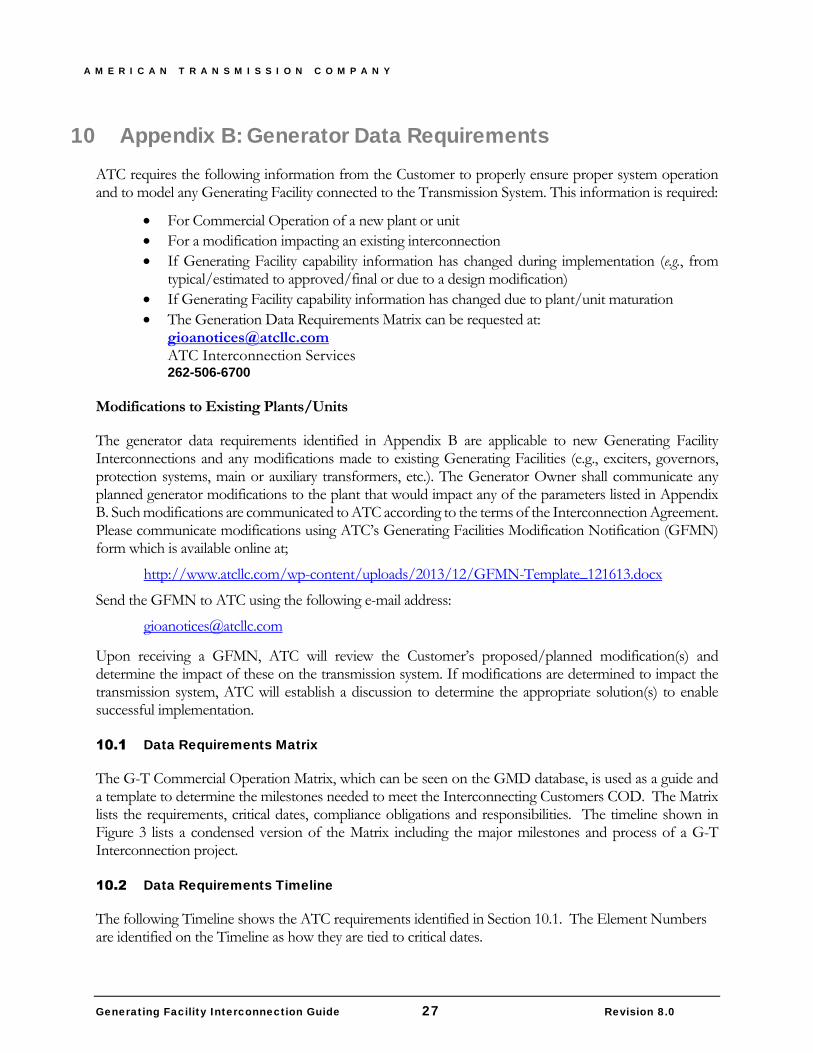
10 Appendix B: Generator Data Requirements 27
Data Requirements Matrix 27
Data Requirements Timeline 27
11 Appendix C: Generating Unit Test Requirements 29
Data Requirements Timeline 29
A M E R I C A N T R A N S M I S S I O N C O M P A N Y
Generating Facility Interconnection Guide 1 Revision 8.0
1 Introduction Purpose
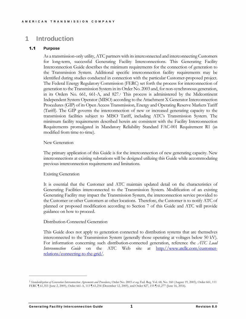
As a transmission-only utility, ATC partners with its interconnected and interconnecting Customers for long-term, successful Generating Facility Interconnections. This Generating Facility Interconnection Guide describes the minimum requirements for the connection of generation to the Transmission System. Additional specific interconnection facility requirements may be identified during studies conducted in connection with the particular Customer-proposed project. The Federal Energy Regulatory Commission (FERC) set forth the process for interconnection of generation to the Transmission System in its Order No. 2003 and, for non-synchronous generation, in its Orders No. 661, 661-A, and 827.3 This process is administered by the Midcontinent Independent System Operator (MISO) according to the Attachment X Generator Interconnection Procedures (GIP) of its Open Access Transmission, Energy and Operating Reserve Markets Tariff (Tariff). The GIP governs the interconnection of new or increased generating capacity to the transmission facilities subject to MISO Tariff, including ATC’s Transmission System. The minimum facility requirements described herein are consistent with the Facility Interconnection Requirements promulgated in Mandatory Reliability Standard FAC-001 Requirement R1 (as modified from time-to-time).
New Generation
The primary application of this Guide is for the interconnection of new generating capacity. New interconnections at existing substations will be designed utilizing this Guide while accommodating previous interconnection requirements and limitations.
Existing Generation
It is essential that the Customer and ATC maintain updated detail on the characteristics of Generating Facilities interconnected to the Transmission System. Modification of an existing Generating Facility may impact the Transmission System, the interconnection service provided to the Customer or other Customers at other locations. Therefore, the Customer is to notify ATC of planned or proposed modification according to Section 7 of this Guide and ATC will provide guidance on how to proceed.
Distribution-Connected Generation
This Guide does not apply to generation connected to distribution systems that are themselves interconnected to the Transmission System (generally those operating at voltages below 50 kV). For information concerning such distribution-connected generation, reference the ATC Load Interconnection Guide on the ATC Web site at http://www.atcllc.com/customer-relations/connecting-to-the-grid/.
3 Standardization of Generation Interconnection Agreements and Procedures, Order No. 2003 et seq, Fed. Reg. Vol. 68, No. 160 (August 19, 2003), Order 661, 111 FERC ¶ 61,353 (June 2, 2005), Order 661-A, 113 ¶ 61,254 (December 12, 2005), and Order 827, 155 ¶ 61,277 (June 16, 2016).
A M E R I C A N T R A N S M I S S I O N C O M P A N Y
Generating Facility Interconnection Guide 2 Revision 8.0
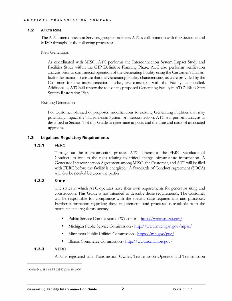
ATC’s Role
The ATC Interconnection Services group coordinates ATC’s collaboration with the Customer and MISO throughout the following processes:
New Generation
As coordinated with MISO, ATC performs the Interconnection System Impact Study and Facilities Study within the GIP Definitive Planning Phase. ATC also performs verification analysis prior to commercial operation of the Generating Facility using the Customer’s final as-built information to ensure that the Generating Facility characteristics, as were provided by the Customer for the interconnection studies, are consistent with the Facility, as installed. Additionally, ATC will review the role of any proposed Generating Facility in ATC’s Black Start System Restoration Plan.
Existing Generation
For Customer planned or proposed modifications to existing Generating Facilities that may potentially impact the Transmission System or interconnection, ATC will perform analysis as described in Section 7 of this Guide to determine impacts and the time and costs of associated upgrades.
Legal and Regulatory Requirements
FERC
Throughout the interconnection process, ATC adheres to the FERC Standards of Conduct4 as well as the rules relating to critical energy infrastructure information. A Generator Interconnection Agreement among MISO, the Customer, and ATC will be filed with FERC before the facility is energized. A Standards of Conduct Agreement (SOCA) will also be needed between the parties.
State
The states in which ATC operates have their own requirements for generator siting and construction. This Guide is not intended to describe those requirements. The Customer will be responsible for compliance with the specific state requirements and processes. Further information regarding these requirements and processes is available from the pertinent state regulatory agency:
Public Service Commission of Wisconsin - http://www.psc.wi.gov/
Michigan Public Service Commission - http://www.michigan.gov/mpsc/
Minnesota Public Utilities Commission - https://mn.gov/puc/
Illinois Commerce Commission - http://www.icc.illinois.gov/
NERC
ATC is registered as a Transmission Owner, Transmission Operator and Transmission
4 Order No. 888, 61 FR 21540 (May 10, 1996)
A M E R I C A N T R A N S M I S S I O N C O M P A N Y
Generating Facility Interconnection Guide 3 Revision 8.0
Planner, with both the Midcontinent Reliability Organization (MRO) and ReliabilityFirst Corporation (RFC) under the requirements of the electric reliability organization, the North American Electric Reliability Corporation (NERC).
ATC and the Customer will plan, design, construct, own, operate, and maintain their respective facilities within the Transmission System, Interconnection Facilities, and Generating Facility consistent with applicable Reliability Standards.
2 New or Modified Generating Facility Interconnection Process
The specific steps and requirements of the process for interconnecting new generating capacity to ATC’s Transmission System are set forth in detail in MISO’s Business Practices Manual (BPM) – Generator Interconnection. This guideline is intended to provide further information concerning how ATC can assist the Customer throughout this process.
Initiation and Development
A Customer request for interconnection to MISO begins the MISO Pre-Queue and Application Review process. The specific requirements of the interconnection request are available on the MISO website Generator Interconnection page at: https://www.misoenergy.org/Planning/GeneratorInterconnection/Pages/GeneratorInterconnection.aspx In addition to the formal mechanisms, ATC encourages communication throughout the process and offers meeting with prospective generator Customers prior to and during the development of the interconnection request.
Interconnection Studies
MISO Related Interconnection Studies
ATC will work with the Customer throughout the study process, including participating in Ad-Hoc meetings the Customer may request beyond the standard queue process discussions. The MISO queue process involves a series of interconnection studies including preliminary system impact, final system impact, interconnection facilities, and network upgrades facilities studies, as shown at https://www.misoenergy.org/Library/Repository/Study/Generator%20Interconnection/GI%20Process%20Flow%20Diagram.pdf and further detailed Attachment X of the MISO Tariff.
The Customer may consult the MISO BPM for Generator Interconnection for further details on milestones and the scope, timeframe and deposits required for each of the Interconnection Studies.
Other ATC Interconnection Studies and Considerations
The power generation and transmission landscape is rapidly evolving due to the growing use of new and emerging technologies. While the use of these technologies provides unique benefits, if not properly applied, their interactions with the system can outage or damage equipment or result in degraded system performance. To ensure that this does not occur, special studies are often required
A M E R I C A N T R A N S M I S S I O N C O M P A N Y
Generating Facility Interconnection Guide 4 Revision 8.0
that have not traditionally been part of the planning process. This section is intended to provide an introduction to these studies, the phenomena they analyze, and when they might be required. It is not meant to be an exhaustive list of all possible new concerns or types of studies but rather a high-level overview to illustrate the possible and probable areas of concern.
The implementation of new generation or transmission devices utilizing power electronic conversion equipment is one example of a situation which may require additional special studies. Alternatively, the siting of new traditional generation or transmission devices near existing devices with power electronic conversion equipment may also require additional studies.
The special studies are typically electro-magnetic transient (EMT) studies which ATC prefers to perform using the PSCAD/EMTDC software. As such, appropriate detailed PSCAD models will be required to be delivered for all projects which utilize power electronic converter based technologies. The use of a generic PSCAD model will typically not produce simulation results of acceptable accuracy. Models using binary/DLLs of the actual control and protection code from the converters and control and protection systems are usually required to accurately model complete device control details. Acceptability of specific models will be determined when they are delivered. ATC can be contacted to provide more detailed information on PSCAD model preferences and supported simulation features.
The specific types of studies of concern may include, but are not limited to, the following:
a. Studies required in “weak grid” conditions Control interactions between multiple nearby power electronic or converter
based devices (type 3 or 4 wind machines, solar PV, HVDC, STATCOM, SVC, etc.)
Sub-synchronous studies (near converter based generation, HVDC, SVCs, STATCOMs, etc.). For example, Sub-Synchronous Torsional Interaction (SSTI), Sub-Synchronous Resonance (SSR), Sub-Synchronous Oscillations (SSO), Sub-Synchronous Control Interaction (SSCI), etc.
Fault ride through performance verification (e.g., to support FERC Order 828, PRC-024-2, etc.). This could be especially applicable to converter based generation which may have unusual responses during and after fault conditions.
Other “weak grid” related studies for devices connecting to an area with low short circuit strength (voltage regulation, other control or protection system tuning, etc.)
b. Control interaction studies required for non-weak grid conditions (e.g., power electronic/converter devices in close proximity to each other, etc.)
c. Power quality around generators or other devices utilizing power electronic converters; especially those with IGBTs. This includes harmonics, interharmonics, and other applicable power quality topics. This may apply to power electronic or converter based devices (type 3 or 4 wind machines, solar PV, HVDC, STATCOM, SVC, etc.)
Screening level studies and engineering judgment will be used, as appropriate, to determine the depth and breadth of detailed analysis required for the concerns and topics outlined above.
A M E R I C A N T R A N S M I S S I O N C O M P A N Y
Generating Facility Interconnection Guide 5 Revision 8.0
Data Requirements
Information is required from the Customer during the interconnection study process under the GIP and throughout the life of the interconnected operation of the Generating Facility. Generally, the information required during the GIP is noted in the MISO BPM. Additional details are included in Appendix B of this Guide. Section 7 of this Guide addresses ATC’s process for working with Customers to manage and maintain accurate data once new generating capacity achieves Commercial Operation.
Interconnection Agreement
After the Interconnection Studies are completed and prior to final design and construction of any required Network Upgrades, the Customer, ATC and MISO will execute a Generator Interconnection Agreement (GIA). The GIA sets forth a schedule of milestones for the construction of the Interconnection Facilities and Network Upgrades necessary to interconnect the proposed new generating capacity, as determined by the Interconnection Studies. The schedule reflects the expected time to obtain all necessary governmental and regulatory approvals and permits required for the construction and operation of the Generating Facility, Interconnection Facilities, and Network Upgrades.
The GIA also establishes the terms and conditions for the interconnected operation of the Generating Facility including, among other things, operational coordination, outage scheduling, coordination of planned and emergent maintenance, future modifications, billings and payments and other communications and coordination procedures. Some additional detail in this regard is provided in Section 7 of this Guide.
Coordination with Local Utilities
Generating Facility interconnection projects require significant coordination with other local utilities. As a transmission-only company, ATC does not provide local distribution utility services, but as a business partner, ATC supports the integration of new generation into its territory. The Customer is responsible for compliance with the requirements of the local distribution utilities and while this Guide is not intended to describe those requirements in detail, there are a number of typical issues that warrant consideration early in the interconnection process.
a. Facilities locations and potential conflicts Overhead distribution facilities Underground distribution facilities Delivery route for large equipment, including “crane-walk” plans for equipment
installation b. Metering Balancing authority metering5 Revenue metering
c. Temporary (construction) and permanent service Auxiliary power
5 Consult ATC’s Coordination of Balancing Authority Business Practice for guidance on the coordination of Balancing Authority Area (BAA) facilities associated with generator interconnections.
A M E R I C A N T R A N S M I S S I O N C O M P A N Y
Generating Facility Interconnection Guide 6 Revision 8.0
3 Design Requirements Interconnection Configuration
Minimum Configuration
The configuration of the interconnection substation will depend on several factors including, but not limited to the number and size of generating units connected, the nominal voltage of the transmission facilities to which the generation is being interconnected, the number of transmission outlets either existing or required and whether or not any of the transmission lines are part of a black start system restoration path. The configuration of the Interconnection Facilities will be determined through the study process. However, the exact transmission line and substation locations may be modified during the detailed design and regulatory process.
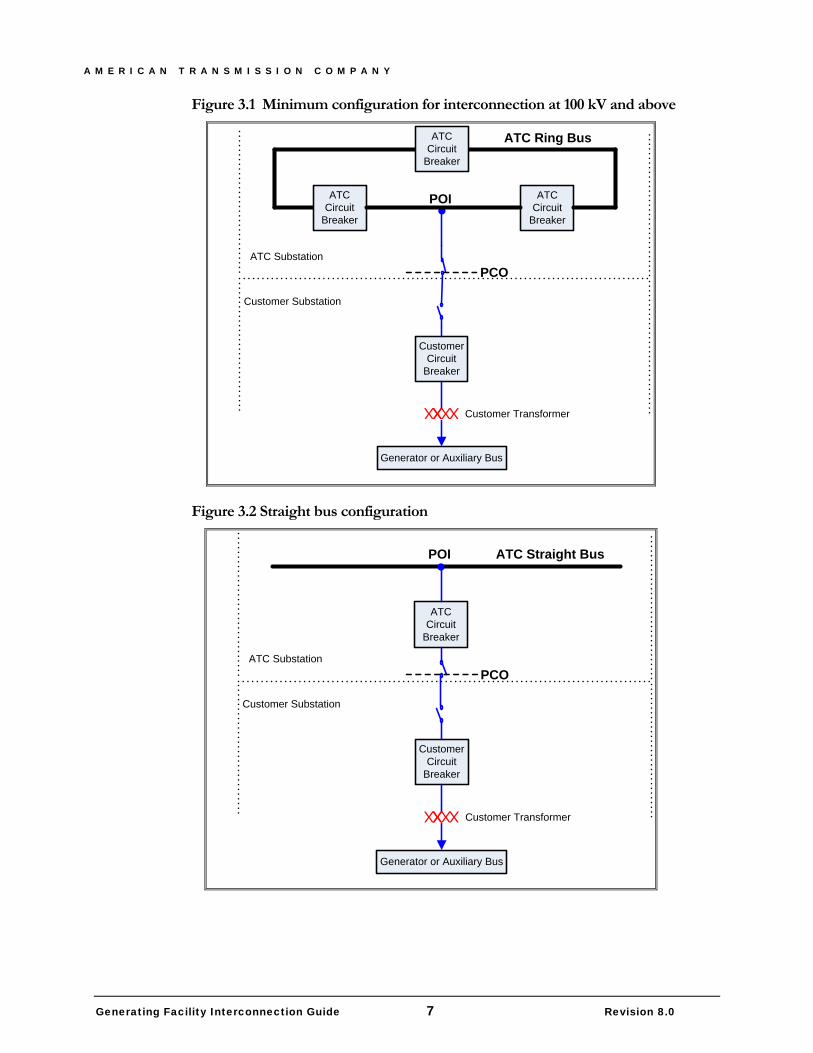
As shown in Figure 1, for interconnection to the Transmission System at voltages of 100 kV and above, the minimum configuration for the ATC interconnection substation will be a three-position ring bus. Straight bus configurations may be considered for interconnection at voltages below 100 kV, subject to the provisions of Section 7.6 of this Guide. As shown in Figure 2, an ATC-owned circuit breaker and disconnect switch in series with the Customer’s transformer circuit breaker as part of the ATC Interconnection Facilities will be required for any straight bus configuration. As shown in both Figure 3.1 and Figure 3.2, for all interconnections, the Customer will, at minimum, procure, install, own and maintain a circuit breaker and disconnect switch between the Point of Change of Ownership (PCO) and the Customer’s transformer (step-up or auxiliary) to transmission voltage to be located in the Customer’s substation.
A M E R I C A N T R A N S M I S S I O N C O M P A N Y
Generating Facility Interconnection Guide 7 Revision 8.0
Figure 3.1 Minimum configuration for interconnection at 100 kV and above
Customer Circuit
Breaker
POI
PCO
XXXX X
Customer Transformer
ATC Ring Bus
ATC Substation
Customer Substation
ATC Circuit
Breaker
ATC Circuit
Breaker
ATC Circuit
Breaker
Generator or Auxiliary Bus
Figure 3.2 Straight bus configuration
Customer Circuit
Breaker
POI
PCO
XXXX X
Customer Transformer
ATC Straight Bus
ATC Substation
Customer Substation
ATC Circuit
Breaker
Generator or Auxiliary Bus
A M E R I C A N T R A N S M I S S I O N C O M P A N Y
Generating Facility Interconnection Guide 8 Revision 8.0
Proximity of ATC and Customer Substations
For an ATC interconnection substation built adjacent to the Customer’s substation, the connection between the ATC network bus and the Customer’s substation will be considered by ATC as a bus extension and a bus protection scheme will be required. However, if the substations are not adjacent, the connection will be considered a line, not a bus extension and a line protection scheme will be employed by ATC.
Demarcation and Ownership
The Point of Interconnection (POI) will be the point at which the ATC Interconnection Facilities connect to the ATC interconnection substation bus. The PCO will be at the point at which the strain bus from the Customer’s substation connects to the dead-end structure of the ATC Interconnection Facilities located in the ATC interconnection substation. In the event that the interconnection is via rigid bus conductor, the PCO will be the terminal connection of ATC’s switch in the ATC interconnection substation.
Substation Site
ATC’s interconnection substation will be designed as an entirely separate substation from the Customer’s substation. It is recommended that the Customer provide a suitable site for the ATC interconnection substation. The Customer will be required to convey to ATC all necessary easements, in a form acceptable to ATC, over all property owned, leased or otherwise controlled by the Customer, including easements for ingress and egress to permit ATC access to all of the ATC Interconnection Facilities and Network Upgrades, which are on the property of the Customer. Additionally, the site that the Customer provides to ATC must be sufficiently large enough to accommodate the present and future uses of ATC and meet the rough grading requirements of ATC. ATC design expectations and review of rough grading will be detailed in the GIA Milestone tables in Exhibit B. The Customer will be responsible for obtaining all necessary zoning, building, environmental, storm water retention or detention and other permits or approvals. The specific real estate requirements will be determined during the detailed design. If the Customer’s substation is adjacent to the ATC interconnection substation, a fence separating them will be required. ATC will design, own and maintain this common fence according to its standards.
Power Factor
Power Factor Requirements for Interconnection Generating Units are as follows. ATC’s standard power factor range for synchronous and non-synchronous (e.g., wind turbines, solar) generation is 0.95 leading (when a Generating Facility is consuming reactive power from the Transmission System) to 0.90 lagging (when a Generating Facility is supplying reactive power to the Transmission System)6.
Static reactive power sources can only be used to make up for losses between the machine terminal and the POI for synchronous machines and losses between the terminal of the machines and the high side of the GSU for non-synchronous machines. All other reactive power to meet the power factor requirement must be provided by continuous and sustainable dynamic sources. Operation across the entire power factor range must be fully dynamic, variable, and capable of sustained
6 These values have been approved by the FERC for use by ATC. (cf. FERC Orders ER05-1475 and ER06-866)
A M E R I C A N T R A N S M I S S I O N C O M P A N Y
Generating Facility Interconnection Guide 9 Revision 8.0
indefinite operation.
Static sources can be switched on or off in the range of seconds and provide reactive power in large discrete blocks. Cap Banks are considered static sources of reactive power.
Dynamic sources can provide variable amounts of reactive power in a few milliseconds. Static Var Compensators (SVCs), Static Synchronous Compensators (STATCOMs), Flexible AC Transmission Systems (FACTS), inverters, and synchronous condensers are all considered dynamic sources of reactive power.
The Generating Facility must be capable of maintaining ATC’s standard power factor range at all power output levels by providing continuous dynamic reactive power at the following locations:
a. The Point for Interconnection for all synchronous generator. For synchronous machines, the interconnection studies will account for the net effect of all energy production devices and losses on the Customer’s side of the POI.
b. The high-side of the generator step-up transformer (GSU) for all non-synchronous generators. For non-synchronous machines, the interconnection studies will account for the net effect of all energy production devices and losses on the Customer’s side of the GSU. Dynamic reactive power provided by non-synchronous generators must meet the following requirement from FERC order 827 Item 35:
“Non-synchronous generators may meet the dynamic reactive power requirement by utilizing a combination of the inherent dynamic reactive power capability of the inverter, dynamic reactive power devices (e.g., Static VAR Compensators), and static reactive power devices (e.g., capacitors) to make up for losses.”
POI Voltage
The interconnecting generator must be capable of automatically and dynamically maintaining a POI voltage schedule that is specified by the Transmission Operator. Any generator interconnected within the ATC system is expected to maintain a voltage of 1.02 p.u. at its POI to facilitate transmission operations reliability under normal system conditions (system intact) and P1 and P2 Contingencies, unless another voltage level is communicated to the generator by the ATC Transmission Operator (cf. NERC Reliability Standard VAR-001).
Low Voltage Ride-Through Capability
All generators connected to the Transmission System must be capable of “riding through” disturbances that depress system voltages, as required by FERC Orders 661-A and 693. All generators must communicate the low voltage as-built ride-through capability of the Generating Facility following the Commercial Operation Date (COD).
Generation Voltage, Reactive Power and/or Power Factor Control
The Customer must design the Generating Facility such that controls are included on each generating unit to be interconnected to control voltage, reactive power, and/or power factor consistent with the requirements of the GIA and Section 7.2 of this Guide. Additionally, the Customer must design the Generating Facility to include provisions for power system stabilizers,
A M E R I C A N T R A N S M I S S I O N C O M P A N Y
Generating Facility Interconnection Guide 10 Revision 8.0
except where exempted by the FERC. Depending on the size and location of the generator, a power system stabilizer may be required for interconnection.
Power Quality, Voltage Flicker and Harmonics
The design, energization and operation of any Generating Facilities must be consistent with ATC’s Tariff-required Planning Criteria and Planning Guidelines PLG-CR-0004 and 0005 regarding power quality including harmonics; permissible voltage deviations, flicker and distortion; and distortion of current waveforms as measured at the POI. ATC’s Planning Criteria and Operating Instructions are available upon request.
Frequency
The interconnected Transmission System has a nominal operating frequency of 60 Hz. The Customer will install both generation controls and protective relaying equipment necessary to maintain proper Transmission System frequency (cf. Section 0).
Fault Current
Customer facilities connected to ATC’s Transmission System can be subjected to fault levels that are largely the product of system characteristics and interconnection impedance. The Customer’s facilities must possess sufficient fault interrupting and momentary withstand ratings to meet the maximum expected fault current, with appropriate margin for future system growth. ATC will provide the transmission contribution to the fault current levels at the Point of Interconnection in the System Impact Study report and otherwise at the request of the Customer.
Auxiliary Power
The Customer shall procure its own primary and secondary sources of auxiliary power for its substation. ATC shall procure its own primary source of auxiliary power for the ATC interconnection substation. ATC may require the Customer to provide, at Customer’s expense, a secondary source of auxiliary power to the ATC interconnection substation off of the Customer’s substation equipment.
Voltage Level
New interconnections must effectively address the voltage requirements of both this section and Section 7.2. ATC operates transmission facilities predominantly at nominal system voltages of 69, 138, 345 kV. For the purposes of this guide, any reference to 138 kV voltage levels shall also encompass interconnections to ATC’s 115 kV system as well. ATC will discuss with the Customer, on a case-by-case basis, requirements associated with interconnections to the relatively small amount of 161 and 230 kV facilities owned and operated by ATC.
Basic Impulse Insulation Level
ATC and the Customer must ensure that all equipment is adequately protected from excessive system over-voltages. This includes selection of equipment Basic Impulse Insulation Level (BIL) and protective devices (e.g. surge arresters) to achieve proper insulation coordination across the interconnection.
ATC designs its transmission facilities for the BILs shown in Table 3.1 below. Interconnections at 230kV or 161kV will be reviewed on an exception basis. New substations energized at 115 kV will
A M E R I C A N T R A N S M I S S I O N C O M P A N Y
Generating Facility Interconnection Guide 11 Revision 8.0
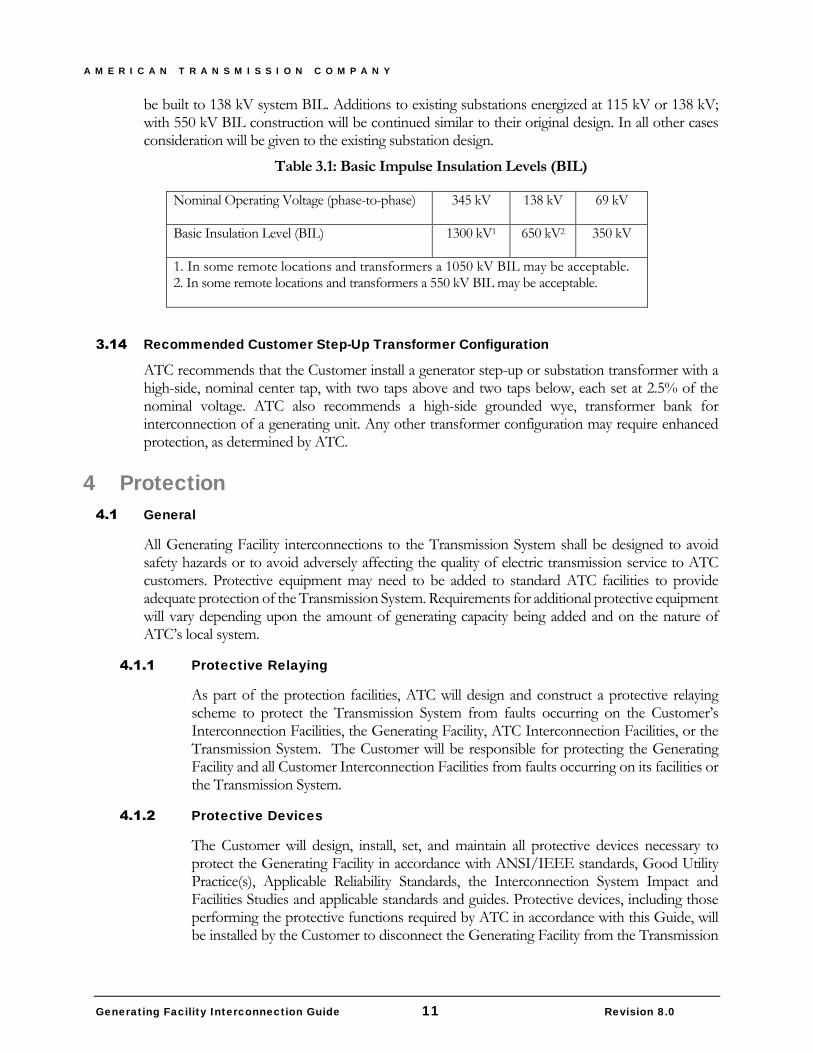
be built to 138 kV system BIL. Additions to existing substations energized at 115 kV or 138 kV; with 550 kV BIL construction will be continued similar to their original design. In all other cases consideration will be given to the existing substation design.
Table 3.1: Basic Impulse Insulation Levels (BIL)
Nominal Operating Voltage (phase-to-phase) 345 kV 138 kV 69 kV
Basic Insulation Level (BIL) 1300 kV1 650 kV2 350 kV
1. In some remote locations and transformers a 1050 kV BIL may be acceptable. 2. In some remote locations and transformers a 550 kV BIL may be acceptable.
Recommended Customer Step-Up Transformer Configuration
ATC recommends that the Customer install a generator step-up or substation transformer with a high-side, nominal center tap, with two taps above and two taps below, each set at 2.5% of the nominal voltage. ATC also recommends a high-side grounded wye, transformer bank for interconnection of a generating unit. Any other transformer configuration may require enhanced protection, as determined by ATC.
4 Protection General
All Generating Facility interconnections to the Transmission System shall be designed to avoid safety hazards or to avoid adversely affecting the quality of electric transmission service to ATC customers. Protective equipment may need to be added to standard ATC facilities to provide adequate protection of the Transmission System. Requirements for additional protective equipment will vary depending upon the amount of generating capacity being added and on the nature of ATC’s local system.
Protective Relaying
As part of the protection facilities, ATC will design and construct a protective relaying scheme to protect the Transmission System from faults occurring on the Customer’s Interconnection Facilities, the Generating Facility, ATC Interconnection Facilities, or the Transmission System. The Customer will be responsible for protecting the Generating Facility and all Customer Interconnection Facilities from faults occurring on its facilities or the Transmission System.
Protective Devices
The Customer will design, install, set, and maintain all protective devices necessary to protect the Generating Facility in accordance with ANSI/IEEE standards, Good Utility Practice(s), Applicable Reliability Standards, the Interconnection System Impact and Facilities Studies and applicable standards and guides. Protective devices, including those performing the protective functions required by ATC in accordance with this Guide, will be installed by the Customer to disconnect the Generating Facility from the Transmission
A M E R I C A N T R A N S M I S S I O N C O M P A N Y
Generating Facility Interconnection Guide 12 Revision 8.0
System whenever a fault, abnormal operating condition or equipment failure occurs on or within the Generating Facility. The Customer will ensure that such protective devices and related equipment properly coordinate with ATC protective equipment, both locally and remotely and provide a comparable level of protection to the Generating Facility and the Customer Interconnection Facilities as is provided by ATC for the ATC Interconnection Facilities and Transmission System. The specific requirements and specific protective devices to be installed will be determined in the Interconnection Studies. Customer owned 345 kV and above breakers should be rated for the application; including generator synchronization.
ATC Protection Relay
The Customer will allow ATC to review the Generating Facility protection, control design and settings and their coordination, where applicable, with the ATC protective devices prior to and after the COD. ATC reserves the right to refuse to allow the Customer to initiate the tender of energy to the Transmission System if, in the judgment of ATC, the Generating Facility protection devices, controls or overall protection methods do not adequately prevent the Generating Facility from introducing or causing an adverse impact on the Transmission System.
Protective Relay Requirements
Protective relays utilized by the Customer shall:
a. Meet or exceed ANSI/IEEE standards for protective relays (i.e., C37.90-1989, C37.90.1, C37.90.2, and C37.90.3).
b. Have the appropriate documentation covering application, testing, maintenance, and service.
c. Give positive indication of what has caused a trip (targets).
d. Have a means of testing that does not require disturbance to wiring (e.g. a draw-out case, test-blocks, test switches, etc.).
The Customer shall use microprocessor-based protective relays that include self-diagnostic abilities, sequence of events, event-recording capabilities, and operating flexibility.
Frequency Protection (IEEE 81)
The design of the Generating Facility relating to over-frequency protection of the Generating Facility is discretionary with the Customer. However, the over-frequency protection used by the Customer will be provided to ATC. Under-frequency protection will be in accordance with the Applicable Reliability Standards.
Customer Breaker Failure Protection (IEEE 50BF)
The Customer shall install a local dedicated 50BF breaker failure protective relay on its breaker on the high-side of the generator step-up transformer. The 50BF relay will be coordinated with ATC in order to trip adjacent substation breakers, in the event the generator breaker fails to successfully open for any reason.
A M E R I C A N T R A N S M I S S I O N C O M P A N Y
Generating Facility Interconnection Guide 13 Revision 8.0
Synchronism Check Relay (IEEE 25)
The Customer will synchronize the Generating Facility to the Transmission System across the Customer-owned breaker installed on the high-side of the generator step-up transformer. The Customer shall provide a synchronism-check relay to supervise the automatic or manual synchronization of the Generating Facility to the Transmission System. Automatic synchronism-check relays will contain the manufacturer’s optional voltage monitoring functions and supervise the closing of the circuit breaker. ATC will be entitled to review the settings and operation of the Generating Facility’s synchronism check relay.
Bus Differential Protection (IEEE 87)
The Customer shall provide a dedicated current transformer input to the ATC bus differential protection scheme to provide coordinated bus differential protection of ATC’s bus. This current transformer shall be placed in a manner to ensure that the bus differential protection overlaps the generator bus or step-up transformer protection.
Reverse Power (IEEE 32)
The protection system for all combustion turbine generators connected to the Transmission System and the reverse power relay pickup shall be set no more than -7% of the machine rated MVA to protect the Transmission System from a possible voltage collapse due to the gas turbine high power consumption during motoring.
Power Transformer Ground Time Overcurrent Protection (IEEE 51N)
The Customer shall install ground time overcurrent protection for all generator step-up and auxiliary power transformers to protect them from internal ground faults. Such protection will be coordinated with the backup ground time overcurrent protection.
Protection Redundancy
In accordance with Good Utility Practice, the Customer shall design protection schemes such that no single component failure will prevent the isolation of faults and/or failed equipment. This may require providing redundant or backup protective schemes with separate sensing sources, separate trip paths, dual trip coils on breakers, separate control power supplies, etc.
Generator Tripping
Each generating unit of the Generating Facility must be capable of disconnecting itself from ATC’s Transmission System in the event of a system fault, abnormal operating condition or equipment or system failure. If the Generating Facility is a wind farm, it must be disconnected at the collector bus to remove the ground source of the collector to eliminate its contribution to a system fault, abnormal operating condition or equipment or system failure.
Recommended Generator Protection Functions
ATC recommends the following protective functions, which may provide the Generating Facility with additional backup protection from transmission relaying malfunctions, misoperations, equipment or system failure.
Phase Distance (Impedance) Protection (IEEE 21)
A M E R I C A N T R A N S M I S S I O N C O M P A N Y
Generating Facility Interconnection Guide 14 Revision 8.0
The Customer’s distance relay zone that extends into the Transmission System should be time-coordinated with line protective relays to assure transmission protection operates first. The time delay will be set higher than a second zone clearing time for a line fault (typically 20 cycles). Impedance protection is provided for a generating unit when transmission line(s) that connect it to the Transmission System are protected with phase distance relays.
Time Overcurrent with Voltage Control/Restraint (IEEE 51V)
The Customer’s overcurrent relays that are voltage-controlled or voltage-restrained should be set below load current for adequate sensitivity to Transmission System faults while restraining operation under emergency overload conditions. To prevent miscoordination with transmission relaying, overcurrent relays should be sufficiently time-delayed. The time-delay setting should be based on the worst-case coordination with ATC protective relays, which is usually a delayed trip with breaker failure clearing times. Backup time overcurrent protection is provided for a Generating Facility when transmission line(s) that connect it to the transmission grid are protected by overcurrent relays.
Backup Ground Time Overcurrent Protection (IEEE 51N)
It is recommended that any backup ground time overcurrent protection operate for ground faults at the end of all transmission lines coming out of the Generating Facility and be set to coordinate with the slowest ground fault protection on the Transmission System. This relay is typically installed in the high-side neutral of the generator step-up transformer.
Negative Sequence Current (Unbalanced Load) Protection (IEEE 46)
The Customer should apply a negative sequence time overcurrent relay to protect the Generating Facility from external unbalanced conditions such as system phase-to-phase faults and open conductors that can damage a generating unit(s).
Out-of-Step (Loss of Synchronism) Protection (IEEE 78)
The Customer shall ensure that each generating unit is capable of separating from the Transmission System before an “out-of-step condition” or loss of synchronism can occur.
Voltage Balance (IEEE 60)
The Customer should ensure the following voltage-dependent protective functions are blocked when a loss of fuse is detected to prevent relaying misoperation:
a. Phase distance (impedance) protection (IEEE 21);
b. Under-voltage protection (IEEE 27);
c. Loss of field (under-excitation) protection (IEEE 40);
d. Time overcurrent with voltage control/restraint (IEEE 51V);
e. Under-frequency protection (IEEE 81).
Transmission Line Automatic Reclosing Near Generating Facility
The automatic re-closing of breakers on ATC transmission lines can be potentially damaging to Customer equipment that is in close electrical proximity to the lines. As a general policy, ATC will
A M E R I C A N T R A N S M I S S I O N C O M P A N Y
Generating Facility Interconnection Guide 15 Revision 8.0
not eliminate automatic reclosing of overhead transmission lines near a Generating Facility because that could significantly affect the reliability of service to transmission customers. In order to mitigate possible negative effects of line automatic reclosing on generating facilities, ATC typically will not reclose lines for the most severe three-phase faults on the Transmission System and will reclose a line first at a terminal remote from the Generating Facility bus, followed by synchronism check reclosing of the breaker at the Generating Facility bus. Automatic reclosing is single-shot and is blocked should a fault be of a permanent nature. ATC may install additional equipment to minimize the potentially adverse effects of automatic reclosing. This usually consists of communication and/or control equipment to disconnect the Generating Facility (or to confirm that it is disconnected) before an ATC line is reclosed.
In cases where the ATC interconnection substation has two transmission outlets, a line side single-phase voltage-sensing potential device will be installed at the remote terminal of each line. Additionally, the automatic reclosing scheme at the remote terminal of each line will support disabling automatic reclosing via supervisory control.
Grounding
The Customer must design, install, and maintain grounding facilities to ground the Customer’s Interconnection Facilities. ATC reserves the right to approve the grounding system design to ensure that the grounding system properly protects ATC’s Interconnection Facilities. Additionally, ATC will determine the required short circuit ratings for all of the ATC Interconnection Facilities and Network Upgrades during the detailed design of such facilities. The Customer shall provide appropriately sized or short circuit-rated Interconnection Facilities comparable to those required by ATC.
The Customer and ATC will design their respective substations’ ground grids separately for the maximum available fault current as specified by ATC. The ground grids of both substations will then be connected together at several locations along the common fence (if applicable) before the substations are placed in-service. The Customer and ATC’s designs shall address safe touch and step potential not only for their respective ground grids, but also for along the fence line with the connection of the ground grids.
Equipment Ratings
ATC shall determine the individual equipment ratings for the ATC Interconnection Facilities and Network Upgrades during the detailed design of the facilities in accordance with its design standards and the Interconnection Studies. The Customer shall size its Interconnection Facilities to appropriately coordinate with the ATC Interconnection Facilities. ATC and the Customer shall exchange information before the COD or implementation of any future modifications, including identification of the most limiting piece of equipment, to achieve common understanding of each party’s respective Interconnection Facilities’ normal and emergency ratings.
5 Telemetry and Metering Requirements Telemetry
The Customer shall provide ATC with real-time analog and digital Generating Facility data. The method in which the signals shall be transmitted to the ATC location will be specified during the detail design of the Interconnection Facilities and Network Upgrades. The Customer shall provide
A M E R I C A N T R A N S M I S S I O N C O M P A N Y
Generating Facility Interconnection Guide 16 Revision 8.0
the data in a format acceptable to ATC. If the Customer cannot supply the data in an acceptable format like ICCP, then ATC will install an RTU at the Generating Facility to collect this information. Additionally, the Customer will install and maintain interconnection metering and status data for the connection of each generating unit, except as noted below.
In general, ATC requires continuous telemetry of the items listed in Sections 5.1.1. through 5.1.3.
Status of Circuit Breakers
The status of circuit breakers owned by the Customer with the following functions will be communicated to ATC continuously:
• Breakers capable of disconnecting the Generating Facility from the Transmission System
• Breakers capable of disconnecting any auxiliary load from the Transmission System • Breakers capable of disconnecting any device that is required to be in-service to meet
the unit(s) requirements for reactive power compensation as part of the Interconnection Agreement
Status of Relay Equipment
Status of relay equipment is required when the Customer’s relay equipment is protecting, as primary or backup, any of ATC’s Transmission System equipment.
Instantaneous Real and Reactive Power Data
Instantaneous real and reactive power data are required for each generating unit at the generator terminal or compensated to the generator terminal. For wind farms, aggregated real and reactive power data at the collection substation are required. Load values, MW and MVAR, for the following locations will need to be continuously communicated to ATC:
• All Generating Facility auxiliary loads connected between the generator terminal and the POI with the Transmission System
• All Generating Facility auxiliary loads connected directly to the Transmission System
• All third-party loads supplied from the Generating Facility of Customer Interconnection Facilities
Instantaneous Voltage Data
Instantaneous voltage data needs to be continuously communicated at the terminal of each generator for all generator types with the exception of wind farms. For wind farms, instantaneous voltage data will be collected at the substation bus. Instantaneous voltage data will also be collected and communicated at the terminal of any device installed to provide static or dynamic reactive power compensation within the Customer’s substation.
Status and Readiness
Continuous communication is required as to the status of whether the following is in-service and “ready”:
A M E R I C A N T R A N S M I S S I O N C O M P A N Y
Generating Facility Interconnection Guide 17 Revision 8.0
• Any power system stabilizer installed • Automatic voltage regulator (AVR) • Any special protection system (SPS) • Any reactive power compensation, whether static or dynamic
Local Balancing Authority Metering
The Customer is responsible for working with an appropriate Local Balancing Authority to install necessary metering facilities, including instrument transformers within the Customer’s interconnection substation. Prior to energizing the interconnection via the Transmission System, the Customer must provide evidence of a Balancing Authority Agreement to ATC. See ATC’s Coordination of Local Balancing Authority Metering Boundary Modifications Business Practice for additional information:
http://www.atcllc.com/customer-relations/business-practices/
6 Testing, Inspection and Commissioning Testing and Inspection
Before ATC provides final approval for energization of the interconnection, the Customer must demonstrate to ATC, through witnessed tests and/or certified test documentation, that the Generating Facility and each generating unit will not have adverse impact on the operation of the Transmission System. Such tests and inspections will include pre-energization testing of equipment connected to the transmission bus, protection and control systems and pre-commercial testing of the governor, excitation and/or power system stabilizer controls. Protection and control systems include, but are not limited to, AC auxiliary, DC systems, relaying systems, potential and current circuits, and communication systems.
Initial Transformer Energization
Installation and commissioning of a new Customer transformer will require the initial energization to occur from the Transmission System. Prior to initial energization of a new Customer transformer at a new or existing Generating Facility and if determined necessary by ATC, the Customer must permanently install mitigation equipment (e.g., pre-insertion resistors on the high-side transformer circuit breaker) or commission a technical study of the initial energization event to ensure that the initial energization of the transformer will not result in any unacceptable impact to the Transmission System or any other interconnected customers. If the Customer commissions a technical study for this purpose, a final report must be submitted to ATC for review no less than ten (10) business days prior to the Customer’s planned date for initial energization.
Reduction of DC Residual Flux
The Customer will perform an excitation current test to determine if the core of any new Customer transformer is magnetized. If the test establishes that the core is magnetized, the Customer will perform the transformer manufacturer’s recommended procedures to reduce the residual DC flux on the core. The Customer will then re-perform the excitation current test to verify that the core has been de-magnetized. The Customer will provide documented results of these procedures to ATC prior to energization of the Customer transformer.
Generating Facility Synchronization
A M E R I C A N T R A N S M I S S I O N C O M P A N Y
Generating Facility Interconnection Guide 18 Revision 8.0
Unless otherwise permitted by ATC, the Generating Facility shall be synchronized to the Transmission System at the Customer’s step-up transformer’s high-side circuit breaker installed at the POI. ATC shall furnish Transmission System bus potentials that may be used by the Customer for synchronizing the Generating Facility to the Transmission System.
7 Requirements after Commercial Operation The GIA (per Section 2.4) establishes the terms and conditions for the interconnected operation of the Generating Facility after achieving Commercial Operation, especially procedures for communication and coordination among the Customer, ATC, and MISO. ATC sees such effective communication and coordination as essential to planning, operating, and maintaining a safe and reliable Transmission System and Generating Facility Interconnection. This section provides summary guidance on certain Interconnection Agreement provisions that may impact the Customer’s decision-making in the design of new or modified Generating Facilities for interconnection to the Transmission System. The Customer should consult the Interconnection Agreement for additional detail on requirements pertinent to ongoing interconnected operations.
Operating Guidelines
The specific requirements of each interconnection will dictate the establishment of mutually agreeable interconnection and/or operating guidelines applicable to each Generating Facility, if necessary.
Generating Facility Voltage Schedule
NERC Mandatory Reliability Standards VAR-001 and VAR-002 set forth the requirements Transmission Operators and Generator Operators/Owners must follow to maintain network voltage schedules. VAR-001 requires that the Transmission Operator specify a voltage schedule at the POI “and direct the Generator Operator to comply with the schedule in automatic voltage control mode (AVR in-service and controlling voltage).” VAR-002 requires that the Generator Operator maintain the voltage schedule set by ATC and operate each generator in automatic voltage control mode, among other requirements.
VAR-001 provides that “[t]he voltage schedule is a voltage target that must be maintained within a tolerance band during a specified period.” ATC’s standard voltage schedule is a target voltage of 102% of the nominal voltage at the Point of Interconnection within a maximum permissible range of 95% to 105% until ATC specifies a new voltage schedule. The Generating Facility must be designed and operated for this voltage schedule unless directed otherwise. In addition, operation within a desired tolerance band of 100% to 105% is recommended to ensure efficient and reliable operation of the bulk electric system due to real time system conditions that may not have been specifically modeled in the planning horizon.
Unit Stability
The Customer shall operate the Generating Facility in accordance with the operating requirements of ATC, MISO, NERC, and any applicable regional entity in addition to the stability requirements identified in the Interconnection System Impact Study report, or its equivalent, prepared for the interconnection and which have been posted on the Transmission Provider’s OASIS at:
http://www.oatioasis.com/MISO/index.html
A M E R I C A N T R A N S M I S S I O N C O M P A N Y
Generating Facility Interconnection Guide 19 Revision 8.0
System Restoration (Black Start)
The Customer is not required to operate as a Black Start Resource unless designated by a separate Black Start Service agreement. However, in accordance with Good Utility Practice, Customer will participate, when called upon by MISO or ATC, in ATC’s Black Start System Restoration Plan for the Generating Facility and ATC’s Transmission System, as well as any verification testing. The Customer is required to supply to ATC its facility black out plans. These plans shall include the equivalized impedance of the systems within the Generating Facility auxiliary system to large motors expected to be started during emergency conditions along with the appropriate time-domain modeling assumptions for each large motor to be used by ATC to confirm ATC’s Black Start Plan. ATC will use this information to study the ability of a degraded system to start large motors, such as fans, pumps, and other equipment during system black outs and restoration. The Customer will also be expected to participate in any Black Start System Restoration Plan verification testing.
Maintenance Testing
After commissioning of the Generating Facility, periodic maintenance, testing, modification or troubleshooting of Customer equipment shall be done with consideration of the impact to the Transmission System. Protective relay testing that can trip any element of the Transmission System shall be discussed and approved by the ATC system operator 10 business days prior to testing of equipment.
Detection of and Tripping for an Electrical Island Condition
In circumstances where the Generating Facility has no governor controls and the transmission system design could result in an islanding condition for the outage of two transmission elements, ATC requires the Customer to implement additional protection systems as mutually agreed by the Customer and ATC to prevent generation from being isolated or islanded with interconnected load. Alternatively, ATC will require the Customer to curtail their generation for circumstances that could result in an island condition with the next contingency.
Generating Facility Modifications
It is of critical importance for reliable interconnection service and operation of the Transmission System that the Generator Owner communicate to ATC proposed and planned changes to the Generating Facility, Interconnection Facilities and related equipment. Communication of changes should occur as early as possible using the ATC Generating Facilities Modification Notification (GFMN) form found at:
http://www.atcllc.com/wp-content/uploads/2013/12/GFMN-Template_121613.docx
The GFMN form may be sent to ATC via email at:
The GFMN is to be used to communicate events including, but not limited to, the following:
• Plant/Unit modifications due to emergency changes
• Planned/Proposed plant/unit modifications
• Plant/unit retirements – note that the GFMN does not replace other notification requirements; it is in addition to those requirements
• Plant/unit development • The submittal of unit verification data created as a result of periodic testing
A M E R I C A N T R A N S M I S S I O N C O M P A N Y
Generating Facility Interconnection Guide 20 Revision 8.0
For the submittal of generator data/information, as required for reporting data related to NERC and/or Regional Entity Standards and/or as required reporting due to MISO transmission needs, please submit this data to [email protected]. An example of this type of information includes:
• The submittal of generator data/information, as required, for reporting data related to NERC and/or Regional Entity standards
• The submittal of generator data/information as required reporting due to MISO transmission and/or energy market needs
If proposed modifications are determined to have an impact on the Transmission System, ATC and the Customer will collaborate on the appropriate solution(s) to enable successful implementation of the proposed unit modification.
The Annual Review
ATC performs an Annual Generator Review to ensure the accuracy of its information for Generating Facilities connected to the Transmission System. Information obtained via the Annual Review also contributes to ATC filings made to RFC, MRO and NERC. The primary ATC functions using the Annual Review results are Planning, System Protection and Real Time Operations.
ATC will send an email communication to Generator Owners requesting the following information to initiate the Annual Review process:
• Any planned retirements of plants/units
• Any planned development of new plants/units
• Any modifications made in the prior year for which ATC is unaware
• Any modifications planned or proposed for the future
• Special data reviews such as capability curve confirmations
Generating Unit Testing
ATC desires to support and take part in the Generator Owner’s generator reactive power capability verification testing. Coordination between the Generator Owner and ATC will provide a better test environment. ATC encourages the Generator Owner to use the NERC MOD 25 format to report the results, the same format Generator Owners use to report this data to NERC. Appendix C, Generating Unit Test Requirements, contains detailed information for coordinating testing.
8 Requirements Assuring Reliable Operation at the Interconnection Point
ATC desires to ensure the operational reliability of interconnections to the ATC Transmission System. The Interconnection Customer will meet the following needs in order to receive approval to commence operation of a new plant or move to operation any modifications impacting an interconnection point.
The following dates are used as end dates for receiving all required documentation and test results: • 60 Calendar days prior to the first synchronization date for fossil or nuclear plants • 60 Calendar days prior to the COD for all other plant types
A M E R I C A N T R A N S M I S S I O N C O M P A N Y
Generating Facility Interconnection Guide 21 Revision 8.0
For new plants, ATC approval will provide the Interconnection Customer with the ability to submit the COD letter identified in Appendix E of the GIA. For modifications to existing facilities impacting a generation to transmission interconnection point that do not require MISO intervention, ATC approval will allow the interconnection customer to move forward with operation.
Appendix B of this Guide identifies potential reporting requirements including:
• Description of the Generator Requirements Matrix which identifies the timing, rationale and uses of the data.
• Generator Requirements Milestone and Process Timeline which provides a picture of the milestones, showing where the milestones fall.
Effective Date: 12/13/17 Revision: 8.0 TITLE: Generating Facility Interconnection Guide Page 21 of 32
Randy Karls, Director, Customer Relations and Interconnection Services
Approved by:
A M E R I C A N T R A N S M I S S I O N C O M P A N Y
Generating Facility Interconnection Guide 22 Revision 8.0
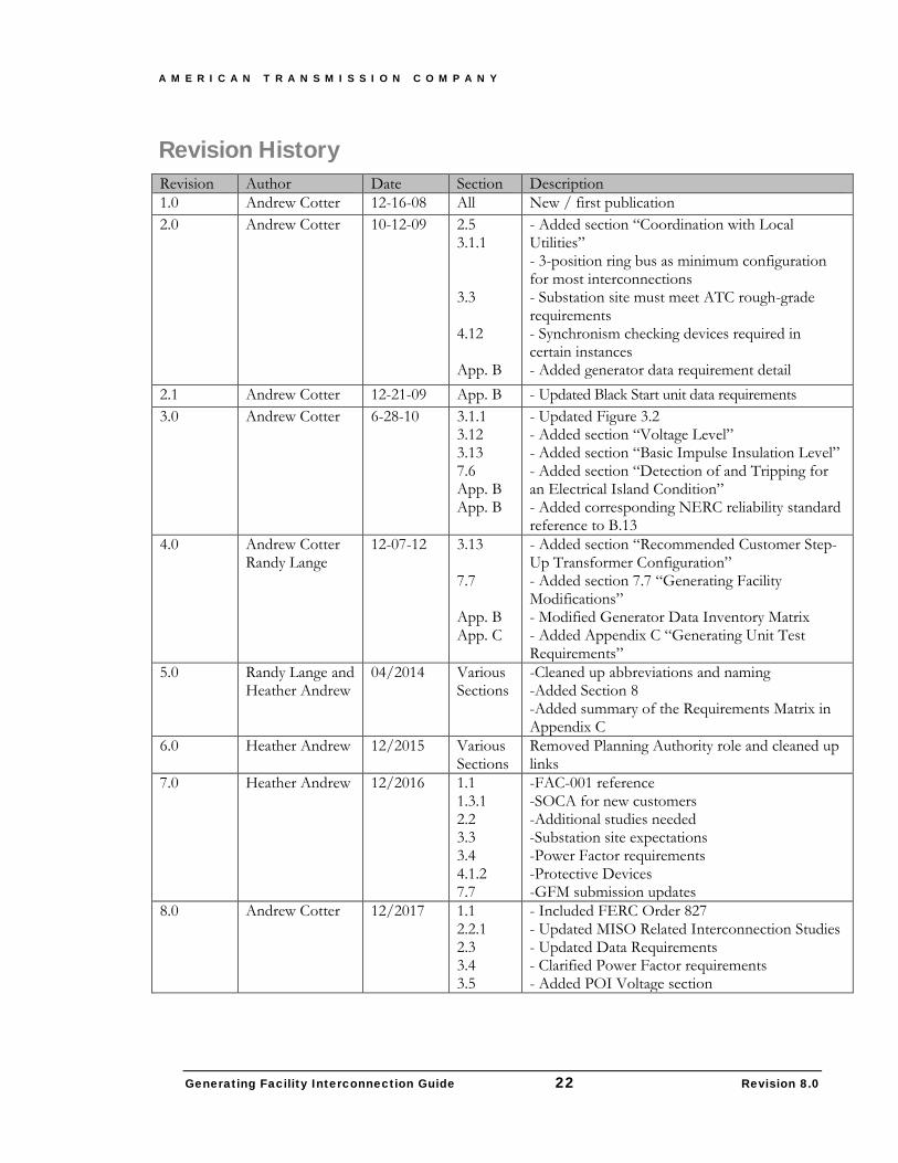
Revision History Revision Author Date Section Description 1.0 Andrew Cotter 12-16-08 All New / first publication 2.0 Andrew Cotter 10-12-09 2.5
3.1.1 3.3 4.12 App. B
- Added section “Coordination with Local Utilities” - 3-position ring bus as minimum configuration for most interconnections - Substation site must meet ATC rough-grade requirements - Synchronism checking devices required in certain instances - Added generator data requirement detail
2.1 Andrew Cotter 12-21-09 App. B - Updated Black Start unit data requirements 3.0 Andrew Cotter 6-28-10 3.1.1
3.12 3.13 7.6 App. B App. B
- Updated Figure 3.2 - Added section “Voltage Level” - Added section “Basic Impulse Insulation Level” - Added section “Detection of and Tripping for an Electrical Island Condition” - Added corresponding NERC reliability standard reference to B.13
4.0 Andrew Cotter Randy Lange
12-07-12 3.13 7.7 App. B App. C
- Added section “Recommended Customer Step-Up Transformer Configuration” - Added section 7.7 “Generating Facility Modifications” - Modified Generator Data Inventory Matrix - Added Appendix C “Generating Unit Test Requirements”
5.0 Randy Lange and Heather Andrew
04/2014 Various Sections
-Cleaned up abbreviations and naming -Added Section 8 -Added summary of the Requirements Matrix in Appendix C
6.0 Heather Andrew 12/2015 Various Sections
Removed Planning Authority role and cleaned up links
7.0 Heather Andrew 12/2016 1.1 1.3.1 2.2 3.3 3.4 4.1.2 7.7
-FAC-001 reference -SOCA for new customers -Additional studies needed -Substation site expectations -Power Factor requirements -Protective Devices -GFM submission updates
8.0 Andrew Cotter 12/2017 1.1 2.2.1 2.3 3.4 3.5
- Included FERC Order 827 - Updated MISO Related Interconnection Studies - Updated Data Requirements - Clarified Power Factor requirements - Added POI Voltage section
A M E R I C A N T R A N S M I S S I O N C O M P A N Y
Generating Facility Interconnection Guide 23 Revision 8.0
9 Appendix A: Glossary of Terms Any capitalized terms not defined herein will have the meanings set forth in the MISO Tariff.
Applicable Regional Reliability Organization: the reliability organization of NERC applicable to the Balancing Authority of the Transmission System to which the Generating Facility is directly interconnected. ATC is a registered member of both the Midwest Reliability Organization (MRO) and ReliabilityFirst Corporation (RFC).
Applicable Reliability Standards: the requirements and guidelines of NERC, the Applicable Regional Reliability Organization, and the Balancing Authority of the Transmission System to which the Generating Facility is directly interconnected.
ATC Interconnection Facilities: all facilities and equipment owned by ATC from the Point of Change of Ownership to the Point of Interconnection as identified in the GIA. The ATC Interconnection Facilities are sole-use facilities and do not include Network Upgrades or the Customer’s Interconnection Facilities.
Balancing Authority: an entity responsible for managing an electric system area (a Balancing Authority Area) bounded by interconnection metering and telemetry; and capable of controlling generation to maintain its interchange schedule with other Balancing Authority Areas and contributing to frequency regulation and which has received certification by NERC or a Regional Reliability Council of NERC.
Commercial Operation: the status of a Generating Facility that has commenced generating electricity for sale, excluding electricity generated during Trial Operation.
Customer: any entity that already has interconnected or proposes to interconnect a Generating Facility with the Transmission System.
Customer’s Interconnection Facilities: all facilities and equipment, as identified in the GIA, that are located between the Generating Facility and the Point of Change of Ownership, including any equipment necessary to physically and electrically interconnect the Generating Facility to the Transmission System.
Electric Reliability Organization: the North American Electric Reliability Corporation authorized by the FERC to promulgate, seek approval for, and enforce Mandatory Reliability Standards.
Electrical Island: An isolated operating condition which couples a generator(s) to local load with no external connection to the Transmission System.
Emergency Condition: a condition or situation: (1) that in the reasonable judgment of the Party making the claim is imminently likely to endanger, or is contributing to the endangerment of, life, property, or public health and safety; or (2) that, in the case of either MISO or ATC, is imminently likely (as determined in a non-discriminatory manner) to cause a material adverse effect on the security of, or damage to the Transmission System, the ATC Interconnection Facilities or the electric systems of others to which the Transmission System is directly connected; or (3) that, in the case of the Customer, is imminently likely (as determined in a non-discriminatory manner) to cause a material adverse effect on the security of, or damage to, the Generating Facility or the Customer’s Interconnection Facilities. System restoration and black-start will be considered Emergency Conditions; provided that the Customer is not obligated by this LGIA to
A M E R I C A N T R A N S M I S S I O N C O M P A N Y
Generating Facility Interconnection Guide 24 Revision 8.0
possess black-start capability. Any condition or situation that results from lack of sufficient generating capacity to meet load requirements or that results solely from economic conditions will not constitute an Emergency Condition, unless one of the enumerated conditions or situations identified in this definition also exists.
Federal Power Act: the Federal Power Act, as amended, 16 U.S.C. §§ 791a et seq.
FERC: the Federal Energy Regulatory Commission or its successor.
Generating Facility: the Customer’s device(s) for the production of electricity consisting of one or more generating units identified in the Interconnection Request, but not including the Customer’s Interconnection Facilities.
Generating Facility Capacity: the aggregate net capacity of the Generating Facility where it includes multiple generating units at the Point of Interconnection.
Generator Interconnection Agreement (GIA): the interconnection agreement in the form of Appendix 6 of MISO’s Generator Interconnection Procedures.
Generator Interconnection Procedures (GIP): the interconnection procedures that are included in the MISO Tariff and applicable to an Interconnection Request pertaining to a Generating Facility.
Generator Upgrades: the additions, modifications, and upgrades to the electric system of an existing generating facility or of a higher queued Generating Facility at or beyond the Point of Interconnection to facilitate interconnection of the Generating Facility and render the transmission service necessary to affect the Customer’s wholesale sale of electricity in interstate commerce.
Good Utility Practice: any of the practices, methods and acts engaged in or approved by a significant portion of the electric industry during the relevant time period, or any of the practices, methods and acts which, in the exercise of reasonable judgment in light of the facts known at the time the decision was made, could have been expected to accomplish the desired result at a reasonable cost consistent with good business practices, reliability, safety and expedition. Good Utility Practice is not intended to be limited to the optimum practice, method, or act to the exclusion of all others, but rather to be acceptable practices, methods, or acts generally accepted in the region.
Governmental Authority: any federal, state, local or other governmental regulatory or administrative agency, court, commission, department, board, or other governmental subdivision, legislature, rulemaking board, tribunal, or other governmental authority having jurisdiction over the Parties, their respective facilities, or the respective services they provide, and exercising or entitled to exercise any administrative, executive, police, or taxing authority or power; provided, however, that such term does not include the Customer, MISO, ATC, or any Affiliate thereof.
Initial Synchronization Date: the date upon which the Generating Facility is initially synchronized and upon which Trial Operation may begin.
In-Service Date: the date upon which the Customer reasonably expects it will be ready to begin use of the ATC Interconnection Facilities to obtain backfeed power.
A M E R I C A N T R A N S M I S S I O N C O M P A N Y
Generating Facility Interconnection Guide 25 Revision 8.0
Interconnection Agreement: the agreement executed or to be executed by ATC, the Customer, and MISO and filed at the FERC; representing mutually agreeable terms and conditions pertinent to the interconnection of the Generating Facility to the Transmission System. The form of this agreement not only acceptably includes MISO’s pro forma Generator Interconnection Agreement (GIA), but also agreements executed and filed for Generating Facilities whose interconnection preceded the existence of the GIA.
Interconnection Facilities: all facilities and equipment between the Generating Facility and the Point of Interconnection, including any modification, additions or upgrades that are necessary to physically and electrically interconnect the Generating Facility to the Transmission System. Interconnection Facilities do not include Generator Upgrades or Network Upgrades.
Interconnection Facilities Study: a study conducted by MISO, or its agent, for the Customer to determine a list of facilities (including the ATC Interconnection Facilities, System Protection Facilities, and if such upgrades have been determined, Network Upgrades, Distribution Upgrades, Generator Upgrades, and upgrades on Affected Systems, as identified in the Interconnection System Impact Study), the cost of those facilities, and the time required to interconnect the Generating Facility with the Transmission System. The scope of the study is defined in Section 8 of MISO Generator Interconnection Procedures.
Interconnection Feasibility Study: a preliminary evaluation of the system impact of interconnecting the Generating Facility to the Transmission System, the scope of which is described in Section 6 of MISO Generator Interconnection Procedures.
Interconnection Request: a Customer’s request, in the form of Appendix 1 to the Generator Interconnection Procedures, to interconnect a new Generating Facility, or to increase the capacity of, or make a Material Modification to the operating characteristics of, an existing Generating Facility that is interconnected with the Transmission System.
Interconnection Study: any of the following studies: the Interconnection Feasibility Study, the Interconnection System Impact Study, and the Interconnection Facilities Study, or the Restudy of any of the above, described in the Generator Interconnection Procedures.
Interconnection System Impact Study: an engineering study that evaluates the impact of the proposed interconnection on the safety and reliability of Transmission System and, if applicable, an Affected System. The study will identify and detail the system impacts that would result if the Generating Facility were interconnected without project modifications or system modifications, focusing on the Adverse System Impacts identified in the Interconnection Feasibility Study, or to study potential impacts, including but not limited to those identified in the Scoping Meeting as described in the Generator Interconnection Procedures.
Mandatory Reliability Standards: those standards promulgated and approved by NERC as the ERO, or any Regional Entity authorized to do so, as ratified and approved by the FERC that are applicable to ATC and the Customer.
MISO: the Midcontinent Independent System Operator, Inc., the Regional Transmission Organization that administers the tariff and provides transmission and energy market services over the transmission facilities of its transmission-owning members in interstate commerce.
A M E R I C A N T R A N S M I S S I O N C O M P A N Y
Generating Facility Interconnection Guide 26 Revision 8.0
NERC: the North American Electric Reliability Corporation or its successor organization.
Network Upgrades: the additions, modifications, and upgrades to the Transmission System required at or beyond the point at which the Interconnection Facilities connect to the Transmission System to accommodate the interconnection of the Generating Facility to the Transmission System.
Point of Change of Ownership (PCO): the point, as set forth in Appendix A to the GIA or Exhibit 1 of an Interconnection Agreement, where the Customer’s Interconnection Facilities connect to the ATC Interconnection Facilities.
Point of Interconnection (POI): the point at which the ATC Interconnection Facilities connect to the ATC interconnection substation bus.
Regional Entity: the entity or entities that have entered into a delegation agreement with NERC and that have responsibility for the audit and investigation of the compliance with Mandatory Reliability Standards.
Tariff: MISO Tariff through which open access transmission service and Interconnection Service are offered, as filed with the FERC, and as amended or supplemented from time to time, or any successor tariff.
Transmission Operator: any entity responsible for the reliability of its “local” transmission system, and that operates or directs the operations of the transmission facilities.
Transmission System: the facilities owned by ATC and controlled or operated by MISO and ATC at voltages ≥69 kV and are used to provide transmission service or Wholesale Distribution Service under the Tariff.
Trial Operation: the period during which the Customer is engaged in on-site test operations and commissioning of the Generating Facility prior to Commercial Operation.
A M E R I C A N T R A N S M I S S I O N C O M P A N Y
Generating Facility Interconnection Guide 27 Revision 8.0
10 Appendix B: Generator Data Requirements ATC requires the following information from the Customer to properly ensure proper system operation and to model any Generating Facility connected to the Transmission System. This information is required:
• For Commercial Operation of a new plant or unit • For a modification impacting an existing interconnection • If Generating Facility capability information has changed during implementation (e.g., from
typical/estimated to approved/final or due to a design modification) • If Generating Facility capability information has changed due to plant/unit maturation • The Generation Data Requirements Matrix can be requested at:
[email protected] ATC Interconnection Services 262-506-6700
Modifications to Existing Plants/Units
The generator data requirements identified in Appendix B are applicable to new Generating Facility Interconnections and any modifications made to existing Generating Facilities (e.g., exciters, governors, protection systems, main or auxiliary transformers, etc.). The Generator Owner shall communicate any planned generator modifications to the plant that would impact any of the parameters listed in Appendix B. Such modifications are communicated to ATC according to the terms of the Interconnection Agreement. Please communicate modifications using ATC’s Generating Facilities Modification Notification (GFMN) form which is available online at;
http://www.atcllc.com/wp-content/uploads/2013/12/GFMN-Template_121613.docx
Send the GFMN to ATC using the following e-mail address:
Upon receiving a GFMN, ATC will review the Customer’s proposed/planned modification(s) and determine the impact of these on the transmission system. If modifications are determined to impact the transmission system, ATC will establish a discussion to determine the appropriate solution(s) to enable successful implementation.
Data Requirements Matrix
The G-T Commercial Operation Matrix, which can be seen on the GMD database, is used as a guide and a template to determine the milestones needed to meet the Interconnecting Customers COD. The Matrix lists the requirements, critical dates, compliance obligations and responsibilities. The timeline shown in Figure 3 lists a condensed version of the Matrix including the major milestones and process of a G-T Interconnection project.
Data Requirements Timeline
The following Timeline shows the ATC requirements identified in Section 10.1. The Element Numbers are identified on the Timeline as how they are tied to critical dates.
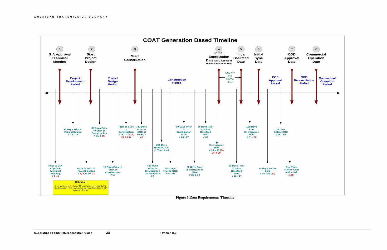
A M E R I C A N T R A N S M I S S I O N C O M P A N Y
Generating Facility Interconnection Guide 28 Revision 8.0
COAT Generation Based Timeline
StartProjectDesign
StartConstruction
Initial Energization
Date (ATC Assets in Place and Functional)
CODApproval
Date
CommercialOperation
Date
ConstructionPeriod
CODApproval
Period
COD Reconciliation
Period
ProjectDesignPeriod
CommercialOperation
Period
ProjectDevelopment
Period
14 Days Before COD
# 96 – 98
30 Days Before COD
# 44 – 63 (63)
At Energization
Date# 33 – 38 (34,
36 & 38)
30 Days Prior to Energization
Date# 29 & 30
90 Days Prior to
Energization Date
# 24 - 27
180 Days Prior to COD
# 64 - 95
30 Days Prior to Project Design
# 12 - 14
Prior to Start of Project Design# 7, 8, 9, 10, 11
Any Time Prior to COD
# 99 – 102 (100)
GIA Approval Technical Meeting
InitialSyncDate
InitialBackfeed
Date
Prior to GIA Approval Technical Meeting# 1 - 6
Usuallythe
SameDate
30 Days Prior to Initial
Backfeed Date
# 40 - 41
DefinitionItem numbers in Red are ATC internal or occur prior to the
GIA Execution. Therefore, these are not reflected in the GIA Appendix B or C.
Prior to Start of
Construction# 18 – 23 (18,
21 & 23)
1 2 3 4 5 6 7 8
90 Days Prior to Start of
Construction# 15 & 16
14 Days Prior to Start of
Construction# 17
420 Days Prior to
Energization (14 Months) #
28
60 Days Prior to Initial
Backfeed Date# 39
120 Days After
Energization Date
# 31 - 32
720 Days Prior to COD (2 Years) #
42
360 Days Prior to COD (1 Year) # 43
Figure 3 Data Requirements Timeline
A M E R I C A N T R A N S M I S S I O N C O M P A N Y
Generating Facility Interconnection Guide 29 Revision 8.0
11 Appendix C: Generating Unit Test Requirements This Appendix summarizes the detailed guide Generator Owners use in scheduling generating unit testing with ATC as well as sets forth the communication requirements for the data derived from such testing. A sample of a generator capability curve can be seen in Figure 4. A flowchart documenting the process is included in Figure 5. The entire guide can be seen through the Generator Modeling Database extranet site. For further details on the extranet site contact ATC-Interconnection Services.
Data Requirements Timeline
Following are the ATC requirements of a Generator Owner when the Generator Owner is planning to perform a test of a generating unit. The requirement and benefits fall into two categories:
1. Test Plan and Execution a. ATC real time Operations are aware of tests, are then aware of real time system
anomalies and can react accordingly b. ATC Operations can support the Generator Owner test with adjustments to the
transmission system c. ATC System Protection is aware of special conditions that may exist during the test
and can react prior to the test d. ATC Operations EMS function has awareness and can then record specific
reactions during the test for the use in real time operations 2. ATC Receipt of Resulting Test Results
a. Provides/confirms the most current generator capabilities allowing ATC Planning, System Protection and real time Operations to adjust data and system expectations
b. Results can directly impact the outcome of ATC 10-Year Plan c. Satisfies the following Regulatory Requirements:
i. FAC-008 – Facilities Rating Methodology ii. MOD-024 – Identifies the Test Data Required iii. VAR-002 – Identifies the Requirement for the Communication iv. TOP-003– Defines Test Requirements
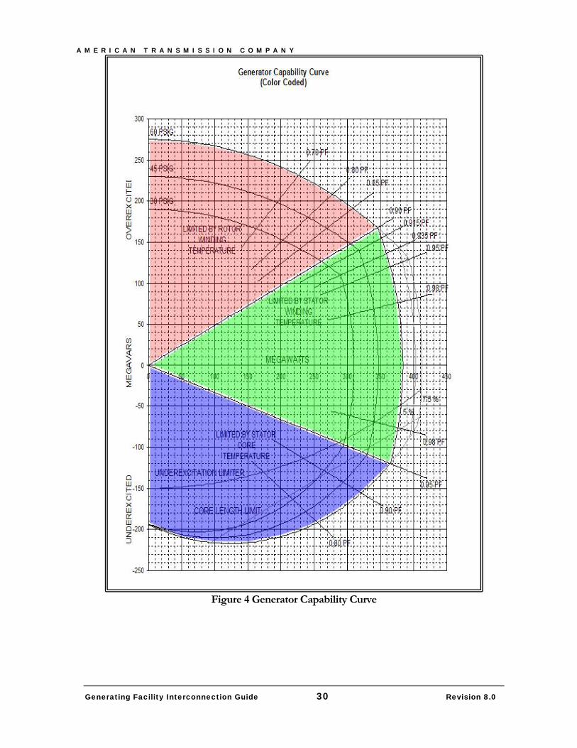
A M E R I C A N T R A N S M I S S I O N C O M P A N Y
Generating Facility Interconnection Guide 30 Revision 8.0
Figure 4 Generator Capability Curve
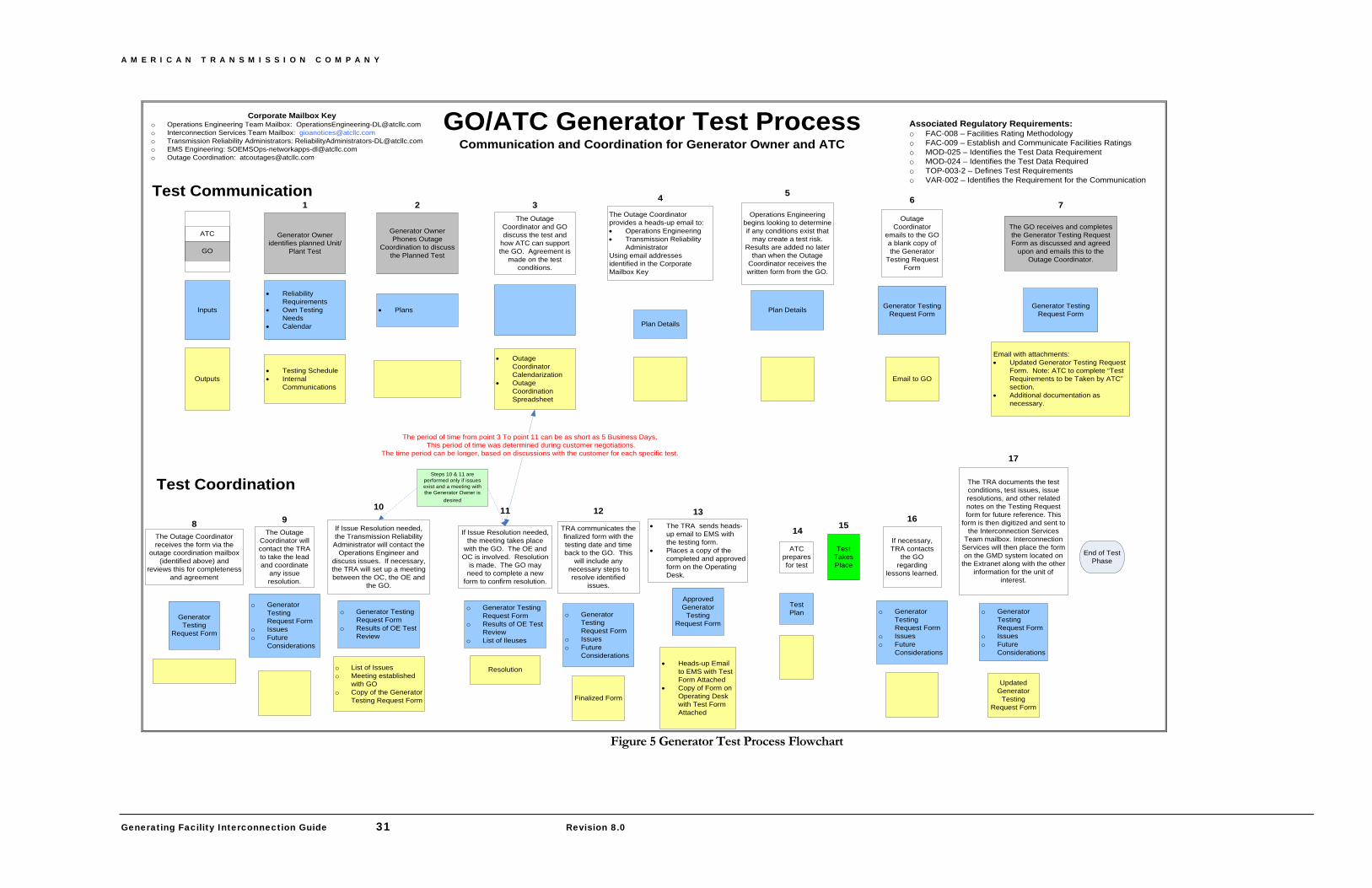
A M E R I C A N T R A N S M I S S I O N C O M P A N Y
Generating Facility Interconnection Guide 31 Revision 8.0
GO/ATC Generator Test ProcessCommunication and Coordination for Generator Owner and ATC
Generator Owner identifies planned Unit/
Plant Test
• Reliability Requirements
• Own Testing Needs
• Calendar
• Testing Schedule• Internal
Communications
Inputs
Outputs
ATC
GO
Generator Owner Phones Outage
Coordination to discuss the Planned Test
• Plans
The Outage Coordinator and GO discuss the test and
how ATC can support the GO. Agreement is
made on the test conditions.
• Outage Coordinator Calendarization
• Outage Coordination Spreadsheet
Outage Coordinator
emails to the GO a blank copy of the Generator
Testing Request Form
Generator Testing Request Form
Email to GO
• The TRA sends heads-up email to EMS with the testing form.
• Places a copy of the completed and approved form on the Operating Desk.
Approved Generator
Testing Request Form
• Heads-up Email to EMS with Test Form Attached
• Copy of Form on Operating Desk with Test Form Attached
Test Takes Place
ATC prepares for test
Test Plan
End of Test Phase
Associated Regulatory Requirements:o FAC-008 – Facilities Rating Methodologyo FAC-009 – Establish and Communicate Facilities Ratingso MOD-025 – Identifies the Test Data Requiremento MOD-024 – Identifies the Test Data Requiredo TOP-003-2 – Defines Test Requirementso VAR-002 – Identifies the Requirement for the Communication
The GO receives and completes the Generator Testing Request Form as discussed and agreed
upon and emails this to the Outage Coordinator.
Generator Testing Request Form
Email with attachments:• Updated Generator Testing Request
Form. Note: ATC to complete “Test Requirements to be Taken by ATC” section.
• Additional documentation as necessary.
If Issue Resolution needed, the meeting takes place
with the GO. The OE and OC is involved. Resolution
is made. The GO may need to complete a new
form to confirm resolution.
Resolution
The Outage Coordinator receives the form via the
outage coordination mailbox (identified above) and
reviews this for completeness and agreement
Generator Testing
Request Form
Test Communication
Test Coordination
If Issue Resolution needed, the Transmission Reliability
Administrator will contact the Operations Engineer and
discuss issues. If necessary, the TRA will set up a meeting between the OC, the OE and
the GO.
o List of Issueso Meeting established
with GOo Copy of the Generator
Testing Request Form
o Generator Testing Request Form
o Results of OE Test Review
o Generator Testing Request Form
o Results of OE Test Review
o List of Ileuses
If necessary, TRA contacts
the GO regarding
lessons learned.
o Generator Testing Request Form
o Issueso Future
Considerations
The period of time from point 3 To point 11 can be as short as 5 Business Days. This period of time was determined during customer negotiations.
The time period can be longer, based on discussions with the customer for each specific test.
The Outage Coordinator provides a heads-up email to:• Operations Engineering• Transmission Reliability
AdministratorUsing email addresses identified in the Corporate Mailbox Key
Plan Details
Operations Engineering begins looking to determine if any conditions exist that
may create a test risk. Results are added no later
than when the Outage Coordinator receives the written form from the GO.
Plan Details
1
Corporate Mailbox Keyo Operations Engineering Team Mailbox: [email protected] Interconnection Services Team Mailbox: [email protected] Transmission Reliability Administrators: [email protected] EMS Engineering: [email protected] Outage Coordination: [email protected]
4 532 6 7
814
131110
1516
17
The TRA documents the test conditions, test issues, issue resolutions, and other related notes on the Testing Request form for future reference. This
form is then digitized and sent to the Interconnection Services
Team mailbox. Interconnection Services will then place the form on the GMD system located on
the Extranet along with the other information for the unit of
interest.
o Generator Testing Request Form
o Issueso Future
Considerations
Updated Generator
Testing Request Form
Steps 10 & 11 are performed only if issues exist and a meeting with the Generator Owner is
desired
The Outage Coordinator will contact the TRA to take the lead and coordinate
any issue resolution.
o Generator Testing Request Form
o Issueso Future
Considerations
9TRA communicates the finalized form with the testing date and time back to the GO. This
will include any necessary steps to resolve identified
issues.
o Generator Testing Request Form
o Issueso Future
Considerations
Finalized Form
12
Figure 5 Generator Test Process Flowchart
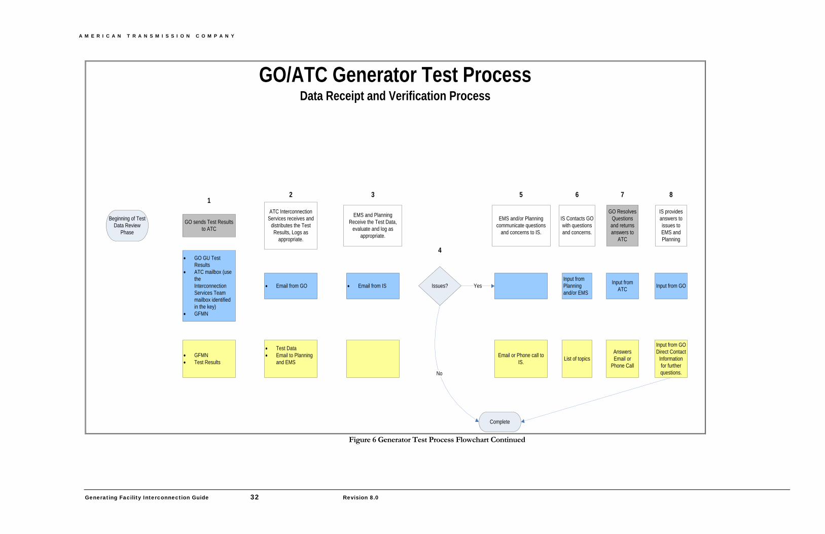
A M E R I C A N T R A N S M I S S I O N C O M P A N Y
Generating Facility Interconnection Guide 32 Revision 8.0
GO/ATC Generator Test ProcessData Receipt and Verification Process
GO sends Test Results to ATC
• GO GU Test Results
• ATC mailbox (use the Interconnection Services Team mailbox identified in the key)
• GFMN
• GFMN• Test Results
ATC Interconnection Services receives and
distributes the Test Results, Logs as
appropriate.
• Email from GO
• Test Data• Email to Planning
and EMS
EMS and Planning Receive the Test Data,
evaluate and log as appropriate.
• Email from IS
Complete
EMS and/or Planning communicate questions
and concerns to IS.
Email or Phone call to IS.
Beginning of Test Data Review
Phase
Issues? Yes
No
IS Contacts GO with questions and concerns.
Input from Planning and/or EMS
List of topics
GO Resolves Questions
and returns answers to
ATC
Input from ATC
AnswersEmail or
Phone Call
IS provides answers to issues to EMS and Planning
Input from GO
Input from GODirect Contact
Information for further questions.
1
4
3 5 6 7 82
Figure 6 Generator Test Process Flowchart Continued