generating set - europa plant op manual.pdf13 32 a 1 pole circuit breaker ... 4. wiring diagram...
TRANSCRIPT
MI455-02-00-00March 2008
GENERATING SET
MG 20 SS-D
OWNERS MANUAL
Generating Set MG 20 SS-D
2 MI455-02-00-00March 2008
1. TECHNICAL SPECIFICATIONS
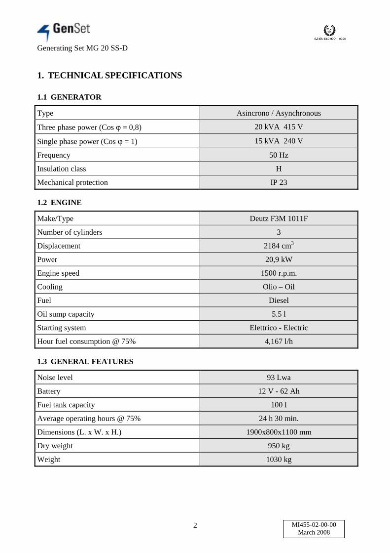
1.1 GENERATOR
Type Asincrono / Asynchronous
Three phase power (Cos = 0,8) 20 kVA 415 V
Single phase power (Cos = 1) 15 kVA 240 V
Frequency 50 Hz
Insulation class H
Mechanical protection IP 23
1.2 ENGINE
Make/Type Deutz F3M 1011F
Number of cylinders 3
Displacement 2184 cm3
Power 20,9 kW
Engine speed 1500 r.p.m.
Cooling Olio – Oil
Fuel Diesel
Oil sump capacity 5.5 l
Starting system Elettrico - Electric
Hour fuel consumption @ 75% 4,167 l/h
1.3 GENERAL FEATURES
Noise level 93 Lwa
Battery 12 V - 62 Ah
Fuel tank capacity 100 l
Average operating hours @ 75% 24 h 30 min.
Dimensions (L. x W. x H.) 1900x800x1100 mm
Dry weight 950 kg
Weight 1030 kg
Generating Set MG 20 SS-D
3 MI455-02-00-00March 2008
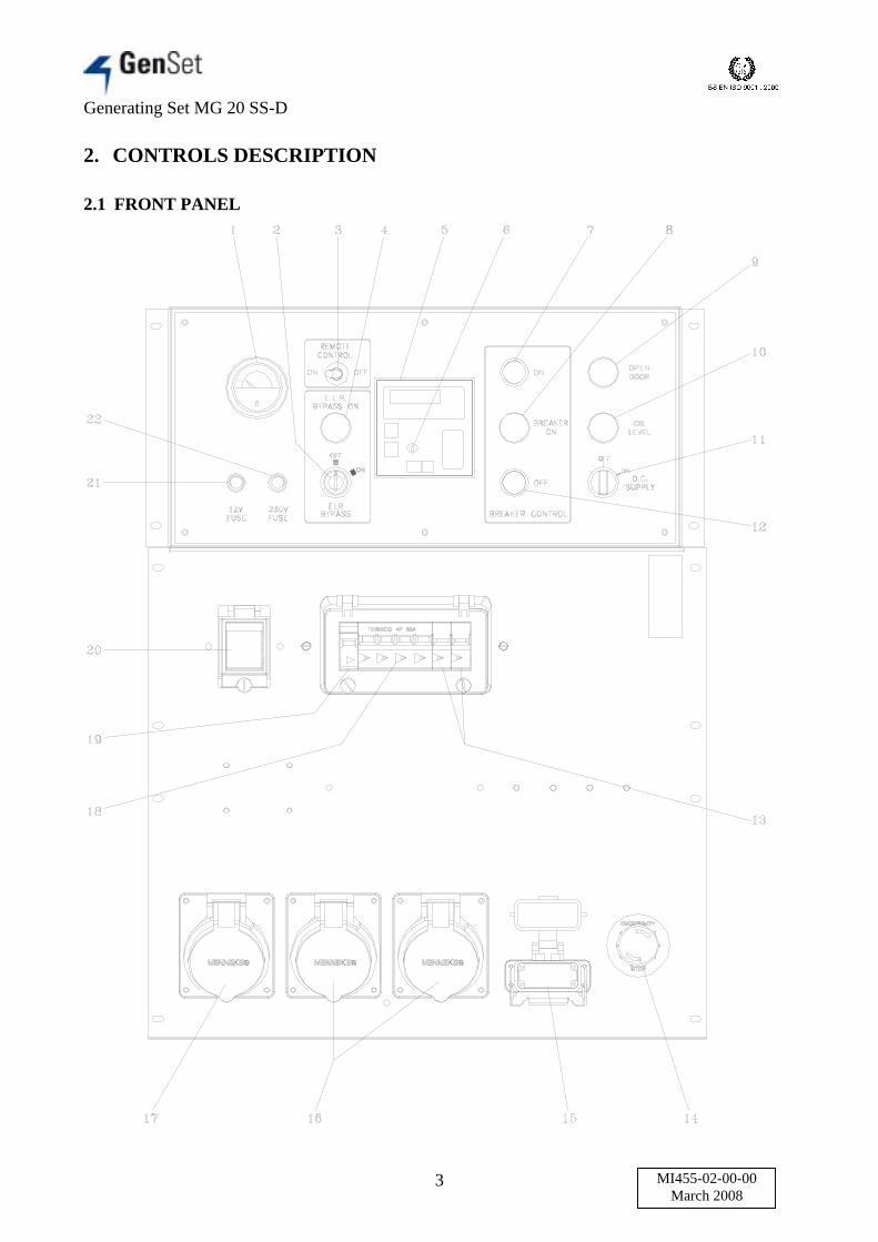
2. CONTROLS DESCRIPTION
2.1 FRONT PANEL

Generating Set MG 20 SS-D
4 MI455-02-00-00March 2008
1 Fuel level gauge
2 Earth leakage relay bypass
3 Remote control switch
4 Earth leakage relay bypass alarm lamp
5 MP24 control unit
6 Starting key
7 “Breaker on” push button
8 “Breaker on” alarm lamp
9 Open door alarm lamp
10 Low oil level alarm lamp
11 DC 24 V supply selector
12 “Breaker off” push button
13 32 A 1 pole circuit breaker
14 Emergency stop button
15 Remote control connector
16 240 V 32 A single phase socket
17 415 V 32 A three phase socket
18 63 A 4 poles circuit breaker
19 240 V tripping coil
20 RD2 earth leakage relay
21 12 V fuse
22 240 V fuse

Generating Set MG 20 SS-D
5 MI455-02-00-00March 2008
2.2 REMOTE CONTROL PANEL
1 Timer / Manual switch
2 Manual mode Stop / Start selector
3 Timer
4 “Breaker on” alarm lamp
5 Emergency stop button
6 12 V fuse
7 Fuel level gauge

Generating Set MG 20 SS-D
6 MI455-02-00-00March 2008
2.3 PANNELLO LATERALE / SIDE PANEL
1 Earth clamp connection
2 R,S,T,N output
3 Safety switch
4 R,S,T,N output cables

Generating Set MG 20 SS-D
7 MI455-02-00-00March 2008
3. RICAMBI / PARTS LIST

Generating Set MG 20 SS-D
8 MI455-02-00-00March 2008
N° Ordering N° Denomination1 6033 Fan2 6032 Fan pin3 4235 Seeger ring4 4026 Bearing5 115743/DX Alternator right support6 114221 Alternator traverse7 115743/SX Alternator left support8 133757 Lower alternator protection9 114366 Rotor
10 119849 Right engine holder spacer11 6036 Blade for inox plate12 105303 Inox plate13 116222 Battery switch cap14 140224 Battery switch support15 139177 Battery switch aluminium plate16 138686 Battery switch17 119850 Left engine holder spacer18 6048/A T3 shoch absorber19 119736 Left engine holder20 120159 Silencer extension21 119927 M10 L.330 tierod22 119851 1° part silencer23 4532 Silencer gasket24 117442 2° part silencer25 2962 Silencer flap26 119738/A Radiator frame27 131560 Pipe fitting28 137578 Cap29 130678 Pressure sensor30 131927 10x16x1 ring31 133968 Puradyn pipe32 PTF8 Puradyn filter33 100741 M22x1,5x620 oil drain tube34 133949 Puradyn support35 140227 Puradyn support clamp36 133967 Murphy cup connection pipe37 131560 M10x1 pipe fitting38 133356 Murphy oil level39 135862 Murphy oil level support40 136115 18x1,5 ring41 9876 Pipe clamp nipple42 4830 Oil drain pump43 133188 Oil drain pump support44 105096 Perforated screw45 133933 Ring

Generating Set MG 20 SS-D
9 MI455-02-00-00March 2008
N° Ordering N° Denomination46 105089 Oil drain tube47 119735 Right engine holder48 133790 Top alternator protection49 129090 3 poles terminal board50 133747 Terminal boards support51 134159 Terminal boards protection52 133932 Stator53 6013/A Alternator flange54 110129 O-ring55 5633 Feather

Generating Set MG 20 SS-D
10 MI455-02-00-00March 2008

Generating Set MG 20 SS-D
11 MI455-02-00-00March 2008
N° Ordering N° Denomination1 137640 D.22 push button2 133744 MP24 control unit3 134823 Moeller key switch4 134825 Moeller auxiliary contact5 2062 Fuse holder6 9451 5 A fuse7 6518 Fuel level gauge8 118183 O-ring9 7346 1N diode
10 4456/A 3 poles switch11 4395 Red auxiliary contact12 115140 Green auxiliary contact13 134195 Puradyn fuse14 141767 Instrument front panel15 141765 Aluminium front panel16 133385 D.22 red lamp17 140660 Moeller selector18 137639 D.22 green lamp

Generating Set MG 20 SS-D
12 MI455-02-00-00March 2008

Generating Set MG 20 SS-D
13 MI455-02-00-00March 2008
N° Ordering N° Denomination1 135455 Washer for stop button2 32468 10 poles female connector3 32471 Immovable cover4 4082 240 V 32 A plug5 4061 240 V 32 A single phase socket6 6266 415 V 32 A plug7 6258 415 V 32 A three phase socket8 5828/160 L.160 omega profile9 105283 Current reduction
10 5856 100/5A transformer11 133207 12 V DC relay12 116805 12 V DC relay support13 129870 RD2 earth leakage relay14 5828/100 L.100 omega profile15 5828/200 L.200 omega profile16 133059 240 V tripping coil17 103206 63 A 4 poles circuit breaker18 3311 32 A 1 pole circuit breaker19 135318 Circuit breakers spacer20 138183 12 V relay with diode21 141766 Lower plate22 108273 8 module transparent cover23 135136 2 module transparent cover24 33484 NO contact25 33485 Contact26 33483 Stop button base27 33482 Stop button28 129871 “Emergency Stop” rating plate
Generating Set MG 20 SS-D
14 MI455-02-00-00March 2008

Generating Set MG 20 SS-D
15 MI455-02-00-00March 2008
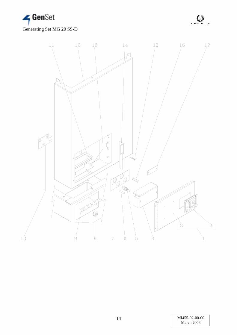
N° Ordering N° Denomination1 129843/Z Output door assembly2 112178 Knob3 129843 Output door4 116121 Output cover5 110247 Output insulator6 110711 8x50 tierod7 131463 Aluminium front plate for output8 117623 Screw9 117345 Wire holder plate
10 132513 Reinforcement11 117331 Rubber wire holder support12 134200/R Right front panel13 117330 Rubber wire holder14 129850 Opened door support15 9881 Safety switch16 102740 Stud17 141885 Single phase output aluminium plate

Generating Set MG 20 SS-D
16 MI455-02-00-00March 2008
Generating Set MG 20 SS-D
17 MI455-02-00-00March 2008
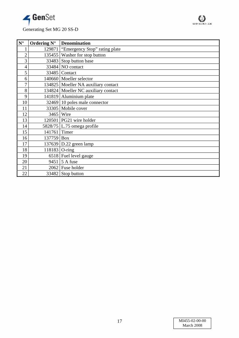
N° Ordering N° Denomination1 129871 “Emergency Stop” rating plate2 135455 Washer for stop button3 33483 Stop button base4 33484 NO contact5 33485 Contact6 140660 Moeller selector7 134825 Moeller NA auxiliary contact8 134824 Moeller NC auxiliary contact9 141819 Aluminium plate
10 32469 10 poles male connector11 33305 Mobile cover12 3465 Wire13 120501 PG21 wire holder14 5828/75 L.75 omega profile15 141761 Timer16 137759 Box17 137639 D.22 green lamp18 118183 O-ring19 6518 Fuel level gauge20 9451 5 A fuse21 2062 Fuse holder22 33482 Stop button

Generating Set MG 20 SS-D
18 MI455-02-00-00March 2008
Generating Set MG 20 SS-D
19 MI455-02-00-00March 2008
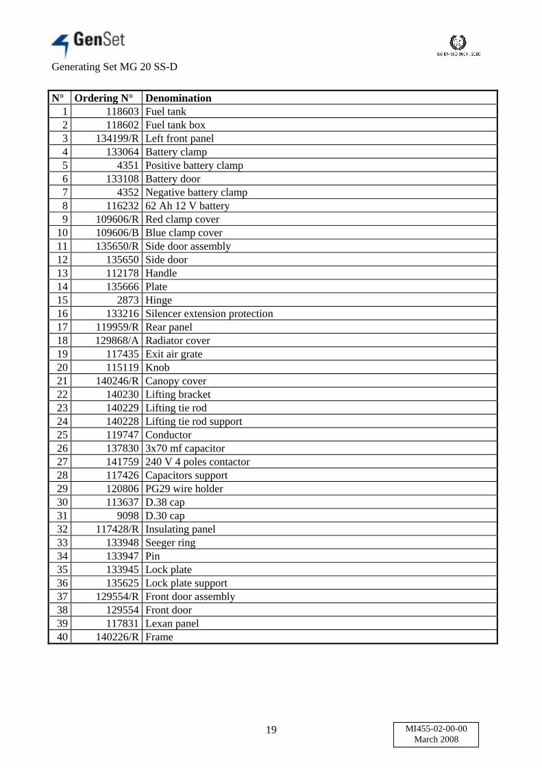
N° Ordering N° Denomination1 118603 Fuel tank2 118602 Fuel tank box3 134199/R Left front panel4 133064 Battery clamp5 4351 Positive battery clamp6 133108 Battery door7 4352 Negative battery clamp8 116232 62 Ah 12 V battery9 109606/R Red clamp cover
10 109606/B Blue clamp cover11 135650/R Side door assembly12 135650 Side door13 112178 Handle14 135666 Plate15 2873 Hinge16 133216 Silencer extension protection17 119959/R Rear panel18 129868/A Radiator cover19 117435 Exit air grate20 115119 Knob21 140246/R Canopy cover22 140230 Lifting bracket23 140229 Lifting tie rod24 140228 Lifting tie rod support25 119747 Conductor26 137830 3x70 mf capacitor27 141759 240 V 4 poles contactor28 117426 Capacitors support29 120806 PG29 wire holder30 113637 D.38 cap31 9098 D.30 cap32 117428/R Insulating panel33 133948 Seeger ring34 133947 Pin35 133945 Lock plate36 135625 Lock plate support37 129554/R Front door assembly38 129554 Front door39 117831 Lexan panel40 140226/R Frame

Generating Set MG 20 SS-D
20 MI455-02-00-00March 2008
Generating Set MG 20 SS-D
21 MI455-02-00-00March 2008
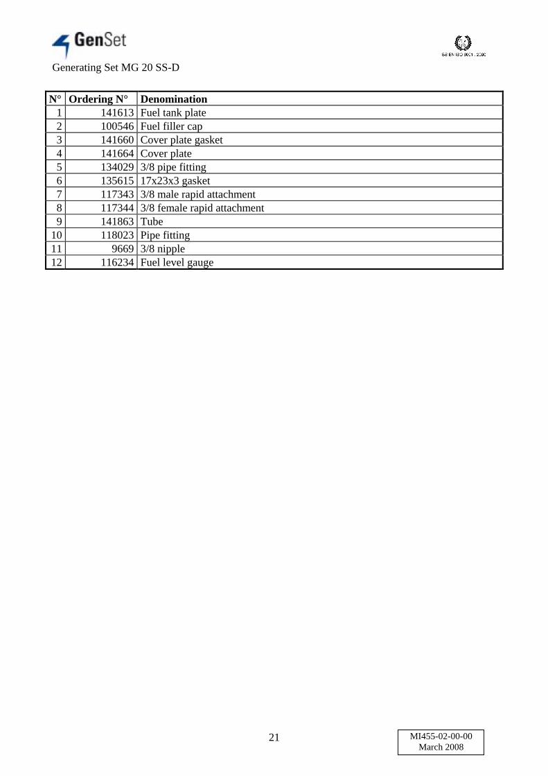
N° Ordering N° Denomination1 141613 Fuel tank plate2 100546 Fuel filler cap3 141660 Cover plate gasket4 141664 Cover plate5 134029 3/8 pipe fitting6 135615 17x23x3 gasket7 117343 3/8 male rapid attachment8 117344 3/8 female rapid attachment9 141863 Tube
10 118023 Pipe fitting11 9669 3/8 nipple12 116234 Fuel level gauge
Generating Set MG 20 SS-D
22 MI455-02-00-00March 2008
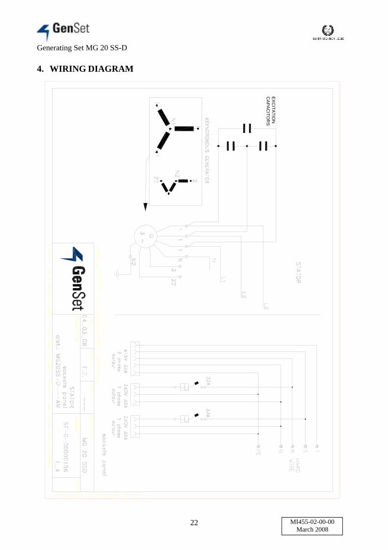
4. WIRING DIAGRAM
EXC
ITATIO
NC
APA
CITO
RS

Generating Set MG 20 SS-D
23 MI455-02-00-00March 2008

Generating Set MG 20 SS-D
24 MI455-02-00-00March 2008
TA CT35
SPEC
IAL
RE
MO
TE P
ANEL
CO
NN
ECTO
R
R1: A
UX
. + RE
LAY (12V
DC
);R
2: GLO
W P
LUG
RELA
Y (12V
DC
);R
3: STAR
T RELA
Y (12VD
C );
R4: C
ON
TACTO
R R
ELAY
-AU
TO M
OD
E (12VD
C 133207+116805);
R5: C
ON
TACTO
R R
ELAY
-MA
N. M
OD
E (12V
DC
133207+116805);R
6: PU
RA
DY
NE R
ELAY
(12VD
C);
K1: C
ON
TAC
TOR
(coil 240VA
C, Ith 70A
)TA
B: AM
P. TR
AN
SFO
RM
ER
100/5;D
: 1N4007 diode;
Sf: safety sw
itch.
GE
: AU
TO/M
AN
selector in MA
N & M
P24 in M
AN: G
enerator start/stop comm
and via Key sw
itch on front panel; pow
er to the load by [230V ON
] / [230V O
FF] buttons.G
E: A
UTO
/MA
N selector in A
UTO
& M
P24 in AU
TO: G
enerator start/stop comm
and via S
PE
CIAL R
EM
OTE P
ANE
L; [230V O
N] / [230V
OFF] buttons disabled.
8586
0illevel
Open
door
R6
R2
R130 87
R230 87
DC
SUPP
LY
MP 24
30 87
R6
IGN
ITION
KEY SW
ITCH
V
R3 8586
A
ON
EMER
GEN
CY
STOP
BUTTO
NR
330 87
FUEL
R1
858686 85
ELRB
YPASS
Rem
otepanel(M
P24
Auto)
R4
Manual
mode
only240VO
FF
240VO
N
R5
N-T
240V 15kV
A1 P
HA
SEO
UTPU
T
1 52 3 4 87 96 10
R5
K1
Trippingcoil

Generating Set MG 20 SS-D
25 MI455-02-00-00March 2008
SP
EC
IAL R
EM
OTE
PA
NE
L: S
elect the operational mode by the M
OD
E S
ELE
CTO
R:
1: TIME
R: the G
E autom
atically start (via timer), runs w
ith load than autom
atically stops (via timer).
The cycle is adjusted by timer settings.
2: RE
MO
TE S
TAR
T/STO
P: the operator can start the G
E by sw
itching the S
TAR
T /STO
P selector in S
TAR
T position. The GE
will take the load
automatically . The operator can stop the G
E by switching the STAR
T /STOP
selector in STO
P position.
SUPPLY DC -
SUPPLY DC +
GE breaker ON
REMOTE START
EMER. STOP
Fuel level
SP
EC
IAL R
EM
OTE
PA
NE
Lconnection cable
21 4 53 86 7 9 10
62
8
GE
breakerO
NFU
EL
1
EM
ER
GE
NC
YS
TOP
BU
TTON
4
AB
1TIM
ER
35
7
MO
DE
SE
LECTO
R:
1: TIME
R;
2: MAN
UAL
STA
RT/STO
P.
SP
EC
IAL
RE
MO
TEP
ANEL
Active only in M
ANU
AL STAR
T/STOP m
ode;M
OD
E S
ELECTO
R in
position 2.
2
START/STO
P
Generating Set MG 20 SS-D
26 MI455-02-00-00March 2008
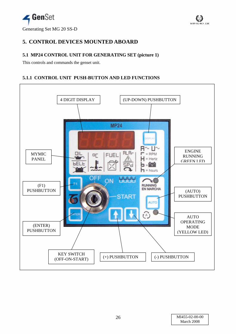
5. CONTROL DEVICES MOUNTED ABOARD
5.1 MP24 CONTROL UNIT FOR GENERATING SET (picture 1)This controls and commands the genset unit.
5.1.1 CONTROL UNIT PUSH-BUTTON AND LED FUNCTIONS
4 DIGIT DISPLAY (UP-DOWN) PUSHBUTTON
MYMICPANEL
(F1)PUSHBUTTON
(ENTER)PUSHBUTTON
ENGINERUNNING
GREEN LED
(AUTO)PUSHBUTTON
AUTOOPERATING
MODE(YELLOW LED)
KEY SWITCH(OFF-ON-START) (+) PUSHBUTTON (-) PUSHBUTTON

Generating Set MG 20 SS-D
27 MI455-02-00-00March 2008
MP24 features Engine and Generating Set (hereinafter GEN-SET) control and monitoring. TheMP24 provides visual indication by means of LEDs and Display. It features OFF-AUTO-MANoperating modes. The display gives Messages for the following failures: Low Fuel Level,Emergency Alarm, Low Oil Pressure, High Temperature, High/Low Battery Voltage, BeltBreak/Charger Failure, Over/Under Frequency, Fail to start, Alternator Failure, Over/UnderVoltage, Over/Under Speed, Overload.The following measurements are obtained on the front panel by using the (DISPLAY) pushbutton:Generator Voltage/Current/Frequency, Battery Voltage, Hours Meter, Charger Alternator Voltageand R.P.M.The MP24 provides static outputs for START, STOP, ALARM (or GENERATOR CONTACTOR),FUEL SOLENOID and PRE-GLOW.The MP24 features 31 programmable parameters, measurements calibration; the front panelincludes 6 pushbuttons, 2 LEDs and a 4-digits DISPLAY.
5.1.2 DAS, AUTOMATIC ENGINE SHUT OFFSafety device mounted aboard. It shuts off the engine automatically to avoid possible damage, incase of one of the following irregularities:(OIL) Low oil pressure:Indication of Low Oi1 Pressure alarm. The input is connected to an external normally closedcontact (input #3). The Oil Pressure Switch is by-passed by means of the [P.25] timing.(°C) High engine temperature:Indication of High Temperature alarm. This input (terminal #4) Is connected to a normally open orclosed temperature switch. The polarity of the contact is selected by means of a code in the [P.18](option [n.o.] or [n.c.]). The alarm is bypassed 1 second.(O.SPd.) OverSPEED:The source of the alarm is derived from the Pick-UP (or “W” of the Charger Alternator). Theparameters [P.22]-[P.23] allow full monitoring of the speed. The message flashes to indicate Over(1 second by-pass). To know the Speed that caused the failure push the [F1] pushbutton.(U.SPd.) UnderSPEED:The source of the alarm is derived from the Pick-UP (or “W” of the Charger Alternator). Theparameters [P.21]-[P.22] allow full monitoring of the speed. The message flashes to indicate UnderSpeed shut down (6-second timing by-pass). To know the Speed that caused the failure push the[F1] pushbutton.(bELt) Belt break:The alarm is enabled by means of the (on) code into [P.15] There is a ‘Belt Break’ alarm when theGenerator voltage is within the settings but the output voltage of the Charger Alternator is lowerthan the threshold of the [P.3]. A 20-second delay prevents false trigger of the alarrn. The [OFF]code, inserted in the [P.15], inhibits the alarm.(ALAr) Emergency alarm:This is an indication of External Emergency Stop (input #5). The MP24 stops the engine withoutdelay. The polarity of the EMERGENCY ALARM contact is programmed into the [P.19] (option[n.o.] or [n.c.]).(FUEL) Fuel alarm:This is an indication of Low Level Fuel in the tank (input#6).(FAIL) Starting failure:This alarm is aciivated if the engine does not start after acomplete starting cycle (see settings of the parameters [P.2]-3]-4]-5]) or after a MANUAL startingcycle.

Generating Set MG 20 SS-D
28 MI455-02-00-00March 2008
(E 04) Generator failure:This message will be displayed if the Voltage or the Frequency of the alternator lacks for 150seconds after the engine has been started. The alarm monitoring is disabled if the [ P.12] containsthe [OFF] code or the MP24 is in MANUAL operating mode.(Hi H) Over frequency:The Over Frequency setting is programmed into the [P.9]. The protection is delayed 2 seconds. TheMP24 shuts down the engine. To know the Frequency that caused the failure push the [F1]pushbutton.(Lo H) Under frequency:The Under Frcquency setting is programmed into the [P.8]. The protection is delayed by 6 seconds.The MP24 shuts down the engine. To know the Frequency that caused the failure push the [F1]pushbutton.(Hi U) Over Voltage:If the voltage rises above the [P.7] setting for more than 2 seconds, the Over-Voltage alarmenergises and the engine shuts down. To know the Voltage that caused the failure push the [F1]pushbutton.(Lo U) Under voltage or Short circuit, the alarm energises if:- the voltage drops under the [P.6] setting for more than 6 seconds- the voltage drops under the [P.6] setting (minus 20%) for more than 1 secondTo know the Voltage that caused the failure push the [F1] pushbutton.(XX.X) Battery voltage alarm:The alarm settings are automatically fixed to 118/15.0V for a 12V battery or 23,6/30.0V for a 24Vbattery. The alarm is delayed by 120 seconds and is ignored during Pre-Glow and starting cycles.The engine does not shut down and the user can select other display menus by using the [UP-DOWN] pushbutton.
Generating Set MG 20 SS-D
29 MI455-02-00-00March 2008
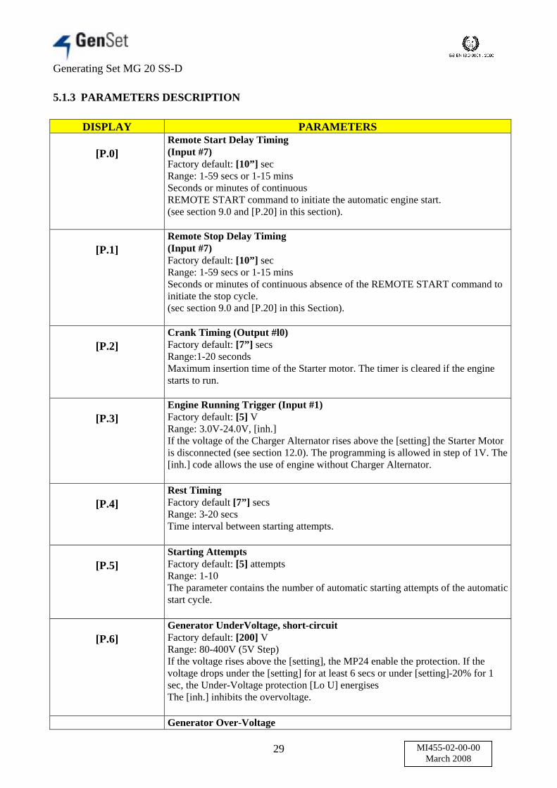
5.1.3 PARAMETERS DESCRIPTION
DISPLAY PARAMETERS
[P.0]Remote Start Delay Timing(Input #7)Factory default: [10”] secRange: 1-59 secs or 1-15 minsSeconds or minutes of continuousREMOTE START command to initiate the automatic engine start.(see section 9.0 and [P.20] in this section).
[P.1]Remote Stop Delay Timing(Input #7)Factory default: [10”] secRange: 1-59 secs or 1-15 minsSeconds or minutes of continuous absence of the REMOTE START command toinitiate the stop cycle.(sec section 9.0 and [P.20] in this Section).
[P.2]Crank Timing (Output #l0)Factory default: [7”] secsRange:1-20 secondsMaximum insertion time of the Starter motor. The timer is cleared if the enginestarts to run.
[P.3]Engine Running Trigger (Input #1)Factory default: [5] VRange: 3.0V-24.0V, [inh.]If the voltage of the Charger Alternator rises above the [setting] the Starter Motoris disconnected (see section 12.0). The programming is allowed in step of 1V. The[inh.] code allows the use of engine without Charger Alternator.
[P.4]Rest TimingFactory default [7”] secsRange: 3-20 secsTime interval between starting attempts.
[P.5]Starting AttemptsFactory default: [5] attemptsRange: 1-10The parameter contains the number of automatic starting attempts of the automaticstart cycle.
[P.6]Generator UnderVoltage, short-circuitFactory default: [200] VRange: 80-400V (5V Step)If the voltage rises above the [setting], the MP24 enable the protection. If thevoltage drops under the [setting] for at least 6 secs or under [setting]-20% for 1sec, the Under-Voltage protection [Lo U] energisesThe [inh.] inhibits the overvoltage.
Generator Over-Voltage

Generating Set MG 20 SS-D
30 MI455-02-00-00March 2008
[P.7] Factory default: [270] VRange: 110-550V or [inh.](5V Step)If the Generator voltage rises above the [setting] for at least 2 seconds, the MP24will energise the over voltage protection [Hi U] (see section 4.0) and stops theengine.The [inh.] inhibits the overvoltage.
[P.8]Generator Under-FrequencyFactory default: [47] Hz[inh.] to 99Hz ([inh.]=disables the under frequency)The protection is delayed by 6 seconds. The MP24 shuts down the engine and thedisplay will show [Lo H] (see section 4.0).
[P.9]Generator Over-FrequencyFactory default: [56] Hz45 to [inh.] ([inh.]=disables the over frequency)The protection is delayed by 2 seconds. The MP24 shuts down the engine and thedisplays [Hi H] (see section 4.0).
[P.10]Current Transformer SizeFactory default: [100]/5The range is 10/5 up to 1000/5The settings are allowed only in steps of 10.
[P.11]Generator Overload SettingFactory default: [inh.] (inhibited)Range: [inh.] to 1000 AThe MP24 shuts down the engine after a delay of 6 secs and shows the message[E04]. The settings are allowed in steps of 1A (CT 10/5 up to 100/5) and 10A (CT100/5 up to 1000/5).
[P.12]Generator Failure AlarmFactory default: [ON]Selection: [on] or [OFF]The code [on] enables the generator failure alarm. The alarm energises if thevoltage (or the frequency) is lower than the UnderV/Hz settings for more than 150seconds. The MP24 shows the [E04] message and the engine will shut down.
[P.13]Glow Plugs/Choke Control(Output #11)Factory default: [10”] (seconds)Range: 1 to 99 secsThe MP24 energises the output #11 for the programmed time. The [P.14] controlsthe operating mode of the output #11(Pre-Glow or Choke section 7.0 and 8.0)
[P.14]Output ControlFactory default: [2] (none)The following possibilities are available:[0] None, [1] Choke Control (section 8.0), [2] Glow Plugs Control[3] Choke Control (section 8.0)
[P.15]Belt Break ControlFactory default: [ON] (inhibited)

Generating Set MG 20 SS-D
31 MI455-02-00-00March 2008
Selection: [on] or [OFF]The Belt Break (or Charger Alternator failure) alarm is indicated by means of themessage [bELt] (see section 4.0)
[P.16]Stop Solenoid Timing(Output #12)Factory default: [10”] secsRange: 2-99 secsDuration of the Stop cycle (output #12). The stop solenoid will remain energisedfor the programmed time.
[P.17]Alarm Output Timing(Output #2)Factory default: [inh.][inh.]-59 secs 1-15 mins and [cont]Time-out of the alarm output #2. The code [cont] disables the time-out and thealarm remains energised until the OFF operating mode will be selected. The [inh.]mode enables the use of the external contactor(see parameter [P.28]).
[P.18]Temperature Switch (INPUT #4)Factory default: [n.o.] (normally open)Selection: [n.o.] or [n.c.][n.o.] normally open contact: the engine shuts down if the contact closes.[n.c.] normally closed contact: the engine shuts down if the contact opens.
[P.19]ALARM Control (INPUT #5)Factory default: [n.o.] (normally open)Selection: [n.o.] or [n.c.][n.o.] normally open contact: the engine shuts down if the contact closes.[n.c.] normally closed contact: the engine shuts down if the contact opens.
[P.20]Remote Start (INPUT #7)Factory default: [n.o.] (normally open)Selection: [n.o.] or [n.c.][n.o.] normally open contact: the engine starts if the contact closes.[n.c.] normally closed contact: the engine starts if the contact opens.
[P.21]Under Speed settingFactory default: [inh.][Inh.] or 100-4000 r.p.m.The MP24 by-passes the protection by 6 seconds to avoid false trigger action.The [Inh.] code (setting <100 r.p.m.) disables the Under Speed shut down.
[P.22]Over Speed settingFactory default: [inh.]100-4000 rpm or [Inh.].The MP24 provides one second bypass delay. The [Inh.] code (>4000 r.p.m.)disables the Over Speed shut down.
[P.23]Number of Teeth of the FlywheelFactory default: [Inh.][Inh.] or 1-500 teeth.

Generating Set MG 20 SS-D
32 MI455-02-00-00March 2008
The [Inh.] code (setting <1 ) disables thereading of the Speed (section 3.0), theOver/Under Speed shut downs and theCrank OFF action.
[P.24]Crank OFFFactory default: [Inh.]Crank Termination setting: 100-800 rpmThis speed threshold terminates crank. One second delay is added to avoid falsetermination. The allowed range is 100 upto 800 R.P.M. The code [Inh.] inhibits thecrank termination.
[P.25]Low Oil Pressure Alarm By-PassFactory default: [ 6"] secsRange: 0-99 secsBy-Pass Delay to ignore the Oil Pressure(input #3) during the engine starting cycle.The input requires normally closed contact.
[P.26]Automatic Periodic Test CycleFactory default: [inh.] (inhibited)Range: [inh.]-99 daysThis is the interval time between theautomatic periodic tests of the engine. Thecode [inh.] disables the Automatic PeriodicTest (see section 22.0).
[P.27]Automatic Engine Test DurationFactory default: [ 5'] minsRange: 1-99 minutesThis is the duration of the automatic engine test (see section 22.0).
[P.28]Generator warm-up timingFactory default: [ 10”] secsRange [inh.]-15 minutes ([inh.]=No warmup)Active only when [P17]= [inh.] theALARM output is used to drive the GEN-SET contactor.
[P.29]Generator cooling timingFactory default: [ 30”] secsRange [inh.]-15 minutes ([inh.]=No warmup)Active only when [P17]= [inh.] theALARM output is used to drive the GEN-SET contactor.

Generating Set MG 20 SS-D
33 MI455-02-00-00March 2008
[P.30]Enabling frequency Revolution CounterFactory default: [ inh.]Range: 2 = alternator 2 poles 3000 turns 4 = alternator 4 poles 1500 turnsEnables the reading of the revolution counter motor drawing the value from thefrequency of the alternator.
[P.31]Planning Fuel End AlarmFactory default: [1’]Range: [99’ - 1’ - inh.][inh.] = only optic signaling, no motor stop[from 1’ to 99’] = delaty for motor stop
5.2 RD2 EARTH LEAKAGE CIRCUIT BREAKER
The unit is equipped with an RD2 earth leakage circuit breaker capable of ensuring user protectionin case of accidental contact with live parts or failure of the insulation system of connected users.If an earth leak current occurs (differential current), the toroidal transformer supplies a signal to theRD2 differential relay, which processes it and compares it with the set sensitivity value. When thisthreshold level is exceeded, the set delay is enabled and then the alarm contact is tripped.
On-panel controls1- Green LED “ON” : power ON2- Red LED “TRIP” : alarm status the connection between the toroidal transformer and thedifferential relay is continuously controlled by the latter - if theconnection is interrupted, the differential relay goes into “alarm” status.3- The “TEST” push-button simulates a fault inside the differential relay: when the button ispressed, the differential relay must changeover to alarm status.4- The “RESET” push-button returns the differential relay to its initial “non alarm” status.5- To select tripping steps I.6- To select tripping steps in seconds.
WARNING! Apply only to authorised Gen Set centres for technical service on electricalcomponents.
• Before connecting a load to sockets on the front panel of the unit, make sure that the generatorsupplies enough power for the tools that are connected.
Beware: electric motors’ starting current requirements are considerably higher than ratedfull load values.
• Before connecting a load to single phase and/or three phase sockets, make sure that the circuitbreakers are open.• At the end of work, before removing plugs from panel sockets, open the circuit breakers.• Connect loads to generator’s sockets only by using cables of suitable size and in good conditions,with plugs fitted for the sockets on the panel. Do not use adapters.
WARNING! This device does not exempt the user from checking the engine oil level by usingthe dipstick located on the left side of the unit. This check must be done daily.

Generating Set MG 20 SS-D
34 MI455-02-00-00March 2008
Setting selection
5.3 EMERGENCY STOP BUTTON
The power generator is equipped with an EMERGENCY STOP device to stop immediately thegenerator in case of danger. The device is actuated by pressing the red pushbutton located on thefront of the generator. The engine stops. To disengage the emergency stop device, rotate the redpushbutton clockwise until it pops out.
WARNING! The generator cannot be restarted if the emergency stop device is activated.
5.4 OPEN DOOR
The machine has been equipped with a “Open door” protection device. Take note that the generatorwill not operate or start if the indicated doors are open.
5.5 BATTERY ISOLATOR SWITCH
This device placed on the left side of the machine isolates starting system to prevent illegal use ofmachine or flattening the battery. Please remember to switch off the battery and remove the keyfrom the switch when the machine is not in use. Turn the key clockwise to connect the battery.Turn the key anticlockwise to disconnect the battery, now is possible to remove the key.
WARNING! The battery must be not switched off when the engine is running.

Generating Set MG 20 SS-D
35 MI455-02-00-00March 2008
6. EARTHING THE POWER GENERATOR (picture 1)
Before starting the generator, connect it to earth by using the earth connection provided (1) and acable of suitable size without interposing switches or other devices capable of breaking theelectrical connection to earth. The earth system must conform to CEI 64-8 regulations.
WARNING! Do always connect the power generator to earth. Check that the cables are inperfect condition.
Picture 1
Batteryon
Batteryoff

Generating Set MG 20 SS-D
36 MI455-02-00-00March 2008
7. STARTING THE MACHINE
7.1 PROCEDURE FOR MANUAL STARTING (WITHOUT REMOTE CONTROL)(picture 2 page 37)
To start the generator proceed as follows:(a). Make sure that the generator is correctly positioned.(b). Use the oil dipstick located on the right side of the machine to check that the engine has beenfilled with the right oil quantity. If it doesn’t, then fill as described in this manual.(c). Check if the radiator contains the right quantity of coolant. If doesn’t fill the radiator asdescribed in this manual. Check the right coolant level.(d). Make sure that the battery insulator switch is in “ON” position.(e). Make sure that no load is connected to the machine. It is recommended that the main breakerswitch (15) is disengaged.(f). Make sure that the differential relay (E.L.R.) (14) has been adjusted for the required sensitivity.Make sure that the By-pass key (2) is in the position required by the application. The coming on ofthe By pass warning light (4) indicates that the E.L.R. protection is excluded from the generatingplant.(g). Switch the DC Supply selector (12) to the “ON” position.(h). Switch the “REMOTE CONTROL ON/OFF” selector (3) to the “OFF” position.(i). Turn the starting key (6) to the “ON” position; the MP24 illuminates all LED and Display.(l). The Display (5) shows the flashing message [uuuu]; the MP24 is counting the PRE-GLOWtime.(m). When the Display shows the flashing message [StA-] turn the starting key (6) in “START”position (momentary position with spring-loaded return) until engine starts.NOTE: MP24 shows the flashing prompt message [StA-] for 20 seconds. After this time, if theengine does not start, the MP24 shuts down the FUEL SOLENOID and displays the message[FAIL]. To clear the alarm it is necessary to turn the starting key in “OFF” position.(n). To press the push button “ ON” (8); the green light (9) will energise.(o). Connect the load.

Generating Set MG 20 SS-D
37 MI455-02-00-00March 2008
Picture 2
AUT

Generating Set MG 20 SS-D
38 MI455-02-00-00March 2008
8. USING THE REMOTE CONTROL IN MANUAL MODE (picture 2 page 37)
The user can start and stop the machine manuallyThe following operation must be done on the machine when you have to start the job.
(a). Make sure that the generator is correctly positioned.(b). Use the oil dipstick located on the right side of the machine to check that the engine has beenfilled with the right oil quantity. If it doesn’t, then fill as described in this manual.(c). Check if the radiator contains the right quantity of coolant. If doesn’t fill the radiator asdescribed in this manual. Check the right coolant level.(d). Make sure that the battery insulator switch is in “ON” position.(e). Make sure that no load is connected to the machine. It is recommended that the main breakerswitch (14) is disengaged.(f). Make sure that the differential relay (E.L.R.) (13) has been adjusted for the required sensitivity.Make sure that the By-pass key (2) is in the position required by the application. The coming on ofthe By pass warning light (4) indicates that the E.L.R. protection is excluded from the generatingplant.(g). Switch the DC Supply selector (11) to the “ON” position.(h). Switch the “REMOTE CONTROL ON/OFF” selector (3) to the “ON” position.(i). Turn the starting key (6) to the “ON” position; the MP24 illuminates all LED and Display.(l). The Display (15) shows the flashing message [uuuu]; the MP24 is counting the PRE-GLOWtime.(m). Press the “AUTO” button (17).NOTE: Before the starting the Display (15) shows the flashing message [uuuu]; the MP24 is counting thePRE-GLOW time.
ON THE REMOTE CONTROL
(a). Switch the MODE selector (16) to the “MANUAL” position.(b). Using the start and stop switch (17) you can decide to start and stop the machine. The contactorswitch will be closed or opened by the MP24.
WARNING! In case of short circuit, over load or fault to the groud the main breaker will tripoff and the user have to remove the fault and than he has to close the main breaker manually.

Generating Set MG 20 SS-D
39 MI455-02-00-00March 2008
9. USING THE REMOTE CONTROL IN TIMER MODE (picture 2 page 37)
The timer will start and stop the machine automaticallyThe following operation must be done on the machine when you have to start the job.
(a). Make sure that the generator is correctly positioned.(b). Use the oil dipstick located on the right side of the machine to check that the engine has beenfilled with the right oil quantity. If it doesn’t, then fill as described in this manual.(c). Check if the radiator contains the right quantity of coolant. If doesn’t fill the radiator asdescribed in this manual. Check the right coolant level.(d). Make sure that the battery insulator switch is in “ON” position.(e). Make sure that no load is connected to the machine. It is recommended that the main breakerswitch (14) is disengaged.(f). Make sure that the differential relay (E.L.R.) (13) has been adjusted for the required sensitivity.Make sure that the By-pass key (2) is in the position required by the application. The coming on ofthe By pass warning light (4) indicates that the E.L.R. protection is excluded from the generatingplant.(g). Switch the DC Supply selector (11) to the “ON” position.(h). Switch the “REMOTE CONTROL ON/OFF” selector (3) to the “ON” position.(i). Turn the starting key (6) to the “ON” position; the MP24 illuminates all LED and Display.(l). The Display (15) shows the flashing message [uuuu]; the MP24 is counting the PRE-GLOWtime.(m). Press the “AUTO” button (17).NOTE: Before the starting the Display (15) shows the flashing message [uuuu]; the MP24 is counting thePRE-GLOW time.
ON THE REMOTE CONTROL
(a). Switch the MODE selector (16) to the “TIMER” position.(b). The timer will start and stop the machine using the adjustment. The contactor switch will beclosed or opened by the MP24.
WARNING! In case of short circuit, over load or fault to the groud the main breaker will tripoff and the user have to remove the fault and than he has to close the main breaker manually.
9.1 TIMER SETTING
Default setting:At 07:00 the machine would automatically start.At 08.00 the machine would automatically stop.At 17:30 the machine would automatically start.At 18:30 the machine would automatically stop.

Generating Set MG 20 SS-D
40 MI455-02-00-00March 2008
10. STOP PROCEDURES
10.1 PROCEDURE FOR MANUAL SWITCHING OFF (picture 2 page 37)
(a). To press the push button “ OFF” (13); the green light (9) will switch off.(b). Disconnect the load.(c). Turn the starting key (6) to the “OFF” position.(d). Switch the DC Supply key (13) on the OFF position.Switching off the machine, it disengages the main circuit breaker (15) automatically.
WARNING! If none emergency situation occurs, don’t use the emergency stop button to stopthe machine.
10.2 PROCEDURE FOR REMOTE CONTROL SWITCHING OFF (picture 2 page 37)
In TIMER MODE the machine would automatically stopIn MANUAL MODE switch the selector (17) to the “STOP” position.

Generating Set MG 20 SS-D
41 MI455-02-00-00March 2008
11. GENERAL USE INSTRUCTIONS
Read the instructions carefully; proceed according to the regulations in use in the country where the machine will operate.
11.1 TRANSPORTATION
The machine must be fixed carefully to the motor vehicle if it has to be moved to the place of use. Raise the machine using the lifting eye if the model foresees it;otherwise, lift it using a forklift, taking care that the weight is well balanced on the two forks. It is advised not to stay in the range of action during these operations;furthermore we suggest not to keep the machine hung up for long.If the machine is delivered without the wheels on, mount them before switching the machine on.During the normal use of the machine mounted on wheels (in a building yard or anywhere), the operator must ascertain that the machine is weel placed in order to avoidunforeseen displacement.
11.2 CAUTION
Be careful: the generating set or the welder is furnished WITHOUT lube oil. Provide the machine with “10 W 40” multigrade oil indicated for temperatures from - 20° Cto 40° C in the quantity indicated in the engine SPECIFICATION section.Be careful: if the machine is fitted with a water cooled engine fill the radiator circuit with a solution made up by 50% water and 50% antifreeze liquid inthe quantityindicated i the engine SPECIFICATION section.Be careful: the generating set is furnished with flat battery and without acid. Fill it using sulphuric acid in a 30% - 40% concentrated solution up to the complete coveringof the elements. During this operation, we suggest the operator to use the gloves; the accidental contact with the sulphuric acid solution must be washed up immediatelywith cold water and, if necessari, a doctor must be consulted.Be carefull: don’t disconnect battery cables when the engine runs. This coud result in serious damages to the machine.Be carefull: BEFORE OPERATING THE MACHINE the neutral, or the equivalen winding point, MUST be connected effectively to the earth (without any switch or otherdevice that may interrupt the electric connection) from the earth clamp available on the machine, and identified by the symbol:
Be carefull: for normal transportation, follow the instructions as specified in the TRASPORTATION section. Make sure that the machine doesn’t overturn in order toavoid spill of acids from the battery.
11.3 RUNNING IN
For the first 50 hours of operation of the machine do not employ more than 70% of the maximum power indicated in the technical specifications. In this way, a properengine running in is guaranteed.
11.4 STARTING AND WORKING
Make the earth connection (see the USE INSTRUCTIONS).If the machine model IS NOT equipped with a earth leakege circuit breaker the available socket is intended ONLY for connecting the machine to a switch board equippedwith all protection devices imposed by current law regulations.Check the perfect state and efficiecy of the cables.Make sure that all the switches, electric connections and regulations are inthe right position for the starting (see USE INSTRUCTIONS and CONTROL PANELSDESCRIPTIONS).While welding, eyes and body must be protected by gloves, maskes Use the machine in well ventilated places, taking care that the exhaust gas and the welding smokeseventually produced (where welders are used) do not stagnate. Keep the machine away from walls or other kind of obstacles i order to avoid air or gas recycling. If themachine is employed in closed places, use aspirators in order to guarantee a proper air recycling.While welding, eyes and body must be potected by gloves, maskes and proper clothes.The fuel refill must not be made while smoking or close to flames. This operation must be done when the engine is switched off.Do not fill the tank at its maximum level and clean up the fuel eventually overflowed.Check daily if there is loss of fuel or lubrificating oil on the ducts or on the engine.For machines provided zith liftable canopy insert the foreseen security sistems in order to avoid injures caused by an unexpected closure.
11.5 FORBIDDEN USE
Do not connect the machine to the commercial electric network.Do not work close to inflammable materials or where there are explosive gas and vapours.Do not work in narrow and badly ventilated places.Do not work without using the protections placed in their proper positions and in perfect conditions.Do not touch the exhaust muffler and the parts of the engine next to it.Do not make service operations while the engine is running.Any service made on the electric parts must be done when the engine is stopped and by specialized technicians.Keep away from the moving parts of the engine while working and do not approach the machine with free and too long clothes.
11.6 SERVICE AND CLEANING
We suggest a frequent cleaning of the machine since the presence of dirt can compromise the efficiency of the machine. The frequency of this operation tightly depends onthe place where the machine is used. We advise, anyway. to pay special care to the service of:OIL LEVEL, OIL FILTER, AIR FILTER, COOLING LIQUID LEVEL, COOLING LIQUID LEVEL, HEAT EXCHANGER, VENTILATION DUCTS AND INTAKES,BATTERYConsult the ENGINE USE AND SERVICE manual and the SPECIFICATION section to know how and when it is useful to do it. The extraordinary service operations notmentioned hereabove require the aid of specialized technicians (see the assistance centre list).
11.7 ADJUSTMENT AND REGULATIONS
All the necessary controls are located on the main control panel and they are properly explained in the section FRONT PANEL DESCRIPTIONS.We advise the operator against tempering with the engine or the electric part if not specialized.Be careful: eventual modifications of the normal parameters originally foressen, can compromise the reliability of the machine.

Generating Set MG 20 SS-D
42 MI455-02-00-00March 2008
11.8 TEMPORARY STANDSTILL
If the machine has to be stopped for a long period (more than one year), we suggest to leave the motor oil and the fuel in and the water in the radiator in order to avoidoxydizing effects.When the machine turns to work again, the liquids must be replaced, the battery must be charged; the belts and their statem the pipes, the rubber hoses and their resistancemust be checked and a visual inspections of the electric connections must be done.
11.9 SCRAPPING
In order to preserve the environnement, it is advised to dispose of the oil, the fuel and the bettery that will be destroyed in proper places and ccording to the current laws.For the complete range of the materialsm see the list below:FERROUS MATERIALS:steel, cast iron, aluminium, copper, brass are udes in the bearing structure of engine, alternator, transformers, etc.PLASTIC MATERIALS:rubber, bakelite, epovit, lexan are used for the instruments, engine pipes, junction boxes and connectors, fuel tank, fuel cap, wheels, antivibration damper, condenserhousing, fans, belts, filters and hoses.ELECTRONIC MATERIALS:various components, diodes, resistances, electronic panels.VARIOUS MATERIALS:rock woll, sound proofing materials.LIQUIDS:fuel, gasoline, cooling liquids, battery acid.
Generating Set MG 20 SS-D
43 MI455-02-00-00March 2008
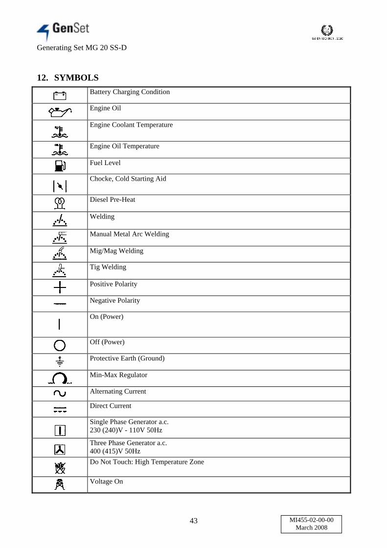
12. SYMBOLSBattery Charging Condition
Engine Oil
Engine Coolant Temperature
Engine Oil Temperature
Fuel Level
Chocke, Cold Starting Aid
Diesel Pre-Heat
Welding
Manual Metal Arc Welding
Mig/Mag Welding
Tig Welding
Positive Polarity
Negative Polarity
On (Power)
Off (Power)
Protective Earth (Ground)
Min-Max Regulator
Alternating Current
Direct Current
Single Phase Generator a.c.230 (240)V - 110V 50Hz
Three Phase Generator a.c.400 (415)V 50HzDo Not Touch: High Temperature Zone
Voltage On
Generating Set MG 20 SS-D
44 MI455-02-00-00March 2008
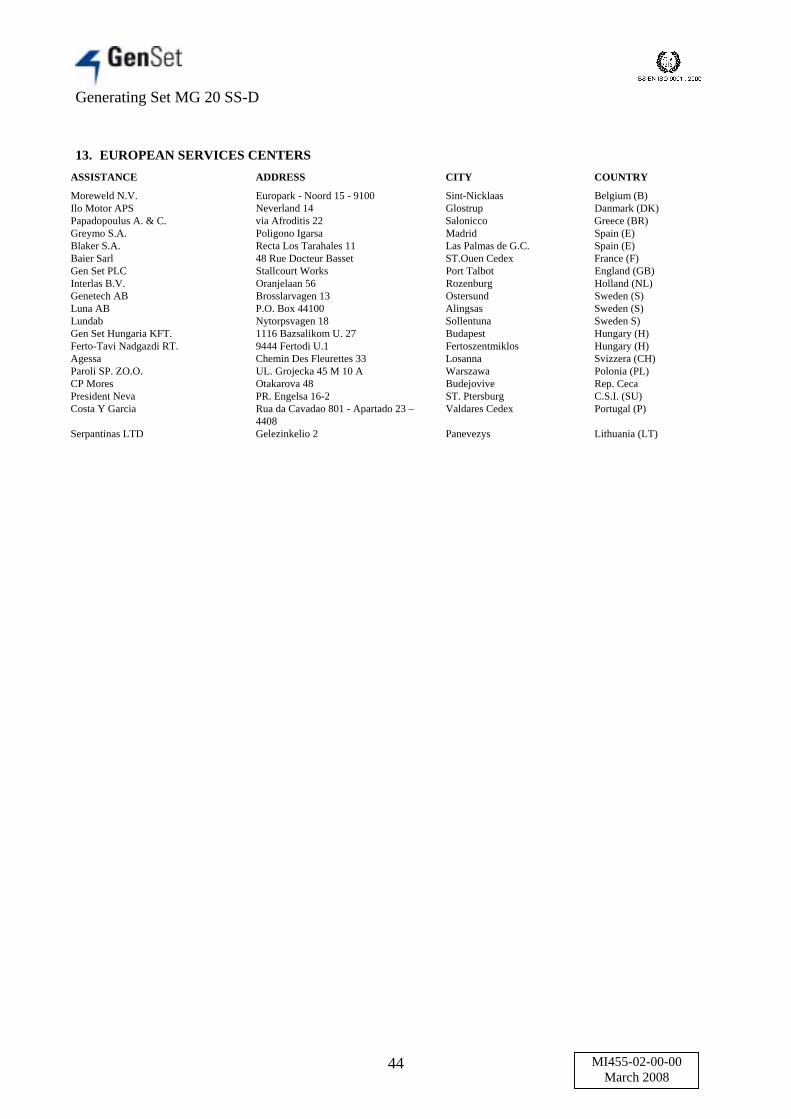
13. EUROPEAN SERVICES CENTERSASSISTANCE ADDRESS CITY COUNTRY
Moreweld N.V. Europark - Noord 15 - 9100 Sint-Nicklaas Belgium (B)Ilo Motor APS Neverland 14 Glostrup Danmark (DK)Papadopoulus A. & C. via Afroditis 22 Salonicco Greece (BR)Greymo S.A. Poligono Igarsa Madrid Spain (E)Blaker S.A. Recta Los Tarahales 11 Las Palmas de G.C. Spain (E)Baier Sarl 48 Rue Docteur Basset ST.Ouen Cedex France (F)Gen Set PLC Stallcourt Works Port Talbot England (GB)Interlas B.V. Oranjelaan 56 Rozenburg Holland (NL)Genetech AB Brosslarvagen 13 Ostersund Sweden (S)Luna AB P.O. Box 44100 Alingsas Sweden (S)Lundab Nytorpsvagen 18 Sollentuna Sweden S)Gen Set Hungaria KFT. 1116 Bazsalikom U. 27 Budapest Hungary (H)Ferto-Tavi Nadgazdi RT. 9444 Fertodi U.1 Fertoszentmiklos Hungary (H)Agessa Chemin Des Fleurettes 33 Losanna Svizzera (CH)Paroli SP. ZO.O. UL. Grojecka 45 M 10 A Warszawa Polonia (PL)CP Mores Otakarova 48 Budejovive Rep. CecaPresident Neva PR. Engelsa 16-2 ST. Ptersburg C.S.I. (SU)Costa Y Garcia Rua da Cavadao 801 - Apartado 23 –
4408Valdares Cedex Portugal (P)
Serpantinas LTD Gelezinkelio 2 Panevezys Lithuania (LT)

Generating Set MG 20 SS-D
45 MI455-02-00-00March 2008
14. WARRANTY
GEN SET warrants its products, provided they have not been modified, for a period of 12 months from the date of handing over to the End User. Withinthese terms, in all the countries where a service organization is in place GEN SET commits itself to replace or repair the defective parts resulting fromfaulty material, workmanship and/or assembly through its authorized service stations.The choice whether to replace or repair the defective parts is exclusively reserved to GEN SET and/or its authorized service stations.The warranty in the rest of the world is limited to the supply ex-works free or charge of those parts which will result unsuitable for reuse due to originaldefects.The warranty will apply after a check of the defective parts from the factory.The warranty will apply after a check of the defective parts from che factory.The travel, board and lodging expenses of the personnel who will perform the repairs are at the charge of the End User as are the packing andtransportation costs both for the defective and the replaced parts.In no case the client can claim the cancellation of the contact or a damage compensation due to the use or the impossibility to use the equipment bothtotally or partially.The present warranty does not apply to starting batteries, diesel and gasoline engines mounted on gen set machines for which the respectivemanufactures will intervene directly.The warranty will automatically expire: if the customer has not fulfilled the contractual payment obligations. when the factory seals have been broken. when dismantling, repair or modifications have been executed by unauthorized personnel not being part of the GEN SET service organization. when the equipment has been subject to negligent or improper use.
The present warranty does not apply to wear and tear parts.COMING IN FORCE OF THE WARRANTY RIGHTSEach GEN SET machine is delivered with a warranty certificate which must be filled out in each part and be validated by the stamp and signature of thedealer.
Cut out and send to: GEN SET S.p.A. - Servizio Assistenza Viastazione, 5 - 27030 Villanova D’Ardenghi (Pavia)The guarantee certificate must be kept and shows before any request of intervention.
15. ENGINE WARRANTY AND SPARE PARTS
15.1 INTRODUCTION
Please follow carefully the engine operation manual, in order to obtain a safe use of the machine.
15.2 ENGINE WARRANTY
On purchase, please fill in the engine warranty certificate and mail it to the engine manufacturer.
15.3 SPARE PARTS
Spare parts have to be ordered as follows:For the engine: Please contact assistance service giving the reference codes that you find on the engine SPARE PARTS USE AND MAINTENANCEmanual.For the generator and relevant equipment: Please contact directly GEN SET, giving the serial n°. of the machine and the reference codes that youfind on the SPARE PARTS.
Generating Set MG 20 SS-D
46 MI455-02-00-00March 2008
TABLE OF CONTENTS
1. TECHNICAL SPECIFICATIONS............................................................................................ 21.1 GENERATOR ......................................................................................................................... 21.2 ENGINE................................................................................................................................... 21.3 GENERAL FEATURES.......................................................................................................... 2
2. CONTROLS DESCRIPTION.................................................................................................... 32.1 FRONT PANEL....................................................................................................................... 32.2 REMOTE CONTROL PANEL ............................................................................................... 52.3 PANNELLO LATERALE / SIDE PANEL ............................................................................. 6
3. RICAMBI / PARTS LIST .......................................................................................................... 74. WIRING DIAGRAM ................................................................................................................ 225. CONTROL DEVICES MOUNTED ABOARD...................................................................... 26
5.1 MP24 CONTROL UNIT FOR GENERATING SET............................................................ 265.1.1 CONTROL UNIT PUSH-BUTTON AND LED FUNCTIONS................................... 265.1.2 DAS, AUTOMATIC ENGINE SHUT OFF .................................................................. 275.1.3 PARAMETERS DESCRIPTION .................................................................................. 29
5.2 RD2 EARTH LEAKAGE CIRCUIT BREAKER ................................................................. 335.3 EMERGENCY STOP BUTTON........................................................................................... 345.4 OPEN DOOR......................................................................................................................... 345.5 BATTERY ISOLATOR SWITCH ........................................................................................ 34
6. EARTHING THE POWER GENERATOR........................................................................... 357. STARTING THE MACHINE.................................................................................................. 36
7.1 PROCEDURE FOR MANUAL STARTING (WITHOUT REMOTE CONTROL.............. 368. USING THE REMOTE CONTROL IN MANUAL MODE ................................................. 389. USING THE REMOTE CONTROL IN TIMER MODE...................................................... 39
9.1 TIMER SETTING.................................................................................................................. 3910. STOP PROCEDURES .............................................................................................................. 40
10.1 PROCEDURE FOR MANUAL SWITCHING OFF......................................................... 4010.2 PROCEDURE FOR REMOTE CONTROL SWITCHING OFF ...................................... 40
11. GENERAL USE INSTRUCTIONS ......................................................................................... 4111.1 TRANSPORTATION........................................................................................................ 4111.2 CAUTION.......................................................................................................................... 4111.3 RUNNING IN.................................................................................................................... 4111.4 STARTING AND WORKING.......................................................................................... 4111.5 FORBIDDEN USE ............................................................................................................ 4111.6 SERVICE AND CLEANING............................................................................................ 4111.7 ADJUSTMENT AND REGULATIONS........................................................................... 4111.8 TEMPORARY STANDSTILL.......................................................................................... 4211.9 SCRAPPING...................................................................................................................... 42
12. SYMBOLS ................................................................................................................................. 4313. EUROPEAN SERVICES CENTERS...................................................................................... 4414. WARRANTY ............................................................................................................................. 4515. ENGINE WARRANTY AND SPARE PARTS ...................................................................... 45
15.1 INTRODUCTION ............................................................................................................. 4515.2 ENGINE WARRANTY..................................................................................................... 4515.3 SPARE PARTS.................................................................................................................. 45