generating unit m7 - ibiblio
TRANSCRIPT
WAR DEPARTMENT TECHNICAL MANUAL
Generating Unit M7
WAR DEPAR TMENT TECHNICAL MANUAL
TM ,9-618
Generating Unit M7
This Manual supersedes paragraph 84 of TM 9-370, 90-mmAntiaircraft gun materiel MI and MIA1, 31 December 1942.
WAR DEPARTMENT
30 JULY 1943
WAR DEPARTMENT
WASHINGTON 25, D.C., 30 July 1943
TM 9-618, Generating Unit M7, is published for the information andguidance of all concerned.
EA.G. 300.7 (30 Jul 43)0.0. 461/49023 Rar. Ars. (30 Oct 43)J
BY ORDER OF THE SECRETARY OF WAR:G. C. MARSHALL,
Chief of Staff.
OFFICIAL:
J. A. ULIO,Major General,
The Adjutant General.
.-<DLSTRIBUTION: R 9(4); Bn and H 44(3); Bn 9(2); C 9(8); IC-c 44(5).
5 E- ~ (For eplanation of symbols, see FM 21-6.)

-AN .' , *TM 9-618
CONTENTS
Paragraphs PagesPART ONE-OPERATING INSTRUCTIONS
SECTION I. Introduction .............. 1- 4 2- 10
II. Operation and controls ...... 5- 10 11- 20
III. Inspection ................. 11- 16 20- 24
IV. Lubrication ............... 17- 20 24- 29
V. Tools and equipment ........ 21- 24 29- 31
VI. Operation under unusual condi-tions .................. 25- 36 31- 40
PART TWO-ORGANIZATIONAL MAINTENANCEINSTRUCTIONS
SECTION VII. Maintenance allocation ..... 37- 38 41- 43
VIII. Frame ................... 39- 41 44
IX. Engine .................. 42- 45 44- 52
X. Cooling system ............ 46- 53 53- 65
XI. Exhaust system ............ 54- 59 65- 72
XII. Fuel system .............. 60- 67 73- 85
XIII. Engine lubrication system .... 68- 72 85- 93
XIV. Engine electrical system ..... 73- 80 94-114
XV. Generating system ......... 81- 90 114-124
XVI. Instrument panel and instru-ments ................. 91-114 125-141
XVII. Painting ................. 115-120 141-143
XVIII. Storage and shipment ....... 121-123 144-147
XIX. References ............... 124-125 148-149
INDEX ................................ 150-155
This manual supersedes paragraph 84 in TM 9-370, dated 31 December 1942.

TM 9-6181-2
GENERATING UNIT M7
PART ONE-OPERATING INSTRUCTIONS
Section I
INTRODUCTION
Paragraph
Scope ................... ............... ......... 1
Characteristics . ................ .......... 2Differences among models ............................ 3Data ............................................. 4
1. SCOPE.a. This manual is published for the information of the using arms
and services.
h. In addition to a description of the Generating Unit V[17, thismanual contains technical information required for the identification,use, and care of the materiel.
c. Disassembly, assembly, and such repairs as may be handled byusing arm personnel may be undertaken only under the supervision ofan officer or the chief mechanic.
d. In all cases, where the nature of the repair, modification, or ad-justment is beyond the scope or facilities of the unit, the responsibleordnance service should be informed so that trained personnel withsuitable tools and equipment may be provided, or proper instructionsissued.
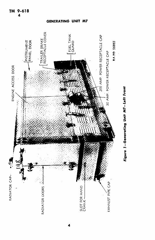
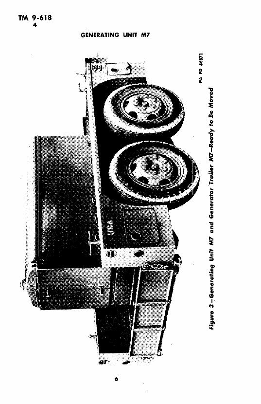
2. CHARACTERISTICS.a. The Generating Unit M7 (figs. 1, 2, and 3) is a gasoline engine
actuated generator mounted on a specially designed rubber-tiredtrailer or on wood skids. The frame is of welded structural steel con-struction. It is bolted to the floor of the trailer. The engine and gener-ator assembly is enclosed by a sheet metal canopy bolted to a baseframe. Side doors give access to the instrument panel, engine, gener-ator, and other parts within the canopy (figs. 4 and 5).
h. A 10-gage, sheet-steel instrument and control panel is locateuover the generator on the left-hand side of the unit.
e. The Generator Trailer M7, illustrated in figures 3 arid 4, isdesigned primarily for travel on highways, and to,afford a solid operat-ing foundation for the generating unit. Four built-in corner lift jacks
2

TM 9-6182-4
INTRODUCTION
(fig. 4) give firm ground contact, and lift the weight off springs andtires. The trailer can be coupled to any vehicle equipped with a pintlehook. Brakes and lights operate electrically from any vehicle havinga suitable outlet and controller. A retractable parking wheel supportsthe drawbar when the trailer is uncoupled. For generator trailer operat-ing instructions, see TM 9-881.
d. Some Generating Units M7 are mounted on Generator Skids M1instead of on the trailer. The skids are 3-inch by 6-inch oak runners,bolted to the under side of the generator platform. They facilitatehandling of the unit in loading and unloading from the truck on whichit is carried.
3. DIFFERENCES AMONG MODELS.
a. Generating Units M7 have been produced by five manufacturers,namely: International Diesel Electric Co., Cummings Diesel EngineCo., Hobart Bros., U. S. Motors Co., and Detroit Wax Paper Co. Thename of the manufacturer of a unit will be found on plates attachedto the instrument panel and to the rear panel of the canopy. Initialsor name appears on radiators except for Cummings Diesel Engine Co.units, which have blank radiators. Information and instructions givenin this manual cover all M7 Units. Whenever major differences in unitsof certain manufacture occur, or changes in procedure are necessary,supplementary information or instructions are given, identified by theinitials of the manufacturer. There are no primary differences inmanufacture which would affect troop use or care, with the exceptionof the Hobart unit, which has the generator exciter mounted on thesame shaft, and within the same housing as the generator rotor.
h. Generating Unit M7A1. The designation Generating UnitM7A1 has been assigned to all Generating Units M7 which have beenmodified by the addition of a voltage regulator to the unit. Thevoltage regulator is designed to hold the voltage variation to within±2 percent from full load to no load operation.
4. DATA.
Length, over-all .................................... 100/2 in.
Width, over-all . ................................... 407/8 in.
Height, over-all ................................... 563/4 in.
Weight, less fuel and water .......................... 4,297 lb
Fuel capacity ........... ................ ...... .26 gal
Cooling system capacity ............................... 36 qt
Crankcase capacity ................................. 7 qt
Rated generator output.... .... 35-kva, 28-kw, 3-phase, 60-cycle, 125-v
3
TM 9-6184
GENERATING UNIT M7
> z <
, 0, 6, ~d w~ U 'E0u u
_ UJ -Cl
-0 -:~ C0 0u
< o
4r,/ <
F o

TM 9.6184
INTRODUCTION
u < F-
I !o <0
D
L_
i.
Z v
u..O
TM 9-6184
GENERATING UNIT M7
,~~~~~
3 %m
4
0S,
U
0
.5SS
a
3 _
a,
31 .6^ _ ..ortS:: f S C L
_t \|: f S(it:f:: L, :3|:: _ i _ < t
0 i Q 3 e l_
g 1i I Z -r
, a ti Sg }., >fM | r-a w 0N i S~~o
_ | L~~~a' an~~~s W) X~aw 11/ _ . 3 _ > e : .w S ' . L\R a _ _ _ E IO
B.~~~~~~~~~~~~~~~~~~~~~~~~~~~~~~ 61nI1 * iff ^ K @~~~~~~~c
, __ C _ ..................... 3,,: 'a r
:j 1 3a [FJ 8~~~~~~.S \' -f ~~~~
: ' _ e _:j^

TM 9-6184
INTRODUCTION
uIe oGo aE
00
I'z
of
i Ll
-i
aX
< G il; If~~
3 4 ~~~i

TM 9-6184
GENERATING UNIT M7
Ico
tff:.. 0 COZ ~ ~,DLr%x z 1Iw ,,
),,
I I
u 1 1
H ~ : :

TM 9-6184
INTRODUCTION
z
~0 ~~~~a-. i o,- Wu -I
z z
2
I
z=~~ .. t z s i
0 L HH < m
o Uuo< HU
9
U~--<'UL

TM 9-6184
GENERATING UNIT M7
o0
9 o < nZ U
- oz
..I I
Ug U * UI,
I
I-
IL
10ma\
ld
Q ~~~~~~~~~~~L~~7

TM 9-6185
Section II
OPERATION AND CONTROLS
Paragraph
Preparing for first operation of generating unit ............ 5Engine and generator controls ......................... 6Starting the unit.....................7. .............. 7Operating the unit .................................... 8Stopping the unit ................................... 9General care and precautions .......................... 10
5. PREPARING FOR FIRST OPERATION OF GENERATINGUNIT.
a. Battery.(1) The battery is shipped dry, with the plates in a charged con-
dition. Vent plugs are screw-tight with sealing disks, and must remainso until the cells are filled with electrolyte. Store in a cool dry place,away from direct sunlight, radiation, or heating devices.
(2) Before using, the battery must be filled with electrolyte, andgiven a freshening charge by ordnance personnel.
b. Lubricating Oil.(1) Fill the engine crankcase oil pan (through the filler pipe) to
the proper level, as indicated by the "4/4" or "FULL" mark on thebayonet-type level gage (fig. 17). Since allowance must be made forthe oil filter capacity, it will be necessary to run the engine a fewminutes, recheck the level, and add oil to the "4/4" or "FULL" mark.
(2) Use the grade of engine oil specified in Lubrication Guide (fig.13), or for temperatures below zero degree F, in paragraph 27.
c. Cooling Water.(1) Fill the radiator with 36 quarts of clear water, using the softest
available. Be sure the radiator drain cock is closed.(2) For operation below 32 degrees F, the following mixture should
be added to the radiator: To 10 parts by volume of water, add thefollowing parts by volume of COMPOUND, antifreeze, after drainingoff an appropriate quantity of water:Temperature Water COMPOUND, antifreeze(degrees F) (parts by volume) (parts by volume)
+20 10 2+10 10 3Y/
0 10 5-15 10 71/4-30 10 10-40 10 12
11

TM 9-6185
GENERATING UNIT M7
° I Z ·Ln Iw II- 0 _ I'7 l
L m< 7 Z * m17W I U i~
<LDZ LC aLUJ
< < < H Z0
z ,I 8 0i I Tz: : ,
_ i~< 02 ,, 8 < _LLJ~U ~ w C0 <-,E N O w , -
uil 6 3 & PIL' g4-oRl I* _s, E
N l R ^ t!~ o U B tu Y- Z"C 1 ,

TM 9-6185-6
OPERATION AND CONTROLS
NOTE: Immediately start the engine, and run at idling speed withoutload until warm, to mix thoroughly the antifreeze and water solution.
d. Fuel. Fill the fuel tank with 26 gallons of gasoline. Fuel con-sumption (72 octane fuel) will be at the rate of approximately 1 gallonper 6 kilowatt hours at rated load of 28 kilowatts. When using 80octane fuel, the output of the generating unit is approximately 10 per-cent higher than when using 72 octane fuel.
6. ENGINE AND GENERATOR CONTROLS (fig. 8).a. Choke. The use of the choke, located at lower right in the
control group on the left-hand side of the instrument panel, dependsmainly on the climate in which the unit is operating. In cold climates,it should be pulled all the way out, and kept in this position for the firstfew revolutions of the engine crankshaft. In warm climates, this isseldom necessary. The choke should always be used as sparingly aspossible.
b. Throttle. The throttle is at the lower left in the controlgroup on the left-hand side of the instrument panel. Its use is normallyconfined to the starting and stopping of the engine. The engine isstarted with the throttle all the way in. As soon as the engine begins tofire, the throttle is pulled out quickly, until the speed indicated on thetachometer is approximately 600 rpm. As the engine warms up suffi-ciently for full speed operation, the throttle is gradually pushed in.When stopping the engine, the throttle is pulled to full out position, andthe engine allowed to idle for a minute before the ignition is turned off,otherwise, backfire might damage muffler.
c. Doors. While the unit is running, both radiator doors areusually fastened open. For quick warming up in cold weather, thedoors maybe kept closed until the desired engine temperature isobtained. While the unit is running, the instrument panel door is open,and fastened back, with the chain provided, or with door props duringrainy weather. Other canopy doors are kept closed, unless their use isrequired to help adjust the temperature.
d. Field Rheostat. The field rheostat, located on the lower leftcenter of the instrument panel, controls the output voltage of the gen-erating unit. Turning the knob counterclockwise increases the voltagedelivered.
e. Ignition Switch. The ignition switch, which controls the 6-voltstarting and ignition system, is at the upper left in the control group onthe left side of the instrument panel.
f. Starter Switch. The starter, or cranking switch, is on'the leftside of the instrument panel, just below the throttle and choke controls.
g. Meter Switch. The meter switch used to check amperage andvoltage is at upper center of the instrument panel.
13
TM 9-6186
GENERATING UNIT M7
'f: A
RA PD 56875Figure 9-Hand Cranking Engine
h. Voltmeter. The voltmeter is centrally located on the instru-ment panel, at the left of the meter switch. This instrument indicatesthe voltage of the current generated, normally 125 volts.
i. Am~neter. The ammeter is centrally located on the instrumentpanel, to the right of the meter switch. This ammeter, in conjunctionwith the meter switch, indicates the amperage of current beiing deliv-ered.
j. Load Switch. The switch, which starts and stops the delivery14

TM 9-6186
OPERATION AND CONTROLS
RA PD 56876
Figure 10--Crank in Holding Clips Against Left Side Panel
of power to the load, is on the right-hand side of the instrument panel,directly below the unit name plate.
k. Tachometer. The tachometer, which is just below the left-hand light on the instrument panel, indicates the number of revolutionsper minute. Also on the tachometer is an odometer dial, which recordsthe total number of revolutions.
1. Temperature Gage. The engine temperature gage is at thelower left-hand side of the instrument panel. The engine running tem-perature should be between 160 degrees F, and 180 degrees F.
m. Oil Pressure Gage. The oil pressure gage is at the extremeleft center of the instrument panel. The pressure should be approxi-mately 25 pounds at 1,200 rpm.
n. Battery-charging Ammeter. The battery-charging ammeteris located in the upper left-hand corner of the instrument panel.
o. Fuel Gage. A mechanical-type fuel gage set into the tank isused on International Diesel Electric Company, Cummings DieselEngine Company, and Hobart units. Units manufactured by U. S.Motors Company have an electric fuel gage mounted on the instru-ment panel.
pe mnue.Alo n hetahoetrisanomerdilwhcrcrs

TM 9-6186-7
GENERATING UNIT M7
Figure !I--Voltmeter and Meter Switch- Showing CorrectExciter Indication
p. Lamp-dimming Rheostat. The lamp-dimming rheostat, usedto dim the 125-volt lamps, is located at the top center of the pan~el.
q. Frequency Meter. Some generating units employ a vibratingreed type frequency meter in place of a tachometer to determineengine speed and a-c frequency output. Normal engine speed (1,200-rpm) and a-c frequency output (60 cycles) are indicated whten thereed over the 60-line on the instrument reaches its maximum vibra-tion, with adjacent reeds vibrating less vigorously.
7. STARTING THE UNIT.
a. First Starting. For starting the unit for the first tinne, seeparagraphs 5 and 12, then proceed as outlined below.
b. Preliminary Instructions.(1) Make sure that the load switch handle is in the "OFF" position.(2) See that the fuel valve (located next to the gas tank in the fuel
line) is open.(3) Remove exhaust pipe cap, and connect exhaust tube.(4) Remove power receptacle cap, and connect plug (fig. 1).
16

TM 9-6187
OPERATION AND CONTROLS
c. Warming Up.(1) Pull out the choke, if necessary.(2) See that the throttle is pushed in all the way.(3) Start the engine by placing the ignition switch in the "ON"
position, and pressing the starter switch until the engine fires. If start-ing after all previous fuel has been drained or consumed, a longerperiod of time will be required before fuel reaches the carburetor andthe engine fires. NOTE: On occasion, it will be found that oil has beenadded to the top of each cylinder of the power plant prior to shipment,to prevent rusting. When starting for the first time, a unit which hasbeen treated in this manner, smoking will most likely result until thisoil is burned out.
(4) When the engine fires, pull out the throttle quickly until thetachometer indicates about 600 rpm. Keep the engine at that speeduntil it is sufficiently warmed up for full speed operation, then gradu-ally push in the throttle.
hand crank, be sure both the load and ignition switches are in the"OFF"'position. Pull choke all the way out, then give the hand cranktwo complete turns. Readjust choke so that it id one-third out, and
17
TM 9-6187-8
GENERATING UNIT M7
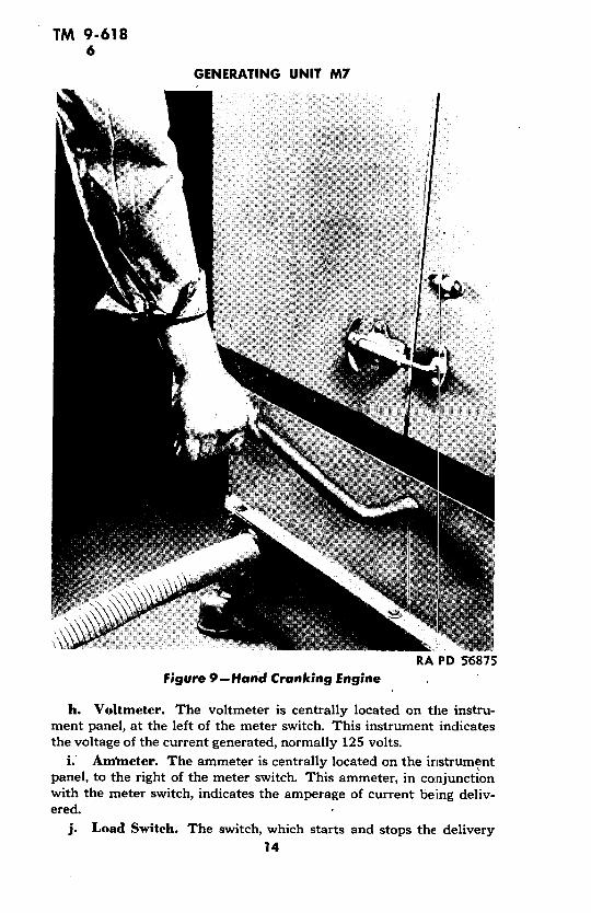
turn ignition "ON." Give hand crank (fig. 10) a quick turn, by pullingup from the bottom (fig. 9).
8. OPERATING THE UNIT.a. Load Switch. The first step, to begin the delivery of current
from the generator to the load connected to the power outlets, is topull the load switch handle (at extreme right on the instrument panel)to the "ON" position.
1h. Voltage Control. To provide the requisite voltage for thepower receptacle line (normally 125), slowly rotate the field rheostatcontrol handle counterclockwise until the voltmeter indicates 125.
c. Load Meter. To check the voltage of the exciter, the amperageof the current being delivered to each of the three phases of the con-nected load, and the voltage between phases, the meter switch is pro-vided. The four positions of the control knob, "EXC," "A," 'B," and"C," are labeled on the face plate of the switch. When the indicatingmark on the control knob is turned to "EXC," the exciter voltage isreflected on the voltmeter (fig. 11). As the switch turns to the "A,""B," and "C" phases of the circuit, the amperage and voltage show onthe ammeter and voltmeter (fig. 12). The average of the three read-ings on the ammeter should not exceed 162 amperes for continuousoperation, or 202 amperes over a period of operation not to exceed 2hours. The difference in ammeter readings should not exceed 10 per-cent of the average. If the load is largely of the resistance type, suchas lighting or heating units, so that the power factor is higher than 80percent, the current must be limited to approximately 129 amperesnormal load, and 162 amperes overload, in order not to exceed theengine's rated capacity.
d. Panel Illumination.(1) Two 125-volt bulbs are located in rubber sockets at the top of
the panel. The light switch is at the right of the center of the panel,and the lamp-dimming rheostat is located between the lights. In fieldservice, the illumination should be kept at as low a level as possible.
(2) As the 125-volt current is available only when the unit is oper-ating, an auxiliary 6-volt light is provided at the top of the panel.A snap switch to control this is immediately above the choke handle.
e. Trouble Lights.(1) The 125-volt trouble light, furnished with the unit and carried
in the tool box, may be plugged into the T-slot receptacle on the panelproper, or into one of the four receptacles in the apron below.
(2) The 6-volt trouble light (also in the tool box) has a receptacleprovided for it above the starter switch.
f. Power Tools. Power tools that may be used for repair ormaintenance work on the unit can be plugged into the T-slot recep-tacles in the panel apron.
18

TM 9-6188-10
OPERATION AND CONTROLS
g. Temperature Control. The running temperature of the engineshould be maintained at 160 degrees F to 180 degrees F. To maintaina correct temperature, the radiator doors, the engine side doors; andthe door behind the instrument panel can be opened or closed to suitclimatic conditions. All doors are provided with means for holdingthem in the "OPEN" position.
h. Battery-charging Ammeter. The battery-charging ammeterindicates in amperes the rate of charge or discharge of the 6-volt bat-tery. It is of the automotive type.
i. Tachometer. When the engine is running properly, the tach-ometer should indicate 1,200 rpm at full load, which will produce analternating current of 60 cycles per second as required by the load.At less than full load, the speed will be slightly higher. The speed isshown in hundreds of revolutions per minute.
9. STOPPING THE UNIT.a. Load Switch. First operation in stopping the unit is to dis-
connect the load by pulling the load switch handle down to the "OFF"position. When the unit is not in operation, this switch should alwaysbe off, thus avoiding the possibility of ever starting the engine withthe load on.
b. Rheostat. The field rheostat knob should be turned clock-wise as far as possible.
c. Throttle. The throttle is pulled out to bring the engine downto idling speed for the full minute of idling required before stopping.Otherwise, there is the chance of backfiring and muffler damage. Theproper idling speed is 350 to 400 rpm.
d. Ignition. Final operation of stopping is to snap the ignitionswitch to the "OFF" position.
10. GENERAL CARE AND PRECAUTIONS.a. The generating unit should be kept clean and adequately sup-
plied with gasoline at all times. Lubrication and servicing should be inaccordance with instructions set forth in sections IV and VI.
h. Exercise care to see that the main switch is always open, whenconnecting or disconnecting the power cable and, before starting theengine.
c. If the unit is used in any building or enclosure, be sure that ahose or pipe is attached to the exhaust pipe and run through an open-ing to the outside. Exhaust fumes and gases might prove harmful tothe operating personnel.
c examinations should be made to see that all electrical
TH;ARMY ELIBAY-WA 'INGTON, D.C.

TM 9-61810-11
GENERATING UNIT M7
connections and leads are in good order and that the electrical indica-tors and controls are functioning properly. When not in use, see thatthe receptacle cover is screwed on the outlet receptacle.
e. Do not pour gasoline into the fuel tank while the engine is run-ning, nor while the ignition switch is turned on.
f. Never permit the oil to fall below the "2./4" mark on the bayo-net gage. On the other hand, do not overfill the crankcase, as thismight raise the oil level to a point where the connecting rods woulddip in and throw oil on cylinder walls, causing smoke, oil pumping,excessive carbon deposits, and fouled spark plugs. Fill only to the"4/4" or "FULL" mark on the gage rod, except as indicated in sectionVI, for operation below zero degree F.
Section III
INSPECTION
Paragraph
Purpose ....... .................................. 11
Prestarting inspection ............................... 12
Inspection during operation .. ........... ......... 13
Inspection after short operation .... ................... 14
Inspection after long operation ...................... 15
Weekly and monthly inspections .................... 16
I 1. PURPOSE.a. Inspection of the generating unit is vital. Thorough sysl:ematic
inspection at regular intervals is the best insurance against an unex-pected breakdown at the critical moment when maximum perfor:manceis absolutely necessary. Never let the materiel run down. Keep it infirst class fighting condition by vigilant inspection and prompt main-tenance.
la. Inspection is for the purpose of determining the condition of themateriel, whether repairs or adjustments are required, and the reme-dies necessary to insure serviceability and proper functioning. Its im-mediate aim is trouble prevention, which includes:
(1) Preventive maintenance.(2) Discovering evidence of improper treatment of the materiel
before receipt.(3) Determining when replacement of parts is necessary because
of ordinary wear or accidents.
20
TM 9-61811.13
INSPECTION
c. The Chief of Ordnance should be advised (through the local ord-nance officer) of any chronic troubles, technical failures, or unsatisfac-tory operation of any parts or units. Any suggestions for the improve-ment of the inspection procedure or handling technique (based onactual operating experience) should likewise be forwarded so that allunits may benefit.
12. PRESTARTING INSPECTION.
a. Check fuel supply, engine oil, water, or antifreeze solution inradiator, lubrication, and specific gravity of battery electrolyte. Inspectglass sediment cup on fuel pump; empty, if water is present.
h. Examine, engine and trailer floor for leaks from radiator, fueltank, water, fuel, or oil lines. Examine all lines for leaks.
e. Check unit for loose parts and loose electrical connections.
d. Check fuses and instrument panel lights.
e. Inspect all brushes, slip rings, and commutators for necessaryservicing or replacement.
f. Check tension on exciter and radiator fan belts.
g. Examine mounting and other important bolts, and tighten, ifnecessary.
h. Check tools, spare parts, and fire extinguisher.
i. See that the radiator core is clear.
j. See that the exhaust hose is in place.
k. Make sure the load switch is "OFF."
I. Make sure field rheostat is turned as far as possible in clockwisedirection.
13. INSPECTION DURING OPERATION.
a. Constant Attention. While the unit is running, the operatorshould be constantly alert to detect abnormal functioning. He shouldbe trained to detect unusual engine noises. He should quickly be con-scious of overheating or of the smell of burning insulation.
b. Instruments. All instruments should be inspected at regularintervals during operation. Special attention should be given to theamperage developed. Check the three phases of the circuit as describedin paragraph 8 c. The battery-charging ammeter will not always indi-cate charging. If the battery is fully charged, the charging generatorwill not operate. Just after starting, however, the ammeter should indi-cate charging.
21

TM 9-61814-16
GENERATING UNIT M7
14. INSPECTION AFTER SHORT OPERATION.a. General. The inspection after' a short period of operation
should roughly duplicate the prestarting inspection, with the additionof a check of running parts.
h. Leaks, etc. Examine fuel, water, and oil lines for leaks. Fillthe fuel tank. 'If necessary, change the engine oil, or add oil to main-tain the correct level (fig. 13). Add water or antifreeze solution toradiator, if required.
c. Running Parts. Check all running parts for evidence of over-heating. Examine electric wiring for breaks or loose connections. Thebest check on running parts is made after a short period of operation.Insert the hand crank for hand starting. Running parts are functioningfreely if the crank can be turned without too much effort.
d. Nuts and Bolts. Check tightness of bolts and nuts.
15. INSPECTION AFTER LONG OPERATION.a. General. After each lengthy period of operation, an exhaustive
check should be made for any actual or incipient failure of parts orequipment. Replacements made from the spare parts supply should belisted for renewal.
h. Lines. All tubing and pipe lines must be examined for leaks.Joints and fittings must be tested for tightness., Gaskets must bechecked, and replaced where necessary.
c. Electrical. Electrical equipment, including all switches andinstruments, must be subjected to a thorough examination and test.
d. Clearances. Spark plug, distributor point, and valve tappetclearances must be checked.
e. Lubrication. Special attention must be given to the lubricatingsystem. See sections IV and XIII.
f. Tools and Fire Extinguisher. Tools are checked against thetool list, and missing tools reported. The fire extinguisher must beexamined, and the piston head leather given 1 or 2 drops of OIL,engine, SAE 10. Refill, if necessary.
g. Check battery electrolyte.
h. Examine belts for wear, or for the necessity of adjustment.i. Check light bulbs and fuses.
j. Examine muffler for cracks.
16. WEEKLY AND MONTHLY INSPECTIONS.a. Inspections at stated intervals, regardless of the amount cf actual
service the unit has given during the period, are valuable because theywill bring to light not only operational mechanical failures, but alsotroubles due to deterioration which can occur even when the unit hasnot been in operation.
22

TM 9-61816
INSPECTION
Il. Weekly inspections will at least duplicate the inspection afterlong operation. In these weekly inspections, the possible effects ofunusual climatic conditions or conditions of terrain should be takeninto consideration and checked as detailed in section VI.
c. Monthly inspections should be the most exhaustive possible.Check list is given below:
(1) FRAME AND CANOPY. Examine connecting nuts and bolts fortightness.
(2) ENGINE.'(a) Check crankcase, block, head, and head gasket for cracks or
leaks. See that all bolts are tight.(b) Remove valve covers and examine valve rods, springs, and
valve clearances. Renew cover gaskets, if necessary.(c) Run engine, and listen for piston slap, bearing knock, or carbon
knock.(d) Check oil pressure. If below normal, it may indicate loose
engine bearings.
(3) COOLING SYSTEM.
(a) Examine radiator and connections for signs of leakage, clog-ging, or damage.
(b) Inspect fan and supporting bracket.(c) Check belt for proper tension, for cracks, or for oil soaking.(d) Examine water pump for cracks and leaks. Make sure the shaft
rotates freely.
(4) EXHAUST SYSTEM.
(a) Examine manifold for cracks.(b) Check manifold gaskets for leaks.(c) Examine muffler and exhaust pipe for cracks.
(5) FUEL SYSTEM.
(a) Inspect fuel pump, fuel pump mounting, and connections.Empty the sediment cup, and clean the fuel filter.
(b) Examine carburetor for tightness of screws, and for worngaskets.
(c) Inspect air cleaner. Clean element, and change oil.(d) Check choke and throttle action, and examine linkage.(e) Inspect fuel tank and fuel lines for signs of leaks.
(6) LUBRICATING OIL SYSTEM.
(a) Check oil pressure.(b) Check all oil lines and connections to governor and to oil pres-
sure gage.(c) Clean oil strainer.
(7) ENGINE ELECTRICAL SYSTEM.
(a) Inspect all wires and terminals for damage, wear, and looseness.
23
TM 9-61816-17
GENERATING UNIT M7
(b) Examine and test starter and switches.(c) Test battery, and check battery electrolyte.(d) Inspect distributor. Remove cap and examine for cracks.
Inspect breaker points, spring, rotor, and cap inserts for signs of pittingand burning. Check cam for evidence of wear.
(e) Test the action of the starting motor. Inspect commutator andbrushes for dirt or signs of wear.
(f) Check battery-charging generator action for excessive arcing atthe brushes. Examine for sticking or worn brushes, and burned com-mutator bars.
(8) GENERATING SYSTEM.
(a) Check amperage and voltage of current delivered. Inspect alter-nator brushes for signs of wear, proper spring pressure, and freedomof action in holders. Examine brush holders to see if they are clean.
(b) Check exciter brushes for signs of wear, proper spring pressure,and freedom of action in holders. Inspect condition of brush holders,brush holder rod insulating washers, and pigtail connections. Checkcommutator for roughness or low, loose, or high bars.
(c) Check belt tension.(9) INSTRUMENT PANEL.
(a) Check tightness-of mounting bolts.(b) Inspect for loose wires or connections.(c) Check all fuses.
Section IV
LUBRICATION
Paragraph
Introduction .. ........ 1...............7....... 17Lubrication guide .. ...... ......... 18
Points to be s 'i viced and,'or lubricated by ordnance main':e-nance personnel .............. ... ..... .. ...... 19
Reports and records .............. ........ ........ 20
17. INTRODUCTION.
a. Lubrication is an essential part of preventive ma:intenance,determining to a great extent the serviceability of parts and assemblies.Materiel must be lubricated in accordance with the latest instructionscontained in Technical Manuals and Ordnance Field Service Bulle-tins. Lubricating fittings are identified by a red circle 3/4 inch indiameter.
24

TM 9-61818
LUBRICATION
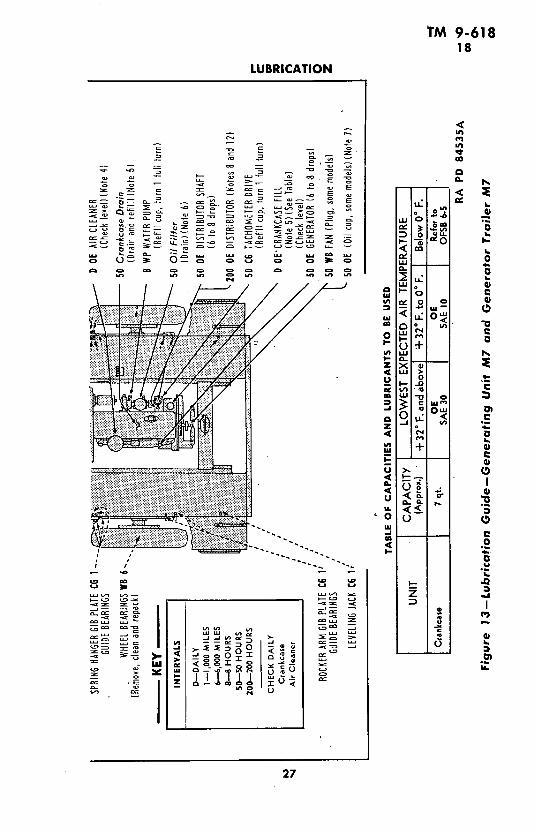
18. LUBRICATION GUIDE.a. General. Lubrication instructions for this materiel are con-
solidated in a Lubrication Guide (fig. 13). These specify the pointsto be lubricated, the periods of lubrication, and the lubricant to beused. NOTE: The Lubrication Guide and notes set forth below coverboth the Generating Unit M7 and Generator Trailer M7. They agreewith the Lubrication Guide packed with the materiel, which at thepresent time covers both of these items in one guide. TM 9-881 is theOperators Manual for the Generator Trailer M7.
b. Notes. The following notes apply to the Lubrication Guide·(fig. 13). Any note reference in the Lubrication Guide itself is to thesubparagraph below having the corresponding number. For lubrica-tion and service below zero degree F, refer to section VI.
(1) FITTINGS. Clean before applying lubricant. Lubricate untilnew lubricant is forced from the bearing, unless otherwise specified.CAUTION: Lubricate trailer points after washing.
(2) INTERVALS. Those indicated are for normal service. Forextreme conditions of speed, heat, water, sand, mud, snow, rough roads,dust, etc., reduce interval on guide by one-third or one-half or more,if conditions warrant.
(3) CLEANING. SOLVENT, dry-cleaning, or OIL, fuel, Diesel, willbe used to clean or wash all parts. Use of gasoline for this purpose isprohibited. All parts will be thoroughly dry before relubrication.
(4) AIR CLEANER. Daily, check level, and refill oil reservoir to beadlevel with used crankcase oil or OIL, engine, SAE 30 above +32 de-grees F, and SAE 10 from +32 degrees F to zero degree F. Belowzero degree F, remove oil, and operate dry. Every 150 hours or daily,if operating in extreme dust conditions. remove entire assembly. Cleanentire air cleaner and air pipes. Proper maintenance of air cleaners isessential to prolonged engine life.
(5) CRANKCASE. Drain only when engine is hot. Every 50 hours,drain, and refill to "FULL"' mark on gage. Run engine a few minutes,and recheck oil level. CAUTION: Be sure pressure gage indicates oilis circulating.
(6) OIL FILTER. Before draining crankcase oil, remove plug onfilter which covers the oil reversing valve and, with the engine running,drain 2 quarts of oil. Stop engine and drain crankcase. After draining,remove filter shell, and scrape sludge from filter felts. Clean filter shell,and reassemble. Refill crankcase to "FULL" mark on gage. Run enginea few minutes, recheck level, and add oil to "FULL" mark.
(7) FAN. If grease lubricated, remove plug and insert fitting tolubricate fan bearings. Replace plug. If oil lubricated, use hand oiler.
(8) DISTRIBUTOR. Every 200 hours, wipe distributor breaker cam
25

TM 9.61818
GENERATING UNIT M7
o _
*Zsa P _ > XV
0.-- _ _<z
' . -- ' 0 - ' X
.o
=oo 0 _ 00.0
U u 0 .0 . ,,= i , C._
> t ou , ,a
*0 4- 3 c- 2
_ O t t 0 t to 2
26
TM 9-61818
LUBRICATION
c c~~~~~~~~~~~.4
In
-D~~ - ~ ~ o
_ 'O
-~ ~~~~ ~- a.
cO0 0 ~~~~~~~~~ 00Q
- ~ ~ ~ ~ ~ ~ ~ . a-.
0- o ~ ~o- -.
-d~~~)0
ri ~ ~ ~ ~ ~ ~ ~ ~ ~ ~~~~u6 L L J
0 ~~P~ > - 0 u
~~-- ~ L~., .LU 0 E
-"a
a-.
,'ze , _, - '-.cc m -, u O I:
_ea a~ C --L CI-.0 -n .
0~~~
· ,,,, o m C
(,; iU UY oo -~
o u J = cc -JY °
~~~27
Mo - -t O c
I- 0-.
4W>m
YI ~ ~ ~ ~ ~ ~ M- al a
z -4
:+
U1 Q~~~~~~)
B o r
0<0
0 ~ ~ ~~~
*u A -
4 coilOLa
27~0CO- -- C
'-0 C,OOLL a
cc ni,, ~~~~, -
~~..0~ D u~!I~~0 .. o
'-A,.~~ ~ ~ ~ (.4·o
27LD -o

TM 9-61818-20
GENERATING UNIT M7
lightly with GREASE, general purpose, No. 1 above +32 degrees For No. 0 below -t32 degrees F; and lubricate breaker arm pivot, wickunder rotor and governor weight pivots, and slots with :1 to 2 dropsof OIL, engine, SAE 30 above +32 degrees F, SAE 10 frcom +32degrees F to zero degree F and OIL, lubricating, preservative, light,below zero degree F.
(9) BRAKE CABLES. Every 6,000 miles, remove inner cables, clean,and coat lightly with GREASE, general purpose, No. 0. Do not fillhousings.
(10) WHEEL BEARINGS. Remove bearing cone assemblies fromhub, and wash spindle and inside of hub. Inspect bearing races, andreplace, if necessary. Wet the spindle and inside of hub and hub capwith wheel bearing grease to a maximum thickness of l ,; inch only toretard rust. Wash bearing cones and grease seals. Inspect and replace,if necessary. Lubricate bearings with wheel bearing grease with apacker or by hand, kneading lubricant into all spaces in the bearing.Use extreme care to protect bearings from dirt and immediately re-assemble and replace wheel. The lubricant in the bearings is stufficientto provide lubrication until the next service period. Any excess mightresult in leakage into the brake drum.
(11) OILCAN POINTS. Every 50 hours or 1,000 miles, lubricatecaster hanger bearing, water pump drive chain, hand brake ratchet,linkage, tail gate hinges, hood hinges, and latches with OIL, engine,SAE 30 above -+-32 degrees F, SAE 10 from +32 degrees F to zerodegree F and OIL, lubricating, preservative, light, below zero degree F.
(12) POINTS To BE SERVICED AND/OR LUBRICATED BY ORDNANCE
MAINTENANCE PERSONNEL. Generator and exciter shaft bearings,
starter, distributor (disassembly only) (par. 19).(13) POINTS REQUIRING No LUBRICATION SERVICE. Sprirlgs,.gov-
ernor, flexible coupling.
19. POINTS TO BE SERVICED AND/OR LUBRICATED BYORDNANCE MAINTENANCE PERSONNEL.
a. Generator and Exciter Shaft Bearings. Yearly, or wheneverthe generator and/,or exciter is disassembled, remove, clean, and re-pack the bearings with GREASE, lubricating, special.
b. Starter. Whenever starter is disassembled, clean and coatbearings and seats with OIL, engine, SAE 10.
e. Distributor. Whenever distributor is disassembled, packpockets in governor laminated weights with GREASE, general pur-pose, No. 1 above +32 degrees F and No. 0 below +32 degrees F.
20. REPORTS AND RECORDS.
a. Reports. If lubrication instructions are closely followed, properlubricants used, and satisfactory results are not obtained, a report will
28
TM 9-61820-22
TOOLS .,ND EQUIPMENT
be made to the ordnance officer responsible for the maintenance of themateriel.
l>. Records. A complete record of seasonal changes of lubricantswill be kept in the Artillery Gun Book for the materiel.
Section V
TOOLS AND EQUIPMENT
Paragraph
Introduction .... ............. ... 21
Tools .. ....... ..... ..... 22
Accessories .... ......... .... ............ ........ 23
Fire extinguisher ...... .. .. ............ 24
21. INTRODUCTION.a. The materiel described herein includes tools and equipment
for general care, maintenance, and preservation. Accessories shouldnot be used for purposes other than as prescribed and, when not inuse, should be stored in the places or receptacles provided.
22. TOOLS.a. Service Tools Supplied with the Generating Unit. These
tools are carried in the tool box:Chisel, coldFile, millHammer, ball peenPliers, combinationPunch, pinScrewdriver, 4-in. bladeScrewdriver, 6-in. bladeScrewdriver, offsetWrench, adjustable, 12-in.Wrench, and gage, distributorWrench and handle, spark plugWrench, double, open-end, 3/8 x 7/ ,; in.Wrench, double, open-end, 1/2 x ' in.Wrench, double, open-end, 5/8 x " ,; in.Wrench, double, open-end, 5/8 x 3/4 in.Wrench, double, open-end, 7/8 x 1, ,; in.Wrench, double, open-end, l1 q; x 1!/,; in.Wrench, double, open-end, 11/4 x 17/1 ~; in.Wrench, socket-head set screw, 1/8 in.Wrench, socket-head set screw, ._2 in.Wrench, tappet (2)
29

TM 9-61822
GENERATING UNIT M7
RA PD 56883
Figure 14-Fire Extinguisher Removal
N
, . ,<, P STON
BARREL
FILLER CAP
-, y,'#nlE t.,ANK
RA PD 56884
Figure 15-Fire Extinguisher in Use30

TM 9-61823-24
OPERATION UNDER UNUSUAL CONDITIONS
23. ACCESSORIES.Accessories Quantity Where Carried
Crank 1 Left side panelCup, oil drain 1 Floor of trailerFire extinguisher, 1-quart 1 On instrument panelLight, trouble, 6-volt 1 Tool boxLight, trouble, 125-volt 1 Tool boxOilcan, 3-inch spout 1 Tool boxPadlocks, for trailer 2 Tool box
24. FIRE EXTINGUISHER.a. Location. The fire extinguisher, filled with a CARBON TET-
RACHLORIDE solution, is located at the right of the instrumentpanel (fig. 14).
b. Operation. Lift latch on holding clip, and pull out pump.Hold plunger barrel in left hand, and let tank drop to right-angleposition. Operate handle with right hand, first unlocking by a turn ineither direction (fig. 15).
c. Refilling. Remove hexagonal filler cap, and fill to capacity.Replace cap.
d. Maintenance. At least once a year, the extinguisher should bepartially discharged, and refilled. At this time, the pump piston shouldbe removed, and the pump piston head inspected. If the leather is dry,apply and work in 1 or 2 drops of OIL, engine, SAE 10. To removepiston, take out round-head screw at top of barrel, and the piston canbe pulled out.
Section VI
OPERATION UNDER UNUSUAL CONDITIONSParagraph
Cold weather maintenance ............... ......... 25Gasoline for low temperatures ........................ 26Engine lubrication ... .................. ..... 27Protection of cooling system .......................... 28Protection of electrical system ....................... 29General conditions .................... ............. 30Starting and operation .......................... 31Cold weather accessories ...... ............. ..... 32Extreme heat ................... . . 33Desert conditions ........... ....... .. ............... 34Flood conditions ............ .... .................... 35Deep water fording .................................. 36
31

TM 9-'61825-27
GENERATING UNIT M7
25. COLD WEATHER MAINTENANCE.a. Operation and maintenance of the unit at low temperatures in-
volve factors not found at normal operating temperatures, and oper-ators must devote more time to protective maintenance. Failure toprovide extra service will result in actual damage, unnecessary andunwarranted expense, and failure to start.
b. Low temperatures have been divided into two ranges: Zerodegree F to -30 degrees F, and below -30 degrees F'. Engines andlubricants undergo changes in their physical properties below -30degrees F. In many cases, accessory equipment for supplying heat toengine, fuel, oil, and intake air is required.
26. GASOLINE FOR LOW TEMPERATURES.a. Selection. Use the winter class of motor fuel procured under
U. S. Army Specification 2-103, latest issue.
hI. The formation of ice crystals from small quantities of waterin the fuel sometimes causes considerable trouble. To keep water outof the fuel tank, observe the following precautions:
(1) Strain the gasoline through a suitable strainer. CAUTION: Besure to provide a positive metallic contact between fuel container andgasoline tank, unless both fuel tank and container are independentlygrounded.
(2) In so far as possible, always keep the fuel tanks full. This willreduce condensation of water from the free air space above the fuel.
(3) Add 1/2 pint of denatured alcohol to a tank of gasoline. Thealcohol will absorb the water and prevent it from freezing.
(4) Do not store fuel in old drums unless they have been thor-oughly cleaned.
(5) Never pump fuel drums dry when filling vehicle Fuel tanks;allow about 4 inches of fuel to remain. This residue can later betransferred to a settling tank. If time is not an urgent factor, do notpump fuel from drum to unit until it has settled for 16 hours afterfilling or moving the drum. Keep portable fuel pumps clean and pro-tected from snow and frost.
(6) When a drum has been opened, be sure to cover the opening orreplace the bung to keep out snow, frost, or other foreign matter.Store drums in a covered building or cover with a tarpaulin.
27. ENGINE LUBRICATION.
a. Engine lubrication at temperatures above zero degree F is cov-ered in the Lubrication Guide. The following instructions supplementthis information, and apply only to instances where the temperaturefalls below zero degree F for long periods.
b. Several methods of keeping engine oil sufficiently fluid for
32

TM 9-61827
OPERATION UNDER UNUSUAL CONDITIONS
proper lubrication at temperatures below zero degree F are listedbelow. Give preference to these methods in the order listed accordingto available facilities.
(1) Keep the unit in heated enclosure when not in operation.
(2) When engine is stopped, drain crankcase oil while it is hot,and store in a warm place until unit is to be operated again. If warmstorage is not available, heat the oil before reinstalling. (Avoid over-heating the oil; heat only to the point where the bare hand can beinserted without burning.) Tag the Unit in a Conspicuous Place toWarn Personnel that Crankcase Is Empty. Close shut-off valves to pre-vent flooding of the carburetor, and crankcase dilution because of theaccumulation of gasoline vapor pressure in the gasoline tanks.
(3) If unit is to be kept outdoors, and if the oil cannot be drained,cover the engine with a tarpaulin. About 3 hours before engine is tobe started, place fire pots under the tarpaulin. Use the Van Prag,Primus type, or other type blowtorch, or ordinary kerosene lanterns.
(4) Engine lubricating oil will be OIL, engine, SAE 10, dilutedwith gasoline or SOLVENT, dry-cleaning. Since the diluent will tendto evaporate when the oil becomes warm, the oil level may go downrapidly, and must be maintained by adding oil and diluent:
(5) The following procedure should be followed to provide theengine with properly diluted engine oil for cold starting.
(a) With the oil level at "FULL" mark and the engine warm, adda quantity of gasoline or dry-cleaning solvent, equal to 20 percent(one-fifth) of the normal crankcase capacity, for operation at zerodegree F. With a 7-quart capacity crankcase add 1.4 quarts of diluentfor zero degree F to minus 30 degrees F, or 2.1 quarts of diluent forbelow minus 30 degrees F.
(b) Run engine 5 to 10 minutes to mix oil and diluent thoroughly,and stop engine.
(c) After stopping, note level of crankcase oil on oil level gagestick. Level will be above normal "FULL" mark. It is advisable tomark this increased level on the gage for future reference.
CAUTION: Do not add diluent while engine is running. If anydiluent is spilled on the engine, it must be wiped dry before starting.
(6) The following procedure should be used when operating thegenerator unit at sub-zero temperatures:
(a) At end of each operating period, check oil level.(b) If oil level is below normal "FULL" mark, add necessary quan-
tity of undiluted engine oil, SAE 10, to bring level to, "FULL" mark.Then add the necessary quantity of gasoline or dry-cleaning solvent,to raise level to the mark recorded in step (5)(c), above. If oil levelon stopping is at or above "FULL" mark, add enough gasoline or dry-cleaning solvent to bring level to mark recorded in step (5)(c), above.
33

TM 9-61828-29
GENERATING UNIT M7
28. PROTECTION OF COOLING SYSTEM.a. Antifreeze Solutions.(1) In freezing weather, protect the cooling system by addition
of an antifreeze solution, employing COMPOUND, antifreeze(ethylene glycol type).
(2) The table in paragraph 5 gives the approximate quantity ofantifreeze necessary for various temperature conditions; however,check with an antifreeze solution hydrometer.
b. Precautions.(1) Do not mix antifreeze solutions.
(2) Before installing antifreeze solution:(a) Thoroughly flush the cooling system (par. 48).(b) Check system for leaks; tighten hose connections, and replace
if necessary; check thermostat and water pump. Make sure that thepump is properly lubricated.
(c) Check fan belt for adjustment or weakness. Do not use rubberfan belts at temperatures below minus 20 degrees F. UseI leather,fiber, or synthetic rubber fan belts.
29. PROTECTION OF ELECTRICAL SYSTEM.a. Generator and Starter. Inspect brushes, commutators, and
bearings. See that the commutators are clean. Large surges of current,which occur when starting a cold motor, require good contact: betweenbrushes and commutators.
b. Wiring. Inspect and clean all connections, especially thebattery terminals. Take care that no short circuits are present, orthat there is no ice on the spark plugs, wiring, or other electricalequipment.
c. Coil. Check coil for proper functioning.d. Distributor. Clean thoroughly, and clean or replace points.
Check the points frequently. In cold weather, current is heavier, andthe points may pit and burn more than usual.
e. Spark Plugs. Clean, test, and replace if necessary. If it isdifficult to make the engine fire, reduce gap 0.005 inch more than thatspecified for normal operation. This will make sparking eas:ier at thereduced voltages likely to prevail.
f. Timing. Check carefully. Take care that the spark is not un-duly advanced or retarded.
g. Batteries..(1) The efficiency of batteries decreases sharply with decreasing
temperatures, and becomes practically nil at minus 40 degrees F.Do not attempt to start the engine with the battery when it has beenexposed to temperatures below minus 30 degrees F, until the battery
34
TM 9-61829-30
OPERATION UNDER UNUSUAL CONDITIONS
has been warmed. When operating in temperatures below zero degreeF, it is best to remove the battery to a warm place, if the generatingunit will not be used for a period of hours.
(2) A fully charged battery will not freeze at temperatures likelyto be found even in arctic climates, while a fully discharged batterywill freeze and rupture at approximately 18 degrees F. Seethat thebattery is always fully charged with hydrometer reading between1.275 and 1.300. If a hydrometer is not available, use ammeter andvoltmeter to determine battery condition.
(a) Due to the action of the generator regulator, the ammeter read-ing at constant engine speed will be low when the battery is fullycharged, and high when the battery is weak or discharged. To obtainan indication of battery condition, frequently check ammeter read-ings at approximately equal engine speeds.
(b) Voltmeter readings, taken at intervals with the same load onthe battery, will provide a clue to potential battery performance.
(3) Maintain electrolyte level 3/8 inch above top of plates. Ifnecessary to add distilled water, wait until the engine and batteryhave warmed up. Keep ventholes in filler plugs open. Keep terminalstight and clean. At regular intervals, apply a coating of GREASE,general purpose, No. 0, or COMPOUND, rust-preventive, light.
30. GENERAL CONDITIONS.a. Make sure that no heavy grease or dirt has been left on the
starter throw-out mechanism. Heavy grease or dirt may keep the gearsfrom being meshed, or cause them to remain in mesh after the enginestarts and thus ruin the starter.
b. Pull the choke control all the way out to secure the air-fuelratio required for cold weather starting. Make sure the butterfly valvein the carburetor cldses all the way and otherwise functions properly.
c. Carburetors, which give no appreciable trouble at normal tem-peratures, may not operate satisfactorily at low temperatures. A fuelpump, which will deliver enough gasoline at normal starting speedsof 400 rpm, may have leaky valves or a diaphragm which will pre-vent it from delivering a sufficient quantity of fuel at cranking speedsof 30 to 60 rpm. Another source of trouble is the float needle valvewhich, although a close fit, must move freely. Different expansionsof the metals used in the needle valve parts may cause the needlevalve to stick at extremely low temperatures.
d. At temperatures below zero degree F, do not use oil in aircleaners. The oil will congeal and prevent easy flow of air. At tempera-tures below minus 30 degrees F, remove the air cleaners. Ice andfrost formations on the air cleaner screens may cause an abnormallyhigh intake vacuum and an overrich mixture.
35

TM 9-61830-31
GENERATING UNIT M7
e. Inspect the unit frequently. Shock resistance of metals, orresistance against breaking, is greatly reduced at extremely lowtemperatures. Movement of units on hard, frozen ground causes strainand jolting which will loosen or break bolts and nuts.
f. Remove or bypass oil filters at temperatures below minus 30 de-grees F, because the viscous oil will not flow freely through them.
g. Remove and clean gasoline strainer at frequent intervals.
31. STARTING AND OPERATION.a. Temperatures from Zero Degree F to Minus 30 Degrees F.(1) It is possible to start gasoline engines with batteries at tem-
peratures as low as minus 30 degrees F, if the engines are properlylubricated and in good mechanical condition.
(2) To insure that the engine will start on the first attempt, properpreparation of the engine is very important. Should the engine firea few times and stop, water vapor, which is a product of combustion,may form frost in the combustion chamber, and make it impossibleto start without heating the engine to above 32 degrees F. Prolongedstarting efforts wear down the battery. It is well to give the enginea few turns with the hand crank before turning on the ignition.
(3) Pull the choke lever all the way out for starting, and keepit partially pulled out until the engine has warmed up. Since only thelightest components of the gasoline vaporize in, a cold engine, a veryrich mixture is necessary.
(4) When attempting to start, turn the engine over as rapidly aspossible. All engines have a critical cranking speed, that is, the enginemust be turned over at a certain rate of speed before any start at allis possible. For engines in good mechanical condition, this cr:itical rateof speed may vary from 40 to 70 rpm.
(5) After the engine is started, idle it at 800 to 1,000 rpm untilit has warmed up enough to run smoothly. Do not place the unit inoperation until its minimum operating temperature of 160 degrees Fhas been reached.
(6) When exercising generator units, they must be run for at least30 minutes, and preferably for 1 hour under load. Shorter operatingperiods will inevitably cause the formation of moisture in the crank-case. This moisture then combines with carbon and dirt to form sludgein the crankcase which may cause bearing failures. Also the moisturewill freeze and prevent circulation of oil. During these exercisingperiods, .the radiator should be covered to give rapid warm-up, and tomaintain engine and oil temperatures at normal values. After stopping,all covers should be kept in place to hold engine temperature as highas possible during the shut-down period.
36

TM 9-61831-33
OPERATION UNDER UNUSUAL CONDITIONS
b. Temperatures Below Minus 30 Degrees F.(1) Cover engine with tarpaulin, tent, or portable shed. Place oil
stoves, fire pots, or four or five ordinary kerosene lanterns under thecovering about 3 hours prior to starting time.
(2) Keep unit in sheltered area, shielded from wind. Cold windsincrease starting difficulties.
(3) Ice may collect in the fuel line. If the engine does not appearto be getting enough fuel, heat the fuel line lightly, but be alert forfires.
32. COLD WEATHER ACCESSORIES.
a. A number of the most commonly used accessories have beenmentioned in the preceding sections. These, together with other ac-cessories and attachments used successfully in northern climates, arelisted below. The use of these accessories is not mandatory. They aregiven only as suggestions, and are to be used at the discretion ofofficers in charge of the materiel.
(1) Tarpaulins, tents, or collapsible sheds are useful for coveringthe unit.
(2) Fire pots (Primus type) or Van Prag blowtorches, ordinaryblowtorches, oil stoves, or kerosene lanterns can be used for heatingunit.
(3) Extra batteries and facilities for changing batteries quicklyhelp in starting.
(4) Steel drums and suitable metal stands are useful for heatingcrankcase oil.
(5) Insulation for the fuel line helps prevent ice formation insidethe line.
(6) Radiator covers, improvised locally, help keep the engine run-niring at normal temperatures. In very cold weather, the radiator doorsmay be left closed while the engine is started. When the engine iswarmed up, the doors may be adjusted in the position that experimentwill prove most satisfactory.
33. EXTREME HEAT.a. Doors. When operating in very hot climates, it is extremely
important to maintain correct engine temperature. Radiator doors, ofwSrse, will be left open, and, while the engine is running, the instru-ment panel door shall be open. The other doors may experimentallybe opened and closed, until the desired engine temperature is ob-tained. It will probably be found that closing all Ahe canopy doors willcreate the best direct air circulating condition, with the air drawnby the action of the fan up through the frame, across the engine, andout through the radiator.
37
TM 9-61833-35
GENERATING UNIT M7
!). Battery. The specific gravity and temperature of the batteryelectrolyte should be maintained. In hot climates, batteries tend toself-discharge, if they are not in use.
c. Fuel Tank. The humidity that often accompanies extremeheat creates condensation on metal. For this reason, it is best to keepthe fuel tank filled to capacity at all times. Considerable water fromcondensation will collect in the tank if it is allowed to remain partiallyempty. Water may be drained from the tank through the drain cockprovided.
d. Ignition System. In humid atmospheres, spark plugs, ignitioncoil, distributor, and wire and cable terminals should be frequentlywiped dry of condensation moisture.
34. DESERT CONDITIONS.a. General. When operating in regions which approximate con-
ditions found in a desert, the care necessary for hot climates and alsoprecautions against sand are required. To guard against dust and sandstorms, protective breaks and coverings should be rigged. All oper-ating parts should be cleaned constantly. The utmost care should betaken to keep particles of sand and grit out of the engine, generator,exciter, instruments, etc.
b. Fuel System. The fuel tank cover should be kept tight at alltimes. The top of the cap shall be frequently taken off and the ventslots cleaned. The fuel filter must be cleaned frequently, andl, if neces-sary, the fuel lines blown out. The air filter element must be givenconstant attention to ensure a regular air flow.
c. Lubrication System. The oil filler cap must be kept tight andthe bayonet-type.oil gage must be kept firmly in place. The oil filtershould be cleaned often, with an air hose or by scraping the element,and by draining at the sludge plug in the filter base.
35. FLOOD CONDITIONS.a. General. During periods of continual rainfall, and when oper-
ating in flooded regions, the principal chances for trouble lie in thegenerating and ignition systems. While the unit is in operation, theheat of the engine will tend to keep dry the sources of potentialtrouble. When the unit is not operating, it should be given every pro-tection possible to keep water and moisture from collecting inside thecanopy. Doors must be kept closed at all times and, if possible, tar-paulins or other protective coverings shall be used outside the canopy.Before starting, the generating and ignition systems and all terminalsand connections should be wiped dry.
h. Generator and Exciter. Before starting, the generator andexciter should be dried out as thoroughly as possible. Exciter belts,pulleys, and shafts must be wiped dry. If necessary, the bell housing
38
TM 9-61835-36
OPERATION UNDER UNUSUAL CONDITIONS
guard must be removed, and all parts within reach wiped dry. Gen-erator and exciter brushes must be wiped dry.
c. Ignition System. Practically all parts of the ignition systemcan be damaged by water. Spark plugs should be removed and care-fully dried. The distributor leads must be disconnected and dried, andall parts of the distributor must be thoroughly dried. Battery leads,ignition coil leads, and all other wiring must be dried prior to starting.The instrument panel should be wiped dry, and all connections at therear should be inspected and dried, if necessary.
36. DEEP WATER FORDING.a. General.(1) These instructions are designed to protect the generating units
against complete immersion during deep water fording operations orsurf landings, and still permit immediate use of the units after landing.They will serve as a general guide for supplementing supervision ofactual waterproofing by trained personnel. Only the significant pointsare covered in the detailed instructions.
(2) Necessity for extreme care in all steps cannot be overem-phasized. Every seam, joint, or opening must be completely sealed.When waterproofing is completed, the units should be carefully in-spected to make sure all openings and parts have been properlytreated.
b. Servicing Prior to Waterproofing.
(1) Clean housing thoroughly.(2) Lubricate all points ordinarily lubricated, daily, and after 8-,
50-, and 200-hour operations, in accordance with the lubrication in-structions in section IV of this manual.
(3) Tighten bolts and nuts in all covers and openings, such aselectric receptacle bodies, housing screws, etc.
(4) Remove all oil and grease from points to which waterproofingcompound or materials are to be applied.
c. Waterproofing (Units Mounted in Trailers).(1) Cut wood blocks to fit between skids at both front and rear
of unit. Drive these blocks in the openings between the unit and thetrailer floor. Seal the openings around these blocks with asbestosgrease.
(2) Drive wood pegs in holes in floor of trailer, and seal withasbestos grease.
(3) Close all doors, and seal edges with waterproofing tape. Closeand seal radiator doors with waterproof tape.
(4) Cover all seams and cracks in unit with tape, and seal allbolts with asbestos grease.
(5) Cover electric brake breakaway switch with asbestos grease.
39

TM 9-61836
GENERATING UNIT M7
Disconnect the chain during travel in water. Remove electric brakecable, and seal cable socket with asbestos grease. Disconnect brakesduring travel in water.
(6) Seal gas tank filler opening and gas gage with waterproo:f tape.Seal all cracks around gas tank cover with asbestos grease.
(7) Seal all junction boxes and cable connections on trailer andin trailer side compartments with asbestos grease.
(8) Screw power receptacles tight, and seal with asbestos grease.(9) Place exhaust cover on pipe, and seal with asbestos grease.(10) Seal lenses and all cracks around guide. Remove and seal all
stop lamps with asbestos grease.
d. Waterproofing (Units Mounted on Skids). Use the sameprocedure as directed for units mounted in trailer (subpar. e, above)with the following exceptions:
(1) Drive wood blocks in between unit and floor of the truck whichis carrying the unit.
(2) Apply a heavy coat of asbestos grease to all contact pointsbetween unit and truck floor, so the joints will remain sealed, despitesmall movement caused by uneven terrain.
e. Material Required.GREASE, asbestos ................................. 71/2 lbs
Substitutes are GREASE, water pump, and COMPOUND, rust-preventive, heavy.
TAPE, adhesive, non-hygroscopic, 6 in. wide, 4 in. wide ...... 1/2 roll
SOLVENT, dry-cleaning ......................... As required
f. Preparation for Operating Unit.
(1) IMMEDIATE ACTION.
(a) Remove all waterproofing material from doors, and open doors.(b) Clean all electric receptacles and plugs to insure good connec-
tion.(c) Start gasoline engine, allow engine to warm up, and check for
normal operation.(d) Connect cables in normal manner, and check main generator
output.(2) COMPLETE DEWATERPROOFING AS SOON AS TIME AND FACILI-
TIES ALLOW.
(a) Remove all waterproofing material.(b) Clean the asbestos grease from all the surfaces with SOL-
VENT, dry-cleaning.(c) Remove wheels, clean and relubricate wheel bearings.(d) Clean and lubricate, in accordance with the lubrication instruc-
tions in section IV of this manual, all points to be covered at all in-tervals.
40

TM 9-61837-38
PART TWO-ORGANIZATIONAL MAINTENANCE INSTRUCTIONS
Section VII
MAINTENANCE ALLOCATIONParagraph
Scope ............................................. 37Allocation of maintenance ............................. 38
37. SCOPE.a. The scope of maintenance and repair by the crew and other units
of the using arms is determined by the availability of suitable tools,availability of necessary parts, capabilities of the mechanics, timeavailable, and the tactical situation. All of these are variable and noexact system of procedure can be prescribed.
38. ALLOCATION OF MAINTENANCE.a. The outline below assigns specifically to each echelon its duties
and functions in the proper care and maintenance of the generatingunit. All echelons of maintenance should be capable of performing al;lower echelons of maintenance. Maintenance in the field is necessarilya flexible matter. In a combat zone, where there is immediate dangerof enemy attack, the organizational specialist, if qualified, would beperfectly correct in performing emergency third echelon repairs ifno maintenance company is available. When, under field conditions,both the using arms and the ordnance maintenance troops must usetheir discretion as to how best to accomplish their maintenance mis-sion. However, extreme care must be exercised if a lower echelon at-tempts the work of a higher one. Attempts at repair work that belongin higher echelons of maintenance may result in damage to the mate-riel.
b. Echelons are Defined as Follows:(1) FIRST ECHELON. This consists of the personnel actually using
the materiel (e. g., the gun crew). Proper care of the materiel, clean-ing, lubrication, and a limited number of minor repairs are performedby this echelon. Preventive maintenance is the keynote here.
(2) SECOND ECHELON. This consists of the maintenance personnelin the company, battalion, regiment, or corresponding units in theusing arm or services, and it performs limited unit replacement, lubri-cation, and minor repairs.
(3) THIRD ECHELON. Maintenance is normally performed byordnance medium maintenance or antiaircraft maintenance companiesusing standard issue mobile equipment. Some activities of this echelonare replacement of unit assemblies, overhaul of accessory unit assem-
41

TM 9-61838
GENERATING UNIT M7
blies and subassemblies, recovery of materiel, and evacuation. Thismaintenance is performed by ordnance personnel of ordnance mediummaintenance units for the organizations they serve. The supply ofspare parts to lower echelons is also a function of these medium main-tenance companies.
(4) FOURTH ECHELON. Normally consists of ordnance heavy main-tenance companies or post ordnance shops (other than base shops)having facilities for performing major disassemblies and heavy main-tenance.
(5) FIFTH ECHELON. Normally consists of personnel of arsenalsand authorized base shops with facilities for performing completeoverhaul.
c. Maintenance Allocations.
(1) FIRST ECHELON.
Maintain oil level in crankcase.Maintain gas in tank.Maintain air pressure in tires, and make tire repairs.Maintain battery water level.Maintain radiator water level.Adjust louvers for proper operating temperature.Renew fuze links.Clean gasoline pump sediment bowl.Replace lamps.
(2) SECOND ECHELON.
Grease, oil, and lubricate.Clean or replace air and oil filters.Adjust "rate of charge" of battery-charging generator.Adjust engine governor.Clean and adjust distributor points.Clean and flush radiator and cooling system.Repack water pump.Adjust or replace fan or generator belts.Clean spark plugs, and adjust gaps.Adjust or replace exciter belts.Replace battery.Check and tighten all electrical terminals.Adjust oil pump pressure.Adjust spring tension, or replace brushes on starter motor, battery-
charging generator, exciter, and/or alternator.Replace the following engine and generator accessories:
Spark plugs and ignition wiring.Spark coil.Intake and exhaust manifolds.
42

TM 9-61838
MAINTENANCE ALLOCATION
Fan assembly.Starter.
Starter bendix spring.Battery-charging generator.
Battery-charging voltage regulator generatdr.
Water-cooling system hose.
Water-cooling system thermostat.
Water pump.Oil gage.Oil lines and fittings.Oil strainer.
Battery cables.Lighting switch.
Starting switch.Tachometer.
Muffler.Exhaust pipe.Carburetor.Throttle box.Distributor rotor.Condenser.Distributor points.Ammeter.
Battery-charging ammeter.
Fuel 'pump.Fuel gage.Light receptacles.Field rheostat.Switches.Throttle control.Choke control.
(3) THIRD AND FOURTH ECHELONS.
General repair, including valve grinding, carburetor repair, distributorrepairs and adjustments, etc., but not including rebores, piston,bearing, or rod work.
Replace electrical or mechanical parts or assemblies.
Replace wheels, repair brakes, etc., on Generator Trailer M7.
(4) FIFTH ECHELON.
Perform all necessary repairs or replacements which cannot properlybe done by lower echelons.
43
TM 9-61839-42
GENERATING UNIT M7
Section VIII
FRAMEParagraph
Description ........................................ 39
Trouble shooting .................................... 40
Maintenance ....................................... 41
39. DESCRIPTION.a. Construction. The base frame is of all-welded steel construc-
tion. Seven-inch steel channels, running the length of the unit, are themain members. Bolting holes allow the maximum clearance forproper alinement of the components of the unit.
b. Functioning. The frame brings engine, generator, accessories,and canopy together as a complete, self-contained unit to be set uponand affixed to the trailer floor or to the wood skids.
40. TROUBLE SHOOTING.a. Any change of alinement of the frame members, due to shock
or undue strain, will be almost certain to throw the generating unitout of alinement, and cause great damage when the unit is put intooperation. After any shock to the frame through accident or othercause, frame alinement should be carefully checked.
41. MAINTENANCE.a. As the frame members are welded together, with no loos;e parts
or accessories, maintenance is merely a matter of inspection to makesure the welds are holding securely, and that shocks have not beensevere enough to throw the frame out of alinement.
Section IX
ENGINEParagraph
Description ........................................ 42Trouble shooting ................... ................. '43
M aintenance ....... ............................. 44Tune-up ......... ....... ... ..... .. ....... 45
42. DESCRIPTION.
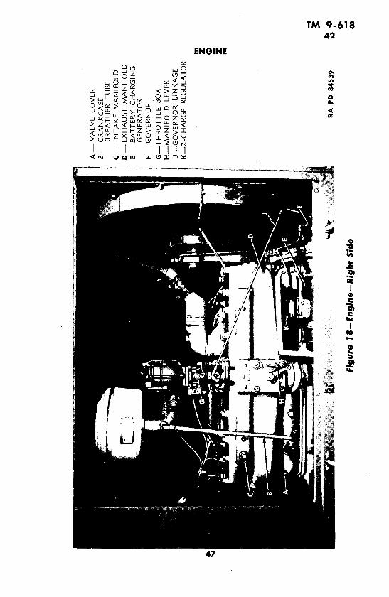
a. Construction. The gasoline engine (figs. 16, 17 and 1.8) is a6-cylinder, L-head type, with aluminum pistons. The cylinder blockand crankcase are cast in one piece, and the water jacket extends the
44

TM 9-61842
ENGINE
TIMING GEAR CASE
FAN BELT
FRONT ENGINE SUPPORT
ENGINE FRAME
MUFFLER RA PD 56900
Figure 16-Engine-With Radiator and Canopy Removed-Front View
full length of the cylinder bore. The cylinder head is made of castiron, and is easily removable to permit service operations.
b. Accessories.(1) WATER PUMP. The water pump is attached to the left side of
the engine block on the accessory drive (fig. 17).
(2) FUEL PUMP. The fuel pump is on the right side of the-engine,back of the exhaust pipe (fig. 41).
45

TM 9-61842
GENERATING UNIT M7
I-
Z9 ,I UIo w w > °.>,
'Ouw> L< Z
rz~'~a I , az~ z
z- - I o - - , w z- _z I i, .\E Z -: --
11LL I I<71 < o U1- w
4-
0-
46
_~~~~~~~~~~~~~~~~~~~~~1
*, H. \* i ~~~~~~~~~~~
R . Hi__~~(
TM 9-61842
ENGINE
wO~(O
S o- D I -Y
<0 c o LL WZP
47 ~~~~~~~~'.
I:
47~~~~~

TM 9-61842
GENERATING UNIT M7
(3) MANIFOLD. The combination exhaust and intake manifold ison the right side of the engine block (fig. 18).
(4) MUFFLER. The muffler is strapped to the frame at the right ofthe engine (fig. 35).
(5) OIL FILTER. The oil filter is on the left side of the engine, abovethe accessory drive (fig: 17).
(6) THERMOSTAT. The thermostat is in the water outlet line to theradiator on top of the engine (fig. 30).
(7) THROTTLE Box. The throttle box is mounted on the inl:ake sec-tion of the manifold at right of engine (fig. 18).
(8) CARBURETOR. The carburetor is mounted on the throttle boxat right of engine (fig. 45). r
(9) AIR FILTER. The air filter is mounted on the carburetor elbowabove the manifold (fig. 46).
(10) BATTERY-CHARGING GENERATOR. The battery-charging gen-erator is located under the manifold at the right side of engine (fig. 61).
(11) GOVERNOR. The governor is at the right side of the engine, infront of the battery-charging generator (fig. 61).
(12) TACHOMETER DRIVE. The tachometer drive is mounted on aflange above the accessory drive on the left side of the engine (fig. 17).
(13) DISTRIBUTOR. The distributor is mounted on the tachometerdrive on the left side of engine (fig. 17).
(14) IGNITION COIL. The ignition coil is mounted on a bracketheld down by an engine cylinder cap screw head on the left side ofengine (fig. 17).
(15) STARTING MOTOR. The starting motor is at the left of theengine block mounted on the bell housing (fig. 17).
c. Functioning. The engine is of the internal combustion, 4-strokecycle, automotive type. Fuel is drawn into the fuel pump from thefuel tank, and then forced through to the carburetor to be mixed withthe right quantity of air. The mixture goes into the intake section ofthe manifold, where it is drawn into each cylinder at the proper timeby the down, or intake, stroke of the piston. It is then compressed bythe upward, or compression, stroke, and ignited by a spark as thepiston reaches the top point of travel. The expansion of the burninggases forces the piston down for the power stroke. Before the pistonreaches bottom, the exhaust valve opens, and as the piston returns inthe exhaust stroke, it forces the burned gases through, into the ex-haust section of the manifold, and out by way of the muffler. The com-plete cycle of four piston strokes results in two revolutions of thecrankshaft. Successive firing in the six cylinders results in a steadyimpelling force on the crankshaft.
48

TM 9-61842-43
ENGINE
d. Specifications.Make ..................................... Hercules gasolineModel ........................................... WXLC-3Type .' ........................................... L-headNumber of cylinders .................................... 6Bore ............... ............................ 41/4 in.Stroke ..... ............................... 4 3/4 in.Piston displacement .............................. 404 cu. in.Compression ratio .................................. 6.35 to 1Firing order ..................................... 1-5-3-6-2-4Maximum horsepower at rated speed ........... 67 hp at 1,200 rpmCrankcase capacity ..................................... 7 qtCooling system capacity ................... .......... 36 qtWeight (with accessories) .............................. 945 lb
43. TROUBLE SHOOTING.a. Engine Fails To Start.
Possible Cause Possible RemedyLack of fuel. Supply fuel.Clogged fuel line. Clean fuel line.No spark. Check distributor points, con-
denser, and ignition coil.b. Engine Stops.
Too heavy load on cold engine. Remove load, and warm up en-gine.
Lack of fuel. Supply fuel.Clogged fuel line. Clean fuel line.Fuel leak. Check fuel line.No spark. Check distributor points, con-
denser, and ignition coil.c. Engine Runs Irregularly or Misfires.
Dirt or water in fuel line. Clean fuel line, strainer, andsediment cup.
Cylinder or cylinders not firing. Replace spark plugs.Spark plugs defective.
Too rich mixture. Adjust idling speed mixture ad-justing screw.
Manifold air leak. Replace gasket or manifold.Faulty governor adjustment. Adjust governor.
d. Overheating.Clogged oil line. Clean out oil line.Thermostat stuck closed. Service, or replace thermostat.
e. Popping, Spitting, or Spark Knock.Excessive carbon deposits. Report to ordnance personnel.Spark plug gaps too wide. Close gaps to 0.025 inch.Dirt on spark plug porcelain. Wipe clean.
49

TM 9-61843-45
GENERATING UNIT M7
f. Poor Compression.Possible Cause Possible Remedy
Loose spark plugs. Tighten plugs in head, or replace.Cylinder head loose. Tighten head.Cylinder head gasket leaking. Report to ordnance personnel.
g. Lack of Power.Low or poor compression. See step f, above.Air cleaner restricted. Clean mesh element.Overheating. Thermostat stuck Service, or replace.
closed.Improper mixture. Adjust carburetor screw.
44. MAINTENANCE.
a. Inspection and Adjustments. Section III covers general in-spections which include the engine. Under "Trouble Shooting," para-graph 43, are given specific checks for various sorts of engines faults.
45. TUNE-UP.a. Procedure.(1) One of the most important operations in the maintenance of
the engine is proper engine tune-up. This operation, more than anyother, determines whether or not the engine delivers the.:maximumin performance and economy. Only by accurately making the follow-ing checks and adjustments can the maximum performance of theengine be obtained.
(2) COMPRESSION.
(a) Before making any checks on the engine, it should be run forseveral minutes to warm it up, and lubricate the valve mechanism.The compression of the engine should be checked first when tuning,because an engine with uneven compression cannot be tuned success-fully.
(b) Remove all spark plugs. The ignition should be turned off, withthe governor throttle valve in the "OPEN" position.
(c) Insert the compression gage in a spark plug hole, arnd hold ittightly. Crank the engine with the starting motor until the gagereaches its highest reading, which requires only a few turns. Repeatthe same test on all cylinders, and make a note of the compression oneach.
(d) The compression on all cylinders should be 110 pounds persquare inch or better, and all cylinders should read approximatelythe same, within 5 to 10 pounds, for satisfactory engine performance.
(e) Should one or more cylinders register low compression read-ings, notify ordnance maintenance, as a mechanical defect has de-veloped beyond the using arms scope of repair.
50
TM 9-61845
ENGINE
(3) SPARK PLUGS. Remove, clean, and adjust all spark plugs (par.79).
(4) BATTERY TEST.
(a) Connect the negative terminal of a voltmeter to the startingswitch terminal, and the positive terminal of the voltmeter to a goodground.
(b) Rotate the engine with the starting motor for 15 seconds. Ifthe starting motor turns the engine over at a good rate of speed withthe voltmeter reading 5 volts or better, it indicates a satisfactorystarting circuit, which includes the condition of the battery, terminals,and cables. However, if it turns over slowly, or the voltmeter readingis under 5 volts, the starting motor, battery, and battery cableterminals should be checked individually to locate the source of thetrouble (sec. XIV).
(5) DISTRIBUTOR.
(a) Remove the spark plug wires from the distributor cap, andexamine the terminals for corrosion. The wires should also be checkedfor damaged insulation and for being oil-soaked.
(b) Remove the distributor cap, and check the cap and distributorrotor for cracks or burned contacts.
(c) Check the automatic advance mechanism, by turning the dis-tributor cam in a clockwise direction as far as possible, and releasingthe cam to see if the springs return it to its retarded position. If thecam does not return readily, report to ordnance personnel.
(d) Examine the distributor points. Dirty points should be cleaned,and pitted or worn points should be replaced. Check the points foralinement, and aline them, if necessary.
(e) Hand crank the engine until cam follower rests on a peakof the cam. Adjust the point gap to between 0.019 and 0.021 inch,using feeler gage. This operation must be performed very accurately.Hand crank engine until the cam follower is located between thecam peaks. Hook the end of a point scale over the movable point, andpull steadily on the spring scale until the points just start to open.Correct spring tension is between 18 and 21 ounces.
(f) Install distributor cap and spark plug wires. Make sure that theterminals of the primary wire from the ignition coil to the distributorare clean and tight.
(6) FUEL PUMP. Remove the sediment cup and screen and washthem thoroughly in SOLVENT, dry-cleaning. When assembling, makesure that the cork gasket is in good condition, and properly seated.Tighten all fuel pump connections.
(7) AIR FILTER.(a) Remove the air filter from the carburetor. Remove the wing
nut from the top of the filter and take off the cover.
51

TM 9-61845
GENERATING UNIT M7
Figure 19-Timing Hole in Engine Bell Housing
(b) Empty the oil out of the filter, and clean out all oil and accumu-lated dirt. Wash body with SOLVENT, dry-cleaning and wipe dry.Wash filter element by slushing up and down in SOLVENrT, dry-cleaning. Dry thoroughly, either with an air hose or by letting it standuntil dry. Fill the body of the filter to bend level with OII,, engine(seasonal grade).
(c) Install the filter on the carburetor elbow. Tighten clamp.
(8) CARBURETOR. The only carburetor adjustment that should beattempted by using arms is with the idling speed mixture adjustingscrew. This controls the fuel mixture to the engine while the engineis operating at idle speed only (fig. 45).
(9) IGNITION TIMING. NOTE: Timing should be checked underthe supervision of ordnance personnel. Attach one wire of the neontiming light to No. 1 spark plug, and the other wire to the No. 1 sparkplug wire. Start the engine and run it at idling speed. Loosen distribu-tor clamp and slightly rotate distributor body clockwise or counter-clockwise until the entire white dot on the flywheel (fig. 19) is visiblethrough the timing hole in the flywheel housing each time the lightgoes on.
(10) COOLING SYSTEM. Tighten all hose connections, and examinefor any indications of water leaks. Check the fan and exciter belts forcracks, oil soaking, and for proper tension.
52
TM 9-61846-47
Section X
COOLING SYSTEMParagraph
Description ........................................ 46Trouble shooting ................................... 47Cleaning ................ .......................... . 48Radiator .................................. 49Fan ................................ 50Fan belt ...... 5 ........................... 51Water pump ....................................... 52Thermostat ......... ......... ...... 53
46. DESCRIPTION (fig. 20).a. Construction. The water-cooling system consists of the radia-
tor (fig. 22), thermostat (fig. 30), fan assembly, centrifugal waterpump, and the connecting lines and hose. The water capacity is 36quarts. The system may be drained by opening a drain cock locatedin the water outlet pipe connected to the bottom of the radiator (fig.21). The fill cap is in the usual position at the top of the radiator.
b. Functioning. The pump circulates cooled water from thebottom of the radiator through the channels in the water jacket andcylinder head. The water heated in the water jacket is forced throughthe radiator inlet into the upper radiator tank, flows down the radiatortubes for cooling, and is redrawn into the pump to complete the cycle.Air, drawn through louvers and up through the frame, passes acrossthe engine, and is forced out of the unit through the radiator fins bythe action of the fan, thereby cooling the water. On the top of theengine, at the point where the water returns to the radiator, is athermostat whose function is to keep cool water from entering theradiator, by forcing it to return directly to the pump through the by-pass tube until the engine is warmed up.
47. TROUBLE SHOOTING.a. Overheating.
Possible Cause Possible Remedy
Leaks in system. Service or replace faulty hose,clips, gaskets, or pipe.
Radiator dirty inside or out. Clean radiator thoroughly.Dirty water. Drain, and refill with clean
water.Clogged system. Flush system, from top of en-
gine down.Clogged radiator. Service, or report to ordnance
personnel for replacement.Leaky radiator. Report to ordnance personnel.Thermostat stuck closed. Service, or replace.
53
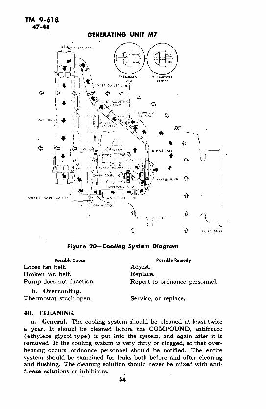
TM 9-61847-48
GENERATING UNIT M7
C)9 1 , \ \THERMOSTAT THERMOSTATI i |\ OPEN CLOSED
WATER OUTLET LINE
IF ' ./B ELT ADJUSTINGSCREW
Ok t > THERMOSTAT
RADIATOR _ HOUSING
CHAIN COUPLIN G
ACCESSORY ORIVE A
RADIATOR OVERFLO? PIPE = LINE
DRAI CK
Figure 20-Cooling System Diagram
Possible Cause Possible Remedy
Loose fan belt. Adjust.Broken fan belt. Replace.Pump does not function. Report to ordnance personnel.
b. Overcooling.Thermostat stuck open. Service, or replace.
48. CLEANING.
a. General. The cooling system should be cleaned at least twicea year. It should be cleaned before the COMPOUND, antifreeze(ethylene glycol type) is put into the system, and again after it is
removed. If the cooling ystem is very dirty or clogged, so hat over-h ea s not function. Repoccurs, ordnance personnel. entiresystem should be examined for leaks both before and after cleaningand flushing. The cleaning solution should never be mixed with anti-freeze solutions or inhibitors.
54
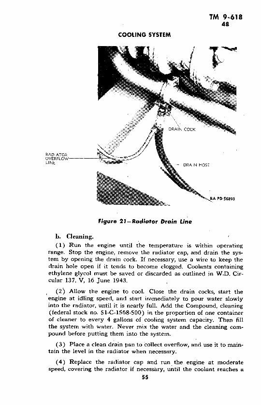
TM 9.61848
COOLING SYSTEM
Rflop ^ DRAIN COCK
RADIATOROVERFLOWLFINE 2 -R it DRAIN HOSE
RA PD 56893
Figure 21-Radiator Drain Line
b. Cleaning.(1) Run the engine until the temperature is within operating
range. Stop the engine, remove the radiator cap, and drain the sys-tem by opening the drain cock. If necessary, use a wire to keep thedrain hole open if it tends to become clogged. Coolants containingethylene glycol must be saved or discarded as outlined in W.D. Cir-cular 137, V, 16 June 1943.
(2) Allow the engine to cool. Close the drain cocks, start theengine at idling speed, and start immediately to pour water slowlyinto the radiator, until it is nearly full. Add the Compound, cleaning(federal stock no. 51-C-1568-500) in the proportion of one containerof cleaner to every 4 gallons of cooling system capacity. Then fillthe system with water. Never mix the water and the cleaning com-pound before putting them into the system.
(3) Place a clean drain pan to collect overflow, and use it to main-tain the level in the radiator when necessary.
(4) Replace the radiator cap and run the engine at moderatespeed, covering the radiator if necessary, until the coolant reaches a
55

TM 9-61848
GENERATING UNIT M7
temperature above 180 degrees F but not over 200 degrees F. Donot allow the level in the radiator to drop low enough to interferewith the circulation.
(5) Stop the engine after it has run for 30 minutes within the180-degrees F to 200-degrees F range. Then, remove the radiator cap,and drain the system completely.
c. Neutralizing.
(1) Allow the engine to cool. Close the drain cock, run the engineat idling speed, and commence immediately to pour water slowly intothe radiator. Pour until it is nearly full. Add the neutralizer com-pound (federal stock no. 51-C-1568-500) in the proportion of onecontainer of neutralizer to every 4 gallons of cooling system capacity.Then fill the system with water.
(2) With the radiator covered, run the engine for at least 5 min-utes at operating temperature. Then stop the engine.
(3) Drain the system completely by removing the radiator capand opening the drain cock.
d. Flushing.(1) Allow the engine to cool. Close the drain cock, start the engine,
and fill the system with water immediately.-
(2) Run the engine until the coolant is heated to operating tem-perature.
(3) Drain the system by removing the radiator cap and openingthe drain cock. Repeat the flushing operation until the drain wateris clean.
(4) Clean all sediment from the radiator cap valves and the over-flow pipe. Blow insects and dirt from radiator core air passages withcompressed air, blowing from the rear. Use water, if necessary, tosoften obstructions.
e. Leaks. After completing flushing operation and before pour-ing appropriate coolant into cooling system, allow engine to cool.Start the engine, and immediately fill the system with coolant. Stopthe engine when the cooling system is completely full. Then examinethe entire cooling system for leaks. The cleaning solution oftenuncovers leaks which already exist but are plugged with rust or cor-rosion.
f. Coolant Service.
(1) When servicing the vehicle for summer, nearly fill the systemwith clean water. Add Compound, inhibitor, corrosion (federal stockno. 51-C-1600) in the proportion of one container of inhibitor to each4 gallons of cooling system capacity. Then fill the system with water.
56

TM 9-61848-49
COOLING SYSTEM
WATER OUTLET CONNECTION- _-
OVERFLOW TUBE A-'
WATER INLET CONNECTION
-/ RA PD 56918
Figure 22--Radiator and Support-Rear' View
(2) When servicing for winter, fill the system about one-quarterfull of clean water. Add sufficient COMPOUND, antifreeze (ethyleneglycol type) for protection against the lowest temperature likely tobe encountered. Nearly fill the system with water, and run the engineuntil normal operating temperature is reached. Then add sufficientwater to fill the system to the proper height (par. 28).
49. RADIATOR (fig. 22).a. Description. The radiator is of the 3-piece, heavy-duty tractor
type, and is mounted on.the frame in front of the engine where itacts as front support for the canopy roof.
b. Trouble Shooting.(1) OVERHEATING.
Possible Cause Possible Remedy
Leaky radiator. Report to ordnance personnel.Clogged radiator. Clean, or report to ordnance per-
sonnel for replacement.Radiator dirty, inside or out. Clean radiator.
57

TM 9-61849-50
GENERATING UNIT M7
, .-
RA PD 56919
Figure 23-Fan Guard Removal
c. Maintenance. Radiator and all connections should be fre-quently inspected for leaks.
50. FAN.a. Description. The fan assembly is made up of the fanl, the fan
shaft, a pulley, and an adjustable mounting bracket. The fan belt is7/8 inch wide, and 54 inches long.
h. Trouble Shooting.(1) FAN STOPS.
Possible Cause Possible Remedy
Broken belt. Replace.(2) BELT SLIPS.
Loose belt. Tighten with lifting screw.(3) EXCESSIVE NOISE.
Defective bearing. Replace fan assembly.
c. Maintenance. The fan does not need special attention. Screwsshould be kept tight, and the whole assembly kept clean and properlylubricated (fig. 24).
d. Removal.(1) REMOVE FAN BELT FROM PULLEY. Loosen lock nut on
58

TM 9-61850-51
COOLING SYSTEM
F-----AN GUARD
'PLUG(SOME MODELS
WITH OILER)
FAN BELTR
SCREW
LOCK NUT
FAN BRACKET
FAN GUARD 'BRACE
RA PD 84536
Figure 24-Fan Hub Screw Plug Grease Fitting
mounting bracket screw. Turn screw until fan belt is loose enoughto be slipped off top pulley.
(2) REMOVE FAN GUARD (fig. 23). Take out screws, nuts, andlock washers holding the two sections of the guard together. Take offnuts and lock washers attaching the two guard sections to the shroud,and lift out guard.
(3) REMOVE FAN AND BRACKET. Take out base cap screws andlock washers holding bracket to engine, and lift off fan assembly.
e. Installation.(1) ATTACH FAN AND BRACKET. Attach fan bracket to engine with
cap screws provided.(2) INSTALL FAN BELT. Bring fan belt up over fan onto fan pulley
(fig. 26), then onto pulley at end of accessory drive. Turn adjustingscrew (fig. 25) until the amount the fan belt can be deflected at acenter point between pulleys measures from 1/2 to 3/4 inch. Tightenlock nut against bracket.
(3) ATTACH FAN GUARD. Place guard sections in position, andsecure to fan shroud with lock washers and nuts on the projectingbolts. Fasten sections together with machine screws, lock washers,and square nuts.
51. FAN BELT.a. General. For best results, the fan belt should be kept free of
59

TM 9-61851-52
GENERATING UNIT M7
RA PMI 56920
Figure 25-Adjusting Fan Belt
dirt, grease, and oil. Its adjustment should be checked frequently.Fan belt is properly adjusted when it can be deflected from l/2 to 3/4
inch at a center point between pulleys (fig. 25).
h. Removal.(1) REMOVE FAN BELT FROM PULLEY (par. 50 d (1)).(2) REMOVE FAN GUARD (par. 50 d (2)).(3) REMOVE BELT. Take belt off lower pulley, and remove it by
bringing it down over fan.
c. Installation. For instructions on installing fan belt, see para-graph 50 e, (2) and (3).
52. WATER PUMP.a. Construction. The centrifugal water pump is mounted, on the
left side of the engine. It is driven by the accessory drive to which itis attached by a chain coupling. Four packing rings (split-ring type),tightened by a packing nut against a gland, seal the water pump atthe shaft end.
b. Functioning. The impelling force of the water pump circulatesthe cooled water from the bottom of the radiator through the entirecooling system (fig. 20).
60

TM 9-61852
COOLING SYSTEM
I
RA PD 56952Figure 26-Fan Belt Installation
c. Maintenance. The water pump should be lubricated as speci-fied in section IV. A leak developing at the water pump packing nutcan be stopped by tightening the nut; however, care must be takennot to tighten the nut with considerable force. Water pump must berepacked if packing nut is turned up its full thread and leaking con-tinues. New packing will not stop the leak at the shaft if the shaft isworn. The pump must be replaced. Any other trouble with the waterpump necessitates replacement of the complete unit.
d. Repacking.(1) Drain cooling system.
(2) Unscrew packing nut, pry out packing gland, and remove oldpacking. The four packing rings are removed by prying them outof the housing.
(3) Place a new split-ring packing on the shaft, and, using thepacking gland, push it into the pump housing. Continue this pro-cedure until four packing rings are inserted in the pump housing.
(4) Push packing gland into position over packing in pump hous-
61
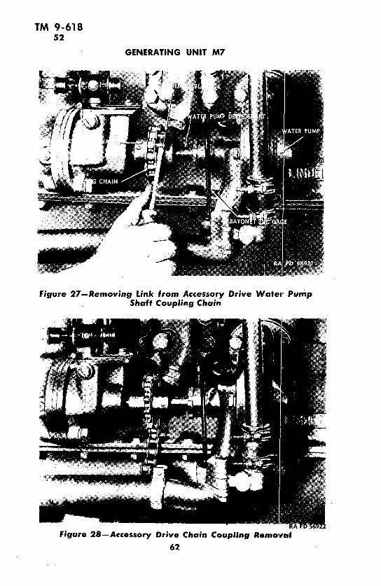
TM 9-61852
GENERATING UNIT M7
Figure 27-Removing Link from Accessory Drive Water PumpShaft Coupling Chain
Figure 28-Accessory Drive Chain Coupling Removal
62

TM 9-61852-53
COOLING SYSTEM
'ing, and screw packing nut over gland onto pump body. Do nottighten nut with any considerable force.
(5) Refill cooling system, start engine, and check for a leak at thepump. If a leak exists, tighten packing nut while engine is running.
e. Removal.(1) DRAIN COOLING SYSTEM (par. 53 c(1)).
(2) REMOVE WATER PUMP ELBOW. Loosen clamp screw holdinghose section to water pump elbow. Take out cap screws fitting waterpump elbow to water pump.
(3) REMOVE BYPASS PIPE. Loosen clamp screws holding top andbottom hose sections to bypass pipe, and remove pipe.
(4) SEPARATE CONNECTION WITH ACCESSORY DRIVE. Separatecoupling chain attaching pump drive to accessory drive by forcing outremovable link (figs. 27 and 28).
(5) REMOVE PUMP. Take out cap screws and lock washers holdingwater pump and gasket to engine block.
f. Installation.(1) INSTALL PUMP. Attach pump and gasket in position on side
of engine block with the three cap screws and lock washers provided.
(2) CONNECT WITH ACCESSORY DRIVE. Bring coupling chainaround coupling sections, and lock in, place by inserting removablelink.
(3) INSTALL BYPASS PIPE. Connect top of bypass pipe to thermo-stat housing with the rubber hose. Tighten clamp screws, connectbottom of bypass pipe to the water pump connection by the hose sec-tion, and tighten clamp screws.
(4) INSTALL WATER PUMP ELBOW. Insert pipe end of elbow inrubber hose in bottom water line. Bring flanged end to water pump,and install cap screws and lock washers provided. Tighten strap screwholding hose to pipe.
53. THERMOSTAT.a. Construction. The thermostat is a plug-type, temperature-
relief fitting, set in a split elbow housing in the upper radiator line tothe engine.
b. Functioning. Until the water in the engine reaches a tem-perature of 150 degrees F, the thermostat keeps this water fromcirculating through the radiator, thus decreasing the "warming up"period. At 150 degrees F, the thermostat begins to open: at 180 degreesF it is fully open. While the thermostat is closed, the water circulatedthrough the engine by the pump is shunted off through the bypass lineback to the pump.
63

TM 9-61853
GENERATING UNIT M7
Figure 29-Taking Apart Thermostat Housing
Figure 30-Thermostat--Section of Housing Removed64

TM 9-61853-54
EXHAUST SYSTEM
e. Removal.(1) DRAIN WATER LINES. Open drain cock in radiator outlet pipe
(fig. 21). This will drain engine, radiator, and water lines.(2) DISCONNECT BYPASS PIPE. Loosen screws on wire clamps
holding hose to thermostat housing, and disconnect bypass pipe.(3) SEPARATE RADIATOR CONNECTION TO THERMOSTAT HOUSING.
Loosen screws holding clamps on hose, and remove hose.(4) SEPARATE THERMOSTAT HOUSING (fig. 29). Take out the cap
screws and lock washers through the flanges of the thermostat housing.The thermostat may now be removed from the 'free half of the housing(fig. 30).
d. Maintenance. The thermostat is entirely enclosed, and or-dinarily needs no attention. To find out if the thermostat is functioningproperly, place it with a thermometer in a pan of water, and begin toheat the water. The thermostat should begin to open when the ther-mometer indicates 150 degrees F, and should be fully opened at 180degrees F.
e. Installation.(1) INSTALL THERMOSTAT IN HOUSING. Insert thermostat in the
half of thermostat housing closest to the radiator, in the flanged end,with the coil showing.
(2) CONNECT HOUSING WITH WATER LINES AND BRING SECTIONS
TOGETHER. Insert small end of free section of thermostat housing intorubber hose connecting to top of radiator, and bring flanged ends ofhousing halves together, first putting gasket in place. Bolt togetherwith cap screws and lock washers. Tighten bolt on strap holding hoseto thermostat housing. Bring hose at end of bypass line over nipple onthermostat housing, and tighten clamp bolt.
Section XI
EXHAUST SYSTEM
Paragraph
Description . . ......... .............. 54Trouble shooting .................................... 55Manifold .......................................... 56Exhaust pipe ....................................... 57Muffler ............................................ 58Flexible tube ......................................... 59
54. DESCRIPTION.a. Constructicn. The exhaust system (fig. 31) is made up of the
exhaust section of the manifold, the pipe connection between mufflerand manifold, the muffler (fig. 36), and the flexible tube that is at-tached to the outside end of the muffler when the unit is in operation.
65

TM 9-61854
GENERATING UNIT M7
-v
a
DD C 0
T ( a
o
e.

TM 9-61854-56
EXHAUST SYSTEM
b. Functioning. The burned gases resulting from the ignition ofthe mixture of gasoline and air in the cylinders are forced by the ex-haust stroke of the pistons out of the cylinders, into the manifold, andaway from the unit by way of the exhaust pipe, the muffler, and theexhaust tube.
55. TROUBLE SHOOTING.a. Popping, Spitting, Spark Knock.
Possible Cause Possible Remedy
Manifold heat control defective. Adjust (under supervision).
h. Exhaust Fumes.Leaking manifold gasket. Tighten or replace.Blown-out manifold gasket. Replace.Burnt-out muffler. Replace muffler.
c. Excessive Noise.Crack between intake and ex- Replace manifold.
haust manifolds.Burnt-out muffler. Replace muffler.
56. MANIFOLD.a. Description. The intake and exhaust manifold, along the right-
hand side of the engine block, is of 1-piece construction. The topsection is the intake, where the mixture of gasoline and air enters thecylinders. Preheating of the mixture is accomplished by an openingthat allows the hot exhaust gases to strike the intake manifold wall.The size of this opening can be adjusted by a lever on the face of themanifold (fig. 32). A spring holds this lever in its correct position,and the setting should not be changed except by permission of higherauthority.
b. Maintenance. The manifold should be frequently inspectedfor cracks. When engine troubles develop that might have beencaused by manifold cracks which are not apparent, the manifoldshould be taken off and thoroughly inspected. Check bolts for tight-ness. Check collar gasket. When replacing, use new gasket. Thor-
-oughly scrape off old gasket.
c. Removal.(1) LOOSEN CHARGING GENERATOR (fig. 62). Loosen lock nut on
set screw holding charging generator. Loosen set screw, and turncharging generator until the regulator at top is at right angles to itsformer position. Tighten lock nut.
(2) REMOVING CHARGING GENERATOR GUARD (fig. 63). Take outcap screws holding asbestos lined charging generator guard in place,and remove guard.
67

TM 9-61856
GENERATING UNIT M7
RA PD 56926
Figure 32-Manifold Lever and Holding Spring
68
t _ AM_~~~~~~~~~~~~~~~~~-·
, WE! l
68

TM 9-61856
EXHAUST SYSTEM
RA PD 56927
Figure 33-Manifold Removal
(3) DISCONNECT BREATHER PIPE. Take out cap screw and lockwasher holding breather pipe connection to valve cover.
(4) UNCOUPLE GOVERNOR LINKAGE ROD. Take off nut fastening
governor linkage rod to governor aim. Do not disconnect at thethrottle box.
(5) REMOVE CARBURETOR AND THROTTLE Box. Take out the twocap screws and lock washer holding the throttle box to the manifoldflange, and remove carburetor, throttle box, and air cleaner as oneunit.
(6) LOOSEN EXHAUST PIPE FROM MANIFOLD. Take out the threecap screws and lock washers holding together the two lower manifoldflanges. Loosen lock bolt through manifold flange.
(7) REMOVE MANIFOLD (fig. 33). Take the nuts from the 10studs that hold the manifold to the engine block, and remove manifoldand gaskets.
d. Installation.(1) ATTACH MANIFOLD TO ENGINE. Bring manifold, with new
gaskets affixed, into position against the engine wall with the enginestuds in place through the manifold slots. Bring the lower flange orcollar of the manifold down over the exhaust pipe. Make sure the
69
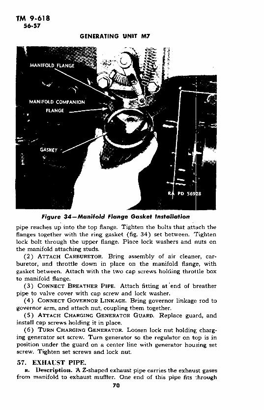
TM 9-61856-57
GENERATING UNIT M7
Figure 34-Manifold Flange Gasket Installation
pipe reaches up into the top flange. Tighten the bolts that attach theflanges together with the ring gasket (fig. 34) set between. T'ightenlock bolt through the upper flange. Place lock washers and nuts onthe manifold attaching studs.
(2) ATTACH CARBURETOR. Bring assembly of air cleaner, car-buretor, and throttle down in place on the manifold flange, withgasket between. Attach with the two cap screws holding throttle boxto manifold flange.
(3) CONNECT BREATHER PIPE. Attach fitting at'end of breatherpipe to valve cover with cap screw and lock washer.
(4) CONNECT GOVERNOR LINKAGE. Bring governor linkage rod togovernor arm, and attach nut, coupling them together.
(5) ATTACH CHARGING GENERATOR GUARD. Replace guard, andinstall cap screws holding it in place.
(6) TURN CHARGING GENERATOR. Loosen lock nut holding; charg-ing generator set screw. Turn generator so the regulator on top is inposition under the guard on a center line with generator housing setscrew. Tighten set screws and lock nut.
57. EXHAUST PIPE.a. Description. A Z-shaped exhaust pipe carries the exhaust gases
from manifold to exhaust muffler. One end of this pipe fits t:hrough
70
TM 9-61857-58
EXHAUST SYSTEM
the manifold companion flange, through a ring gasket, and into themanifold lower flange. A horizontal hexagonal-head set screw throughthe manifold flange holds the pipe firmly in place. The companionflange bolts to the manifold flange. The pipe fits into the mufflerthrough a collar provided with a tightening strap that holds the twosecurely together. The two long sections of the pipe are covered withwoven asbestos sheeting, held in place by metal straps.
b. Maintenance. Examine exhaust pipe regularly for cracks. Takeparticular note of welded joints. Test regularly for tightness of con-nections with muffler and manifold. Clean out at regular intervals.
c. Removal.(1) REMOVE EXHAUST GUARD TRAY. Loosen the four screws at-
taching expanded metal exhaust guard tray to tabs, and remove tray.(2) DISCONNECT EXHAUST PIPE FROM MANIFOLD. Loosen mani-
fold companion flange cap screws. Remove manifold upper flange re-taining screw. Remove exhaust pipe from manifold flanges. If pipewill not come free, the next operation will automatically release it.
(3) REMOVE MUFFLER AND EXHAUST PIPE. Unscrew nuts at bothends of muffler strap screws, and remove straps and muffler.
d. Installation.(1) CONNECT EXHAUST PIPE TO MANIFOLD (fig. 35). Loosen
manifold companion flange cap screws. Loosen manifold flange re-taining screw. Slide exhaust pipe into place through manifold flanges.Tighten lower flange cap screws.
(2) INSTALL EXHAUST GUARD TRAY. Attach exhaust guard trayto engine by loosening the side cap screws attaching oil pan to engineover the exhaust pipe, and sliding the four metal tabs attached to theguard under the cap screw heads. Tighten cap screws.
58. MUFFLER.
a. Construction. The exhaust muffler (fig. 36), a long steelcylinder, is strapped to the frame at the right of the engine. One endhas a right-angle pipe connection fitted with an adjustable strap col-lar for holding to the exhaust pipe. The other end is fitted with a 2-inch pipe extending beyond the muffler to receive the flexible exhausttube.
b. Functioning. The muffler deadens the sound and shock ofthe exhaust by means of an arrangement of baffles, tubes, and passages.
c. Maintenance. The only requirements for muffler maintenanceare inspection for cracks or evidence of burning out and checking fortightness of connections. Troubles or defects call for immediate re-placement.
d. Removal. For instructions on removing muffler, see paragraph57 c.
71
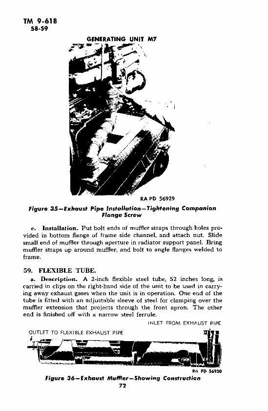
TM 9-61858-59
GENERATING UNIT M7
RA PD 56929
Figure 35-Exhaust Pipe Installation-Tightening CompanionFlange Screw
e. Installation. Put bolt ends of muffler straps through holes pro-vided in bottom flange of frame side channel, and attach nut. Slidesmall end of muffler through aperture in radiator support panel. Bringmuffler straps up around muffler, and bolt to angle flanges welded toframe.
59. FLEXIBLE TUBE.
a. Description. A 2-inch flexible steel tube, 52 inches, long, iscarried in clips on the right-hand side of the unit to be used in carry-ing away exhaust gases when the unit is in operation. One end of thetube is fitted with an adjustable sleeve of steel for clamping over themuffler extension that projects through the front apron. The otherend is finished off with a narrow steel ferrule.
INLET FROM EXHAUST PIPE
OUTLET TO FLEXIBLE EXHAUST PIPE
RA PD 56930Figure 36--Exhaust Muffler--Showing Construction
72

TM 9-61860-61
Section XII
FUEL SYSTEM
Paragraph
Description ........... ................... . 60Trouble shooting ................................ .. 61Fuel tank ............. ........ ................... 62Fuel pump....................................... 63Carburetor ..................................... ... 64Air cleaner ....................................... 65Governor .......................................... 66Throttle box ........................................ 67
60. DESCRIPTION (fig. 37).
a. Construction. The fuel system consists of the fuel tank witha flame-proof filler cap and screen (fig. 38), and a mechanical, float-type fuel gage (fig. 39), the fuel pump, the carburetor, the air cleaner,the intake section of the manifold, the governor, the throttle box,linkage between governor and throttle box, a ,/ ;-inch fuel line (fig.40), and a 1/4-inch drain line. The capacity of the fuel tank is 26gallons. ·
b. Functioning. Suction action of the fuel pump brings the fuelfrom the tank to the pump, which then forces it to the top of the car-buretor, where it is sprayed into the air intake to form an air and fuelvapor mixture. The suction of the engine pistons pulls the air throughthe air cleaner into the carburetor where it picks up fuel vapor. Themixture is then drawn through the throttle box to the intake section ofthe manifold. The governor (fig. 47), operated from the timing gear,is set to hold the engine at a predetermined speed. The choke, oper-ated manually from the instrument panel, regulates the air supply,and thereby makes the fuel mixture lean or rich. The throttle, alsooperated manually from the instrument panel, reduces the amount ofmixture supplied to the engine.
61. TROUBLE SHOOTING.
a. Many symptoms which might be attributed to the fuel systemare in reality due to faulty ignition. Before attempting any but theobviously required adjustments, check the ignition system thoroughly(par. 45).
b. Engine Will Not Start.Possible Cause Possibly Remedy
Dirt or water in system. Clean sediment cup. Clean fuelpump strainer. Disconnectfuel lines, and blow them outwith air.
73

TM 9-61861
GENERATING UNIT M7
.,
0~~~~~~~
UJ~~~~~~
0
z
o >
M<
U
w -j 0
n u~u v%-
3~~~~~~~
LP~~~~~~~~~~~F-J
cl I ~~~w
U-
_7 4
Lu ~ ~~u
0<~~~~~~~~ <-
Z
Z)
.JJ
u
L74
< (DZu < < V~~~C~~~ 0 u~~
z F-
Z OLL
74
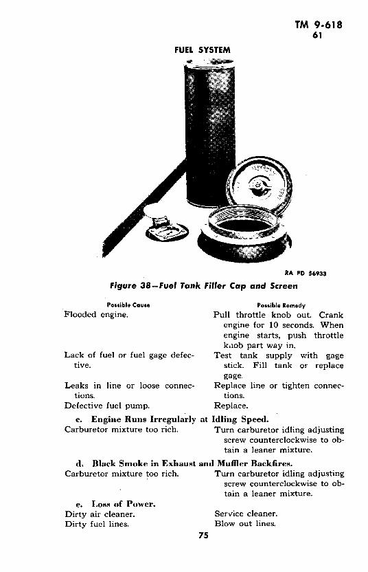
TM 9-61861
FUEL SYSTEM
RA PD 56933
Figure 38-Fuel Tank Filler Cap and Screen
Possible Cause Possible Remedy
Flooded engine. Pull throttle knob out. Crankengine for 10 seconds. Whenengine starts, push throttlekaob part way in.
Lack of fuel or fuel gage defec- Test tank supply with gagetive. stick. Fill tank or replace
gage.Leaks in line or loose connec- Replace line or tighten connec-
tions. tions.Defective fuel pump. Replace.
c. Engine Runs Irregularly at Idling Speed.Carburetor mixture too rich. Turn carburetor idling adjusting
screw counterclockwise to ob-tain a leaner mixture.
d, Black Smoke in Exhaust and Muffler Backfires.Carburetor mixture too rich. Turn carburetor idling adjusting
screw counterclockwise to ob-tain a leaner mixture.
e. Loss of Power.Dirty air cleaner. Service cleaner.Dirty fuel lines. Blow out lines.
75
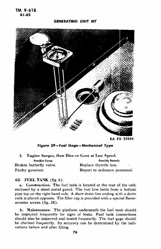
TM 9-61861-62
GENERATING UNIT M7
RA PD 56934
Figure 39-Fuel Gage-Mechanical Type
f. Engine Surges, then Dies or Goes at Low Speed.Possible Cause Possibly Remedy
Broken butterfly valve, Replace throttle box.
Faulty governor. Report to ordnance personnel.
62. FUEL TANK (fig. 6).
a. Construction. The fuel tank is located at the rear of the unit,enclosed by a sheet metal guard. The fuel line feeds from a bottompipe tap on the right-hand side. A short drain line ending with a draincock is placed opposite. The filler cap is provided with a special flame-arrester screen (fig. 38).
h. Maintenance. The platform underneath the fuel tank shouldbe inspected frequently for signs of leaks. Fuel tank connectionsshould also be inspected and tested frequently. The fuel gage shouldbe checked frequently. Its accuracy can be determined by the indi-cations before and after filling.
76

TM 9-61862-63
FUEL SYSTEM
RA PD 56936
Figure 40-Fuel Line at Tank-Showing Shut-off Cock
63. FUEL PUMP.a. Description. The fuel pump (fig. 41) is a mechanical, dia-
phragm-type, which is attached to the crankcase and operated by aneccentric on the engine camshaft. The vacuum created by the pumpdraws the fuel from the tank to the pump. The diaphragm then forcesthe fuel from the-pump to the carburetor. Before the fuel reachesthe pump proper, it flows through a strainer into a removable glasssediment cup where water and impurities fall to the bottom. The fuelflow passes across the top of this cup.
b. Trouble Shooting.(1) FUEL LEAKS.
Possible Cause Possible Remedy
Loose fuel sediment cup. Tighten cup thumb screw.Replace gasket, if necessary.
Loose fuel line fitting. Tighten inlet and outlet fit-tings. Replace, if fittings arestripped.
Loose fuel pump cover. Tighten cover screw.(2) Low FUEL PRESSURE.
Air leaks in system. Tighten connections.Clogged strainer. Service strainer.
77

TM 9-61863
GENERATING UNIT M7
RA PD 56937
Figure 41--Fuel Pump
Figure 42-Sediment Cup and Fuel Strainer Removal78

TM 9-61863
FUEL SYSTEM
RA PD 56939
Figure 43-Fuel Pump Removal (1)
(3) No FUEL PRESSURE.Possible Cause Possibly Remedy
Defective pump diaphragm. Replace pump.
c. Maintenance. The glass sediment cup should be examineddaily, and emptied whenever water is found at the bottom. The cupand the wire mesh strainer above it (fig. 42) should be cleaned fre-quently by washing in SOLVENT, dry-cleaning.
d. Removal.(1) DISCONNECT FUEL LINES FROM PUMP. Disconnect fuel tank
line and carburetor line at fuel pump.(2) REMOVE PUMP. Take out the two cap screws and lock wash-
ers that hold the pump to the engine, and remove pump (fig. 44).
e. Installation.(1) INSTALL PUMP. Install pump at slight upward angle to get
pump lever rod into its proper position on the camshaft. If someresistance is not met against the lever pressure, the lever rod is notriding against the cam, and the angle should be altered slightly andtried again. When the pump is correctly positioned, secure to enginewith cap screws and lock washers. Use new gasket when installingpump.
(2) CONNECT FUEL LINES TO PUMP. Connect fuel tank line andcarburetor line to fuel pump.
79

TM 9-61863
GENERATING UNIT M7
Figure 44-Fuel Pump Removal (2)
RA PD 56941
Figure 45-Idling Speed Mixture Adjusting Screw80

TM 9-61864
FUEL SYSTEM
64. CARBURETOR.a. Description. The carburetor (fig. 45) is a downdraft-type,
located over the intake section of the manifold above the throttle box.It is connected by a cast-iron elbow to the air filter. The fuel intakeis controlled by a float-regulated needle valve that maintains a con-stant fuel level in the chamber as the suction of the pistons draws themixture down to the intake manifold. At the top of the carburetor isan adjusting screw which controls the amount of air drawn in to theidling jet. This controls richness of the air and fuel mixture for idlingspeed only. The idling fuel vapor section of the carburetor is inoper-ative as soon as the main throttle is opened, and the engine has reachedhigh speed. Throttle and choke adjustment levers on the carburetorhave linkage connections to instrument panel knobs. that adjust theamount of air and fuel taken into the carburetor during starting andstopping.
b. Trouble Shooting.(1) ENGINE SPUTTER, REGULAR OR INTERMITTENT.
Possible Cause Possible Remedy
Carlburetor check valve stuck or Replace carburetor.defective.
(2) CHOKES AT IDLING SPEED..Flooded carburetor resulting from Replace carburetor.
stuck or defective check valve.
(3) BLACK SMOKE IN EXHAUST AND MUFFLER BACKFIRES.
Carburetor mixture too rich. Turn carburetor adjusting screwcounterclockwise for leanermixture.
(4) Loss OF POWER.Dirty air cleaner. Service cleaner.
(5) ENGINE SURGES, THEN DIES OR GOES AT Low SPEED.Broken butterfly valve. Replace throttle box.Faulty governor. Report to ordnance personnel.
(6) STICKING CONTROLS.Carburetor choke. Free valve shaft and linkage, and
lubricate.Carburetor throttle. Adjust choke control. Free shaft
and linkage, and lubricate.(7) Too RICH MIXTURE.
Carburetor choke not fully open- Free valve shaft, and lubricate.ing. Adjust choke control.
(8) ENGINE DIES.Engine will not idle. Adjust idling screw.
(9) FAST IDLING.Improper control adjustment. Adjust throttle control button
and throttle stop screw.
81
TM 9-61864-65
GENERATING UNIT M7
Possible Cause Possible RemedyCarburetor throttle stuck. Free shaft and linkage, and lubri-
cate.Bent or kinked tubing. Straighten, or replace tubing.Stopped up filter element. Clean or replace.Faulty fuel pump. Replace pump.Dirty fuel filter element. Clean and blow out filter ele-
ment.Dirty air cleaner. Clean.Fuel leaks at fuel filter. Tighten filter bowl. Replace bowl
gasket. Tighten lines, .Fuel leaks at carburetor. Tighten cover body screw. Re-
port to ordnance personnel ifcondition continues.
c. Maintenance.(1) INSPECTION. The carburetor needs very little attention if
properly installed. Inspect for air leaks, and check for worn or faultygaskets.
(2) ADJUSTMENT. When necessary, adjust mixture adjustingscrew at top of carburetor. Turning clockwise makes richer mixture;counterclockwise, leaner mixture (fig. 45).
d. Removal.(1) DISCONNECT FUEL LINE FROM CARBURETOR. LooserL nut on
compression fitting at back of carburetor, and remove fuel line fromcarburetor.
(2) DISCONNECT AIR CLEANER ELBOW. Remove bolts holding aircleaner elbow to carburetor. Breather pipe will hold air cleaner andair cleaner elbow in place.
(3) REMOVE CHOKE AND THROTTLE LINKAGE. Loosen screwssecuring choke, and throttle wire to carburetor, and remove wires.
(4) REMOVE CARBURETOR. Take out cap screws, lock washers, andnuts holding carburetor to throttle box, and remove carburetor.
e. Installation.(1) INSTALL CARBURETOR ON THROTTLE Box. With gaskets in
place, install cap screws, lock washers, and nuts that attach carburetorto throttle box.
(2) CONNECT AIR CLEANER ELBOW AND CARBURETOR. Install capscrews to connect air cleaner elbow and carburetor.
(3) ATTACH CHOKE AND THROTTLE LINKAGES. Attach throttlewire to throttle lever and choke wire to choke lever on carburetor.
(4) CONNECT FUEL LINE. Carry compression fitting nut over theend of the fuel line, bring fuel line into fitting, and tighten nut to pro-duce a firm joint.
65. AIR CLEANER (fig. 46).a. Construction. The air cleaner is located above the rear of the
engine and is connected to the carburetor by a cast-iron elbow. It has
82

TM 9-61865-66
FUEL SYSTEM
a removable cap fitted with a ring-type, steel-wire filter element. A cen-ter stud fitted with a wing nut holds the cap in place with about aninch of space left all around for air to be drawn in.
b. Functioning. Air is drawn into the cleaner through the aper-ture between cap and-base, and is filtered through the steel-wire ring.
c. Trouble Shooting.(1) Loss OF POWER.
Possible Cause Possible RemedyAir cleaner restricted. Service cleaner.
d. Maintenance. Inspect air cleaner to determine if filter elementand oil bath are clogged. If so, proceed to clean as follows:
(1) Remove the air filter from the carburetor after loosening clampscrews that hold filter pan to elbow. Remove the wing nut from thetop of the filter, and take off the cover.
(2) Empty the oil out of the filter, and clean out all oil and accumu-lated dirt. Wash body with SOLVENT, dry-cleaning, and wipe dry.Wash filter element by slushing up and down in SOLVENT, dry-cleaning. Dry thoroughly, either with an air hose or by letting it standuntil dry. Fill the body of the filter to bead level with used crankcaseoil or OIL, engine, temperature grade, above zero degree F. Operatedry below zero degree F.
(3) Replace cover and install the filter on the carburetor elbow.Tighten clamp.
66. GOVERNOR.
a. Construction. The governor is a gear-driven, spring-loaded,flyball-type unit mounted on the right front side of the timing gearcover. It is connected through linkage with the throttle box valve.
b. Functioning. The governor, driven from the camshaft gear,controls the amount of opening in the throttle box valve. It has a cali-brated spring control held at a predetermined setting, which shouldnot be changed without permission of higher authority.
c. Trouble Shooting.(1) SURGING.
Possible Cause Possible Remedy
Faulty adjustment. Adjust, under supervision, orreport to ordnance person-nel.
d. Adjustment. As put in service, the governor is adjusted tokeep the engine running at 1,200 rpm, full load, and 1,230 rpm, noload. This adjustment should'be carefully maintained. The followinginformation will aid in minor adjustment. Other adjustments shouldbe made only under supervision of higher authority.
(1) To increase speed, increase the spririg tension by screwing inadjusting screw "A" (fig. 47). To decrease speed, decrease the springtension. Be sure to tighten the lock nut after making an adjustment.
83

TM 9-61866
GENERATING UNIT M7
ANTI-SURGE SCREW
Figure 47-Governor Diagrand Cap84
TM 9-61866-67
ENGINE LUBRICATION SYSTEM
NOTE: Do not change the adjustment of adjusting screw "B" withoutpermission from higher authority.
(2) The linkage, or rod, connecting the governor arm to the throt-tle arm must be of the correct length, and the throttle arm must beset so that it is at right angles to the rod when it is in the middle ofits travel, thus giving free movement from an "OPEN" to a "CLOSED"position. Also, the throttle and joints of the rod must be absolutelyfree during the full travel of the parts. The rod is adjustable as tolength and must be adjusted so that, with unit at rest and governorand throttle in their normal "WIDE-OPEN" positions, it will hold thethrottle arm about 1/64 inch away from its "WIDE-OPEN" position.There will usually be some tension on the spring when the unit is a:rest. If there is no tension, when checking for length of rod as outlinedabove, be sure the governor arm is all the way back in the directionthe spring would pull it.
67. THROTTLE BOX.a. Removal.(1) DISCONNECT GOVERNOR LINKAGE ROD AT GOVERNOR ARM.
Hold nut and take out screw fastening governor linkage to governorarm. Do not disconnect at throttle box.
(2) TAKE OUT THROTTLE Box (fig. 48). Remove cap screws, lock:washers, and nuts holding throttle box and gasket to bottom of carbu-retor. Remove screws and lock washers connecting the throttle box tointake manifold flange. Remove throttle box and gasket. Carburetorwill be held up by breather pipe (fig. 49).
b. Installation.(1) INSTALL THROTTLE Box. With gaskets in place at top and
bottom, set throttle box between carburetor and intake manifold.Install cap screws and lock washers to connect throttle box to mani-fold flange, and cap screws, lock washers, and nuts to connect tocarburetor.
(2) CONNECT LINKAGE ROD. Hold nut and install screw attachinggovernor arm to linkage.
Section XIIIl
ENGINE LUBRICATION SYSTEM
Paragraph
Description ...................................... . 68
Trouble shooting .................................... 69
Filter ........................................ 70
Strainer ........................................... 71
Oil pump ................. ....... ............ 72
85

TM 9-61868-69
GENERATING UNIT M7
68. DESCRIPTION (fig. 50).a. The engine oil system provides continuous lubrication by means
of a submerged-type gear pump driven from the camshaft. From theoil sump at the bottom of the crankcase, the pump draws oil througha strainer screen (fig. 57) and forces 'it to the main oil gallery, drilledin the cylinder block on the side opposite the camshaft. From herethe oil is forced to the main and connecting rod bearings, front cam-shaft bearing, and governor. The rear and center camshaft bearings,cylinder walls, pistons, and valve tappets are all lubricated by oilthrown from ends of main and connecting rod bearings.
h. A certain amount of the oil forced to the gallery is taken offthrough a bypass, sent through the oil filter (fig. 53) and back to thesump. A pressure regulating valve on the gallery operates to allowoil to flow directly back to the sump when the oil pressure becomestoo great. The pressure regulating valve is adjustable by means of ascrew (fig. 55) in the base of the oil filter. This valve is adjusted atthe factory when the unit is regulated and must not be disturbedexcept under supervision of higher authority.
c. The oil filler pipe (fig. 51), which also functions as a breather, islocated on the left side of the unit. The filler pipe cap is painted red.Other oilers and grease fittings are identified by a red circle 3/4 inch indiameter. Approximately 7 quarts of oil are needed for the oil pan, anadditional quantity being required for the oil filter. From a tapped holein the base of the oil filter, a copper tubing oil gage line leads to theoil gage on the instrument panel. The oil pressure should be approxi-mately 25 pounds at 1,200 rpm, with the unit fully warmed up. Whenit is first started, the pressure will be slightly higher.
69. TROUBLE SHOOTING.a. Excessive Oil Consumption.
Possible Cause Possible Remedy
Improper grade of oil. Use oil as recommended in sec-tion IV.
Oil level too high. Drain to proper level.Excessive oil pressure. Report to ordnance personnel.Oil leaks. Tighten gaskets and oil line fit-
tings.
b. Low Oil Pressure.Improper grade of oil. Use oil as recommended, in fig-
ure 13.Lack of oil in crankcase. Fill crankcase to proper level.Relief valve stuck. Report to ordnance personnel.Oil pump screen clogged. Remove and clean.Oil pump worn. Report to ordnance personnel.
86

TM 9-61869
ENGINE LUBRICATION SYSTEM
Figure 48-Throttle Box Removal
Figure 49-Throttle Box Removed87
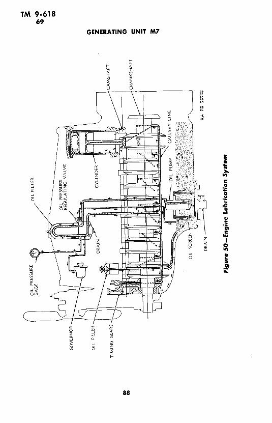
TM 9-61869
GENERATING UNIT M7
>-
5 U
,Js :
DZ "
0
z z
n C][
=u- ,
o , va< ~ ~ ~ ~ ~ ~ o
0 - ZU 0
88

TM 9-61869
ENGINE LUBRICATION SYSTEM
RA PD 56949
Figure 1--Filling Crankcase
Figure 52--0il Level Gage89
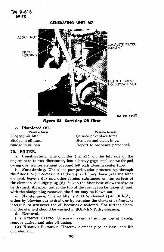
TM 9-61869-70
GENERATING UNIT M7
ACORN NUT
COMPLETE FILTERELEMENT
FI LTERHOUSING
FILTER ELEMENTHOLD-DOWN NUT
RA PD 56951
Figure 53-Servicing Oil Filter
c. Discolored Oil.Possible Cause Possible Remedy
Clogged oil filter. Service or replace filter.Sludge in oil lines. Remove and clean lines.Sludge in oil pan. Report to ordnance personnel.
70. FILTER.a. Construction. The oil filter (fig. 53), on the left side of the
engine next to the distributor, has a heavy-gage steel, dome-shapedcasing over a filter element of round felt pads about a center tube.
b. Functioning. The oil is pumped, under pressure, up throughthe filter tube; it comes out at the top and flows down over the filterelement, leaving dirt and other foreign substances on the surface ofthe element. A sludge plug (fig. 54) in the filter base allows sludge tobe drained. An acorn nut at the top of the casing can be taken off and,with the sludge plug removed, the filter may be blown out.
c. Maintenance. The oil filter should be cleaned (par. 18 b(6))either by blowing out with air, or by scraping the element at frequentintervals, or whenever the oil becomes discolored. For further clean-ing, the element should be washed in SOLVENT, dry-cleaning.
d. Removal.(1) REMOVE CASING. Unscrew hexagonal nut on top of casing,
remove gasket, and take off casing.(2) REMOVE ELEMENT. Unscrew element pipe at base, and lift
out element.
90

TM 9-61870-72
ENGINE LUBRICATION SYSTEM
RA PD 56953
Figure 54-Removing Sludge Plug from Oil Filter Base
e. Installation.(1) INSTALL ELEMENT. Attach element pipe by screwing down
over base nipple.(2) ATTACH CASING. Install cover and secure with nut over gasket.
71. STRAINER.
a. Description. The oil strainer (fig. 57) is of wire mesh on asteel frame attached to a removable cap at the bottom of the crank-case. The oil pump draws the oil through the strainer mesh.
b. Maintenance. The oil strainer should be removed periodically,and cleaned thoroughly with SOLVENT, dry-cleaning. This shouldbe done at least every time the crankcase is drained.
c. Removal.(1) REMOVE CAP (fig. 56). Take out cap screws and lock washers
attaching cap and gasket to crankcase, and lift off oil strainer cap.
d. Installation.(1) INSTALL STRAINER. Place gasket over cap flange, bring cap
into position at the bottom of the crankcase, and install with capscrews and lock washers.
72. OIL PUMP.a. Description. The oil pump is of the submerged-type, gear
91

TM 9-61872
GENERATING UNIT M7
RA PD 56954
Figure 55--0il Pressure Regulating Valve Screw
driven from the camshaft. The pump forces oil from the oil sump atthe bottom of the crankcase to the points to be lubricated.
b. Maintenance. The oil pump requires no maintenance whenworking properly. Repairs are not within the scope of this manual.Oil pressure can be adjusted by the pressure regulating valve (fig. 55)but this may be done only under supervision of higher authority. Toadjust oil pressure proceed as follows:
(1) REMOVE ACORN NUT AND LOOSEN LOCK NUT. Take off acorn
nut and gasket. Loosen lock nut holding adjusting screw.(2) ADJUST VALVE. The adjusting screw should be turned until
the oil pressure gage on the instrument panel registers 25-pound pres-sure at 1,200 rpm. Tightening the screw increases the pressure, loosen-ing the screw decreases pressure. NOTE: The oil pressure should notbe changed or judged to be too high or too low until it is known thatthe proper weight of oil is being used, and the engine is being warmedup to normal operating temperature. As the bearings become worn,more oil will escape around the bearings into the case, lowering thepressure slightly. It is not advisable to try to correct this slight loss ofpressure by an adjustment of the pressure regulator because the extraamount of oil being thrown off by the worn bearings is already over-oiling the cylinder walls.
92

TM 9-61872
ENGINE LUBRICATION SYSTEM
Figure 56-Oil Strainer Cap Removal
RA PD 56956
Figure 57-Oil Strainer Cap Removed93
TM 9-61873
GENERATING UNIT M7
Section XIV
ENGINE ELECTRICAL SYSTEM
Paragraph
Description ........................................ 73
Trouble shooting .................................... 74
Battery ........... ................. ............. 75
Battery-charging generator ........................... : 76
Ignition coil ........................................ 77
Distributor ........................................ 78
Spark plugs ........................................ 79
Starting motor ...................................... 80
73. DESCRIPTION (fig. 58).a. The starting and ignition system consists of a 6-voll: battery
located in a tray bolted to frame cross members on the right-hand sideof the unit, opposite the instrument panel; a battery-charging genera-tor (fig. 61), on the right side of the unit under the manifold; a startingmotor (fig. 71), on the left side of the engine, projecting through thebell housing; a distributor (fig. 66) mounted on a tachometer driveabove the accessory drive; an ignition coil (fig. 65) bolted to the leftside of the engine head, and the spark plugs. On the instrument panelare the ignition switch, the starter switch, and the tachometer head.
h. Functioning.(1) STARTING. The ignition switch on the instrument panel throws
on the 6-volt current in the ignition line. The starter switch on thepanel makes the connection to the starting motor which turns overthe engine.
(2) IGNITION. The battery circuit furnishes the electnc spark thatignites the mixture in the cylinders. The ignition switch connects thebattery line to the ignition coil, which transforms the 6-volt current tothe high voltage required to produce the hot spark necessary for cylin-der ignition. The distributor makes the succession of momenrtary con-tacts that pass the high-voltage current to the spark plugs in the properfiring order.
(3) LIGHTING. The battery line provides an auxiliary lighting cir-cuit for use when the generator is not functioning. A 6-volt pilot lightis located on the instrument panel, and a 6-volt receptacle is also pro-vided there to receive the 6-volt trouble light carried in the tool box.
94

TM 9-61874-75
ENGINE ELECTRICAL SYSTEM
74. TROUBLE SHOOTING.a. Engine Fails to Start-Ammeter Showing Pulsating Dis-
charge.Possible Cause Possible Remedy
No spark. Replace coil-distributor wire.Weak spark. Clean and adjust distributor
points, or replace condenser.Weak spark after replacing con- Replace coil.
denser.Distributor cap cracked. Replace distributor cap.Grounded distributor rotor. Replace rotor.Defective spark plug cable. Replace cable.Defective spark plugs. Service or replace.
b. Ammeter Indicates Constant Normal Discharge when En.gine Is Being Cranked.Faulty distributor. Report to ordnance personnel.Defective or grounded coil-dis- Eliminate ground or replace
tributor wire. wire.Defective coil. Replace coil.
c. Ammeter Shows No Discharge.Distributor faulty. Report to ordnance personnel.Defective wire, shorted connec- Eliminate ground, or replace de-
tion, etc.' fective wire.
d. Engine Fails To Crank.Fully discharged battery. Charge battery.Starting motor burned out. Replace motor.Starting switch faulty. Replace switch.Loose connections. Tighten connections.Corroded battery terminals. Replace terminals.
75. BATTERY (figs. 59 and 60).a. Description. The battery is located on the right-hand side of
the unit, opposite the instrument panel, alongside the center uprightof the housing, to which its negative terminal is grounded. The posi-tive terminal is connected to the starter button. Battery capacity is160 ampere-hours at 20-hour rate.
b. Trouble Shooting.(1) BATTERY DOES NOT FUNCTION.
Possible Cause Possible Remedy
Battery discharged. Charge battery.Battery connections corroded. Clean with file and wire brush
and coat with GREASE, gen-eral purpose (seasonal grade).
Battery will not charge. Replace.95

TM 9-61875
GENERATING UNIT M7
O
oTT
I-
o_
I-
F- >p Z 0} _ i ·.
CCe z F a
I >0 9. o
'v~~~o F^
. e
Ip I ~O--
a O)~~~~~
I - ~ -'I--
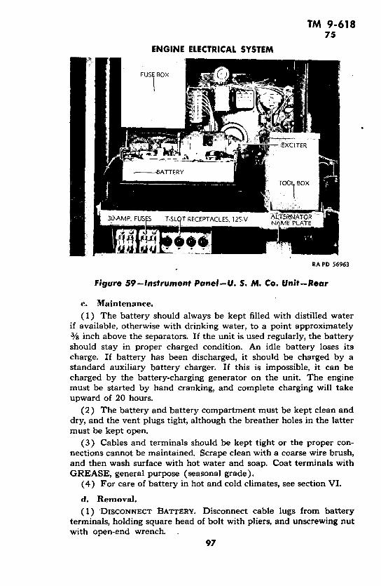
TM 9-61875
ENGINE ELECTRICAL SYSTEM
_ 8ATXCITER
----- BATTERY
_ FUSFS T-SLQT RECEPTACLE5, 125-V
RA PD 56963
Figure 59-instrument Panel-U. S. M. Co. Unit-Rear
c. Maintenance.
(1) The battery should always be kept filled with distilled waterif available, otherwise with drinking water, to a point approximately3/8 inch above the separators. If the unit is used regularly, the batteryshould stay in proper charged condition. An idle battery loses itscharge. If battery has been discharged, it should be charged by astandard auxiliary battery charger. If this is impossible, it can becharged by the battery-charging generator on the unit. The enginemust be started by hand cranking, and complete charging will takeupward of 20 hours.
(2) The battery and battery compartment must be kept clean anddry, and the vent plugs tight, although the breather holes in the lattermust be kept open.
(3) Cables and terminals should be kept tight or the proper con-nections cannot be maintained. Scrape clean with a coarse wire brush,and then wash surface with hot water and soap. Coat terminals withGREASE, general purpose (seasonal grade).
(4) For care of battery in hot and cold climates, see section VI.
d. Removal.
(1) DISCONNECT BATTERY. Disconnect cable lugs from batteryterminals, holding square head of bolt with pliers, and unscrewing nutwith open-end wrench.
97
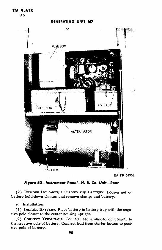
TM 9-61875
GENERATING UNIT M7
| 'nFUSlE BOX a
RA PD 56965
Figure 60--Instrument Panel-H. B. Co. Unit--Rear
(2) REMOVE HOLD-DOWN CLAMPS AND BATTERY. Loosen nut onbattery hold-down clamps, and remove clamps and battery.
e. Installation.(1) INSTALL BATTERY. Place battery in battery tray with the nega-
tive pole closest to the center housing upright.(2) CONNECT TERMINALS. Connect lead grounded on upright to
the negative pole of battery. Connect lead from starter button to posi-tive pole of battery.
98

TM 9-61875-76
ENGINE ELECTRICAL SYSTEM
Figure 61 -Battery-Charging Generator
(3) INSTALL HOLD-DOWN CLAMPS. Adjust hold-down clamps ateach end of battery, and fasten nuts and lock washers to hold clampssecurely.
76. BATTERY-CHARGING GENERATOR (fig. 61).a. Construction. The battery-charging generator is a 2-pole,
shunt-wound, third-brush regulated, ventilated unit with a capacity of6 volts. A 2-charge voltage regulator is mounted on the generatorframe, and combines the cut-out with the regulator. A 5-ampere fuse(fig. 64) is mounted in the regulator.
b. Functioning. The generator produces current for charging thebattery. The regulator allows the generator to charge at its high rateuntil the battery is nearly charged, and has reached a predeterminedvoltage, at which time a resistance is cut into the field circuit of thegenerator, reducing the charging rate approximately one-half. The cut-out acts as an automatic switch between the generator and the battery,closing the circuit when the generator is producing sufficient output tocharge the battery, and opening the circuit when the generator is notcharging, so as to prevent the battery from discharging back throughthe generator.
THE ARMY Lill"ri~ 1 WA._INGTON, D.J
TM 9-61876
GENERATING UNIT M7
c. Trouble Shooting.(1) BURNT-OUT FUSE.
Possible Cause Possible Remedy
Stuck relay creates short from Replace relay and fuse.overcharging.
(2) GENERATOR FAILS TO CHARGE.
Brushes burned out or worn out. Replace brushes.
(3) Low CURRENT OR No CURRENT.
Open circuit in brush connec- Replace brushes.tions.
Brush sticks in holder. Loosen and place on cornmuta-tor.
Open circuit due to dirty corn- Clean commutator.mutator.
(4) NOISE AT ENGINE IDLING SPEED.
Noisy bearing. Notify ordnance personnel.Loose pulley. Tighten pulley.Loose pole piece. Tighten pole piece.
d. Maintenance.
(1) To inspect the battery-charging generator, remove the cover atthe commutator end. If the commutator is discolored or dirty, it canbe polished by holding a piece of PAPER, flint, class B, grade No. 2/0,against it while the generator is running slowly.
(2) BRUSHES.(a) If brushes are badly worn, new brushes should be installed.
The brushes should be fitted to have at least 80 percent brush surfacecontact with the commutator. To seat the brushes, clean the commu-tator (step (1), above), then wrap around the commutator a piece ofPAPER, flint, class B, grade No. 2/0, of the same width as the com-mutator, and move it back and forth along the commutator withsanded face against brushes. Turn the commutator clockwise fromdrive end until brushes seat properly. Blow the generator out withcompressed air to remove all particles of abrasive. Use only PAPER,flint, class B, grade 40, to seat brushes.
(b) Brush spring tension can be tested by hooking a scale in thehole at the end of the brush arm, and taking a reading as the armleaves the brush. The tension for all three brushes, when new, shouldnot be more than 53 ounces maximum.
(c) The charging rate of the generator is controlled by a thirdbrush that is adjustable. Advance or retard the third brush as required.Moving the brush in direction of rotation increases the charging rate,while moving it against armature rotation decreases the charging rate.
(3) BATTERY-CHARGING GENERATOR BRUSH REPLACEMENT.(a). Remove Cover Strip. Unscrew bolt holding cover strip in place,
and remove strip.
100

TM 9-61876
ENGINE ELECTRICAL SYSTEM
Figure 62-Loosening Battery-Charging Generator Holding Screw
j~~~~/7~~~~~~~~~~~~~ /
Figure 63-Battery-Charging Generator Guard Removal101

TM 9-61876
GENERATING UNIT M7
Figure 64-Voltage Regulator Fuse
(b) Remove Brushes and Replace. Take out screws attaching brushleads. Hold back spring clips and remove brushes. Put new b)rushesin position under clips, attach leads, and replace cover strip.
e. Removal.(1) REMOVE GUARD PLATE (fig. 47). Loosen lock nut on holding
cap screw (fig. 62) that goes through generator housing to secure gen-erator in place. Loosen cap screw., Turn generator until the regulatoris at the front, and the cap screws holding the metal guard are acces-sible. Remove cap screws attaching guard to cylinder chamber coverplate and the engine.
(2) REMOVE GENERATOR. Take out screw that holds lead to the2-charge regulator. The loosened generator will now be removed.
f. Installation.(1) INSERT GENERATOR IN HOUSING AND CONNECT LEAD. Place
generator in position in housing, and connect lead.(2) ATTACH GUARD. Place cylinder compartment cover plate in
position, and attach guard plate by cap screws through guard andcover plate.
(3) SECURE GENERATOR IN PLACE. Turn generator in housing untilthe 2-charge regulator is at the top, under the guard. Tighten holdingcap screw and secure with lock nut.
102
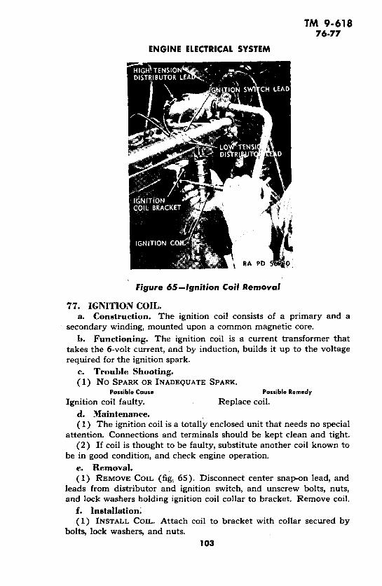
TM 9-61876-77
ENGINE ELECTRICAL SYSTEM
Figure 65-Ignition Coil Removal
77. IGNITION COIL.a. Construction. The ignition coil consists of a primary and a
secondary winding, mounted upon a common magnetic core.
b. Functioning. The ignition coil is a current transformer thattakes the 6-volt current, and by induction, builds it up to the voltagerequired for the ignition spark.
c. Trouble Shooting.(1) No SPARK OR INADEQUATE SPARK.
Possible Cause Possible Remedy
Ignition coil faulty. Replace coil.
d. Maintenance.(1) The ignition coil is a totally enclosed unit that needs no special
attention. Connections and terminals should be kept clean and tight.(2) If coil is thought to be faulty, substitute another coil known to
be in good condition, and check engine operation.
e. Removal.(1) REMOVE COIL (fig: 65). Disconnect center snap-on lead, and
leads from distributor and ignition switch, and unscrew bolts, nuts,and lock washers holding ignition coil collar to bracket. Remove coil.
f. Installation.(1) INSTALL COIL. Attach coil to bracket with collar secured by
bolts, lock washers, and nuts.
103

TM 9-61877
GENERATING UNIT M7
la P
w < 0 L
o < uU
0 Ln ! | n l l I _ n QI o a *
0 p _ Du S <t0 a
= Z.0 . IU <1 \ ~ < <-0o, ' 0-
a~ L U < p 62- U o0 -i M 0
Lu CD o
~~e ad
10
TM 9-61877-78
ENGINE ELECTRICAL SYSTEM
(2) CONNECT LEADS. Attach center snap-on lead and side leadsfrom distributor and ignition switch.
78. DISTRIBUTOR (fig. 66).a. Construction. The distributor is a 6-cylinder, automatic, single
breaker arm type which contains the battery circuit contact points,automatic advance mechanism, and high-tension distributor. A con-denser is set across the lines.
h. Functioning. The rotor makes contact between the spark plugconnected points in the cover and the ignition coil line. The breakerinterrupts the current in the primary line of the ignition coil, whichinduces high-tension current in the secondary. The condenser cush-ions the shock of the interrupted current, and prevents burning of thebreaker points.
c. Trouble Shooting.(1) ENGINE WILL NOT START.
Possible Cause Possible RemedyBreaker points defective. Replace points.Breaker arm grounded. Replace arm.Defective cap. Replace cap.Defective rotor. Replace rotor.
(2) POOR STARTING OR ENGINE MISSING.Breaker points carbonized. Clean breaker points.Breaker points gummy. Clean breaker points.Breaker points badly worn or Resurface, or install new breaker
pitted. arm and points.(3) ENGINE "PINGING" OR BACKFIRING THROUGH CARBURETOR.
Distributor too far advanced. Report to ordnance personnel.(4) ENGINE HESITATES IN STARTING, BACKFIRES THROUGH Ex-
HAUST, OR EXHAUST MANIFOLD GETS EXCESSIVELY HOT.
Distributor too far retarded. Report to ordnance personnel.(5) DISTRIBUTOR CAP SPARKS FROM LEADS TO SPARK PLUGS.
Cracked distributor cap. Replace cap.(6) ENGINE MISSES AT Low SPEED.
Breaker point gap too small. Adjust gap.(7) ENGINE MISSES AT HIGH SPEED UNDER LOAD.
Breaker point gap too large. Adjust gap.Breaker arm spring tension too Replace arm.
weak.(8) ENGINE MISSES AT ALL SPEEDS.
Breaker contact points too far Adjust.apart.
Breaker contact points pitted. Replace breaker arm and screwpoint.
Breaker point screw loose. Tighten screw.
105

TM 9-61878
GENERATING UNIT M7
Figure 67-Distributor-Cap Removed
d. Maintenance.
(1) DISTRIBUTOR CAP. The distributor cap (fig. 67) must be keptclean and should be constantly inspected for cracks, carbon runners,evidence of arcing, or corroded high-tension terminals. If any of theseconditions are present, the cap should be replaced. After a distributorcap has had normal use, the inside of the cap inserts will becomeslightly burned. If these inserts are badly burned at any other point,the cap should be replaced.
(2) ROTOR. The rotor should be inspected for cracks. I:f cracksare found, it should be replaced. After a rotor has had normal use,the end of the contact will become burned. If this burning is notexcessive, and is found only on the end of the metal strip, the rotorneed not be replaced. If burning is found on the top of the strip, itindicates the rotor is too short, and needs replacing. Usually whenthis condition is found, the distributor cap inserts will be burned ontheir horizontal face, and the cap also will need replacing.
(3) BREAKER POINTS. If breaker points are in good condition, theywill show a grayish color with no evidence of burning or pitting.Breaker points should be so alined as to make contact over the wholearea of the contact surfaces. Breaker point gap should be 0.020 inch±0.002 inch. If alinement is not correct, bend the stationary pointbracket to secure proper alinement, and then adjust the gap 1fig. 68),
106
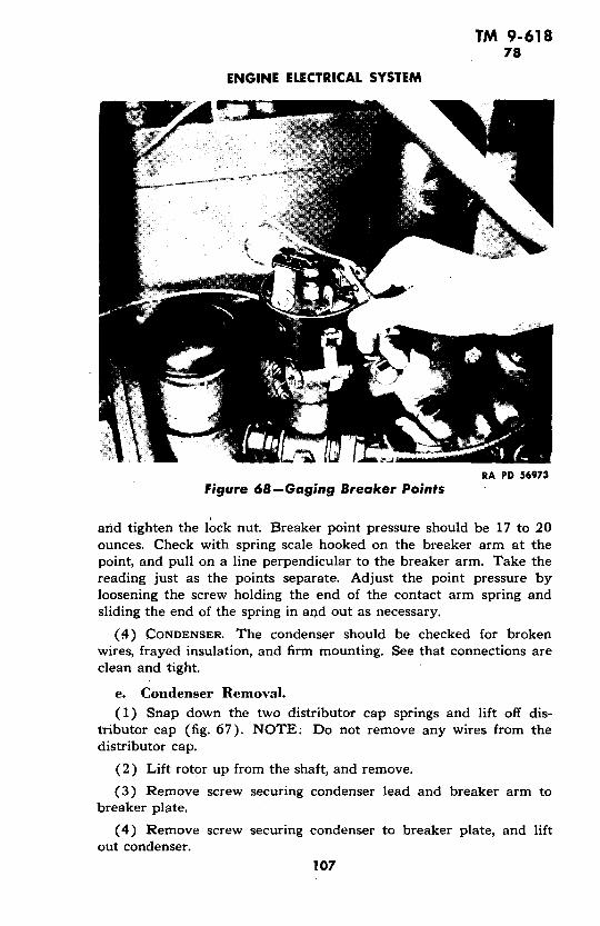
TM 9-61878
ENGINE ELECTRICAL SYSTEM
RA PD 56973Figure 68-Gaging Breaker Points
atd tighten the lock nut. Breaker point pressure should be 17 to 20ounces. Check with spring scale hooked on the breaker arm at thepoint, and pull on a line perpendicular to the breaker arm. Take thereading just as the points separate. Adjust the point pressure byloosening the screw holding the end of the contact arm spring andsliding the end of the spring in and out as necessary.
(4) CONDENSER. The condenser should be checked for brokenwires, frayed insulation, and firm mounting. See that connections areclean and tight.
e. Condenser Removal.
(1) Snap down the two distributor cap springs and lift off dis-tributor.cap (fig. 67). NOTE: Do not remove any wires from thedistributor cap.
(2) Lift rotor up from the shaft, and remove.
(3) Remove screw securing condenser lead and breaker arm tobreaker plate.
(4) Remove screw securing condenser to breaker plate, and liftout condenser.
107

TM 9-61878
.GENERATING UNIT M7
RA PD 56907
Figure 69-Spark Plug Removal
R GAGE
RA PD 56905Figure 70-Gaging Spark Plug Gap
108
TM 9-61878-79
ENGINE ELECTRICAL SYSTEM
f. Condenser Installation.(1) Place condenser in position on breaker plate in distributor,
and secure with machine screw.(2) Connect condenser lead to breaker plate terminal with screw
securing breaker arm to breaker plate terminal.(3) Place rotor in position over distributor shaft. Distributor shaft
is cut so that it is possible to put rotor on shaft in one position. Checkposition rotor is to be inserted to avoid breaking rotor.
(4) Place distributor cap on distributor, and secure in positionwith the two distributor cap springs.
79. SPARK PLUGS.a. Description. The spark plugs are of the commercial automo-
tive type with electrode gap adjustments made by bending the sideelectrode. Each plug consists of a metal shell within which is fixed aninsulator with a central electrode stem. The metal shell is threaded toscrew into the engine cylinder head. The central electrode stem isthreaded at the upper part of the insulator to provide means of attach-ing the high tension lead from the distributor. Champion No. I com-mon, or equivalent spark plugs are used. These plugs are a cold-type,and under no circumstances should they be replaced with hot-typeplugs.
h. Functioning. When the circuit from the ignition coil to thespark plug is closed, a spark jumps across the spark plug electrode gapand ignites the gas mixture in the combustion chamber.
c. Trouble Shooting. Cracked, dirty, or improperly adjustedspark plugs cause poor engine performance. To determine if faultyengine performance is caused by one or more faulty spark plugs, start:engine and set speed slightly above idling. Short out each spark plugwith a wood-handle screwdriver, by holding the screwdriver bit against:the spark plug terminal and engine cylinder head. NOTE: Do nottouch metal part of screwdriver as an unpleasant shock will be felt.If there is noticeable difference in the engine performance, the shortedspark plug can be assumed to be in good condition. If, however, thereis no noticeable difference in engine performance, the shorted sparkplug should be renewed. If the installation of new spark plugs does notimprove engine performance, fault must be found elsewhere in theignition system, in the fuel system, or a mechanical defect exists in theengine.
d. Maintenance. Remove spark plugs after each 100 hours ofoperation, and make the following check.
(1) Check for cracked or blistered insulations, and replace plugs ifany is evident.
(2) Check for dirty electrodes and insulations. Thoroughly cleaneach dirty spark plug in sand blast spark plug cleaner.
109

TM 9-61879-80
GENERATING UNIT M7
(3) Check for worn electrodes. Replace spark plugs wil:h wornelectrodes.
(4) Check and adjust spark plug electrode gap using 0.025 feeleron gage (fig. 70). Bend outside electrode with pliers to obtain correctgap. Never bend inside electrode.
(5) Test each spark plug on a spark plug tester to assure properperformance.
e. Removal. Unsnap high tension lead from the spa:rk plugterminal, and using a spark plug wrench (fig. 69)., unscrew spark plugfrom cylinder head. Lift off spark plug gasket with spark plug.
f. Installation. Place copper gasket over threaded portion of thespark plug shell, and screw spark plug into cylinder using spark plugwrench. Avoid excessive pressure when tightening spark plugs. Attachproper high tension lead to spark plug terminal.
80. STARTING MOTOR.a. Construction. The starting or cranking. motor is a heavy-duty
4-brush, Bendix drive type. It is located at the lower left side of theengine, and secured to the engine bell housing. The right-hand out-board Bendix drive transmits power to the engine flywheel ring gear(fig. 72). A removable head band gives access to commutator andbrushes.
b. Functioning. As the motor starts, the Bendix gear moves intomesh with the flywheel ring gear, and rotates the engine flywheel andcrankshaft. As soon as the engine starts to run, the Bendix gear re-tracts until it is out of mesh with the flywheel ring gear.
c. Trouble Shooting.(1) FAILS TO OPERATE.
Possible Cause Possible RemedyBattery discharged. Recharge battery.Loose or dirty connections. Clean and tighten connections.Bendix gear jammed. Free gear from flywheel.Starting motor switch faulty. Replace switch.Bendix drive at fault. Repair starter.
(2) STARTING MOTOR CRANKS WEAKLY.Battery weak. Recharge battery.Loose or dirty connections. Clean and tighten connections.Commutator dirty. Remove band and clean com-
mutator with PAPER, flint,class B, No. 2/0.
Starting motor faulty. Replace.(3) BENDIX DRIVE FAILS TO OPERATE WHEN STARTING MOTOR
REVOLVES.Dirty or gummy Bendix drive. Remove starting motor. Clean
and lubricate drive.110

TM 9-61880
ENGINE ELECTRICAL SYSTEM
RA PD 84573
Figure 71-Starting Motor Removal
RA PD 56970
Figure 72-Starting Motor Drive and Flywheel111
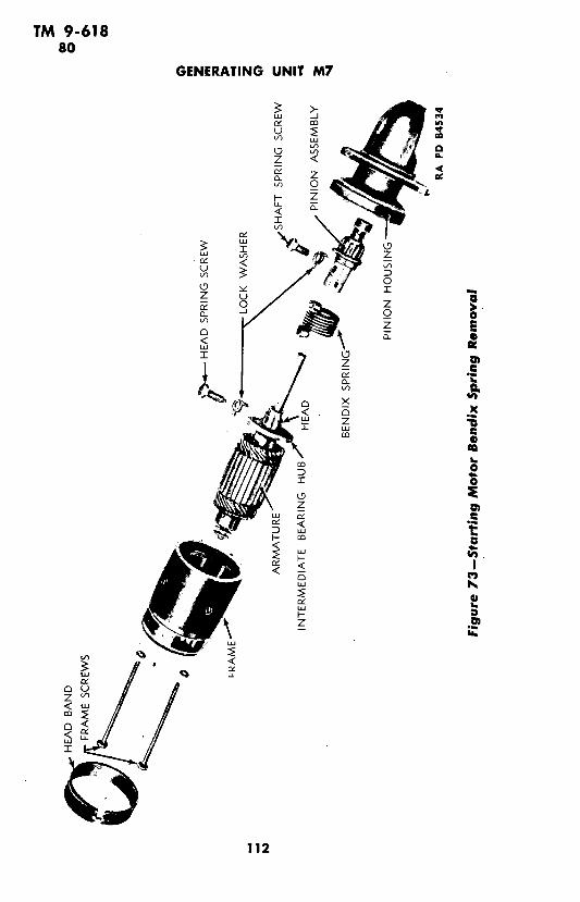
TM 9-61880
GENERATING UNIT M7
z <z
° E + 0
- st E
- T
,i.
LUXr~~~~~~~r
IC3 I~~~~~,0n O O
z12
'I-

TM 9-61880
ENGINE ELECTRICAL SYSTEM
d. Maintenance.(1) The cover band should be removed periodically, and the
brushes and commutator inspected. If brushes wear excessively, checkfor excessive brush spring tension and for roughness or high mica ofthe commutator. Check for loose flange mounting screws and oilseepage into the drive from the engine bell housing.
(2) STARTING MOTOR BRUSH REPLACEMENT.(a) Remove Head Band.(b) Remove Brushes and Replace. Take out screws holding brush
leads. Hold back clips, and remove brushes. Put new brushes in posi-tion under clips, and attach leads.
(c) Replace Head Band. Place head band back in position, andsecure with holding bolt, lock washer, and nut.
e. Removal (fig. 71).(1) DISCONNECT LEAD. Remove nut attaching starter switch lead
to post on the frame of the starting motor.(2) REMOVE MOTOR. Take out three cap screws and lock washers
holding motor to front of bell housing and lift off starting motor.f. Installation.(1) INSTALL STARTING MOTOR. Place motor in position on front
of bell housing, securing it with the three cap screws and lock washers.(2) ATTACH STARTER LEAD. Bring lead from starter switch to post
on frame of starting motor, and attach with nut provided.g. Bendix Spring Removal (fig. 73).(1) Remove starting motor (step e, above).(2) Loosen head band clamp screw, and remove commutator end
head band.(3) Remove the two frame screws, and pull pinion housing and
armature from starting motor frame. Do not separate commutator endhead from frame.
(4) Slide pinion housing from armature shaft.(5) Bend down the lip on each lock washer, and remove head
spring screw and shaft spring screw.(6) Slide pinion assembly off armature shaft, and lift off Bendix
spring.h. Bendix Spring Installation (fig. 73).(1) Thoroughly clean Bendix drive parts in SOLVENT, dry-clean-
ing, and apply a few drops of OIL, engine, SAE 10 to armature shaft,pinion shaft, and armature shaft bearings.
(2) Slide Bendix spring and pinion assembly in position overarmature shaft. Using a lock washer (special) over each screw, securespring to head and armature shaft, using head spring screw (doweled).NOTE: Doweled portion of head spring screw must enter hole in
-armature shaft. Secure spring to pinion assembly using shaft springscrew. Lock screws by bending up the lip on each lock washer.
113

TM 9-61880-81
GENERATING UNIT M7
(3) Assemble armature shaft with attached Bendix drive assemblyinto pinion housing, so that intermediate bearing hub slot lines upwith the dowel in housing. Push hub into position on housing. Rotatearmature to test if the armature bearings are lined up. The armatureshould rotate freely.
(4) Lift up on the four brushes, and, with thrust washers overshaft on commutator end of armature, push armature through startingmotor frame, so that shaft enters end head bearing. Release brushes.
(5) Attach commutator end head and pinion housing t:o frame,using the two frame screws.
(6) Place head band over commutator end head, and secure inposition with clamp screw.
(7) Install starting motor (step f, above).
Section XV
GENERATING SYSTEMParagraph
Description ......................................... 81Trouble shooting ............................ ......... 82Alternator description ................................. 83Alternator trouble shooting ............................ 84Alternator maintenance .............................. 85Exciter description ................................... 86Exciter trouble shooting ......... ..................... 87Exciter maintenance ................................. 88200-ampere power receptacle .................. ... .. 8930-ampere power receptacle ........................... 90
81. DESCRIPTION (fig. 74).a. Construction. The generating system is made up of the alter-
nator, the exciter, a rheostat on the exciter line, a load switch, anammeter for registering the amperage of the current delivered, a volt-meter for registering the voltage, a meter switch to connect each ofthe phases of the circuit with the ammeter and voltmeter, two lightsockets, a toggle switch with a lamp-dimming rheostat to controlthem, two power receptacles, T-slot receptacles, and fuses.
b. Functioning. The engine, directly coupled to the alternatorshaft, turns the alternator rotor and (through a V-belt) the exciterarmature, or by direct connection on the alternator shaft in the caseof the H. B. Co. unit. The exciter supplies the alternator field current
114

TM 9-61881-82
GENERATING SYSTEM
as required by the load. The exciter field rheostat may be used tomaintain'constant alternator output voltage under varying loads. Theload switch completes or interrupts the load circuit from the alternatorto the two power receptacles. Five T-slot receptacles and two lampsockets are fed from the line ahead of the load switch. The lamps arecontrolled by a toggle switch, and the illumination given is controlledby a dimming rheostat.
82. TROUBLE SHOOTING.a. Failure to Build up Voltage.
Possible Cause Possible Remedy
Loose connections. Check, and tighten all connec-tions.
Reversed field connections. Interchange connections "F1"and "F2" at terminal block.
Absence of residual magnetism. Lift alternator brushes for a fewmoments while it is running.If voltage does not then buildup, excite field for a momentin proper direction with ex-citer brush raised, using anoutside source such as a bat-tery.
Reversed polarity. Same as above.Collector ring brushes not mak- Increase spring pressure, and
ing proper contact. clean brush holders.Exciter belt slipping. Tighten belt.Burnt-out exciter windings. Report to ordnance personnel.Burnt-out alternator windings. Report to ordnance personnel.Open circuit in field rheostat. Report to ordnance personnel.
b. Excessive Sparking at Exciter Brushes.Dirty or pitted commutator. Clean or dress commutator.
c. Excessive Sparking at Slip Rings.Dirty or pitted slip rings. Clean or dress slip rmings.
d. Excessive Heating of Alternator.Overload. Decrease load to allowable limit.Grounded or open stator coils. Report to ordnance personnel.
e. Excessive Heating of Exciter.Open circuit in armature coil. Report to ordnance personnel.Grounded commutator. Report to ordnance personnel.
f. Excessive Noise in Alternator.Broken bearings. Report to ordnance personnel.Coupling failure. Report to ordnance personnel.Worn-out brushes. Replace brushes.Damaged brush springs. Replace springs.
115

TM 9-61882
GENERATING UNIT M7
-i
6 ram
OU W O
<
Ln I>t - n
0 o, Xi]
UJ 0
L <U
*L_ L_
Lu
Jv, ',.
Ln I 1
< u o0 wD
CCY
I I
L q
LU
H
116
mN ~ J

TM 9-61882-84
GENERATING SYSTEM
g. Excessive Noise in Exciter.Possible Cause Possible Remedy
Broken bearings. Report to ordnance personnel.Commutator damaged. Report to ordnance personnel.Improperly fitted brushes. Fit brushes properly.Worn-out brushes. Replace brushes.Damaged brush springs. Replace springs.
83. ALTERNATOR DESCRIPTION.a. Construction. The alternator is an electric a-c generator con-
nected to the engine by means of a flexible coupling. It is semipro-tected type and is self-ventilated.
b. Functioning. The alternator, in combination with the exciter,takes the mechanical energy of the engine and transforms it into elec-trical energy by magnetic induction. When driven at its rated speed,the alternator, with its field energized by the exciter, produces a volt-age at its terminals equivalent to that provided by the usual 125-voltlighting circuit. This voltage can'be varied over a range of 90 to 150volts by the use of the field rheostat.
84. ALTERNATOR TROUBLE SHOOTING.a. Failure to Build up Voltage.
Possible Cause Possible RemedyLoose connections. Check and tighten all connec-
tions.Absence of residual magnetism. Lift alternator brushes for a few
moments while it is running.If voltage does not then buildup, excite field for a. momentin proper direction with ex-citer brush raised, using anoutside source, such as a bat-tery.
Reversed polarity. Same as above.Collector ring brushes not mak- Increase spring pressure, and
ing proper contact. clean brush holders.Damaged brush springs. Replace springs.Burnt-out windings. Report to ordnance personnel.Worn-out brushes. Replace brushes.
b. Excessive Sparking at Slip Rings.Dirty or pitted slip rings. Clean or dress slip rings.
c. Excessive Heating.Overload. Decrease load to allowable limit.Grounded or open stator coils. Report to ordnance personnel.
117

TM 9-61884
GENERATING UNIT M7
RA PID 56983
Figure 75-Alternator-Showing Springs, Brushes andBrush Holders
PIGTAIL CONNECTION
BRUSH
ARM AND SPRING
RA PD 56985 _ ~ a "
Figure 76-H. B. Co. Unit-View Through Exciter and AlternatorBrush Holder Ring
118
TM 9-61884-85
GENERATING SYSTEM
d. Excessive Noise.Possible Cause Possible Remedy
Broken bearings. Report to ordnance personnel.Loose or damaged brush springs. Tighten or replace brush springs.Coupling failure. Report to ordnance personnel.Worn or improperly fitting Fit brushes properly, or replace.
brushes.
85. ALTERNATOR MAINTENANCE.a. Brush Inspection. Alternator brushes (fig. 75) should be in-
spected at least every 3 months. If gummy and stuck in brush holders,they should.be removed and cleaned. All brush holder supports shouldalso be cleaned. Screws holding pigtail connections should be tight.Brush holder box should not be less than %0 inch nor more thanl/s inch from collector rings.
b. Brush Removal. Loosen screw holding pigtail connection,and slide connection lug out from under screw. Lift brush spring frombrush, and remove brush.
c. Brush Installation. Slide pigtail connection lug under screw,and tighten screw. Place brush in holder, and set spring on top to keepbrush tight against collector ring.
d. Brush Spring Inspection. Brush springs are designed to givea minimum pressure of 8 ounces per brush. This pressure is not crit-ical on collector rings, and spring pressure will be maintained indefi-nitely unless brush pigtail circuit opens and brush spring carriesexciting current. If so, it will lose its temper, and should be replaced.To check brush spring pressure, hook spring scale under at point whereit bears on brush, and pull in direction of brush travel in brush holder,until finger is just lifted off brush.
e. Brush Spring Removal (Units Other than H. B. Co.). Pryapart the jaws of the spring-holding clamp, and remove spring.
f. Brush Spring Installation (Units Other than H. B. Co.).Pry apart the jaws of the spring-holding clamp and slide the spring in.Place the free end of the spring on top of the brush.
g. Brush Spring Removal (H. B8. Co. Unit) (fig. 76).(1) REMOVE COVER. Take out machine screws, nuts, and lock
washers holding louvered, sheet metal cover on exciter bearing bracket.(2) REMOVE SPRING HOLDER ASSEMBLY. Hold nut, and remove
bolt, washer, tension arm sleeve, spring adjusting washer, and spring.h. Brush Spring Installation (H. B. Co. Unit). Assemble bolt
and washer through tension arm sleeve. Set spring adjusting washerover spring. Carry bolt through brush holding flange, hold nut. andtighten bolt.
i. Collector Ring Inspection. Collector rings should be inspectedperiodically to see if they are smooth and glossy. Use of extremelyhard brushes, presence of grit or other abrasive material which may
119
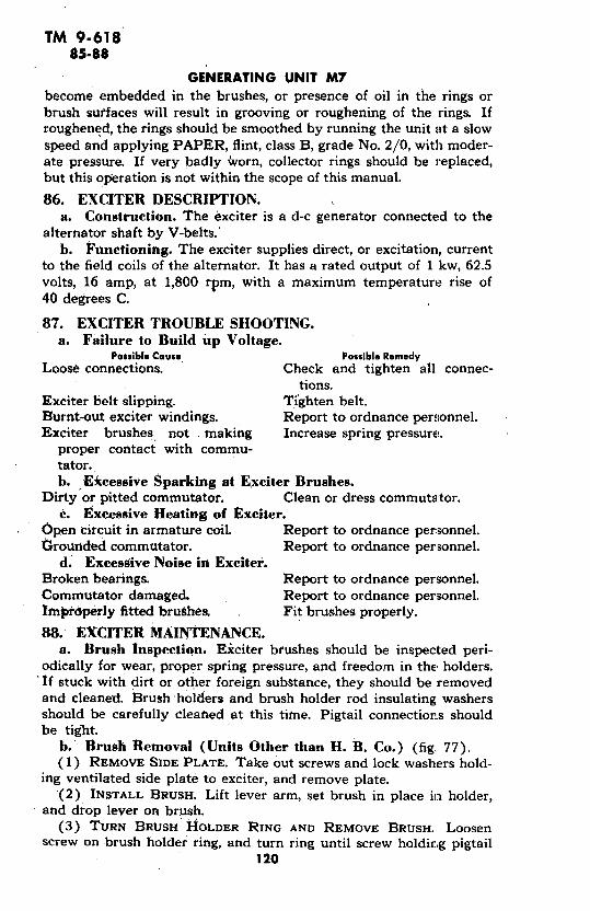
TM 9-61885-88
GENERATING UNIT M7become embedded in the brushes, or presence of oil in the rings orbrush surfaces will result in grooving or roughening of the rings. Ifroughened, the rings should be smoothed by running the unit at a slowspeed and applying PAPER, flint, class B, grade No. 2/0, with moder-ate pressure. If very badly worn, collector rings should be replaced,but this operation is not within the scope of this manual.
86. EXCITER DESCRIPTION.a. Construction. The exciter is a d-c generator connected to the
alternator shaft by V-belts.'b. Functioning. The exciter supplies direct, or excitation, current
to the field coils of the alternator. It has a rated output of 1 kw, 62.5volts, 16 amp, at 1,800 rpm, with a maximum temperature rise of40 degrees C.
87. EXCITER TROUBLE SHOOTING.a. Failure to Build up Voltage.
Possible Cause Possible RemedyLoose connections. Check and tighten all connec-
tions.Exciter belt slipping. Tighten belt.Burnt-out exciter windings. Report to ordnance personnel.Exciter brushes not making Increase spring pressure.
proper contact with commu-tator.b. Excessive Sparking at Exciter Brushes.
Dirty or pitted commutator. Clean or dress commutator.c. Excessive Heating of Exciter.
Open circuit in armature coil. Report to ordnance personnel.Grounded commutator. Report to ordnance personnel.
d. Excessive Noise in Exciter.Broken bearings. Report to ordnance personnel.Commutator damaged. Report to ordnance personnel.Irnmpiperly fitted brushes. Fit brushes properly.
88. EXCITER MAINTENANCE.a. Brush Inspection. Eiciter brushes should be inspected peri-
odically for wear, proper spring pressure, and freedom in the holders.'If stuck with dirt or other foreign substance, they should be removedand cleaned. Brush:holders and brush holder rod insulating washersshould be carefully cleaned at this time. Pigtail connections shouldbe tight.
b.' Brush Removal (Units Other than H. B. Co.) (fig. 77).(1) REMOVE SIDE PLATE. Take out screws and lock washers hold-
ing ventilated side plate to exciter, and remove plate.(2) INSTALL BRUSH. Lift lever arm, set brush in place in holder,
and drop lever on brush.(3) TURN BRUSH I4OLDER RING AND REMOVE BRUSH. Loosen
screw on brush holder ring, and turn ring until screw holding pigtail120

TM 9-61888
GENERATING SYSTEM
connection is accessible. Remove screw, hold back spring lever arm,and take out brush.
c. Brush Installation (Units Other than H. B. Co.).(1) CONNECT BRUSH LEAD. Attach pigtail to screw above brush
holder bolt.(2) INSTALL BRUSH. Lift lever arm, set brush in place in holder,
and drop lever on brush.(3) TURN RING AND ATTACH SIDE PLATE.' Turn brush holder ring
until line on ring coincides with casting rib. Attach plate with screwsand lock washers.
d. Brush Removal (H. B. Co. Unit).(1) REMOVE EXCITER BEARING BRACKET COVER. Remove machine
screws, nuts, and lock washers holding louvered, sheet metal cover onexciter bearing bracket.
(2) DISCONNECT PIGTAIL CONNECTION. Loosen copnecti6n screwon bracket holding brush to commutator, and slide out pigtail connec-tion lug.
(3) REMOVE BRUSH. Lift brush holder arm, and remove brush.
e. Brush Installation (H. B. Co. Unit).(1) INSTALL PIGTAIL CONNECTION. Slide brush pigtail connection
lug under connection screw on brush holder bracket. Tighten screw.(2) INSTALL BRUSH. Lift brush holder arm, slide -in brush, and
drop arm to hold brush securely in place.(3) INSTALL COVER. Place cover in position. securing with screws,
lock washers, and nuts.
f. Brush Springs. Brush springs are designed to give a normalpressure of 12 to 14 ounces per brush. To check brush spring pressure,hook spring scale under spring at point where it bears on brush, andpull in direction of brush travel in brush holder, until finger is justlifted off brush.
g. Brush Spring Removal (Units Other than H. B. Co.).(1) REMOVE SIDE PLATE. Take out screws and lock washers hold-
ing ventilating side plate to exciter.(2) TURN BRUSH HOLDER RING. Loosen screw holding brush
holder ring in position, and turn until brush holder bolt is accessible.(3) REMOVE BRUSH HOLDER BOLT FROM RING. Loosen the three
nuts on the brush holder bolt, and remove bolt and brush holderassembly from yoke of brush holder ring.
(4) REMOVE SPRING. Take out the round-head brass screw hold-ing together the spring, the tension lever arm, a brass sleeve, and thebrush holder arm.
h. Brush Spring Installation (Units Other than H. B. Co.).(1) INSTALL SPRING HOLDING ASSEMBLY ON BRUSH HOLDER
BOLT. Slip round-head brass screw through hole in ratchet, and as-121
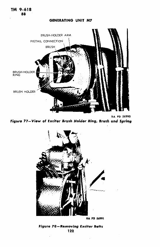
TM 9-61888
GENERATING UNIT M7
BRUSH-HOLDER ARM
PIGTAIL CONNECTION
BRUSH
BRUSH-HOLDERRING
BRUSH HOLDER
RA PD 56990
Figure 77-View of Exciter Brush Holder. Ring, Brush and Spring
RA PD 56991
Figure 78-Removing Exciter Belts122

TM 9-61888-90
GENERATING SYSTEM
semble tension lever arm, sleeve, spring, and brush holder arm on thebolt, screwing bolt tightly into brush holder arm.
(2) INSTALL BRUSH HOLDER BOLT ON RING. Bring bolt downinto brush holder ring yoke with two fiber insulators on each side.Tighten the nuts until the bolt is held firmly to the yoke.
i. Brush Spring Removal (H. B. Co. Unit) (fig. 76).(1) REMOVE EXCITER BEARING BRACKET COVER (subpar. d (1),
above).(2) REMOVE SPRING HOLDER ASSEMBLY. Hold nut, and remove
bolt, washer, tension arm sleeve, spring adjusting washer, and spring.j. Brush Spring Installation (H. B. Co. Unit).(1) INSTALL SPRING. Assemble bolt and washer through tension
arm sleeve. Set spring adjusting washer over spring. Carry boltthrough brush holding flange, hold nut, and tighten bolt.
(2) INSTALL COVER (subpar. e (3), above).
k. Commutator. The commutator should be given a periodic in-spection to make sure that all bars have an even and glossy appear-ance, and show a good polish without any blackening or rougheningof the segments. If the commutator is rough or black, it should belightly polished with PAPER, flint, class B, grade No. 2/0. Neveruse oil or abrasives other than PAPER, flint, class B, grade No. 2/0on commutators.
1. Belt Removal. Remove belts connecting exciter and alterna-tor as shown in figure 78.
m. Belt Installation. Use holding nuts on exciter plate posts toadjust exciter pulley to the proper position for installing belt fromalternator pulley to exciter pulley (fig. 78).
89. 200-AMPERE POWER RECEPTACLE (fig. 79).a. Description. The 200-ampere, 3-pole power receptacle is the
larger of the two power receptacles located on the left side of the unit.It is of gooseneck-type, and is provided with a chained cap for pro-tection when not in use.
b. Maintenance. Periodically, tighten receptacle mountingscrews. When not in use, keep receptacles covered with cover fur-nished.
90. 30-AMPERE POWER RECEPTACLE (fig. 79).a. Description. The 30-ampere, 3-pole power receptacle is th,-
smaller of the two power receptacles located on the left side of theunit. It is of gooseneck-type, and is provided with a chained cap forprotection when not in use.
b. Maintenance. (par. 89 b).123
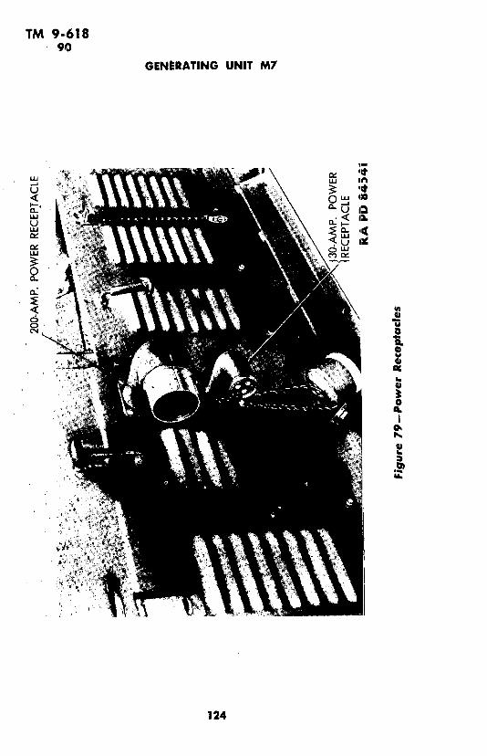
TM 9-61890
GENERATING UNIT M7
I.-,
LU An
<, o f":u a
~'Wo..% ~2
124
TM 9-61891
Section XVI
INSTRUMENT PANEL AND INSTRUMENTS
Paragoaph
Instrument panel ................................... 91Battery-charging ammeter . ........................... 92Oil pressure gage ................... ............ 93Temperature gage . ............................ 94Fuel gage (U. S. M. Co. units only) ..................... 95Tachometer . ....................................... 96Voltmeter ................................... .... 97Ammeter ........................................... 98Meter switch ....................................... 99Starter switch ..................................... 100Load switch .................................... ... 101Field rheostat ...................................... 102Ignition switch ...................................... 103125-volt light receptacle ....................... 104125-volt light switch .......................... :...... 105Lamp-dimming rheostat ................... ......... 1066-volt light receptacle .............. 1076-volt light switch .................. .·................ 086-volt extension cord receptacle ....................... 109Throttle control .................. ................. 110Choke control .......... : ......................... 111T-slot receptacle . ................... ............... 112Terminal block .................................... 113Fuse block ...................... ............. 114
91. INSTRUMENT PANEL (figs. 8 and 80).a. Construction. The instrument panel is of sheet-steel, aid is
located behind the rear left-hand door, above the alternator. It is heldin place by four U-type steel clips bolted to-brackets welded to hous-ing uprights.
b. Functioning. The instrument panel carries all the controls andgages necessary to the starting, stopping, and general operation andcontrol of the unit, with the exception of the fuel gage, which ismounted on the instrument panel only in the case of U.S.M. units(fig. 80). Other manufacturers make use of a mechanical gage set intothe fuel tank (fig. 39). For convenience, the fire extinguisher ismounted at the right of the panel (fig. 14). The wiring diagrams(figs. 83 and 83A) show how the instruments are connected to theelectrical circuit.
125

TM 9-61891
GENERATING UNIT M7
_3 _ ,_ 1
Figure 80-Instrument Panel U. S. M. Co.
RA PD 56996
Figure 81--nstrument Panel-Starter and Control Group126

TM 9-61891-93
INSTRUMENT PANEL AND INSTRUMENTS
a. Description. The battery-charging ammeter, in the upper left-hand corner of the instrument panel, indicates the charge and dischargecurrents of the 6-volt battery.
b. Removal.(1) REMOVE AMMETER. Remove nuts and star washdrs holding
bracket against the rear of the panel, and remove bracket clips. Takeoff stop nuts attaching leads, and remove leads. Remove ammeter.
c. Installation.(1) INSTALL AMMETER. Insert ammeter through the face of the
instrument panel, and attach bracket clips over studs with nuts andstar washers. Attach two wires marked '"CG" to right connection, andwire marked "B" to left connection, with elastic stop nuts.
93. OIL PRESSURE GAGE.a. Description. The oil pressure gage is at the extreme left on
the instrument panel, below the battery-charging ammeter. It is of theautomotive type, and indicates pounds pressure per square inch. Withthe engine running at 1,200 rpm, the gage should indicate 25-poundpressure, if the engine is fully warmed up.
b. Removal.(1) REMOVE LINE. Take nut from inverted flare tube fitting at
back of gage (fig. 84), and remove line.(2) REMOVE GAGE. Take nuts and star washers from bracket.
Remove bracket and gage.127

TM 9-61893-94
GENERATING UNIT M7
'l *7 =5lj 6 5l
22.
r-- ------ ---.--- ---. ------ -----------
8- c. A 73 C Tl A s < Fl FZ AtIF Al an CG 64 *1 4
RA PD 57003
Figure 83-Wiring Diagram--(Key on Figure 83A)
c. Installation.(1) ATTACH OIL LINE. Insert gage through face of instrument
panel. Connect oil line from base of oil filter to inverted flare tubefitting.
(2) INSTALL GAGE. Secure gage to panel with bracket attached tostuds by nuts and star washers.
94. TEMPERATURE GAGE.a. Description. The temperature gage is located in the lower
left-hand corner of the instrument panel. It indicates the temperatureof the water in the engine. This should be maintained at between 160degrees and 180 degrees F, while operating generating unit.
128

TM 9-61894
INSTRUMENT PANEL AND INSTRUMENTS
#xis Ces Ouz£
"
II,
SW O N TOAILER
.9 ..9 .9I"at--___ __J
29
125-VOLT AC CIRCUIT 6 VOLT BATT. CIRCUIT-LOAD RECEPTACLE 22- RECEPT. FOR BRAKES AND LIGHTS
2- LOAD SWITCH 23 - RECEPT. FOR EXTENSION CORD3- FUSE - 200 AMPS. 24- LIGHT4 - AMMETER 25 -LIGHT SWITCH- VOLTMETER 26- IGNITION SWITCH
6 - RHEOSTAT 27 - FUSE7 --LIGHTS 29- AMMETER8- SWITCH, 125-V. LIGHTS 30-STARTER SWITCH9-FUSES CG-CHARGING GENERATOR
10- RECEPTACLE.-EXTENSION CORD CR - CHARGING VOLTAGE11 -METER SWITCH REGULATOR12--TERMINAL BLOCK IC-IGNITION COIL13--CURRENT TRANSFORMERS D - DISTRIBUTOR14- RECEPTACLE, POWER TOOLS SM- STARTER MOTOR15-RHEOSTAT, LIGHT DIMMING
200-OHM, I TAPER, 1 AMP.16- LOAD RECEPTACLE, 30 AMPS.,
C80109SMALL WIRE COLOR CODE
LINE A-- RED EXCITER-Al BLACKLINE B--GREEN + .A2 WHITELINE C - BLUE 6 VOLTS YELLOW
Figure 83a-Wiring Diagram RA PD 57003A
b. Removal.(1) REMOVE LINE FROM ENGINE. Unscrew temperature indicator
bulb from engine head (fig. 85).(2) REMOVE GAGE AND LINE. Take off nuts and star washer hold-
ing bracket to panel, and remove gage.
e. Installation.
(1) ATTACH TEMPERATURE LINE. Insert gage in instrument panel,and install bulb at end of gage line in tapped hole in engine head.
129
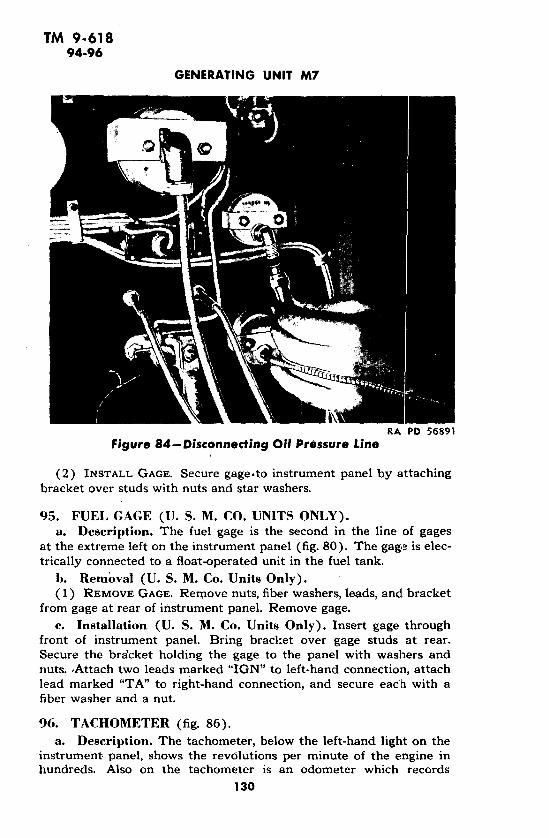
TM 9-61894-96
GENERATING UNIT M7
RA PD 56891Figure 84-Disconnecting Oil Pressure Line
(2) INSTALL GAGE. Secure gage.to instrument panel by attachingbracket over studs with nuts and star washers.
95. FUEL GAGE (U. S. M. CO. UNITS ONILY).a. Description. The fuel gage is the second in the line of gages
at the extreme left on the instrument panel (fig. 80). The gage is elec-trically connected to a float-operated unit in the fuel tank.
h. Removal (U. S. M. Co. Units Only).(1) REMOVE GAGE. Remove nuts, fiber washers, leads, and bracket
from gage at rear of instrument panel. Remove gage.c. Installation (U. S. M. Co. Units Only). Insert gage through
front of instrument panel. Bring bracket over gage studs at rear.Secure the bra'cket holding the gage to the panel with washers andnuts. ,Attach two leads marked "IGN" to left-hand connection, attachlead marked "TA" to right-hand connection, and secure each with afiber washer and a nut.
96. TACHOMETER (fig. 86).a. Description. The tachometer, below the left-hand light on the
instrument panel, shows the revolutions per minute of the engine inhundreds. Also on the tachometer is an odometer which records
130
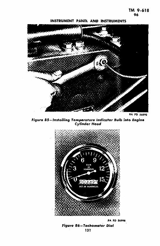
TM 9-61896
INSTRUMENT PANEL AND INSTRUMENTS
RA PD 56892
Figure 85-Installing Temperature Indicator Bulb into EngineCylinder Head
RA PD 56998
Figure 86-Tachometer Dial131

TM 9-61896-98
GENERATING UNIT M7
the total number of revolutions of the engine, also in hundreds ofrevolutions.
h. Removal.(1) REMOVE LINE. Disconnect line by removing swivel nut from
connector elbow.(2) REMOVE TACHOMETER. Take out bracket holding tachometer
to panel by removing elastic stop nuts. Remove tachometer.c. Installation.(1) ATTACH TACHOMETER TO PANEL. Insert tachometer in panel,
and secure by fastening bracket to tachometer and against panel withelastic stop nuts.
(2) ATTACH TACHOMETER LINE. Bring tachometer line to connec-tion elbow at bottom of tachometer, and secure with swivel nut.
97. VOLTMETER.a. Description. The voltmeter, just right of the tachometer on
the instrument panel, indicates the voltage of the exciter current andthe voltage of the current generated by the unit, which is normally125 volts. At this point on the dial is a red line. For procedure inobtaining these readings, see paragraph 8 c, and figures 11 and 12.
h. Removal.(1) REMOVE VOLTMETER FROM PANEL. Hold elastic stop nuts
on back of panel, and unscrew the four corner bolts on face of volt-meter. Removing these bolts will release two 4-wire straps.
(2) REMOVE LEADS. Take elastic stop nuts from the connectionson the back of the voltmeter. Remove leads and voltmeter.
c. Installation.(1) INSTALL VOLTMETER ON PANEL. Hold voltmeter on face of
instrument panel with mounting holes in meter over mounting holesin panel. Insert bolts through holes. On top bolts at rear of panel,place the wire clips that hold the two wires from the 125-volt lampsocket. On bottom bolts, place clips to engage the six wires that passunderneath the meter. Hold bolts and elastic stop nuts over the clipson the bolts.
(2) CONNECT LEADS. To the right-hand connection post, attachlead marked "11." To the left-hand post attach lead "9." Screw onelastic stop nuts.
98. AMMETER.a. Description. The ammeter is centrally located on the instru-
ment panel opposite the voltmeter. The ammeter ind:icates theamperage of the current delivered in the phases of the circuit. Seeparagraph 8 c, and figure 12.
h. Removal.(1) REMOVE AMMETER FROM PANEL. Hold elastic step nuts on
132
TM 9-61898-100
INSTRUMENT PANEL AND INSTRUMENTS
back of panel, and unscrew the four corner bolts on the face of theammeter. Removing these bolts will release a 3-wire strap held byeach of the bolts on the right-hand side of the meter.
(2) REMOVE LEADS. Take elastic stop nuts from the connectionson the back of the ammeter. Remove leads and ammeter.
c. Installation.(1) INSTALL AMMETER ON PANEL. Hold ammeter on face of panel
with mounting holes in meter over mounting holes in panel. Insertbolts through holes. On each right-hand bolt at rear of panel, place a3-wire clip to engage two wires marked "23" and one wire marked"24." Hold bolts, and screw elastic stop nuts on bolt ends.
(2) CONNECT LEADS. To the right-hand connection post, attachlead marked "3." To the left-hand post attach lead marked "1."
99. METER SWITCH.a. Description. The meter switch, centrally located on the instru-
ment panel, connects the voltmeter and ammeter simultaneously toeach phase of the circuit as the switch knob is turned to "A," "B," and"C" positions. With the knob turned to a fourth position, marked"EXC," the voltmeter shows the exciter voltage and the ammeter isdisconnected. See paragraph 8 c, and figures 11 and 12.
100. STARTER SWITCH (fig. 81).a. Description. The engine starter, or cranking switch, is mounted
on the left side of the instrument panel, directly below the throttleand choke knobs. It is of the conventional automotive type.
b. Removal.(1) REMOVE LEADS. Take off elastic stop nuts and washers from
connections on the back of the starter switch, and remove leads.(2) REMOVE SWITCH. Hold screws through face plate. Remove
nuts and lock washers at rear of board. Remove face plate from frontof panel and switch block from rear.
c. Installation.(1) MOUNT SWITCH. Place switch, with face plate removed, in
position at the rear of the instrument panel, the button projectingthrough and the mounting holes lined up with holes through the panel.Pass face plate over button and install switch by connecting face plateand switch through panel with screws, lock washers, and nuts. Holdscrews and attach nuts.
(2) CONNECT LEADS. To the right-hand connection on the starterswitch, attach lead marked "SM" and secure with elastic stop nut.To the left-hand connection, attach lead marked "B+." Secure withelastic stop nut.
133

TM 9-618101-103
GENERATING UNIT M7
101. LOAD SWITCH.a. Description. The load switch, which is the switch that con-
trols the delivery of current to the power receptacles and from themto the load, is a lever type. It is located on the right side of the instru-ment panel, below the unit name plate. When handle is in top position,the current is "ON." Bottom position is "OFF." Bolted to the back ofthe load switch is a panel holding the three 200-ampere fuses, three30-ampere fuses, and the two current transformers.
102. FIELD RHEOSTAT.a. Description. The field rheostat knob is located toward the bot-
tom of the instrument panel, just left of center. It controls the outputvoltage of the unit. To increase the voltage of the current delivered,the knob is turned counterclockwise. The minimum voltage position,which is also the starting and stopping position, is with the knobturned clockwise as far as possible.
h. Removal.
(1) REMOVE LEADS. Disconnect leads from binding posts. at rearof rheostat by removing nuts and lock washers.
(2) REMOVE KNOB. Take out vertical screw holding rheostit knobto shaft, and remove knob.
(3) REMOVE RHEOSTAT. Take out two screws on the face of theinstrument panel holding rheostat to panel.
e. Installation.
(1) ATTACH RHEOSTAT. Attach rheostat to instrument panel withscrews through panel into rheostat tapped holes.
(2) INSTALL KNOB. Slip knob over rheostat shaft, and secure toshaft with vertical screw.
(3) ATTACH LEADS. Attach lead marked "A-i" to the left-handbinding post of the rheostat, and secure with nut and lock washer.Attach lead marked "F" to center post of rheostat, and install a wirejumper from center post to right-hand post. Secure with nuts andlock washers.
103. IGNITION SWITCH (fig. 81).
a. Description. The toggle-type, single-pole, single-throw ignitionswitch is at the upper left in the control group on the left side of theinstrument panel. This switch controls the starting and ignition sys-tem (section XIV).
b. Removal.(1) REMOVE LEADS. Take out screws holding down, leads at the
back of the switch, and remove leads.(2) REMOVE SWITCH. Remove ring nut from switch on front of
instrument panel. Remove nut from switch on rear of panel. Removeswitch.
134

TM 9-618103-105
INSTRUMENT PANEL AND INSTRUMENTS
c. Installation.(1) INSTALL SWITCH. Set switch in position on rear of panel with
neck projecting through hole. Screw on ring nut so it is just flush withedge of neck. In back of the panel, screw nut tightly against panel.
(2) CONNECT LEADS. Remove screw connectors from switch. Toone pole of switch, connect lead marked "IGN." To the other pole,connect lead "CG." Replace the screws.
104. 125-VOLT LIGHT RECEPTACLE.a. Description. At the top of the instrument panel are two 125-
volt rubber-mounted light receptacles. They are controlled by the125-volt light switch in the center of the panel, and the amount of theillumination given is regulated by the lamp-dimming rheostat setbetween them.
b. Removal.(1) REMOVE LEADS. Trace lead "16" to lamp-dimming rheostat;
remove nut and lock washer, and remove lead. Trace lead "23" to125-volt light switch; remove screw and lead.
(2) REMOVE RECEPTACLE. Hold screws, remove nuts and lockwashers at back of instrument panel, and remove receptacle.
c. - Installation.(1) INSTALL RECEPTACLE. Bring receptacle to mounting holes in
the front of the panel. Install with bolts through receptacle and panel,lock'washers, and nuts at rear.
(2) INSTALL LEADS. Connect receptacle lead "16" to the left con-nection of the lamp-dimming rheostat. Secure with lock washer andnut. Connect receptacle lead "23" to the top left connection of the125-volt light switch. Secure leads with screws.
105. 125-VOLT LIGHT SWITCH.a. Description. The toggle-type, double-pole, single-throw, 125-
volt light switch is centrally located on the instrument panel belowthe ammeter. This switch turns on the 125-volt lamps at the top ofthe panel.
b. Removal (par. 103 b).
c. ' Installation.(1) INSTALL SWITCH. Remove ring nut from switch. Set switch
in position on panel with neck projecting through hole. Screw on ringnut so that it is just flush with edge of neck. In back of the panel,screw nut tightly against panel. Secure ring nut against front of panel.
(2) CONNECT LEADS. Remove screw connectors. To the top leftconnection, bring two leads marked "23." To the top right connec-tion, bring lead marked "24." The lower left connection takes twoleads marked "14." The lower right connection takes two leadsmarked "12." Secure leads with screws.
135

TM 9-618106-108
GENERATING UNIT M7
106. LAMP-DIMMING RHEOSTAT.a. General. Centrally located at the top of the instrument panel
is the lamp-dimming rheostat, used to dim the 125-volt lamps,b. Removal.(1) REMOVE LEADS. Take off nuts and lock washers from con-
nections on rear of rheostat. Remove leads.(2) REMOVE KNOB. Take out screw through rheostat knob, and
slide knob off.(3) REMOVE RHEOSTAT. Unscrew nut holding rheostat shaft
sleeve against the face of the panel, and slide rheostat out at the backof the panel.
c. Installation.(1) SECURE IN PLACE. Install rheostat at back of panel with shaft
projecting through panel. Secure in place with nut on shaft sleeveset tight against face of panel.
(2) INSTALL KNOB. Twist knob on shaft, and secure by tighteningscrew through knob against flattened part of shaft.
(3) CONNECT LEADS. Install two leads marked "16" to 1he leftconnection on the rheostat. Install lead marked "24" on the centerpost. Secure with lock washers and nuts.
107. 6-VOLT LIGHT RECEPTACLE.a. Description. A 6-volt light receptacle is located at the top of
the instrument for use in illuminating the panel at times when theunit is not running and the 125-volt circuit cannot be used. This lightis controlled by the toggle switch at the upper right in the controlgroup above the starter button.
b. Removal.(1) REMOVE LEAD. Loosen horizontal screw through the body of
the receptacle, and remove lead from center of back.(2) REMOVE RECEPTACLE. Unscrew nut from the tapped recep-
tacle ring; remove lock washer and receptacle.c. Installation.(1) SECURE RECEPTACLE IN PLACE. Insert receptacle through
panel until rim holds it in place. Install lock washer and nut cn backof receptacle.
(2) INSTALL LEAD. Insert lead wire "62" into connection hole atback of receptacle. Secure wire in place by tightening horizontalscrew through body of receptacle.
108. 6-VOLT LIGHT SWITCH.a. Description. The toggle-type, single-pole, single-throw, 6-volt
light switch is at the upper right in the control group on the left sideof the instrument panel. This switch controls the 6-volt light: whichfurnishes illumination when the unit is not running.
136

TM 9-618108-110
INSTRUMENT PANEL AND INSTRUMENTS
h. Removal. Follow procedure outlined in paragraph 103 lo.
c. Installation.(1) INSTALL SWITCH. Remove ring nut from switch. Set switch
in position on panel with neck projecting through hole. Screw on ringnut so that it is just flush with edge of neck. In back of the panel,screw nut tightly against panel. Secure ring nut against front of panel.
(2) CONNECT LEADS. Remove the screw connectors from theswitch. To one pole connect lead marked "62." To the other pole con-nect two leads marked "61." Replace the screws.
109. 6-VOLT EXTENSION CORD RECEPTACLE.a. Description. A receptacle to take the 6-volt trouble light,
which is carried in the tool box, is provided at top center in the controlgroup above the starter button (fig. 81).
b. Removal. Follow procedure outlined in paragraph 107.
c. Installation.(1) SECURE RECEPTACLE IN PLACE. Insert receptacle through
panel until rim holds it in place. Install lock washer and nut on backof receptacle.
(2) INSTALL LEAD. Insert lead wire "61" into connection hole atback of receptacle. Secure wire in place by tightening horizontalscrew through body of receptacle.
110. THROTTLE CONTROL.a. Description. The throttle knob is at the lower left in the con-
trol group on the left side of the instrument panel (fig. 81). This knobhas a wire connection with a valve in the throttle box below thecarburetor. Pulling out the knob reduces the amount of fuel mixturesupplied the engine, and reduces engine speed.
b. Removal.(1) REMOVE THROTTLE CONTROL WIRE. Loosen clamping screws
holding throttle wire and casing to carburetor throttle lever arm (fig.87), and remove wire. Loosen bolt through support bracket on top ofengine, and remove wire from bracket.
(2) REMOVE CONTROL. Unscrew nut from throttle knob casingon back of instrument panel, and remove nut and lock washer. Re-move knob, casing, and wire from the front of the instrument panel.
c. Installation.(1) INSTALL CONTROL. Insert throttle wire and casing through in-
strument panel hole until rim of knob casing holds against front ofpanel. Carry lock washer and nut over wire, and tighten nut onthreaded section of knob casing until the assembly is held securely inplace.
(2) CONNECT TO CARBURETOR. Carry wire casing to clamp on topof engine, loosen clamp screw, secure wire, and tighten screw of engine
137

TM 9-618110-112
GENERATING UNIT M7
with wire in place. Bring wire to throttle lever arm on carburetor,hold lever arm forward, and connect wire to binding post on arm.
111. CHOKE CONTROL.a. Description. The choke knob is at the lower right in the con-
trol group on the left side of the instrument panel (fig. 81).- This knobhas a wire connection to a valve in the carburetor that regulates thecarburetor air supply. Pulling out the knob cuts down on the amountof air to the carburetor.
b. Removal.(1) REMOVE CHOKE CONTROL WIRE. Loosen clamping screws
holding choke wire and casing to carburetor valve arm, and removewire. Loosen bolt through support bracket on top of engine, andremove wire from bracket.
(2) REMOVE CONTROL. Unscrew nut from choke knob casing onback of instrument panel, and remove nut and lock washer. Removeknob, casing, and wire from the front of the instrument panel.
c. Installation.(1) INSTALL CONTROL. Insert choke wire and casing through in-
strument panel hole until rim of knob casing holds against front ofpanel. Carry lock washer and nut over wire at back of instrumentpanel, and tighten nut on threaded section of knob casing in frontof panel until the assembly is held securely in place.
(2) CONNECT TO CARBURETOR. Carry wire casing to clamp on topof engine, loosen clamp screw, secure wire, and tighten screw withwire in place. Bring wire to carburetor, hold lever arm forward, andconnect wire to binding post on choke lever arm.
112. T-SLOT RECEPTACLE.a. Description. One T-slot receptacle, of the regular ba:se recep-
tacle type, is provided on the instrument panel, and four on the apronbelow. The one on the panel is intended for use with 125-volt troublelight carried in the tool box. The receptacles on the apron are forelectric tools.
b. Removal.(1) REMOVE LEADS. Unscrew connector screws at back Df recep-
tacle, and take off leads.(2) REMOVE RECEPTACLE. Take out the two screws holding the
receptacle to the panel, and remove receptacle.
c. Installation.(1) PANEL RECEPTACLE.(a) Install Receptacle. Insert receptacle through hole from rear of
instrument panel, alining tapped mounting holes in receptacle's earswith mounting holes in panel. Secure receptacle to panel with screwsthrough panel and receptacle.
138

TM 9-618112
INSTRUMENT' PANEL AND INSTRUMENTS
! a. RA PD 56897
Figure 87-Throttle Wire Installation
Figure 88--Terminal Block139

TM 9-618112-114
GENERATING UNIT M7
RA PD 57000Figure 89-30-Ampere Fuses and T-Slot Receptacles
(b) Install Leads. Attach lead marked "14" to one receptacle con-nection, lead marked "12" to the other. Secure with screws.
(2) APRON RECEPTACLES.(a) Insert receptacle through hole from rear of instrument panel,
alining tapped mounting hole in receptacle with mounting-holes inpanel. Secure receptacle to panel with screws through panel andreceptacle.
(b) Install Leads. Attach two leads marked "1A" to one connec-tion, one lead marked "9" to the other connection. Secure with screws.The end receptacle of the series will take only one "14" lead.
113. TERMINAL BLOCK (fig. 88).a. Description. An 8-position terminal block in back of the in-
strument panel handles connections for both 6-volt and 125-volt cir-cuits. A center label strip identifies the connections. The third and theeighth positions are unused. The block is mounted on arms weldedto the load switch bracket.
lb. Maintenance. Periodically, make a check on the cable con-nections at the terminal block. Check for clean and tight connections.Connections showing signs of corrosion must be removed arnd thor-oughly scraped clean.
114. FUSE BLOCK (fig. 89).a. Description. Two double-fuse blocks are located on the under
side of the instrument panel bottom ledge. These fuse blocks holdfour 30-ampere fuses connected with the four T-slot receptacles on theinstrument panel apron,
140

TM 9-618114-116
PAINTING
b. Maintenance. Periodically, tighten all cable connections onfuse clips. Remove and clean all corroded cable connections.
Section XVII
PAINTINGParagraph
General .......................................... 115
Preparing for painting ................................ 116
Painting metal surfaces ............................... 117
Paint as a camouflage ................................ 118
Removing paint ..................................... 119
Painting lubricating devices .......................... 120
115. GENERAL.a. Ordnance materiel is painted before it is issued to the using
arms, and one maintenance coat per year will ordinarily be amplefor protection. With but few exceptions, this materiel will be paintedwith ENAMEL, synthetic, olive-drab, lusterless. The enamel may beapplied over old coats of long oil enamel and oil paint previouslyissued by the Ordnance Department, if the old coat is in satisfactorycondition for repainting.
b. Paints and enamels are usually issued ready for use, and areapplied by brush or spray. They may be brushed on satisfactorilywhen used unthinned in the original package consistency, or whenthinned no more than 5 percent by volume with THINNER, forsynthetic enamels. The enamel will spray satisfactorily when thinnedwith 15 percent by volume of THINNER, for synthetic enamels.(Linseed oil must not be used as a thinner, since it will impart a lusternot desired in this enamel.) If sprayed, it dries hard enough for re-painting within 1/2 hour, and dries hard in 16 hours.
c. Complete information on painting is contained in TM 9-850.
116. PREPARING FOR PAINTING.a. If the base coat on the materiel is in poor condition, it is more
desirable to strip the old paint from the surface with REMOVER,paint and varnish, than to use sanding and touch-up methods. Afterstripping, it will then be necessary to apply a primer coat.
b. PRIMER, synthetic, refinishing, should be used on wood as abase coat for synthetic enamel. It may be applied either by brushingor spraying. It will brush satisfactorily as received, or after the addi-tion of not more than 5 percent by volume of THINNER paint,
141
TM 9-618116-118
GENERATING UNIT M7
volatile mineral spirits. It will be dry enough to touch in 30 r.inutes,and hard in 5 to 7 hours. For spraying, it may be thinned with notmore than 15 percent by volume of THINNER paint, volatile mineralspirits. Lacquers must not be applied to the PRIMER, synthetic, re-finishing, within less than 48 hours.
c. PRIMER, synthetic, rust-inhibiting, for bare metal, should beused on metal as a base coat. Its use and application are similar tothat outlined in subparagraph h, above.
d. The success of a job of painting depends partly on the selectionof a suitable paint, but also largely upon the care used in preparingthe surface prior to painting. All parts to be painted should be freefrom rust, dirt, grease, kerosene, oil, and alkali, and must be dry.
117. PAINTING METAL SURFACES.a. If metal parts are in need of cleaning, they should be washed in
a liquid solution consisting of 1/2 pound of SODA. ASH in 8 quarts ofwarm water, then rinsed in clear water and wiped thoroughly dry.Wood parts in need of cleaning should be treated in the same manner,but the alkaline solution must not be left on for more than a fewminutes, and the surfaces should be wiped dry as soon as they arewashed clean. When equipment is in fair condition, and marred onlyin spots, the bad places should be touched up with ENAMEL, syn-thetic, olive-drab, lusterless, and permitted to dry. The whole surfacewill then be sandpapered with PAPER, flint, Class B, No. 1, and afinish coat of ENAMEL, synthetic, olive-drab, lusterless, applied, andallowed to dry thoroughly before the materiel is used. If the! equip-ment is in bad condition, all parts should be thoroughly sanded withPAPER, flint, Class B, No. 2, or equivalent, given a coat of PRIMER,synthetic, refinishing, and permitted to dry for at least 16 hours.Then sandpaper with PAPER, flint, Class B, No. 2/0, wipe free fromdust and dirt, and apply a final coat of ENAMEL, synthetic, olive-drab, lusterless. Allow to dry thoroughly before the materiel is used.
118. PAINT AS A CAMOUFLAGE.a. Camouflage is now a major consideration in painting ordnance
equipment, with rust prevention secondary. The camouflage plan atpresent employed utilizes three. factors: color, gloss, and stenciling.
(1) COLOR. The equipment is painted with ENAMEL, synthetic,olive-drab, lusterless, which was chosen to blend in reasonably wellwith the average landscape.
(2) GLOSS. The new lusterless enamel makes equipment difficultto see from the air or from relatively great distances over land. Aunit painted with ordinary glossy paint can be detected more easilyand at greater distances.
142

TM 9-618118-120
PAINTING
(3) STENCILING. White stencil numbers have been eliminated be-cause they can be photographed fr)m the air. ENAMEL, synthetic,stenciling, lusterless, blue-drab, is now used, which cannot be so photo-graphed. It is illegible to the eye al: distances exceeding 75 feet.
h. Preserving Camouflage.(1) Continued friction or rubbing must be avoided, as it will
smooth the surface and produce a gloss. The unit should not bewashed more than once a week. Care should be taken to see that thewashing is done entirely with a sponge or a soft rag. The surfaceshould never be rubbed or wiped, except while wet, or a gloss willdevelop.
(2) It is not desirable that equipment, painted with lusterlessenamel, be kept as clean as equipment was kept when glossy paintwas used. A small amount of dus: increases the camouflage value.Grease spots should be removed withl SOLVENT, dry-cleaning. What-ever portion of the spot cannot be so removed should be allowed toremain.
(3) Continued friction of wax-treated tarpaulins on the sides of avehicle will also produce a gloss which should be removed with SOL-VENT, dry-cleaning.
(4) Tests indicate that repainting with olive-drab enamel will benecessary once yearly, with blue-drab stenciling enamel twice yearly.
119. REMOVING PAINT.a. After repeated paintings, the paint may become so thick as to
crack and scale off in places, presenting an unsightly appearance. Ifsuch is the case, remove the old paint by use of a lime-and-lye solu-tion (see TM 9-850 for details) or REMOVER, paint and varnish.It is important that every trace of lye or other paint remover be com-pletely rinsed off, and that the equipment be perfectly dry beforerepainting is attempted. It is preferable that the use of lye solutionsbe limited to iron or steel parts. If used on wood, the lye solutionmust not be allowed to remain on the surface for more than a minutebefore being thoroughly rinsed off, and the surface wiped dry withrags. Crevices or cracks in wood should be filled with putty, and thewood sandpapered before refinishing.
120. PAINTING LUBRICATING DEVICES.a. A circle about 3/4 inch in diameter will be painted with
ENAMEL, red, water-resisting, around each joint of lubrication, suchas oil cups, grease fittings, oil holes, and similar lubricating devices, inorder that they may be readily lomated. Do not paint openings infittings through which lubricant pasres.
14:1

TM 9-618121
GENERATING UNIT M7
Section XVIII
STORAGE AND SHIPMENT
Paragraph
Domestic shipment .... ........................... 121Rail shipment ...................................... 122Limited storage ..................................... 123
121. DOMESTIC SHIPMENT.a. General. The Generating Unit M7, when mounted on trailer
chassis, will be shipped uncrated for domestic shipment by rail (par.122).
h. Preparation.(1) LUBRICATION. Lubricate unit in accordance with lubricating
instructions, section IV.(2) FUEL. Drain fuel-from fuel tank.(3) BATTERY.(a) Disconnect battery lead terminals. Clean and tape the term-
inals, and secure away from the battery posts.(b) Apply coating of COMPOUND, rust-preventive, light, to bat-
tery posts.(c) Batteries shall be recharged before shipment if hydrometer
readings fall below 1.275.(4) PAINTING.(a) All painted surfaces that have become checked, pitted, or
rusted shall be thoroughly cleaned and rust spots removed.(b) Apply coating of PRIMER, synthetic, rust-inhibiting to bare
metal as a base for surfaces to be repainted.(c) Apply coating of ENAMEL, synthetic, olive-drab, lusterless,
and allow to dry thoroughly.(5) APPLICATION OF PRESERVATIVE. Application of preservative
should be accomplished immediately after cleaning.(a) Unpainted metal surfaces should be treated with COM-
POUND, rust-preventive, thin film, by spraying or brushing. Thispreservative does not require heating nor further solvent dilution be-fore application.
(6) INSPECTION. Make a systematic inspection just before ship-ment or storage, and list all missing or broken items that are not re-placed or repaired, and attach list to unit.
(7) ENGINE PREPARATION. Instructions for preparation of enginesfor shipment will be found in IOSSC-(j), Introduction to OrdnanceStorage and Shipment Chart, section (j), "Preparation of UnboxedOrdnance Materiel for Shipment."
144

TM 9-618122
STORAGE AND SHIPMENT
122. RAIL SHIPMENT.a. Inspection of Railroad Cars. Inspect floors of all railroad
cars to be sure they are sound, and that all nails and other projectionshave been removed.
h. Brake Wheel Clearance. Each railroad car must be loadedwith a resulting brake wheel clearance of at least 6 inches in front, ontop, and at each side of the brake wheel.
c. Clearance Limits. The height and width of load must bewithin the clearance limits of the railroads over which it is to bemoved. Army and railroad officials must check all clearances prior toeach move.
d. Placarding. Each railroad car must be placarded "DO NOTHUMP."
e. Brake. Apply hand brake.f. Blocking Trailer and Unit on Railroad Car (fig. 90).(1) TRAILER WHEELS.(a) Blocks C. Place one block C across the front of the trailer tires,
and one at the rear tires (2 blocks C required). These blocks will beat least 8 inches longer than the over-all width of the tires.
(b) Cleats B. Place two cleats B to the front of block C at eachwheel (8 cleats B-required). Nail the lower cleat to the car floor withthree 40-penny nails, and nail the top cleat to the cleat below withthree 40-penny nails.
(c) Cleats E. Place one cleat E against the outside face of eachwheel on the top of block C (2 cleats E required). Nail cleats E toeach block C with four 40-penny nails.
(d) Strapping Trailer Wheels D. Secure unit at each wheel bystrapping, consisting of four strands, two wrappings of No. 8 gage,black annealed wire. Pass wire through opposite openings in wheels,and attach at the nearest stake pockets of the car. Tighten wire suffi-ciently to remove slack.
NOTE: When box cars are used, strapping should be applied insimilar fashion, and attached to car floor by use of blocking or anchorplates.
(e) Position trailer chassis support legs at the four corners of theunit.
(2) DRAWBAR.
(a) Block F. Place one block F under tongue of unit in center, andtoenail to car floor, using four 40-penny nails (one block F required).
(b) Cleats G. Locate on floor against four sides of block F. Nail tofloor, using four 20-penny nails in each cleat (four cleats G required).
(c) Braces H. Cut braces long enough to extend from floor to topof block F. Nail to block F, cleats G, and the car floor with three 20-penny nails in each end (four braces H required).
145
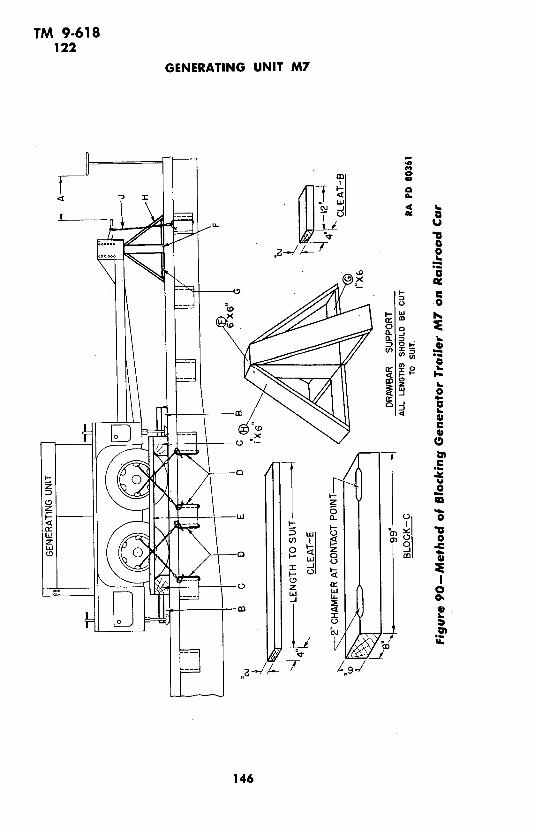
TM 9-618122
GENERATING UNIT M7
-, I .
f, UUa .
'_
e~
o
o
a: a<m~m
oe
123~~~~~~~~~~~46
@3
z~~~~~~~~~~~~~~~~
@3
<I- Cz 0
n I I- -I
z a, *6
w~~~~ o
zD z 30 0 ~~-- 0M 4
0
r-I Li
~I'u-~~
iili9-/
146

TM 9-618122-123
STORAGE AND SHIPMENT
(d) Strapping Drawbar J. Secure drawbar at stake pocket on eachside of car by looping wire, 6 strands, 2 wrappings, No. 8 gage, blackannealed around lunette. Twist each wire taut with rod or bolt.
123. LIMITED STORAGE.a. Trailer and unit will be prepared for limited storage as de-
scribed in paragraph 121.
b. Periodical inspections shall be made while the materiel is stored,to note among other things, general condition, missing parts, and theneed for repairs. If found to be corroding at any part, the entire pro-cedure for preparation for storage herein listed shall be repeated.
147

TM 9-618124-125
GENERATING UNIT M7
Section XIX
REFERENCES
Paragraph
Standard nomenclature lists ........................... 124
Explanatory publications ............................. 125
124. STANDARD NOMENCLATURE LISTS.
a. Trailer, generator, M7 ................... SNL F-226
b. Unit, generating, M7 ..................... SNL F-283
Current Standard Nomenclature lists are as tabu-lated here. An up-to-date list of SNL's is main-tained as the "Ordnance Publications for Sup-ply Index" now published in ............... OFSB 1-1
125. EXPLANATORY PUBLICATIONS.
a. Automotive electricity ................... TM 10-580
b. Automotive lubrication .................. TM 10-540
c. Camouflage .................... ......... FM 5-20
d. Chassis, body and trailer units ............. TM 10-560
e. Chemical decontamination materials and equip-ment ................................ TM 3-.220
f. Cleaning, preserving, lubricating, and weldingmaterials and similar items issued by theOrdnance Department ................ TM 9-850
g. Cold weather lubrication and service of artil-lery equipment ....................... OFSB 6-5
h. Cold weather lubrication and service of combatand automotive equipment .............. OFSB 6-11
i. Defense against chemical attack ........... FM 2 1-40
j. Detailed lubrication instructions, ordnance ma-teriel ............................... OFSB 6-series
k. Fuels and carburetion .................... TM 10-550
1. Hand, measuring, and power tools .......... TM 113-590148
TM 9-618125
REFERENCES
m. List of publications for training ........... FM 21-6
n. Maintenance and care of pneumatic tires andrubber treads ......................... TM 31-200
o. Motor transport ........................ FM 25-10
p. Motor transport inspections ............... TM 10-545
q. Motor vehicles ......................... AR 850-15
r. Ordnance storage and shipment chart--Group F ............................ OSSC F
s. Storage of motor vehicle equipment ...... :.. AR 850-18
t. The internal combustion engine ............ TM 10-570
u. Trailer, generator, M7 .................... TM 9-881
149
TM 9-618
GENERATING UNIT M7
INDEX
A Page No. Page No.
Adjustment of governor ....... 83-85 description . ........... 81
Air cleaner maintenance . .82
construction .............. 82-83 maintenance allocation ....... 43
lubrication ... ............... 25 removal and installation ....... 82
maintenance ................ 83 trouble shooting ........... 81-82
trouble shooting ............. 83 Characteristics of generating unit
Air filter, cleaning ... .......... 52 M 7 ...................... ... 2-3
Allocation of maintenance ..... 41-43 Choke, description and functioning 13
Alternator (See under Generating Choke control
system) maintenance allocation ....... 43
Ammeter removal' and installation ....... 138
description . ................ 132 Cleaning the cooling system .... 54-57
installation ................ 133 Cold weather accessories . ....... 37
maintenance allocation .. .... 43 Collector ring, inspection .... 119-120
location and functioning ..... 14Commutator, inspection ........ 123
removal . . ..... 132-133
Antifreeze solutions ............ 34 Condenstallation .erinstallation ................. 109
s maintenance allocation ....... 43
Battery removal .................... 107
care in extreme heat .......... 38 Coolant service .............. 56-57
description ................. 95 Cooling system
installation ........ 98-99 adjustment ............... 52
maintenance ........ 97 cleaning .................. 54-57
protection under unusual con- description .53
ditions ....... 34-35 fan ..... 58-59
removal ....... 97-98 fan belt ..... 59-60
trouble shooting .... ......... 95 monthly inspection .......... 23
Battery cables, maintenance allo- protection under unusual condi-
cation ...................... 43 tions ............ 34
Battery-charging ammeter radiator ... 57-58
location and functioning ....... 15 thermostat ................ 63-65
maintenance allocation ....... 43 trouble shooting ........... 53-54
removal and installation ....... 126 water pump ............ 60-63
Battery-charging generator Crankcase, lubrication . ......... 25
functioning ................. 99
maintenance ............. 100-102 Dmaintenance allocation ....... 43
removal and installation ....... 102 Deep water fording......... 39-40
trouble shooting ............. 100 Description
Battery-charging voltage regulator cooling system
generator, maintenance allocation 43 fan .................... 58
Bendix spring (See under Starting radiator ................ 57
motor) engineaccessories ............. 45-48
C construction ............ 44-45
Carburetor functioning ......... 48
adjustment .. ............... 52 specifications ......... 49
150

TM 9-618
INDEX
D--Cont'd Page No. Page No.Description-Cont'd Distributor points, maintenance
engine electrical system allocation ................... 43battery .................. 95 Domestic shipment ............ 144spark plugs ............... 109
engine lubrication system
oil pump ............... 91-92Eoil strainer ............... 91 Echelon duties .............. 41-42
exhaust system Engineexhaust pipe ............ 70-71 description ............... 44-49manifold ................. 67 lubrication ................ 32-33
frame .................... 44 maintenance ............. 50fuel system monthly inspection ...... 23
carburetor ................ 81 trouble shooting ........... 49-50fuel pump ............... 77 tune-up ............. ..... 50-52
generating systemalternator . . 117 Engine and generator controls.. 13-16alternator ................ 117
exciter ............... 120 Engine electrical systeminstrument panel and instruments battery .... .... .. 95-99
ammeter ............ 132 battery-charging generator.. 99-102battery-charging ammeter ... 127 description .......... ....... 94choke control .............. 138 distributor .............. 105-109field rheostat .............. 134 ignition coil ............ 103-105fuel gage ................. 130 monthly inspection ......... 23-24fuse block .......... ...... 140 protection under unusual condi-ignition switch ............ 134 tions ................. 34-35load switch ............... 134 spark plugs ............ 109-110meter switch .............. 133 starting motor ........... 110-114oil pressure gage .......... 127 trouble shooting ............ 95125-volt light receptacle..... 135 Engine lubrication system125-volt light switch........ 135 description .896-volt extension cord recepta- filter ........ ..... 90-91
cle .................. 137 oil pump ............... 91-926-volt light receptacle ...... 136 strainer ...... ...... 916-volt light switch ........ 136 trouble shooting .......... 89-90starter switch ..... 133T-slot receptacle ......... 138 Exciter (See under Generating sys-tachometer ........... 130-132 tem)temperature gage ........ 128 Exhaust pipeterminal block ............ 140 description ............... 70-71throttle control ........... 137 maintenance ................ 71voltmeter ................ 132 maintenance allocation ........ 43
Differences among models of gen- removal and installation....... 71erating units ................. 3 Exhaust system
Distributor description ................ 65-67lubrication ................. 28 exhaust pipe .............. 70-71maintenance ................ 51 flexible tube ................ 72maintenance allocation ....... 43 manifold ............... 67-70protection under unusual condi- monthly inspection .......... 23
tions ................... 34 muffler .... ...... 71-72trouble shooting ............. 105 trouble shooting ............. 67
151
TM 9-618
GENERATING UNIT M7
F Page No. G Page No.Fan Generator and exciter, care in
description ................. 58 flooded areas ............... 38-39installation ................. 59mainstallation ........... ...... 59 .Generator and exciter shaft bea::-maintenance ............. 58maintenance allocation ings,lubrication .......... 28removal .................. 58-59 Generator and starter, protectiontrouble shooting ............. 58 under unusual conditions ...... 34
Field rheostat Generating systemdescription ................. 134 alternatorfunctioning ................. 13 description ............... 117maintenance allocation ....... 43 maintenance .......... 119-120
Fire extinguisher, operation and trouble shooting ........ 117-119maintenance .............. 31 description ........... 114-115
Flexible tube, description ....... 72 exciterdescription ............... 120
Flood conditions ............ 38-39 maintenance ......... 120-123
Frame, description, trouble shoot- trouble shooting .......... 120ing, and maintenance ......... 44 monthly inspection .......... 24
Frame and canopy, monthly inspec- 30-ampere power receptacle ... 123tion ........................ 23 trouble shooting ......... 115-117
Frequency meter, location and 200-ampere power receptacle... 123
functioning . ............ 16 Generating unit M7
Fuel gage characteristics ......... 2-3maintenance allocation ... data................. ... 3removal and installation ....... 130 differences among models ..... 3
Fuel pump Governorcleaning . ............ 51 adjustment .............. 83-85description ................. 77 trouble shooting .......... 83maintenance ................ 79maintenance allocation ....... 43removal and installation ...... 79trouble shooting ......... 77-79 Ignition coil
Fuel system installation ............. 103-105air cleaner ................ 82-83 maintenance . ............. 103carburetor .. 81-82 removal........ ....... 103care in desert conditions ....... 38 Ignition switchdescription .............. 73 description ..... ........ 134fuel pump ............ 77-79 installation ............. 135fuel tank ........... 76 operation and controls ........ 13governor .......... 83-85 removal . ............. 134monthly inspection .. 23 Ignition systemthrottle box ................. 85 care in flooded areas ......... 39trouble shooting ........... 73-76 care in humid atmospheres .... 38
Fuel tank Inspectioncare in extreme heat .......... 38 after long operation .......... 22maintenance ...... . . .. ............ 76 after short operation .......... 22
Functioning of generating sys- during operation ............ 21temrn .................... 114-115 prestarting ................. 21
Fuse block, description .......... 140 weekly and monthly ........ 22-24
152

TM 9-618
INDEX
I-Cont'd Page No. Page No.Instrument panel and instruments Lubrication system
ammeter ............... 132-133 care in desert conditions ...... 38battery-charging ammeter .... 127 monthly inspection .......... 23choke control ............... 138field rheostat ..... .......... 134fuel gage .......... ......... 130 Mfuse block .............. 140-141 Maintenanceignition switch .......... 134-135 cold weather ........... 32instrument panel ............ 125 cooling systemlamp-dimming rheostat ....... 136 fan ...................... 58load switch ................. 134 radiator .................. 58meter switch . .............. 133 thermostat ......... 65monthly inspection .......... 24 water pump ........ 61oil pressure gage ........ 127-128 engine electrical system125-volt light receptacle ....... 135 battery .................. 97125-volt light switch .......... 135 battery-charging genera-6-volt extension cord receptacle. 137 tor ............ . 100-1026-volt light receptacle ......... 136 distributor ............ 106-1076-volt light switch ........ 136-137 ignition coil ......... 103starter switch ............... 133 spark plugs ......... 109-110tachometer ............. 130-132 starting motor ......... 113temperature gage ........ 128-130 engine lubrication systemterminal block ............ 140 oil filter .................. 90throttle control .......... 137-138 oil pump ................ 92T-slot receptacle ......... 138-140 oil strainer .............. >. 91voltmeter ...... ............. 132 exciter ................. 120-123
Intake and exhaust manifolds, fire extinguisher .... .... 31maintenance allocation ....... 42 frame ...... 44
fuel systemIntervals of lubrication ......... 25 al eair cleaner . ............ 83
carburetor ........... ..... 82L fuel pump ............ 79
Lamp-dimming rheostat fuel tank ............. 67location and functioning ...... 16 muffler .. 71removal and installation ....... 136 ..................... 140
terminal block .............. 140Light receptacles, maintenance Manifoldallocation ...... ............. 43 M i odescription ............... 67
Lighting switch, maintenance allo- installation ........... 69-70cation .......... . . 43 maintenance ............. .. 4367
Limited storage ............... 147 removal ................ 67-69Load switch Metal surfaces, painting ......... 142
description ................ 134 Meter switchlocation and functioning ..... 14-15 description ................. 133
Lubricating devices, painting ..... 143 functioning ................. 1'3Lubrication Muffler
lubrication guide .......... 25-28 construction ................ 71points serviced by ordnance per- installation ................. 72
sonnel ................ 28 maintenance ................ 71reports and records ......... 28-29 maintenance allocation ....... 43
153

TM 9-618
GENERATING UNIT M7
0 Page No. p Page No.Oil filter Paint(-ing)
installation ................. 91 as camouflage ......... 142-143lubrication ................. 25 lubricating devices ........... 143maintenance ................ 90 metal surfaces .............. 142removal ... ................ 90 preparation for .......... 141-142
Oil gage, maintenance allocation.. 43 removal .................... 143
Oil lines and fittings, maintenance Prestarting inspection .......... 21allocation ................... 43
Oil pressure gage Rdescription ................. 127 Radiatorinstallation ................. 128 description ................. 57location and functioning ...... 15 maintenance ................ 58removal ................... 127 trouble shooting ............. 57
Oil pump Rail shipment ........... 145-147description ............... 91-92 Reports and records of lubrica-maintenance ................. 92 tion ..................... 28-29
Oil strainermaintenance allocation ....... 43 Sremoval and installation ...... 91
Oilcan points .. - -28 6-volt extension cord receptacle,Oilcan points .................. 28removal and installation .... ... 137
125-volt light receptacle, descrip-tion . ................ 15..... .1 6-volt light receptacle, removal and
installation .............. ... 136125-volt light switch, removal and installation 136installation .................. 135 6-volt light switch
description ................. 136Operating the unit ............ 18-19 installation ........... 137Operation (See also Operation and Spark plugs
Spark plugscontrols ) ~~controls) ~description ................. 109
fire extinguisher ............. 31nance ......... 10maintenance ............ 109-110
under unusual conditionsmaintenance allocation ....... 42
cold weather accessories..... 37protection under unusual condi-
cold weather maintenance ... 32rions 34...............
deep water fording ....... 39-40 removal and installation. 110removal and installation....... 110
desert conditions .......... 38desert condications ....... 32-338 .trouble shooting ............. 109engine lubrication ....... 32-33extreme luihecat . 37 ....... 32-338 Starter, maintenance allocation... 43extreme heat ............ 37-38
flood conditions ......... 38-39 Starter switchgasoline for low.temperatures 32 location and functioning....... 13general conditions .. ........ 35-36 .maintenance allocation ....... 43protection of cooling system . 34 removal and installation 133protection of electrical sys- Starting motor
tern ............... 34-35 Bendix springstarting and operation .... 36-37 installation ........... 113-114
Operation and controls maintennace allocation ..... 43
engine and generator controls 13-16 removal ................. 113general care and precautions 19-20 functioning ................. 110
operating the unit .......... 18-19 maintenance ............. 113preparation for first operation removal and installation....... 113
of generating unit ...... 11-13 trouble shooting ........... 110starting the unit ........... 16-18 Starting the unit ............. 16-18stopping the unit ............ 19 Stopping the unit ............... 19
154

TM 9-618
INDEX
S-Cont'd Page No. Page No.Storage and shipment Trouble shooting
domestic shipment .......... 144 cooling systemlimited storage ............. 147 fan ...................... 58rail shipment ........... 145-147 radiator .................. 57
Switches (See under specific names) engine ................... 49-5(engine electrical system
battery .................. 95* T .................... battery-charging generator .. 100
T-slot receptacle distributor ................ 105description ................. 138 ignition coil .............. 103installation ............. 138-140 spark plugs ............... 109removal ................... 138 starting motor ............ 110
Tachometer engine lubrication system .... 89-90description ........... 130-132 exhaust system ..... 67location and functioning ...... 15 frame .................... 44maintenance allocation ....... 43 fuel systemremoval and installation ....... 132 carburetor .............. 81-82
fuel pump ............. 77-79Temperature gage
description ................. 128 governor.83installation ............. 129-130 generating systemlocation and functioning ...... 15 alternator.117-119removal . .................... 129 exciter ................... 120
Tune-up of engine ........... 50-52Terminal block, description and 200-ampere power receptacle, de-maintenance ...... .. . ... .......... 140 scription and maintenance ...... 123
Thermostatfunctioning ................. 63 Vmaintenance ................ 65removal and installation ....... 65
location and functioning....... 1430-ampere power receptacle, de- removal and installation ..... 132'scription ..................... . 123
Throttle, description and function- Wing ......................... 13
Throttle box Water-cooling system hose, main-tenance allocation ............ 43
maintenance allocation ....... 43Water-cooling system thermostat,
removal and installation mitac loo....... 85maintenance allocation ......... 43
Throttle control Water pumpdescription ................. 137 construction ..... 60installation ............. 137-138 functioning ................. 60maintenance allocation ....... 43 installation ................. 63
removal .................... 137 maintenance .. .. . 61
Tools and equipment maintenance allocation ........ 43accessories .................. 31 removal ................... 63fire extinguisher ............. 31 repacking ................ 61-63tools ....... .............. 29 Weekly and monthly inspections 22-24
RAPD13DEC43-53M 155
PUBLICATIONS DEPARTMENT - RARITAN ARSENAL

TM 9-618*C 1
TECHNICAL MANUAL
GENERATING UNITS M7, M7A1, AND M15A1
CHANGES WAR DEPARTMENTNo. 1 | WASHIINGTON 25, D. C., 9 July 1945
TM 9-618, 30 July 1943, is changed as follbws:'
Title of the manual is changed to read: GENERATING UNITSM7, M7A1, AND M15A1.
1. SCOPE.* * * * * * *
b. In addition to descriptions of generating units M7, M7A1,and M15A1, this manual contains technical information required forthe identification, use, and care of the materiel.
* * * * * * *
e. (Added.) Throughout the manual all statements concerninggenerating unit MT will be understood to apply also to generatingunits M7A1 and M115A1 unless the contrary is stated or the two aretreated separately.
2. CHARACTERISTICS.a. Generating units M7, M7A1, and M15A1 are gasoline engine
driven generators mounted on specially designed rubber-tiredtrailers or on wood skids. Trailer-mounted generators are boltedto the floor of the trailer. The engine and * * within thecanopy (figs. 4 and 5).
* * * * * * *
d. Some generating units Ml, M7A1, and M15A1 are mounted ongenerator skids Ml.instead of on a trailer. The skids are * * *it is carried.
3. DIFFERENCES AMONG MODELS..a. Generating Unit M7. Generating units M7 * * the gen-
erator rotor.* * * * * * *
*This change has been limited to coverage of the basic differences among generating unitsM7, M7A1, and M15A1 which are the addition of a voltage regulator M1 for generating unitM7AI and MI5AI and the use of a new generator M3 for generating unit M15A1. This changedoes not take into account the numerous minor manufacturing changes since publication ofTM 9-618 because an attempt to include them would result in a voluminous change more in thenature of a revision.
AGO 671C-July 657609--45-1
c. Generating Unit M15A1 (Added). Generating units M15A1are similar to genelrating units M7A1 except for the generator. Theyare equipped with generators M3.
Figure I1-Generating Units M7, M7A1, and MI 5AI-Left Front
Figure 2-Generating Units M7, M7A1, and M15A1-Right Rear
Figure 3-Generating Units M7, M7A1, and Ml 5A1 and Generator Trailer M7-Ready ToBe Moved
Figure 4-Generating Units M7, M7AI, and M15AI and Generator Trailer M7-All Doors
Open
6. ENGINE AND GENERATOR CONTROLS (figs. 8 and 8.1).* * * * * * *
d. Field Rheostat. The field rheostat * * * the voltage de-livered. This is the only method of controlling the voltage ongenerating unit M7. On generating units M7A1 and M15A1,the field rheostat is used to control the voltage when the volt-age regulator is inoperative or turned to "MANUAL" position.
* * * * * * *
k. Tachometer. The tachometer. which * * * number ofrevolutions. Generating units which are equipped with a fre-quency meter have no tachometer.
* * * * * , *
8. OPERATING THE UNIT.
a. Load Switch. The first step * * * the "ON" position.Caution: When energizing a cable system, be sure the gen-erating unit is idling when the switch is turned "ON," thenslowly push the throttle all the way in. Sudden energizing ofsystem by turning switch from "OFF" to "ON" with generatorunit running at rated speed may damage certain director parts.
b. Voltage Control.(1) GENERATING UNIT M7. To provide the * * * voltmeter
indicated 125.(2) GENERATING UNIIS M7A1 AND M15A1 (Added). Ascertain
that the voltage regulator switch is in "AUTOMATIC" position.Slowly rotate the field rheostat handle in the "increase" direction asfar as it will go. It is possible to operate the unit with the voltageregulator switch in "MANUAL" position. When doing so, turn fieldrheostat handle just far enough to make voltmeter register 125 volts.
* * * * * *
e. Trouble Lights.
2 AGO 671C

"W
4' 4
K~~~~~~~~~~~~~~~~~
0
E
0
0a.1.C
c
A 6
0
0
nv,
V"
g
K424444.4 4 -4 4 4 44 4
4 4 4 44 44 4 444 ~ ~ ~ ~AGO 671C 3~~~~~~~

0I %E
K
iX=
L AGO 671C

E
~~~~~~~~JQ ~ ~ ~ ~ ~ ~ ~~~~~~~Q
co
aA
A i1
!i ~!iii i i ¸ ¸ ¸ ?~i~~~
ii!;i:,,li~ : ~̧ !!i~ ~~
ii ,
AGO 671~C 5

(1) The 115-volt trouble light, furnished with the unit and carriedin the tool box, may be plugged into the T-slot receptacle on the panel.
(2) The 6-volt trouble * * * the starter switch.f. Power Tools. Power tools that may be used for repair or main-
tenance work on the unit can be plugged into one of the T-slot recep-tacles, which are below the instrument panel, or on some units,below the battery.
* * * * * *
WAR DEPARTMENT LUORKATN ORDER. LO H I20 JMNRUAW I19 (S .....d W 121. M, 1l
UNIT, GENERATING, M7, M7AI,MIS, M15AI*.l1 7: ORD 7 $L F-22. TM 9.611
200 OL GeOft. Sholt .*;.in_____________________.I .... ,n I luffll Inv p. 4.1,
IF., 4_;sbl Y,. D. 0;0 N.h)200 GEL E.Icer Shet B.in;gs•: I (Some tmed Re.ill *.u 1 eyre I kl
I(F di.*-b S.. ORD R-* 01 Ai, rC..
Ch.c .I...l (S..N...D
D.;i .. ,.rill IS.. N. ) C.p. I .·8 WV W.oe. Pup
SO Oil Fi,f,OD i .*id .6., er Il
L 0 Disvibe, Shl h 6 . d..
, 200 Dist;ibt. (S_ N.4)
_ 20 VSOCO To hometC DTi- .CO Ot Ac.- FiR (td tLev,C|. o- ...I (S. Na)
so O5 G-...v. *,I 4,.o WE Fon (P. ....m modds)
- NOTES AND KEY-- A. .. 48..... I.. W S.,t;" 5 .n. dr .... 4.oAin Wning. rim·ee flet, dU oN d ' Krslu dge hr
Cto ~;, I Lbbl l.b,;.oW . L.6,;- e e -ehm , 6hi. * 0.Cl* f.im, shell ed -,*_be.
Ineeevoh are 1a-d ~ "I" , ipffi d N .. d .o.e pWMq o. d ;_1r f.i _ q
C 7.. o. -; SOL ENT d, c.lnl .. .g .. OIL. .1. 0. - E , O ,, b ei
AIR CLIANER-F4I .1 I ,..e,.o;,I . I C Ieoi beadb l, el,. ... h(.,acse.. oI 0 o .E.. e . ., OR (SAR 10 1O OF. ~ .ee OEo i 4d Oo Zsi I i) _ lOF
and
o~, pyL>.· OIU CAI POIN5TS-EI~O SILO O.CAN POIITb l.., 10 h, oe r, hngCRAN(CASE-Di,.;. 1l .Ie engin, 7. .1II . FULL io ... " P-p d' I;... .1 i-.- d hg * . I. *eL
_t ji .. a v ; w .... v.s I.... h O-hI Jlevel. Dt NOT ~O I.V ICATE.--G...*.. Fl..*ib. C..pin.CRANICASE BELOW 0'F.--1Il Io.d *,eg. e..; * DI$SUaMaLERD PERIODICALLY IY ORDNANCE PEtSON.i) , .he.. °'e .v..ilble e' oil cn ie deinld fe 1 ° ' NkEL- -G et.o *d . lt.i. 5. 2e ; (..:..g I. dlsl.
·. o s OE I )SAE 1)01 0il ..e.d O*,.w.i. di4;. s l' S .w.: Ad OE ISAE 1 )01 FULL .e,I T1e ). i! q. 2 o -
I;.. r o 0 mn;le~ Mo*J R. #;e I;oJ o Ce/~ et tkIr L& ,; ce_ Ord., o, II r1em;l oitr f* equrpmetrdis *;kl Wl k ale. Drime ape· .*t - ad OE (SAE t0! -o , ell f,.n in;mfrrs (~i; fLeswe erf mrtom end
b1arD agve UOIL e... . .d O ( (SAE 101 No . ,elo., ULL F AG 3.( iN .. 1741))_.. ILe .dd g.4 ri4 t. new Mghe. I.1.I mark. II l..l y Orde, at te Seretary of Wor:it es e ebee , l FULL "ON. C""d 'li* e G. C. MARSHALL. Cief oI Sff.
ke, l@ev, mob. Rn engine g rt0 min s Ae io l J.-, ¢ .
OIL FILTER-- I- dr.in .e.is... e . l. e.o, _9
J.A. ULIO. Mijr Gem.rol.lte h;c. coert le ; i e,.. sI. l .alv .e. .; iI, .. ei.. e The Aidjsiat Generl.
LUBRICANTS LOWEST ANTICIPATED AIR TEMPERATURES
0E-OIL, .ngin.e fe +132F. +32-F. t 0F. 6lo. 0-F. INTERVALS
C..nkose. SAE 30 SAE 10 S.. N 3h
01t.er Point, SAE 30 SAE 10 Ps. .
CG-GREASE, g.enerI No. I No. 0 No. 0 ,puL-GREASE . I -Al .P..
CL-GREASE lub~icotlng, tpe;ti -All lemprehnl_
WP-GREASE, woh.r p.mp -Al tm..phrn1.
P--OIL. lub.icting. p-ero.a6I-. p1.a.1
teq.thiee 4dl 11i-1 L..I.. sd. h ..-l l.. 8 II.ool ... d h 1 . F 146
Figure 13.1 (Added)--WD LO 9-618
6 AGO 671C

j. Frequency Meter (Added). Normal engine speed (1,200 rpm)and a-c frequency output (60 cycles) are indicated when the reed overthe 60-line on the instrument reaches its maximum vibration, withadjacent reeds vibrating less vigorously.
18. LUBRICATION ORDER.a. General. Lubrication instructions for this mat6riel are consoli-
dated in a lubrication order (figs. 13 and 13.1). These specifythe * * * Generator Trailer M7.
* * * * * * *
75. BATTERY (figs. 59,60 and 60.1).
Figure 59-Instrument Panel (Rear View)-Generating Unit M7-U. S. M. Co.
Figure 60--Instrument Panel (Rear View)-Generating Unit M7--H. B. Co.
AGO 671C 7

25-AMP. FUSES (IN CIRCUIT) 200-AMP.P USES (IN CIRCUIT)
z200-AMP.FUSES
i SPARES)
L_ 25:AMP. FUSES {IN CIRCUIT__ _ GENERATOR M3 RA PD 8650 7.
Figure 60.1 (Added)--Instrument Panel-Generating Unit M1 5AW-Rear View
Section XV
GENERATING SYSTEM-GENERATING UNITSM7 AND M7A1
81. DESCRIPTION (figs. 74 and 74.1).
a. Construction. The generating system * * receptacles,and fuses. In addition, generating unit M7A1 is equipped witha voltage regulator Ml1.
b. Functioning. The engine, directly * * * a dimming rheo-stat. On generating unit M7A1, the voltage regulator auto-matically controls the alternator output voltage when theregulator's switch is in "AUTOMATIC" position. For a moredetailed description of the voltage regulator, see paragraph90.5.
Figure 74-Generating System-Generating Unit M7-Simplified Diagram
8 AGO 671C

CiO
oI - .
U.'~~~~~~~~~~~~~~~~~~~~~~~~~" co
1E
I-ru~~~ ~~~~ a'u_ -1- ~~ _ 60 4
w~~~~~~~~~~~~~
z '-p-u o g~~~~E.'
AGO 671C 657609°--~ 2C< 0~~~~-I C0
dL 0~~~~~~~N L
C
In8D -0
0~~~~~~~~~
CL~~~~~~~~~~L
CYZ~~~~~~~~~~~~~~~~~~~~~mV O
al
.9~~~~~~~~~~~~~~~i
AGO 671C 6569'4 -

Section XV-A (Added)
GENERATING SYSTEM-GENERATING UNIT M15A1
90.1. DESCRIPTION AND OPERATION (fig. 79.1).a. The generating system consists of the following units: a-c gen-
erator, exciter field rheostat, load switch, voltage regulator, voltmeter,ammeter, meter switch, two instrument light sockets with lamp-dimming rheostat, two power receptacles, load terminal box, T-slotreceptacle, four turn and pull receptacles, and necessary fuses andwiring. The generator, which is described in more detail in paragraph90.2, consists of an exciter and alternator on a single shaft and inclosedin one housing. The exciter field rheostat is a conventional resistance-wire, circular type unit. It is connected in the field circuit. The loadswitch is connected in the "A," "B," and "C" leads from the statorof the alternator. The voltage regulator consists of both spring-loaded magnetic units and a manually-controlled unit. It is con-nected in the exciter field circuit in series with the field rheostat. Thevoltmeter and ammeter are of conventional design. They are con-nected into stator circuit of the alternator through the meter switch.This switch is provided to enable the operator to test the output in anyof the three phases, and also the output from the exciter. All socketsand receptacles are connected into the stator circuit. They serve asthe means of connecting to the generator. The lamp-dimming rheostat,similar in construction to exciter field rheostat but smaller, is con-nected in series with the two 120-volt instrument panel lights.
b. The engine is directly coupled to the generator shaft. Directcurrent to excite the alternator field coils is supplied by the exciter asrequired by the load. The manually-operated exciter field rheostatis used to maintain constant a-c output under varying loads when thevoltage regulator switch is in "MANUAL" position. The voltageregulator is designed to hold voltage variation to within -+2 percentfrom full load to no load operation. For automatic voltage regula-tion, the voltage regulator switch must be in "AUTOMATIC" posi-tion and the field exciter rheostat turned for maximum (or increased)voltage. Two pole receptacle and socket circuits are protected by25-ampere fuses located on a bracket below the battery and instru-ment panel. The 120-volt instrument panel lights are controlled bya toggle switch and the amount of illumination given by them is.controlled by the lamp-dimming rheostat.
10. AGO 671C

w ~ ~ ~ ~ ~ ~::E ,~::'0~~~~0
a._I- -a~~~~~~~~~~~~~~~~I
4 ~ ~ UU U, 4
0d M
M oo-
<a 0<
z - 0
14: 0. U,
.Aao ~7~c 1 1 '6
- -- --- -- c -
N~~~~~~~~~~~~~~~~~~~~~~~~~(
0 4 -~~~~~~~~~
- 0.
AGO 671C
Ma ±w_~~~~ ,
a~~~~~~~~~~~~~~~ U
(3 0
Ma
0s: E
o 0> ~ ~ ~ ~ ~ ____ 4v 0~V
.1I D~~~~~~~~~~~~~~~~~
u o:~~~~~~~~~~~~~~~~~~~~~~~U
AGO 671C 11-~~~v
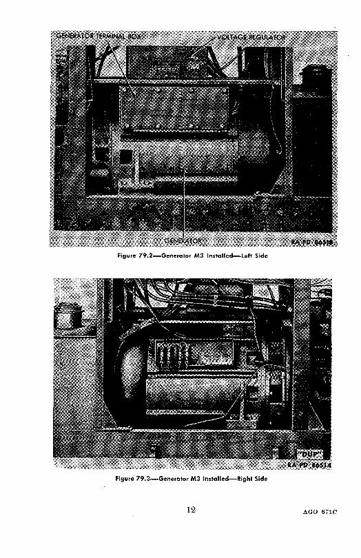
Figure 79.2-Generator M3 Installed-Left Side
Figure 79.3-Generator M3 Installed-Right Side
12 AGO 671C
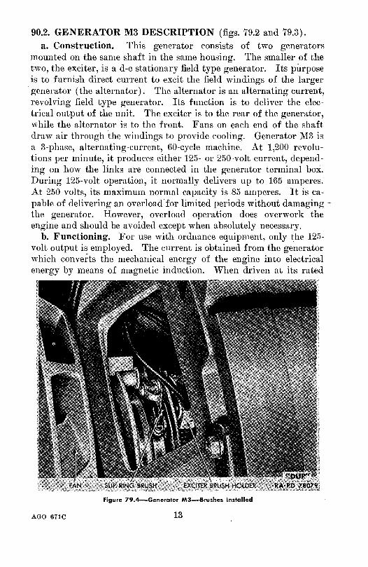
90.2. GENERATOR M3 DESCRIPTION (figs. 79.2 and 79.3).
a. Construction. This generator consists of two generatorsmounted on the same shaft in the same housing. The smaller of thetwo, the exciter, is a d-c stationary field type generator. Its purposeis to furnish direct current to excit the field windings of the largergenerator (the alternator). The alternator is an alternating current,revolving field type generator. Its function is to deliver the elec-trical output of the unit. The exciter is to the rear of the generator,while the alternator is to the front. Fans on each end of the shaftdraw air through the windings to provide cooling. Generator M3 isa 3-phase, alternating-current, 60-cycle machine. At 1,200 revolu-tions per minute, it produces either 125- or 250-volt current, depend-ing on how the links are connected in the generator terminal box.During 125-volt operation, it normally delivers up to 165 amperes.At 250 volts, its maximum normal capacity is 85 amperes. It is ca-pable of delivering an overload'for limited periods without damagingthe generator. However, overload operation does overwork theengine and should be avoided except when absolutely necessary.
b. Functioning. For use with ordnance equipment, only the 125-volt output is employed. The current is obtained from the generatorwhich converts the mechanical energy of the engine into electricalenergy by means of magnetic induction. When driven at its rated
Figure 79.4-Generator M3-Brushes Installed
AGO 671C 13

speed, 1,200 revolutions per minute, the generator produces a voltageat its terminals equivalent to that provided by a usual 125-volt light-ing circuit. This voltage can be varied over a range of 90 to 150 voltsby use of the exciter field rheostat.
90.3. TROUBLE SHOOTING.
a. Commutator Brushes Arc Severely.
Cause Remedy
Dirt on commutator. Clean commutator.Worn brushes. Replace brushes.Brushes stuck in holder. R e m o v e and clean brushes.
Straighten holder if bent.Open circuit in armature coil in Refer to ordnance maintenance
exciter. personnel.
High mica between commutator Refer to ordnance maintenancesegments of exciter. personnel.
b. Fails to Generate Rated Voltage When Output Current Isnormal.
Cause Remedy
Voltage regulator out of adjust- Adjust voltage regulator. (Seement, or defective. par. 90.5c(3).) If adjustment
cannot be made,, refer to ord-nance maintenance personnel.
Exciter commutator dirty. Clean commutator by holding No.00-sandpaper against it. Pulldust from generator with drycompressed air.
Worn commutator brushes. Replace worn brushes.Burned out fuse. Test fuses and replace those which
are burned out.Internal defect in generator. Notify ordnance maintenance per-
sonnel.
c. Fails to Operate at Proper Frequency.
Cause Remedy
Incorrect engine speed. Adjust engine governor for an en-gine speed of 1,200 revolutionsper minute.
14 AGO 671C

d. Generator Delivers No Voltage.
Cause Remedy
Load switch turned off. Turn on load switch.Voltage regulator out of adjust- Adjust voltage regulator. (See
ment. par. 90.5c(3).)Open circuit in generator to field Check generator to rheostat, regu-rheostat to voltage regulator cir- .lator to circuit. Replace brokencuit. wires; tighten loose connections.
Generator commutator dirty. Clean commutator by holding No.00 sandpaper against it. Blowdirt from generator with drycompressed air.
Commutator brushes worn, broken, Inspect commutator brushes. Re-or stuck in holders. place broken or worn brushes.
Clean b r u s h e s which bind.Straighten brush holder if bent.
Fuses burned out. Test fuses and replace those whichare burned out.
Internal defect in generator. Refer to ordnance maintenancepersonnel.
90.4. GENERATOR M3 MAINTENANCE.a. Brush Inspection. At least once every 3 months, remove brush
covers (d below) and visually inspect brushes. (See fig. 79.4.) Ifgummy, or stuck in their holders, remove and clean brushes. Clean alldirt from the brush holders. Check tightness of. all pigtailconnections.
b. Collector Ring Inspection. Inspect collector rings wheneverbrush covers are removed for servicing brushes and brush holders.(To remove covers, see d below.) Note condition of surface of rings.Surface should appear smooth and clean. Scoring or rougheningof collector ring surfaces may be caused by grit or abrasive in brushes,or by presence of oil on rings. Moderately rough collector rings canbe corrected by holding No. C0 class B flintpaper to their surfaces whilethe rings are revolving. If rings are badly scored or worn, report toordnance maintenance personnel. After cleaning collector rings, blowout dirt and grit with compressed air.
c. Commutator Inspection. Inspect exciter commutator wheneverbrush covers are removed. (To remove covers, see d below.) All barsshould appear smooth and clean, and the mica undercut slightly be-
AGO 671C 15

low the surface of the bars. If commutator appears moderately roughor dirty, clean by holding No. 00 class B flintpaper against it whileit is slowly revolving. Badly scored commutators or commutatorswith uneven bars must be reported to ordnance maintenance per-sonnel. Blow out dirt and grit from generator with compressed air.
Note.-Never ues oil or aluminum oxide abrasive cloth on commutators.
d. Brush Removal (fig. 79.4).(1) Disconnect wire attached to trailer brake receptacle.(2) Unscrew nuts and screws securing generator panel to frame
and remove panel.(3) Remove cap screws securing fan guard to generator frame.
Separate fan guard by removing the attaching cap screws and nutsand lift the halves of the guard from the unit.
(4) Using socket head screw wrench, loosen socket head screws,and lift out brush covers.
(5) Remove screws securing brush pigtail connections to brushholders and lift out brushes.
e. Brush installation. When replacing brushes, it is importantthat they are carefully fitted to the commutator or collector rings.To fit brushes, slip a piece of No. 00 class B flintpaper between brushand cummutator or collector ring with flint surface facing brush. Thepaper must be of the same width as the commutator or slip ring. Fol-lowing the curved surface of the commutator or slip ring, move theflintpaper back and forth until the proper brush surface is obtained.Procedure for brush installation is the reverse of d above.
90.5. VOLTAGE REGULATOR M1 (fig. 79.5).
a. Description. A voltage regulator M1 is attached to the under-side of the instrument panel. It is housed in a dust-tight metal box.A spring-loaded lid on the front of the box covers the switch and ad-justment screw. The switch is a toggle type. Its two positions aremarked "MANUAL" and "AUTOMATIC." With the switch on"MANUAL" position, the voltage regulator is removed from the cir-cuit and the generator output must be controlled by hand by meansof the field rheostat. Placing the switch in "AUTOMATIC" positionputs the voltage regulator into the alternator and exciter circuits ofthe generator. The alternator output operates the voltage regulator.The voltage regulator, in turn, regulates the output of the exciter.The exciter output regulates the voltage generated by the alternator.In this manner, the voltage is controlled automatically to within ±2percent. The adjustment screw is provided to raise or lower the volt-
16 AGO 671C

age. Four leads from the back of the voltage regulator box serve toconnect the assembly into the circuit.
b. Trouble Shooting. Caution: If necessary to service voltageregulator while generating unit is in operation, stand on a dry boardand shift voltage from "AUTOMATIC" to "MANUAL" operation.
Figure 79.5 (Added)--Voltage Regulator Adjustment
(1) VOLTAGE VARIES WIDELY FROM DESIRED VOLTAGE.
Cause Remedy
Butterfly valve in throttle box is Replace throttle assembly or referbinding. to ordnance maintenance per-
sonnel for cleaning and lubrica-tion.
'AUTOMATIC - MANUAL" Place "AUTOMATIC" switch inswitch is in "MANUAL" posi- automatic position.tion.
Field rheostat is not completely Turn field rheostat handle all theeliminated from circuit. way in the "increase" direction.
Voltage regulator out of adjust- Check setting of voltage adjustingment. screw.
Internal disorder in voltage regu- Refer to ordnance maintenancelator. personnel.
AGO 671C 17

(2) VOLTAGE FAILS TO BUILD UP.
Cause Remedy'
Commutator or brushes dirty or Inspect commutator and brushes;worn. clean, repair, or replace as nec-
essary.Exciter driving belt loose (M7A1 Adjust exciter driving belt.
unit only).Open circuit in field rheostat or in Repair or replace broken or dis-
wiring to rheostat. connected wires.Voltage regulator out of adjust- Check setting of voltage adjusting
ment. screw.Internal defect in voltage regu- Refer to ordnance maintenance
lator. personnel.
(3) VOLTAGE BECOMES ERRATIC.
Cause Remedy
Loose connections in wiring to Check all connections for tightnessvoltage regulator or elsewhere and freedom from corrosion.in generating circuit.
Internal defect in voltage regu- Refer to ordnance maintenancelator. personnel.
(4) VOLTAGE REGULATION IS POOR.
Cause Remedy
Field rheostat is not entirely elim- Turn field rheostat handle as farinated from circuit. as it- will go in the "increase"
direction.Loose connection in circuit to volt- Check wiring to regulator and
age regulator. tighten all loose connections.Internal defect in voltage regu- Refer to ordnance maintenance
]ator. personnel.
(5) VOLTAGE DROPS EXCESSIVELY UPON APPLICATION OF HEAVY LOAD.
Cause Remedy
"AUTOMATIC - MANUAL" Place "AUTOMATIC" switch inswitch is in "MANUAL" posi- "AUTOMATIC" position.tion.
Field rheostat not entirely elimi- Turn field rheostat handle as farnated from circuit. as it will go in the "increase"
direction.Internal defect in voltage regu- Refer to ordnance maintenance
lator. personnel.
18 AGO 671C

c. Adjustment (fig. 79.5).(1) Set the main power switch in "OFF" position. Start the gen-
erating unit and allow it to warm up. Turn the field rheostat handleall the way to short out all rheostat resistance. In this position thevoltage would be at its maximum if the voltage regulator were not inservice.
(2) Place' the "AUTOMATIC-MANUAL" switch on the' frontpanel of the voltage regulator in "AUTOMATIC" position.
(3) Adjust the output voltage to desired amount (normally 125volts) by turning adjustment screw marked "TO RAISE VOLT-AGE."
Note. It is not necessary to switch the "AUTOMATIC-MANUAL" switch from"AUTOMATIC" to "MANUAL," or vice versa, when starting or stopping theunit. [he voltage regulator automatically starts and stops with the generator,and may be left either in service or out of service.
d. Maintenance. Keep regulator mounting screws tight at alltimes. Inspect wiring in circuit to voltage regulator at frequent inter-vals to see if the insulation is in good condition and all connectionsale tight. Do not permit grease or oil to seep into regulator:
90.6. POWER RECEPTACLES (fig. 79).Generating unit M15A1 is equipped with power receptacles identicalto those used on generating units M7 and M7AL. Description andmaintenance are given in paragraphs 89 and 90.
91. INSTRUMENT PANEL (figs. 8, 60.1, 80 and 82).
* * * * * * *
Figure 80-Instrument Panel-U. S. M. Co.-Generating Unit M7
-Figure 82-Instrument Panel-Generating Unit M7-Rear View
96.1 FREQUENCY METER (Added).The frequency meter is located to the left of the voltmeter on the in-strument panel. It is a vibrating reed type instrument and registersthe number of cycles per second at which the current is alternating.Its range is from 57 to 63 cycles.
114. FUSE BLOCK (fig. 89).Twodouble-fuse * * * instrument panel apron. On generatingunit M15A, 25-ampere fuses are attached to a bracket belowthe tool box and battery or below the instrument panel.
* * * * * *
[AG 300.7 (5 May 45)]
'AGO 671C 19

BY ORDER OF THE SECRETARY OF WAR:
OFFICIAL: G. C. MARSHALLEDWARD F. WITSELL Chief of StaffMajor GeneralActing The Adjutant General
DISTRIBUTION:
AAF (10); AGF (5); ASF (2); Dept (10); AAF Comd (2);Arm & Sv Bd (1); S Div ASF (1); Tech Sv (2); SvC(10); PC&S (1); PE, 9 (5); Dist 0, 9 (5); Dist Br 0,9 (3); Reg 0, 9 (3); Establishmlent, 9 (5); DecentralizedSub-0, 9 (3) ; Gen &Sp Sv Sch (10) ;USMIA (20) ;A (10);CHQ (10); D (2); AF (2); T/O & E 9-7 (3); 9-9 (3);9-57 (3); 9-65 (2); 9-67 (3); 9-76 (2); 9-318 (3); 9-377(3); 44-115 (2); 44-117 (3).
Refer-to FM 21-6 for explanation of distribution formula.
20 AGO 671CU.S. GOVERNMENT PRINTING OFFICE: 1945