generator eu20i - honda
TRANSCRIPT

GENERATOR
OWNER'S MANUAL
MANUEL DE L'UTILISATEUR
BEDIENUNGSANLEITUNG
MANUAL DE EXPLICACIONES
EU20i
OWNER’S MANUAL
MANUEL DE L’UTILISATEUR
BEDIENUNGSANLEITUNG
MANUAL DE EXPLICACIONES
Honda EU20i
Original instructions
Notice originale
Originalbetriebsanleitung
Manual original
The‘‘e-SPEC’’mark symbolizes environmentallyresponsible technologies applied to Honda powerequipment, which contains our wish to ‘‘preservenature for generations to come.’’

1
Indicates a strong possibility of severe personal injury ordeath if instructions are not followed.
Indicates a possibility of personal injury or equipmentdamage if instructions are not followed.
Honda generator is designed to give safe and dependable service ifoperated according to instructions. Read and understand the Owner’sManual before operating the generator. Failure to do so could resultin personal injury or equipment damage.
Thank you for purchasing a Honda generator.
All information in this publication is based on the latest productinformation available at the time of approval for printing.
Honda Motor Co., Ltd. reserves the right to make changes at any timewithout notice and without incurring any obligation.
No part of this publication may be reproduced without writtenpermission.
This manual should be considered a permanent part of the generatorand should remain with it if it is resold.
Pay special attention to statements preceded by the following words:
Gives helpful information.
If a problem should arise, or if you have any questions about thegenerator, consult an authorized Honda dealer.
The illustration may vary according to the type.
This manual covers operation and maintenance of the EU20i generator.

2
CONTENTS
..................................................................SAFETY INSTRUCTIONS . 3............................................................SAFETY LABEL LOCATIONS . 7
.................................................CE mark and noise label locations . 11.....................................................COMPONENT IDENTIFICATION . 12
................................................................PRE-OPERATION CHECK . 16.................................................................STARTING THE ENGINE . 21
Carburetor Modification for High Altitude Operation...........................................................................GENERATOR USE . 25
.................................................................STOPPING THE ENGINE . 37...............................................................................MAINTENANCE . 39
...........................................................TRANSPORTING/STORAGE . 44......................................................................TROUBLESHOOTING . 47
.............................................................................SPECIFICATIONS . 50..........................................................................WIRING DIAGRAM . 52
1.2.
3.4.5.
6.7.8.9.
10.11.12.
...............MAJOR Honda DISTRIBUTOR ADDRESSES . Inside back cover.......‘‘ ’’ CONTENT OUTLINE . Inside back coverEC Declaration of Conformity
3
SAFETY INSTRUCTIONS1.
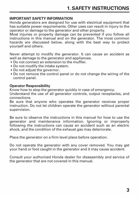
IMPORTANT SAFETY INFORMATION
Operator Responsibility
Honda generators are designed for use with electrical equipment thathas suitable power requirements. Other uses can result in injury to theoperator or damage to the generator and other property.Most injuries or property damage can be prevented if you follow allinstructions in this manual and on the generator. The most commonhazards are discussed below, along with the best way to protectyourself and others.
Never attempt to modify the generator. It can cause an accident aswell as damage to the generator and appliances.
Do not connect an extension to the muffler.Do not modify the intake system.Do not adjust the governor.Do not remove the control panel or do not change the wiring of thecontrol panel.
Know how to stop the generator quickly in case of emergency.Understand the use of all generator controls, output receptacles, andconnections.Be sure that anyone who operates the generator receives properinstruction. Do not let children operate the generator without parentalsupervision.
Do not operate the generator with any cover removed. You may getyour hand or foot caught in the generator and it may cause accident.
Place the generator on a firm level place before operation.
Consult your authorized Honda dealer for disassembly and service ofthe generator that are not covered in this manual.
Be sure to observe the instructions in this manual for how to use thegenerator and maintenance information. Ignoring or improperlyfollowing the instructions can cause an accident such as an electricshock, and the condition of the exhaust gas may deteriorate.
4
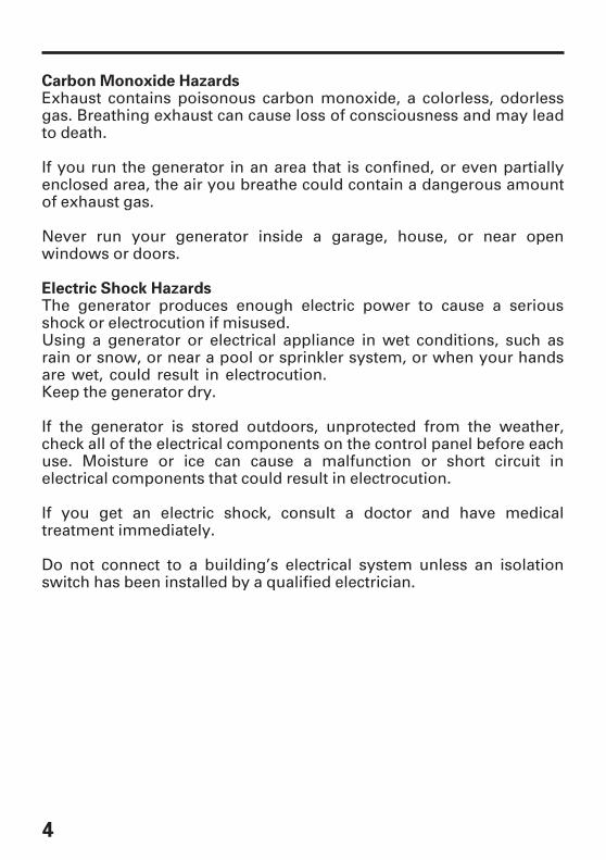
Carbon Monoxide Hazards
Electric Shock Hazards
Exhaust contains poisonous carbon monoxide, a colorless, odorlessgas. Breathing exhaust can cause loss of consciousness and may leadto death.
If you run the generator in an area that is confined, or even partiallyenclosed area, the air you breathe could contain a dangerous amountof exhaust gas.
Never run your generator inside a garage, house, or near openwindows or doors.
The generator produces enough electric power to cause a seriousshock or electrocution if misused.Using a generator or electrical appliance in wet conditions, such asrain or snow, or near a pool or sprinkler system, or when your handsare wet, could result in electrocution.Keep the generator dry.
If the generator is stored outdoors, unprotected from the weather,check all of the electrical components on the control panel before eachuse. Moisture or ice can cause a malfunction or short circuit inelectrical components that could result in electrocution.
If you get an electric shock, consult a doctor and have medicaltreatment immediately.
Do not connect to a building’s electrical system unless an isolationswitch has been installed by a qualified electrician.

-
--
5
Fire and Burn Hazards
Refuel With Care
Do not use the generator in areas with a high risk of fire.
When installed in ventilated rooms, additional requirements for fireand explosion protection shall be observed.
The exhaust system gets hot enough to ignite some materials.Keep the generator at least 1 meter (3 feet) away from buildings andother equipment during operation.Do not enclose the generator in any structure.Keep flammable materials away from the generator.
Some parts of the internal combustion engine are hot and may causeburns. Pay attention to the warnings on the generator.
The muffler becomes very hot during operation and remains hot for awhile after stopping the engine. Be careful not to touch the mufflerwhile it is hot. Let the engine cool before storing the generator indoors.
Do not pour the water directly on the generator to put out the firewhen it occurs. Use an appropriate fire extinguisher speciallydesigned for electric fire or oil fire.
If you inhale fumes produced by an accidental fire with the generator,consult a doctor and have medical treatment immediately.
Gasoline is extremely flammable, and gasoline vapor can explode.Allow the engine to cool if the generator has been in operation.
Refuel only outdoors in a well ventilated area with the engine off.
Do not overfill the fuel tank.
Never smoke near gasoline, and keep other flames and sparks away.
Always store gasoline in an approved container.
Make sure that any spilled fuel has been wiped up before starting theengine.
6
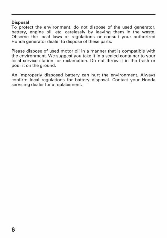
DisposalTo protect the environment, do not dispose of the used generator,battery, engine oil, etc. carelessly by leaving them in the waste.Observe the local laws or regulations or consult your authorizedHonda generator dealer to dispose of these parts.
Please dispose of used motor oil in a manner that is compatible withthe environment. We suggest you take it in a sealed container to yourlocal service station for reclamation. Do not throw it in the trash orpour it on the ground.
An improperly disposed battery can hurt the environment. Alwaysconfirm local regulations for battery disposal. Contact your Hondaservicing dealer for a replacement.

7
SAFETY LABEL LOCATIONS2.
[For European model: G, GP3, GW, B, F, W types]
HOT CAUTION
SOCKET CAUTION
READ OWNER’S MANUAL
EXHAUST CAUTION
FUEL CAUTION
CONNECT CAUTION
These labels warn you of potential hazards that can cause seriousinjury. Read the labels and safety notes and precautions described inthis manual carefully.
If a label comes off or becomes hard to read, contact your Hondadealer for a replacement.
8
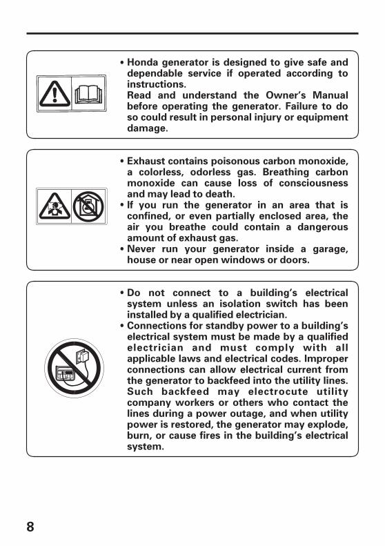
Honda generator is designed to give safe anddependable service if operated according toinstructions.Read and understand the Owner’s Manualbefore operating the generator. Failure to doso could result in personal injury or equipmentdamage.
Exhaust contains poisonous carbon monoxide,a colorless, odorless gas. Breathing carbonmonoxide can cause loss of consciousnessand may lead to death.If you run the generator in an area that isconfined, or even partially enclosed area, theair you breathe could contain a dangerousamount of exhaust gas.Never run your generator inside a garage,house or near open windows or doors.
Connections for standby power to a building’selectrical system must be made by a qualifiedelectrician and must comply with allapplicable laws and electrical codes. Improperconnections can allow electrical current fromthe generator to backfeed into the utility lines.Such backfeed may electrocute utilitycompany workers or others who contact thelines during a power outage, and when utilitypower is restored, the generator may explode,burn, or cause fires in the building’s electricalsystem.
Do not connect to a building’s electricalsystem unless an isolation switch has beeninstalled by a qualified electrician.
9
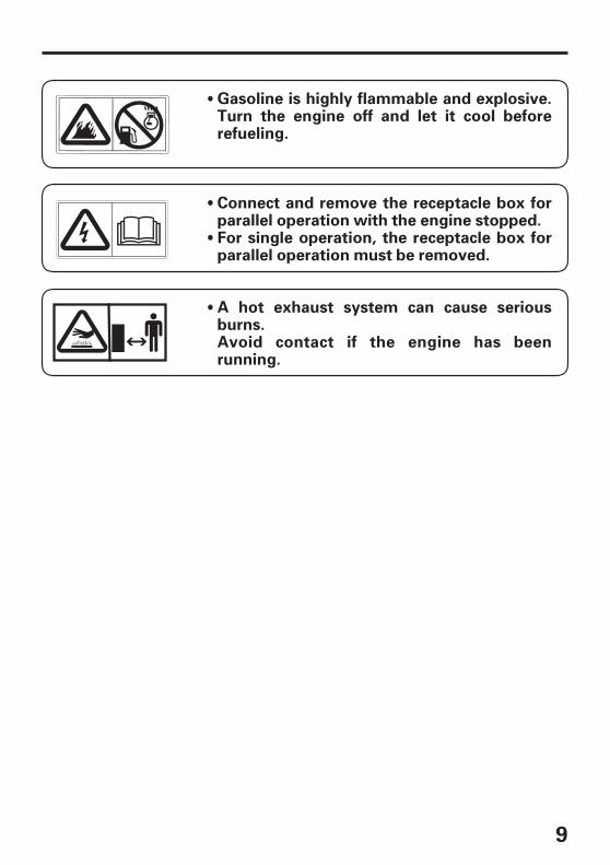
Gasoline is highly flammable and explosive.Turn the engine off and let it cool beforerefueling.
Connect and remove the receptacle box forparallel operation with the engine stopped.For single operation, the receptacle box forparallel operation must be removed.
A hot exhaust system can cause seriousburns.Avoid contact if the engine has beenrunning.
10
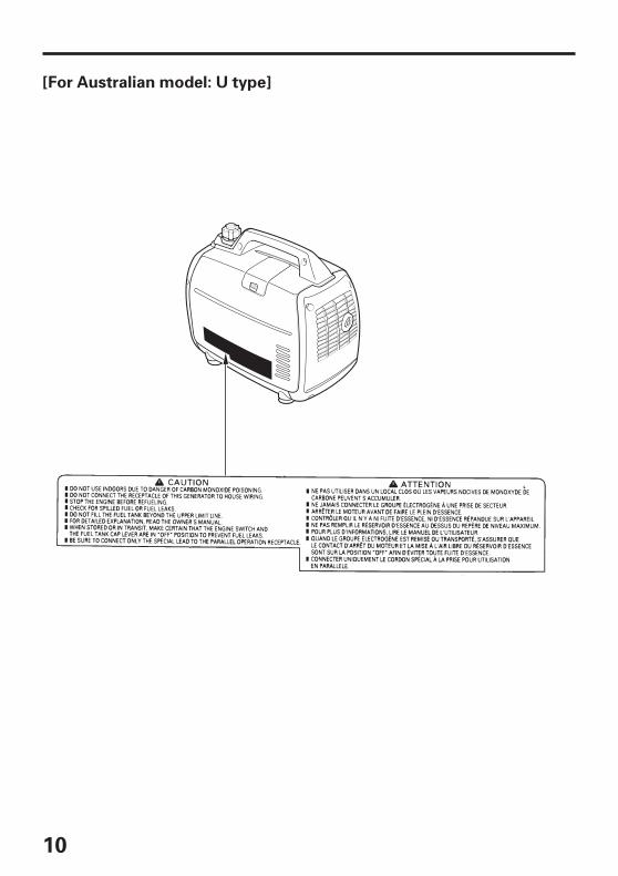
[For Australian model: U type]
11
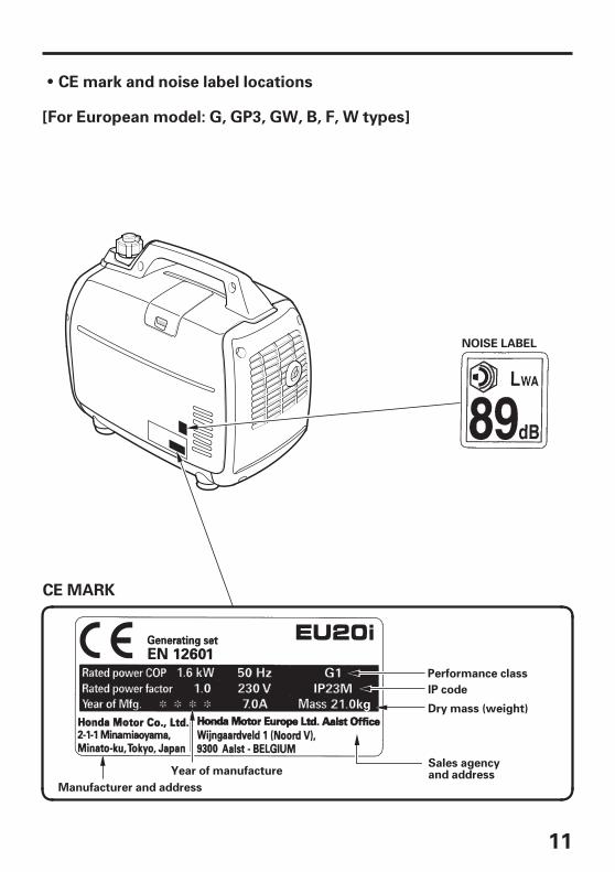
NOISE LABEL
Manufacturer and address
Performance class
Year of manufacture
Dry mass (weight)
Sales agencyand address
IP code
CE mark and noise label locations
[For European model: G, GP3, GW, B, F, W types]
CE MARK

12
COMPONENT IDENTIFICATION3.
CHOKE LEVER
FUEL CAP VENT LEVER
FUEL FILLER CAP
CONTROL PANEL
FRAME SERIAL NUMBER
ENGINE SWITCH
MUFFLER
SPARK PLUGMAINTENANCE COVER
STARTER GRIP
MAINTENANCE COVER
Record the frame serial number in the space below. You will need thisserial number when ordering parts.
Frame serial number:
13
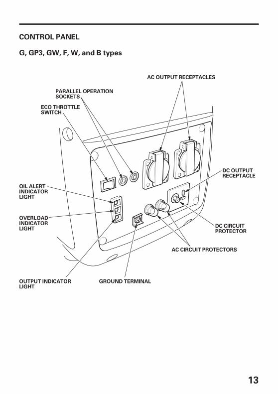
CONTROL PANEL
G, GP3, GW, F, W, and B types
GROUND TERMINAL
PARALLEL OPERATIONSOCKETS
AC OUTPUT RECEPTACLES
OIL ALERTINDICATORLIGHT
OVERLOADINDICATORLIGHT
OUTPUT INDICATORLIGHT
AC CIRCUIT PROTECTORS
DC CIRCUITPROTECTOR
DC OUTPUTRECEPTACLE
ECO THROTTLESWITCH
14
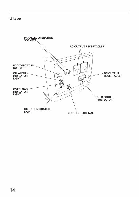
U type
AC OUTPUT RECEPTACLES
PARALLEL OPERATIONSOCKETS
ECO THROTTLESWITCH
OIL ALERTINDICATORLIGHT
OVERLOADINDICATORLIGHT
GROUND TERMINAL
OUTPUT INDICATORLIGHT
DC CIRCUITPROTECTOR
DC OUTPUTRECEPTACLE
15
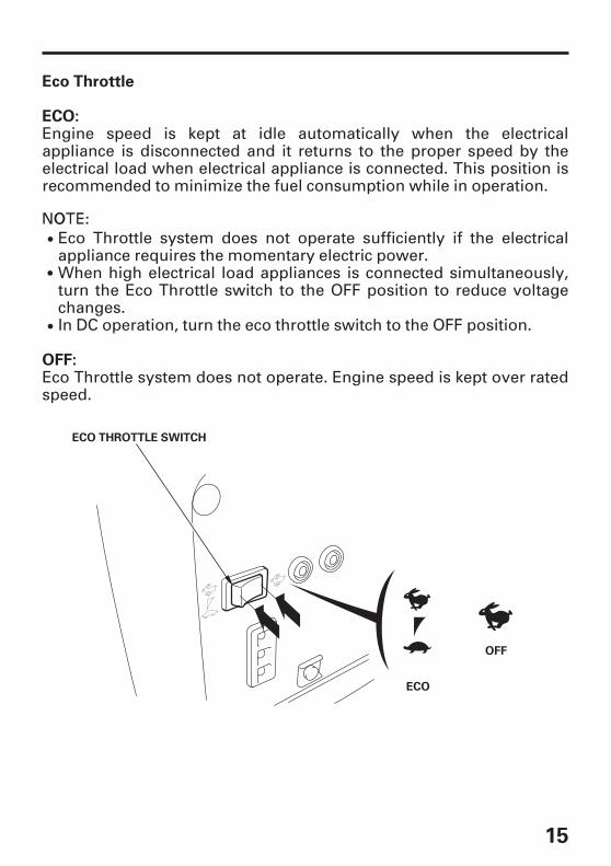
Eco Throttle
ECO:
OFF:
OFF
ECO THROTTLE SWITCH
ECO
Engine speed is kept at idle automatically when the electricalappliance is disconnected and it returns to the proper speed by theelectrical load when electrical appliance is connected. This position isrecommended to minimize the fuel consumption while in operation.
Eco Throttle system does not operate. Engine speed is kept over ratedspeed.
Eco Throttle system does not operate sufficiently if the electricalappliance requires the momentary electric power.
In DC operation, turn the eco throttle switch to the OFF position.
When high electrical load appliances is connected simultaneously,turn the Eco Throttle switch to the OFF position to reduce voltagechanges.

-
16
PRE-OPERATION CHECK4.
Be sure to check the generator on a level surface with the enginestopped.
Using non detergent oil or 2-stroke engine oil could shorten theengine’s service life.
Recommended oil
AMBIENT TEMPERATURE
Check the engine oil level.
Use 4-stroke motor oil that meets or exceeds the requirements for APIservice category SE or later (or equivalent). Always check the APIservice label on the oil container to be sure it includes the letters SE orlater (or equivalent).
SAE 10W 30 is recommended for general use. Other viscositiesshown in the chart may be used when the average temperature inyour area is within the recommended range.
1.

17
Running the engine with insufficient oil can cause serious enginedamage.
OIL FILLER CAP
DIPSTICK OIL FILLER HOLE
MAINTENANCE COVER SCREW
MAINTENANCE COVER
UPPER LEVEL
The Oil Alert system will automatically stop the engine before the oillevel falls below the safe limit. However, to avoid the inconvenience ofan unexpected shutdown, it is still advisable to visually inspect the oillevel regularly.
Loosen the maintenance cover screw and remove the maintenancecover.
If the oil level is below the end of the dipstick, refill with recommendedoil up to the top of the oil filler neck.
Remove the oil filler cap, and wipe the dipstick with a clean rag. Checkthe oil level by inserting the dipstick in the oil filler hole withoutscrewing it in.

18
Avoid repeated or prolonged contact with skin or breathing ofvapor.KEEP OUT OF REACH OF CHILDREN.
Be careful not to spill fuel when refueling. Spilled fuel or fuel vapormay ignite. If any fuel is spilled, make sure the area is dry beforestarting the engine.
Do not overfill the fuel tank (there should be no fuel above theupper limit mark). After refueling, make sure the fuel filler cap isclosed properly and securely.
Refuel in a well ventilated area with the engine stopped. Do notsmoke or allow flames or sparks in the area where the engine isrefueled or where gasoline is stored.
Gasoline is extremely flammable and is explosive under certainconditions.
FUEL FILLER CAP
OPEN
UPPER LIMIT MARK
Check the fuel level.
If the fuel level is low, refuel the fuel tank until the level as specified.After refueling, tighten the fuel filler cap securely.
Never use stale or contaminated gasoline or an oil/gasoline mixture.Avoid getting dirt or water in the fuel tank.
Use automotive unleaded gasoline with a Research Octane Number of91 or higher (a Pump Octane Number of 86 or higher).
2.

19
Gasolines Containing Alcohol
Gasoline spoils very quickly depending on factors such as lightexposure, temperature and time.In worst cases, gasoline can be contaminated within 30 days.Using contaminated gasoline can seriously damage the engine(carburetor clogged, valve stuck).Such damage due to spoiled fuel is disallowed from coverage by thewarranty.To avoid this please strictly follow these recommendations:
If you notice any undesirable operating symptoms while using agasoline that contains alcohol, or one that you think containsalcohol, switch to a gasoline that you know does not contain alcohol.
Before buying fuel from an unfamiliar station, try to find out if thefuel contains alcohol, if it does, confirm the type and percentage ofalcohol used.
Honda cannot endorse the use of fuels containing methanol sinceevidence of their suitability is as yet incomplete.
Fuel system damage or engine performance problems resultingfrom the use of fuels that contain alcohol is not covered under thewarranty.
Do not use gasohol that contains more than 10% ethanol. Do not usegasoline containing methanol (methyl or wood alcohol) that does notalso contain cosolvents and corrosion inhibitors for methanol. Neveruse gasoline containing more than 5% methanol, even if it hascosolvents and corrosion inhibitors.
If you decide to use a gasoline containing alcohol (gasohol), be sure itsoctane rating is at least as high as that recommended by Honda. Thereare two types of ‘‘gasohol’’: one containing ethanol, and the othercontaining methanol.
To slow deterioration, keep gasoline in a certified fuel container.
Only use specified gasoline (see page ).Use fresh and clean gasoline.
If long storage (more than 30 days) is foreseen, drain fuel tank andcarburetor (see page ).
18
45

20
Never run the engine without the air cleaner elements. Rapid enginewear will result from contaminants, such as dust and dirt, beingdrawn through the carburetor, into the engine.
AIR CLEANER BODY
AIR CLEANER COVER
MAINTENANCE COVER
AIR CLEANER ELEMENTS
MAINTENANCE COVER SCREW
Check the air cleaner.
Check the air cleaner elements to be sure they are clean and in goodcondition.Loosen the maintenance cover screw and remove the maintenancecover. Press the latch tab on the top of the air cleaner body, removethe air cleaner cover, check the elements.Clean or replace the elements if necessary (see page ).
3.
41

21
STARTING THE ENGINE5.
FUEL CAP VENT LEVER
OONN
ON
ENGINE SWITCH
OONN
ON
Before starting the engine disconnect any load from the AC receptacle.
Turn the engine switch to the ON position.
Turn the fuel cap lever fully clockwise to the ON position.
Turn the fuel tank cap vent lever to the OFF position whentransporting the generator.
1.
2.

22
Do not allow the starter grip to snap back. Return it slowly byhand.
The starter grip can be drawn back very quickly before yourelease it. This may pull your hand forcefully toward the engineand cause an injury.
CLOSED
CLOSED
STARTER GRIP
CHOKE LEVER
DDiirreeccttiioonn ttoo ppuullll
Do not use the choke when the engine is warm or the airtemperature is high.
Move the choke lever to the CLOSED position.
Pull the starter grip lightly until you feel resistance, then pull thestarter grip briskly toward in the direction of the arrow as shownbelow.
3.
4.

23
OPEN
CHOKE LEVER
OOPPEENN
Move the choke lever to the OPEN position as the engine warms up.
If the engine stops and will not restart, check the engine oil level (seepage ) before troubleshooting in other areas.
5.
17

24
Carburetor Modification for High Altitude Operation
Operation of the generator at an altitude lower than the carburetor isjetted for may result in reduced performance, overheating, andserious engine damage caused by an excessively lean air/fuel mixture.
High altitude performance can be improved by specific modificationsto the carburetor. If you always operate your generator at altitudesabove 1,500 meters (5,000 feet), have your authorized Honda servicingdealer perform this carburetor modification. This engine, whenoperated at high altitude with the carburetor modifications for highaltitude use, will meet each emission standard throughout its usefullife.
Even with carburetor modification, engine horsepower will decreaseabout 3.5% for each 300-meter (1,000-foot) increase in altitude. The ef-fect of altitude on horsepower will be greater than this if no carburetormodification is made.
At high altitude, the standard carburetor air-fuel mixture will be toorich. Performance will decrease, and fuel consumption will increase. Avery rich mixture will also foul the spark plug and cause hard starting.Operation at an altitude that differs from that at which this engine wascertified, for extended periods of time, may increase emissions.

25
GENERATOR USE6.
Do not connect to a building’s electrical system unless an isolationswitch has been installed by a qualified electrician.Connections for standby power to a building’s electrical systemmust be made by a qualified electrician and must comply with allapplicable laws and electrical codes. Improper connections canallow electrical current from the generator to back feed into theutility lines. Such back feed may electrocute utility companyworkers or others who contact the lines during a power outage,and when utility power is restored, the generator may explode,burn, or cause fires in the building’s electrical system.
GROUND TERMINAL
Be sure to ground the generator when the connected equipment isgrounded.
26
Do not exceed the current limit specified for any one receptacle.Do not connect the generator to a household circuit. This couldcause the damage to the generator or to electrical appliances in thehouse.Do not modify or use the generator for other purposes than it isintended for. Also observe the following when using the generator.Do not connect an extension to the exhaust pipe.When an extension cable is required, be sure to use a tough rubbersheathed flexible cable (IEC 245 or equivalent).Limit length of extension cables; 60 m (200 feet) for cables of 1.5mm (0.0023 in ) and 100 m (330 feet) for cables of 2.5 mm (0.0039in ). Long extension cables will lower usable power due toresistance in the extension cable.Keep the generator away from other electric cables or wires such ascommercial power supply lines.
The DC receptacle can be used while the AC power is in use.If you use both at the same time, do not exceed the maximum ACpower.Maximum AC power:Most appliance motors require more than their rated wattage forstartup.Make sure the electrical rating of the tool or appliance does notexceed that of the generator. Never exceed the maximum powerrating of the generator. Power levels between rated and maximummay be used for no more than 30 minutes.Substantial overloading will switch OFF the AC circuit protector(Except U type). Exceeding the time limit for maximum poweroperation or slightly overloading the generator may not switch theAC circuit protector OFF, but will shorten the service life of thegenerator.Limit operation requiring maximum power to 30 minutes.Maximum power is:For continuous operation, do not exceed the rated power.Rated power is:In either case, the total power requirements (VA) of all appliancesconnected must be considered.
1.5 kVA
2.0 kVA
1.6 kVA

27
AC applications
Substantial overloading that continuously lights the Overloadindicator (red) may damage the generator. Marginal overloadingthat temporarily lights the Overload indicator (red) may shorten theservice life of the generator.Be sure that all appliances are in good working order beforeconnecting them to the generator. Electrical equipment (includinglines and plug connections) should not be defective. If an appliancebegins to operate abnormally, becomes sluggish, or stops suddenly,turn off the generator engine switch immediately. Then disconnectthe appliance, and examine it for signs of malfunction.
OUTPUT INDICATORLIGHT (GREEN)
OVERLOAD INDICATORLIGHT (RED)
Confirm that the appliance to be used is switched off, and plug in theappliance.
Start the engine and make sure the Output indicator (green) comeson.
1.
2.

28
AC Circuit Protector (B, F, G, GP3, GW and W types)
AC RECEPTACLE No. 1 AC RECEPTACLE No. 2
CIRCUIT PROTECTOR(For receptacle No. 1)
CIRCUIT PROTECTOR(For receptacle No. 2)
ON
OFF
The AC circuit protectors will automatically switch OFF (push buttoncomes out) if there is a short circuit or a significant overload of thegenerator at receptacle.If an AC circuit protector switches OFF automatically, check that theappliance is working properly and does not exceed the rated loadcapacity of the circuit before resetting the AC circuit protector ON(pushing the push button in).

29
Output and Overload Indicators
OUTPUT INDICATORLIGHT (GREEN)
OVERLOAD INDICATORLIGHT (RED)
The Output indicator (green) will remain on during normal operatingconditions.
Stop the engine if the Overload indicator (red) comes on andinvestigate the overload source.
Before connecting an appliance to the generator, check that it is ingood order, and that its electrical rating does not exceed that of thegenerator. Then connect the power cord of the appliance, and startthe engine.
When an electric motor is started, both the Overload indicator (red)and the Output indicator (green) may come on simultaneously. This isnormal if the Overload indicator (red) goes off after about 4 seconds. Ifthe Overload indicator (red) stays on, consult your Honda generatordealer.
If the generator is overloaded (see page ), or if there is a short in theconnected appliance, the Output indicator (green) will go off, theOverload indicator (red) will come on and current to the connectedappliance will be shut off.
26
30
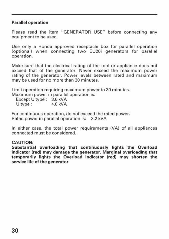
Parallel operation
Substantial overloading that continuously lights the Overloadindicator (red) may damage the generator. Marginal overloading thattemporarily lights the Overload indicator (red) may shorten theservice life of the generator.
Please read the item ‘‘GENERATOR USE’’ before connecting anyequipment to be used.
Use only a Honda approved receptacle box for parallel operation(optional) when connecting two EU20i generators for paralleloperation.
Make sure that the electrical rating of the tool or appliance does notexceed that of the generator. Never exceed the maximum powerrating of the generator. Power levels between rated and maximummay be used for no more than 30 minutes.
Limit operation requiring maximum power to 30 minutes.Maximum power in parallel operation is:
For continuous operation, do not exceed the rated power.Rated power in parallel operation is:
In either case, the total power requirements (VA) of all appliancesconnected must be considered.
3.6 kVA4.0 kVA
3.2 kVA
Except U type :U type :
31
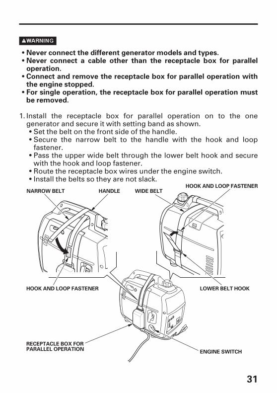
Never connect the different generator models and types.Never connect a cable other than the receptacle box for paralleloperation.Connect and remove the receptacle box for parallel operation withthe engine stopped.For single operation, the receptacle box for parallel operation mustbe removed.
RECEPTACLE BOX FORPARALLEL OPERATION
HANDLE WIDE BELT
LOWER BELT HOOK
ENGINE SWITCH
NARROW BELTHOOK AND LOOP FASTENER
HOOK AND LOOP FASTENER
Install the receptacle box for parallel operation on to the onegenerator and secure it with setting band as shown.
Set the belt on the front side of the handle.Secure the narrow belt to the handle with the hook and loopfastener.
Install the belts so they are not slack.Route the receptacle box wires under the engine switch.
Pass the upper wide belt through the lower belt hook and securewith the hook and loop fastener.
1.

32
At least 1 m (3 feet)
BAND
GROUNDTERMINAL
CABLECONNECTORS
Connect the cable connectors and ground terminals of thereceptacle box for parallel operation to the generators and securethe cord clamp to handle.
Place two generators at least 1 meter (3 feet) away from eachother during parallel operation.Route the wire through the handle and clamp it to the handleusing the band.Take care not to slacken the wire toward the starter grip side.Connect the longer wire to the generator on which the receptaclebox for parallel operation is not installed.Do not set the generators with the exhaust side face to face eachother.
Connect the ground terminal of one generator to the ground.When an appliance is connected to the ground, connect thegenerator to the ground as well.
2.
3.

33
AC Circuit Protector (Except U type)
OUTPUT INDICATORLIGHT (GREEN)
RECEPTACLE BOX FORPARALLEL OPERATION
AC CIRCUITPROTECTOR
OFF
ON
Start the engines and make sure the Output indicators (green) comeon.
Confirm that the appliance to be used is switched off, and plug in theappliance.
Switch on the equipment to be used.
The AC circuit protector on the receptacle box for parallel operationwill automatically switch OFF (push button comes out) if there is ashort circuit or a significant overload of the generator at receptacle.If an AC circuit protector switches OFF automatically, check that theappliance is working properly and does not exceed the rated loadcapacity (16A) of the circuit before resetting the AC circuit protectorON (pushing the push button in).
5.
4.
6.

34
To prevent the possibility of creating a spark near the battery,connect charging cable first to the generator, then to the battery.Disconnect cable first at the battery.Before connecting charging cable to a battery that is installed in avehicle, disconnect the vehicle’s battery cable. Reconnect thevehicle’s battery cable after the charging cables are removed. Thisprocedure will prevent the possibility of a short circuit and sparks ifyou make accidental contact between a battery terminal and thevehicle’s frame or body.
Do not attempt to start an automobile engine with the generatorstill connected to the battery. The generator may be damaged.Connect the positive battery terminal to the positive charging cord.Do not reverse the charging cables, or serious damage to thegenerator and/or battery may occur.
DC application
CHARGING CABLE(SOLD SEPARATELY: G, GP3, GW, B, F, W types)
Connect the charging cable to the DC receptacle of the generatorand then to the battery terminals.
The DC receptacle may be used for charging 12 volt automotive-typebatteries only.
In DC operation, turn the Eco Throttle switch to the OFF position.
1.
--
35
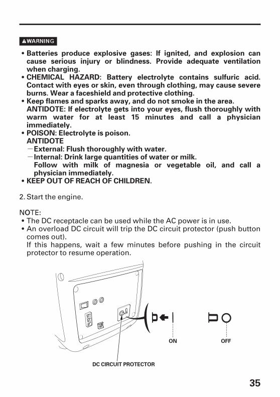
Batteries produce explosive gases: If ignited, and explosion cancause serious injury or blindness. Provide adequate ventilationwhen charging.
Keep flames and sparks away, and do not smoke in the area.ANTIDOTE: If electrolyte gets into your eyes, flush thoroughly withwarm water for at least 15 minutes and call a physicianimmediately.POISON: Electrolyte is poison.ANTIDOTE
KEEP OUT OF REACH OF CHILDREN.
External: Flush thoroughly with water.Internal: Drink large quantities of water or milk.Follow with milk of magnesia or vegetable oil, and call aphysician immediately.
CHEMICAL HAZARD: Battery electrolyte contains sulfuric acid.Contact with eyes or skin, even through clothing, may cause severeburns. Wear a faceshield and protective clothing.
DC CIRCUIT PROTECTOR
ON OFF
Start the engine.
The DC receptacle can be used while the AC power is in use.An overload DC circuit will trip the DC circuit protector (push buttoncomes out).If this happens, wait a few minutes before pushing in the circuitprotector to resume operation.
2.

36
Oil Alert system
OIL ALERT INDICATORLIGHT (RED)
The Oil Alert system is designed to prevent engine damage caused byan insufficient amount of oil in the crankcase. Before the oil level in thecrankcase falls below a safe limit, the Oil Alert system willautomatically shut down the engine (the engine switch will remain inthe ON position).
If the Oil Alert system shuts down the engine, the Oil Alert indicator(red) will come on when you operate the starter, and the engine willnot run. If this occurs, check the engine oil level (see page ).17
37
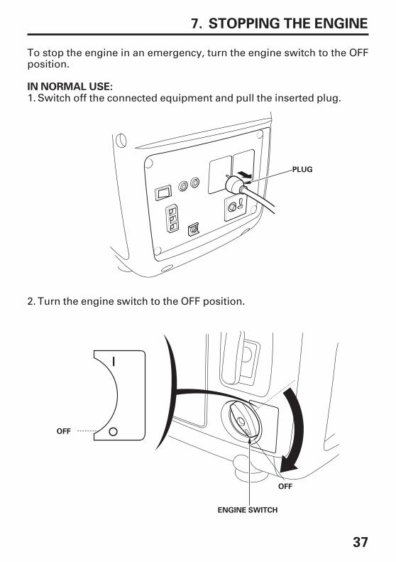
STOPPING THE ENGINE7.
IN NORMAL USE:
OFF
ENGINE SWITCH
OFF
PLUG
To stop the engine in an emergency, turn the engine switch to the OFFposition.
Switch off the connected equipment and pull the inserted plug.
Turn the engine switch to the OFF position.
1.
2.

38
Be sure the fuel cap vent lever and the engine switch are in the OFFposition when stopping, transporting and/or storing the generator.
OFFFUEL CAP VENT LEVER
OOFFFF
RECEPTACLE BOX FORPARALLEL OPERATION(SOLD SEPARATELY)
When parallel operation has been executed, pull the receptacle boxfor parallel operation.
Turn the fuel cap vent lever fully counterclockwise to the OFFposition.
3.
4.

39
MAINTENANCE8.
Maintenance Schedule
Use Honda Genuine parts or their equivalent. The use of replacementparts which are not of equivalent quality may damage the generator.
Make sure the engine is off before you begin any maintenance orrepairs. This will eliminate several potential hazards:
Carbon monoxide poisoning from engine exhaust. Be sure there isadequate ventilation whenever you operate the engine.Burns from hot parts. Let the engine and exhaust system coolbefore touching.Injury from moving parts. Do not run the engine unless instructedto do so.
The muffler becomes very hot during operation and remains hot for awhile after stopping the engine. Be careful not to touch the mufflerwhile it is hot. Let the engine cool before maintenance.
The purpose of the maintenance and adjustment schedule is to keepthe generator in the best operating condition.Inspect or service as scheduled in the table below.
Performed at every indicatedmonth or operating hour interval,whichever comes first.
ITEMREGULAR SERVICE PERIOD (3) Each use First
monthor
20 hrs.
Every3 months
or50 hrs.
(1)
Engine oil
Air cleaner
Spark plug
Valve ClearanceCombustionchamberFuel tank & filterFuel line
Every6 months
or100 hrs.
(2)
Everyyears
or200 hrs.
(2)After every 300 hrs (2)
Every 2 years (Replace if necessary) (2)
Service more frequently when used in dusty areas.These items should be serviced by your Honda servicing dealer, unless you havethe proper tools and are mechanically proficient. Refer to the Honda shop manualfor service procedures.For commercial use, log hours of operation to determine proper maintenanceintervals.
Check levelChangeCheckCleanCheck-adjustReplaceCheck-adjustClean
CleanCheck
(1)(2)
(3)
40
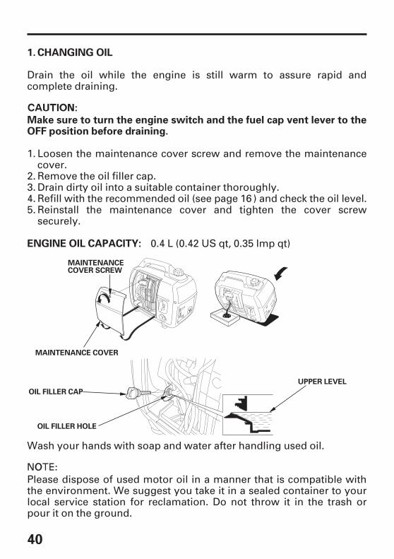
CHANGING OIL
Make sure to turn the engine switch and the fuel cap vent lever to theOFF position before draining.
1.
ENGINE OIL CAPACITY:
OIL FILLER CAP
UPPER LEVEL
OIL FILLER HOLE
MAINTENANCE COVER
MAINTENANCECOVER SCREW
Please dispose of used motor oil in a manner that is compatible withthe environment. We suggest you take it in a sealed container to yourlocal service station for reclamation. Do not throw it in the trash orpour it on the ground.
Wash your hands with soap and water after handling used oil.
Drain the oil while the engine is still warm to assure rapid andcomplete draining.
Loosen the maintenance cover screw and remove the maintenancecover.
0.4 L (0.42 US qt, 0.35 lmp qt)
Reinstall the maintenance cover and tighten the cover screwsecurely.
Refill with the recommended oil (see page ) and check the oil level.Drain dirty oil into a suitable container thoroughly.Remove the oil filler cap.
1.
2.3.4.5.
16

41
AIR CLEANER SERVICE
Do not use gasoline or low flash point solvents for cleaning. They areflammable and explosive under certain conditions.
Never run the generator without the air cleaner. Rapid engine wearmay result.
2.
MAINTENANCE COVER
MAIN AIR CLEANER ELEMENT
MAINTENANCECOVER SCREW
OUTER AIR CLEANERELEMENT
AIR CLEANER ELEMENT
AIR CLEANER COVER
A dirty air cleaner will restrict air flow to the carburetor. To preventcarburetor malfunction, service the air cleaner regularly. Service morefrequently when operating the generator in extremely dusty areas.
Loosen the maintenance cover screw and remove the maintenancecover.
Reinstall the maintenance cover and tighten the cover screwsecurely.
Reinstall the main and outer air cleaner elements and the air cleanercover. Tighten the cover screw securely.
Soak the elements in clean engine oil and squeeze out the excess oil.
Wash the main and outer air cleaner elements in a non-flammableor high flash point solvent and dry them thoroughly.
Loosen the air cleaner cover screw, and remove the air cleaner cover.3.
1.
2.
4.5.
6.

42
SPARK PLUG SERVICE
RECOMMENDED SPARK PLUG:
3.
HANDLE BAR
SPARK PLUG CAP
SPARK PLUG MAINTENANCE COVER
SPARK PLUG WRENCH
CR5HSB (NGK)
To ensure proper engine operation, the spark plug must be properlygapped and free of deposits.
Remove the spark plug maintenance cover.
Remove the spark plug cap.Clean any dirt from around the spark plug base.Use a spark plug wrench to remove the spark plug.
1.
2.3.4.

- -
--
43
The spark plug must be securely tightened. An improperlytightened plug can become very hot and possibly damage thegenerator.Never use a spark plug with an improper heat range.
0.6 0.7 mm(0.024 0.028 in)
SIDE ELECTRODE
Visually inspect the spark plug. Discard it if the insulator is cracked,chipped, or fouled. Clean the spark plug with a wire brush if it is tobe reused.Measure the plug gap with a feeler gauge.Correct as necessary by carefully bending the side electrode.The gap should be:
After a new spark plug has been seated by hand, it should betightened 1/2 turn with a wrench to compress its washer.If a used plug is being reinstalled, it should only require 1/8 to 1/4turn after being seated.
Install the spark plug carefully, by hand, to avoid cross-threading.
Reinstall the spark plug cap on the spark plug securely.Reinstall the spark plug maintenance cover.
0.6 0.7 mm (0.024 0.028 in)
5.
6.
7.8.
9.10.

44
TRANSPORTING/STORAGE9.
Do not drive on a rough road for an extended period with thegenerator on board. If you must transport the generator on a roughroad, drain the fuel from the generator beforehand.
Avoid a place exposed to direct sunlight when putting thegenerator on a vehicle. If the generator is left in an enclosed vehiclefor many hours, high temperature inside the vehicle could causefuel to vaporize resulting in a possible explosion.
Do not operate the generator while it is on a vehicle. Take thegenerator off the vehicle and use it in a well ventilated place.
Do not overfill the tank (there should be no fuel in the filler neck).When transporting the generator:
HOLDING PART
To prevent fuel spillage when transporting or during temporarystorage, the generator should be secured upright in its normaloperating position, with the engine switch OFF.
Allow the engine to cool well before turning the fuel cap vent lever tothe OFF position.
The fuel cap vent lever is turned fully counterclockwise to the OFFposition.
To transport the generator, hold the holding part (shaded areas in thefigure below).

○-
45
Gasoline is extremely flammable and is explosive under certainconditions. Perform this task in a well ventilated area with theengine stopped. Do not smoke or allow flames or sparks in the areaduring this procedure.
SCREW DRIVER
Before storing the unit for an extended period:Be sure the storage area is free of excessive humidity and dust.Drain the fuel.
Drain all gasoline from the fuel tank into an approved gasolinecontainer. We recommend using a commercially availablegasoline hand pump. Do not use an electric pump.
Reinstall the spark plug cap on the spark plug securely.
Turn the engine switch to the OFF position, and tighten the drainscrew securely.
With the drain screw loosened remove the spark plug cap, andpull the starter grip 3 to 4 times to drain the gasoline from the fuelpump.
Turn the engine switch to the ON position, and loosen thecarburetor drain screw and drain the gasoline from the carburetorinto a suitable container.
b.
c.
d.
e.
a.
1.2.

46
STARTER GRIP
Change the engine oil.Remove the spark plug and pour about a tablespoon of clean engineoil into the cylinder. Crank the engine several revolutions todistribute the oil, then reinstall the spark plug.Slowly pull the starter grip until resistance is felt. At this point, thepiston is coming up on its compression stroke and both the intakeand exhaust valves are closed. Storing the engine in this positionwill help to protect it from internal corrosion.
3.4.
5.

47
TROUBLESHOOTING10.
When the engine will not start:
Is there fuel inthe tank?
Refill the fueltank.
Is the enough oilin the engine?
Is the engineswitch ON?
Turn the engineswitch ON.
Add therecommendedoil.
Is the spark plugin goodcondition?
Clean, readjustgap and dry thespark plug.Replace it ifnecessary.
If the engine stilldoes not start,take thegenerator to anauthorizedHonda dealer.
NO
NO
NO
YES
YES
YES
NO
YES

48
Appliance does not operate:
Stop and restartthe engine.
Take theelectricalappliance orequipment toan electricalshop for repair.
Replace theelectricalappliance orequipment.
Take thegenerator to anauthorizedHonda dealer.
Take thegenerator to anauthorizedHonda dealer.
Check theelectricalappliance orequipment forany defects.
Is the Overloadindicator on?
Is the outputindicator on?
Is the AC circuitprotector ON?
Turn the ACcircuit protectorON.
NO
NOYES
YES
NO DEFECTS
DEFECTS
YES
NOExcept U type:

49
No electricity at the DC receptacle:
Is the DC circuitprotector ON?
Turn the DCcircuit protectorON.
Take thegenerator to anauthorizedHonda dealer.
NO
YES
× ××
-
50
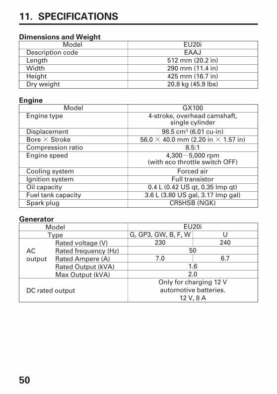
SPECIFICATIONS11.
Dimensions and Weight
Engine
Generator
512 mm (20.2 in)EAAJ
290 mm (11.4 in)425 mm (16.7 in)20.8 kg (45.9 lbs)
GX100
EU20iModelDescription codeLengthWidthHeightDry weight
CR5HSB (NGK)
Full transistorForced air
8.5:156.0 40.0 mm (2.20 in 1.57 in)
98.5 cm (6.01 cu-in)
4-stroke, overhead camshaft,single cylinder
ModelEngine type
DisplacementBore StrokeCompression ratioEngine speed
Cooling systemIgnition systemOil capacityFuel tank capacitySpark plug
4,300 5,000 rpm(with eco throttle switch OFF)
ModelType
ACoutput
DC rated output
EU20iG, GP3, GW, B, F, W
230U
24050
7.0 6.7
Only for charging 12 Vautomotive batteries.
12 V, 8 A
1.62.0
0.4 L (0.42 US qt, 0.35 lmp qt)3.6 L (3.80 US gal, 3.17 lmp gal)
Rated voltage (V)Rated frequency (Hz)Rated Ampere (A)Rated Output (kVA)Max Output (kVA)

51
Noise
CONTROLPANEL
Center
1.60 m
1.0 m
Microphone point
EU20iG, GP3, GW, B, F, W
Not exceed70 dB (A)
U
89 dB (A)
88 dB (A)
1 dB (A)
ModelType
Sound pressure level atthe workstation(2006/42/EC)
UncertaintyMeasured sound power level(2000/14/EC, 2005/88/EC)UncertaintyGuaranteed soundpower level(2000/14/EC, 2005/88/EC)
‘‘the figures quoted are emission levels and are not necessarily safeworking levels. Whilst there is a correlation between the emission andexposure levels, this cannot be used reliably to determine whether ornot further precautions are required. Factors that influence the actuallevel of exposure of work-force include the characteristics of the workroom, the other sources of noise, etc. i.e. the number of machines andother adjacent processes, and the length of time for which an operatoris exposed to the noise. Also the permissible exposure level can varyfrom country. This information, however, will enable the user of themachine to make a better evaluation of the hazard and risk’’.
Specifications are subject to change without notice.

--
52
WIRING DIAGRAM12.
INDEX
ABBREVIATIONS
Symbol Part name Symbol Part name
WIRE COLOR CODE
SWITCH CONNECTIONS
ECO THROTTLE SWITCH
AC, CPAC, NFACOR(B)CotCPBDC, CPDC, DDC, NFDCORDC, WEcoSwEgBEgGESwExWFrBFrG(G)GeBGTIgCIUMWOALOIOLSwPCPLRBx
SPSpU
AC Circuit ProtectorAC Noise FilterAC Output ReceptacleB TypeParallel operation socketControl Panel BlockDC Circuit ProtectorDC DiodeDC Noise FilterDC Output ReceptacleDC WindingEco throttle switchEngine BlockEngine GroundEngine SwitchExciter WindingFrame BlockFrame GroundG, GW, GP3 TypesGenerator BlockGround TerminalIgnition CoilInverter UnitMain WindingOil Alert IndicatorOverload IndicatorOil Level SwitchPulser CoilOutput IndicatorReceptacle Box forParallel OperationSpark PlugSpark Unit
StpM
SWTo Ge(W)
Stepping Motor(Throttle Control)Sub WindingTo GeneratorW Type
BlYBuGRWBrLgGrLbOP
BLACKYELLOWBLUEGREENREDWHITEBROWNLIGHT GREENGRAYLIGHT BLUEORANGEPINK
.................................................................................B, W, F, G Types . W 1.................................................................................................U Type . W 2
COM (-) SW
ON
OFF
(See inside back cover)
53
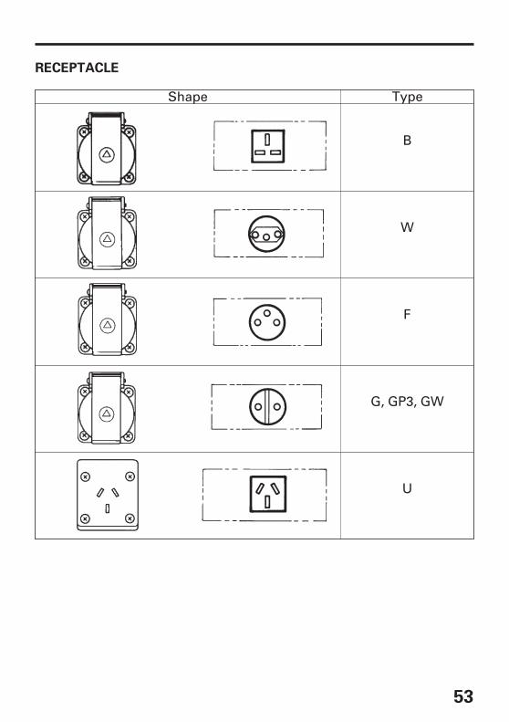
RECEPTACLE
Shape Type
B
W
F
U
G, GP3, GW

DIAGRAMA DE CONEXIONES
SCHÉMA DE CABLAGE
SCHALTPLAN
WIRING DIAGRAM

-W 1

-W 2


Pour plus d’informations, s’adresser au Centre d’informations clients Honda àl’adresse ou numéro de téléphone suivants:
Para obtener más información, póngase en contacto con el Centro deinformación para clientes Honda en la dirección o número de teléfono siguientes:
ADRESSES DES PRINCIPAUX CONCESSIONNAIRES Honda
DIRECCIONES DE LOS PRINCIPLES CONCESIONARIOS Honda
MAJOR Honda DISTRIBUTOR ADDRESSES
ADRESSEN DER WICHTIGSTEN Honda-HAUPTHÄNDLER
For further information, please contact Honda Customer InformationCentre at the following address or telephone number:
We itere Informat ionen erhalten Sie gerne vom Honda-Kundeninformationszentrum unter der folgenden Adresse oderTelefonnummer:

+
+
+
+
@
+
+
@
+
+
@
-
+
+
@
+
+
+
+
+
+
+
+
@
+
+
@
+
+
@
AUSTRIA
BALTIC STATES
(Estonia/Latvia/
Lithuania)
BELGIUM
BULGARIA
CROATIA
CYPRUS
CZECH REPUBLIC
DENMARK
FINLAND
FRANCE
GERMANY
GREECE
Honda Motor Europe (North)
Honda Motor Europe Ltd.
Honda Motor Europe (North)
Kirov Ltd.
Hongoldonia d.o.o.
Alexander Dimitriou & Sons Ltd.
BG Technik cs, a.s.
Tima Products A/S
OY Brandt AB.
Honda Relations Clients
Honda Motor Europe (North)
GmbH
General Automotive Co S.A.
Hondastraße 1
2351 Wiener Neudorf
Tel. : 43 (0)2236 690 0
Fax : 43 (0)2236 690 480
http://www.honda.at
Estonian Branch
Tulika 15/17
10613 Tallinn
Tel. : 372 6801 300
Fax : 372 6801 301
honda.baltic honda-eu.
com.
Doornveld 180-184
1731 Zellik
Tel. : 32 2620 10 00
Fax : 32 2620 10 01
http://www.honda.be
BH_PE HONDA-EU.COM
49 Tsaritsa Yoana blvd
1324 Sofia
Tel. : 359 2 93 30 892
Fax : 359 2 93 30 814
http://www.kirov.net
honda kirov.net
Jelkovecka Cesta 5
10360 Sesvete Zagreb
Tel. : 385 1 2002053
Fax : 385 1 2020754
http://www.hongoldonia.hr
jure hongoldonia.hr
162, Yiannos Kranidiotis Avenue
2235 Latsia, Nicosia
Tel. : 357 22 715 300
Fax : 357 22 715 400
U Zavodiste 251/8
15900 Prague 5 - Velka
Chuchle
Tel. : 420 2 838 70 850
Fax : 420 2 667 111 45
http://www.honda-stroje.cz
Tårnfalkevej 16
2650 Hvidovre
Tel. : 45 36 34 25 50
Fax : 45 36 77 16 30
http://www.tima.dk
Tuupakantie 7B
01740 Vantaa
Tel. : 358 20 775 7200
Fax : 358 9 878 5276
http://www.brandt.fi
TSA 80627
45146 St Jean de la Ruelle Cedex
Tel. : 02 38 81 33 90
Fax : 02 38 81 33 91
http://www.honda-fr.com
espaceclient honda-eu.com
Sprendlinger Landstraße 166
63069 Offenbach am Main
Tel. : 49 69 8309-0
Fax : 49 69 8320 20
http://www.honda.de
info post.honda.de
71 Leoforos Athinon
10173 Athens
Tel. : 30 210 349 7809
Fax : 30 210 346 7329
http://www.honda.gr
info saracakis.gr

+
+
@
+
+
+
+
@
+
+
+
+ +
+
+
+
@
+
+
@
+
+
@
+
+
@
+
+
@
+
+
@
HUNGARY MALTA PORTUGAL
NETHERLANDSICELAND REPUBLIC OF
BELARUS
NORWAYIRELAND ROMANIA
POLANDITALY RUSSIA
Motor Pedo Co., Ltd. The Associated Motors
Company Ltd.
Honda Portugal, S.A.
Honda Motor Europe (North)Bernhard ehf.
Scanlink Ltd.
Berema ASTwo Wheels ltd Hit Power Motor Srl
Aries Power Equipment Sp. z o.o.Honda Italia Industriale S.p.A. Honda Motor RUS LLC
Kamaraerdei ut 3.
2040 Budaors
Tel. : 36 23 444 971
Fax : 36 23 444 972
http://www.hondakisgepek.hu
info hondakisgepek.hu
New Street in San Gwakkin Road
Mriehel Bypass, Mriehel QRM17
Tel. : 356 21 498 561
Fax : 356 21 480 150
Rua Fontes Pereira de Melo 16
Abrunheira, 2714-506 Sintra
Tel. : 351 21 915 53 33
Fax : 351 21 915 23 54
http://www.honda.pt
honda.produtos honda-eu.
com
Afd. Power Equipment-
Capronilaan 1
1119 NN Schiphol-Rijk
Tel. : 31 20 7070000
Fax : 31 20 7070001
http://www.honda.nl
Vatnagardar 24-26
104 Reykdjavik
Tel. : 354 520 1100
Fax : 354 520 1101
http://www.honda.is
Kozlova Drive, 9
220037 Minsk
Tel. : 375 172 999090
Fax : 375 172 999900
http://www.hondapower.by
P.O. Box 454
1401 Ski
Tel. : 47 64 86 05 00
Fax : 47 64 86 05 49
http://www.berema.no
berema berema.no
M50 Business Park, Ballymount
Dublin 12
Tel. : 353 1 4381900
Fax : 353 1 4607851
http://www.hondaireland.ie
Service hondaireland.ie
Calea Giulesti N° 6-8 Sector 6
060274 Bucuresti
Tel. : 40 21 637 04 58
Fax : 40 21 637 04 78
http://www.honda.ro
hit_power honda.ro
ul. Wroclawska 25
01-493 Warszawa
Tel. : 48 (22) 861 43 01
Fax : 48 (22) 861 43 02
http://www.ariespower.pl
http://www.mojahonda.pl
info ariespower.pl
Via della Cecchignola, 5/7
00143 Roma
Tel. : 848 846 632
Fax : 39 065 4928 400
http://www.hondaitalia.com
info.power honda-eu.com
21. MKAD 47 km., Leninsky district.
Moscow region, 142784 Russia
Tel. : 7 (495) 745 20 80
Fax : 7 (495) 745 20 81
http://www.honda.co.ru
postoffice honda.co.ru

+
+
+
+
@
@
+
+
@
+
+
+
+
+
+
+
+
@
+
+
+
+
+
@
SERBIA &
MONTENEGRO
Tenerife province
SWEDEN
SWITZERLAND
SPAIN &
Las Palmas province
SLOVAKIA REPUBLIC
UKRAINE
UNITED KINGDOM
SLOVENIA AUSTRALIA
TURKEY
Bazis Grupa d.o.o.
(Canary Islands)
Automocion Canarias S.A.
Honda Nordic AB
Honda Suisse S.A.
(Canary Islands)
Greens Power Products, S.L.
Honda Slovakia, spol. s r.o.
Honda Ukraine LLC
Honda (UK) Power Equipment
AS Domzale Moto Center D.O.O. Honda Australia Motorcycle and
Power Equipment Pty. Ltd
Anadolu Motor Uretim ve
Pazarlama AS
Grcica Milenka 39
11000 Belgrade
Tel. : 381 11 3820 295
Fax : 381 11 3820 296
http://www.hondasrbija.co.rs
Carretera General del Sur, KM. 8,8
38107 Santa Cruz de Tenerife
Tel. : 34 (922) 620 617
Fax : 34 (922) 618 042
http://www.aucasa.com
ventas aucasa.com
taller aucasa.com
Box 50583 - Västkustvägen 17
20215 Malmö
Tel. : 46 (0)40 600 23 00
Fax : 46 (0)40 600 23 19
http://www.honda.se
hpesinfo honda-eu.com
10, Route des Moulières
1214 Vemier - Genève
Tel. : 41 (0)22 939 09 09
Fax : 41 (0)22 939 09 97
http://www.honda.ch
Poligono Industrial Congost -
Av Ramon Ciurans n°2
08530 La Garriga - Barcelona
Tel. : 34 93 860 50 25
Fax : 34 93 871 81 80
http://www.hondaencasa.com
Prievozská 6 821 09 Bratislava
Tel. : 421 2 32131112
Fax : 421 2 32131111
http://www.honda.sk
101 Volodymyrska Str. - Build. 2
Kyiv 01033
Tel. : 380 44 390 1414
Fax : 380 44 390 1410
http://www.honda.ua
CR honda.ua
470 London Road
Slough - Berkshire, SL3 8QY
Tel. : 44 (0)845 200 8000
http://www.honda.co.uk
Blatnica 3A
1236 Trzin
Tel. : 386 1 562 22 42
Fax : 386 1 562 37 05
http://www.as-domzale-motoc.si
1954-1956 Hume Highway
Campbellfield Victoria 3061
Tel. : (03) 9270 1111
Fax : (03) 9270 1133
Esentepe mah. Anadolu
Cad. No: 5
Kartal 34870 Istanbul
Tel. : 90 216 389 59 60
Fax : 90 216 353 31 98
http://www.anadolumotor.com.tr
antor antor.com.tr

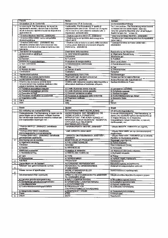
"EC Declaration of Conformity" CONTENT OUTLINE"CE-Déclaration de conformité" DESCRIPTION DE TABLE DES MATIERES "EU-Konformitätserklärung" INHALTSÜBERSICHT DESCRIPCIÓN GENERAL DEL CONTENIDO DE LA "Declaración de Conformidad CE"
*1: see specification page.*1: voir page de spécifications
*1: Siehe Spezifikationen-Seite*1: consulte la página de las
especificaciones


oHonda Motor Co., Ltd. 2009efgsY16000.2009.08
Printed in Japan36Z0761000X36-Z07-6100
KS