generic 150 beam slider user guide template
TRANSCRIPT

TECHNICAL DATA SHEET
safewaze.com | (P) 704-262-7893 | (F) 704-262-9051 322 Industrial Court, Concord, NC 28025
The Safewaze™ premier sliding beam anchor is designed to be used as a single-person anchor point on horizontal beams. It features a double-rivet fixed clamp on one end and a keyed sliding clamp on the other. The centered D-ring prevents jamming on a beam flange, and allows for smoother sliding.
19 in (482.6 mm)
3.5 in (88.9 mm) to 14 in (355.6 mm)
Forged anodized aluminum cross barStainless steel clamps, latches and springsCarbon steel D-ring
3.75 lbs (1.7 kg)
5,000 lbs (2267.96 kg)
Meets OSHA 1926.502 - ANSI Z359.1 - ANSI A10.32
Description
Overall Length
Fits Beam Flange Width
Materials
Weight
Minimum Breaking Load
Applicable Standards
FS860Premier Beam Anchor
*Anchorages used for attachment of personal fall arrest equipment shall be independent of any anchorage being used to support or supend platforms and be capable of supporting at least 5,000 (22.2kN) pounds per employee attached.
3070
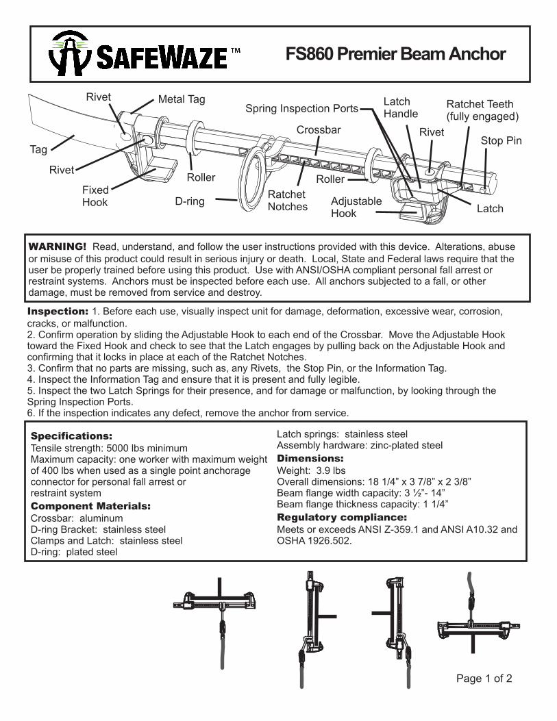
Latch Handle
Stop PinRivet
Rivet
Rivet
Crossbar
Fixed Hook Adjustable
HookD-ring
Latch
Spring Inspection Ports Ratchet Teeth (fully engaged)
Tag
Ratchet Notches
RollerRoller
Metal Tag
Page 1 of 2
WARNING! Read, understand, and follow the user instructions provided with this device. Alterations, abuse or misuse of this product could result in serious injury or death. Local, State and Federal laws require that the user be properly trained before using this product. Use with ANSI/OSHA compliant personal fall arrest or restraint systems. Anchors must be inspected before each use. All anchors subjected to a fall, or other damage, must be removed from service and destroy.
Inspection: 1. Before each use, visually inspect unit for damage, deformation, excessive wear, corrosion, cracks, or malfunction. 2. Confirm operation by sliding the Adjustable Hook to each end of the Crossbar. Move the Adjustable Hooktoward the Fixed Hook and check to see that the Latch engages by pulling back on the Adjustable Hook andconfirming that it locks in place at each of the Ratchet Notches.3. Confirm that no parts are missing, such as, any Rivets, the Stop Pin, or the Information Tag.4. Inspect the Information Tag and ensure that it is present and fully legible.5. Inspect the two Latch Springs for their presence, and for damage or malfunction, by looking through theSpring Inspection Ports.6. If the inspection indicates any defect, remove the anchor from service.
Specifications: Latch springs: stainless steelAssembly hardware: zinc-plated steelTensile strength: 5000 lbs minimumDimensions:Maximum capacity: one worker with maximum weight
of 400 lbs when used as a single point anchorage Weight: 3.9 lbsconnector for personal fall arrest or Overall dimensions: 18 1/4” x 3 7/8” x 2 3/8”restraint system Beam flange width capacity: 3 ½”- 14”
Beam flange thickness capacity: 1 1/4”Component Materials:Regulatory compliance: Crossbar: aluminum
D-ring Bracket: stainless steel Meets or exceeds ANSI Z-359.1 and ANSI A10.32 and Clamps and Latch: stainless steel OSHA 1926.502.D-ring: plated steel
FS860 Premier Beam Anchor
Page 2 of 2
INSTALLATION:1. Locate a structural steel beam flange capable of withstanding a 5,000 lb. static load or meeting OSHA1926.502 requirements for a safety factor of two. The anchor may be attached to a flange located on the top,bottom, or side of the beam.2. Push in on the Latch handle to allow the Adjustable Hook to move.3. Fit the Hooks over the edges of the beam flange, keeping the unit perpendicular to the beam.4. Slide the Adjustable Hook so that both Hooks are snug against the beam flange.5. Pull back on the Adjustable Hook to ensure that the Ratchet Teeth are fully seated in the nearest RatchetNotches.6. Tug, rock, and twist the anchor to ensure that it cannot come off of the flange.
ALWAYS readjust according to steps 1 through 6, above, when moving to a new or different size beam.
MAINTENANCE, CLEANING & STORAGE: Servicing must be performed by the manufacturer only. Only OEM parts may be used to repair the product. Cleaning periodically will prolong the life and proper functioning of the product. Clean with compressed air and/or a stiff brush using plain water or a mild soap and water solution. Do not use any corrosive chemicals that could damage the unit. Wipe all surfaces with a clean dry cloth, then hang to dry or use compressed air. The storage area should be clean, dry, and free of corrosive or other degrading elements.
TRAINING: It is the responsibility of the user and purchaser of this equipment to be familiar with the instructions, operation, limitations and consequences of improper use of this equipment. Users and purchasers of this equipment must be trained in the correct use and care of this equipment. It is recommended that this be part of an ongoing training schedule.
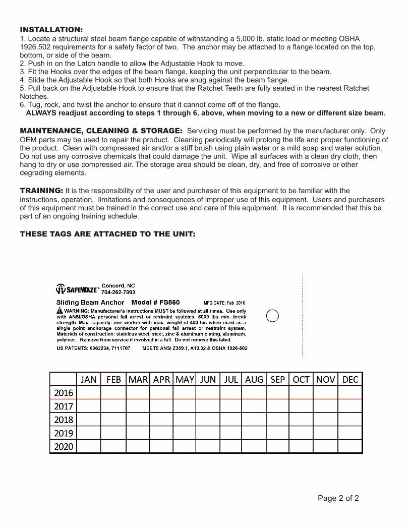
THESE TAGS ARE ATTACHED TO THE UNIT: