generic design assessment - edf and areva uk epr - step 3 ... · step 3 reactor chemistry...
TRANSCRIPT

Health and Safety Executive
NUCLEAR DIRECTORATE
GENERIC DESIGN ASSESSMENT – NEW CIVIL REACTOR BUILD
STEP 3 REACTOR CHEMISTRY ASSESSMENT OF THE EDF AND AREVA UK EPR
DIVISION 6 ASSESSMENT REPORT NO. AR 09/036
HSE Nuclear Directorate Redgrave Court Merton Road Bootle Merseyside L20 7HS

HSE Nuclear Directorate Division 6 Assessment Report No. AR 09/036
EXECUTIVE SUMMARY
This report presents the findings of the reactor chemistry assessment of the EDF and AREVA UK EPR Pre-Construction Safety Report (PCSR) (Ref. 1) undertaken as part of Step 3 of the Generic Design Assessment (GDA) process.
Scope of Assessment Carried Out
The scope of the reactor chemistry assessment is detailed within the Project Initiation Document (PID) and its addendum (Refs 10 and 11).
There was no Step 2 assessment for chemistry and the UK EPR safety case contains no sections dedicated to chemistry. This report for Step 3 therefore identifies the main chemistry claims made in various chapters of the PCSR together with claims made in response to Technical Queries (TQs) and at meetings. The information gathered by this process was sufficient to allow consideration of arguments presented by EDF and AREVA.
It is important to stress that the Step 3 report represents a progress statement; some areas are not programmed for assessment until Step 4. Not all areas have been assessed to the same extent due to the limited detail of some analyses presented to date.
During Step 3 we raised 14 TQs and commissioned contract support to examine the factors influencing operator radiation exposure in normal operation.
Conclusions
We were encouraged that EDF and AREVA have put considerable effort into the chemistry of the UK EPR design but the principal aspects of the presentation of safety that need improvement are;
1. EDF and AREVA have provided little information on the chemistry of boron in the primary circuit and chemical effects in the secondary circuit and its ancillaries, although we understand some analyses may have been undertaken. This approach is not consistent with current expectations and further detail will need to be provided.
2. Severe accidents are described extensively, however the specific application of chemistry to the UK EPR is lacking in detail.
3. The presentation that has been made was largely based upon experience from older plants and not quantitative analyses. A more balanced approach would avoid difficulties associated with dataset selection, sample population and numerical limits.
4. A topic report or PCSR overview of chemistry (including boron chemistry and faults) will be needed during Step 4.
Additional support contracts are being put in place to provide support in reviewing EDF and AREVA documentation for different chemistry aspects of accidents, materials and operations. Assessment of the chemistry of accidents will be co-ordinated with equivalent fault studies planned to begin in Step 4. The programme for Step 4 allows limited time for assessment of severe accidents.
So far no chemistry-related Regulatory Issues (RIs) have been identified and EDF and AREVA’s readiness to address TQs is encouraging. The possibility of changes to the detailed design for boronation, hydrogen or secondary circuits arising from assessments during Step 4 cannot be ruled out.
Page (i)

HSE Nuclear Directorate Division 6 Assessment Report No. AR 09/036
LIST OF ABBREVIATIONS
ALARP As Low as Reasonably Practicable
AOA Axial Offset Anomoly (see also CIPS)
ASN Autorité de sûreté nucléaire (Nuclear Safety Authority, France)
ATD Chemical Treatment Plant
AVS Annulus Ventilation System
BMS (Nuclear Directorate) Business Management System
BOP Balance Of Plant
CCWS Component Cooling Water System
CHRS Containment Heat Removal System
CIPS Crud-Induced Power Shift
CoSHH Control of Substances Hazardous to Health (Regulations)
CP Corrosion Product
CPP Condensate Polishing Plant
CRDM Control Rod Drive Mechanism
CREDO Chemical and Radiochemical EPR Design Optimisation
CSTS Condensate Storage and Transfer System
CVCS Chemical and Volume Control System
DLS Chilled Water System
DSEAR Dangerous Substances and Explosive Atmosphere Regulations
EA The Environment Agency
EBA Enriched Boric Acid
EBS Extra Borating System
EDF Électricité de France
EMIT Examination, Maintenance, Inspection and Testing
EPR European Pressurized Water Reactor
EPRI Electric Power Research Institute (US)
ESWS Essential Service Water System
EYT Hydrogen Control System
FA3 Flamanville 3
FAC Flow Accelerated Corrosion
FP Fission Product
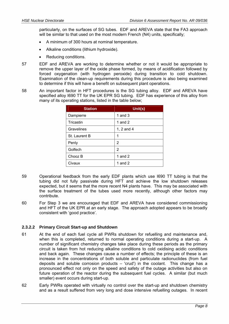
FPCS Fuel Pond Cooling System
FPPS Fuel Pond Purification System
GDA Generic Design Assessment
GWPS Gaseous Waste Processing System
HEPA High Efficiency Particulate Air
HFT Hot Functional Testing
Page (ii)
HSE Nuclear Directorate Division 6 Assessment Report No. AR 09/036
LIST OF ABBREVIATIONS
HSE The Health and Safety Executive
HX Heat Exchanger
I600 Inconel 600 alloy
I690 Inconel 690 alloy
IAEA The International Atomic Energy Agency
IGA Inter-granular Attack
IGSCC Inter-granular Stress Corrosion Cracking
IRWST In-containment Reactor Water Storage Tank
IX Ion Exchange
LHSI Low Head Safety Injection
LOCA Loss of Coolant Accident
LTCP Low-temperature Crack Propogation
MA Mill Annealed alloy (specifically Inconel 600 or 690)
MHSI Medium Head Safety Injection
MTC Moderator Temperature Coefficient
ND The (HSE) Nuclear Directorate
NRC Nuclear Regulatory Commission (US)
NSS Nuclear Sampling System
NSSS Nuclear Steam Supply System
OL3 Olkiluoto 3
ORE Operator Radiation Exposure
PAR Passive Autocatalytic Recombiner
PASS Post-Accident Sampling System
PCER Pre-construction Environment Report
PCSR Pre-construction Safety Report
PID Project Initiation Document
PRA Probabilistic Risk Assessment
PSR Preliminary Safety Review
PWR Pressurised Water Reactor
PWSCC Primary Water Stress Corrosion Cracking
PZR Pressuriser
RBWMS Reactor Borated Water Make-up System
RCDT Reactor Coolant Drain Tank
RCP Reactor Coolant Pump
RCS Reactor Cooling System
RES Steam Generator secondary side sampling system (part of NSS)
RHRS Residual Heat Removal System
Page (iii)

HSE Nuclear Directorate Division 6 Assessment Report No. AR 09/036
LIST OF ABBREVIATIONS
RI Regulatory Issue
RIA Regulatory Issue Action
RO Regulatory Observation
RP Requesting Party
RPV Reactor Pressure Vessel
RSG Recirculatory Steam Generator
RWST Refuelling Water Storage Tank
SAP Safety Assessment Principle
SCC Stress Corrosion Cracking
SFAIRP So Far as is Reasonably Practicable
SFP Spent Fuel Pool
SG Steam Generator
SGBS Steam Generator Blowdown System
SGTR Steam Generator Tube Rupture
SINCAD SIlver-INdium-CADmium alloy
SIS Safety Injection System
SIT Feedwater Chemical Sampling System
SSC System, Structure or Component
STUK Säteilyturvakeskus (Radiation and Nuclear Safety Authority, Finland)
TAG (Nuclear Directorate) Technical Assessment Guide
TQ Technical Query
TS Tube Sheet (in SG)
TSC Technical Support Contractor
TSP Tube Support Plate (in SG)
TSP Trisodium Phosphate
TT Thermally Treated alloy (specifically Inconel 600 or 690)
VCT Volume Control Tank
VGB Verenigate Grosskraftwerke Betreiber (Federation of Large Power Station Operators, Germany)
WENRA The Western European Nuclear Regulators’ Association
Page (iv)
HSE Nuclear Directorate Division 6 Assessment Report No. AR 09/036
Page (v)
TABLE OF CONTENTS
1 INTRODUCTION...................................................................................................................... 1
1.1 GDA Process..................................................................................................................... 1
1.2 Assessment Methodology ................................................................................................. 1
1.3 Assessment Objectives ..................................................................................................... 2
1.4 Assessment Scope............................................................................................................ 2
2 NUCLEAR DIRECTORATE’S ASSESSMENT ........................................................................ 4
2.1 Requesting Party’s Safety Case........................................................................................ 4
2.1.1 Structure................................................................................................................. 4
2.1.2 Reactor Chemistry Content .................................................................................... 4
2.1.3 Reactor Chemistry Claims...................................................................................... 4
2.2 Standards and Criteria ...................................................................................................... 5
2.2.1 Safety Assessment Principles ................................................................................ 5
2.2.2 Other Nuclear Directorate Guidance ...................................................................... 5
2.2.3 External Standards and Guidance.......................................................................... 5
2.3 Assessment....................................................................................................................... 6
2.3.1 Chemistry Standards.............................................................................................. 6
2.3.2 Start-up and Shutdown Chemistry.......................................................................... 7
2.3.3 Primary Circuit ...................................................................................................... 10
2.3.4 Secondary Circuit ................................................................................................. 26
2.3.5 Fuel Pool Systems ............................................................................................... 34
2.3.6 Waste Treatment Systems ................................................................................... 37
2.3.7 Ancillary Systems ................................................................................................. 38
2.3.8 Accident Chemistry............................................................................................... 40
2.3.9 GDA Assessment Requirements.......................................................................... 45
3 CONCLUSIONS AND RECOMMENDATIONS...................................................................... 48
4 REFERENCES....................................................................................................................... 50
Figure 1: Reactor Chemistry Safety Assessment Principles ‘Mind Map’
Table 1: UK EPR Pre-Construction Safety Report Reactor Chemistry Content
Table 2: Relevant Safety Assessment Principles Considered During Step 3
Table 3: Relevant Technical Assessment Guides Considered During Step 3
Annex 1: Reactor Chemistry – Status of Regulatory Issues and Observations

HSE Nuclear Directorate Division 6 Assessment Report No. AR 09/036
1 INTRODUCTION
1 This reports presents the findings of the reactor chemistry assessment of the EDF and AREVA UK EPR Pre-Construction Safety Report (PCSR) (Ref. 1) undertaken as part of Step 3 of the HSE Generic Design Assessment (GDA) process. This assessment has been undertaken in line with the requirements of the Business Management System (BMS) document AST/001 (Ref. 2) and its associated guidance document G/AST/001 (Ref. 3). AST/001 sets down the process of assessment within the Nuclear Directorate (ND) and explains the process associated with sampling of safety case documentation. The Safety Assessment Principles (SAPs) (Ref. 4) have been used as the basis for the assessment of reactor chemistry associated with the EPR design. The SAPs require that chemical processes taking place and chemical hazards which exist on a nuclear power plant be identified and considered in safety assessments. Ultimately, the goal of assessment is to reach an independent and informed judgment on the adequacy of safety in the generic design.
1.1 GDA Process
2 The Health and Safety Executive (HSE) and the Environment Agency (EA) developed the GDA process in response to a request from the Government following its 2006 Energy Review (Ref. 5). In summary, HSE and EA proposed that new nuclear power stations should be subject to a methodical, defined, multi stage pre-licensing process, including an assessment phase for generic designs.
3 Subsequently, the nuclear regulators published a suite of guidance material on GDA for new nuclear power station designs (Ref. 7, in January 2007 and August 2008) which led to a number of companies asking to participate in GDA.
4 The GDA process splits the Nuclear Directorate (ND) assessment into 4 Steps and 15 assessment areas, one area being reactor chemistry. Overall, Steps 1 and 2 have been completed (but not for reactor chemistry expressly) and reported previously (Ref. 6) and ND has completed Step 3 of GDA, which has led to the production of this reactor chemistry assessment report. GDA Step 3 is defined as an ‘overall design safety review’. The overall ND description and aims for Step 3 (and the other Steps) are given in the GDA guidance material (Ref. 7).
5 GDA Step 3 is not a complete assessment. Implicit in the definition of GDA is that it is expected that assessment of the design will continue in GDA Step 4. This is defined as a ‘detailed design assessment’ and will provide an in-depth assessment of the safety case and generic site envelope (Ref. 7). To put these aims into context of a UK safety case, Step 3 represents assessment of the ‘arguments’ and Step 4 represents the ‘evidence’ stage of a structured ‘claims - arguments - evidence’ safety case.
1.2 Assessment Methodology
6 As stated previously (para. 1) this report has been prepared in accordance with relevant ND guidance (Refs 8 and 9), which also informs the methodology used, namely a sampling basis, dictated by consideration of risk and hazard significance, in coordination with the other assessment disciplines and the scope defined in the Project Initiation Document (PID) (Refs 10 & 11).
7 The Step 3 assessment process consists of examining the arguments and identifying the evidence in RP safety reports relevant to reactor chemistry. These are then assessed against the expectations and requirements of the SAPs and other guidance considered appropriate. Further details on the information that supported this assessment are given in Section 2.2 of this report.
Page 1

HSE Nuclear Directorate Division 6 Assessment Report No. AR 09/036
8 The basis of the assessment undertaken to prepare this report is therefore:
Reading the appropriate chapters of the RP’s PCSR safety report.
Consideration of internal and international standards and guidance.
Consideration of international experience, operational feedback and expertise.
Consideration of assessments performed by other regulators, especially their findings.
Interaction with other relevant technical areas (where possible).
Following the GDA interface arrangements (Ref. 6); raising and issuing of Technical Queries (TQs) followed by assessment of RP responses.
Holding the necessary technical meetings to progress the identified lines of enquiry.
9 Consistent with the GDA deadlines and to provide ND with information for use in our assessment of reactor chemistry in the UK EPR, we have initiated a significant programme of work involving a number of Technical Support Contractors (TSC). This external work programme is just beginning and has already provided seminars for several ND staff. Some initial feedback from the programme has been included in this report. The programme of TSC support will increase during Step 4.
1.3 Assessment Objectives
10 In line with the generic aims for Step 3 (Ref. 6), the following general objectives have informed the assessment for reactor chemistry:
Improve ND knowledge of the design.
Identify significant issues.
Identify whether any significant design or safety case changes may be needed.
Identify major issues that may affect design acceptance and attempt to resolve them.
Achieve a significant reduction in regulatory uncertainty.
11 Timely and appropriate input to each of these activities was also considered as an objective during the assessment process. The assessment resulted in this assessment report (effectively a progress statement) prepared against the defined assessment scope for reactor chemistry in Step 3 which concludes on the adequacy or otherwise of the reactor chemistry of the generic design.
12 This assessment report is a principal output from Step 3. This report will be used by ND to produce a cross-discipline project assessment report of the reactor design at the end of Step 3, taking into account the findings from the other assessment areas.
1.4 Assessment Scope
13 As indicated previously, para. 6, prior to instigation of the Step 3 assessment a PID (Ref. 10) was prepared which defined the scope of the assessment of reactor chemistry. Part way through Step 3 an addendum to this PID (Ref. 11) was prepared which accounted for the increased ND resource. Together these documents formed the basis for the subsequent assessment.
14 In order to understand the scope of the assessment conducted, it is first sensible to consider the definition of reactor chemistry that has been applied during this assessment such that the boundaries are clearly stated. For the purpose of this assessment reactor chemistry was taken to be:
Page 2

HSE Nuclear Directorate Division 6 Assessment Report No. AR 09/036
“the chemistry of the design including the effects of coolant chemistry on reactivity, pressure boundary integrity, fuel and core component integrity, fuel storage in cooling pools, radioactive waste generation and radiological doses to workers.”
15 Thus, reactor chemistry is principally concerned with five main areas: coolant reactivity control, protection of the structural materials (specifically related to integrity of the pressure boundaries), maintaining fuel integrity and performance, minimisation of out of core radiation fields and releases during accident conditions. The relative influence each of these can have on safety can vary depending upon the system under assessment; however these main areas were considered throughout.
16 Historically, reactor chemistry was poorly controlled in early Pressurised Water Reactors (PWRs) which gave rise to a number of safety issues related to structural integrity, fuel damage and high radiation fields as might be expected. Subsequently, recognition of the importance of a properly controlled chemistry led to great improvements in each of these areas and modern PWRs would be expected to operate under a regime where due consideration has been given to each of these aspects.
17 In line with the PID, the assessments of reactor chemistry during Step 3 has concentrated on chemical processes that:
May cause an uncontrolled variation in core reactivity.
May threaten the containment of nuclear matter.
Contribute to operator radiation exposure.
Generate radioactive waste and discharges.
Determine source terms for severe accident analysis.
18 Due to the nature of the GDA process, it was not considered feasible or realistic for the RP’s to be able to fully define the chemistry that may be used at this stage. As such detailed site-specific aspects and commissioning are excluded from the assessment during this Step and are to be considered during Phase 2 (licensing). However, it is considered appropriate to regard these aspects in more general terms during Step 3 (and Step 4) especially where it is deemed appropriate that the RP must demonstrate the capability of the design to accommodate the likely range of operating chemistry regimes or conditions, and cope with deviations from normal chemistry without ‘cliff edge’ effects.
19 Reactor chemistry is an area which interacts with a number of other GDA technical assessment disciplines. Principal amongst these are the radiation protection, structural integrity, radwaste and fault studies areas where chemistry can have a direct impact on the resultant consequences and hence safety. For the same reasons reactor chemistry is of interest to the EA as part of their assessment processes; however, this does not preclude interaction with the other areas. For all the disciplines there is significant and appropriate coordination between technical areas to ensure that the regulatory effort is proportionate and targeted.
20 It should be noted that reactor chemistry was not an assessment area during Step 2 and assessment did not start at the outset of Step 3. This means that the assessment for reactor chemistry is not as progressed as some of the other technical disciplines considered but this can be recovered in Step 4. Specifically for Step 3, this meant that the Step 2 assessment had to be effectively incorporated into the Step 3 scope. It is also worth noting that none of the other disciplines assessed during Step 2 raised any issues related to reactor chemistry during their Step 2 assessment work.
Page 3

HSE Nuclear Directorate Division 6 Assessment Report No. AR 09/036
2 NUCLEAR DIRECTORATE’S ASSESSMENT
2.1 Requesting Party’s Safety Case
2.1.1 Structure
21 The EDF and AREVA safety case for UK EPR is contained within a PCSR which contains claims and some arguments, with references out to supporting documents. The UK PCSR was developed from a Preliminary Safety Review (PSR) originally produced for the French nuclear safety authority, ASN (Autorité de sûreté nucléaire), and does not contain a dedicated section on chemistry. Significant arguments and evidence lie in documents outside the PCSR and the most useful information for reactor chemistry has been obtained from translations requested by ND and from discussions with staff in EDF and AREVA, who have been very helpful.
22 It is clear to us from our discussions with RP staff and from looking at the designs that EDF and AREVA have taken account of chemistry issues with earlier types of PWR, such that the impact of chemistry on common safety issues should be much reduced in UK EPR. However it must be said that the formal presentation of safety arguments involving chemistry, and providing an auditable trail identifying responsibilities, is still being developed by EDF and AREVA.
2.1.2 Reactor Chemistry Content
23 Since the PCSR does not contain a dedicated section on reactor chemistry and chemistry interacts with many systems, structures and components throughout the entire plant, precise references to the PCSR are provided within later subsections of this report. Table 1 lists the main sections of the PCSR relevant to reactor chemistry.
24 Although we were encouraged that EDF and AREVA appear to have given considerable thought to severe accident chemistry, the current PCSR presentation is lacking. There is a lack of information on how chemistry has been applied specifically to the UK EPR design. Overall this has had a negative impact on the reactor chemistry assessment of the UK EPR in this area.
25 Based upon the EDF and AREVA submission, we consider the UK EPR PCSR to be significantly lacking for a number of secondary circuit systems, some of which are important to the reactor chemistry safety assessment. Overall this has had a negative impact on the reactor chemistry assessment of the UK EPR in this area.
26 EDF and AREVA bases many of its arguments for chemistry of the primary coolant on experience with other reactors and not on theoretical or quantitative analyses. The lack of theoretical or quantitative analyses weakens some arguments where, for example;
• certain data have been selected for presentation and others rejected (e.g. basing the argument for application of zinc on a new reactor on Angra 2 alone);
• the sample population may be inappropriate (e.g. use of N4 experience instead of Konvoi for 14C and tritium);
• quantitative limits need justification (e.g. for hydrogen).
2.1.3 Reactor Chemistry Claims
27 The PCSR for the EPR design contains few explicit claims for chemistry (Ref. 1), and most of these refer to equipment functions. They are generally pitched at a very high level and, as such, are reasonable.
Page 4

HSE Nuclear Directorate Division 6 Assessment Report No. AR 09/036
2.2 Standards and Criteria
28 The following section outlines the relevant standards and criteria that have informed the reactor chemistry assessment.
2.2.1 Safety Assessment Principles
29 Of all of the standards and criteria that have informed the assessment, it is the selection of the relevant SAPs that plays a key role in determining the scope of any assessment in ND. These were defined in the PID (Ref. 10) and repeated in Table 2. These SAPs are focussed on the functions and systems leading to the largest hazards or risk reduction.
30 Also included within the PID (Ref. 10) was a ‘mind map’ for the relevant SAPs. This is a pictorial representation of how the SAPs interact with the reactor chemistry assessment and is also useful in understanding the holistic nature of the subject. This is reproduced in Figure 1.
2.2.2 Other Nuclear Directorate Guidance
31 Assessment has been conducted to relevant ND internal standards and guidance (Refs 2, 3, 8 and 9). In addition, the ND Technical Assessment Guides (TAGs) have informed the assessment. Those relevant to the reactor chemistry assessment are given in Table 3.
32 Although not part of the formal assessment, a brief review of documents relating to the permissioning of Sizewell B was conducted to provide background information and guidance on the levels of assessment applicable for this and subsequent Steps of GDA.
2.2.3 External Standards and Guidance
33 External standards and guidance specific to reactor chemistry are very limited in number.
34 The International Atomic Energy Authority (IAEA) has prepared a standard on reactor chemistry (Ref. 12). Although authoritative, wide-reaching and consistent with the assessment planned for GDA Step 3 (and 4) this document is currently only available as a draft issue and as such is only suitable as advisory guidance.
35 During Step 2 of the UK assessment the IAEA conducted a review of the Preliminary Safety Report (PSR) for EPR and we examined output from the IAEA review (Ref. 13). IAEA considered the PSR did not address the following aspects of the fuel in sufficient detail: swelling, chemical effects, maximum centreline temperature, Fission Product (FP) release. Some of these aspects are discussed in this report in subsections covering lithium, hydrogen, crud and accidents.
36 A large number of operating Pressurised Water Reactors (PWRs) worldwide base their chemical specifications on standards and guidance produced by industry bodies like the Electric Power Research Institute (EPRI) (Refs 14 and 15) and VGB Powertech (Ref. 16). Some of these documents are authoritative and contain detailed justifications for the recommendations made, whilst others simply list limits and action levels.
37 If EDF and AREVA do not rely on such external guidance, it should be able to demonstrate that UK EPR achieves equivalent standards of safety by other means. This applies particularly in areas where UK EPR may not ‘conform’ to other standards. For example, one such area relating to hydrogen dosing of the primary circuit is discussed later in this report (Section 2.3.3.4.6).
38 A review of the Western European Nuclear Regulators' Association (WENRA) levels (Ref. 17) found none specific to reactor chemistry.
Page 5

HSE Nuclear Directorate Division 6 Assessment Report No. AR 09/036
2.3 Assessment
39 The following sections detail the specific assessment undertaken for each of the main areas identified for reactor chemistry in GDA Step 3.
40 The following aspects of reactor chemistry were specifically excluded from Step 3:
Conventional chemical hazards; for example the application of the Control of Substances Hazardous to Health (CoSHH) and the Dangerous Substances and Explosive Atmosphere Regulations (DSEAR).
Management of fuel and burn-up cycles.
Site specific aspects, which includes construction, commissioning and site-specific operational matters such as marine fouling.
The implications for any load-following.
41 These are areas where further information and work may be required in regulatory Phase 2 (licensing).
2.3.1 Chemistry Standards
42 Chemical standards are used to define the chemistry around reactor circuits to ensure that the levels of purposeful additions and potentially deleterious impurities are maintained within acceptable limits. The derivation of an acceptable chemical standard is a key step in assuring the safety of reactor operations. A significant percentage of the world’s reactor operators make use of EPRI guidance in determining the most appropriate chemical regime.
43 EDF and AREVA propose to employ EDF chemistry standards. EDF operates 59 PWRs in France and is responsible for the production of chemical standards for these units. EDF was also recently involved in the development of ‘western style’ chemical standards for Soviet designed VVER units, which share similarities with western PWRs.
44 For Step 3 the assessment in this area has concentrated on exploring the proposed chemical standards for the design, how these are being derived and approved and how the design has been influenced by these standards.
45 TQ-EPR-100 (Ref. 18) was raised to investigate chemical standards in EDF.
46 The response to this TQ provided information on the approach the EDF and AREVA are undertaking to define the chemistry standards for EPR. This approach has been termed 'Chemical and Radiochemical EPR Design Optimisation' (CREDO) and is being applied to the EPR currently under construction at Flamanville (FA3). EDF and AREVA state that this approach has been developed based upon existing EDF and international experience and to take account of the specific differences in the EPR compared to the latest generation of EDF PWRs. CREDO takes into consideration a number of factors that are directly relevant to the current assessment, namely; nuclear safety, radiological protection, protection of assets (which from a safety point of view we have taken to mean ‘mitigation of damage and failures’), optimisation of effluents and solid wastes production and optimising maintenance requirements.
47 Supplementary documents provided by EDF and AREVA in response to this TQ gave further details on how this process has been applied at FA3. Examples of where EDF and AREVA state that CREDO has influenced the design are:
Material choices for the primary and secondary circuits.
Chemical and Volume Control System (CVCS) and nuclear sampling system design.
Page 6
HSE Nuclear Directorate Division 6 Assessment Report No. AR 09/036
Chemistry regimes for the primary and secondary circuit during normal operations.
Drafting of Hot Functional Testing (HFT) procedures for the primary circuit.
Drafting of shutdown and start-up procedures.
48 These are discussed further elsewhere in the assessment under the appropriate sections.
49 EDF and AREVA also propose to use the feedback and experience gained from FA3 as an input to further CREDO improvements.
50 The CREDO approach clearly influences the design and operation of a wide range of components and systems throughout the entire reactor; however an important distinction is that CREDO is in reality a mechanism for developing a chemistry regime, rather than an actual standard that could be applied to an operating reactor. Furthermore, the EPRI guides are supported by a large body of evidence, research and experience. EDF and AREVA have not presented the evidence supporting CREDO and the precise rationale for its development (e.g. criteria for deciding if a change is implemented or not).
51 This general approach of developing standards in-house is similar to the approach taken in the UK before Sizewell B. For GDA, we believe this is a reasonable approach and are encouraged by the positive Steps EDF and AREVA have taken to incorporate reactor chemistry into the UK EPR design.
52 Overall, we are confident that CREDO could eventually be developed into a standard. In Step 3 it was not clear how that would be achieved.
2.3.2 Start-up and Shutdown Chemistry
53 Start-up and shutdown chemistry deals with those periods when the reactor is transitioning from cold shutdown to operations at normal temperatures and pressures and vice versa. These transitional periods are of particular importance as the perturbations in ‘normal’ chemistry during these events can lead to ’crud bursts‘, impurity control issues and other effects possessing safety implications.
2.3.2.1 Commissioning and Hot Functional Testing
54 Commissioning of the reactor is a lengthy and intensive process that involves testing and confirming the operability of each of the reactor systems and components; from a chemistry perspective commissioning involves activities such as surface cleaning and conditioning. More general commissioning is commonly followed by HFT. HFT is a unique period in start-up (and shutdown) of the reactor as it represents the first occasion(s) when the reactor is operated under full temperature and pressure conditions, albeit without the fuel. The chemistry adopted during this period is generally accepted to be important in determining the subsequent behaviour of the reactor, especially the primary circuit, in the ensuing fuel cycles (e.g. shutdown releases and susceptibility to degradation mechanisms).
55 For GDA it is not reasonable to expect EDF and AREVA to have fully developed commissioning and HFT methods and procedures, especially as these are areas where significant international experience is expected to influence the final choices (especially from EPR plant which may commission before any UK plant is licensed). This is an area which may require much closer assessment during any subsequent plant licensing phase.
56 No details are provided in the UK EPR PCSR on this topic. However, information provided in the response to TQ-EPR-100 (Ref. 18) details the outline of the work ongoing to define the FA3 commissioning and HFT procedures. The approach adopted is based upon the build up of a protective oxide layer on the surfaces of the RCS and more
Page 7
HSE Nuclear Directorate Division 6 Assessment Report No. AR 09/036
particularly, on the surfaces of SG tubes. EDF and AREVA state that the FA3 approach will be similar to that used on the most modern French (N4) units, specifically;
A minimum of 300 hours at nominal temperature.
Alkaline conditions (lithium hydroxide).
Reducing conditions.
57 EDF and AREVA are working to determine whether or not it would be appropriate to remove the upper layer of the oxide phase formed, by means of acidification followed by forced oxygenation (with hydrogen peroxide) during transition to cold shutdown. Examination of the clean-up requirements during this procedure is also being examined to determine if this will have a benefit on subsequent plant operations.
58 An important factor in HFT procedures is the SG tubing alloy. EDF and AREVA have specified alloy I690 TT for the UK EPR SG tubing. EDF has experience of this alloy from many of its operating stations, listed in the table below;
Station Unit(s)
Dampierre 1 and 3
Tricastin 1 and 2
Gravelines 1, 2 and 4
St. Laurent B 1
Penly 2
Golfech 2
Chooz B 1 and 2
Civaux 1 and 2
59 Operational feedback from the early EDF plants which use I690 TT tubing is that the tubing did not fully passivate during HFT and achieve the low shutdown releases expected, but it seems that the more recent N4 plants have. This may be associated with the surface treatment of the tubes used more recently, although other factors may contribute.
60 For Step 3 we are encouraged that EDF and AREVA have considered commissioning and HFT of the UK EPR at an early stage. The approach adopted appears to be broadly consistent with ‘good practice’.
2.3.2.2 Primary Circuit Start-up and Shutdown
61 At the end of each fuel cycle all PWRs shutdown for refuelling and maintenance and, when this is completed, returned to normal operating conditions during a start-up. A number of significant chemistry changes take place during these periods as the primary circuit is taken from hot reducing alkaline conditions to cold oxidising acidic conditions and back again. These changes cause a number of effects; the principle of these is an increase in the concentrations of both soluble and particulate radionuclides (from fuel deposits and soluble corrosion products – 'crud') in the coolant. This change has a pronounced effect not only on the speed and safety of the outage activities but also on future operation of the reactor during the subsequent fuel cycles. A similar (but much smaller) event occurs during start-up.
62 Early PWRs operated with virtually no control over the start-up and shutdown chemistry and as a result suffered from very long and dose intensive refuelling outages. In recent
Page 8
HSE Nuclear Directorate Division 6 Assessment Report No. AR 09/036
years however, much effort has been made to try and understand these changes and find methods or techniques that could be applied to alleviate their impact. Although the understanding of these processes is incomplete, mainly because they are highly complex (and to some extent variable between plants), a number of guiding principles have been identified. As a result, plants of different design follow different shutdown and start-up chemistry procedures, but even reactors of similar design do not shut down in an identical manner.
63 There is a significant current work in this area, because of:
The reasons described in para. 62 (i.e. the shutdown ‘crud’ burst)
Potential Low Temperature Crack Propagation (LTCP) of nickel alloys. Some experts suggest that certain chemical conditions at 150C might initiate LTCP in alloy 690; however, this has never been observed in western power reactors.
Levels of tritium in recycled coolant.
64 For Step 3 the assessment in this area has not received a large amount of attention, principally due to the lack of developed arguments from EDF and AREVA in this area. As for commissioning and HFT, it is not reasonable at this stage of GDA to expect EDF and AREVA to have fully developed proposal yet. As such the focus for GDA is instead on identifying current ‘good practice’ and confirming:
EDF’s current approach and expectations for start-up and shutdown chemistry.
Compatibility of the UK EPR design with ‘good practice’, especially anything undertaken to minimise the potential impact of transient conditions on Occupational Radiation Exposure (ORE), structural integrity or radwaste production, focussing where there may be unusual features in the final approach adopted.
65 No details are provided in the UK EPR PCSR on this topic. However, information provided in the response to TQ-EPR-100 (Ref. 18) details the outline of the work on-going to define the FA3 primary circuit start-up and shutdown approach.
66 The start-up procedure for the FA3 EPR also incorporates EPR specific design features and feedback from EDF reactors. Key features of the proposed procedure includes:
Vacuum degassing and hydrazine injection to give a dissolved oxygen concentration lower than 100 g kg-1 when the reactor coolant temperature is below 120°C.
Maintenance of high purification rates to control the concentration of corrosion products in solution, which are likely to precipitate with the temperature rise (expected total nickel concentration lower than 100-150 g kg-1 when the reactor coolant temperature is below 120°C).
It is thought that silver precipitates from solution during shutdown. EDF and AREVA propose to use a smaller volume of ion exchange resin during shutdown to reduce the return of 110mAg during the cycle.
Reducing conditions and pH achieved as soon as nominal operating conditions are reached (hot shutdown state).
67 EDF and AREVA recognise the importance of properly controlling start-up and shutdown chemistry for corrosion control, elimination of the potential for hydrogen rich atmospheres and circuit activity in PWRs. A very fast shutdown and start-up are proposed for EPR. Fast shutdown will be aided by a period of reduced power operation prior to shutdown followed by forced oxidation with hydrogen peroxide when warm to eliminate hydrogen.
68 The proposed regime is based upon EDF experience but includes some features necessary for the EPR design (e.g. the requirement to flood the pressuriser steam bubble later in the reactor transition to the cold shutdown state).
Page 9

HSE Nuclear Directorate Division 6 Assessment Report No. AR 09/036
69 For Step 3 we are encouraged that EDF and AREVA are considering the start-up and shutdown chemistry in UK EPR at this stage. We expect further queries and discussions with EDF and AREVA to reveal more details for the UK EPR , specifically justification and evidence for the approach that is planned.
70 Further information will be needed from EDF and AREVA to progress these areas during Step 4, when a TSC contract on this topic may also be undertaken.
2.3.2.3 Secondary Circuit Start-up and Shutdown
71 During any shutdown the secondary circuit will be taken from normal operating conditions of high temperature and pressure to almost ambient conditions. As the secondary circuit is nominally non-active, there is no radioactive ‘crud’ burst. Rather the concern is more with maintaining adequate chemistry control during the outage. A correctly controlled shutdown regime can be beneficial for subsequent plant safety by removing impurities and corrosion products which have built up during the fuel cycle. Start-up is of particular concern due to the difficulty with establishing and maintaining the correct chemistry during these periods.
72 As with the corresponding primary circuit, assessment of this topic has not started during Step 3. Unlike the primary circuit however, the plant specific nature of secondary circuits means that ‘good practice’ may be less relevant and as such the focus may be on examining UK EPR specific features for start-up and shutdown periods.
2.3.3 Primary Circuit
73 The primary circuit is the focal point of a PWR. It contains the majority of the mobile activity in the reactor and helps to transfer heat produced in the core, via the secondary circuit, towards the turbines. This is achieved via the Reactor Coolant System (RCS). A number of other systems are connected to the RCS, including specifically for the UK EPR:
The Safety Injection System / Residual Heat Removal System (SIS / RHRS)
The Accumulators
The Extra Borating System (EBS)
The Chemical and Volume Control System (CVCS)
The Nuclear Sampling System (NSS)
74 Primary circuit chemistry in a PWR is dominated by boron. Boric acid is added to control nuclear reactivity throughout most of the operating cycle and a number of key faults relate to the loss or dilution of boron. The neutron absorbing properties of boron are particularly needed at the start of the cycle and during shutdowns. However, too much boric acid would make the Moderator Temperature Coefficient (MTC) positive. Lithium hydroxide is added to adjust the pH to alkaline but lithium itself can adversely affect the fuel cladding if too much is used.
75 The primary coolant is also the medium which transports any radioactive material around reactor circuits. These active species are derived from a number of chemistry related sources including; any fission products from tramp uranium or defective fuel rods, activated corrosion products and adventitious impurities.
76 Whilst fuel pin leaks are nowadays very rare, the potential for release of fission products to the environment in discharges or accidents must always be assessed by the duty-holder and quantities of 131I remain a key measure.
Page 10
HSE Nuclear Directorate Division 6 Assessment Report No. AR 09/036
77 Other key themes in the assessment have included the effects of chemistry on the integrity of materials of construction of the primary circuit, fuel clad material and the effects of materials on the build up of (ORE) and fuel deposits (‘crud’).
78 The CVCS controls primary circuit chemistry as it is used to remove radioactive materials by continuous bleed and recycle in operation and particularly at shutdown, when transients occur. The CVCS also adds the chemicals required to control the primary circuit chemistry; however, the added materials may themselves create radioactive wastes. Their addition, usually via the CVCS, also brings adventitious contaminants any of which may cause problems in the primary coolant if not controlled.
79 The coolant circuits of all reactors are provided with sampling systems to monitor coolant chemistry. These systems are critical in maintaining the reactor chemistry within the required levels.
80 The assessment undertaken during Step 3 is described below. The next 2 sections discuss the overall primary circuit chemistry regime and reactor chemistry core considerations. Subsequent sections outline the assessment in more specific areas.
2.3.3.1 Chemical Regime
81 Primary circuit chemistry of all PWRs is dictated by a number of operational factors for which a balance must be struck to give the optimum performance in terms of fuel integrity, structural integrity, ORE and radwaste. Over 50 years of commercial PWR operations have developed and refined these conditions to those that are used today. This means that all (western) PWRs have adopted a primary circuit chemistry regime based upon:
Coordinated 7LiOH / H3BO3 to a desired pH based upon reactivity considerations.
Maintenance of reducing conditions throughout the circuit.
Minimisation of impurity ingress.
82 Although these appear relatively simple, small changes to any of these parameters can have a pronounced effect on the performance of the reactor (e.g. the precise pH chosen can significantly effect the degree of fuel ‘crud’ hence influencing fuel integrity, ORE and radwaste).
83 The UK EPR primary circuit chemistry is defined in the PCSR (Ref. 1, Section 5.2.2) and the RCS coolant specifications are given in 5.2 Table 1. EDF and AREVA state that the expected primary circuit chemistry for UK EPR would be a constant pH 7.2 to 7.4 (at T300°C) with a 4.0 ppm lithium upper limit.
84 This is consistent with industry ‘good practice’ and as such we consider this to be a reasonable starting point upon which the Step 3 assessment can be based, although there may be further queries on the information presented.
85 Whilst the PCSR describes normal operations and principle hazards, it is weaker in presenting analyses of sensitivity to deviations from normal chemistry and justifications for claims made for normal performance.
2.3.3.2 Core
86 The core of a PWR is constructed from a number of zirconium alloy clad, uranium dioxide pellet fuel assemblies arranged in an approximately circular array. Each fuel assembly is itself constructed from a square array of fuel rods, control rod guide tubes and instrumentation tubes. The UK EPR core is described in the PCSR (Ref. 1, Section 4) which states that the core is produced from 241 fuel assemblies with each assembly in a
Page 11

HSE Nuclear Directorate Division 6 Assessment Report No. AR 09/036
17x17 array. The number of fuel rods in each fuel assembly is 265 with 24 guide tubes. The fuel rods are clad in M5 zirconium alloy of approximately 0.6 mm wall thickness.
87 One of the aims of reactor chemistry within the primary circuit is to maintain the integrity of the fuel cladding.
88 High levels of lithium in the coolant would increase cladding oxidation. The upper lithium limit described in para. 84 has been set with this effect in mind. Fuel burn-up will also increase the degree of oxidation. Cladding alloy integrity can also be threatened by departure from ‘normal’ hydrogen levels, either due to too high or low hydrogen (oxidising) conditions. The use of M5 will to some degree offset some of these issues as this is an optimised alloy designed with increased resistance to these effects. The fuel cladding material M5 allows greater margins regarding end of life oxide thickness than the zircalloy used in the past.
89 From a reactor chemistry perspective these are reasonable arguments. We have not seen evidence to support these (i.e. plant data from plants operated under similar duty, chemistry and burn-up). Radiolysis may occur at the high-temperatures in some fuel channels where zinc compounds may also precipitate. Lithium concentrations and impurity levels are limited by fuel integrity considerations.
90 The chemistry of the coolant is normally selected to minimise accumulation of crud in the core. However, any (sub-nucleate) boiling in hot channels will cause dissolved materials to deposit on the surfaces of the fuel forming crud. The process which leads to crud formation is complex, but the primary circuit chemistry influences what and how much crud is deposited.
91 Crud that forms on fuel can have several negative consequences of safety significance. However, the UK EPR is a relatively light duty core. In addition EDF has never experienced Crud-Induced Power Shift (CIPS) in a reactor with I690 alloy SG tubing. Providing that due care is taken during commissioning, and subject to calculations for the highest rated channels, we are satisfied that general levels of crud on fuel could be minimal in a UK EPR.
92 We are working with the ND fuel design inspector to assess these topics.
93 The EPR has been designed to permit load following. In order to achieve this, rapid boron adjustments in the primary circuit are necessary. We are not assessing this feature in GDA.
94 Secondary neutron sources are included within the core to provide a measureable background neutron flux for the core detectors. The EPR design proposes the use of Sb-Be sources. Beryllium in the source generates significant quantities of tritium via the two step reaction 9Be (n,) 6Li (n,) 3H. This tritium readily diffuses through the stainless steel cladding into the primary circuit coolant. Evidence from other PWRs indicates that the presence of Sb-Be sources causes the tritium levels in the primary circuit to build up over and above that expected (due to other mechanisms alone) and they potentially account for a significant fraction of the tritium generated. Tritium is, and has been, a key feature in determining the shutdown profile in a number of PWRs.
95 We raised TQ-EPR-097 (Ref. 18) which queries the use of Mixed Oxide (MOx) fuel and fuel poisons in the UK EPR design. The response to this TQ clarified that MOx fuel is not part of the GDA design and that gadolinia (Gd2O3) is the proposed integral fuel poison for the UK EPR. We were content with this response. In TQ-EPR-097 we also queried the melting point of gadolinia poisoned fuel and if this had been considered in the UK EPR design. EDF and AREVA replied suggesting that gadolinia, at levels up to 12% by weight, does not change the melting point. The centre-line melting point used for EPR safety assessments may be conservative anyway.
Page 12

HSE Nuclear Directorate Division 6 Assessment Report No. AR 09/036
2.3.3.3 Reactor Coolant System
96 The UK EPR Reactor Coolant System (RCS) is described in detail in the PCSR (Ref. 1, Section 5). The UK EPR RCS configuration is a conventional four-loop design, developed from both the latest French (N4) and German (‘Konvoi’) designs. The Reactor Pressure Vessel (RPV) is located at the centre of the reactor building and contains the core. The reactor coolant flows through the hot leg pipes to the Steam Generators (SGs) and returns to the RPV through the cold leg pipes via the Reactor Coolant Pumps (RCPs). A pressuriser (PZR) is connected to one hot leg via the surge line and to two cold legs by the spray lines. An important feature of the UK EPR RCS which directly affects the reactor characteristics is the relatively large volume to core power ratios for the RPV, PZR and SGs. EDF and AREVA state that this has a number of advantages for both normal operations and accident scenarios, for example; for the RPV, the increased volume mitigates the effects of certain Loss of Coolant Accidents (LOCAs) by prolonging the period to core uncovery.
97 From a reactor chemistry perspective an important characteristic of the RCS is the materials which are in contact with the primary coolant as this determines the susceptibility to corrosion and the production of activated corrosion products. The UK EPR follows the well established and developed approach of restricting the material in contact with the primary coolant to mainly austenitic stainless steels (or cladding) or Ni-Cr-Fe alloys. An important design choice, from the reactor chemistry perspective, for the UK EPR RCS is the use of Inconel 690 in the thermally treated state (I690 TT) for the tube material in the SGs. A number of other alloys, which are important from a radiation field and ORE perspective, are also included but the surface areas of these is minimised.
98 For Step 3, we have focused on two main topics for the assessment of the RCS, namely, primary circuit radioactivity and integrity. Assessment in both of these areas is complex and interacts with a number of other systems and disciplines.
2.3.3.3.1 Primary Circuit Radioactivity
99 Radioactivity carried by the primary coolant of a PWR is a principal source of operator radiation exposure and routine radioactive wastes as well as a potential source term in accidents. As well as fission products from the fuel, other sources of radioactivity arise from activation of the coolant species and products of metallic corrosion.
100 Some of the more significant nuclides produced from the RCS materials in current PWRs are given below;
Nuclide Production Approximate half life /
days
Main RCS sources
60Co 59Co (n,) 60Co 1925 Stainless steels, Co alloys, Inconels 58Co 58Ni (n,p) 58Co 71 Inconels 59Fe 58Fe (n,) 59Fe 45 Stainless and mild steels 51Cr 50Cr (n,) 51Cr 28 Chromium steels 95Nb 94Zr (n,) 95Zr → - → 95Nb 35 Zirconium (also fission product)
110mAg 109Ag (n,) 110mAg 250 Control rods 122Sb 121Sb (n,) 122Sb 2.7 Seals and bearings 124Sb 123Sb (n,) 124Sb 60 Seals and bearings
Page 13
HSE Nuclear Directorate Division 6 Assessment Report No. AR 09/036
101 General corrosion affects the surface of PWR structural metals at rates in the order of 1 m per year. This is very small when compared to the roughness of a metal surface that has been smoothed by grinding, which can be up to 5 m. Some of the corrosion results in an increase in the thickness of a protective oxide layer on high alloy steels.
102 Put simply, general corrosion is a question for radioprotection and not structural integrity.
103 Nevertheless, the exchange of material that occurs in general corrosion over several thousand square metres can create, indirectly, quantities of cobalt and other materials which are significant for radioprotection. Radioactive cobalt is principally an issue for operator radiation exposure during shut-down, but it also impacts on waste production and decommissioning. There are three principal sources of activated cobalt:
Corrosion products from components made from cobalt or high cobalt alloy.
Corrosion of steels and alloys which contain traces of cobalt.
Corrosion of nickel alloys with subsequent activation of the released nickel.
104 Cobalt has a large cross-section for neutron absorption and even small levels of cobalt can cause high levels of radiation from 60Co, which is radiologically significant due to the high energy gamma it emits.
105 High cobalt alloys have had particular use as hard wearing alloys and are commonly used in PWR components such as Control Rod Drive Mechanisms (CRDMs), valve seats and wear pads where this property is desirable. However, it has been demonstrated that these alloys (principally StellitesTM) have contributed significant cobalt to radioactivity in older PWRs. Perversely, the loss of microscopic amounts of cobalt from these surfaces caused the most 60Co. Once this problem was identified, much work was undertaken, principally with the ‘Konvoi’ reactors in Germany, progressively to eliminate StelliteTM from components in the PWR.
106 It is not practicable (or even possible) to completely eliminate cobalt from steels but for the UK EPR design EDF and AREVA have specified tight controls to limit cobalt in steam-generator tubing (<0.015%), stainless steels subject to flux (<0.06%) and stainless steels not subject to flux (0.1%). This emphasis reflects the relative areas of these metals and their significance in cobalt production.
107 For UK EPR, the designers decided that no fluid deemed to be radioactive should be in contact with valves or fittings containing StellitesTM, and StellitesTM in such locations should be replaced with suitable iron-based alloys. EDF and AREVA are conducting further studies on reducing StellitesTM at other locations in the primary circuit and in main coolant pumps. These are expected to further reduce radio-cobalt levels in EPR slightly.
108 Nickel forms a substantial proportion of the high-grade alloys needed for PWR construction, especially the SG tubing which is I690 TT. Fortunately its cross section is lower than cobalt itself, and the radioactive product 58Co has only a 71 day half-live. Since nickel cannot be removed from Inconel, successful reductions in 60Co will leave proportionally more 58Co.
109 In order to minimise general corrosion EDF and AREVA are improving methods of finishing and conditioning surfaces, particularly of SG tubing, and by electropolishing the channel heads and water-chambers in the SGs.
110 Because there are no recognized international standards for achieving electrical finishing of metals for nuclear applications, this is potentially an area for great variability. A poorly controlled finish might at best be ineffective and at worst lead to damage of the steel by internal oxidation or embrittlement, depending on the finish (polish or plate) applied. We would encourage the development of common standards for electrical metal finishing.
Page 14

HSE Nuclear Directorate Division 6 Assessment Report No. AR 09/036
111 At this stage of the assessment we are encouraged by the fact that EDF and AREVA are demonstrating a willingness to incur significant economic cost in order to reduce in-circuit radioactivity. We are satisfied that EDF and AREVA are giving cobalt reduction the attention it deserves in the design phase of UK EPR and are committed to reduce radiation build-up in UK EPR by an order of magnitude compared to current reactors. We look forward to receiving their final plans for Stellite reduction with analyses of circuit radioactivity predicted for shutdowns.
112 It is worth noting that the system design manuals for the primary circuit auxiliaries provided by EDF and AREVA do not mention Stellite avoidance, but EDF and AREVA do say that this requirement will be carried forward.
2.3.3.3.2 Primary Circuit Integrity
113 Provided the coolant chemistry is controlled, the most important factor determining integrity of modern PWR components is the choice of materials and chemistry has only a second order effect. The controls over chemical impurities and electrochemistry needed to achieve integrity are, with few exceptions, well understood.
114 In a modern reactor the first barrier, the cladding of the fuel, is also the primary barrier, because it is responsible for retaining the vast majority of the radioactivity present in the reactor whether the fuel is in the core or in storage. Chemistry affecting the integrity of the fuel cladding has been described previously (Section 2.3.3.2).
115 The reactor coolant pressure boundary (of which the RCS represents the main area) acts as the second barrier to escape of nuclear material from fuel in an operating reactor and also maintains cooling. The chemistry affecting the integrity of this barrier is described in this section of the assessment.
116 The containment building, which is the outmost barrier, is covered in Section 2.3.8.1.
117 We have programmed to undertake most of the assessment for primary circuit integrity during Step 4. The following subsection summarizes relevant issues and progress on this topic during Step 3.
118 Internal RCS corrosion. General corrosion (metal thinning) from the inside is not a threat to the integrity of a PWR; sufficient allowance is made for this process in the design. For current operating PWRs, Intergranular Stress Corrosion Cracking (IGSCC), also known as Primary Water Stress Corrosion Cracking (PWSCC), presents the main threat to stainless steel loop components, any Inconel 600 tubing, penetrations, nozzles or associated welding. PWSCC occurs in oxidising conditions when impurities such as fluorides are present.
119 There is no alloy 600 in EPR and EDF and AREVA have specified I690 TT SG tubing and other high grade stainless steels and linings instead. These alloys are much less susceptible to IGSCC. Furthermore, EDF and AREVA consider the chemistry that limits cracking of alloy 600 will also be beneficial to modern alloys. They have presented a chemistry regime optimised at 300C, as described in Section 2.3.3.1.
120 High impurity levels have the potential to cause SG tube rupture within one cycle of operation and the control of chemistry remains a primary means of preventing this type of failure. The concentrations of additive species such as boron and lithium have little effect on cracking in I690 type alloys. ND is obtaining external advice on chemical effects on cracking and we are cooperating with the structural integrity assessment inspector in these areas.
121 We agree that equivalent rigorous chemistry controls and appropriate inspection programmes are needed, as for PWRs with alloy 600, due to the longer design life (60 years) of EPR. Control of chemistry is still a primary means of ensuring the integrity of
Page 15

HSE Nuclear Directorate Division 6 Assessment Report No. AR 09/036
SG tubing. It is likely that chemistry will remain a principal factor determining reactor lifetime over many decades.
122 We have not assessed the choice of materials for EPR, but agree with arguments that the principal components of EPR will be less susceptible to cracking than reactors made with alloy 600. In particular, we are satisfied that the lithium and boron levels will not adversely affect crack growth rates in UK EPR.
123 Almost all operators are well aware of the need to prevent impurity ingress and control of materials such as Teflon. EDF and AREVA have demonstrated an understanding of these principles.
124 As the Chemical and Volume Control System (CVCS) has a central role in the control of primary circuit chemistry, the assessment of the CVCS system is related to primary circuit integrity in a number of ways, for example:
In EPR, resins would be operated at reasonable (low) temperatures and the design of EPR includes provision for filtration to capture resin breakdown. As indicated in Section 2.3.3.4.2 we have a question regarding the linear flow-rates through the beds.
The scheme for coolant (boron) recycle is fairly novel and brings with it the potential to concentrate and accumulate impurities over multiple recycling. This may be one of the factors to be included in the CVCS analysis.
125 These are discussed further in the CVCS specific assessment (Section 2.3.3.4).
126 It is known that limiting the concentration of anions like fluoride at all times and maintaining reducing conditions in operation will prevent other types of corrosion in most of the circuit. Since the effect of anions on stainless steel has been well known since the earliest reactors, the tight limiting concentrations for most anions defined for UK EPR are generally adequate.
127 The main challenges to impurity control are:
Breakdown of ion-exchange resins used in the CVCS.
Adventitious impurities in reagents.
Unapproved materials (e.g. fluorinated seals).
Contaminant build-up due to coolant recycle.
128 We have asked EDF and AREVA many questions regarding their plans for control of corrosion. TQ-EPR-130 (Ref. 18) was specifically raised for this reason. The arguments presented for Step 3 are considered reasonable.
129 Based on the PCSR presented and discussions held it appears that EDF and AREVA have not analysed the chemistry at zones of temperature hotter than the core coolant inlet temperature (Tcool). Good mechanical design and inspection will remain important for structural components operating at temperatures significantly above Tcool, such as the pressuriser.
130 The programme of Stellite replacement (for radiological reasons) is leading to the introduction of high-iron replacement alloys.
131 The primary coolants of PWRs have been successfully dosed with hydrogen for many decades. Whilst there is consensus on the magnitude of the protection afforded by hydrogen, current opinions differ on the exact concentrations of hydrogen needed. It has recently been discovered that the current hydrogen dosing level coincides with the peak crack growth rate at Ni / NiO equilibrium. A discussion of these phenomena is beyond the scope of this assessment but issues related to the application of hydrogen are discussed under Section 2.3.3.4.6 in more detail.
Page 16
HSE Nuclear Directorate Division 6 Assessment Report No. AR 09/036
132 Of the primary circuit chemistry parameters, hydrogen can have the greatest effect on cracking. With modern methods, microscopic cracks can be detected by inspection during shutdown and future performance predicted. It is possible that SG tube failure may be determined by crack initiation rates and not growth. The Nuclear Regulatory Commission (NRC) has offered to share information on hydrogen and corrosion with us.
133 EDF and AREVA have proposed using zinc at low concentration for dose control, as discussed in Section 2.3.3.4.7, they do not claim a benefit from zinc for corrosion resistance.
134 External Corrosion. Boric acid is corrosive and there have been a number of high-profile events where boric acid has caused substantial thinning of pressure-vessel walls from the outside. The design of a reactor should include adequate external wash-down and sufficient access to permit appropriate inspection to take place. We would require a PWR operator to implement appropriate controls including an inspection and maintenance programme to prevent external corrosion.
2.3.3.3.3 Permanent Gases in the Primary Circuit
135 There are a number of potential issues associated with permanent gases in any PWR. Hydrogen is added to the primary circuit for corrosion control, while other gaseous species can be introduced as impurities or as a result of processes or reactor operations. Uncontrolled, permanent gases can have a number of consequences including an increase in 14C production, radiation build-up in the pressuriser, radiolysis, corrosion, cavitation and other effects.
136 We raised TQ-EPR-136 (Ref. 18) to cover cavitation by permanent gases (principally air) that may damage pumps. Cavitation led to modifications across the EDF fleet following damage to safety injection pumps at Dampierre in the early 1990’s. EDF and AREVA have designed the safety injection system (SIS/RHRS) in UK EPR to be fully flooded at all times in order to avoid this problem.
137 In UK EPR, air would be pumped out of the main circuit by vacuum pumps and any residual oxygen destroyed by hydrazine.
138 Cavitation by steam, which has caused erosion of some main reactor coolant pumps in the past, is not a Reactor Chemistry topic.
2.3.3.4 Chemical and Volume Control System
139 The Chemical and Volume Control System (CVCS, Ref. 1, Section 9.3.2) is the primary means of controlling the chemistry, purity and inventory within the primary circuit and a number of other auxiliary systems (notably the accumulators, In-containment Reactor Water Storage Tank [IRWST] and Spent Fuel Pool [SFP]).
140 The UK EPR PCSR separates the CVCS from the Coolant Storage and Treatment System (CSTS) and the Reactor Boron and Water Makeup System (RBWMS); for the purposes of this assessment report we have considered these as part of the CVCS as the functions they provide are intricately linked to those of the CVCS. These systems are described below:
141 CVCS. The CVCS performs a number of functions that are critical to the control of radiation and discharges from the reactor. The CVCS may also be a principal source of chemical impurities, such as chloride, oxygen and silica that potentially could degrade materials performance and increase radioactivity if left uncontrolled. The CVCS is the interface between the high pressure RCS and the low pressure systems in the Nuclear Auxiliary Building and Fuel Building. The CVCS provides a flow path for the continuous letdown and charging of RCS water and maintains the RCS water inventory at the
Page 17

HSE Nuclear Directorate Division 6 Assessment Report No. AR 09/036
desired level via the Pressuriser (PZR) level control system, provides RCP seal water injection and auxiliary spray for PZR cool down. The system is normally in continuous operation during all modes of plant operation from normal power operation to cold shutdown. The system performs the following operational functions (amongst others) which are important for this assessment:
Continuous control of the RCS water inventory during all normal plant operating conditions utilizing the charging and letdown flow path.
Adjust the RCS boron concentration as required for power variation control, plant start-up or shutdown, or core burn-up compensation through the addition of boron and/or demineralised water.
Inject cooled and purified water into the RCP seals to ensure cooling and leak tightness and return any seal leakage to the CVCS.
Provide primary coolant chemical control by interfacing with the coolant acidity control, purification, treatment, degasification and storage systems (CSTS and RBWMS).
Control the concentration and the nature of dissolved gases in the RCS by maintaining the required hydrogen concentration in the charging flow and degasifying the reactor coolant, when required.
142 The major components of the CVCS are two redundant centrifugal Charging Pumps, a Volume Control Tank (VCT), a regenerative heat exchanger, two high pressure coolers in parallel (cooled by the Component Cooling Water System [CCWS]), two parallel high pressure reducing stations, a low pressure reducing station, and associated valves and piping.
143 CSTS (Ref. 1, Section 9.3.3). The CSTS stores, cleans and degasifies primary coolant. The CSTS comprises four separate sub-systems:
The coolant storage and supply system (CSS).
The coolant purification system (CPS).
The coolant treatment system (CTS).
The coolant degasification system (CDS).
144 RBWMS (Ref. 1, Section 9.3.4). The RBWMS consist of three separate sub-systems which supply, mix and store boric acid and demineralised water to the Safety Injection System (SIS), SIS accumulators, IRWST, RCS and the spent fuel pools and accepts water recycled from the CSTS.
145 The functions of the CSTS and RBWMS are so tightly coupled to the CVCS as to be almost indistinguishable from it.
146 An overview of the UK EPR CVCS systems is given in the following paragraphs, followed by more detailed discussion of aspects important to the reactor chemistry assessment.
2.3.3.4.1 Overview
147 In their design of the UK EPR CVCS, EDF and AREVA have incorporated many features of the German ‘Konvoi’ stations and UK EPR has a number of sophisticated features for on-line control of coolant chemistry.
148 EDF and AREVA have identified several safety functions for the CVCS as given below. The second, third and fifth of these are covered in Section 2.3.8.2. on the UK EPR containment:
Page 18

HSE Nuclear Directorate Division 6 Assessment Report No. AR 09/036
Control reactivity in normal operations and accidents.
Contain radioactive materials normally and in faults.
Maintain main coolant pump seals.
Limit fuel clad corrosion.
Help prevent steam generator overfill.
Provide backup pressuriser spray.
Provide emergency cooling for certain small Loss of Coolant Accidents (LOCAs).
149 On entering the CVCS the coolant temperature and pressure is reduced and flows through filters, in the conventional manner consistent with most operating PWRs. The letdown coolant flow is high (like the ‘Konvoi’ stations) and filtration is taken as the principal step for reducing the radioactivity carried by the coolant.
150 After this initial ‘conventional’ stage, UK EPR differs from other designs by splitting and diverting the coolant flow through a number of optional processes, including ion-exchange and make-up or recovery of water, boron and lithium, injection of hydrogen, zinc dosing and degassing. The increased complication of the system increases the number of valves and other pipework fittings and the probability of a fault like ‘stuck valve’ which is directly related to the number of valves or components.
151 As indicated above, since most of the letdown coolant flow bypasses the CVCS Volume Control Tank (VCT), it is smaller than those in comparable reactors and is covered with nitrogen, as opposed to air or an inert gas. Reducing the flowrate helps to minimise a minor source of 14C from the nitrogen cover gas. The VCT also forms part of the UK EPR system for coolant volume control during prolonged transients.
152 Recycling boron and adding zinc may introduce contaminants such as air, silica or halides, which may build hard deposits on the fuel in higher rated channels.
153 We see the provision of an effective filtration system and on-line degasifier as positive improvements for controlling radioactive waste production. In general, we are satisfied that EDF and AREVA has taken great effort to achieve a satisfactory design for CVCS in UK EPR and good progress is being made in providing details for its implementation.
154 The circuit is complex and we shall obtain contract support to review the whole CVCS including monitoring of levels for boron, acidity, controlling impurities by sampling and on-line. We have asked EDF and AREVA to clarify the reliance on monitoring for boron.
155 The fabrication documents for the CVCS gives no assurance that the equipment will work or be Stellite free, merely that it will be mechanically installed as per specification. We are working with EDF and AREVA to ensure these requirements are carried forward into construction.
2.3.3.4.2 Ion Exchange
156 The letdown flow to the CVCS is cooled, partly because the mixed bed ion exchange resins are sensitive to temperatures above 60C. Currently there are three vessels of 2 m3 each, and a further mixed bed has recently been specified (Areva modifications CS50, CS244 and CS394).
157 The linear velocity of coolant through the beds in EPR will be unusually high and this should be assessed both for chemical reaction times and physical degradation.
2.3.3.4.3 Filters
Page 19

HSE Nuclear Directorate Division 6 Assessment Report No. AR 09/036
158 Some reactors use filters containing glass-fibre. We were encouraged that metallic filters were specified for UK EPR. This removes one potential source of contamination by silica. Excessive silica in primary coolant would deposit on fuel, increasing the surface temperature and hence failure probability by a small amount.
2.3.3.4.4 RCP Seal Water
159 As is common in PWRs the main RCPs have a seal system which prevents leakage of active primary coolant. The UK EPR is no different in this respect and the CVCS provides the seal water for these seals. The injected water is taken from the CVCS injection line and passed through one of two filters arranged in parallel (both filters are not used simultaneously). The returned seal water passes to the VCT.
160 We have not considered this feature during Step 3, but recognise that this is an important safety function provided by the CVCS.
2.3.3.4.5 Chemical Additions
161 Boric Acid. As described in para. 83, all modern PWRs use boron dissolved in the coolant to control the neutron flux for safety and operational reasons. EDF and AREVA propose the use of isotopically enriched (in 10B) boric acid for UK EPR. This would, by necessity, also be dissolved in all stocks of emergency coolant and pond waters. The enrichment and concentrations used will depend on the fuel management and pH profile eventually specified for the UK EPR. The former defines the characteristics of the fuel and for all schemes the sub-criticality criterion at cold shutdown and minimum pH define the amount and form of boron actually needed. In a modern PWR at times dissolved boron will provide more reactivity control than the control rods.
162 EDF and AREVA have specified bounding upper values for the enrichment and concentration of the boron.
163 The boric acid storage tanks in UK EPR, particularly the Extra Boration Tank (EBS) and IRWST are too small to permit the use of natural boric acid with modern uranium fuel.
164 In TQ-EPR-097 (Ref. 18) we queried a number of core parameters determining the stability of control needed from boric acid for UK EPR, including the magnitude of the Moderator Temperature Coefficient (MTC) and mid-life effects.
165 If the temperature at the top of the core is reduced, small bubbles of steam will collapse and increase reactivity. We asked if the MTC of the coolant was sufficiently negative to compensate for this effect. An older (2D) code used for UK EPR didn’t account for this effect and a newer (3D) code does. EDF and AREVA assured us that the boron concentration and enrichment specified for UK EPR would allow for this effect and this appears at present to be more of an operational question than relating to safety. However there are several related performance characteristics.
166 It is important that the temperature of the coolant and burn-up of the fuel are known when adjusting the boron concentration, otherwise incorrect assumptions can be made regarding the quantity needed. EDF and AREVA stated their practice would be to:
Derive the coolant temperature from the RCS hot-leg and cold-leg temperature measurements. These are classified as F1A instruments for UK EPR.
Recalculate the burnup regularly based on the integrated reactor power or from regular measurements of the power map for rod assessments.
167 For conventional core loadings, the boron concentration in the primary coolant will start at a high value and decrease, in line with the core reactivity, until the reactor is shut down for refuelling. With some fuel loadings with burnable poison, the peak in boron concentration would not occur until part way into the cycle. EDF and AREVA provided
Page 20

HSE Nuclear Directorate Division 6 Assessment Report No. AR 09/036
assurance that the initial boron concentration specified would be below the maximum permitted in order to anticipate the safety limits needed at this later stage.
168 We also questioned the effect of gadolinium on the melting point of the fuel in TQ-EPR-097 (Ref. 18). Their reply is discussed elsewhere in this report (para. 97).
169 In TQ-EPR-131 (Ref. 18), we asked EDF and AREVA to describe how boron concentrations would be controlled in EPR. For the RCS, the on-line boron meter is classified F1A to prevent accidental dilution and not for power adjustment. The boron concentration set-points on controllers would be set manually, as is the practice across the EDF fleet, every ’few days‘. Many PWR operators prefer not to rely on boron meters and use grab samples instead.
170 For other vessels, such as IRWST, EBS and SIS; coolant would be sampled through the NSS and any adjustments to enrichment or concentration made by addition of stock boric acid or water. This is common practice elsewhere, although EPR has many vessels with multiple interconnections presumably increasing the number of possible faults, such as layering.
171 There are two types of fault that might cause unintentional dilution of boron; namely the homogeneous dilution and the heterogeneous dilution accidents. In a homogeneous dilution, the boron concentration decreases gradually. This might be expected, for example, if a valve in an ancillary circuit sticks, feeding water into the primary circuit during otherwise normal operation. For a heterogeneous dilution fault, it is assumed that a slug of (pure) water enters the core suddenly, for example, following a period of coolant stagnation during which a large volume of unborated water has had time to accumulate.
172 In all phases of operation, the CVCS must, in conjunction with the boron make-up system (RBWMS) regulate and adjust boron levels to control reactor power in conjunction with the control rods. During an accident, the following safety functions are identified for the CVCS:
Mitigation of a homogeneous dilution accident.
Prevention of heterogeneous dilution accidents.
173 In response to our requests, EDF and AREVA have translated and provided documents analysing the unintentional dilution of the boron in the main coolant circuits (Ref. 18).
174 The use of enriched boric acid also complicates the boron control. As enriched boric acid is very expensive, a UK EPR would inevitably recycle boric acid. The design therefore includes an evaporator for recovering boric acid from the primary coolant. Recycling boron has some advantages and drawbacks:
Transferring small quantities of 14C into liquid effluents.
A build up of tritium in the coolant which may have to be removed for shutdowns which require intrusive maintenance.
Concentration of activity present in the primary coolant in the boron recovery evaporator and potentially increased ORE.
An increased potential for the build up of silica and other adventitious impurities.
175 EDF and AREVA claim that evaporation reduces overall discharges to the environment. It is noteworthy that a number of alternative boron recycle techniques instead of evaporation have been proposed and developed which would potentially offset some of these issues (e.g. membrane techniques). We have not seen a justification for the recycling system adopted.
176 Assessment in this area is at an early stage but ND, in collaboration with the EA, may seek to ensure that any deleterious effects from boron recycle are minimised and
Page 21
HSE Nuclear Directorate Division 6 Assessment Report No. AR 09/036
controlled. Work in this area is ongoing and the possibility that changes to the design of EPR may be requested by ND cannot be excluded.
177 The use of enriched boric acid has a number of other consequences including;
Any UK station employing enriched boric acid will require on-site isotopic analysis equipment.
EDF and AREVA have confirmed that a single enrichment of boron will be used throughout the station. If a UK EPR is stationed on a site which also uses non-enriched boron for other purposes, there must be clear demarcation between zones which use different boron enrichments.
178 These should be considered during any future regulatory phase (site licensing).
179 Lithium Hydroxide. In common with other UK and French plant, there are safety limits and action levels associated with the primary coolant acidity. In order to limit corrosion within the RCS, lithium hydroxide is added to the boric acid in the primary circuit to produce an alkaline pH. The boron-lithium ratio currently used at other EDF stations is known as ‘low-lithium’ with a maximum of 2.2 ppm lithium; this is in contrast to the regime proposed for UK EPR which will have an upper lithium limit of 4.0 ppm.
180 To achieve the constant pH300°C proposed for UK EPR (7.2 to 7.4) a boron enrichment approaching 40 atomic % 10B and an initial lithium level of 4 to 6 ppm may be needed. In TQ-EPR-130 (Ref. 18) we have asked EDF and AREVA about the effects of variations of effective pHT at various points in the circuit and EDF and AREVA was surprised to learn the effect of pressure discounted 25% of the target pH range (i.e. 0.05 pH units). We have not received any assessments of chemistry on hot surfaces (such as on fuel or pressuriser heaters) from EDF and AREVA.
181 UK EPR may also differ from other French reactors by employing depleted lithium. Since natural lithium contributes to the production of tritium, EDF and AREVA is considering use of lithium depleted in 6Li to at least 99.9 atomic % of 7Li. In general we consider this to be a beneficial proposition; however, since extremes of pH (i.e. less lithium dosing) are associated with greater corrosion and contaminant pickup by the coolant, we see the balance of constant pH against tritium production as a question of ALARP. These are complex interactions and we await results of further analyses by EDF and AREVA.
182 Injection of lithium will be automated in UK EPR. EDF and AREVA believe this system is beneficial in pH control, especially during load following or power changes.
2.3.3.4.6 Hydrogen Injection
183 Most PWRs in operation today dose their primary coolant with hydrogen gas to control corrosion and radiolysis. Corrosion of the metals (particularly cracking) is minimised by maintaining chemically reducing conditions. In addition this also has the effect of suppressing radiolysis products such as hydrogen peroxide, which are highly oxidising, that might damage the fuel and structural materials.
184 Whilst hydrogen dosing has been proven to be beneficial for many decades, recent work suggests the actual hydrogen concentration used historically has not been optimal in terms of nickel solubility. This has the effect of potentially affecting the degradation rate of nickel based alloys such as the SG tube alloy. Therefore most experts now recommend a change either to higher or to lower concentrations of hydrogen.
185 In presentations to ND during the technical meeting (Ref. 19), EDF and AREVA claimed that the dissolved hydrogen concentration needed only to exceed 1 NmL kg-1 and hydrogen levels for UK EPR could be lower than levels used elsewhere. By proposing to base a hydrogen control at a low level based upon 300 °C there is a risk of oxidising
Page 22

HSE Nuclear Directorate Division 6 Assessment Report No. AR 09/036
conditions developing in hot regions of EPR where the dissolved gas is stripped from the coolant. The scientific references that EDF and AREVA provided to support their case for reduced hydrogen were very limited in scope.
186 For the Step 3 assessment we are satisfied that EDF and AREVA have provided a sufficient argument for hydrogen dosing and we note the apparent discrepancies in international opinion. We have informally asked EDF and AREVA to outline an upgrade of the UK EPR H2 dosing equipment design to a higher limit, if this was justified..
187 From a fundamental safety perspective, ND considers that quantities of hydrogen handled and processed in a reactor should be kept reasonably low. Since hydrogen is used to control corrosion and radiolysis within the primary circuit, the CVCS equipment may be subject to flammable gas control. The H2 inventory at the hydrogenation station in UK EPR is very small and further reduction might not be considered ALARP.
188 However, additional work is needed to demonstrate there is sufficient hydrogen in the UK EPR coolant to prevent oxidising conditions at Thot.
189 The next release of the EPRI guidelines may recommend H2 levels up to 80 NmL kg-1. Whilst we have not given the higher concentration a general assessment and therefore express no opinion on a high or low hydrogen level at the moment, we did ask EDF and AREVA to state the range of hydrogen concentrations that the CVCS in UK EPR can supply. The CVCS in UK EPR can supply up to 50 NmL kg-1, therefore may be unable to benefit from the US crack prevention methodology.
190 A sophisticated arrangement to inject controlled quantities of hydrogen into the RCS has been designed for UK EPR, and to eliminate bubbles and reduce total hydrogen stocks. Whilst we were pleased by these features, our discussions with EDF and AREVA regarding hydrogen are ongoing.
2.3.3.4.7 Zinc Dosing
191 EDF and AREVA propose to dose the primary coolant of UK EPR to between 5 and 10 ppb zinc, in the form of 64Zn acetate. Zinc in these quantities is claimed as a means of reducing general radiation levels, although it should be noted that no arguments or evidence for this decision were presented in the PCSR. Zinc addition is a process which is gaining more widespread acceptance amongst PWR operators worldwide (especially within the US) and is common in reactors which have existing issues with high ex-core radiation fields. EDF and AREVA claim that zinc addition would be most effective if started with commissioning, possible even during HFT.
192 Although we accept that there is evidence for zinc addition in older plants, EDF and AREVA have not provided arguments or evidence for the benefits of zinc to a new reactor where general crud levels should be low, as UK EPR is suggested to be. We understand that only a single plant has been commissioning using zinc dosing from the outset, Angra 2 in Brazil. No arguments or evidence have been provided that the reduced radiation field at this plant is due to zinc or other means (or a combination).
193 Adding zinc in the acetate form would slightly increase 14C production. We may ask EDF and AREVA to justify the acetate as opposed to other forms such as the weakly soluble hydroxide or borate.
194 EDF and AREVA proposes the use of depleted Zn to minimize the production of 65Zn. Since zinc would be added to reduce ORE, there must be an effect from all these factors on quantities and timings of wastes produced including 14C. No statements have been presented on the fate of zinc acetate for UK EPR.
195 During Step 3 we have discussed these issues a number of times with EDF and AREVA and have verbally asked them to extend the range of evidence supporting zinc application
Page 23

HSE Nuclear Directorate Division 6 Assessment Report No. AR 09/036
in UK EPR, to identify the fate of the zinc and carbon in wastes and if ALARP, consider alternatives to the acetate.
2.3.3.5 Primary Circuit Ancillary Systems
196 A number of other systems are important to the safe operation of the primary circuit. During normal operations and postulated accident scenarios provisions must be made within the reactor design to remove heat and maintain the core boron concentration. The UK EPR features a number of systems which are directed to achieve this, principally:
The Safety Injection / Residual Heat Removal System (SIS / RHRS).
The In-containment Refuelling Water Storage Tank (IRWST).
The Extra Borating System (EBS).
197 Due to the importance of chemistry control in these systems they have been highlighted as an area for reactor chemistry assessment.
198 The Safety Injection System / Residual Heat Removal System (SIS / RHRS) is described in the PCSR (Ref. 1, Section 6.3). The UK EPR SIS / RHRS is a combined system providing safety injection and removal of residual heat from the reactor. The SIS / RHRS consists of four separate, independent trains, each of these trains being able to inject borated water into the primary circuit by means of an accumulator, a Medium-Pressure Safety Injection Pump (MHSI) and a Low-Pressure Safety Injection Pump (LHSI) with a heat exchanger at its outlet. In RHRS mode the system also provides controlled heat extraction from the primary circuit in shutdown mode through the LHSI pump and heat exchanger. The MHSI and LHSI pumps discharge into the In-containment Refuelling Water Storage Tank (IRWST) and also into the cold legs of the RCS, via shared injection nozzles. The LHSI lines can be manually configured to inject simultaneously into hot and cold legs. The suction of the LHSI lines can also be taken from the hot legs in residual heat removal mode (suction and discharge from the same loop). The MHSI and the LHSI pumps are cooled by the reactor’s Component Cooling Water System (CCWS).
199 The accumulators are large volume pressurised tanks containing borated water. These inject into the cold legs of the primary loops.
200 The In-containment Refuelling Water Storage Tank (IRWST) is described in the PCSR (Ref. 1, Section 6.3). The IRWST pool is a reservoir containing a large quantity of borated water. It also serves to collect water which is discharged into the reactor containment in the event of an accident. The IRWST pool acts as a water reserve for the SIS, the Containment Heat Removal System (CHRS), and possibly the CVCS. It also ensures that the area of the containment floor provided for corium spreading is cooled in the event of a severe accident. Filters and anti-clogging devices protect the IRWST and CHRS pumps from transport of debris during postulated accident conditions.
201 The Extra Borating System (EBS) is described in the PCSR (Ref. 1, Section 6.7). This system consists of two separate independent trains, each able to inject borated water into the primary circuit at high pressure. Each of the EBS trains consists of a borated water tank, a positive displacement pump and two lines of injection into cold legs, via the SIS penetrations.
202 The inclusion of these features in the UK EPR design is encouraging but we have yet to assess the detailed implications.
203 However, fundamentally, we seek assurance that appropriate chemical conditions will be maintained in the SIS tanks and vessels, not least in terms of boron (specifically with the use of enriched boric acid) and corrosion.
Page 24
HSE Nuclear Directorate Division 6 Assessment Report No. AR 09/036
2.3.3.6 Primary Sampling system
204 The Primary Sampling System is part of the nuclear island sampling system (Nuclear Sampling System [NSS], Ref. 1 Section 9.3.1) and is used to sample the RCS and primary auxiliary systems of the UK EPR. The other part of the nuclear island sampling system, used to sample the SG secondary side, the Steam Generator secondary side sampling system (RES), is covered in Section 2.3.4.6. The system has the capability of sampling both liquids and gases for a number of reasons including; monitoring of core reactivity, fuel clad integrity, clean-up system performance and chemistry parameters.
205 A poorly designed or implemented sampling system could result in at best, delays in or at worst, unrepresentative sampling of important chemical parameters. It is clear therefore that any sampling system must be designed, and operated, in a manner consistent with the needs for the safe and reliable operation of the plant. The sampling system must also provide data of the necessary quality and quantity during all modes of reactor operation, including shutdown and accident conditions to enable proper recovery and operator actions.
206 The UK EPR design includes a comprehensive and systematic sampling system. The NSS consist of a number of sample locations in the primary and auxiliary circuits , namely the RCS, RHRS, CVCS, SIS (including sampling of the IRWST), CSTS, RBWMS and Fuel Pond Purification System / Fuel Pond Cooling System (FPPS / FPCS), which are routed to a common collection point.
207 The primary side has five main sample lines:
RCS loop 1 - hot leg.
RCS loop 3 - cold leg.
PZR - liquid phase.
CVCS - upstream of purification.
CVCS - downstream of resin trap.
208 Each primary sampling line has a solenoid valve plus a check (non-return) valve for isolation.
209 The system also provides a number of on-line measurements, including; boron, conductivity (for determination of lithium), hydrogen, oxygen and total and cationic conductivity. Other parameters are measured as required by manual methods. Provisions are also made to sample from a number of local ‘grab’ sample locations, including some that require specific sampling provisions (such as local enclosures) due to activity.
210 Lines extracting samples from the primary circuit operate continuously to ensure samples are representative. The excess sample not analysed is recycled by directing it to a separate buffer tanks before recycling and re-injecting it as close as possible to the sampling point. This minimises effluent production. Primary grade fluids are injected back into the CVCS or CSTS.
211 EDF and AREVA state that the sample flow rate and routing has been considered to ensure particulate sedimentation in the sample lines is minimised.
212 Sample lines from the primary side are cooled by heat exchangers (cooled by CCWS and also Chilled Water System [DLS]).
213 Sample lines are made entirely from stainless steel of restricted cobalt content to limit 60Co concentration disturbances.
214 The primary side NSS samples are directed towards the nuclear sampling room located in the auxiliary building. This room contains the on-line monitors and includes the boron
Page 25

HSE Nuclear Directorate Division 6 Assessment Report No. AR 09/036
and conductivity meters which are used for automatic control of the primary side boron control. The room includes three separate glove boxes for sampling primary effluents (depending upon their origin; active primary liquid samples [either raw, or degassed by the online phase separator], active liquid samples from other primary sampling lines (e.g. certain CVCS or CSTS points) and slightly active samples (from CSTS, CVCS, FPPS / FPCS, SIS accumulators or the RBWMS). The last two boxes include manual degassing devices that allow samples to be obtained in their raw or degassed state. The glove boxes are attached to the nuclear ventilation system via permanent iodine filters.
215 The NSS also functions as the Post Accident Sampling System (PASS) for UK EPR. In a post accident situation, the containment isolation valves of the primary nuclear sampling system are automatically closed on a containment isolation signal. These can be re-opened as necessary to sample the primary coolant for boron content, to measure the primary activity and to determine the composition of the primary coolant fission products. Provisions exist for diluting high activity samples ‘on-line’. The samples can then be re-injected into the reactor.
216 At this stage of the assessment we have not considered the overall suitability of the UK EPR primary sampling system (e.g. sampling locations, capability to supply representative samples etc.), however, it is clear from the details and information presented in the PCSR that EDF and AREVA have put a significant amount of effort and forethought into the design of the NSS.
217 We note that a number of beneficial features have been incorporated into the design, such as effluent recycle provisions, sample isolations and ‘on-line’ measurements for a number of important primary circuit parameters.
218 The UK EPR design appears similar to other primary coolant sampling systems we are familiar with, such as the successful system at Vandellos II in Spain, which also samples from the CVCS letdown line.
219 Overall, we are content with the general approach demonstrated by UK EPR in the design of the NSS. Information regarding the detailed operating of the system and hence its suitability to provide the chemistry functions will be needed.
220 Support to examine the sampling arrangements (NSS, RES and other chemistry sampling) may be the subject of a TSC contract.
2.3.4 Secondary Circuit
221 The secondary circuit is actually a collection of individual systems that together form a closed loop (under normal conditions) that transfers thermal energy from the primary circuit to useful kinetic energy for the generation of electricity. All secondary circuits (be they nuclear or conventional plant) function in the same basic manner, namely, converting water to steam in a boiler to drive a turbine, the exhaust from which is then condensed and returned to the boiler where the process is repeated. This task is fulfilled mainly by several major systems, including:
The steam generators.
The steam systems (e.g. turbines, Moisture Separator-Reheaters (MSRs), steam extraction lines, feedwater heater drains system).
The condenser.
The feed systems.
The chemical control systems (e.g. steam generator blowdown, condensate polishing plant, chemical dosing system).
Page 26

HSE Nuclear Directorate Division 6 Assessment Report No. AR 09/036
222 The design of all of the secondary circuit systems must account for the operations required during start up, normal operation (including power changes), shut down, refuelling and during postulated accident scenarios. Each of these systems can act at various times, some of the systems operate continuously, others intermittently, some operate only during accident scenarios while some operate in parallel to others.
223 The principle functions of secondary circuit chemistry are to support safe plant operations, in particular:
Protection of the secondary circuit materials, specifically related to integrity of the system and component failure.
Avoid sudden large changes effecting plant performance, in particular heat transfer impairment or pressure drops, which may exercise safety systems.
Support system performance requirements, especially where related to safety.
224 For Step 3 assessment of the secondary circuit has concentrated on a number of areas, each of which is described in the following sections.
225 Before describing these in detail it is worth noting that we consider the UK EPR PCSR to be significantly lacking for a number of secondary circuit systems, some of which are important to the reactor chemistry safety assessment. This has hindered the assessment somewhat during Step 3.
226 Based upon this, it cannot be ruled out at this stage that some aspects may not be assessed during Step 4 and therefore may not be part of the GDA acceptance for UK EPR. We will continue to seek substantive information from EDF and AREVA to resolve this issue.
2.3.4.1 Chemical Regime
227 Since all power plants have complex secondary circuits which often contain a wide range of materials, it is common practice to reconcile often divergent requirements of distinct systems against each other to achieve an overall balance. This process is further complicated by the fact that the operations of the system and its components can exert an effect (e.g. chemistry control system performance or pump capacity). As such it is evident that secondary circuit chemistry is based upon achieving the best possible overall balance for a particular plant design.
228 At a very high level, chemical control of a PWR secondary circuit is generally based upon maintaining a high pH25 reducing environment with minimal impurity ingress, thus the options available by which this can be achieved are much more numerous than for the corresponding primary circuit regime.
229 The UK EPR PCSR presents little substantive information on the proposed secondary circuit chemistry regime or how it has been determined. The information presented is given in Section 5.4.2 (Ref. 1). This states that the principle adopted for feedwater and steam generator water chemical treatment is an All Volatile Treatment (AVT) utilising hydrazine as a deoxygenating agent and an amine (morpholine, ethanolamine or ammonia) for pH control.
230 This topic was also presented and discussed at the reactor chemistry technical meeting held in March (Ref. 19) and further details were provided in the report requested as part of TQ-EPR-102 (Ref. 18). EDF and AREVA presented a high level summary of the optioneering undertaken for the secondary chemistry regime to be adopted at FA3. It is likely that a similar (although perhaps not identical) chemistry regime would be adopted at a UK EPR.
Page 27
HSE Nuclear Directorate Division 6 Assessment Report No. AR 09/036
231 As described in the UK EPR PCSR, the FA3 dosing regime consists of a volatile pH agent and an oxygen scavenger. The optioneering undertaken was aimed at determining the appropriate chemical regime which would result in a pH value close to 6.65 ± 0.10 at 175 °C in a two-phase medium (although the precise temperature is currently under final optimisation for FA3), in addition to meeting French environmental constraints for effluent discharges (principally related to nitrogen). Impurity control is maintained by the balance of plant (i.e. use of the Steam Generator Blowdown System [SGBS], the Start-Up and Shutdown System [SSS] and feedwater system and condenser design). An important point of note is that the UK EPR secondary circuit has been designed without copper or copper alloys which allows operation at a much higher pH.
232 Studies have shown that both the solubility and corrosion rates of iron alloys is very much pH dependant and passes through a minimum at or close to pHT 7.0. Very similar behaviour is seen for other transition metals such as chromium and nickel due to their similar chemistry.
233 We consider this to be a reasonable argument at this stage of the assessment and to be consistent with ‘good’ practice.
234 The information presented suggests that two options are possible for the secondary circuit chemistry regime at FA3 (hence a UK EPR):
Ethanolamine (0.65 to 1.6 ppm) and Hydrazine conditioning.
Mixed Morpholine / Ammonia (2.0 and 1.75 ppm) and Hydrazine conditioning.
235 The secondary chemistry regime used at both the German ‘Konvoi’ and the UK PWR at Sizewell B, namely, high AVT conditioning (pH25 10 using ammonia) was rejected by EDF and AREVA on environmental grounds, despite the excellent experience at these plants with secondary circuit chemistry.
236 Where this influences other aspects of secondary circuit chemistry (e.g. iron transport). we may wish to explore variations on this argument to assure ourselves that there are no ‘cliff-edge’ effects in the design.
237 A number of adventitious impurities, not ordinarily present in the secondary circuit such as lead and copper, have been shown to have the capability to exert particularly damaging consequences on susceptible secondary circuit components (for example, refer to para. 254). As such these are generally not included in chemistry control regimes but still need to be adequately controlled.
238 A TSC contract has recently been started to examine the area of chemistry standards in more detail.
2.3.4.2 Flow Accelerated Corrosion
239 Flow Accelerated Corrosion (FAC) is an area of concern throughout the entire secondary circuit; hence this is dealt with as a separate topic rather than as part of the individual system assessments.
240 Numerous instances of FAC have been reported in the secondary circuit of power plants. It is a corrosion process that arises as a consequence of dissolution of the normally protective oxide film which forms on carbon and low alloy steel pipework. As the mechanism is a physico-chemical process, dissolution of the protective oxide layer and the transfer of dissolved iron from the surface controls the rate of damage. FAC can occur under both single and two-phase flow conditions, and can be particularly prevalent under the conditions that can occur around the secondary circuit. Not only can FAC lead to rapid failures of components, it is also implicated as a significant source of Corrosion Product (CP) transport around the secondary circuit.
Page 28
HSE Nuclear Directorate Division 6 Assessment Report No. AR 09/036
241 FAC susceptibility can be reduced using (or a combination of):
Materials selection (Cr content).
Flow conditions.
Water chemistry.
242 The UK EPR design basis (Ref. 1, Section 5.4.2) is that FAC mitigation is provided by selection of resistant materials. Determination of precise flow conditions would be a lengthy and intricate process (and may not necessarily be completely possible at this stage of GDA); although EDF and AREVA state that material selection has been applied to susceptible areas, especially bends and elbows. The UK EPR secondary chemistry regime is also aimed at providing a means of chemically mitigating FAC susceptibility. By selecting a regime based upon pH 6.65 at 175 °C the solubility of iron will be minimised, removing a driving force for the corrosion process. The FA3 regime may also promote further protection by using an amine with a lower partition coefficient than ammonia.
243 These factors, when taken together essentially provide ‘defence-in-depth’ against FAC damage. We are content with this argument for Step 3 and encouraged that EDF and AREVA have considered FAC at an early stage of the UK EPR design.
244 However, the PCSR provides no substantiation or details of how this overall approach has been applied throughout the UK EPR design. Secondary circuits are complex, and there are many lines, components and structures which can be susceptible to FAC.
245 FAC was discussed in the reply to TQ-EPR-130 (Ref. 18). The response to this TQ stated that, for FAC calculations, AREVA uses COMSY for Nuclear Steam Supply System (NSSS) design and EDF uses BRT CICERO. EDF and AREVA claim that both BRT CICERO and COMSY are equally good and are currently the best tools available for FAC design. Both codes could be applied to predict thickness losses in ‘susceptible’ secondary circuit components such as Moisture Seperator Reheaters (MSRs) and drain lines.
246 Overall, the assessment of FAC for UK EPR is at an early stage. At present we are satisfied by the EDF and AREVA responses.
2.3.4.3 Steam Generators
247 The Steam Generators (SGs) are the interface between the primary and secondary circuits of a PWR. On the secondary side the outside of the heat transfer u-tubes are in permanent contact with the secondary circuit feed water and this water absorbs the heat and boils creating the steam necessary to drive the secondary circuit turbines. The upper section of a SG is fitted with various moisture separators and driers to improve the steam quality. An important point to recognise with SG designs is that although the basic design premise (described above) has been maintained, a number of design features have evolved through many years of PWR operation. Some of these changes have been made to the SG to reduce their vulnerability to corrosion, others to assist in achieving stringent chemical control of the secondary circuit.
248 For Step 3, the assessment on this topic has been focused on understanding how the lessons learnt from previous generations of SGs have been applied in the UK EPR design, especially from experience where chemistry has been demonstrated to be the cause of issues, such as:
Tube denting as a result of tube support plate corrosion.
Tube pitting, Stress Corrosion Cracking (SCC) and Intergranular attack (IGA), mainly as a result of sludge piles and crevices on the tubesheet and tube support plates.
Page 29

HSE Nuclear Directorate Division 6 Assessment Report No. AR 09/036
Fouling of tube support plates due to iron deposition.
249 The UK EPR has four SGs which are similar to EDF N4 plant SGs (model 73 / 19 TE) that are already in service in several plants. These are described in the PCSR (Ref. 1, Section 5.4.2.). The main differences in comparison to the N4 SGs are an increase in secondary side water volume (normal level increased from 61.5 m3 on N4 to 82.3 m3 in UK EPR).
250 A number of design features have been incorporated which are relevant to the secondary circuit chemistry:
The SG tubes (5,980 per SG) are made from thermally treated Inconel 690 (I690 TT).
The Tube Support Plates (TSPs) use a trefoil support structure in 13% Cr martensitic stainless steel support plates.
The tubes are fixed into the tubesheet and are expanded along the full length of the joint to minimise crevices.
The inclusion of an axial economiser section.
Provisions have been made to minimise the accumulation of sludge in inaccessible areas.
Incorporation of appropriate design feature to promote sludge removal during operation (e.g. SGBS extraction at the tubesheet).
251 The principal design choice for the UK EPR SGs is the use of I690 TT tube material. When compared to the historically used material, Inconel 600, this material has improved corrosion performance in concentrated chemical environments that may form in secondary side crevices; however it is not invulnerable especially when subjected to environments which contain lead, lower valence sulphur species (resulting from sulphate reduction) and acidic solutions that are slightly oxidizing. I690 is also used at the UK PWR, Sizewell B, thus far without any significant issues in around 15 years of operation and is the material of choice for replacement SGs in most plants, including EDF PWRs. Notable exceptions are the German ‘Konvoi’ plants which use Alloy 800 NG tubing - performance of this material is generally taken as being comparable to I690 TT, however sporadic corrosion related failures are beginning to emerge after around 30 years of operation.
252 The axial economiser could potentially be another important design choice for the secondary side. This directs all of the incoming feedwater to the cold leg of the tube bundle plus 10% of the recirculated water. The remaining 90% of the recirculated water is directed towards the hot leg side. The provisions to achieve this are a double wrapper in the down-comer on the cold side and a secondary side divider plate (from the Tube Sheet [TS] up to the sixth tube support plate) to separate the cold leg and hot leg parts of the tube bundle. Historically, corrosion in SGs with preheaters (which are similar to the UK EPR axial economiser) has been shown to be significantly worse (especially at the TSPs and tube sheet) than in feed ring units with similar hot leg temperatures. This is thought to be purely a temperature effect in the incoming feedwater. The UK EPR PCSR gives no indication if this has been considered.
253 Generally, all of these features described for UK EPR are consistent with the historical development of SG designs and should provide performance at least equivalent, if not better than the latest replacement SGs (provided appropriate chemistry controls are adopted). Further specific queries may be made on this topic during Step 4 (along the lines described above), but for Step 3 we are satisfied that EDF and AREVA have considered the secondary chemistry requirements for the SG in the design.
254 Despite design improvements and chemistry modifications the accumulation of some sludge and deposits within an operating SG is inevitable. An important consideration
Page 30

HSE Nuclear Directorate Division 6 Assessment Report No. AR 09/036
then becomes the provision in the design for inspection and cleaning (lancing), especially in low flow areas. We queried the extent to which EDF and AREVA expect fouling to impact on the UK EPR SGs in TQ-EPR-130 (Ref. 18). This has been a recent operational issue with some EDF plants, where deposits in the tube support plate broaches have caused SG pressure losses to rise.
255 The response to this TQ suggests that EDF and AREVA consider that SG fouling will be minimised by both design features (condenser, material selection) and operational features (pH regime, impurity control features). The remedial action is considered to be lancing or chemical cleaning.
256 SG cleaning provisions were also queried in TQ-EPR-130 (Ref. 18). The response provided feedback from EDF N4 units which showed that up to now (7 years for the oldest units) sludge lancing operations removed only relatively small amounts of deposits (few Kg). Information related to accessibility was based upon N4 SGs, which may or may not be relevant to UK EPR SGs (especially with the axial economiser arrangement).
2.3.4.4 Steam Generator Blowdown System
257 The SGBS is a common feature of Recirculatory Steam Generators (RSG). Typically, there is provision for continuous blowdown at a controlled rate of a small fraction of the main feed flow to each SG. This facility is invaluable in helping to reduce the inevitable build-up of deposits on the TS and TSPs within the secondary side of the SG during operation and also helps with controlling the concentration of aggressive ions in the steam generator water, thus reducing the potential for corrosion. The blowdown water is normally recovered by being returned to the condenser minimising the wastage of valuable ‘clean’ feedwater.
258 The basis for maintaining the UK EPR secondary circuit chemistry control is dependant upon the SGBS as this is the primary means of impurity control during normal operations. For this reason the SGBS was of interest to the Step 3 reactor chemistry assessment.
259 The UK EPR SGBS is described in the PCSR (Ref. 1, Section 10.4.7). During power operation it is the intention to operate the SGs with 1% continuous blowdown (i.e. removal of 1% of SG feedwater flow). Each SG has a separate blowdown line, extracting from locations close to the tube plate (two nozzles on the hot leg and a third one on the cold leg side of each SG). The blowdown from each SG is routed via a dedicated flash valve to a single flash tank, which separates the liquid and gaseous phase (the steam phase is routed to the feedwater tank). Subsequently, the liquid phase is cooled by a regenerative heat exchanger (blowdown cooler) cooled by the Condensate Extraction System (CEX) before feeding into the demineralisation system which consists of two 50% capacity trains with (2 x 100%) cartridge filters and non-regenerative demineralisers. The SGBS is also used to drain, fill and recirculate the SGs during outages as necessary.
260 Functionally, this system is very similar to other PWR SGBSs. For Step 3 we are content that the UK EPR is comparable with current ‘good’ practice in this respect.
261 The SGBS also impacts upon the overall secondary circuit performance and chemistry, for example:
Operational factors for the ion exchange demineralisers such as capacity, efficiency and capability to deal with impurity ingress and contamination (for example the PCSR shows the SGBS demineralisers consisting of separate cation and anion ion exchange beds as opposed to more ‘conventional’ mixed beds).
Process concerns, namely; Fe fouling, release of ionic contaminants or release and retention of radioactive species under fault conditions.
Page 31

HSE Nuclear Directorate Division 6 Assessment Report No. AR 09/036
Compatibility of the system with likely secondary circuit chemistry conditions (e.g. use of dispersants, alternative amines).
262 No details are provided in these or similar areas in the PCSR.
2.3.4.5 Condensate and Feedwater Systems
263 The condensate and feedwater system is in fact a collection of individual systems which act together to supply feedwater at the required temperature, pressure and quality to the SGs. A number of these systems are relevant to the reactor chemistry assessment as they influence the secondary circuit chemistry and control.
264 As is common with PWRs the condensate and feedwater system of UK EPR is actually somewhat complex, due to the use of a closed steam cycle using regenerative feedwater heating fed from steam extracted from various points of the main turbine. From a reactor chemistry perspective this is a significant feature of the secondary circuit as this means that a large proportion (typically around 40%) of the SG feedwater does not pass through the main condenser.
265 We raised TQ-EPR-136 (Ref. 18) as a general query related to cavitation in pumps. The EDF and AREVA response to this TQ did not consider pumps within the secondary circuit, even though the EFWS pumps were mentioned. We may consider asking a further TQ, directed towards the secondary circuit pumps specifically, if the assessment reveals any concerns in this area.
266 The specific condensate and feedwater systems selected for assessment during Step 3 are described below. Assessment in this area is at an early stage, principally due to a lack of information on a number of these systems in the UK EPR PCSR.
2.3.4.5.1 Main Condenser
267 The main condenser is the principle heat sink used to remove heat from the secondary side which has not been usefully extracted via the turbine.
268 No details are provided in the UK EPR PCSR for the main condenser.
269 Leakage of the condenser heat exchanger tubes can be the principal cause of both minor and gross impurity ingress to the secondary circuit. We therefore may examine the leak protection, detection and mitigation arrangements for this system, especially as a significant reliance is placed upon this system by EDF and AREVA in maintaining the secondary circuit impurity levels.
270 We have asked EDF and AREVA for details of the condenser design. None has been provided to date (and we have been told that none will be available in the short term). EDF and AREVA have stated that they believe the precise design is ‘site specific’, however it is noteworthy that none of the EDF prospective UK new build sites will use anything other than seawater (or estuarine) cooling. We have been told (in response to TQ-EPR-130 (Ref. 18)) that the design will be a ‘leak tight’ approach as used at the EDF Penly reactors. This means the use of titanium tubing with rolling welds to a titanium liner on a tube sheet. It is interesting to note that the majority of EDF reactors use river cooling supplies. Olkiluto 3 (OL3) has a secondary circuit which is somewhat different to Flamanville 3 (FA3) (and UK EPR), so direct comparisons are not possible.
271 EDF and AREVA also claim that the UK EPR condenser contributes to deaeration of the secondary circuit.
272 We believe the condenser is an important system for secondary circuit chemistry and therefore consider it as safety significant for GDA.
Page 32

HSE Nuclear Directorate Division 6 Assessment Report No. AR 09/036
2.3.4.5.2 Chemical Treatment Plant
273 The Chemical Treatment Plant (ATD) is not described in the UK EPR PCSR.
274 Information on this system was provided in response to TQ-EPR-100 and TQ-EPR-130 (Ref. 18). These suggested that FA3 will include a specific Start-up Condensate and Feedwater Purification Unit (SCFPU) which will purify the contents of the condensate and feedwater plant in the unit start-up phase; this enables rapid switching of the SG feedwater to a purified supply. The FA3 system consists of a two-stage redundant upstream mechanical filter followed by a mixed bed demineraliser and resin trap. The stated benefits of this system are that a considerable amount of demineralised water is saved and effluents are minimised. This unit will not operate continuously, it will only operate during the unit start-up; in this way it is not designed to mitigate the effects of chronic pollution in the secondary system. This is similar to the practice in current EDF reactors.
275 While we see this as a potential benefit, we are not clear if this system is proposed for UK EPR.
276 In their response to TQ-EPR-130 (Ref. 18), EDF and AREVA state that they consider a Condensate Polishing Plant (CPP) to be an undesirable design option. They cite the CPP at the Sizewell B as an example as it is now only used for start-up, in the same way as the secondary system mobile purification station at EDF plants and also as the FA3 EPR (Chemical Treatment Plant (ATD) system is intended to be used (note that the CPP at Sizewell B is not used due to the secondary circuit chemistry regime adopted which would require frequent regeneration and lead to potentially higher impurity inputs). The feedback from EDF’s coastal plants shows that this arrangement can be satisfactory if controlled correctly.
277 The Condensate Polishing Plant (CPP) is a common feature of PWR secondary circuits and is used to remove impurities and contaminants from the condensate. The extent of condensate polishing is variable between reactors as, along with much of the secondary circuit, is very much Balance of Plant (BOP) and chemistry regime dependant. As stated above, the ATD is not a CPP, nor does the UK EPR possess a CPP (or equivalent system).
278 As the UK EPR ATD media is not regenerated on site this reduces the potential for secondary circuit contamination by regenerant chemicals
279 On a fundamental level we consider that removal of non-radioactive contaminants before they enter the SGs is the preferable option as some inevitably remain within the SG despite the efficiency of any SGBS or cleaning. We recognise that the ATD system goes some way towards this objective.
280 In addition, UK nuclear plants all feature a system for detecting gross contamination of the secondary circuit and automatically isolating the source, thus limiting impurity ingress to the SGs. The UK EPR does not appear to have a similar capability and the response to a gross contamination event needs to be established.
281 The use of intermittent condensate polishing is a technique that has only recently been used in the UK. Traditionally, all UK nuclear power stations use seawater cooling and as such have the capacity to provide 100% condensate flow polishing. This process is very intensive on the polishing plant media and requires frequent regenerations to assure the capability to respond to faults is maintained. The UK EPR differs significantly from these arrangements (in fact is incompatible with) and we would wish to understand the implications for this further as the assessment progresses.
Page 33

HSE Nuclear Directorate Division 6 Assessment Report No. AR 09/036
282 In summary, the UK EPR secondary circuit chemistry purity control arrangements differs significantly from those currently used in the UK. The impact of these changes has been recognised during Step 3.
2.3.4.6 Secondary Sampling System
283 The sampling system for the UK EPR is a collection of a number of systems that collectively provide the operator with the capability to sample the secondary circuit systems. Together these systems deliver representative samples of fluids from secondary systems to on-line monitors which are used to detect impurity ingress and provide information on deviations in plant performance, in addition to providing a number of local grab sample locations. The system is primarily composed of:
The SG secondary side sampling system (RES, part of the nuclear island sampling system).
The Feedwater Chemical Sampling System (SIT).
284 The RES is described in the PCSR (Ref.1, Section 9.3.1). This system receives samples from the secondary side of the each SG and liquid samples from the SG blowdown from the SGBS treatment lines and directs them towards the sampling room located in the auxiliary building. These samples are taken over a sink. Each sampling line is permanently connected to on-line monitors (conductivity, after cation conductivity and sodium) and is thermally conditioned (using a heat exchanger cooled by CCWS followed by a common finishing heat exchanger cooled by DER). A permanent measurement of activity, using the Permanent Radiation Monitoring System (PRMS) is also performed on-line on each of the four SGs. Effluent returns are directed to a tank and are returned upstream of the SGBS.
285 The SIT is described in the response to TQ-EPR-100 (Ref. 18). The SIT is the equivalent of the RES for the feedwater system, providing both on-line and grab sample locations throughout the secondary circuit. Principle measurement points for on-line meters in the SIT include; condenser condensates, MSR and MSIV. The proposed system is based upon the application of good practices from the EDF N4 plants.
286 As for the primary sampling system; at this stage of the assessment we have not considered the overall suitability of the UK EPR secondary sampling system (e.g. sampling locations, capability to supply representative samples etc.), however, it is clear from the details and information presented in the PCSR and other safety reports that EDF and AREVA have put a significant amount of effort and forethought into the design.
287 We note that a number of beneficial features have been incorporated into the design, such as effluent recycle provisions, sample isolations and ‘on-line’ measurements for a number of important secondary circuit parameters.
288 Due to the importance of the system in providing the operator with data necessary to control the chemistry, further details will be required, along similar lines to the NSS, namely the capability of the system to deliver representative samples, isokinetic sampling capability and sampling locations.
2.3.5 Fuel Pool Systems
289 The fuel pool systems are an area of assessment highlighted for Step 3 in reactor chemistry. In general terms the assessment so far has concentrated on the chemistry control of the systems and how provisions have been made in the designs to accommodate these requirements.
Page 34

HSE Nuclear Directorate Division 6 Assessment Report No. AR 09/036
290 For reactor chemistry purposes we consider the fuel pool systems to include the following generic areas and their associated activities and / or equipment:
Spent Fuel Pool (SFP).
Transfer facilities between the SFP and the reactor building.
Refuelling cavity.
Ancillaries, such as the IRWST, RHRS, etc. (where not considered elsewhere in the assessment).
291 ND has asked EDF and AREVA for a presentation detailing the UK EPR fuel route and systems, such that a number of assessment areas (including reactor chemistry) can participate and form a holistic opinion of the UK EPR design in this safety significant area. This meeting has been scheduled following the completion of this Step 3 report in November.
292 Thus far the assessment has concentrated on two areas, the SFP and refuelling as these are considered the most safety significant at this stage.
2.3.5.1 Spent Fuel Pool
293 The Spent Fuel Pool (SFP) holds the irradiated fuel while the short-lived high activity fission products decay. The pool consists of a large volume borated water filled tank containing a racking system which is used to accommodate the discharged fuel assemblies. The water in the pool acts as both a personnel dose shield and a cooling medium for the fuel. The cooling system maintains the SFP water at a steady low temperature while the associated clean-up system maintains the activity within the SFP at low levels.
294 The UK EPR SFP is located within the fuel building. EDF and AREVA state that the location and design of the SFP is determined by requirements to minimise the lengths of connecting pipework, optimise circuit pressurisation (e.g. Net Positive Suction Head [NPSH]) and minimise ORE (Ref.1, Section 1.2.). The SFP is therefore a determining factor in the design of the reactor building and the fuel building. The UK EPR SFP is a stainless steel lined, multi compartment, gated pool. The SFP, which is a single pool with two regions, does not have drain lines penetrating the bottom of the pool.
295 A detailed description of the UK EPR Fuel Pool Cooling System / Fuel Pool Purification System (FPCS / FPPS) is given in Section 9.1.3 of the PCSR (Ref. 1). The FPCS / FPPS is divided into two sub-systems: the cooling system for pool water and the pool-water treatment system.
296 The FPCS consists of two main trains which are independent of one another, which extract heat from the spent-fuel pool. Each train contains two pumps and a heat exchanger. The pool-water cooling system also has a third train that provides backup in the event of loss of the two main trains. This third train is composed of a pump and a heat exchanger. The pool water cooling system extracts water from and returns water to the spent fuel pool. The main pumps and exchangers of the FPCS / FPPS are located in the fuel building (the heat exchanger is cooled by CCWS). The heat exchanger associated with the third train is cooled by the Containment Heat Removal System (CHRS).
297 The FPPS includes two purification pumps that operate in parallel. One pump is generally used for fuel building pool purification and the other pump for reactor building pool purification. Headers are provided upstream and downstream of the purification pumps that allow for the alignment of each pump to either building. There are two purification paths, one is part of the FPPS and the other path utilizes the primary coolant
Page 35
HSE Nuclear Directorate Division 6 Assessment Report No. AR 09/036
purification system. The purification paths each consist of a pre-cartridge filter, a mixed bed demineraliser and a filter installed in series.
298 This design of the SFP cooling and clean-up system is very similar to those currently in use at other PWRs. We believe the UK EPR design is a reasonable starting point for the Step 3 (and 4) assessment. The UK EPR design has a number of positive features which should be beneficial to control of the SFP chemistry.
299 The spent fuel pool storage racks within the UK EPR utilise borated stainless steel as the neutron absorber material. Historically a number of chemistry problems have been associated with degradation of neutron absorbers within the SFP environment where they can be subjected to intense levels of gamma radiation. In addition, they may be subjected to above ambient temperatures for long periods of time in a potentially mildly corrosive aqueous environment. On the information currently available, we believe that the UK EPR approach is justified.
300 The SFP liner must be water-tight, able to be decontaminated, and must resist corrosion and any leak must be detected, the leakage collected and the leak repaired. Information is presented in the UK EPR PCSR (Ref.1, Section 9.1.6) on the pool liners.
301 TQ-EPR-140 (Ref. 18) was raised as part of the assessment of the fuel pond systems. This was a generic query based upon assessment of the inherent safety aspects of the at-reactor spent fuel pond and as such also informed other ND assessment areas concerned with this system. The scope of this TQ extended to external hazards, lifting routes for fuel, leaks, cooling, criticality, ventilation, containment, Examination, Maintenance, Inspection and Testing (EMIT), spatial aspects, final discharge routes and facility lifetime.
302 The answer that EDF and AREVA provided to this question was not adequate. The response was essentially a distillation of the information provided in the PCSR and merely listed all the principal safety features. There was no segregation of those which are due to inherently safe features of which the UK EPR undoubtedly has some.
2.3.5.2 Refuelling
303 Refuelling requires the removal of used fuel elements from the reactor core and replacement with new (or partially used) fuel assemblies via transfers between the refuelling cavity and the SFP. The UK EPR refuelling process is very conventional in this sense, following the same principles as all previous generations of PWRs.
304 The principle difference of the UK EPR refuelling procedure to previous generations of PWRs is the use of the In-Containment Refuelling Water Storage Tank (IRWST). The IRWST is part of the reactor building and is a large volume, stainless-steel lined tank located inside the containment. While the vessel head is lifted, the reactor cavity, the internal storage pool and the transfer pool are flooded with borated water taken from the IRWST by one LHSI / RHRS pump. After complete core unloading, the water-tight gate between the reactor cavity and the in-reactor storage pool is closed and the RCS is drained to the IRWST through the SFP purification pumps. The use of this in-containment storage vessel replaces the more conventional Refuelling Water Storage Tank (RWST) which is located outside containment. The IRWST contents are purified and sampled via the FPPS and the boron concentration is adjusted via the CVCS.
305 A number of chemistry requirements impose controls on the refuelling process, such as tritium abatement prior to RPV head removal and boron control during the process (particularly assuring uniform concentration across the number of tanks and ponds used).
306 Other chemistry requirements for the SFP and CVS systems are considered elsewhere in this assessment and are not discussed further here.
Page 36

HSE Nuclear Directorate Division 6 Assessment Report No. AR 09/036
2.3.6 Waste Treatment Systems
307 The design of EPR includes a number of new features that reduce off-site releases in normal operation when compared to existing French plant. These are discussed in the following assessment and include:
Liquid effluent source term reduced by reduced use of StellitesTM, cobalt content of alloys, and the optimised manufacturing of steam generator tubes.
Optimisation of the EPR chemical parameters to minimise the liquid effluent source term.
Improved segregation of floor / chemical drains significantly reduces activities and volumes of liquids discharged from the effluent treatment systems.
Improved filtration, demineralisation and evaporation techniques used for treatment of radioactive liquid effluents.
Use of hold up tanks increases radioactive decay of short lived nuclides before discharge of liquid effluents.
Gaseous effluent source term reduced by optimisation of the design of the Gaseous Waste Process System.
Pneumatic valves in the reactor building avoided to reduce gaseous discharges.
Increased use of iodine traps in ventilation system of Nuclear Island buildings.
308 Because UK EPR recycles boron, liquid discharges of 14C and tritium will be higher than stations that do not recycle. The overall levels are very small and further processing may not be ALARP. Nevertheless, ND and EA are working closely to ensure appropriate controls for 14C and tritium are put in place.
309 Since the waste treatment systems are largely based on the German ‘Konvoi’ designs and commissioning will likely follow UK practice, ND has encouraged EDF and AREVA to include the best practice of UK and German plant in future comparisons.
310 We have supported colleagues in ND and EA in their Step 3 assessments and will continue to do so during Step 4.
2.3.6.1 Waste Gaseous Processing System
311 Radioactive fission gases, among them xenon and krypton, are generated in the reactor core during normal operations. A portion of these gases are released to the reactor coolant if fuel cladding defects occur. Additionally, hydrogen is added to the reactor coolant by the CVCS. Since the gases are dissolved in the reactor coolant, they are transported to various systems in the plant as a result of process fluid interchange. To prevent flammable mixtures developing and other problems, there is a requirement to control these gases.
312 The UK EPR features a Gaseous Waste Processing System (GWPS), as detailed in the PCSR (Ref.1, Section 11.4.3). Vessels connected to the GWPS are flushed with sufficient quantities of nitrogen to limit the hydrogen concentration below 4%. Gas entering the GWPS is dried, combined with nitrogen, oxygen or hydrogen and passed through a recombiner to convert the hydrogen to water which is condensed and removed.
313 Once conditioned the gas is passed through a series of carbon delay beds and retained in the delay line by adsorption until radioactivity has decayed to a level permissible for release to the vent stack.
Page 37
HSE Nuclear Directorate Division 6 Assessment Report No. AR 09/036
314 For the Step 3 assessment we are content with this arrangement on a fundamental level; as indicated earlier this is consistent with ‘good practice’ and we are satisfied that, if properly implemented, this type of plant should provide good performance in normal operation.
2.3.6.2 Waste Liquid Processing System
315 The UK EPR contains numerous systems for dealing with liquid waste streams. The overall system is complex and may not be completely assessed during Phase 1.
316 However, an initial observation of the assessment in this area is that the design of UK EPR includes a network of sumps and drains to contain spillages.
317 We accept the drains must be linked to common waste treatment system, however it appears several drains may violate zoning rules and encourage cross-contamination of some sumps.
2.3.7 Ancillary Systems
318 In addition to the principle primary and secondary circuits, a number of ancillary systems are required in order to support safe reactor operations. These systems are relevant because they fulfil a safety function and either they provide or support chemistry control functions or they are chemically controlled for safety reasons.
319 The following sections describe the progress for the ancillary systems highlighted for assessment during Step 3.
2.3.7.1 Component Cooling Water System
320 PWRs feature a large number of pumps and heat exchangers, which together produce significant quantities of reject heat. In order to assure safe operation and function of these, often safety significant, components a heat removal system is required. In order to protect this system chemical conditioning of the cooling water is required to mitigate corrosion and damage mechanisms which would otherwise threaten integrity and, depending upon the component that is being cooled, containment of radioactivity.
321 These functions are provided by the Component Cooling Water System (CCWS) in the UK EPR. This system is described in the PCSR (Ref. 1, Section 9.2.2). The CCWS cools a number of important components during normal reactor operations and shutdowns. These include:
Pumps; including the bearings and motors of the Low Head Safety Injection (LHSI), Medium Head Safety Injection (MHSI), Reactor Coolant Pump (RCP), Chemical and Volume Control System (CVCS) and CCWS. It also cools the thermal barriers of the RCPs.
Heat exchangers; including those from the LHSI / RHRS, the Fuel Pool Cooling System (FPCS), the Nuclear Sampling System of both the primary and secondary side (NSS and RES), the CVCS and the Condensate Storage and Transfer System (CSTS).
322 The UK EPR CCWS consists of four separate and independent trains with each train providing cooling to the heat exchangers of the four SIS / RHRS trains via a closed cooling loop consisting of a pump and a heat exchanger (cooled by the Essential Service Water System [ESWS]). The configuration of the system is such that the CCWS loops which cool the SIS / RHRS are independent, and the FPCS connection can be maintained during outages.
Page 38

HSE Nuclear Directorate Division 6 Assessment Report No. AR 09/036
323 The PCSR states that the CCWS cooling fluid is demineralised water which is chemically treated to prevent corrosion of equipment. For this reason, the CCWS is made from carbon steel, except for the ESWS heat exchanger tubes which are made from titanium.
324 No details are presented in the PCSR on the proposed chemistry regime for the UK EPR CCWS.
325 In nuclear plants, a range of CCWS conditioning agents have been used including chromates, nitrites, molybdates, hydrazine, silicates, phosphates and inhibited glycol. In addition, some plants achieve satisfactory control of corrosion without additions, in pure water systems with stringent impurity controls.
326 We requested translations of a number of documents in TQ-EPR-102 (Ref. 18). One of these documents indicated that the chemistry regime to be used at FA3 is likely to be based upon a phosphate treatment; EDF use trisodium phosphate conditioning (Na3PO4) in its other plants. Specific design provisions have been included at FA3 to reduce phosphate releases especially by the installation of ‘anti-carbonation’ systems. In addition, the FA3 EPR benefits from the operational feedback from the EDF fleet regarding optimisation of the phosphate concentration for this type of conditioning. It is likely that EDF would wish to replicate this chemistry regime in the UK EPR.
327 For Step 3 we are satisfied that EDF and AREVA have considered and applied chemistry controls to the UK EPR CCWS. However, the use of phosphate conditioning has not been justified. No information is presented regarding the benefits and detriments of this approach, especially for the large range of corrosion mechanisms possible; general corrosion, localised corrosion (pitting, crevice corrosion, under-deposit), Stress Corrosion Cracking (SCC), Microbiologically Influenced Corrosion (MIC) and Flow Accelerated Corrosion (FAC), in addition to fouling and scale growth.
328 No details are provided on:
Chemistry control and addition provisions (e.g. sampling arrangements).
Leaks into the CCWS, especially from active sources (i.e. controls, mitigation, remedial actions)
Leaks from the CCWS, especially to sources where there is a risk of boron dilution or contamination with CCWS conditioning agents.
2.3.7.2 Demineralised Water System
329 Demineralised water is required for a significant number of nuclear and conventional systems in any PWR. Generally this is produced on site using a water treatment plant to filter and purify the raw water to a condition suitable for use by the plant systems. This is the first step in ensuring impurity levels are met and hence is relevant to the reactor chemistry assessment.
330 The UK EPR demineralised water system is described in the limited detail in the PCSR (Ref. 1, Section 9.2.3). The system ordinarily processes seawater via filtration, reverse osmosis, degasification and ion exchange. Alternatively, townswater can be used. Typical outlet figures are given as 0.2 S cm-1, 10 ppb Na and 2 ppb SiO2.
331 Demineralised water treatment systems can often be site specific due to the different feedwater supply compositions. The use of seawater is an interesting choice for UK EPR and has not been used at any UK nuclear sites previously. This may have some significant consequences for a UK EPR. For example, seawater contains reasonable amounts of boron which, if not removed, might interfere with accurate boron control in an enriched boron reactor.
Page 39
HSE Nuclear Directorate Division 6 Assessment Report No. AR 09/036
2.3.8 Accident Chemistry
332 Reactor chemistry can influence the course of a number of reactor faults and accidents. ND’s assessment in the faults studies area was delayed for resource reasons during Step 3 and therefore most assessment of chemistry in faults will now take place during Step 4. For the reactor chemistry assessment undertaken for Step 3, the principle activity has been to identify those of key concern and to understand the input that chemistry has provided into these.
333 The following sections summarize assessments of the reactor building, containment isolations and severe accident chemistry. It is important to note that EDF and AREVA claims that severe accidents (i.e. those resulting on core damage) are “virtually excluded” by the UK EPR design.
2.3.8.1 Containment Building
334 The UK EPR containment building structure is described in the PCSR (Ref. 1, Chap 6.2). The reactor building comprises two concentric shells with the inner shell steel-lined. The shells are separated by a ventilated annular space. The inner containment building holds the Reactor Coolant System (RCS) and portions of associated structures, systems and components.
335 EDF and AREVA make the significant claim for the containment building of UK EPR that it can contain virtually all radioactive materials released in a severe accident. This is principally because the containment has no vent and would be sealed in an accident. The two main systems of interest from a reactor chemistry perspective are:
The containment building sprays system.
The Hydrogen Control System (EYT).
336 The behaviour of hydrogen and fission products within the containment during a severe accident or inadvertent depressurisation depends on number of chemical factors, including interactions with various different surfaces in the building and the effectiveness of the mitigation systems. The reactor chemistry implications for these are discussed in more detail in the sections below.
337 The design proposed for UK EPR is identical to FA3 where the containment is intended to be sealed in power operation and accident scenarios. The Annulus Ventilation System (AVS) is described in the PCSR (Ref. 1, Chapter 6.2.2). This system maintains the annulus at sub-atmospheric pressures during normal operations, transients and accidents. During normal operations a single High Efficiency Particulate Air (HEPA) filter train is used. In a severe accident the extracted air would be filtered via (one of two separate trains of) HEPA and iodine filters before release via the plant stack.
338 Provision of a filtered vented containment (as requested by The Radiation and Nuclear Safety Authority, Finland [STUK]) was considered disproportionate by The Nuclear Safety Authority, France (ASN) and Nuclear Regulatory Commission (US NRC).
339 However, the main containment must be opened for shutdown operations, which begin while the reactor is at power. The effectiveness of the containment building would be impaired if a severe accident commenced during a shutdown when doors or the equipment hatch in the building were open.
340 ND assessment of the containment is not complete and its implications for the UK EPR design and the formulation of normal and emergency procedures have not been fully evaluated.
Page 40

HSE Nuclear Directorate Division 6 Assessment Report No. AR 09/036
2.3.8.2 Containment Isolation
341 Since pipework for the secondary circuit and some auxiliary circuits leaves the containment building, these systems perform an important role in containment of radioactive materials in normal and accident conditions (Ref. 1, Section 6.2.3).
342 This containment isolation function is important in preventing containment bypass events and also prevents cross-contamination or dilution of stand-by boron solutions,
343 More auxiliary systems in EPR share isolation functions than for comparable French (N4) reactors. Review of these functions in CVCS is included in an external support contract covering the UK EPR CVCS design (Section 2.3.3.4).
344 At this stage of the assessment we believe that EDF and AREVA are taking due account of the requirements for containment of radioactive materials.
2.3.8.3 Steam Generator Tube Rupture
345 The Steam Generator (SG) heat transfer tubes are effectively a barrier between the active primary circuit and the non-active secondary circuit of a PWR. The principal function of these tubes is to allow heat transfer from the primary to secondary circuits; hence they account for the majority of the primary circuit surface area (typically > 60%) and are numerous small diameter tubes with relatively thin walls to facilitate easy heat transfer. Faults involving Steam Generator Tube Ruptures (SGTRs) are important within the safety case because this mechanism can potentially result in a route for primary coolant activity to be released to the environment.
346 Activity release caused by an SGTR is dependant upon both the fault sequence and the chemistry during the fault. The chemistry considered during a SGTR is essentially that of iodine; iodine is of particular significance due to its radiological consequences and potential volatility and is often taken as a bounding case for the other nuclides which may also be released during the fault. A number of chemistry factors are important in determining the extent of iodine releases including the prevailing primary and secondary chemistry conditions, temperature, radiation exposure, reaction kinetics and thermodynamics, geometric factors and partitioning coefficients. When all of these factors are considered it is possible to predict the volatility of iodine which will determine the quantity released in the gaseous phase.
347 The UK EPR PCSR has considered SGTR events as both a PCC-3 event (frequency between 1x10⁻⁴ and 1x10⁻² per year) for a double-ended rupture of a single tube (Ref. 1, Section 14.4.6) and as a PCC-4 event (frequency between 1x10⁻⁶ and 1x10⁻⁴ per year) for a double ended rupture of two tubes in a single SG (Ref. 1, Section 14.5.10). Radiological consequences for each event are also presented (Ref. 1, Section 14.6.7 and 14.6.8). EDF and AREVA include a number of assumptions in the analysis, which they believe are pessimistic, for example; the tube rupture is located at the bottom of SG tubes bundle, on the cold side, which maximises the SGTR leak flow rate.
348 For Step 3 the ND assessment has concentrated on identifying the chemistry input to these calculations, particularly to understand where the chemistry is influencing the resultant consequences. The PCSR provides details on the assumptions used to derive the radiological consequences of the SGTR events, many of which are related to the underlying chemistry.
349 The assessment of these events is at an early stage however, based upon the information presented in the UK EPR PCSR, at the current stage we are satisfied that EDF and AREVA have considered the chemistry in SGTR events in line with what we would expect. However, this does not preclude finding areas of concern as the assessment progresses to a more detailed examination.
Page 41

HSE Nuclear Directorate Division 6 Assessment Report No. AR 09/036
350 The UK EPR approach to SGTR events has a number of differences to previous UK practices, for example, the transfer of contaminated secondary coolant from the affected SG to its partner SG in order to provide overfill protection and the assumption of single or double tube ruptures.
351 A significant amount of research and development has been completed on SGTR chemistry in recent years. A TSC contract has been let to summarise and compile ‘good practice’ for the chemistry relevant to this topic as a basis for subsequent assessment.
2.3.8.4 Containment Hydrogen Control
352 During a number of design basis and potential severe accident sequences the possibility exists for the generation of hydrogen rich atmospheres within the containment. Effective management of this hydrogen is required to ensure that containment integrity is not threatened during these sequences. The potential for hydrogen build up in UK EPR under design basis or severe accident conditions comes from the possibility for water radiolysis, fuel cladding oxidation or metal structure corrosion which might produce large quantities of hydrogen.
353 The EPR strategy for containment hydrogen management is described in the PCSR (Ref. 1, Section 6.2.4). The system is known as the Combustible Gas Control System (CGCS) and is based upon the use of Passive Autocatalytic Recombiners (PARs). PARs use catalytic material (Pd or Pt based) to oxidise hydrogen to water and as the name suggests are passive in nature requiring no external inputs to function (other than sufficient oxygen in the air). The UK EPR basis is that the PARs will limit the hydrogen concentration to levels below the detonation threshold and will reduce it below the flammability limit within 12 hours.
354 A complication to the UK EPR hydrogen control is derived from the containment structure. The EPR containment was initially designed inaccessible during reactor operation at power and was deemed a ‘one-room’ containment. Since this type of containment would be a ‘confined space’ within the UK legislation, and UK EPR is designed to depressurize the Reactor Cooling System (RCS) to the containment in an accident, strict controls on personnel access in operation would be needed. The UK EPR design presented for GDA features a ‘two-room’ containment, as is currently being constructed for Olkiluto 3 (OL3).
355 For OL3 the Finnish utility specified the so-called ‘two-room’ containment, where the containment area is divided into accessible and inaccessible parts for normal operations. This separation is convenient for plant operations, but complicates the hydrogen management by delaying hydrogen dilution. In certain accident sequences, hydrogen is released into the smaller (16,000 m3) inaccessible part, potentially resulting in much larger concentrations. To counter this effect the containment reverts back to a ‘one-room’ containment under accident conditions via operation of a series of hydrogen mixing dampers and rupture panels. For this system to work efficient mixing and dilution is required for the smaller inaccessible area volume to mix with the much larger accessible part volume (64,000 m3).
356 At the beginning of the OL3 project, most of the hydrogen behaviour analyses available were done for the one-room containment and were not representative for OL3. STUK therefore requested that AREVA produced a new set of analyses specific for OL3. In addition during the project AREVA improved the system that ensures transfer of the ‘two-room’ containment into a ‘one-room’ containment. At the same time, they revised their analyses to justify the system operation. STUK is currently reviewing the new analyses.
357 In Step 3 we raised TQ-EPR-135 (Ref. 18) covering control of hydrogen and the functionality of the UK EPR PAR systems.
Page 42

HSE Nuclear Directorate Division 6 Assessment Report No. AR 09/036
358 The response to this TQ provided more clarity on the design intent and was judged to be an adequate response. EDF and AREVA also provided a report detailing the PAR qualification tests undertaken by a number of national and international organisations including EDF, Electric Power Research Institute (EPRI), Siemens and Framatome. This report presents data on PAR performance under a range of relevant severe accident conditions, including exposure to steam, aerosols and potential poisons.
359 For Step 3 we are satisfied that EDF and AREVA have given due cognisance to the chemistry requirements for hydrogen control. The use of PARs is a reasonable argument for hydrogen mitigation. This work is being undertaken in collaboration with ND fault studies colleagues.
360 A TSC contract has recently been started to examine the area of hydrogen control in more detail.
2.3.8.5 Containment Fission Product Control
361 During a number of design basis and severe accident scenarios, especially those associated with significant core damage, the possibility exists for the release of volatile Fission Products (FPs) into the containment as both gaseous phase species and aerosols. Fundamentally it is these releases that pose the greatest threat of escape from the containment, as it is inherently more difficult to contain a gas as opposed to a liquid or solid. For this reason modern PWRs have specific provisions for dealing with the control of FPs released inside the containment.
362 The UK EPR FP control system is part of the Containment Heat Removal System (CHRS) as described in the PCSR (Ref. 1, Section 6.2.7). The CHRS is used in the event of a severe accident, to control the containment pressure and achieve long-term cooling of the IRWST and the molten corium in the spreading compartment. The CHRS also provides a containment spray function to scrub fission products from the containment atmosphere during a severe accident. Two trains of CHRS are included in the UK EPR design, both taking supply from the IRWST. Each train consists of a pump and heat exchanger (cooled by a dedicated cooling system) which supply the dome spraying system (when operated to remove FPs – note that two other outlets can be used depending on the accident conditions). The sprays consist of a ring equipped with spray nozzles located in the dome of the containment. The condensate, which is generated by the sprayed coolant from the steam within the containment atmosphere, flows back to the IRWST and recirculated.
363 The design incorporates grids with back-flushing to prevent clogging of the IRWST sumps, one of the issues raised by the IAEA assessment of the Preliminary Safety Report for EPR. EDF and AREVA have also considered controlling use of insulation materials used in the plant. We did not see any discussion of stray material or the size of the grids in the PCSR.
364 In postulated accidents, the aqueous phase pH of the containment sprays in recirculation mode directly affects the retention of FPs (principally iodine) within the aqueous phase. The UK EPR CHRS includes a sodium hydroxide injection circuit for this purpose. This consists of atmospheric pressure sodium hydroxide tanks, a venting line, a sodium hydroxide mixing device and three injection lines; two directed towards the Safety Injection System (SIS) and one towards the CHRS downstream of the main pump.
365 Assessment of the FP control system of UK EPR has not started during Step 3 of GDA, aside from identifying the functionality of the system. However, the UK EPR system is similar in principle to that used in most modern PWRs; hence we do not presently anticipate any major design changes from a reactor chemistry perspective provided that the required system functionality can be substantiated, particularly the use of liquid
Page 43

HSE Nuclear Directorate Division 6 Assessment Report No. AR 09/036
sodium hydroxide which is not used at the UK Sizewell B PWR (which uses solid trisodium phosphate).
2.3.8.6 Core Melt
366 In the UK EPR design, EDF and AREVA claim that a core melt is “virtually precluded”. Even so, they have provided UK EPR with a Core Melt Stabilisation System (CMSS), colloquially known as the ‘core-catcher’, to spread, cool and retain a molten core within the containment building. This arrangement is described in the PCSR (Ref. 1, Section 6.2.6). This is a novel feature for a PWR, and has received extensive analysis, much funded by the European Union (EU). The overall design intent of UK EPR is to retain the vast majority of all radioactive material within the containment shell during such an event.
367 To allow the catcher to fulfil its function the reactor pit is kept dry and the operator must stop supplying water to the reactor pressure vessel. We have obtained descriptions of the novel instruments in the reactor pressure vessel provided to permit operator control of this process.
368 Sufficient fuel and metallic material must then melt to fuse an engineered plug at the bottom of the pit and allow molten core (corium) to spread out over the catching area. The base of the catching area is lined with sacrificial iron and the floor and wall are cooled by water, supplied by the In-containment Refuelling Water Storage Tank (IRWST).
369 In addition to highly radioactive gases and vapours, such a severe event would generate quantities of steam and hydrogen.
370 Several foreign and international experimental studies (SARNET, EUROCORE, FISA-EXV, RUT, HYCOM, PHEBUS, MACE) and various regulatory assessments have been undertaken to review this design concept and associated details.
371 In the first phase of a severe accident involving core melt in UK EPR, the engineered plug is designed to hold corium back until its viscosity is low enough to permit melt-through and spreading. We have not seen assessments of chemistry that might cause molten (Zr+Fe) metal to melt the plug too early or cause a partial melt-through.
372 There may still be some uncertainty in the chemical reactions which affect the behaviour of metallic zirconium and certain fission-products (Ba, Sr, Ce, Ru, Mo) in early phases of a severe accident. The conditions could also be more highly oxidising if the reactor was previously in a shutdown state. These factors would all affect the heat-generation rate, timing and radioactive release (within containment) of these events.
373 Once out of the Reactor Pressure Vessel (RPV), reactions between molten corium and concrete, iron and water are important factors. The temperature and viscosity of the melt dominate melt spreading and the gas generation rate. There would be complex chemical interactions with concrete or if the catcher had defects, such as cracks.
374 Once corium had spread over the catcher, it is proposed that melt would be cooled by pouring water onto it to produce steam. EU funded experimental studies have demonstrated that steam explosions could not be initiated by the melt UO2-x – ZrOx and quantities of hydrogen would be produced. We have not seen justification for the interaction of ‘real’ melts containing other components with water.
375 Other regulators have commissioned a number of studies of the cavity and the catcher during a core melt event. Factors examined by STUK included:
The timing of the pour and structural stability of the cavity.
The time taken to spread and cool the melt in the catcher.
376 It is very difficult to measure temperatures during high-temperature experiments and the accuracy of these measurements remains important.
Page 44

HSE Nuclear Directorate Division 6 Assessment Report No. AR 09/036
377 All these events would place demands on filters and recombiners and affect the timing of operator actions to mitigate and terminate the event, particularly if the containment is vented for any reason.
378 Understanding of such events requires computer modelling. Bespoke and system-specific models of the transport and phase behaviour of these systems are often used. We believe standards and benchmarks are need for the properties input to codes used to model such events. These would allow like-for-like comparisons of postulated scenarios and mitigation strategies between stations and reactors of different designs.
379 The assessment of this system is at an early stage and will require further effort to progress. Presently, for the Step 3 assessment, we are satisfied that EDF and AREVA have considered and included reactor chemistry throughout the core melt severe accident, but will require further evidence as GDA progresses.
380 At several key points, the PCSR refers to work in progress, and there are no specific references to the manner in which chemistry was modelled for EPR, specifically. Section 16A lists COSCHEM, CHEMSAGE & GEMINI, and various thermophysical "subroutines" of COCOSYS, COM3D and WALTER amongst the codes used for EPR. However, the main chapter does not refer to them. This is surprising since EDF and AREVA quote the core-catcher as one of the ’key features’ of the EPR design.
381 Due to the highly specialised nature of this area it is expected that external TSC support may be required. This is also an area where interaction with other regulators (principally STUK) who have additional experience may be sought.
382 Meaningful assessment of these effects is possible in GDA step 4 but the time available is limited.
2.3.9 GDA Assessment Requirements
383 The following section provides specific feedback on the reactor chemistry assessment against a number of requirements for the GDA process.
2.3.9.1 Issues from GDA Step 2
384 Reactor chemistry was not an assessment area during GDA Step 2. In addition, the other assessment areas covered during GDA Step 2 did not raise any issues for reactor chemistry.
2.3.9.2 Interaction with Overseas Regulators
385 A meeting with NRC in August (Ref. 20) was very positive and US NRC would be happy to follow up topics discussed with us at that meeting.
386 We have also had some preliminary discussions and information exchanges with STUK (Säteilyturvakeskus - Radiation and Nuclear Safety Authority, Finland) regarding the OL3 EPR.
387 Overall, interactions with overseas regulators are at a preliminary stage, yet there is no reason to suggest that more pertinent and structured interactions may not be possible during GDA Step 4.
2.3.9.3 ALARP Considerations
388 We have identified a number of potential areas of the UK EPR design where we consider an ALARP justification may be required from EDF and AREVA.
Page 45

HSE Nuclear Directorate Division 6 Assessment Report No. AR 09/036
389 The PCSR (Ref. 1 Chap. 17) summarizes the ALARP case for a selection of major hazards. No ALARP case was presented in Issue 1 of the PCSR for the chemical processes which limit or give rise to routine radiation exposure, wastes or discharges to the environment. It is clear from discussions with RP staff that these factors were nevertheless considered, even if documentation is lacking. ND & EA have started to obtain improvements in this area during Step 3.
390 One of the areas for the consideration of ALARP is the use of depleted lithium with boron recycle and zinc. Since extremes of pH (i.e. less lithium dosing) are associated with greater corrosion and contaminant pickup by the coolant, we see the balance of constant pH against tritium production as a question of ALARP.
391 Because UK EPR recycles boron, liquid discharges of 14C and tritium may be higher than stations that do not recycle. The overall levels are very small and further processing may not be ALARP. However, any doses to operators near boron recycling plant would be higher.
392 These are complex interactions and we await results of further analyses by EDF and AREVA. Nevertheless, ND and EA are working closely to ensure appropriate controls for 14C and tritium are put in place.
2.3.9.4 Technical Support Contracts
393 To meet the GDA deadlines and provide ND with information for use in our assessment of chemistry in UK EPR, we have engaged a number Technical Support Contractor(s) (TSC) to assist with the reactor chemistry assessment work. This programme of work is at an early stage. The programme of TSC support will include accident chemistry, cooling circuit corrosion, chemistry control, sampling and standards for PWRs.
394 None of these will be directed towards ‘research’ type work; instead the focus will be on providing independent expert opinion on standards and aspects of reactor chemistry relevant to the GDA designs. The output from these contracts will be considered as part of the ND assessment.
2.3.9.5 ND Queries
395 Overall we have been encouraged by the response of EDF and AREVA staff during Step 3 of the GDA process. They have shown themselves to be willing and able to respond to ND queries and have demonstrated a high level of technical proficiency. We are satisfied that they have the capability to support a meaningful GDA assessment of UK EPR.
396 However, it is apparent that EDF and AREVA staff involved in the GDA process have a number of other areas of responsibility and have only a limited time available for GDA requirements. This has been tolerable for the Step 3 assessment however it should be recognised that the interaction and resource requirements will increase significantly for the reactor chemistry assessment during Step 4.
2.3.9.5.1 Technical Meetings
397 The principal technical meeting with EDF and AREVA was held during March (Ref. 19).
398 In addition, there have been a number of telephone calls and meetings at Bootle throughout the Step 3 assessment.
2.3.9.5.2 Technical Queries
Page 46
HSE Nuclear Directorate Division 6 Assessment Report No. AR 09/036
399 We raised 14 TQs during the course of the Step 3 reactor chemistry assessment (Ref. 18). The response to these has generally been adequate.
400 We expect a significant increase in the number of TQs raised throughout Step 4.
2.3.9.5.3 Regulatory Observations
401 No ROs have currently been issued in relation to the reactor chemistry assessment of UK EPR.
2.3.9.5.4 Regulatory Issues
402 No RIs have currently been issued in relation to the reactor chemistry assessment of UK EPR.
2.3.9.6 Potential Exclusions
403 In all phases of operation, the CVCS must control the boron level to control reactor power in conjunction with the control rods. We are not assessing the potential for load following in UK EPR.
Page 47

HSE Nuclear Directorate Division 6 Assessment Report No. AR 09/036
3 CONCLUSIONS AND RECOMMENDATIONS
404 Not all areas have been fully assessed within the current PCSR due to difficulties in separating out claims and arguments and EDF and AREVA are still developing arguments and evidence in a number of areas for reactor chemistry.
405 Most information of relevance to assessment of reactor chemistry was obtained in the form of documents completely outside the current PCSR suite of documentation. Even with these shortcomings the safety report provided for Step 3 was satisfactory as a starting point for the reactor chemistry assessment conducted.
406 The principal aspects of the presentation of safety that need improvement are:
EDF and AREVA has provided little information on the chemistry of boron in the primary circuit and chemical effects in the secondary circuit and its ancillaries, although we understand some analyses may have been undertaken. This approach is not consistent with current expectations and further details will need to be provided.
Although we were encouraged that EDF and AREVA appear to have given considerable thought to severe accident chemistry, the current PCSR presentation is lacking. There is a lack of information on how chemistry has been applied specifically to the UK EPR design in this area.
The presentation that has been made was largely based upon experience from older plants and not quantitative analyses. A more balanced approach would avoid difficulties associated with dataset selection, sample population and numerical limits.
A topic report or PCSR overview of chemistry (including boron chemistry and faults) will be needed during Step 4 or in Phase 2.
407 We were encouraged that EDF and AREVA have put effort into the chemistry of the UK EPR design;
If commissioned properly, the levels of 60Co around the primary circuit should be low although we have minor concerns regarding the boron recovery area and potential ‘hot-spots’.
EDF and AREVA are making good progress in analysing the chemistry of faults.
Systems limiting the generation of wastes appear robust.
408 Chapter 17 of the PCSR summarizes the ALARP case for a selection of major hazards. No ALARP case was presented in Issue 1 of the PCSR for routine radiation exposure, wastes or discharges to the environment. It is clear from discussions with Requesting Party (RP) staff that these factors were nevertheless considered, even if documentation is lacking. ND and EA have started to obtain improvements in this area during Step 3.
409 The RP is going through a process of developing and formalising commissioning and operating documentation for reactor chemistry. We are encouraged that this is being actively considered at this early stage.
410 EDF bases its own in-house chemistry standards on an amalgam of international practice and experience from its own stations. These are then approved by ASN for all the French fleet. Almost all US and UK water reactors follow EPRI guidelines, and German reactors follow VGB guidelines. The RP claims certain deviations from international practice are justified, but has not provided adequate justification in the PCSR.
411 UK EPR is a sophisticated reactor and the possibility of changes to the detailed design for boronation, hydrogen or secondary circuits arising from assessments during Step 4 cannot be ruled out.
Page 48

HSE Nuclear Directorate Division 6 Assessment Report No. AR 09/036
412 Assessment of the chemistry of accidents will be coordinated with equivalent fault studies planned to begin in Step 4. Standards for physico-chemical modelling techniques may be examined.
413 The EPR is currently undergoing certification in France, Finland and the US and some information on the progress of these assessments has been obtained. We would like to make use of assessments made overseas particularly for severe-accident analysis.
414 To meet the GDA deadlines and provide ND with information for use in our assessment of chemistry in UK EPR, we have engaged a number Technical Support Contractor(s) (TSC) to assist with the reactor chemistry assessment work. These programmes of work are just beginning. The programme of TSC support may include accident chemistry, cooling circuit corrosion, chemistry control, sampling and standards for PWRs.
Page 49

HSE Nuclear Directorate Division 6 Assessment Report No. AR 09/036
4 REFERENCES
1 UK EPR Pre-Construction Safety Report. UK EPR-0002-132 Issue 02 EDF and AREVA June 2009.
2 ND BMS, Assessment Process. AST/001, Issue 2, HSE, February 2003.
3 ND BMS, Guide: Assessment Process. G/AST/001, Issue 2, HSE, February 2003.
4 Safety Assessment Principles for Nuclear Facilities. 2006 Edition, Revision 1, HSE, January 2008.
5 The Energy Challenge, Energy Review: A Report. Cm 6887, DTI, July 2006.
6 Public Report on the Generic Design Assessment of New Nuclear Reactor Designs - AREVA NP SAS and Electricité de France SA UK EPR Nuclear Reactor. HSE, March 2008.
7 New Nuclear Power Station Generic Design Assessment – Guidance to Requesting Parties. Version 3, HSE, August 2008.
8 ND BMS, Assessment - Assessment Reports. AST/003, Issue 2, HSE, October 2003.
9 ND BMS, Guidance: Assessment Reports. G/AST/003, Issue 2, HSE, October 2003.
10 AR08030 - GDA Step 3 General Plan for Assessment of Reactor Chemistry. TRIM Ref. 2008/565081.
12 Generic Design Assessment – New Civil Reactor Build. Step 3 Control and Instrumentation Assessment of the EDF and AREVA UK EPR. ND Division 6 Assessment Report No. AR09/038 HSE November 2009. TRIM Ref. 2009/339202.
11 Step 3 (PID) Division 6 - Addendum to PID for Reactor Chemistry. TRIM Ref. 2009/274288.
12 Chemistry Programme for Water Cooled Nuclear Power Plants. DS388, Draft, International Atomic Energy Agency (IAEA), Vienna, August 2008.
13 IAEA Generic Review for UK HSE of New Reactor Designs against IAEA Safety Standards. International Atomic Energy Agency (IAEA), March 2008. TRIM Ref. 2008/135513.
14 Pressurized Water Reactor Primary Water Chemistry Guidelines: Volumes 1 and 2. Revision 4, EPRI, March 1999.
15 Pressurized Water Reactor Secondary Water Chemistry Guidelines. Revision 6, Report 1008224, EPRI, December 2004.
16 VGB Guideline for the Water in Nuclear Power Stations with Light Water Reactors (PWR). VGB-R 401 J, 2nd Edition 1988. VGB PowerTech Service GmbH Company, Essen.
17 Reactor Safety Reference Levels. Issue O, Western European Nuclear Regulators Association (WENRA), January 2008.
18 EDF and AREVA UK EPR - Schedule of Technical Queries Raised during Step 3. HSE-ND, TRIM Ref. 2009/358252.
19 GDA Level 4 Meeting – Reactor Chemistry and Radwaste. ND Division 6 Contact Report CR09154, TRIM Ref: 2009/362601.
20 Meeting at NRC, Rockville. ND Division 6 Contact Report CR090143, 12 August 2009, TRIM Ref. 2009/329446.
Page 50

HSE Nuclear Directorate Division 6 Assessment Report No. AR 09/036
Table 1
PCSR Reactor Chemistry Content
Chapter Title Section(s) Examples of relevant reactor chemistry content
1 Introduction and General Description
2, 3 General description of plant, comparison to similar reactors (especially ‘Konvoi’ and N4).
3 General design and Safety Aspects
1 General description of plant, design of structures, components, equipment and systems. Containment philosophy.
4 Reactor and Core Design
1, 3, 5 Reactor core outline, fuel design, reactivity control functions.
5 Reactor Cooling system and Associated Systems
0, 2, 4 Safety Requirements (Functional), Coolant Pressure Boundary Integrity, General Description of Cooling Systems
6 Containment and Safeguard Systems
1, 2, 3, 6, 7 Materials, Hydrogen and Core Catcher, Auxiliary Services to Primary Circuit, Emergency Feedwater System, Extra Boration System
7 Instrumentation and Control
5 Flow, level, boron and temperature measurements.
9 Auxiliary systems 1 , 2 , 3 Auxiliary Buildings including CVCS, Ponds, Water Systems, Main Steam and Feedwater Lines
10 Main Steam and Feedwater Lines
1, 3, 4 Secondary Cooling, Steam Generator Blowdown System, Main Feedwater System, Overview of Waste Handling
11 Discharges and Waste – Chemical and Radiological
1, 2, 3 Waste Fluid Sources; 16N, 58Co etc, Effluent Management – principles. Lithium control.
14 Design Basis Faults
2 LOCA and RIA. SGTR.
16 Risk Reduction and Severe Accident Analyses
1, 2, 3, 4, Appendix 16A
Risk reduction and severe accident analyses including containment bypass and H2. Computer codes used in analysis.
17 ALARP 2, 3, 4, 5, 6 Design features in UK EPR. Optioneering. Conclusions from the ALARP Assessment
Page 51
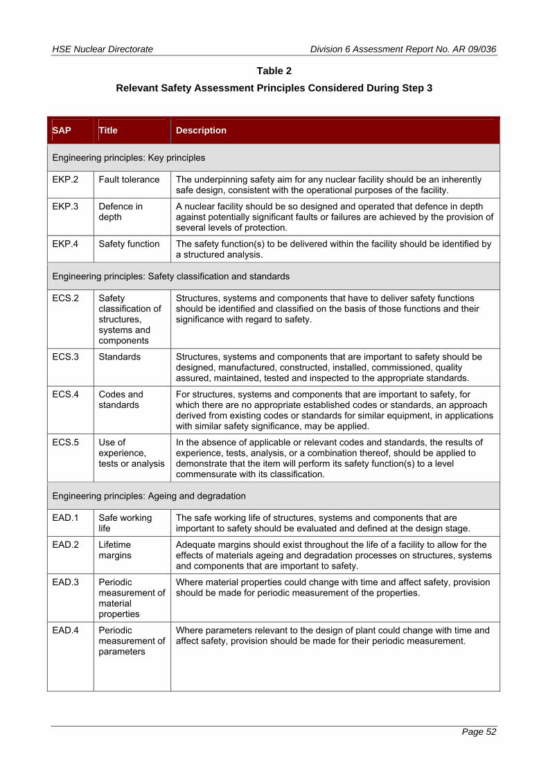
HSE Nuclear Directorate Division 6 Assessment Report No. AR 09/036
Table 2
Relevant Safety Assessment Principles Considered During Step 3
SAP Title Description
Engineering principles: Key principles
EKP.2 Fault tolerance The underpinning safety aim for any nuclear facility should be an inherently safe design, consistent with the operational purposes of the facility.
EKP.3 Defence in depth
A nuclear facility should be so designed and operated that defence in depth against potentially significant faults or failures are achieved by the provision of several levels of protection.
EKP.4 Safety function The safety function(s) to be delivered within the facility should be identified by a structured analysis.
Engineering principles: Safety classification and standards
ECS.2 Safety classification of structures, systems and components
Structures, systems and components that have to deliver safety functions should be identified and classified on the basis of those functions and their significance with regard to safety.
ECS.3 Standards Structures, systems and components that are important to safety should be designed, manufactured, constructed, installed, commissioned, quality assured, maintained, tested and inspected to the appropriate standards.
ECS.4 Codes and standards
For structures, systems and components that are important to safety, for which there are no appropriate established codes or standards, an approach derived from existing codes or standards for similar equipment, in applications with similar safety significance, may be applied.
ECS.5 Use of experience, tests or analysis
In the absence of applicable or relevant codes and standards, the results of experience, tests, analysis, or a combination thereof, should be applied to demonstrate that the item will perform its safety function(s) to a level commensurate with its classification.
Engineering principles: Ageing and degradation
EAD.1 Safe working life
The safe working life of structures, systems and components that are important to safety should be evaluated and defined at the design stage.
EAD.2 Lifetime margins
Adequate margins should exist throughout the life of a facility to allow for the effects of materials ageing and degradation processes on structures, systems and components that are important to safety.
EAD.3 Periodic measurement of material properties
Where material properties could change with time and affect safety, provision should be made for periodic measurement of the properties.
EAD.4
Periodic measurement of parameters
Where parameters relevant to the design of plant could change with time and affect safety, provision should be made for their periodic measurement.
Page 52

HSE Nuclear Directorate Division 6 Assessment Report No. AR 09/036
Page 53
SAP Title Description
Engineering principles: Layout
ELO.3
Obsolescence A process for reviewing the obsolescence of structures, systems and components important to safety should be in place.
Engineering principles: External and internal hazards
EHA.13 Fire, explosion, missiles, toxic gases etc – use and storage of hazardous materials
The on-site use, storage or generation of hazardous materials should be minimised, and controlled and located so that any accident to, or release of, the materials will not jeopardise the establishing of safe conditions on the facility.
Engineering principles: Pressure systems
EPS.2 Flow limitation Flow limiting devices should be provided to piping systems that are connected to or form branches from a main pressure circuit, to minimise the consequences of postulated breaches.
EPS.3 Pressure relief Adequate pressure relief systems should be provided for pressurised systems and provision should be made for periodic testing.
EPS.4 Overpressure protection
Overpressure protection should be consistent with any pressure-temperature limits of operation.
EPS.5 Discharge routes
Pressure discharge routes should be provided with suitable means to ensure that any release of radioactivity from the facility to the environment is minimised.
Engineering principles: Integrity of metal components and structures
EMC.2 Use of scientific and technical issues
The safety case and its assessment should include a comprehensive examination of relevant scientific and technical issues, taking account of precedent when available.
EMC.16 Contamination The potential for contamination of materials during manufacture and installation should be controlled to ensure the integrity of components and structures is not compromised.
EMC.21 Safe operating envelope
Throughout their operating life, safety-related components and structures should be operated and controlled within defined limits consistent with the safe operating envelope defined in the safety case.
Engineering principles: Safety systems
ESS.1 Requirement for safety systems
All nuclear facilities should be provided with safety systems that reduce the frequency or limit the consequences of fault sequences, and that achieve and maintain a defined safe state.
ESS.2
Determination of safety system requirements
The extent of safety system provisions, their functions, levels of protection necessary to achieve defence in depth and required reliabilities should be determined.
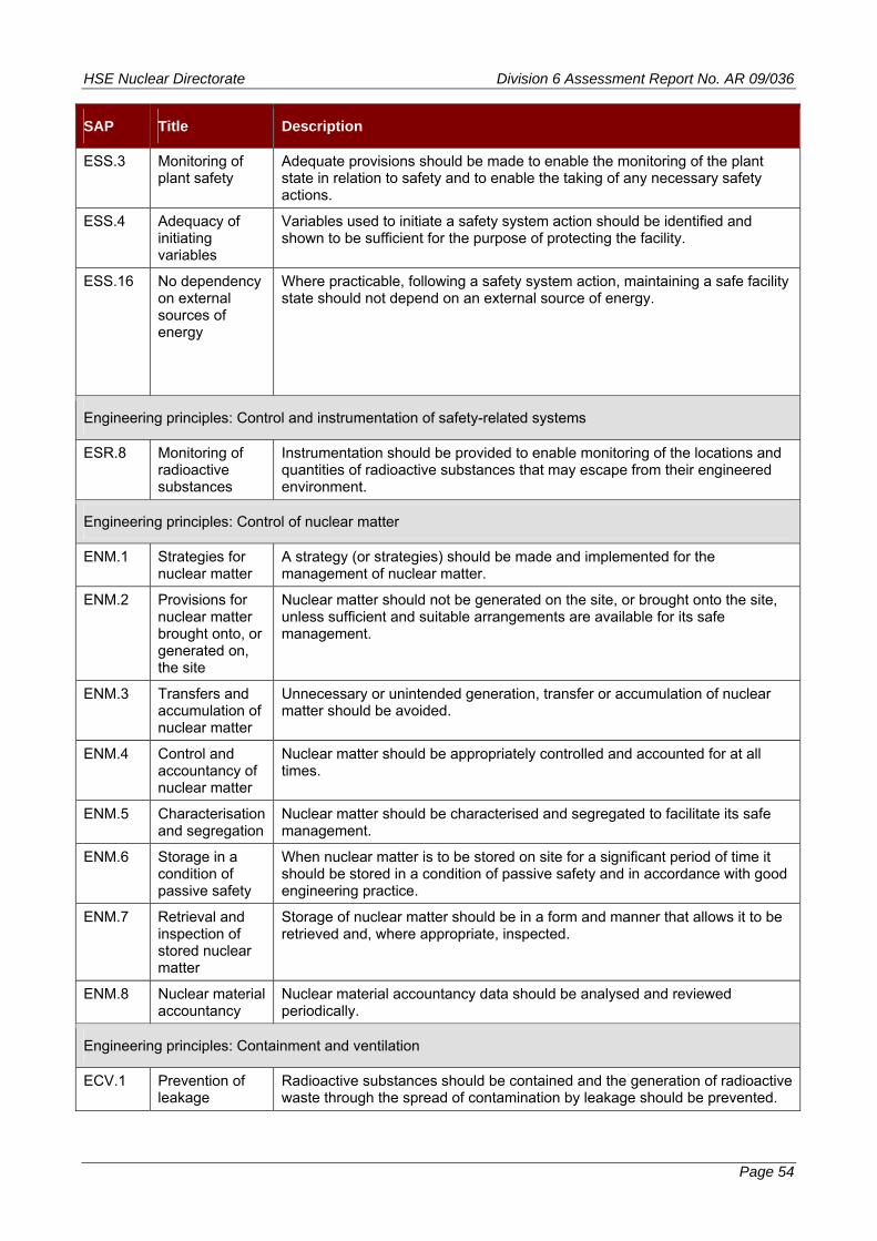
HSE Nuclear Directorate Division 6 Assessment Report No. AR 09/036
Page 54
SAP Title Description
ESS.3 Monitoring of plant safety
Adequate provisions should be made to enable the monitoring of the plant state in relation to safety and to enable the taking of any necessary safety actions.
ESS.4 Adequacy of initiating variables
Variables used to initiate a safety system action should be identified and shown to be sufficient for the purpose of protecting the facility.
ESS.16
No dependency on external sources of energy
Where practicable, following a safety system action, maintaining a safe facility state should not depend on an external source of energy.
Engineering principles: Control and instrumentation of safety-related systems
ESR.8 Monitoring of radioactive substances
Instrumentation should be provided to enable monitoring of the locations and quantities of radioactive substances that may escape from their engineered environment.
Engineering principles: Control of nuclear matter
ENM.1 Strategies for nuclear matter
A strategy (or strategies) should be made and implemented for the management of nuclear matter.
ENM.2 Provisions for nuclear matter brought onto, or generated on, the site
Nuclear matter should not be generated on the site, or brought onto the site, unless sufficient and suitable arrangements are available for its safe management.
ENM.3 Transfers and accumulation of nuclear matter
Unnecessary or unintended generation, transfer or accumulation of nuclear matter should be avoided.
ENM.4 Control and accountancy of nuclear matter
Nuclear matter should be appropriately controlled and accounted for at all times.
ENM.5 Characterisation and segregation
Nuclear matter should be characterised and segregated to facilitate its safe management.
ENM.6 Storage in a condition of passive safety
When nuclear matter is to be stored on site for a significant period of time it should be stored in a condition of passive safety and in accordance with good engineering practice.
ENM.7 Retrieval and inspection of stored nuclear matter
Storage of nuclear matter should be in a form and manner that allows it to be retrieved and, where appropriate, inspected.
ENM.8 Nuclear material accountancy
Nuclear material accountancy data should be analysed and reviewed periodically.
Engineering principles: Containment and ventilation
ECV.1 Prevention of leakage
Radioactive substances should be contained and the generation of radioactive waste through the spread of contamination by leakage should be prevented.

HSE Nuclear Directorate Division 6 Assessment Report No. AR 09/036
Page 55
SAP Title Description
ECV.2 Minimisation of releases
Nuclear containment and associated systems should be designed to minimise radioactive releases to the environment in normal operation, fault and accident conditions.
ECV.3 Means of confinement
The primary means of confining radioactive substance should be by the provision of passive sealed containment systems and intrinsic safety features, in preference to the use of active dynamic systems and components.
ECV.6 Monitoring devices
Suitable monitoring devices with alarms and provisions for sampling should be provided to detect and assess changes in the stored radioactive substances or changes in the radioactivity of the materials within the containment.
ECV.7 Leakage monitoring
Appropriate sampling and monitoring systems and other provisions should be provided outside the containment to detect, locate, quantify and monitor leakages of nuclear matter from the containment boundaries under normal and accident conditions.
ECV.8 Minimisation of provisions
Where provisions are required for the import or export of nuclear matter into or from the facility containments, the number of such provisions should be minimised.
Engineering principles: Reactor core
ERC.1 Design and operation of reactors
The design and operation of the reactor should ensure the fundamental safety functions are delivered with an appropriate degree of confidence for permitted operating modes of the reactor.
ERC.4 Monitoring of safety-related parameters
The core should be designed so that safety-related parameters and conditions can be monitored in all operational and design basis fault conditions and appropriate recovery actions taken in the event of adverse conditions being detected.
Engineering principles: Heat transport systems
EHT.1 Design Heat transport systems should be designed so that heat can be removed or added as required.
EHT.2 Coolant inventory and flow
Sufficient coolant inventory and flow should be provided to maintain cooling within the safety limits for operational states and design basis fault conditions.
EHT.4 Failure of heat transport system
Provisions should be made in the design to prevent failure of the heat transport system that could adversely affect the heat transfer process, or safeguards should be available to maintain the facility in a safe condition and prevent any release in excess of safe limits.
EHT.5 Minimisation of radiological doses
The heat transport system should be designed to minimise radiological doses.
Fault analysis
FA.2 Identification of initiation faults
Fault analysis should identify all initiating faults having the potential to lead to any person receiving a significant dose of radiation, or to a significant quantity of radioactive material escaping from its designated place of residence or confinement.
FA.8 Calculation methods
Calculational methods used for the analyses should adequately represent the physical and chemical processes taking place.
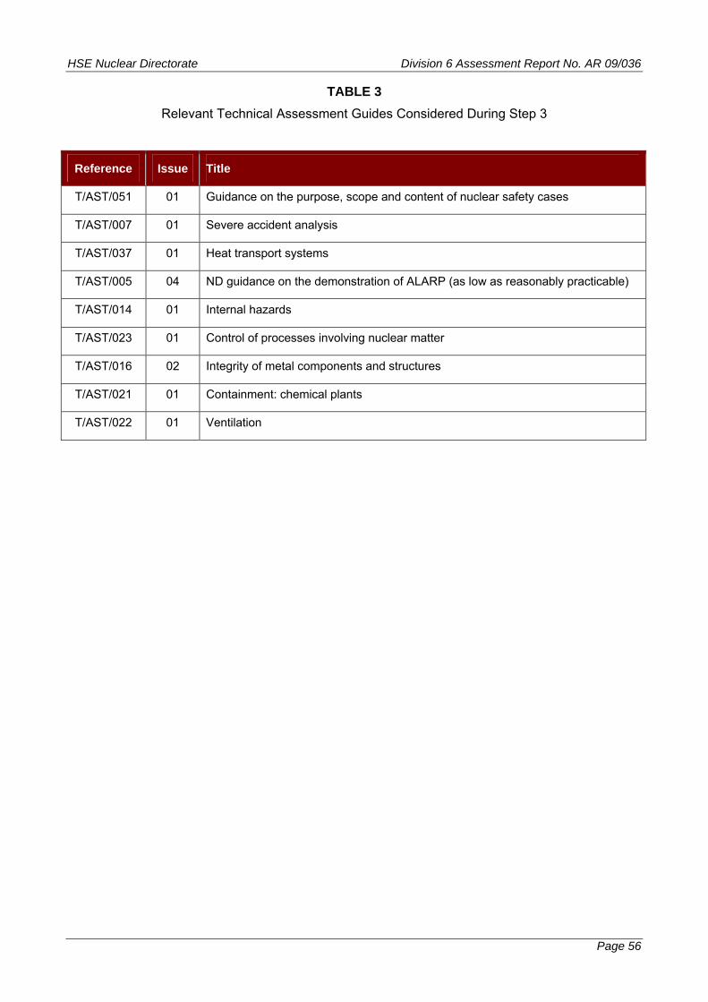
HSE Nuclear Directorate Division 6 Assessment Report No. AR 09/036
TABLE 3
Relevant Technical Assessment Guides Considered During Step 3
Reference Issue Title
T/AST/051 01 Guidance on the purpose, scope and content of nuclear safety cases
T/AST/007 01 Severe accident analysis
T/AST/037 01 Heat transport systems
T/AST/005 04 ND guidance on the demonstration of ALARP (as low as reasonably practicable)
T/AST/014 01 Internal hazards
T/AST/023 01 Control of processes involving nuclear matter
T/AST/016 02 Integrity of metal components and structures
T/AST/021 01 Containment: chemical plants
T/AST/022 01 Ventilation
Page 56
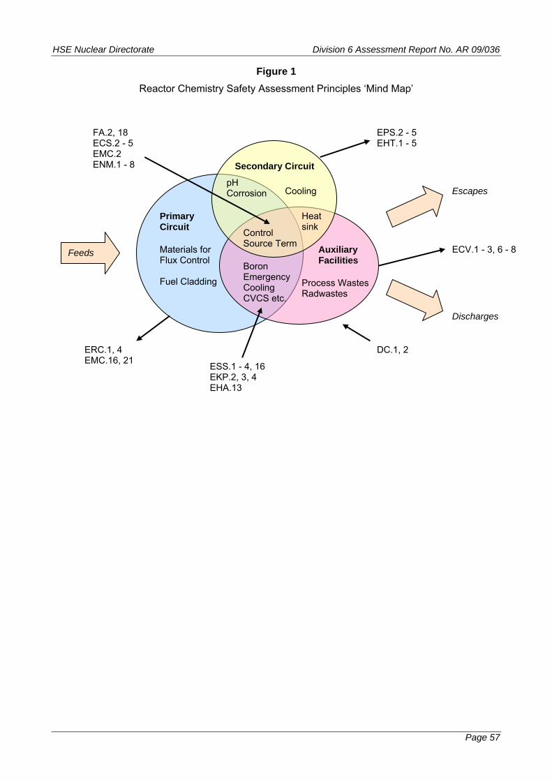
HSE Nuclear Directorate Division 6 Assessment Report No. AR 09/036
Figure 1
Reactor Chemistry Safety Assessment Principles ‘Mind Map’
Secondary Circuit
Primary Circuit
Auxiliary Facilities
pH Corrosion Cooling
Heat sink
Control Source Term
Boron Emergency Cooling CVCS etc.
Process Wastes Radwastes
Materials for Flux Control Fuel Cladding
Feeds
Escapes
Discharges
FA.2, 18 ECS.2 - 5 EMC.2
ECV.1 - 3, 6 - 8
ENM.1 - 8
EPS.2 - 5 EHT.1 - 5
ERC.1, 4 DC.1, 2 EMC.16, 21
ESS.1 - 4, 16 EKP.2, 3, 4 EHA.13
Page 57

HSE Nuclear Directorate Division 6 Assessment Report No. AR 09/036
Annex 1 - Page 1
Annex 1 – Reactor Chemistry – Status of Regulatory Issues and Observations
RI / RO Identifier Date Raised Title Status
Required timescale
(GDA Step 4 / Phase 2)
Regulatory Issues
None
Regulatory Observations
None