generic diagnosis instrument for sofc systems (245128)
TRANSCRIPT

GENeric diagnosis Instrument for SOFC Systems (245128)
Philippe MOÇOTÉGUY EIFER/Project Manager
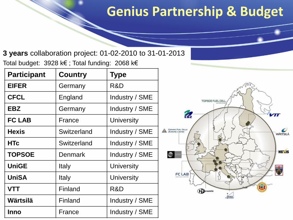
Genius Partnership & Budget
3 years collaboration project: 01-02-2010 to 31-01-2013
Total budget: 3928 k€ ; Total funding: 2068 k€
Participant Country Type
EIFER Germany R&D
CFCL England Industry / SME
EBZ Germany Industry / SME
FC LAB France University
Hexis Switzerland Industry / SME
HTc Switzerland Industry / SME
TOPSOE Denmark Industry / SME
UniGE Italy University
UniSA Italy University
VTT Finland R&D
Wärtsilä Finland Industry / SME
Inno France Industry / SME

Develop a “GENERIC” diagnosis approach that all SOFC developers could use and implement it in their systems according to their specific constraints:
only using process values (normal measurements and system control input parameters).
taking into account “on line” or "off-line“ situations.
Objectives & Outcomes
Steps:
Testing stacks & systems from 4 manufacturers, using commonly defined test plan based on “Design Of Experiment” methodology.
Developing a diagnostic protocol integrating the best algorithm(s).
Validate it (them) on 3 SOFC systems, either off-line or on-line.
4 academic institutions will evaluate 3 types of algorithms (based on signal treatment and on residuals determination from either black box or grey box models) to define the optimal tool(s) for fault detection and identification.
Iteratively adapting the defined test plan according to algorithm developers’ needs.

Diagnostic Methodology
Detection
Process
DEVICE
+ -
Estimated Output
Fault
Identification
Normal operation
Detection Algorithms
Pattern recognition
algorithms
Physical/GB/BB
Models
Residual based
algorithms
Indicators
Residuals
Raw Data
Controller
Corrective or
Mitigative
Actions
Faulty operation
Operating Parameters
&
Responses
Detection

Selection of N parameters to be studied and their
operating range
Selection of responses to be measured
DoE methodology
Reduced centred parameters
Determination of directly impacting parameters
(screening)
Determination of influent interactions between influent parameters
>3 experiments in the centre of the domain so as to:
o Evaluate measurement's reproducibility effect significance.
o Detect potential ageing during experiment.
N+1 ≤ nexp = 2p

-200
-150
-100
-50
0
50
100
coef
f P el [W
]
-100
0
100
200
300
400
500
600
700
coef
f P th
[W]
Results of DoE
PNG T Ustack CPO
3rd & 4th level interactions
System supplier : Hexis
Measurements: EIFER

WP 3: DoE analysis of stack voltage
(VTT experiments on HTc stack)
-600
-500
-400
-300
-200
-100
0
100
200
300
regre
ss c
oeff V
sta
ck [m
V]
Tfurnace FU
Tfurnace
* j
Tfurnace
*FU
Tfurnace
*CPO
j * FU
j*CPO
FU * CPOj
CPO
4th level
interaction
3rd level
interactions
Stack supplier : HTc
Measurements: VTT

Residual based diagnostic approach
Fault tree analysis
Inference
Stack fault
Electrolyte
electrode
delamination
Oxide layer
growth between
interconnect and
cathode
Rib
detachment
Seal failure
Increased thermal
gradient
Local shortage
of fuel
Anode
oxidation
Increase in cell
Ohmic resistanceOverheating
Temperature
controller failure
Increase
in stack
temperature
1 2
Decrease
in stack
voltage
Decrease
in stack
power
Temporany
increase in stack
temperature
Decrease
in stack
voltage
Decrease
in stack
power
Increase in air
temperature at
cathode outlet
Increase in gas
temperature at
anode outletTemp.
controller (1)
Post-
burner (1)
Temperature
controller
Increase in stack
temperature
Decrease in stack
temperature
Increase in
flow air mass
at compressor
outlet
Increase in
compressor
power
Decrease
in net stack
power
Increase of
air excess (λ)
at stack
Decrease in
flow air mass
at compressor
outlet
Increase in
compressor
power
Decrease
in net stack
power
Decrease of
air excess (λ)
at stack
1 2
Post
burner fault
(2)
Post
burner fault
(1)
Increase in
flow air
temperature at
pre-heater
outlet
Decrease in
flow air
temperature at
pre-heater
outlet
Fault
Symptoms (measured values)
s1 s2 s3 s4 s5 s6 s7 s8 s9 s10 s11 s12 s13 s14 s15 s16 s17
f1 0 1 1 0 1 1 1 1 0 1 0 0 0 0 0 1 1
f2 0 1 1 0 0 0 0 0 1 0 0 0 0 0 0 0 0
f3 0 1 1 0 1 1 0 1 0 1 0 0 0 0 0 1 1
f4 0 1 1 0 0 0 0 1 0 1 0 0 0 0 0 0 0
f5 0 1 1 0 0 0 0 1 0 0 0 0 0 0 0 0 0
f6 1 1 1 0 1 1 0 1 0 0 1 1 1 0 0 1 1 Threshold definition (e.g.: ± 2 , ± 3)
Black/grey box Model
Signature matrix
At least one
match
No match
Residual calculation
Uniquematch

Residual based algorithm performance
1000 2000 3000 4000 5000 6000 7000 800015
20
25
30
35
40
45
50
55
Sta
ck V
oltage [
V]
time [min]
measured
simulated
Stack supplier : TopSoE
Measurements: TopSoE
Simulations: Black box model (UniSA)
Simulations: Grey box model (UniGE)

SOFC System (BoP part)
SOFC stack as a sensor
Wavelet Based Diagnosis
SOFC failure
BoP Fault
No Fault
Bayesian Network Based
Diagnosis
Fault Type
Function:
1. Check the state of health of a “special” sensor – SOFC stack;
2. BoP fault detection.
Principle:
Decompose the SOFC voltage signal by wavelet transform method. The distribution of energies of the subsignals can indicate the state of health and the abnormal operating condition of the SOFC.
This algorithm has been validated on data from both test rounds at VTT on HTc stack (requested signal sampling rate is at least 1Hz)
Function: BoP fault identification.
Principle:
Use experimental data to train the Bayesian Network and obtain a meta-model of SOFC. Use this model to estimate the operating variables – Fuel & Air flow rates and utilisations, Furnace & Stack temperatures.
Fault to diagnose: Low current density and high FU.
Validation result: (VTT data)
67% of the1449 samples measured in such a faulty operating mode can be identified by the Bayesian Network model.
Pattern recognition based algorithm performance

"The aim will be to deliver (…) reliable control and diagnostics tools both at a component and at system level.“ "Applied research activities are directed towards developing components and sub-systems with improved performance, durability and cost (…)."
Main project objective: develop a Generic diagnostic algorithm integrated in a standard hardware equipment to detect faults and prevent failure before occurrence. better system reliability increase system lifetime.
Alignment to MAIP- AA3 & AIP 2008 – Topic 3.3

Alignment to MAIP- AA3 & AIP 2008 – Topic 3.3
“(…), substantial effort is needed to address lifetime requirements of 40,000 h for cell
and stack, as well as competitive costs..."
The approach will allow to detect faults and to prevent failure before their occurrence
better system reliability improve the competitiveness of fuel cell vs other µ-
CHP technologies by increasing availability ratio & system lifetime.
“Improved prediction and avoidance of failure mechanisms”.
“Development of strategies for recovery of cell and stack performance”
Experimental evaluation of failure mechanisms’ signatures & development of new data analysis methods identify the effect of each failure mechanism from normal base-line early detection system operating parameters optimisation degradation minimisation.

Organisation of workshops: • Workshop in Viterbo (M19) about degradation causes and effect. • Common workshop with D-CODE project (M28) in Belfort: 10 speakers, 50 attendees.
Cross-cutting issues: Education, Training & Dissemination
Publications & Communications: • 2 publications. • 3 presentations at conferences. • 2 presentations in workshops.
Website: http://genius-jti-project.eu/
Education & Training: • 4 PhD students working on the project, 2 of them spent/are spending time at
partners facilities. • 1 PhD defended (P. de VASCONCELLOS CARDONE, UniGE, 04/2012), 1 to be
defended (K. Wang, FC Lab-EIFER)
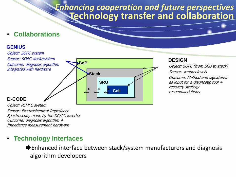
• Collaborations
Enhancing cooperation and future perspectives Technology transfer and collaboration
• Technology Interfaces
Enhanced interface between stack/system manufacturers and diagnosis algorithm developers
BoP
Stack
SRU
Cell
DESIGN
Object: SOFC (from SRU to stack)
Sensor: various levels
Outcome: Method and signatures as input for a diagnostic tool + recovery strategy recommandations
Object: SOFC system
Sensor: SOFC stack/system
Outcome: diagnosis algorithm integrated with hardware
GENIUS
Object: PEMFC system
Sensor: Electrochemical Impedance Spectroscopy made by the DC/AC inverter Outcome: diagnosis algorithm + Impedance measurement hardware
D-CODE

SAPPHIRE
Prognostics / adaptative control
AA 1
AA 4
Automotive Early Markets
PEM D-CODE
Electrolysis AA 2
GENIUS Solid oxyde
diagnostic
Stationary
Fuel cells AA 3
Future perspectives: Generalization to all FC and H2 technologies and AA