geochemistry volume 4 geophysics geosystems · genovesa ridge was the focus of detailed multibeam...
TRANSCRIPT

Genovesa Submarine Ridge: A manifestation of plume-ridgeinteraction in the northern Galapagos Islands
Karen S. HarppDepartment of Geology, Colgate University, Hamilton, New York 13346, USA ([email protected])
Daniel J. FornariGeology and Geophysics Department, Woods Hole Oceanographic Institution, Woods Hole, Massachusetts 02543, USA
Dennis J. GeistDepartment of Geological Sciences, University of Idaho, Moscow, Idaho 83844, USA
Mark D. KurzMarine Chemistry and Geochemistry Department, Woods Hole Oceanographic Institution, Woods Hole, Massachusetts02543, USA
[1] Despite its circular coastline and calderas, Genovesa Island, located between the central Galapagos
Platform and the Galapagos Spreading Center, is crosscut by both eruptive and noneruptive fissures
trending NE-SW. The 075� bearing of the fissures parallels that of Genovesa Ridge, a 55 km long volcanic
rift zone that is the most prominent submarine rift in the Galapagos and constitutes the majority of the
volume of the Genovesa magmatic complex. Genovesa Ridge was the focus of detailed multibeam and
side-scan sonar surveys during the Revelle/Drift04 cruise in 2001. The ridge consists of three left stepping
en echelon segments; the abundances of lava flows, volcanic terraces, and eruptive cones are all consistent
with constructive volcanic processes. The nonlinear arrangement of eruptive vents and the ridge’s en
echelon structure indicate that it did not form over a single dike. Major and trace element compositions of
Genovesa Ridge glasses are modeled by fractional crystallization along the same liquid line of descent as
the island lavas, but some of the glasses exhibit higher Mg # than material sampled from the island. Most
of the submarine and the subaerial lavas have accumulated plagioclase. Incompatible trace element
abundances of dredged Genovesa Ridge rocks are lower than the island’s lavas, but ratios of the elements
are similar in the two settings, which suggests that the island and ridge lavas are derived from nearly
identical mantle sources. Glass inclusions in plagioclase phenocrysts from the ridge are compositionally
diverse, with both higher and lower MgO than the matrix glass, indicative of homogenization at shallow
levels. The structural and geochemical observations are best reconciled if Genovesa Ridge did not form in
response to injection of magma laterally from a hot spot-supplied central volcano, like Kilauea’s Puna
Ridge. Instead, Genovesa Ridge and its western extension are the result of passive upwelling directed by
far-field tectonic stresses that are generated by tension across the 91�W transform. The proximity of the
plume causes magmatism in the extensional zones where it would not ordinarily occur.
Components: 13,627 words, 11 figures, 4 tables.
Keywords: rift zone; seamount; submarine lava flow; mantle plume; plume-ridge interaction; helium.
Index Terms: 3045 Marine Geology and Geophysics: Seafloor morphology and bottom photography; 8429 Volcanology:
Lava rheology and morphology; 3640 Mineralogy and Petrology: Igneous petrology.
Received 24 February 2003; Revised 8 July 2003; Accepted 28 July 2003; Published 27 September 2003.
G3G3GeochemistryGeophysics
Geosystems
Published by AGU and the Geochemical Society
AN ELECTRONIC JOURNAL OF THE EARTH SCIENCES
GeochemistryGeophysics
Geosystems
Article
Volume 4, Number 9
27 September 2003
8511, doi:10.1029/2003GC000531
ISSN: 1525-2027
Copyright 2003 by the American Geophysical Union 1 of 27

Harpp, K. S., D. J. Fornari, D. J. Geist, M. D. Kurz, Genovesa Submarine Ridge: A manifestation of plume-ridge
interaction in the northern Galapagos Islands, Geochem. Geophys. Geosyst., 4(9), 8511, doi:10.1029/2003GC000531, 2003.
————————————
Theme: Plume-Ridge Interacton Guest Editor: David Graham
1. Introduction
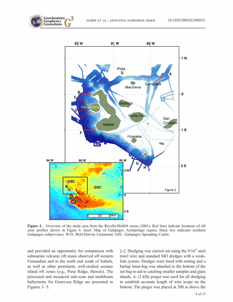
[2] The northern subprovince of the Galapagos
Archipelago is a 100–200 km wide swath bounded
by the main Galapagos Platform to the south and
the Galapagos Spreading Center (GSC) to the north
(Figures 1 and 2). This area is one of the few on the
globe subject to the simultaneous influence of both
plume and ridge related mantle processes without
being dominated by either phenomenon. In the past
�10 My, the plume-ridge system has evolved from
a ridge-centered hot spot to its current configura-
tion, with the GSC located 100–200 km north of
the hot spot center (Figure 1) [Wilson and Hey,
1995]. Studies of submarine lavas erupted along
the GSC have provided geochemical evidence for
extensive plume-ridge interaction [e.g., Verma and
Schilling, 1982; Verma et al., 1983; Schilling et al.,
1982; Detrick et al., 2002]. Subaerial and subma-
rine lavas from the Galapagos Archipelago indicate
that the plume is in turn strongly influenced by the
GSC, resulting in a heterogeneous distribution of
plume material in the upper mantle throughout the
region [e.g., Geist et al., 1988; White et al., 1993;
Kurz and Geist, 1999; Harpp and White, 2001].
[3] The GSC is currently migrating to the northeast
at �50 km/my, away from the hot spot [Wilson and
Hey, 1995; Gripp and Gordon, 1990, 2002]. The
large transform fault at 91�W began to form at
�2.6 Ma [Wilson and Hey, 1995]. Since that time,
the ridge segment closest to the archipelago has
undergone several southward jumps [Wilson and
Hey, 1995], prolonging the proximity of the ridge
to the plume [e.g., Small, 1995].
[4] The islands and seamounts of the northern
Galapagos Archipelago do not lie downstream in
terms of absolute plate motion from the hot spot
center (thought to be in the vicinity of Fernandina
Island [e.g., Toomey et al., 2001; Kurz and Geist,
1999] (Figure 1) and consequently cannot be the
products of plume activity in the traditional sense.
Furthermore, the complex seafloor morphology
[Christie and Fox, 1990], wide range of geochem-
ical compositions [e.g., Harpp and White, 2001],
and lack of systematic alignments of seafloor or
island features with absolute or relative plate
motion [e.g., Harpp and Geist, 2002] (Figure 1)
suggest that the northern Galapagos volcanoes are
not conventional near-ridge seamounts either.
Instead, processes resulting from the far-field tec-
tonic interaction between the plume and the ridge
are the primary factors controlling the style and
distribution of volcanic activity in the northern
Galapagos [Harpp et al., 2002; Harpp and Geist,
2002]. A detailed examination of volcanic struc-
tures in the region between the Galapagos plume
and ridge has the potential to reveal important
information about plume-ridge interaction and the
dynamics of ridge migration processes near
plumes.
[5] During the 2001 DRIFT04 expedition on R/V
Revelle, we performedmultibeam bathymetricmap-
ping and side-scan sonar surveys using the Univer-
sity of Hawaii’s Mapping Research-1 (MR-1)
system along an east-west profile extending from
�50 km east of Genovesa Island to the northern tip
of Isabela Island. The focus of this survey was the
50 km-long ridge that extends east of Genovesa
Island [Harpp et al., 2002] (Figures 2 and 3),
hereafter referred to as the Genovesa Ridge.
[6] Seafloor imagery revealed that several aspects
of Genovesa Ridge are enigmatic. The 075� trendof the ridge is oblique to both the absolute plate
motion (91�) [Gripp and Gordon, 1990] and plate
spreading relative to the GSC (�189�) [DeMets et
al., 1994]. The submarine ridge is aligned with a
series of large fissures that cross-cut other struc-
tural features of Genovesa Island and that pro-
duced the volcano’s youngest subaerial flows
[Harpp et al., 2002] (Figure 3). West of Genovesa
GeochemistryGeophysicsGeosystems G3G3
harpp et al.: genovesa submarine ridge 10.1029/2003GC000531
2 of 27

Island, another submarine ridge extends toward
Marchena Island, where it bends NW toward
Pinta Island.
[7] Volcanic submarine ridges throughout the
study area differ from those observed in Hawaii,
such as the submarine part of Kilauea’s East Rift
Zone, Puna Ridge [e.g., Fornari et al., 1978;
Lonsdale, 1989; Smith et al., 2002]. On the basis
of morphometric and geochemical data, we pro-
pose that Genovesa Ridge and its western exten-
sion are the result of passive upwelling directed by
far-field tectonic stresses that arise from plume-
ridge dynamics, instead of active supply by later-
ally injected magma from a hot spot-supplied
central volcano, like Kilauea’s Puna Ridge. Our
results further suggest that the seamounts, ridges,
and islands in the Northern Galapagos region serve
as indicators of paleostress fields caused by recent
plume-ridge interactions.
2. Shipboard Data Collection
[8] The MR-1 side scan sonar system is an
11/12 kHz near-surface towed sonar system capa-
ble of ensonifying large areas of seafloor and
collecting coregistered backscatter and phase-
bathymetric data [Rongstadt, 1992; Davis et al.,
1993]. Typically, the width of the side-scan imag-
ery, as controlled by the second multiple return
(�72� from the vertical) is �5 times the water
depth in the deeper parts of the survey area and can
be as wide as �8� in depths shallower than
�1000 m (M. Edwards, personal communication
2002). Because R/V Revelle is equipped with a
Simrad EM-120 multibeam sonar, we used only
multibeam sonar in compiling the bathymetric
maps. MR-1 was operated using an external
trigger to synchronize the transmit cycle with the
Revelle’s EM-120 multibeam sonar. Attempts were
made to optimize EM-120 cycle to allow greatest
possible side scan return. MR-1 pulse width was
adjusted based on water depth and EM-120 cycle
and varied between 2 ms for water depths <1000 m
to 10 ms for depths >3000 m. This resulted
in EM120 system cycles of between 6 and 20 s.
MR-1 was used at full power for all surveying.
[9] The simultaneous collection of MR-1 side
scan sonar data and multibeam data during the
DRIFT04 cruise allowed near real-time production
of detailed side-scan backscatter and bathymetry
maps. Bathymetric data were gridded at 100 m and
side-scan data were gridded at 8 m spacing. This
permitted shipboard identification of zones of
volcanic construction and contact relationships
between structural and volcanic features, as well
as areas of inferred recent activity (e.g., highly
reflective, sparsely sedimented, young lava flows).
The maps were used to identify sample collection
sites, in an attempt to characterize the various
seafloor features.
[10] The primary mapping and sampling were con-
ducted around Fernandina and southern and north-
ern Isabela Island [Fornari et al., 2001; Kurz et al.,
2001]. The mapping conducted northeast and west
of Genovesa Island covers an area of >2,200 km2
Figure 1. Bathymetric map of the northern Galapagos Archipelago (adapted from Smith and Sandwell [1997]).Plate motion vectors for the Nazca and Cocos Plates are from Gripp and Gordon [1990].
GeochemistryGeophysicsGeosystems G3G3
harpp et al.: genovesa submarine ridge 10.1029/2003GC000531
3 of 27
and provided an opportunity for comparison with
submarine volcanic rift zones observed off western
Fernandina and to the north and south of Isabela,
as well as other prominent, well-studied oceanic
island rift zones (e.g., Puna Ridge, Hawaii). The
processed and mosaiced side-scan and multibeam
bathymetry for Genovesa Ridge are presented in
Figures 3–5.
[11] Dredging was carried out using the 9/1600 steel
trawl wire and standard SIO dredges with a weak-
link system. Dredges were lined with netting and a
burlap inner-bag was attached to the bottom of the
net bag to aid in catching smaller samples and glass
shards. A 12 kHz pinger was used for all dredging
to establish accurate length of wire scope on the
bottom. The pinger was placed at 200 m above the
Figure 2. Overview of the study area from the Revelle/Drift04 cruise (2001). Red lines indicate locations of riftzone profiles shown in Figure 6. Inset: Map of Galapagos Archipelago region; black box indicates northernGalapagos subprovince; W-D, Wolf-Darwin Lineament; GSC, Galapagos Spreading Center.
GeochemistryGeophysicsGeosystems G3G3
harpp et al.: genovesa submarine ridge 10.1029/2003GC000531
4 of 27

dredge for all sampling operations. Main weak
links were set between �18k–21k with side links
set a 7.5k each. A weight was placed in a burlap
bag for each dredge and tied into the bottom of the
dredge bag to collect glass shards and to minimize
the possibility that the dredge bag would foul
the mouth of the dredge. The bag surrounding
this weight was replaced on every dredge to
avoid contamination. Dredges were run at a ship’s
speed over ground of �1/2 knot using Dynamic
Positioning.
[12] Two dredges were successful along the Gen-
ovesa Ridge, one at the crest of segment B at the
base of a large cone (D22) and the other at the base
of the northern ridge flank (D23; Figures 3–5).
3. Sonar Data Analysis
3.1. Bathymetry
[13] Genovesa Ridge extends �55 km northeast-
ward from the flanks of Genovesa Island. The ridge
consists of a series of three left stepping, en
echelon segments that vary in length from 12 to
over 30 km and are offset by �2 km (segments A,
B, and C, Figures 3–5). West of Genovesa Island,
a fourth en echelon segment (Central Ridge) is
A
Figure 3. Overview of Genovesa Ridge region. (a) EM120 multibeam bathymetric data. (b) MR-1 side-scan sonardata (G: Genovesa Island, P: Pinta Island; M: Marchena Island). White areas in backscatter images have low sonarreflectivity or are in acoustic shadow, while dark regions represent high-reflectivity areas and steep slopes. Dredgelocations are indicated by triangles. Regional contours are from ETOPO2, accessible at http://www.ngdc.noaa.gov/mgg/fliers/01mgg04.html.
GeochemistryGeophysicsGeosystems G3G3
harpp et al.: genovesa submarine ridge 10.1029/2003GC000531
5 of 27

offset more than 4 km in a right step sense, but
current bathymetric coverage is insufficient to
describe this structure in detail (Figure 3).
[14] Segment C forms the northeast tip of the ridge
and is the smallest, deepest segment. It trends 088�,is �13 km long, and overlaps segment B by nearly
5 km. Segment B is 31 km long and has many
cones on its crest. Segment A is 12 km long and
mostly covered by lava flows that cascaded off
Genovesa Island. Segments A and B both trend
075�, overlap by �5 km, and are offset by a 3.5 km
left step. At both of the offsets, the three segments
of Genovesa Ridge curve toward their nearest
neighbor segment (Figures 4 and 5), a characteris-
tic typical of en echelon fractures [e.g., Thomas
and Pollard, 1993; Pollard and Aydin, 1984].
[15] The basal width of Genovesa Ridge ranges
from 30 km for the segment supporting Genovesa
Island to an average of about 10 km. The crest
of the ridge is up to 6 km wide in segment B
(Figure 4). The average axial slopes of the seg-
ments (discounting volcanic vents) are consider-
ably steeper than the mean slope of the entire ridge,
which is �43 m/km (Figure 6 and Table 1). Seg-
ments B and C exhibit convex-up axial profiles
with multiple cones along their crests. Segment A
has concave-up slopes because of the broad plateau
at its crest and fewer flanking cones.
[16] In general, Genovesa Ridge is bounded on its
sides by steep flanks that drop precipitously from
a nearly flat crest, particularly in the wider parts of
the ridge (segments A and B; Figure 4). Genovesa
Ridge is similar to other submarine volcanic
ridges (e.g., Puna, Walvis, and Ninetyeast ridges
[Angevine et al., 1984]) in that its cross-sectional
profiles steepen toward the base. Slopes are gener-
ally greater on the southern flank (360–690 m/km),
B
Figure 3. (continued)
GeochemistryGeophysicsGeosystems G3G3
harpp et al.: genovesa submarine ridge 10.1029/2003GC000531
6 of 27

where the gradient abruptly flattens at 2000–
2100 m water depth. The northern flank is on
average more gently sloping (270–435 m/km),
and the wider segments of the ridge (A and B) have
small terraces below �1500 m depth, accounting
for the lower overall gradients.
[17] West of Genovesa Island, the submarine ridge
continues for �10 km from the shoreline and may
extend �5 km further (‘‘West Genovesa Ridge’’;
Figure 3). West Genovesa Ridge (WGR) is mor-
phologically similar to segment A of Genovesa
Ridge and has a broad crestal plateau and concave-
up flanks; this segment may simply be a westward
extension of segment A.
[18] Northwest of WGR and Genovesa Island, the
much larger submarine Central Ridge trends 088�and has a summit depth of �700 m (Figure 3). This
structure has a similar volume and elevation to
segment B and has a right stepping offset of over
7 km relative to WGR, considerably greater
than the en echelon offsets observed east of the
island. The lack of complete bathymetric coverage
precludes establishing the precise relationship
between the Central Ridge and the platform near
Marchena and Pinta Islands to its west.
[19] The bathymetry swath between Pinta and
Marchena Islands indicates that a broad, �30 km
wide, NW-SE trending submarine platform con-
nects them. North of Marchena, the platform
extends �7 km from the shoreline to the 800 m
isobath before the slope steepens abruptly to
�1300 m depth. The western part of the Mar-
chena-Pinta platform has a number of NW-SE
structural lineations that are observed in both the
bathymetry and side-scan images, which align with
the subaerial fissures on Pinta Island [e.g., Cullen
and McBirney, 1987] (Figure 3). On the northeast
part of the platform, several elongate bathymetric
highs reach >3 km in length, parallel to the NW-SE
strike of the platform as well as the structural
trends on Pinta Island [Cullen and McBirney,
1987]. The minimum depth of �500 m in this area
occurs on what may be the distal end of a rift zone
ridge that extends from Pinta’s southern cape, but
Figure 4. Bathymetry of Genovesa Ridge. Gray lines mark the crests of the en echelon ridge segments A, B, and C,which are labeled with black capital letters. Smaller, black letter ‘‘C’’s are located adjacent to each of the three mostprominent crestal cones of segment B. Black lines across Genovesa Island represent the fissures that crosscut theisland [Harpp et al., 2002] (see text for explanation). Contour interval is 100 m.
GeochemistryGeophysicsGeosystems G3G3
harpp et al.: genovesa submarine ridge 10.1029/2003GC000531
7 of 27

Figure 5. MR-1 side-scan sonar image of Genovesa Ridge. White areas in backscatter images have low sonarreflectivity or are in acoustic shadow, while dark regions represent high-reflectivity areas and steep slopes. Gray linesmark the crests of the en echelon ridge segments A, B, and C. F1 and F2 refer to the large flow fields discussed in thetext; labels are located within the flow fields themselves. Flow field F2 bifurcates and cascades both to the north andsouth between the large crestal cones of segment B, whereas F1 extends northward down the slope of the island ontothe adjacent seafloor plain and extends for nearly 19 km. L1, L2, and L3 are lineations discussed in the text and arelocated beneath and south of their label. White letter ‘‘C’’s are located adjacent to each of the three most prominentcrestal cones of segment B.
Figure 6. Axial profiles of Genovesa Ridge (A), Kilauea’s Puna Ridge, and other Galapagos Archipelago ridges(see Figure 2 for locations of profiles). The valleys in the Genovesa Ridge profile correspond to the regions of overlapbetween segments A, B, and C.
GeochemistryGeophysicsGeosystems G3G3
harpp et al.: genovesa submarine ridge 10.1029/2003GC000531
8 of 27

nearshore bathymetry coverage is missing. Along
the SW edge of the platform and below 2000 m
depth, the gradient decreases sharply where it
meets what may be a series of large terraces similar
to those observed south and west of Isabela Island
[Fornari et al., 2001; Kurz et al., 2001].
3.2. Side-Scan Sonar and Descriptionof Volcanic Features
[20] MR-1 side-scan sonar imagery from the
Genovesa Ridge area is characterized by a wide
range in reflectivities, as well as textural complex-
ities (Figures 3b and 5), including (1) acoustically
smooth, sediment-covered areas north and south of
Genovesa Ridge, as well as SW and east of the
Marchena-Pinta platform; (2) mottled (patchy,
high and low) backscatter areas; and (3) regions
of high backscatter that encompass the steep slopes
and crest of the ridge where lava flow fronts and
cones are dominant.
3.2.1. Lava Flows
[21] Two broad categories of lava flows are
observed along Genovesa Ridge. The first type
covers most of the ridge and consists of small,
lobate structures with reflectivities that vary over
short distances (<10 m), likely indicative of a
range in weathering, sediment cover, or flow-top
morphology (Figure 5). In general, the lobes are
better defined on the north flank than they are to the
south, where the steeper slopes may inhibit their
formation. The sonar imagery is more difficult to
interpret on the south flank, however, because of the
overall strong backscatter from the steep slopes. At
Table 1. Comparison of Genovesa, Puna, and Fernandina Ridge Characteristics
Genovesa Ridge Puna Ridge Fernandina NW Rift
Length �50 km(longer if include WGR)
75 kma 12.7 km
Width 20 km at widest point�10 km in most places
>40 kmb 8 km
Overall trend 075� 065�a Main ridge 310�(curves to N)
Height from seafloor <2000 m relief >4000 m reliefa >3000 m reliefOverall gradient alongaxis
43 m/kmNo continuous crestline slopefor length of ridge due to enechelon structure; highlyvariable slopes.
73 m/kma Even crestlinec 161 m/km (enhancedby location at leadingedge of platform); evencrestline
Depth at which along axisgradient increases
1000 m (�2/3 along ridgefrom island)
2700 ma(�2/3 alongridge from island)
1700 m (�2/3 alongridge from island)
Flank slopes 270–693 m/km 160–275 m/kmd, e 282–1245 m/kmOffsets along ridge Between segments A, B, C,
and D; left stepping offsets of2 km for A-B and 1.5 km forB-C; left stepping offset of4.5 km for C-D.
1 km right steppingoffset at �2700 m deptha
Linear to 11 km, thenbends to N for remaining1.7 km; no apparent offset
Volcanic cones Up to 250 m high, alignedalong ridge crest of segmentsA and B; significantly feweron C. Cones on flanks are largerand flatter than axial cones.
Up to �140 m high None detectable atcurrent resolution.
Pit craters/grabens No apparent axial graben orsignificant pit craters.
Many pit craters, often>25 m deep, along crestc;nearly continuous grabenstructures along cresta
None detectable atcurrent resolution.
Volumetric relationship ofridge to island
Island is part of one segment;comparable to ridge in volume.
Island is volumetricallydominant relative to ridge
Island is volumetricallydominant relative to ridge.
aSmith et al. [2002].
bClague et al. [1994] (Puna Ridge map USGS).
cLonsdale [1989].
dSmith and Cann [1999].
eFornari et al. [1978].
GeochemistryGeophysicsGeosystems G3G3
harpp et al.: genovesa submarine ridge 10.1029/2003GC000531
9 of 27

the base of the ridge, particularly on the southern
flank, the texture of the flows is rougher than higher
up on the ridge. The apparent roughness may be the
result of talus accumulation at the base of the flank
caused by auto-brecciation of flows on steep slopes,
similar to those observed on the south submarine
flank of Kilauea, Hawaii [e.g., Holcomb et al.,
1988].
[22] The second category of lava flow appears to be
the youngest material on the ridge and is observed
primarily on segments A and B. Those flows are
characterized by expansive regions of high reflec-
tivity that extend down the north flanks of the
ridge onto the surrounding seafloor (Figure 5).
These areas are interpreted as relatively fresh, unse-
dimented lava flows with pillow to lobate mor-
phology, on the basis of their consistently high
backscatter signal, tendril-like plan structure, and
tendency to expand in area down slopes. Typical
examples of these are flow fields F1 and F2,
which cover �170 km2 and 29 km2, respectively
(Figure 5). The resolution of the sonar data limits
our ability to determine whether these flow fields
were produced during single or multiple eruptive
events.
[23] Flow fields F1 and F2 appear to originate from
large cones on the summit of segment B (Figures 5
and 7). The flows overlie less reflective material
and therefore must be younger than the main
structures of segments B and C. The existence of
these flanking flows indicates that the Genovesa
Ridge does not consist exclusively of pillow style
lavas and clastic debris, as has been documented at
other submarine volcanic rift zones [e.g., Moore
and Fiske, 1969]. Genovesa Island, Marchena
Island, and West Genovesa Ridge are also sources
for similar lava flows that are large, widely sepa-
rated, and flat lying compared to those that blanket
the Genovesa Ridge.
[24] West of Marchena, where the ridge trends to
the northwest, the highest sonar reflectivities are
observed in a region midway between Marchena
and Pinta Islands. Despite a relatively gentle slope,
the terrain is hummocky and lacks the well-defined
flow-lobe structures observed along the Genovesa
Ridge. We interpret this area of high reflectivity
between Marchena and Pinta as some of the
youngest lavas in the study area. It is also possible
that the shallow saddle area between the islands
serves to funnel strong bottom currents through
this region, thereby keeping it free from significant
sediment accumulation.
3.2.2. Submarine Terraces
[25] In a detailed morphological study of the Puna
Ridge, Hawaii, Smith et al. [2002] define the
submarine terraces imaged by multibeam sonar
and 120 kHz side-scan sonar as flat features that
are nearly circular in plan, with virtually no relief
on their upslope side. The dimensions of the Puna
Ridge terraces are up to a few kilometers in width
and several hundreds of meters high, and they are
often found as a sequence of overlapping steps.
Some have flat or mildly inflated surfaces, whereas
others may possess summit craters and are thought
to be tube-fed structures.
[26] Genovesa Ridge has similar but smaller terrace
features, particularly along the ridge crest. These
terraces are up to 2 km across and 100 m high. At
the tips of the segments, many exhibit domed
structures (�25 m high). Some of the terraces are
adorned with rows of cones (e.g., east crest of
segment B), comparable to structures Smith et al.
[2002] have interpreted as secondary ‘‘rootless’’
vents above lava tubes that constructed the terraces.
[27] The flows that originate from subaerial vents
on Genovesa and Marchena Island, as well as those
constructing the northern part of West Genovesa
Ridge, form a different type of terrace. Instead,
these terraces are far more extensive, up to about
10 km across. They are morphologically similar to
the submarine terraces between Fernandina and
Cerro Azul volcanoes and south of Isabela and
Floreana Islands [Fornari et al., 2001].
3.2.3. Volcanic Cones
[28] Genovesa Ridge bears numerous cones, which
are concentrated along crests of the ridge segments
and on the lower ridge flanks, below �1900 m
depth. Cones on or near the Genovesa Ridge crest
are taller, more pointed, and have smaller basal
areas than those on the lower flanks. The crestal
GeochemistryGeophysicsGeosystems G3G3
harpp et al.: genovesa submarine ridge 10.1029/2003GC000531
10 of 27
cones range in height from over 250 m down to
�40 m. Their height to basal diameter ratio is
�6–7%, less than is usual for Pacific basin volca-
noes [Smith and Jordan, 1988]. Virtually all the
cones are aligned along the crest of the ridge.
Segment A has fewer cones than the other seg-
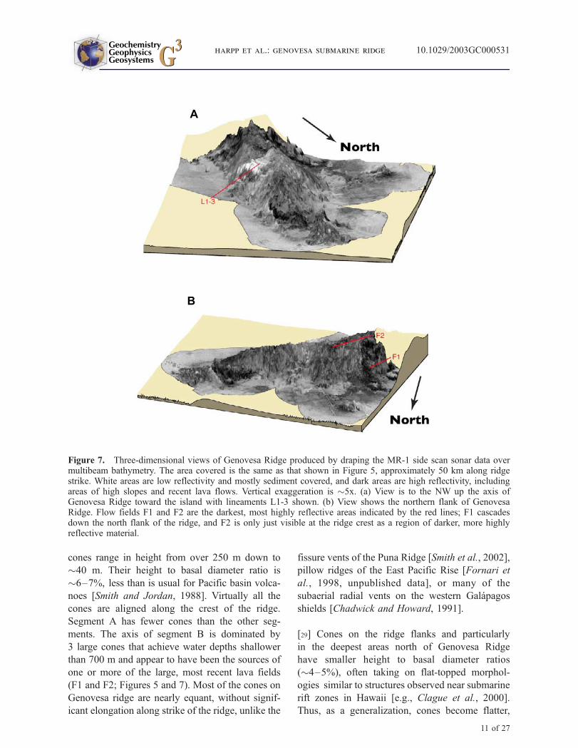
ments. The axis of segment B is dominated by
3 large cones that achieve water depths shallower
than 700 m and appear to have been the sources of
one or more of the large, most recent lava fields
(F1 and F2; Figures 5 and 7). Most of the cones on
Genovesa ridge are nearly equant, without signif-
icant elongation along strike of the ridge, unlike the
fissure vents of the Puna Ridge [Smith et al., 2002],
pillow ridges of the East Pacific Rise [Fornari et
al., 1998, unpublished data], or many of the
subaerial radial vents on the western Galapagos
shields [Chadwick and Howard, 1991].
[29] Cones on the ridge flanks and particularly
in the deepest areas north of Genovesa Ridge
have smaller height to basal diameter ratios
(�4–5%), often taking on flat-topped morphol-
ogies similar to structures observed near submarine
rift zones in Hawaii [e.g., Clague et al., 2000].
Thus, as a generalization, cones become flatter,
A
B
Figure 7. Three-dimensional views of Genovesa Ridge produced by draping the MR-1 side scan sonar data overmultibeam bathymetry. The area covered is the same as that shown in Figure 5, approximately 50 km along ridgestrike. White areas are low reflectivity and mostly sediment covered, and dark areas are high reflectivity, includingareas of high slopes and recent lava flows. Vertical exaggeration is �5x. (a) View is to the NW up the axis ofGenovesa Ridge toward the island with lineaments L1-3 shown. (b) View shows the northern flank of GenovesaRidge. Flow fields F1 and F2 are the darkest, most highly reflective areas indicated by the red lines; F1 cascadesdown the north flank of the ridge, and F2 is only just visible at the ridge crest as a region of darker, more highlyreflective material.
GeochemistryGeophysicsGeosystems G3G3
harpp et al.: genovesa submarine ridge 10.1029/2003GC000531
11 of 27

less tall, but more voluminous with increasing
water depth.
3.2.4. Structural Lineations
[30] A set of nearly linear seafloor features is
observed in the vicinity of 0�220N latitude and
89�470W longitude, on the south flank of Genovesa
Ridge (Figures 5 and 7). The highly reflective
lineations delimit the southern edge of a low
backscatter area corresponding to one of the flattest
expanses on the Genovesa Ridge. The most prom-
inent and sharpest lineations (L1 and L2; Figures 5
and 7) are subparallel to the strike of the ridge
(075�), but are cut by a slightly diffuse lineation
(L3) with a more northerly bearing. Lineations L1
and L2 possess less than 25 m in relief, while L3
coincides with a valley that extends to the NE up a
cliff face.
[31] The lineations likely result from slope failure
similar to unbuttressed landslide collapse observed
off oceanic islands like Hawaii [e.g., Lipman et al.,
1988, 2000]. The correspondence of L3 with the
minor valley is consistent with this hypothesis, as
is the generally higher reflectivity of the lineations
relative to the surrounding material. If rock has
been exposed by downward movement of slump
blocks, reflectivity should be high owing to the
steep face, fresh rock, and lack of sediment accu-
mulation. Similar lineations on the Central Ridge
(Figure 3b) are parallel to each other and define
arcuate traces, reminiscent of slump scars; these
structures are also located in a large, flat area of
low backscatter. In all observed cases, the seafloor
at the base of the ridge beneath the lineations
exhibits rough, hummocky morphology, consistent
with accumulations of slump debris.
[32] The lineations on the platform between Pinta
and Marchena Islands do not form at the top of
steeply sloped ridge flanks. The lack of associated
slump debris and hummocky terrain suggests
Table 2. Major Element Contents of Dredged Lavasa
SiO2 Al2O3 TiO2 FeO MnO CaO MgO K2O Na2O P2O5 SO2 Total
Glassesb
D22-A 48.49 14.93 1.20 9.86 0.18 13.24 8.19 0.05 2.74 0.06 0.12 99.12D22-B 48.15 15.16 1.17 9.86 0.17 13.24 8.28 0.05 2.67 0.07 0.12 98.94D22-C 48.48 14.93 1.19 10.00 0.19 13.27 8.08 0.05 2.72 0.09 0.13 99.12D22-D 47.97 16.37 1.01 8.68 0.16 13.31 9.10 0.06 2.57 0.05 0.27 99.54D22-E 48.45 14.98 1.19 9.87 0.17 13.27 8.08 0.07 2.78 0.07 0.32 99.25D22-F 48.66 14.95 1.20 10.08 0.19 13.18 8.01 0.05 2.76 0.08 0.15 99.32D22-G 48.70 14.91 1.22 10.15 0.19 13.14 7.97 0.06 2.78 0.08 0.15 99.34D22-H 48.58 15.15 1.20 10.10 0.21 13.46 7.79 0.07 2.74 0.07 0.33 99.69D22-I 48.74 15.04 1.17 9.90 0.19 13.22 8.27 0.05 2.76 0.08 0.12 99.53D23-A 49.42 14.72 1.27 10.33 0.18 12.98 7.82 0.06 2.86 0.10 0.14 99.87D23-B 48.83 14.60 1.24 10.37 0.18 12.92 7.71 0.05 2.82 0.09 0.12 98.93D23-C 49.13 14.79 1.24 10.36 0.21 12.89 7.87 0.05 2.84 0.08 0.14 99.6D23-E 49.06 14.66 1.32 10.68 0.20 12.85 7.67 0.06 2.93 0.07 0.15 99.54D23-F 49.13 14.47 1.31 10.63 0.19 12.78 7.61 0.06 2.96 0.09 0.14 99.41D23-G 49.37 14.59 1.25 10.49 0.21 12.95 7.89 0.05 2.87 0.06 0.13 99.86D23-H 49.09 14.51 1.33 10.70 0.20 12.81 7.65 0.06 2.93 0.07 0.14 99.48D22-D Glass Inclusion 1 49.95 14.42 0.82 8.71 0.18 12.62 9.84 0.07 2.48 0.06 0.21 99.36D22-D Glass Inclusion 2 50.12 15.15 0.81 8.40 0.15 12.95 9.60 0.06 2.62 0.01 0.23 100.1D22-D Glass Inclusion 3 50.52 15.96 0.99 7.72 0.13 12.33 8.80 0.05 2.91 0.06 0.18 99.63D22-D Glass Inclusion 4 49.72 14.91 1.08 8.38 0.14 12.40 9.23 0.07 2.66 0.11 0.24 98.95D22-D Glass Inclusion 5 48.97 15.62 0.84 9.36 0.23 12.67 9.36 0.06 2.55 0.08 0.24 100.0D22-D Glass Inclusion 6 48.75 15.32 0.93 9.51 0.18 12.57 9.42 0.09 2.52 0.04 0.27 99.6D22-D Glass Inclusion 7 49.87 14.97 0.77 9.72 0.19 13.04 9.06 0.08 2.08 0.03 0.32 100.1D22-D Glass Inclusion 8 49.14 15.84 0.76 9.30 0.11 13.21 8.52 0.08 2.56 0.07 0.28 99.88
Whole rockc
D22-D 49.77 21.16 0.714 6.02 0.116 12.89 6.86 0.04 1.95 0.046 99.56
aD22 location: dredge on bottom: 0�22.540N, 89�51.420W, 848 m; dredge off bottom: 0�22.480N, 89�51.800W, 779 m. D23 location: dredge on
bottom: 0�29.200N, 89�49.900W, 2257 m; dredge off bottom: 0�28.690N, 89�49.850W, 1995 m.bConcentrations determined by microprobe.
cConcentrations determined by XRF.
GeochemistryGeophysicsGeosystems G3G3
harpp et al.: genovesa submarine ridge 10.1029/2003GC000531
12 of 27

Table 3. Trace Element Contents of Dredge Lavas from Genovesa Ridge
Sc V Cr Co Ni Cu Zn Ga Rb Sr Y Zr Nb Ba
GlassesD22-A 53.2 298 349 49.6 73.6 130 71.4 0.51 105 30.2 67.1 1.04 6.27D22-B 51.8 290 340 51.7 96.4 130 71.5 0.59 109 29.9 67.6 1.28 7.76D22-C 57.4 330 380 54.1 79.4 139 79.0 0.56 112 33.1 75.2 1.14 6.96D22-DD22-E 55.6 317 367 52.1 76.6 135 73.9 0.52 108 32.0 71.5 1.11 6.72D22-F 52.4 294 344 52.3 97.5 130 72.0 0.58 107 29.9 67.4 1.26 7.69D22-G 49.1 275 321 48.9 91.7 121 66.8 0.53 100 27.7 62.8 1.18 7.27D22-H 57.2 316 373 52.8 76.6 133 74.4 0.53 109 32.1 72.1 1.11 6.86D22-I 55.7 309 366 51.5 76.0 133 73.0 0.52 106 31.7 70.7 1.09 6.61D23-A 54.3 330 215 54.2 68.6 129 84.4 0.72 97.8 32.3 66.6 1.15 6.62D23-B 53.7 323 215 53.3 69.5 125 77.3 0.52 95.8 31.6 63.7 1.11 7.43D23-C 53.1 321 209 53.2 65.4 123 75.7 0.51 96.0 31.8 64.8 1.11 6.15D23-E 57.0 339 223 57.2 89.6 123 88.9 0.82 119 34.9 81.1 1.78 25.0D23-F 52.6 313 210 50.3 55.8 120 73.5 0.61 97.4 30.6 68.6 1.33 7.23D23-G 51.2 318 205 51.9 65.9 122 76.9 0.52 98.0 31.8 65.3 1.12 6.35D23-H 51.5 309 201 50.3 55.2 124 76.2 0.66 102 31.6 71.7 1.39 7.72
Whole rockD22-Da 27.0 170 346 42.97 142 105 39.0 15.0 0.34 119 18.0 44.0 1.5 5.99
W-2b 36.5 271 91.7 44.9 72.4 105 75.5 20.0 196 22.8 89.8 7.87 168SD 0.97 9.26 1.94 1.13 2.13 1.93 1.87 0.31 4.54 0.41 1.60 0.11 3.90Count 20 20 20 20 20 20 25 25 10 25 25 25 25
La Ce Pr Nd Sm Eu Gd Tb Dy Ho Er Tm Yb Lu Hf Ta Pb Th U
GlassesD22-A 1.72 6.24 1.26 7.32 2.88 1.10 3.89 0.73 4.80 1.07 3.05 0.45 2.82 0.42 1.83 0.07 0.26 0.07 0.01D22-B 1.86 6.52 1.28 7.31 2.83 1.08 3.80 0.72 4.76 1.05 3.04 0.45 2.80 0.42 1.83 0.08 0.28 0.08 0.02D22-C 1.87 6.81 1.37 7.97 3.13 1.18 4.20 0.79 5.27 1.17 3.35 0.50 3.10 0.47 2.01 0.08 0.30 0.07 0.01
D22-DD22-E 1.84 6.67 1.34 7.77 3.06 1.17 4.16 0.78 5.15 1.14 3.28 0.48 3.02 0.45 1.95 0.07 0.34 0.07 0.01D22-F 1.86 6.50 1.28 7.29 2.81 1.09 3.84 0.72 4.79 1.07 3.06 0.45 2.80 0.42 1.82 0.08 0.27 0.08 0.02D22-G 1.75 6.08 1.19 6.80 2.64 1.02 3.60 0.68 4.49 1.00 2.85 0.42 2.63 0.39 1.70 0.08 0.23 0.08 0.01D22-H 1.83 6.64 1.33 7.73 3.03 1.18 4.16 0.79 5.20 1.15 3.30 0.49 3.04 0.46 1.96 0.07 0.26 0.07 0.07D22-I 1.82 6.59 1.33 7.70 3.04 1.17 4.15 0.78 5.15 1.14 3.27 0.48 3.00 0.45 1.96 0.07 0.29 0.07 0.01D23-A 1.80 6.21 1.25 7.31 2.96 1.15 4.15 0.79 5.22 1.16 3.32 0.50 3.07 0.46 1.90 0.08 0.38 0.08 0.01D23-B 1.72 6.03 1.21 7.11 2.87 1.11 4.01 0.77 5.08 1.13 3.25 0.48 2.99 0.44 1.84 0.07 0.25 0.07 0.01D23-C 1.72 6.07 1.22 7.15 2.86 1.13 4.07 0.78 5.10 1.13 3.25 0.49 3.00 0.45 1.84 0.07 0.24 0.07 0.01D23-E 3.03 8.68 1.58 8.80 3.33 1.26 4.59 0.87 5.68 1.26 3.62 0.54 3.35 0.50 2.19 0.11 1.97 0.14 0.13D23-F 1.96 6.66 1.29 7.34 2.89 1.10 3.98 0.76 4.97 1.10 3.15 0.47 2.89 0.43 1.89 0.09 0.26 0.09 0.02D23-G 1.74 6.15 1.24 7.25 2.95 1.15 4.13 0.79 5.22 1.16 3.32 0.49 3.06 0.46 1.89 0.08 0.24 0.07 0.01D23-H 2.05 6.95 1.36 7.72 3.02 1.16 4.16 0.78 5.19 1.15 3.28 0.49 3.03 0.45 1.98 0.09 0.27 0.09 0.02
Whole rockD22-Da 1.19 3.97 0.78 4.49 1.75 0.74 2.36 0.44 2.91 0.64 1.84 0.27 1.69 0.25 1.12 0.48 0.06 0.02
W-2b 10.4 22.7 3.02 12.7 3.31 1.08 3.66 0.62 3.84 0.81 2.26 0.33 2.04 0.30 2.29 0.48 7.65 2.13 0.50SD 0.22 0.47 0.06 0.26 0.07 0.03 0.08 0.02 0.08 0.02 0.05 0.01 0.04 0.01 0.04 0.01 0.22 0.05 0.02Count 25 25 25 25 25 25 25 25 25 25 25 25 25 25 25 25 25 20 23
aConcentrations of Sc, V, Cr, Ni, Cu, Zn, Ga, Rb, Y, Zr, and Nb in D22-D (whole rock) were determined by XRF. All other elements for D22-D
and all glass concentrations were determined by ICP-MS.bW-2 is a USGS standard reference material analyzed as an unknown for quality control.
GeochemistryGeophysicsGeosystems G3G3
harpp et al.: genovesa submarine ridge 10.1029/2003GC000531
13 of 27
instead that they are fissure vents or noneruptive
fractures.
4. Geochemical Analyses
4.1. Petrography
[33] Dredge 22, taken from �800 m depth along
the crest of segment B of Genovesa Ridge,
included two types of pillow lavas. Sample
D22-D is a plagioclase-ultraphyric basalt, with
15% plagioclase phenocrysts up to 6 mm long,
which is petrographically similar to much of the
subaerial lava from Genovesa Island [Harpp et
al., 2002]. All other specimens collected from
Dredge 22 are sparsely plagioclase-phyric, with
<1% plagioclase phenocrysts up to 2 mm in
length. Dredge 23 was collected from a small
escarpment at the northern base of segment B at a
depth of �2126 m (Figures 3–5). All samples
from this dredge are lithologically identical and
are aphyric pillow lavas with glassy crusts; the
rocks are more altered than those from Dredge 22.
4.2. Analytical Methods
[34] Because almost all dredged lavas are glassy,
only sample D22-D was analyzed by XRF for major
and trace element abundances; all others were
examined by electron microprobe and ICP-MS.
[35] Glass and melt inclusion compositions were
determined on the Cameca Camebax electron
microprobe at Washington State University. Fresh
volcanic glass free of visible alteration was care-
fully hand picked with the aid of a binocular
microscope and doubly rinsed in distilled water.
The glass analyses were made with a beam diam-
eter of 15–20 microns, current of 10 nA, and
potential of 15 kV. A correction for sodium loss
by volatilization was made by monitoring variation
in Na counts with time. Reported values represent
averages of two analyses each of 3–5 separate
glass grains.
[36] Bulk rock analyses were performed by XRF in
the Geoanalytical Laboratory at Washington State
University (D22-D only [Johnson et al., 1999]).
Blind triplicate analyses yielded reproducibility at
levels of <1% RSD for the major analytes and <5%
for the trace elements (Tables 2 and 3).
[37] Trace elements were determined by ICP-MS at
Colgate University. Glass chips were hand picked
to avoid visible alteration, then ultrasonicated in
purified water repeatedly to remove surficial con-
tamination. Between 0.22 and 0.30 g of each
sample were heated in closed Teflon containers
for 48 hours with 25 mL of a 3:2 mixture of
purified HNO3 and HF acids. The solutions were
evaporated to dryness in a HEPA-filtered laminar
flow hood, and subsequently redissolved in 25 mL
of 50% purified HNO3. The solutions were trans-
ferred quantitatively to 250 mL LDPE bottles and
mixed with purified water to achieve a thousand-
fold dilution of the original sample.
[38] Trace element analysis was performed on a
Hewlett Packard HP4500 inductively coupled
plasma-mass spectrometer (Table 3). Samples were
run 4–6 times to yield overall precisions of <2% for
all analyte masses on replicate analyses (except
for Th). Standard curves for each isotope were
constructed using USGS Standard Reference
Materials BIR-1, DNC-1, W-2, BHVO-2, and
AGV-2, yielding Pearson correlation coefficients
consistently >0.998. Instrumental drift was moni-
tored using three internal standard isotopes, 115In,133Cs, and 182W; raw data for each analyte were
corrected to the nearest internal standard mass prior
to calculating final solution concentrations [e.g.,
Eggins et al., 1997].
[39] Helium isotopic measurements were per-
formed in the Isotope Geochemistry Facility at
Woods Hole Oceanographic Institution (Table 4).
All measurements were obtained by in vacuo
crushing of cleaned volcanic glass. The glasses
were lightly crushed in stainless steel mortar and
pestle, and washed in distilled water, nitric acid,
distilled water, and acetone prior to hand picking
under binocular microscope and placement into the
vacuum crushing apparatus (as described by Kurz
et al. [1995]).
4.3. Major and Trace Elements
[40] Lavas from Genovesa Ridge dredges have Mg
# = 56.0 to 65.1 (Mg # = molar MgO/(MgO +
GeochemistryGeophysicsGeosystems G3G3
harpp et al.: genovesa submarine ridge 10.1029/2003GC000531
14 of 27
FeO*)) and are largely indistinguishable from
normal mid-ocean ridge basalt (MORB [e.g.,
Sinton and Detrick, 1992]), with relatively narrow
ranges in major and trace element contents (e.g.,
TiO2: 1.01–1.33 wt. %; Na2O: 2.57–2.96 wt.%;
Figure 8 and Table 2). Similarly, Genovesa Ridge
samples have consistently depleted, MORB-
like incompatible trace element compositions
(Figures 9 and 10 and Table 3). They exhibit
depleted light rare earth element (REE) signatures
with slightly positive heavy REE slopes (i.e.,
Sm/Yb(n) > 1), an indication that they may have
been generated at greater average depths than
typical MORB [e.g., Wilson, 1992]. A similar
pattern is observed in all subaerial lavas collected
from Genovesa Island [Harpp et al., 2002]
(Figure 10).
[41] The whole rock composition of D22-D is
significantly richer in Al2O3 and SiO2 and poorer
in Na2O than glass from the same sample. Glass
inclusions in plagioclase phenocrysts are composi-
tionally more diverse than glass from the quenched
rind, but the average of all the inclusions is close to
that of the rind glass for most major elements
(Figure 8). Lavas from the base of the ridge
(D23) have lower Mg # and higher Na2O, TiO2,
FeO, and SiO2 contents than the lavas from D22.
[42] In contrast to the major elements, incompati-
ble trace element (ITE) concentrations from the
two dredges are nearly indistinguishable (Figures 9
and 10). In particular, most ratios of incompatible
trace elements are identical within analytical error,
confirming that D22 and D23 lavas originated from
similar mantle sources. Slight differences in some
trace element ratios, such as Sm/Yb(n) (Figure 10),
indicate that melting conditions may have varied
slightly with time or in different places.
[43] The trace element variations observed in
Dredge 22 can be explained largely by the effects
of the abundant, accumulated plagioclase pheno-
crysts in D22-D (Figures 9 and 10). Despite the
major element homogeneity of D23 glasses, var-
iations of the more incompatible elements are
greater in D23 glasses than in D22 (e.g., Ba, Zr,
Nb, Rb, Sr). Compared to a detailed compositional
study of single Icelandic lava flows [Slater et al.,
2001], Dredge 23 glasses exhibit up to twice the
variation in light rare earth element and Ba con-
centrations observed in individual Icelandic flows,
but similar or less than half as much variation in
other highly incompatible elements (including Rb,
Xr, Y, Zr, Nb, Ba, and the heavy REEs).
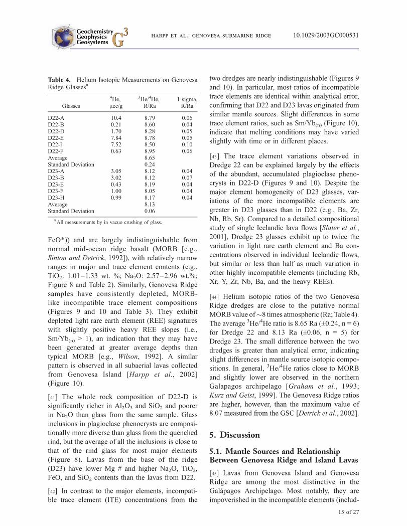
[44] Helium isotopic ratios of the two Genovesa
Ridge dredges are close to the putative normal
MORBvalue of�8 times atmospheric (Ra; Table 4).
The average 3He/4He ratio is 8.65 Ra (±0.24, n = 6)
for Dredge 22 and 8.13 Ra (±0.06, n = 5) for
Dredge 23. The small difference between the two
dredges is greater than analytical error, indicating
slight differences in mantle source isotopic compo-
sitions. In general, 3He/4He ratios close to MORB
and slightly lower are observed in the northern
Galapagos archipelago [Graham et al., 1993;
Kurz and Geist, 1999]. The Genovesa Ridge ratios
are higher, however, than the maximum value of
8.07 measured from the GSC [Detrick et al., 2002].
5. Discussion
5.1. Mantle Sources and RelationshipBetween Genovesa Ridge and Island Lavas
[45] Lavas from Genovesa Island and Genovesa
Ridge are among the most distinctive in the
Galapagos Archipelago. Most notably, they are
impoverished in the incompatible elements (includ-
Table 4. Helium Isotopic Measurements on GenovesaRidge Glassesa
Glasses
4He,mcc/g
3He/4He,R/Ra
1 sigma,R/Ra
D22-A 10.4 8.79 0.06D22-B 0.21 8.60 0.04D22-D 1.70 8.28 0.05D22-E 7.84 8.78 0.05D22-I 7.52 8.50 0.10D22-F 0.63 8.95 0.06Average 8.65Standard Deviation 0.24D23-A 3.05 8.12 0.04D23-B 3.02 8.12 0.07D23-E 0.43 8.19 0.04D23-F 1.00 8.05 0.04D23-H 0.99 8.17 0.04Average 8.13Standard Deviation 0.06
aAll measurements by in vacuo crushing of glass.
GeochemistryGeophysicsGeosystems G3G3
harpp et al.: genovesa submarine ridge 10.1029/2003GC000531
15 of 27

ing Ti, K, and P), closely resemble normal MORB,
and many are ultraporphyritic with large (>1 cm)
plagioclase phenocrysts [Harpp et al., 2002].
Therefore the depleted mantle source that feeds
Genovesa Island [Harpp et al., 2002] is similar or
even identical to that supplying magma to the
submarine ridge, and consists primarily of depleted
upper mantle.
[46] Most of the differences between the subaerial
Genovesa Island and submarine Genovesa Ridge
samples can be attributed to variations in the ana-
lyzed materials [i.e., glass versus whole rock), the
accumulation of plagioclase, and shallow-level frac-
tional crystallization (Figure 8). The compositional
differences between the high-MgO porphyritic
sample D22-D and the aphyric, lower MgO lavas
are likely the result of fractional crystallization of
olivine and plagioclase. Increasing Ca/Al ratios
with evolution (Figure 8) rules out significant
clinopyroxene fractionation, which is important
because clinopyroxene is the liquidus phase in these
compositions at pressures of greater than �1 kb (as
calculated from the MELTS program [Ghiorso and
Sack, 1995]). Most fractionation of the Genovesa
Ridge magmas therefore must have taken place in
the shallow crust, in contrast to magma from
the western Galapagos volcanoes, which undergo
Figure 8. Major element variations in Genovesa Ridge lavas. Comparison of dredged Genovesa glasses (D22 andD23) to subaerial Genovesa Island whole rock analyses from Harpp et al. [2002]. Solid arrow connects D22-D glass(tail of arrow) and whole rock (head of arrow) to illustrate the effect of plagioclase phenocryst addition to the melt.The arrow emanating from Mg # = 56 glass also shows hypothetical plagioclase addition.
GeochemistryGeophysicsGeosystems G3G3
harpp et al.: genovesa submarine ridge 10.1029/2003GC000531
16 of 27

extensive fractional crystallization in the upper
mantle and lower crust [Geist et al., 1998].
[47] Although the major element compositions of
lavas from Genovesa Island and Genovesa Ridge
are similar and appear to be related primarily by
shallow crystallization, subtle differences distin-
guish the two suites. In terms of major elements,
the glass and whole rock major element composi-
tions from sample D22-D are more MgO-rich than
any of the subaerial lavas. For some incompatible
trace elements and their ratios, the most depleted
Genovesa Island lavas and the most enriched
submarine-ridge compositions barely overlap
(e.g., Lan/Smn and Smn/Ybn; Figure 10c). For other
ratios (e.g., Hf/Ta, Zr/Nb, La/Ce), the compositions
are more distinctive. The incompatible element
ratios of most ridge lavas define a trend similar
to that exhibited by the island but extending toward
more depleted compositions (Figure 10c). Other-
wise, the submarine ridge lavas most closely
resemble basalts produced during the island’s ear-
liest shield-building phase [Harpp et al., 2002].
[48] With the limited set of samples and analytical
data, it is not possible to determine whether the
island magmas originate from slightly lower
extents of melting, or whether they are derived
from a slightly less depleted source. The lower
Sm/Yb(n) and elevated ITE concentrations (e.g.,
Rb, Y) of the lavas (Figure 9) from the base of
the ridge may be the result of shallower depths
and smaller degrees of melting than lavas erupted
at the ridge crest [e.g., Plank and Langmuir,
1992]. Nevertheless, the higher MgO and more
depleted trace element signatures in Genovesa
Ridge lavas lead us to believe that the magmatic
plumbing systems feeding the ridge and island
may not be connected.
[49] The relatively wide compositional range of
the glass inclusions in the plagioclase in D22-D
suggests that these phenocrysts originated from a
number of host magmas, which hybridized and
homogenized as the crystals formed. The glass
rind composition is similar to the average com-
position of the inclusions, which supports this
hypothesis. The SiO2 contents of the glass inclu-
sions are problematic, however; all of the inclu-
sions are richer in SiO2 than are the glass samples
(Table 2). This discrepancy is not caused by post-
entrapment crystallization. Plagioclase removal
would decrease the liquid SiO2 content, and the
crystallization trend is opposite that formed by
plagioclase addition (Figure 8). Likewise, the
SiO2 variations in the glass inclusions could not
be the result of plagioclase dissolution, as the
inclusions are slightly poorer in Al2O3 than is the
glass (Figure 8). Thus, despite the absence of a
discernable relationship between the inclusions
and the glass, it is clear that the plagioclase
phenocrysts did not simply grow from a liquid
with the same composition as the glass [cf. Cullen
Figure 9. Trace element variations in Genovesa Ridge lavas. (left) Incompatible trace element diagram for Dredge22 lavas. Chondrite normalization values are from McDonough and Sun [1995]. Gray field represents GenovesaIsland lavas (whole rock analyses only [Harpp et al., 2002]). (right) Incompatible trace element diagram for Dredge23 lavas, as in part A.
GeochemistryGeophysicsGeosystems G3G3
harpp et al.: genovesa submarine ridge 10.1029/2003GC000531
17 of 27

et al., 1989]. Moreover, the fact that the inclu-
sions exhibit both higher and lower Mg # than the
glass indicates that hybridization occurred at shal-
low levels and between magmas both cooler and
hotter than the final erupted magma.
[50] In summary, Genovesa Ridge lavas are
derived from depleted mantle sources similar to
those of Genovesa Island, have experienced shal-
low fractionation, and underwent mixing with
magmas of variable temperatures prior to eruption.
It is possible that the magmas supplying the ridge
come from a central, stratified magmatic system
beneath the island that intrudes laterally, as has
been proposed for the Puna Ridge [e.g., Clague et
al., 1995; Johnson et al., 2002]. The compositional
distinctions instead suggest that the ridge magmas
are fed from a broad melt zone directly underlying
the ridge, and that the two systems are not directly
connected.
5.2. Evidence of Volcanic ConstructionalProcesses
[51] The morphology of the seafloor in the study
area supports the conclusion that the Genovesa
Ridge and its extensions toward Marchena and
Pinta Islands result from constructional volcanic
processes. The abundance of lava flows, volcanic
terraces, and eruptive cones provide the most
fundamental evidence for this hypothesis. More-
over, the submarine ridges and platforms exhibit
Figure 10. Rare earth element variations in Genovesa Ridge lavas. (a) Rare earth element diagram for Dredge 22lavas. Chondrite normalization values from McDonough and Sun [1995]. Whole rock analyses of Genovesa Islandlavas are represented by the gray field [Harpp et al., 2002]. (b) Rare earth element diagram for Dredge 23 lavas, as inFigure 10a. (c) Rare earth element ratios for Genovesa Ridge lavas; gray field is Genovesa Island lavas (whole rockanalyses only [Harpp et al., 2002]). Error bars represent 2s for the calculated ratios, based on analytical errorestimates (Table 3).
GeochemistryGeophysicsGeosystems G3G3
harpp et al.: genovesa submarine ridge 10.1029/2003GC000531
18 of 27

markedly higher reflectivity and rougher surface
textures than the surrounding sediment-covered
seafloor. The hummocky terrain dotted with cones
and prominent terraces is morphologically consis-
tent with sequences of accumulated submarine
flows (Figures 3–5).
[52] The boundary between the surrounding sea-
floor and the submarine ridges is abrupt at the base
of the steeply sloping lower flanks of the ridge and
is interfingered with young sediment, implying
that the volcanic pile has accumulated relatively
recently compared to the age of the ocean floor.
The basement in this region is �1.5 Ma [Wilson
and Hey, 1995] and should be thoroughly sediment-
covered, given the high-productivity waters of the
archipelago (which is indicated by our regional
side scan survey). The distinct lack of sediment
cover on the ridges suggests that the constructional
volcanism occurred �1.5 Ma.
[53] Although volcanism is the dominant process
for construction of the ridges in the study area, the
eruptive activity has been tectonically controlled.
The alignment of the cones along the ridge crests,
the uniform orientation of flow fronts parallel to
the ridge, the elongate structures between Pinta and
Marchena that are also parallel to the NW-SE trend
of the platform, and the marked orientation of the
submarine ridges themselves suggest that the dis-
tribution of eruptive material is influenced by stress
fields on a regional scale. Furthermore, the sys-
tematic shift in ridge orientation from 075� east ofGenovesa Island to 088� between Genovesa and
Pinta Islands suggests that the direction of the
deviatoric stress fields must vary across the north-
ern Galapagos.
5.3. Comparison With the Puna Ridge,Hawaii
[54] At first glance, the Genovesa Ridge appears
comparable to other hot spot-related volcanic rift
zones such as the Puna Ridge, the submarine
extension of the East Rift Zone of Kilauea volcano.
The Puna Ridge has been well studied [e.g.,
Malahoff and McCoy, 1967; Fornari et al., 1978;
Holcomb et al., 1988; Lonsdale, 1989; Smith et al.,
2001], most recently by high-resolution morpho-
logical analyses using near-bottom side-scan sonar
and photoimagery [Smith et al., 2002]. The data for
the Genovesa Ridge are far less extensive, having
been collected only at the reconnaissance level. As
such, it is not possible to compare the fine-scale
morphological features of the ridges.
[55] Despite being comparable in size (the Geno-
vesa Ridge is 2/3 the length of the Puna Ridge;
Figure 6), and having similarly sharp, steep cross-
sectional profiles, additional basic differences
between the rift zones suggest they were not
formed by the same fundamental mechanisms
(Table 1). First, the volume of material erupted
on the Puna submarine rift is dwarfed by the
volume of the Kilauea structure [Holcomb, 1987;
Holcomb et al., 1988; Fornari et al., 1978]. In
contrast, Genovesa Island is merely the subaerial
expression of ridge segment A’s peak, and the ratio
of the ridge’s volume to that of the island is much
greater at Genovesa than at the Puna Ridge.
[56] Second, even though Genovesa Ridge lava
flow fields have similar volumes to those erupted
at the Puna Ridge (Genovesa Ridge flow field F1,
assuming �10 m thickness: >1.5 km3; Puna Ridge
flows: �2 km3 each [Holcomb et al., 1988]), the
thin, voluminous lava flows of the Puna Ridge are
erupted primarily at depths greater than 4500 m
[e.g., Smith et al., 2002; Holcomb et al., 1988;
Fornari et al., 1978]; on the Genovesa Ridge,
many of the large flows originate on or near the
ridge crest.
[57] In addition, Genovesa Ridge cones are more
abundant on the ridge crest, up to 100 m taller, and
more unevenly distributed than they are on the
Puna Ridge [Smith et al., 2002]. Many of the Puna
axial cones are thought to be either rootless vents
or secondary vents constructed over lava tubes
supplying the large flank terraces [Smith et al.,
2002]. This may be the case on Genovesa Ridge as
well, on the basis of the apparent connection
between some of the larger segment B cones and
the younger, extensive lava flow fields (F2;
Figures 5 and 7). The uneven, nonlinear distribu-
tion of cone vents on Genovesa Ridge, coupled
with the en echelon structure and geochemical
differences imply that a single dike complex does
GeochemistryGeophysicsGeosystems G3G3
harpp et al.: genovesa submarine ridge 10.1029/2003GC000531
19 of 27

not underlie the entire structure, as is believed to
be the case for the Puna Ridge [e.g., Malahoff and
McCoy, 1967]. Instead, Genovesa Ridge may be
supplied by a series of discontinuous dike swarms,
each responsible for an individual ridge segment.
5.4. Magmatic Driving Forces and theOrigins of Submarine Ridges and Platformsin the Northern Galapagos
[58] Submarine rifts on the Hawaiian volcanoes are
believed to arise from lateral migration of magma
from a central body, in which magmatic pressure
provides the driving force for the propagation of
the rift zone [e.g., Lonsdale, 1989]. Alternatively,
ridge construction may be a passive phenomenon
in which magma migrates vertically in response to
extensional tectonics and fracture formation, anal-
ogous to a mid-ocean ridge system. In the former
case, a single, focused magma source actively
drives rift formation. In the latter, magma is drawn
passively from melt pockets in the mantle imme-
diately underlying the fractures in response to
extension.
5.4.1. Active Rift Formation Model
[59] According to the current paradigm for Hawai-
ian volcanic rift zones, dike swarms transport
magma along the ridge outward from a central
body [e.g., Pollard et al., 1983; Knight and Walker,
1988]. Such ridges are usually characterized by
highly linear structures, which extend from a
subaerial volcano’s shoreline and possess relatively
uniform slopes of a few percent (7–8%) [Fialko
and Rubin, 1999; Lonsdale, 1989; Fornari et al.,
1978]. According to numerical and physical mod-
els, the along-axis slope is controlled primarily by
laterally migrating dikes as they lose pressure with
increasing distance from the magma source [Fialko
and Rubin, 1999].
[60] One of the most striking features of the
Kilauea East Rift Zone (ERZ) slopes (subaerial
and submarine portions included) is the evenness
of the crest over the first 100 km. There is only one
major change in gradient, at the coastline, where
the subaerial ERZ slope of 23 m/km steepens to
51 m/km along the Puna Ridge then continues
nearly constantly to 2700 m depth [Lonsdale,
1989; Smith et al., 2002]. This pattern is consistent
with models such as those of Lacey et al. [1981]
and Angevine et al. [1984] that predict magma
injected at the base of a volcano will follow paths
of least resistance along a surface of constant
hydraulic potential, the slope of which increases
below sea level. Lonsdale [1989] infers that the
ERZ-Puna Ridge must therefore be supplied by a
high, regular magma flux to maintain the equipo-
tential surface for over 100 km along axis.
[61] Furthermore, the uniform slopes of ridges such
as the Puna have been attributed to a mechanism in
which the magmatic pressure from the central
reservoir controls injection into the rift zone.
Magma migrates along topographically controlled
slopes with little or no variation in tectonic stress
along strike [Fialko and Rubin, 1999]. Long rift
zones (on the order of 100 km) must maintain
relatively constant slopes for effective along-axis
magma transport, because magmatic driving pres-
sure decreases with distance from the source
[Fialko and Rubin, 1998, 1999]. Consequently,
the evenness of a ridge’s slope provides a means
of assessing the continuity of the intrusive dike
system [e.g., Angevine et al., 1984]. In shorter dike
systems or those with low magmatic driving pres-
sures, eruptions are focused near the magma
source, resulting in steeper, variable axial profiles
near the vent that decrease progressively with
distance [Fialko and Rubin, 1999].
[62] The distinct en echelon structure of Genovesa
Ridge is not consistent with a lateral injection
model. As described above, the ridge is not a
straight rift, but a sequence of at least three seg-
ments that curve toward each other at their tips.
The along-axis slope of Genovesa Ridge is highly
variable (Figure 6), indicating that there is not an
even surface of constant hydraulic potential along
the ridge controlling magma distribution. The
ragged axial profile of the Genovesa Ridge sug-
gests instead that there must be variable, localized
intrusions along the rift, consistent with an irregu-
lar magma supply along strike. Consequently,
magma supply to the rift is sporadic in time
(irregular, limited magma flux) and/or in space
(isolated dike swarms).
GeochemistryGeophysicsGeosystems G3G3
harpp et al.: genovesa submarine ridge 10.1029/2003GC000531
20 of 27

[63] Further support for this conclusion comes
from a comparison of the axes of the Puna and
Genovesa Ridges. The crest of the Puna Ridge
maintains a relatively constant width across its
westernmost 38 kilometers (down to 2100 m
depth), varying only between 2–4 km for the
majority of the segment [Clague et al., 1994]. East
of this point, the ridge crest becomes less well
defined and considerably narrower. Fialko and
Rubin [1998] state that a topographically driven
dike should be characterized by a constant thick-
ness along any cross-section parallel to the direc-
tion of dike propagation; this translates to a
constant crestal width throughout the portion of
the rift supported by the main dike complex
(except near the dike nose), as is observed along
the Puna Ridge. Consistently, magnetic studies of
Malahoff and McCoy [1967] and subsequent work
by Smith et al. [2001, 2002] confirm that virtually
the entire 75-km long Puna Ridge is underlain by a
dike complex �11 km in width.
[64] In contrast, crestal widths at Genovesa Ridge
vary significantly over short distances (Figures 3
and 4). The segment adjacent to Genovesa Island
(A) decreases from >6.5 km at its widest point
(including the almost flat island) to near zero
within �14 km; segment B pinches out completely
from �6 km at its midpoint within a mere �9 km
(Figure 3). This variability in crestal width implies
discontinuous dike swarms along the axis, further
ruling out a centralized, pressure-driven magma
supply.
5.4.2. A Passive Extensional Rift ZoneModel
[65] The structural, morphological, and geochemi-
cal characteristics of Genovesa Ridge are consis-
tent with a passive rift zone model in which partial
melts in the underlying mantle migrate in response
to stresses induced by far-field tectonic forces. In
an opening (mode I) crack, the local stress field at
the propagating tip is complex and includes com-
ponents of shear perpendicular to local maximum
tensile stress. When two adjacent straight cracks
overlap, the local shear component (mode II:
sliding) causes the cracks to propagate out of plane,
curving toward each other at increasingly sharp
angles [Lange, 1968]. Theoretical calculations pre-
dict that interacting, en echelon fractures will have
two defining characteristics: (1) as adjacent frac-
tures approach each other, they will diverge initially
before converging, taking on a hook-like path [e.g.,
Pollard and Aydin, 1984]; and (2) if propagation is
driven by extensional forces, the region between
the tips should experience focused extension,
resulting in the formation of topographic depres-
sions in the overlap region [Pollard and Aydin,
1984].
[66] Genovesa Ridge segments follow hooked
paths, first diverging from each other before con-
verging, reminiscent of overlapping spreading cen-
ters along fast spreading mid-ocean ridges (Figures
4 and 5) [e.g., MacDonald and Fox, 1983]. Topo-
graphic depressions exist between the segment tips,
bounded by the crests of the ridge segments
(Figures 4 and 5). These characteristics imply that
the Genovesa Ridge segments are (1) interacting
mechanically [Olson and Pollard, 1989]; (2) prop-
agating from a central location; and (3) likely being
formed by mode I opening caused by extensional
stresses [Thomas and Pollard, 1993]. All of these
observations are consistent with the focusing of
magma by tectonic stresses as a passive response to
extension.
[67] In the passive rift zone model, each segment
is supplied by magma derived from the mantle
immediately underlying the segment.Magma subse-
quently migrates toward the segment tips, resulting
in the en echelon geometry. Consistently, lavas
erupted from the base and crest of Genovesa Ridge
appear to originate from a broad melt zone that taps
the underlying depleted mantle, not necessarily
from a single, interconnected magmatic system.
The shallow fractionation signature (<1 kb) further
precludes the existence of a long-lived magma
chamber supplying the entire ridge. This process
is reflected in the Genovesa Ridge morphology,
including the uneven distribution of cone vents
along its crest, variable crestal widths along axis,
and a nonuniform axial slope, all indications that
the ridge is underlain by a series of discontinuous
dike swarms. The large-scale linearity of Genovesa
Ridge (075�) and the western platforms (088�)
GeochemistryGeophysicsGeosystems G3G3
harpp et al.: genovesa submarine ridge 10.1029/2003GC000531
21 of 27

further implies that regional stress fields control the
volcanic constructional process, a phenomenon
predicted by the passive rift zone model.
5.5. Passive Extension in the NorthernGalapagos Region
[68] The mechanism responsible for passive rifting
and for the major structural trends observed in the
Northern Galapagos region may be deviatoric
stresses generated by interaction between the
Galapagos spreading center and the hot spot [e.g.,
Harpp and Geist, 2002]. Both geochemical [e.g.,
Verma and Schilling, 1982; Verma et al., 1983;
Schilling et al., 1982; Detrick et al., 2002] and
bathymetric observations [e.g., Canales et al.,
1997] have shown that the Galapagos hot spot
and the GSC are close enough to interact exten-
sively. The flank of a spreading center adjacent to a
hot spot is weakened by thermal effects of the
warm, sublithospheric plume, encouraging rifting
between the plume and the ridge [Small, 1995].
Lithospheric cracking may be initiated along
crustal weaknesses caused by large-scale tectonic
stresses centered on the 91�W transform fault [e.g.,
Clifton et al., 2000]. The tension-induced fractures
could initiate passive upwelling of the underlying,
depleted mantle, resulting in the observed rift
zone formation.
[69] In a biaxial tensile loading model designed to
reproduce the stress field around a transform fault,
Gudmundsson [1995] proposed that extensional
structures form astride the ridge when ridge-paral-
lel tensile stress accompanies the usual ridge-per-
pendicular stress. The stress field generated by the
model successfully reproduces the observed distri-
bution of oblique fractures near transform faults in
Iceland (Figure 11). Where ridge-perpendicular
stress is dominant, fractures are parallel to the
ridge; where stresses parallel to the ridge are
stronger, fractures become perpendicular to the
ridge. In between, fractures oblique to both the
transform fault and ridge are formed when the two
stresses are close to equal (�45� [Gudmundsson,
1995]) (Figure 11). Field studies in Iceland and on
the Mid-Atlantic Ridge have noted oblique struc-
tures like those predicted by the model [e.g.,
Gudmundsson, 1995; Gudmundsson et al., 1993;
Macdonald et al., 1986].
[70] Many of the volcanic ridges in the northern
Galapagos conform to the distribution and orienta-
tion of stresses predicted around the 91�W trans-
form fault [Gudmundsson, 1995]. The structural
trend defining Genovesa Ridge (075�) extends
through Genovesa Island to West Genovesa Ridge.
Genovesa Island is crosscut by major eruptive
fissures whose alignment is also parallel to the
overall trend of the ridge, lending support to the
regional origin of the deviatoric stresses. These
fissures are tension fractures with a minor normal
component and have erupted lava virtually identi-
cal to the average composition of the shield-build-
ing phases of the island [Harpp et al., 2002]. The
trend of the fractures shifts to nearly E-W (088�)between West Genovesa Ridge and Marchena
Island, then the fractures turn northwestward
toward Pinta Island.
[71] Although the trends of Genovesa Ridge and
the Wolf-Darwin lineament almost exactly parallel
those predicted by Gudmundsson’s [1995] calcu-
lations, the model does not conform to the trends of
fissures and fractures directly south of the 91�Wtransform, near Pinta and Marchena Islands (see
Figures 11b and 11c). This may be due to the
boundary conditions set in the model; other calcu-
lations [e.g., Fujita and Sleep, 1978; Behn et al.,
2002] predict alternative orientations in the area
beyond the transform.
[72] Theoretically, similar deviatoric stress fields
should occur at all transform faults; if so, then
why are volcanic provinces like the Northern
Galapagos not more common at mid-ocean ridge
systems? We believe the difference lies in the par-
ticular setting of the northern Galapagos, where the
hot spot is located within a mere 100–200 km of the
spreading center. Consequently, the mantle between
the central Galapagos platform and theGSC is hotter
than the average, ambientmantle nearMORs that are
far removed from hot spots [e.g., Schilling, 1991].
Whereas all transform faults likely impose regional
deviatoric stresses on the surrounding lithosphere
and may induce extensive networks of fractures
[e.g., Gudmundsson, 1995; Gudmundsson et al.,
GeochemistryGeophysicsGeosystems G3G3
harpp et al.: genovesa submarine ridge 10.1029/2003GC000531
22 of 27

1993;Macdonald et al., 1986;Clifton et al., 2000], it
is only in the presence of high heat flow and the
attendant excess magma that significant eruptive
activity can occur. The serendipitous combination
of the transform fault and the adjacent hot spot
results in the formation of major volcanic ridges
along lines of deviatoric stress, essentially illumi-
nating the regional stress field. According to
this model, Genovesa Ridge is the conjugate to the
Wolf-Darwin Lineament, which has been proposed
to result from tension in the inside corner of an
extensional transform zone [Harpp and Geist,
2002].
5.6. Implications of the Passive Rift Modelin the Northern Galapagos Region
[73] The model in which the Genovesa Ridge
formed as the passive response to regional
plume-ridge interaction implies that the entire
length of the ridge, including Genovesa Island,
formed penecontemporaneously. The lithosphere
Figure 11. Conceptual model of the genesis and evolution of the Genovesa Ridge. (a) GSC-hot spot geometry overpast �8 Ma (from Wilson and Hey [1995]); Genovesa Ridge would have been constructed in the last <1.5 Ma.(b) Present-day regional stress field in the northern Galapagos, induced by adjacent transform fault at 91�W[Gudmundsson, 1995]. (c) Bathymetric map of the present-day northern Galapagos Archipelago; note broadsimilarity of distribution and orientation of volcanic structures to the stress field in B (see Figure 1 for reference).
GeochemistryGeophysicsGeosystems G3G3
harpp et al.: genovesa submarine ridge 10.1029/2003GC000531
23 of 27

underlying Genovesa Ridge is approximately
1.5 Ma [Wilson and Hey, 1995], placing an upper
limit on its age. The lack of sediment cover on the
ridges in the study area suggests that they are
considerably younger than 1.5 Ma. Field studies
by Harpp et al. [2002] indicate that Genovesa
Island emerged <350 ka. Whether the island’s
formation marks the final stage of the entire
ridge’s formation or only the last step in the
construction of segment A, however, requires
further detailed chronological analysis unattainable
with the samples in hand.
[74] According to the passive rift model, each
segment of the ridges taps only the underlying
mantle, with little lateral transport. Consequently,
variation in depth and volume of the segments
indicates that the quantity of melt available in the
underlying mantle differs along the fracture set,
reaching a maximum at segment A (Genovesa
Island) and a minimum at segment C for Genovesa
Ridge. The substantially greater volumes of Pinta
and Marchena Islands (including the submarine
ridges that emanate from them) further suggest that
magma supply is considerably more abundant west
of Genovesa Ridge. This observation is supported
by the fact that lavas also become progressively
more enriched westward from Genovesa, reaching
a peak at Pinta Island, indicating greater contribu-
tion from the Galapagos plume [White et al., 1993;
Kurz and Geist, 1999; Harpp et al., 2002]. Even
though these observations are based on sparse
sampling, they provide important preliminary
information regarding the geographic distribution
of plume material in the mantle and the dynamics
of plume-ridge magmatic communication.
6. Conclusions
[75] New multibeam and side-scan sonar surveys
and dredging operations indicate a volcanic origin
of the Genovesa Ridge and suggest that it is
recently active, probably �1.5 Ma. Clear morpho-
logic evidence supports tectonic control of volca-
nism along the Genovesa Ridge, especially the
aligned eruptive cones that conform to the overall
ridge trend. The en echelon structure of the ridge
further suggests that this feature is likely the result
of extensional tectonism [Thomas and Pollard,
1993; Pollard and Aydin, 1984]. Nevertheless,
the distinct lack of fractures and faults indicates
that the ridge is in a largely constructional phase, in
which active volcanism currently dominates over
tectonic activity.
[76] Genovesa Ridge is fundamentally different in
origin from Hawaiian submarine rifts. Instead of
resulting from lateral propagation of dikes from a
central volcano, it represents vertical ascent of
magma in an environment of extensional stresses
near a plate boundary. Geochemical evidence indi-
cates that the Genovesa Ridge lavas are derived
from depleted mantle sources similar to those of
Genovesa Island and experienced shallow fraction-
ation and mixing with magmas of variable temper-
atures prior to eruption. These observations suggest
that Genovesa Ridge lavas may be supplied from a
broad melt zone directly underlying the ridge.
[77] Genovesa Ridge and its western extensions
appear to be the result of passive upwelling directed
by far-field tectonic stresses generated by tension
across the 91�W transform [e.g., Gudmundsson,
1995; Harpp and Geist, 2002]. The proximity of
the plume causes magmatism in the extensional
zones where it would not ordinarily occur. Limited
coverage of the seafloor west of Genovesa Island
implies that similar elongate structures that extend
toward Pinta Island may also have formed in a
related process.
Acknowledgments
[78] The authors would like to thank the Captain and crew of
the R/V Revelle, Gene Pillard the Res. Tech., Uta Peckman for
multibeam data processing, and Daniel Jacobson for shipboard
computer support, as well as the scientific party of the
DRIFT04 cruise leg. We would also like to extend our
gratitude to the Government of Ecuador, the Galapagos
National Park, and the staff of the Charles Darwin Research
Station for their support of our project. Special thanks go to
Roger Goldsmith and Paul Johnson for assistance with figure
production. Thanks to Art Goldstein for helpful discussions
early in the paper’s evolution. This work has been generously
supported by the National Science Foundation, Ocean Sciences
Division, Marine Geology and Geophysics grant OCE-
0002461 (to Kurz, Fornari, and Geist), CHE-9996141 and
CHE-9996136 (to Harpp), EAR-0126097 (to Kurz), OCE-
0002818 and EAR-0002818 (to Geist).
GeochemistryGeophysicsGeosystems G3G3
harpp et al.: genovesa submarine ridge 10.1029/2003GC000531
24 of 27

References
Angevine, C. L., D. L. Turcotte, and J. R. Ockendon, Geome-
trical form of aseismic ridges, volcanoes, and seamounts,
J. Geophys. Res., 89, 11,287–11,292, 1984.
Behn, M. D., J. Lin, and M. T. Zuber, Evidence for weak
oceanic transform faults, Geophys. Res. Lett., 29, 2207, 2002.
Canales, J. P., J. J. Danobeitia, R. S. Detrick, E. E. E. Hooft,
R. Bartolome, and D. R. Naar, Variations in axial morphol-
ogy along the Galapagos Spreading Center and the influence
of the Galapagos hotspot, J. Geophys. Res., 102, 27,341–
27,354, 1997.
Chadwick, W. W., and K. A. Howard, The pattern of circum-
ferential and radial eruptive fissures on the volcanoes of
Fernandina and Isabela islands, Galapagos, Bull. Volcanol.,
53, 259–275, 1991.
Christie, D. M., and C. Fox, Morphologic evolution of the
margins of the Galapagos Platform, Eos Trans. AGU,
71(43), 1578, 1990.
Clague, D. A., et al., Bathymetry of Puna Ridge, Kilauea
Volcano, Hawaii, U.S., Geol. Surv. Misc. Field Stud. Map,
MF-2237, 1994.
Clague, D. A., J. G. Moore, J. E. Dixon, and W. B. Friesen,
Petrology of submarine lavas from Kilauea’s Puna Ridge,
Hawaii, J. Petrol., 36, 299–349, 1995.
Clague, D. A., J. G. Moore, and J. R. Reynolds, Formation of
submarine flat-topped volcanic cones in Hawaii, Bull. Volca-
nol., 62(3), 214–233, 2000.
Clifton, A. E., R. W. Schlische, M. O. Withjack, and R. V.
Ackermann, Influence of rift obliquity on fault-population
systematics: Results of experimental clay models, J. Struct.
Geol., 22, 1491–1509, 2000.
Cullen, A. B., and A. R. McBirney, The volcanic geology and
petrology of Isla Pinta, Galapagos archipelago, Bull. Geol.
Soc. Am., 98, 294–301, 1987.
Cullen, A. B., E. Vicenzi, and A. R. McBirney, Plagioclase-
ultraphyric basalts of the Galapagos Archipelago, J. Volca-
nol. Geotherm. Res., 37, 325–337, 1989.
Davis, R., S. Zisk, M. Simpson, M. Edwards, A. Shor, and
E. Halter, Hawaii Mapping Research Group bathymetric
and sidescan data processing, in Oceans ’93: Engineering
in Harmony With the Ocean: Proceedings, vol. II,
pp. 449–453, IEEE Press, Piscataway, N. J., 1993.
DeMets, C., R. G. Gordon, D. R. Argus, and S. Stein, Effect of
recent revisions to the geomagnetic reversal time scale on
estimate of current plate motions, Geophys. Res. Lett., 21,
2191–2194, 1994.
Detrick, R. S., J. M. Sinton, G. Ito, J. P. Canales, M. Behn,
T. Blacic, B. Cushman, J. E. Dixon, D. W. Graham, and
J. J. Mahoney, Correlated geophysical, geochemical, and
volcanological manifestations of plume-ridge interaction
along the Galapagos Spreading Center, Geochem. Geo-
phys. Geosyst., 3(10), 8501, doi:10.1029/2002GC000350,
2002.
Eggins, S. M., et al., A simple method for the precise determi-
nation of > or = 40 trace elements in geological samples by
ICPMS using enriched isotope internal standardisation,
Chem. Geol., 134(4), 311–326, 1997.
Fialko, Y. A., and A. M. Rubin, Thermodynamics of lateral
dike propagation; implications for crustal accretion at slow
spreading mid-ocean ridges, J. Geophys. Res., 103, 2501–
2514, 1998.
Fialko, Y. A., and A. M. Rubin, What controls the along-strike
slopes of volcanic rift zones?, J. Geophys. Res., 104,
20,007–20,021, 1999.
Fornari, D. J., et al., Axial summit trough of the East Pacific
Rise 9�–10�N: Geological characteristics and evolution of
the axial zone on fast spreading mid-ocean ridges, J. Geo-
phys. Res., 103, 9827–9855, 1998.
Fornari, D. J., A. Malahoff, and B. C. Heezen, Volcanic struc-
ture of the crest of the Puna Ridge, Hawaii: Geophysical
implications of submarine volcanic terrain, Geol. Soc. Am.
Bull., 89(4), 605–616, 1978.
Fornari, D. J., M. D. Kurz, D. J. Geist, P. D. Johnson, U. G.
Peckman, and D. Scheirer, New perspectives on the structure
and morphology of the submarine flanks of Galapagos vol-
canoes—Fernandina and Isabela, Eos Trans. AGU, 82(47),
Fall Meet. Suppl., Abstract T41D-06, 2001.
Fujita, K., and N. Sleep, Membrane stresses near mid-ocean
ridge-transform intersections, Tectonophysics, 50, 207–221,
1978.
Geist, D. J., W. M. White, and A. R. McBirney, Plume-
asthenosphere mixing beneath the Galapagos Archipelago,
Nature, 333, 657–660, 1988.
Geist, D. J., T. R. Naumann, and P. L. Larson, Evolution of
Galapagos magmas: Mantle and crustal fractionation without
assimilation, J. Petrol., 39, 953–971, 1998.
Ghiorso, M. S., and R. O. Sack, Chemical mass transfer in
magmatic processes; IV, A revised and internally consistent
thermodynamic model for the interpolation and extrapolation
of liquid-solid equilibria in magmatic systems at elevated
temperatures and pressures, Contrib. Mineral. Petrol.,
119(2–3), 197–212, 1995.
Graham, D. W., D. M. Christie, K. S. Harpp, and J. E. Lupton,
Mantle plume helium in submarine basalts from the Galapa-
gos platform, Science, 262, 2023–2026, 1993.
Gripp, A. E., and R. G. Gordon, Current plate velocities
relative to the hotspots incorporating the NUVEL-1 global
plate motion model, Geophys. Res. Lett., 17, 1109–1112,
1990.
Gripp, A. E., and R. G. Gordon, Young tracks of hotspots and
current plate velocities, Geophys. J. Int., 150(2), 321–361,
2002.
Gudmundsson, A., Stress fields associated with oceanic trans-
form faults, Earth Planet. Sci. Lett., 136, 603–614, 1995.
Gudmundsson, A., S. Brynjolfsson, and M. T. Jonsson, Struc-
tural analysis of a transform fault-rift zone junction in north
Iceland, Tectonophysics, 220(1–4), 205–221, 1993.
Harpp, K. S., and D. J. Geist, Wolf-Darwin lineament
and plume– ridge interaction in northern Galapagos,
Geochem. Geophys. Geosyst., 3(11), 8504, doi:10.1029/
2002GC000370, 2002.
Harpp, K. S., and W. M. White, Tracing a mantle plume:
Isotopic and trace element variations of Galapagos sea-
mounts, Geochem. Geophys. Geosyst., 2(6), Paper number
2000GC000137, 2001.
GeochemistryGeophysicsGeosystems G3G3
harpp et al.: genovesa submarine ridge 10.1029/2003GC000531
25 of 27

Harpp, K. S., K. R. Wirth, and D. J. Korich, Northern Gala-
pagos Province: Hotspot-induced, near-ridge volcanism at
Genovesa Island, Geology, 30, 399–402, 2002.
Holcomb, R. T., Eruptive history and long-term behavior of
Kilauea volcano, U.S. Geol. Surv. Prof. Pap., 1350, 261–
350, 1987.
Holcomb, R. T., J. G. Moore, P. W. Lipman, and R. H.
Belderson, Voluminous submarine lava flows from Hawaiian
volcanoes, Geology, 16, 400–404, 1988.
Johnson, D. M., P. R. Hooper, and R. M. Conrey, XRF analysis
of rocks and minerals or major and trace elements on a single
low dilution Li-tetraborate fused bead, Adv. X Ray Anal., 41,
843–867, 1999.
Johnson, K. T. M., J. R. Reynolds, D. Vonderhaar, D. K.
Smith, and L. S. L. Kong, Petrological systematics of sub-
marine basalt glasses from the Puna Ridge, Hawaii: Implica-
tions for rift zone plumbing and magmatic processes, in
Hawaiian Volcanoes: Deep Underwater Perspectives, Geo-
phys. Monogr. Ser., vol. 128, edited by E. Takahashi et al.,
143–161, AGU, Washington, D. C., 2002.
Knight, M. D., and G. P. L. Walker, Magma flow directions in
dikes of the Koolau Complex, Oahu, determined from mag-
netic fabric studies, J. Geophys. Res., 93, 4301–4319, 1988.
Kurz, M. D., and D. Geist, Dynamics of the Galapagos hotspot
from helium isotope geochemistry, Geochim. Cosmochim.
Acta, 63, 4139–4156, 1999.
Kurz, M. D., T. Kenna, D. Kammer, J. M. Rhodes, and M. O.
Garcia, Isotopic evolution of Mauna Loa volcano: A view
from the submarine south west rift, in Mauna Loa Revealed:
Structure, Composition, History and Hazards, Geophys.
Monogr. Ser., vol. 92, edited by J. P. Lockwood and J. M.
Rhodes, pp. 289–306, AGU, Washington, D. C., 1995.
Kurz, M. D., D. J. Fornari, D. Geist, P. Johnson, J. Curtice,
D. Lott, K. Harpp, A. Saal, and U. Peckman, The leading
edge of the Galapagos hotspot: Geochemistry and geochro-
nology of submarine glasses coupled to new sidescan sonar
imagery, Eos Trans. AGU, 82(47), Fall Meet. Suppl.,
Abstract T42B-0938, 2001.
Lacey, A., J. R. Ockendon, and D. L. Turcotte, On the geome-
trical form of volcanoes, Earth Planet. Sci. Lett., 54(1),
139–143, 1981.
Lange, F. F., Interaction between overlapping parallel cracks:
A photoelastic study, Int. J. Fract. Mech., 4, 287–294, 1968.
Lipman, P. W., W. R. Normark, J. G. Moore, J. B. Wilson, and
C. E. Gutmacher, The giant submarine Alika debris slide,
Mauna Loa, Hawaii, J. Geophys. Res., 93, 4279–4299, 1988.
Lipman, P. W., T. W. Sisson, T. Ui, and J. Naka, In search of
ancestral Kilauea Volcano, Geology, 28, 1079–1982, 2000.
Lonsdale, P., A geomorphological reconnaissance of the sub-
marine part of the East Rift Zone of Kilauea Volcano,
Hawaii, Bull. Volcanol., 51, 123–144, 1989.
Macdonald, K. C., and P. J. Fox, Overlapping spreading cen-
tres; new accretion geometry on the East Pacific Rise, Nat-
ure, 302, 55–58, 1983.
Macdonald, K. C., et al., Deep-tow studies of the Vema
fracture zone: 1. Tectonics of a major slow slipping trans-
form fault and its intersection with the Mid-Atlantic Ridge,
J. Geophys. Res., 91, 3334–3354, 1986.
Malahoff, A., and F. McCoy, The geologic structure of the
Puna submarine ridge, Hawaii, J. Geophys. Res., 72(2),
541–548, 1967.
McDonough, W. F., and S. S. Sun, The composition of the
Earth, Chem. Geol., 120, 223–253, 1995.
Moore, J. G., and R. S. Fiske, Volcanic substructure inferred
from dredge samples and ocean-bottom photographs, Hawaii,
Geol. Soc. Am. Bull., 80(7), 1191–1201, 1969.
Olson, J., and D. D. Pollard, Inferring paleostresses from nat-
ural fracture patterns; a new method, Geology, 17(4), 345–
348, 1989.
Plank, T., and C. H. Langmuir, Effects of the melting regime
on the composition of the oceanic crust, J. Geophys. Res.,
97, 19,749–19,770, 1992.
Pollard, D. D., and A. Aydin, Propagation and linkage of
oceanic ridge segments, J. Geophys. Res., 89, 10,017–
10,028, 1984.
Pollard, D. D., et al., Surface deformation in volcanic rift
zones, Tectonophysics, 94, 541–584, 1983.
Rongstadt, M., HAWAII MR-1: A new underwater mapping
tool, paper presented at International Conference on Signal
Processing and Technology, Inst. of Electr. and Electron,
Eng., San Diego, Calif., 1992.
Schilling, J.-G., Fluxes and excess temperatures of mantle
plumes inferred from their interaction with migrating mid-
ocean ridges, Nature, 352, 397–403, 1991.
Schilling, J.-G., R. H. Kingsley, and J. D. Devine, Galapagos
hot spot-spreading center system: 1. Spatial, petrological,
and geochemical variations (83�W–101�W), J. Geophys.
Res., 87, 5593–5610, 1982.
Sinton, J. M., and R. Detrick, Mid-ocean ridge magma cham-
bers, J. Geophys. Res., 97, 197–216, 1992.
Slater, L., D. McKenzie, K. Gronvold, and N. Shimizu, Melt
generation and movement beneath Theistareykir, NE Ice-
land, J. Petrol., 42, 321–354, 2001.
Small, C., Observations of ridge-hotspot interactions in the
SouthernOcean,J.Geophys.Res.,100, 17,931–17,946, 1995.
Smith, D. K., and J. R. Cann, Constructing the upper crust of
the Mid-Atlantic Ridge: A reinterpretation based on the Puna
Ridge, Kilauea Volcano, J. Geophys. Res., 104, 25,379–
25,399, 1999.
Smith, D. K., and T. H. Jordan, Seamount statistics in the
Pacific Ocean, J. Geophys. Res., 93, 2899–2918, 1988.
Smith, D. K., M. A. Tivey, P. M. Gregg, and L. S. L. Kong,
Magnetic anomalies at the Puna Ridge, a submarine exten-
sion of Kilauea Volcano: Implications for lava deposition,
J. Geophys. Res., 106, 16,047–16,060, 2001.
Smith, D. K., L. S. L. Kong, K. T. M. Johnson, and J. R.
Reynolds, Volcanicmorphology of the submarine PunaRidge,
Kilauea Volcano, in Hawaiian Volcanoes: Deep Underwater
Perspectives, edited by E. Takahashi et al., Geophys. Monogr.
Ser., vol. 128, pp. 125–142, Washington, D. C., 2002.
Smith, W. H. F., and D. T. Sandwell, Global sea floor topo-
graphy from satellite altimetry and ship depth soundings,
Science, 277, 1956–1962, 1997.
Thomas, A. L., and D. D. Pollard, The geometry of echelon
fractures in rock; implications from laboratory and numerical
experiments, J. Struct. Geol., 15(3–5), 323–334, 1993.
GeochemistryGeophysicsGeosystems G3G3
harpp et al.: genovesa submarine ridge 10.1029/2003GC000531
26 of 27

Toomey, D. R., E. E. E. Hooft, S. Solomon, D. James, and
M. Hall, Upper mantle structure beneath the Galapagos
Archipelago from body wave data, Eos Trans. AGU,
82(47), Abstract T41D-04, 2001.
Verma, S. P., and J.-G. Schilling, Galapagos hot spot-spreading
center system: 2. 87Sr/86Sr and large ion lithophile element
variations (85�W–101�W), J. Geophys. Res., 87, 10,838–
10,856, 1982.
Verma, S. P., J.-G. Schilling, and D. G. Waggoner, Neody-
mium isotopic evidence for Galapagos hotspot-spreading
center system evolution, Nature, 306, 654–657, 1983.
White, W. M., A. R. McBirney, and R. A. Duncan, Petrology
and geochemistry of the Galapagos Islands: Portrait of a
pathological mantle plume, J. Geophys. Res., 98, 19,533–
19,564, 1993.
Wilson, D. S., Focused mantle upwelling beneath mid-ocean
ridges; Evidence from seamount formation and isostatic
compensation of topography, Earth Planet. Sci. Lett., 113,
41–55, 1992.
Wilson, D. S., and R. N. Hey, History of rift propagation
and magnetization intensity for the Cocos-Nazca spreading
center, J. Geophys. Res., 100, 10,041–10,056, 1995.
GeochemistryGeophysicsGeosystems G3G3
harpp et al.: genovesa submarine ridge 10.1029/2003GC000531
27 of 27