geodesy map projections, datums, and coordinate...
TRANSCRIPT
1
EnvSci 360 Computer and
Analytical Cartography
Lecture 3
Geodesy
Map Projections, Datums,
and Coordinate Systems

2EnvSci 360 - Lecture 3 2
Geodesy
The science of measuring and representing
the shape and size of the earth, and the study
of its gravitational and magnetic fields.– http://support.esri.com/en/knowledgebase/GISDictionary/term/geodesy

3EnvSci 360 - Lecture 3 3
Geodesy & Cartography
The principles of geodesy directly relate
to map projections and coordinate
systems – fundamental concepts that
determine how you create 2D maps
based on the 3D earth.
4EnvSci 360 - Lecture 3 4
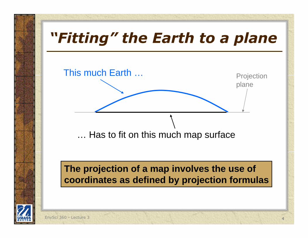
“Fitting” the Earth to a plane
This much Earth …
… Has to fit on this much map surface
Projectionplane
The projection of a map involves the use ofcoordinates as defined by projection formulas

5EnvSci 360 - Lecture 3 5
A quick look at projections
https://www.youtube.com/watch?v=kIID5FDi2JQ
Also see: http://thetruesize.com

6EnvSci 360 - Lecture 3 6
Earth Facts
Equatorial Diameter: 7,926.59 mi.
Polar Diameter: 7,900.01 mi.
Equatorial Circumference: 24,902.13 mi.
Polar Circumference: 24,818.64 mi.
Earth is considered an oblate spheroid -- a solid formed when an ellipse is rotated about its axis

7EnvSci 360 - Lecture 3 7
The Geoid
But even if we assume the earth is an oblate spheroid, we actually model it as a “geoid” –the representation of the earth if the planet were covered only by the oceans.
– Mean Sea Level (MSL) + Gravitational Pull
8EnvSci 360 - Lecture 3 8
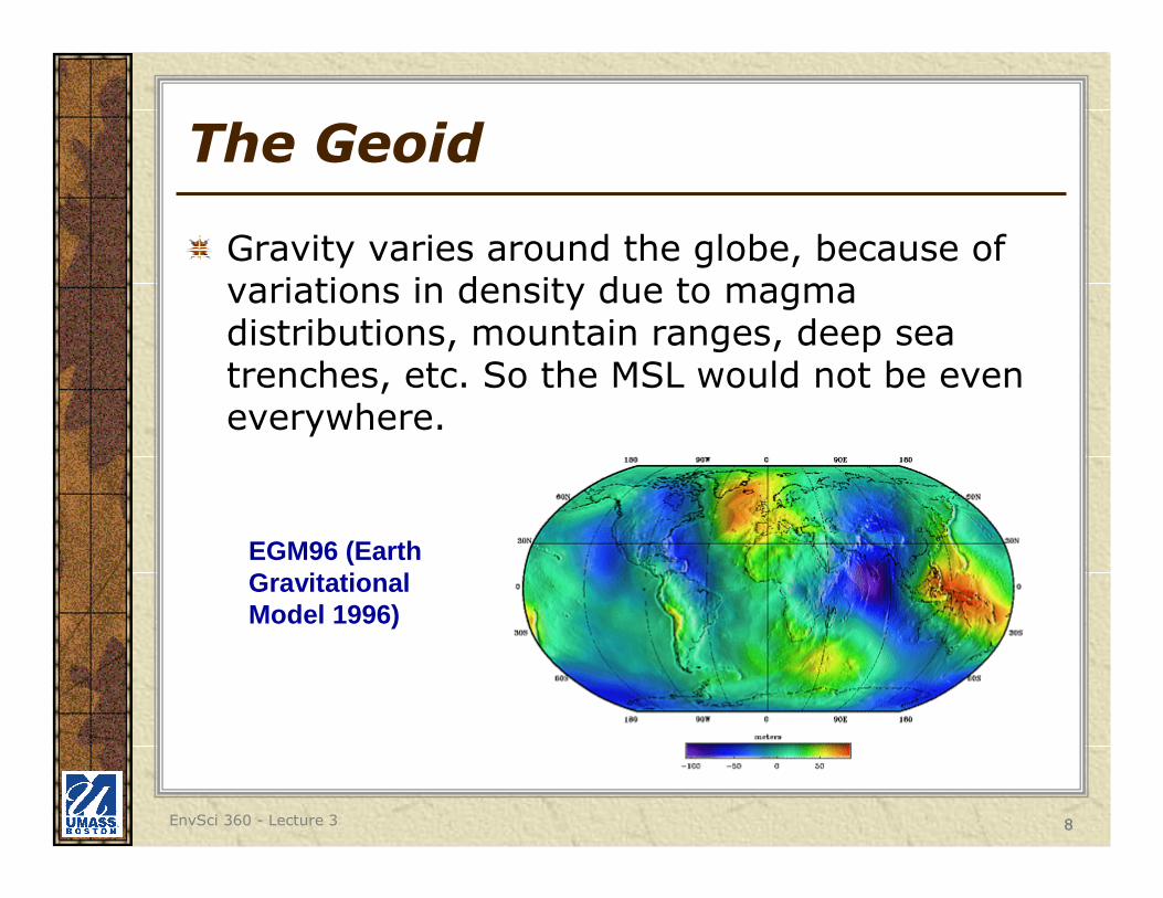
The Geoid
Gravity varies around the globe, because of variations in density due to magma distributions, mountain ranges, deep sea trenches, etc. So the MSL would not be even everywhere.
EGM96 (Earth Gravitational Model 1996)
9EnvSci 360 - Lecture 3 9
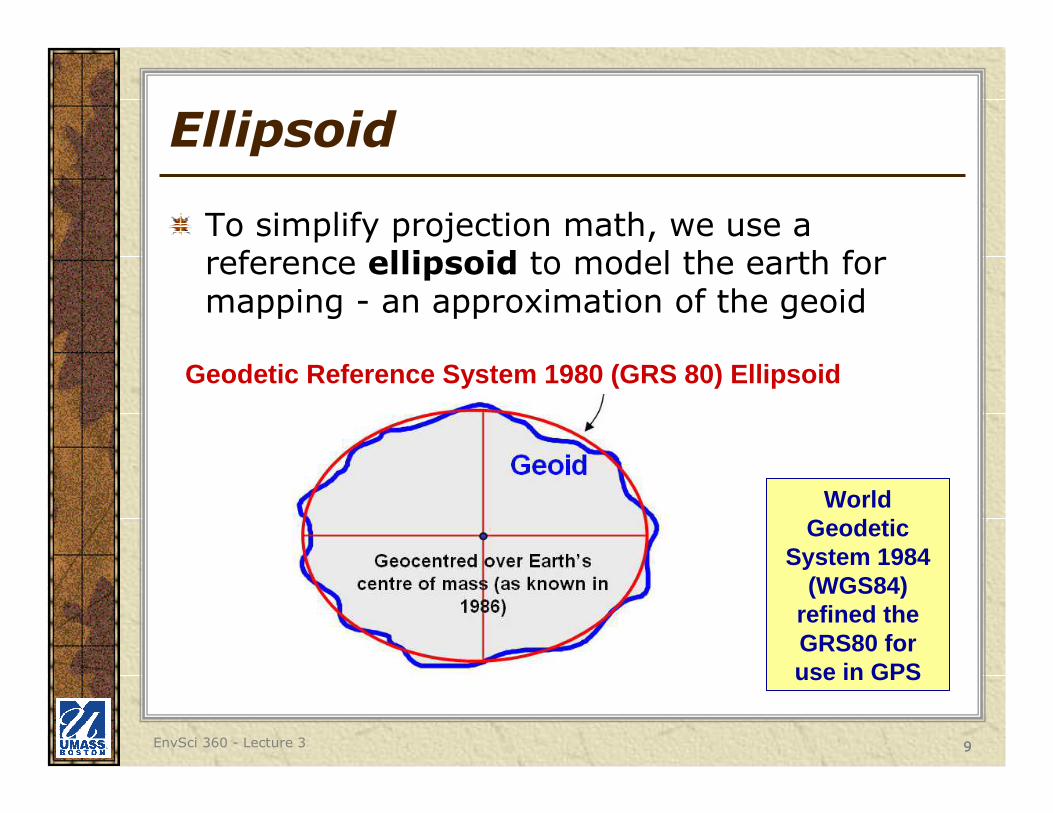
Ellipsoid
To simplify projection math, we use a reference ellipsoid to model the earth for mapping - an approximation of the geoid
World Geodetic
System 1984 (WGS84)
refined the GRS80 for use in GPS
Geodetic Reference System 1980 (GRS 80) Ellipsoid

10EnvSci 360 - Lecture 3 10
Ellipsoid
A theoretical surface of the Earth which approximates mean sea level
Has 2 axes:
– Major
• the axis withthe greatestradius
– Minor
• the axis withthe least radius
b
a

11EnvSci 360 - Lecture 3 11
Ellipsoid
Widely used ellipsoids adopted in the U.S.:
– 1) Clark ellipsoid of 1866 (datum – NAD27 (North American
Datum of 1927))
– 2) Geodetic Reference System (GRS80) (datum – NAD83 (North American Datum of 1983))
• Original basis for WGS84, which now uses the EGM96 (Earth Gravitational Model 1996) geoid, last revised in 2004
294.97869826,356,583.8 m6,378,206.4 mClark 1866
Ellipsoid reference Semi-major axis a Semi-minor axis b Inverse flattening (1/f)
GRS 80 6,378,137.0 m ≈ 6,356,752.314 140 m 298.257 222 101
WGS 84 6,378,137.0 m ≈ 6,356,752.314 245 m 298.257 223 563

12EnvSci 360 - Lecture 3 12
Sphere, Geoid, Ellipsoid
13EnvSci 360 - Lecture 3 13
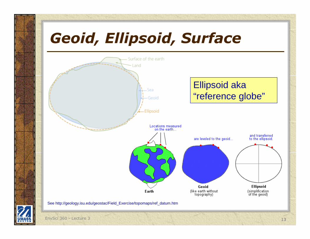
Geoid, Ellipsoid, Surface
Ellipsoid aka “reference globe”
See http://geology.isu.edu/geostac/Field_Exercise/topomaps/ref_datum.htm
14EnvSci 360 - Lecture 3 14
Map Projection
The systematic mathematical transformation of the three-dimensional curved surface of the Earth to the two-dimensional flat surface of a map.
– Basically, it is how you “show” the curved 3-D Earth on a flat map.
Attempt to accurately depict the following characteristics:
1. Direction
2. Distance
3. Area
4. Shape
* No Map Projection can accuracy depict all four characteristics at once.
Every map projection will contain some distortion.
15EnvSci 360 - Lecture 3 15
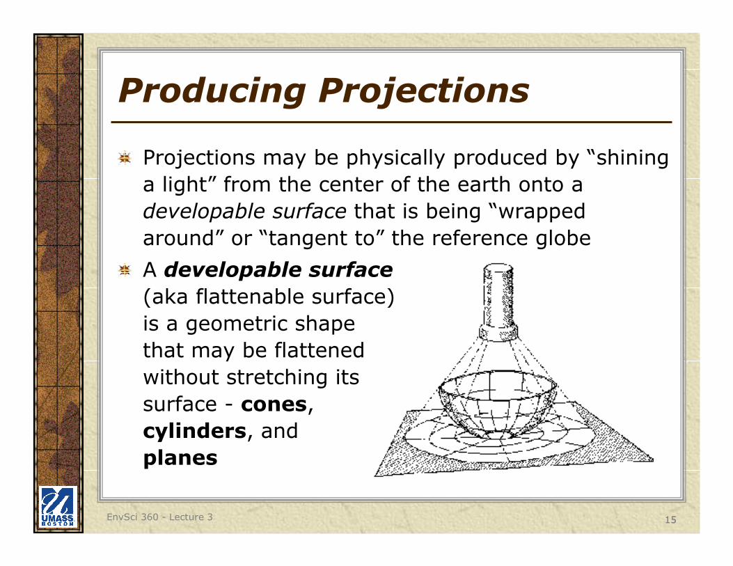
Producing Projections
Projections may be physically produced by “shining
a light” from the center of the earth onto a
developable surface that is being “wrapped
around” or “tangent to” the reference globe
A developable surface
(aka flattenable surface)
is a geometric shape
that may be flattened
without stretching its
surface - cones,
cylinders, and
planes

16EnvSci 360 - Lecture 3 16
Producing Projections
Flat mapsDevelopable surfaces

17EnvSci 360 - Lecture 3 17
Producing Projections
First step is to create
one or more points of
contact between the
developable surface
and the reference
globe - these are
called points of
tangency
A tangent projection
is one where the
developable surface
touches in one location
18EnvSci 360 - Lecture 3 18
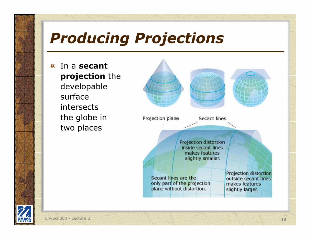
Producing Projections
In a secant
projection the
developable
surface
intersects
the globe in
two places
19EnvSci 360 - Lecture 3 19
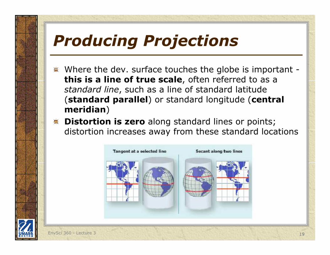
Producing Projections
Where the dev. surface touches the globe is important -this is a line of true scale, often referred to as a standard line, such as a line of standard latitude (standard parallel) or standard longitude (central meridian)
Distortion is zero along standard lines or points; distortion increases away from these standard locations

20EnvSci 360 - Lecture 3 20
Cylindrical Projection – Conceptual View
(Tangent)
21EnvSci 360 - Lecture 3 21
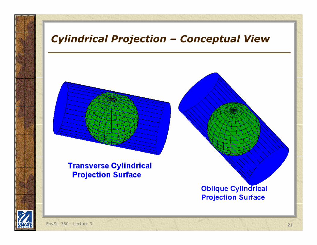
Cylindrical Projection – Conceptual View

22EnvSci 360 - Lecture 3 22
Cylindrical Projection - Example
Miller's Cylindrical Projection

23EnvSci 360 - Lecture 3 23
Cylindrical Projection - Example
Cassini's projection is a transverse aspect, here with central meridians at 70°E and 110°W

24EnvSci 360 - Lecture 3 24
Conic Projection – Conceptual View
Secant Conic Projection

25EnvSci 360 - Lecture 3 25
Conic Projection - Example
How flat maps look when the cone is “unfurled”

26EnvSci 360 - Lecture 3 26
Planar (Azimuthal) Projection– Conceptual View
Secant Planar Projection
27EnvSci 360 - Lecture 3 27
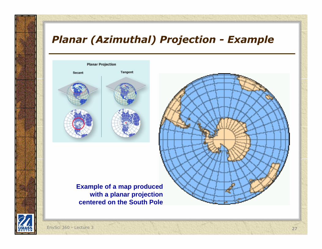
Planar (Azimuthal) Projection - Example
Example of a map produced with a planar projection
centered on the South Pole

28EnvSci 360 - Lecture 3 28
Orthographic Projection
Perspective view that depicts a hemisphere of the globe as it appears from outer space
29EnvSci 360 - Lecture 3 29
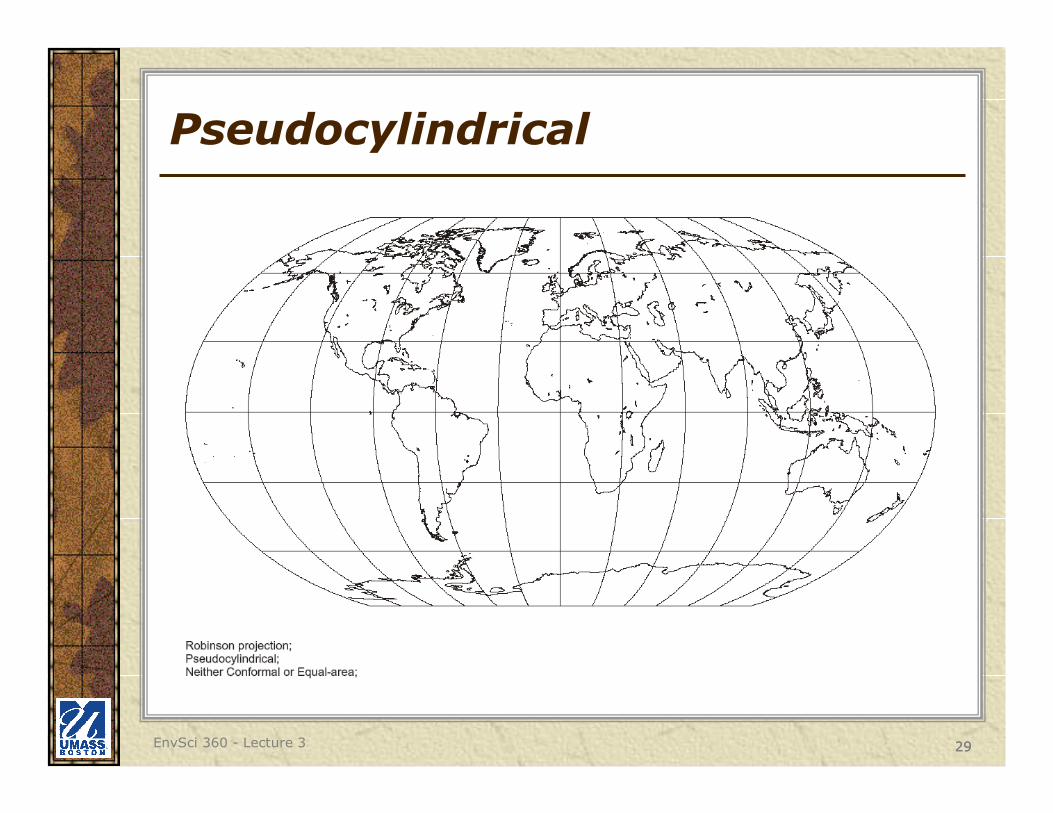
Pseudocylindrical
30EnvSci 360 - Lecture 3 30
Other Ways of Categorizing Projections
Along with using Cylinders, Cones and Planes to categorize projections, we can also categorize them based on their inherent distortions

31EnvSci 360 - Lecture 3 31
Distortion With Projections
Shape (Conformality)
Distance
Direction
Area
Different map projections preserve some of these properties or attempt to reduce the distortion of some or all of these properties, but NO map projection preserves all these properties.
Scale also can be distorted, or differ, throughout a single map

32EnvSci 360 - Lecture 3 32
Conformal Projections
Conformal projections preserve local shape– At every point the scale is the same in every direction
– Graticule lines intersect at 90-degree angles
– All angles between intersections of arcs are maintained
– Shapes of very small areas and angles with very short sides are preserved.
– Size of many areas are distorted

33EnvSci 360 - Lecture 3 33
Equal-area Projections
Equal-area projections preserve the relative area of displayed features– Every part on the map, as well as the whole, has the same
area as the corresponding part on the Earth, at the same reduced scale
– Shape, angles, scale may be distorted
– Graticule lines may not meet at 90-degree angles
Albers Equal Area

34EnvSci 360 - Lecture 3 34
Equal-area Projections

35EnvSci 360 - Lecture 3 35
Equal-area Projections
36EnvSci 360 - Lecture 3 36
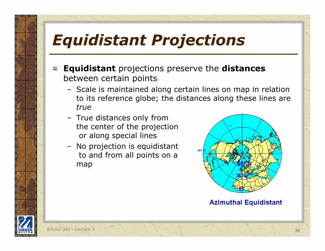
Equidistant Projections
Equidistant projections preserve the distancesbetween certain points
– Scale is maintained along certain lines on map in relation to its reference globe; the distances along these lines are true
– True distances only from the center of the projectionor along special lines
– No projection is equidistantto and from all points on a
map
37EnvSci 360 - Lecture 3 37
True-direction Projections
True-direction or azimuthal projections preserve the direction of specified points on a great circle
– The shortest route between two points on a curved surface such as the earth is along the spherical equivalent of a straight line on a flat surface - called the great circle
– Great circle arcs are rectified, or shown as straight lines
– Azimuths (angles from a point on a line to another point) are portrayed correctly in all directions
See http://www.colorado.edu/geography/gcraft/notes/mapproj/mapproj.html for a good list and examples of different projections

38
Distortion With Projections
Both of these maps are based on equal-area projections, but distances between the same two locations on the globe are not equal
39EnvSci 360 - Lecture 3 39
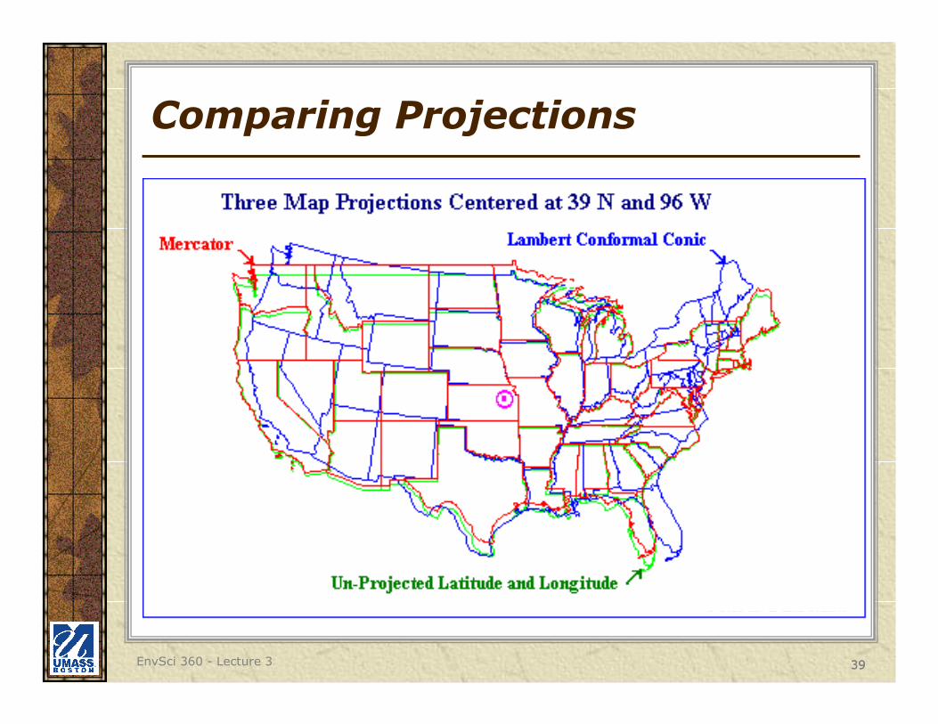
Comparing Projections

40EnvSci 360 - Lecture 3 40
Comparing Projections

41EnvSci 360 - Lecture 3 41
Which Projection to Use?
Computers do the transformations, but the cartographer’s primary task is to choose the proper projection
Ask -
– what is the purpose of the map?
– Will the projection influence the map’s effectiveness?
42EnvSci 360 - Lecture 3 42
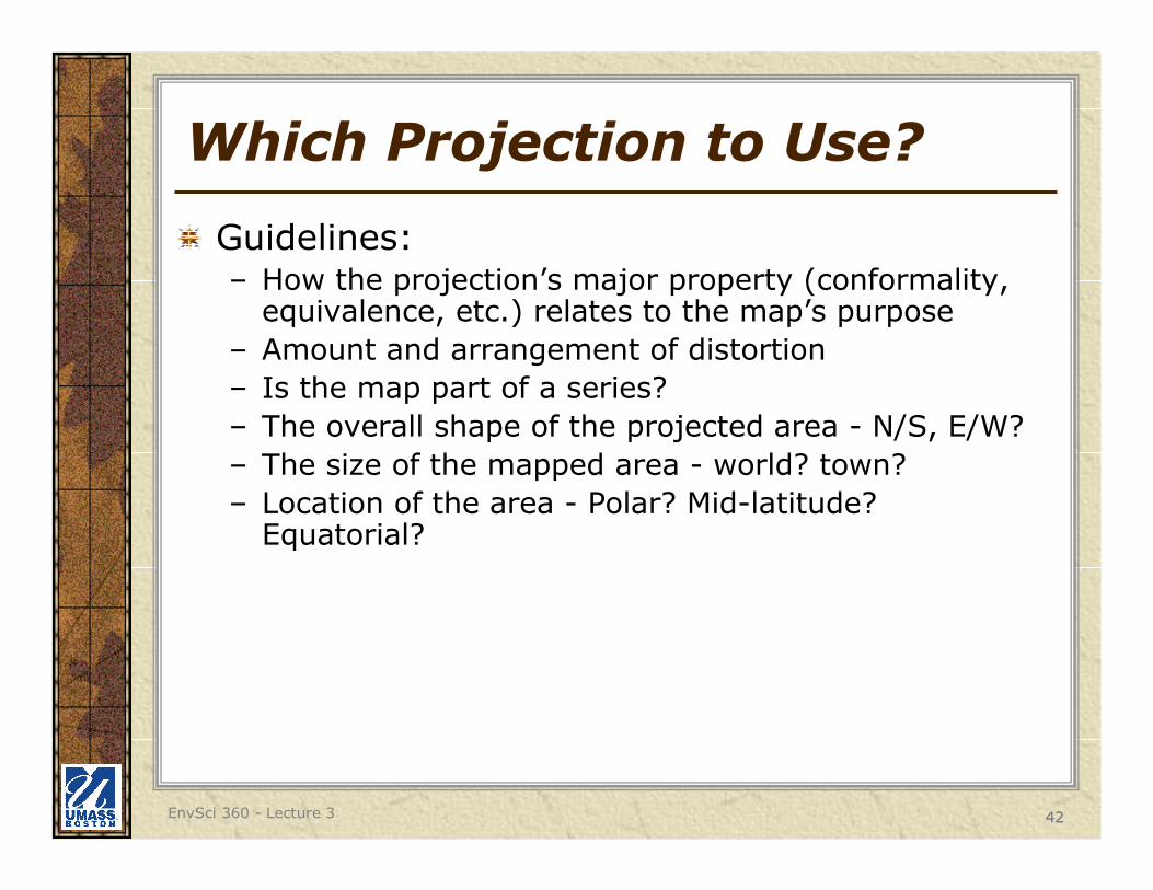
Which Projection to Use?
Guidelines:– How the projection’s major property (conformality,
equivalence, etc.) relates to the map’s purpose
– Amount and arrangement of distortion
– Is the map part of a series?
– The overall shape of the projected area - N/S, E/W?
– The size of the mapped area - world? town?
– Location of the area - Polar? Mid-latitude? Equatorial?

43EnvSci 360 - Lecture 3 43
Which Projection to Use?
Equal-area for thematic or distribution maps (statistical mapping)
True-direction and/or equidistant for navigational
Conformal for presentation maps

44EnvSci 360 - Lecture 3 44
“Compromise” Projections
Neither true shapes, true directions, true areas, nor true distances, but a compromise among these properties
Attempts to minimize the distortions inherent in some of these properties when others are made to be true

45
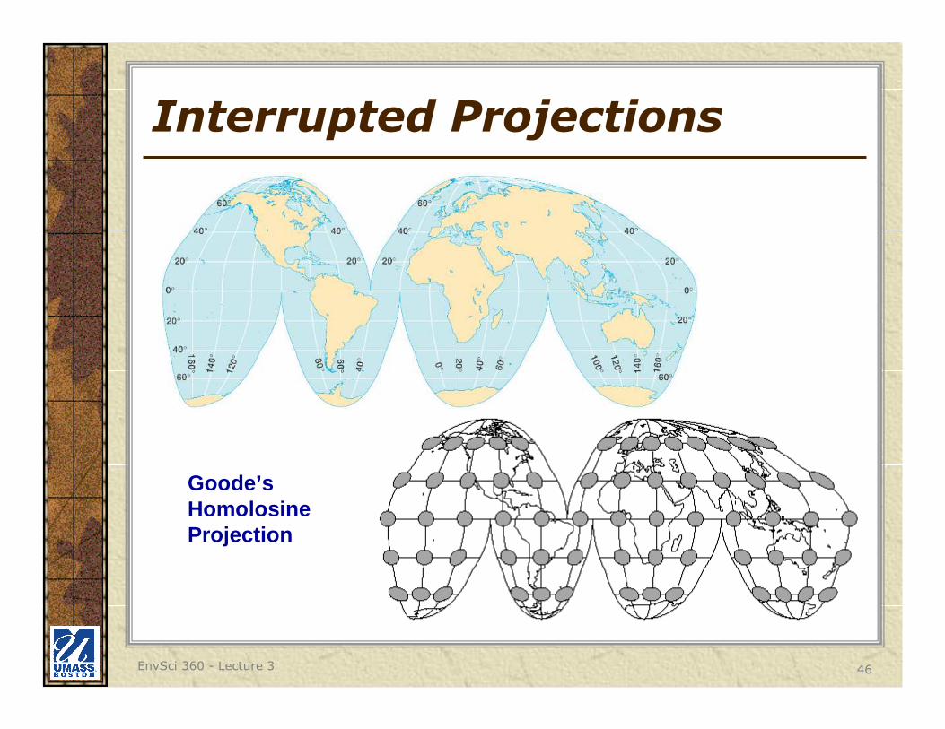
Interrupted Projections
A compromise projection, "cutting" the earth’s surface along arbitrarily chosen lines and projecting each section separately, which results in less stretching.
Interrupted sinusoidal map
EnvSci 360 - Lecture 3
46
Interrupted Projections
Goode’s HomolosineProjection
EnvSci 360 - Lecture 3
47
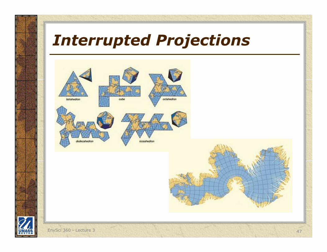
Interrupted Projections
EnvSci 360 - Lecture 3

48
Web Mercator
Standard for web-based mapping
Used by Microsoft Bing Maps, Google Maps, and ESRI ArcGIS Online
See http://www.esri.com/events/seminars/bettermaps/mate rials/~/media/files/pdfs/events/seminars/bettermaps /materials/pdfs/we
bmercatorsmnrbrochure.pdfhttp://www.hydrometronics.com/downloads/Web%20Merca tor%20-%20Non-Conformal,%20Non-
Mercator%20%28notes%29.pdfhttp://gis.stackexchange.com/questions/12646/why-ha s-web-mercator-auxiliary-sphere-become-the-web-map- standard
http://msdn.microsoft.com/en-us/library/bb259689.as px
EnvSci 360 - Lecture 3

49EnvSci 360 - Lecture 3 49
Horizontal Control
In order for a projection to be used as a map, a datum must be declared.
Datum - a set of quantities to serve as a referent (or point of reference)
– have an origin
– measurement based on a datum must be repeatable

50EnvSci 360 - Lecture 3 50
Horizontal Control
Datum - sets of parameters defining a coordinate system, and a set of control points whose geometric relationships are known, either through measurement or calculations.
Simply put, a datum is the mathematical model of the Earth we use to calculate the coordinates on any map, chart, or survey system. All coordinates reference some particular set of numbers (datum) for the size and shape of the Earth.

51EnvSci 360 - Lecture 3 51
Horizontal Control
In North America: two geodetic datum are commonly used for displaying spatial data:
1. North American Datum of 1983 (NAD83) - based on 250,000 satellite measurements and GRS-80 Ellipsoid & more accurate; has been refined a few times since (e.g. NAD 83( CORS 96) and NAD 83(NSRS2007))
- Units: Meters
2. North American Datum of 1927 (NAD27) - based on 25,000 ground surveys and Clarke 1866 Ellipsoid & less accurate.
- Units: Feet

52EnvSci 360 - Lecture 3 52
NAD27 vs. NAD83
Shift is shown on USGS Quad maps and will result in map projections from one datum to another.
NAD83NAD27

53EnvSci 360 - Lecture 3 53
Geo-Referencing Systems
As mentioned previously, all data displayed and analyzed in a GIS have a spatial component (geographic reference – a reference to a location on the earth)
In order to display and analyze multiple layers of spatial data for the same geographic area in a GIS, the multiple data layers must be associated with a geo-referencing system (or coordinate system)
A coordinate system is closely related to a datum (has an origin)

54EnvSci 360 - Lecture 3 54
Geo-Referencing Systems
Locate points precisely
2-D (X,Y) or 3-D (X,Y,Z)
Two major types used today–Geographical (latitude/longitude) -
curved Earth
–Rectangular or Plane (aka Projected)- based on a grid with an origin (i.e. Cartesian coords) - flat map

55EnvSci 360 - Lecture 3 55
Geo-Referencing Systems
Geographic Grid – a.k.a Latitude & Longitude
– Continuous, 3-D
– is geo-referenced... but not suitable for 2D mapping (not planar)

56EnvSci 360 - Lecture 3 56
Geographical Coordinates

57EnvSci 360 - Lecture 3 57
Geographic Coordinates
Latitude (y) - north-south distance from the equator - the “origin”. Also called parallels.
Longitude (x) - east-west angular distance from a prime meridian - the “origin”. Also called meridians.
Not a map projection - a set of spherical coordinates used to reference positions on the curved surface of the Earth for use in map projections.
Basis for projected coordinate systems

58EnvSci 360 - Lecture 3 58
Latitude
A function of the angle between the horizon and the North Star
Range: 0 – 90 degrees
Origin: The Equator
Direction: North and South of the origin

59EnvSci 360 - Lecture 3 59
Longitude
Comprises meridians (half circles)
Range: 0 – 180 degrees
Origin: The Prime Meridian
Direction: East andWest of the origin
60EnvSci 360 - Lecture 3 60
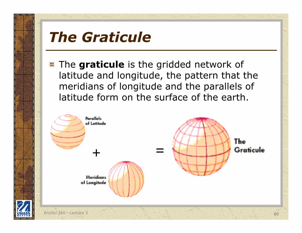
The Graticule
The graticule is the gridded network of latitude and longitude, the pattern that the meridians of longitude and the parallels of latitude form on the surface of the earth.
+ =

61EnvSci 360 - Lecture 3 61
Properties of the Graticule
Great Circle - circle created by a plane that intersects 2 points and the center of the Earth (i.e. meridians or the equator)
Small Circle - any circle created by an intersecting plane that doesn’t cut through the center of the Earth (any parallel other than the equator)

6262
Properties of the Graticule
Different ways of creating great circles
See http://www.csulb.edu/~rodrigue/geog140/lectures/geographicgrid.html

63EnvSci 360 - Lecture 3 63
Measuring Distance
The shortest distance between 2 points on a curved surface is the great circle arc above the true “connector line”
A B
True connector line (underground)
Great Circle arc

64EnvSci 360 - Lecture 3 64
Direction on the Graticule
Bearing, course, heading, flightline, azimuth are other terms for direction
True azimuth - cross meridians at different angles
Constant azimuth (rhumb line) -cross meridians at the same angle
Direction is important to commercial flight maps

65EnvSci 360 - Lecture 3 65
Types of Latitude and Longitude
Authalic - measured form the center of the earth; measured on a sphere
40°
0°
0°Prime meridian
Equator
Authaliclatitude
Longitude

66EnvSci 360 - Lecture 3 66
Types of Latitude and Longitude
Geodetic - measured perpendicular to the surface; measured on an ellipsoid

67EnvSci 360 - Lecture 3 67
Latitude/Longitude Coordinates
1 - Degrees, minutes, seconds (DMS)
dddmmssDor ddd mm'ss" D
where ddd = 1-3 digits for degrees, mm = 2 digits for minutes, ss = 2 digits for seconds and D = N,S,E, or W. The seconds and special characters (spaces, apostrophes, quotes) are all optional in this format. This leads to quite a large number of possible valid formats. Ex. 42° 37’ 30’’ N 71° 00’ 50’’ W
2 -Decimal degrees (DD)
ddd.ffffDwhere ddd = 0-3 digits, ffff = 0-10 digits and D = N,S,E, or W. This format represents a decimal number of degrees. If the number of degrees is a whole number, the decimal point is optional. Ex. 42.625° N 71.014° W

68EnvSci 360 - Lecture 3 68
DMS to DD
42° 37’ 30’’ N = 42.625° N
30/60 = .5 -> 37.537.5/60 = .625
Conversion of DMS and DD
360 degrees in a circle
60 minutes to a degree
60 seconds to a minute, so …
DD to DMS
42.625° N = 42° 37’ 30’’ N
.625 x 60 = 37.5
.5 x 60 = 30

69EnvSci 360 - Lecture 3 69
Latitude/Longitude Coordinates
Remember - positive or negative??
Equator
Prime meridian
Negative
Positive
Negative Positive

70EnvSci 360 - Lecture 3 70
Geo-Referencing Systems
Cartesian– A planar coordinate system (X and Y axis)
– Geo-referenced only when related to the graticule and real-world units are used
71EnvSci 360 - Lecture 3 71
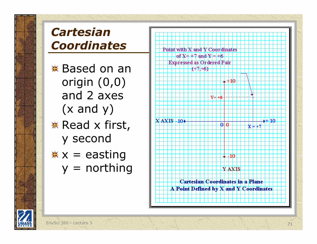
Cartesian Coordinates
Based on an origin (0,0)and 2 axes(x and y)
Read x first,y second
x = eastingy = northing

72EnvSci 360 - Lecture 3 72
Coordinate Systems
In GIS, the two most common rectangular coordinate systems used for spatial data in the U.S. are:
1. Universal Transverse Mercator (UTM)
2. State Plane Coordinate System (SPC)
Note: Underlying these planar coordinate systems is the latitude/longitude graticule

73EnvSci 360 - Lecture 3 73
UTM Coordinate System
Universal Transverse Mercator
World divided into north/south columns, each 6°longitude wide
Origin is central meridian and equator
Most widely used coordinate system in the world
Primarily used for land masses extending in a north-south direction
Modified for use on USGS Quad maps– central meridian of each zone
given false easting of 500000
– equator given false northing of 0

74EnvSci 360 - Lecture 3 74
UTM Coordinate System

75EnvSci 360 - Lecture 3 75
UTM Coordinate System
60 zones (begin at 180W)
Each zone:– Comprises 6 Degrees of
Longitude
– Has its own origin
In the Northern Hemisphere:– origin is at the Equator and
500,000 (m) west of the Central Meridian

76EnvSci 360 - Lecture 3 76
UTM Zones in USA

77EnvSci 360 - Lecture 3 77
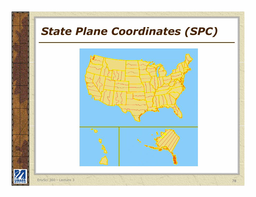
State Plane Coordinates (SPC)
Rectangular grid, based on X, Y and false eastings and northings
Developed in order to provide local reference systems that were tied to a national datum (i.e. NAD83).
A coordinate system, not a projection
Some states may have many zones
– Mass. has Mainland and Island
78EnvSci 360 - Lecture 3 78
State Plane Coordinates (SPC)

79EnvSci 360 - Lecture 3 79
False Easting and Northing
Arbitrary large values given to x and y axes so that all values in the grid will be positive
The origin (0,0) moves to the southwest

80EnvSci 360 - Lecture 3 80
Massachusetts State Plane
Full domain of MASPC, with false easting and northing
UMB Science Building: X: 238,100m Y: 895,960m

81EnvSci 360 - Lecture 3 81
Massachusetts State Plane
MAINLAND ZONE(FIPSZONE 2001)
ISLAND ZONE(FIPSZONE 2002)

82EnvSci 360 - Lecture 3 82
Massachusetts State Plane
Zoomed in, shift is evident between zones
MAINLAND ZONEISLAND ZONE
The coordinate system used for this map image is Mainland Zone

83EnvSci 360 - Lecture 3 83
Geographic vs. State Plane
MAINLAND ZONE SPC USGS QUADS (Geographic)
The coordinate system used for this map image is SPC Mainland Zone

84EnvSci 360 - Lecture 3 84
3 Grids in Mass.
State Plane UTM Lat/Long
85EnvSci 360 - Lecture 3 85
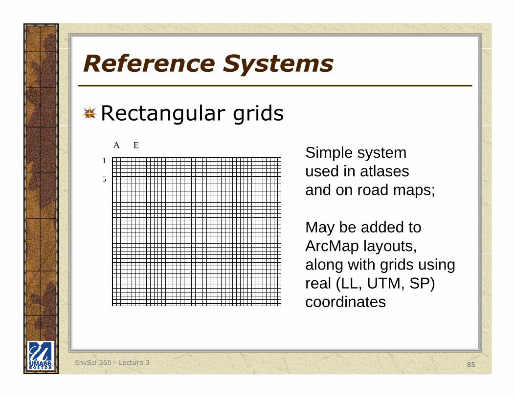
Reference Systems
Rectangular grids
A E
1
5
Simple systemused in atlasesand on road maps;
May be added to ArcMap layouts, along with grids using real (LL, UTM, SP) coordinates
86EnvSci 360 - Lecture 3 86
Coordinate System Codes
FIPSZONEs for state plane
EPSG codes are commonly used to identify a coordinate system
– European Petroleum Survey Group
– http://www.epsg.org
– http://spatialreference.org/ref/epsg/
Also WKIDs (well-known IDs) for GCS – https://developers.arcgis.com/javascript/jshelp/gcs.
html.NAD83 Mass. State Plane Mainland:FIPSZONE = 2001EPSG = 26986

87EnvSci 360 - Lecture 3 87
Projections in ArcGIS
All datasets have some coordinate system (aka “spatial reference”) although it may not be known (defined)Data in different coordinate systems are projected, or converted from one to another, on the fly, ONLY IF spatial references are properly defined.– Use the DEFINE PROJECTION tool if spatial reference is
unknown or incorrect– If datasets with different spatial
references are not properly defined, they will not align properly on the map.
The PROJECT tool will create a new dataset with a converted (transformed) coordinate system.
DEFINE PROJECTION
PROJECT (vector)
PROJECT (raster)

88EnvSci 360 - Lecture 3 88
Vertical Control
Measurements of elevation that may serve as a reference to topographic mapping (i.e. of contour lines or digital elevation models).
2 networks have been devised:
– National Geodetic Vertical Datum of 1929
– North American Vertical Datum of 1988
GPS now determines elevations based on the WGS 84 Ellipsoid latest revision
89EnvSci 360 - Lecture 3 89
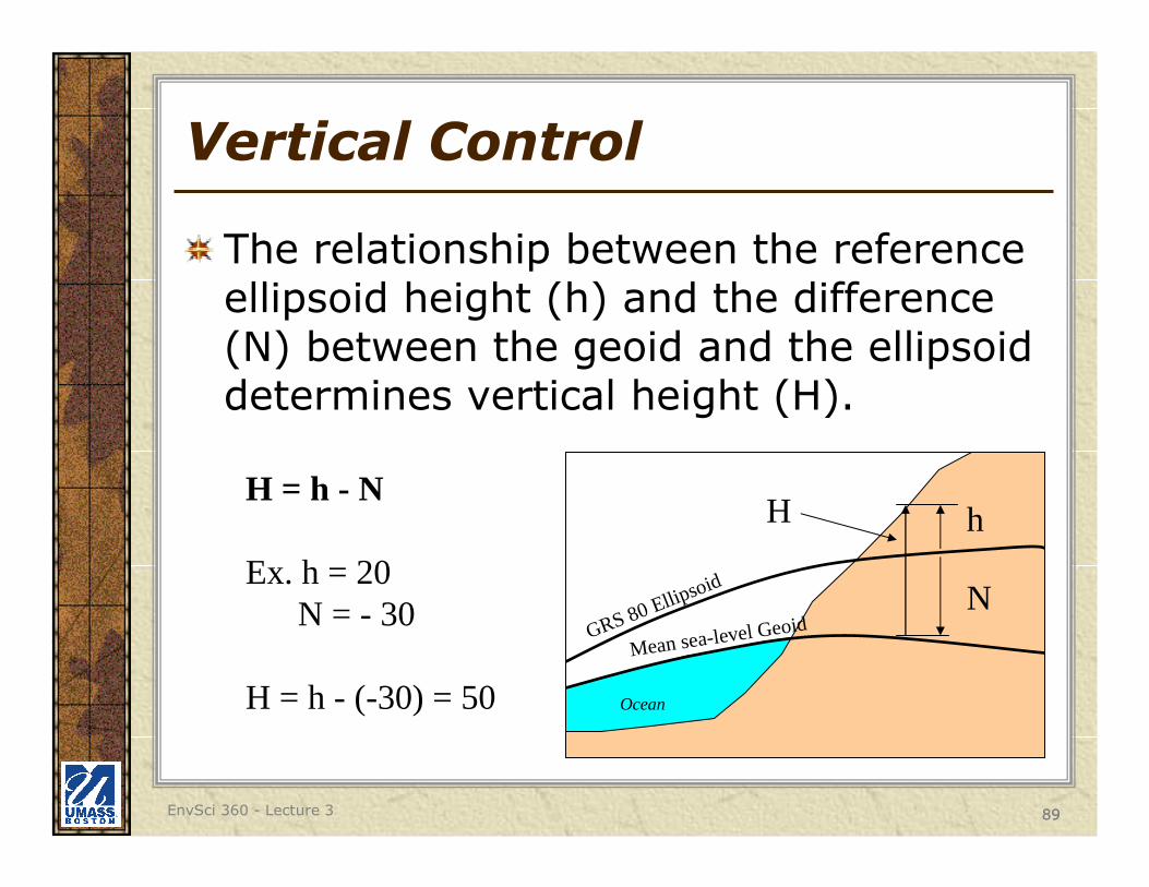
Vertical Control
The relationship between the reference ellipsoid height (h) and the difference (N) between the geoid and the ellipsoid determines vertical height (H).
GRS 80 Ellipsoid
Mean sea-level Geoid
Ocean
H = h - N
Ex. h = 20N = - 30
H = h - (-30) = 50
N
hH