geohorizon authors restorations of faulted...
TRANSCRIPT

GEOHORIZON
Restorations of faulted domesMohammedM. Al-Fahmi, Andreas Plesch,John H. Shaw, and John C. Cole
ABSTRACT
We illustrate recently developed techniques of three-dimensional(3-D) geomechanical structural restoration applied to resolve thekinematics of deformation in the sedimentary cover above mobilesalt. Our study area is one of the hydrocarbon-bearing domes ineastern Arabia. We used 3-D seismic reflection and well data tobuild a 3-D structural geomodel for the well-imaged part ofthe sedimentary cover. The geomodel includes faults and a3.2-km(2-mi) thick section of Permian to Cenozoic sediments and isrestored from the Jurassic to the present day. The development ofthe structures is characterized by stages of normal faulting in theJurassic and Cretaceous and a subsequent stage of low-amplitudefolding in the Late Cretaceous. We interpret that the develop-ment of the structures in the sediment cover is caused by themovement of a deep, nonpiercing salt pillow. The structures grewunder the control of gradually changing deforming mechanisms,from dominantly faulting to folding. The transition from normalfaulting to domal folding is indicative of a reactive salt diapir.These restoration results improve our understanding about thekinematic history of the structures developed within the Jurassicand Cretaceous sedimentary section, which contains most of thehydrocarbon resources in Arabia. Moreover, they illustrate thepotential of geomechanical restoration methods to investigatestructures above mobile salt systems.
INTRODUCTION
Characterization of subsurface structures requires the in-tegration of data and interpretations in a three-dimensional(3-D) modeling framework, with consideration of how thestructure developed over geologic time. Such a geomodeling
AUTHORS
Mohammed M. Al-Fahmi ~ Departmentof Earth Sciences, University of Oxford, SouthParks Road, Oxford OX1 3AN, UnitedKingdom; [email protected]
MohammedM.Al-Fahmi is currentlypursuingaPh.D. in earth sciences at the University ofOxford, United Kingdom. He worked as ageologist for Saudi Aramco, immediately afterhis graduation in 2004 with a B.S. degree inearth sciences from King Abdulaziz University.His work experience includes geomodelingof rock fractures, structural geology, andhydrocarbon reservoir characterization andsimulation. He obtained an M.S. degreein geosciences from the University ofMassachusetts Amherst in 2012. He was also avisiting scholar with the Structural GeologyGroup of Harvard University in 2012.
Andreas Plesch ~ Department of Earthand Planetary Sciences, Harvard University,20 Oxford Street, Cambridge, Massachusetts02138; [email protected]
Andreas Plesch is a research associate in theStructural Geology and Earth Resources Groupin the Earth and Planetary Science Departmentat Harvard University. He received an M.S.degree in geology from State University of NewYork,Albany(1994),andhisPh.D. fromtheFreeUniversityBerlin,Germany(1999).His researchinterests involve three-dimensional modelingand analysis of contractional structures on thereservoir to mountain belt scale using a varietyofmethodswith a focus on quantitative aspectsand interpretation of seismic reflection data. Hehas been able towork on structuresworldwide,commonly in cooperation with industrypartners.
John H. Shaw ~ Department of Earth andPlanetary Sciences, Harvard University, 20Oxford Street, Cambridge, Massachusetts02138; [email protected]
John H. Shaw is the Harry C. Dudley Professorof Structural and Economic Geology andChair of the Earth and Planetary SciencesDepartment at Harvard University. He leads anactive research program in structural geologyand geophysics, with emphasis on petroleumexploration and production methods. Hereceived a Ph.D. from Princeton University in
Copyright ©2016. The American Association of Petroleum Geologists. All rights reserved. Green OpenAccess. This paper is published under the terms of the CC-BY license.
Manuscript received November 18, 2014; provisional acceptance February 5, 2015; revised manuscriptreceived June 12, 2015; final acceptance August 17, 2015.DOI:10.1306/08171514211
AAPG Bulletin, v. 100, no. 2 (February 2016), pp. 151–163 151

approach improves knowledge on where, when, and howstructures developed and subsequently guides the tectonic in-terpretation. The validity of geomodels is commonly subject tointerpreter judgments (e.g., Bond et al., 2007) but can be verifiedand enhanced by certain objective methods including structuralrestoration. Structural restoration techniques have been used fordecades to validate seismic interpretations and derive a generalframework for stratal geometries (e.g., Chamberlin, 1910;Dahlstrom, 1969; Gibbs, 1983; Erslev, 1991; Gratier andGuillier,1993; Shaw et al., 1994; Williams et al., 1997; Allmendinger,1998; Rouby et al., 2000; Griffiths et al., 2002; Maerten andMaerten, 2006; Moretti et al., 2006). Various restoration tech-niques have proven valuable in areas with large uncertainties ingeomodeling, which may result from limited data and/or fromspatially complex structures. Furthermore, the techniques areregularly applied to reduce the uncertainties in the modeling ofthe subsurface structures targeted for exploration and develop-ment of hydrocarbon resources.
Traditional restoration techniques, however, retain the majorlimitations of Dahlstrom’s model, which applies geometric andkinematic rules in two-dimensional domains. Dahlstrom (1969)assumed plane strain to describe structures and rationalized thatvalid geologic cross sections must preserve cross-sectional areasand line lengths of folded strata through restoration. The as-sumption of conservation of bed line lengths presumed the ac-commodation of off-fault strain by bed-parallel, flexural slip. Thecurrent techniques that use Dahlstrom’s assumptions havewidespread application in contractional and extensional geologicsettings, but their application is limited for inherently 3-Dstructures, including those that involve salt (e.g., Rowan andRatliff, 2012).
In this study, we seek to overcome the limitations of tradi-tional restoration methods through the application of a new 3-Dgeomechanical restoration technique (e.g., de Santi et al., 2003;Mueller et al., 2005; Muron et al., 2005; Guzofski et al., 2009;Durand-Riard et al., 2010) to a structure that is driven by mobilesalt. This method has proven effective at sequentially restoringcontractional, extensional, and strike-slip structures (e.g.,Maertenand Maerten, 2006; Moretti et al., 2006; Plesch et al., 2007;Durand-Riard et al., 2013; Li et al., 2013). However, restorationof salt-related structures is difficult because of the inherent limitsof the simple constitutive laws and continuum (finite-element)based methods implemented in these restoration tools. Thus, ourapproach to the problems of salt-related structures is to focus ondeciphering components of folding and faulting within strataabove the salt. We make no assumption about salt geometry,budget, and halokinesis. We test this approach on a faulted saltdome, where faults grew and branched to cut through roof strata,producing complex geologic structures that trap hydrocarbon
structural geology and applied geophysics andwas employed as a senior research geoscientistat Texaco’s Exploration and ProductionTechnology Department in Houston, Texas.Shaw’s research interests include complex trapand reservoir characterization in fold-and-thrust belts and deepwater passivemargins. Heheads the Structural Geology and EarthResources Program at Harvard, anindustry–academic consortium that supportsstudent research in petroleum systems.
John C. Cole ~ Sasol Canada, Suite 1600,215-9th Avenue SW, Calgary, Alberta,Canada T2P1K3; [email protected]
John C. Cole is currently lead geoscientist atSasol Canada. John has over 30 years ofexperience in exploration and developmentwith several major oil and gas companiesincludingTexaco,BP,SaudiAramco, andRepsolUSA. He obtained an M.Sc. degree fromImperial College, United Kingdom, in 1980. Hiseducational background is in structural geologyand rock mechanics, and over the years he hasdeveloped expertise in geocellular modeling,carbonate reservoir characterization, andfracture characterization and modeling.
ACKNOWLEDGMENTS
We thank Saudi Aramco for funding thisproject and for giving us the technical reviewand permission to publish the results. Wehighly appreciate the contributions made bynumerous members from the managerialand technical staff of the ReservoirCharacterization Department. The authorsperformed the project at Harvard Universityand appreciate the support of theDepartment of Earth and Planetary Sciences.
152 Geohorizon

resources. Our goal is to assess if the restorationtechniques can recover viable deformation kine-matics, resolve the relative contributions of foldingand faulting in the growth of the structure, and inferindirectly the history of salt motion.
GEOLOGIC BACKGROUND
The study area is an onshore, multi-reservoir hy-drocarbon field, located on the western periphery ofthe north basin of the Persian Gulf (Figure 1). Theanticlinal structure is one ofmany domes in the regionattributed to the deeply buried salt diapirism beneaththe eastern Phanerozoic sequence of the Arabianplate (e.g., Powers et al., 1966; Edgell, 1991). Buriedsalt domes are interpreted on the basis of the ge-ometry of the cover sediments aligned with strongnegative gravity anomalies (e.g., Edgell, 1991). Thesalt is interpreted to be part of the infra-CambrianHormuz salt, which is exposed within the Zagros andMakran mountain belts of Iran (e.g., Talbot, 1998).
Approximately 160 Hormuz salt diapirs haveextruded in the Zagros Mountains and its foreland,and some islands and peninsulas in theGulf owe theirexistence partly to movement of the Hormuz salt(e.g., Kent, 1958, 1979; Talbot and Jarvis, 1984). Theextent of the salt in the Zagros and the Gulf regionis deduced from emergent diapirs. Throughout thisregion, the depositional salt thickness is large enoughto develop salt ridges, pillows, and diapirs (e.g., Callotet al., 2007).
The stratigraphic section above the salt consistsof the alternating carbonates and clastics sections ofthe Arabian sedimentary basin, which developedduring the last 650 m.y. (Figure 1C). The basinsediments unconformably overlie the Arabian shieldand dip very gently and uniformly toward the Gulf(e.g., Powers et al., 1966). The basin sedimentsthicken from about 4 km (2.5 mi), at the westernmargin of the basin near the Arabian shield, to about10 km (6.2 mi) in the Gulf region (e.g., Al-Amri,2013; Sharland et al., 2013). The lithological varia-tions of the basin sequences are controlled by theinteraction of eustasy and sediment supply, withregional and local tectonic influences (e.g., Ziegler,2001). In addition to salt movement, the sediments inthe basin are influenced by reactivation of the fault
systems within the Precambrian basement during amid-Carboniferous deformational event known asthe Hercynian orogeny (e.g., Konert et al., 2001).Subsequent reactivation of the Precambrian faultsduring the Cretaceous and Neogene produced ad-ditional growth of the anticlinal structures in easternArabia (e.g., Faqira et al., 2009).
The tectonic events that influenced the easternmargin of the Arabian plate include the Late Cre-taceous obduction of the Semail ophiolitic nappe andthe Arabian–Eurasian collision (e.g., Searle and Cox,1999; Mouthereau et al., 2012). These contractionaltectonic elements are not, however, manifesting di-rectly in the study area. The study area is within thepassive region of the western and north region ofthe Gulf. Most of the deformation (shortening) ofthe Arabian–Eurasian collision was accommodatedto the east within the Zagros simply folded belt andunderthrust Arabian margin (e.g., McQuarrie andVan Hinsbergen, 2013).
METHODS
Three-Dimensional Geomodeling
We developed a 3-D geomodel to define the sub-surface structure in the study area on the basis of loginterpretations of 48 vertical wells and 3-D seismicreflection data acquired in 2006 (Figure 2). Thequality of the well log information varies across thefield area because of well locations, available logtypes, and the logged intervals. Nevertheless, thesewell logs provide relatively dense information formost areas of the dome, with the most precise con-straints on the Jurassic section, which host the maintarget zones for hydrocarbon production. The geo-modeling of peripheral areas of the dome and strataolder than Jurassic is based on the interpretation of afewwell logs that are tied to the 3-D seismic reflectiondata. The seismic data were processed (prestack timemigration with post-stack enhancement) and depth-migrated utilizing check shot velocity data. Seismicimaging for the rock strata beneath the Permianformations is poor. Therefore, the geomodel does notinclude structures from the poorly imaged part of theroof strata or the deeply buried salt.
AL-FAHMI ET AL. 153

Figure 1. (A) Regionalmap of the Persian Gulfregion and the Hormuzsalt distributions, modifiedafter Bahroudi and Koyi(2003). The location of thestudy area is highlighted inthe dashed square. (B)Index map highlights lo-cation of the Gulf regionand the geologic traversein Figure 1C. (C) Geologictraverse (XX9) shows thesedimentary successionsabove Hormuz salt, modi-fied from Konert et al.(2001), courtesy ofGeoArabia, and afterAlsharhan and Nairn(1997).
154 Geohorizon

Instead, the study focuses on the relatively well-imaged section of the sedimentary rocks formedfrom Permian to Cenozoic (Figure 1C). The 3-Dgeomodel includes surfaces that correspond to majorstratigraphic layers and the resolvable faults in-terpreted from seismic reflection data (Figure 3).The division of the sedimentary section into eightunits was based on the analysis of an existing one-dimensional geomechanical model built from twowells (Table 1). The properties for each unit weredefined by depth-weighted averages of density andelasticity moduli.
Three-Dimensional Structural RestorationTechniques
We employed a 3-D geomechanical restorationmethod that is based on continuum elastic modelingimplemented as a structural restoration plugin (e.g.,Muron et al., 2005; Guzofski et al., 2009; Durand-Riard et al., 2010, 2013) within Gocad (Mallet,
1992). The governing constitutive law is linear elas-ticity, with mechanical properties that can varyspatially. The method also ensures fault complianceduring restoration. Accordingly, stress, strain, anddisplacement fields are path independent. Funda-mentally, if the shape of an elastic material changedunder load, it can return to the initial shape (or vol-ume) if the same load is inverted. The load is treatedas cumulative, accepting the principle of superpo-sition, which states that two stress fields may besuperimposed to yield the results for combined loads.The superposition principle is extended to strain anddisplacement fields in the linear elasticmodels. Thus,our restorations can be regarded as retrodeformationfor the folds and faults included in the 3-D geomodel(Figure 3).
The elastic constitutive law implemented in therestoration is a simple approximation of more com-plex deformation behaviors in natural structures. Inan attempt to address these limitations, we restorethe structure in small increments of deformationwith
Figure 2. Combined view of asection and time slice from thethree-dimensional seismicreflection data used in our study.This perspective highlights someof the structural elementsincorporated in our model,including the domal shape ofthe fold and associated normalfaults. The image of the seismicreflection below Permian (at thecenter of the seismic layer) ispoor and limits our ability todirectly resolve the geometry ofthe salt body.
AL-FAHMI ET AL. 155

displacement boundary conditions governed by se-quential restoration of growth strata. Avoiding clearpitfalls (Lovely et al., 2012), such approximationshave been shown to yield kinematically valid resto-rations with reasonable strain signatures (e.g., Muronet al., 2005; Maerten and Maerten, 2006; Guzofskiet al., 2009; Durand-Riard et al., 2010, 2013).
To facilitate the restoration, we generated atetrahedral mesh of the geomodel and restored thestructure using a finite-element approach based onvolume conservation and global strain minimizationcriteria (Lepage, 2003). Each mechanical unit in themodel was assigned values for density and Lame’selastic constants as shown in Table 1. The restora-tions were driven by implementing a displacementboundary condition to the top of the model corre-sponding to the flattening of a stratigraphic layer(Figure 4). Each unit was restored to a flat datumusing one pin point as a boundary condition. Themethod allows for a more extensive set of boundaryconditions such as side-wall displacements, pin lines,and pin walls. However, we limited boundary con-ditions of our model to the displacement of the targetrestoration layer because this most directly reflectedthe vertical tectonic forcing related to the underlyingsalt dome. Moreover, we used only a simple pin pointfor reference to allow for fully 3-Ddisplacementfieldsthat are expected for salt-related structures. Therestoration displacement vectors for the model werecalculated using the finite-element method (e.g.,Muron et al., 2005; Zienkiewicz et al., 2005;Maertenand Maerten, 2006; Moretti et al., 2006), combinedwith a dynamic relaxation algorithm (e.g., Papa-drakakis, 1981) that ensures fault compliance andthus enables restoration of complex fault systems(e.g., Muron et al., 2005; Durand-Riard et al., 2013).We performed sequential restorations of our geo-model and analyzed these displacement fields toresolve the folding and faulting kinematics in thecorresponding sedimentary cover.
The growth of the dome was analyzed fromthe geometry of the top surfaces derived from thesequential restorations (Figure 5A). The derived topsurfaces are presented as cross-sectional profiles todemonstrate the difference in elevations between thecenter and distal ends of the dome. The dome profilespresent both geometry and relative age, which isestimated from the age of the units that were used asrestoration datums. Similarly, the evolution of the
Figure 3. The structural elements in the geomodel. (A) Ex-panded view of the three-dimensional geomodel with the eightmechanical units with the corresponding geologic ages at the unitcontacts and (B) the same geomodel but the units are removedexcept the bottom unit to show fault geometry and the top layer ofunit F. Vertical exaggeration is 3:1. The model area is about 11 km(6.8 mi) along an east–west cross section and 9.6 km (6 mi) alonga north–south cross section.
156 Geohorizon

faults is described using the evolution of fault dis-placements. The fault displacement was computedfrom the distance between the initial and final posi-tion of the points (i.e., nodes of finite elements) onboth sides of the fault after each restoration step.
RESULTS AND ANALYSIS
Doming of the Sedimentary Cover
The dome evolution from the restoration results ofunit F is presented in Figure 5. The current domestructure of unit F is presented in red profiles, whichmarks the last stage (labeled no. 6) of the domedevelopment. The profiles in Figure 5 are colored andlabeled in a systematic manner, so stages 5, 4, 3, 2, 1,and 0 are the dome geometry of unit F obtained fromthe sequential restorations of units A, B, C, D, E, andF, respectively. Accordingly, the profiles display ge-ometry of the dome at the following geologic times:6 = present time, 5 = 89Ma, 4 = 112Ma, 3 = 136Ma,2 = 141 Ma, and 1 = 154 Ma.
The restorations indicate that the dome structurebegan its main phase of development in the LateCretaceous (stages 4 and 5) and then continued togrow to its present structure (stage 6). Prior to theLate Cretaceous, profiles 1, 2, and 3 show that thestructure was composed of several small amplitudeculminations that were not localized at the positionof the subsequent dome crest. The profiles also showsmall local structures interpreted as flexures thatdeveloped in the proximity of faults. The restorationlacks sufficient temporal resolution to determine if
these features are fault drag folds or, alternatively,formed as folds that were subsequently cut by faults.
Faulting of the Sedimentary Cover
In addition to recovering folding, the restorationmethod that we applied also sequentially restoredfault offsets. We focused the analysis on three faultsout of the seven included in the geomodel andstructural restorations (Figure 6). These three faultsare the largest in size and, hence, record the longesthistory of development. As illustrated in displace-ment profiles (Figure 6), fault motion began in theJurassic, prior to the development of the dome in theCretaceous. Moreover, slip prior to dome develop-ment shows local maxima that do not coincide withthe center of the dome. The faults continued todevelop after the Jurassic period contemporaneously
Table 1. Elastic Properties of the Rock Units Used in the Restorations
Rock Unit Young’s Modulus (Pa) Poisson Ratio
Lame Parameters
m l
A 2.62 · 1010 0.26 1.03 · 1010 1.13 · 1010
B 2.62 · 1010 0.26 1.03 · 1010 1.13 · 1010
C 1.44 · 1010 0.28 5.65 · 1010 7.20 · 109
D 2.55 · 1010 0.27 1.00 · 1010 1.18 · 1010
E 4.76 · 1010 0.26 1.89 · 1010 2.05 · 1010
F 3.65 · 1010 0.28 1.43 · 1010 1.82 · 1010
G 4.83 · 1010 0.28 1.89 · 1010 2.39 · 1010
H 9.37 · 1010 0.23 3.80 · 1010 3.30 · 1010
Figure 4. Two-step model to explain the concept of structuralrestoration. The restoration method calculates a displacementfield that translates the elements of (A) a deformed sedimentarylayer to (B) an undeformed shape that represents the originalgeometry of the sedimentary layer.
AL-FAHMI ET AL. 157

with the dome development. However, the dis-placement patterns and magnitudes on the faultsshow different patterns after the initiation of domedevelopment. Specifically, maximum displacementsgenerally shifted toward the center of the dome. Partsof some displacement profiles also show small reversemovements, suggesting that parts of the normal faultdisplacements were partially inverted by folding re-lated to dome formation.
Fault 1 is considered to be the master fault be-cause it has the greatest displacements, which reacharound 300 m (984 ft) at the center of the structure(Figure 5B). Most of the displacement on fault 1 tookplace between profiles 1 and 3, corresponding toJurassic to Early Cretaceous time. Fault 1 continuedto grow with relatively smaller displacements duringthe Late Cretaceous and Cenozoic periods (seeprofiles 4, 5, and 6). Fault 2 also exhibits the greatest
Figure 5. Evolution of the dome structure from the top of unit F. (A) View for the locations of cross sections (B) S1, (C) S2, and (D) S3.Profiles display dome geometry at relative geologic times as follows: 6 = present time, 5 = 89 Ma, 4 = 112 Ma, 3 = 136 Ma, 2 = 141 Ma, and1 = 154 Ma. F1, F2, and F3 are labels for faults 1, 2, and 3, respectively (see Figure 6).
158 Geohorizon
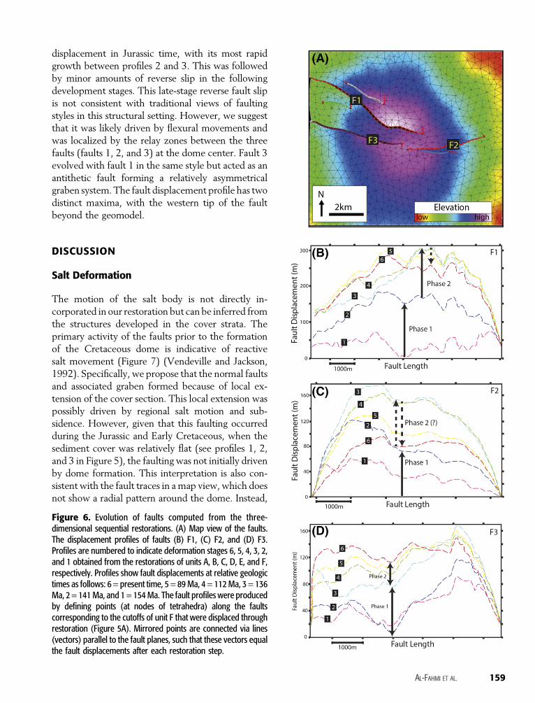
displacement in Jurassic time, with its most rapidgrowth between profiles 2 and 3. This was followedby minor amounts of reverse slip in the followingdevelopment stages. This late-stage reverse fault slipis not consistent with traditional views of faultingstyles in this structural setting. However, we suggestthat it was likely driven by flexural movements andwas localized by the relay zones between the threefaults (faults 1, 2, and 3) at the dome center. Fault 3evolved with fault 1 in the same style but acted as anantithetic fault forming a relatively asymmetricalgraben system. The fault displacement profile has twodistinct maxima, with the western tip of the faultbeyond the geomodel.
DISCUSSION
Salt Deformation
The motion of the salt body is not directly in-corporated in our restoration but can be inferred fromthe structures developed in the cover strata. Theprimary activity of the faults prior to the formationof the Cretaceous dome is indicative of reactivesalt movement (Figure 7) (Vendeville and Jackson,1992). Specifically, we propose that the normal faultsand associated graben formed because of local ex-tension of the cover section. This local extension waspossibly driven by regional salt motion and sub-sidence. However, given that this faulting occurredduring the Jurassic and Early Cretaceous, when thesediment cover was relatively flat (see profiles 1, 2,and 3 in Figure 5), the faulting was not initially drivenby dome formation. This interpretation is also con-sistent with the fault traces in amap view, which doesnot show a radial pattern around the dome. Instead,
Figure 6. Evolution of faults computed from the three-dimensional sequential restorations. (A) Map view of the faults.The displacement profiles of faults (B) F1, (C) F2, and (D) F3.Profiles are numbered to indicate deformation stages 6, 5, 4, 3, 2,and 1 obtained from the restorations of units A, B, C, D, E, and F,respectively. Profiles show fault displacements at relative geologictimes as follows: 6 = present time, 5 = 89 Ma, 4 = 112 Ma, 3 = 136Ma, 2 = 141Ma, and 1 = 154Ma. The fault profiles were producedby defining points (at nodes of tetrahedra) along the faultscorresponding to the cutoffs of unit F that were displaced throughrestoration (Figure 5A). Mirrored points are connected via lines(vectors) parallel to the fault planes, such that these vectors equalthe fault displacements after each restoration step.
AL-FAHMI ET AL. 159

the faults developed in a general east–west orientationthat presumably reflected the regional stress orien-tations within the sedimentary cover. In contrast, thecomplete radial distributions of normal faults arecommonly documented from areas of active salt di-apirism (e.g., Yin and Groshong, 2007).
We cannot directly resolve the nature of thecontact between the salt and the faults because of thedeterioration of the seismic imaging with depth.Thus, we are unable to assess whether the salt piercedthe overlying sediments or the faults offset the top ofthe salt. The modern dome is, however, low ampli-tude (gentle) in terms of bed dips and general cur-vature, as shown in profile 6 in Figure 5. Thedevelopment of a gently flexed dome suggests thatthe salt may be in a form of a pillow or low-reliefdiapir that localized in the region of the preexistingfaults. Given the long time of the growth and modestamplitude, the dome grew slowly, driven by eitherseparate or continuous pulses from moving salt. Wecannot exclude the possibility that the salt has gonethrough subtle phases of rise and withdrawal thatare beyond the temporal resolution of our model.Furthermore, the dome profiles show that the currentgeometry of the dome (red profiles) is not perfectlysymmetric, because equally distal ends of the domeare not at the same elevations. Structural asymmetrywas also present during previous time periods (seesections 1 and 2 in Figure 5). We suggest that thisasymmetry is at least in part a by-product of the faultdevelopment, particularly the development of agraben system in one side of the dome. The graben-bounding faults are visible from the dome profiles ofsection S1 in Figure 5B.
The salt growth and dome formation thatstarted in the Late Cretaceous and continued in the
Cenozoic may have been driven, in part, by the earlyplate contact between Arabia and Eurasia. The ini-tiation of the two-plate collision took place circa 64Ma, marked by the end of ophiolite obduction(Berberian and King, 1981). The collision of theplates resulted in the underthrusting of the Arabianplate during theOligocene, followed by thickening ofthe Arabian margin and uplift of Zagros during theMiocene (e.g., Mouthereau et al., 2012). Consistentwith this view, the dome structure including thestrain patterns calculated from our restoration iselongated with a major axis perpendicular to thegeneral northeast–southwest horizontal maximumcompressive stress (Shmax) orientation associatedwiththe Zagros compressional regime (Figure 8). Whileprecise early directions of the Zagros compressionalregime are uncertain, Shmax has remained at aroundN20° since the Neogene (e.g., Lacombe et al., 2011;McQuarrie and Van Hinsbergen, 2013).
Model Applications
The results from our applications of the 3-D geo-mechanical restorations demonstrated the capabilitiesto recover reasonable kinematic histories for struc-tures that involve salt. We described the restorationresults on the structural evolution of unit F, but resultsfrom other units can also be demonstrated from therestoredmodel in the same fashion. Unit F records thestructural evolution of both the dome and its asso-ciated faults spanning the Jurassic to present time.Results also benefit research on the salt tectonics ofthe eastern region of Arabia, particularly the Jurassicand Cretaceous section, which includes the mostprolific hydrocarbon reservoirs in the subsurface ofeasternArabia (e.g.,McGillivray andHusseini, 1992).
Figure 7. Example of experimental models (Vendeville and Jackson 1992, used with permission of Elsevier) used to explainreactive diapirism. Experiments after (A) 2 cm (0.79 in.) (2 h), (B) 3 cm (1.18 in.) (3 h), and (C) 5 cm (1.96 in.) (5 h) of total extension.The black substratum is viscous, which is less dense than its overburden. The uppermost white layer of uneven thickness ispostkinematic.
160 Geohorizon

Many hydrocarbon-bearing anticlines developed inthe Gulf region during the Cretaceous, despite thedifferent growth mechanisms presented in the liter-ature (e.g., Faqira et al., 2009; McGillivray andHusseini, 1992). Furthermore, the model results canhelp in the analyses of hydrocarbonmigration, charge,and possible reservoir fluid compartmentalization.The models can provide a context for subsequentinvestigations that aim to understand themechanismsand pathways of hydrocarbon charge, specifically byproviding constraints on the factors of faults, frac-tures, and capillary pore systems (e.g., Boles et al.,2004; Cartwright et al., 2007).
CONCLUSIONS
We demonstrated how 3-D geomechanical restora-tion methods could be applied to investigatethe tectonic history of a faulted, salt-related dome.Specifically, we applied these techniques to a domalstructure that forms a hydrocarbon field located ineastern Arabia. Focusing on the time window from
Jurassic to present day, we found that faultingdominated the area in the Jurassic and that faultscontinued with varying but lesser degrees of ac-tivity during the Cretaceous and Cenozoic. A low-amplitude dome formed in the Late Cretaceous,presumably caused by movement of the underlyingHormuz salt. Given that the faulting initiated beforethe folding,we interpret that the structure formed as areactive diapir. These results, although not explicitlymodeling salt deformation, suggest that 3-D geo-mechanical restoration methods can be applied todiscern viable geometric and kinematic histories ofsalt-involved structures.
The structure we analyzed is one of manyhydrocarbon-bearing anticlines developed in easternArabia during the Cretaceous. A range of differentgrowth mechanisms for these structures have beenpresented in the literature (e.g., Faqira et al., 2009;McGillivray and Husseini, 1992). Restoration resultscan help to distinguish between these differentgrowth mechanisms and also assist in the analyses ofhydrocarbonmigration, charge, and possible reservoirfluid compartmentalization.
Figure 8. Strain maps computed from the structural restoration model. (A) The dilation and (B) the distortions (first and secondinvariants of the strain tensor, respectively). The strain is cumulative for all stages (1–6) of restoration on the top surface of unit F. Strainpatterns are elongated along a northwest–southeast-trending axis, which is normal to the northeast–southwest-trending maximumcompressional stress orientation associated with the Arabia–Eurasia collision (Figure 1).
AL-FAHMI ET AL. 161

REFERENCES CITED
Al-Amri, A., 2013, Seismotectonics and seismogenic sourcezones of the Arabian Platform, in K. Al Hosani, F. Roure,R. Ellison, and S. Lokier, eds., Lithosphere dynamics andsedimentary basins: The Arabian plate and analogues:Berlin, Springer, p. 295–316, doi:10.1007/978-3-642-30609-9_15.
Allmendinger, R. W., 1998, Inverse and forward numericalmodeling of trishear fault-propagation folds: Tectonics, v.17, no. 4, p. 640–656, doi:10.1029/98TC01907.
Alsharhan, A. S., and A. E. M. Nairn, 1997, Sedimentarybasins and petroleum geology of the Middle East:Amsterdam,Elsevier, 843p., doi:10.1016/B978-044482465-3/50000-0.
Bahroudi, A., and H. A. Koyi, 2003, Effect of spatial distri-bution of Hormuz salt on deformation style in the Zagrosfold and thrust belt: An analogue modelling approach:Journal of the Geological Society, v. 160, no. 5,p. 719–733, doi:10.1144/0016-764902-135.
Berberian, M., and G. C. P. King, 1981, Towards a paleo-geography and tectonic evolution of Iran: Reply: Cana-dian Journal of Earth Sciences, v. 18, no. 11, p.1764–1766, doi:10.1139/e81-163.
Boles, J. R., P. Eichhubl, G. Garven, and J. Chen, 2004,Evolution of a hydrocarbon migration pathway alongbasin-bounding faults: Evidence from fault cement:AAPG Bulletin, v. 88, no. 7, p. 947–970, doi:10.1306/02090403040.
Bond,C. E.,D.Gibbs, Z.K. Shipton, andS. Jones, 2007,Whatdo you think this is? “Conceptual uncertainty” in geo-science interpretation:GSAToday, v. 17, no. 11, p. 4–10,doi:10.1130/GSAT01711A.1.
Callot, J. P., S. Jahani, and J. Letouzey, 2007, The role of pre-existing diapirs in fold and thrust belt development,Chapter 16, in O. Lacombe, J. Lave, F. Roure, andJ.Verges, eds., Thrust belts and forelandbasins. From foldkinematics to hydrocarbon system: Berlin, Springer,p. 309–325, doi:10.1007/978-3-540-69426-7_16.
Cartwright, J., M. Huuse, and A. Aplin, 2007, Seal bypasssystems: AAPG Bulletin, v. 91, no. 8, p. 1141–1166, doi:10.1306/04090705181.
Chamberlin, R. T., 1910, The Appalachian folds of centralPennsylvania: Journal of Geology, v. 18, no. 3, p. 228–251,doi:10.1086/621722.
Dahlstrom, C. D. A., 1969, Balanced cross sections: CanadianJournal of Earth Sciences, v. 6, no. 4, p. 743–757, doi:10.1139/e69-069.
de Santi, M. R., J. L. E. Campos, and L. F. Martha, 2003, 3-Dgeological restoration using a finite element approach:Gocad Proceedings: 23rd Gocad Meeting, AssociationScientifique pour laGeologie et ses Applications, p. 1–12.
Durand-Riard, P., G. Caumon, and P. Muron, 2010, Balancedrestoration of geological volumes with relaxed meshingconstraints: Computers & Geosciences, v. 36, p. 441–452,doi:10.1016/j.cageo.2009.07.007.
Durand-Riard, P., J. H. Shaw, A. Plesch, and G. Lufadeju,2013, Enabling 3D geomechanical restoration of strike-and oblique-slip faults using geological constraints,
with applications to the deep-water Niger Delta:Journal of Structural Geology, v. 48, p. 33–44, doi:10.1016/j.jsg.2012.12.009.
Edgell, H., 1991, Proterozoic salt basins of the Persian Gulfarea and their role in hydrocarbon generation: Precam-brian Research, v. 54, no. 1, p. 1–14, doi:10.1016/0301-9268(91)90065-I.
Erslev, E. A., 1991, Trishear fault-propagation folding:Geology, v. 19, no. 6, p. 617–620, doi:10.1130/0091-7613(1991)019<0617:TFPF>2.3.CO;2.
Faqira, M., M. Rademakers, and A. M. Afifi, 2009, New in-sights into the Hercynian orogeny, and their implicationsfor the Paleozoic hydrocarbon system in the Arabianplate: GeoArabia, v. 14, no. 3, p. 199–228.
Gibbs, A. D., 1983, Balanced cross-section construction fromseismic sections in areas of extensional tectonics: Journalof Structural Geology, v. 5, no. 2, p. 153–160, doi:10.1016/0191-8141(83)90040-8.
Gratier, J.-P., and B. Guillier, 1993, Compatibility constraintson folded and faulted strata and calculation of total dis-placement using computational restoration (UNFOLDprogram): Journal of Structural Geology, v. 15, no. 3–5,p. 391–402, doi:10.1016/0191-8141(93)90135-W.
Griffiths, P., S. Jones, N. Salter, F. Schaefer, R. Osfield, andH. Reiser, 2002, A new technique for 3-D flexural-sliprestoration: Journal of Structural Geology, v. 24, no. 4,p. 773–782, doi:10.1016/S0191-8141(01)00124-9.
Guzofski, C. A., J. P. Mueller, J. H. Shaw, P. Muron,D. A.Medwedeff, F. Bilotti, andC. Rivero, 2009, Insightsinto the mechanisms of fault-related folding provided byvolumetric structural restorations using spatially varyingmechanical constraints: AAPG Bulletin, v. 93, no. 4,p. 479–502, doi:10.1306/11250807130.
Kent, P. E., 1958, Recent studies of south Persian salt plugs:AAPGBulletin, v. 42, no. 12, p. 2951–2972, doi:10.1306/0BDA5C2D-16BD-11D7-8645000102C1865D.
Kent, P. E., 1979, The emergent Hormuz salt plugs of (Zagrosmountains), Southern Iran: Journal of Petroleum Geol-ogy, v. 2, no. 2, p. 117–144, doi:10.1111/j.1747-5457.1979.tb00698.x.
Konert, G., M. Afifi, S. A. Al-Hajri, and H. J. Droste, 2001,Paleozoic stratigraphy and hydrocarbon habitat of theArabian plate: GeoArabia, v. 6, p. 407–442.
Lacombe, O., N. Bellahsen, and F. Mouthereau, 2011,Fracture patterns in the Zagros Simply Folded Belt (Fars,Iran): Constraints on early collisional tectonic history androle of basement faults: Geological Magazine, v. 148,p. 940–963, doi:10.1017/S001675681100029X.
Lepage, F., 2003, Generation de maillages tridimensionnelspour la simulation des phenomenes physiques engeosciences, Ph.D. thesis, Institut National Poly-technique de Lorraine, Nancy, France, 254 p.
Li, Y., D. Jia, A. Plesch, J. Hubbard, J. H. Shaw, andM.Wang,2013, 3-D geomechanical restoration and paleomagneticanalysis of fault-related folds: An example from theYanjinggou anticline, southern Sichuan Basin: Journalof Structural Geology, v. 54, p. 199–214, doi:10.1016/j.jsg.2013.06.009.
162 Geohorizon
Lovely, P., E. Flodin, C. Guzofski, F. Maerten, andD. D. Pollard, 2012, Pitfalls among the promises ofmechanics-based restoration: Addressing implications ofunphysical boundary conditions: Journal of StructuralGeology, v. 41, p. 47–63, doi:10.1016/j.jsg.2012.02.020.
Maerten, L., and F. Maerten, 2006, Chronologic modeling offaulted and fractured reservoirs using geomechanicallybased restoration: Technique and industry applications:AAPG Bulletin, v. 90, no. 8, p. 1201–1226, doi:10.1306/02240605116.
Mallet, J.-L., 1992, Discrete smooth interpolation in geo-metric modelling: Computer AidedDesign, v. 24, no. 4,p. 178–191, doi:10.1016/0010-4485(92)90054-E.
McGillivray, J. G., and M. I. Husseini, 1992, The Paleozoicpetroleum geology of central Arabia: AAPG Bulletin,v. 76, p. 1473–1490, doi:10.1306/BDFF8A1A-1718-11D7-8645000102C1865D.
McQuarrie, N., and D. J. J. Van Hinsbergen, 2013, Retro-deforming the Arabia-Eurasia collision zone: Age ofcollision versus magnitude of continental subduction:Geology, v. 41, no. 3, p. 315–318, doi:10.1130/G33591.1.
Moretti, I., F. Lepage, andM. Guiton, 2006, KINE3D: A new3D restoration method based on a mixed approachlinking geometry and geomechanics: Oil & Gas Scienceand Technology, v. 61, no. 2, p. 277–289, doi:10.2516/ogst:2006021.
Mouthereau, F., O. Lacombe, and J. Verges, 2012, Buildingthe Zagros collisional orogen: Timing, strain distributionand the dynamics of Arabia/Eurasia plate convergence:Tectonophysics, v. 532-535, p. 27–60, doi:10.1016/j.tecto.2012.01.022.
Mueller, J. P., C. Guzofski, C. Rivero, J. H. Shaw, P. Muron,and F. Bilotti, 2005, New approaches to 3D structuralrestoration in fold-and-thrust belts using growth strata(abs.): AAPG Annual Meeting Program, Calgary, Alberta,accessedNovember3, 2015,http://www.searchanddiscovery.com/abstracts/html/2005/annual/abstracts/mueller.htm.
Muron, J.-P., J.-L. Mallet, and D. A. Medwedeff, 2005, 3Dsequential structural restoration: Geometry and kine-matics (abs.): AAPG Annual Meeting Program, Calgary,Alberta, accessed November 3, 2015, http://www.searchanddiscovery.com/abstracts/html/2005/annual/abstracts/muron.htm.
Papadrakakis, M., 1981, A method for the automatic evalu-ation of the dynamic relaxation parameters: ComputerMethods in Applied Mechanics and Engineering, v. 25,no. 1, p. 35–48, doi:10.1016/0045-7825(81)90066-9.
Plesch, A., J. H. Shaw, and D. Kronman, 2007, Mechanics oflow-relief detachment folding in the Bajiaochang field,Sichuan Basin, China: AAPG Bulletin, v. 91, no. 11,p. 1559–1575, doi:10.1306/06200706072.
Powers, R. W., L. F. Ramirez, C. D. Redmond, andE. L. J. Elberg, 1966, Geology of the Arabian Peninsulasedimentary geology of Saudi Arabia: U.S. GeologicalSurvey Professional Paper 560-D, 154 p.
Rouby, D., H. Xiao, and J. Suppe, 2000, 3-D restoration ofcomplexly folded and faulted surfaces using multipleunfolding mechanisms: AAPG Bulletin, v. 84, no. 6,p. 805–829, doi:10.1306/A9673400-1738-11D7-8645000102C1865D.
Rowan, M. G., and R. A. Ratliff, 2012, Cross-section resto-ration of salt-related deformation: Best practices andpotential pitfalls: Journal of Structural Geology, v. 41,p. 24–37, doi:10.1016/j.jsg.2011.12.012.
Searle, M., and J. Cox, 1999, Tectonic setting, origin, andobduction of the Oman ophiolite: Geological Society ofAmerica Bulletin, v. 111, no. 1, p. 104–122, doi:10.1130/0016-7606(1999)111<0104:TSOAOO>2.3.CO;2.
Sharland, P. R., R. Archer, D.M.Casey, R. B.Davies, S. H.Hall,A. P. Heward, A. D. Horbury, and M. D. Simmons, 2013,Arabian plate sequence stratigraphy: GeoArabia SpecialPublication 2, 371 p.
Shaw, J. H., S. C. Hook, and J. Suppe, 1994, Structural trendanalysis by axial surface mapping: AAPG Bulletin, v. 78,no. 5, p. 700–721, doi:10.1306/A25FE38D-171B-11D7-8645000102C1865D.
Talbot, C. J., 1998, Extrusions ofHormuz salt in Iran: London,Geological Society of London Special Publications 143,p. 315–334, doi:10.1144/GSL.SP.1998.143.01.21.
Talbot, C. J., and R. J. Jarvis, 1984, Age, budget and dynamicsof an active salt extrusion in Iran: Journal of StructuralGeology, v. 6, no. 5, p. 521–533, doi:10.1016/0191-8141(84)90062-2.
Vendeville, B. C., and M. P. A. Jackson, 1992, The rise ofdiapirs during thin-skinned extension: Marine and Pe-troleum Geology, v. 9, p. 354–371, doi:10.1016/0264-8172(92)90048-J.
Williams, G. D., S. J. Kane, T. S. Buddin, and A. J. Richards,1997, Restoration and balance of complex folded andfaulted rock volumes: Flexural flattening, jigsaw fittingand decompaction in three dimensions: Tectonophysics,v. 273, no. 3-4, p. 203–218, doi:10.1016/S0040-1951(96)00282-X.
Yin, H., and R. H. Groshong, 2007, A three-dimensionalkinematic model for the deformation above an activediapir: AAPG Bulletin, v. 91, no. 3, p. 343–363, doi:10.1306/10240606034.
Ziegler, M. A., 2001, Late Permian to Holocene paleofaciesevolution of the Arabian plate and its hydrocarbon oc-currences: GeoArabia, v. 6, no. 3, p. 445–504.
Zienkiewicz, O. C., R. L. Taylor, and J. Z. Zhu, 2005, Thefinite element method: Its basis and fundamentals, 6thed.: Oxford, Elsevier, 733 p.
AL-FAHMI ET AL. 163