geometric design of major/minor priority · pdf filegeometric design of major/minor priority...
TRANSCRIPT

Geometric Design of Major/Minor
Priority Junctions
Summary: This Document gives advice and standards for the geometric design of major /minor priority junctions with regard to traffic operation and safety.
THE HIGHWAYS AGENCY TD 42/95
THE SCOTTISH OFFICE DEVELOPMENT DEPARTMENT
THE WELSH OFFICE
Y SWYDDFA GYMREIG
THE DEPARTMENT OF THE ENVIRONMENT FOR
NORTHERN IRELAND

Volume 6 Section 2Part 6 TD 42/95 Registration of Amendments
ELECTRONIC COPY - NOT FOR USE OUTSIDE THE AGENCY
January 1995 PAPER COPIES OF THIS ELECTRONIC DOCUMENT ARE UNCONTROLLED
REGISTRATION OF AMENDMENTS
Amend Page No Signature & Date of Amend Page No Signature & Date ofNo incorporation of No incorporation of
amendments amendments

Volume 6 Section 2Registration of Amendments Part 6 TD 42/95
ELECTRONIC COPY - NOT FOR USE OUTSIDE THE AGENCY
PAPER COPIES OF THIS ELECTRONIC DOCUMENT ARE UNCONTROLLED January 1995
REGISTRATION OF AMENDMENTS
Amend Page No Signature & Date of Amend Page No Signature & Date ofNo incorporation of No incorporation of
amendments amendments

DESIGN MANUAL FOR ROADS AND BRIDGES
ELECTRONIC COPY - NOT FOR USE OUTSIDE THE AGENCY
January 1995 PAPER COPIES OF THIS ELECTRONIC DOCUMENT ARE UNCONTROLLED
VOLUME 6 ROAD GEOMETRYSECTION 2 JUNCTIONS
PART 6
TD 42/95
GEOMETRIC DESIGN OFMAJOR/MINOR PRIORITYJUNCTIONS
Contents
Chapter
1. Introduction
2. Form of Major/Minor Priority Junction
3. Siting of Major/Minor Priority Junctions
4. Safety
5. Road Users' Specific Requirements
6. Landscaping
7. Geometric Design Features
8. Assembly of Design Elements
9. References
10. Enquiries
Annex 1 Calculation of CapacityAnnex 2 Design of Channelising Islands
Volume 6 Section 2 Chapter 1Part 6 TD 42/95 Introduction
1. INTRODUCTION
e
e
General1.1 The treatment of major/minor priority junctionhas recently been the subject of a study sponsored bthe Department of Transport. This study reviewed theexisting advice given in Advice Note TA 20/84 on theLayout of Major/Minor Junctions , and maderecommendations on the amendments and additionsthe document based on research carried out since 19and on current good practice.
1.2 As a result of the study, this standard nowprovides details of the latest requirements andrecommendations on general design principles andsafety aspects of the geometric design of major/minopriority junctions.
1.3 This document replaces Advice Note TA20/84.
1.4 Guidance on the selection of the mostappropriate form of junction is given in TA 30 (DMRB5.1) and TA 23 (DMRB 6.2).
1.5 The main changes and additions from TA20/84 can be summarised as follows:-
a. Visibility requirements are mandatory (paras7.3 - 7.11).
b. The 15.5m long articulated goods vehicle witha single rear axle trailer has been replaced as the DeVehicle by the 16.5m long articulated vehicle (paras7.14 - 7.16).
c. The standard layouts in TA 20/84 have beenreplaced by figures which illustrate the design elemenand their assembly.
Scope
1.6 This Standard defines the main types ofmajor/minor priority junction which can be used on neand improved trunk roads.
1.7 Advice is also given on the choice between thdifferent types of major/minor priority junction, and onthe siting of such junctions.
ELECTRONIC COPY - NO
January 1995 PAPER COPIES OF THIS ELECT
Implementation
1.10 This Standard shall be used forthwith onall schemes for the construction, improvement andmaintenance of trunk roads, currently beingprepared provided that, in the opinion of theOverseeing Organisations, this would not result insignificant additional expense or delay progress.Design Organisations should confirm itsapplication to particular schemes with theOverseeing Organisation.
Definitions
1.11 The major road is the road to which isassigned a permanent priority of traffic movementover that of the other road or roads.
1.12 A minor road is a road which has to givepriority to the major road.
1.13 The three basic types of major/minorpriority junction on single carriageways are definedin the following paragraphs.
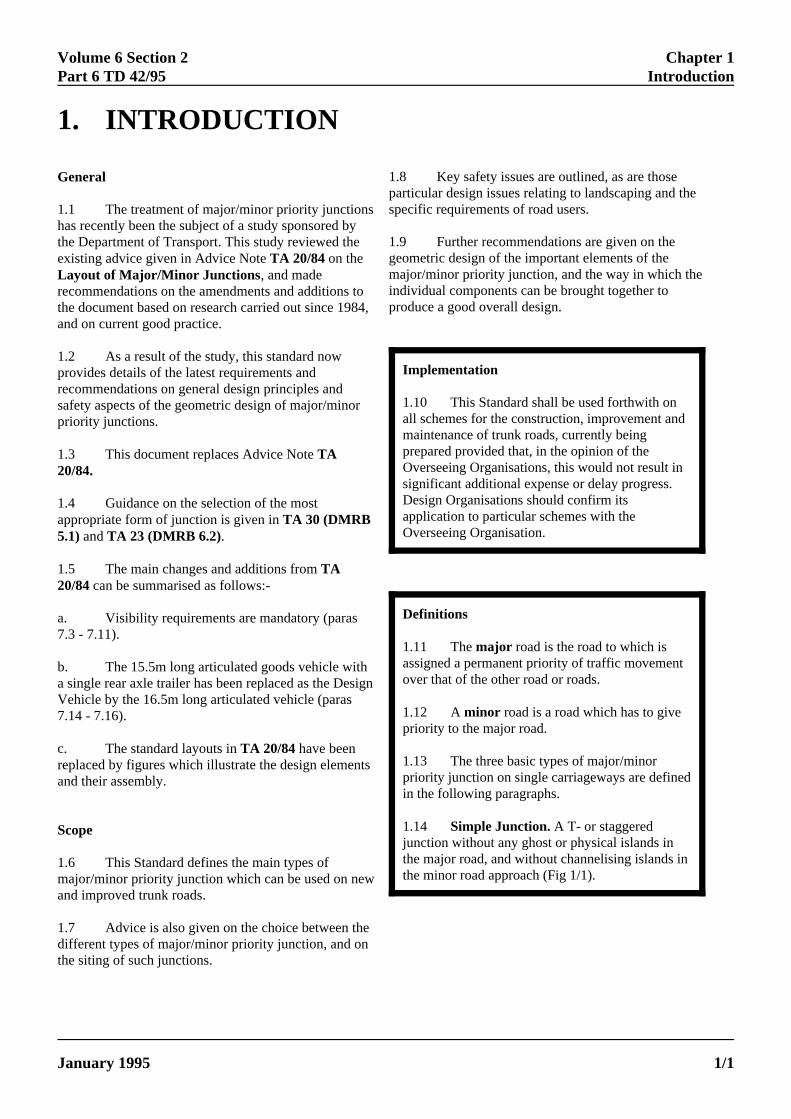
1.14 Simple Junction. A T- or staggeredjunction without any ghost or physical islands inthe major road, and without channelising islands inthe minor road approach (Fig 1/1).
sy
to84,
r
sign
ts
w
1.8 Key safety issues are outlined, as are thoseparticular design issues relating to landscaping and thspecific requirements of road users.
1.9 Further recommendations are given on thegeometric design of the important elements of themajor/minor priority junction, and the way in which theindividual components can be brought together toproduce a good overall design.
T FOR USE OUTSIDE THE AGENCY
RONIC DOCUMENT ARE UNCONTROLLED 1/1
Chapter 1 Volume 6 Section 2Introduction Part 6 TD 42/95
Figure 1/1 :Simple T-Junction(paras 1.14, 1.19)
ELECTRONIC COPY -
PAPER COPIES OF THIS ELE1/2
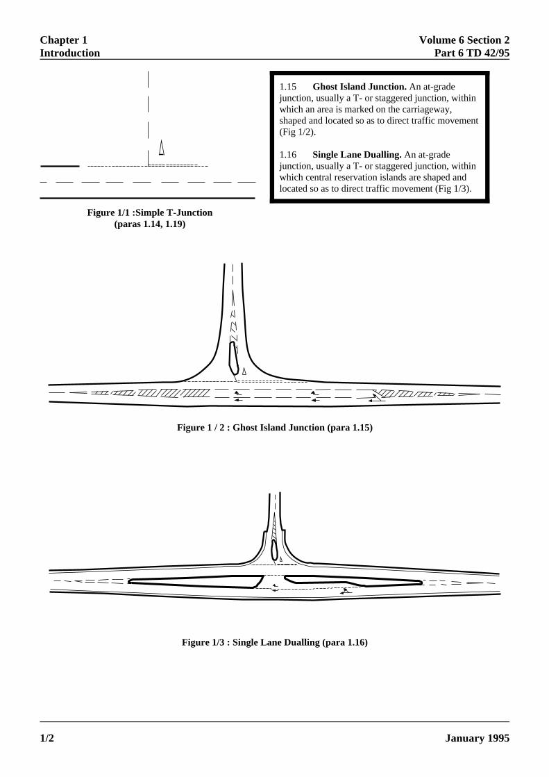
1.15 Ghost Island Junction. An at-gradejunction, usually a T- or staggered junction, withinwhich an area is marked on the carriageway,shaped and located so as to direct traffic movement(Fig 1/2).
1.16 Single Lane Dualling. An at-gradejunction, usually a T- or staggered junction, withinwhich central reservation islands are shaped andlocated so as to direct traffic movement (Fig 1/3).
Figure 1 / 2 : Ghost Island Junction (para 1.15)
Figure 1/3 : Single Lane Dualling (para 1.16)
NOT FOR USE OUTSIDE THE AGENCY
CTRONIC DOCUMENT ARE UNCONTROLLED January 1995
Volume 6 Section 2 Chapter 1Part 6 TD 42/95 Introduction
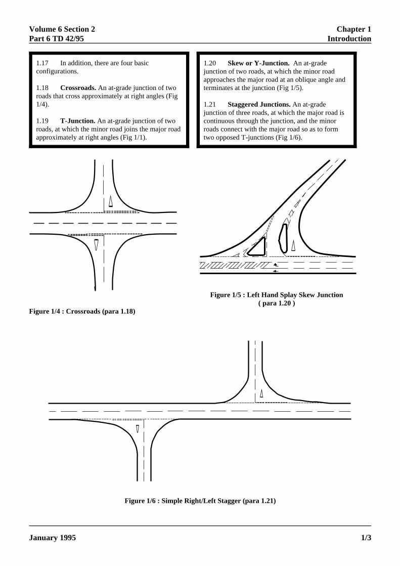
1.17 In addition, there are four basicconfigurations.
1.18 Crossroads. An at-grade junction of tworoads that cross approximately at right angles (Fig1/4).
1.19 T-Junction. An at-grade junction of tworoads, at which the minor road joins the major roadapproximately at right angles (Fig 1/1).
ELECTRONIC COPY - NOT
January 1995 PAPER COPIES OF THIS ELECTRO
1.20 Skew or Y-Junction. An at-gradejunction of two roads, at which the minor roadapproaches the major road at an oblique angle andterminates at the junction (Fig 1/5).
1.21 Staggered Junctions. An at-gradejunction of three roads, at which the major road iscontinuous through the junction, and the minorroads connect with the major road so as to formtwo opposed T-junctions (Fig 1/6).
Figure 1/4 : Crossroads (para 1.18)
Figure 1/5 : Left Hand Splay Skew Junction( para 1.20 )
Figure 1/6 : Simple Right/Left Stagger (para 1.21)
FOR USE OUTSIDE THE AGENCY
NIC DOCUMENT ARE UNCONTROLLED 1/3
Chapter 1 Volume 6 Section 2Introduction Part 6 TD 42/95
Mandatory Sections
1.22 Sections of this document which aremandatory standards which the OverseeingOrganisation expects in design, are highlighted bybeing contained in boxes. These are the sectionswith which the Design Organisation must complyor must have agreed a suitable departure with therelevant Overseeing Organisation. The remainderof the document contains advice and enlargementwhich is commended to designers for theirconsideration.
Relaxations
1.23 In dificult circumstances, the DesignOrganisation may relax a mandatory standard setout in this document to that relating to the nextlowest design speed step, unless this documentspecifically excludes it. However, in using anysuch relaxation, the Design Organisation shall givespecial attention to the effect this relaxation mayhave on the overall performance of the junction.This is particularly important in the situation wheretwo or more relaxtions are incorporated intodifferent components of the junction design. In allinstances of relaxations, the Design Organisationshall record the fact that a relaxation has been usedin the design and the corresponding reasons for itsuse. On completion of the design, the DesignOrganisation shall report all decisions to theOverseeing Organisation.
ELECTRONIC COPY - NOT
PAPER COPIES OF THIS ELECTRO1/4
Departures from Mandatory Standards
1.24 In very exceptional situations OverseeingOrganisations may be prepared to agree toDepartures from Mandatory Standards where theseseem unachievable. Design Organisations faced bysuch situations and wishing to consider pursuingthis course shall discuss any such option at an earlystage in design with the relevant OverseeingOrganisation. Proposals to adopt Departures fromStandard must be submitted by the DesignOrganisation to the Overseeing Organisation andformal approval received BEFORE incorporationinto a design layout to ensure that safety is notsignificantly reduced.
FOR USE OUTSIDE THE AGENCY
NIC DOCUMENT ARE UNCONTROLLED January 1995
Volume 6 Section 2 Chapter 2Part 6 TD 42/95 Form of Major/Minor Priority Junctions
2. FORM OF MAJOR/MINOR PRIORITYJUNCTIONS
s
General
2.1 Major/minor priority junctions are the mostcommon form of junction control. Traffic on the minorroad gives way to traffic on the major road and isnormally controlled by "Give Way" signs and roadmarkings. However, where there are severe visibilityrestrictions, "Stop" signs and road markings may beconsidered, with appropriate reference to the TrafficSigns Regulations and General Directions.
2.2 The advantage of all major/minor priorityjunctions is that through traffic on the major road is notdelayed. However, high major road speeds or thepossibility of major road overtaking traffic manoeuvresshould not be encouraged at major/minor priorityjunctions.
2.3 For more heavily used junctions, more compleforms of junction layout are required. Due to theuncertainty of traffic forecasting, designers shouldalways consider whether the layout they are designingcould be upgraded to provide more capacity, if thisshould prove necessary in the future.
Design Procedure
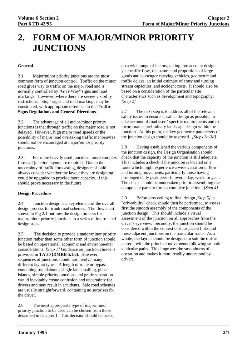
2.4 Junction design is a key element of the overalldesign process for trunk road schemes. The flow charshown in Fig 2/1 outlines the design process formajor/minor priority junctions in a series of interrelateddesign steps.
2.5 The decision to provide a major/minor priorityjunction rather than some other form of junction shouldbe based on operational, economic and environmentalconsiderations. [Step 1] Guidance on junction choice isprovided in TA 30 (DMRB 5.1.6). However,sequences of junctions should not involve manydifferent layout types. A length of route or bypasscontaining roundabouts, single lane dualling, ghostislands, simple priority junctions and grade separationwould inevitably create confusion and uncertainty fordrivers and may result in accidents. Safe road schemeare usually straightforward, containing no surprises forthe driver.
2.6 The most appropriate type of major/minorpriority junction to be used can be chosen from thosedescribed in Chapter 1. This decision should be based
oygtrsbc[S
2stainjuth
2thcTroapTc
2"dfijuadcthwpvod
ELECTRONIC COPY - NO
January 1995 PAPER COPIES OF THIS ELECTR
x
t
n a wide range of factors, taking into account designear traffic flow, the nature and proportions of largeoods and passenger carrying vehicles, geometric andaffic delays, an initial estimate of entry and turningtream capacities, and accident costs. It should also beased on a consideration of the particular siteharacteristics such as development and topography.tep 2]
.7 The next step is to address all of the relevantafety issues to ensure as safe a design as possible, toke account of road users' specific requirements and tocorporate a preliminary landscape design within thenction. At this point, the key geometric parameters ofe junction design should be assessed. [Steps 3a-3d]
.8 Having established the various components ofe junction design, the Design Organisation should
heck that the capacity of the junction is still adequate. his includes a check if the junction is located on aute which might experience a wide variation in flow
nd turning movements, particularly those havingrolonged daily peak periods, over a day, week, or year. he check should be undertaken prior to assembling theomponent parts to form a complete junction. [Step 4]
.9 Before proceeding to final design [Step 5], ariveability" check should then be performed, to assess
rst the smooth assembly of the components of thenction design. This should include a visualssessment of the junction on all approaches from theriver's eye view. Secondly, the junction should beonsidered within the context of its adjacent links andose adjacent junctions on the particular route. As ahole, the layout should be designed to suit the trafficattern, with the principal movements following smoothehicular paths. This improves the smoothness ofperation and makes it more readily understood byrivers.
T FOR USE OUTSIDE THE AGENCY
ONIC DOCUMENT ARE UNCONTROLLED 2/1
Chapter 2 Volume 6 Section 2Form of Major/Minor Priority Junctions Part 6 TD 42/95
2/2
Step 1Choose most appropriate type of junction
(TA 30/TA 23)
Major/Minor(TD 42 - This Document)
Step 2Choose most appropriate form andsize of major/minor priority junction
(Chapter 2)
NoIs
junction typeappropriate for site characteristics?
(Chapter 3)
Roundabout (TD 16)
Traffic Signals (TA 18)
Grade Separated- Full- Local (this doc)- Compact
(TD 22)(TD 42)(TD 40)
Yes
Step 3aAddress all relevant safety issues
(Chapter 4)
Step 3bTake account of road users '
specific requirements(Chapter 5)
1st iteration - go to step 3
2nd iteration - go to step 2
3rd iteration - go to step 1
Step 3cPreliminary landscape recommendations
(Chapter 6)
Step 3dAssess key geometric parameters
(Chapter 7)
Doesthe junction stillhave adequate
capacity ?
No
Yes
Step 4Assemble design elements
(Chapter 8)
NoIs
"driveability"thresholdsatisfied?
Yes
Step 5Final Design
Figure 2/1 : Flow Chart Outlining Design Procedure ( para 2.4 )
ELECTRONIC COPY - NOT FOR USE OUTSIDE THE AGENCY
PAPER COPIES OF THIS ELECTRONIC DOCUMENT ARE UNCONTROLLED January 1995
Volume 6 Section 2 Chapter 2Part 6 TD 42/95 Form of Major/Minor Priority Junctions
2.10 If, at any point in the design procedure, thejunction design is unsatisfactory, then the designershould return to the previous step in the procedure torefine the design. In certain extreme cases, this procecould result in a change in junction type or form.
C
2jrsi
ELECTRONIC COPY - NO
January 1995 PAPER COPIES OF THIS ELECTR
ss
hoice of Major/Minor Priority Junction
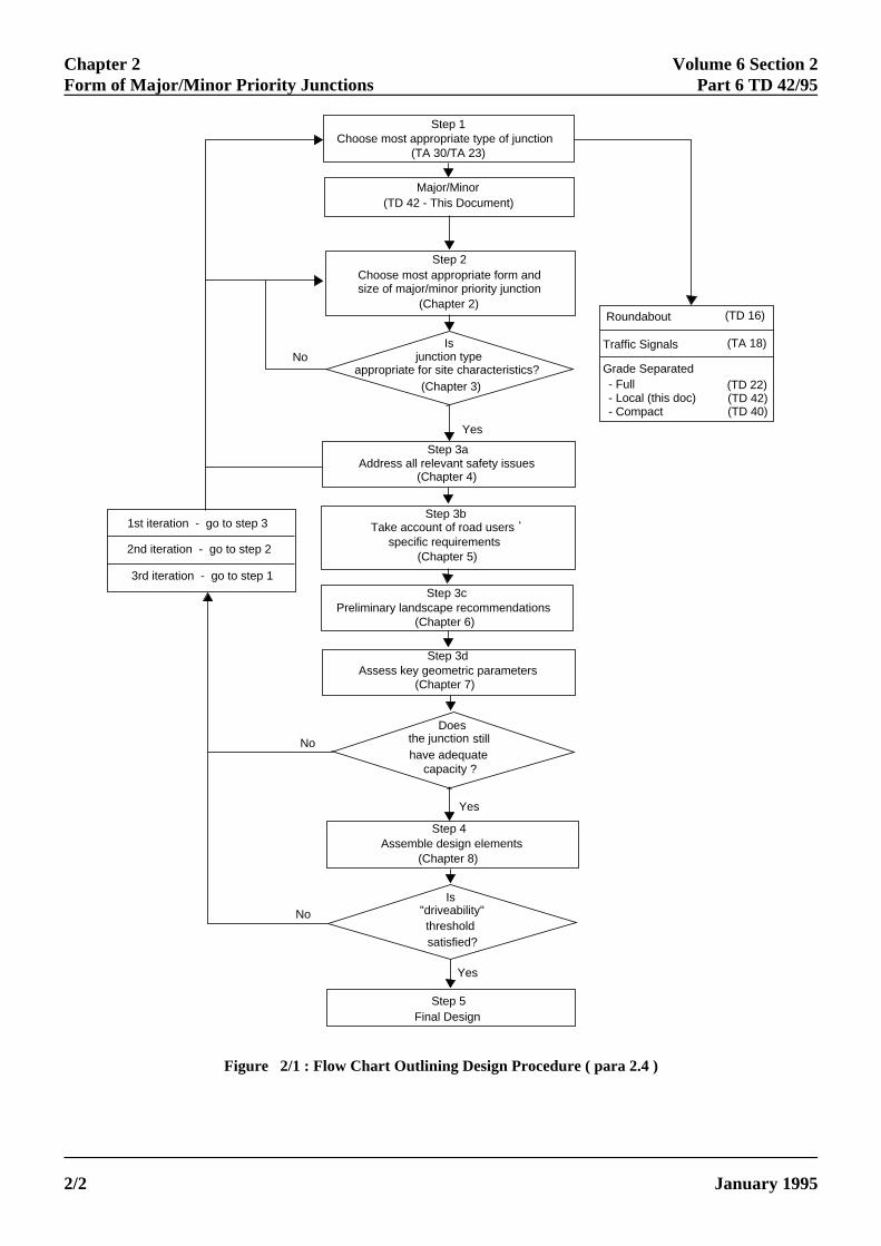
.11 Table 2/1 shows the major/minor priorityunction forms considered suitable for various majoroad carriageway types in both urban and ruralituations. This Table should be used as a starting point
n choosing the most appropriate type of major/minorpriority junction to use at a particular site.
Carriageway TypeJunction Type
Simple Ghost Island Dualling
Standard Location ; ;= > ; ;= > ; ;= >
S2 Urban Yes Yes Maybe Yes Yes No Yes Yes No(D1) (D1)
Rural Yes Yes Maybe Yes Yes No Yes Yes No(D1) (D1)
WS2 Urban No No No Yes Yes No Yes Yes No(D1) (D1)
Rural No No No Yes Yes No Yes Yes No(D1) (D1)
D2 Urban No No No No No No Yes Yes No(D2) (D2)
Rural No No No No No No Yes Yes No(D2) (D2)
D3 No No No No No No No No No
; T Junction ;= Staggered Junction > Crossroads
Table 2/1: Possible Junction Types for Different Major Road Carriageway Types
T FOR USE OUTSIDE THE AGENCY
ONIC DOCUMENT ARE UNCONTROLLED 2/3
Chapter 2 Volume 6 Section 2Form of Major/Minor Priority Junctions Part 6 TD 42/95
ly
ion the ifhen
itialustify a
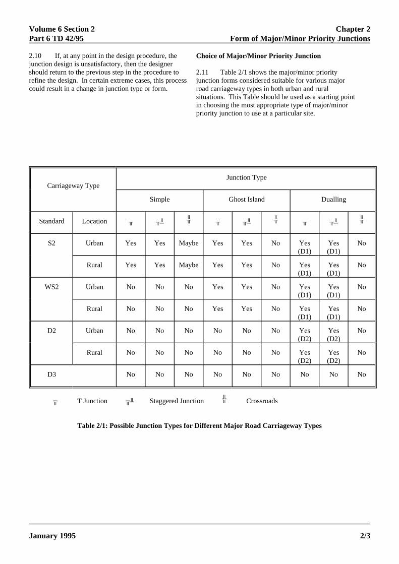
2.12 Fig 2/2 may be useful when considering furthethe options for a site. For single carriageway roads itshows approximately the various levels of T-junctionwhich may be applicable for different combinations offlows. The information takes into account geometricand traffic delays, entry and turning traffic flows, andaccident costs. However, it must be noted that Fig 2/2gives the starting point for junction choice and there arother factors such as those indicated in para 2.6 to beconsidered before a final decision is made.
2
ELECTRONIC COPY - NOT
PAPER COPIES OF THIS ELECTR2/4
r 2.13 Ordinarily, the 2-way Annual Average DaiTraffic (AADT) design year flows are used to
determine the approximate level of junction provisfor new junctions. However, if there is evidence inarea of the junction of high seasonal variations, orshort, intense peaks in the traffic flows are likely, t
consideration should be given to using either thee appropriate seasonal or peak hour flows in the in
capacity assessment detailed in para 2.6, or to jdifferent type of junction.
.14 The following principles can be identified fromTable 2/1 and Fig 2/2.
Minor Road Flow (2-way AADT)
8,000
7,000
6,000
5,000
4,000
3,000
2,000
1,000
0
0 5,000 10,000 15,000 20,000
Roundabout(or other type)
Single LaneDualling
Ghost Island
Simple
Major Road Flow (2- way AADT)
Figure 2/2 : Approximate Level of Provision of T-junctions on New Single Carriageway Roads for VariousMajor and Minor Road Design Year Traffic Flows ( paras 2.2, 2.14 )
FOR USE OUTSIDE THE AGENCY
ONIC DOCUMENT ARE UNCONTROLLED January 1995
Volume 6 Section 2 Chapter 2Part 6 TD 42/95 Form of Major/Minor Priority Junctions
t
,
Simple
2.15 Simple junctions are appropriate formost minor junctions on single carriagewayroads, but must not be used for wide singlecarriageways or dual carriageways. For newrural junctions they shall only be used when thedesign flow in the minor road is not expected toexceed about 300 vehicles 2-way AADT, andthat on the major road is not expected to exceed13,000 vehicles 2-way AADT.
2.16 At existing rural, and at urban junctionsthe cost of upgrading a simple junction toprovide a right turning facility will vary from siteto site. However, upgrading should always beconsidered where the minor road flow exceeds500 vehicles 2-way AADT, a right turningaccident problem is evident, or where vehicleswaiting on the major road to turn right inhibit thethrough flow and create a hazard.
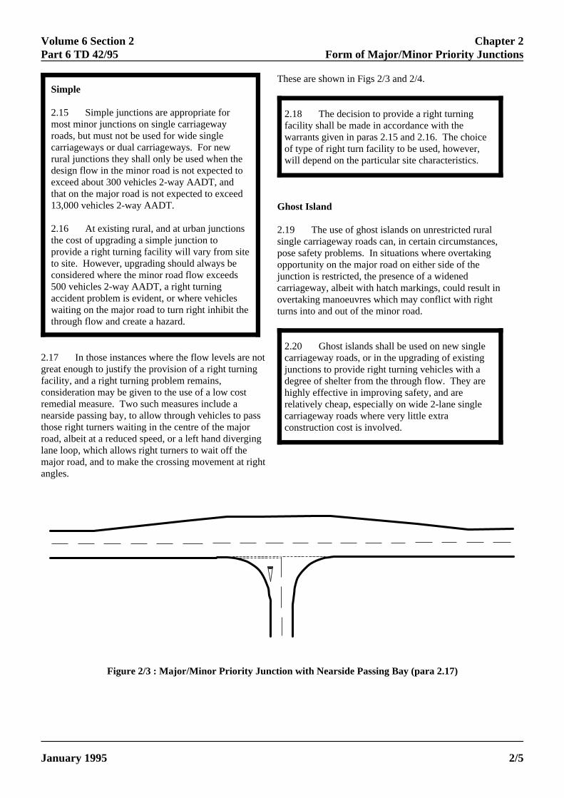
2.17 In those instances where the flow levels are nogreat enough to justify the provision of a right turningfacility, and a right turning problem remains,consideration may be given to the use of a low costremedial measure. Two such measures include anearside passing bay, to allow through vehicles to passthose right turners waiting in the centre of the majorroad, albeit at a reduced speed, or a left hand diverginlane loop, which allows right turners to wait off themajor road, and to make the crossing movement at righ
T
G
2spojucotu
ELECTRONIC COPY - NOT
January 1995 PAPER COPIES OF THIS ELECTRO
angles.
2.18 The decision to provide a right turningfacility shall be made in accordance with thewarrants given in paras 2.15 and 2.16. The choiceof type of right turn facility to be used, however,will depend on the particular site characteristics.
2.20 Ghost islands shall be used on new singlecarriageway roads, or in the upgrading of existingjunctions to provide right turning vehicles with adegree of shelter from the through flow. They arehighly effective in improving safety, and arerelatively cheap, especially on wide 2-lane singlecarriageway roads where very little extraconstruction cost is involved.
t
g
hese are shown in Figs 2/3 and 2/4.
host Island
.19 The use of ghost islands on unrestricted ruralingle carriageway roads can, in certain circumstancesose safety problems. In situations where overtakingpportunity on the major road on either side of thenction is restricted, the presence of a widened
arriageway, albeit with hatch markings, could result invertaking manoeuvres which may conflict with rightrns into and out of the minor road.
Figure 2/3 : Major/Minor Priority Junction with Nearside Passing Bay (para 2.17)
FOR USE OUTSIDE THE AGENCY
NIC DOCUMENT ARE UNCONTROLLED 2/5

Chapter 2 Volume 6 Section 2Form of Major/Minor Priority Junctions Part 6 TD 42/95
Figure 2/4 : Major / Minor Priority Junction with Left Hand Diverging Lane Loop for Right Turns( para 2.17 )
2.21 Ghost islands shall not be used whereovertaking opportunities on adjacent links arerestricted or where traffic turning right out of theminor road would need to make this manoeuvre intwo stages.
2.23 Single lane dualling shall normally beused on rural single carriageway roads that havegood overtaking opportunities on adjacent links,and shall be used in preference to ghost islandswhere overtaking opportunities on adjacent linksare restricted and where traffic turning right out ofthe minor road would need to make thismanoeuvre in two stages. Because of the detailednature of the single lane dualling layout, it is onlyappropriate for roads with hard strips.
Single Lane Dualling
2.22 Single lane dualling can be used on unrestricterural single carriageway roads to prevent overtaking onthe major road, and/or where it is desirable for the righturn out of the minor road to be carried out in twostages. However, even though overtaking is preventewhen major road drivers are presented with animproved highway layout and standard there may be atendency to speed up through the junction where slowmoving vehicles may be crossing or turning. Consequently, care needs to be taken when siting thistype of junction, particularly at the start of ruralbypasses.
2mtfauisvnioroz
ELECTRONIC COPY - NO
PAPER COPIES OF THIS ELECT2/6
2.24 There are certain conditions under which asingle lane dualling layout may be misinterpreted bydrivers. Where a road contains alternating singleand dual carriageway sections, a single lane duallinglayout might lead drivers into mistaking the width ofdivided carriageway at the junction to think they areapproaching a fully dualled section with overtakingopportunities. In addition, where a junction isproposed on a single carriageway within about 3kilometres of the taper from a long length of dualcarriageway, there may also be confusion if singlelane dualling is introduced. In both of these cases,single lane dualling shall not be used. Single lanedualling shall not be used where there is a climbinglane in one direction through the junction.
d
t
d,
.25 Single lane dualling is formed by widening theajor road to provide a central reservation, a right
urning lane and space for vehicles waiting to turn rightrom the major road into the minor road (Fig 2/3). Theylso enable drivers of vehicles of nearly all lengths tondertake the right turn manoeuvre from the minor road
n two stages. The limiting factor is the left handideways visibility from the driver's seat, which can beery restricted in some cabs and leaves the driver witho option but to make the manoeuvre in one stage. An
mportant feature of this type of junction is that there isnly one through lane in each direction on the majoroad. This form of junction is designed to preventvertaking and excessive speeds through the conflictones.
T FOR USE OUTSIDE THE AGENCY
RONIC DOCUMENT ARE UNCONTROLLED January 1995
Volume 6 Section 2 Chapter 2Part 6 TD 42/95 Form of Major/Minor Priority Junctions
theingle
w on
.
to
nd
d
However, short lengths of full dualling (D2AP) justto incorporate a junction on otherwise singlecarriageway roads shall not be provided.
Dual Carriageway Junctions
2.26 Major/minor priority junctions may also beused on dual carriageway, but should never be providedon D3AP roads. The upper limit for minor road flowsshould be taken as about 3,000 vehicles AADT 2-waywhen considering providing a major/minor priorityjunction on continuous D2AP roads in rural areas.
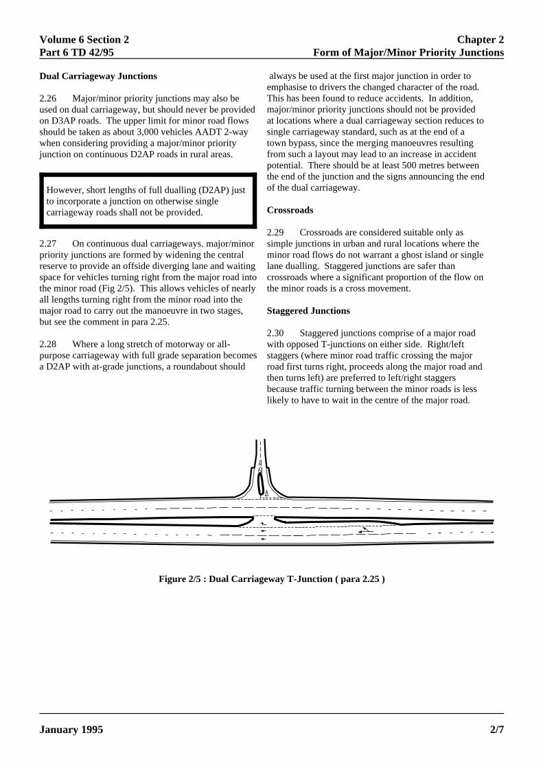
2.27 On continuous dual carriageways. major/minorpriority junctions are formed by widening the centralreserve to provide an offside diverging lane and waitingspace for vehicles turning right from the major road intothe minor road (Fig 2/5). This allows vehicles of nearlyall lengths turning right from the minor road into themajor road to carry out the manoeuvre in two stages,but see the comment in para 2.25.
2.28 Where a long stretch of motorway or all-purpose carriageway with full grade separation becomea D2AP with at-grade junctions, a roundabout should
alemThmaat sintowfropotheof
Cr
2.2
St
2.3wistaroathebelik
ELECTRONIC COPY - NOT
January 1995 PAPER COPIES OF THIS ELECTRO
simple junctions in urban and rural locations whereminor road flows do not warrant a ghost island or slane dualling. Staggered junctions are safer thancrossroads where a significant proportion of the flothe minor roads is a cross movement.
s
ways be used at the first major junction in order tophasise to drivers the changed character of the roadis has been found to reduce accidents. In addition,jor/minor priority junctions should not be providedlocations where a dual carriageway section reduces gle carriageway standard, such as at the end of an bypass, since the merging manoeuvres resulting
m such a layout may lead to an increase in accidenttential. There should be at least 500 metres betwee end of the junction and the signs announcing the en
the dual carriageway.
ossroads
9 Crossroads are considered suitable only as
aggered Junctions
0 Staggered junctions comprise of a major roadth opposed T-junctions on either side. Right/leftggers (where minor road traffic crossing the majord first turns right, proceeds along the major road ann turns left) are preferred to left/right staggers
cause traffic turning between the minor roads is lessely to have to wait in the centre of the major road.
Figure 2/5 : Dual Carriageway T-Junction ( para 2.25 )
FOR USE OUTSIDE THE AGENCY
NIC DOCUMENT ARE UNCONTROLLED 2/7

Chapter 2 Volume 6 Section 2Form of Major/Minor Priority Junctions Part 6 TD 42/95
Capacity Assessment
2.31 For design involving flows greater than the lowflows described in the preceding paragraphs, use shoube made of the equations which are available for theprediction of possible minor road entry flows into amajor/minor priority junction as a function of theflow/geometry at the junction. These equations arereproduced at Annex 1 and are applicable to all types omajor/minor priority junctions including staggeredjunctions.
2bC7c1Tth
2P
ELECTRONIC COPY - NOT F
PAPER COPIES OF THIS ELECTRO2/8
.
ld
f
.32 The range of reference flows developed shoulde used to produce trial designs for assessment. onsideration of a lower flow to capacity ratio (RFC) of5% is recommended in Annex 1 as a general rule whenonsidering single carriageways with design speeds of00 kph and above or high speed dual carriageways. his is because formulae have not been developed forese latter types of road.
.33 Manual or computerised methods such asICADY/3 may be used to assess capacity. It is not
realistic to calculate queue lengths and delays manually
OR USE OUTSIDE THE AGENCY
NIC DOCUMENT ARE UNCONTROLLED January 1995
Volume 6 Section 2 Chapter 3Part 6 TD 42/95 Siting of Major/Minor Priority Junctions
3. SITING OF MAJOR/MINOR PRIORITYJUNCTIONS
.
General
3.1 On new single carriageways where overtakingopportunity is limited, ghost island and single lanedualling junctions should be sited on non-overtakingsections, as defined in Departmental Standard TD 9(DMRB 6.1.1). On existing single carriageway roadsalong which overtaking opportunity is very limited, theisolated local improvement of a junction to a ghost islandcould induce unsafe driver behaviour, since the shortlength of wider road thus created may be used by somefrustrated drivers for overtaking.
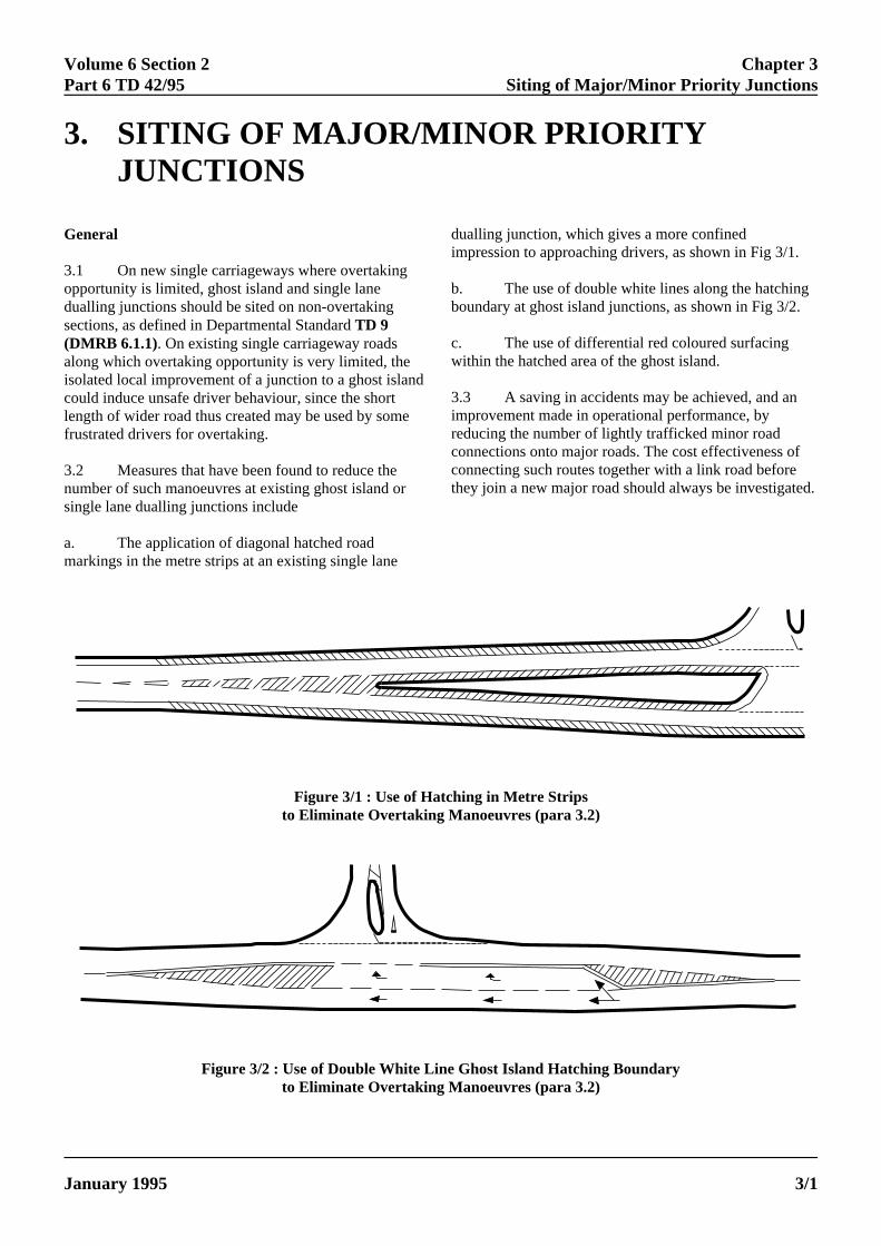
3.2 Measures that have been found to reduce thenumber of such manoeuvres at existing ghost island orsingle lane dualling junctions include
a. The application of diagonal hatched roadmarkings in the metre strips at an existing single lane
duim
b.bo
c.w
3.imrecocoth
ELECTRONIC COPY - NOT FO
January 1995 PAPER COPIES OF THIS ELECTRON
alling junction, which gives a more confinedpression to approaching drivers, as shown in Fig 3/1.
The use of double white lines along the hatchingundary at ghost island junctions, as shown in Fig 3/2.
The use of differential red coloured surfacingithin the hatched area of the ghost island.
3 A saving in accidents may be achieved, and anprovement made in operational performance, byducing the number of lightly trafficked minor roadnnections onto major roads. The cost effectiveness ofnnecting such routes together with a link road beforeey join a new major road should always be investigated
Figure 3/1 : Use of Hatching in Metre Stripsto Eliminate Overtaking Manoeuvres (para 3.2)
Figure 3/2 : Use of Double White Line Ghost Island Hatching Boundaryto Eliminate Overtaking Manoeuvres (para 3.2)
R USE OUTSIDE THE AGENCY
IC DOCUMENT ARE UNCONTROLLED 3/1
Chapter 3 Volume 6 Section 2Siting of Major/Minor Priority Junctions Part 6 TD 42/95
Ica
Horizontal Alignment
3.4 Ideally, major/minor priority junctions shouldnot be sited where the major road is on a sharp curve.However, where the siting of a major/minor priorityjunction on a curve is unavoidable, the preferredalignment is where T-junctions are sited with the minorroad on the outside of the curve. This is especiallyimportant for junctions on climbing lane sections ordual carriageways, to ensure that minor road traffic hasa clear view of vehicles on the major road that may beovertaking through the junction. Junctions on the insideof sharp curves are most undesirable.
3.5 Problems have been experienced withmajor/minor priority junctions containing a skew minorroad at the end of some town bypasses where thealignment is such that some drivers perceive that theminor road retains priority. In such circumstances, theminor road approach should be aligned so as to join themajor road as near to right angles as possible in order toeliminate any driver confusion as to which route haspriority.
Vertical Alignment
3.6 The best locations for junctions are on levelground, or where the gradient of the approaches doesnot exceed 2% either uphill or downhill. Downhillapproaches in excess of this figure, particularly on highspeed roads, can induce traffic speeds above thosedesirable through the junction, and lead to amisjudgment of the approach speed by drivers enteringfrom the minor road. Uphill approaches are alsoundesirable since it is difficult for drivers to appreciatethe layout of a junction when they are approaching it onan up gradient. They cannot see the full layout from thelengths immediately on either side of the crest.
3.7onpegaThapinc"G
3.8lanforthesupinsabfroimmduFigsituwhmaapIn pethethe
ELECTRONIC COPY - NOT
PAPER COPIES OF THIS ELECTRO3/2
n such circumstances, a designer shall attempt toreate a level section of at least 15 metres lengthdjacent to the major road.
Where the minor road approaches the junction an uphill gradient, drivers can often wronglyrceive the junction form, and will require a longerp between vehicles to pull out onto the major road.is is undesirable, as is the case where the minor roadproaches a junction on a downhill gradient, thusreasing the likelihood of vehicles overrunning theive Way" line.
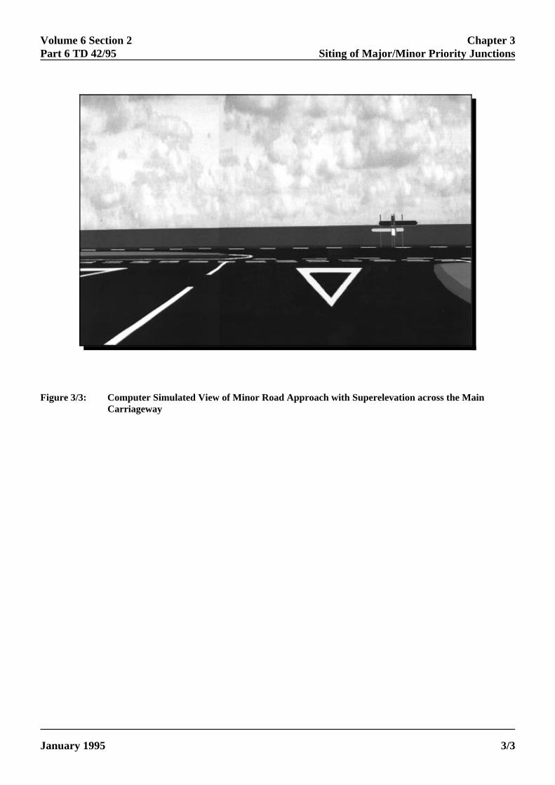
Sections in the central reserve opening at singlee dualling and dual carriageway junctions should fall drainage purposes, towards rather than away from, minor road, particularly where there iserelevation across the main carriageway. In such
tances where this does not occur, drivers may not bele to see the full width of the furthest carriagewaym their position on the minor road. They may not
ediately appreciate the road they are joining is aal carriageway, particularly with single lane dualling. 3/3 shows a computer simulated view of thisation. A form of optical illusion may also be created,
ereby the width available in the central reserve, toke the right turn out of the minor road in two stages,pears insufficient to accommodate waiting vehicles.this situation the minor road driver may attempt torform the manoeuvre in one stage. It is better to have outside edge of each superelevated carriageway at same level.
FOR USE OUTSIDE THE AGENCY
NIC DOCUMENT ARE UNCONTROLLED January 1995
Volume 6 Section 2 Chapter 3Part 6 TD 42/95 Siting of Major/Minor Priority Junctions
Figure 3/3: Computer Simulated View of Minor Road Approach with Superelevation across the MainCarriageway
ELECTRONIC COPY - NOT FOR USE OUTSIDE THE AGENCY
January 1995 PAPER COPIES OF THIS ELECTRONIC DOCUMENT ARE UNCONTROLLED 3/3
Volume 6 Section 2 Chapter 4Part 6 TD 42/95 Safety
4. SAFETY
rips give
rs and
theasd
nsirableway
nce.
id
ity
areas.
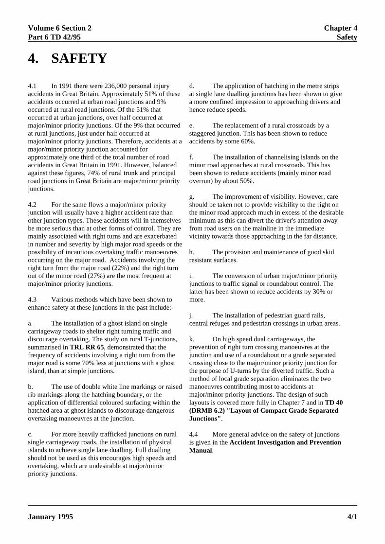
4.1 In 1991 there were 236,000 personal injuryaccidents in Great Britain. Approximately 51% of theseaccidents occurred at urban road junctions and 9%occurred at rural road junctions. Of the 51% thatoccurred at urban junctions, over half occurred atmajor/minor priority junctions. Of the 9% that occurredat rural junctions, just under half occurred atmajor/minor priority junctions. Therefore, accidents at amajor/minor priority junction accounted forapproximately one third of the total number of roadaccidents in Great Britain in 1991. However, balancedagainst these figures, 74% of rural trunk and principalroad junctions in Great Britain are major/minor priorityjunctions.
4.2 For the same flows a major/minor priorityjunction will usually have a higher accident rate thanother junction types. These accidents will in themselvesbe more serious than at other forms of control. They aremainly associated with right turns and are exacerbatedin number and severity by high major road speeds or thpossibility of incautious overtaking traffic manoeuvresoccurring on the major road. Accidents involving theright turn from the major road (22%) and the right turnout of the minor road (27%) are the most frequent atmajor/minor priority junctions. j
4.3 Various methods which have been shown toenhance safety at these junctions in the past include:-
a. The installation of a ghost island on singlecarriageway roads to shelter right turning traffic anddiscourage overtaking. The study on rural T-junctions,summarised in TRL RR 65, demonstrated that thefrequency of accidents involving a right turn from themajor road is some 70% less at junctions with a ghostisland, than at simple junctions.
b. The use of double white line markings or raisedrib markings along the hatching boundary, or theapplication of differential coloured surfacing within thehatched area at ghost islands to discourage dangerousovertaking manoeuvres at the junction.
c. For more heavily trafficked junctions on ruralsingle carriageway roads, the installation of physicalislands to achieve single lane dualling. Full duallingshould not be used as this encourages high speeds andovertaking, which are undesirable at major/minorpriority junctions.
g.
la
j.
prjucrthmmm
(DJu
4.is M
ELECTRONIC COPY - NOT
January 1995 PAPER COPIES OF THIS ELECTR
d. The application of hatching in the metre stat single lane dualling junctions has been shown toa more confined impression to approaching drive
hence reduce speeds.
e. The replacement of a rural crossroads by astaggered junction. This has been shown to reduceaccidents by some 60%.
f. The installation of channelising islands on minor road approaches at rural crossroads. This hbeen shown to reduce accidents (mainly minor roa
overrun) by about 50%.
should be taken not to provide visibility to the right othe minor road approach much in excess of the deminimum as this can divert the driver's attention afrom road users on the mainline in the immediatevicinity towards those approaching in the far dista
eh. The provision and maintenance of good skresistant surfaces.
i. The conversion of urban major/minor priorunctions to traffic signal or roundabout control. The
more.
central refuges and pedestrian crossings in urban
k. On high speed dual carriageways, the
layouts is covered more fully in Chapter 7 and in TD 40
The improvement of visibility. However, care
tter has been shown to reduce accidents by 30% or
The installation of pedestrian guard rails,
evention of right turn crossing manoeuvres at thenction and use of a roundabout or a grade separatedossing close to the major/minor priority junction fore purpose of U-turns by the diverted traffic. Such aethod of local grade separation eliminates the twoanoeuvres contributing most to accidents atajor/minor priority junctions. The design of such
RMB 6.2) "Layout of Compact Grade Separatednctions".
4 More general advice on the safety of junctionsgiven in the Accident Investigation and Preventionanual.
FOR USE OUTSIDE THE AGENCY
ONIC DOCUMENT ARE UNCONTROLLED 4/1
Volume 6 Section 2 Chapter 5Part 6 TD 42/95 Road Users’ Specific Requirements
5. ROAD USERS’ SPECIFIC REQUIREMENTS
re.
General
5.1 In designing major/minor priority junctions, itis important to take account of the specific requiremeof road users. The high speed nature of rural trunk rois such that specific facilities may be required at somlocations in order to ensure the safe passage of specroad users through the junction. This is equally true asome urban sites where some junctions may be usedintensively by all types of road user.
Cyclists' Facilities
5.2 Major/minor priority junctions present a hazafor pedal cyclists, and 73% of cyclist accidents atjunctions occur at major/minor priority junctions. It istherefore important that a cyclist is provided with a sapassage through the junction, and that the design of cyclist facilities should take into account both theirvehicular rights and their particular vulnerability, assuggested by the accident statistics.
ELECTRONIC COPY - N
January 1995 PAPER COPIES OF THIS ELEC
ntsadseifict
rd
feany
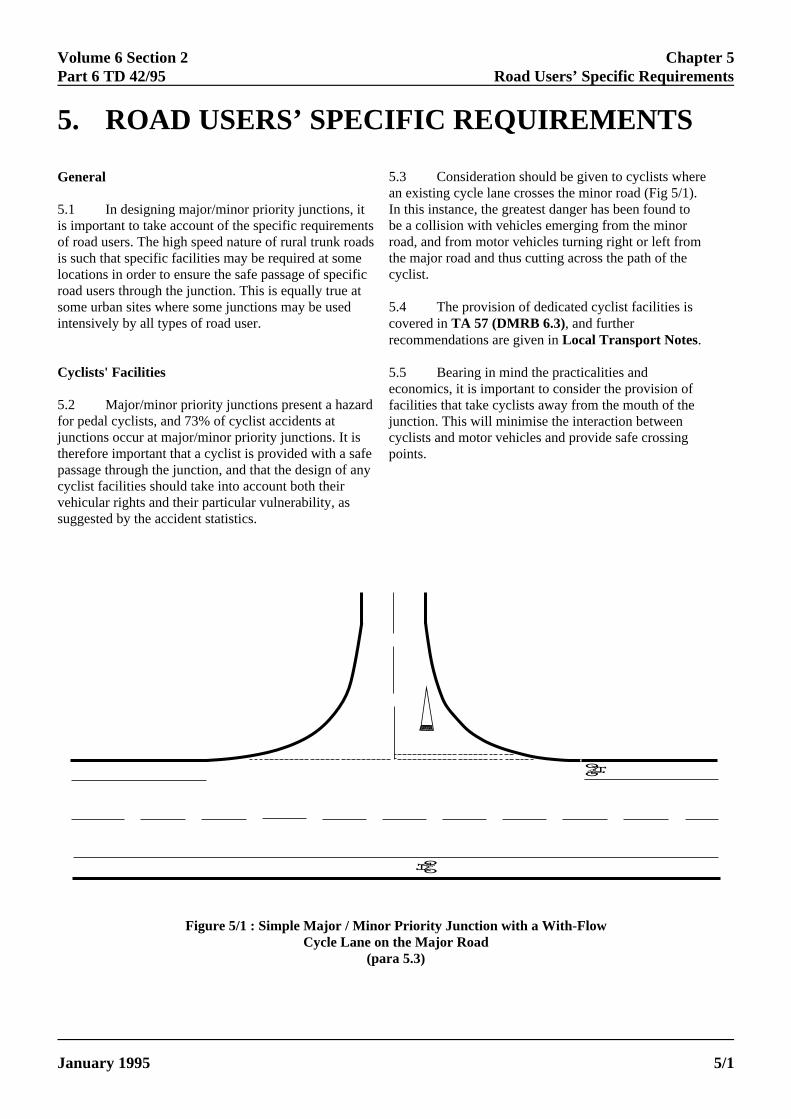
5.3 Consideration should be given to cyclists whean existing cycle lane crosses the minor road (Fig 5/1)In this instance, the greatest danger has been found tobe a collision with vehicles emerging from the minorroad, and from motor vehicles turning right or left fromthe major road and thus cutting across the path of thecyclist.
5.4 The provision of dedicated cyclist facilities iscovered in TA 57 (DMRB 6.3), and furtherrecommendations are given in Local Transport Notes.
5.5 Bearing in mind the practicalities andeconomics, it is important to consider the provision offacilities that take cyclists away from the mouth of thejunction. This will minimise the interaction betweencyclists and motor vehicles and provide safe crossingpoints.
Figure 5/1 : Simple Major / Minor Priority Junction with a With-FlowCycle Lane on the Major Road
(para 5.3)
OT FOR USE OUTSIDE THE AGENCY
TRONIC DOCUMENT ARE UNCONTROLLED 5/1
Chapter 5 Volume 6 Section 2Road Users’ Specific Requirements Part 6 TD 42/95
d
5.6 Such facilities may include the following:-
a. Shared use by pedestrians and cyclists of adisplaced cycle track/footway with a controlled oruncontrolled crossing.
b. A signposted alternative cycle route away fromthe junction.
c. Full grade separation, for example by means ofa combined pedestrian/cyclist subway system.
If provision of any of these is not possible, then greateremphasis should be placed on the safety aspects of thedesign of the major/minor priority junction layout, bycareful attention to the provision of crossing places.
5.7 In urban areas, if the volume of cyclists issignificant, but not high enough to justify economicallya grade separated crossing, then consideration may begiven to signalising the whole junction.
Equestrians' Facilities
5.8 Where it is expected that there will be regularuse of the junction approaches by ridden horses, of theorder of more than 20 passages a week, considerationshould be given to the provision of dedicated crossingplaces. Horses require longer headway between vehiclthan cyclists and pedestrians, to allow an adequatemargin of safety for crossing. Therefore, the location ofsuch crossings should preferably be at some distancefrom the junction to permit suitable visibility by therider. As set out in TA 57 (DMRB 6.3), the visibilitydistances recommended are considerably greater forequestrians than those set out in Chapter 7 of thisstandard.
5.9 Advice on the design of at-grade equestriancrossings is given in TA 57 (DMRB 6.3). This includes ithe extension of the grass verge at the crossing point toprovide a "holding area" for the horses.
5.10 Displaced routes at major/minor priorityjunctions are to be preferred, although the use of grassverges by ridden horses may have an indirect effect onroad safety, in that the drainage system may bedamaged, causing the carriageway to flood, or damageverges may force pedestrians to walk on thecarriageway. In such circumstances, strengthening ofthe verges may be required.
5.11 Alternatively, ridden horses could share cycle
P
5.camtojumwco
a.cr
b.re
c.
d.
5.
re6.tyrepe
5.beshcapepr
tr
ELECTRONIC COPY - NO
PAPER COPIES OF THIS ELECT5/2
tracks where these are remote from the mouth ofjunction, but should not be expected to use pedes
facilities.
the volumes and movements expected of bothpedestrians and traffic, and shall be designed inaccordance with current recommendations and
es
sland junction. However, where pedestrian flows arehigh, consideration should be given to a single lane
dualling junction, even in circumstances where the
to enable pedestrians to make the crossing manoeuvrein two stages, and have a safe central waiting area.
edestrians' Facilities
12 The requirements of pedestrians should berefully considered in the design and choice ofajor/minor priority junctions. Although it is preferable provide separate pedestrian routes away from thenction, where road widths are less and trafficovements more predictable, this is rarely practical, inhich case the following facilities should bensidered:-
A minor road central refuge at an unmarkedossing place (Fig 5/2) .
Zebra crossing, with or without a centralfuge.
Displaced controlled pedestrian crossing.
Subway or footbridge.
13 The type of facility selected will depend upon
quirements - BD 29 (DMRB 2.2); TD 36 (DMRB3.1); TD 28, TA 52 (DMRB 8.5). The use of differentpes of pedestrian facility at the same junction is notcommended as this could lead to confusion bydestrians and drivers.
14 At-grade pedestrian crossing points should not placed in the mouth of the junction, instead theyould be located away from the mouth where therriageway is relatively narrow. In urban areas, wheredestrian flows are relatively low, it is possible toovide a central refuge in the hatched area of a ghost
affic flows may not warrant such a provision, in order
T FOR USE OUTSIDE THE AGENCY
RONIC DOCUMENT ARE UNCONTROLLED January 1995
thetrian

Volume 6 Section 2 Chapter 5 Part 6 TD 42/95 Road Users’ Specific Requirements
January 1995 5/3
5.15 Defined at-grade pedestrian crossing points on the minor road should be a minimum of 15m back from the "Give Way" line, and should be sited so as to reduce to a minimum the width to be crossed by pedestrians provided they are not involved in excessive detours from their desired paths. Central refuges should be used wherever possible, but not in the major road in a rural situation.
5.16 In urban areas, where large numbers of pedestrians are present, guard rails or other deterrents should be used to prevent indiscriminate crossing of the carriageway. The design of guard railing should not obstruct drivers' visibility requirements. Guard rails which are designed to maintain drivers' visibility of pedestrians through them, and vice versa, are available, but should be checked in case blind spots do occur. TA 57 (DMRB 6.3) refers.
Figure 5/2: Typical Urban Separation Island (para 5.12)
2m
16.5m
5m
3m
1.5m
Volume 6 Section 2 Chapter 6Part 6 TD 42/95 Landscaping
6. LANDSCAPING
d
ge
y is
nd
ese
6.1 The design of landscaping within thehighway limits shall be carried out in consultationwith appropriate specialists. The DesignOrganisation shall consider the maintenanceimplications and where the responsibility formaintenance is passed to a third party, maintenancstandards must be agreed. If third parties wish toenhance the standard of planting or landscaping atmajor/minor priority junctions, for example withspecial floral displays, this shall be with theagreement of the Overseeing Organisation, andshall not compromise visibility or safety. Furtheradvice is given in The Good Roads Guide,DMRB Volume 10.
6.2 Apart from the amenity benefits, the landscaptreatment of major/minor priority junctions can havepractical advantages from a traffic engineering point view. By ground modelling, perhaps in conjunctionwith planting, the layout of a major/minor priorityjunction can be made more obvious to approachingtraffic.
6.3 Landscaping can play an important part inaiding drivers waiting to exit the minor road byproviding reference points or features by which to judthe speed of drivers approaching on the major road.This is particularly useful where a major/minor prioritjunction is located in an open landscape, where therea lack of natural reference points. Planting can alsoprovide a positive background to the road signs arouthe junction, whilst visually uniting the variouscomponent parts. It is important that a wider view donot distract from the developing traffic situation as thdriver sees it.
ELECTRONIC COPY - NOT
January 1995 PAPER COPIES OF THIS ELECTR
e
e woodland areas, major/minor priority junctions shouldbe as densely planted as the demands of visibility
of permit with due allowance for the situation that willdevelop with matured growth.
6.6 A well-defined maintenance programme shoulbe developed if extensive planting is used to ensure that
traffic or direction signs at any time.
6.4 By careful planning, the areas required forvisibility envelopes can be planted with species havinga low mature height. Specialised planting, which maybe more appropriate in an urban area, generally requiresgreater maintenance effort if it is to be successful. Anyplanting must have bulk and substance in winter as wellas during the summer months. Too much visibility canbe as problematic as too little and this can sometimesalso be redressed by careful landscape treatment.
6.5 In rural areas, planting should be restricted toindigenous species and be related to the surroundinglandscape. In an open moorland, for example, anyplanting of other than local species would appearincongruous and landscape treatment would normallybe restricted to ground modelling. Conversely, in
such planting does not obscure either approaching
FOR USE OUTSIDE THE AGENCY
ONIC DOCUMENT ARE UNCONTROLLED 6/1

Volume 6 Section 2 Chapter 7Part 6 TD 42/95 Geometric Design Features
7. GEOMETRIC DESIGN FEATURES
Visibility
7.3 Minor road traffic has to join or cross themajor road when there are gaps in the major roadtraffic streams. It is therefore essential that minorroad drivers have adequate visibility in eachdirection to see the oncoming major road traffic insufficient time to permit them to make theirmanoeuvres safely. This concept also applies tomajor road traffic turning right into the minor road.As well as having adverse safety implications, poorvisibility reduces the capacity of turningmovements. Visibility shall however, not beexcessive as this can provide a distraction awayfrom nearer opposing traffic.
7.4 Drivers approaching a major/minorpriority junction from both the major road and theminor road shall have unobstructed visibility asindicated in the following sections. The envelope ofvisibility for driver's eye height is as set out in TD9 (DMRB 6.1.1.2.2).
General
7.1 This chapter outlines the geometric designfeatures to be considered in the design of major/minorpriority junctions. Many of the features are dealt withseparately, and a designer should work systematicallythrough the design procedure prior to assembling thecomponent parts. This is an iterative process, and it mabe necessary to alter part of the junction design coverepreviously in order to achieve a satisfactory design.
Design Speed
7.2 Geometric standards for junctions are related tthe traffic speed of the major road, and for new roadsthis is the design speed as defined in TD 9 (DMRB6.1.1). Reference should be made to TD 9 in order todetermine the appropriate design speed.
ELECTRONIC COPY - NOT
January 1995 PAPER COPIES OF THIS ELECTR
Major Road
7.5 Drivers approaching a major/minorpriority junction along the major road approachesshall be able to see the minor road entry from adistance corresponding to the Desirable MinimumStopping Sight Distance (SSD) for the designspeed of the major road, as described in TD 9(DMRB 6.1.1). This visibility allows drivers on themajor road to be aware of traffic entering from theminor road in time for them to be able to slowdown and stop safely if necessary.
Minor Road
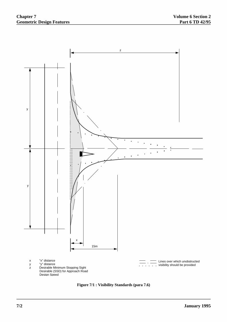
7.6 The principle of providing the requiredvisibility for drivers approaching the junction fromthe minor road has three distinct features.
a. Approaching drivers shall haveunobstructed visibility of the junction from adistance corresponding to the Desirable MinimumStopping Sight Distance (SSD) for the designspeed of the minor road, as described in TD 9(DMRB 6.1.1). This allows drivers time to slowdown safely at the junction, or stop, if this isnecessary. Where a "Give Way" sign is proposedthe visibility envelope shall be widened to includethe sign.
b. From a point 15m back along thecentreline of the minor road measured from thecontinuation of the line of the nearside edge of therunning carriageway of the major road (not fromthe continuation of the back of the major roadhardstrip if this is present), an approaching drivershall be able to see clearly the junction form, andthose peripheral elements of the junction layout.This provides the driver with an idea of thejunction form, possible movements and conflicts,and possible required action before reaching themajor road.
yd
o
FOR USE OUTSIDE THE AGENCY
ONIC DOCUMENT ARE UNCONTROLLED 7/1
Chapter 7 Volume 6 Section 2Geometric Design Features Part 6 TD 42/95
15m
x
y
y
z
x "x" distancey "y" distancez Desirable Minimum Stopping Sight Desirable (SSD) for Approach Road Design Speed
Lines over which unobstructedvisibility should be provided
Figure 7/1 : Visibility Standards (para 7.6)
ELECTRONIC COPY - NOT FOR USE OUTSIDE THE AGENCY
PAPER COPIES OF THIS ELECTRONIC DOCUMENT ARE UNCONTROLLED January 19957/2
Volume 6 Section 2 Chapter 7Part 6 TD 42/95 Geometric Design Features
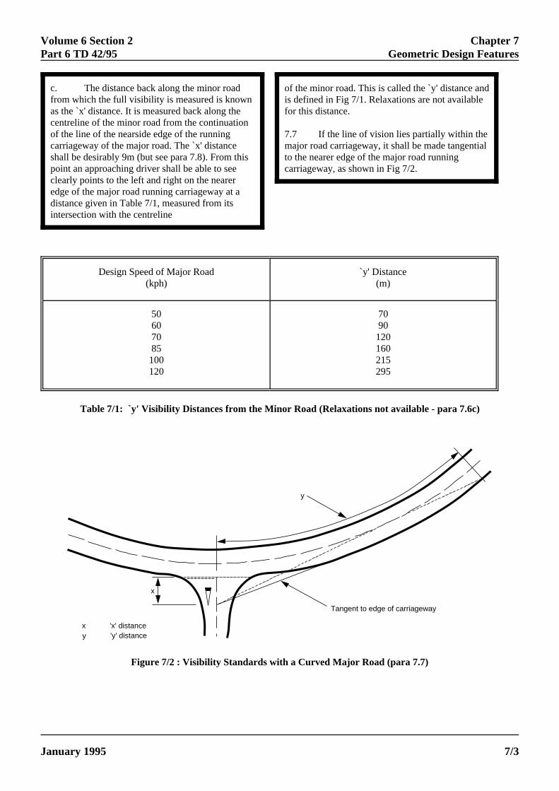
c. The distance back along the minor roadfrom which the full visibility is measured is knownas the `x' distance. It is measured back along thecentreline of the minor road from the continuationof the line of the nearside edge of the runningcarriageway of the major road. The `x' distanceshall be desirably 9m (but see para 7.8). From thispoint an approaching driver shall be able to seeclearly points to the left and right on the neareredge of the major road running carriageway at adistance given in Table 7/1, measured from itsintersection with the centreline
ELECTRONIC COPY - NO
January 1995 PAPER COPIES OF THIS ELECT
of the minor road. This is called the `y' distance andis defined in Fig 7/1. Relaxations are not availablefor this distance.
7.7 If the line of vision lies partially within themajor road carriageway, it shall be made tangentialto the nearer edge of the major road runningcarriageway, as shown in Fig 7/2.
y
y
x
Tangent to edge of carriageway
x 'x' distance'y' distance
Design Speed of Major Road `y' Distance(kph) (m)
50 7060 9070 12085 160100 215120 295
Table 7/1: `y' Visibility Distances from the Minor Road (Relaxations not available - para 7.6c)
Figure 7/2 : Visibility Standards with a Curved Major Road (para 7.7)
T FOR USE OUTSIDE THE AGENCY
RONIC DOCUMENT ARE UNCONTROLLED 7/3
Chapter 7 Volume 6 Section 2Geometric Design Features Part 6 TD 42/95
sle
7.8 In difficult circumstances, the `x' distancemay be taken as a Relaxation from 9.0m to 4.5mfor lightly trafficked simple junctions, and inexceptionally difficult circumstances, to 2.4m backfrom the nearer edge of the major road runningcarriageway. The `x' distance, from which full `y'distance visibility is provided, shall not be morethan 9m, as this induces high minor road approachspeeds into the junction, and leads to excessiveland take.
7.9 Similarly, although the `y' distance shallalways be provided, there is little advantage inincreasing it, as this too can induce high approachspeeds and take the attention of the minor roaddriver away from the immediate junctionconditions. Increased visibility shall not beprovided to increase the capacities of variousturning movements.
7.10 These visibility standards apply to newjunctions and to improvements to existingjunctions.
7.11 Where the major road is a dualcarriageway with a central reserve of adequatewidth to shelter turning traffic, the standardvisibility splay to the left is not required, but thecentral reserve to the left of the minor road shall bekept clear of obstructions for the appropriate `y'distance, when viewed from an `x' distance of2.4m.
D
7trCmd
7.12 If the major road is one way, a single visibilitysplay in the direction of approaching traffic will suffice.If the minor road serves as a one way exit from themajor road, no visibility splays will be required,provided that forward visibility for turning vehicles isadequate.
7.13 Vehicles parked within splay lines mayobstruct visibility. Where necessary, parking and accessshould be controlled to prevent this. Care should also betaken in the placing of signs, landscaping and streetfurniture within the visibility splay areas to ensure that
7.1desdevwhvehexior lreqcomcasassjun
7.1a sthathismecoumaarevehby by othinsdiffare
Co
7.1vehcorare
ELECTRONIC COPY
PAPER COPIES OF THIS EL7/4
their obstructive effect is minimal.
esign Vehicle
.14 Allowance shall be made for the swepturning paths of long vehicles where they caneasonably be expected to use a junction.onsideration shall also be given to theanoeuvring characteristics of these vehicles in theesign of staggered junctions.
5 All of the geometric parameters used in theign of a major/minor priority junction have beeneloped to cater for a 16.5m long articulated vehicle,
ose turning width is greater than for most othericles within the normal dimensions permitted in the
sting Vehicle Construction and Use Regulations,ikely to be permitted in the near future. The turninguirements of an 18.35m long drawbar trailerbination are less onerous regarding road width. In
es where hardstrips are present, the design vehicle iumed to use these on some turns, and at some simpctions, it may encroach into opposing traffic lanes.
6 However, a 15.5m long articulated vehicle withingle rear axle has been shown to be more onerousn the 16.5m long vehicle, but the small numbers of type of vehicle currently operating in Great Britainan that designing all junctions for such vehiclesld be economically unjustifiable. Hence, if thejor/minor priority junction being designed is in ana where there is likely to be regular use by suchicles, the designer should take account of this either
amending the design to cater for such a vehicle, oraccepting that these vehicles may encroach intoer traffic lanes, or overrun other areas. In suchtances, consideration may be given to providingerential coloured or raised surfacing indicating thea of allowable overrun.
rner Radii
7 Where no provision is made for large goodsicles, it is recommended that the minimum circularner radius at simple junctions should be 6m in urbanas and 10m in rural areas. Where provision is to be
made for large goods vehicles, the recommendedcircular corner radius is:-
- NOT FOR USE OUTSIDE THE AGENCY
ECTRONIC DOCUMENT ARE UNCONTROLLED January 1995
Volume 6 Section 2 Chapter 7Part 6 TD 42/95 Geometric Design Features
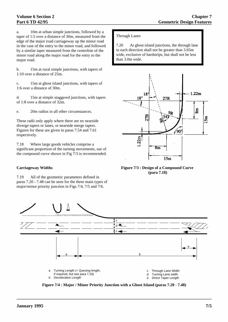
a. 10m at urban simple junctions, followed by ataper of 1:5 over a distance of 30m, measured from edge of the major road carriageway up the minor roain the case of the entry to the minor road, and followby a similar taper measured from the centreline of thminor road along the major road for the entry to themajor road.
b. 15m at rural simple junctions, with tapers of1:10 over a distance of 25m.
c. 15m at ghost island junctions, with tapers of1:6 over a distance of 30m.
d. 15m at simple staggered junctions, with tapeof 1:8 over a distance of 32m.
e. 20m radius in all other circumstances.
These radii only apply where there are no nearsidediverge tapers or lanes, or nearside merge tapers.Figures for these are given in paras 7.54 and 7.61respectively.
7.18 Where large goods vehicles comprise asignificant proportion of the turning movements, usethe compound curve shown in Fig 7/3 is recommend
Carriageway Widths
7.19 All of the geometric parameters defined in
ELECTRONIC COPY -
January 1995 PAPER COPIES OF THIS ELE
paras 7.20 - 7.48 can be seen for the three mai
Through Lanes
7.20 At ghost island junctions, the through lanein each direction shall not be greater than 3.65mwide, exclusive of hardstrips, but shall not be lessthan 3.0m wide.
thedede
rs
ofed.
Figure 7/3 : Design of a Compound Curve
n types of
(para 7.18)
major/minor priority junction in Figs 7/4, 7/5 and 7/6.
Figure 7/4 : Major / Minor Priority Junction with a Ghost Island (paras 7.20 - 7.48)
a b
c
d
c
e
a Turning Length (+ Queuing length, if required, but see para 7.33)b Deceleration Length
c Through Lane Widthd Turning Lane widthe Direct Taper Length
NOT FOR USE OUTSIDE THE AGENCY
CTRONIC DOCUMENT ARE UNCONTROLLED 7/5
Chapter 7 Volume 6 Section 2Geometric Design Features Part 6 TD 42/95
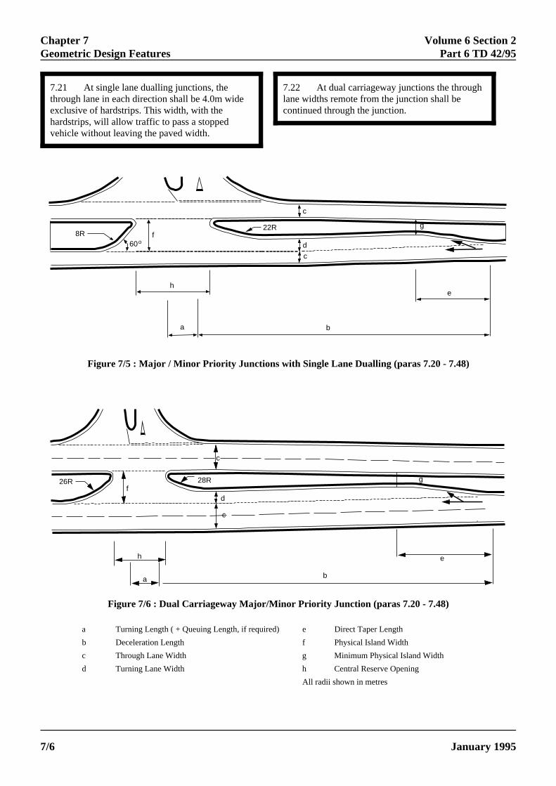
7.21 At single lane dualling junctions, thethrough lane in each direction shall be 4.0m wideexclusive of hardstrips. This width, with thehardstrips, will allow traffic to pass a stoppedvehicle without leaving the paved width.
7.22lane widcontinu
ELECTRONIC COPY - NOT
PAPER COPIES OF THIS ELECTRO7/6
At dual carriageway junctions the throughths remote from the junction shall be
ed through the junction.
8R60o
f22R
c
c
d
g
h
a b
e
26R 28R
c
fd
c
g
h
a b
e
Figure 7/5 : Major / Minor Priority Junctions with Single Lane Dualling (paras 7.20 - 7.48)
Figure 7/6 : Dual Carriageway Major/Minor Priority Junction (paras 7.20 - 7.48)
a Turning Length ( + Queuing Length, if required) e Direct Taper Length
b Deceleration Length f Physical Island Width
c Through Lane Width g Minimum Physical Island Width
d Turning Lane Width h Central Reserve Opening
All radii shown in metres
FOR USE OUTSIDE THE AGENCY
NIC DOCUMENT ARE UNCONTROLLED January 1995
Volume 6 Section 2 Chapter 7Part 6 TD 42/95 Geometric Design Features
Minor Road Approaches
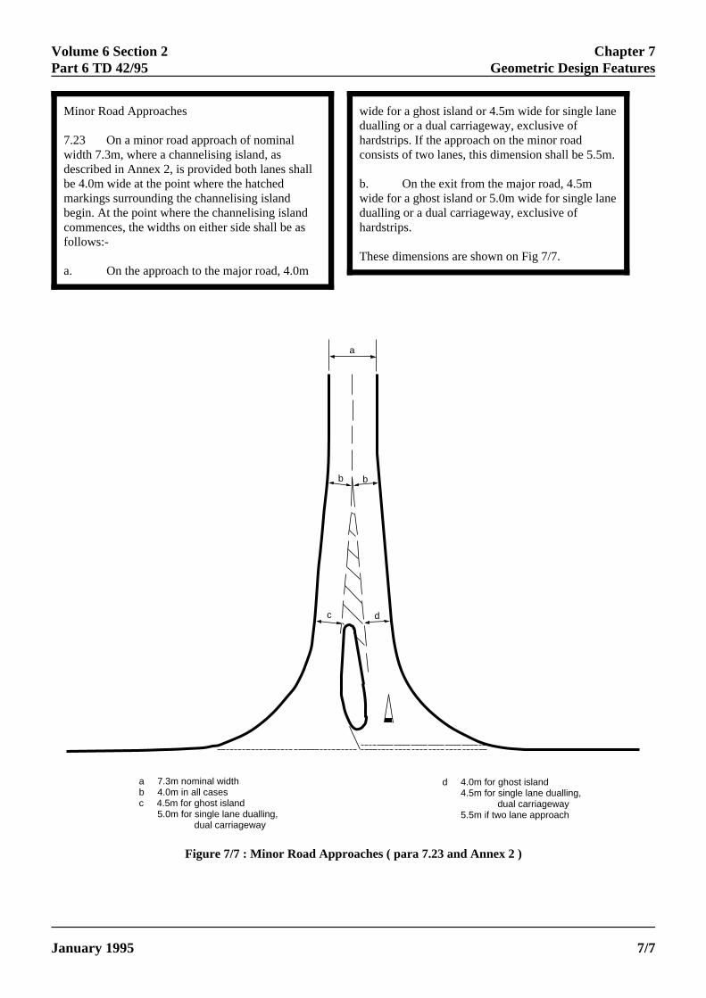
7.23 On a minor road approach of nominalwidth 7.3m, where a channelising island, asdescribed in Annex 2, is provided both lanes shallbe 4.0m wide at the point where the hatchedmarkings surrounding the channelising islandbegin. At the point where the channelising islandcommences, the widths on either side shall be asfollows:-
a. On the approach to the major road, 4.0m
ELECTRONIC COPY - NO
January 1995 PAPER COPIES OF THIS ELECT
wide for a ghost island or 4.5m wide for single lanedualling or a dual carriageway, exclusive ofhardstrips. If the approach on the minor roadconsists of two lanes, this dimension shall be 5.5m.
b. On the exit from the major road, 4.5mwide for a ghost island or 5.0m wide for single lanedualling or a dual carriageway, exclusive ofhardstrips.
These dimensions are shown on Fig 7/7.
a
b b
c d
a 7.3m nominal widthb 4.0m in all casesc 4.5m for ghost island 5.0m for single lane dualling, dual carriageway
d 4.0m for ghost island 4.5m for single lane dualling, dual carriageway 5.5m if two lane approach
Figure 7/7 : Minor Road Approaches ( para 7.23 and Annex 2 )
T FOR USE OUTSIDE THE AGENCY
RONIC DOCUMENT ARE UNCONTROLLED 7/7
Chapter 7 Volume 6 Section 2Geometric Design Features Part 6 TD 42/95
theh antion.sed.
t
an
of
the
Carriageway Widths around Curves
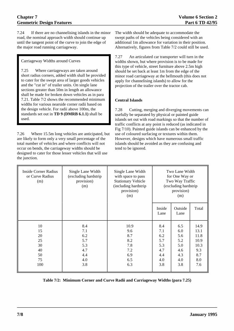
7.25 Where carriageways are taken aroundshort radius corners, added width shall be provideto cater for the swept area of larger goods vehicleand the "cut in" of trailer units. On single lanesections greater than 50m in length an allowanceshall be made for broken down vehicles as in para7.21. Table 7/2 shows the recommended minimumwidths for various nearside corner radii based onthe design vehicle. For radii above 100m, thestandards set out in TD 9 (DMRB 6.1.1) shall beused.
7.24 If there are no channelising islands in the mroad, the nominal approach width should continue uuntil the tangent point of the curve to join the edge othe major road running carriageway.
7.26 Where 15.5m long vehicles are anticipated,are likely to form only a very small percentage of thetotal number of vehicles and where conflicts will notoccur on bends, the carriageway widths should bedesigned to cater for those lesser vehicles that will u
ELECTRONIC COPY - NOT
PAPER COPIES OF THIS ELECTR7/8
the junction.
ds
inor The width should be adequate to accommodate p swept paths of the vehicles being considered witf additional 1m allowance for variation in their posi
Alternatively, figures from Table 7/2 could still be u
but
se
7.27 An articulated car transporter will turn in thewidths shown, but where provision is to be made forthis type of vehicle, street furniture above 2.5m highshould be set back at least 1m from the edge of theminor road carriageway at the bellmouth (this does noapply for channelising islands) to allow for theprojection of the trailer over the tractor cab.
Central Islands
7.28 Cutting, merging and diverging movements cusefully be separated by physical or painted guideislands set out with road markings so that the numbertraffic conflicts at any point is reduced (as indicated inFig 7/10). Painted guide islands can be enhanced by use of coloured surfacing or textures within them.However, designs which have numerous small trafficislands should be avoided as they are confusing andtend to be ignored.
Inside Corner Radius Single Lane Width Single Lane Width Two Lane Widthor Curve Radius (excluding hardstrip with space to pass for One Way or
(m) provision) Stationary Vehicle Two Way Traffic(m) (including hardstrip (excluding hardstrip
provision) provision)(m) (m)
Inside Outside TotalLane Lane
10 8.4 10.9 8.4 6.5 14.915 7.1 9.6 7.1 6.0 13.120 6.2 8.7 6.2 5.6 11.825 5.7 8.2 5.7 5.2 10.930 5.3 7.8 5.3 5.0 10.340 4.7 7.2 4.7 4.6 9.350 4.4 6.9 4.4 4.3 8.775 4.0 6.5 4.0 4.0 8.0100 3.8 6.3 3.8 3.8 7.6
Table 7/2: Minimum Corner and Curve Radii and Carriageway Widths (para 7.25)
FOR USE OUTSIDE THE AGENCY
ONIC DOCUMENT ARE UNCONTROLLED January 1995
Volume 6 Section 2 Chapter 7Part 6 TD 42/95 Geometric Design Features
ere issign onrunning
ne
(as
toryehere, which
1
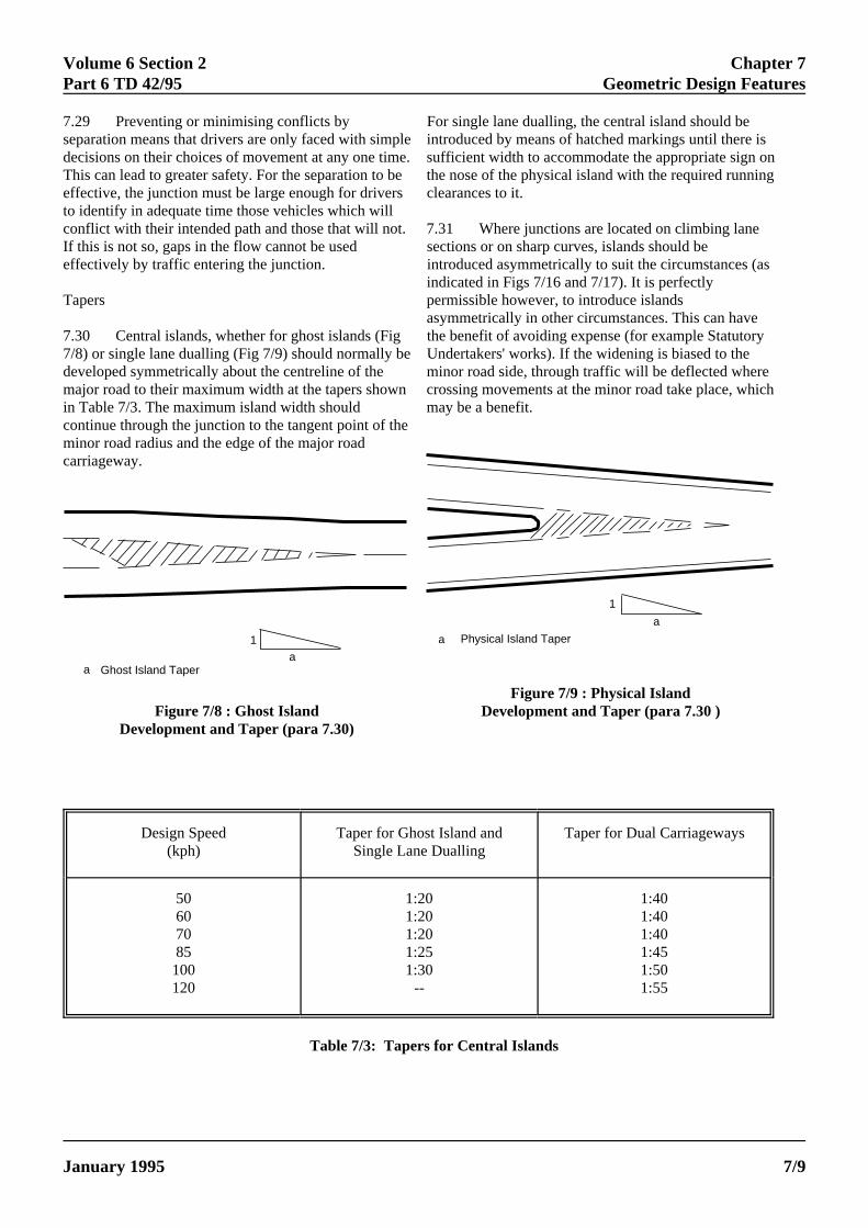
aa Ghost Island Taper
7.29 Preventing or minimising conflicts byseparation means that drivers are only faced with sidecisions on their choices of movement at any one This can lead to greater safety. For the separation teffective, the junction must be large enough for drivto identify in adequate time those vehicles which wiconflict with their intended path and those that will nIf this is not so, gaps in the flow cannot be usedeffectively by traffic entering the junction.
Tapers
7.30 Central islands, whether for ghost islands (F7/8) or single lane dualling (Fig 7/9) should normallydeveloped symmetrically about the centreline of themajor road to their maximum width at the tapers shoin Table 7/3. The maximum island width shouldcontinue through the junction to the tangent point ofminor road radius and the edge of the major roadcarriageway.
Figure 7/8 : Ghost IslandDevelopment and Taper (para 7.30)
ELECTRONIC COPY - NO
January 1995 PAPER COPIES OF THIS ELECT
1
a
a Physical Island Taper
For single lane dualling, the central island should bemple introduced by means of hatched markings until thtime. sufficient width to accommodate the appropriate o be the nose of the physical island with the required ers clearances to it. llot. 7.31 Where junctions are located on climbing la
sections or on sharp curves, islands should beintroduced asymmetrically to suit the circumstances
permissible however, to introduce islands
ig the benefit of avoiding expense (for example Statu be Undertakers' works). If the widening is biased to th
minor road side, through traffic will be deflected wwn crossing movements at the minor road take place
may be a benefit. the
indicated in Figs 7/16 and 7/17). It is perfectly
asymmetrically in other circumstances. This can have
Figure 7/9 : Physical IslandDevelopment and Taper (para 7.30 )
Design Speed Taper for Ghost Island and Taper for Dual Carriageways(kph) Single Lane Dualling
50 1:20 1:4060 1:20 1:4070 1:20 1:4085 1:25 1:45100 1:30 1:50120 -- 1:55
Table 7/3: Tapers for Central Islands
T FOR USE OUTSIDE THE AGENCY
RONIC DOCUMENT ARE UNCONTROLLED 7/9
Chapter 7 Volume 6 Section 2Geometric Design Features Part 6 TD 42/95
eg
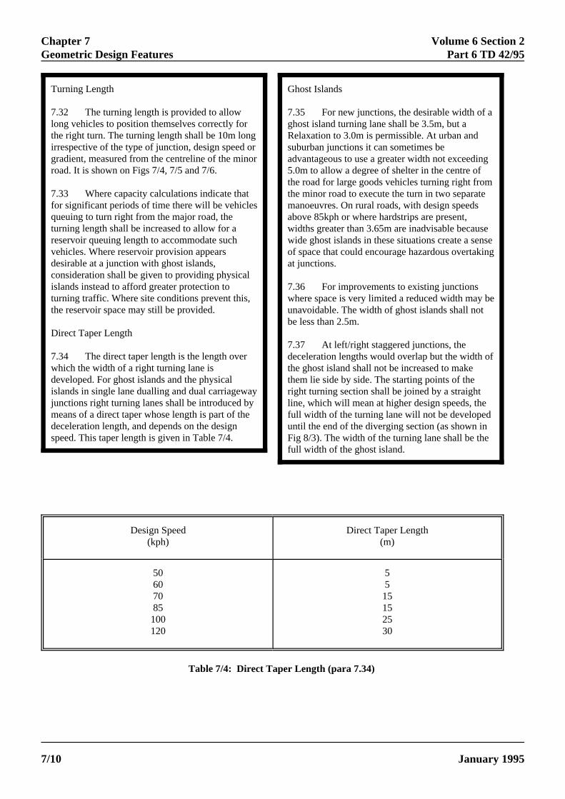
Turning Length
7.32 The turning length is provided to allowlong vehicles to position themselves correctly forthe right turn. The turning length shall be 10m longirrespective of the type of junction, design speed orgradient, measured from the centreline of the minorroad. It is shown on Figs 7/4, 7/5 and 7/6.
7.33 Where capacity calculations indicate thatfor significant periods of time there will be vehiclesqueuing to turn right from the major road, theturning length shall be increased to allow for areservoir queuing length to accommodate suchvehicles. Where reservoir provision appearsdesirable at a junction with ghost islands,consideration shall be given to providing physicalislands instead to afford greater protection toturning traffic. Where site conditions prevent this,the reservoir space may still be provided.
Direct Taper Length
7.34 The direct taper length is the length overwhich the width of a right turning lane isdeveloped. For ghost islands and the physicalislands in single lane dualling and dual carriagewayjunctions right turning lanes shall be introduced bymeans of a direct taper whose length is part of thedeceleration length, and depends on the designspeed. This taper length is given in Table 7/4.
ELECTRONIC COPY - NOT
PAPER COPIES OF THIS ELECTR7/10
Ghost Islands
7.35 For new junctions, the desirable width of aghost island turning lane shall be 3.5m, but aRelaxation to 3.0m is permissible. At urban andsuburban junctions it can sometimes beadvantageous to use a greater width not exceeding5.0m to allow a degree of shelter in the centre ofthe road for large goods vehicles turning right fromthe minor road to execute the turn in two separatemanoeuvres. On rural roads, with design speedsabove 85kph or where hardstrips are present,widths greater than 3.65m are inadvisable becausewide ghost islands in these situations create a sensof space that could encourage hazardous overtakinat junctions.
7.36 For improvements to existing junctionswhere space is very limited a reduced width may beunavoidable. The width of ghost islands shall notbe less than 2.5m.
7.37 At left/right staggered junctions, thedeceleration lengths would overlap but the width ofthe ghost island shall not be increased to makethem lie side by side. The starting points of theright turning section shall be joined by a straightline, which will mean at higher design speeds, thefull width of the turning lane will not be developeduntil the end of the diverging section (as shown inFig 8/3). The width of the turning lane shall be thefull width of the ghost island.
Design Speed Direct Taper Length(kph) (m)
50 560 570 1585 15100 25120 30
Table 7/4: Direct Taper Length (para 7.34)
FOR USE OUTSIDE THE AGENCY
ONIC DOCUMENT ARE UNCONTROLLED January 1995
Volume 6 Section 2 Chapter 7Part 6 TD 42/95 res
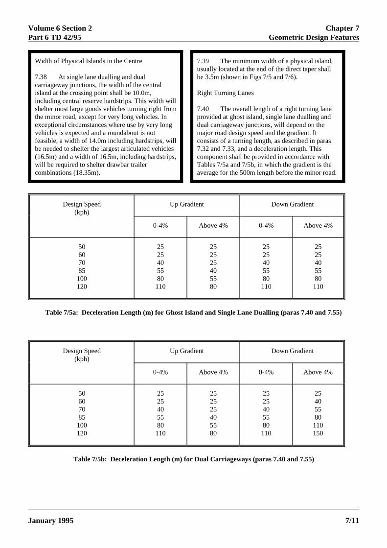
Width of Physical Islands in the Centre
7.38 At single lane dualling and dualcarriageway junctions, the width of the centralisland at the crossing point shall be 10.0m,including central reserve hardstrips. This width willshelter most large goods vehicles turning right fromthe minor road, except for very long vehicles. Inexceptional circumstances where use by very longvehicles is expected and a roundabout is notfeasible, a width of 14.0m including hardstrips, willbe needed to shelter the largest articulated vehicles(16.5m) and a width of 16.5m, including hardstrips,will be required to shelter drawbar trailercombinations (18.35m).
ELECTRONIC COPY -
January 1995 PAPER COPIES OF THIS ELE
Geometric Design Featu
7.39 The minimum width of a physical island,usually located at the end of the direct taper shallbe 3.5m (shown in Figs 7/5 and 7/6).
Right Turning Lanes
7.40 The overall length of a right turning laneprovided at ghost island, single lane dualling anddual carriageway junctions, will depend on themajor road design speed and the gradient. Itconsists of a turning length, as described in paras7.32 and 7.33, and a deceleration length. Thiscomponent shall be provided in accordance withTables 7/5a and 7/5b, in which the gradient is theaverage for the 500m length before the minor road.
)
Design Speed Up Gradient Down Gradient(kph)
0-4% Above 4% 0-4% Above 4%
50 25 25 25 2560 25 25 25 2570 40 25 40 4085 55 40 55 55100 80 55 80 80120 110 80 110 110
Table 7/5a: Deceleration Length (m) for Ghost Island and Single Lane Dualling (paras 7.40 and 7.55
Design Speed Up Gradient Down Gradient(kph)
0-4% Above 4% 0-4% Above 4%
50 25 25 25 2560 25 25 25 4070 40 25 40 5585 55 40 55 80100 80 55 80 110120 110 80 110 150
Table 7/5b: Deceleration Length (m) for Dual Carriageways (paras 7.40 and 7.55)
NOT FOR USE OUTSIDE THE AGENCY
CTRONIC DOCUMENT ARE UNCONTROLLED 7/11
Chapter 7 Volume 6 Section 2Geometric Design Features Part 6 TD 42/95
seedate theles.
be
ic
nction
rry out
th
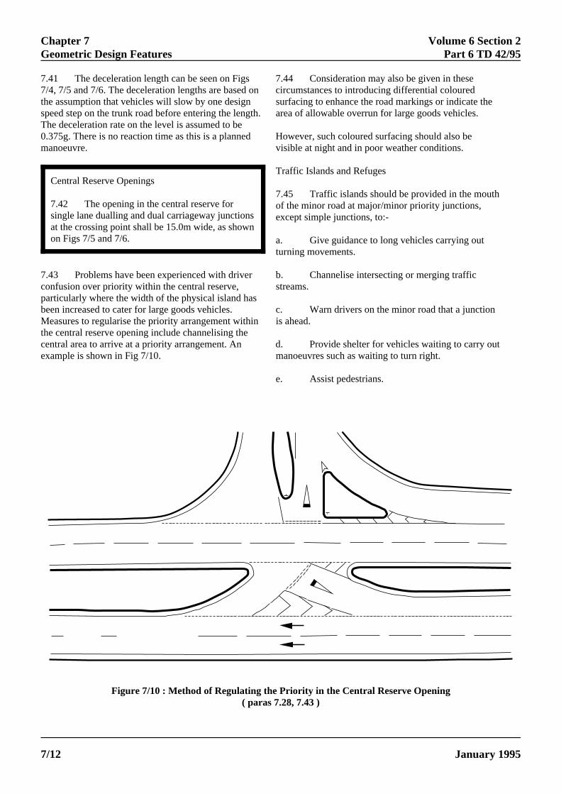
Central Reserve Openings7.42 The opening in the central reserve forsingle lane dualling and dual carriageway junctionsat the crossing point shall be 15.0m wide, as showon Figs 7/5 and 7/6.
7.41 The deceleration length can be seen on Figs7/4, 7/5 and 7/6. The deceleration lengths are basedthe assumption that vehicles will slow by one designspeed step on the trunk road before entering the lenThe deceleration rate on the level is assumed to be0.375g. There is no reaction time as this is a plannedmanoeuvre.
7.43 Problems have been experienced with driveconfusion over priority within the central reserve,particularly where the width of the physical island habeen increased to cater for large goods vehicles.Measures to regularise the priority arrangement withthe central reserve opening include channelising thecentral area to arrive at a priority arrangement. An example is shown in Fig 7/10.
ELECTRONIC COPY - N
PAPER COPIES OF THIS ELEC7/12
n
7.44 Consideration may also be given in the on circumstances to introducing differential colour
surfacing to enhance the road markings or indicgth. area of allowable overrun for large goods vehic
However, such coloured surfacing should also visible at night and in poor weather conditions.
r b. Channelise intersecting or merging traffstreams.
sc. Warn drivers on the minor road that a ju
in is ahead.
d. Provide shelter for vehicles waiting to camanoeuvres such as waiting to turn right.
Traffic Islands and Refuges
7.45 Traffic islands should be provided in the mouof the minor road at major/minor priority junctions,except simple junctions, to:-
a. Give guidance to long vehicles carrying outturning movements.
e. Assist pedestrians.
Figure 7/10 : Method of Regulating the Priority in the Central Reserve Opening( paras 7.28, 7.43 )
OT FOR USE OUTSIDE THE AGENCY
TRONIC DOCUMENT ARE UNCONTROLLED January 1995
Volume 6 Section 2 Chapter 7Part 6 TD 42/95 Geometric Design Features
7.46 Physical islands shall have an area of atleast 4.5 square metres, and shall be treated to beconspicuous in poor lighting conditions. Smallerareas should be defined by road markings. The riskof overriding the islands can be reduced byoffsetting the approach nose from the edge of thevehicle paths.
7.47 Where a traffic island serves as a refugefor pedestrians it shall be at least 1.5m wide andhave openings in the centre at carriageway level tomake the crossing easier for pedestrians (see Fig5/2). Opposite the refuge openings, dropped kerbsshall be installed for the same reason. A refugebeacon about 4-5m high may be placed between thebollards. Care shall be taken that street furnituredoes not obstruct the drivers' view of pedestrians.
7.48 The recommended layout and details of thedesign of rural channelising islands can be found inAnnex 2.
Diverging Tapers and Lanes
7.49 Major road traffic, when slowing down on theapproach to a junction in order to turn into a minorroad, may impede the following vehicles that are notturning. It is helpful therefore to permit the divergenceof the two streams at a small angle and approximatelyequal speed by the provision of a diverging taper.
7.50 Right turning tapers and lanes in the centre ofghost islands and single lane dualling on singlecarriageways, and on dual carriageways are especialluseful as they provide a convenient space for vehiclesslow down and wait before turning off the major road,and assist the right turn out of the minor road. Details the design of such facilities are covered in para 7.40.
7.51 Nearside diverging tapers allow left turningmajor road traffic to slow down and leave the majorroad without impeding the following through traffic, buthey are of less benefit in terms of operation and safetthan right turning lanes, possibly because the left turnfrom the major road does not cross an opposing trafficstream and is rarely impeded. However, nearsidediverging tapers should always be considered for highspeed roads or on gradients.
ELECTRONIC COPY - NOT
January 1995 PAPER COPIES OF THIS ELECTRO
7.52 Nearside diverging tapers shall not beprovided at simple junctions (para 1.14). They shallbe provided at junctions between "A" and "B"roads where the design speed for the A road is85kph or above. They shall be provided at otherjunctions in the following circumstances for trafficin the design year:-
a. Where the volume of left turning traffic isgreater than 600 vehicles AADT.
b. Where the percentage of large goodsvehicles is greater than 20%, and the volume of leftturning traffic is greater than 450 vehicles AADT.
c. Where the junction is on an up or downgradient of greater than 4% at any design speed andthe volume of left turning traffic is greater than 450vehicles AADT.
Where the major road flow is greater than 7000 -8000 AADT then the above figures for turningtraffic can be halved. At some junctions there maybe safety benefits in providing nearside divergingtapers at lower flows.
7.53 They shall not be provided where theminor road is on the inside of a curve where trafficon the diverging lane could adversely affectvisibility for drivers emerging from the minor road.They shall generally not be provided where thedesign speed for the major road is less than 85kphnor where the cost of provision is excessive. In thatcase adequate warning of the junction ahead mustbe provided.
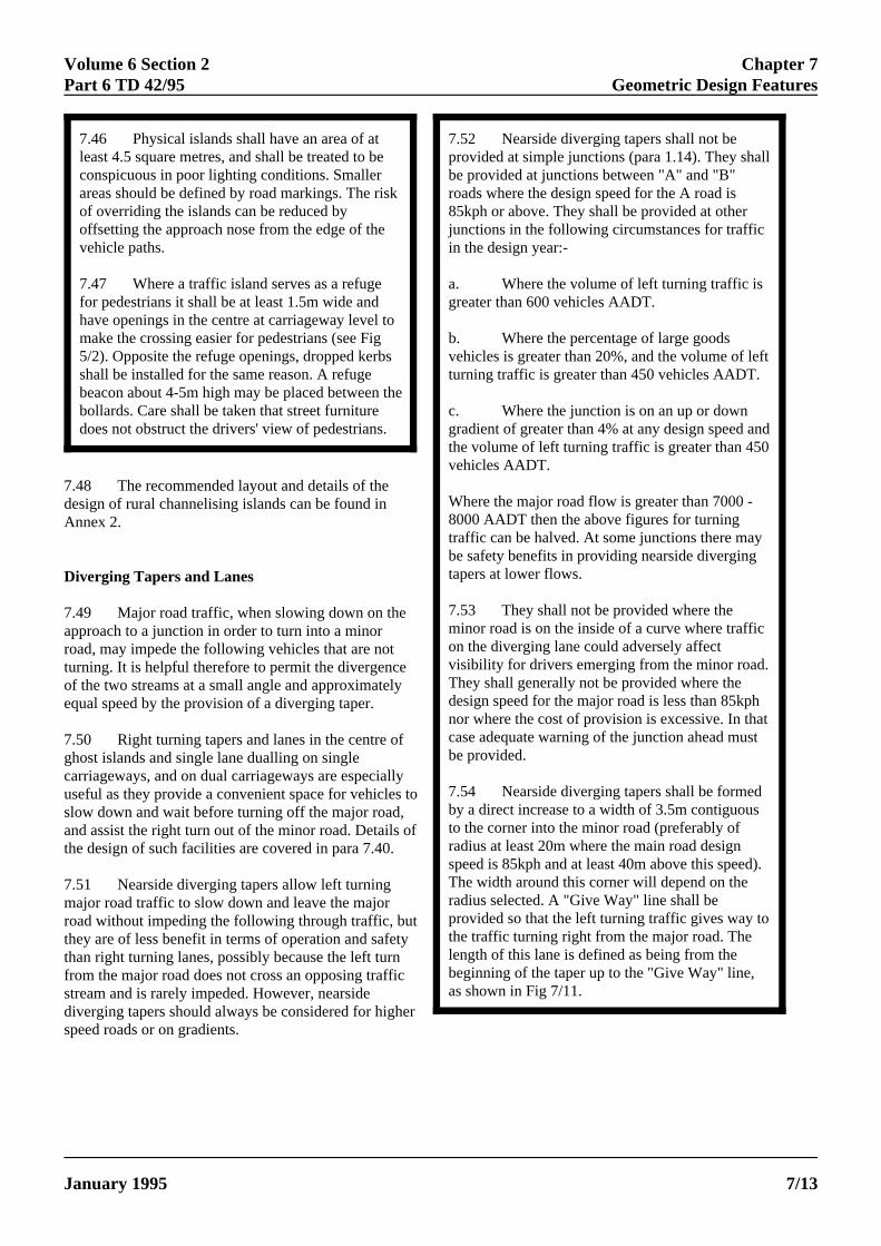
7.54 Nearside diverging tapers shall be formedby a direct increase to a width of 3.5m contiguousto the corner into the minor road (preferably ofradius at least 20m where the main road designspeed is 85kph and at least 40m above this speed).The width around this corner will depend on theradius selected. A "Give Way" line shall beprovided so that the left turning traffic gives way tothe traffic turning right from the major road. Thelength of this lane is defined as being from thebeginning of the taper up to the "Give Way" line,as shown in Fig 7/11.
y to
of
ty
er
FOR USE OUTSIDE THE AGENCY
NIC DOCUMENT ARE UNCONTROLLED 7/13
Chapter 7 Volume 6 Section 2Geometric Design Features Part 6 TD 42/95
a
a Deceleration Length
Figure 7/11 : Major / Minor Priority Junctions with Nearside Diverging Taper ( para 7.54 )
7.55 The desirable length of a nearsidediverging taper shall be that of the relevantdeceleration length given in Tables 7/5a and 7/5b.Where there are severe site constraints this may bereduced by half as a Relaxation where the designspeed is 85kph, but then a lane shall be at least 35mlong.
7AathtathInpfo
ELECTRONIC COPY - N
PAPER COPIES OF THIS ELEC7/14
.56 At higher major road flows over 7000 - 8000ADT, vehicles decelerating on the main carriagewaynd moving into the diverging taper to a point whereere is a full lane width available in the divergingper, may have a significant effect on the capacity ofe through carriageway by impeding following drivers. this instance, consideration should be given to the
rovision of a nearside auxiliary lane instead of a taperr diverging traffic. The provision of an auxiliary lane,
as shown in Fig 7/12, would allow turning traffic tomove off the mainline prior to any deceleration.
a
b
a Deceleration Lengthb Direct Taper Length
Figure 7/12 : Major/Minor Priority Junction with Nearside Auxiliary Lane (para 7.56)
OT FOR USE OUTSIDE THE AGENCY
TRONIC DOCUMENT ARE UNCONTROLLED January 1995
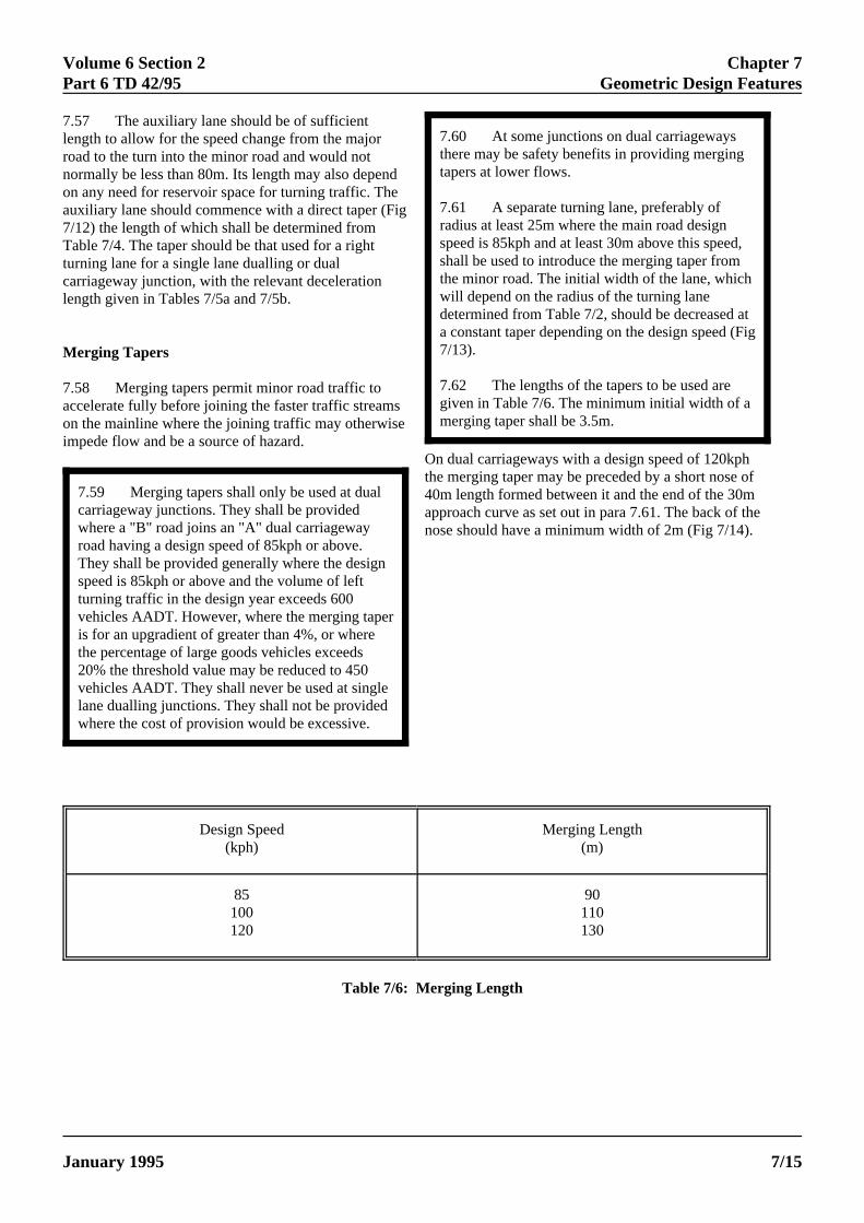
Volume 6 Section 2 Chapter 7Part 6 TD 42/95 Geometric Design Features
7.59 Merging tapers shall only be used at dualcarriageway junctions. They shall be providedwhere a "B" road joins an "A" dual carriagewayroad having a design speed of 85kph or above.They shall be provided generally where the designspeed is 85kph or above and the volume of leftturning traffic in the design year exceeds 600vehicles AADT. However, where the merging taperis for an upgradient of greater than 4%, or wherethe percentage of large goods vehicles exceeds20% the threshold value may be reduced to 450vehicles AADT. They shall never be used at singlelane dualling junctions. They shall not be providedwhere the cost of provision would be excessive.
7.57 The auxiliary lane should be of sufficientlength to allow for the speed change from the majorroad to the turn into the minor road and would notnormally be less than 80m. Its length may also depenon any need for reservoir space for turning traffic. Thauxiliary lane should commence with a direct taper (F7/12) the length of which shall be determined fromTable 7/4. The taper should be that used for a rightturning lane for a single lane dualling or dualcarriageway junction, with the relevant decelerationlength given in Tables 7/5a and 7/5b.
Merging Tapers
7.58 Merging tapers permit minor road traffic toaccelerate fully before joining the faster traffic streamon the mainline where the joining traffic may otherwisimpede flow and be a source of hazard.
ELECTRONIC COPY
January 1995 PAPER COPIES OF THIS EL
7.60 At some junctions on dual carriagewaysthere may be safety benefits in providing mergingtapers at lower flows.
7.61 A separate turning lane, preferably ofradius at least 25m where the main road designspeed is 85kph and at least 30m above this speed,shall be used to introduce the merging taper fromthe minor road. The initial width of the lane, whichwill depend on the radius of the turning lanedetermined from Table 7/2, should be decreased ata constant taper depending on the design speed (Fig7/13).
7.62 The lengths of the tapers to be used aregiven in Table 7/6. The minimum initial width of amerging taper shall be 3.5m.
deig
se
On dual carriageways with a design speed of 120kphthe merging taper may be preceded by a short nose of40m length formed between it and the end of the 30mapproach curve as set out in para 7.61. The back of thenose should have a minimum width of 2m (Fig 7/14).
Design Speed Merging Length(kph) (m)
85 90100 110120 130
Table 7/6: Merging Length
- NOT FOR USE OUTSIDE THE AGENCY
ECTRONIC DOCUMENT ARE UNCONTROLLED 7/15
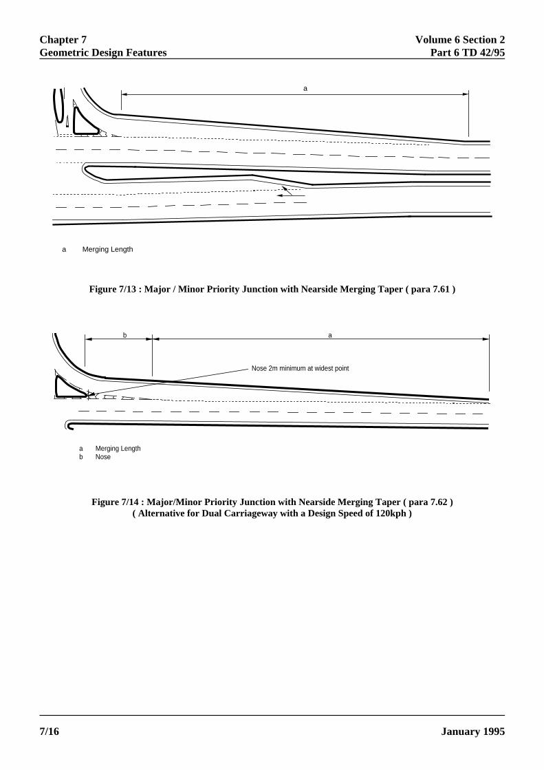
Chapter 7 Volume 6 Section 2Geometric Design Features Part 6 TD 42/95
a
a Merging Length
b a
Nose 2m minimum at widest point
a Merging Lengthb Nose
Figure 7/13 : Major / Minor Priority Junction with Nearside Merging Taper ( para 7.61 )
Figure 7/14 : Major/Minor Priority Junction with Nearside Merging Taper ( para 7.62 )( Alternative for Dual Carriageway with a Design Speed of 120kph )
ELECTRONIC COPY - NOT FOR USE OUTSIDE THE AGENCY
PAPER COPIES OF THIS ELECTRONIC DOCUMENT ARE UNCONTROLLED January 19957/16
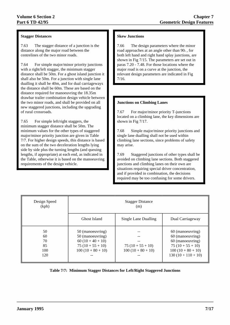
Volume 6 Section 2 Chapter 7Part 6 TD 42/95 Geometric Design Features
e
Stagger Distances
7.63 The stagger distance of a junction is thedistance along the major road between thecentrelines of the two minor roads.
7.64 For simple major/minor priority junctionswith a right/left stagger, the minimum staggerdistance shall be 50m. For a ghost island junction itshall also be 50m. For a junction with single lanedualling it shall be 40m, and for dual carriagewaysthe distance shall be 60m. These are based on thedistance required for manoeuvring the 18.35mdrawbar trailer combination design vehicle betweenthe two minor roads, and shall be provided on allnew staggered junctions, including the upgradingof rural crossroads.
7.65 For simple left/right staggers, theminimum stagger distance shall be 50m. Theminimum values for the other types of staggeredmajor/minor priority junction are given in Table7/7. For higher design speeds, this distance is baseon the sum of the two deceleration lengths lyingside by side plus the turning lengths (and queuinglengths, if appropriate) at each end, as indicated inthe Table, otherwise it is based on the manoeuvringrequirements of the design vehicle.
ELECTRONIC COPY - NOT
January 1995 PAPER COPIES OF THIS ELECTRO
d
Skew Junctions
7.66 The design parameters where the minorroad approaches at an angle other than 90E, forboth left hand and right hand splay junctions, areshown in Fig 7/15. The parameters are set out inparas 7.20 - 7.48. For those locations where themajor road is on a curve at the junction, therelevant design parameters are indicated in Fig7/16.
Junctions on Climbing Lanes
7.67 For major/minor priority T-junctionslocated on a climbing lane, the key dimensions areshown in Fig 7/17.
7.68 Simple major/minor priority junctions andsingle lane dualling shall not be used withinclimbing lane sections, since problems of safetymay arise.
7.69 Staggered junctions of other types shall bavoided on climbing lane sections. Both staggeredjunctions and climbing lanes on their own aresituations requiring special driver concentration,and if provided in combination, the decisionsrequired may be too confusing for some drivers.
Design Speed Stagger Distance(kph) (m)
Ghost Island Single Lane Dualling Dual Carriageway
50 50 (manoeuvring) -- 60 (manoeuvring)60 50 (manoeuvring) -- 60 (manoeuvring)70 60 (10 + 40 + 10) -- 60 (manoeuvring)85 75 (10 + 55 + 10) 75 (10 + 55 + 10) 75 (10 + 55 + 10)100 100 (10 + 80 + 10) 100 (10 + 80 + 10) 100 (10 + 80 + 10)120 -- -- 130 (10 + 110 + 10)
Table 7/7: Minimum Stagger Distances for Left/Right Staggered Junctions
FOR USE OUTSIDE THE AGENCY
NIC DOCUMENT ARE UNCONTROLLED 7/17
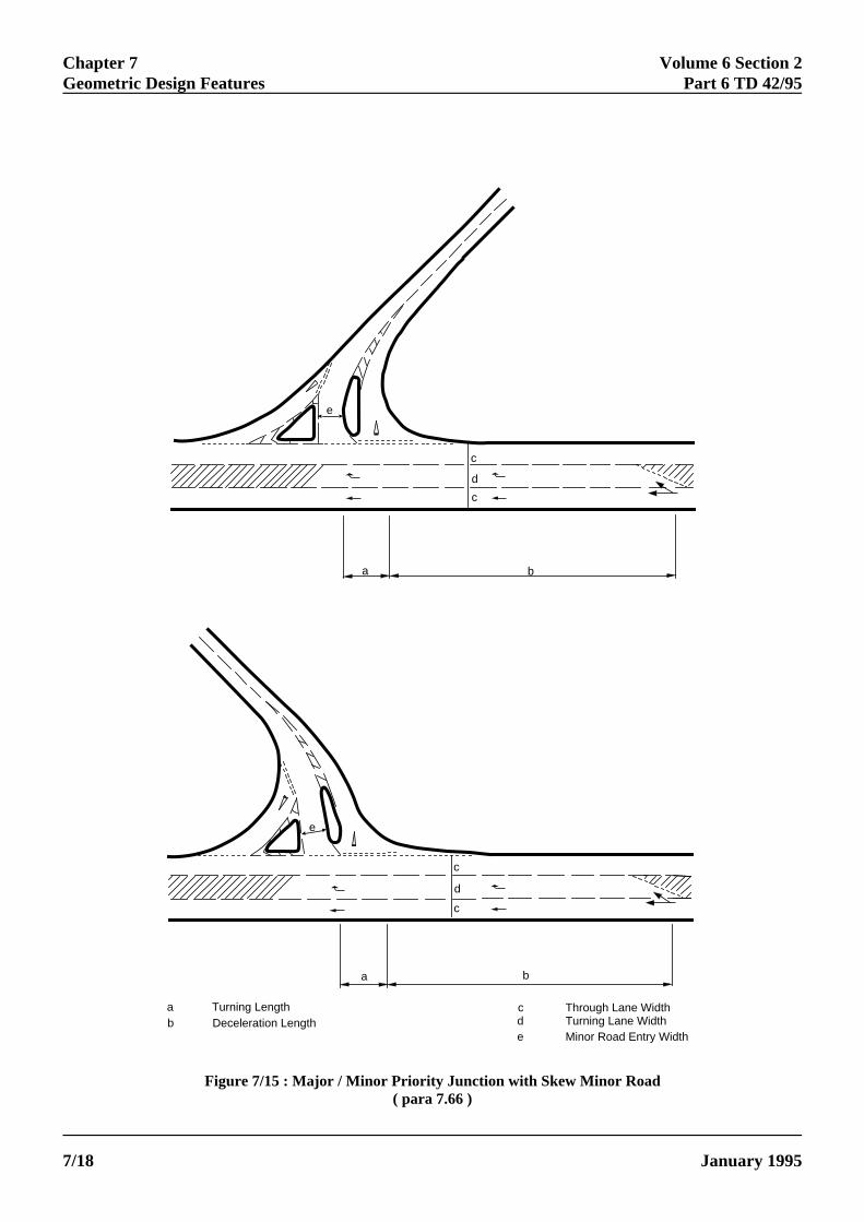
Chapter 7 Volume 6 Section 2Geometric Design Features Part 6 TD 42/95
c
e
c
c
d
a b
e
c
d
a b
a Turning Lengthb Deceleration Length
c Through Lane Widthd Turning Lane Widthe Minor Road Entry Width
Figure 7/15 : Major / Minor Priority Junction with Skew Minor Road( para 7.66 )
ELECTRONIC COPY - NOT FOR USE OUTSIDE THE AGENCY
PAPER COPIES OF THIS ELECTRONIC DOCUMENT ARE UNCONTROLLED January 19957/18
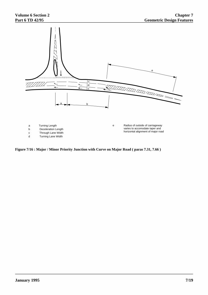
Volume 6 Section 2 Chapter 7Part 6 TD 42/95 Geometric Design Features
e
a b
c
cd
a Turning Lengthb Deceleration Lengthc Through Lane Widthd Turning Lane Width
e Radius of outside of carriageway varies to accomodate taper and horizontal alignment of major road
Figure 7/16 : Major / Minor Priority Junction with Curve on Major Road ( paras 7.31, 7.66 )
ELECTRONIC COPY - NOT FOR USE OUTSIDE THE AGENCY
January 1995 PAPER COPIES OF THIS ELECTRONIC DOCUMENT ARE UNCONTROLLED 7/19
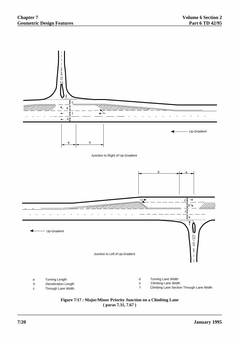
Chapter 7 Volume 6 Section 2Geometric Design Features Part 6 TD 42/95
7/2
c
d
f
e
a b
Up-Gradient
Junction to Right of Up-Gradient
b a
c
d
f
e
Up-Gradient
Junction to Left of Up-Gradient
d Turning Lane Widthe Climbing Lane Widthf Climbing Lane Section Through Lane Width
a Turning Lengthb Deceleration Lengthc Through Lane Width
Figure 7/17 : Major/Minor Priority Junction on a Climbing Lane( paras 7.31, 7.67 )
ELECTRONIC COPY - NOT FOR USE OUTSIDE THE AGENCY
PAPER COPIES OF THIS ELECTRONIC DOCUMENT ARE UNCONTROLLED January 19950
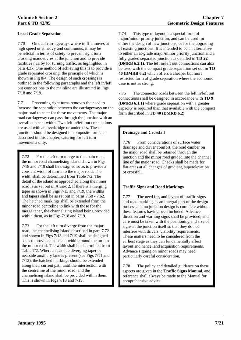
Volume 6 Section 2 Chapter 7Part 6 TD 42/95 Geometric Design Features
7.72 For the left turn merge to the main road,the minor road channelising island shown in Figs7/18 and 7/19 shall be designed so as to provide aconstant width of turn into the major road. Thewidth shall be determined from Table 7/2. Thedetail of the island as approached along the minorroad is as set out in Annex 2. If there is a mergingtaper as shown in Figs 7/13 and 7/19, the widthsand tapers shall be as set out in paras 7.58 - 7.62.The hatched markings shall be extended from theminor road centreline to link with those for themerge taper, the channelising island being providedwithin them, as in Figs 7/18 and 7/19.
7.73 For the left turn diverge from the majorroad, the channelising island described in para 7.72and shown in Figs 7/18 and 7/19 shall be designedso as to provide a constant width around the turn tothe minor road. The width shall be determined fromTable 7/2. Where a nearside diverging taper ornearside auxiliary lane is present (see Figs 7/11 and7/12), the hatched markings should be extendedalong their current path until the intersection withthe centreline of the minor road, and thechannelising island shall be provided within them.This is shown in Figs 7/18 and 7/19.
Local Grade Separation
7.70 On dual carriageways where traffic moves athigh speed or is heavy and continuous, it may bebeneficial in terms of safety to prevent right turncrossing manoeuvres at the junction and to providefacilities nearby for turning traffic, as highlighted inpara 4.3k. One method of achieving this is to provide grade separated crossing, the principle of which isshown in Fig 8/4. The design of such crossings isoutlined in the following paragraphs and the left in/leftout connections to the mainline are illustrated in Figs7/18 and 7/19.
7.71 Preventing right turns removes the need toincrease the separation between the carriageways onmajor road to cater for these movements. The majorroad carriageway can pass through the junction with aoverall constant width. Two left in/left out connectionsare used with an overbridge or underpass. Thesejunctions should be designed in composite form, asdescribed in this chapter, catering for left turnmovements only.
7meotf(b4rc
7c(cf
ELECTRONIC COPY - N
January 1995 PAPER COPIES OF THIS ELEC
Drainage and Crossfall
7.76 From considerations of surface waterdrainage and driver comfort, the road camber onthe major road shall be retained through thejunction and the minor road graded into the channelline of the major road. Checks shall be made forflat areas at all changes of gradient, superelevationor crossfall.
Traffic Signs and Road Markings
7.77 The need for, and layout of, traffic signsand road markings is an integral part of the designprocess and no junction design is complete withoutthese features having been included. Advancedirection and warning signs shall be provided, andcare must be taken with the positioning and size ofsigns at the junction itself so that they do notinterfere with drivers' visibility requirements.These matters need to be considered from theearliest stage as they can fundamentally affectlayout and hence land acquisition requirements.Advance signing on minor roads may needparticularly careful consideration.
7.78 The policy and detailed guidance on theseaspects are given in the Traffic Signs Manual, andreference shall always be made to the Manual forcomprehensive advice.
a
the
n
.74 This type of layout is a special form ofajor/minor priority junction, and can be used forither the design of new junctions, or for the upgradingf existing junctions. It is intended to be an alternative
o either an at-grade major/minor priority junction and aully graded separated junction as detailed in TD 22DMRB 6.2.1). The left in/left out connections can alsoe used with the compact grade separation set out in TD0 (DMRB 6.2) which offers a cheaper but moreestricted form of grade separation where the economicase is not as strong.
.75 The connector roads between the left in/left outonnections shall be designed in accordance with TD 9DMRB 6.1.1) where grade separation with a greaterapacity is required than that available with the compactorm described in TD 40 (DMRB 6.2).
OT FOR USE OUTSIDE THE AGENCY
TRONIC DOCUMENT ARE UNCONTROLLED 7/21
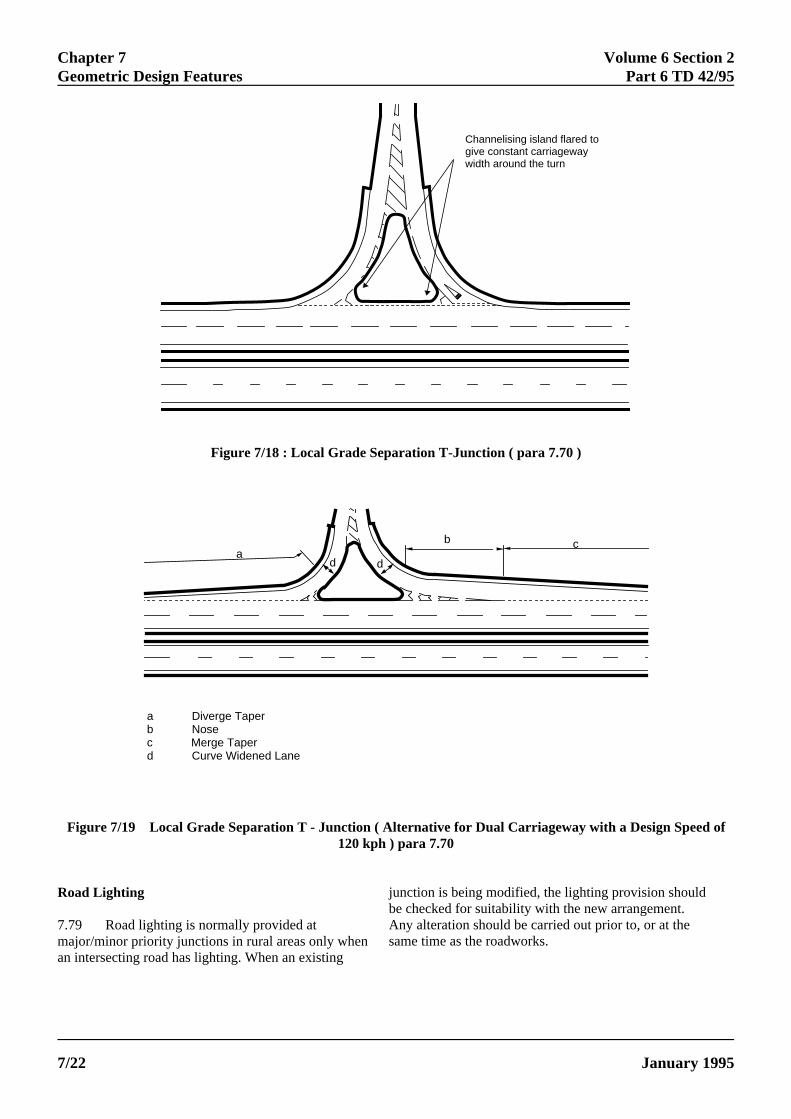
Chapter 7 Volume 6 Section 2Geometric Design Features Part 6 TD 42/95
f
Channelising island flared togive constant carriagewaywidth around the turn
ad d
b c
a Diverge Taperb Nosec Merge Taperd Curve Widened Lane
Figure 7/18 : Local Grade Separation T-Junction ( para 7.70 )
Figure 7/19 Local Grade Separation T - Junction ( Alternative for Dual Carriageway with a Design Speed o120 kph ) para 7.70
Road Lighting
7.79 Road lighting is normally provided atmajor/minor priority junctions in rural areas only whenan intersecting road has lighting. When an existing
junction is being modified, the lighting provision shouldbe checked for suitability with the new arrangement.Any alteration should be carried out prior to, or at thesame time as the roadworks.
ELECTRONIC COPY - NOT FOR USE OUTSIDE THE AGENCY
PAPER COPIES OF THIS ELECTRONIC DOCUMENT ARE UNCONTROLLED January 19957/22
Volume 6 Section 2 Chapter 8Part 6 TD 42/95 Assembly of Design Elements
8. ASSEMBLY OF DESIGN ELEMENTS
8.1 The overall aim in designing amajor/minor priority junction shall be to providedrivers with layouts that have consistent standardsand are not likely to confuse them. Whereverpracticable, the layout shall be designed so as tofollow the traffic pattern, with the principalmovements being given the easiest paths. Thisimproves the smoothness of operation and makes itmore readily understood by drivers. Unduly sharpradii or complex paths involving several changes indirection shall be avoided.
8.2 In Chapter 7, the components of designhave been considered separately, but the finallayout shall be looked at as a whole. It is importantthat, on entering a junction, drivers should be ableto see and understand, both from the layout andadvance traffic signs, the path they should follow,and the likely actions of crossing, merging anddiverging vehicles.
ELECTRONIC COPY - NOT
January 1995 PAPER COPIES OF THIS ELECTR
8.3 Figs 8/1 - 8/4 show how the componentparts can be assembled to produce the overalljunction design.
8.4 The designer shall aim to achieve the bestbalance between the design components in orderthat the overall junction works safely andefficiently, as described in para 8.1. The finalassessment of the design of a major/minor priorityjunction can only be carried out when looking atthe junction both as a whole, and in the context ofthose links and junctions adjacent to it on aparticular route. The designer shall consider thedesign from all the potential road users' point ofview and trace through the possible movements. Inparticular, the demands placed on the driver usingthe junction shall be considered bearing in mindwhat preceded arrival at the junction and what willfollow. It is important in particular to determinewhat will actually be visible to the driver as theyapproach the junction. This is what is termed the"driveability" objective in design.
FOR USE OUTSIDE THE AGENCY
ONIC DOCUMENT ARE UNCONTROLLED 8/1
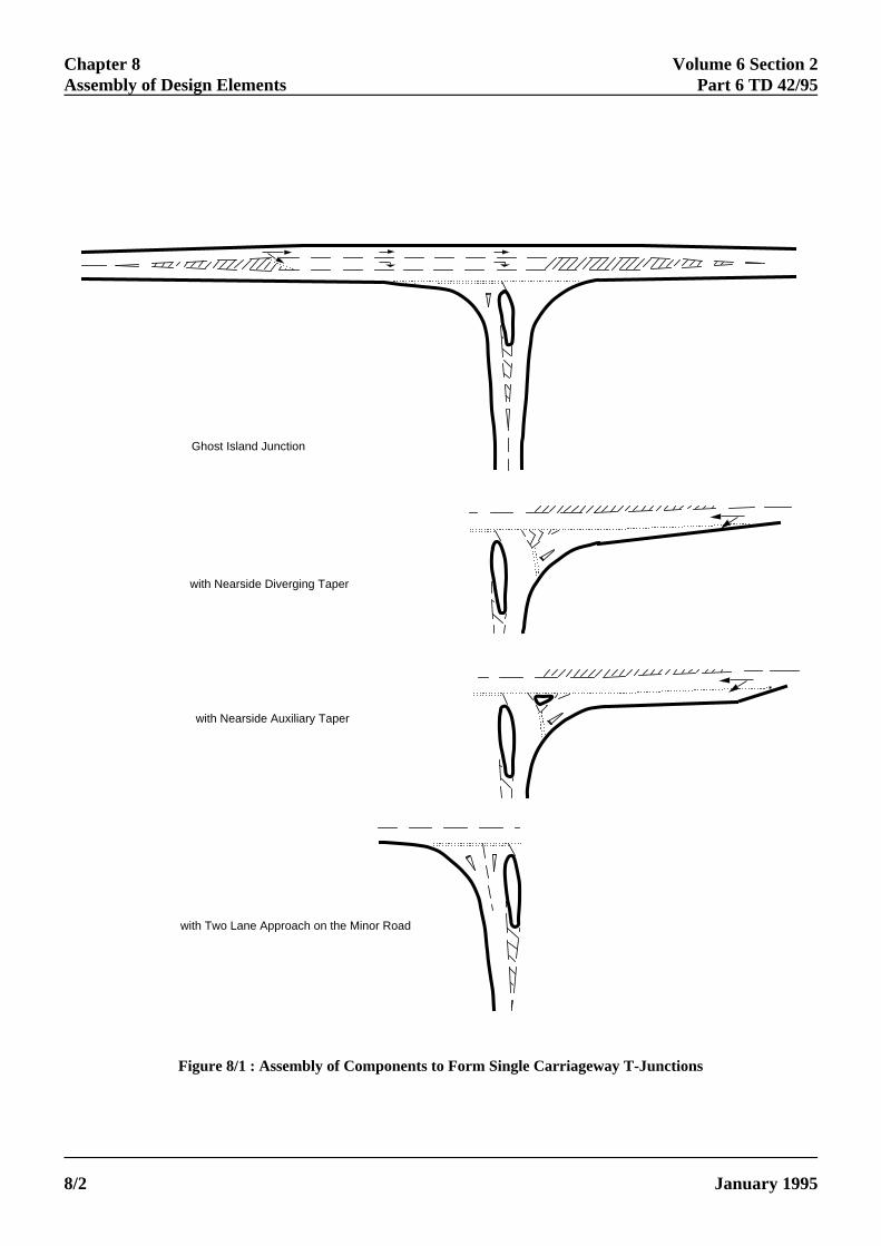
Chapter 8 Volume 6 Section 2Assembly of Design Elements Part 6 TD 42/95
Ghost Island Junction
with Nearside Diverging Taper
with Nearside Auxiliary Taper
with Two Lane Approach on the Minor Road
Figure 8/1 : Assembly of Components to Form Single Carriageway T-Junctions
ELECTRONIC COPY - NOT FOR USE OUTSIDE THE AGENCY
PAPER COPIES OF THIS ELECTRONIC DOCUMENT ARE UNCONTROLLED January 19958/2
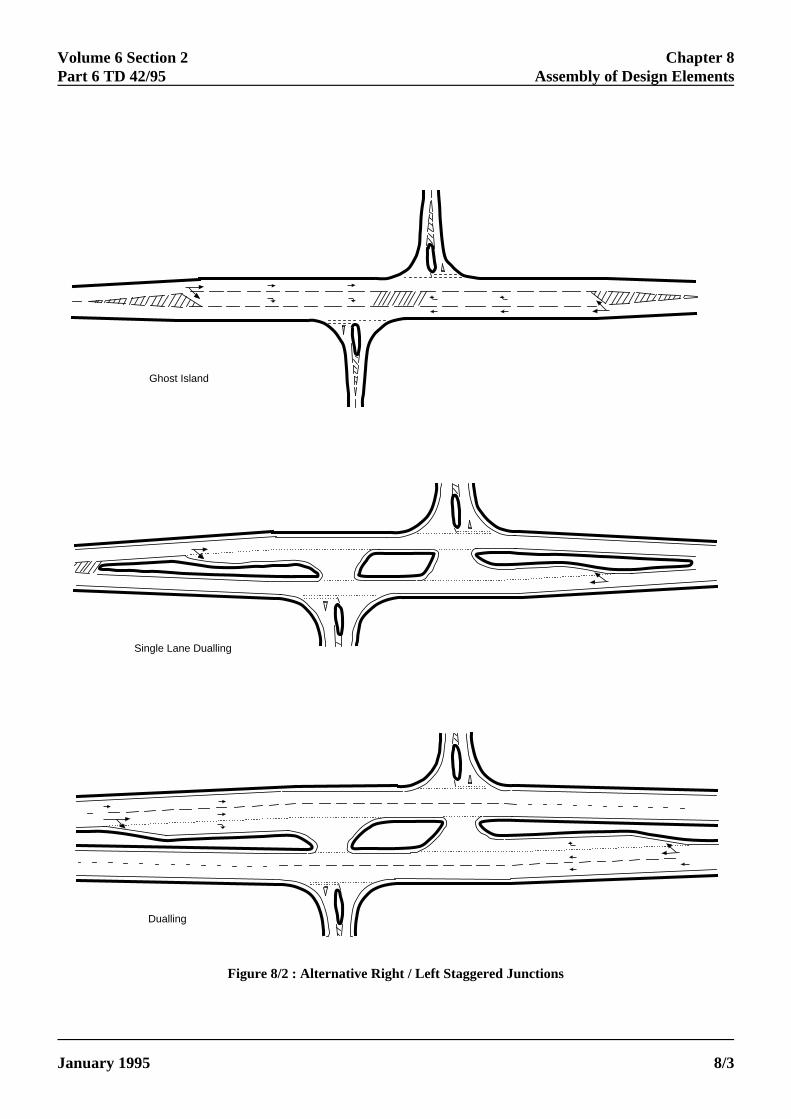
Volume 6 Section 2 Chapter 8Part 6 TD 42/95 Assembly of Design Elements
J
Ghost Island
Single Lane Dualling
Dualling
Figure 8/2 : Alternative Right / Left Staggered Junctions
ELECTRONIC COPY - NOT FOR USE OUTSIDE THE AGENCY
anuary 1995 PAPER COPIES OF THIS ELECTRONIC DOCUMENT ARE UNCONTROLLED 8/3
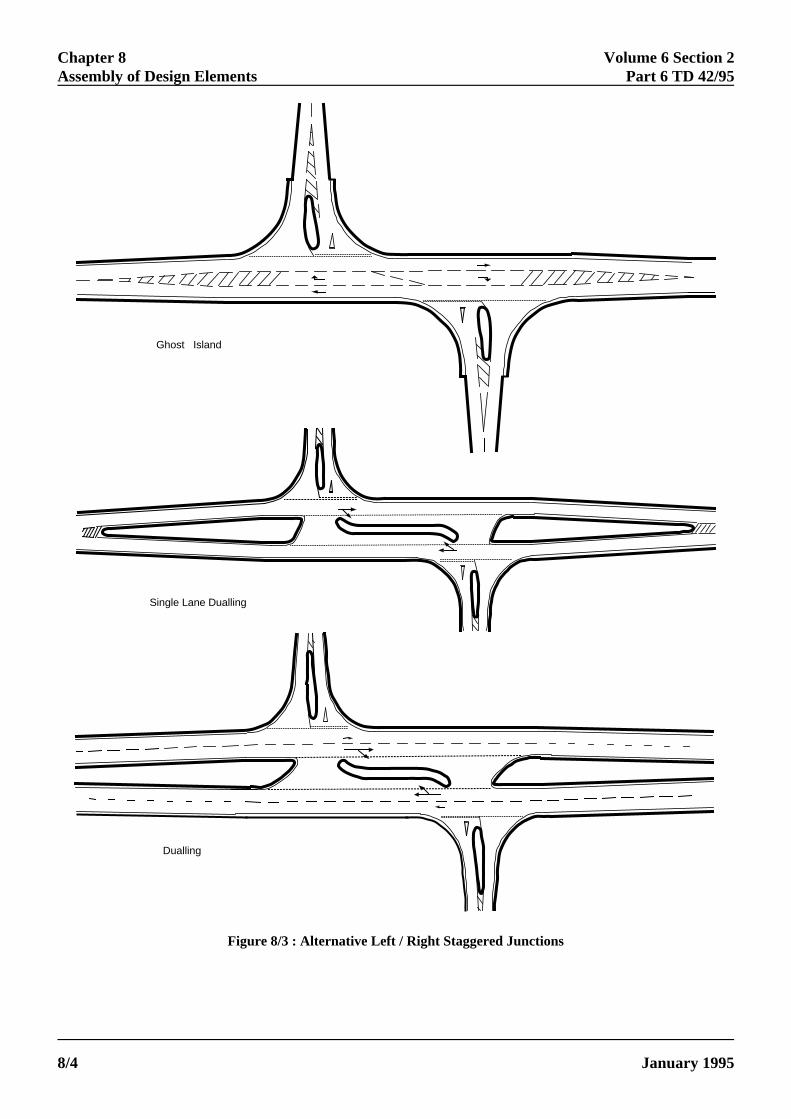
Chapter 8 Volume 6 Section 2Assembly of Design Elements Part 6 TD 42/95
8
Ghost Island
Single Lane Dualling
Dualling
Figure 8/3 : Alternative Left / Right Staggered Junctions
ELECTRONIC COPY - NOT FOR USE OUTSIDE THE AGENCY
PAPER COPIES OF THIS ELECTRONIC DOCUMENT ARE UNCONTROLLED January 1995/4
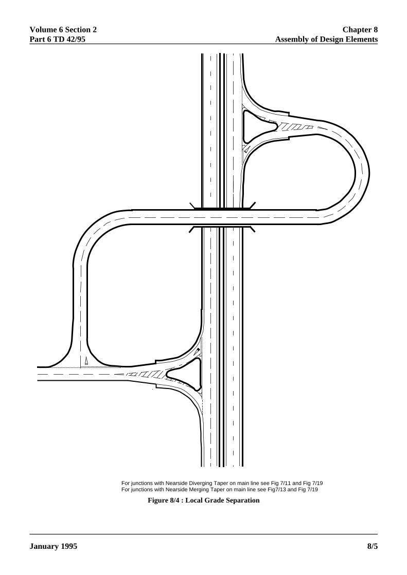
Volume 6 Section 2 Chapter 8Part 6 TD 42/95 Assembly of Design Elements
J
For junctions with Nearside Diverging Taper on main line see Fig 7/11 and Fig 7/19For junctions with Nearside Merging Taper on main line see Fig7/13 and Fig 7/19
Figure 8/4 : Local Grade Separation
ELECTRONIC COPY - NOT FOR USE OUTSIDE THE AGENCY
anuary 1995 PAPER COPIES OF THIS ELECTRONIC DOCUMENT ARE UNCONTROLLED 8/5
Volume 6 Section 2 Chapter 9Part 6 TD 42/95 References
9. REFERENCES
O.
al.
Design Manual for Roads and Bridges
a). Design Manual for Roads and Bridges, Volum2 Highway Structures: Design (Substructures andSpecial Structures), Materials, Section 2 SpecialStructures, BD 29 (DMRB 2.2) Design Criteria forFootbridges.
b). Design Manual for Roads and Bridges, Volume5 Assessment and Preparation of Road Schemes, Sec1 Assessment of Road Schemes, TA 30 (DMRB 5.1)Choice between Options for Trunk Road Schemes.
c). Design Manual for Roads and Bridges, Volum6 Road Geometry, Section 1 Links, Part 1, TD 9(DMRB 6.1.1) Highway Link Design.
d). Design Manual for Roads and Bridges, Volume6 Road Geometry, Section 2 Junctions, TA 23 (DMRB6.2) Determination of the Size of Roundabouts andMajor/Minor Junctions.
e). Design Manual for Roads and Bridges, Volum6 Road Geometry, Section 3 Highway Features, Part 1TD 36 (DMRB 6.3.1) Subways for Pedestrians andPedal Cyclists. Layout and Dimensions.
f). Design Manual for Roads and Bridges, Volume6 Road Geometry, Section 3 Highway Features, TA 57(DMRB 6.3) Roadside Features.
g). Design Manual for Roads and Bridges, Volume8 Traffic Signs and Lighting, Section 5 PedestrianCrossings, TD 28 (DMRB 8.5) Pedestrian Crossings:Pelican and Zebra Crossings.
h). Design Manual for Roads and Bridges, Volume8 Traffic Signs and Lighting, Section 5 PedestrianCrossings, TA 52 (DMRB 8.5) Design Considerationsfor Pelican and Zebra Crossings.
i). Design Manual for Roads and Bridges, Volume10 The Good Roads Guide.
L
aJ
bC
M
a
bJ
c
dR
ELECTRONIC COPY -
January 1995 PAPER COPIES OF THIS ELE
Traffic Signs Regulations
e a). SI 1994 No 1519 - The Traffic SignsRegulations and General Directions 1994: HMS
b) Traffic Signs Manual: HMSO
tion
e
e,
ocal Transport Notes
). Local Transport Note 1/86 Cyclists at Roadunctions and Crossings.
). Local Transport Note 2/86 Shared Use byyclists and Pedestrians.
iscellaneous
). Road Accidents in Great Britain 1991.
). TRL Report RR 65. Accidents at Rural T-unctions.
). Accident Investigation and Prevention Manu
) Road Vehicle (Construction and Use)egulations 1986.
NOT FOR USE OUTSIDE THE AGENCY
CTRONIC DOCUMENT ARE UNCONTROLLED 9/1
Volume 6 Section 2 Chapter 10Part 6 TD 42/95 Enquiries
ELECTRONIC COPY - NOT FOR USE OUTSIDE THE AGENCY
January 1995 PAPER COPIES OF THIS ELECTRONIC DOCUMENT ARE UNCONTROLLED 10/1
10. ENQUIRIES
All technical enquiries or comments on this document should be sent in writing as appropriate to:-
The Civil Engineering andEnvironmental Policy DirectorHighways AgencySt Christopher House T A ROCHESTERSouthwark Street Civil Engineering andLondon SE1 0TE Environmental Policy Director
The Deputy Chief EngineerThe Scottish Office Industry DepartmentRoads DirectorateNew St Andrew's House N B MacKENZIEEdinburgh EH1 3TG Deputy Chief Engineer
The Director of HighwaysWelsh OfficeY Swyddfa GymreigGovernment BuildingsTy Glas RoadLlanishen K J THOMASCardiff CF4 5PL Director of Highways
Chief Engineer - Roads ServiceDepartment of the Environment for Northern IrelandRoad Service HeadquartersClarence Court8 - 10 Adelaide Street W J McCOUBREYBelfast BT2 8GB Chief Engineer - Roads Service
Volume 6 Section 2Part 6 TD 42/95 Annex 1
CALCULATION OF CAPACITY
orofV) onrity
85% for next
, isparisonsign.
sed.
ered
givenulately
e
ies,
1. The formulae for capacity calculation formajor/minor priority junctions evaluate flows, allowingfor any conflict between the various traffic streams. Thecomputer program PICADY/3 has been developed tocarry out these calculations and evaluate queues, delaysand, in some cases, predict accident rates. Major/minorpriority junction flows, some of which are intermittentturning movements, are considered to be at "capacity"when there is continuous queuing feeding a particularturning movement. Not all movements need be at"capacity" for the junction to be considered at"capacity". 6.
2. The equations for the prediction of possibleminor road entry flows into a major/minor priorityjunction are a function of the through flow and entrygeometry at the junction. These equations are applicableto all types of major/minor priority T-junctions,including staggered junctions. Having developed arange of Design Reference Traffic Flows, a designershould use the equations to produce trial designs forassessment. Manual or computerised methods such asPICADY/3 may be used. However, it is not realistic tocalculate queue lengths and delays manually.
Ratio of Flow to Capacity
3. The ratio of flow to capacity (RFC) is anindicator of the likely performance of a junction underdesign year loading. It should be calculated or computedfor each trial design. Due to site to site variation, theremay be a standard error of prediction of the entrycapacity by the formulae of + or - 15% for any site.Thus, queuing should not occur in the various turningmovements in the chosen design year peak hour in 5 outof 6 peak hour periods or sites, if a maximum RFC ofabout 85% is used. Similarly, if a maximum RFC of75% is used, queuing will theoretically be avoided in 39out of 40 peak hour periods or sites.
4. The general use of designs with an RFC ofabout 85% is likely to result in a level of provisionwhich will be economically justified. However, at siteshaving no particular space restriction, and also wherethe Design Speed may be 100kph or more, usually insuburban and rural areas, the latter ratio, 75%, should beused as a design yardstick. This is because the formulaehave not been derived for roads of this type. In urbanareas, the former RFC, 85%, may be appropriate.
val
Var
7.quedisregnumave
ELECTRONIC COPY - NOT
January 1995 PAPER COPIES OF THIS ELECTR
5. Right turning queues and delays in the minroad should be virtually avoided in practice by use
the 75% RFC. The loss of Net Present Value (NPa typical road scheme containing major/minor prio
junctions by using the 75% factor instead of themay be relatively small in marginal cases where,
instance, the option between a ghost island and theupward step in the hierarchy, single lane duallingbeing investigated. Nevertheless, this sort of comshould be set down in the overall framework of de
Designers should not strive to obtain a unique
advantages and disadvantages of each one asses
Site to site variation has been estimated, and is covby the procedures. As far as day to day variation is
concerned, this will manifest itself in practice asvariations in the queue lengths and delays at anytime in the peak period. The formulae merely calcthe average over many days. PICADY/3 offers daivariability calculations as well as averages.
ue. A range of situations must be considered and th
iation
It must be stressed that the calculated capacitues and delays are average values of very broad
tributions. The formulae used are based on multipleression analyses from observations from a largeber of sites. Actual values can vary about the
rage due to:-
Site to site variation.Day to day variation.
FOR USE OUTSIDE THE AGENCY
ONIC DOCUMENT ARE UNCONTROLLED A1/1
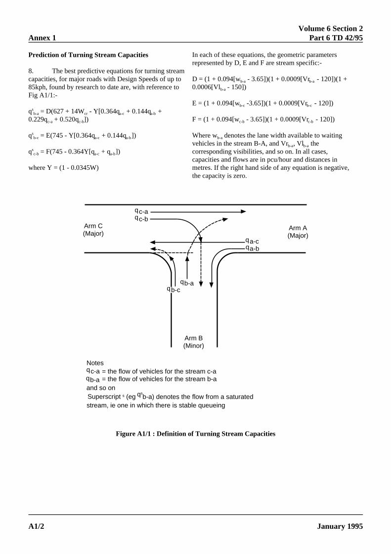
Volume 6 Section 2Annex 1 Part 6 TD 42/95
arametersific:-
- 120])(1 +
120])
- 120])
to waitingeases,
stances inn is negative,
Prediction of Turning Stream Capacities
8. The best predictive equations for turning streacapacities, for major roads with Design Speeds of up t85kph, found by research to date are, with reference tFig A1/1:-
q = D(627 + 14W - Y[0.364q + 0.144q +sb-a cr a-c a-b
0.229q + 0.520q ])c-a c-b
q = E(745 - Y[0.364q + 0.144q ])sb-c a-c a-b
q = F(745 - 0.364Y[q + q ])sc-b a-c a-b
where Y = (1 - 0.0345W)
ELECTRONIC COPY - NO
PAPER COPIES OF THIS ELECTA1/2
moo
In each of these equations, the geometric prepresented by D, E and F are stream spec
D = (1 + 0.094[w - 3.65])(1 + 0.0009[Vr b-a b-a
0.0006[Vl - 150])b-a
E = (1 + 0.094[w -3.65])(1 + 0.0009[Vr -b-c b-c
F = (1 + 0.094[w - 3.65])(1 + 0.0009[Vr c-b c-b
Where w denotes the lane width availableb-a
vehicles in the stream B-A, and Vr , Vl thb-a b-a
corresponding visibilities, and so on. In all ccapacities and flows are in pcu/hour and dimetres. If the right hand side of any equatiothe capacity is zero.
c-aqc-bq
b-aq
Arm C(Major)
a-cqa-bq
b-cq
Arm A(Major)
Arm B(Minor)
Notes= the flow of vehicles for the stream c-a= the flow of vehicles for the stream b-a
c-aq
b-aq
and so onSuperscript s (eg q
sb-a) denotes the flow from a saturated
stream, ie one in which there is stable queueing
Figure A1/1 : Definition of Turning Stream Capacities
T FOR USE OUTSIDE THE AGENCY
RONIC DOCUMENT ARE UNCONTROLLED January 1995
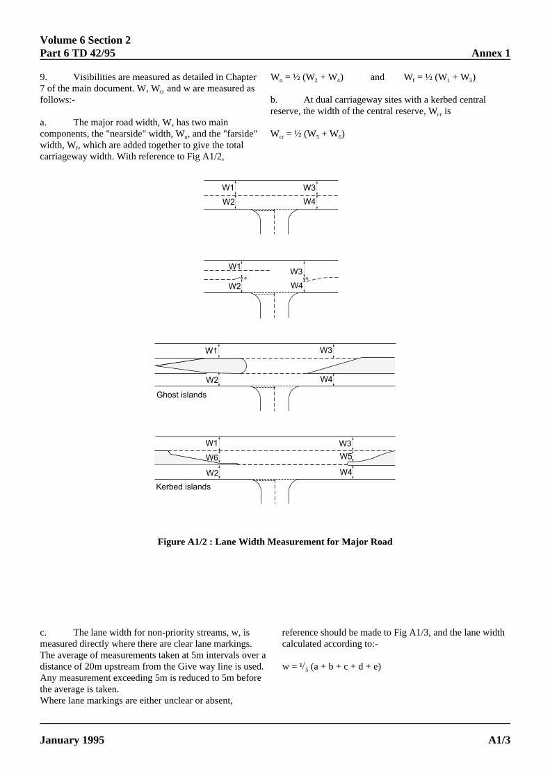
Volume 6 Section 2Part 6 TD 42/95 Annex 1
9. Visibilities are measured as detailed in Chapte7 of the main document. W, W and w are measured acr
follows:-
a. The major road width, W, has two maincomponents, the "nearside" width, W , and the "farsiden
width, W , which are added together to give the totalf
carriageway width. With reference to Fig A1/2,
January 1995 PAPER COPIES OF THIS ELECT
r W = ½ (W + W ) and W = ½ (W + W )s
b. At dual carriageway sites with a kerbed central
" W = ½ (W + W )
n 2 4 f 1 3
reserve, the width of the central reserve, W iscr
cr 5 6
W1
W2
W3
W4
W1
W2
W3
W4
W1
W2
W3
W4
W1
W2
W3
W4
W5W6
Ghost islands
Kerbed islands
°° °°
Figure A1/2 : Lane Width Measurement for Major Road
idth
ELECTRONIC COPY - NOT FOR USE OUT
c. The lane width for non-priority streams, w, is refemeasured directly where there are clear lane markings. cThe average of measurements taken at 5m intervals over adistance of 20m upstream from the Give way line is used. wª Any measurement exceeding 5m is reduced to 5m beforethe average is taken.Where lane markings are either unclear or absent,
5
RONIC
SIDE THE AGENCY
rence should be made to Fig A1/3, and the lane walculated according to:-
= ¹(a + b + c + d + e)
DOCUMENT ARE UNCONTROLLED A1/3
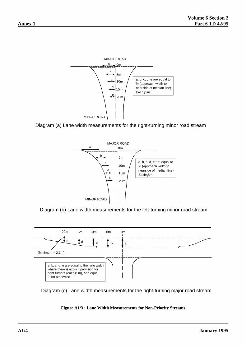
Volume 6 Section 2Annex 1 Part 6 TD 42/95
a
b
c
d
e
0m
5m
10m
15m
20m
MAJOR ROAD
a, b, c, d, e are equal to ½ (approach width tonearside of median line)Each<5m
MINOR ROAD
Diagram (a) Lane width measurements for the right-turning minor road stream
a
b
c
d
e
0m
5m
10m
15m
20m
MAJOR ROAD
a, b, c, d, e are equal to ½ (approach width tonearside of median line)Each<5m
MINOR ROAD
Diagram (b) Lane width measurements for the left-turning minor road stream
20m 15m 10m 5m 0m
e d c b a
(Minimum = 2.1m)
a, b, c, d, e are equal to the lane widthwhere there is explicit provision forright turners (each<5m), and equal2.1m otherwise
Diagram (c) Lane width measurements for the right-turning major road stream
Figure A1/3 : Lane Width Measurements for Non-Priority Streams
ELECTRONIC COPY - NOT FOR USE OUTSIDE THE AGENCY
PAPER COPIES OF THIS ELECTRONIC DOCUMENT ARE UNCONTROLLED January 1995A1/4
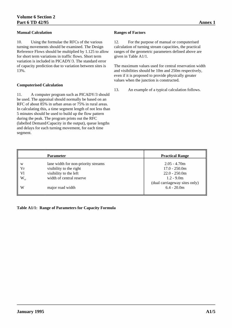
Volume 6 Section 2Part 6 TD 42/95 Annex 1
s.an
ths
Manual Calculation
10. Using the formulae the RFCs of the variousturning movements should be examined. The DesignReference Flows should be multiplied by 1.125 to allofor short term variations in traffic flows. Short termvariation is included in PICADY/3. The standard errorof capacity prediction due to variation between sites is13%.
Computerised Calculation
11. A computer program such as PICADY/3 shoube used. The appraisal should normally be based on RFC of about 85% in urban areas or 75% in rural areaIn calculating this, a time segment length of not less th5 minutes should be used to build up the flow patternduring the peak. The program prints out the RFC(labelled Demand/Capacity in the output), queue lengand delays for each turning movement, for each timesegment.
ELECTRONIC COPY -
January 1995 PAPER COPIES OF THIS ELE
Ranges of Factors
12. For the purpose of manual or computerisedcalculation of turning stream capacities, the practical
w ranges of the geometric parameters defined above aregiven in Table A1/1.
The maximum values used for central reservation widthand visibilities should be 10m and 250m respectively,
ldan
even if it is proposed to provide physically greatervalues when the junction is constructed.
13. An example of a typical calculation follows.
Parameter Practical Range
w lane width for non-priority streams 2.05 - 4.70mVr visibility to the right 17.0 - 250.0mVl visibility to the left 22.0 - 250.0mW width of central reserve 1.2 - 9.0mcr
W major road width 6.4 - 20.0m(dual carriageway sites only)
Table A1/1: Range of Parameters for Capacity Formula
NOT FOR USE OUTSIDE THE AGENCY
CTRONIC DOCUMENT ARE UNCONTROLLED A1/5
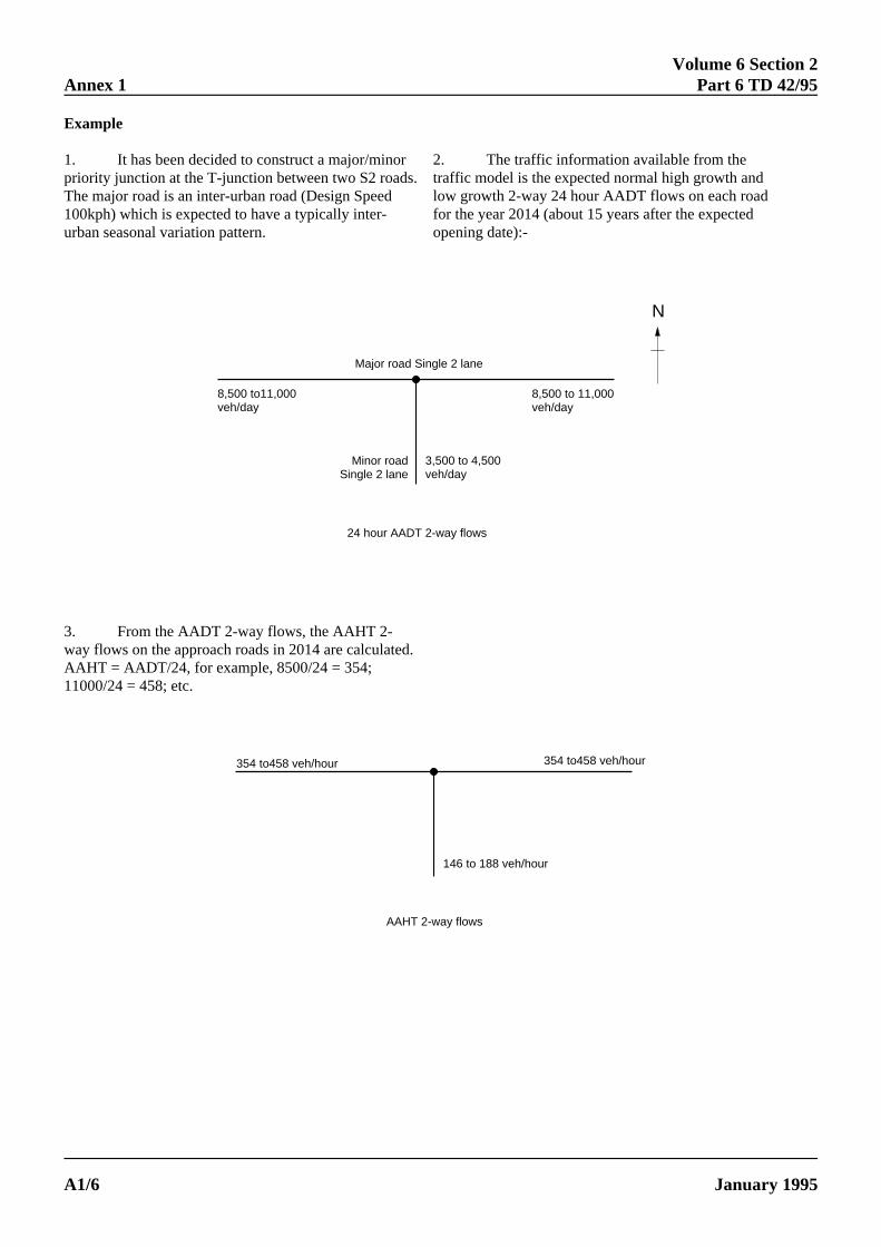
Volume 6 Section 2Annex 1 Part 6 TD 42/95
Example
1. It has been decided to construct a major/minpriority junction at the T-junction between two S2 roaThe major road is an inter-urban road (Design Speed100kph) which is expected to have a typically inter-urban seasonal variation pattern.
ELECTRONIC COPY - N
PAPER COPIES OF THIS ELECA1/6
ords.2. The traffic information available from thetraffic model is the expected normal high growth andlow growth 2-way 24 hour AADT flows on each roadfor the year 2014 (about 15 years after the expectedopening date):-
Major road Single 2 lane
8,500 to11,000veh/day
8,500 to 11,000veh/day
Minor roadSingle 2 lane
3,500 to 4,500veh/day
24 hour AADT 2-way flows
N
354 to458 veh/hour
146 to 188 veh/hour
AAHT 2-way flows
354 to458 veh/hour
3. From the AADT 2-way flows, the AAHT 2-way flows on the approach roads in 2014 are calculated.AAHT = AADT/24, for example, 8500/24 = 354;11000/24 = 458; etc.
OT FOR USE OUTSIDE THE AGENCY
TRONIC DOCUMENT ARE UNCONTROLLED January 1995
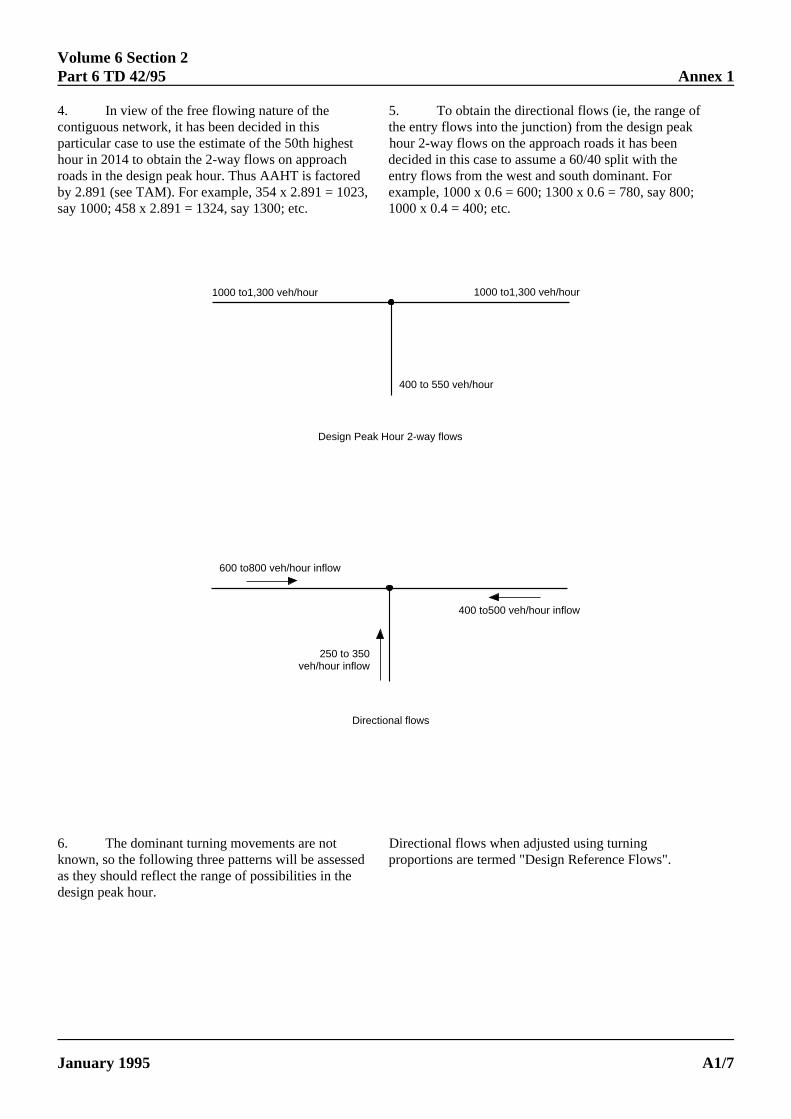
Volume 6 Section 2Part 6 TD 42/95 Annex 1
fkn
00;
4. In view of the free flowing nature of thecontiguous network, it has been decided in thisparticular case to use the estimate of the 50th highehour in 2014 to obtain the 2-way flows on approachroads in the design peak hour. Thus AAHT is factorby 2.891 (see TAM). For example, 354 x 2.891 = 10say 1000; 458 x 2.891 = 1324, say 1300; etc.
ELECTRONIC COPY - N
January 1995 PAPER COPIES OF THIS ELEC
5. To obtain the directional flows (ie, the range othe entry flows into the junction) from the design pea
st hour 2-way flows on the approach roads it has beedecided in this case to assume a 60/40 split with the
ed entry flows from the west and south dominant. For23, example, 1000 x 0.6 = 600; 1300 x 0.6 = 780, say 8
1000 x 0.4 = 400; etc.
1000 to1,300 veh/hour
400 to 550 veh/hour
Design Peak Hour 2-way flows
1000 to1,300 veh/hour
600 to800 veh/hour inflow
250 to 350 veh/hour inflow
Directional flows
400 to500 veh/hour inflow
".
6. The dominant turning movements are notknown, so the following three patterns will be assessas they should reflect the range of possibilities in thedesign peak hour.Directional flows when adjusted using turninged proportions are termed "Design Reference Flows
OT FOR USE OUTSIDE THE AGENCY
TRONIC DOCUMENT ARE UNCONTROLLED A1/7
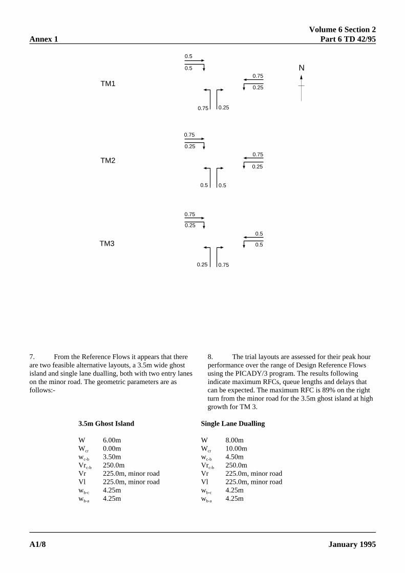
Volume 6 Section 2Annex 1 Part 6 TD 42/95
A1
0.5
0.5
0.25
0.250.75
0.75
0.75
0.25
0.75
0.25
0.5 0.5
0.75
0.25
0.5
0.5
0.25 0.75
TM1
TM2
TM3
N
e ak hourt Flowses g
ys thatht
igh
7. From the Reference Flows it appears that therare two feasible alternative layouts, a 3.5m wide ghosisland and single lane dualling, both with two entry lanon the minor road. The geometric parameters are asfollows:-
ELECTRONIC COPY - NOT FOR
PAPER COPIES OF THIS ELECTRONIC/8
8. The trial layouts are assessed for their peperformance over the range of Design Referenceusing the PICADY/3 program. The results followinindicate maximum RFCs, queue lengths and dela
can be expected. The maximum RFC is 89% on the rigturn from the minor road for the 3.5m ghost island at hgrowth for TM 3.
3.5m Ghost Island Single Lane Dualling
W 6.00m W 8.00mW 0.00m W 10.00mcr cr
w 3.50m w 4.50mc-b c-b
Vr 250.0m Vr 250.0mc-b c-b
Vr 225.0m, minor road Vr 225.0m, minor roadVl 225.0m, minor road Vl 225.0m, minor roadw 4.25m w 4.25mb-c b-c
w 4.25m w 4.25mb-a b-a
USE OUTSIDE THE AGENCY
DOCUMENT ARE UNCONTROLLED January 1995
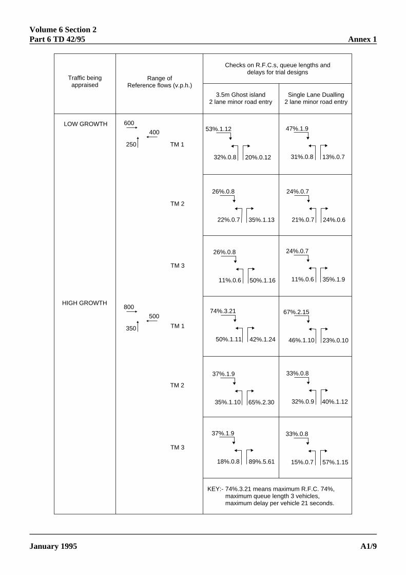
Volume 6 Section 2Part 6 TD 42/95 Annex 1
Traffic beingappraised
Range ofReference flows (v.p.h.)
Checks on R.F.C.s, queue lengths anddelays for trial designs
3.5m Ghost island2 lane minor road entry
Single Lane Dualling2 lane minor road entry
LOW GROWTH 600
250
400
TM 1
TM 2
TM 3
TM 1
HIGH GROWTH
TM 2
TM 3
74%.3.21 means maximum R.F.C. 74%, maximum queue length 3 vehicles,maximum delay per vehicle 21 seconds.
KEY:-
53%.1.12
32%.0.8 20%.0.12
47%.1.9
31%.0.8 13%.0.7
26%.0.8
22%.0.7 35%.1.13
24%.0.7
21%.0.7 24%.0.6
24%.0.7
11%.0.6 35%.1.9
26%.0.8
11%.0.6 50%.1.16
74%.3.21
50%.1.11 42%.1.24
67%.2.15
46%.1.10 23%.0.10
33%.0.8
32%.0.9 40%.1.12
37%.1.9
35%.1.10 65%.2.30
37%.1.9
18%.0.8 89%.5.61
33%.0.8
15%.0.7 57%.1.15
800
350
500
ELECTRONIC COPY - NOT FOR USE OUTSIDE THE AGENCY
January 1995 PAPER COPIES OF THIS ELECTRONIC DOCUMENT ARE UNCONTROLLED A1/9
Volume 6 Section 2Annex 1 Part 6 TD 42/95
9. The cost of traffic delays over the scheme life isevaluated for the two options at low and high growthusing COBA 9. The turning movements are modified toachieve balanced link flows on a daily basis, but thereare still three distinct cases of equal left and right turnsfrom the minor road, a predominant left turn from theminor road (75/25 split), and a predominant right turnfrom the minor road (25/75 split). The 3.5m ghost islandis estimated to cost £30,000 and single lane dualling£117,000, at 1993 prices. The COBA 9 results are asfollows (all discounted costs in thousands of pounds):-
First Scheme Year 1999
Traffic Figures 2014
Equal minor road turning movements
Construction Costs Delay CostsLow High
3.5m Ghost Island 18 270 408Single Lane Dualling - 72 - 258 - 384
- 54 + 12 + 24
Therefore Incremental NPV in going from a ghost island to single lane dualling is:-
Low Growth - 42High Growth - 30
Predominant left turn from minor road
Construction Costs Delay CostsLow High
3.5m Ghost Island 18 270 363Single Lane Dualling - 72 - 258 - 354
- 54 + 6 + 3
Therefore Incremental NPV in going from a ghost island to single lane dualling is:-
Low Growth - 48High Growth - 45
ELECTRONIC COPY - NOT FOR USE OUTSIDE THE AGENCY
PAPER COPIES OF THIS ELECTRONIC DOCUMENT ARE UNCONTROLLED January 1995A1/10
Volume 6 Section 2Part 6 TD 42/95 Annex 1
Predominant right turn from minor road
Construction Costs Delay CostsLow High
3.5m Ghost Island 18 306 489Single Lane Dualling - 72 - 285 - 432
- 54 + 21 + 57
Therefore Incremental NPV in going from a ghost island to single lane dualling is:-
Low Growth - 33High Growth + 3
dered ar roadction.ort the
10. Having examined the results it can be seen thathe only case of the suggested maximum RFC ratio of75% being exceeded is the right turn out of the majorroad for the ghost island at high growth when there is apredominant right turn from the minor road (89%, 5.61However, since the major road is 100kph design speedRFC values exceeding 75% should not be accepted (sparagraph 2.32). Additionally the differences in NPVbetween the ghost island option and the single lanedualling option are only small, therefore (other thingsbeing equal) the single lane dualling option should bechosen.
ELECTRONIC COPY - NO
January 1995 PAPER COPIES OF THIS ELECT
t In cases where single lane dualling is being consicheck must be made on the character of the majofor at least 3km on either side of the proposed junIf stretches of full dualling or local dualling occur (
). are likely to occur) then it would be prudent to adop, ghost island instead.ee
T FOR USE OUTSIDE THE AGENCY
RONIC DOCUMENT ARE UNCONTROLLED A1/11
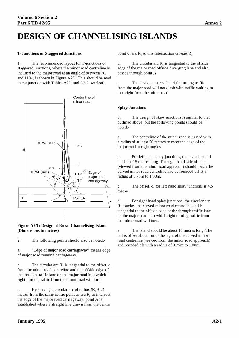
Volume 6 Section 2Part 6 TD 42/95 Annex 2
DESIGN OF CHANNELISING ISLANDS
d,f
2-4
Point A0
R1
R1+2
R2
0.3
0.30.75R(min)
d
Edge of major roadcarriageway
0.75-1.0 R2.5
Centre line of minor road
w40
T-Junctions or Staggered Junctions
1. The recommended layout for T-junctions orstaggered junctions, where the minor road centrelineinclined to the major road at an angle of between 70E
and 110E, is shown in Figure A2/1. This should be reain conjunction with Tables A2/1 and A2/2 overleaf.
Figure A2/1: Design of Rural Channelising Island(Dimensions in metres)
2. The following points should also be noted:-
a. "Edge of major road carriageway" means edof major road running carriageway.
b. The circular arc R is tangential to the offset, 1
from the minor road centreline and the offside edge othe through traffic lane on the major road into whichright turning traffic from the minor road will turn.
ELECTRONIC COPY - N
January 1995 PAPER COPIES OF THIS ELEC
c. By striking a circular arc of radius (R + 21
metres from the same centre point as arc R to in1
the edge of the major road carriageway, point A established where a straight line drawn from the
is
d
ge
point of arc R to this intersection crosses R .1 1
d. The circular arc R is tangential to the offside2
edge of the major road offside diverging lane and alsopasses through point A.
e. The design ensures that right turning trafficfrom the major road will not clash with traffic waiting toturn right from the minor road.
Splay Junctions
3. The design of skew junctions is similar to thatoutlined above, but the following points should benoted:-
a. The centreline of the minor road is turned witha radius of at least 50 metres to meet the edge of themajor road at right angles.
b. For left hand splay junctions, the island shouldbe about 15 metres long. The right hand side of its tail(viewed from the minor road approach) should touch thecurved minor road centreline and be rounded off at aradius of 0.75m to 1.00m.
c. The offset, d, for left hand splay junctions is 4.5metres.
d. For right hand splay junctions, the circular arcR touches the curved minor road centreline and is1
tangential to the offside edge of the through traffic laneon the major road into which right turning traffic fromthe minor road will turn.
e. The island should be about 15 metres long. Thetail is offset about 1m to the right of the curved minorroad centreline (viewed from the minor road approach)and rounded off with a radius of 0.75m to 1.00m.
OT FOR USE OUTSIDE THE AGENCY
TRONIC DOCUMENT ARE UNCONTROLLED A2/1
)tersect
iscentre
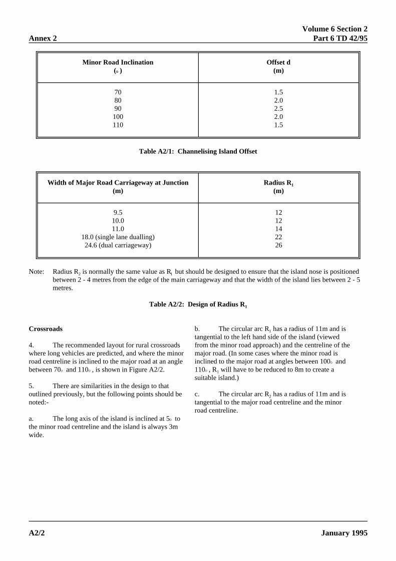
Volume 6 Section 2Annex 2 Part 6 TD 42/95
itioned 2 - 5
Minor Road Inclination Offset d(EE) (m)
70 1.580 2.090 2.5100 2.0110 1.5
Table A2/1: Channelising Island Offset
Width of Major Road Carriageway at Junction Radius R(m) (m)
1
9.5 1210.0 1211.0 14
18.0 (single lane dualling) 2224.6 (dual carriageway) 26
Note: Radius R is normally the same value as R but should be designed to ensure that the island nose is pos2 1
between 2 - 4 metres from the edge of the main carriageway and that the width of the island lies betweenmetres.
Table A2/2: Design of Radius R1
e
Crossroads
4. The recommended layout for rural crossroadswhere long vehicles are predicted, and where the minroad centreline is inclined to the major road at an anglbetween 70E and 110E, is shown in Figure A2/2.
5. There are similarities in the design to thatoutlined previously, but the following points should benoted:-
a. The long axis of the island is inclined at 5E tothe minor road centreline and the island is always 3mwide.
ELECTRONIC COPY - N
PAPER COPIES OF THIS ELECA2/2
ore
b. The circular arc R has a radius of 11m and is1
tangential to the left hand side of the island (viewedfrom the minor road approach) and the centreline of thmajor road. (In some cases where the minor road isinclined to the major road at angles between 100E and110E, R will have to be reduced to 8m to create a1
suitable island.)
c. The circular arc R has a radius of 11m and is2
tangential to the major road centreline and the minorroad centreline.
OT FOR USE OUTSIDE THE AGENCY
TRONIC DOCUMENT ARE UNCONTROLLED January 1995
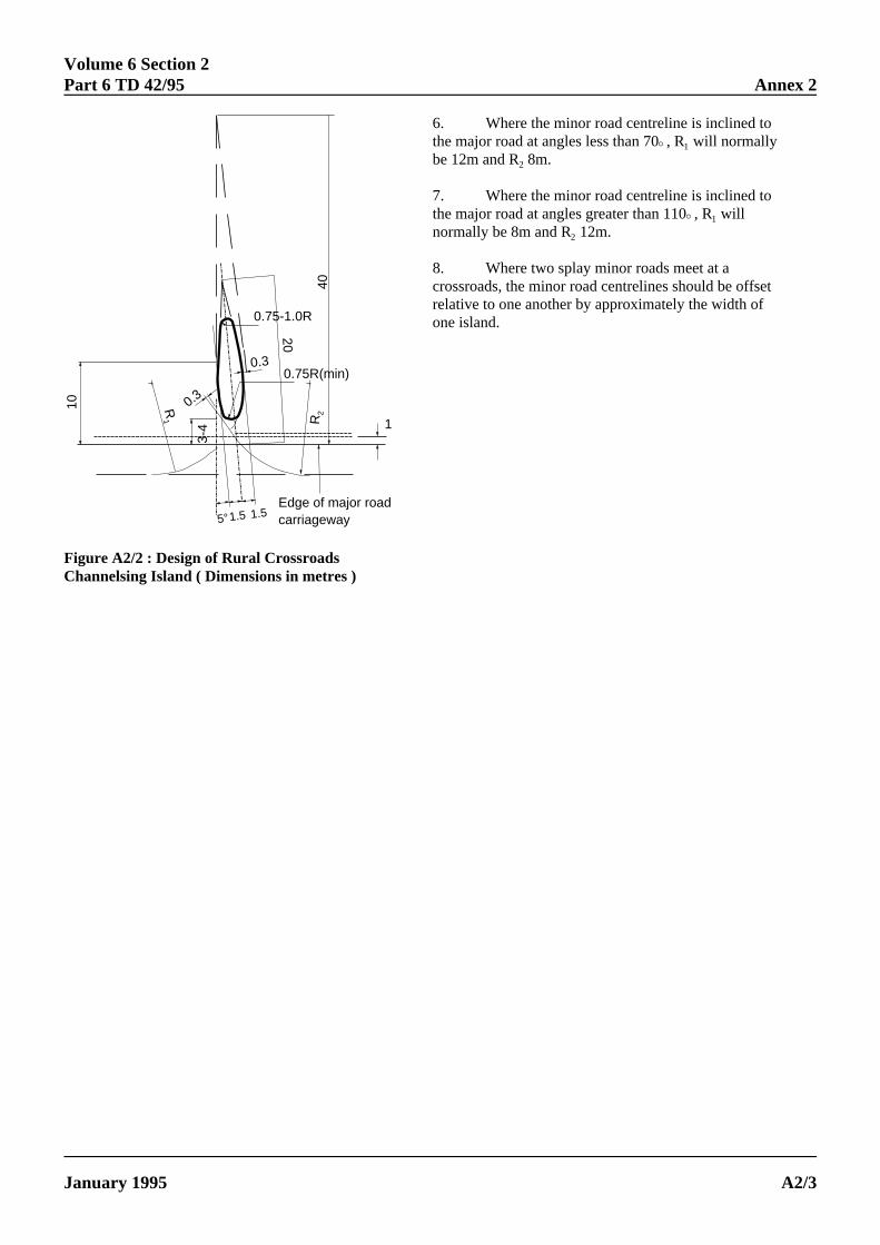
Volume 6 Section 2Part 6 TD 42/95
5°1.5 1.5Edge of major roadcarriageway
10 R1
0.3
3-4
0.30.75R(min)
R2
20
1
0.75-1.0R40
Figure A2/2 : Design of Rural CrossroadsChannelsing Island ( Dimensions in metres )
ELECTRONIC COPY - N
January 1995 PAPER COPIES OF THIS ELEC
Annex 2
6. Where the minor road centreline is inclined tothe major road at angles less than 70E, R will normally1
be 12m and R 8m.2
7. Where the minor road centreline is inclined tothe major road at angles greater than 110E, R will1
normally be 8m and R 12m.2
8. Where two splay minor roads meet at acrossroads, the minor road centrelines should be offsetrelative to one another by approximately the width ofone island.
OT FOR USE OUTSIDE THE AGENCY
TRONIC DOCUMENT ARE UNCONTROLLED A2/3