geometrical calibration of bi-planar radiography of the ... · geometrical calibration of bi-planar...
TRANSCRIPT

INE
B -
In
sti
tuto
de
En
ge
nh
ari
a
Bio
mé
dic
aGeometrical calibration of bi-planar
radiography of the spinefor common imaging systems
Daniel Moura, Jorge Barbosa, Joao Tavares, Ana Reis
INEB – Instituto de Engenharia Biomedica, Laboratorio de Sinal e ImagemFEUP – Faculdade de Engenharia da Universidade do PortoSMIC – Servico Medico de Imagem Computorizada, S. A
Introduction
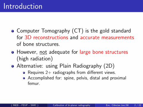
Computer Tomography (CT) is the gold standardfor 3D reconstructions and accurate measurementsof bone structures.
However, not adequate for large bone structures(high radiation)
Alternative: using Plain Radiography (2D)Requires 2+ radiographs from different views.Accomplished for: spine, pelvis, distal and proximalfemur.
( INEB – FEUP – SMIC ) Calibration of bi-planar radiography Enc. Ciencias Jun/08 2 / 22

Introduction: Geometrical calibration
For mapping 2D → 3D coordinates the imagingsystem must be calibrated on every examination.
Calibration of the spine is usually performed usinglarge calibration apparatus.Attempts have been made for using smallercalibration objects, but:
reconstruction errors are highercalibration objects overlap bone structures
( INEB – FEUP – SMIC ) Calibration of bi-planar radiography Enc. Ciencias Jun/08 3 / 22

Introduction: Goal
GoalAchieving accurate calibrations, while
making the method easy to implement in commonclinics
minimising the impact of calibration objects
( INEB – FEUP – SMIC ) Calibration of bi-planar radiography Enc. Ciencias Jun/08 4 / 22

Radiography calibration
Projection of a 3D point into a radiograph:w ·uw ·vw
= M ·
XYZ1
( INEB – FEUP – SMIC ) Calibration of bi-planar radiography Enc. Ciencias Jun/08 5 / 22

Radiography calibration
Projection of a 3D point: bi-planar radiographywi ·ui
wi ·vi
wi
= Mi ·
XYZ1
for i = 1, 2
( INEB – FEUP – SMIC ) Calibration of bi-planar radiography Enc. Ciencias Jun/08 6 / 22

Radiography calibration
Calibration Matrix (for flat detectors)
Mi =
fi/s 0 upi0
0 fi/s vpi0
0 0 1 0
· [Ri ti0T 1
]
f - focal length
(up, vp) - principal point
R, t - geometricaltransformation
( INEB – FEUP – SMIC ) Calibration of bi-planar radiography Enc. Ciencias Jun/08 7 / 22

Radiography calibration
Calibration Matrix (for flat detectors)
Mi =
fi/s 0 upi0
0 fi/s vpi0
0 0 1 0
· [Ri ti0T 1
]
f - focal length
(up, vp) - principal point
R, t - geometricaltransformation
f
X-ray device
X-ray source
Table
Detector( INEB – FEUP – SMIC ) Calibration of bi-planar radiography Enc. Ciencias Jun/08 7 / 22

Radiography calibration
Calibration Matrix (for flat detectors)
Mi =
fi/s 0 upi0
0 fi/s vpi0
0 0 1 0
· [Ri ti0T 1
]
f - focal length
(up, vp) - principal point
R, t - geometricaltransformation
f
X-ray device
X-ray source
Table
Detector
(up,vp)
( INEB – FEUP – SMIC ) Calibration of bi-planar radiography Enc. Ciencias Jun/08 7 / 22

Radiography calibration
Calibration Matrix (for flat detectors)
Mi =
fi/s 0 upi0
0 fi/s vpi0
0 0 1 0
· [Ri ti0T 1
]
f - focal length
(up, vp) - principal point
R, t - geometricaltransformation
t
X-ray device
X-ray source
Table
Detector
R
( INEB – FEUP – SMIC ) Calibration of bi-planar radiography Enc. Ciencias Jun/08 7 / 22

Radiography calibration
Calibration Matrix (for flat detectors)
Mi =
fi/s 0 upi0
0 fi/s vpi0
0 0 1 0
· [Ri ti0T 1
]
f - focal length
(up, vp) - principal point
R, t - geometricaltransformation
Calibration GoalFinding the values forthese parameters forboth views.
( INEB – FEUP – SMIC ) Calibration of bi-planar radiography Enc. Ciencias Jun/08 7 / 22

Determining the parameters values
1 Inputs:Initial solution for the parametersA set of point matches
2 Optimisation process (NLSQ):1 Triangulate point matches → 3D points2 Project 3D points → projected 2D points3 Minimise residuals between the original and the projected
points
( INEB – FEUP – SMIC ) Calibration of bi-planar radiography Enc. Ciencias Jun/08 8 / 22

Determining the parameters values
1 Inputs:Initial solution for the parametersA set of point matches
2 Optimisation process (NLSQ):1 Triangulate point matches → 3D points2 Project 3D points → projected 2D points3 Minimise residuals between the original and the projected
points
�(�TSMRX�SRMQEKI��
�(�TSMRX�SRMQEKI��
�(�TSMRX
4VSNIGXIH�(�TSMRX
4VSNIGXIH�(�TSMRX
QMRMQMWI�HMÙIVIRGI
QMRMQMWI�HMÙIVIRGI( INEB – FEUP – SMIC ) Calibration of bi-planar radiography Enc. Ciencias Jun/08 8 / 22

Determining the parameters values
1 Inputs:Initial solution for the parametersA set of point matches
2 Optimisation process (NLSQ):1 Triangulate point matches → 3D points2 Project 3D points → projected 2D points3 Minimise residuals between the original and the projected
points
ProblemOptimisation gets easily trapped in local minima.
( INEB – FEUP – SMIC ) Calibration of bi-planar radiography Enc. Ciencias Jun/08 8 / 22

Determining the parameters values
1 Inputs:Initial solution for the parametersA set of point matches
2 Optimisation process (NLSQ):1 Triangulate point matches → 3D points2 Project 3D points → projected 2D points3 Minimise residuals between the original and the projected
points
SolutionGood inputs :-)
( INEB – FEUP – SMIC ) Calibration of bi-planar radiography Enc. Ciencias Jun/08 8 / 22

Initial solution for spine radiographs
R1 =
[0◦ 0◦ 0◦
]t1 =
[0 0 ?
](up1 , vp1) = size(img1)/2f1 =?
R2 =[0◦ 90◦ 0◦
]t2 =
[0 0 ?
](up2 , vp2) = size(img2)/2f2 =?
( INEB – FEUP – SMIC ) Calibration of bi-planar radiography Enc. Ciencias Jun/08 9 / 22

Determining missing parameters
For narrowing the search space of solutions wepropose using a distance measuring device.
X-Ray imaging system
( INEB – FEUP – SMIC ) Calibration of bi-planar radiography Enc. Ciencias Jun/08 10 / 22

Determining missing parameters
For narrowing the search space of solutions wepropose using a distance measuring device.
X-ray device
X-ray source
Table
Detector
X-Ray imaging systemrepresentation
( INEB – FEUP – SMIC ) Calibration of bi-planar radiography Enc. Ciencias Jun/08 10 / 22

Determining missing parameters
For narrowing the search space of solutions wepropose using a distance measuring device.
f
X-ray device
X-ray source
Table
Detector
f – Focal distance
Distance between thex-ray source and thedetector
Can’t be measureddirectly
( INEB – FEUP – SMIC ) Calibration of bi-planar radiography Enc. Ciencias Jun/08 10 / 22

Determining missing parameters
For narrowing the search space of solutions wepropose using a distance measuring device.
t z
X-ray device
X-ray source
Table
Detector
tz – Z translation
Distance between thex-ray source and theobject
Can’t be measureddirectly
( INEB – FEUP – SMIC ) Calibration of bi-planar radiography Enc. Ciencias Jun/08 10 / 22

Determining missing parameters
For narrowing the search space of solutions wepropose using a distance measuring device.
fd m
X-ray device
X-ray source
Table
Detector
Distance measurer A distance measurer mayonly read dm
( INEB – FEUP – SMIC ) Calibration of bi-planar radiography Enc. Ciencias Jun/08 10 / 22

Determining missing parameters
For narrowing the search space of solutions wepropose using a distance measuring device.
f
d sd d
d m
X-ray device
X-ray source
Table
Detector
Distance measurer We implemented aprocedure for determining ds
and dd , which are constantfor a given system.
( INEB – FEUP – SMIC ) Calibration of bi-planar radiography Enc. Ciencias Jun/08 10 / 22

Determining missing parameters
For narrowing the search space of solutions wepropose using a distance measuring device.
f
d sd d
d m
X-ray device
X-ray source
Table
Detector
Distance measurer Knowing ds and dd enablesto determine f accuratelywith a distance measurer...
( INEB – FEUP – SMIC ) Calibration of bi-planar radiography Enc. Ciencias Jun/08 10 / 22

Determining missing parameters
For narrowing the search space of solutions wepropose using a distance measuring device.
t z
d sd m
X-ray device
X-ray source
Table
Detector
Distance measurer ... and to have an initialguess of tz .
( INEB – FEUP – SMIC ) Calibration of bi-planar radiography Enc. Ciencias Jun/08 10 / 22

Correcting scale
Even with this extension, this method is only able tocalculate up to scale solutions.
A reference distance (visible in both x-rays) isneeded to determine the scaling factor.
We propose using a simple calibration object (C.O.),which may be a bar of 8-12cm attached to patientsbacks.
scaling factor =known reference distance
reconstructed distance
( INEB – FEUP – SMIC ) Calibration of bi-planar radiography Enc. Ciencias Jun/08 11 / 22

Experiments
Currently, the main experiments are:Validation with a phantom object:
Validation in real environmentAccurate results in the presence of noiseTo appear in: CARS’08 (poster)
Simulation study with humanspines:
Validation in simulated environmentData extracted from CT scansUndergoing experiments show promisingresults
( INEB – FEUP – SMIC ) Calibration of bi-planar radiography Enc. Ciencias Jun/08 12 / 22

Experiments: Simulation using CT scan
Resolution:0.4× 0.4× 0.5mm3/voxel
Volume:205× 205× 517mm3
( INEB – FEUP – SMIC ) Calibration of bi-planar radiography Enc. Ciencias Jun/08 13 / 22

Experiments: Simulation using CT scan
DRR - AP projection DRR - Lateral projection
( INEB – FEUP – SMIC ) Calibration of bi-planar radiography Enc. Ciencias Jun/08 14 / 22

Experiments: Simulation using CT scan
3D landmarks: 6 per vertebra
DRR - AP projection DRR - Lateral projection
( INEB – FEUP – SMIC ) Calibration of bi-planar radiography Enc. Ciencias Jun/08 14 / 22

Simulation Process
( INEB – FEUP – SMIC ) Calibration of bi-planar radiography Enc. Ciencias Jun/08 15 / 22

Evaluation
3D reconstruction error (after aligning)
Spinal Length (SL)
Vertebral Body Height (VBH)
( INEB – FEUP – SMIC ) Calibration of bi-planar radiography Enc. Ciencias Jun/08 16 / 22

Evaluation
3D reconstruction error (after aligning)
Spinal Length (SL)
Vertebral Body Height (VBH)
( INEB – FEUP – SMIC ) Calibration of bi-planar radiography Enc. Ciencias Jun/08 16 / 22

Evaluation
3D reconstruction error (after aligning)
Spinal Length (SL)
Vertebral Body Height (VBH)
( INEB – FEUP – SMIC ) Calibration of bi-planar radiography Enc. Ciencias Jun/08 16 / 22

First Experiment
Does the position of the C.O. affects results?If so, can we tell where to place the C.O. for bestresults?
( INEB – FEUP – SMIC ) Calibration of bi-planar radiography Enc. Ciencias Jun/08 17 / 22

First Experiment: Conclusions
Effects of the C.O. positionMean 3D errors: negligibleMean VBH: negligibleSL: highly dependable
Experimentally, we determined that the best C.O.position (left vs. right) depends of two factors:
1 Patient rotation2 C.O. position: anterior vs. posterior
( INEB – FEUP – SMIC ) Calibration of bi-planar radiography Enc. Ciencias Jun/08 18 / 22

Second Experiment
Experiment goal: simulating a real scenarioConditions:
Noise: Gaussian, typical range of values1
C.O.: placed only in good positions
Results (mm):
VBH SL
In Vivo1
3D
In Vitro2
RMS 0.9 1.4 1.8Mean 0.9 0.9
2.1
1.8
2.1
StD 0.2 1.2
1.0
0.4
1.5
1Kadoury et al. (2007). Med. Bio. Eng. Comp., 45(6):591–602.2Aubin et al. (1997). Med. Bio. Eng. Comp., 35(6):611–618.
( INEB – FEUP – SMIC ) Calibration of bi-planar radiography Enc. Ciencias Jun/08 19 / 22

Second Experiment
Experiment goal: simulating a real scenarioConditions:
Noise: Gaussian, typical range of values1
C.O.: placed only in good positions
Results (mm):
VBH SL In Vivo1 3D
In Vitro2
RMS 0.9 1.4 1.8Mean 0.9 0.9 2.1 1.8
2.1
StD 0.2 1.2 1.0 0.4
1.5
1Kadoury et al. (2007). Med. Bio. Eng. Comp., 45(6):591–602.
2Aubin et al. (1997). Med. Bio. Eng. Comp., 35(6):611–618.
( INEB – FEUP – SMIC ) Calibration of bi-planar radiography Enc. Ciencias Jun/08 19 / 22

Second Experiment
Experiment goal: simulating a real scenarioConditions:
Noise: Gaussian, typical range of values1
C.O.: placed only in good positions
Results (mm):
VBH SL In Vivo1 3D In Vitro2
RMS 0.9 1.4 1.8Mean 0.9 0.9 2.1 1.8 2.1StD 0.2 1.2 1.0 0.4 1.5
1Kadoury et al. (2007). Med. Bio. Eng. Comp., 45(6):591–602.2Aubin et al. (1997). Med. Bio. Eng. Comp., 35(6):611–618.( INEB – FEUP – SMIC ) Calibration of bi-planar radiography Enc. Ciencias Jun/08 19 / 22

Conclusions
Simulations show that the method has comparableaccuracy with other methods
... still, in vivo or in vitro validation should be performed.
Advantageous:C.O. does not need to overlap the spineC.O. is easy to buildCompensates patient movement between acquisitionsLow budget
Main Disadvantageous:Requires several points to be handmarkedNeeds an initial calibration procedureInstallation of a measuring device
( INEB – FEUP – SMIC ) Calibration of bi-planar radiography Enc. Ciencias Jun/08 20 / 22

Future work
1 Simulations with more CT scans (VHP)2 Designing and prototyping the Calibration Object3 In vitro experiment with a dried human spine4 Experiments using 2 calibration objects
5 Semi-automatic detection of landmarks
( INEB – FEUP – SMIC ) Calibration of bi-planar radiography Enc. Ciencias Jun/08 21 / 22

INE
B -
In
sti
tuto
de
En
ge
nh
ari
a
Bio
mé
dic
a
Thank You!
Daniel Moura, Jorge Barbosa, Joao Tavares, Ana Reis
INEB – Instituto de Engenharia Biomedica, Laboratorio de Sinal e ImagemFEUP – Faculdade de Engenharia da Universidade do PortoSMIC – Servico Medico de Imagem Computorizada, S. A