geometrical considerations and nomenclature for … considerations and nomenclature for ... details...
TRANSCRIPT
Geometrical Considerations and Nomenclature for Reflectance
F.E. Nicodemus, J.C. Richmond, and J.J. Hsia
Institute for Basic Standards National Bureau of Standards Washington, D.C. 20234
and
I.W. Ginsberg
EG&G, Inc. Las Vegas, Nevada 89101
and
T. Limperis
A g o Sciences, Inc. Ann Arbor, Michigan 48103
U.S. DEPARTMENT OF COMMERCE, Juanita M. Kreps, Secretary
Dr. Sidney Harman, Under Secretary Jordan J. Baruch, Assistant Secretary for Science and Technology
NATIONAL BUREAU OF STANDARDS, Ernest Ambler, Acting Director
Issued October 1977

For sale by the Superintendent of Documents, U.8. Government Printing 05ce Washington, D.C. 20402 - Price $2.10
Stock No. OoaM)3-01793

Contents
I. 11.
111.
IV.
V.
Introduction _ - _ _ _ _ _ _ _ _ _ _ _ _ _ _ _ _ _ _ - _ _ _ _ _ _ _ _ _ _ _ _ _ _ - _ _ _ - _ - _ _ _ _ _ _ _ _ _ _ _ _ _ _ _ _ _ _ _ _ Reflectance Concepts and Nomenclature _ _ _ _ _ _ _ _ _ _ _ _ _ _ _ _ _ _ _ _ _ _ _ _ _ _ _ _ _ _ _ _ _ _
A. Bidirectional Reflectance-Distribution Function (BRDF) _ _ _ _ _ _ _ _ _ _ _ _ _ _ B. Definitions of Reflectance and Reflectance Factor _ _ _ _ _ _ _ _ _ _ _ _ _ _ _ _ _ _ _ _ C. Reflectances and Reflectance Factors for Nine Geometries _ - _ _ _ _ _ _ _ _ - -
Some Additional Reflectance-Nomenclature Possibilities _ _ _ _ _ _ _ _ _ _ _ _ _ _ _ _ _ _ _ _ A. McCamy's Notation for Right Circular Cones _ _ _ _ _ _ _ _ _ _ _ _ _ _ _ _ _ _ _ _ _ _ _ _ _ _ B. Multivariate Reflectance-Distribution Functions (MRDF's) _ _ _ _ _ _ _ _ _ _ _ _ C. Other Special Types (BRIDF and BRRDF) _ _ _ _ _ _ _ _ _ _ _ _ _ _ _ _ _ _ _ _ _ _ _ _ _ _ _ _
Practical Considerations for Measurement of Reflectance _ _ _ - _ _ _ _ _ _ _ _ _ _ - - _ _ A. Effects of Fmite Intervals _ _ _ _ _ _ _ _ _ _ _ _ _ _ _ _ _ _ _ _ _ _ _ _ _ _ _ _ _ _ _ _ _ _ _ _ _ _ _ _ _ _ _ _ B. Definition of Reflecting-Surface Area - _ _ _ _ _ _ _ _ _ _ _ _ _ _ _ _ _ _ _ _ _ _ _ _ _ _ _ _ _ _ - C. Sub-Surface Scattering (Edge Effects) . . . . . . . . . . . . . . . . . . . . . . . . . . . . . . . . D. Extrapolation to Different Geometries _ _ _ _ _ _ _ _ _ _ _ _ _ _ _ _ _ _ _ _ _ _ _ _ _ _ _ _ _ _ _ _ E. Other Radiation Parameters and Fluorescence (or Phosphorescence) _ _ F. Use of Reference Standards . . . . . . . . . . . . . . . . . . . . . . . . . . . . . . . . . . . . . . . . . .
Summary, Conclusions, and Recommendations _ _ _ _ _ _ _ _ _ _ _ _ _ _ _ _ _ _ _ _ _ _ _ _ _ _ _ _
. . . .
Page
1 3 3 7 9
12 12 14 19 20 21 24 28 30 30 32 33
Appendices VI. 34 VII. B. Details of Reflectance Derivations (A Thought Experiment)________--__ 37 VIII. 43 IX. D. Details for Derivations of McCamy's Notation . . . . . . . . . . . . . . . . . . . . . . . . 46 X. Acknowledgments _ _ _ _ _ _ _ _ _ _ _ _ . . . . . . . . . . . . . . . . . . . . _ _ _ _ _ _ _ _ _ _ _ _ _ _ _ _ _ _ _ _ _ - _ _ 50 XII. References _ _ _ _ _ _ _ _ _ _ _ _ _ _ _ _ _ _ _ _ - - _ _ - _ _ _ _ _ _ - - - _ _ - - _ - - _ _ _ _ _ _ - _ _ _ _ _ _ _ _ _ _ - - - - 51
A. Background and Basis for Recommendations - _ _ _ _ _ _ _ _ _ _ _ _ _ _ _ _ _ _ _ _ _ _ _
C. Perfectly Diffuse and Perfectly Specular Reflectances _ _ _ _ _ _ _ _ _ _ - _ _ _ _ _
Illustrations
Figure 1.
2.
3.
4.
5.
6.
Geometry of incident and reflected beams (for general cases where sub- surface scattenng is involved) _ _ _ _ _ _ _ _ _ _ _ _ _ _ _ _ _ _ _ _ _ _ _ _ _ _ _ _ _ _ _ _ _ _ _ _ _ _ _ _ - _ _ _ 4 . . .
Geometry of incident and reflected elementary beams (2 axis is chosen along the normal to the surface element dA at 0.) (Adapted from [lo]) 6
Designations for denoting incident- and reflected- (collected-) beam geometry- _ 10
McCamy's notation for right circular cones _ _ _ _ _ _ _ _ _ _ _ _ _ _ _ _ _ _ _ _ _ _ _ _ _ _ _ _ _ _ _ _ 13
Three-dimensional graph of bidirectional rejkctance-distribution function (BRDF)f,(33.2", 0"; 0'4) (from [lo]) _ _ _ _ _ _ _ _ _ _ _ _ _ _ _ _ _ _ _ _ _ _ _ _ _ _ _ _ _ _ _ _ _ _ _ _ _ _ _ _ 22
Three configurations I for physically defining the reflecting area. (See sec. 1V.C concerning important limitations arising from subsurface scattering or edge effects".) _ _ _ _ _ _ _ _ _ _ _ _ _ _ _ _ _ _ _ _ _ _ _ _ _ _ _ _ _ _ _ _ _ _ _ _ _ _ _ _ _ _ - _ _ _ _ - _ _ _ _ _ _ _ _ - _ _ _ 25 66
... 111
Page
26 Simplified configuration when source (or receiver) is located in focal plane (or just behind field stop in focal plane) of primary optics . . . . . . . . . . . . . . . . . . . . . .
7.
8.
9.
10.
11.
12.
13.
Table 1.
2.
3.
4.
Simplified configuration with source (or receiver) and sample (reflecting surface) in conjugate image planes of primary optics _ _ _ _ _ _ _ _ _ _ _ _ _ _ _ _ _ _ _ _ _ _ _ _ 27
“Thought-experiment” configuration for bidirectional reflectance _ _ _ _ _ - _ - - - - - 38
“Thoughfrexperiment” configuration for directional-conical reflectance _ _ _ _ _ _ 40
“Thought-experiment” configuration for conical-directional reflectance _ _ _ _ _ _ 41
Construction for deriving relationships between spherical coordinates and McCamy’s notation for right-circular cones - - _ _ _ - - - - - - - _ _ _ _ _ _ _ _ _ _ _ - - - _ _ _ _ _ _ 47
Details of the construction of figure 12 _________- - - -__ -____________________ 48
Tables
Proposed nomenclature for nine kinds of reflectance - - - - - -- -- - - - _ - - _ - - - -- -- -
Proposed nomenclature for nine reflectance factors - - - - - - - - - - - - - - - - - - - - - - - -
The multivariate reflectance-distribution functions - ~ ~ _ - _ - - - - - - - -_ - -_ - -- -- -
Comparison between recommended reflectance nomenclature and that of [lo]
11
12
15
35
iv

List of Abbreviations
Abbreviation Term
BRDF bidirectional reflectance-distribution function BRIDF bidirectional reflected-intensity-distribution function QRRDF bidirectional reflected-radiance-distribution function BSSRDF bidirectional scattering-surface reflectance-distribution
MRDF multivariate reflectance-distribution function RDF reflectance-distribution function SI
ORDF avariate reflectance-distribution function lRDF univariate reflectance-distribution function 2RDF bivariate reflectance-distribution function 3RDF trivariate reflectance-distribution function 4RDF quadrivariate reflectance-distribution function
function
Systkme International d'Unites (the International System of Units)
Symbol
A a
C C
Term __
area area
constant speed o f light
irradiance
frequency
function
BRDF
spectral BRDF
relative spectral BRDF
List o f Symbols
Explanation Unit-Dimension
of a surface: = ssdx .dy of a band of diminishing
with respect to wavelength [XI electromagnetic radiation- [m .s-']
[m'] [m']
reflected radiance; a(r,)
in empty space; = (2.997
0 1 2 ) ~ 10" [m.s-'] incident flux (surface) den-
sity; d @ / d A of modulation or fluctua- [Hz]
tion; f<<v of the quantities or param-
eters in the parentheses bidirectional reflectance- [sr-l J
distribution function spectral bidirectional re- [sr-']
flectance-distribution function
reflectance-distri bution function
924 58 2 0.000 000
[W . m-'1
. . .
separable relative spectral [.dimensionless]
Defined or used in sec., eq, table, etc.
I1.A [eq (71. 1II.C [eq (26)]. 1II.C [eq (25)l. 1I.A [eqs (1) & (2)l.
1II.B [table 31. 1II.C. List of Unit-
Dimensions. 1II.B [table 31. 1II.B [table 31. 1II.B [table 31. 1II.B [table 31. 1II.B [table 31.
Defined or usec in sec., eq, table, fig., etc.
I1.A [eq (91 . 1V.C [eq (34)].
1V.E. I (footnote).
1I.A [eq (4)].
I (footnote).
1I.A [eq (9)].
1I.A [eq (611.
1V.E [eq (38)].
1V.E [eq (a)].
V

List of Svmbols (continued)
Symbol
* ) f r ( . . . ; .. -
LI (t'i 94i ; Or,&)
LL (4 ,4i; e r , 4 r )
H (obs.)
I
J (obs.) L 1
M
m
N (obs.) n
P (obs.)
R
R
Term - Explanation Unit-Dimension
average RDF for [see note at end of table 3, indicated and accompanying text, beam geome- concerning special rules try for designating parame-
ter intervals for such av- eraging in the MRDF scheme]
tensity-distribution func- tion
ance-distribution func- tion
(now used for exposure- in [J-m-2])
[sr-'1
BRIDF bidirectional reflected-in- [sr-']
BRRDF bidirectional reflected-radi- [sr-'1
irradiance [obsolete-replaced by E 3 [W . m-2 I
radiant intensity exitent flux per unit solid [Wesr-'1
radiant intensity [obsolete-replaced by I] [W . sr-'] radiance d2@/(dA.cost'*dw) [W.m-2 asr-'] direction cosine
(of a source) angle; d@/dw
of cone axis with respect to [dimensionless] X-axis; = xdp0; used in App. D only.
radiant exitance exitent flux (surface) den- [W .m-21 sity; = d@/dA
direction cosine Y-axis; = yo/po; used in App. D only
of cone axis with respect to [dimensionless]
radiance [obsoletereplaced by L ] [W .m-2 -sr- 'l direction cosine of cone axis with respect to [dimensionless]
Z-axis; = zo/po; used in App. D only
radiant flux [obsolete-replaced by @] [W]
reflectance fac- = d@A&rid [dimensionless]
receiver [designation used in figs. 9, *
(power)
tor
10, and 11, and accom- panying text only]
Defined or used in sec., eq, table, fig., etc.
1II.B [table 31.
1II.C [eq (26)].
1II.C [eq (25)l.
App. A [table 41.
1II.C [eq (26)].
App. A [table 43; 1I.A [eq (l)]. APP. D [eq (D3)I.
App. A [table 41. APP. D [eq (W1.
App. A [table 41.
II.B.2 [eq (18)l.
App. B [figs. 9, 10, and 111.
vi
List of Symbols (continued)
Symbol - Term Explanation Unit-Dimension
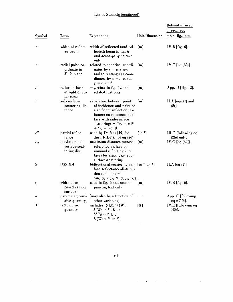
r
1
S
S
U
X
width of reflect- ed beam
radial polar co- ordinate in X-Y plane
radius of base of right circu- lar cone
sub-surface- scattering dis- tance
partial reflec- tance
maximum sub- surface-scat- tering dist.
BSSRDF
width of ex- posed sample surface
parameter; vari- able quantity
radiometric quantity
width of reflected (and col- [m] lected) beam in fig. 6 and accompanying text only
nates by r = p.sin8; and to rectangular coor- dinates by x = r .cos+, y = r.sin+
related text only
related to spherical coordi- [m]
= p*sinK in fig:l2 and [m]
separation between point [m] of incidence and point of significant reflection (ex- itance) on reference sur- face with sub-surface scattering; = [(x, - xi)' + fyr - ~ i ) ' l * .
used by De Vos [19] for
maximum distance (across [m]
[sr-l] the BRIDFf,, of eq (26)
reference surface or nominal reflecting sur- face) for significant sub- surface-scattering
face reflectance-distribu- tion function; =
bidirectional scattering-sur- [m-' . sr-l]
S(8i ,+i ,xi ,yi; Hr,+rrxrr yr) used in fig. 6 and accom- [m]
panying text only
[may also be a function of . . . other variables]
I [W .sr-I], E or M [W .m-2], or L[W.m-2*sr-1]
includes: Q [J], [W], [XI
Defined or used in sec., eq, table, fig., etc.
1V.B [fig. 61.
1V.C [eq (32)].
App. D [fig. 121.
1I.A [eqs (7) and (811.
1II.C [following eq (26)] only.
1V.C [eq (32)].
1I.A [eq (2)].
1V.B [fig. 61.
App. C [following
1V.E [following eq eq (CWI.
(4Q)I.
vii
List of Symbols (continued)
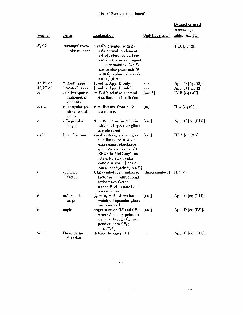
P
P
P
Defined or used in sec., eq,
Term Explanation Unit-Dimension table, fig., etc.
rectangular-co- usually oriented with Z - . . . 1I.A [fig. 21. ordinate axes axis normal to element
dA of reference surface and X-Y axes in tangent plane containing d A ; Z- axis is also polar axis (0 = 0) for spherical coordi- nates ;,0,4.
“tilted” axes [used in App. D only] ... “rotated” axes [used in App. D only] . . . relative spectro- = XA/C ; relative spectral [nm-’ ]
App. D [fig. 121. App. D [fig. 121. 1V.E [eq (M)].
radiometric quantity
rectangular po- sition coordi- nates
angle off-specular
limit function
radiance factor
off-specular angle
angle
Dirac delta- function
distribution of radiation
x = distance from Y-Z [m] plane, etc.
1I.A [eq (2)].
f l r 8i 5 a-direction in [rad] which off-specular glints are observed
tion limits for 4 when expressing reflectance quantities in terms of the BRDF in McCamy’s no- tation for rt.-circular cones; = cos-’ [(COSK -
cos00~cosO)/(sin80~sin8)]
factor or . . --directional reflectance factor R (. . * ; O r , & ) ; also lumi- nance factor
which off-specular glints are observed
angle between OP and OP, , where P is any point on a plane through Po, per- pendicular to OP, ; = L POP,
used to designate integra- [rad]
CIE symbol for a radiance [dimensionless] II.C.2.
$+ = $i 2 @-direction in [rad]
[rad]
defined by eqs (Cl l ) . . .
1II.A [eq (21)l.
... V l l l

List of Symbols (continued)
Defined or used
Svmbol Term
0
v
77
P P
p’ (obs.)
polar angle: ,, colatitude
McCamy’s notation
half-vertex angle
vacuum wavelength
obliquity factor
frequency
reflectance radial
coordinate
BRDF
“tilted”
“rotated”
(obs.)
coordinates
coordinates
in sec., eq, Explanation Unit-Dimension table, fig., etc.
spherical direction coordi- [radl 1I.A [fig. 21. nate; axes usually orient- ed so 0 is the angle from the Z-axis, which is nor- mal to a surface element d A
axis direction is B o , $o, half-vertex angle is K
(McCamy’s notation)
for a right-circular cone; [rad] 1II.A [fig. 41.
of right-circular cone [rad1 1II.A [fig. 41.
= clv [m],[nm]or[pm] I (footnote).
cos0; d p = -sinC)*dH; [dimensionless] II.B.l (footnote). widely used, but not in this monograph
quency; v = C I A o >> f
diameter of a circle (= 3.141 592 65; solid angle of l[hemisphere] = 277 [sr]; projected solid angle of lrhemisphere] = 7~ [sr])
spectral or “carrier” fre- [Hz] or [THz] I (footnote).
ratio of circumference to [dimensionless] 1I.C. 1 [eq (19)l.
= Qr/Qi [dimensionless] II.B.l [eq (15)l. distance from origin, in [ml App. Donly.
three-dimensional spher- ical coordinates p , 0 ,+.
tional reflectance” or “partial reflectance” in [lo]
mistakenly called “bidirec- [sr-l] App. A [table 41.
[used in App. D only] [ml, [rad], [rad] App. D.
mistakenly termed “direc- [dimensionless] App. A [table 41. tional reflectance” in [lo]; should be direction- al-he mispherical reflec- tance, ~(8~,+~;27~)
ix
List of Symbols (continued)
R
R
R’
w
radiant flux
azimuth angle; longitude
projected solid angle
solid angle
projected solid angle
solid angle
Defined or used in sec., eq,
Explanation Unit-Dimension table, fig., etc.
1I.A [eq (l)].
I1.A [fig. 21.
mistakenly termed “direc- [dimensionless] App. A [table 41. tional reflectance’’ in [lo]; should be hemi- spherical-directional re- flectance factor R ( 2 ~ ;or,4r) or, by [121, hemispherical radiance factor p (27r;Or,4,.)
cal electromagnetic ra- diation
nate; axes usually orient- ed so that 4 is the angle from the X-axis in the X-Y plane, tangent to reference surface at com- mon surface element d A
sinO*dO*d+, as distin- guished from solid angle
power propagated as opti- [W]
spherical direction coordi- [rad]
= JcosO-dw = JJcosO. [sr]
0
elsewhere, often used inter- [sr] changeably with w
used in [lo], but we now [sr]
= JJsinO.dO.d4 [ST1
II.B.l [eq (lo)]; II.C.l [eq (19)].
App. A [table 41.
App. A [table 41.
II.B.l [eq (lo)].
X
List of Subscripts
Subscript d I
1 id
isp
m 0
L
0 r rl rL SP A
Significance perfectly diffuse (isotropic; lambertian) intensity; e.g., the BRIDFf,l incident ideal (lossless) and diffuse (isotropic or lambertian); e.g., I)id
= 1. ideal (lossless) and specular (mirror-like); e.g., pisj, = 1. radiance; e.g., the BRRDFfrL maximum; e.g., rm direction coordinate of axis of right-circular cone in Mc-
Camy's notation fixed coordinates (with respect to fixed axes) reflected reflected-intensity reflected-radiance specular, regular (mirror-like) denotes a derivative with respect to wavelength; e.g., X,
dX/dA [X-nm-'1
Symbol Name of unit
[gl gram [Hz] hertz [Jl joule
[ml meter [rad] radian [SI second [srl steradian [W] watt
List of Unit-Dimension Symbols
Dimension or quantity
mass frequency energy
length plane angle {l[circle] = 2r[rad]} time solid angle { l[sphere] = 4.rr [srl} power, radiant flux
Defined or used in sec., eq, table, etc.
App. C [eq (C1)I. 1II.C [eq (26)l. 1I.A. APP. c [eq (C7)I.
APP. c [eq (CW1. 1II.C [eq (25)]. 1V.C [eq (32)]. 1II.A [fig. 41.
App. D [fig. 121. 1I.A. 1II.C [eq (26)]. 1II.C [eq (25)].
1V.E [eq (M)]. APP. C [eq (C9)l.
Status in SI [38]
base unit derived unit with special name; = [s-l].
derived unit with special name; =
base unit supplementary unit base unit supplementary unit derived unit with special name; =
[m' . kg . s-*]
[m' . kg . s P 3 [XI ____________unspecified (those of radiometric quantity X) _ _ _ - - - - _ _ _ _ _ _ - - - _ _ _ _ _ _ _ _ _ _
NOTE: the symbols are enclosed in square brackets to emphasize the dimensionality of the units and the usefulness of that dimensionality in routine unit-dimension-consistency checks and analyses to cope with the great diversity of nomenclature in the literature on optical radiation measurements.
xi

List of Unit-Prefix Symbols [38]
SYMBOL PREFIX a atto C centi d deci da deka E exa f femto
h hecto G gigs
FACTOR SYMBOL PREFIX 10-18 k kilo 10-2 M mega 10-1 m milli 10' n nano 10'8 P peta 10-15 pic0 109 T tera 102 I?L micro
FACTOR NOTE: The symbols and prefix names listed in this table are
106 used, in combination with the 10-3 symbols and names, respective-
ly, of the SI units (see above) to form decimal multiples and sub-
10-12 multiples of those units. For ex- 10'2 ample, one terrahertz [THz] is 10-6 equal to 1 O I 2 hertz [Hz] or
10" [s-'1. Similarly, one kilo- gram [kg] is equal to lo3 grams
103
10'5
[gl.
xii
Geometrical Considerations and Nomenclature for Reflectance
F. E. Nicodemus, J. C. Richmond, and J. J. Hsia
National Bureau of Standards, Washington, D.C. 20234
and
I. W. Ginsberg
EG&G, Inc., Las Vegas, Nev. 89101
and
T. Limperis
Agro Sciences, Inc., Ann Arbor, Mich. 48103
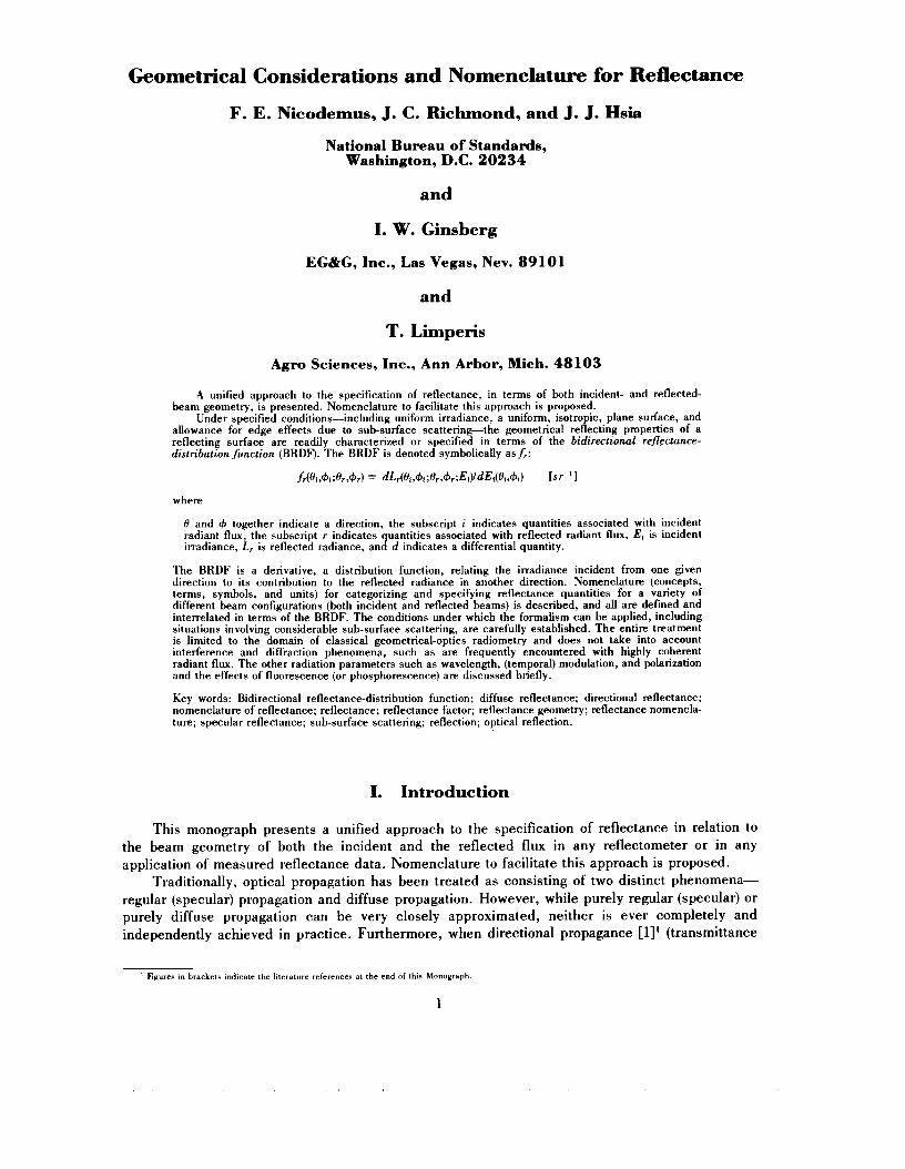
A unified approach to the specification of reflectance, in terms of both incident- and reflected- beam geometry, is presented. Nomenclature to facilitate this approach is proposed.
Under specified conditions-including uniform irradiance, a uniform, isotropic, plane surface, and allowance for edge effects due to sub-surface scattering-the geometrical reflecting properties of a reflecting surface are readily characterized or specified in terms of the bidirectional reflectance- distribution function (BRDF). The BRDF is denoted symbolically asfr:
f(H, ,+, ; H , , + J = dL,(O,,+, ;H,,+,;E,YdE,(H,,+d [s r-'I
where
H and $J together indicate a direction, the subscript i indicates quantities associated with incident radiant flux, the subscript r indicates uantities associated with reflected radiant flux, E, is incident irradiance, L, is reflected radiance, an] d indicates a differential quantity.
The BRDF is a derivative, a distribution function, relating the irradiance incident from one given direction to its contribution to the reflected radiance in another direction. Nomenclature (concepts, terms, symbols, and units) for categorizing and specifying reflectance quantities for a variety of different beam configurations (both incident and reflected beams) is described, and all are defined and interrelated in terms of the BRDF. The conditions under which the formalism can be applied, including situations involving considerable sub-surface scattering, are carefully established. The entire treatment is limited to the domain of classical geometrical-optics radiometry and does not take into account interference and diffraction phenomena, such as are frequently encountered with highly coherent radiant flux. The other radiation parameters such as wavelength, (temporal) modulation, and polarization and the effects of fluorescence (or phosphorescence) are discussed briefly.
Key words: Bidirectional reflectance-distribution function; diffuse reflectance; directional reflectance; nomenclature of reflectance; reflectance; reflectance factor; reflectance geometry; reflectance nomencla- ture; specular reflectance; sub-surface scattering; reflection; optical reflection.
I. Introduction
This monograph presents a unified approach to the specification of reflectance in relation to the beam geometry of both the incident and the reflected flux in any reflectometer or in any application of measured reflectance data. Nomenclature to facilitate this approach is proposed.
Traditionally, optical propagation has been treated as consisting of two distinct phenomena- regular (specular) propagation and diffuse propagation. However, while purely regular (specular) or purely diffuse propagation can be very closely approximated, neither is ever completely and independently achieved in practice. Furthermore, when directional propagance [l]' (transmittance
' Figures in brackets indicate the literature references at the end of this Monograph.
1
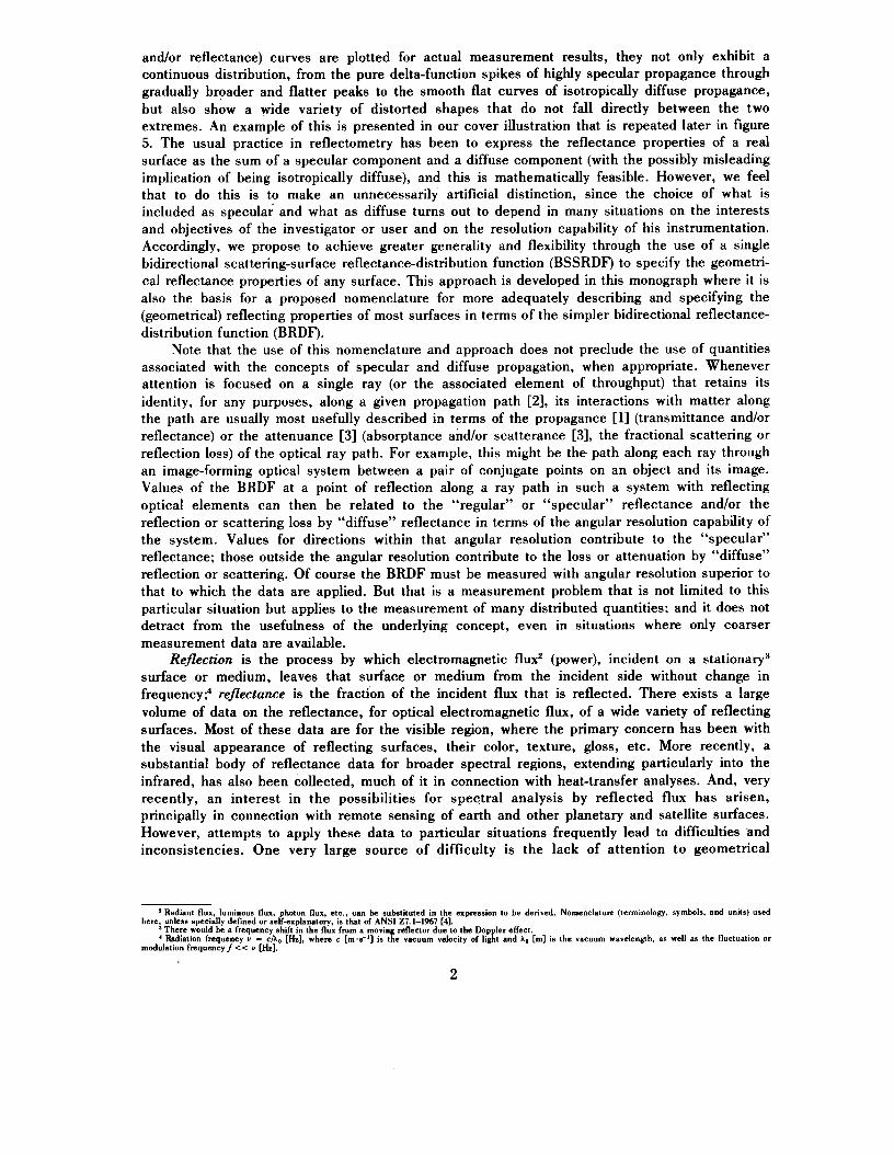
and/or reflectance) curves are plotted for actual measurement results, they not only exhibit a continuous distribution, from the pure delta-function spikes of highly specular propagance through gradually broader and flatter peaks to the smooth flat curves of isotropically diffuse propagance, but also show a wide variety of distorted shapes that do not fall directly between the two extremes. An example of this is presented in our cover illustration that is repeated later in figure 5. The usual practice in reflectometry has been to express the reflectance properties of a real surface as the sum of a specular component and a diffuse component (with the possibly misleading implication of being isotropically diffuse), and this is mathematically feasible. However, we feel that to do this is to make an unnecessarily artificial distinction, since the choice of what is included as specular and what as diffuse turns out to depend in many situations on the interests and objectives of the investigator or user and on the resolution capability of his instrumentation. Accordingly, we propose to achieve greater generality and flexibility through the use of a single bidirectional scattering-surface reflectance-distribution function (BSSRDF) to specify the geometri- cal reflectance properties of any surface. This approach is developed in this monograph where it is also the basis for a proposed nomenclature for more adequately describing and specifying the (geometrical) reflecting properties of most surfaces in terms of the simpler bidirectional reflectance- distribution function (BRDF).
Note that the use of this nomenclature and approach does not preclude the use of quantities associated with the concepts of specular and diffuse propagation, when appropriate. Whenever attention is focused on a single ray (or the associated element of throughput) that retains its identity, for any purposes, along a given propagation path [2], its interactions with matter along the path are usually most usefully described in terms of the propagance [l] (transmittance and/or reflectance) or the attenuance [3] (absorptance and/or scatterance [3], the fractional scattering or reflection loss) of the optical ray path. For example, this might be the path along each ray through an image-forming optical system between a pair of conjugate points on an object and its image. Values of the BRDF at a point of reflection along a ray path in such a system with reflecting optical elements can then be related to the “regular” or “specular” reflectance and/or the reflection or scattering loss by “diffuse” reflectance in terms of the angular resolution capability of the system. Values for directions within that angular resolution contribute to the “specular” reflectance; those outside the angular resolution contribute to the loss or attenuation by “diffuse” reflection or scattering. Of course the BRDF must be measured with angular resolution superior to that to which the data are applied. But that is a measurement problem that is not limited to this particular situation but applies to the measurement of many distributed quantities; and it does not detract from the usefulness of the underlying concept, even in situations where only coarser measurement data are available.
Reflection is the process by which electromagnetic flux2 (power), incident on a stationary3 surface or medium, leaves that surface or medium from the incident side without change in frequencyP reflectance is the fraction of the incident flux that is reflected. There exists a large volume of data on the reflectance, for optical electromagnetic flux, of a wide variety of reflecting surfaces. Most of these data are for the visible region, where the primary concern has been with the visual appearance of reflecting surfaces, their color, texture, gloss, etc. More recently, a substantial body of reflectance data for broader spectral regions, extending particularly into the infrared, has also been collected, much of it in connection with heat-transfer analyses. And, very recently, an interest in the possibilities for spectral analysis by reflected flux has arisen, principally in connection with remote sensing of earth and other planetary and satellite surfaces. However, attempts to apply these data to particular situations frequently lead to difficulties and inconsistencies. One very large source of difficulty is the lack of attention to geometrical
a Radiant flux, luminous flux, photon flux, etc., can be substituted in the expression to be derived. Nomenclature (terminology, symbols, and units) used
‘ Radiation frequency Y = cA. [Hzl, where c [m,s-’] is the vacuum velocity of light and io [m] is the vacuum wavelength. as well as the fluctuation or
here. unless specially defined or self-explanatory. is that of ANSI 27.1-1%7 [41.
modulation frequency/ << Y [Hzl.
There would be a frequency shift in the flux from a moving reflector due to the Doppler effect.
2
parameters, both for beams of incident flux and for beams in which reflected flux is collected and detected. In fact, most optics texts fail to provide adequate nomenclature (terms andlor symbols) for clearly designating and discussing these geometrical considerations. A unified approach to geometrical-reflectance and related nomenclature is proposed in this monograph.
Transmission, absorption, spectral and polarization effects, and fluorescence, essential considerations for any complete treatment of reflectance [5], are not treated here. It should also be emphasized that we are concerned only with geometrical (ray) optics; it is assumed that there is no significant interference or diffraction. With the explosive increase in the use of coherent laser flux, situations involving these phenomena of physical (wave) optics are becoming increasingly important. Accordingly, it should be emphasized that the quantities and relationships developed in this paper should not be blindly applied to situations involving lasers. They may only be used when it has been verified that, in fact, the basic assumptions of geometrical optics do apply to an adequate degree of approximation. Those assumptions are discussed in [6] and [7].
The remainder of this monograph is organized into four sections, in order to present first the principal approach and then some variations on that approach and some related details. The main ideas proposed by the authors are presented in section 11. The bidirectional reflectance-distribution function (BRDF) and reflectance concepts as well as the basic set of reflectance nomenclature are formalized. Section 111 deals with some possibilities for additional reflectance quantities and nomenclature. Practical considerations for measurement of reflectance quantities and nomencla- ture are discussed in section IV. Section V concludes with a summary and recommendations. In addition, there are four appendices. Appendix A is a brief historical review of how we came to write this monograph and what transpired while it took so long to complete and publish it. It also gives the reasons for some of our choices of nomenclature. Appendix B describes a thought experiment that some may find helpful in trying to understand the concept of the BRDF. The expressions for perfectly diffuse and perfectly specular (regular) reflection are derived and discussed in appendix C and the latter is also extended to off-specular peaks or “glints.” The last appendix, appendix D, presents the detailed derivations of some important relations in McCamy’s notation.
11. Reflectance Concepts and Nomenclature
In order to simplify the development of concepts and formalization of nomenclature, we first study a model in which a relatively large area of reflecting surface is irradiated by a well- collimated beam of incident radiation, examining the radiation reflected from a point well within the irradiated area. Here, we confine our attention to geometrical considerations, to the effects of just the spatial parameters of position and direction of all rays. Important effects of the other radiation parameters-the spectral parameter (wawlength, frequency Y, or wave number), the temporal parameter (time, or fluctuation or modulation frequency f << v), and the polarization pa rame teds t and of fluorescence (or phosphorescence) are briefly discussed in section 1V.E.
A. Bidirectional Reflectance-Distribution Function (BRDF)
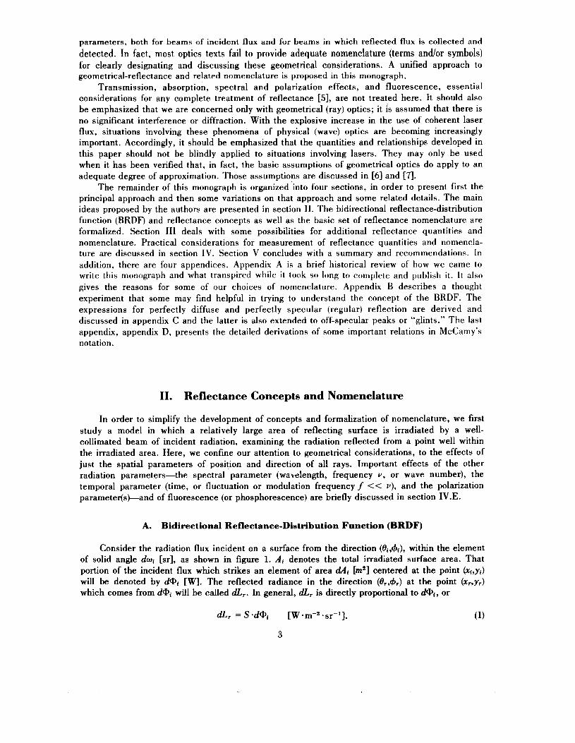
Consider the radiation flux incident on a surface from the direction (Oi ,$i) , within the element of solid angle dwi [sr], as shown in figure 1. Ai denotes the total irradiated surface area. That portion of the incident flux which strikes an element of area dAi [m23 centered at the point (xi,yi) will be denoted by d@j [W]. The reflected radiance in the direction (Or,+,) at the point (xrtyr) which comes from d@i will be called dL,. In general, dLr is directly proportional to d@i, or
dLr = S . d a i [W *ST-’].
3
SAMPLE SURFACE
IRRADIATED AREA, A / FIGURE 1. Geometry of inciaknt and reflected beams (for general cases where sub-surface Scattering is involved).
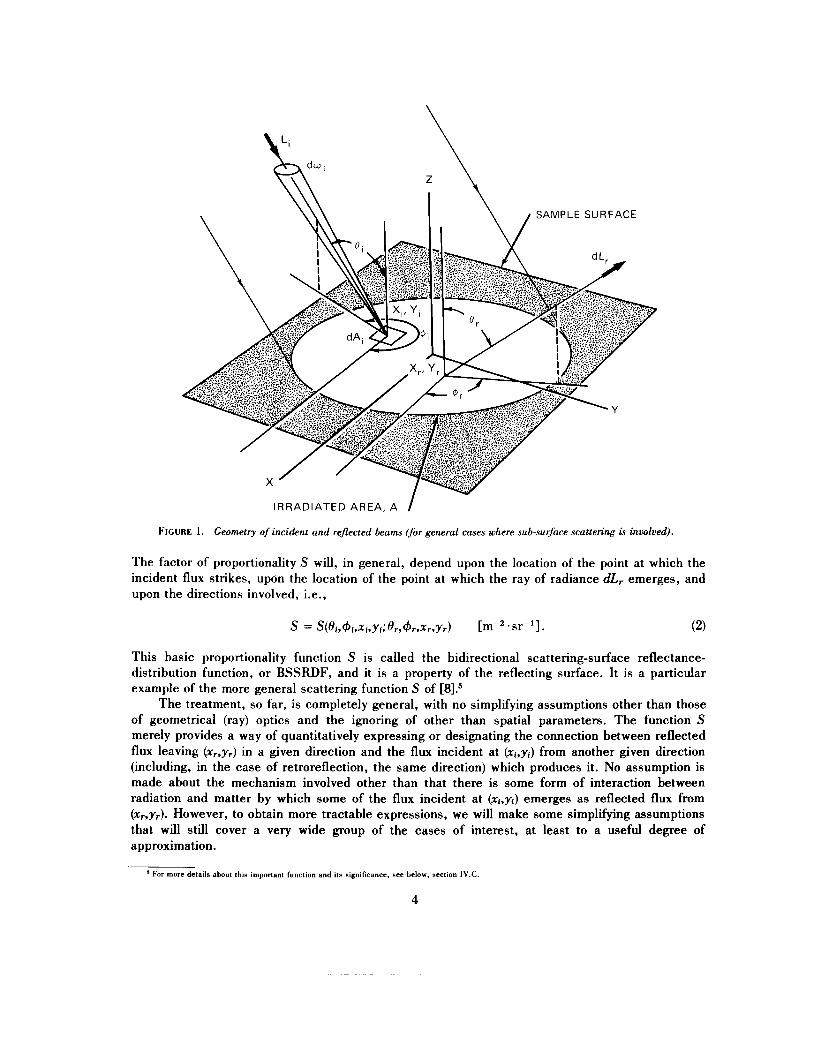
The factor of proportionality S will, in general, depend upon the location of the point at which the incident flux strikes, upon the location of the point at which the ray of radiance dLr emerges, and upon the directions involved, i.e.,
This basic proportionality function S is called the bidirectional scattering-surface reflectance- distribution function, or BSSRDF, and it is a property of the reflecting surface. It is a particular example of the more general scattering function S of [8].5
The treatment, so far, is completely general, with no simplifying assumptions other than those of geometrical (ray) optics and the ignoring of other than spatial parameters. The function S merely provides a way of quantitatively expressing or designating the connection between reflected flux leaving (x,.,yr) in a given direction and the flux incident at (xr,yi) from another given direction (including, in the case of retroreflection, the same direction) which produces it. No assumption is made about the mechanism involved other than that there is some form of interaction between radiation and matter by which some of the flux incident at (zr,yi) emerges as reflected flux from (xr,Yr). However, to obtain more tractable expressions, we will make some simplifying assumptions that will still cover a very wide group of the cases of interest, at least to a useful degree of approximation.
' For more details ahout this important function and its significance, see below, section 1V.C
4

A convenient flat surface is chosen as a reference plane to represent the reflecting surface, instead of attempting to describe and deal with its surface contours in microscopic detail. Then the polar angles 8 are angles from the reference-plane normal, and azimuth angles 4 are angles from an arbitrary reference direction in the reference plane. It is also assumed that the surface is uniformly irradiated over the entire part of the area Ai from which there is a significant contribution to the reflected radiance at (xr,yr), i.e., the incident radiance depends only on direction:
The incident flux dQi on the element of area dAi [from just the solid-angle element dwi in the direction ( O j & ) ] is
where dEi [= Li-cosOj*dwi] is the incident irradiance and dwi is the solid-angle element within which the incident radiance is confined. We can add up the contributions to the reflected radiance at (xr,yr) from the entire incident flux in the direction (Oj,+i) and within the solid-angle element dwi by integrating dLr [eq (l)] over the entire irradiated area:
If we further assume that the scattering properties of the sample are uniform and isotropic across the reference plane, the scattering function S does not depend on the location of the point of observation (x,,yr), but it still depends on the distance r between (xi,yJ and (xr,yr). Equation (5) can now be written as
where
and
r = [(xr-xi)' + (yr-yi)'3f. (8)
Thus, for uniform irradiance over a large enough area of a uniform and isotropic surface, the basic quantity that characterizes (geometrically) the reflecting properties of that surface is the function f r :
5
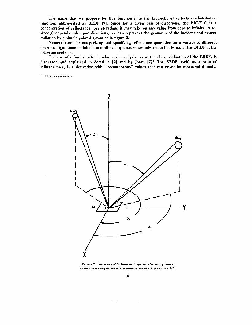
The name that we propose for this function fr is the bidirectional reflectance-distribution function, abbreviated as BRDF [9]. Since for a given pair of directions, the BRDF fr is a concentration of reflectance (per steradian) it may take on any value from zero to infinity. Also, sincef, depends only upon directions, we can represent the geometry of the incident and exitemt radiation by a simple polar diagram as in figure 2.
Nomenclature for categorizing and specifying reflectance quantities for a variety of different beam configurations is defined and all such quantities are interrelated in terms of the BRDF in the following sections.
The use of infinitesimals in radiometric analysis, as in the above definition of the BRDF, is discussed and explained in detail in [2] and by Jones [7].6 The BRDF itself, as a ratio of infinitesimals, is a derivative with “instantaneous” values that can never be measured directly.
See, also. section 1V.A.
Z
X FIGURE 2. Geometry of incident and rejlected ekmentary beams.
(Z-Axis is chosen along the normal to the surface element dA at 0.) (adapted fmm [IO]).
6
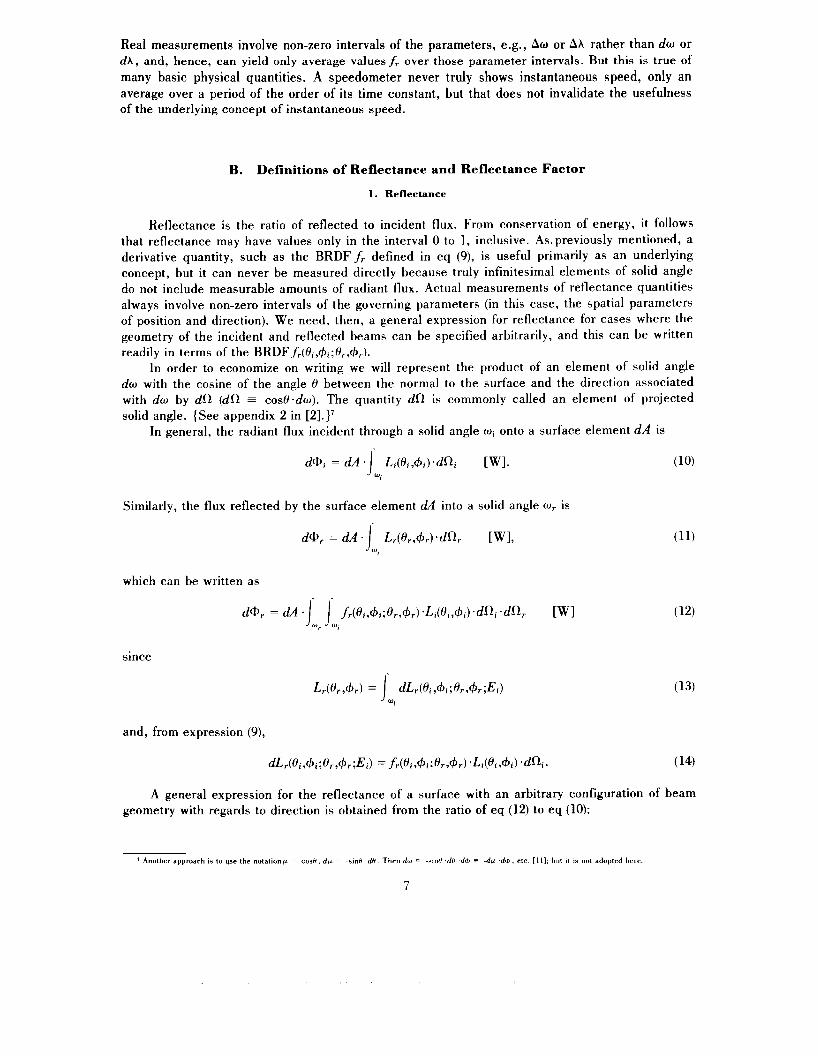
Real measurements involve non-zero intervals of the parameters, e.g., Aw or Ah rather than dw or dA, and, hence, can yield only average valuesf, over those parameter intervals. But this is true of many basic physical quantities. A speedometer never truly shows instantaneous speed, only an average over a period of the order of its time constant, but that does not invalidate the usefulness of the underlying concept of instantaneous speed.
B. Definitions of Reflectance and Reflectance Factor
1. Reflectance
Reflectance is the ratio of reflected to incident flux. From conservation of energy, it follows that reflectance may have values only in the interval 0 to 1, inclusive. As.previously mentioned, a derivative quantity, such as the BRDFf, defined in eq (9), is useful primarily as an underlying concept, but it can never be measured directly because truly infinitesimal elements of solid angle do not include measurable amounts of radiant flux. Actual measurements of reflectance quantities always involve non-zero intervals of the governing parameters (in this case, the spatial parameters of position and direction). We need, then, a general expression for reflectance for cases where the geometry of the incident and reflected beams can be specified arbitrarily, and this can be written readily in terms of the BRDFfr(Oi,+,;8,,+,).
In order to economize on writing we will represent the product of an element of solid angle dw with the cosine of the angle 8 between the normal to the surface and the direction associated with dw by dR (dR = cosO.dw). The quantity dR is commonly called an element of projected solid angle. {See appendix 2 in [2].}'
In general, the radiant flux incident through a solid angle wi onto a surface element dA is
Similarly, the flux reflected by the surface element dA into a solid angle wr is
dQr = d~ .J L r ( o r , + r ) . d f i r [WI, wr
which can be written as
since
(11)
and, from expression (9),
A general expression for the reflectance of a surface with an arbitrary configuration of beam geometry with regards to direction is obtained from the ratio of eq (12) to eq (10):
' Another approach IS lo use the notationfi = eosH, dfi = - s m H .dH. Then dw -sinH .dH .dd> - -dfi .dd , etc. [ll]: hut 11 IS not adopted her?
7
J Li(ei,+i)*dai "i
[dimensionless]. (15a)
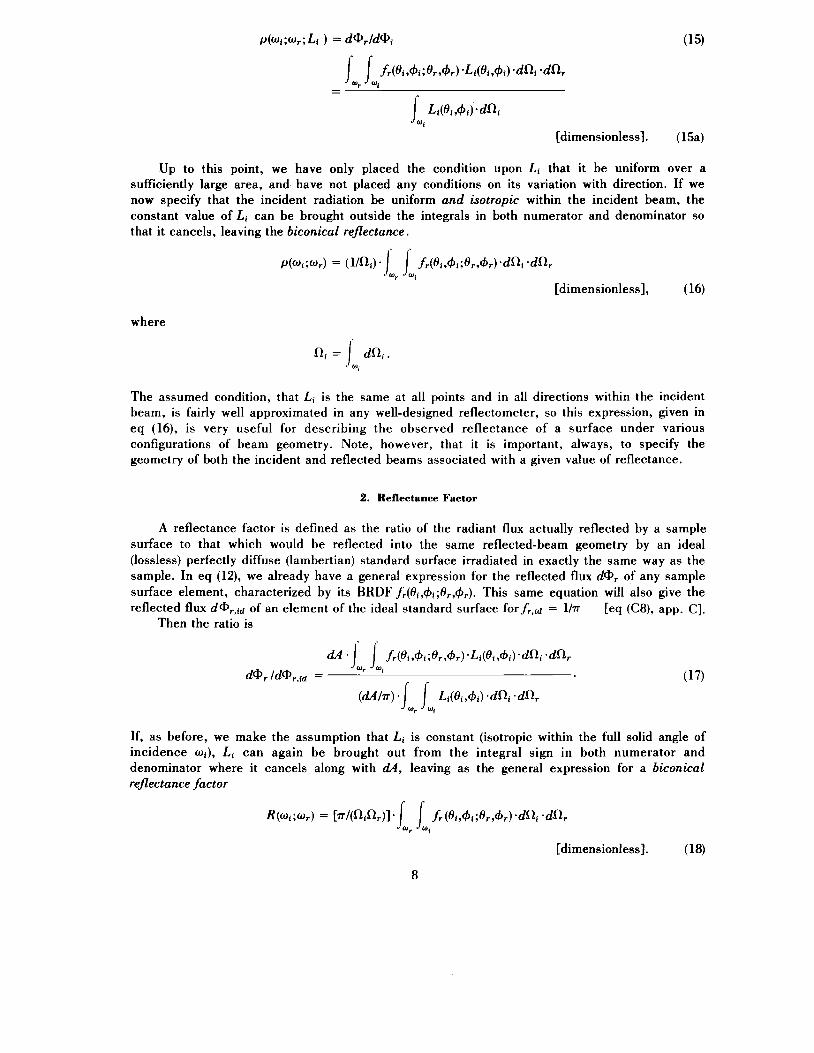
Up to this point, we have only placed the condition upon Li that it be uniform over a sufficiently large area, and have not placed any conditions on its variation with direction. If we now specify that the incident radiation be uniform and isotropic within the incident beam, the constant value of Li can be brought outside the integrals in both numerator and denominator so that it cancels, leaving the biconical reflectance.
~. P ( u i ; W r ) = (1/ni)* J J fr(ei,+i;er,+r).dni .dRr
"r
[dimensionless], (16)
where
Sli = J dSli. Wi
The assumed condition, that Li is the same at all points and in all directions within the incident beam, is fairly well approximated in any well-designed reflectometer, so this expression, given in eq (16), is very useful for describing the observed reflectance of a surface under various configurations of beam geometry. Note, however, that it is important, always, to specify the geometry of both the incident and reflected beams associated with a given value of reflectance.
2. Reflectance Factor
A reflectance factor is defined as the ratio of the radiant flux actually reflected by a sample surface to that which would be reflected into the same reflected-beam geometry by an ideal (lossless) perfectly diffuse (lambertian) standard surface irradiated in exactly the same way as the sample. In eq (12), we already have a general expression for the reflected flux dQr of any sample surface element, characterized by its BRDF fr(/3i,+i;flr,+r). This same equation will also give the reflected flux dQr,id of an element of the ideal standard surface for fr,id = lh [eq (C8), app. C].
Then the ratio is
0~ . Ji, J~i f r (" ,Qi ;e r ,Qr ) .L i ( e i ,Q i ) .dR , .dRr
(dA/n) *I Li(@i,Qi) *dQ .dRr dQr /dQr,id = (17)
wr wi
If, as before, we make the assumption that Li is constant (isotropic within the full solid angle of incidence mi), Li can again be brought out from the integral sign in both numerator and denominator where it cancels along with dA, leaving as the general expression for a biconical reflectance factor
R(wi;or) = [ ~ / ( Q f l r ) l * / fr(ei,+i;er,+r)*dQ .dRr wr "i
[dimensionless]. (18)
8
In some cases, the use of the reflectance factor is preferred over the use of reflectance. For example, in the case of almost lambertian reflectors, the reflectance factor R is nearly independent of beam orientations, thereby making the reflectance factor a particularly attractive quantity to use in describing such reflectors.
C. Reflectances and Reflectance Factors for Nine Geometries
1. Reflectances for Nine Geometries
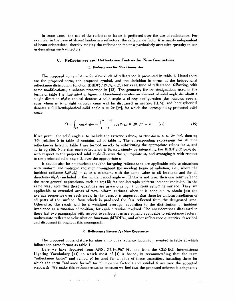
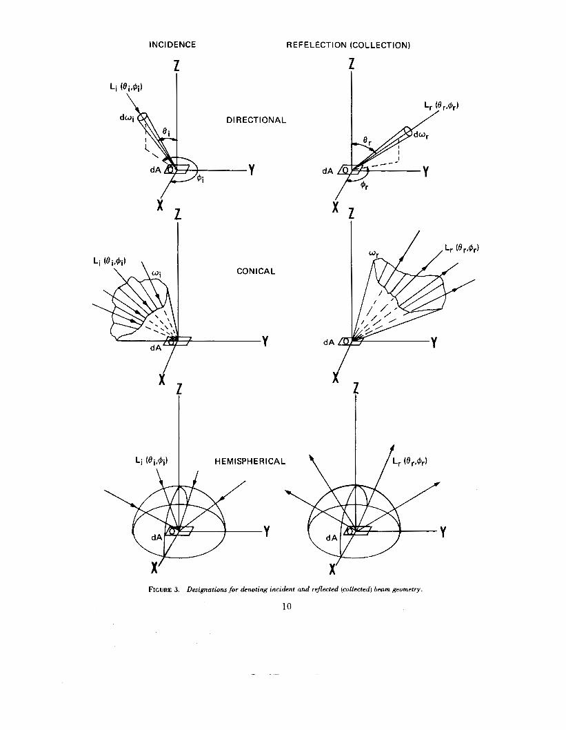
The proposed nomenclature for nine kinds of reflectance is presented in table 1. Listed there are the proposed term, the proposed symbol, and the definition in terms of the bidirectional reflectance-distribution function (BRDF) fr(Oi,+i;Or,+r) for each kind of reflectance, following, with some modifications, a scheme presented in [12]. The geometry for the designations used in the terms of table 1 is illustrated in figure 3. Directional denotes an element of solid angle do about a single direction (O,+); conical denotes a solid angle w of any configuration (the common special case where w is a right circular cone will be discussed in section 1II.A); and hemispherical denotes a full hemispherical solid angle w = 27r [sr], for which the corresponding projected solid angle
If we permit the solid angle w to include the extreme values, so that do 5 w 5 27r [srl, then eq (16) (relation 5 in table 1) contains all of table 1. The corresponding expressions for all nine reflectances listed in table 1 are formed merely by substituting the appropriate values for wi and or in eq (16). Note that each reflectance is formed simply by integrating the BRDFfr(oi,+i;or,+r) with respect to the projected solid angle a, over the appropriate w, and averaging it with respect to the projected solid angle 52, over the appropriate wi.
It should also be emphasized that the foregoing reflectances are applicable only to situations with uniform and isotropic radiation throughout the incident beam of radiation; i.e., where the incident radiance Li(Oi,+i) = Li is a constant, with the same value at all locations and for all directions (Oi,+i) included in the incident solid angle wi. If this is not true, then one must refer to the more general expressions, such as eq (15) for non-isotropic uniform incident radiation. In the same way, note that these quantities are given only for a uniform reflecting surface. They are applicable to extended areas of non-uniform surfaces when it is adequate to obtain just the average properties over such areas. In this case, it is important that there be uniform irradiation of all parts of the surface, from which is produced the flux reflected from the designated area. Otherwise, the result will be a weighted average, according to the distribution of incident irradiance as a function of position, for each direction involved. The considerations discussed in these last two paragraphs with respect to reflectances are equally applicable to reflectance factors, multivariate reflectance-distribution functions (MRDFs), and other reflectance quantities described and discussed throughout this monograph.
2. Reflectance Factors for Nine Geometries
The proposed nomenclature for nine kinds of reflectance factor is presented in table 2, which follows the same format as table 1.
Here we have departed from ANSI 27.1-1967 [4], and from the CIEIEC International Lighting Vocabulary [14] on which most of [4] is based, in recommending that the term “reflectance factor” and symbol R be used for all nine of these quantities, including three for which the term “radiance factor” (or “luminance factor”) and symbol p are now the accepted standards. We make this recbmmendation because we feel that the proposed scheme is adequately
9
INCIDENCE R E F E L ECTl ON (COLLECT ION)
Z 2
X Z
'IONAL
X
CON I CAL
dA L[T
i J
Y
FIGURE 3. Designations for denoting incident and ref2ected (collected) beam geometry.
10
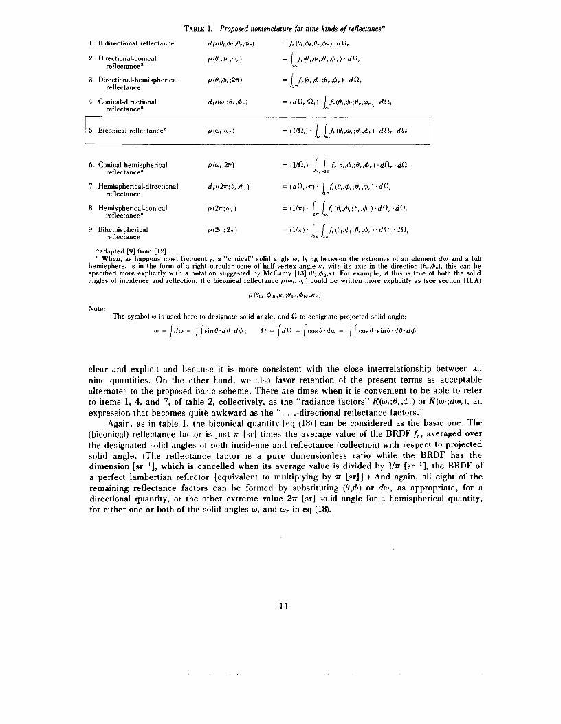
TABLE 1. Proposed nomenclature for nine kinds of reflectance;
1. Bidirectional reflectance dP(Hi,+i ;%A) fr(&y+l;f)r&r) ‘ dfA
2. Directional-conical reflectancea
9. Bihemispherical reflectance
*adapted [9] from [12]. a When, as happens most frequently, a “conical” solid angle w , lying between the extremes of an element d w and a full
hemisphere, is in the form of a right circular cone of half-vertex angle K , with its axis in the direction ( I Y ~ , + ~ ) , this can be specified more explicitly with a notation suggested by McCamy [13] ( H 0 , + , , , ~ ) . For example, if this is true of both the solid angles of incidence and reflection, the biconical reflectance p ( w c ; w r ) could be written more explicitly as (see section 1II.A)
P (%i ,40t A ; % r , 4 w , ~ r ) Note:
The symbol w is used here to designate solid angle, and 12 to designate projected solid angle:
clear and explicit and because it is more consistent with the close interrelationship between all nine quantities. On the other hand, we also favor retention of the present terms as acceptable alternates to the proposed basic scheme. There are times when it is convenient to be able to refer to items 1, 4, and 7, of table 2, collectively, as the “radiance factors” R(wi;O,,+,) or R(w,;dwr), an expression that becomes quite awkward as the “. . .-directional reflectance factors.”
Again, as in table 1, the biconical quantity [eq (18)] can be considered as the basic one. The (biconical) reflectance factor is just 7r [sr] times the average value of the BRDFf,, averaged over the designated solid angles of both incidence and reflectance (collection) with respect to projected solid angle. (The reflectance factor is a pure dimensionless ratio while the BRDF has the dimension [sr-’1, which is cancelled when its average value is divided by lhr [sr-l], the BRDF of a perfect lambertian reflector {equivalent to multiplying by 7r [sr]}.) And again, all eight of the remaining reflectance factors can be formed by substituting (e,+) or dw, as appropriate, for a directional quantity, or the other extreme value 27r [sr] solid angle for a hemispherical quantity, for either one or both of the solid angles wi and w, in eq (18).
11
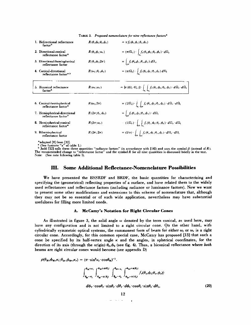
TABLE 2. Proposed nomenclature for nine reflectance factors*
1. Bidirectional reflectance R (oi.4i;or.4r) = wfr(ol74I;or,4r) factorb
reflectance factor’ W,
reflectance factor
2. Directional-conical R (01941 ;wr) = (r/nr) 1 jr(oiv4l;or*4r.)
3. Directional-hemispherical R (el ; 2 ~ ) = l /(ot/#J<;orv@r)
4. Conical-directional R ( 0 1 ;or A) reflectance factor’sb
6. Conical-hemispherical R(w,;W = ( l / W ] 1 f,(el,+,;H,,+,).dR,.dR, 7. Hemispherical-directional R Gkor,4,) = J*Jr(o#.+t;or.4r)~ d o ,
8. Hemispherical-conical R(27cwr) = (” 1 J f i (H , ,+ , ;o , ,+ , ) .dn, .dni
9. Bihemispherical R(27r ;2r ) = ( l /w)’ ln l f , ( e , , + , ; H , , + , ) . d ~ ~ , . d ~ ~ i
reflectance factor’ wi n
reflectance factorb
reflectance factor’ n w,
reflectance factor n
*adapted 191 from [121. a (See footnote “a” of table 1.)
Judd [121 calls these three quantities “radiance factors” (in accordance with [14]) and uses the symbol p (instead of R ) . The recommended change to “reflectance factor” and the symbol R for all nine quantities is discussed briefly in the text. Note: (See note following table 1).
111. Some Additional Reflectance-Nomenclature Possibilities
We have presented the BSSRDF and BRDF, the basic quantities for characterizing and specifying the (geometrical) reflecting properties of a surface, and have related them to the widely used reflectances and reflectance factors (including radiance or luminance factors). Now we want to present some other modifications and extensions to this scheme of nomenclature that, although they may not be so essential or of such wide application, nevertheless may have substantial usefulness for filling more limited needs.
A. McCamy’s Notation for Right Circular Cones
As illustrated in figure 3, the solid angle o denoted by the term conical, as used here, may have any configuration and is not limited to a right circular cone. On the other hand, with cylindrically symmetric optical systems, the commonest form of beam for either or o r is a right circular cone. Accordingly, for this common special case, McCamy has proposed [13] that such a cone be specified by its half-vertex angle K and the angles, in spherical coordinates, for the direction of its axis (through the origin) O0,+, (see fig. 4). Thus, a biconical reflectance where both beams are right circular cones would become (see appendix D)

\ \ \ \
/ 1
/ /
Y
X FIGURE 4. McCamy's notation for right+ircular cones.
where
a(O) = COS-*[(COSK - cosOo .cosO)/(sinOo*sinO)]. (21)
A similar expression can be written for the biconical reflectance factor, or for any conical reflectance quantity, where the beam is a right circular cone.
13
where, as before, a(0) is given by eq (21).
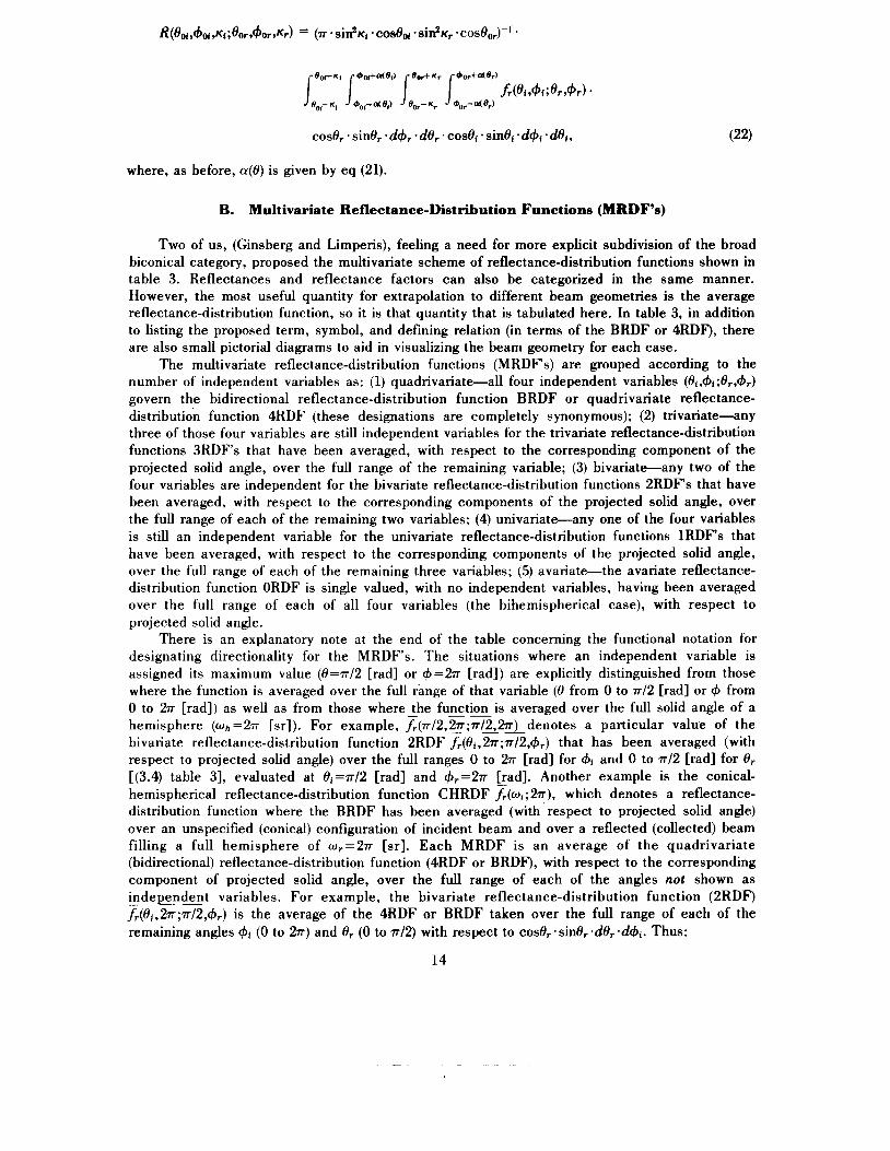
B. Multivariate Reflectance-Distribution Functions (MRDF's)
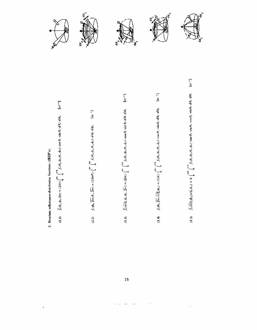
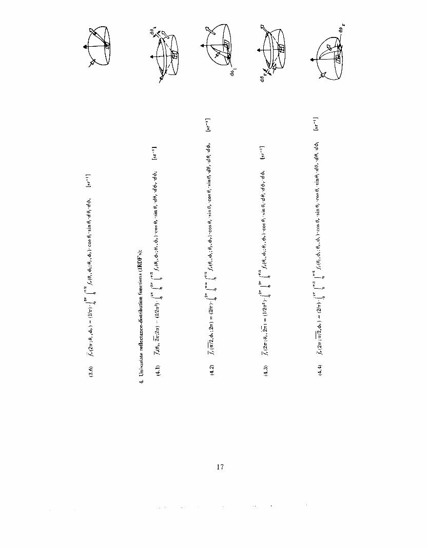
Two of us, (Ginsberg and Limperis), feeling a need for more explicit subdivision of the broad biconical category, proposed the multivariate scheme of reflectancedistribution functions shown in table 3. Reflectances and reflectance factors can also be categorized in the same manner. However, the most useful quantity for extrapolation to different beam geometries is the average reflectance-distribution function, so it is that quantity that is tabulated here. In table 3, in addition to listing the proposed term, symbol, and defining relation (in terms of the BRDF or 4RDF), there are also small pictorial diagrams to aid in visualizing the beam geometry for each case.
The multivariate reflectance-distribution functions (MRDFs) are grouped according to the number of independent variables as: (1) quadrivariate-all four independent variables (Oi,4i;Or,&) govern the bidirectional reflectance-distribution function BRDF or quadrivariate reflectance- distribution function 4RDF (these designations are completely synonymous); (2) trivariate-any three of those four variables are still independent variables for the trivariate reflectance-distribution functions 3RDFs that have been averaged, with respect to the corresponding component of the projected solid angle, over the full range of the remaining variable; (3) bivariate-any two of the four variables are independent for the bivariate reflectance-distribution functions 2RDF's that have been averaged, with respect to the corresponding components of the projected solid angle, over the full range of each of the remaining two variables; (4) univariate-any one of the four variables is still an independent variable for the univariate reflectance-distribution functions 1RDF's that have been averaged, with respect to the corresponding components of the projected solid angle, over the full range of each of the remaining three variables; (5) avariate-the avariate reflectance- distribution function ORDF is single valued, with no independent variables, having been averaged over the full range of each of all four variables (the bihemispherical case), with respect to projected solid angle.
There is an explanatory note at the end of the table concerning the functional notation for designating directionality for the MRDFs. The situations where an independent variable is assigned its maximum value (0=7~/2 [rad] or 4 = 2 ~ [rad]) are explicitly distinguished from those where the function is averaged over the full range of that variable (e from 0 to 77/2 [rad] or 4 from 0 to 277 [rad]) as well as from those where - the function -- is averaged over the full solid angle of a hemisphere (wh =277 [sr]). For example, fr(77/2,@;77/2,27r) denotes a particular value of the bivariate reflectance-distribution function 2RDF fr(8i,27r;77/2,4r) that has been averaged (with respect to projected solid angle) over the full ranges 0 to 277 [rad] for $i and 0 to 77/2 [rad] for Or r(3.4) table 31, evaluated at ei=7r/2 [rad] and 4,=277 [rad]. Another example is the conical- hemispherical reflectance-distribution function CHRDF %(mi; 277), which denotes a reflectance- distribution function where the BRDF has been averaged (with respect to projected solid angle) over an unspecified (conical) configuration of incident beam and over a reflected (collected) beam filling a full hemisphere of wr=277 [sr]. Each MRDF is an average of the quadrivariate (bidirectional) reflectance-distribution function (4RDF or BRDF), with respect to the corresponding component of projected solid angle, over the full range of each of the angles not shown as independent _ _ variables. For example, the bivariate reflectance-distribution function (2RDF) Z(8,,27r;7r/2,4,) is the average of the 4RDF or BRDF taken over the full range of each of the remaining angles 4i (0 to 277) and Or (0 to 77/2) with respect to cose,.sinOr.dOr.d4i. Thus:
14

- - I L
Y
- - I c Y
a- ? a' c .- m
m 0 P
3 - I c m Y
6 ?
II
- .- , L
Y
c9- -? a- E .- Lo
a"
a ..
N k
'7 N
15
n - I
m Y
0' P 0' a 0' e .- m
-6 a 0' a
s' a c - I
m v d a 6- e .- m
6-
0" C .- m
0"
0 Q
m
- m u e:
m
N
c
c '-0
9- N - c '- d
- P 3
- P 3 - II
1
II II
k I N.
16
I
m v
B P 6- P 6- C .- m
I c m v
d
I
m Y
&-
I-' m 0
0" C .- Lo
b
"y k
II B
n - I c Lo v
B P P s'
I; "_, t N
II
lk
n - I
Lo v
9
P 9 C .- Lo
6-
I-' Lo 0
9' E: .- Lo
0'
17

Pj- 7, 0' 7, Pj- E .- m
Pj- m 0
0" E .- m
0" m
I.'
18
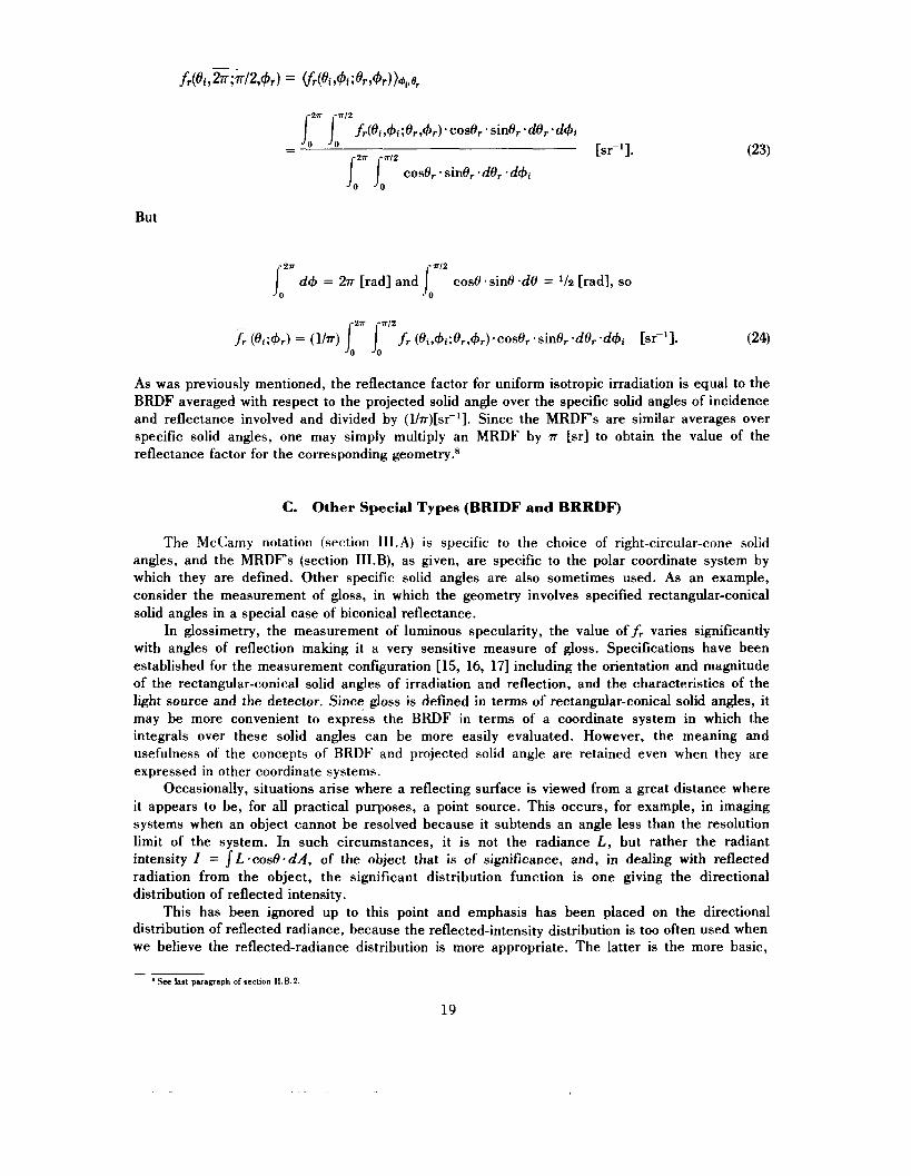
But
IozT d+ = 27r [rad] and cos0 .sin0 -de = 1/2 [rad], so j0="
As was previously mentioned, the reflectance factor for uniform isotropic irradiation is equal to the BRDF averaged with respect to the projected solid angle over the specific solid angles of incidence and reflectance involved and divided by (l/.rr)[sr-']. Since the MRDFs are similar averages over specific solid angles, one may simply multiply an MRDF by 7r [sr] to obtain the value of the reflectance factor for the corresponding geometry.*
C. Other Special Types (BRIDF and BRRDF)
The McCamy notation (section 1II.A) is specific to the choice of right-circular-cone solid angles, and the MRDF's (section III.B), as given, are specific to the polar coordinate system by which they are defined. Other specific solid angles are also sometimes used. As an example, consider the measurement of gloss, in which the geometry involves specified rectangular-conical solid angles in a special case of biconical reflectance.
In glossimetry, the measurement of luminous specularity, the value of fr vanes significantly with angles of reflection making it a very sensitive measure of gloss. Specifications have been established for the measurement configuration [15, 16, 171 including the orientation and magnitude of the rectangular-conical solid angles of irradiation and reflection, and the characteristics of the light source and the detector. Since gloss is defined in terms of rectangular-conical solid angles, it may be more convenient to express the BRDF in terms of a coordinate system in which the integrals over these solid angles can be more easily evaluated. However, the meaning and usefulness of the concepts of BRDF and projected solid angle are retained even when they are expressed in other coordinate systems.
Occasionally, situations arise where a reflecting surface is viewed from a great distance where it appears to be, for all practical purposes, a point source. This occurs, for example, in imaging systems when an object cannot be resolved because it subtends an angle less than the resolution limit of the system. In such circumstances, it is not the radiance L, but rather the radiant intensity Z = SL.*cose.dA, of the object that is of significance, and, in dealing with reflected radiation from the object, the significant distribution function is one giving the directional distribution of reflected intensity.
This has been ignored up to this point and emphasis has been placed on the directional distribution of reflected radiance, because the reflected-intensity distribution is too often used when we believe the reflected-radiance distribution is more appropriate. The latter is the more basic,
See last paragraph of section II.B.2
19

because, when the radiance is known, the intensity can always be obtained from it as I = SAL case * dA [W * ST-’], while the reverse is not true. Given only the intensity I, this integral equation cannot be solved for the radiance L without more information about its distribution over the radiating (emitting and/or reflecting) surface in question.
When it is necessary to distinguish between these two reflectance-distribution functions (RDFs), the following terminology and notation may be used. The bidirectional reflected-radiance- distributionfunction (BRRDF), which we have been calling just the BRDF up to this point?
while the bidirectional reflected-intensitydistribution function (BRIDF) is
DeVos calls this quantity the “partial reflectance” r“ [19]. For a surface element dA, small enough so that there is no significant variation of radiance L across its surface, it is easily shown that
It may also be useful to express reflectances and reflectance factors in terms of the BRIDFf,,. As we have seen, it is. adequate to have just the expression for the biconical quantity, since the other eight follow readily from it, in each case. The biconical reflectance, then, is
and the corresponding biconical reflectance factor is
The BRIDF also figures prominently in an ingenious approach to modelling the reflectance of any rough surface in terms of an equivalent, single, optically smooth, curved surface of revolution, by Trowbridge and Reitz [20].
In the balance of this monograph, and elsewhere, we will continue the practice of using the simpler nomenclature bidirectionul reflectancedistribution function (BRDF) f,(Oi,+i;&,+r) in lieu of the longer bidirectional reflected-radiance-distribution function (BRRDF) unless otherwise explicitly stated.
IV. Practical Considerations for Measurement of Reflectance
So far, the proposed scheme of reflectance nomenclature is described primarily in relation to an idealized abstraction, reflection by a surface element. Concerning the application of this proposed reflectance nomenclature to real situations, we are going to point out several areas where caution is needed: effects of finite intervals of area, angle, solid angle, and distribution function; definition of reflecting surface area; effect of sub-surface scattering; effects of other radiation parameters such as wavelength and polarization and of fluorescence (or phosphorescence); and the advantage of using reference standards of reflectance.
* The term “relative radiance” and symbol 1,4&+:0’,+‘) have also been used for this quantity [18].
20
A. Effects of Finite Intervals
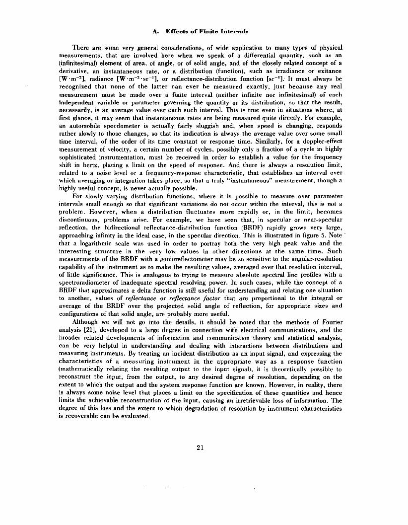
There are some very general considerations, of wide application to many types of physical measurements, that are involved here when we speak of a differential quantity, such as an (infinitesimal) element of area, of angle, or of solid angle, and of the closely related concept of a derivative, an instantaneous rate, or a distribution (function), such as irradiance or exitance W-m-*], radiance [W *sr-*], or reflectance-distribution function [sr-l]. It must always be recognized that none of the latter can ever be measured exactly, just because any real measurement must be made over a finite interval (neither infinite nor infinitesimal) of each independent variable or parameter governing the quantity or its distribution, so that the result, necessarily, is an average value over each such interval. This is true even in situations where, at first glance, it may seem that instantaneous rates are being measured quite directly. For example, an automobile speedometer is actually fairly sluggish and, when speed is changing, responds rather slowly to those changes, so that its indication is always the average value over some small time interval, of the order of its time constant or response time. Similarly, for a doppler-effect measurement of velocity, a certain number of cycles, possibly only a fraction of a cycle in highly sophisticated instrumentation, must be received in order to establish a value for the frequency shift in hertz, placing a limit on the speed of response. And there is always a resolution limit, related to a noise level or a frequency-response characteristic, that establishes an interval over which averaging or integration takes place, so that a truly “instantaneous” measurement, though a highly useful concept, is never actually possible.
For slowly varying distribution functions, where it is possible to measure over parameter intervals small enough so that significant variations do not occur within the interval, this is not a problem. However, when a distribution fluctuates more rapidly or, in the limit, becomes discontinuous, problems arise. For example, we have seen that, in specular or near-specular reflection, the bidirectional reflectance-distribution function (BRDF) rapidly grows very large, approaching infinity in the ideal case, in the specular direction. This is illustrated in figure 5. Note . that a logarithmic scale was used in order to portray both the very high peak value and the interesting structure in the very low values in other directions at the same time. Such measurements of the BRDF with a gonioreflectometer may be so sensitive to the angular-resolution capability of the instrument as to make the resulting values, averaged over that resolution interval, of little significance. This is analogous to trying to measure absolute spectral line profiles with a spectroradiometer of inadequate spectral resolving power. In such cases, while the concept of a BRDF that approximates a delta function is still useful for understanding and relating one situation to another, values of reflectance or reflectance factor that are proportional to the integral or average of the BRDF over the projected solid angle of reflection, for appropriate sizes and configurations of that solid angle, are probably more useful.
Although we will not go into the details, it should be noted that the methods of Fourier analysis 1211, developed to a large degree in connection with electrical communications, and the broader related developments of information and communication theory and statistical analysis, can be very helpful in understanding and dealing with interactions between distributions and measuring instruments. By treating an incident distribution as an input signal, and expressing the characteristics of a measuring instrument in the appropriate way as a response function (mathematically relating the resulting output to the input signal), it is theoretically possible to reconstruct the input, from the output, to any desired degree of resolution, depending on the extent to which the output and the system response function are known. However, in reality, there is always some noise level that places a limit on the specification of these quantities and hence limits the achievable reconstruction of the input, causing an irretrievable loss of information. The degree of this loss and the extent to which degradation of resolution by instrument characteristics is recoverable can be evaluated.
21

t*,o-. I O " 10. I O
- * 30.- 4-$ - 7 150' I
60'
10-1 10'. ' f r -10" IO"
60'
10-1 lo-' f r . l 0 A 10-1
FIGURE 5. Threedimensional graph of bidirectional reflectancedistribution function ( B R D F ) f , (33.2". 0"; 6 , . 4 ) (from [lo]).
22
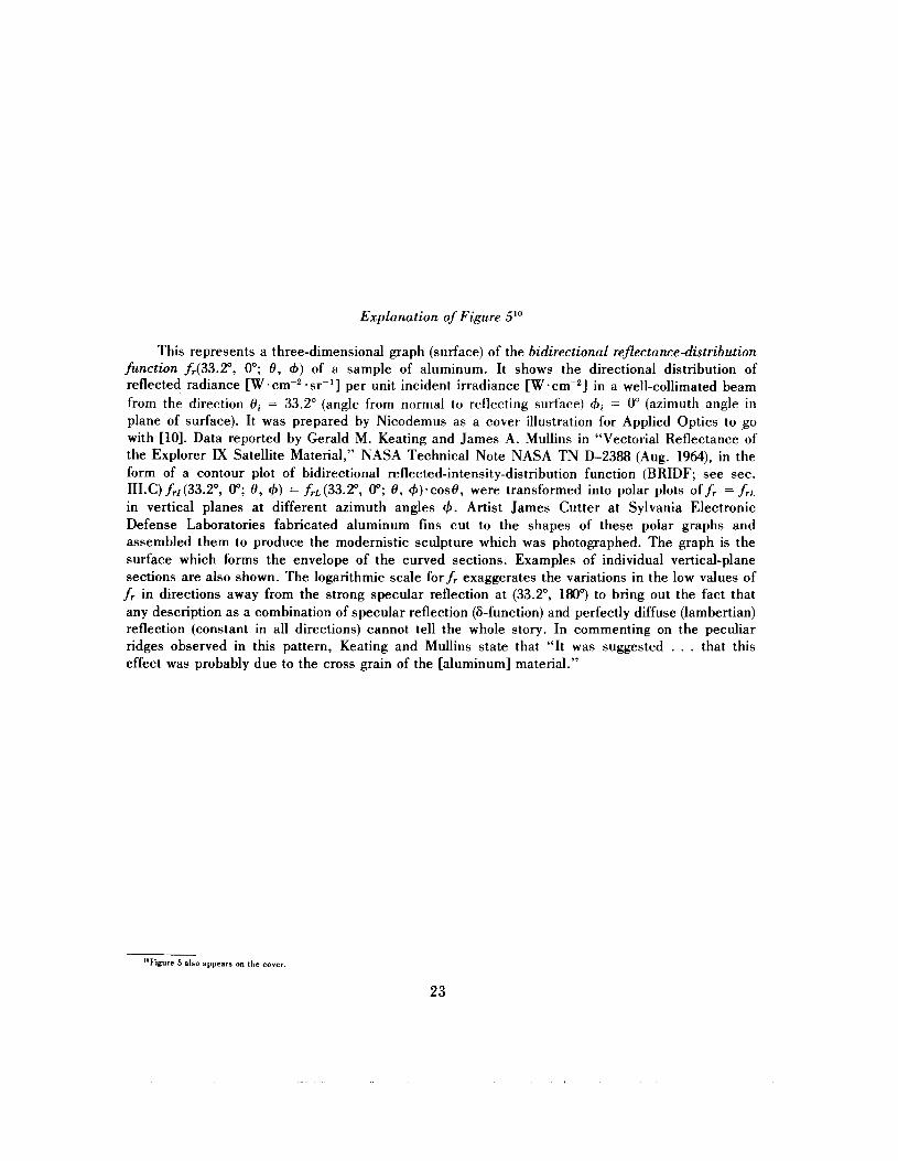
Explanation of Figure So
This represents a three-dimensional graph (surface) of the bidirectional reflectancedistribution function fr(33.2", 0"; 8 , 4) of a sample of aluminum. It shows the directional distribution of reflected radiance [W .cm-2 .ST-*] per unit incident irradiance [W . ~ m - ~ ] in a well-collimated beam from the direction Oi = 33.2" (angle from normal to reflecting surface) = 0" (azimuth angle in plane of surface). It was prepared by Nicodemus as a cover illustration for Applied Optics to ,go with [lo]. Data reported by Gerald M. Keating and James A. Mullins in "Vectorial Reflectance of the Explorer IX Satellite Material," NASA Technical Note NASA TN D-2388 (Aug. 1964), in the form of a contour plot of bidirectional reflected-intensity-distribution function (BRIDF; see sec. 1II.C) frl(33.Z0, 0"; 8, 4) = frL(33.2", 0"; 8 , +).cos8, were transformed into polar plots offr = f r L
in vertical planes at different azimuth angles 6. Artist James Cutter at Sylvania Electronic Defense Laboratories fabricated aluminum fins cut to the shapes of these polar graphs and assembled them to produce the modernistic sculpture which was photographed. The graph is the surface which forms the envelope of the curved sections. Examples of individual vertical-plane sections are also shown. The logarithmic scale forfr exaggerates the variations in the low values of
f r in directions away from the strong specular reflection at (33.2", 180") to bring out the fact that any description as a combination of specular reflection (&function) and perfectly diffuse (lambertian) reflection (constant in all directions) cannot tell the whole story. In commenting on the peculiar ridges observed in this pattern, Keating and Mullins state that "It was suggested . . . that this effect was probably due to the cross grain of the [aluminum] material."
"Figure 5 also appears on the cover
23
In addition to the problems of achievable resolution in measuring rates or derivative quantities, there is also the problem (still geometrical) of interaction between position and direction parameters, known as vignetting. Ostensibly, we should be able to extend the relations stated for a surface element to a larger portion of a plane reflecting surface merely by arranging for uniform isotropic irradiation and for reflection (collection or viewing) through the same solid angles or directions, respectively, for all elements of the more extended surface. However, with practical laboratory-size instrumentation, sources and receivers are not at infinity, although they can be optically at infinity if they are each positioned in the focal surface of a collimating or collecting optical system. But this, in turn, introduces still other problems.
The imperfect reflectance and/or transmittance of the optical elements of a collimator, and its aberrations, which may produce significant departures from perfect collimation or focusing, are not easy to control or to evaluate for their effects on a reflectance measurement. Similar considerations apply to the receiver and its associated collecting optics, if any. Even with ideally perfect optics, directional variations in the collimated beam will be produced by any variations in radiance across the surface of a source located in the focal plane; and the size of the solid angle filled by the collimated beam will depend on the size of the source (the solid angle that it subtends at the primary optics). Similarly, uniformity of radiance across the collimated beam (across the exit pupil or aperture of the collimator) depends on the radiation being isotropic (lambertian) at each point of the source. Since extended sources of uniform radiance that are isotropic over large solid angles are difficult to obtain, the problems involved in using a collimator become even greater for the larger solid angles of irradiance when “fast” optics (of low, f number) are used. Similar considerations apply to the receiver and its associated collecting optics for the larger solid angles of collection (of reflected radiation).
It is particularly hard to achieve uniform, isotropic irradiation and/or collection of reflected flux from a full hemisphere above an extended flat reflecting surface, even without considering the unavoidable problem of spatial overlapping of the two beams when one (or both) of them fills the full hemisphere. The integrating sphere probably offers the most satisfactory approach from the standpoint of geometry alone, but it introduces problems of achieving adequate power levels for detection and even more serious difficulties due to spectral variations in the reflectance of available wall materials. Again, we do not go into details but merely call attention to the possible difficulties in extending the nomenclature and concepts to real situations involving extended reflecting surfaces.
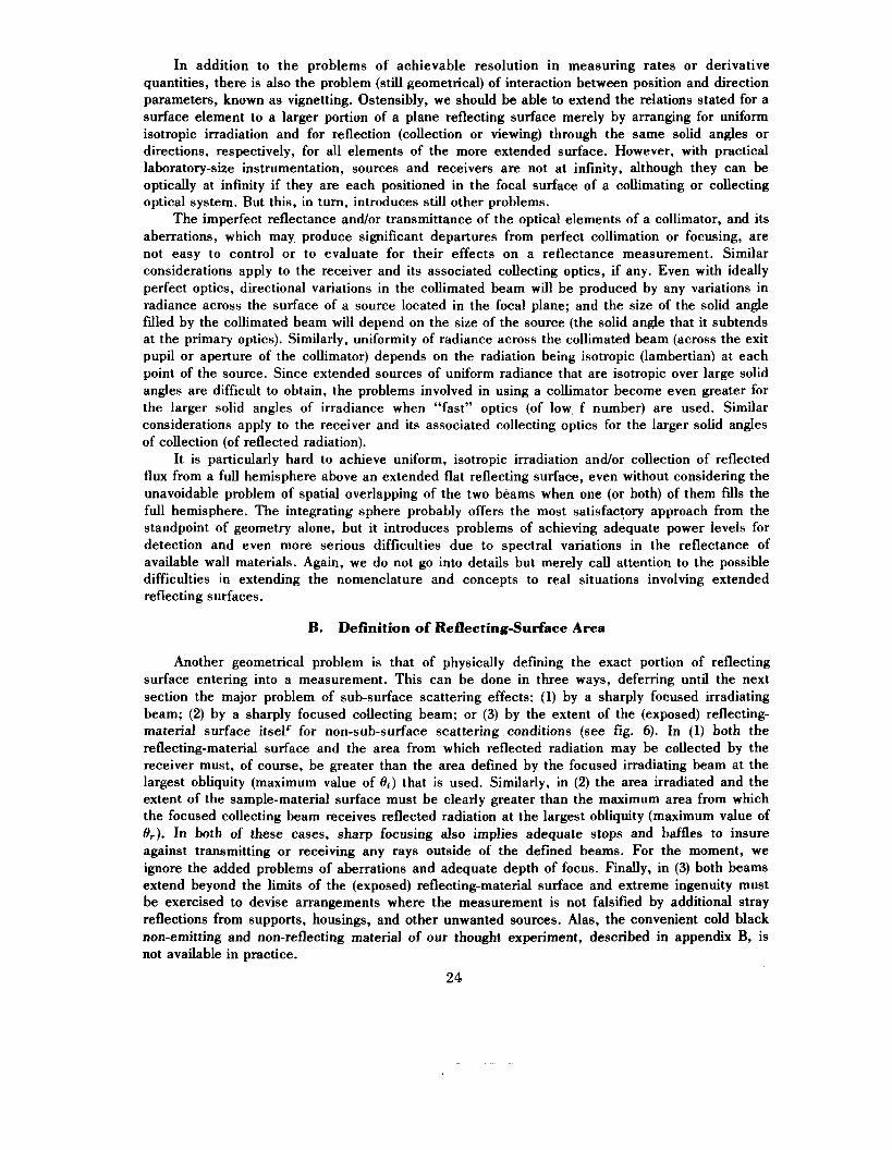
B. Definition of Reflecting-Surface Area
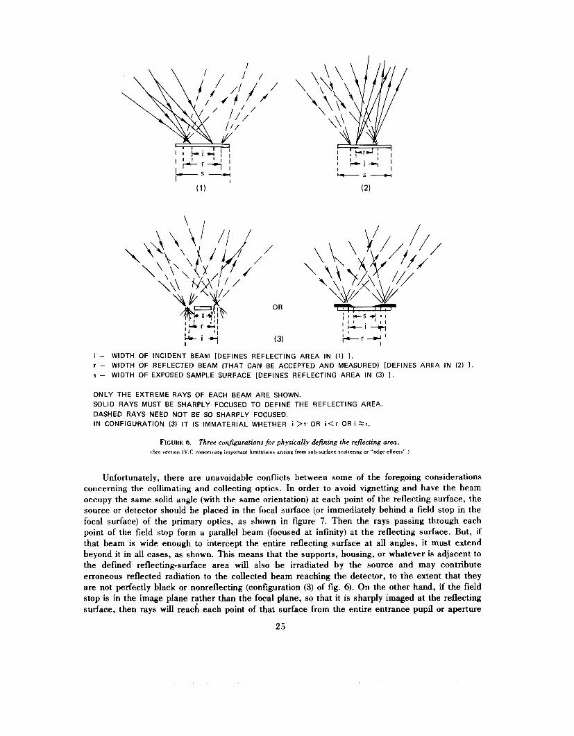
Another geometrical problem is that of physically defining the exact portion of reflecting surface entering into a measurement. This can be done in three ways, deferring until the next section the major problem of sub-surface scattering effects: (1) by a sharply focused irradiating beam; (2) by a sharply focused collecting beam; or (3) by the extent of the (exposed) reflecting- material surface itsel‘ for non-sub-surface scattering conditions (see fig. 6). In (1) both the reflecting-material surface and the area from which reflected radiation may be collected by the receiver must, of course, be greater than the area defined by the focused irradiating beam at the largest obliquity (maximum value of 0,) that is used. Similarly, in (2) the area irradiated and the extent of the sample-material surface must be clearly greater than the maximum area from which the focused collecting beam receives reflected radiation at the largest obliquity (maximum value of Or). In both of these cases, sharp focusing also implies adequate stops and baffles to insure against transmitting or receiving any rays outside of the defined beams. For the moment, we ignore the added problems of aberrations and adequate depth of focus. Finally, in (3) both beams extend beyond the limits of the (exposed) reflecting-material surface and extreme ingenuity must be exercised to devise arrangements where the measurement is not falsified by additional stray reflections from supports, housings, and other unwanted sources. Alas, the convenient cold black non-emitting and non-reflecting material of our thought experiment, described in appendix B, is not available in practice.
24
“‘LL’
i - WIDTH OF INCIDENT BEAM [DEFINES REFLECTING AREA IN (1) 1 . r - WIDTH OF REFLECTED BEAM (THAT CAN BE ACCEPTED AND MEASURED) [DEFINES AREA IN ( 2 ) I s - WIDTH OF EXPOSED SAMPLE SURFACE [DEFINES REFLECTING AREA IN (3) I .
ONLY THE EXTREME RAYS OF EACH BEAM ARE SHOWN. SOLID RAYS MUST BE SHARPLY FOCUSED TO DEFINE THE REFLECTING AREA. DASHED RAYS NEED NOT BE SO SHARPLY FOCUSED. IN CONFIGURATION (3) IT IS IMMATERIAL WHETHER i > r OR i < r OR i Z r ,
FIGURE 6. Three confwurations for physically defining the reflecting area. (See section 1V.C concerning important limitations arising fmm subsurface scattering or “edge effects”.)
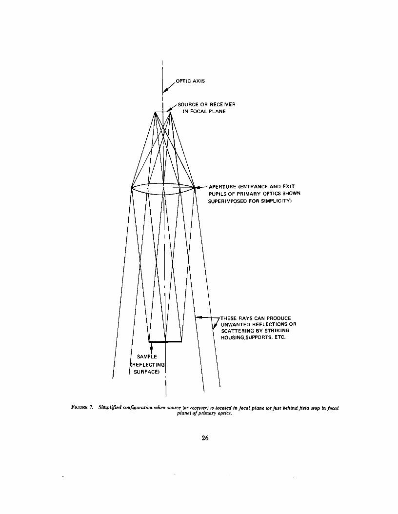
Unfortunately, there are unavoidable conflicts between some of the foregoing considerations concerning the collimating and collecting optics. In order to avoid vignetting and have the beam occupy the same solid angle (with the same orientation) at each point of the reflecting surface, the source or detector should be placed in the focal surface (or immediately behind a field stop in the focal surface) of the primary optics, as shown in figure 7. Then the rays passing through each point of the field stop form a parallel beam (focused at infinity) at the reflecting surface. But, if that beam is wide enough to intercept the entire reflecting surface at all angles, it must extend beyond it in all cases, as shown. This means that the supports, housing, or whatever is adjacent to the defined reflecting-surface area will also be irradiated by the source and may contribute erroneous reflected radiation to the collected beam reaching the detector, to the extent that they are not perfectly black or nonreflecting (configuration (3) of fig. 6). On the other hand, if the field stop is in the image plane rather than the focal plane, so that it is sharply imaged at the reflecting surface, then rays will reach each point of that surface from the entire entrance pupil or aperture
25
/OPTIC
SOURCE OR RECEIVER I N FOCAL PLANE
APERTURE (ENTRANCE AND EXIT PUPILS OF PRIMARY OPTICS SHOWN SUPERIMPOSED FOR SIMPLICITY)
THESE RAYS CAN PRODUCE UNWANTED REFLECTIONS OR SCATTERING BY STRIKING HOUSING,SUPPORTS, ETC.
FIGURE 7. Simplified conhuratwn when source (or receiver) is located in focal plane (or just behind field stop in focal plane) of primary optics.
26
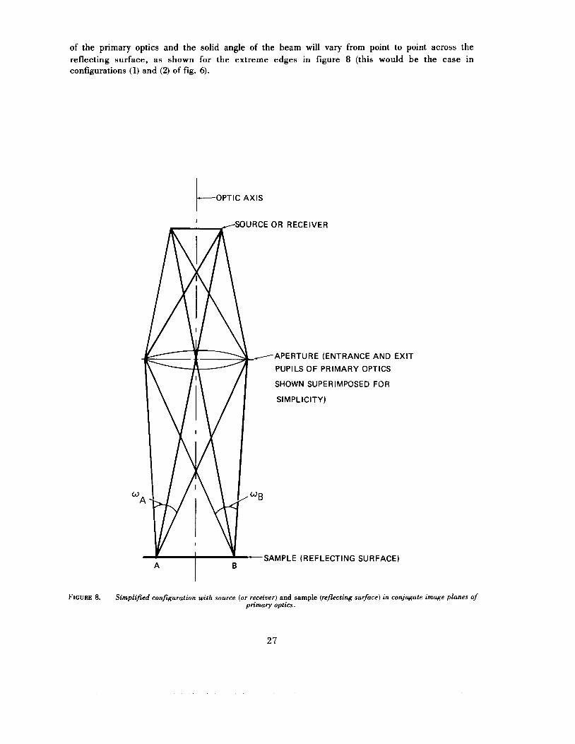
of the primary optics and the solid angle of the beam will vary from point to point across the reflecting surface, as shown for the extreme edges in figure 8 (this would be the case in configurations (1) and (2) of fig. 6).
OPTIC AXIS t
APERTURE (ENTRANCE AND EXIT
PUPILS OF PRIMARY OPTICS
SHOWN SUPERIMPOSED FOR
SIMPLICITY)
'ING SURFACE)
FIGURE 8. Simplified configuration with source (or receiver) and sample (reflecting surface) in conjugate image planes of primary optics.
27
C. Sub-Surface Scattering (Edge Effects)
Earlier (sec. II.A), we treated sub-surface scattering in terms of the BSSRDF (eqs (1) and (2)) without making any assumptions about the mechanism(s) involved. However, it may be helpful to look briefly at a few considerations, without examining possible mechanisms in any great detail. For example, for very rough surfaces we may choose a reference plane lying just above the highest points. Then microscopic analysis would reveal many interreflections between the surface irregularities by which an incident ray would be returned as reflected radiation through a point of the reference plane different from the point through which the incident ray entered the space beneath. An example might be a roughened metal surface, or again, the surface of the moon, with large hills and valleys, viewed from the great distance of the earth. Probably the most common situation, however, is the body scattering within the material of most diffuse reflectors.
For body scattering materials, besides the Fresnel reflection, there are diffuse reflections produced by internal scattering [22-251, usually multiple scattering, in the material below the nominal reflecting surface (usually the boundary between that material and the air above it). This occurs with diffuse reflectors, which include, in varying degrees, nearly all natural reflecting- surface materials, depending to a great extent on their opacity, i.e., on the degree to which the incident beam penetrates into the material before being absorbed or scattered back through the surface again, each ray emerging at a point which, in most cases, is different from the point of incidence (for that ray). The reflected rays each include radiation which is incident at adjacent points as well, and for the more translucent materials, the separation between the points involved in such interaction can be quite substantial [26]. In such cases, it is necessary to either irradiate a large area and view a smaller area (or vice versa), as indicated in section 1I.A.
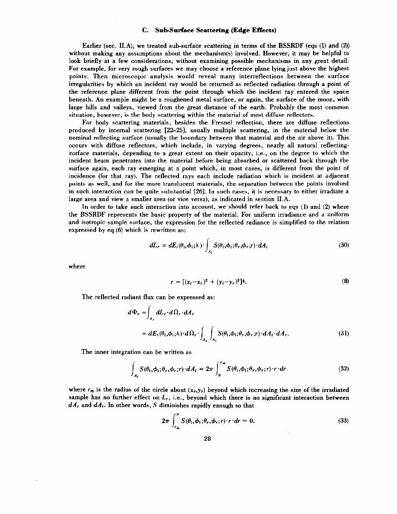
In order to take such interaction into account, we should refer back to eqs (1) and (2) where the BSSRDF represents the basic property of the material. For uniform irradiance and a uniform and isotropic sample surface, the expression for the reflected radiance is simplified to the relation expressed by eq (6) which is rewritten as:
where
The reflected radiant flux can be expressed as:
The inner integration can be written as
where r,,, is the radius sample has no further dAr and dAg. In other
of the circle about (xr,yr) beyond which increasing the size of the irradiated effect on L,, i.e., beyond which there is no significant interaction between
words, S diminishes rapidly enough so that
This means that, when the two areas Ai and A, are unequal, with one completely contained within the other and with a band of width greater than r, between their margins all around, the integral over the larger area is effectively limited to just the area covered by the smaller plus a band of width r , surrounding it. If we denote the area of such a band, of width r,, surrounding the smaller area as u(rm), then, if [Ai+u(r,)] lies wholly within A,, the double integral of eq (31) becomes
but if we reverse the directions of all rays so that incident and reflected beams are exactly interchanged, then A,+u (r,) lies wholly within Ai and the double integral becomes, instead,
S (ei ,+i ; 8, ,+, ;r) dAi dA , [ mZ sr-']. Jlr i , ,a ,rm, (35)
Since, in this case S (Oi,+i;Or,c#+;r) involves the coordinates (xi,yJ and (xr,y,) only symmetrically through r, it follows that the integrals (34) and (35) are equal. Hence, it is immaterial which of the areas is the smaller, the irradiated area Ai or the defined area A, from which reflected radiation is collected and measured. For a given magnitude of that smaller area, as long as it is contained in the larger area and separated from the boundary of the larger area by a band of width equal to or greater than rm in all directions, the reflected radiant power collected and measured will be the same. Furthermore, if Ai and A, are concentric circular areas that can be adjusted in size, rm can be estimated or measured (with respect to the noise level or resolution limit of the reflectometer) by starting with them nearly the same size and gradually increasing the larger one until there is no longer any observable increase in the signal from the radiation detector. At this point the radial separation between their boundaries is equal to r,.
It is assumed throughout the foregoing discussion that the sample size A, >> Ai or A, and that the distance from the boundary of the larger area Ai or A, to the sample edges is much greater than r, . Otherwise, there may be disturbing internal reflections and/or scattering from the margins of the sample. It should also be reiterated that this analysis applies only to samples that have uniform isotropic scattering properties parallel to the nominal reflecting surface, and it should be noted that it is essential that the uniformly-irradiated sample area extend in all directions beyond the edges of the observed reflecting area, or vice versa, by more than the distance r,, i.e., that r > rm for each pair of incident and exitent points lying, respectively, on the margins of Ai and A,.
It should be emphasized that this quantity rm is not a fixed distance for a given material; it is a function also of the desired degree of accuracy or approximation accepted in eq (33). An example, which provides a method for directly estimating r,, is to visually (with suitable precautions for eye protection) observe the reflection from a point intensely irradiated by a sharply focused beam, such as that from a laser source. The radius of the visible band of diminishing radiance or brightness surrounding the intense central spot is r,, to the degree of approximation established by the strength of the source and the threshold of visibility for the particular circumstances. For larger (>2r , across in any direction), sharply focused, uniformly illuminated areas, the width of the bund of gradually diminishing brightness surrounding the central region of uniform brightness will be approximately 2r,. Note also that r, is usually spectrally dependent, having different values for different wavelengths.
From the equality of integrals (34) and (35) it follows that the measurement configurations (1) and (2) of figure 6 are equivalent. In the case of configuration (l), the choice of r , may be described as being large enough to collect all of the reflected light due to the irradiation of Ai, while in the case of configuration (2), the choice of r, may be described, as before, as being large enough to include all of the irradiated area which contributes significantly to the radiance from A,.
29

Of the two, configuration (1) of figure 6 is the one that is more likely to be used in a reflectometer that measures reflectance, rather than a reflectance factor, by measuring, separately, the radiant flux in both the incident and reflected beams. On the other hand, configuration (3) of figure 6 should not be used for materials for which sub-surface scattering is appreciable, but rather should be restricted to cases in which surface (Fresnel) reflectance of highly opaque material, such as metal, is to be measured. In this configuration, as well as in configurations (1) and (2) for which rm is not chosen large enough, scattered radiation passes laterally beyond the edges of the defined area with no opportunity for any of it to be returned into the reflected beam, or there is not enough (if any) compensating scattered radiation coming back through those edges from irradiated surface elements outside the defined area. These “edge losses” may account for otherwise unexplained differences in reported values of reflectance or reflectance factor for a given sample measured with different instruments, since the exact configurations employed in the different instruments vary considerably.
For materials that are uniform, but are non-isotropic, the illustrative situation of an intensely illuminated point would no longer produce a circular region of gradually diminishing brightness. Instead, it would be elliptical or perhaps even more irregular and 2rm would correspond to its greatest width (diameter) in any direction. Furthermore, the requirement for uniformity, that S be independent of the location of the temporarily fixed point, can also be relaxed to a requirement for only statistical macroscopic uniformity, with variations only over small enough distances so that they are not significant.
D. Extrapolation to Different Geometries
It is easily shown that, for any beam geometry, the reflectance is given by
p (wi;wr) = x(wi ;wr ) - f l r [dimensionless],
where
is the averaged BRDF, with respect to projected solid angle, over both the solid angle of incidence and the solid angle of reflection (collection). In fact, this is readily apparent upon comparing eqs (36) and (37) with eq (16). Thus, as the beam geometry changes, as long as the average value of the BRDFf, is not significantly changed, it is only necessary to multiply it by the new value of a,, if any, to obtain the reflectance p for the new beam geometry. If no measurements are available that were taken with the beam geometry-for which a reflectance value is required, the best estimate is obtained by using the value of fr (based on a measured value of reflectance factor) for the beam geometry that most nearly approximates the desired one, and multiplying it by the appropriate value of a,. If possible, also try to take into account any supplemental data that might indicate how the value offr may vary with the directions involved in the differences between the two geometries. Some practical problems and some measurement results are reported by Hsia and Richmond 1271. Part I1 of their paper [27] is a useful bibliography on diffuse reflectance.
E. Other Radiation Parameters and Fluorescence (or Phosphorescence)
Reflectance, like absorptance and transmittance, may be highly dependent on the wavelength or frequency v [THz] (as distinguished from modulation or fluctuation frequency f << v) of the radiation. Accordingly, selective reflection may frequently alter the spectral distribution in a beam of radiation, so that the spectral-total reflectance (all wavelengths), even of identical surfaces, may change as a beam, which includes an extended distribution of wavelengths, undergoes successive
30
reflections. If there is interaction between spectral and geometrical parameters, as just noted as a possibility in materials with significant internal scattering, the geometrical distribution may also be affected. In so-called linear situations, where propagation effects, ,such as reflection, are independent of the strength of the beam, mathematical treatment is simplified by dealing with relative factors and distributions, usually normalized to a maximum of one. We will not consider non-linear situations where radiation effects are intensity-dependent except to remind the reader that, with high-powered lasers becoming available, such non-linear optical effects are being encountered more frequently as time passes.
The bidirectional reflectance-distribution function to be used in evaluating all of the reflectances, reflectance factors, and MRDFs can be expressed by the weighted average of the BRDF with respect to wavelength, with the spectral distribution of the incident radiation beam as the weighting function. If, however, there is no interaction between the wavelength or frequency dependence and the geometrical dependence of reflection, the functions are separable. Then
wherefr(A) is normalized to have a maximum value of one by choosing
where A , is the wavelength at which the value of the right side of eq (39) is a peak or maximum; hence fr(A,) = 1. Then it is only necessary to multiply any reflectance, reflectance factor, or MRDF, computed from the BRDF given by eq (39) by the weighted average of fr(A), with the spectral distribution (relative is sufficient) of the incident beam as the weighting function XA(A), i.e., by
f r [z~ (h) ] = J z~ (A) I f , (h ) .dh l j x,(A)*dA [dimensionless], 0 0
where XA(A) = XA(A)/C is the relative spectral distribution of the incident beam; XA(A) is the spectral radiometric quantity characterizing the beam; X may be any one of the radiometric quantities Q, a, I , E , M, or L; C is a constant with respect to wavelength.
Unfortunately, we are not aware of any data that will establish the extent to which there may be interaction between geometrical dependence and spectral dependence, except for the knowledge that it is a significant factor in some internal-scattering situations, as pointed out earlier, in addition to the obvious case of a diffraction grating where there is clearly substantial interaction. Certainly, there will be some wavelength bands over which the interaction is so slight that this last procedure will yield a good approximation, and it will probably hold more widely. But until more complete bidirectional reflectance-distribution data are gathered to establish such dependencies, we can only speculate and caution against the possibility of interaction effects.
Of the radiation parameters [5,28], the modulation or fluctuation frequency f (< < v ) appears to be unique in that, up to the limit of the frequency-response capability of available radiation detectors, there ordinarily appears to be no frequency-f dependence on the part of the propagation properties of matter-radiation interaction, the transmittance and the reflectance (or scatterance). This means that coding of an incident beam by time-modulation or chopping can be used, and is widely used, to distinguish between its effects and those due to other ambient radiation that is difficult to control and/or measure accurately and comprehensively. For example, in many reflectometers, the incident beam is chopped, and synchronous amplifiers are used to insure that the receiver-amplifier is responding only to reflected radiation produced by that incident beam and not to reflected radiation from other ambient incident rays and/or emitted thermal radiation from the sample surface and from other ambient objects, including the collecting optics, if any, of the receiver.
31

Finally, the last of the radiation parameters, polarization, is often neglected or ignored, and we know of no published treatment that adequately deals with its implications for radiometry, although it can strongly affect the propagance, particularly the reflectance, in many situations. Chapter 6 on polarization has been prepared for the “Self-study Manual on Optical Radiation Measurements” [28] and has been published in June 1977 as NBS Technical Note 910-3, and we hope that it will help to clear up some of the problems in this area. Meanwhile, we note that a full description of the polarization of a beam can be given in terms of the four Stokes parameters [B], each of which can be regarded as representing a component of that beam. Then, with four such components for the incident beam, each possibly contributing to four such components in the reflected beam, the most general description of the possible interactions would require a matrix of sixteen (four x four) BRDFs. This matrix approach, but with fewer components (not the most general case), is used in [30].
This topic will not be developed further here except to re-emphasize the fact that polarization can have a very large effect on reflectance, particularly in the case of specular reflectance. This may not be particularly significant when measuring a single reflection of unpolarized incident radiation with an unpolarized detector (one insensitive to polarization). Too often, however, it is assumed that an incident beam is unpolarized when, in fact, it is not, and/or that a detector is unpolarized when it is not. Actually, any off-normal emission [31], or off-normal reflection or refraction of an unpolarized incident beam, will produce some polarization. The latter, however, is often obscured because the cylindrical symmetry of refraction by circular lenses produces no net polarization. Similarly, there is usually no net polarization from circular focusing mirrors used on- axis, as in a Cassegrain configuration, but off-axis or asymetrical systems, such as a Newtonian configuration or an off-axis paraboloid, may exhibit substantial polarization characteristics.
Fluorescence (or phosphorescence), if present, greatly complicates the measurement of reflectance. The phenomenon of fluorescence involves the absorption of photons within one frequency (photon-energy) range to produce emission of photons within a second, lower frequency (photon-energy) range after a time interval governed by an exponential decay, characteristic of the half-life of the excited atoms. If such re-emission persists noticeably (sometimes even for hours) it is called phosphorescence.” Reflection, on the other hand, is the process by which radiant flux incident on a surface or medium leaves that surface or medium on the incident side without change in frequency (spectral frequency v = c/Ao). Thus, the flux produced by fluorescence (or phosphorescence) is, by definition, not reflected flux. But both will be present in any real measurements of fluorescent (or phosphorescent) materials so that spectral dispersion of both incident and observed radiation is required to distinguish between them. If the incident beam is restricted to a narrow spectral range by a monochromator, radiation of that same spectral frequency, observed to be leaving the surface only when it is irradiated, is reflected radiation. Similar observations of a lower exitent spectral frequency establish the presence of fluorescent (or phosphorescent) emission. Further, if the incident beam is modulated, the fluorescent (or phosphorescent) emission will be found to be modulation-frequency dependent because of the time constant associated with the exponential decay characteristic of the excited atoms. The details of such measurements are a separate problem that will not be discussed further here.
F. Use of Reference Standards
The absolute value of reflectance is usually very difficult to measure. The main problems are to measure the solid angle of viewing and to measure the flux in .the incident beam accurately. This usually requires removal of the sample of reflecting surface as well as shifting of the detector (collector) and it is hard to be sure that the geometry (throughput) of the measured beam is exactly the same as that of the beam incident on the sample (when it is replaced) that produces the
“Fluorescence is characterized by a time delay of less than about 10 [ns]. Re-emission after 10 [ns], sometimes much later than 10 [ns], is called phosphorescence.
32

reflected beam. For precise and accurate measurements, the flux in the incident beam and its distribution in position and direction, as it impinges on the sample surface, must be completely known. (We ignore the equally important spectral and polarization parameters for this discussion.) However, once the absolute reflectances of a set of reference standards are carefully measured, the reflectance measurement of an unknown sample can be more easily done by the comparison method. The BRDF of the chosen reference standard should resemble that of the sample as closely as possible to minimize the sensitivity to instrument-alignment errors.
On the other hand, the measurement of a reflectance factor being inherently a comparison measurement, the beam-defining apertures for both source and detector (receiver) beams can be left undisturbed while a sample and a comparison-standard surface are interchanged. Accordingly, with identical beam geometry thus insured, it is much easier to achieve high precision (repeatability) in the measurement of reflectance factors. The main limitation on measurement accuracy is then the fact that there is no ideal (1Wo) perfectly diffusing (lambertian) comparison-standard surface. When the departure of the actual standard from 100 percent reflectance, and from a perfectly isotropic (lambertian) diffusing characteristic, are accurately known, appropriate allowance can be made for them. For the highest accuracy, however, this also involves the exact beam configuration and throughput for both the incident and reflected beams and the BRDF of the comparison- standard surface (in order to know exactly how much it differs from the ided perfectly diffusing standard in the particular measurement configuration). Finally, a knowledge of at least the relative BRDF of the unknown surface being measured is also needed for any estimate of the accuracy and signficance of the final measurement result. Only with this information can the sensitivity of the measurement result to small changes in beam geometry be assessed. The final result, of course, is valid only for the particular beam geometry of the measurement. The BRDF information is needed to determine how restrictive that limitation may be in the particular case.
Incidentally, it turns out that one of the comparison standards which can be most accurately characterized in terms of its BRDF for such use in the measurement of reflectance factors is a specular reflector. For convenience, to keep the total incident flux on the detector (receiver) more nearly at the same level for all of the measurements, one of low reflectance, such as a polished flat black glass of known specular reflectance ps,, is used. Its BRDF is then closely approximated by eq (ClO).
V. Summary, Conclusions, and Recommendations
Within the domain of geometrical (ray) optics, the description and specification of the geometrical reflecting properties of any surface are given by the bidirectional scattering-surface reflectance-distribution function (BSSRDF) S. In most cases, however (see sec. 1I.A for the necessary conditions), they can be adequately specified by the simpler bidirectional reflectance- distribution function (BRDF) f r . Other useful geometrical reflectance quantities, including reflec- tances and reflectance factors, are expressed and interrelated in terms of the BRDF. The effects of radiation parameters, other than geometrical, including polarization, and of fluorescence, are briefly discussed and their importance in the measurement and specification of reflectance quantities is indicated.
Within the limited scope we impose on ourselves for this monograph, our principal recommendations for the approach to the geometrical description and specification of reflecting properties of surfaces, and for nomenclature to facilitate that approach, are:
1. The term “bidirectional reflectance-distribution function’’ (BRDF) and symbol fr(Oi,&;Or,&) should be adopted and this quantity, under appropriate conditions (see sec. II.A), should be recognized as the basic quantity to be used in defining all other reflectance quantities or measures of reflectance, except in some situations involving substantial subsurface scattering.
2. The beam geometry should always be completely specified (including uncertainties) in any quantitative statement aboht reflectance.
33
3. The nomenclature of tables 1 and 2, including McCamy’s notation for right-circular-conical beams, should be adopted.
4. Other schemes of concepts and nomenclature to cover special beam geometrics should be considered acceptable as long as they are clearly defined in terms of bidirectional reflectance- distribution function (BDRF) or the bidirectional scattering-surface reflectance-distribution function (BSSRDF) (including adequate consideration of any special conditions).
With the foregoing as a point of departure, we hope that, in time, our approach can be extended to also take into account the effects of the other radiation parameters, particularly polarization.
While we strongly urge the appropriate organizations concerned with establishing nomenclature standards to consider the foregoing recommendations, we should, at the same time, clarify our position with respect to all such standards. Standardization is an important requirement for efficient communication. Standards should be adopted as rapidly as a workable consensus in support of them can be established. On the other hand, they should never be permitted to become a strait jacket that stifles innovation and progress. An author who feels that he needs new and different nomenclature to adequately express his ideas should always be free to adopt and use such nomenclature. However, he should always do so explicitly, defining his nomenclature or usage clearly and, as far as possible, showing how it is related to, or differs from, any pertinent standard nomenclature. In fact, we fully expect that we, ourselves, may not infrequently find occasion to depart from the detailed nomenclature proposed in this monograph. But we also accept the obligation, when doing so, to define any such nomenclature and to relate it, where appropriate, to existing standards and/or to our recommended standards.
In conclusion, we want to emphasize that this monograph is not primarily intended to propose or advocate any particular nomenclature. Far more important than the nomenclature are the underlying concepts which we believe are essential to full understanding and effective treatment of reflectances and related quantities. We introduce nomenclature only in order to be able to talk about the concepts. The essential point is the recognition that complete specification of the reflecting properties of a highly opaque material’* must take into account the directional distribution (in terms of radiance) of radiation in both the incident and reflected beams. Finally, when there is significant internal scattering, which is true in some degree for all diffusely reflecting materials, it must also be recognized that rays incident at one point contribute to the exitent “reflected” radiation from adjacent points. We have shown how these considerations can be treated and have proposed nomenclature to facilitate that treatment.
VI. Appendix A. Background and Basis for Recommendations
In this appendix we present, briefly, the basis for our recommendations, particularly where they represent changes from earlier proposals and practices.
Reflectance nomenclature, primarily from the standpoint of beam geometry, including concepts, terms, and symbols, was discussed by Nicodemus [lo] in an analysis of the interrelation- ship between directional reflectance and directional emissivity or emittance (Kirchhoff s law), and by Judd C121 from the standpoint of reflectometry. Subsequent experience revealed inadequacies in and inconsistencies between the two approaches, as well as useful interrelationships. Within a year following the publication of Judd’s paper [12], four of the authors of this monograph (Nicodemus, Richmond, Ginsberg and Limperis) had met and outlined most of what is presented here. We have tried to eliminate the inadequacies and inconsistencies of the two earlier papers, recommending nomenclature that incorporates the best from both of them. This is supplemented by the multivariate approach (see table 3), devised by two of us (Ginsberg and Limperis) and by
” Material in which there is negligible separation (for a particular application) between the point of incidence of a ray and the points of exitence of all resulting internally scattered rays leaving the “reflecting” surface.
34

the approach of McCamy [13] who was concerned with transmittance and reflectance in connection with photographic imagery. Preparation of this paper for publication was repeatedly delayed for a variety of reasons. Meanwhile, Nicodemus became aware that a number of his earlier recommendations for terminology and symbols, that we had agreed were undesirable and in need of revision, were being rather extensively used. Accordingly, he published a letter to the editor of Applied Optics [9] to set the record straight on those points.
The changes from Nicodemus’ earlier nomenclature [lo] included in our recommendations are summarized in table 4, from [9]. The reasons for them are also essentially those *given in [9].
TABLE 4. Comparison between recommended reflectance nomenclature and that of [IO]*
Recommended Ref-[ 101 symbol Item Quantity, Quantity, No. Recommended terminology Ref-[lo] terminology symbol
9
10
Radiant power . . . @ P Radiant intensity . . . I J Radiant exitance (radiant emittance) M W Irradiance . . . E H Radiance . . . L N Solid angle . . . w R Projected solid angle . . . (1 R‘ Bidirectional reflectance- (Partial reflectance, or f r P‘
distribution function bidirectional reflectance)
reflectance
reflectance factor
Directional-hemispherical (Directional reflectance) p(H, ,9, ; 2n) pdt (et, d’t )
Hemispherical-directional (Directional reflectance) R ( 2 T Or ,&) Pdr(’% 74,)
*from [9].
Items 1 through 5 merely establish conformity with the radiometric nomenclature of [4]. Items 6 and 7 follow a practice suggested by R. Clark Jones [32], leaving the prime notation available for other purposes. Solid angle and projected solid angle are explicitly defined and discussed in [2].
Item 8, the bidirectional reflectance-distribution function (BRDF) h, is the most important entry in table 4. Except for considerations of sub-surface scattering (see the last paragraph of this section), it is the basic quantity, underlying all of the reflectance nomenclature recommended in this paper. It has [2] unit-dimension [sr-’1 and its value may range from zero to extremely high values, even going to infinity in the delta-function form for ideally specular reflectance in eq (C10). It is, therefore, important to distinguish it clearly from reflectance, the dimensionless ratio 0 5
p 5 1 of eq (15a). However, both the terms “partial reflectance” and “bidirectional reflectance” (especially the latter) and the symbol p ’ , to denote the BRDF, have caused much confusion by failing to emphasize this distinction adequately. The poor choice of terms is probably most to blame, since the prime notation is widely used for derivatives elsewhere in other connections. However, in line with our desire to free the prime for other purposes and because the confusion with p has occurred, even though the terminology rather than the notation may have been primarily responsible, we are recommending the notation fr. Furthermore, both the new term and new symbol help to emphasize the nature of this quantity as a distribution function, encouraging appropriate utilization of existing mathematical treatments of distribution functions in general. Finally, the fact that two directions are involved is clearly denoted by the physically descriptive modifier “bidirectional” and by the explicit statement of functional dependence in the full notation
Items 9 and 10 clarify the nature of two quantities (both called reflectances in [lo]) by the application of Judd’s (modified) terminology and symbols, which show that while one is a reflectance, the other is actually a reflectance (radiance) factor. As shown in [lo], and recognized in [12], these two quantities for a given direction are always equal (Le., p ( 8 , 4 ; 2 r ) = R(%;O,+)) as a direct consequence of Kirchhoffs law (as orginally stated in directional form), regardless of Helmholtz reciprocity [9].
fr (4 7 4 ; 6, 94r ).
35
Judd’s [12] scheme of functional notation for designating the beam geometry for any reflectance quantity has been adopted with certain modifications. We prefer the semicolon used in an earlier draft of fudd’s paper [12], rather than the colon that appeared in the published paper, for separating the parameters designating the incident-beam geometry from those designating the geometry of the reflected (collected) beam. This avoids possible confusion with similar use of a colon in other notations. We also prefer the more explicit w rather than Judd’s g as the symbol for the conical beam geometry, and have extended it to include, also, the extremes of an element of solid angle do (which we use interchangeably with (e,+) to denote a well-collimated beam in a given direction) or a full hemisphere of % [sr]. The use of w is also more consistent with the other symbols; this way, all three-dw, w, and %-represent solid angles. The nine permutations of three incident and three reflected (collected) beam geometries (see fig. 3) used by Judd have been followed in tables 1 and 2, except that the order has been reversed. We start with the bidirectional quantity and end with the bihemispherical quantity. This seems more consistent with the approach of building up all of the quantities by integration and/or averaging of the BRDF, as shown in the last column of each table.
In table 1, note that three quantities-bidirectional reflectance dp(Oi,+i;&.,&), conical- directional reflectance d p (wf;O,,+,), and hemispherical-directional reflectance dp(2n;O,, &)-are all designated as differentials by the notation used, the reason being clear from the last expression on the same line, giving each quantity in terms of the BRDF. Judd [12] speaks of integrating the bidirectional reflectance to obtain other forms of reflectance but, unfortunately, used the notation p rather than the differential notation dp for all three of these quantities. All of Judd’s [12] rather involved sets of interrelationships between the various quantities in both tables 1 and 2 are readily apparent and derivable from the consistent set of expressions for each quantity in terms of the BRDFf,(Oi,$Ji;B,,+,) in the last column of each table.
In table 2, we propose a clear departure from the terms and symbols of Judd [12] and of ANSI [4] and its source, the CIE [14], by abandoning the term radiance factor and the symbol fi for the three quantities: bidirectional-reflectance factor R (Oi,+i;&.,&), conical-directional reflectance factor R (wi;O,,&), and hemispherical-directional reflectance factor R (27r;Or,&). In this way, the close interrelationship of all nine quantities in table 2, all of which are contained in the expression for the biconical reflectance factor R(wi;w,), if the range for the solid angles wi and o, is extended to include the extremes of an element of solid angle do and a full hemisphere of 2?r [sr], is more clearly apparent. On the other hand, since first deciding on this recommendation, we have realized that there are occasions when one may wish to make a general statement about a radiance factor fi which applies equally to any one of the three, or about the radiance factors fi generally, which applies to all three, but in neither case to any of the other reflectance factors. In the newly proposed nomenclature, it is very awkward to make such a distinction between these three quantities and the other reflectance factors. Accordingly, we also favor retention of the older nomenclature as an acceptable alternate form.
From the outset, we were aware, also, of the phenomenon of sub-surface scattering and so- called “edge effects” in diffuse reflectors, particularly in obviously translucent materials. Accordingly, the discussion of the “edge effects’’ (sec. 1V.C) was developed. However, since it justified wide continued use of the formalism already established on the basis of the BRDF, we left it there and made relatively little mention of it earlier. Later, during reviews at NBS, in order to improve clarity and continuity, Venable and Hsia proposed a new approach in which the more general BSSRDF was introduced first and the BRDF was then developed as the important special case. Meanwhile, their publication [8] established the even more general scattering function S , of which the BSSRDF is a special case. The main body of this monograph was, accordingly, rewritten using this approach.
36
VII. Appendix B. Details of Reflectance Derivations (A Thought Experiment)
Consider a large, opaque hemisphere with walls and base of cold, rough, black material that does not transmit, emit, or reflect any radiation. Of course there is no real material that can fully meet these conditions; but it is useful, conceptually, to postulate them in order to isolate and clarify the concepts involved in the reflectance relations to be analyzed.
An element of completely opaque reflecting surface d A is positioned at the center of the base and lies in the plane of the base. Here, too, we postulate a material so opaque that there is no penetration at all, a condition only approximated by real materials (e.g., metals).13 Outside the hemisphere, there exists a field of radiation (radiant energy) flowing in all directions. However, the hemisphere is so large (relative to d A ) that, when holes are cut in the spherical surface to admit this radiation from outside, only radially-directed rays of radiance Li(@,+i) [w .cm-* *sr-'I can reach d A ; all others strike the cold black walls and base and are absorbed. (This use of differentials, such as the area element d A , and the relations of the calculus, based on assumptions of continuity in the domain of geometrical optics, is well explained by Jones [7] and is also discussed in [2].)
A small hole in the spherical wall, which subtends an elementary solid angle dwi at d A , admits an elementary beam which strikes d A with an irradiance (see chapter 4 of [28], still in preparation)
In radiometry, irradiance E [W-m-*] is not ordinarily treated as a directional quantity, except in a vectorial method for lighting calculations in illumination engineering [33,34]. However, the differential element dE is clearly a directional quantity as it is used here in eq (Bl). The incident radiant flux or power reaching d A is then
Note that, for generality, no restriction is placed on the incident radiance Li which may vary with direction as a possibility that must be recognized in dealing with real situations. However, as soon as we consider the effects of increasing the angular size wi of the incident beam, it becomes apparent that the reflected radiant flux may depend not only on the amount contained in the incident beam but also on the way in which it is distributed with respect to incident direction within that beam. Only in the case of a perfectly uniform and isotropic diffusing surface, with the same reflecting properties in all directions, will the reflected flux depend only on the amount of incident flux and not on its directional distribution.
For useful reflectance quantities, to characterize the reflecting properties of a surface for different beam geometries, the possibilities become prohibitively complex if we also try to take into account different directional distributions of flux within the incident beam. The situation is greatly simplified, and the results are still of substantial utility, by assuming isotropic incident radiance Li (isotropic for all directions within the defined solid angle wi); hence Li is shown as having everywhere the same value outside the hemisphere in figure 9. Wherever feasible, however, we retain the variable Li (&,+{) for greater generality.
In general, the incident radiant flux is either absorbed or is reflected into all directions within the hemisphere by the surface element, as indicated by the arrows of varying lengths dLr(Or,&) diverging from d A in figure 9. As noted in [SI and [lo], even when the reflecting surface is highly specular, there is always some, perhaps very small, scattering or diffuse reflection in directions other than the specular angle. (Special considerations concerning such glossy or highly specular
'3The conditions underlying the definition of BRDF and the discusslon of section 1V.C should be noted. particularly for mater& in which a substantial pan of the reflection is due to sub surface-scattering.
37

surfaces are discussed in appendix C.) Often, however, we are not interested in all of this reflected radiation but only in that reflected into some specified solid angle or occupying only a portion of the full hemisphere. In the present case, it is only into an elementary solid angle do, in a single direction (Or,&), defined by cutting another small hole in the hemispherical wall and placing a receiver R just outside to respond to the reflected radiation reaching it from dA through the hole and to block any outside radiation from entering, as illustrated in figure 9.
X-AXIS
I dA I VERTICAL SECTION (ABOVE) IS “FOLDED“
AT THE Z-AXIS (THE NORMAL TO dA), AS SHOWN IN THIS HORIZONTAL ”PLAN VIEW’ (NOTE CORRESPONDING POINTS A, B. C, D, I N THE TWO “VIEWS”).
\ / FIGURE 9. “Thought-experiment”conjigwation for bidirectional reflectance.
38

The reflected radiant flux reaching the receiver through the element of solid angle dwr is
where dMr(Or,+r), like dEi(Oi,+i) in eq (Bl), is a directional quantity, defined by (see chapter 4 of [28], still in preparation):
Then, combining the basic definition of reflectance with eq (Bl), (B2), (B3), and (B4), the bidirectional reflectance is
= dLr(Or,+r).dRr/Li (8i,+i)*dRi [dimensionless]. 035)
Now consider what will happen to the reflected radiance dLr and the bidirectional reflectance dp as we change conditions to produce small changes in each of the factors on the right-hand side of eq (B5). First, changes in the magnitude of the incident radiance Li(Oi,+i) will be seen to produce corresponding proportionate changes in the reflected radiance dLr , leaving the ratio dp unchanged. (We are not concerned, here, with the non-linear effects that may occur at extremely high values of Li , found only in the radiation beams from the highest-powered lasers.) Similarly, small variations in the incident projected solid angle element dQ (changing the size of the small hole through which Li enters) will also produce proportionate changes in dLr, again leaving dp unchanged. (At small values of 8, where cos8 = 1, the difference between d R and dw may not be perceptible, but as 8 approaches 7r/2 [rad], where cos0 changes more rapidly with changing 0, it will be clear that the direct proportionality is between dLr and dRi = cosOi.dwi, not just dwi.) Thus, d L r is seen to be a function of incident irradiance dEi = Li(Oi,+i)*dQ and, for a given value of dEi, it will depend both on the direction (8i,+i) from which that radiation is incident on dA and on the direction (Or,&) in which it is reflected (and collected), as can be established by shifting the locations of the holes in the hemispherical shell. Hence, we will write dLr(Oi,+i;Or,+r;Ei), as in eq (9), and we recognize that this quantity, since it is produced by the incident radiation interacting with the reflecting surface dA, is a dependent variable that cannot be independently varied. It changes in direct proportion to changes in the denominator on the right-hand side of eq (BS), leaving the ratio dp unchanged. However, d R r can be varied arbitrarily to produce directly proportionate changes in dQr, the reflected flux that is collected and measured, and hence in dp. Thus, dp is not a measure of just the reflecting properties of the surface for the given pair of directions but is also directly proportional to the size of the element of projected solid angle of reflection (and collection) do,. The invariant quantity for a particular element of reflecting surface dA, the one that characterizes its (geometrical) reflecting properties, is the bidirectional reflectance- distribution function (BRDF) of eq (7):
39
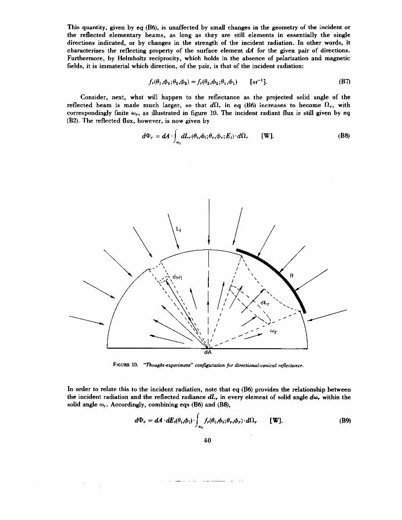
This quantity, given by eq (B6), is unaffected by small changes in the geometry of the incident or the reflected elementary beams, as long as they are still elements in essentially the single directions indicated, or by changes in the strength of the incident radiation. In other words, it characterizes the reflecting property of the surface element dA for the given pair of directions. Furthermore, by Helmholtz reciprocity, which holds in the absence of polarization and magnetic fields, it is immaterial which direction, of the pair, is that of the incident radiation:
Consider, next, what will happen to the reflectance as the projected solid angle of the reflected beam is made much larger, so that dfl, in eq (B6) increases to become Rr, with correspondingly finite wr, as illustrated in figure 10. The incident radiant flux is still given by eq (B2). The reflected flux, however, is now given by
FIGURE 10. “Thought+?zperiment” con&uratwn for directionul-conical rej7ectance.
In order to relate this to the incident radiation, note that eq (B6) provides the relationship between the incident radiation and the reflected radiance dLr in every element of solid angle dw, within the solid angle w,. Accordingly, combining eqs (B6) and (BQ,
40

The directional-conical reflectance is then obtained by combining eqs (15), (B2), and (B9):
in agreement with table 1. The same result can be obtained quite directly by rearranging and integrating the first line of eq (B6):
p(oi,+i;wr) = i, dp(oi,+i;Or,+r)
(B loa)
However, we presented the first derivation because this second approach, although mathematically simpler, may leave some doubt whether the mathematics adequately represents the physics of the situation.
Now, returning to the original configuration with two small holes, consider, instead, what happens if the hole for the incident beam is enlarged substantially, so that dSli in eqs (Bl) and (B5) is increased to Q, with corresponding finite mi. As depicted in figure 11, the resulting reflected radiance Lr(Or,&) is made up of contributions (see eq. (B6))
dA
FIGURE 11. “Thought-experimnt” configuration for conicaldirectional reflectance.
41
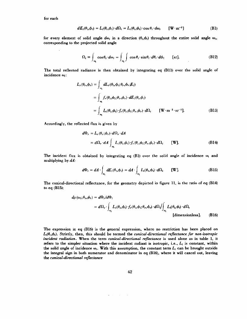
for each
for every element of solid angle dwi in a direction (8{,&) throughout the entire solid angle wi, corresponding to the projected solid angle
The total reflected radiance is then obtained by integrating eq (B11) over the solid angle of incidence mi :
Lr(er,+r) = J d~r(oi,+i;er,+r$i) 01
= J, fr(ei,+i;ert+r) *dEi (ei,+i)
Accordingly, the reflected flux is given by
dQr = Lr(Br;+,).dR, *dA
The incident flux is obtained by integrating eq (BI) over the solid angle of incidence wi and multiplying by dA:
dQi = d~ Jil ai(ei,+i) = d~ . J Li(ei,+i) .dai WI. (B15) "I
The conical-directional reflectance, for the geometry depicted in figure 11, is the ratio of eq (B14) to eq (B15):
The expression in eq (B16) is the general expression, where no restriction has been placed on Li(Oi,+i). Strictly, then, this should be termed the conicaldirectional reflectance for non-isotropic incident radiation. When the term conicaldirectional reflectance is used alone as in table 1, it refers to the simpler situation where the incident radiant is isotropic, i.e., Lf is constant, within the solid angle of incidence wf. With this assumption, the constant term Li can be brought outside the integral sign in both numerator and denominator in eq (B16), where it will cancel out, leaving the conicaldirectional reflectance
42

again in agreement with table 1. From eqs (B1O) and (B17) it can be seen that, over a finite solid angle of reflection w, , the value
of reflectance is obtained by integrating the bidirectional reflectance-distribution function f r ( O i , 4 i ; O r , + r ) with respect to projected solid angle do, over that solid angle w, and, over a finite solid angle of incidence mi, it is obtained by averaging f r (Oi ,4 i ;Or ,+r ) with respect to projected solid angle doi over that solid angle wi. We can, then, combine these two operations to obtain the general expression for the biconical reflectance
As previously pointed out, this is the completely general expression for all geometries if we assume that the solid angle dw 5 w 5 27r [sr] for both wi and w,. Hence, all of the expressions in table 1 may be derived from eq (B18) by substituting the corresponding values for these solid angles. Note, however, this is not completely general, in the sense that it is based on the assumption of isotropic irradiance within the solid angle of incidence wi. The more general expression, for non-isotropic incidence, is that given earlier in eq (15a).
VIII. Appendix C. Perfectly Diffuse and Perfectly Specular Reflectances
Perfectly Di,ffuse Reflectance
A perfectly diffuse or “lambertian” surface element dA is one for which the reflected radiance is isotropic so that L , is a constant, with the same value for all directions (Or,&), regardless of how it is irradiated. From eq (B13) it is apparent that this is possible only when f , =
f r ,d a constant, so that
hence
In terms of the perfectly diffuse reflectance pd, which is the fraction of the total incident flux that is reflected isotropically (iso-radiance rays) in all directions (into the full hemisphere above the element dA of the reflecting surface), we have
= fr,d ( O i , 4 i ; O r , + r ) *?r [dimensionless];
hence
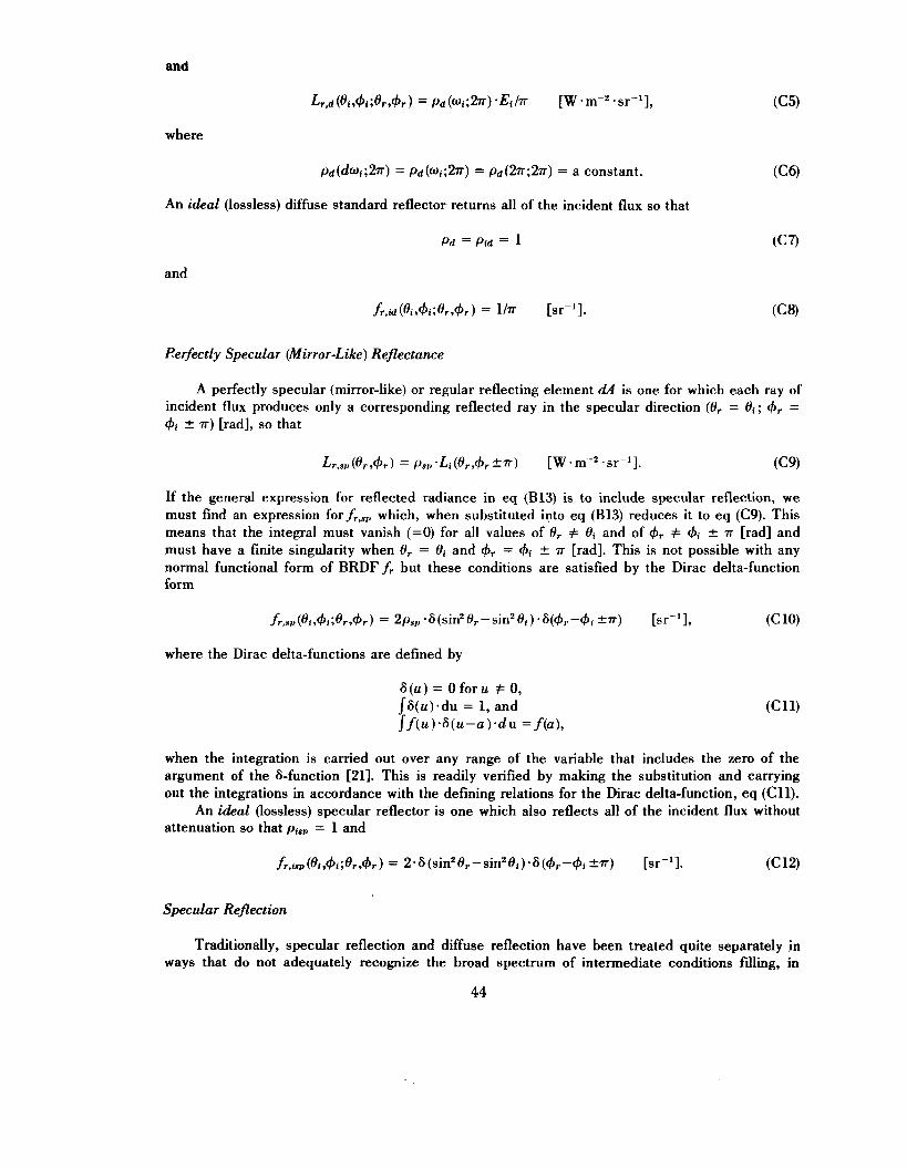
and
where
An ideal (lossless) diffuse standard reflector returns all of the incident flux so that
and
Perfectly Specular (Mirror-Like) Reflectance
A perfectly specular (mirror-like) or regular reflecting element a54 is one for which each ray of incident flux produces only a corresponding reflected ray in the specular direction (0, = 0i; 4, = 4i 2 7 ~ ) [rad], SO that
If the general expression for reflected radiance in eq (B13) is to include specular reflection, we must find an expression forfr,sr, which, when substituted into eq (B13) reduces it to eq (C9). This means that the integral must vanish ( = O ) for all values of 0, # 0i and of 4,. # c#+ 2 7~ [rad] and must have a finite singularity when 0,. = 0i and 4,. = di f 7~ [rad]. This is not possible with any normal functional form of BRDF f, but these conditions are satisfied by the Dirac delta-function form
where the Dirac delta-functions are defined by
when the integration is carried out over any range of the variable that includes the zero of the argument of the &function [21]. This is readily verified by making the substitution and carrying out the integrations in accordance with the defining relations for the Dirac delta-function, eq (C11).
An ideal (lossless) specular reflector is one which also reflects all of the incident flux without attenuation so that pisp = 1 and
Specular Reflection
Traditionally, specular reflection and diffuse reflection have been treated quite separately in ways that do not adequately recognize the broad spectrum of intermediate conditions Mling, in
44
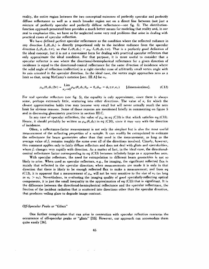
reality, the entire region between the two conceptual extremes of perfectly specular and perfectly diffuse reflectance as well as a much broader region not on a direct line between (not just a mixture of perfectly specular and perfectly diffuse reflectance-see fig. 5). The distribution- function approach presented here provides a much better means for modeling that reality and, in our zeal to emphasize this, we have so far neglected some very real problems that arise in dealing with practical cases of specular reflection.
We have Pefined perfect specular reflectance as the condition where the reflected radiance in any direction L,(O,,+,) is directly proportional only to the incident radiance from the specular direction Li(Orr+,?~), so that L,(O,,&) = psp-Li (Or ,+ ,kr) . That is a perfectly good definition of the ideal concept, but it is not a convenient form for dealing with practical specular reflectors that only approximate the ideal condition. For that purpose, it is more useful to consider that a specular reflector is one where the directional-hemispherical reflectance for a given direction of incidence is equal to the directional-conical reflectance for the same direction of incidence where the solid angle of reflection (collection) is a right circular cone of arbitrarily small vertex angle with its axis oriented in the specular direction. In the ideal case, the vertex angle approaches zero as a limit so that, using McCamy’s notation [sec. III.A] for w,.
For real specular reflectors (see fig. S), the equality is only approximate, since there is always some, perhaps extremely little, scattering into other directions. The value of K, for which the closest approximation holds true may become very small but will never actually reach the zero limit for obvious reasons. Some of those reasons are mentioned briefly in commenting on figure 5 and in discussing glossimetry practices in section 1II.C.
In any case of specular reflection, the value of ps,, in eq (C10) is that which satisfies eq (C13). Hence, i t should probably be written as P ~ ~ , ( O ~ , + ~ ) in eq (ClO), since it may vary with the direction of incidence.
Often, a reflectance-factor measurement is not only the simplest but is also the most useful measurement of the reflecting properties of a sample. It can readily be extrapolated to estimate the reflectance for beam geometries other than that used in the measurement, as long as the average value off, remains roughly the same over all of the directions involved. Clearly, however, this comment applies only to fairly diffuse reflectors and does not deal with glints and specularities, wheref, changes very rapidly with direction. As a matter of fact, in the ideal case, the directional- conical reflectance factor corresponding to eq (C13) becomes infinitely large as K approaches zero.
With specular reflectors, the need for extrapolation to different beam geometries is not so likely to arise. When used as specular reflectors, e.g., for imaging, the significant reflected flux is mainly that reflected in the specular direction; when measurements are made it is only in that direction that there is likely to be enough reflected flux to make a measurement; and from eq (C13), it is apparent that a measurement of psp will not be very sensitive to the size of Or (as long as w, > wi). Nevertheless, in evaluating the imaging quality of good specularly-reflecting optical components, it is just the small inequality in the approximation of eq (C13) that is significant. It is the difference between the directional-hemispherical reflectance and the specular reflectance, the fraction of the incident radiation that is scattered into directions other than the specular direction, that produces veiling glare to degrade image contrast.
OfjSpecular Peaks or “Glints”
One further complication that can arise in connection with specular reflection concerns the occurrence of off-specular peaks or “glints” [35]. However, our approach can accomodate them quite easily [36].
45

First, the delta-function form of the BRDF for perfectly specular reflectance can be adjusted for such off-specular peaks. If, for example, a specular peak or glint is observed, for an unusual reflecting surface, at 8, = 8i & (Y and +r = 4, f p, that condition can be represented by a delta- function component of the BRDFf, as follows:
fr = 2.ps, .6[sin28, - ~in'(8~&a)].6[+, - (+if/3)] [sr-'1 (C 14)
and, again, the value of psp may vary with &,+i and, possibly, with Or,+, as well, since we have shown two possibilities for each incident direction angle with the plus-or-minus signs, so, for complete generality, we probably should write psp = p8,(8i,+i;8,,+,) in eq (Cl4).
A similar adjustment of the expression in McCamy's notation in eq (C13) is quite straightfor- ward.
For real reflecting surfaces, since no limitations have been placed on the form of the BRDF fr(Oi,+i;Or,+r), it is obviously possible to express it in any way that will serve a useful purpose. Measurement results can be just a table of values at appropriate parameter intervals, with, possibly, smaller intervals in the vicinity of sharp peaks or other rapid changes in value, to facilitate interpolation where required. For some purposes it may be useful to approximate these values by a curve for an analytic function, if one can be found to serve. Such a function may turn out to be,the sum of two or more functions, one function for a continuous diffuse distribution and one or more functions (possibly, delta functions, if the peaks are sharp enough) for the specular peak(s) or glint(s). There is no limit to the possibilities.
IX. Appendix D. Details for Derivation of McCamy's Notation
Quite frequently, an element of reflecting surface dA is located at the focus of circular optics, so that the beam is a right circular cone with its vertex at &I. This may be true for either, or both, the incident and/or the reflected beam, as depicted in figure 4. The solid angle formed by and containing such a beam can be specified completely by giving the angular-direction coordinates (80,+o) of the axis along with the half-vertex angle K , as in figure 4. However, in order to use this notation, as proposed by McCamy [13], we need to be able to write the expressions for biconical reflectance p (8Oi1+Oi,Ki;8Or,~Or,Kr) and for biconical reflectance factor R (8Oir+Oi,Ki;8or,+Or,Kr) in terms of the BRDFfr(8i,+i ;Or,+,) corresponding, respectively, to eqs (16) and (18).
Consider a right circular cone, of half-vertex angle K , with its vertex at the origin 0 and its axis tilted in the direction (80,+o) as in figure 12. A point Po on its axis then has the coordinates14 (1Do,80,+o) in the fixed system of spherical coordinates with the X-Y plane tangent to the surface element d A at 0 and the Z-axis along the normal to d A . A plane through Po perpendicular to the axis of the cone, cuts the cone in a circle of radius r = po-tanK. A point P on this circle has the coordinates (p,8,+), as depicted in figure 12.
Consider, also, a second, tilted set of spherical coordinates, with the same origin 0, and with the new polar axis (the 2'-axis) along the axis of the cone. The new polar angle 8' is the angle from that axis and, for any point P on the surface of the cone, 8' = K . The X'-axis may be arbitrarily chosen+.g., to lie as shown along the line of intersection between the X-Y plane and the tilted X'-Y' plane. Then, in the new tilted (primed) spherical coordinates, the point P on the circle bounding the base of the right circular cone of half-vertex angle K , has the coordinates @',8',+') = @,K,+') . (See fig. 12.)
The solid anglew enclosed by the cone at its vertex 0 is easily evaluated by eq (A2-lo), p. 70, of [2] since 8, = K :
" This use o f p as a spherical coordinate is confined just to appendix D. Since. when so used, p is always explicitly designated as a spherical coordinate or is enclosed in parentheses dong with one or both of the other spherical coordinates (e,+). there should be no confusion with the use of p for reflectance.
46
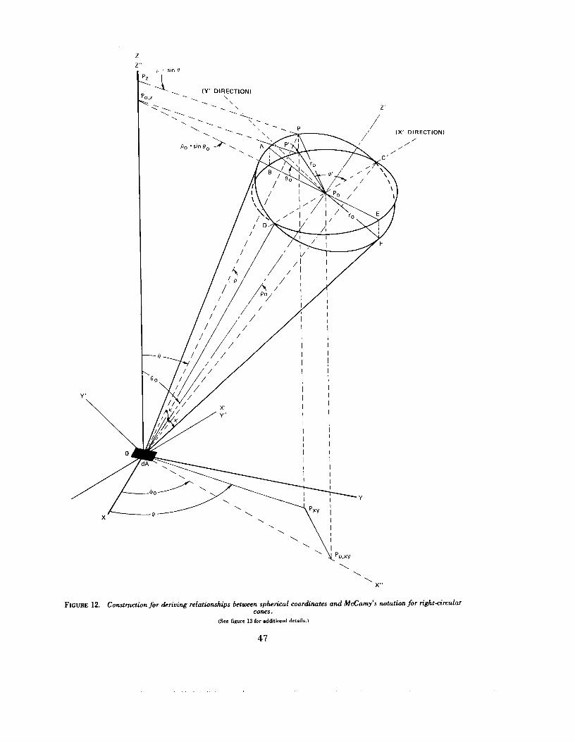
z 2''
p . sin 0
- , I Y ' DIRECTION) . \ .
DIRECTION) /
/
\ \ \
X"
FIGURE 12. Construction for deriving relationships between spherical coordinates and McCamy's notation for right<ircular cones.
(See figure 13 for additional details.)
47
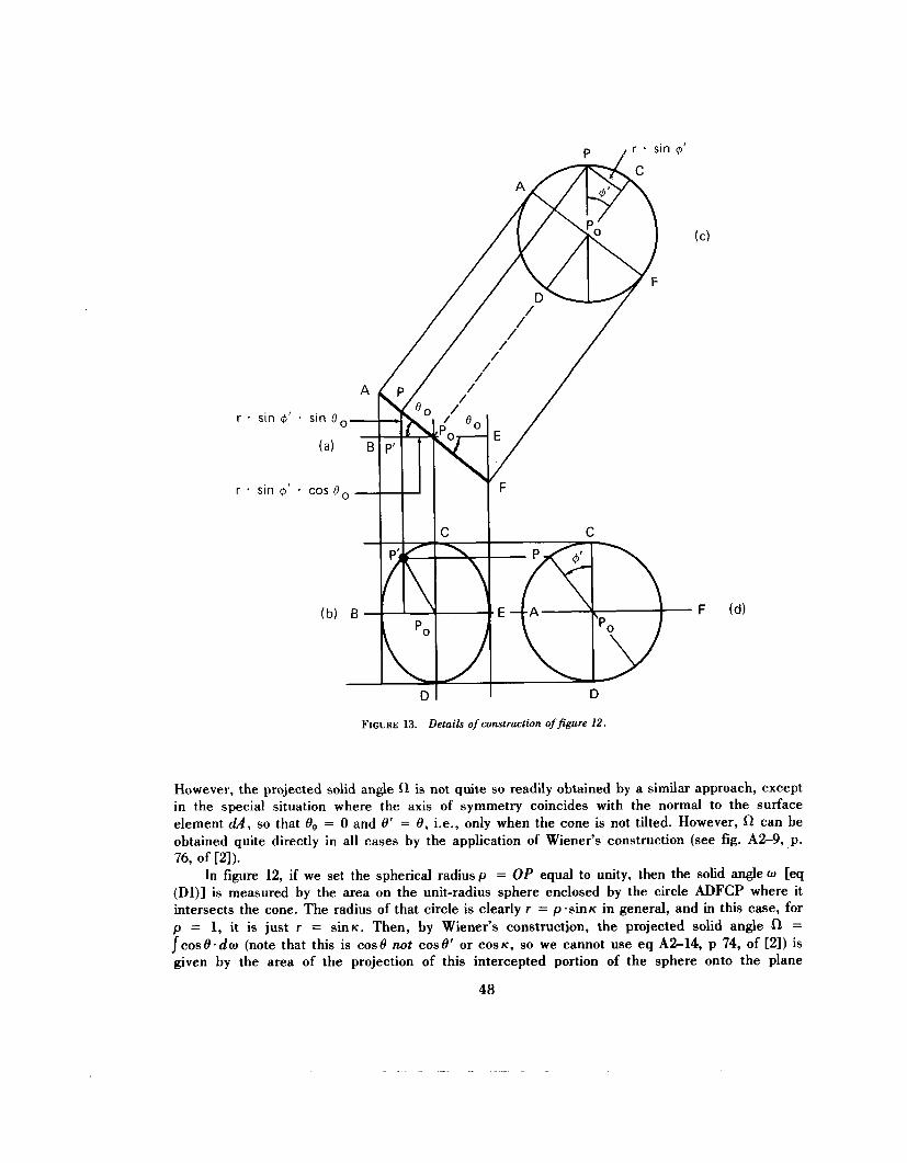
, r sin @’
r - sin $’ . sin 8
I D
FIGURE 13. Details of construction of&re 12.
However, the projected solid angle R is not quite so readily obtained by a similar approach, except in the special situation where the axis of symmetry coincides with the normal to the surface element dA, so that 8, = 0 and 8’ = 8, i.e., only when the cone is not tilted. However, R can be obtained quite directly in all cases by the application of Wiener’s construction (see fig. A2-9, ,p. 76, of [2]).
In figure 12, if we set the spherical radius p = OP equal to unity, then the solid angle w [eq (Dl)] is measured by the area on the unit-radius sphere enclosed by the circle ADFCP where it intersects the cone. The radius of that circle is clearly r = pas in^ in general, and in this case, for p = 1, it is just r = sinK. Then, by Wiener’s constructjon, the projected solid angle 0 = J c o s 8 . d ~ (note that this is cos8 not cos8’ or COSK, so we cannot use eq AZ14, p 74, of [2]) is given by the area of the projection of this intercepted portion of the sphere onto the plane
48

containing the element dA, i.e., by the area of the projection of the circle ADFCP onto that plane (The X-Y plane). It is readily seen in figure 12 that this will be the same as the area of the ellipse BDECP’, the projection of the circle ADFCP onto a horizontal plane parallel to the X - Y plane. The area of the ellipse is clearly just cosOo times the area of the circle, which, in turn, is given by 7~ . r so that we can write
for the projected solid angle subtended at dA by a right circular cone of half-vertex-angle K with its vertex at dA and its axis tilted at an angle Bo from the normal to dA.
With these preliminary statements for o and R, we are now ready to attack the main problem of expressing and evaluating biconical reflectance in McCamy’s notation. We start with the general relation
First, from eq (D2), we can write Oi = T . cosOOi. s inki . Next, if the usual order of integration is reversed, the extreme limits for the full range of 8 (both O i and 0,) are clearly O 0 + ~ and H O - ~ . Finally, the limits of integration for + (both ( p i and 4,) will be a function of (the corresponding) 8. In each case, the first integration, with respect to +, will be along lines of constant 0 (parallels of “latitude,” parallel to the X -Y plane) between the limits where they cut the circle ADFCP (see fig. 12). These limts, then, are clearly symmetrical about the value +@ so that they can be written as +,+a(8) and +o-a(8). Before deriving an expression for the function a(@, we can now summarize the foregoing by writing the biconical reflectance, in terms of McCamy’s notation and the function a(@, as
In order to evaluate the function a(O), we need to determine the equation of the circle ADFCP (fig. 12). This task can be simplified considerably by eliminating We set 40’’ = 0, which is equivalent to rotating the fixed X-Y axes about the Z-axis to bring the X-axis into the same “vertical” plane as the axis of the tilted cone (so that the X-Y axis now lies in the “vertical” X-Z plane). Quantities given in the new rotated coordinates will be distinguished by a double prime; thus, the rotated coordinates of the point Po on the axis of the cone are
Po” = pa; 8,” = eo; 40’’ = 0; etc.
In general, the equation of a plane through a point Po and perpendicular to the line 04 [=pa = (x: + y: + z:)r], with direction cosines
49
is
lx + my + nz = po = p*cosp , (D3)
wherep is the angle between the line OPo and the line OP, and P is any point (x,y,z) in the plane. Ifp = K and the value of p are both fixed, we have the equation of the circle ADFCP (fig. 12) as
because, with + O t r = 0, yo“ = potr-sin00.sin40“ = 0 so that mR = 0. Then 1” = sinOOn and nf‘ = COSO,,”, and the values of 4” for points on the circle that satisfy these relations are the desired expressions for the function a (0 ). From eq (D4)
and
COS^" = (cos K - n”.cos0”)/(1”.sin0”)
hence the desired limits are, recalling that 0” = .e,
When this expression for a(0) is inserted in eq (20), we have the desired expression for biconical reflectance in terms of the BRDF, all in McCamy’s notation for right-circular-conical beams.
In the same way we can obtain, from eq (18), the expression for a biconical reflectance factor, as in eq (22).
X. Acknowledgments
The authors wish to express their sincere thanks for their support from a variety of sources since this effort started in 1967: Infrared Information and Analysis Center15 under ONR contract and Target Signature Analysis Center under USAF Avionics Lab. contract (Limperis, Ginsberg, and Nicodemus); Sylvania Electronics Systems Western Division under U.S. Army Electronics Command contract, Cintra, and U.S. Naval Weapons Center (Nicodemus); National Bureau of Standards (Nicodemus, Richmond and Hsia).
In all of this time, portions of this material have been presented or circulated, with resulting comments and criticisms from a great many helpful individuals to whom we are very much indebted. Our efforts were first announced and discussed at the meeting of the Optical Society of America, Technical Group on Radiometry and Photometry, in Detroit, Michigan, in October 1967. Acknowledgment is due to Applied Optics for publishing the letter to the editor by Nicodemus [9] to clarify some urgent matters when it was apparent in 1970 that the full paper would still be substantially delayed. He also informally circulated rather widely a summary of much of this material in a draft intended as part of a Cintra report (that was never published). More recently, in January 1973, he reported on our efforts to the IRIS Specialty Group on Infrared Standards, at Huntsville, Alabama. We are deeply grateful for all of the suggestions, criticisms, and comments
1
‘I Willow Run Laboratories. University of Michigan (now Environmental Research Institute of Michigan).
that have resulted from these and other individual exchanges and we regret our inability to make individual acknowledgments in so very many instances.
We are particularly grateful to Dr. G. J. Zissis and his staff at the IRIA Center, Environmental Research Institute of Michigan (ERIM), for making available the small figures used to illustrate table 3. And finally, we acknowledge the very extensive review and criticism by W. H. Venable, who made substantial contributions to our efforts.
XI. References
[l] The term “propagance” for this useful concept, the ratio of received radiance at a receiver to the emitted radiance along the same ray at the source, was suggested by C. S. McCamy [13]. It is also defined and discussed in [2]; see esp. eqs (2.37) and (2.38) and accompanying discussion.
[2] Part I. Concepts, Chapters 1-3, of [28], Nat. Bur. Stand. (U.S.), Tech. Note 910-1, 93 pages (March 1976). 131 The terms “attenuance” and “vcatterance” for these useful ratio concepts, which we prefer to define, like propagance,
in terms of single rays or elements of throughput by taking the ratios of radiances, are widely used by oceanographers; see N. G. Jerlov, Optical Oceanography (Elsevier Publishing Co.. New York, 1968), esp. pp. 6 & 7.
[4] ANSI Standard Nomenclature and Definitions for Illuminating Engineering, ANSI 27.1-1%7 (Revision of 27.1-1942). RP-16, approved August 16, 1967, by American National Standards Institute, sponsored and published by Illuminating Engineering Society, 345 East 47th Street, New York, N.Y. 10017. See also Appendix 1 of [2].
[5] Nicodemus, Fred E., Radiometry, Chapter 8 in Volume IV of Applied Optics and Optical Engineering, R. Kingslake, Ed. (Academic Press, New York, 1967); also included in [37].
161 Planck, Max, The Theory of Heat Radiation, trans. by Morton Masius (Dover Publications, Inc., New York, 1959). Part I, Chapter I, pp. 1-21.
[7] Jones, R. Clark, Appendix [on Radiometry] in: I. F. Spiro, R. Clark Jones, and D. Q. Wark, Atmospheric Transmission: Concepts, Symbols, Units and Nomenclature, Infrared Physics, 5, No. 1, March 1965, pp. 11- 36. (With the help of Dr. Jones, a number of unfortunate typographical errors were corrected for its reproduction in C37l.l
[SI Venable, William H., Jr., and Hsia, Jack J., Describing Spectrophotometric Measurements, Nat. Bur. Stand. (U.S.), Tech. Note 594-9, November 1974.
[9] Nicodemus, Fred E., Reflectance Nomenclature and Directional Reflectance and Emissivity, Appl. Optics 9, No. 6, June 1970, pp. 1474-1475 also included in [37].
[lo] Nicodemus, Fred E., Directional Reflectance and Emissivity of an Opaque Surface, Appl. Optics 4, No. 7, July 1965, pp. 767-773; Erratum, Appl. Optics 5, No. 5, May 1966, p. 715.
[ll] Chandrasekhar, S., Radiative Transfer (Dover Publications, Inc., New York, 1960). [12] Judd, Deane B., Terms, Definitions, and Symbols in Reflectometry, J. Opt. SOC. Am. 57, No. 4, April 1967, pp. 445-
4.52. [13] McCamy, C. S., Concepts, Terminology, and Notation for Optical Modulation, Photographic Science and Engineering
10, No. 6, November-December, 1966, pp. 314-325. [14] International Lighting Vocabulary-3rd Edition (common to the CIE and IEC), Intemational Commission on Illumination
(Commission Internationale de I’Eclairage-CIE), Bureau Central de la CIE, 4 Av. du Recteur Poincak, 75-Paris 16e, France; Publication CIE No. 17 (E-1.1) 1970. (The IEC is the Intemational Electrotechnical Commission.)
[E] Tentative Method of Test for Specular Gloss, Federation of Societies for Paint Technology Standard No. Le-564, ASTM Designation: D523-62T. Issued 1953, Revised 1962, American Society for Testing and Materials (1965 Book of ASTM Standards, Part 21, pp. lW112).
[16] Hammond, Harry K., 111, and Nimeroff, Isadore. Measurement of Sixty-Degree Specular Gloss, J. Res. Nat. Bur. Stand. (U.S.), 44, June 1950, pp. 585598 Research Paper RP2105.
[la Nimeroff, Isadore, Analysis of Goniophotometric Reflection Curves, J. Res. Nat. Bur. Stand. (U.S.), 48, No. 6, June 1952, pp. 4 4 1 4 Research Paper RP2335; also a less extended treatment in J. Opt. SOC. Am. 42, No. 8, August 1952, pp. 57e583.
1181 Kneissl, Gerhart J., and Richmond, Joseph C., A Laser-Source Integrating Sphere Reflectometer, Nat. Bur. Stand. (US.), Tech. Note 439 (February 1968).
[19] DeVos, J. C., Evaluation of the Quality of a Blackbody, Physica, 20, No. 10 (October 1954) pp. 669-689. [ZO] Trowbridge T. S., and Reitz, K. P., Average irregularity representation of a rough surface for ray reflection, J. Opt.
[21] Bracewell, Ron, The Fourier Transform and Its Applications (McGraw-Hill Book Co., New York, 1965) Chapter 5, The
C221 Kubeka, Paul, New Contributions to the Optics of Intensely Light-Scattering Materials. Part I, J. Opt. Soc. Am. 38,
Soc. Am. 69, No. 5 (May 1975) pp. 531-536.
Impulse Symbol.
No. 5, (May 1948) pp. 448-457; ERRATA, 38, No. 12 (Dec. 1948) p. 1067.
51
1231 Hamaker, H. C., Radiation and Heat Conduction in Light-Scattering Material, Philips Res. Rep. 2 (1947): I. Reflection and Transmission, pp. 55-67; 11. General Equations Including Heat Conduction, pp. 10S111; 111. Application of the Theory, pp. 112-125; IV. Various Extensions and a Generalized Theory, pp. 420-425.
[24] Richmond, Joseph C., Thermal Radiation Properties of Ceramic Materials, Proc. Symposium on Mechanical and Thermal Properties of Ceramics, Gaithersburg, Md., April 1-2, 1968, Nat. Bur. Stand. (U.S.), Spec. Pub. 303 (May 1%9) pp. 12S137; also in Nat. Bur. Stand. (U.S.) Spec. Pub. 300, Precision Measurement and Calibration, 7, Radiometry and Photometry, H. K. Hammond, 111, and H. L. Mason, Eds. (November 1971) pp. 223-235.
[25] Nelson, Richard W., On the Significance of a Simplified Theory of Radiative Transfer, J. Opt. SOC. Am. 62, No. 11 (November 1972) p. 1368, Abstract ThC17 (paper presented at 1972 Annual Meeting of Optical Society of America, San Francisco, Calif., October 1972).
[26] Hsia, Jack J., Optical Radiation Measurements.-The Translucent Blurring Effect-Method of Evaluation and Estimation, Nat. Bur. Stand. (U.S.), Tech. Note 594-12 (October 1976).
[27] Hsia, Jack J. , and Richmond, Joseph C., Bidirectional Reflectometry, Part I. A high resolution laser bidirectional reflectometer with results on several optical coatings, J. Res. Nat. Bur. Stand. (U.S.), 80A (Phys. 81 Chem.), No. 2, (March-April 1976) pp. 189-205; Part 11. Bibliography on Scattering by Reflection from Surfaces, ibid., pp. 207-220.
[28] Self-Study Manual on Optical Radiation Measurements, Fred E. Nicodemus, Ed., in preparation by the Optical Radiation Section, National Bureau of Standards (US.). Chapters are being published first, as completed, a s NBS Technical Notes, Series 91CL.
1291 Shurcliff, William A., Polarized Light (Harvard University Press, Cambridge, Mass., 1%2). [30] Edwards, D. K., and Bevans, J. T., Effect of Polarization on Spacecraft Radiation Heat Transfer, AIAA J. 3, No. 7
[311 Sandus, Oscar, A Review of Emission Polarization, Appl. Optics 4, No. 12 (December 1965) pp. 1634-1642. [321 Jones, R. Clark, Immersed Radiation Detectors, Appl. Optics 1, No. 5 (September 1962) pp. 607-613. [331 Gershun, A., The Light Field, Moscow, 1936 (eng. Trans]. by Moon and Timoshenko, J. Math. Physics, 18, May 1939,
[34] Moon, Parry, The Scientific Basis of Illuminating Engineering (Dover, New York, 1957). 1351 Torrance, K. E., Sparrow, E. M., and Birkebak, R. C., Polarization, Directional Distribution, and Off-Specular Peak
[361 Nicodemus, Fred E., Comment on ‘Current definitions of reflectance’, J. Opt. Soc. Am. 66, No. 3 (March 1976) pp.
1373 Nicodemus, Fred E., Ed., Radiometry-Selected Reprints, American Association of Physics Teachers (AAPT), Stony
[38] Page, Chester H., and Vigoureux, Paul, Eds., The Intemational System of Units (SI), Nat. Bur. Stand. (U.S.), Spec.
(July 1965) pp. 1323-1329.
pp. 51-151).
Phenomena in Light Reflected from Roughened Surfaces, J. Opt. SOC. Am. 56, No. 7 (July 1966) pp. 916-925.
283-285.
Brook, New York, July 1971, (Includes reprints of [5], [I, and [9]:
Publ. 330, 1974 edition, 49 pages (July 1974).
ZI U.S. GOVERNMENT PRINTING OFFICE: 1977 0-236-942
52
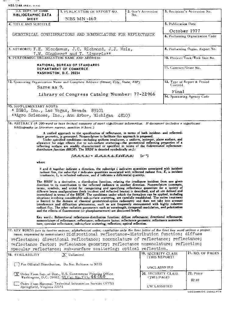
- - - NBS-114A ( R E V . 7-73]
U.S. DEPT. OF COMM. BlBLl OG RAPH IC DATA
1. PUl3I.lC:ATION OR R E P O R T NO. 2. Gov’t Accession 3. Recipient’s Access ion No. No.
SHEET I NBS MN-160 . TITLE AND SUBTITLE
G33KETRICA.L CONSIDERATIONS AND NOMIZNCLATURE FOR REFLECTANCE
5. Publicat ion Date
. AIJTHOR(S) F.E. Nicodemus, J . C . Richmond, J. J. Hsia,
. I-SERFORMING ORGANIZATION NAME AND ADDRESS I . W . Ginsbergw and T. L i m p e r i s * *
NATIONAL BUREAU OF STANDARDS DEPARTMENT OF COMMERCE WASHINGTON, D.C. 20234
8. Performing Organ. Report NO.
10. Project /Task/Work Unit No.
11. Contract /Grant No. 7 1. Sponsoring Organization Name and Complete Address (Street, Ci ty , State, Z I P )
Same as 9. 13. Type of Report tk Period
Covered
L i b r a r y of C o n g r e s s Catalog mumber: 77-22966
Order From National T e c h n i c a l Information Service (NTIS) Springfield, Virginia 22151
5. SUPPLEMENTARY NOTES * EG&G, Inc. , Las Vegas, Nevada 89101 **Agro Sciences, Inc. , Ann Arbor, Michigan 48103
5 . ABSTRACT (A 200-word or l e s s factual summary o f most significant information. I f document includes a significant bibliography or literature survey, mention it here.)
A unified approach to the specification of reflectance, in terms of both incident- and reflected- beam geometry, is presented. Nomenclature to facilitate this approach is proposed.
Under specified conditionsincluding uniform irradiance, a uniform, isotro ic, plane surface. and allowance for edge effects due to subsurface scattering-the geometrical refecling propelties of a reflecting surface are readily characterized or specified in terms of the bidinctional rcflcctance- distribution function (BRDF). The BRDF is denoted symbolically as/,:
h(f4 .&I : H, ,&A 9 dLA% . ~ J I ; Br &,: E,YdEl(O, ,&d ts r- ’ 1 where
0 and d, together indicate a direction, the subscript i indicates quantities asnnciated with incident radiant flux, the subscript r indicates uantities associated with reflected radiant flux. E( is incident irradiance. L. is reflected radiance, an] d indicates a differential quantity.
The BRDF is a derivative, a distribution function, relating the irradiance incident from one given direction to its contribution to the reflected radiance in another direction. Nomenclature (concepts. terms, symbols, and units) for categorizing and specifying reflectance quantities for a variety of different beam configurations (both incident and reflected beams) is described, and all are defined and interrelated in terms of the BRDF. The conditions under which the formalism can be applied, including situations involving considerable sub-surface scattering, are carefully established. The entire treatment is limited to the domain of classical geometrical-optics radiometry and does not take into account interference and diffraction phenomena, such as are frequently encountered with highly coherent radiant flux. The other radiation parameters such as wavelength, (temporal) modulation, and polarization and the effects of fluorescence (or phosphorescence) are discussed briefly.
Key words: Bidirectional reflectance-distribution function: diffuse reflectance; directional reflectance: nomenclature of reflectance; reflectance; reflectance factor: reflectance geometry: reflectance nomencla- ture; specular reflectance; subsurface scattering; reflection; optical reflection.
7. KEY WORDS ( s i x to twelve entries; alphabetical order; capi ta l i ze only the first letter o f the f i rs t key word unless a proper name; separated by semicolons) Bidi rec t iona l re f lec tance-d is t r ibu t ion function; d i f fuse
ref lectance; d i r ec t iona l re f lec tance ; nomenclature of ref lectance; ref lectance; ref lectance f ac to r ; re f lec tance geometry; re f lec tance nomenclature; r e f l ec t ion ;
U N C L ASS1 F I E D
specular ref lectance; sub-surface sca t t e r ing ; o p t i c a l r e f l ec t ion .
(THIS R E P O R T ) 3. AVAILABILITY Unlimited
[? For Off ic ia l Distribution. Do No: R e l e a s e to NTIS I UNCLASSIFIED
a Order From Sup. of Doc., U.S. Government Pr int i Office Washington, D.C. 20402, SD C a t . No. C13. 44:fEO
SECURITY CLASS ( T H I S PAGE)
21. NO. OF P A G E S
22. P r i c e
$2.10
USCOMM-DC 29042-P74
NBS TECHNICAL
PERIODICALS JOURNAL OF RESEARCH-The Journal of Research of the National Bureau of Standards reports NBS research and development in those disciplines of the physical and engineering sciences in which the Bureau is active. These include physics, chemistry, engineering, mathematics, and computer sciences. Papers cover a broad range of subjects, with major emphasis on measurement methodology, and the basic technology underlying standardization. Also in- clude: from time to time are survey articles on topics closely related to the Bureau’s technical and scientific programs. As a special service to subscribers each issue contains complete citations to all recent NBS publications in NBS and non- NHS media. Issued six times a year. Annual subscription: domestic $17.00; foreign $21.25. Single copy, $3.00 domestic; $3.75 foreign. Note: The Journal was formerly published in two sections: Section A “Physics and Chemistry” and Section B “Mathe- matical Sciences.” DIMENSIONS/NBS (formerly Technical News Bulletin)-- This monthly magazine is published to inform scientists, engineers, businessmen, industry, teachers, students, and consumers of the latest advances in science and technology, with primary emphasis on the work at NBS. The magazine highlights and reviews such issues as energy research, fire protection, building technology, metric conversion, pollution abatement, health and safely, and consumer product per- formance. In addition, it reports the results of Bureau pro- grams in measurement standards and techniques, properties of matter and materials, engineering standards and services, instrumentation, and automatic data processing.
Annual subscription: Domestic, $12.50; Foreign $15.65
NO N PER IO Dl CALS MonographsMajo r contributions to the technical liter- ature on various subjects related to the Bureau’s scientific and technical activities. HandbooksRecommended codes of engineering and indus- trial practice (including safety codes) developed in coopera- tion with interested industries, professional organizations, and regulatory bodies. Special Publications-Include proceedings of conferences sponsored by NBS, NBS annual reports, and other special publications appropriate to this grouping such as wall charts, pocket cards, and bibliographies. Applied Mathematics Series-Mathematical tables, man- uals, and studies of special interest to physicists, engineers, chemists, biologists, mathematicians, computer programmers, and others engaged in scientific and technical work. National Standard Reference Data Series-Provides quanti- tative data on the physical and chemical properties of materials, compiled from the world’s literature and critically evaluated. Developed under a world-wide program co- ordinated by NBS. Program under authority of National Standard Data Act (Public Law 90-396).
PUBLl CATIONS
NOTE: At present the principal publication outlet for these data is the Journal of Physical and Chemical Reference Data (JPC’RD) published quarterly for NBS by the Ameri- can Chemical Society (ACS) and the American Institute of Physics (AIP). Subscriptions, reprints, and supplements available from ACS, 1155 Sixteenth St. N.W., Wash., D.C. 20056. Building Science SeriesDisseminates technical information developed at the Bureau on building materials, components, systems, and whole structures. The series presents research results, test methods, and performance criteria related to the structural and environmental functions and the durability and safety characteristics of building elements and systems. Technical No tesS tud ie s or reports which are complete in themselves but restrictive in their treatment of a subject. Analogous to monographs but not so comprehensive in scope or definitive in treatment of the subject area. Often serve as a vehicle for final reports of work performed at N HS under the sponsorship of other government agencies. Voluntary Product Standards-Developed under procedures published by the Department of Commerce in Part 10, Title 15, of the Code of Federal Regulations. The purpose of the standards is to establish nationally recognized require- ments for products, and to provide all concerned interests with a basis for common understanding of the characteristics of the products. NBS administers this program as a supple- ment to the activities of the private sector standardizing organizations. Consumer Information Series-Practical information, based on NBS research and experience, covering areas of interest to the consumer. Easily understandable language. and illustrations provide useful background knowledge for shop- ping in today’s technological marketplace. Order above NBS puhlicutions from: Supcrintendent of Documents, Government Printing Ofice, Washington, D.C. 20402. Order following NBS publicutions-NBSIR’s and FIPS f r o m the National Technical Information Services, Springfield, V a . 2 2 / 6 1 . Federal Information Processing Standards Publications (FIPS PUB )-Publications in this series collectively consti- tute the Federal Information Processing Standards Register. Register serves as the official source of information in the Federal Government regarding standards issued by NBS pursuant to the Federal Property and Administrative Serv- ices Act of 1949 as amended, Public Law 89-306 (79 Stat. 1127), and as implemented by Executive Order 11717 (38 F R 12315, dated May 11, 1973) and Part 6 of Title 15 CFR (Code of Federal Regulations). NBS Interagency Reports (NBSIR)--A special series of interim or final reports on work performed by NBS for outside sponsors (both government and non-government). In general, initial distribution is handled by the sponsor; public distribution is by the National Technical Information Services (Springfield, Va. 22161) in paper copy or microfiche form.
BIBLIOGRAPHIC SU BSCRl PTlON SERVICES
The followine current-awareness and literature-survey bibli- Superconducting Devices and Materials. A literature survey ~~ - -
issued quarterly. Annual subscription: $30.00. Send subscrip- ographies are issued periodically by the Bureau: Cryogenic Data Center Current Awareness Service. A litera-
ture survey issued biweekly. Annual subscription: Domes- tion orders and remittances for the preceding bibliographic services to National Bureau of Standards, Cryogenic Data
Center (275.02) Boulder, Colorado 80302.
tic, $25.00; Foreign, $30.00. Liquified Natural Gas. A literature survey issued quarterly. Annual subscription: $20.00.
.. ..., . , . . ,‘. . . . . ._ . . . .. “ . ,i . . ” , / . _ _ . . .. .-. .. , . / . .- ”

U.S. DEPARTMENT OF COMMERCE National Bureau of Standards Washington. O.C. 20234
7
OFFICIAL BUSINESS
Penalty for Private Use. $300
POSTAGE AND FEES PAID U.S. DEPARTMENT OF COMMERCE
COM-21s
SPECIAL FOURTH-CLASS RATE BOOK