geometry clean-up in numerical simulationscfdyna.com/notes/pre/geomdefeature.pdf · geometry...
TRANSCRIPT

Geometry Clean-up in
Numerical Simulations

The guidelines are very generic in nature and has been explained with examples.
However, the users may need to check their software user manual to understand
all the features available.
1. Why geometry cleaning is required?
2. Basic operations of geometry clean-up tools
3. Examples
What happens when geometry information is translated from CAD format to a neutral file format? The
answer to this question will require a knowledge of not only the way CAD data are stored but also the
universal way (read mathematics) to store the geometrical information such as lines and curves. The most
natural way to make a design is to use “regular curves” such as straight lines, circle and arcs, ellipses.
However when the same information is translated into a neutral format say IGES, they are recorded into
a more universal way of representing the curves ‘Spline’ and ‘NURBS’!
Scope of the this Presentation

Geometry Clean-up: A Prelude
Geometry clean-up or defeaturing is an inevitable activity of most of the numerical simulations. This
extra activity may be required to simplify the CAD geometry by deleting the spurious details from
Numerical Simulation point of view or to compensate for the data loss that might arise during the data
conversion form CAD-kernel to FE-Kernel. There are two international neutral formats widely
recognized and used for data transfer from native CAD format namely IGES (International Graphics
Exchange Standard - American standard) and STEP (STandard for Exchange of Product model data - a
European Standard).
The understanding of mathematical description and storage of geometrical entities by CAD kernels
and FE-kernels will help the two set of engineers to smoothen the process. But, it may not be
completely eliminated. Lot of resources are being allocated by the software development vendors to
minimize or eliminate the data loss that may arise during geometry data translation. This article is
aimed at:
1. Compiling all nomenclature and geometric transformation available in contemporary CAD and FE
GUIs

2. Developing a comparative summary of defeaturing methods available in various meshing softwares
3. Making a summary of mathematical operations being used in data creation, translation and their
limitations
4. Preparing Best Practice Guidelines for Design Engineers, CAD Operators and FE Analysts to
minimize the "Defeaturing" efforts.
The information collected below is in nascent stage and lot of efforts is being put to make it a
comprehensive and reliable resource on the subject. Any comments and feedback are welcome!
Geometry Clean-up: A Prelude

Geometry Clean-up: Summary of Features
OPERATION/DESCRIPTION ANSYS HM ICEM GAMBIT
Shared Edge, attached to 2 surf. GRN GRN RED BLU
Non-manifold Edge RED YLO BLU RED
Suppressed Edge/Curve x BLU Not Visible x
Topology Correction Nomenclature x Geom Clean-
up Build
Geometry x
Line Collapse √ x X √
Create Lines √ √ √ √
Connect Vertices √ √ √
Trim Curves √ √ √ √
Split/Break Curves √ √ √ √
Extend Curves x x √ √
Bridge Curves x x √ √
Join Curves x x √ √
Equivalence x √ √ x
Edge Re-trim (ICEM)/Edge Toggle (HM) √ x √ x
Line Merge √ √ √ √
Area Merge √ √ √ √
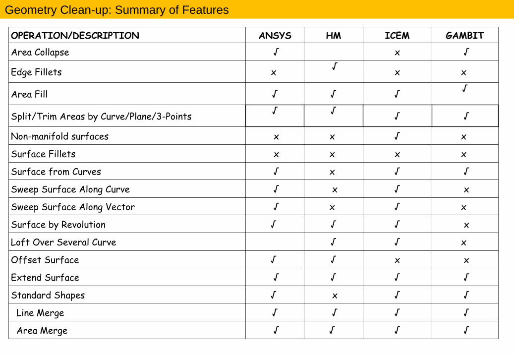
OPERATION/DESCRIPTION ANSYS HM ICEM GAMBIT
Area Collapse √ x √
Edge Fillets x √
x x
Area Fill √ √ √ √
Split/Trim Areas by Curve/Plane/3-Points √
√
√ √
Non-manifold surfaces x x √ x
Surface Fillets x x x x
Surface from Curves √ x √ √
Sweep Surface Along Curve √ x √ x
Sweep Surface Along Vector √ x √ x
Surface by Revolution √ √ √ x
Loft Over Several Curve √ √ x
Offset Surface √ √ x x
Extend Surface √ √ √ √
Standard Shapes √ x √ √
Line Merge √ √ √ √
Area Merge √ √ √ √
Geometry Clean-up: Summary of Features
Geometry Clean-up: Virtual Topology
Virtual Topology: A virtual entity doesn't have a geometric definition of its own, but is based on other
entities. Virtual topological entities are (a) Surface Trim or split (b) Surface merge, etc. GAMBIT, FEMAP,
HM supports this concept. ICEM does not follow this concept even though they support the operations of
surface trim, merge, suppress, etc.

Geometry Clean-up: References from Softwares - Ansys

Geometry Clean-up: References from Softwares - Ansys

Geometry Clean-up: References from Softwares - Hypermesh
Remove Interior Holes Remove Small Fillets
A powerful technique for finding problem areas is to use
the auto-mesh panel in interactive mode to preview a
mesh on the surfaces. Use your target element size and
review areas with a node density of 1. These are an
indication that the feature may be too small for the
element size you plan on using. This helps identify short
surface edges to be suppressed or any fixed points that
should be combined.

An incongruency problem means that two (or more) surfaces, appearing to have an edge in common, do
not share same edge vertices.
1. Two points are coincident if they are separated by a distance equal to or less than the global model
tolerance. If, upon creation, two points are coincident, they are considered the same and the
second point is not created.
2. Two surfaces sharing the same edge are topologically congruent. Similarly, any two surfaces not
separated by a distance greater than the global model tolerance are considered to be the same and
only one is created.
3. Two solids sharing the same face are topologically congruent.
4. When you perform meshing, if the resulting mesh does not match at boundaries between two
surfaces and they appear to be topologically congruent, it is probably because the global model
tolerance was too small at the time the surfaces were created. To prevent this from occurring, we
recommend a tolerance of 0.05% of the expected maximum model size. The correct tolerance may
vary, however, based on the size of the smallest mesh element or geometric entity you plan to
model. If gaps greater than the
Geometry Clean-up: Topological Definition

tolerance exist where geometry should connect, you may need to increase the global model
tolerance. Too large a tolerance value can result in problems with other parts of the model, so
consider carefully before you increase the tolerance.
5. CFX-Build determines connectivity (topology) of the model during the creation phase, or via CAD
access or import of geometry. Once connectivity is determined you cannot modify it unless you
first delete the geometry, change the tolerance and then re-create the geometry.
Geometry Clean-up: Topological Definition

Operation Description UG HM GAMBIT ANSYS ICEM CFX-Build
Rotate MB2 Arrow Keys, r,
(a, MB1) MB1 ^+MB3 MB1
^Z, ^X, ^Y
F2+MB2
F3+MB2
Pan Shift+MB2 ^+MB3 MB2 ^+MB1 MB2 F4+MB2,
Arrows
Zoom ^+MB2 (S, MB1),
^+MB2 MB3 ^+MB2 MB3
z, Z,
F5+MB2
Fit ^+F f GUI GUI GUI ^F
Window Zoom MB1 ^+MB2 ^+MB2, ^+MB1 GUI GUI GUI
Refresh, Replot F5 p GUI GUI GUI GUI
Select, Pick MB1 MB1 Shift+MB1 MB1 MB1 MB1
Deselect, Unpick Shift+MB1 Shift+MB1 Shift+MB2 GUI MB3 MB3
Execute, Apply MB2 MB2 Shift+MB3 MB2 MB2 MB2
Toggle Selection/Operation -- b MB2*MB2 MB3 GUI ---
Align to View F8 -- -- -- Click on Axis --
UNDO ^+Z Not Available GUI Not Available GUI GUI
REDO Not Available Not Available GUI Not Available GUI GUI
Basic Operation: Keyboard Short-cuts and Mouse Button Action

Operation Description UG HM GAMBIT ANSYS ICEM CFX-Build
SAVE ^+S GUI GUI GUI GUI GUI
FILE EXTENSION *.prt *.hm *.dbs
*.jou *.db
*.tin, *.prj,
*.uns,*.blk *.db *.gtm
New Sesion ^+N GUI GUI GUI GUI ^+N
Open ^+O GUI GUI GUI GUI ^+O
Close ^+X GUI GUI GUI GUI ^+W
Revert/Resume Not Available GUI Not Available GUI Not Available Not
Available
Rebuild GUI -- -- -- GUI --
Quit/Exit ^+E GUI GUI ^+E GUI ^+Q
Basic Operation: Keyboard Short-cuts and Mouse Button Action

Geometry Cleanup: Optimize Topology – Hard Points, Surface Edges
These two points are redundant
since the circular edge is good
enough to resolve the local
geometry
These 3 points lie on a
straight line, the middle
one can be deleted
Delete hard points which are not required to guarantee sharp curvature of the computational
geometry. For example, if there are three points on an straight edge, the middle one should
always be deleted. This provides flexibility to the in-build smoothing algorithm.

Geometry Cleanup: Keyboard Shortcuts in ICEM CFD V11.0
Action Geometry, Edit Mesh,
Blocking
Undo ^+Z (Ctrl + Shift + z)
Redo ^+Y (Ctrl + Shift + y)
Scale to Fit x
View-X X =shift+x
View-Y Y
View-Z Z
View Reverse R
View Isometric I
Zoom z
Build Topology b
Delete (Make Dormant) d
Delete Permanently ^+d (Ctrl + d)

Geometry Cleanup: Keyboard Shortcuts in ICEM CFD V11.0
Action Edit Mesh /Blocking
Project Node/Vertice to Curve p
Project Node/Vertice to Surface ^+p (Ctrl + p)
Project Node/Vertice to Point P
Quality / Determinant q
Smooth Mesh / Quality ^+q (Ctrl + q)
------ / Angle Q

ID Form Entity
100 Circular Arc
102 Composite Curve
104 0 General Arc
104 1 Ellipse
106 2D & 3D point set data
106 11 2D polygonal or line set data
106 22 3D polygonal or line set data
106 63 Closed 2D Curve
108 1 Bounded Plane
110 0 Independent Line Sets or Lines
112 0 Parametric B-Spline Curve
114 0 Parametric Spline Surface
116 0 Points
118 1 Rules Surface
120 0 Surface of Revolution
Geometry Cleanup: Entities defined by IGES Standards
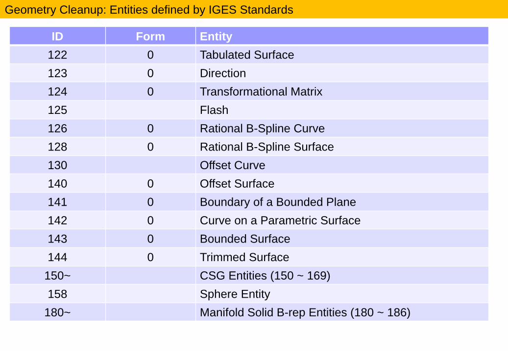
ID Form Entity
122 0 Tabulated Surface
123 0 Direction
124 0 Transformational Matrix
125 Flash
126 0 Rational B-Spline Curve
128 0 Rational B-Spline Surface
130 Offset Curve
140 0 Offset Surface
141 0 Boundary of a Bounded Plane
142 0 Curve on a Parametric Surface
143 0 Bounded Surface
144 0 Trimmed Surface
150~ CSG Entities (150 ~ 169)
158 Sphere Entity
180~ Manifold Solid B-rep Entities (180 ~ 186)
Geometry Cleanup: Entities defined by IGES Standards

ID Form Entity
190 Plane Surface Entity
192 Right Circular Cylindrical Surface Entity
194 Right Circular Conical Surface Entity
196 Spherical Surface Entity
198 Toroidal Surface Entity
304 Line Font Definition
406 Name Associated with an Entity or Group of Entity
408 Singular Subfigure Instance
504 Edge Entity
508 Loop Entity
510 Face Entity
514 Shell Entity
Geometry Cleanup: Entities defined by IGES Standards