georgetown wet weather treatment station contract no
TRANSCRIPT

Department of Natural Resources and Parks Wastewater Treatment Division
Executed Counterparts Counterpart No. _______ of _______
Including Addenda Nos. _______ through _______
CPA No. ______________
Georgetown Wet Weather Treatment Station - Outfall
Contract No. C01072C17
Funded in part by the Washington State Department of Ecology
Volume 2 of 5
Technical Specifications
September 2017

This page intentionally left blank.
GEORGETOWN WET WEATHER TREATMENT STATION
OUTFALL
Contract No. C01072C17
TECHNICAL SPECIFICATIONS
August 2017
Prepared by:
William P. Fox Cosmopolitan Marine Engineering
(253) 265-2958
Ade J. Bright Bright Engineering
(206) 625-3777
01010, 01012, 01014, 01025, 01035, 01050, 01062, 01063, 01065, 01195, 01200, 01300, 01310, 01350, 01380, 01410, 01420, 01430, 01500, 01560, 01561, 01570, 01710, 01715, 01720, 01730, 01740, 01999, 02045, 02110, 02323, 02271, 02272, 02618, 02628, 11009,
13110, 15112
02161, 03200, 03301, 03401, 05500, 05520, 08310, 11120

Karen Dawson CH2M
(425) 453-5000
Raymond W. Chung CH2M
(425) 453-5000
01036, 02050, 02060, 02121, 02140, 02200 02720, 02726
Jonathan Morley Berger Partnership
(206) 325-6877
02900, 02920
I herby certify that the Project Plans and Specifications were prepared by me or under my direct supervision and I am duly registered Engineer under the laws of the State of Washington.

TABLE OF CONTENTS GEORGETOWN WET WEATHER TREATMENT STATION - OUTFALL
CONTRACT C01072C17
C01072C17 page 1 of 2 Table of Contents Rev. 6/14/2017
VOLUME 1 OF 5 DIVISION 00 – BIDDING REQUIREMENTS, FORMS AND TERMS AND CONDITIONS
00020 00100 00120
00130 00300 00310 00410 00420 00430 00440 00500 00600 00700 00800 00900
Invitation to Bid Instructions to Bidders Non-Discrimination, Equal Employment Opportunity, Minority and Women Business Enterprises Utilization, and Apprenticeship Requirements Wage Rates Form of Bid Bid Guaranty Bond Forms and Documents Due Prior to Contract Execution Performance and Payment Bond Insurance Requirements Qualification Information Agreement Addenda General Terms and Conditions Supplemental Terms and Conditions Escrow Bid Documentation
VOLUME 2 OF 5 DIVISION 01 – GENERAL REQUIREMENTS
01010 Summary of Work 01012 Reference Material 01014 Milestones and Constraints 01025 Measurement and Payment 01035 Asbestos and Lead Information 01036 Geotechnical Information 01050 Survey Information 01062 Permits and Easements 01063 Health and Safety 01065 Sewer Access 01195 Protection and Maintenance of Property and Work 01200 Contract Meetings 01300 Submittals Procedure 01310 Project Schedules and Reports 01350 Sustainability Requirements 01380 Photographs and Videos 01410 Construction Testing and Inspection 01420 Special Inspection, Observation, and Testing 01430 Quality Control Program 01500 Contractor's Construction Facilities 01560 Environmental Management 01561 Environmental Controls for Marine Construction 01570 Traffic Regulation 01710 Final Cleaning 01715 Construction Waste Management 01720 Record Drawings 01725 Asset Data 01730 Operation and Maintenance Information and Manuals

TABLE OF CONTENTS (CONT.)
C01072C17 page 2 of 2 Table of Contents Rev. 6/14/2017
01740 Guaranty and Warranty 01999 Standard Forms
DIVISION 02 – SITE WORK 02045 Cutting and Patching 02050 Demolition and Disposal 02060 Contaminated Soil and Sediment Handling and Disposal 02110 Site Clearing and Grubbing 02121 Deformation and Vibration Monitoring 02140 Dewatering 02161 Excavation Support and Work Bridge Systems 02200 Earthwork 02270 Erosion and Sediment Control 02271 Site Water Discharge 02272 Temporary Stormwater Bypass 02323 Excavation and Backfill for Marine Outfall 02618 Steel Pipe 02628 High-Density Polyethylene Outfall Pipe 02720 Storm Drainage System 02726 Stormwater Treatment System 02910 Landscaping and Habitat Restoration 02920 Landscape Soil Materials
DIVISION 03 – CONCRETE 03200 Concrete Reinforcement 03301 Cast-in-Place Concrete Small Jobs 03401 Precast Concrete Anchor Blocks and Accessories
DIVISION 05 – METAL 05500 Metal Fabrications 05520 Metal Handrailing
DIVISION 08 – DOORS AND WINDOWS 08310 Access Hatches
DIVISION 11 – EQUIPMENT 11009 Equipment List 11120 Flap Gates
DIVISION 13 – SPECIAL CONSTRUCTION 13110 Cathodic Protection System
DIVISION 15 – MECHANICAL 15112 Duckbill Diffuser Check Valves
VOLUME 3 OF 5 – CONTRACT DRAWINGS
VOLUME 4 OF 5 – GEOTECHNICAL DATA REPORT
VOLUME 5 OF 5 – PERMITS AND EASEMENTS, BIOLOGICAL ASSESSMENT AND ESSENTIAL FISH HABITAT ASSESSMENT,AND MITIGATION AND MONITORING PLAN

DIVISION 01 GENERAL REQUIREMENTS

This page left intentionally blank.

August 2017 C01072C17 Georgetown Wet Weather Treatment Station 01010 - 1 SUMMARY OF WORK
SECTION 01010
SUMMARY OF WORK
PART 1 GENERAL
1.01 SUMMARY
A. This Section summarizes the work in this Contract and other known work in the vicinity of the Contract work.
B. The work to be performed under this Contract consists of furnishing all tools, equipment, materials, supplies, and manufactured articles; furnishing labor, transportation, and services, including fuel, power, water, and essential communications; and performing work or other operations required for the fulfillment of the Contract in strict accordance with the Contract Documents. Provide work complete. Provide work, materials, and services not expressly indicated in the Contract Documents that may be necessary for the complete and proper construction of the work and administration of the Contract.
C. The project work is located in the City of Seattle near the SR 99/509 Bridge (also known as First Avenue South Bridge) over the Duwamish Waterway. This project is part of King County’s Georgetown Wet Weather Treatment Station project, which will reduce the discharge of untreated combined sewer overflows to the Lower Duwamish Waterway during wet weather.
1.02 QUALITY ASSURANCE (NOT USED)
1.03 SUBMITTALS (NOT USED)
1.04 WORK OF THIS CONTRACT
A. The work of this Contract includes: 1. Outfall:
a. Approximately 306 lineal feet of 54-inch-outside-diameter high density polyethylene (HDPE) outfall pipe into the Lower Duwamish Waterway (LDW). 1) Approximately 106 lineal feet constructed within a shored trench. 2) Approximately 200 lineal feet constructed with shallow burial or laid on existing grade.
b. Last 50 feet of outfall to include eight 20-inch elastomeric duckbill valves for diffusion of effluent to the LDW.
c. Precast concrete anchors bolted onto the pipe to provide weight and stability to the pipe. d. Removal and disposal of steel and creosote pilings and other debris on the shoreline. e. Post-construction restoration of the shoreline armoring. f. Post-construction restoration of an existing upper-intertidal swale, including plantings.
2. Effluent Conveyance: a. Approximately 19 lineal feet of 60-inch-inside-diameter lined and coated steel effluent
conveyance pipe. 3. Drop Structure:
a. Cast-in-place concrete structure within a shored and dewatered excavation. b. Pipe spools cast into structure walls for connection to effluent conveyance and outfall pipes. c. Flap gate check valve on entrance to drop structure. d. Miscellaneous appurtenances.
4. And other work as defined in the Contract Documents.
B. The above description is not intended to be complete. The work to be completed is provided for in the Contract Documents. The summary in this Section is not intended to relieve the Contractor of the responsibility for reading and understanding the Contract Documents.

August 2017 C01072C17 Georgetown Wet Weather Treatment Station 01010 - 2 SUMMARY OF WORK
C. Federal, State and Local Laws, Statutes and Regulations are not individually referenced. This provision incorporates by reference the latest version of statutes, laws and regulations. In case of conflict between the requirements of the specifications and requirements of the statutes and regulations, the Contractor shall bring them to the attention of the Project Representative. Lacking a specific response, the more stringent shall control. In no case can this Contract be interpreted to override statutes and regulations of governing authorities.
D. National and industry codes cited, such as IBC, NEC, NFPA, shall include amendments and supplements by the local authority having jurisdiction whether stated or not.
1.05 WORK UNDER OTHER COUNTY CONTRACTS OR BY COUNTY STAFF
A. Onshore end of this construction contract will connect to an onshore effluent conveyance pipeline that will be constructed during the work of this Contract under Georgetown Wet Weather Treatment Station Conveyance Contract No. C01071C17.
1.06 OTHER RELATED CONTRACTS (NOT USED)
1.07 SPECIFICATION LANGUAGE
A. Specifications are written mostly in imperative and streamlined form. Unless indicated otherwise, this imperative language is directed to the Contractor. Additionally, the words "shall be" shall be included by inference where a colon (:) is used within sentences or phrases. 1. Examples:
a. Aggregate: ASTM C33. b. Adhesive: spread with notched trowel.
B. Whenever there is wording stating that an item is “as specified”, “as shown”, or “as indicated”, the reference is to the Contract Documents. Stating “as specified”, “as shown”, or “as indicated” does not refer necessarily to a Drawing or Specification, but it refers to either.
C. The words “Provide” and “Furnish” shall mean supplying, installing, and incorporating into the work including all labor, materials, supplies and equipment necessary to do so. The word “Supply” shall mean to acquire, deliver and transfer the item to the County as specified.
D. Unless otherwise indicated, materials and equipment incorporated into the work shall be as specified and shall be new and free of defects.
1.08 DEFINITIONS
A. Drawing: means a Drawing that is an element of the Contract Documents.
B. Acceptable Manufacturers: Manufacturers that may produce material or equipment that meet the requirements of the Contract Documents.
1.09 REFERENCED SPECIFICATION
A. Whenever a Specification in this Contract references the specifications of WSDOT or Local Jurisdiction, it is to define the technical standards to be met for this Contract; only the technical standards are referenced. Administrative provisions such as Measurement and Payment of the referenced specification shall not apply to this Contract in any instance.
B. Whenever a Specification in this Contract references the specifications of the City of Seattle, the term Engineer shall mean the Project Representative.

August 2017 C01072C17 Georgetown Wet Weather Treatment Station 01010 - 3 SUMMARY OF WORK
1.10 PERMITS AND EASEMENTS
A. Work will be conducted within and along the shoreline of the LDW, and is subject to the constraints of permits and easements that are included in the Contract Documents. Comply with all permit and easement requirements.
PART 2 PRODUCTS (NOT USED)
PART 3 EXECUTION (NOT USED)
END OF SECTION

August 2017 C01072C17 Georgetown Wet Weather Treatment Station 01010 - 4 SUMMARY OF WORK
This page intentionally left blank.

August 2017 C01072C17 Georgetown Wet Weather Treatment Station 01012 - 1 REFERENCE MATERIAL
SECTION 01012
REFERENCE MATERIAL
PART 1 GENERAL
1.01 SUMMARY
A. The documents are available on the Procurement Website for this project at http://www.kingcounty.gov/procurement/.
B. Reference documents are provided for informational purposes only and are not to be considered Contract Documents.
C. For the Work related to the Contract, the following are considered reference documents: 1. “King County First Avenue Bridge Conditions Survey Report” dated May 18, 2015 by Global
Diving and Salvage, Inc. and Terrasond. 2. Technical Memorandum titled, “Underwater Reconnaissance in Duwamish Waterway” by Bill
Fox/Cosmopolitan Marine Engineering dated July 8, 2015. 3. Georgetown Current Meter Analysis February 9, 2016 – March 16, 2016, dated August 2017
prepared by King County. 4. The Consent Decree in the case entitled United States of America and the Station of Washington
v. King County (USDC Civil Action No. 2:13-cv-677 lodged on April 16, 2013).
D. The Work in this Contract shall be conducted within WSDOT right-of-way and adjacent to their southbound SR 99/509 (First Avenue South) bridge structures. Record drawings for the bridge are not provided for in these Contract Documents for the bid period. The successful Contractor awarded this Contract shall contact WSDOT and enter into an agreement to obtain SR 99/509 record drawings.
1.02 QUALITY ASSURANCE (NOT USED)
1.03 SUBMITTALS (NOT USED)
PART 2 PRODUCTS (NOT USED)
PART 3 EXECUTION (NOT USED)
END OF SECTION

August 2017 C01072C17 Georgetown Wet Weather Treatment Station 01012 - 2 REFERENCE MATERIAL
This page intentionally left blank.

August 2017 C01072C17 Georgetown Wet Weather Treatment Station 01014 - 1 MILESTONES AND CONSTRAINTS
SECTION 01014
MILESTONES AND CONSTRAINTS
PART 1 GENERAL
1.01 SUMMARY
A. This Section specifies completion times, milestones, constraints, hours of work, and liquidated damages.
B. Schedule and conduct work in a manner consistent with the Contract, and comply with the construction scheduling requirements, Contract milestones, and constraints on the work in its entirety.
1.02 QUALITY ASSURANCE (NOT USED)
1.03 SUBMITTALS
A. Submit a schedule of working hours in accordance with Section 00700, this Section, and Section 01062. 1. Incorporate all milestones and constraints into the working hour schedule per Section 01310.
1.04 DEFINITIONS
A. Wet Season: October 1 to April 30.
B. Dry Season: May 1 to September 30.
C. Dry Weather: A period when no measurable rainfall is occurring, no rainfall occurred in the previous 48 hours, and no rainfall is forecasted by the National Weather Service for Seattle for the scheduled length of the task activities plus one day.
D. Wet Weather: A period when measurable rainfall is occurring or where sewer flow rates are higher due to rainfall that has occurred.
E. Construction Completion: This term in this Contract does not mean Substantial Completion. Substantial Completion has separate and distinct requirements as stated elsewhere in this Contract. Construction Completion shall mean all construction and installation of equipment or infrastructure required to achieve CSO Control Measures as required by the reference document entitled Consent Decree, in the case of United Stated of America and the State of Washington v. King County (USDC Civil Action No. 2:13-cv- 677JCC), lodged with the court on April 16, 2013 such that equipment or infrastructure has been placed in operation, and is expected to both function and perform in compliance with the Contract Specifications. Construction Completion includes, but is not limited to, furnishing, testing and commissioning of all control systems and instrumentation necessary for normal operations and all residual handling systems, and the provision of complete operations and maintenance manuals.
1.05 COMPLETION TIMES
A. Substantial Completion: 425 days after the effective date of Notice to Proceed.
B. Construction Completion: Not later than December 31, 2022, as required by the Consent Decree.
C. Achieve Final Acceptance within the time specified by the Project Representative and stated in the Certificate of Substantial Completion per Section 00700.

August 2017 C01072C17 Georgetown Wet Weather Treatment Station 01014 - 2 MILESTONES AND CONSTRAINTS
1.06 MILESTONES
A. Milestone 1: Construction Completion December 31, 2022, which is expected to occur several years after Substantial Completion.
1.07 CONSTRAINTS
A. Concurrent closure of traffic lanes on South River Street and traffic lanes on South Michigan Street west of East Marginal Way South is not allowed.
B. No construction work or equipment staging may be conducted below the mean lower low tide elevation for the period October 1 through November 25, except for placement of silt curtains and movement of small work skiffs, or as approved by the Project Representative.
C. In-water construction work below mean higher high water tide elevation and above mean lower low tide elevation may be conducted between October 1 and November 25.
D. All in-water construction work at any elevation must be completed pursuant to the above constraints and within one work window period beginning October 1 through the following February 15.
1.08 HOURS OF WORK
A. Unless otherwise specified, conform to applicable jurisdictions and other pertinent ordinances regarding limitations on work hours or specific parts of the work. Various permits issued for this project (including those in Section 01062), specify work during low tides only for certain activities, which may require night work. Request work hour variations in writing and obtain written approval from Local Authority Having Jurisdiction (including the City of Seattle as applicable) and the Project Representative prior to initiating work hours outside of the hours noted in all permits, including those referenced in Section 01062 of the Contract.
B. Contractor shall comply with hours of work and related restrictions as modified by permits, including those referenced in Section 01062.
C. Work outside of the scheduled work hours shall be submitted in writing, and requires approval by the Project Representative three days prior to the start of such work. 1. If the Contractor works unscheduled hours, or if the Contractor has not obtained Project
Representative's approval at least three days prior to the start of unscheduled work, the Contractor shall be liable for the costs of King County's and their representatives overtime inspection, including the following agencies. The rates will change on a yearly basis. The Contractor shall provide compensation at the overtime rates applicable at the time of the work. Payment will be withheld from payment applications. a. King County: 2019 rate of $107 for each hour for each person performing such inspection for
King County. b. City of Seattle: 2019 rate of $107 for each hour for each person performing such inspection
for City of Seattle. c. Washington Department of Transportation: 2019 rate of $107 for each person performing
such inspection for Washington Department of Transportation.
1.09 LIQUIDATED DAMAGES
A. Liquidated damages for failure to achieve Substantial Completion, shall be in the amount of $2,400.00 per day.
B. Liquidated damages for failure to achieve Final Acceptance, shall be in the amount of $240.00 per day.

August 2017 C01072C17 Georgetown Wet Weather Treatment Station 01014 - 3 MILESTONES AND CONSTRAINTS
1.10 OTHER DAMAGES
A. Damages shall be assessed, as follows, for failure to achieve Milestone 1, Construction Completion, by the following dates.
Date Consent Decree Penalty January 1, 2023 to January 14, 2023 $3,000 per day January 15, 2023 to January 30, 2023 $4,000 per day Each day after January 30, 2023 $5,000 per day
1. The dates indicated above are firm dates that are prescribed by Section 11(d) of the reference document entitled Consent Decree, in the case of United Stated of America and the State of Washington v. King County (USDC Civil Action No. 2:13-cv- 677JCC), lodged with the court on April 16, 2013. The dates will not be modified by the County for Change Orders in Contract Time or Contract Price related to this Contract. However, if a force majeure event occurs under §00700 Paragraph 5.5 of the contract and if the County, in its sole discretion, elects to request an extension of a date from the United Stated Environmental Protection Agency and the Washington State Department of Ecology, and if such extension request is granted, then the County may issue a Change Order that modifies one or more dates in Paragraph 01014-1.10.E. Nothing in the subparagraph shall be construed as creating a duty on the County’s part to request an extension upon the occurrence of a force majeure event or issue a Change Order if such an extension is granted.
B. As stated in this Section 01014 in-water work must be completed in one work window October 1, 2018 through February 15, 2019. If the in-water work is not completed with that constraint, another in-water work window must be negotiated with the Suquamish and Muckleshoot Tribes and regulatory agencies by the Contractor. The Contractor will be responsible for all the costs related to the additional in-water work window.
PART 2 PRODUCTS (NOT USED)
PART 3 EXECUTION (NOT USED)
END OF SECTION

August 2017 C01072C17 Georgetown Wet Weather Treatment Station 01014 - 4 MILESTONES AND CONSTRAINTS
This page intentionally left blank.

August 2017 C01072C17 Georgetown Wet Weather Treatment Station 01025 - 1 MEASUREMENT AND PAYMENT
SECTION 01025
MEASUREMENT AND PAYMENT
PART 1 GENERAL
1.01 SUMMARY
A. Measurement is described under each bid item in this Section.
B. Payment for the various items on the Bidding Schedule, as further specified herein, shall include compensation to be received by the Contractor for furnishing tools, equipment, supplies, and manufactured articles, and for labor, operations, and incidentals appurtenant to the items of work being described, as necessary to complete the various items of the work all in accordance with the requirements of the Contract Documents, including appurtenances thereto and including costs of compliance with the regulations of public agencies having jurisdiction, including safety and health requirements of the Occupational Safety and Health Administration of the U. S. Department of Labor (OSHA). No separate payment will be made for any item that is not specifically set forth in the Bidding Schedule, and all costs therefore shall be included in the prices named in the Bidding Schedule for the various appurtenant items of work.
C. Payment for the Work of this Contract is defined below. No other document, referenced or otherwise, shall be considered for payment.
D. Payment for Lump Sum bid items shall be based on the Schedule of Values percentage of completion method for each Schedule of Values line item. Schedule of Values shall include payment constraints listed elsewhere in the Contract specifications.
1.02 QUALITY ASSURANCE (NOT USED)
1.03 SUBMITTALS (NOT USED)
1.04 BID ITEM MEASUREMENT AND PAYMENT
A. The Bidding Schedule is divided into the bid items whose definitions follow. Bid Item Nos. 1 through 4 represent the entire scope of work covered by the Contract Documents.
B. Bid Item No. 1 – Outfall Drop Structure—(Lump Sum): 1. This bid item shall include all work indicated in the Contract Documents for construction of the
cast-in-place drop structure and appurtenances, including 60-inch-diameter steel pipe. 2. Measurement shall be in accordance with a reasonable apportionment of the work as established
in the Schedule of Values. 3. Payment will be based upon the percentage of completion for each appropriate line item in the
Schedule of Values.
C. Bid Item No. 2 – Outfall Pipeline—(Lump Sum): 1. This bid item shall include all work indicated in the Contract Documents, except that included in
Bid Items No. 1, 3, and 4. 2. Measurement shall be in accordance with a reasonable apportionment of the work as established
in the Schedule of Values. 3. Payment will be based upon the percentage of completion for each appropriate line item in the
Schedule of Values.

August 2017 C01072C17 Georgetown Wet Weather Treatment Station 01025 - 2 MEASUREMENT AND PAYMENT
D. Bid Item No. 3: Trench Safety Systems—(Lump Sum): 1. This bid item is for all work necessary for Trench Excavation Safety Systems in performing work
under this Contract, for the installation and use of Excavation Support System, Class A, to meet the requirements of RCW 39.04.180 and Chapter 49.17 RCW, in accordance with WAC 296-155-650.
2. Measurement shall be in accordance with a reasonable apportionment of the work as established in the Schedule of Values.
3. Payment will be based upon the percentage of completion for each appropriate line item in the Schedule of Values.
E. Bid Item No. 4: Stormwater Treatment System—(Lump Sum): 1. This bid item shall include all work indicated in the Contract Documents for construction of the
underground structural Stormwater Treatment System. 2. Measurement shall be in accordance with a reasonable apportionment of the work as established
in the Schedule of Values. 3. Payment will be based upon the percentage of completion for each appropriate line item in the
Schedule of Values.
PART 2 PRODUCTS (NOT USED)
PART 3 EXECUTION (NOT USED)
END OF SECTION

August 2017 C01072C17 Georgetown Wet Weather Treatment Station 01035 - 1 ASBESTOS AND LEAD INFORMATION
SECTION 01035
ASBESTOS AND LEAD INFORMATION
PART 1 GENERAL
1.01 SUMMARY
A. This Section provides information pursuant to 29 CFR 1926.1101, WAC 296-62-077, Chapter 296-65 WAC, WAC 296-155-176 and to all other applicable requirements concerning working on, working around, and reporting on asbestos and lead containing materials including suspect material encountered during construction.
B. The information in this Section is based on the results of a good faith review of the Contract Work requirements and a site inspection of the proposed work areas to determine the presence of asbestos or lead containing materials. This review and inspection were performed by King County's AHERA Certified Building Inspector in strict accordance with 29 CFR 1926, WAC 296-62-077, Chapter 296-65 WAC, WAC 296-155-176, and with the accepted principles and protocol mandated by AHERA.
C. Demolition activities identified on the Drawings and Section 02050 include removal of river bank armouring materials, removal of a sunken dock and removal of creosote-treated timber piles. No sampling investigation reports are provided for this Section of any piping, painted surfaces, building and structural materials as they are not yet accessible. TLead or asbestos may also be found in soils, vegetation or other environments encountered during this construction. This Section provides information on reporting of suspect material encountered during construction to the Project Representative for further assessment.
D. Notify all employees and subcontractors who are on site or perform work subject to this Section of the contents of this Section.
1.02 QUALITY ASSURANCE
A. Referenced Standards: This Section incorporates by reference the latest revisions of the following documents. These references are a part of this Section as specified and modified. In case of conflict between the requirements of this Section and those of the listed documents, the requirements of this Section shall prevail. Reference Title AHERA (Federal) Asbestos Hazard Emergency Response Act 29 CFR 1926.1101 Safety and Health Regulations for Construction: Asbestos WAC 296-62-077 Occupational Health Standards: Asbestos, Tremolite, Anthrophyllite and
Actinolite Chapter 296-65 WAC WISHA Asbestos Standards WAC 296-155-176 Safety Standards for Construction Work - Lead
1.03 SUBMITTALS
A. Abatement and Disposal Plan – if suspect material is encountered and confirmed by Project Representative to require handling under this Section by the Contractor.
1.04 ASBESTOS INSPECTION
A. The County's Inspection has determined to the best of its ability that the proposed construction areas under this Contract and the materials therein, do not contain asbestos.

August 2017 C01072C17 Georgetown Wet Weather Treatment Station 01035 - 2 ASBESTOS AND LEAD INFORMATION
1.05 LEAD INSPECTION
A. The County's Inspection has determined to the best of its ability that the proposed construction areas, under this Contract and the materials therein, do not contain lead.
1.06 CONTRACTOR'S RESPONSIBILITIES
A. Should suspect material not identified in this Section be encountered, immediately suspend all work that could disturb said material and notify the Project Representative who will implement the proper action. Notification to the Project Representative will be by voice and in writing. Do not proceed with work that could disturb the material until authorized by the Project Representative, in writing, to do so.
B. Take the necessary precautions for compliance with Local, State and Federal regulations.
C. When regulated substances are present, submit an Abatement and Disposal Plan.
D. Comply with Section 01063.
E. Fully inform workers of the presence of hazardous materials.
1.07 COUNTY'S RESPONSIBILITIES
A. Upon notification by the Contractor of the existence of suspect material not identified in this Section, the Project Representative will have said material inspected and analyzed for the presence of asbestos or lead, as required.
B. If the results of the inspection and analysis confirm the presence of asbestos in the suspect material, the County will take the necessary actions for compliance with 29 CFR 1926.1101 and WAC 296-62-077. After compliance is obtained, the Project Representative will notify the Contractor in writing so that work suspended can proceed.
C. If the results of the inspection and analysis confirm the presence of lead in the suspect material, the County will take the necessary actions for compliance with WAC 296-155-176. After compliance is obtained, the Project Representative will notify the Contractor in writing so that work under this Contract can proceed.
D. If the results of the inspection and analysis confirm the presence of other dangerous, hazardous or regulated substances in the suspect material, the County will take the necessary actions for compliance with State and Federal regulations. After compliance is obtained, the Project Representative will notify the Contractor in writing so that work under this Contract can proceed.
E. If the results of the inspection and analysis confirm that the suspect material is free of asbestos, lead, or other regulated substances, the Project Representative will notify the Contractor in writing so that work suspended can proceed.
PART 2 PRODUCTS (NOT USED)
PART 3 EXECUTION
3.01 HEALTH AND SAFETY
A. Comply with Section 01063.
END OF SECTION

August 2017 C01072C17 Georgetown Wet Weather Treatment Station 01035 - 3 ASBESTOS AND LEAD INFORMATION
Wastewater Treatment Division KSC-NR-0509 201 S. Jackson St. Seattle, WA. 98104-3855 August 3, 2017 TO: Will Sroufe FROM: Darrell Myers
Project Planning and Delivery Section
SUBJECT: Georgetown Wet Weather Treatment Station
This project has been reviewed by Darrell Myers, AHERA Building Inspector Certificate #160720, (expires January 18, 2018). A good faith review of the drawings and site visit indicate no asbestos or lead in the area of work.

August 2017 C01072C17 Georgetown Wet Weather Treatment Station 01035 - 4 ASBESTOS AND LEAD INFORMATION
This page intentionally left blank.

August 2017 C01072C17 Georgetown Wet Weather Treatment Station 01036 - 1 GEOTECHNICAL INFORMATION
SECTION 01036
GEOTECHNICAL INFORMATION
PART 1 GENERAL
1.01 SUMMARY
A. This Section specifies geotechnical information for the Contract.
1.02 QUALITY ASSURANCE (NOT USED)
1.03 SUBMITTALS (NOT USED)
1.04 GEOTECHNICAL DOCUMENTS
A. The following geotechnical documents are considered part of the Contract to provide geotechnical information, included in Volume 4 of this contract: 1. Georgetown Wet Weather Treatment, Geotechnical Data Report, Revision 1. Dated May 1,
2017. Prepared by: CH2M, 1100 112th Ave NE, Suite 500, Bellevue, WA 98004. a. Presents the results of the field investigation program and geotechnical laboratory testing
performed and gathered for all the GWWTS projects. b. Includes exploration locations, boring logs, cone penetrometer test results, test pit logs,
laboratory test results, findings of underwater probing and diver reconnaissance and groundwater levels.
2. King County. 2017. Project 423530, GWWTS Soil Cores Samples L66600-1 to -3, Collected Nov. 18 and Dec 20, 2016. King County Water and Land Resources Division Environmental Lab Analytical Report. January 24. 62 pp.
3. Pacific Rim Laboratories, Inc., 2017. PR164136, Data Report, prepared for King County. January. 191 pp.
1.05 GEOTECHNICAL INFORMATION USE
A. The contractor shall make own interpretations, evaluations and conclusions as to the nature of the geotechnical materials and conditions to determine the difficulties performing the Work affected by the geotechnical conditions.
B. In making interpretations, evaluations, and conclusions, use the Contract geotechnical documents and the available geotechnical information in a manner that includes a reasonable interpretation after consulting with a Professional Civil Engineer with geotechnical expertise or a Geologist with applicable expertise licensed in the state of Washington.
C. The contractor may also conduct other investigations and tests deemed appropriate. Any additional investigation and test information shall be shared with the County.
D. The contractor shall accept full responsibility for making interpretations and conclusions that differ from the baselines set in the geotechnical documents.
PART 2 PRODUCTS (NOT USED)
PART 3 EXECUTION (NOT USED)
END OF SECTION

August 2017 C01072C17 Georgetown Wet Weather Treatment Station 01036 - 2 GEOTECHNICAL INFORMATION
This page intentionally left blank.

August 2017 C01072C17 Georgetown Wet Weather Treatment Station 01050 - 1 SURVEY INFORMATION
SECTION 01050
SURVEY INFORMATION
PART 1 GENERAL
1.01 SUMMARY
A. This Section specifies survey work requirements.
1.02 QUALITY ASSURANCE
A. Reference Standards: This Section incorporates by reference the latest revision of the following documents. These references are a part of this Section as specified and modified. In case of conflict between the requirements of this Section and those of the listed documents, the requirements of this Section shall prevail. Reference Title RCW 58.24.040 Revised Code of Washington Official Agency Designated – Powers
Standards, Maps
B. Qualifications: 1. Surveyor: Professional Land Surveyor registered in the state of Washington.
1.03 SUBMITTALS
A. Procedures: Section 01300.
B. Qualifications of the surveyor.
C. Cut sheets for pavement restoration work.
D. Survey field notes and survey calculations.
E. Record drawings for pipelines, facilities, and structures stamped, signed, and dated by Surveyor.
F. Control point(s) for vertical and horizontal control are indicated in the Drawings. Verify and use Contract control points as basis of work.
G. Complete pre-construction survey of swale.
H. Pre-construction survey of waterway bottom.
1.04 SURVEY BY CONTRACTOR
A. Using the verified Contract control point(s), develop and make additional surveys as needed for construction, such as control lines, slope stakes, settlement markers, batter boards, stakes for pipe locations, and other working points, lines, and elevations. Re-establish any benchmarks and survey control points destroyed.
B. Complete the layout for the work and be responsible for measurements that may be required for the execution of the work to the location and limits indicated in the Drawings.

August 2017 C01072C17 Georgetown Wet Weather Treatment Station 01050 - 2 SURVEY INFORMATION
C. Perform survey monument referencing for tie-out prior to the work in the right-of-way and prior to pavement restoration. Check and restore monuments and their casings at completion of work.
D. Maintain and preserve stakes and other marks established until authorized by the Project Representative to remove them.
E. Project Representative may require that work be suspended at any time when location and limit marks established by the Contractor are not reasonably adequate to permit inspection of the work.
F. In advance of the pavement restoration (including pavement, curb, and gutter), produce survey information to check the line and grade which the Contractor will use for elevations and slopes.
G. Complete pre- and post-construction survey of swale within construction limits that are affected by construction.
H. Complete pre- and post-construction multi-beam acoustic survey of waterway bottom below mean lower low water, along 50-foot-wide corridor centered on the outfall alignment.
I. Comply with the survey requirements for monitoring as specified in other Sections.
J. Provide new replacement monuments and boxes when removed or damaged during construction and file an application for permit to remove or destroy a survey monument with the Washington State Department of Natural Resources, pursuant to RCW 58.24.040(8).
K. Re-establish permanent survey control monuments prior to Substantial Completion.
L. Provide line and grade of the pipelines, facilities, and structures to be installed per the Contract Documents.
M. Provide requirements of the record drawings per Section 01720.
PART 2 PRODUCTS (NOT USED)
PART 3 EXECUTION
3.01 GENERAL
A. Perform surveys based on control points as indicated in the Drawings and verified by the Surveyor. Use surveys to establish base lines, line and grade hubs, stake elevations, and other reference and construction points.
B. Replaced monuments shall be set by the Surveyor.
C. Offset reference stakes: 1. Set at 25-foot intervals for pipelines. 2. Set at 50-foot intervals on tangents and 25-foot intervals on curves. 3. Set additional points as required by the Project Representative.
D. In advance of pavement restoration (including pavement, curb, and gutter), produce survey information required to establish elevations, slopes, and cross sections.

August 2017 C01072C17 Georgetown Wet Weather Treatment Station 01050 - 3 SURVEY INFORMATION
3.02 FIELD NOTES
A. Keep in standard bound survey field notebooks using a clear, orderly manner consistent with standard surveying practice. Include titles, numbering, and indexing.
B. Keep a copy of field notes including references to monuments and property corners. Submit if required by the Project Representative.
C. Keep a copy of grade sheets completed prior to all permanent pavement restoration.
END OF SECTION

August 2017 C01072C17 Georgetown Wet Weather Treatment Station 01050 - 4 SURVEY INFORMATION
This page intentionally left blank.

August 2017 C01072C17 Georgetown Wet Weather Treatment Station 01062 - 1 PERMITS AND EASEMENTS
SECTION 01062
PERMITS AND EASEMENTS
PART 1 GENERAL
1.01 SUMMARY
A. This Section specifies permit and easement acquisition, private access agreements, and related requirements and conditions.
B. Copies of County-obtained permits, easements, and private access agreements are located in Volume 5.
1.02 QUALITY ASSURANCE (NOT USED)
1.03 SUBMITTALS
A. Procedures: Section 01300.
B. Written notifications indicating proposed access dates to private properties.
C. Permits, private access agreements, and easements obtained by the Contractor.
D. ‘Permit Complete’ approvals when work is complete and accepted by the Local Authority Having Jurisdiction (LAHJ), whether permits were obtained by the Contractor or the County. Include records of permit documentation and testing results during construction.
E. Construction Restoration Acceptance Forms (Form 01062-A, included in Section 01999).
F. Easement Tracking Table; submit monthly.
G. Private Property Restoration Plan for each private property.
H. Pre- and post-construction photographs as required in the Hydraulic Project Approval.
1.04 PERMITS
A. The County has acquired the following permits/approvals from the Local Authority Having Jurisdiction [LAHJ]: 1. U.S. Army Corps of Engineers (USACE) – Section 10/404 Nationwide Permit 7. 2. U.S. Army Corps of Engineers – Section 408 Authorization. 3. U.S. Fish and Wildlife – Concurrence Letter. 4. National Marine Fisheries Service – Biological Opinion. 5. WA Department of Ecology – Section 401 Water Quality Certification (approved through the
USACE Permit). 6. WA Department of Ecology – Coastal Zone Management Act Consistency Certification (approved
through the USACE Permit). 7. WA Department of Ecology – NPDES Construction Stormwater General Permit. 8. WA Department of Ecology – Shoreline Conditional Use Permit Approval. 9. WA Department of Archaeology and Historic Preservation – National Historic Preservation Act,
Section 106 consultation. 10. WA Department of Fish and Wildlife – Hydraulic Project Approval. 11. Seattle Department of Construction and Inspections – MUP Use Permit II - SEPA Conditioning.

August 2017 C01072C17 Georgetown Wet Weather Treatment Station 01062 - 2 PERMITS AND EASEMENTS
12. Seattle Department of Construction and Inspections – Land Use Permit – Shoreline Conditional Use, Shoreline Development, and SEPA Conditioning
13. Seattle Department of Transportation – Haul Route Approval. 14. King County Industrial Waste – Wastewater Discharge Authorization. 15. King County Wastewater Treatment Division – State Environmental Policy Act (SEPA)
Determination of Nonsignificance. 16. Agreement between The Suquamish Tribe and King County, Georgetown Wet Weather
Treatment Station Project in the Duwamish River, dated May 25, 2017. 17. Agreement between Muckleshoot Indian Tribe and King County, Georgetown Wet Weather
Treatment Station Project in the Duwamish River, dated May 5, 2017.
B. The following documents are referenced in the U.S. Army Corps of Engineers’ Nationwide Permit 7 and/or WA Department of Fish and Wildlife Hydraulic Project Approval, and are included in these Contract Documents. 1. “Biological Assessment and Essential Fish Habitat Assessment,” prepared by ESA dated
December 2015 included as Attachment C in Volume 5. 2. “Mitigation and Monitoring Plan,” Final Report prepared by Environmental Science Associates
dated March 2016 included as Attachment D in Volume 5.
C. Copies of the permits obtained by the County, and documents listed in Section B above, are included in Attachment A of Volume 5. Unless otherwise indicated, comply with and be responsible for all terms and conditions and permit requirements contained in such permits.
D. The following lists permit conditions which are not the responsibility of the Contractor: 1. Any necessary extension of permit deadline will be applied for (and permit fees paid) by the
County. Notify the Project Representative a minimum of 30 days prior to an extension being necessary.
1.05 EASEMENTS AND ACCESS AGREEMENTS
A. The County has acquired the following easements and private access agreements:
Parcel Number(s) Property Owner (when Easement was Recorded)
Easement/Agreement Type
Easement Recording Number
Easement Recording Date
5367203447, 5367203635, 5367203415
Kelli Harris, Trustee under the James D. and Jacqueline H. Gilmur Living Trust
Temporary Construction Easement
20170504001146 5/4/2017
302404HYDR Port of Seattle Utility Easement and Temporary Construction Easement
20170106001244 1/6/2017
B. Copies of the easement and private access agreements obtained by the County are included in Attachment B of Volume 5. Unless otherwise indicated, comply with and be responsible for terms and conditions contained in the easements and private access agreements. Attachment B of Volume 5 also includes figures that display the approximate easement boundaries along the pipeline alignment.

August 2017 C01072C17 Georgetown Wet Weather Treatment Station 01062 - 3 PERMITS AND EASEMENTS
1.06 EASEMENT AND PRIVATE ACCESS AGREEMENT REQUIREMENTS
A. Unless otherwise indicated, comply with and be responsible for terms and conditions contained in such easements and private access agreements, including property owner notification and temporary construction easement payments.
1.07 PERMITS AND EASEMENTS OBTAINED BY CONTRACTOR
A. Be responsible for and obtain from the LAHJ all other permits and easements required to perform the work not listed as acquired by the County in accordance with Section 00700.
B. Prepare and submit to the proper LAHJ or property owner information required for the issuance of such permits or easements. Pay all costs thereof including agency inspections and easement costs unless otherwise indicated in the Contract.
C. Submit a copy of each permit, easement, and private access agreement to the Project Representative prior to pursuing any work covered by the permit, easement, or private access agreement.
D. When required by the permit and during work progress covered by the permit, the work shall be inspected by the issuing agency. If the Project Representative requests access to the work or area, access shall be provided immediately.
E. Work performed shall be subject to rules and regulations of LAHJ.
F. Submit a copy of the completed permit with the issuing agency indicating acceptance or easement owner release.
1.08 POSTING PERMITS AND EASEMENTS
A. Permits, easements, and private access agreements, including those obtained by the Contractor, shall be posted at the Site of the work.
1.09 CONSTRUCTION RESTORATION ACCEPTANCE FORM
A. Whenever work is performed on property other than street right of way, submit a written construction restoration acceptance form from the easement grantor or easement grantors agent for each property, parcel, or area certifying that the restoration of structures and/or surfaces has been completed to the satisfaction of the property owner, and that the property owner has no claims for damages on account of such restoration.
B. The agreement or easement restoration acceptance shall comply with the requirements as set forth in the form provided by the Project Representative. If, in the opinion of the Project Representative, the release is unreasonably withheld by the property owner, the County may, at its sole discretion, not require the construction restoration acceptance form be completed.
C. Construction Restoration Acceptance Form 01062-A is included in Section 01999.
1.10 EASEMENT TRACKING TABLE
A. Easement tracking table shall include the dates for initial easement notification, initial easement access date, and the easement release date for easements acquired by the County or the Contractor.
B. Submit easement tracking table monthly.

August 2017 C01072C17 Georgetown Wet Weather Treatment Station 01062 - 4 PERMITS AND EASEMENTS
1.11 PRIVATE PROPERTY RESTORATION PLAN
A. Submit plan a minimum of 30 days prior to accessing each private property.
B. Plan shall include the following: 1. Method for establishing restoration limits on private property to restore to pre-construction
conditions. Restoration limits may be associated with pavement, pedestrian path, gravel, landscaping, wetlands, and grass.
2. Method for protecting and reinstalling or replacing structures located on private property to restore to pre-construction conditions. Structures may include fences, play structures, above-grade pool, and trampoline.
1.12 RESTORATION PLAN FOR ENVIRONMENTAL MITIGATION
A. Any environmental restoration/mitigation performed under this Contract requires a written restoration acceptance letter from the County’s Mitigation and Monitoring Program for submittal to the Project Representative.
B. The Acceptance Letter shall address the following tasks, including but not limited to: 1. Soil preparation. 2. Plant material acceptance. 3. Planting. 4. Mulching. 5. Habitat features such as large woody debris, snags, wood piles, etc. 6. Boulder and rock placement. 7. Coir wrap placement.
C. Timing of Inspections for Tasks in subsection B: 1. The Contractor shall notify the Mitigation and Monitoring Program five days prior to
commencement of each task.
PART 2 PRODUCTS (NOT USED)
PART 3 EXECUTION (NOT USED)
END OF SECTION

August 2017 C01072C17 Georgetown Wet Weather Treatment Station 01063 - 1 HEALTH AND SAFETY
SECTION 01063
HEALTH AND SAFETY
PART 1 GENERAL
1.01 SUMMARY
A. This Section specifies procedures for complying with applicable laws and regulations related to worker safety and health. Adhere to applicable federal, state and local safety and health standards.
B. It is not the intent of the County to develop, manage, direct, and administer the safety and health programs of contractors or in any way assume the responsibility for the safety and health of their employees.
C. It is not the intent of the County to list and identify applicable safety codes, standards, and regulations requiring compliance by the Contractor and subcontractor groups. Be solely responsible for identifying and determining all safety codes, standards, and regulations that are applicable to the work.
D. Wastewater conveyance and treatment systems are comprised of a vast array of structures and pipelines that carry a wide spectrum of residential and industrial waste substances and materials. As such, the Contractor's personnel may potentially be exposed to various hazards associated with wastewater sewerage systems and structures, including, but not limited to: active sewer flows, confined spaces, hazardous energy sources, fall hazards, flammable/explosive, toxic and suffocating gases; petroleum vapors; industrial discharges, rodents, insects and infectious biological organisms. Contractor and subcontractors shall inform and educate all personnel as to the hazards and shall require the necessary personal safety precautions associated with construction around live sewer systems and structures.
E. This Section addresses the Accident Prevention Program (APP) required in Chapter 296-800 WAC.
F. This Section describes the requirements for submittal of the Contractor's Site Specific Health and Safety Plan (HASP). A HASP is a supplement to a Contractor’s APP, however, it need not duplicate material in the APP. The HASP identifies all real and potential hazards during each phase of execution of the Work and provides a specific plan to deal with each hazard. Essentially, a HASP is a Job Hazard Analysis (JHA) of the entire project. A JHA is sometimes referred to as Job Safety Analysis (JSA) or Activity Hazard Analysis (AHA). The HASP shall clearly define responsibilities for Contractor and subcontractor employees per Chapter 296-155 WAC and WRD 27.00.
1.02 QUALITY ASSURANCE
A. Referenced Standards: This Section incorporates by reference the latest revision of the following documents. These references are a part of this Section as specified and modified. In case of conflict between the requirements of this Section and those of the listed documents, the requirements of this Section shall prevail. Reference Title 29 CFR 1910.146 Permit Required Confined Spaces 29 CFR 1910.147 Control of Hazardous Energy (lockout/tagout) 29 CFR 1926 Safety and Health Regulations for Construction (OSHA) Chapter 49.17 RCW Washington Industrial Safety and Health Act (WISHA) Chapter 296-24 WAC DOSH / WISHA General Safety and Health Standards Chapter 296-37 WAC DOSH / WISHA Safety Standards for Commercial Diving Chapter 296-67 WAC DOSH / WISHA Process Safety Management Standards

August 2017 C01072C17 Georgetown Wet Weather Treatment Station 01063 - 2 HEALTH AND SAFETY
Reference Title Chapter 296-155 WAC DOSH / WISHA Construction Safety Chapter 296-800 WAC DOSH / WISHA Safety and Health Core Rules Chapter 296-803 WAC DOSH / WISHA Lockout Tagout (Hazardous Energy Control) Chapter 296-809 WAC DOSH / WISHA Permit Required Confined Spaces Chapter 296-823 WAC DOSH / WISHA Bloodborne Pathogens WRD 27.00 DOSH / WISHA Regional Directive NFPA 820 Fire Protection in Wastewater Treatment and Collection Facilities
B. Qualifications: 1. Site Health and Safety Officer:
a. Possess a minimum of five years progressive safety experience in the field of underground safety and demonstrate work experience on projects similar in nature to the work to be done on this Contract.
b. Be knowledgeable concerning all Federal and State regulations applicable to safety. c. Completed the OSHA 40-hour Safety and Health Course (OSHA 500). d. Possess competent person certification in construction safety disciplines related to the work
to be performed and be able to identify competent persons required by State and Federal safety standards for which they are not certified.
e. Training and current certification for CPR and First Aid. f. Possess training and be capable of performing accident investigations and developing a
concise report. g. Possess training in the development and presentation of safety training meetings.
2. Shift Safety Officers: a. Possess a minimum of three years progressive safety experience in the field of underground
safety and demonstrate work experience on projects similar in nature to the work to be done on this Contract.
b. Be knowledgeable concerning all Federal and State regulations applicable to safety. c. Completed the OSHA 10-hour Safety and Health Course. d. Possess competent person certification in construction safety disciplines related to the work
to be performed and be able to identify competent persons required by State and Federal safety standards for which they are not certified.
e. Trained in and possess current certification for CPR and First Aid. 3. Although not required, the following qualifications may be considered as contributing to the
relevant experience required: a. Certified Safety Professional (CSP) certification from the American Society of Safety
Engineers. b. Degree from an institution of higher learning in Occupational Safety and Health. c. ASSE Certified Safety Technician (CST). d. Qualification as an instructor in CPR/First Aid or the OSHA 30 hour program.
C. Work shall meet the requirements of: 1. 29 CFR 1926. 2. Chapter 49.17 RCW.
1.03 SUBMITTALS
A. Procedures: Section 01300.
B. Qualifications.
C. Company Accident Prevention Plan (APP): 1. Update to reflect responses to Section 00440 review comments in the bid evaluation. 2. Submit within five days of the effective date of the NTP. 3. Submit revisions during the execution of the work.

August 2017 C01072C17 Georgetown Wet Weather Treatment Station 01063 - 3 HEALTH AND SAFETY
D. Site Specific Health and Safety Plan (HASP): 1. Submit specific to the scope of work prior to starting the related work. 2. Revised HASP that addresses changes in the Work.
E. Accident/Incident Report(s): Provide within 24 hours.
F. Minutes and list of attendees of the pre-job safety meeting: Provide within three days of the meeting.
G. Minutes and list of attendees of weekly safety tailgate meeting: Provide within three days of the meeting.
H. Monthly Contractor Injury Summary Report: Provide each month on Form 01063-A (included in Section 01999) within ten days of the end of each month.
I. Weekly summary of the daily site safety walk-through.
J. Notice and listing of flammable liquids and liquefied petroleum gases when they are planned to be used on the Site.
K. Safety related citations received for Contract Work immediately upon receipt. If appealed to the state of Washington, notify the Project Representative a minimum of every month updating the status of the appeal until resolved. Submit documentation of the findings when resolved.
1.04 SITE SPECIFIC HEALTH AND SAFETY PLAN (HASP)
A. A comprehensive HASP covers all aspects of the Contractor's work activities related specifically and distinctly to the Work and site conditions. The HASP shall be based on a site specific hazard analysis and shall explain how the APP elements and site specific safety procedures shall be applied to the identified hazards in the work.
B. At a minimum, provide the HASP detailing the safe work procedures and the safety preventive measures to be taken to provide an appropriate work environment for its employees, as well as County staff on site.
C. The HASP shall be descriptive in nature, to provide the appropriate level of understanding for the potential hazards associated with the work to be performed at all stages and phases.
D. The HASP shall provide an appropriate work environment for all persons on Site including Contractor and subcontractor employees, County staff, and authorized individuals.
E. The HASP shall address all necessary personal protective equipment (PPE), atmospheric/air monitoring, safety equipment and tools, safety planning and coordination necessary to perform work safely.
F. During the work, update as an addendum to the HASP, changes in conditions or scope of work before continuing work.
G. Before beginning the work addressed in the HASP, meet the requirements of Section 01300 that indicate a submittal Review Action of “1” or “2”.
H. HASP organization: 1. Organized and bound to readily accept revisions and additions. 2. Outline form. 3. Table of contents. 4. Numbered pages.

August 2017 C01072C17 Georgetown Wet Weather Treatment Station 01063 - 4 HEALTH AND SAFETY
I. Contractor and subcontractors are encouraged to use the consulting services of the State of Washington's Department of Labor and Industries (WISHA). The Seattle Field Office is located at: 315 5th Avenue South, Suite 200 Seattle, WA 98104-2607 (206) 515-2800 http://www.lni.wa.gov/wisha/ Call or write for assistance with the requirements of this Section.
1.05 CONTRACTOR SAFETY QUALITY ASSURANCE
A. Review the entire scope of work and applicable Contract requirements.
B. Inspect the work site location and adjacent structures and systems to ensure that all safety considerations and requirements are addressed and planned prior to the start of work in the site specific HASP.
C. Ensure that all Contractor and subcontractor employees comply with the APP and HASP.
D. Designate a Site Health and Safety Officer on site with appropriate training, responsibility, and full authority to coordinate, implement, and enforce the Contractor's APP and HASP for the duration of the Work.
E. In the APP and HASP, provide the name and telephone number of the Site Health and Safety Officer and the resume reflecting experience and training for the position. If there will be an alternate or additional staff with safety responsibilities, provide name and telephone number and qualifications in the APP and HASP.
F. Ensure that safe work principles and practices are followed in completing work tasks.
G. Document a daily site safety walk-through noting observations and corrective actions.
H. If the Health and Safety Officer is to be changed during the Contract, submit Qualifications per this Section of the proposed officer prior to implementation on the Contract.
I. Be responsible to correct hazardous conditions and practices. When more than one contractor is working within a given area, identify which personnel have the authority to take action to prevent physical harm and property damage.
1.06 HASP CONTENT
A. The following describes certain minimum precautions for consideration in developing a HASP. Include in the HASP all of the items which may apply to the work. There may be other items not indicated below which shall be addressed in the HASP. The items indicated below do not cover every possible situation or hazard. Items that are not needed shall be noted in the HASP as not applicable (N/A).
B. Hazard Communication (Chapter 296-800 WAC): 1. Contaminant gases that may be encountered include, but are not limited to: hydrogen sulfide,
methane, carbon monoxide, and carbon dioxide. 2. Provide a written Hazard Communication Program and emergency management plan addressing
these and other potential hazardous substances that may exist and be brought on site during the work.
3. For work requiring use of hazardous materials and chemicals, provide a list and corresponding Material Safety Data Sheets (MSDS)/Safety Data Sheets (SDS) for hazardous chemicals to be used on site. If no hazardous chemicals are to be used, provide statement to that effect.

August 2017 C01072C17 Georgetown Wet Weather Treatment Station 01063 - 5 HEALTH AND SAFETY
C. Confined Space (Chapter 296-809 WAC): 1. All confined spaces identified in WTD wastewater treatment facilities and in WTD structures and
conveyance lines, are designated and classified as Permit Required Confined Spaces. 2. The nature of the work may expose workers to permit required confined spaces having possible
explosive, toxic, and oxygen deficient atmospheric conditions. 3. Provide a written Permit Required Confined Space Safety Program that meets the requirements
of 29 CFR 1910.146 and Chapter 296-809 WAC.
D. Lockout Tagout (Hazardous Energy Control) (Chapter 296-803 WAC): 1. The nature of the work may expose workers to hazardous energy sources that include, but are
not limited to, electrical, mechanical, pneumatic, hydraulic, thermal, and computerized systems. 2. Provide a written plan outlining safe work practices addressing hazardous energy control
procedures that meet the requirements of 29 CFR 1910.147 and Chapter 296-803 WAC. 3. When working in existing WTD facilities, the written plan shall be coordinated and be compatible
with WTD’s existing program for Lockout Tagout (Hazardous Energy Control).
E. Fall Prevention and Protection (Chapter 296-24 WAC Part J-1 and Chapter 296-155 WAC Part C-1): 1. The nature of the work may expose workers to fall hazards. 2. Provide a written Fall Prevention and Protection plan outlining safe work practices addressing fall
hazards that meet the requirements of Chapter 296-24 WAC Part J-1 and Chapter 296-155 WAC Part C-1.
F. Personal Protective Equipment (PPE) (Chapter 296-800 WAC): 1. The nature of the work may expose workers to miscellaneous injury hazards that include, but are
not limited to: head, hands, feet, body, eyes, and ears. 2. Provide a written PPE plan outlining safe work practices addressing the use of PPE and clothing
that meet the requirements of Chapter 296-800 WAC.
G. Biological Hazards and Bloodborne Pathogens (Chapter 296-823 WAC): 1. Wastewater systems carry a wide spectrum of disease-producing organisms. 2. Provide a written hazard communication and biological/bloodborne pathogen program detailing
the preventive measures to be taken to provide an appropriate work environment for all site employees as well as County staff on site. These may include: a. Instruction in appropriate measures to avoid contamination. b. A preventative inoculation program (tetanus/diphtheria, etc.) available to all employees. c. PPE and clothing to protect against infection, including rubber boots with full sole and heel
steel insert-liners, safety glasses or goggles, and gloves. d. Facilities for workers to clean up, wash, and maintain good personal hygiene practices.
H. Fire Protection - Hot Work and Hot Work Permits (HWP): 1. A HWP shall be utilized in all WTD facilities and on construction sites where the potential for the
ignition of explosive gases, liquids and flammable/combustible materials, and oxygen enriched atmospheres may potentially exist.
2. Identify any type of work that produces a possible source of ignition in the presence of a fuel and oxygen (Fire Triangle) such as: sparks, static electricity, welding, torch cutting, flame heating, brazing, grinding, sanding, and drilling. These activities are considered extremely dangerous in areas where the potential for a Lower Explosive Limit (LEL) above 10% or oxygen-enriched atmosphere above 23% could be encountered.
3. A HWP is required for areas that are classified per the WAC or NFPA 820, as applicable. 4. Permit-Required Confined Spaces.
a. Process Safety Management (PSM) system areas. b. Class 1 Division 1/Division 2 hazardous locations. c. All other areas where the hot work would be in close proximity to combustibles or
flammables. d. All sites under contractor control.
5. Document how contractor HWP is established.

August 2017 C01072C17 Georgetown Wet Weather Treatment Station 01063 - 6 HEALTH AND SAFETY
6. Employ a system for issuing and monitoring HWP use. 7. A HWP is valid only for:
a. The parties performing the work. b. The work shift when the work is conducted. c. Only for the conditions observed and evaluated when the permit is issued.
8. A HWP may also be required by the local Fire Department/ Fire Marshall Jurisdiction Having Authority (JHA).
I. Process Safety Management (PSM) of Highly Hazardous Chemical Systems (Chapter 296-67 WAC): 1. Where the Contractor’s work involves modifications to the digester gas systems, provide detailed
Management of Change (WAC 296-67-045) documentation, drawings and operating procedures. This will be reviewed by WTD – Process Safety Management (PSM) Committee at the affected treatment plant.
2. The County generates digester gas (methane) at the wastewater treatment plants. This potentially explosive gas is generated by anaerobic digestion of organic wastewater material and is lighter than air.
3. Work performed that involves working within a wastewater digester gas system area that is specifically classified as a PSM Area regulated under Chapter 296-67 requires the Contractor’s compliance with the safe work provisions outlined under WAC 296-67-029.
4. For PSM work, be responsible shall specifically include, but are not be limited to, the following per the Chapter 296-67 WAC requirements: a. Ensure that each employee is trained in the work practices necessary to safely perform their
job within areas regulated under Chapter 296-67 WAC. b. Ensure that each employee is instructed in the known potential fire, explosion, and toxic
release hazards associated with digester gas/methane gas systems, as related to their job and the process, and the applicable provisions of the emergency action plan.
c. Document that each employee has received and understood the PSM training required by this Section. Prepare a record that contains the identity of the employee, the date of training, and the means used to verify that the employee understood the training.
d. Ensure that each employee follows the safety rules of the facility including the safe work practices for working with digester gas/methane gas systems required by WAC 296-67-021.
e. Advise the Project Representative of any unique hazards presented by the Contractor’s work or of any hazards found by its employees work.
J. Underground Construction (Chapter 296-155 WAC Part Q): 1. Requirements apply to all construction of underground tunnels, shafts, chambers, and
passageways, as well as cut-and-cover excavations that are physically connected to ongoing underground construction operations which are covered in such a manner as to create conditions characteristic of underground construction.
2. This subparagraph does not apply to excavation and trenching operations covered by Chapter 296-155 WAC Part N, such as foundation operations for aboveground structures that are not physically connected to underground construction operations, and surface excavation.
3. Provide a written program detailing how employees and County staff on the site will be protected from the dangers of underground construction. At a minimum, the program shall include the following where applicable to the work: a. Air Monitoring. b. Emergency Procedures, including evacuation procedures and Check-in/check-out systems. c. Ventilation. d. Hazardous classification. e. Illumination. f. Haulage. g. Communications. h. Electrical safety. i. Flood control. j. Hoisting. k. Mechanical equipment.
August 2017 C01072C17 Georgetown Wet Weather Treatment Station 01063 - 7 HEALTH AND SAFETY
l. Designated person. m. PPE. n. Emergency lighting. o. Use of explosives. p. Ground support. q. Fire prevention and protection. r. Pneumatic and hydraulic safety. s. Access and egress. t. Rescue.
K. Commercial Diving Operations (Chapter 296-37 WAC): 1. Due to the hazards associated with commercial diving operations, specific safety protocols and
procedures are required to ensure worker and diver safety. 2. Provide a comprehensive Safe Practices Manual for Diving Operations that complies with
Chapter 296-37 WAC.
L. Flammable Liquids and Liquefied Petroleum Gases (LPG): 1. No propane, propylene, butane, isobutane, and butylenes shall be stored inside buildings. 2. Provide a written list of any of these materials that will be used on Site.
M. Excavation, Trenching and Shoring (Chapter 296-155 WAC Part N): 1. Due to the hazards associated with excavation, trenching and shoring, specific safety protocols
and procedures are required to ensure worker safety. 2. Each worker in a trench shall be protected from a cave-in by an adequate protective system. 3. A trench that is four feet or more in depth shall have a safe means for workers to get in and out of
the trench. A means of egress is required to be within 25 feet of lateral travel. 4. When excavation operations approach the location of underground installations, the exact
location of the installations shall be determined by safe and acceptable means. 5. Follow the requirements in Chapter 296-155 WAC Part N in developing an excavation, trenching
and shoring plan.
N. Heavy Equipment Operations, Staging: 1. All vehicles shall have a service brake system, an emergency brake system, and a parking brake
system. These systems shall be maintained in operable condition and may use common components.
2. Before leaving a motor vehicle unattended the motor shall be stopped. The parking brake shall be engaged and the wheels turned into curb or berm when parked on an incline. If parking on an incline and there is no curb or berm, the wheels shall be chocked or otherwise secured.
O. Suspect Material: 1. Unless otherwise indicated, promptly suspend work and notify the Project Representative of
unusual conditions, including oily soil found on the Site. Work shall remain suspended until the Project Representative authorizes in writing that the work may resume.
P. Traffic Control Plan: 1. The needs and control of all road users (motorists, bicyclists, and pedestrians) within the
highway, or on private roads open to public travel, including persons with disabilities, through a temporary Traffic Control zone shall be an essential part of highway construction, utility work, maintenance operations, and the management of traffic incidents.
2. When the work requires the occupation of traffic lanes, parking lanes, parkways, or other public right-of way closures, it shall be per the Local Authority Having Jurisdiction. See Section 01570 for requirements.

August 2017 C01072C17 Georgetown Wet Weather Treatment Station 01063 - 8 HEALTH AND SAFETY
Q. Electrical Safety: 1. Use either ground-fault circuit interrupters or assured equipment grounding conductor program to
protect employees on construction sites covering all cord sets, receptacles which are not a part of the building or structure, and equipment connected by cord and plug which are available for use or used by employees. These requirements are in addition to any other requirements for equipment grounding conductors per WAC 296-155-447.
2. In work areas where the exact location of underground electric power lines is unknown, no activity that may bring employees into contact with those power lines shall begin until the power lines have been positively and unmistakably de-energized and grounded.
3. Where overhead electric conductors are encountered in proximity to a work area be responsible for ascertaining the voltage and minimum clearance distance required and maintaining the minimum clearance distance per WAC 296-155-428.
4. Do not permit an employee to work in such proximity to any part of an electric power circuit that the employee could contact the electric power circuit in the course of work, unless the employee is protected against electric shock by de-energizing the circuit and grounding it or by guarding it effectively by insulation or other means.
5. Work on energized equipment: a. Only qualified persons shall work on electric circuit parts of equipment that have not been de-
energized under the procedures of WAC 296-155-429(4). Such persons shall be capable of working safely on energized circuits and shall be familiar with the proper use of special precautionary techniques, PPE, insulating and shielding materials, and insulated tools.
b. Use of an Energized Electrical Work Permit shall be required to ensure all shock and arc flash hazard have been considered.
1.07 UTILITIES
A. Call the Utilities Underground Location Center (UULC) before you dig, phone number 811.
B. During the performance of the work, take appropriate precautions when working near, around, and with utilities, in order to protect the health and safety of the worker, the public, property, and the environment.
C. Provide a flagged warning line for all work conducted in proximity to power lines. Coordinate and meet the requirements of the utility owner for this work.
D. Coordinate and meet the requirements of the utility owner and the Project Representative to obtain approval to disconnect or reconnect utilities.
PART 2 PRODUCTS (NOT USED)
PART 3 EXECUTION
3.01 SAFETY AND HEALTH COMPLIANCE
A. Implement the written APP as required by Chapter 296-800 WAC, submitted in the bid evaluation per Section 00440 and accepted at the conclusion of the bid evaluation.
B. The Project Representative reserves the right to audit the Contractor's APP and implementation of the HASP.
C. Ongoing work and hazardous situations that are considered a health and safety risk by the Project Representative shall be corrected immediately.

August 2017 C01072C17 Georgetown Wet Weather Treatment Station 01063 - 9 HEALTH AND SAFETY
D. Be responsible to stop that portion of the work that is determined to be an imminent or immediate threat to worker health and safety.
E. Ensure that necessary air monitoring, ventilation equipment; protective clothing, hazardous energy control devices, fall prevention, and other specified supplies and equipment are made readily available to employees to facilitate implementation of the APP and the HASP.
F. WTD facility entry: 1. Protocols shall be followed. 2. Enter all facilities in teams of two or more. 3. With written approval of the Project Representative, Contractor may enter alone only for short-
term walk through inspections that do not involve working on ladders, with electrical equipment, or entering confined spaces.
4. Any work beyond short-term work that involves Contractor working alone requires written approval of the Project Representative.
G. Incidents: 1. Notify the Project Representative immediately of all near miss incidents and all incident accidents
involving personal injury and property damage. 2. Provide a written report known as the Incident Report within 24 hours of any incident. Report for
each incident occurrence shall include: a. Description of the event. b. Names of company, personnel, trade and equipment involved. c. Description of injuries and treatment required (short term and long term). d. Description of property damage. e. Site visits and inspections of other agencies as a result of an incident. Include names of the
persons, purpose of the visit, and any other pertinent information.
H. Conduct a pre-job safety meeting with Contractor staff and with all subcontractor staff. Submit list of attendees and minutes of pre-job safety meeting.
I. Conduct all weekly safety tailgate meetings. Submit list of attendees and minutes of weekly safety tailgate meetings.
J. Submit a Monthly Contractor Injury Summary Report on Form 01063-A in Section 01999 consisting of a summary of the current month's injury accidents.
K. Use of intoxicants or of illegal or debilitating drugs while working on a County contract is prohibited.
L. Failure to comply with safety and health regulations may result in work suspension until adequate safety and health measures are implemented.
3.02 SITE SPECIFIC HEALTH AND SAFETY PLAN REVISIONS
A. In the event that the Project Representative, regulatory agencies, or jurisdictions determine the HASP, associated documents, or organizational structure to be inadequate to protect employees and the public: 1. Modify the APP and HASP to meet the requirements of said regulatory agencies, jurisdictions,
and the Project Representative. 2. Provide submittal for revisions to the APP and HASP within seven days of the notice of a required
modification. 3. The revision shall meet the requirements of Section 01300 prior to changing work practices.

August 2017 C01072C17 Georgetown Wet Weather Treatment Station 01063 - 10 HEALTH AND SAFETY
3.03 POSTING
A. Provide and maintain a copy of the most up to date APP and the HASP at the Contractor's site office and at each of the subcontractors' offices.
3.04 COMPLIANCE
A. Failure to comply with this Section will result in work suspension until adequate safety and health measures are implemented.
3.05 TECHNICAL ASSISTANCE
A. Technical assistance is available from: Wastewater Treatment Division Safety and Hazardous Materials Program Office 201 South Jackson St. Mail Stop: KSC-NR-0515 Seattle WA 98104 1. Contacts:
a. Jim Faccone – WTD Safety and Hazardous Materials Program Manager 1) Phone (206) 477-5379
b. Terry Fiber – WTD Construction Safety Coordinator 1) Phone (206) 477-5383
END OF SECTION

August 2017 C01072C17 Georgetown Wet Weather Treatment Station 01065 - 1 SEWER ACCESS
SECTION 01065
SEWER ACCESS
PART 1 GENERAL
1.01 SUMMARY
A. This Section specifies access to existing sewers and requirements for that access.
1.02 QUALITY ASSURANCE
A. Referenced Standards: This Section incorporates by reference the latest revision of the following documents. These references are a part of this Section as specified and modified. In case of conflict between the requirements of this Section and those of the listed documents, the requirements of this Section shall prevail. Reference Title Chapter 296-62 WAC, Part M Permit Required Confined Space
1.03 SUBMITTALS (NOT USED)
1.04 PRECAUTIONS
A. Be cautioned that the County wastewater transport system will be in service during the entire duration and performance of this Contract. As such, personnel may be exposed to hazards associated with sewage works, including, but not limited to: flammable/explosive, toxic and suffocating gases; petroleum vapors; and infectious organisms. Monitor for hazardous gases and vapors. Educate personnel as to the hazards, and safety and hygienic precautions associated with construction around sewer.
B. The work sites may require personnel to work in a confined space or hazardous environment. Educate personnel in the recognition, evaluation and control of the hazards of a confined space as required by the WAC 296-62-145.
1.05 SHUTDOWNS
A. If, in the opinion of the Project Representative, the Work or operations are hazardous, dangerous, or unsafe in any way, the Project Representative may shut down the work until the condition is removed or rectified at no additional cost to the County. Notification of work shut down can be done verbally by the Project Representative, effective immediately, with written notification following within two days.
1.06 ACCESS TO MANHOLES
A. The majority of access manholes are in public right-of-way; however, some may be on private property within a sewer easement. When the sewer easement is not accessible from the public right-of-way, obtain permission for access from the property owners. If unable to obtain permission from the property owners, notify the Project Representative. For any Work done within the permanent easement provided by the County or the access to the easement, restore the ground and features thereof to its original or better condition.

August 2017 C01072C17 Georgetown Wet Weather Treatment Station 01065 - 2 SEWER ACCESS
1.07 USE AND OPERATION OF EXISTING SEWER
A. In no way interfere with the proper operation of existing sewers and exercise every precaution to ensure that debris and material do not enter the sewer. Debris or blockage entering into the sewer caused by the Contractor's work shall be removed immediately.
B. Assume all responsibility for any raw sewage overflows or backups that occur for any reason related to the performance of the work. Bear consequences and damages caused by any overflow due to its work activities.
C. It is essential to the public health and welfare, and vital to the County's goodwill, that sewage pumping operations continue during the performance of the work.
D. Conditions encountered may include sediments, rocks, lumber, low flow or high flow, which may hinder the work required. Any costs due to delay or interruption are incidental to the Contract Price.
E. Contractor shall coordinate with the County on sewer operations through the Project Representative.
F. Notify the Project Representative in writing prior to entering, and after departing, any active County sewer. The Project Representative will, in turn, notify the Operations of any such activity.
1.08 SEWER ACCESS ASSISTANCE
A. Indicate problem areas such as access to manholes, uncovering of manhole lids, special tools that may be required to open certain manholes, or any other problems anticipated which may require the County's assistance.
B. Coordinate operations with the appropriate departments of the cities and other agencies through the Project Representative, or local authorities having jurisdiction over the right-of-way where the sewer access points are located.
PART 2 PRODUCTS (NOT USED)
PART 3 EXECUTION (NOT USED)
END OF SECTION

August 2017 C01072C17 PROTECTION AND MAINTENANCE Georgetown Wet Weather Treatment Station 01195 - 1 OF PROPERTY AND WORK
SECTION 01195
PROTECTION AND MAINTENANCE OF PROPERTY AND WORK
PART 1 GENERAL
1.01 SUMMARY
A. This Section specifies protection, relocation, and maintenance of underground and aboveground utilities, structures, fences, parking strips, sidewalks, curbs, driveways, streets, and other improvements which may be affected by the Work.
B. This Section specifies requirements for Contractor disposition of third party claims in a timely manner.
C. Two major utility duct banks cross the shored outfall trench at locations indicated in the Drawings. These duct banks shall be protected in place with no interruption of service.
D. Protect existing in-water structures, including WSDOT SR 99/509 bridge and fenders, Duwamish Marine Center Marina, and SPU Utilidor.
1.02 QUALITY ASSURANCE
A. Referenced Standards: This Section incorporates by reference the latest revision of the following documents. These references are a part of this Section as specified and modified. In case of conflict between the requirements of this Section and those of the listed documents, the requirements of this Section shall prevail. Reference Title Chapter 19.122 RCW Underground Utilities WAC 296-155-657 Requirements for Protective Systems WAC 296-24-960 Working on or Near Exposed Energy Parts
1.03 SUBMITTALS
A. Procedures: Section 01300.
B. Potholing: 1. Schedule and locations for all utilities and potholing. List by Station and offset from the proposed
Facility. 2. Results of the potholing identifying depth and offset of the utility to the proposed Facility.
C. Drawing and listing of all utilities/facilities to be protected and relocated for the Contractor to complete its work.
D. Shoring and protection for all affected structures and utilities. 1. Submit detail drawings of temporary support systems for duct banks crossing outfall alignment
concurrent with excavation support system submittals (Section 02161). 2. Submit contingency and mitigation plan for fibre optic service.
1.04 DEFINITIONS
A. Conflict: An existing Major Underground Utility is considered to be in Conflict if: 1. It crosses or projects into the specified excavation at an elevation between the top (plus 6 inches)
and bottom (minus 6 inches) of the proposed Facility. 2. When parallel to the proposed Facility within the Zone-Of-Influence.

August 2017 C01072C17 PROTECTION AND MAINTENANCE Georgetown Wet Weather Treatment Station 01195 - 2 OF PROPERTY AND WORK
B. Facility: A real property entity consisting of one or more of the following: an underground or aboveground utility system or structure, pavement, or other improvement.
C. Major Underground Utility: A transmission, collection, or distribution line where it would be customary to expect that drawings would exist for the line and the utility owner would be aware of the line.
D. Minor Underground Utility: Services from a collection or distribution line such as irrigation lines less than four inches, water service lines, side sewers, gas service lines, traffic signal wiring, building drainage pipes, and direct burial cable.
E. Zone-Of-Influence: 1. For open cut installations:
a. General: The area between the centerline and a four-foot offset thereof on all sides of the proposed Facility projected vertically to the surface.
2. For trenchless installations: The area between the centerline and a seven-foot offset thereof on all sides of the proposed Facility projected vertically to the surface applicable to entry and exit pits only.
F. Substantially Different Location: Related to existing Major Underground Utilities where encountered more than 24 inches from its location indicated in the Drawings in either the horizontal or vertical direction.
1.05 LOCATION OF EXISTING UNDERGROUND FACILITIES
A. The Drawings indicate the existence of underground facilities known to the County within the proposed area of excavation.
B. Abide by the applicable requirements of Chapter 19.122 RCW.
C. Utility Underground Notification Center: 1. Call phone number 811 for the location and identification of underground facilities located on
public property. Call a minimum of seven days in advance of excavation operations. 2. Provide the services of a utility locating company to locate privately owned utilities outside of the
right-of-way. Coordinate access and the work with the owners of the privately owned utilities and the property owners.
3. Promptly notify the Project Representative prior to Work in the area of a utility where a utility owner fails to meet its obligations under Chapter 19.122 RCW.
4. Do not excavate until known utilities have been marked. 5. Be responsible for damages resulting from failure to contact utility owners for location, routing,
and marking of a specific utility and its subsequent effects. 6. Those utility owners who do not locate their facilities in accordance with Chapter 19.122 RCW are
liable for costs incurred by the excavator. If the excavator discovers underground facilities which are not identified, the excavator shall immediately notify the owner of such facilities, and the Utility Underground Notification Center. Be responsible to obtain reimbursement for costs from the utility owner.
D. Coordinate efforts to locate existing underground utilities. Review with the Project Representative the locations of existing utilities in relation to the new construction and evaluate areas of conflict.
E. Potholing: 1. Unless otherwise indicated, be responsible to excavate and expose existing Major and Minor
Underground Utilities and facilities prior to new construction to determine utility elevations and location in relation to the proposed Facility.

August 2017 C01072C17 PROTECTION AND MAINTENANCE Georgetown Wet Weather Treatment Station 01195 - 3 OF PROPERTY AND WORK
2. Pothole at each location a minimum of 60 days prior to work in the vicinity of the proposed Facility. Be responsible for impacts as a result of failure to meet the 60-day minimum requirement.
3. Submit listing of all potholing required by this Section including schedule for completion of the work.
4. Utilities that cross the proposed Facility shall be potholed. 5. Utilities that roughly parallel the new Facility shall be potholed a maximum of every 40 feet and at
angle points and the start and end of all sweeps to determine location and alignment. 6. Examine and repair pipelines prior to pipelines being buried. 7. Unless otherwise indicated, restore pothole area as required by the Local Authority Having
Jurisdiction.
F. The following is a list of utilities that may serve the work area. The listing is provided for the Contractor's convenience. The utility/facility owner or operator and the name and telephone number of a contact person are indicated for each utility listed. The list shall not be considered to be comprehensive or complete. There may be other utilities in the area that are not listed and some of the names and telephone numbers in the listing may have changed since the information was compiled. The County assumes no responsibility for the accuracy or completeness of the information in the list.
Utility/Facility Owner or Agency Contact Person Telephone Number Water Seattle Public Utilities Customer Service 206-684-5800 Water WSDOT Ed Simpson 425-739-3733 Sewer King County Chris Mack 206-477-5655 Sewer Seattle Public Utilities Customer Service 206-386-1800 Storm Drainage Seattle Public Utilities Ops Response Center 206-386-1800 Storm Drainage WSDOT John Maas 206-440-4545 Electrical Seattle City Light Ken Houlder 206-233-0045 Gas Puget Sound Energy Griffin Clark 425-495-0173 Traffic City of Seattle Sailaja Tumuluri 206-684-5253 Traffic WSDOT Fred Linz 206-440-4472 Communications WSDOT Kris Olsen 206-440-4704 Communications Century Link Phone Repair 877-348-9007 Cable Comcast Comcast Business 877-543-3961
1.06 EXISTING UTILITIES AND FACILITIES
A. Unless otherwise indicated or approved by the Project Representative, protect, modify, and relocate existing utilities required to complete the Work.
B. Notify utility owners when work is planned adjacent to their utilities. Be responsible for costs and damages resulting from unplanned outages.
C. In general, the locations of existing Major Underground Utilities, whether aboveground or underground, are indicated in the Drawings with the exception of overhead power or other aboveground utilities supported on power/telephone poles. The County does not guarantee the accuracy or completeness of this information, and it is to be understood that other aboveground or underground facilities not indicated in the Drawings may be encountered during the course of the Work.

August 2017 C01072C17 PROTECTION AND MAINTENANCE Georgetown Wet Weather Treatment Station 01195 - 4 OF PROPERTY AND WORK
D. The locations of existing Minor Underground Utilities may be indicated in the Drawings. The County does not warrant the accuracy or completeness of this information and it shall be understood that other Minor Underground Utilities not indicated in the Drawings may be encountered during the course of the Work.
E. Contact utility owners or operators having underground utilities/facilities within the work area and request the marking of their utilities/facilities. Be responsible for damages resulting from failure to contact utility owners for location, routing, and marking of a specific utility/facility and its subsequent effects. Promptly notify the Project Representative prior to any work in the area of a utility/facility where a utility/facility owner fails to meet its obligations under Chapter 19.122 RCW.
F. Drawings may show underground utilities to be relocated. Unless otherwise indicated, be responsible for all these relocations prior to commencing work in the area.
G. Protect, modify, and relocate all existing utilities and facilities required to accommodate Contractor's means and methods. Specific means and methods to be utilized by the Contractor are not known to the County. Therefore, the County will not be liable for utility protection, modification, and relocation not indicated in the Drawings required by the Contractor due to its means and methods. It is the Contractor's responsibility to determine the requirements of the work required by the Contract Documents and make provisions for protection, modification, and relocation required to perform the work. Coordinate all protection, modification, and relocation work through the affected utility. Work shall be completed to the utility owners' requirements and standards.
H. Major Underground Utilities: 1. Be responsible for all protection of, effects on, and damages of utilities and facilities not in Conflict
with the proposed Facility. 2. When an existing utility or facility is not indicated in the Drawings and is in Conflict with the new
Facility, notify the Project Representative and proceed as approved by the Project Representative. Reimbursement for additional work will be per Section 00700.
3. Be responsible for Work when an existing utility or facility is not indicated in the Drawings and no Conflict with the proposed Facility exists.
4. Be responsible for Work when an existing utility or facility is in a Substantially Different Location and not in Conflict with the proposed Facility.
5. When the existing utility or facility is located in a Substantially Different Location that results in a Conflict with the proposed Facility, notify the Project Representative and proceed as approved by the Project Representative. Reimbursement for additional work shall be per Section 00700.
I. Minor Underground Utilities: 1. Be responsible for all protection, effects, and damages to Minor Underground Utilities not in
Conflict with the proposed Facility. 2. Be responsible for costs and impacts resulting from Conflicts with Minor Underground Utilities. 3. Water services:
a. Water services are generally not indicated in the Drawings and will be impacted by the work. Be responsible to coordinate the work with the utility owner and Local Authority Having Jurisdiction.
b. Prior to construction, work with utility owner and Local Authority Having Jurisdiction to determine the location and working condition of water services that will be impacted by the work. Field verify existing piping, dimensions, and elevations prior to connections being made to existing water mains or services to confirm compatibility.
c. Be responsible to meet the requirements of the utility owner and Local Authority Having Jurisdiction.
4. Side sewers: a. Side sewers are generally not indicated in the Drawings and will be impacted by the work.
Be responsible to coordinate the work with the utility owner and Local Authority Having Jurisdiction.

August 2017 C01072C17 PROTECTION AND MAINTENANCE Georgetown Wet Weather Treatment Station 01195 - 5 OF PROPERTY AND WORK
b. Prior to construction, work with utility owner and Local Authority Having Jurisdiction to determine the location and working condition of side sewers that will be impacted by the work. Field verify existing piping, dimensions, and elevations prior to connections being made to existing side sewers and sewer mains.
c. Be responsible to meet the requirements of the utility owner and Local Authority Having Jurisdiction.
J. Pipelines, manholes, and structures to be abandoned as part of this Contract (as indicated in the Drawings) shall be removed and plugged per the local agency requirements where encountered.
K. Pipelines, manholes, and structures that are indicated as already abandoned and affected by the work shall be unwatered.
L. Temporary Support Systems: Prepare detail drawings of proposed methods to support, protect, and buttress utilities affected by the work. Methods proposed are required to be reviewed and accepted by the affected utility prior to work per Section 01300.
M. Storm and sanitary sewers: 1. Existing live sewers shall remain in service. Adequate provision shall be made for disposal of
existing sewage flow. Immediately repair construction damage to the existing sewer system and manholes to a condition equal to or better than that existing prior to the damage. Repair all damage which results from the disturbance of the existing sewer.
2. Unless otherwise indicated, storm and sanitary sewers that need to be removed during construction shall be replaced in the same configuration and using materials required by the Local Authority Having Jurisdiction.
3. Remove water accumulating during construction from the new sewers and prevent it from entering existing lines. Flush existing pipes which were affected by the construction to the point of the next upstream connection and repair any pipelines or manholes damaged by gravel, rocks, or other debris that has entered the existing system during construction.
4. Connection to an existing manhole or sewer line shall not be made until approved by the Project Representative.
5. Where the clearance between the proposed Facility and an existing or replaced storm or sanitary sewer is less than 6 inches, fill the space between the proposed Facility and the existing or replaced storm or sanitary sewer with polyethylene plastic foam before backfilling. Place an O.D. x O.D x 2.5-inch thick polyethylene plastic foam pad between the pipes centered at the crossing (O.D. is equal to the outside diameter of the larger pipe).
N. Aboveground electrical, cable, and communication facilities: 1. Overhead items include power and communication lines, pole anchors, temporary traffic signals,
traffic signal mast arms, overhead sign bridges, sign support span wires, signs, and street lights. 2. Observe the location of these overhead facilities and plan and conduct work operations
accordingly. 3. Protect and avoid damage to all overhead facilities. 4. Relocate facilities as required to meet the means and methods to be utilized. Be responsible to
meet the requirements of the utility owner for relocation and protection. 5. Observe and investigate the presence of facilities that may be affected by the Work. Consult with
and rely on the information given by utility owners and operators to determine the extent of any hazards and measures required. Determine the extent of any hazard created by facilities in all areas and follow approved safety procedures during the Work.
6. Support poles at risk of being undermined by the Work. 7. Follow the requirements of Chapter 296-24-960 WAC for all energized primary conductors. For
50 kV lines and less, at no time shall personnel or equipment approach closer than 10 feet to any energized primary conductors. For greater than 50 kV, meet the requirements of Chapter 296-24-960 WAC.

August 2017 C01072C17 PROTECTION AND MAINTENANCE Georgetown Wet Weather Treatment Station 01195 - 6 OF PROPERTY AND WORK
O. Underground electrical, cable, and communication facilities: 1. Determine the protection necessary to proceed safely to protect these underground facilities. 2. Submit written narrative and detail drawings of temporary support systems for duct banks
crossing outfall alignment concurrent with excavation support system submittals (Section 02161). 3. Stamp and sign by a Professional Engineer licensed in the State of Washington. 4. Develop and submit a contingency and mitigation plan for potential interruptions of WSDOT fiber
optic service. Contractor shall meet and coordinate with WSDOT staff for the development of this plan.
P. Gas: 1. As required by the appropriate utility owner, protect, maintain, support in place, or relocate all gas
mains crossing the pipeline trenches. 2. Provide a minimum of 12 inches of clearance, measured from edge to edge, between gas mains
or gas service lines and new facilities. If relocating either utility is not practical, a protective wrap shall be provided for the entire distance where less than 12 inches of vertical clearance and less than 6 inches of horizontal clearance are provided. Wrapping material shall consist of either a split polyvinyl chloride (PVC) pipe or PVC wrapping of at least 0.04 inches in thickness, and shall be applied to either one of the pipes.
3. All temporary gas service slack lines shall be protected and maintained during pipeline installation.
4. Notify Puget Sound Energy at least seven days in advance of excavation in the vicinity of the high pressure gas main.
Q. Water: 1. As required by the utility owner, protect, maintain, support in place, or relocate all water pipelines
affected by the Work. 2. Maintain water service along the alignment of work at all times. 3. Thrust blocks are not indicated in the Drawings and shall be assumed to be present at all water
line deflections of 12.5 degrees or greater. 4. Notify the Project Representative immediately of any damage. Begin repairs immediately, and
work continuously until water service is restored. Repairs and reconnections shall be made under the supervision of the utility owner and Local Authority Having Jurisdiction.
R. Roadways: 1. Protect existing sidewalks, curbs, pavements, parking lots, utilities, adjoining property, structures,
and mailboxes and avoid damage thereto; replace if damaged. 2. Protect and replace traffic signage, paint striping, and channelization. 3. Maintain the existing illumination pattern for signs and roads at all times unless otherwise
indicated. 4. Install temporary roadway lighting as necessary. 5. Maintain access for emergency crews and equipment at all times.
1.07 SHORING AND BRACING
A. Shore up, brace, under-pin, and protect as necessary, the foundations and other parts of existing structures adjoining the site of the work that may be affected by the Work.
B. Be responsible for any damages because of settlements or the loss of lateral or subjacent support of adjoining property and from all loss and damages to adjoining and adjacent structures and their premises.
C. Identify and notify Project Representative where conditions exist that could result in damages and implement measures to complete the work prior to proceeding with pipeline installation.
D. Comply with the requirements of WAC 296-155-657 as applicable and Section 02161.

August 2017 C01072C17 PROTECTION AND MAINTENANCE Georgetown Wet Weather Treatment Station 01195 - 7 OF PROPERTY AND WORK
1.08 EMERGENCIES
A. Whenever work endangers the safety of life or property, including adjoining property or property in the immediate proximity of the work, take all prudent actions to prevent loss or injury.
B. Unplanned outage of utility: 1. Provide immediate, continuous, and thorough actions and coordinate as required. 2. Immediately notify the Project Representative and the utility owner. 3. Protect as required. 4. Be responsible and continuously provide the necessary resources to restore utility service as
quickly as possible. 5. Be responsible for costs and damages including consequential damages.
1.09 PROTECTION OF TREES AND VEGETATION
A. Per Section 01560.
1.10 PROTECTION AND RESTORATION OF THIRD PARTY PROPERTY
A. Criteria: Equal to or better than conditions existing before the start of construction as determined by the preconstruction photographs and video.
1.11 DISPOSITION OF THIRD PARTY CLAIMS
A. Be responsible for all damage and consequential damages related to prosecution of the work. The County may receive notification of damage and consequential damages in writing as third party claims as a result of the prosecution of the work. When these third party claims are received by the County, they will be tendered to the Contractor. The Contractor is required to contact the claimant within 30 days of receipt of the claim from the Project Representative. The Contractor shall report to the Project Representative within 45 days of receipt with the Contractor's proposed action on the claim. If the Contractor fails to contact the claimant within the time stipulated above or disposition the claim within 90 days of receipt, the County may disposition the claim with the third party claimant and may withhold the amount of the settlement from the disposition from the next Application for Payment.
B. During all the procedural requirements listed above, the Contractor shall keep the Project Representative informed of the plan and actual progress.
PART 2 PRODUCT (NOT USED)
PART 3 EXECUTION
3.01 GENERAL
A. Contact Utility Underground Notification Service prior to an excavation per the requirements in this Section.
B. Pothole to locate and expose all utility locations to be affected by the work prior to new construction in the area of the utility. Adjust work when location of utility is different than indicated in the Drawings and materially impacts construction. If the utility requires relocation not indicated in the Drawings and the Contractor incurs additional cost, then the County will consider additional costs. Relocation of Minor Underground Utilities will be considered incidental and not considered for additional costs.
C. Protect and relocate Minor Underground Utilities required to complete the Work.

August 2017 C01072C17 PROTECTION AND MAINTENANCE Georgetown Wet Weather Treatment Station 01195 - 8 OF PROPERTY AND WORK
D. If damage to a utility occurs, repair damage to the requirements of the utility owner prior to backfilling said utility.
E. If unplanned outage occurs, follow the requirements of this Section and be responsible to restore service as quickly as possible.
END OF SECTION

August 2017 C01072C17 Georgetown Wet Weather Treatment Station 01200 - 1 CONTRACT MEETINGS
SECTION 01200
CONTRACT MEETINGS
PART 1 GENERAL
1.01 SUMMARY
A. This Section specifies Contract meetings prior to and during construction.
1.02 QUALITY ASSURANCE (NOT USED)
1.03 SUBMITTALS (NOT USED)
1.04 PRECONSTRUCTION CONFERENCE
A. Prior to the preconstruction conference, submit required items in Section 01310.
B. Project Representative will chair a meeting of representatives of the Contractor, County staff, and other affected agencies prior to beginning construction. The purpose of the meeting will be to: 1. Establish lines of authority and communication within the Contract team. 2. To discuss the administrative requirements of the Contract. 3. Address project issues. 4. To define the duties and responsibilities of all parties.
C. Agenda: 1. Schedules. 2. Health and safety. 3. Mobilization plans. 4. Equal employment regulations. 5. Apprenticeship programs. 6. Administrative procedures of the Contract. 7. Permits, easements, and community relations. 8. Other issues agreed between Contractor and County.
D. Ensure that the Contractor’s Representative, superintendent, Safety Officer, and representatives of major subcontractors are present at the meeting.
1.05 PROGRESS MEETINGS
A. General: 1. Attend weekly progress meetings to discuss the issues and progress of the Work. Meetings may
be more or less frequent depending on the progress and status of the work. 2. Arrange for attendance of subcontractors as necessary to discuss job progress. 3. Meeting time to be mutually agreed to between the Project Representative and Contractor
Representative.
B. Attendance at Progress Meetings: 1. Attendance may be required from:
a. Project Representative and other County staff. b. Contractor Representative and other Contractor staff. c. Other contractors, as pertinent to agenda. d. Subcontractors, as pertinent to agenda. e. Contractor Safety Officer. f. Representatives of governmental agencies, other regulatory agencies, or utilities.

August 2017 C01072C17 Georgetown Wet Weather Treatment Station 01200 - 2 CONTRACT MEETINGS
C. Agenda for Progress Meetings: 1. In general the agenda for each meeting is to be agreed by Contractor and Project Representative
and may include items such as: a. Review progress on action items from prior meetings. b. Review work progress since last meeting compared to the look ahead schedule. c. Look ahead schedule for upcoming period. d. Identification of problems that might impede planned progress. e. Construction deficiencies. f. Contract administrative deficiencies including:
1) RFI status. 2) Submittal status. 3) RCO status. 4) RCP status. 5) As-built status.
g. Coordination of projected work with other contractors. h. Project Safety. i. Community Relations. j. Permit and environmental compliance. k. Other items as required by the Project Representative or the Contractor.
1.06 COORDINATION MEETINGS
A. Attend monthly coordination meetings to identify, discuss, and resolve issues affecting the coordination and interface of work between the multiple construction contracts that constitute the Georgetown Wet Weather Treatment Station project. Meeting intervals may be changed at the discretion of the Project Representative based on the status of the work. Meetings shall occur at the Project Representative’s office.
PART 2 PRODUCTS
2.01 MEETING RECORD
A. The Project Representative will record: 1. List of issues discussed. 2. Agreements. 3. Follow-on action items required by either the Contractor or the County. 4. Construction deficiencies noted. 5. Contract administrative deficiencies noted. 6. Project safety issues.
PART 3 EXECUTION (NOT USED)
END OF SECTION

August 2017 C01072C17 Georgetown Wet Weather Treatment Station 01300 - 1 SUBMITTALS PROCEDURE
SECTION 01300
SUBMITTALS PROCEDURE
PART 1 GENERAL
1.01 SUMMARY
A. This Section specifies procedures and requirements for submittals, substitutions, deviations, and the master submittal list required by the Specifications.
B. Submit information on all repair and corrective work required of or generated by the Contractor such that the acceptability of the quality of the repair or correction can be assessed before it is performed.
C. Submit descriptive information that will enable the Project Representative to assess whether the proposed materials, equipment, or methods of work are in general conformance with the work and in compliance with the Contract.
D. Specifically identify and annotate any deviation or substitutions in the submittal. If deviations or substitutions are not clearly identified or annotated, the original Contract provisions shall prevail; if the item has been installed without specific acceptance of the deviation or substitution it shall be removed and the Contract required item installed in its place.
E. No fabrication or construction work shall occur on a specific submittal item without a submittal Review Action of “1” NO EXCEPTIONS TAKEN or “2” NOTE MARKINGS. Any procurement or construction activity undertaken by the Contactor absent such a submittal Review Action will not be progress on project schedule or schedule of values.
F. Unless specified otherwise in this Contract, preparation and revisions of submittals is to be an incidental expense and not a pay item.
1.02 QUALITY ASSURANCE (NOT USED)
1.03 SUBMITTALS
A. Master Submittal List: 1. Prepare and submit within 20 days after the effective date of the Notice to Proceed, a Master
Submittal List listing of items for which submittals are required by the Specifications. Organize the Master Submittal List by Section number and include the following information for listed items: a. Item identification. b. Section number. c. Planned submittal date. d. Identification of those items that are substitutions or contain deviations from the
Specifications. e. Identification of those items that require other jurisdictional agency review and approval. f. List shall include columns for future use as information becomes available and shall be
provided for the following items: 1) Trade name, model, and catalog designation. 2) Scheduled need dates for control purposes. 3) Date submitted. 4) Date approval. 5) Date on which material is needed.

August 2017 C01072C17 Georgetown Wet Weather Treatment Station 01300 - 2 SUBMITTALS PROCEDURE
1.04 CONTRACTOR RESPONSIBILITIES
A. Be responsible for the accuracy and completeness of the information contained in each submittal. The cost to review the initial submittal and the first revised submittal shall be borne by the County. The cost to review additional revised submittals shall be charged to the Contractor.
B. Verify that the material and equipment described in each submittal conforms to the requirements of the Contract prior to submittal.
C. Ensure that the material, equipment and methods of work used are described in the submittal.
D. Coordinate and integrate submittal dates with the Baseline Schedule.
E. Annotate on the Submittal/Transmittal Form 01300-A (included in Section 01999) if the submittal conflicts or may affect the work with other submittals.
F. Ensure coordination of submittals among the suppliers, related crafts, subcontractors, and with the planned work. The Contractor will be held responsible for any cost or schedule impact caused by a submittal coordination failure.
G. Submit a request for substitutions using the Substitution Request Form 01300-B (included in Section 01999).
H. Call out all deviations from the Contract on the Submittal/Transmittal Form 01300-A (included in Section 01999) transmitted to Project Representative and note where applicable in the body of the submittal.
1.05 SUBMITTALS ON ITEMS DIFFERING FROM THAT REQUIRED BY THE CONTRACT DOCUMENTS
A. Approved Equal: 1. Definition: An item of material or equipment proposed by the Contractor that has the same
function, quality, durability, appearance, strength, and design characteristics equal to that named, that meets the requirements of the Specification, and is sufficiently similar so that no change in related work is required. The item of material or equipment shall reliably perform at least equally well for the function imposed by the design concept of the completed work as a functioning whole. In general, Approved Equal applies to manufactured items.
2. Clearly note on the Submittal/Transmittal Form 01300-A (included in Section 01999) if any items are submitted as an equal.
3. Acceptance is at the Project Representative’s sole discretion and the decision regarding acceptance or rejection shall be final. If the Contractor disagrees, a Request for a Change Order shall be filed in accordance with Contract provisions. Do not assume acceptance at any time prior to the rendering of decision by the Project Representative.
B. Substitution: 1. Definition: An item of difference in materials, equipment, means, method, technique, dimension,
sequence, or procedure which functionally meets the Contract requirements, but does not meet the Specification(s) and is equal to or better than the specified item.
2. Substitutions requested by the Contractor shall conform to the requirements of Section 00700. A submittal shall be provided for each substitution request, must be submitted using Form 01300–B (included in Section 01999), and shall address items on the form. The request shall include complete specifications or means and methods for the item including procurement, operational and maintenance cost data. Substitution Request forms shall be numbered sequentially beginning with the number 1 (No. 1).

August 2017 C01072C17 Georgetown Wet Weather Treatment Station 01300 - 3 SUBMITTALS PROCEDURE
3. Any Substitution not identified on a submittal is not accepted or approved regardless of any action taken on the submittal by the County. Action taken by the County on the submittal shall not relieve the Contractor from complying with the original Contract requirements.
4. Acceptance is at the Project Representative's sole discretion and the decision regarding acceptance or rejection of the substitution shall be final. If the substitution is rejected, proceed with the Contract specifications without delay. Do not assume acceptance at any time prior to the rendering of a written decision by the Project Representative.
C. Deviations: 1. Definition: A minor change or omission to a specified material, procedure or product proposed by
the Contractor that does not fully conform to the requirements specified, but conforms to dimensional, operational, and maintenance requirements and can be shown to accomplish the functional and operational and maintenance performance of the specified item.
2. Annotate in the submittal deviations from stated requirements in the Contract. Any deviation not identified on the submittal is not accepted or approved regardless of any subsequent action on the submittal by the County. Failure of the County to comment on the deviation shall not relieve the Contractor from complying with the original Contract requirements.
3. Acceptance is at the Project Representative's sole discretion and the decision regarding acceptance or rejection shall be final. Do not assume acceptance at any time prior to the rendering of a decision by the Project Representative.
PART 2 PRODUCTS (NOT USED)
PART 3 EXECUTION
3.01 TRANSMITTAL PROCEDURE
A. General: 1. Submittals shall be accompanied by Submittal/Transmittal Form 01300-A (included in Section
01999). Equipment numbers shall be listed on Form 01300-A for items being submitted. A separate form shall be used for each specific item, class of material, equipment, and items specified in separate, discrete sections for which a submittal is required. Submittals for various items shall be made with a single form when the items taken together constitute a manufacturer's package, or are so functionally related that expediency indicates checking or review the group or package as a whole. No multiple-Section submittals will be allowed except where previously approved by the Project Representative.
2. A unique number, sequentially assigned, shall be noted on the transmittal form accompanying each item submitted. Original submittal numbers shall have the following format: “XXX”; where “XXX” is the sequential number assigned by the Contractor. Resubmittals shall have the following format: “XXX-Y”; where “XXX” is the originally assigned submittal number and “Y” is a sequential letter assigned for re submittals, i.e., A, B, or C being the 1st, 2nd, and 3rd resubmittals, respectively. Submittal No. 25B, for example, is the second resubmittal of Submittal No. 25.
3. Submit proposed Approved Equals as a part of the submittal process. 4. Transmit one electronic pdf document of each submittal or resubmittal to the Project
Representative. The electronic document must be accompanied with a completed Submittal/Transmittal Form 01300-A (included in Section 01999) and include submittal materials. The electronic documents may be attached to an e-mail. The Project Representative will provide the e-mail address. Digital files in excess of 5 MB will not be transmitted via e-mail and may be sent using a King County SharePoint site. The Project Representative will provide instructions for use of the King County SharePoint site.
B. Samples: Submit the number requested in the Specification Section with the submittal form.
C. Certificates: Will be considered as information. No copy shall be returned.

August 2017 C01072C17 Georgetown Wet Weather Treatment Station 01300 - 4 SUBMITTALS PROCEDURE
D. “Submit for information only”: No copy shall be returned.
3.02 REVIEW PROCEDURE
A. Unless otherwise specified in the Technical Specifications, within 30 days after receipt of each submittal or resubmittal, one electronic copy of the County’s identified Review Action and any review comments will be transmitted to the Contractor.
B. The returned submittal will indicate one of the following actions: 1. If the review indicates that the submittal is in general conformance with the Contract, the
submittal copies shall be marked "No Exceptions Taken" and given a Review Action of "1." In this case, implement the work covered in the submittal.
2. If the review indicates that the submittal requires limited corrections, the submittal copies will be marked "Note Markings" and given a Review Action of "2." In this case, begin to implement the work covered in the submittal in accordance with the markings noted. Where submittal information is to be incorporated in O&M data, a corrected copy shall be resubmitted; otherwise, no further action is required.
3. If the review reveals the submittal is insufficient and contains incorrect data and the comments are of a nature that can be confirmed, the submittal copies shall be marked "Comments Attached --Confirm" and given a Review Action of "3." A Review Action “3” does not allow implementation of the work covered by the submittal until the information requested to be confirmed in the submittal has been revised, submitted, and returned to the Contractor with a Review Action of either "1" or "2.”
4. If the review reveals the submittal is insufficient or contains incorrect data and the comments require that the submittal be revised and resubmitted, the submittal copies shall be marked "Comments Attached --Resubmit" and given a Review Action of "4.” A Review Action “4” does not allow implementation of the work covered by the submittal until the information in the submittal has been revised, resubmitted, and returned to the Contractor with a Review Action of either "1" or "2.”
5. If the review reveals that the submittal is not in general conformance with the Contract, or if the submittal is incomplete, the submittal copies shall be marked "Rejected" and given a Review Action of "5." Submittals containing deviations or substitutions from Contract which have not been clearly identified by the Contractor fall into this category. A Review Action “5” does not allow implementation of the work covered by the submittal until the information in the submittal has been revised, resubmitted, and returned with a Review Action of either "1" or "2.”
3.03 EFFECT OF REVIEW OF SUBMITTALS
A. Review of submittals shall not relieve the Contractor of its responsibility for errors or omission therein and shall not be regarded as an assumption of risks or liability by the County.
B. Unless Contractor specifically identifies and the County accepts a Deviation or Substitution on the submittal, no disposition of the submittal by the County changes the requirements of the Specification and Drawings.
END OF SECTION

August 2017 C01072C17 Georgetown Wet Weather Treatment Station 01310 - 1 PROJECT SCHEDULES AND REPORTS
SECTION 01310
PROJECT SCHEDULES AND REPORTS
PART 1 GENERAL
1.01 SUMMARY
A. This section specifies requirements and procedures for preparing project schedules, schedule of values, and reports.
B. Incorporate milestones and constraints including those indicated in the Drawings, Section 01010, Section 01014, and Section 01062.
C. Purpose: 1. Project Schedule:
a. To assure planning to execute the work in the required Contract Time and avoid conflicts with other concurrent construction.
b. To establish and monitor the scheduling and progress of Contract work activities. c. To assist the Project Representative in monitoring progress and for the assessment of
Contract change impacts. d. To assist the Project Representative and Contractor in determining the completed work for
processing of the Application for Payment. 2. Schedule of Values: To provide an allocation of the Contract Price for measurement of monthly
progress and payment. 3. Reports: To provide a qualitative and quantitative record of work progress, planned progress,
project schedule changes, and monthly progress payment.
D. Use the scheduling technique known as the Critical Path Method (CPM). Use the Precedence Diagramming Method (PDM) in preparing the CPM diagrams and calculations.
E. Failure to comply with the requirements of this Section will be cause for delay in review and acceptance of the Application for Payment. See Section 00700.
F. It is understood by the Contractor that its failure to properly schedule the project and provide the required reports as set forth in this Section will adversely impact the ability of the County to manage its responsibility regarding time and cost management.
G. Use the scheduling software Primavera 3.0, P6, or SureTrak 3.0, or later versions.
1.02 QUALITY ASSURANCE (NOT USED)
1.03 SUBMITTALS
A. Procedures: Section 01300.
B. Qualifications: 1. Personnel used for the preparation and maintenance of the schedule and reports. Demonstrate in
the Statement of Qualifications that the individual(s) preparing the schedules are experienced and proficient in the use of the scheduling software.
2. Changes in the person(s) require submittal of the qualifications of the new person(s) to the Project Representative for acceptance.

August 2017 C01072C17 Georgetown Wet Weather Treatment Station 01310 - 2 PROJECT SCHEDULES AND REPORTS
C. Schedules: 1. General:
a. Submit schedules in hardcopy and accessible electronic data files in the software format in which it was created. At a minimum, the data files shall provide the CPM Network Diagram; tabular report listing of each activity by Early Start and Total Float sorts; logic tie report providing the predecessor and successor for each activity; precedence diagram; and earned value projections.
2. Draft Project Schedule: a. Submit at the Preconstruction Conference identified in Section 01200. This submittal will be
reviewed by the County as required in Section 01300 to verify that the requirements of this Section have been met and may require more than one submission by the Contractor to attain a Review Action of 1 (No Exceptions Taken) or 2 (Note Markings). When the Draft Project Schedule receives a Review Action of 1 or 2, compile and note all comments and submit as the Baseline Schedule.
3. Baseline Schedule: a. Submit no later than 10 days after the dated return of the review comments from the County
on the Draft Project Schedule. The Contractor is not entitled nor is the County required to make any progress payments for work until the Baseline Schedule has received a Review Action of 1 or 2. No more than one progress billing will be paid without an approved baseline schedule.
4. Monthly Update Schedule: Submit with each Application for Payment. 5. Three Week Look-Ahead Schedule: Submit during each progress meeting per Section 01200.
D. Schedule of Values: 1. Submit the initial Schedule of Values with the submission of the Draft Project Schedule. 2. Submit the final Schedule of Values with the submission of the Baseline Schedule.
E. Reports: 1. Daily reports: Submit on the first working day of the week for past week’s work. 2. Monthly cash flow reports: Submit with each Application for Payment. 3. Monthly production reports: Submit with each Application for Payment when requested by the
Project Representative. 4. Work Plan reports: Submit with when requested by the Project Representative. 5. Monthly progress reports: Submit with each Application for Payment.
F. Recovery Plan (required when Contract completion will be later than current date of Milestone, Substantial Completion, and/or Final Acceptance): 1. Plan shall include proposed actions to correct the delay and shall demonstrate how the corrective
actions will complete the Contract work within the required Contract Time. 2. This plan and its initial results shall be included in the Contractor’s next Monthly Schedule
Update. 3. The actions could include increase the number of shifts, overtime operations, and/or days of
work, both on and off the site.
G. Application for Payment.
1.04 DEFINITIONS
A. Float: 1. Float in the Project Schedule is defined as the period of time measured by the number of days
each non-critical activity may be delayed before it and its succeeding activities become part of the Critical Path.
2. Contractor and County may both utilize float to offset delays to the project work.
August 2017 C01072C17 Georgetown Wet Weather Treatment Station 01310 - 3 PROJECT SCHEDULES AND REPORTS
B. Draft Project Schedule: 1. The initial Critical Path Method schedule (CPM) for the Contractor’s work that includes the early
start/finish and late start/finish dates for each Contract activity, milestone, constraint, significant contract activities and procurement of critical materials specified in this Contract.
C. Baseline Schedule: 1. Includes revisions from the review comments of the Draft Project Schedule submittal. 2. A CPM cost loaded schedule that includes the Contractor’s complete plan and the necessary
activities to perform the Contract work within the Contract Time including milestones and constraints defined in the Contract.
D. Schedule of Values: 1. Schedule of Values identifies the various activities of the Contract work and their values and
quantities including the overhead and profit of each activity. 2. Cost information presented in a tabular Microsoft Excel 2010 or newer format to be used as a tool
to track status of each activity on a monthly basis.
E. Monthly Update Schedule: 1. Updates to the Baseline Schedule show the current construction schedule that reflects actual
progress to date, updating changes to the Contract, and the schedule plan to complete the work within the Contract Time.
F. Three Week Look-Ahead Schedule: 1. A three week detailed look ahead of work activities planned for this Period. Scope of detail is to
review the past week of progress and the future three weeks of planned work activities. 2. Provide this schedule with greater detail than the CPM and prepare it in a format that includes
references to appropriate CPM schedule activity numbers and work breakdown. 3. The three week look-ahead schedule shall coordinate with the Monthly Update Schedule.
G. Cost Loaded Schedule: 1. The Baseline and Monthly Update Schedule in which each individual schedule activity has
appropriate cost information in order to develop the required cash flow reports and to coordinate with the monthly Schedule of Values for the Application for Payment.
1.05 SCHEDULES AND REPORT PREPARATION
A. The Project Representative may provide sample forms at the Preconstruction Conference for Contractor's use.
B. Any schedule having an early completion date (less than the Contract Time) shall show the time between the early completion date and the Contract Time date as “float.”
C. Schedule format: 1. Each Baseline and Monthly Update Schedule in CPM format clearly showing the Critical path. 2. Work breakdown structure:
a. Work breakdown structure is a project oriented tree subdivision of the activities required to produce the end product.
b. At a minimum, break the schedule down and band the activities together into the categories listed in the bid schedule and into the following categories: 1) For each Section in Division 1 through Division 17. 2) Procurement of major materials, including buy-out/issuance of purchase orders. 3) Required Milestones, if any. 4) Shutdowns of King County equipment. 5) Listed constraints, including permitting. 6) Preparation and submittal of material and equipment as shown in the Specifications. 7) Submittal and review per Section 01300.

August 2017 C01072C17 Georgetown Wet Weather Treatment Station 01310 - 4 PROJECT SCHEDULES AND REPORTS
8) Record drawing preparation and submission. 9) Asset management data list submission. 10) Report and schedule preparation per this Section. 11) Operations and maintenance manuals preparation and submission. 12) Manufacture training for specified equipment. 13) Start-up and testing. 14) Commissioning. 15) Closeout Activities. 16) Track fabrication and delivery activities of major items to be incorporated into the work.
c. Include data files created by the software with the schedule. This shall include, but not limited to, required reports.
3. In preparing the schedule, allocate the work into discrete activities such that the duration of each activity does not exceed 21 calendar days and construction activity values do not exceed $50,000, unless approved otherwise by the Project Representative. Non-construction activities (e.g., submittals, procurement, fabrication, punch list, operations and maintenance manuals, training, etc.) may have durations in excess of 21 calendar days.
4. Activity master list includes the following information from each activity: a. Activity Number. b. Activity Description: Adequately describes the activity as if it were looked at by itself. c. Performing Organization: Identification of company or firm performing the activity. d. Activity Value: Rounded to nearest hundred dollars.
1) Prorated overhead and profit applied to each activity. e. Major Activity Identifier: Code for activity relationship to the work breakdown structure. f. Identify tasks within an activity at the request of the Project Representative.
5. Activities related to submittals and procurement shall reflect subsets showing submittal preparation, submittal and review time for shop drawings, product data, samples, fabrication and delivery time, as-built drawings preparation, and preparation of submissions of operations and maintenance manuals.
6. Cost load for every activity: a. Each activity should have in its value as determined in the preparation of the activity. b. Certain activities have defined payment constraints in the specification.
1) Progress schedule and reports: Per this Section. 2) Record drawings: Per Section 01720. 3) Asset management form: Not used. 4) Operation and maintenance manuals: Per Section 01730. 5) Spare parts: Per Section 01750. 6) Mobilization and demobilization: Per Section 01025.
7. Schedule shall include hours of work, identification of the holidays and non-work days applicable to the schedule, constraints and milestones defined in Sections 01014 and 01062, and other sections within the Contract Documents.
8. Prepare network diagrams on 11-inch x 17-inch or larger sheets. Network diagrams shall include the following contents for each activity: a. Number. b. Description. c. Duration. d. Early Start/Late Start. e. Early Finish/Late Finish. f. Predecessors. g. Successors. h. Float.
9. Contractor warrants that the value in the activity accurately reflects the value of that work activity. 10. Dates imposed on the schedule are not binding on the County and the Project Representative
unless specified in the Contract. 11. Represents the complete Contractor’s plan to perform the Work in accordance with milestones
and constraints and within the Contract Time as defined in the Contract Documents.

August 2017 C01072C17 Georgetown Wet Weather Treatment Station 01310 - 5 PROJECT SCHEDULES AND REPORTS
12. Failure to include any element of work required for the performance of the Contract does not excuse the Contractor from completing the work as described in the Contract.
13. Subcontractor’s and major suppliers approval of schedule for their parts of the work whenever requested by the Project Representative.
14. Requests from the Project Representative: a. When requested by the Project Representative, submit a written narrative of the Contractor's
determination of durations for critical and near critical activities. Include in such explanation the number of crews, crew composition, number of shifts per day, number of hours in a shift, the number of work days per week, production curves for major commodities (e.g., below grade pipe, concrete, piping, wire and cable), construction equipment and supplier and delivery requirements.
b. If required by the Project Representative, present documentation substantiating the cost allocations of those activities considered, in the opinion of the Project Representative, to be unbalanced.
1.06 DRAFT PROJECT SCHEDULE
A. Prepared by Contractor and submitted at the Preconstruction Conference. Schedule submittal to include the electronic information on the data files of the software so the necessary reports can be printed out for assistance in reviewing the submitted data.
B. The Draft Project Schedule is the complete Contractor’s plan to perform the Contract in accordance with milestones and constraints and within the Contract Time as defined in the Contract Documents. The Contractor shall complete tasks defined in this Section.
C. The Draft Project Schedule shall include a print out of the cash flow forecast presented in the schedule.
1.07 BASELINE SCHEDULE
A. Work to be scheduled for completion within the amount of Contract Time specified. No claim for delay shall be allowed based on an early completion schedule.
B. Baseline Schedule shows Contractor’s complete plan for the work in the Contract. Complete the requirements of this Section, including cash flow requirements. Include data files in the software so that necessary reports can be accessed.
C. Incorporate into the Baseline Schedule the Project Representative requests for clarification or additional information from the review of the Draft Project Schedule. The Project Representative comments shall not be construed as establishing the Contractor’s schedule.
D. Utilized as the initial schedule for the start of monitoring the progress of the work.
1.08 MONTHLY UPDATE SCHEDULE
A. The Monthly Update Schedule is the most current update and a requirement of the Application for Payment, defined in Article 7.0 of Section 00700. Monthly Update Schedule(s) shall comply with requirements of Article 7.0 and the following: 1. Include a status of activities through the last day of the month being progressed. 2. Include executed change order work to date. 3. Include all the requirements and information, as required in this Section. 4. The latest agreed upon Monthly Update Schedule and the Baseline Schedule will be used by the
Project Representative to review requests for changes in contract.

August 2017 C01072C17 Georgetown Wet Weather Treatment Station 01310 - 6 PROJECT SCHEDULES AND REPORTS
1.09 SCHEDULE OF VALUES
A. Submit Schedule of Values in a tabular Microsoft Excel 2010 or newer format, including the following: 1. Contract Price allocated as specified in this Section. This is the activity value determined in this
Section. 2. Dollars earned and percent complete for prior month. 3. Dollars earned and percent complete for current month. 4. Dollars earned and percent complete-to-date. 5. Balance Remaining.
B. Schedule of Values breakdown shall be taken from the task activities in the cost loaded schedule.
C. The total value of the activities shall be equal to the Contract Price.
D. Monthly Update Cost: 1. Submit with the Application for Payment as a condition precedent to receiving payment for work
accomplished each month. 2. Update cost loading to reflect added activities in the new Monthly Update Schedule.
1.10 DAILY REPORTS
A. Submit daily reports including as a minimum, the day of the week, date, weather conditions, groundwater conditions (if applicable to the work), number and type of personnel working on the Contract (including subcontractor personnel) by trade, major equipment on site, materials delivered and materials installed, for each of the Schedule activities worked on by personnel, and progress for the day.
B. Daily reports to be signed as a certification of the information by an authorized Contractor’s Representative.
1.11 THREE WEEK LOOK-AHEAD SCHEDULE
A. Prepare the three-week look-ahead schedules to show the last week’s progress and the work plan for the next three weeks. The three week look-ahead schedule shall have a direct tie to the Baseline Schedule to demonstrate the work plan’s relationship to the Updated Project Schedule.
B. Distribute the three-week look ahead schedule to the Project Representative at each weekly progress meeting.
1.12 APPLICATION FOR PAYMENT AND MONTHLY REPORTS
A. Application for Payment is the Contractor’s notice of the progress performed since the previous payment application. Cost of major materials or equipment may be included in the Application for Payment, as described in Section 00700. The progress on each activity performed since the last request is submitted to the Project Representative for review. The Application for Payment will be processed as specified in Section 00700.
B. Include an updated network diagram, cash flow projection, narrative monthly summary, and schedule data files. The update shall be as of the last day of the month being progressed.

August 2017 C01072C17 Georgetown Wet Weather Treatment Station 01310 - 7 PROJECT SCHEDULES AND REPORTS
C. Narrative Summary: Briefly describe the progress of the work. Describe how the work is progressing towards its completion. Identify schedule activities and milestones completed, major equipment deliveries, problems arising during the month, changes to the Total Project Float and any anticipated impacts on the schedule. If the updated schedule is showing that the Contract Time Requirements will not be met, describe the Contractor’s action plan to return the project to a timely completion. Describe the work anticipated during the upcoming month, including major equipment deliveries and submittals.
D. Identify any changes in logic ties to the CPM Schedule, explain why the changes are needed and describe the impacts resulting from these changes.
E. Cash flow reports: 1. Cumulative (S Curve): This cash flow chart provides cumulative cash flow over the duration of the
project, and will show comparisons between the Baseline Project Schedule and the Updated Project Schedule. The comparison curves illustrate the Baseline Early and Late Starts cash flow in comparison to the actual progress, and updated revised Early and Late Starts.
2. Monthly Histogram (Column Type): This cash flow chart provides monthly cash flow projections over the duration of the project and shows comparison columns for each month on the chart. The comparison histogram illustrates the Baseline Early and Late Starts Cash Flow in comparison to the Actual Progress and Updated Revised Early and Late Starts.
3. Monthly data report showing each scheduled activity with previous progress, progress this period and cost remaining for each activity.
F. Production report: 1. Prepare planned and actual monthly progress curve or chart depicting construction units installed
for concrete, pipe, conduit, wire, and such other items as required by the Project Representative.
PART 2 PRODUCTS (NOT USED)
PART 3 EXECUTION
3.01 GENERAL
A. Submit Draft Project Schedule, Baseline, Monthly Update Schedules, and Three Week Look Ahead Schedules as required. Include schedule data files.
B. Submit schedule, reports, and updates by hard copy and electronic format.
C. Failure to comply with the requirements of this Section could be a cause for delay in the processing of the Application for Payment.
3.02 MONTHLY UPDATES
A. Prepare and submit a Monthly Update Schedule and graphic network diagram including cash flow reports with the monthly Application for Payment. When work is behind schedule, submit a written plan for completing the work within the milestones and Contract Time.
B. Include revisions in the Project Schedule’s logic, along with a written statement and rationale. Use the same form and method employed in the Baseline Schedule.
C. Reflect the executed change order in both time and value in the next submission of the Application for Payment, the Schedule of Values, and schedule updates following the execution of the change order. Incorporate executed Contract Time changes and schedule revisions into the Monthly Update Schedule and Schedule of Values for each work change executed in the change order.
D. Submit the various reports specified above in the required time frame.

August 2017 C01072C17 Georgetown Wet Weather Treatment Station 01310 - 8 PROJECT SCHEDULES AND REPORTS
3.03 SCHEDULE ADJUSTMENTS
A. If in the opinion of the Project Representative the Contractor’s progress is not in alignment with the Project Schedule, the Project Representative may ask the Contractor to make appropriate adjustments as required independently of the next Monthly Update Schedule and/or at the time of the next monthly update.
B. If in the opinion of the Project Representative, the Contractor’s progress shows that the Contract completion will be later than the current date of a Milestone, Substantial Completion and/or Final Acceptance, the Project Representative may request that the Contractor provide the following: 1. The Contractor shall determine the cause of this slippage and inform the County in the current
month’s narrative the cause for the delay. 2. Once the Contractor identifies the cause for the delay and informs the Project Representative, the
Contractor prepares a written Recovery Plan proposing actions to correct the delay and demonstrating how the corrective actions will complete the Contract work within the required Contract Time. This plan and its initial results shall be included in the Contractor’s next Monthly Schedule Update. The actions could include increase the number of shifts, overtime operations, and/or days of work, both on and off the Site.
3. On the following month’s Monthly Update Schedule, show the corrective actions along with the Contractor’s efforts in bringing the project back to timely completion of the work. The schedule and narrative shall describe these actions and the projected results.
4. If the Contractor fails to make necessary effort and does not demonstrate returning the project to completion within the Contract Time other actions, as defined in Section 00700, may be taken.
C. When the Contractor is preparing a change to the Contract and within this request for change requests additional time, the Contractor shall support this request as defined in the Section 00700 along with the following information: 1. Include any request for a change in the Contract Time in its Notice of Intent to submit a Request
for Change Order (RCO). 2. Use the Monthly Update Schedule completed for the end of the month prior to the onset of the
proposed change adjusted with actuals to the date of the start of the impact. 3. Demonstrate that the Contract Time to extend the time of the performance is not due to the fault,
act, or omission of the Contractor, or anyone for whose acts or omissions the Contractor is responsible.
4. Demonstrate that entitlement is due to a change in Contract Time because the progress of the Work on the Critical Path is delayed and completion of the Contract Work within Contract Time is delayed.
5. Concurrent Delays: a. Defined in Section 00700 and are delays which impact the Critical Path and are caused by:
1) The County and the Contractor, or 2) The County and an act of Force Majeure, or 3) The Contractor and an act of Force Majeure.
b. When delays are concurrent the Contractor will only be entitled to a change in Contract Time. No change to the Contract Price will be allowed as a result of such Concurrent Delay.
D. A Request for Change Order or a Request for Change Proposal that includes a request for an adjustment in the Contract Time shall: 1. Be in writing and delivered to the Project Representative within the time period required in the
Contract Documents. 2. Include a clear explanation of how the event or conditions specifically impact the Critical Path and
overall Project Schedule and the amount of the adjustment in Contract Time requested. 3. Be limited to the change in the Critical Path of a Contractor’s Project Schedule and any updates
attributable to the event or conditions, which caused the request for adjustment. No extension of time or compensation for damages resulting from a delay will be granted unless the delay affects the timely completion of Work under the Contract or timely completion of a portion of the Work for which time of completion is specific.

August 2017 C01072C17 Georgetown Wet Weather Treatment Station 01310 - 9 PROJECT SCHEDULES AND REPORTS
4. Be responsible for showing clearly on the Project Schedule and any updates that the event or conditions: a. Had a specific impact on the Critical Path and was the sole cause of such impact; b. Could not have been avoided by resequencing of the Work or other reasonable alternatives; c. Prevent the Contractor from completing the Project within the current Contract completion
date. 5. Demonstrate that reasonable efforts were made to prevent and mitigate the effects of this delay,
whether occasioned by an act of Force Majeure or otherwise.
3.04 PAYMENT
A. Payment for the work specified in this Section shall be shown as a dedicated activity in the Baseline Schedule and in the Schedule of Values with a minimum value of one percent (1%) of the Contract Price. Progress items associated with this Section shall be distributed equally on a monthly basis over the Contract Time for the work.
B. Progressing of the monthly application for payment will be contingent upon satisfactory submissions of all reports. Payment for Monthly Update Schedule(s) could be denied and deducted if in the opinion of the Project Representative the information requested does not meet the requirements of Contract documents.
END OF SECTION

August 2017 C01072C17 Georgetown Wet Weather Treatment Station 01310 - 10 PROJECT SCHEDULES AND REPORTS
This page intentionally left blank.

August 2017 C01072C17 Georgetown Wet Weather Treatment Station 01350 - 1 SUSTAINABILITY REQUIREMENTS
SECTION 01350
SUSTAINABILITY REQUIREMENTS
PART 1 GENERAL
1.01 SUMMARY
A. This Section specifies general requirements and procedures for compliance with certain Institute for Sustainable Infrastructure (ISI) Envision credits needed to achieve the Envision certification level indicated.
1.02 QUALITY ASSURANCE
A. Notify the Project Representative of changes in personnel performing the Envision Coordinator function.
B. The Project Representative reserves the right to reject products and assemblies on the basis of incomplete or inaccurate sustainability submittals.
C. Sustainability Orientation Meeting: After the Preconstruction Meeting and prior to the commencement of work, schedule and conduct a sustainability orientation meeting. The meeting shall be scheduled for a minimum of one (1) hour. The meeting will be led by the Project Representative. Attendance is required of Contractor’s project manager, Contractor’s project superintendents, Envision Coordinator, and representatives of primary subconsultants. The purpose of this meeting is to review the Project’s Sustainability Requirements. Agenda shall include: 1. Review of Contractor’s responsibilities for quality control related to sustainability requirements. 2. Review of submittal requirements for sustainability documentation. 3. Review of initial sustainability tracking forms (The Plans). 4. Contractor’s responsibility for sustainable construction practices. 5. Review Contractor’s sustainability program.
D. Progress Meetings: The status of compliance with the sustainability requirements shall be an item on the weekly Progress Meeting agenda.
1.03 SUBMITTALS
A. Procedures: Section 01300.
B. General requirements: 1. For all materials and products listed under 2.01.B, submit the following concurrent with related
material technical specifications submittals defined in Divisions 1 through 17: a. Manufacturer’s information listing the location of extraction, harvest or recovery and
manufacture for products. Include the distance (in miles) from the point of extraction, harvest or recovery and manufacture to the project site.
b. Material and product costs, separate from equipment/labor/overhead costs, for locally sourced materials.
2. For all materials and products listed under 2.01.C, submit the following concurrent with related material technical specifications submittals defined in Divisions 1 through 17: a. Manufacturer’s information listing the percentage of recycled content in the product. Include
the weight of recycled content (in pounds) of each recycled content material.
August 2017 C01072C17 Georgetown Wet Weather Treatment Station 01350 - 2 SUSTAINABILITY REQUIREMENTS
C. Initial sustainability tracking forms (Sustainability Plans) (see Section 01999): Submit ten (10) working days prior to the sustainability orientation meeting. 1. Form 01350-A Recycled Material Content. 2. Form 01350-B Regional Materials. 3. Form 01350-C Resource Reuse.
D. Completed sustainability tracking forms (Sustainability Reports) (see Section 01999): Submit prior to Substantial Completion, or as directed by the Project Representative. 1. Form 01350-A Recycled Material Content. 2. Form 01350-B Regional Materials. 3. Form 01350-C Resource Reuse.
E. Monthly Sustainability Progress Reports: Submit on the first working day of the month, or as directed by the Project Representative.
F. Sustainability Manual: Submit prior to Substantial Completion, or as directed by the Project Representative.
G. Contractor’s and Subcontractor’s sustainability programs: Submit sustainability policy or program information and signed statements prior to the commencement of work and before new subcontractors start work.
1.04 DEFINITIONS
A. Envision: Sustainability rating system and planning guide for introducing sustainability considerations into infrastructure projects.
B. Envision Coordinator: Contractor shall assign a person as the Envision Coordinator.
C. Locally sourced materials: Materials that are extracted, harvested or recovered and manufactured within the radius specified in 2.01.B.
D. Post-consumer Recycling: Recycling from "waste" produced by consumers.
E. Post-Industrial Recycling: Recycling from “waste” resulting from industrial processes (as opposed to by-products from industry manufacturing).
F. Recycled Materials: Reclaimed or recycled materials. Recycled content includes post-industrial and post-consumer recycled content.
1.05 ENVISION
A. Envision Certification: The County has targeted the Georgetown Wet Weather Treatment Station (GWWTS) for Envision Platinum certification by the Institute for Sustainable Infrastructure.
B. Envision requirements have been incorporated into the design, specifications and General Requirements in support of Envision credits.
C. Other Envision credits needed to obtain Envision certification are dependent on material selections and may not be specifically identified as Envision requirements. Compliance with requirements needed to obtain Envision credits may be used as one criterion to evaluate substitution requests.
D. Additional Envision credits needed to obtain the indicated Envision certification are dependent on the Project design and other aspects of the Project that are not part of the Work of the Contract.

August 2017 C01072C17 Georgetown Wet Weather Treatment Station 01350 - 3 SUSTAINABILITY REQUIREMENTS
E. Related Sections: Individual Sections found in Divisions 2 through 17 contain product requirements for Envision compliance specific to the Work of each of those sections. These requirements may or may not include reference to Envision.
1.06 CONTRACTOR SUSTAINABILITY POLICY OR PROGRAM
A. Provide written Contractor and Subcontractor sustainability policy or program information. The sustainability policy or program information shall: 1. Indicate sustainability measures the company implements to reduce environmental impacts,
protect human and animal health, and promote equity and social justice. 2. Be printed on company literature or information provided on company letterhead signed by
company management. 3. Submit a statement on company letterhead signed by Project Superintendent, Project Foreman,
or company management if the company has no sustainability program information.
PART 2 PRODUCTS
2.01 PRODUCT SUSTAINABILITY REQUIREMENTS
A. Product sustainability requirements are in addition to product technical requirements defined in Divisions 2 through 17.
B. Locally sourced materials: Provide a minimum of sixty percent (60%) of materials (by cost) that are locally sourced within the radius of the project site specified in the table below. Make all attempts to maximize the procurement of materials within the specified radii. Mechanical, electrical and plumbing equipment are exempt from this requirement. HDPE conveyance piping materials are also exempt from this requirement.
Material Distance Requirement Soils and mulches 50 miles Aggregates, Sands 50 miles Concrete 100 miles Plants 250 miles Other materials (excluding MEP equipment)
500 miles
C. Recycled Materials: Provide materials with recycled content such that the total recycled content constitutes a minimum of five percent (5%) of the weight of materials used for the Project. At a minimum, the materials in the following table must contain the minimum recycled content indicated. Make all attempts to maximize the procurement of materials with recycled content. Mechanical, electrical, water equipment and their components are exempt from this requirement. Plants and soils are also exempt from this requirement.
Material Minimum Recycled Content Compost/mulches 100% Cast-in-Place Concrete 6% Steel Reinforcing Bars 95% Structural Steel Shapes 80% Steel Fabrications 60%
PART 3 EXECUTION
3.01 GENERAL
A. The Envision Coordinator shall: 1. Update and complete the sustainability tracking forms.

August 2017 C01072C17 Georgetown Wet Weather Treatment Station 01350 - 4 SUSTAINABILITY REQUIREMENTS
2. Notify the Project Representative if The Reports differ from The Plans. 3. Ensure compliance with the sustainability requirements. 4. Prepare monthly sustainability progress reports. 5. Compile manufacturer’s sustainability submittal documentation.
3.02 SUSTAINABILITY TRACKING FORMS
A. Initial sustainability tracking forms (Sustainability Plans). 1. The Sustainability Plans shall indicate the sustainability actions the Contractor plans to achieve
on the Project. No supporting documentation is required to be submitted with the Sustainability Plans.
2. Materials shall be listed in numerical order by the Specification Sections
B. Completed sustainability tracking forms (Sustainability Reports): 1. The Sustainability Reports shall record the sustainability actions the Contactor achieved on the
Project. Supporting documentation is required to be submitted with the Sustainability Reports as specified in 3.04.
2. Materials shall be listed in numerical order by the Specification Sections
3.03 PROGRESS REPORTS
A. Sustainability Progress Reports shall include the following: 1. Updated Sustainability Tracking Forms to include documentation for the prior month. 2. Identify changes to the Sustainability Plans.
a. If the percentages provided in the Sustainability Tracking Forms differ from the Sustainability Plans, Contractor shall provide a plan for identifying additional materials to include in the Sustainability Tracking Forms to achieve the sustainability goals identified in 2.01.B and 2.01.C.
3.04 SUSTAINABILITY MANUAL
A. Compile and submit manufacturer’s sustainability submittals per 1.03.B and completed sustainability tracking forms (Sustainability Reports). 1. The Sustainability Report shall serve as the Table of Contents for the Sustainability Manual. 2. The sustainability information shall be organized in numerical order by the Specification Sections.
Supporting documentation contained therein shall be appropriately labeled with the applicable material name.
B. Provide: 1. A complete bookmarked and searchable PDF file on CD-R or USB flash drive of the reviewed
final Sustainability Manual. Bookmarks shall be the same as the items in the Table of Contents.
3.05 PAYMENT
A. Payment for the work specified in this Section shall be shown as a dedicated activity in the Baseline Schedule and in the Schedule of Values with a minimum value of one percent (0.25%) of the Contract Price. Progress items associated with this Section shall be distributed equally on a monthly basis over the Contract Time for the work.
B. Progressing of the monthly application for payment will be contingent upon satisfactory submissions of all reports. Payment for Monthly Progress Reports could be denied and deducted if in the opinion of the Project Representative the information requested does not meet the requirements of the Contract documents.
END OF SECTION

August 2017 C01072C17 Georgetown Wet Weather Treatment Station 01380 - 1 PHOTOGRAPHS AND VIDEOS
SECTION 01380
PHOTOGRAPHS AND VIDEOS
PART 1 GENERAL
1.01 SUMMARY
A. This Section specifies photographs and videos to be provided prior to, during, and after construction.
1.02 QUALITY ASSURANCE
A. Reference Standards: Not Used.
B. Qualifications: 1. Photographer shall have experience in providing photographs documenting construction for a
minimum of five projects.
1.03 SUBMITTALS
A. Procedures: Section 01300.
B. Pre-construction photos and videos.
C. Construction progress photos and videos.
D. Final construction photos and videos.
E. Qualifications of the individual(s) responsible for photographic and video survey of the project area.
PART 2 PRODUCTS
2.01 GENERAL
A. The photographs and audio-videos are intended for use as indisputable evidence in ascertaining the extent of any damage which may occur as a result of the construction operations and are for the protection of the property owner, the Contractor, and the County, and will be a means of determining whether and to what extent damage, resulting from work under this Contract, occurred during the Contract work and requires immediate corrective measures.
B. Maintain copies of site examination documentation for the duration of the work.
2.02 PHOTOGRAPHS
A. Color photographs shall be digital photos with a minimum 4 mega-pixel resolution.
B. Within 10 days for each set of exposures, submit: 1. The digital data for each photograph. 2. Any copies of digital data to meet requirements of any permit.
C. Photographs shall have the date, name of work and location noted on each image.
August 2017 C01072C17 Georgetown Wet Weather Treatment Station 01380 - 2 PHOTOGRAPHS AND VIDEOS
2.03 VIDEOS
A. Color video DVDs shall be high-density in MP4 file format with 16:9 aspect ratio, stored at a resolution of 1920x1080 (NTSC format) at 29.97 frames per second (FPS) with sound.
B. Within 10 days of each set of exposures, submit: 1. One copy of each video. 2. Any copies necessary to meet permit requirements.
C. The videos shall contain an audio track narrating the construction.
D. All DVDs must display index counter and date and time of recording.
E. Both the disks and cases shall be indelibly labeled with the date, the name of Contract, and the location where the video was recorded.
PART 3 EXECUTION
3.01 GENERAL
A. The photographer and videographer shall be qualified and equipped to record both interior and exterior scenes, with lenses ranging from wide-angle to telephoto. Provide supplemental lighting if required.
B. No construction shall start until the preconstruction photographs and videos have been completed and submitted to the County.
C. For pipeline projects, the work site will continue to move. Photographs and videos shall be annotated by stations or in such a manner that a reviewer can clearly understand precisely where the photo was taken and what aspect or view of the work is presented. 1. Shall include photographs of the beach work area taken at the lowest feasible tide stages.
D. Final payment will not be made to the Contractor until the County receives copies of the photographs and videos that reflect the final conditions.
3.02 PRECONSTRUCTION
A. Provide preconstruction photographs and video record prior to commencement of work on the site. Photographs and videos shall be taken at locations disturbed or likely to be disturbed by construction or at locations designated by the Project Representative.
B. Do not take preconstruction photos more than five days prior to commencing work in any area unless approved by the Project Representative.
3.03 CONSTRUCTION
A. Provide construction photographs during the progress of the work.
B. Take monthly exposures starting one month after the date of the preconstruction photographs and continuing as long as the work is in progress.

August 2017 C01072C17 Georgetown Wet Weather Treatment Station 01380 - 3 PHOTOGRAPHS AND VIDEOS
3.04 POST CONSTRUCTION
A. Take the number of exposures specified until Final Acceptance of the work.
B. Take from the same points in the same direction as the preconstruction photographs.
C. Take video recordings from the same locations and in the same direction as the preconstruction video recordings within seven days before the acceptance of the Project by the County.
3.05 REQUIRED NUMBER OF PHOTOGRAPHS AND VIDEOS
A. For the Work, photographs and videos shall be provided as follows: 1. Pre-construction:
a. Minimum Number of Images: 100. b. Minimum Number of DVDs: 1.
2. Monthly: a. Minimum Number of Images: 100. b. Minimum Number of DVDs: 1.
3. Post-construction: a. Minimum Number of Images: 100. b. Minimum Number of DVDs: 1.
END OF SECTION

August 2017 C01072C17 Georgetown Wet Weather Treatment Station 01380 - 4 PHOTOGRAPHS AND VIDEOS
This page intentionally left blank.

August 2017 C01072C17 Georgetown Wet Weather Treatment Station 01410 - 1 CONSTRUCTION TESTING AND INSPECTION
SECTION 01410
CONSTRUCTION TESTING AND INSPECTION
PART 1 GENERAL
1.01 SUMMARY
A. This Section is supplementary to the applicable testing and inspection program in Section 00700. It describes the responsibilities of parties pertaining to testing and inspections. Additional testing and inspection requirements are also specified in individual Sections.
1.02 QUALITY ASSURANCE (NOT USED)
1.03 SUBMITTALS (NOT USED)
1.04 INSPECTIONS AND TESTING
A. County esting: 1. Acceptance testing of materials and materials as constructed in place as it deems necessary. 2. Witness tests performed by the Contractor. 3. May perform independent testing to verify Contractor test results as it deems necessary. 4. Required Inspections for County obtained permits including Special Inspections as required by
the SBC and local building officials are defined in Section 01420.
B. Contractor testing: 1. Controlling the quality of its Work. 2. Testing, demonstrating, and documenting compliance with the Contract requirements,
Specifications, Drawings, codes, and referenced standards for constructed items. 3. Demonstrating and documenting compliance with permits and regulatory agency requirements
including requirements for Contractor obtained permits as required by the permitting authority.
1.05 COSTS
A. Paid by the County: 1. County testing and inspection, as required in this Section, except retests and re-inspections
required due to defective work.
B. Paid by the Contractor: 1. Contractor testing and inspection and documentation, as required in this Section, to control
quality and demonstrate and document conformance with the Contract Documents. 2. Retesting and re-inspection required because of defective work. 3. Testing performed for the convenience of the Contractor.
1.06 CONTRACTOR'S RESPONSIBILITIES
A. Obtain the services of an independent testing company to conduct quality control tests. Testing company to conform to ASTM requirements.
B. Quality Control of its work and products.
C. Documenting with test results compliance with Contract requirements.
D. For County Acceptance Testing: 1. Cooperate with testing personnel. Provide access to the work and to supplier's operations. 2. Provide representative samples of materials to be tested in the required quantities.

August 2017 C01072C17 Georgetown Wet Weather Treatment Station 01410 - 2 CONSTRUCTION TESTING AND INSPECTION
3. Furnish labor and facilities: a. For access to work to be tested. b. To obtain and handle test samples at the site. c. To facilitate inspections and tests. d. For storage and curing test samples until removed to the laboratory. e. To repair any test areas in order to match original conditions. f. For all testing and inspection in supplier's facilities.
E. Testing shall not be cause for claims for delay or extra work.
1.07 CONFLICTING TEST RESULTS
A. In the event of conflicting test results, test results shall be re-run and compared by independent testing agency.
PART 2 PRODUCTS (NOT USED)
PART 3 EXECUTION (NOT USED)
END OF SECTION

August 2017 C01072C17 SPECIAL INSPECTION, Georgetown Wet Weather Treatment Station 01420 - 1 OBSERVATION AND TESTING
SECTION 01420
SPECIAL INSPECTION, OBSERVATION AND TESTING
PART 1 GENERAL
1.01 SUMMARY
A. This Section covers requirements for Special Inspection, Observation, and Testing required in accordance with Chapter 17 of the 2012 Seattle Building Code (SBC) and is in addition to and supplements requirements included in Statement of Special Inspections indicated in the Drawings.
1.02 QUALITY ASSURANCE
A. Reference Standards: This Section incorporates by reference the latest revision of the following documents. These references are a part of this Section as specified and modified. In case of conflict between the requirements of this Section and those of the listed documents, the requirements of this Section shall prevail.
Reference Title SBC 2012 Seattle Building Code ICC-ES International Code Council Evaluation Service ASCE 7 Minimum Design Loads for Building Structures
1.03 SUBMITTALS
A. Procedures: Section 01300.
B. Contractor’s Statement of Responsibility: Form shall be completed by entity responsible for construction of main wind-force-resisting system and main seismic-force-resisting system listed in Statement of Special Inspections. Refer to Article Supplements located at end of this Section.
C. Fabricator’s Certificate of Compliance: Form shall be completed by entity responsible for shop fabrication of structural load-bearing members and assemblies. Refer to Article Supplements located at end of this Section.
1.04 STATEMENT OF SPECIAL INSPECTIONS REQUIREMENTS
A. Designated Systems for Inspection: 1. As indicated in the Drawings. 2. Mechanical and Electrical Components subject to Special Inspection under SBC Section 1707 for
Seismic Resistance.
B. Statement of Special Inspections: 1. As indicated in the Drawings and in support of building permit application, Project-specific
requirements were prepared by Registered Design Professional in Responsible Charge. The following identifies elements of inspection, observation, and testing program to be followed in construction of the Work: a. ]Special Inspection and testing required by SBC Section 1705 and other applicable sections
and referenced standards therein. b. Type and frequency of Special Inspection required. c. Type and frequency of testing required. d. Required frequency and distribution of testing and Special Inspection reports to be distributed
by Special Inspector to Engineer, Contractor, building official, and Project Representative.

August 2017 C01072C17 SPECIAL INSPECTION, Georgetown Wet Weather Treatment Station 01420 - 2 OBSERVATION AND TESTING
e. Geotechnical Observation to be Performed: Required frequency and distribution of Geotechnical Observation reports by registered design professional to Contractor, building official, and Project Representative.
f. Structural Observations to be Performed: Required frequency and distribution of Structural Observation reports by registered design professional to Contractor, building official, and Project representative.
g. Observations to be Performed: Required frequency and distribution of structural observation reports by registered design professional to Contractor, building official, and Owner.
C. Special Inspection and associated testing of shop fabrication and field construction will be performed by an approved accredited independent agency or by Authority Having Jurisdiction’s (AHJ) approved, qualified inspection staff. County will secure and pay for services of agency to perform Special Inspection and associated testing.
D. Code required Special Inspection with associated testing and Professional Observation, as provided in Statement of Special Inspections on Drawings and further provided in this section, is for benefit of County and does not: 1. Relieve Contractor of responsibility for providing adequate quality control measures. 2. Relieve Contractor of responsibility for damage to or loss of material before acceptance. 3. Constitute or imply acceptance. 4. Affect continuing rights of county after acceptance of completed Work.
E. The presence or absence of code required Special Inspector and Professional Observer does not relieve Contractor from Contract requirements.
F. Contractor is responsible for additional costs associated with Special Inspection and Testing and Observation when Work is not ready at time identified by Contractor and Special Inspectors and Professional Observer are onsite, but not able to provide contracted services.
G. Contractor is responsible for associated costs for additional Special Inspection and Testing and Professional Observation by Special Inspectors and Professional Observers required because of rejection of materials of in place Work that cannot be made compliant to Contract Document without additional inspections and observation and testing.
PART 2 PRODUCTS (NOT USED)
PART 3 EXECUTION
3.01 GENERAL
A. Requirements of the Statement of Special Inspections are provided by the County. All other testing and inspections, unless noted otherwise, are provided by Contractor.
B. Provide access to shop or Site for Special Inspection and Testing and Professional Observation requirements.
C. Notify Project Representative in advance of required Special Inspection and Professional Observation no later than 48 hours prior to date of Special Inspection and Professional Observation in writing that states what is required to be inspected and the location.
D. Provide access for Special Inspector to construction documents.
E. Retain special inspection records on-site to be readily available for review.

August 2017 C01072C17 SPECIAL INSPECTION, Georgetown Wet Weather Treatment Station 01420 - 3 OBSERVATION AND TESTING
F. Corporate with Special Inspector and provide safe access to the Work to be inspected.
G. Submit Fabricator's Certificates of Compliance for approved fabricators.
H. Provide reasonable auxiliary services as requested by the Special Inspector. Auxiliary services required include to: 1. Providing access to the Work and furnishing incidental labor and facilities necessary to facilitate
inspections and tests to assist the Special Inspector in performing test/inspections. 2. Providing storage space for the Special Inspector’s exclusive use, such as for storing and curing
concrete test samples and delivery of samples to testing laboratories. 3. Providing the Special Inspector with access to all approved submittals. 4. Providing security and protection of samples and test equipment at the Site. 5. Provide samples of materials to be tested in required quantities.
I. When required by Registered Design Professional in Responsible Charge, provide access for mechanical and electrical component inspections for those items requiring certification.
J. Materials and systems shall be inspected during placement where Continuous Special Inspection is required.
K. Where Periodic Special Inspection is indicated in the Statement of Special Inspections: 1. Schedule inspections for either during or at completion of their placement or a combination of
both. 2. Schedule periodically inspected Work (either inspected during or after its placement) so that
corrections can be completed and re-inspected before Work is inaccessible. 3. Sampling a portion of the Work is not allowed. Schedules shall provide for inspection of all Work
requiring periodic inspection.
3.02 SUPPLEMENTS
A. The supplements listed below, following “End of Section,” are a part of this Section: 1. Contractor’s Statement of Responsibility. 2. Fabricator’s Certificate of Compliance.
END OF SECTION

August 2017 C01072C17 SPECIAL INSPECTION, Georgetown Wet Weather Treatment Station 01420 - 4 OBSERVATION AND TESTING
This page intentionally left blank.

August 2017 C01072C17 SPECIAL INSPECTION, Georgetown Wet Weather Treatment Station 01420 - 5 OBSERVATION AND TESTING
CONTRACTOR’S STATEMENT OF RESPONSIBILITY
(Project)
[________] (Name of Contracting Company)
(Business Address)
(_____) (_____) (Telephone) (Fax)
I, (We) hereby certify that I am (we are) aware of the Special Inspection and Testing and Professional Observation and component certification requirements contained in Contract Documents for this Project for seismic force-resisting systems, and for components including architectural, mechanical, and electrical components, as listed in Statement of Special Inspections on Drawings and Section 01 45 36, Equipment Seismic Certification, and that:
1. I, (We) aware of the systems and the requirements of the special inspection and acknowledge our responsibility in the implementation of the Statement of Special Inspections for the construction of the following systems:
Facility Specification Lateral Force-Resisting System
2. [and I, (We) are responsible for construction of the following components:
Facility Component
3. Control of this Work will be exercised to obtain conformance with Contract Documents approved by building official.
4. Procedures within the Contractor’s organization to be used for exercising control of the Work, method and frequency of reporting, and distribution of reports required under Statement of Special Inspections for Project are attached to this statement.
5. I, (We) will provide 48-hour notification to Project Representative and approved inspection agency as required for structural tests and Special Inspection for Project.

August 2017 C01072C17 SPECIAL INSPECTION, Georgetown Wet Weather Treatment Station 01420 - 6 OBSERVATION AND TESTING
6. The following person is hereby identified as exercising control over requirements of this section for the Work designated above:
Name:
Qualifications:
(Print name and official title of person signing this form)
Signed by:
Date:
Project Name:

August 2017 C01072C17 SPECIAL INSPECTION, Georgetown Wet Weather Treatment Station 01420 - 7 OBSERVATION AND TESTING
FABRICATOR’S CERTIFICATE OF COMPLIANCE
Each approved fabricator that is exempt from Special Inspection of shop fabrication and implementation procedures per section 1704.2.5 of 2012 SBC shall submit Fabricator’s Certificate of Compliance at the completion of fabrication.
(Project)
(Fabricator’s Name)
(Business Address)
(Certification or Approval Agency)
(Certification Number)
(Date of Last Audit or Approval)
Description of structural members and assemblies that have been fabricated:
I hereby certify that items described above were fabricated in strict accordance with approved construction documents.
(Name and Title) type or print
(Signature and Date)
Attach copies of fabricator’s certification or building code evaluation service report and fabricator’s quality control manual

August 2017 C01072C17 SPECIAL INSPECTION, Georgetown Wet Weather Treatment Station 01420 - 8 OBSERVATION AND TESTING
This page intentionally left blank.

August 2017 C01072C17 Georgetown Wet Weather Treatment Station 01430 - 1 QUALITY CONTROL PROGRAM
SECTION 01430
QUALITY CONTROL PROGRAM
PART 1 GENERAL
1.01 SUMMARY
A. This Section covers requirements for the Contractor to establish and maintain a Quality Control Program.
B. This Section is supplementary to the Quality Assurance, Inspection and Testing required in Sections 01410 and 00700.
C. Related Sections: Not used.
1.02 QUALITY CONTROL PROGRAM SUBMITTALS
A. Within 15 days following effective date of Notice to Proceed, the Contractor shall submit a Quality Control Program for the Project. This Submittal shall include, but not be limited to the following: 1. An overview of the Contractor’s Quality Control Program. 2. Identification and resume of the On-site Quality Control Manager (QCM) (note that this individual
may perform other duties, but will be designated as the day-to-day Quality Control representative of the Contractor).
3. A listing and definition of the activities, record keeping, and correspondence which the QCM will perform and be accountable for throughout the duration of the Project.
4. Description of Quality Control meetings including agenda, Subcontractor participants, and production of meeting minutes. a. Description of forms and sample inspection check lists (i.e., samples of actual inspection
check list forms which will be required to be submitted to the Project Representative when scheduling all inspections) and Subcontractor inspection representatives. All forms which will be utilized on this Project are required to be part of the Submittal.
b. Description of the QCM activities when inspections do not verify compliance with the Contract documents. 1) These activities are to include, as a minimum, follow-up with Subcontractors, correction
and/or completion of work required for re-inspection, and the activity of re-inspection. 2) Activities shall include submittal of Non-Compliance Log weekly in time for discussion at
project meetings. c. Description of the QCM activities in conformance with the Quality Control Program to provide
the required notifications for inspections. d. Description of record keeping and information turn-over to the Project Representative as a
component of the Operating and Maintenance Date (i.e. factory representative’s start-up reports and permission to energize, verification of correct voltage and phasing to motors, etc.).
B. Following acceptable incorporation of the comments, the Contractor’s Quality Control Program shall become the standard for quality performance on the Project.
1.03 CONTRACTOR’S QUALITY CONTROL PROGRAM
A. Contractor shall establish and maintain a Quality Control Program which shall be written, shall be issued by the Contractor to Subcontractors performing Work on the Project, and shall be utilized to verify that the Project’s construction is consistent with the requirements of the Contract Documents.

August 2017 C01072C17 Georgetown Wet Weather Treatment Station 01430 - 2 QUALITY CONTROL PROGRAM
B. Quality Control Program shall include, but not be limited to the following: 1. Review of the Contract Documents and the Submittals required with each element of
construction. 2. Pre-installation Meetings. 3. Verification of worker or fabricator certifications. 4. Verification that installers are authorized by manufacturers. 5. Monitoring of Work associated with project layout, including Project requirements for block-outs,
backing, reinforcing and embedments as well as provision for access to concealed work. 6. Verification of quality control required to be accomplished by suppliers and Subcontractors. 7. Providing required notifications for Inspections and Testing, with at least one day’s notice. 8. Providing material required for Inspections and Testing. 9. Verification of compliance with construction tolerances. 10. Inspection of all completed work and preparation of the Contractor’s punch list of necessary
correction prior to calling for the Project Representative to inspect the Work and make a list of items to be corrected (“Punch List”).
11. Certification of Completion of all Punch List corrections.
C. Quality Control Program shall be independent of any inspections and testing performed by the Project Representative or by independent testing and inspection agencies hired by the Project Representative.
D. Within the Quality Control Program, prepare and submit weekly to the Project Representative a written report of quality control activities monitoring the construction. At a minimum, the report shall note job site quality control inspection activities, performance of scheduled tests and follow-up testing, agency inspection, required inspections and examinations of the quality of workmanship.
E. Test results provided shall cite the Contract and construction specification requirements, the test or analysis procedures used and the actual test results. A statement shall be included that the item tested or analyzed conforms or fails to conform to the Contract Documents. Each report shall be conspicuously stamped on the cover sheet “CONFORMS” OR “DOES NOT CONFORM” as the case may be. All test reports shall be signed by a testing laboratory representative authorized to sign certified test reports, and copies thereof submitted to the Project Manager with the required weekly reports.
F. If the Quality Control Program is found to be defective and the Contractor does not promptly correct the deficiency, the Project Representative may (1) withhold payment until satisfactory corrective action has been taken, or (2) issue a stop-work order until satisfactory corrective action has been taken.
G. Pre-Inspections: The Contractor shall also perform a pre-inspection of work which required normal, special, and additional inspections as indicated in Contract Documents. Pre-inspections to include activities of the CQC program noted above. Pre-inspections performed by Contractor to be documented by the Contractor and Subcontractors performing the work. Pre-inspection to be signed by the authorized representatives of various trades involved in the work stating that the work is complete and in accordance with the Contract Documents, applicable codes and standards, as applicable. A copy of the pre-inspection form to be delivered to the Project Representative with the inspections include, but are not limited to: 1. Reinforcing Steel. 2. Concrete placement. 3. Masonry, including reinforcing steel and grout placement. 4. Structural welding, including shop fabrication and field welding. 5. High strength bolting. 6. Air and water balancing. 7. All pipe flushing and cleaning. 8. Equipment start-up.
August 2017 C01072C17 Georgetown Wet Weather Treatment Station 01430 - 3 QUALITY CONTROL PROGRAM
1.04 FIELD SAMPLES
A. Field samples are defined as partial installation of selected materials installed at project site for the Project Representative’s review and approval of visual features and workmanship. Generally, approved field samples are incorporated into the work.
B. Provide field samples as required by specifications sections.
C. Erect samples at location acceptable to Project Representative.
D. Perform work in accordance with applicable specification sections.
E. Approved samples will serve as standard of quality and workmanship of work.
F. Maintain samples until completion of relevant work.
G. Upon completion of relevant work or when directed by Project Representative, demolish and remove samples from site unless sample is accepted as part of completed work.
1.05 MOCK-UPS
A. Provide mock-ups as specified in the individual specifications sections. Provide additional mock-ups, as required by Project Representative, until approval is obtained.
B. Do not proceed with subsequent work until approval of the mock-up is obtained.
C. Approval of mock-up shall be the standard of workmanship and materials for remainder of the work similar to the mock-up.
D. Maintain mock-up in approved condition, until directed otherwise.
E. Unless specified otherwise, remove mock-up at completion, when directed by Project Representative.
F. Unless specified or approved otherwise, schedule completion of mock-ups a minimum of five working days between mock-up and actual installation of work represented by mock-up.
G. Notify the Project Representative a minimum of five days prior to requesting approval of mock-up.
1.06 MANUFACTURERS’ INSTRUCTIONS
A. Comply with instructions in full detail, including each step in sequence. Do not omit preparatory steps or installation procedures unless specifically modified or exempted by Contract Documents.
B. Should instructions conflict with Contract Documents, request clarification from the Project Representative before proceeding.
1.07 MANUFACTURERS’ FIELD SERVICES
A. When specified, require product manufacturer to furnish qualified personnel to observe field conditions and quality of workmanship, and to provide recommendations, certifications, and other specified services.
B. Representative shall submit written report to the Project Representative listing observations and recommendations.

August 2017 C01072C17 Georgetown Wet Weather Treatment Station 01430 - 4 QUALITY CONTROL PROGRAM
PART 2 PRODUCTS (NOT USED)
PART 3 EXECUTION (NOT USED)
END OF SECTION

August 2017 C01072C17 Georgetown Wet Weather Treatment Station 01500 - 1 CONTRACTOR'S CONSTRUCTION FACILITIES
SECTION 01500
CONTRACTOR'S CONSTRUCTION FACILITIES
PART 1 GENERAL
1.01 SUMMARY
A. This Section specifies the following Contractor temporary construction facilities and construction requirements: 1. Utilities: power, heating, ventilation, telephone, water, sanitary facilities and lighting. 2. Work site access control: concrete barriers, fencing, and security. 3. Miscellaneous items: parking, staging, cleaning, project signage, and Contractor office. 4. Roads: haul roads, haul routes, and access roads.
B. Unless otherwise noted, be responsible for all costs for utility usage and permitting associated with the requirements of this Section.
C. Unless otherwise noted, the County will not furnish any materials, facilities, utilities, or services.
1.02 QUALITY ASSURANCE (NOT USED)
1.03 SUBMITTALS
A. Procedures: Section 01300.
B. Access and Haul Plan: 1. Transportation routes. 2. Haul locations. 3. Haul summary reports: weekly.
C. A plan to meet each of the requirements of this Section.
D. Cut sheets illustrating that the onsite Contractor’s Office is equipped with energy efficient light bulbs, all appliances including electronics are Energy Star rated and all water fixtures are WaterSense rated.
1.04 POWER AND LIGHTING
A. Connect to existing utility owned power service.
B. Provide power requirements and coordinate with the electrical utility for power takeoff points, voltage and phasing requirements, transformers, and metering installation.
C. Provide portable generators as needed.
D. Configure temporary construction lighting to minimize glare and illumination of the waterway.
1.05 HEATING
A. Provide temporary heating of the buildings and enclosures as necessary to protect work and material against damage by dampness and cold, and to facilitate completion of the work. Supply the fuel, equipment, and materials required for temporary heating.

August 2017 C01072C17 Georgetown Wet Weather Treatment Station 01500 - 2 CONTRACTOR'S CONSTRUCTION FACILITIES
1.06 VENTILATION
A. Ventilate enclosed areas to assist cure of materials, to dissipate humidity, and to prevent accumulation of dust, fumes, vapors, or gasses.
1.07 TELEPHONE
A. Provide for Contractor's own use, telephone service at the construction site office.
B. In order that the Project Representative can coordinate with the Contractor on a local exchange, provide a telephone number contact where long distance does not apply for Project Representative’s calls to field personnel.
1.08 WATER
A. Provide necessary water, piping, and special connections to an existing water supply.
1.09 SANITARY FACILITIES
A. Provide toilet and wash-up facilities for the work force at the site. Comply with applicable laws, ordinances, and regulations pertaining to the public health and sanitation of dwellings and camps.
1.10 CONCRETE BARRIERS
A. Erect and maintain concrete barriers to limit access to excavations, hazardous areas, and to protect existing facilities from damage during construction and demolition operations and at locations shown on the Drawings.
1.11 FENCING
A. Maintain at all times during the construction period, fences which shall enclose the areas of the site and prevent unauthorized entry to construction areas. Fences shall be chain link and a minimum of 6-feet high. Gates shall be provided at access points where required and these shall be kept locked during off-work hours. A key lock shall be given to the Project Representative.
B. Provide fencing as indicated in the Drawings.
C. If fencing is not indicated in the Drawings, at a minimum, provide construction limit fencing on the construction limits or private property lines where easements have not been obtained prior to the work. The fence shall consist of a high density polyethylene, 4-foot high, oval mesh opening of 3 1/2 x 1 1/2 inches with a minimum breakload of 740 lbs or approved equal. Maintain the construction limit fencing vertical at all times.
1.12 TEMPORARY SIDEWALKS AND BOARDWALKS
A. Maintain sidewalks and boardwalks to provide safe pedestrian access around work sites.
1.13 CONTRACTOR'S SECURITY
A. Provide security and facilities to protect the work, all temporary and existing facilities from unauthorized entry, vandalism, or theft.
1.14 HAUL ROADS AND LOCATIONS
A. Provide as necessary for the work.

August 2017 C01072C17 Georgetown Wet Weather Treatment Station 01500 - 3 CONTRACTOR'S CONSTRUCTION FACILITIES
B. Submit haul locations for all types and classification of material to be removed from the worksite. If haul locations are to be added or location of material haul location is changed, submit new haul location and types and classification of material.
C. Submit weekly in the haul summary report the type, amount, and location of disposal of material removed from the site.
D. Repair any damage to roadway surfaces from the direct or indirect result of the Contractor's operation to the requirements of the responsible agency.
E. Obtain necessary street use permits in connection with Contractor's operations. 1. When hauling is done over highways or city streets, the loads shall be trimmed and the vehicle
shelf areas shall be cleaned after each loading. The loads shall be watered after trimming to minimize dust. Comply with covered load regulations.
2. Maintain traffic patterns in the existing structural filled areas which preserve the stability of the soil under all future structural foundations or paved areas.
F. Haul roads: 1. Haul routes are shown on the Drawings.
1.15 RESTORATION OF ROADS
A. Clean and repair roads used by the Contractor as required during and completion of the work.
B. Unless otherwise noted, resurface paved roadways, and bring to original grade and restore roads which are not paved, to existing conditions and original grade where the surface is removed, broken, damaged, caved, or settled during the work.
1.16 MAINTENANCE OF TRAFFIC
A. Conduct the work to interfere minimally with public travel, whether vehicular or pedestrian.
B. Comply with Section 01570.
1.17 UPLAND PARKING AND STAGING AREA
A. Be responsible for obtaining and maintaining upland parking and staging areas.
B. SDOT Parcel 5367202410 will be available for use by the Contractor during construction.
C. Employee parking shall be contained within the Contractor’s construction site, leased areas, or at least 0.5 miles away on street right-of-way. No parking allowed in vicinity of the boat launch east of the project Site.
1.18 CLEANING
A. Remove debris and rubbish from pipe chases, plenums, attics, crawl spaces, and other closed or remote spaces, prior to enclosing the space.
B. Broom and vacuum clean interior areas prior to start of surface finishing, and continue cleaning to eliminate dust.
C. Clean the exposed surfaces of piping, ductwork, or equipment which has become soiled with dirt, mortar, or other materials before covering with insulation, painting, or enclosing in the building structure.

August 2017 C01072C17 Georgetown Wet Weather Treatment Station 01500 - 4 CONTRACTOR'S CONSTRUCTION FACILITIES
1.19 CONTRACTOR'S OFFICE
A. Maintain a suitable office near the site of the work to be the headquarters of the representative authorized to receive drawings, instructions, or other communication or articles.
B. Communications given by the Project Representative or delivered at the site office in the Contractor's absence shall be deemed to have been delivered to the Contractor.
C. Copies of the Drawings, Specifications, permits, APP and HASP per Section 01063, regulatory required items, and other Contract Documents shall be kept at the site office and available for use at all times.
D. If the Contractor’s Office is located on the jobsite the office shall be equipped with energy efficient lighting, Energy Star rated appliances and electronics, and WaterSense rated water fixtures.
E. Use double sided copying as standard practice in the Contractor’s office.
1.20 TRANSPORTATION ROUTE
A. Select transportation route for hauling materials and equipment without creating traffic congestion. Construction traffic flow scheme for the entire work is shown on the Drawings.
1.21 ROAD CLOSURES
A. Temporary detours and road closures due to work of others shall be anticipated by the Contractor. Contractor is responsible to plan and coordinate all its operations to work with possible temporary detours and road closures.
B. Be responsible for all additional costs resulting from temporary road closures.
1.22 PRIVATE ACCESS (GENERAL)
A. Where required by the Contract, or by choice of the Contractor, access may be over private land, in which case the access shall be maintained by and at the expense of the Contractor. Comply with all requirements of Section 01062.
1.23 CONSTRUCTION SIGNS
A. Commercial or advertising signs shall not be allowed on the Site.
1.24 BARGE STAGING AND VESSEL TRAFFIC
A. Barge Staging and Vessel Traffic Plan Submittal: Section 01561.
B. Contractor shall reimburse King County for payments made to Muckleshoot Indian Tribe and Suquamish Tribe for net moves, gear damage, and lost fishing time per Provision 4 in Agreements between King County and both Tribes (Section 01062).
C. There are no provisions in this Contract to remove or temporarily relocate boathouses, floats, and pilings owned by Duwamish Marine Center adjacent to the work of this Contract.

August 2017 C01072C17 Georgetown Wet Weather Treatment Station 01500 - 5 CONTRACTOR'S CONSTRUCTION FACILITIES
D. Contractor may make own arrangements with Duwamish Marine Center, subject to reviews by the Muckleshoot Indian Tribe and Suquamish Tribe, for moving and storing boathouses and floats during construction. 1. The Contractor is responsible for meeting all applicable requirements and obtaining approvals
(including those related to, but not limited to, tribal, regulatory, and real estate considerations) needed to move, store, and re-establish boathouses and associated infrastructure.
PART 2 PRODUCTS (NOT USED)
PART 3 EXECUTION
3.01 RESPONSIBILITIES
A. Ensure all subcontractors, suppliers and individuals associated with Contract activities use approved routes.
B. Provide required signage and Contractor oversight for approved route to ensure compliance with traffic routing requirements. If Contractor fails to abide by the approved haul routes, Project Representative will assign City off-duty police officers for enforcement of haul route restrictions at the expense of the Contractor.
C. Inspect haul routes daily to assure compliance with Section 01560.
3.02 IMPROVEMENT, MAINTENANCE AND RESTORATION OF HAUL ROUTES
A. Be responsible for any improvements, maintenance and restoration of haul routes related to construction use.
B. Share haul routes with business traffic and maintain in good condition. Haul routes shall remain smooth, level and suitable for owner or the public to drive passenger cars on without damage to vehicles. If pavement damage is minor due to Contractor's work, plane existing asphalt and resurface. If pavement damage is major due to Contractor's work, remove existing asphalt and replace with a minimum of four inches of asphalt, or meet the requirements of the Local Authority Housing Jurisdiction, whichever requirements are more stringent.
C. Restore haul routes to their initial condition after they are no longer needed for construction purposes.
END OF SECTION

August 2017 C01072C17 Georgetown Wet Weather Treatment Station 01500 - 6 CONTRACTOR'S CONSTRUCTION FACILITIES
This page intentionally left blank.
August 2017 C01072C17 Georgetown Wet Weather Treatment Station 01560 - 1 ENVIRONMENTAL MANAGEMENT
SECTION 01560
ENVIRONMENTAL MANAGEMENT
PART 1 GENERAL
1.01 SUMMARY
A. This Section specifies environmental controls and requires a plan to describe how Contractor will manage environmental mitigation and temporary environmental controls required to be maintained during construction.
B. See Section 01561 for environmental controls specific to marine construction in Duwamish Waterway and related permit requirements.
1.02 QUALITY ASSURANCE
A. Referenced Standards: This Section incorporates by reference the latest revisions of the following documents. These references are a part of this Section as specified and modified. In case of conflict between the requirements of this Section and those of the listed documents, the requirements of this Section shall prevail. Reference Title WAC 173-201A Water Quality Standards for Surface Waters of the State of Washington WSDOE Stormwater Management Manual for Western Washington KCSWDM King County Surface Water Design Manual, 2009 Edition 36 CFR 800 Title 36 Code of Federal Regulations Part 800 Protection of Historic Properties GEO 05-05 Washington Governor’s Executive Order 0505 for Integrating the Department of
Archaeology and Historic Preservation (DAHP), the Governor’s Office of Indian Affairs (GOIA), and Concerned Tribes into a State Agency’s Capital Project Planning Process.
WAC 137 Maximum Environmental Noise Levels National Historic Preservation Act, Section 106 consultation – WA Department of
Archaeology and Historic Preservation United States Army Corps of Engineer Section 404 Permit
B. Qualifications: 1. Environmental Mitigation Plan Manager.
a. Certified Erosion and Sediment Control Lead (CESCL). Active certification through a CESCL course approved by Washington Department of Ecology.
1.03 SUBMITTALS
A. Procedures: Section 01300.
B. Environmental Mitigation Plan and its revisions.
C. Spill Prevention and Emergency Cleanup Plan.
D. Noise Control Plan.
E. Qualifications.
F. Waste disposal logs.

August 2017 C01072C17 Georgetown Wet Weather Treatment Station 01560 - 2 ENVIRONMENTAL MANAGEMENT
1.04 DEFINITIONS
A. A-weighted Sound Pressure level (dBA): The human ear is less sensitive to higher and lower frequency sounds falling outside the range of speech and has a frequency response that is dependent on the overall level of the listening environment. Sound level meters and monitors utilize weighting systems to approximate human perception of sound. Measurements made utilizing the weighting system designed to simulate the perception of human hearing at medium to high levels are referred to as “A weighted” and are called “dBA”.
B. Equivalent Sound Pressure level (Leq): An energy-averaged sound pressure level, where high values and low values are logarithmically averaged over time to produce a single descriptor.
C. Maximum Sound Level (Lmax): Maximum recorded A-weighted sound level for a given time interval or event.
D. Percentage Sound Level (L(n)): Sound level that is exceeded n percent of the time; for example, L25 is the level exceeded 25 percent of the time, L90 is the sound level exceeded 90 percent of the time.
1.05 ENVIRONMENTAL MITIGATION PLAN (PLAN)
A. Develop and maintain for the duration of the Contract a Plan which will effectively describe methods to incorporate and implement required environmental protection precautions, precautions including but not limited to the requirements of this Section, Section 02060, Section 02270, and Section 02271.
B. Use the Environmental Mitigation Plan Form 01560-A (included in Section 01999).
C. Appoint an employee who is qualified and authorized to supervise and enforce compliance with the Plan. Ensure that necessary pollution control equipment, supplies, or materials are available to implement the Plan.
D. Plan: Address the issues in the format provided which include: 1. Person Responsible. 2. Site Maintenance Program per requirements of this Section and permits. 3. Waste Disposal per Contract requirements and requirements of the Local Authority Having
Jurisdiction [LAHJ] and permits. 4. Street cleaning per requirements of this Contract, the LAHJ and permits. 5. Water and Erosion Control, including the current Construction Stormwater Control Plan per
Section 02270. 6. Air Pollution Control Measures per the requirements of this Contract, the LAHJ and permits. 7. Noise Control Measures per requirements of this Contract, the LAHJ and permits. 8. Vibration Control and Settlement Monitoring. 9. Tree and Plant Protection. 10. Water Quality Protection and Stormwater Control. 11. Petroleum Spill Prevention Measures per requirements of this Contract, the LAHJ and permits. 12. Chemical Storage per requirements of this Contract, the LAHJ and permits. 13. Cultural Resources per requirements of this Contract, the LAHJ and permits. 14. Erosion and Sediment Control per requirements of Section 02270 and other sections of this
Contract, the LAHJ and permits. 15. Traffic Control per requirements of Section 01570 and other sections of this Contract, the LAHJ
and permits. 16. Worker Protection per requirements of Section 01063 and other sections of this Contract, the
LAHJ and permits. 17. Lighting. 18. Other issues specific to the Contract Work.
E. Submit Plan prior to initiating work activities.

August 2017 C01072C17 Georgetown Wet Weather Treatment Station 01560 - 3 ENVIRONMENTAL MANAGEMENT
F. Maintain a copy of the plan in the Contractor’s office.
G. In the event that the County, regulatory agencies, or jurisdictions determine the Plan or the Contractor's activities to be inadequate to protect environment: 1. Stop the work in progress until adequate environmental protection measures are implemented. 2. Modify the Plan to meet the requirements of regulatory agencies, LAHJs, and the County. 3. Submit the revisions to the Plan prior to restarting work.
1.06 ARCHAEOLOGICAL RESOURCES MONITORING PLAN AND INADVERTENT DISCOVERY PLAN (ARMP/IDP)
A. Incorporated into this Section as Attachment A.
B. The Plan relates to obligations of the County during the execution of the Work that shall be followed by the Contractor.
C. Maintain a copy of the ARMP/IDP in the Contractor’s office.
1.07 CONSTRUCTION STORMWATER CONTROL PLAN
A. Include within the EMB, the Construction Stormwater Control Plan required for submittal in Section 02270.
1.08 SPILL PREVENTION AND EMERGENCY CLEANUP PLAN (SPILL PLAN)
A. Prepare Site and submit a specific Spill Plan as a part of the EMB, to be used for the duration of the work at each Site. Each Spill Plan shall address the following Site specific information: 1. Spill Plan Elements:
a. Prevention: 1) Identify personnel responsible for managing and implementing the spill plan. 2) Identify on a drawing for each Site: Staging, storage, maintenance, and refueling
locations and their relationship to drainage pathways, waterways, and other sensitive areas.
3) Identify spill prevention and containment methods to be used at each Site. 4) Identify Site security measures, inspection procedures and personnel training procedures
as they relate to spill prevention, containment, response, management, and cleanup. 5) Address: equipment maintenance, refueling, and cleaning activities and on site storage
areas for hazardous materials. 6) Inspection of: fuel hoses, lubrication equipment, hydraulically-operated equipment, oil
drums, and other equipment and facilities regularly for drips, leaks, or signs of damage, and maintain and store properly to prevent spills. Note: Maintain proper security to discourage vandalism.
7) Chemical storage: a) Solid chemicals, chemical solutions, paints, petroleum products, solvents, acids,
caustic solutions, and waste materials including used batteries shall be stored to prevent the inadvertent entry of these materials into all waters, including ground water. Storage shall be in a manner that prevents spills due to overfilling, tipping, or rupture.
b) Store all liquid products on durable impervious surfaces and within bermed containment capable of containing 110 percent of the largest single container in the storage area.
c) Identify and implement reasonable steps to be taken to prevent releases of liquid products from malicious tampering or vandalism.
d) Store waste liquids under cover, such as tarpaulins or roofed structures. e) Clearly designate all waste storage areas, whether for waste oil or hazardous waste,
as such and keep segregated from new product storage.

August 2017 C01072C17 Georgetown Wet Weather Treatment Station 01560 - 4 ENVIRONMENTAL MANAGEMENT
f) Dike or locate all land-based oil and products storage tanks so as to prevent spills from escaping into the water.
g) Line dikes and subsoils with impervious material to prevent oil from seeping through the ground and dikes.
h) Non-compatible chemicals shall be segregated and securely stored in separate containment areas that prevent mixing of incompatible or reactive materials.
i) All empty barrels that have not been cleaned shall be adequately stopped and stored in an upright position.
8) All pollutants that occur on-site during construction shall be handled and disposed of in a manner that does not cause contamination of storm water or ground water.
b. Spill Response: Outline spill response procedures including assessment of the hazard, securing spill response and personal protective equipment, containing and eliminating the spill source, and mitigation, removal, and disposal of the material. Include the following: 1) Methods for immediately containing all visible floating oils with booms, dikes, or other
appropriate means and remove from the water prior to discharge into state waters. 2) Methods for immediately containing all visible oils on land using dikes, straw bales, or
other appropriate means and remove using sand, ground clay, sawdust, or other absorbent material, and properly dispose of waste materials. Temporarily store waste materials in drums or other leak-proof containers after clean-up and during transport to disposal.
3) Location of disposal of waste materials at a legal site meeting the requirements of Section 01550, which accepts the waste.
4) In the event of any oil or product discharges into public water, or onto land with a potential for entry into public waters, immediately notify the following agencies at their listed 24-hour response numbers: a) WDOE, Northwest Regional Office: 425-649-7000. b) U.S. Coast Guard: 206-286-5540.
5) Identification of the equipment and materials to be maintained on each Site to carry out the responsive measures.
6) Maintain at each work Site and restock as necessary to ensure an adequate and continuous supply, the following materials: a) Oil-absorbent booms: four each, five feet long each. b) Oil-absorbent pads or bulk material, adequate for coverage of 200 square feet of
surface area. c) Oil-skimming system, if appropriate. d) Hay bales. e) Oil absorbent material, such as kitty litter or sawdust for material spills on land,
gloves for use when performing the work, and plastic bags to collect the used material.
PART 2 PRODUCTS
2.01 NOISE MONITORING EQUIPMENT
A. Use Type 1 or Type 2 sound level meters, as identified in ANSI S1.4, that have been factory certified within the past 12 months. 1. Use windscreen on the microphone. 2. Place sound level meter on a tripod with microphone located approximately five feet from the
ground. 3. Calibrate meter before and after measurements. 4. Set sound level meter to “Fast” response and A-weighting. 5. Weather: Measure noise levels when roadways are dry, there is no falling precipitation, and wind
speeds are below 12 miles per hour.

August 2017 C01072C17 Georgetown Wet Weather Treatment Station 01560 - 5 ENVIRONMENTAL MANAGEMENT
PART 3 EXECUTION
3.01 PERSON RESPONSIBLE
A. Provide a person responsible for environmental management with authority to take appropriate action to safeguard the environment.
B. Provide person's name and 24 hour access phone number.
3.02 SITE MAINTENANCE
A. Keep the work site, including staging areas and Contractors' facilities, clean, neat and free from rubbish and debris. Remove materials and equipment from the site when they are no longer necessary. Upon completion of the work and before request for inspection, clear the work site of equipment, unused materials, and rubbish to present a clean and neat appearance.
B. Do not allow waste material to remain on the site of the work or on adjacent streets. Collect, carry off the site, and legally dispose of such materials daily, weekly, or as otherwise specified by the Project Representative. Potentially contaminated soils (suspect soils) which require determination of make-up shall be stockpiled, sampled, and tested in compliance with Section 02060.
C. Be responsible for obtaining necessary permits or approval for the Contractor's disposal sites.
D. In the event that waste material, refuse, debris, and rubbish are not removed from the work site, the County reserves the right to have the waste material, refuse, debris, and rubbish removed.
E. Handle paints, solvents, and other construction materials with care to prevent entry of contaminants into storm drains, surface waters, or soils.
F. Unless otherwise indicated, restore ground surface to its pre-construction condition. Restore disturbed areas by replanting or repaving as soon as practical after construction.
3.03 WASTE DISPOSAL
A. Be responsible for managing and disposal of all waste generated by Contractor's activities including existing site materials required to be removed, waste from excess materials brought to the site and not incorporated into the work, and waste products from the Contractor's operation such as contaminated waste solvents.
B. Comply with additional requirements of Section 01715.
C. Identify an employee who is responsible for managing wastes and their proper, legal disposal.
D. Identify all wastes leaving the project site and the disposition of the waste.
E. Submit record logs of disposition of all disposal material leaving the Site.
3.04 STREET CLEANING
A. Use sealed trucks for the removal of contaminated or flowing running spoils from the construction Site.
B. Prevent dirt and dust from escaping trucks departing the work site by covering dusty loads, washing truck tires before leaving the site, using crushed rock at entrances, or other reasonable methods.

August 2017 C01072C17 Georgetown Wet Weather Treatment Station 01560 - 6 ENVIRONMENTAL MANAGEMENT
C. When working dump trucks and other equipment on paved streets and roadways, clean the streets no later than at the end of each day's operations and at such additional interim periods as required. Clean the area using a vacuum sweeping truck. Cleaning equipment shall be available 24 hours per day, while haul routes are in use.
D. Contractor may use power washing trucks to clean street surface only after receiving approval from the Project Representative and only if following the best management practices to prevent exceedance of Washington State Water Quality Standards.
E. All streets in the construction area used by Contractor's trucks or any other equipment hauling material to and from the area, whether within the Contract limits or adjacent thereto, shall be kept clean and shall be continuously serviced by the Contractor's use of sprinkling trucks to control dust.
F. Violations of the above requirements are sufficient grounds for the Project Representative to order the streets in question to be cleaned by others with all cost withheld from the Application for Payment.
G. Flush no untreated solid material or soils or water containing solid material or soils into receiving waters including catch basins, ditches, streams, lakes, or wetlands.
3.05 WATER AND EROSION CONTROL
A. Do not allow site erosion to cause violation of the Washington State Water Quality Standards.
B. Temporary drainage: conform to the regulations and requirements of legally authorized surface water management agencies.
C. Prevent solids or turbid runoff from entering storm drains or local surface waters. Cover excavated areas, spoil piles, and imported or stored fill materials. Cut and cover techniques, sediment barriers around storm drains and construction sites, siltation fencing, and similar erosion control measures shall be employed as required to prevent contamination of local surface waters.
D. Erosion control measures shall be installed prior to excavation, clearing, or grading activities.
E. Erosion and sedimentation control measures shall be in place prior to any clearing or grading activity. Disturbed areas and spoils piles shall be covered, bermed, or otherwise secured when runoff from rain is or would be likely to cause turbid water that may enter local water bodies. Work shall be suspended if it cannot be performed without causing turbid runoff to leave the construction area or enter local water bodies.
F. Comply with additional requirements of Section 02270.
G. Temporary Dams: 1. Except in times of emergency, earth dams are not acceptable at catch basin openings, local
depressions, or elsewhere. 2. Temporary dams of sand bags, asphaltic concrete, or other acceptable material will be permitted
when necessary to protect the work; however, their use should not create a hazard or nuisance to the public.
3. Remove such dams from the site as soon as they are no longer necessary.

August 2017 C01072C17 Georgetown Wet Weather Treatment Station 01560 - 7 ENVIRONMENTAL MANAGEMENT
3.06 AIR POLLUTION CONTROL
A. Do not discharge smoke, dust, and other contaminants into the atmosphere that violate the regulations of legally constituted authorities. Prevent smoke, dust, engine exhaust fumes, and other contaminants from entering building spaces by directing them away from building intake plenums, building doors, or openings. Do not allow internal combustion engines to idle for prolonged periods of time. Maintain construction vehicles and equipment in good repair. When exhaust emissions are determined to be excessive, repair or replace equipment.
B. Unless otherwise needed for functioning of equipment, do not allow gasoline or diesel powered machines and/or equipment to idle longer than five minutes. Examples of this exception may include testing, servicing, repairing, and reaching operating temperatures and safe operational conditions. 1. Communicate this restriction to employees on a regular basis. 2. Make use of available Original Equipment Manufacturer (OEM) or aftermarket telemetrics
systems on heavy equipment and trucks that reports on engine performance. Provide a written report on the fuel burn of each piece of heavy equipment to the Project Representative on a monthly basis.
C. Use electrically-powered equipment where practical.
D. Minimize dust nuisance by cleaning, sweeping, sprinkling with water, or other means. The use of water in amounts which result in mud on public streets is not acceptable as a substitute for sweeping or other methods. Make equipment for this operation available at all times.
E. Protect existing facilities and equipment from dust generated from Contractor’s activities.
3.07 NOISE CONTROL
A. Implement the Noise Control Plan as accepted and modify as required.
B. Unless otherwise indicated through a noise variance, comply with SMC 25.08 and other local controls and noise level rules, regulations and ordinances, and permit requirements which apply to the work performed.
C. Noise complaints received by the Project Representative during the Work will be shared with the Contractor. Work with the Project Representative, as required, to resolve noise related complaints.
D. Noisy operations shall be scheduled to minimize their impact.
E. Each internal combustion engine, used on the job or related to the job, shall be equipped with a muffler of a type recommended by the manufacturer. No internal combustion engine shall be operated without said muffler.
F. Diesel engines operating during nighttime hours shall be equipped with exhaust and air-intake super-critical or hospital grade silencers designated for use in critical noise problem applications.
G. Stationary equipment such as generators, air compressors, or any other similar equipment used during nighttime shall be directed away from residences, and should be shielded. Position shielding provided by portable barriers that surround the stationary equipment on three sides, with the opening oriented away from noise-sensitive receivers.
H. All backup warning devices shall be the broadband type or the ambient-sensitive type.

August 2017 C01072C17 Georgetown Wet Weather Treatment Station 01560 - 8 ENVIRONMENTAL MANAGEMENT
I. Noise levels for scrapers, pavers, graders, and trucks shall not exceed 90 dBA and pile drivers shall not exceed 95 dBA at 50 feet as measured under the noisiest operating conditions. For other equipment, noise levels shall not exceed 85 dBA. Equipment that cannot meet these levels shall be quieted by use of improved exhaust mufflers, noise attenuation barriers or other means.
J. Use electric or hydraulic tools whenever practical to reduce noise.
K. Provide notification of special circumstances or emergency conditions that require work beyond the hours specified as follows: 1. Notify the Project Representative and LAHJ in advance of any proposed extended work hours for
preauthorization. Include a written request for authorization per Section 01014 to perform work specified and the circumstances that warrant this request. Include any additional measures to mitigate noise generated by this construction activity if deemed necessary by the Project Representative.
2. If an emergency situation occurs that warrants extended hours, notify the Project Representative immediately upon determining the need for this work.
L. Any work requiring portable generators shall meet City of Seattle Noise Requirements.
3.08 VIBRATION CONTROL AND SETTLEMENT CONTROL
A. See Section 02121.
3.09 TREE AND PLANT PROTECTION
A. Unless specified to be removed, protect existing trees from damage by construction activities. Include a perimeter barrier fence (polyfence) at each tree, located at the drip-line of the tree. Unless otherwise indicated, trees may not be removed within construction limits without written approval from the Project Representative. Unless otherwise indicated, if a tree is damaged or destroyed by construction, replace in species, size, and grade with a healthy tree. Should it not be practical to replace the tree, pay for damages to trees in accordance with requirements of the owner or the County, as required by the Project Representative.
B. Restore damaged landscaped areas and other surface improvements as nearly as possible to their original condition.
C. Minimize vegetation removal. Do not clear areas until construction activities require the work.
D. Restore stream banks promptly to minimize erosion.
E. Additional requirements of Section 02900 and as indicated in the Drawings.
3.10 WATER QUALITY PROTECTION AND STORMWATER CONTROL
A. Conform to the regulations and requirements of legally authorized surface water management agencies. Do not allow any discharge to exceed the state Water Quality Standards.
B. See Sections 02270 and 02271.
C. If water quality standards or permit conditions are violated, shut down work causing the violation until protection and remediation is completed. Be responsible for all associated impacts.
D. Be responsible for the overflow of any storm drains resulting from the addition of flow from Contractor's activities and any damages associated with such overflow.

August 2017 C01072C17 Georgetown Wet Weather Treatment Station 01560 - 9 ENVIRONMENTAL MANAGEMENT
E. Conduct operations in such a manner as to prevent sediment, construction equipment wash water, and other pollutants from reaching existing sewers, storm drains, wetlands, and surface waters.
F. Inspect, maintain, and repair all BMPs on a weekly basis to assure continued performance of their intended function. WSDOE requires all on-site erosion and sediment control measures be inspected at least once every seven days and within 24 hours after any storm event of greater than 0.5 inches of rain per 24 hour period measured at SeaTac International Airport. Keep a weekly log of the inspections for review by the Project Representative.
G. Water in contact with uncured concrete is toxic to aquatic life. Do not discharge water contaminated with fresh concrete into surface water bodies or storm or sewer pipes. Water in contact with concrete may only be discharged when it complies with WAC 173-201A and it has necessary permits from LAHJ.
H. Prevent additional construction wastes such as paper, wood, garbage, sanitary wastes, and fertilizer from leaving the site and entering waterways. Dispose of all debris on land in such a manner that it cannot enter a waterway or cause water quality degradation.
3.11 PETROLEUM SPILL PREVENTION AND CONTROL
A. Prevent, contain, and clean the spilling of oil, fuel, and other petroleum products used. Discharge of oil from equipment or facilities into state waters or onto adjacent land is not permitted and violates state water quality regulations.
B. Use lubricants composed of biodegradable base oils where feasible in equipment operated in or near the water.
C. Storage and handling of fuels and lubricants: 1. All portable equipment, fuels, and lubricants on floating platforms shall be set in containment to
capture any leaks or spills. 2. To maximum extent feasible, no maintenance or fueling of construction equipment shall be
conducted above or adjacent to the waterway. Identify maintenance and fueling operations that must occur on barges and appropriate spill control measures.
3. Check equipment daily for leaks and complete repairs prior to using.
D. At a minimum, perform the following measures regarding oil spill prevention, containment, and clean-up: 1. Inspect fuel hoses, lubrication equipment, hydraulically-operated equipment, oil drums, and other
equipment and facilities regularly for drips, leaks, or signs of damage, and maintain and store properly to prevent spills. Maintain proper security to discourage vandalism.
2. Dike or locate all land-based oil and products storage tanks so as to prevent spills from escaping into the water. Line dikes and subsoils with impervious material to prevent oil from seeping through the ground and dikes.
3. Immediately contain all visible floating oils with booms, dikes, or other appropriate means and remove from the water prior to discharge into state waters. Immediately contain all visible oils on land using dikes, straw bales, or other appropriate means and remove using sand, ground clay, sawdust, or other absorbent material and properly dispose of waste materials.
4. Temporarily store waste materials in drums or other leak-proof containers after clean-up and during transport to disposal. Dispose of waste materials off property at a legal site.
5. In the event of any oil or product discharges into public waters, or onto land with a potential for entry into public waters, immediately notify the following agencies at their listed 24-hour response numbers: a. WSDOE, Northwest Regional Office: (425) 649-7000. b. U.S. Coast Guard: (206) 286-5540.

August 2017 C01072C17 Georgetown Wet Weather Treatment Station 01560 - 10 ENVIRONMENTAL MANAGEMENT
6. As a minimum, maintain at each work site, and restock as necessary to ensure an adequate and continuous supply, the following materials: a. Oil-absorbent booms: 4 each, 5 feet long. b. Oil-absorbent pads or bulk material, adequate for coverage of 200 square feet of surface
area. c. Oil-skimming system, if appropriate. d. Hay bales. e. Oil absorbent material, such as kitty litter or sawdust, for material spills on land, gloves for
use when performing the work and plastic bags to collect the used material.
3.12 CHEMICAL STORAGE
A. Store solid chemicals, liquid chemicals, paints, petroleum products, caustic solutions, and waste materials, including batteries and electronic components, to prevent entry of contaminants into all waters including groundwater.
B. Store to prevent spillage in the event of overfilling, tipping or rupture.
C. Store on impervious surfaces with impervious berms able to contain 110% of the storage volume.
D. Protect from vandalism.
E. Cover stored liquids.
F. Designate waste storage areas with the appropriate hazardous labels.
G. Segregate non-compatible or reactive chemicals to prevent possibility of mixing.
H. Store all 'empty' containers not cleaned in upright secure manner.
3.13 CULTURAL RESOURCES
A. Archaeological and Historical Preservation: Per Section 00700.
B. Attention is directed to the National Historic Preservation Act of 1966, 36 CFR 800 and GEO 05-05 which provide for the preservation of potential historical, architectural, archaeological, or cultural resources (herein termed "cultural resources").
C. King County intends to conform to the applicable requirements of the National Historic Preservation Act of 1966 as it relates to the preservation of cultural resources and fair compensation to the Contractor for delays resulting from such cultural resources investigations.
D. In the event potentially significant cultural resources are uncovered during subsurface excavations at the worksite, the following procedures will be instituted: 1. Contractor to refer to and follow the Archeological Resources Monitoring Plan/Inadvertent
Discovery Plan if any cultural resources are discovered. 2. The Contractor should stop work immediately upon discovery of potentially significant cultural
resources, notify the Project Representative and allow the Project Representative and/or the archeological observer to assess the discovery: a. Discontinue work within a 30-foot diameter around the find. b. Protect the discovery area with stanchions, danger tape, flagging, signs and/or other
appropriate marker/barriers to secure the discovery. c. Secure any spoils piles or dump trucks that may contain archaeological resources from the
location of discovery.

August 2017 C01072C17 Georgetown Wet Weather Treatment Station 01560 - 11 ENVIRONMENTAL MANAGEMENT
3. King County will issue a Work Suspension Order directing the Contractor to cease all construction operations within 30 feet of a potential cultural resources discovery. King County will contact a professional archaeologist to evaluate the significance of the find.
4. Such Work Suspension Order will be effective until such time as the qualified archaeologist can evaluate the potential cultural resources for their significance and make recommendations to King County, and King County will consult with the State Historic Preservation Officer. Any Work Suspension Order will contain the following: a. A clear description of the work to be suspended. b. Any instructions regarding issuance of further orders by the Contractor for material services. c. Guidance as to action to be taken by subcontractors. d. Specific direction to the Contractor to minimize the work suspension costs (i.e., work
elsewhere while archaeologist is evaluating find). e. Estimated duration of the temporary suspension.
5. If the archaeologist determines that the cultural resource is eligible for the National Register of Historic Places, King County will extend the duration of the Work Suspension Order in writing.
E. King County will provide a professional archeologist to monitor excavation activities associated with construction of the Work, to the extent feasible, in accordance with the Archeological Resources Monitoring Plan/Inadvertent Discovery Plan (Attachment A). 1. Provide 2-week written notice prior to start of excavation and again at 72 hours prior to
excavation for Project Representative to coordinate schedule with professional archeologist. 2. . 3. Cease excavation operations as requested by the Project Representative to allow the
professional archaeologist to access the excavation and stockpiles for inspection of soil matrices and evidence of potential cultural resources; Assume the following support: a. 30 minutes work stoppage/8 hour shift during all pipe trench excavations, and mass
excavations between 5 and 20 feet below existing grade. b. 30 minutes work stoppage/1-2 times per week during excavations <5 feet and deeper than 20
feet. 4. Modify excavation procedures as requested by the Project Representative (e.g., conduct
excavation in thin lifts) to provide exposures of subsurface deposits and stratigraphic profiles.
F. Accommodate other professional archeologist requests (via the Project Representative). 1. Provide notice of schedule and schedule changes to Project Representative so Project
Representative can inform professional archeologist.
3.14 FINES
A. Be responsible for all fines incurred from non-compliance with regulations of governing authorities.
END OF SECTION

August 2017 C01072C17 Georgetown Wet Weather Treatment Station 01560 - 12 ENVIRONMENTAL MANAGEMENT
This page intentionally left blank.

Georgetown Wet Weather Treatment Station
Archaeological Resources Monitoring/Inadvertent
Discovery Plan
Prepared for
King County Wastewater Treatment Division Seattle, Washington
June 2016
Prepared by
Chris Lockwood, PhD, and Tom Ostrander, MSc

This report is exempt from public distribution and disclosure (RCW 42.56.300).
COPYRIGHT [INSERT DATE SET BY SYSTEM] BY [CH2M HILL ENTITY] • COMPANY CONFIDENTIAL

Contents Acronyms and Abbreviations .................................................................................................................... v
Introduction ............................................................................................................................. 1-1 1.1 Project Overview .................................................................................................................... 1-1 1.2 Purpose of Archaeological Resources Monitoring/Inadvertent Discovery Plan .................... 1-1 1.3 Project Description ................................................................................................................ 1-1
1.3.1 Site Preparation, Demolition, and Remediation ....................................................... 1-1 1.3.2 Treatment Station ..................................................................................................... 1-3 1.3.3 Conveyance ............................................................................................................... 1-3 1.3.4 Outfall Structure ....................................................................................................... 1-3
1.1 Area of Potential Effects ........................................................................................................ 1-4 1.2 Anticipated Project Impacts ................................................................................................... 1-4 1.3 Regulatory Environment ........................................................................................................ 1-4
Environmental Setting ............................................................................................................... 2-1
Cultural Resources Background ................................................................................................. 3-1 3.1 Precontact Background .......................................................................................................... 3-1 3.2 Ethnographic Background ...................................................................................................... 3-1 3.3 Historical Background ............................................................................................................ 3-1 3.4 Paleoenvironmental Testing .................................................................................................. 3-2 3.5 Cultural Resources Expectations ............................................................................................ 3-2
Archaeological Resources Monitoring Protocols ......................................................................... 4-1 4.1 Archaeological Team Qualifications and Structure ............................................................... 4-1 4.2 Health and Safety ................................................................................................................... 4-1 4.3 Preconstruction Trench Monitoring ...................................................................................... 4-1 4.4 Construction Monitoring ....................................................................................................... 4-2
4.4.1 On-Site Monitoring ................................................................................................... 4-2 4.4.2 Check-In Monitoring ................................................................................................. 4-2 4.4.3 On-Call Monitoring ................................................................................................... 4-2 4.4.4 General Archaeological Monitoring Techniques ...................................................... 4-2 4.4.5 Revision of Monitoring Level of Effort ...................................................................... 4-3
Evaluation of Archaeological Discoveries ................................................................................... 5-1 5.1 Steps Following Discovery ..................................................................................................... 5-1 5.2 Archaeological Resource Types and Significance .................................................................. 5-2
5.2.1 Environmental Indicators .......................................................................................... 5-2 5.2.2 Isolated Finds ............................................................................................................ 5-2 5.2.3 Artifact Clusters and Features .................................................................................. 5-3
5.3 Special Procedures for the Discovery of Human Remains ..................................................... 5-3
Supplemental Treatment Plans ................................................................................................. 6-1 6.1 Implementing and Satisfying Supplemental Treatment Plan ................................................ 6-1
Communications and Reporting ................................................................................................ 7-1 7.1 Final Construction Plan Review ............................................................................................. 7-1 7.2 Preconstruction Meeting ....................................................................................................... 7-1 7.3 Cultural Resources Orientations ............................................................................................ 7-1 7.4 Ongoing Communications ...................................................................................................... 7-1
GWWTS ARCHAEOLOGICAL RESOURCES MONITORING/INADVERTENT DISCOVERY PLAN III

ARCHAEOLOGICAL RESOURCES MONITORING/INADVERTENT DISCOVERY PLAN
7.5 On-Site Communications ........................................................................................................ 7-2 7.6 Weekly Progress Summaries .................................................................................................. 7-2 7.7 Monthly Progress Reports ...................................................................................................... 7-2 7.8 Communication with Tribes ................................................................................................... 7-2 7.9 Monitoring Report .................................................................................................................. 7-2 7.10 Dissemination of Communications ........................................................................................ 7-3
Archaeological Resources Collection and Curation ..................................................................... 8-1
References ................................................................................................................................ 9-1
Appendix A—Georgetown Wet Weather Treatment Station Cultural Resources Contacts ....................... 9-1
Appendixes
A Cultural Resources Contact List
Tables
Table 5-1............................................................................................................................................... 5-2
Archaeological Resources Discovery Types and Responses ..................................................................... 5-2
Figures
Figure 1-1 ............................................................................................................................................. 1-2
GWWTS Project Elements ..................................................................................................................... 1-2
Figure 1-2 ............................................................................................................................................. 1-5
GWWTS Direct APE ............................................................................................................................... 1-5
Figure 1-3 ............................................................................................................................................. 1-6
GWWTS Indirect APE ............................................................................................................................. 1-6
IV GWWTS ARCHAEOLOGICAL RESOURCES MONITORING/INADVERTENT DISCOVERY PLAN

Acronyms and Abbreviations APE Area of Potential Effects ARM/IDP Archaeological Resources Monitoring/Inadvertent Discovery Plan
BP years Before Present bgs below ground surface
CFR Code of Federal Regulations of the United States County King County Department of Natural Resources and Parks, Wastewater Treatment Division CSO Combined Sewer Overflow
DAHP Washington State Department of Archaeology and Historic Preservation
EBI East Bay Interceptor EPA Environmental Protection Agency ESA Environmental Science Associates
GWWTS Georgetown Wet Weather Treatment Station
HASP Health and Safety Plan HAZWOPER Hazardous Waste Operations and Emergency Response
KCHPP King County Historic Preservation Program
LDW Lower Duwamish Waterway
NRHP National Register of Historic Places
RCW Revised Code of Washington
Section 106 Section 106 of the National Historic Preservation Act SHPO State Historic Preservation Office SR State Route STP Supplemental Treatment Plan
USACE United States Army Corps of Engineers uv ultraviolet
WSDOT Washington State Department of Transportation
WWTS Wet Weather Treatment Station
GWWTS ARCHAEOLOGICAL RESOURCES MONITORING/INADVERTENT DISCOVERY PLAN V


SECTION 1
Introduction
1.1 Project Overview Environmental Science Associates (ESA) was retained by King County Department of Natural Resources and Parks, Wastewater Treatment Division (the County) to conduct a cultural resources assessment for the Georgetown Wet Weather Treatment Station (GWWTS) project in King County, Washington. The project is located in Seattle’s Georgetown neighborhood in Sections 19, 20, 29, and 30 of Township 24 North, Range 4 East, on the Seattle South 7.5’ series topographic map (Figure 1-1).
The GWWTS project is one of nine combined sewer overflow (CSO) control projects included in King County’s 2012 King County Long-Term Combined Sewer Overflow Control Plan Amendment (LTCP Amendment), which was adopted by the King County Council in 2012. This project is also one of nine CSO control projects included in a Consent Decree that King County entered with the Washington State Department of Ecology (Ecology), the United States Environmental Protection Agency (EPA), and the Department of Justice in 2013 to achieve CSO control by 2030.1 The primary objective of the GWWTS project is to control the existing Brandon Street and South Michigan Street CSOs to a long-term average of no more than one untreated discharge per year per outfall. In addition, treated discharges from the new wet weather treatment station (WWTS) would comply with water quality and sediment management standards.
1.2 Purpose of Archaeological Resources Monitoring/Inadvertent Discovery Plan
The purpose of this Archaeological Resources Monitoring /Inadvertent Discovery Plan (ARM/IDP) is to establish archaeological monitoring protocols to be used during ground disturbing activities for the GWWTS project. This plan is intended to provide guidance to the County to comply with Federal and State laws and respond to inadvertent discoveries. This document will be submitted to the U.S. Army Corps of Engineers (USACE) as part of National Historic Preservation Act compliance. If any discovery is made prior to issuance of a permit from the USACE, the County will follow the provisions of this plan.
1.3 Project Description The County proposes to construct a WWTS, conveyance system, and outfall structure in the City of Seattle’s Georgetown neighborhood. The proposed project would reduce the volume and frequency of untreated discharges of combined sewage (sanitary sewage and stormwater) to the Lower Duwamish Waterway (LDW) from the existing CSO outfalls associated with the County’s Brandon Street and South Michigan Street wastewater basins. The full project description is included in the GWWTS Facility Plan (CH2M et al., 2016). The descriptions of the project elements below have been prepared specifically for cultural resources evaluation and are focused on information relevant to cultural resources.
1.3.1 Site Preparation, Demolition, and Remediation Prior to initiating full project construction, ground disturbing activities at the GWWTS site are expected to include demolition of up to five buildings, utility relocation, underground storage tank removal, and contaminated soil remediation.
1 United States of America and the State of Washington, Plaintiffs, v. King County, Washington, Defendant. Consent Decree. Case 2:13-cv-00677-JCC Document 6, Filed July 3, 2013. Available at http://www.kingcounty.gov/environment/wastewater/CSO/ControlReq.aspx.
GWWTS ARCHAEOLOGICAL RESOURCES MONITORING/INADVERTENT DISCOVERY PLAN 1-1

SECTION 1 INTRODUCTION
FIGURE 1-1 GWWTS Project Elements Source: CH2M (2016)
1-2 GWWTS ARCHAEOLOGICAL RESOURCES MONITORING/INADVERTENT DISCOVERY PLAN

SECTION 1 INTRODUCTION
1.3.2 Treatment Station The GWWTS will be located next to the intersection of South Michigan Street and East Marginal Way South. Ground disturbance is expected to occur across the entire GWWTS site to a depth of approximately 3 to 8 feet (1 to 2.5 meters). Deeper excavations up to 75 feet (23.8 meters) below ground surface (bgs) will be required for construction of the equalization basin. The GWWTS would include the following major elements: a 3,900 square feet operations and maintenance support building (with an expected ground disturbance of approximately 2.5 to 5.5 feet [1 to 2 meters] bgs); an influent pump station (much of it involving ground disturbances to 3 feet [1 meter] bgs) with a 1.1-million gallons equalization basin (the equalization basin will be approximately 115 feet [35 meters] in diameter and approximately 37 feet [11.3 meters] deep with secant piles to approximately 75 feet [23.8 meters]); and ancillary systems such as generator building and utilities (with disturbances of approximately 3 to 5 feet [1 to 1.5 meters] bgs).
1.3.3 Conveyance The project includes construction of approximately 2,300 linear feet of new conveyance pipelines. The proposed conveyance system will include two new influent pipelines that will carry flow to the new GWWTS from the County’s existing Elliott Bay Interceptor (EBI) and Michigan Trunk, and a new effluent pipeline that would convey flow from the new GWWTS to the new outfall structure. The influent line from the EBI would be approximately 260 feet long and the influent line from the Michigan Trunk would be approximately 140 feet long. There will be approximately 100 feet of new pipeline and modification to the existing Brandon Regulator Station. The influent pipelines would range from 60 to 96 inches in diameter. The existing EBI and Michigan Trunk would be modified to accommodate the new influent pipelines. The effluent pipeline would be approximately 1,800 feet long and range from 36 to 60 inches in diameter. It may consist of two parallel pipelines.
The conveyance lines will be installed with 12-foot (3.6-meter)-wide trenches. The conveyance lines will slope from 15 feet (4.5 meters) bgs in the north of the project area to 25 feet (7.6 meters) bgs the south at the outfall structure.
A new regulator station, the Georgetown Regulator Station, will be constructed just northwest of the intersection of East Marginal Way South and South Michigan Street and would be part of the influent conveyance. The new Georgetown Regulator Station will be primarily underground, but will include a small aboveground structure to house electrical and mechanical equipment. The Georgetown Regulator Station will modulate flows from the EBI and the Michigan Trunk in all conditions, and will divert flows to the new GWWTS when necessary.
The existing South Michigan Street Regulator Station will be modified to accommodate the proposed new operational strategy. This will involve replacement of an existing gate and construction of a new approximately 100-foot-long diversion pipe that will connect to the EBI via a new manhole. Additionally, approximately 50 feet of new conduit will be installed underground in public right-of-way along East Marginal Way South between the existing Brandon Regulator and the Brandon Control Building, which houses electrical and mechanical equipment for controlling the regulator station equipment.
1.3.4 Outfall Structure After being treated and disinfected, effluent would be conveyed through the new effluent pipeline to the new outfall structure and discharge to the LDW. The new outfall structure would be located within and adjacent to the Washington State Department of Transportation (WSDOT) right-of-way area of the State Route (SR) 99/SR 509 bridge, also referred to as the First Avenue South Bridge. An aboveground air management feature would be installed beneath the existing southbound bridge span at the upland of the outfall structure. Near the air management feature will be a “drop structure,” requiring an approximately 16-foot-by-20 foot (4.9-meter-by-6.1-meter) excavation to a depth of approximately 25 feet (7.6 meters) bgs. The buried outfall pipeline will begin on the upland side of the riverbank, then extend water ward and transition to a multiport diffuser segment resting on the riverbed. The diffuser will terminate at the inside
GWWTS ARCHAEOLOGICAL RESOURCES MONITORING/INADVERTENT DISCOVERY PLAN 1-3

SECTION 1 INTRODUCTION
face of a fender structure on the southbound bridge. The exposed pipeline segment will be held in place with concrete anchors. The approximately 250-foot-long outfall pipeline would be high-density polyethylene with an approximately 54-inch outside diameter. Construction of the outfall structure will involve construction of a cofferdam and relocation of an existing boathouse.
1.1 Area of Potential Effects The Area of Potential Effects (APE) includes both a direct APE and an indirect APE. The direct APE includes the footprint of the proposed GWWTS, conveyance (including at the Brandon St Regulator), and outfall structure. The indirect APE includes parcels adjacent to the direct APE that contain historic-aged buildings (Figures 1-2 and 1-3).
1.2 Anticipated Project Impacts Ground disturbance may include, but is not necessarily limited to trenching, mass excavation, drilling, dewatering, shoring, grading, filling, and compaction by heavy machinery and equipment. Immediate and cumulative impacts on any archaeological resources present within the project area could include, but are not necessarily limited to removal, displacement, breakage, exposure, burial, subsidence, and contamination.
1.3 Regulatory Environment This project is anticipated to require a federal Section 404 permit from the USACE, which would require compliance with Section 106 of the National Historic Preservation Act (Section 106). Section 106 requires USACE to consider the effects of this undertaking upon historical properties within the project’s “Area of Potential Effects” (APE). This report has been prepared to meet the standards of the Section 106 process. This report documents all of the steps taken to consider the effects of the project on historical properties, and the results of the investigation.
Additional laws that apply to archaeological projects conducted within the State of Washington include the Archaeological Sites and Resources Law (Revised Code of Washington [RCW] 27.53), Indian Graves and Records Law (RCW 27.44), Human Remains Law (RCW 68.50), and Abandoned and Historic Cemeteries and Historic Graves Law (RCW 68.60).
King County’s Cultural Resources Procedures (LUD 16-1 AEP) require consideration of cultural resources for all County projects. The King County Historic Preservation Program (KCHPP) conducted an early, brief screening of the project to identify known cultural resources in 2012 (Meyer, 2015). The screening suggested that the project area as then conceptualized had multiple risks for cultural resources.
1-4 GWWTS ARCHAEOLOGICAL RESOURCES MONITORING/INADVERTENT DISCOVERY PLAN

SECTION 1 INTRODUCTION
FIGURE 1-2 GWWTS Direct APE
GWWTS ARCHAEOLOGICAL RESOURCES MONITORING/INADVERTENT DISCOVERY PLAN 1-5

SECTION 1 INTRODUCTION
FIGURE 1-3 GWWTS Indirect APE
1-6 GWWTS ARCHAEOLOGICAL RESOURCES MONITORING/INADVERTENT DISCOVERY PLAN
SECTION 2
Environmental Setting The project area is located in the lower Duwamish Valley, the northernmost segment of the Duwamish/Kent Valley, which extends from Elliott Bay to the White River. The Duwamish/Kent Valley is a north-trending trough scoured by glacial ice and sub-glacial streams during advance and retreat of the Puget Lobe of the Cordilleran Ice Sheet between approximately 17,400 and 16,400 years ago (Troost and Booth, 2008). Since the end of the last ice age, the Duwamish/Kent has been characterized by aggradation of sediments. The lowermost portions of the valley are filled with compact, overconsolidated glacial drift. As the ice front retreated, it impounded vast quantities of meltwater, forming an extensive proglacial lake (Lake Russell, later Lake Bretz) in which lacustrine clay accumulated over the glacial deposits. As glacial ice regressed past the Strait of Juan de Fuca around 13,000 years ago (Dragovich et al., 1994), marine water inundated the valley, forming a massive embayment (Duwamish Embayment) to the vicinity of Auburn. Early deposition within the embayment consists of shell-bearing muds, sands, and gravels (Zehfuss, 2005:5). Approximately 5,700 years ago, the Osceola mudflow, a huge lahar, flowed down the White River drainage and intruded into the Green River and Puyallup River drainages (Dragovich et al., 1994; Vallance and Scott, 1997; Zehfuss, 2005). The Osceola was followed by a series of clay-poor lahars, including the Summerland (2900-2200 years before present [BP]), Twin Creek (1500 BP), and Fryingpan Creek (1100 BP) episodes. In combination, these lahars filled the Duwamish Embayment and caused the shoreline to prograde from Auburn to Elliott Bay (approximately 21 miles [35 km]) between 5,600 and 1,000 BP.
Using sedimentological and environmental data from locations between Elliott Bay and Tukwila, Zehfuss (2005: 101-111) demonstrated that andesitic sands from the Summerland, Twin Creek, and Fryingpan Creek episodes were deposited as a series of hyperpycnal flows. Hyperpycnal flow occurs when sediment-laden river water enters marine water at a delta mouth, and the river water, which is denser than marine water due to its large suspended load, flows beneath the marine water layer and carries sediment well beyond the delta front. Hyperpycnal flow provides a subaqueous mechanism (as opposed to subaerial mechanism such as alluvial flooding) for infilling the Duwamish Embayment. This finding suggests that deposits of andesitic sand within the project area, while geologically quite young, would have a low likelihood to contain archaeological resources due to their environment of deposition.
Sometime after the Fryingpan Creek episode, an earthquake along the Seattle Fault Zone uplifted areas to the south, including the project area, approximately 13 to 23 feet (4 to 7 meters) (Bucknam et al., 1992; ten Brink et al., 2006), exposing the top of the lahar deposits above high tide. This resulted in channel incision into the surface of the uplifted delta plain and the formation of inset marshes. Historically, the project area was within the interior of a large river meander or oxbow (U.S. Surveyor General, 1861). The natural, pre-urban environmental setting has been mapped as wetland (King County Department of Natural Resources, 2001: Figure 21). The Duwamish Waterway District dredged and straightened the river beginning in 1913, abandoning 12 miles of the old channel, and filling tideflats and floodplains with dredged material; additional episodes of filling occurred subsequently.
GWWTS ARCHAEOLOGICAL RESOURCES MONITORING/INADVERTENT DISCOVERY PLAN 2-1


SECTION 3
Cultural Resources Background To assess the likelihood for encountering precontact, ethnographic, and historical-period archaeological resources during the GWWTS, ESA reviewed historical and archaeological literature for the project’s Study Area, extending one mile in every direction from the project footprint.
3.1 Precontact Background There are no recorded precontact archaeological sites within the project area. However, the Washington State Department of Archaeology and Historic Preservation (DAHP) Predictive Model classifies the project area as Very High Risk (DAHP, 2010).
Four precontact archaeological sites (45-KI-23, 45-KI-815, 45-KI-816, 45-KI-817) have been recorded previously within a one mile radius of the project area; significant additional sites (45-KI-431, 45-KI-438, and 45-KI-703) are found further upstream. These sites share several common characteristics. First, subsistence appears to have been focused on marine and estuary resources, such as fish and shellfish, rather than terrestrial resources. Second, none of these sites is buried to any remarkable depth, particularly with respect to overall thickness of Holocene deposits known to exist within the former Duwamish Embayment. Third, site components date to the late Holocene, and frequently they post-date 1100 BP. Based upon the geomorphic history of the Duwamish Valley, the sites appear consistent with delta progradation, dewatering of the Duwamish Embayment, and establishment of terrestrial environments in the late Holocene.
3.2 Ethnographic Background The project is located within the traditional territory of the Duwamish, a Southern Coast Salish speaking group from which the Duwamish River takes its name. There are 14 recorded named places within one mile of the project area, all located along the Duwamish River banks or the shores of its former islands (Hilbert et al., 2001; Thrush, 2007; Waterman, 1922). These named places demonstrate a diverse range of uses within the area and include villages, resource gathering locations, and notable geological features. Additionally, the Lwalb or “Old Channel” ethnographic place name, which is associated with 45-KI-815, 45-KI-816, and 45-KI-817, is just beyond a mile upstream. The oxbow that encompasses the project area was known as taTLqééd (Head of the Shortcut); at high tide, the neck of the oxbow provided a convenient shortcut.
3.3 Historical Background Historically, the project area was accessible to the small community of Georgetown via a bridge spanning the oxbow near the intersection South Michigan Street and Seventh Avenue South. A few wood-frame buildings were constructed inside the oxbow by 1912, but most were located further east along South Michigan Street and outside of the project area (Baist Map Company, 1908 and 1912).
Beginning in 1913, the Commercial Waterway District No. 1 oversaw the straightening and dredging of the Duwamish River to encourage industrial use. The project spanned several years and the oxbow was not completely filled until 1916. Subsequent dredging of the Duwamish Waterway was undertaken on multiple occasions for continued navigational use (USACE, 1922, 1927, 1937, and 1950). The City acquired some of these dredged sediments and mapped their placement within the project area on two occasions: in 1922 there was approximately 35,000 cubic yards of dredged fill placed (Resolution 9281) and in 1927 an additional 76,000 cubic yards of dredged fill was placed to a noted elevation of 7.0 feet (Resolution 9502).
Five of the recorded sites within one mile of the project area date to the historical period and include railroad resources and refuse deposits. These isolated deposits of historical debris have been identified within fill sediments. Also, while not within the project area itself, the County Poor Farm just upstream,
GWWTS ARCHAEOLOGICAL RESOURCES MONITORING/INADVERTENT DISCOVERY PLAN 3-1

SECTION 3 CULTURAL RESOURCES BACKGROUND
represents an important historical resource that included a main house, barn, outbuildings, crematory, and a dedicated potter’s field (cemetery).
There are historic-aged buildings within the footprint of the proposed GWWTS. Construction of the GWWTS will require demolition of these buildings. They are located on three parcels: 5367200445, 5367200446, and 5367200300. It is expected that archaeological remains associated with construction and use of these buildings would be present.
3.4 Paleoenvironmental Testing ESA conducted paleoenvironmental testing within the project area in order to understand the age of the deposits within the treatment facility and if they could be linked to the geological chronology of the Duwamish Valley (please see Ostrander et al. 2016 for a full discussion). Importantly, radiocarbon dates from this testing suggest wetland/tidal marsh silt and underlying laharic-sands within the footprint of the Equalization Basin were deposited very late in the Holocene, and well after the Frying Pan Creek lahar episode and rupture of the Seattle Fault Zone, both of which occurred around 1100 BP. The oldest radiocarbon date (Beta-432499) comes from 24 feet (7.3 meters) bgs from laharic sands and yielded an age of 480 to 525 BP, or at least 575 years after the last known lahar episode and fault rupture. Additional dates from higher within the same boring returned ages of less than 500 years before present, and are stratigraphically logical. These late dates imply the laharic sands have been fluvially reworked and are not intact hyperpycnal flow deposits; however, it is highly likely laharic sands observed previously in deeper borings include intact hyperpycnal flow deposits. The dates further suggest that the river cut-and-filled (meandered) though the project area less than 600 years ago. Wetland/tidal marsh deposits overlying the sands returned a date of either roughly 300 or 170 years before present. Either of the two older dates would conform with ESA’s understanding of the history of landform filling, as well as being stratigraphically logical.
3.5 Cultural Resources Expectations The Georgetown neighborhood has been heavily utilized during both the historical and precontact periods. The abundant natural resources provided by proximity to both freshwater and marine environments , as well as the natural draw of the river itself, would have attracted humans since the first people inhabited Puget Sound. The nearby archaeological sites of Duwamish No. 1 (45-KI-23) and the “Old Channel” sites give evidence of the persistent long term occupation and resource extraction practiced by native peoples along the banks of the Duwamish River. Native Americans are known to have occupied the Duwamish waterway, subsisting through traditional practices such as dogfish oil refining, into the 1920s (Thrush 2007).
The extensive dredging and infilling that began during the rechanneling of the Duwamish River in 1913 dramatically reshaped the project area. The landscape’s current state was not achieved until the 1930s. Cumulatively, between 3 and 9 feet (1 to 3 meters) of placed fill was deposited across the project area.
Based on archaeological monitoring of borings, historical documentation of cut and fill events, and previous geological and geomorphic studies, late Holocene deposits may be found across the project area, and may extend beyond the terminal depth of planned construction ground disturbance. These deposits consist of a series of sandy lahar-derived deposits deposited in the shallow waters of the Duwamish Embayment, which are overlain silty marsh deposits that accumulated after tectonic uplift around 1100 BP. Because lahar sands were deposited subtidally, they are not likely to contain substantial precontact archaeological resources, although they could have the potential to contain items related to fishing within the Duwamish Embayment, such as net sinkers, fishhooks, or fishing weirs. The overlying marsh silts, which were deposited at least partially subaerially, might also contain precontact archaeological remains related to resource extraction, such as shellfish and wetland resources; however, given the saturated environment, this area was not likely to have been used for sustained occupation.
3-2 GWWTS ARCHAEOLOGICAL RESOURCES MONITORING/INADVERTENT DISCOVERY PLAN

SECTION 3 CULTURAL RESOURCES BACKGROUND
The project area has been used and filled during the historical period. Historical period archaeological resources may be situated within or immediately below the fill layer sequence. Some artifacts may have been imported into the project area along with fill deposits.
During archaeological monitoring of geotechnical borings (Ostrander et al., 2016), ESA identified a layer of organic-rich silt bounded on top and bottom by silt, probably representing marshy alluvial conditions. Zehfuss (2005) has suggested that marsh deposits within the lower Duwamish result from river channel incision following 13 to 23 feet (4 to 7 meters) of uplift south of the Seattle Fault Zone at approximately 1100 BP. This organic-rich layer was not found within all borings; however, the significance of this variability is not known. Variability in the expression of this layer might be related to differences in the formation of this layer (e.g., fewer plants, less saturation) or in the preservation of this layer (e.g., erosion by fluvial processes), or perhaps both.
GWWTS ARCHAEOLOGICAL RESOURCES MONITORING/INADVERTENT DISCOVERY PLAN 3-3


SECTION 4
Archaeological Resources Monitoring Protocols The purpose of archaeological monitoring is to identify any archaeological resources and to rapidly assess the significance of the resources. Archaeological monitoring is defined here as observation of ground disturbance by a professional archaeologist for the purpose of assessing the presence of archaeological resources. Archaeological monitoring uses a range of tools, methods, and strategies, including variable levels of effort and modes of communication, to fulfill the goal of detecting and determining the significance of any archaeological resources encountered during ground disturbance.
4.1 Archaeological Team Qualifications and Structure The project archaeologist will oversee the implementation of the ARMP and day-to-day operations of archaeological monitoring. Archaeological monitors will be supervised by a supervisor who meets the National Park Service, Department of the Interior qualifications for professional archaeologists set forth in the Federal Register (1983, Volume 48, No. 190:44739). All archaeological monitors will be capable of providing cultural resource training to construction personnel.
4.2 Health and Safety Prior to construction, the County will furnish a copy of the construction contractor’s health and safety plan (HASP) for review by the project archaeologist. If any archaeology-specific amendments or changes to the HASP are warranted, the project archaeologist will consult with the County environmental planner and project representative regarding these amendments or changes. All archaeological field personnel will be furnished a copy of the HASP for review. Additionally, the project archaeologist will prepare a HASP specifically for members of the archaeological team as required by Washington State Department of Labor and Industries; the archaeology HASP will supplement the contractor’s HASP.
The County will provide all necessary and appropriate orientation and training regarding site-specific safety procedures and hazards. Archaeological monitors will abide by all applicable safety regulations and requirements, including the Contractor’s HASP at all times. Only Hazardous Waste Operations and Emergency Response-certified (HAZWOPER) archaeological staff will be allowed to work in areas in which the County has identified a probability for, or verified the presence of, hazardous materials. If archaeological resources are found in association with hazardous materials, then HAZWOPER-certified archaeological staff will make a recommendation to the County project representative regarding the extent of examination feasible and warranted for evaluation of the resource. Safety concerns will take precedence at all times during the monitoring process. On days that archaeological monitors will be on site, they will typically attend daily safety briefings.
4.3 Preconstruction Trench Monitoring Prior to full project construction, pre-construction ground disturbing activities on the GWWTS site are expected to include demolition of up to five buildings, utility relocation, underground storage tank removal, and contaminated soil remediation. Much of this work will remove fill and expose native soil. In order to maximize the evaluation of the native soil for its potential to contain cultural resources, in addition to monitoring pre-construction ground disturbance, the project archaeologist will direct excavation of trenches in five areas of the GWWTS parcels. The location of the trenches will be determined based on the stability of the soil, the proposed project impacts, and the exposures provided by the preconstruction ground disturbances. Once the remediation activities are complete, the project archaeologist will direct excavation of up to 10 trenches, approximately 10 to 12 feet in length, 3 feet in width, and up to 12 feet in depth. Materials may be temporarily stockpiled on site for archaeological screening. Archaeological trenching is not expected to exceed 5 days. Trenches would be backfilled as soon as possible to reduce slumping.
GWWTS ARCHAEOLOGICAL RESOURCES MONITORING/INADVERTENT DISCOVERY PLAN 4-1

SECTION 4 ARCHAEOLOGICAL RESOURCES MONITORING PROTOCOLS
4.4 Construction Monitoring Based upon best available information and ESA’s understanding of the geomorphic and cultural history of the project area, archaeological monitoring will be conducted according to one of three approaches—on-site, check-in, or on-call—for all areas. On-site and check-in monitoring are considered to be “active” monitoring. Areas to be monitored will be verified on final construction plans by the project archaeologist. Based on the results of monitoring, the monitoring approach may be adjusted; changes to the ARMP that reduce the level of archaeological monitoring effort will require approval from USACE.
4.4.1 On-Site Monitoring On-site monitoring will consist of the active attention of an archaeological monitor who is physically present during construction ground disturbance. On-site archaeological monitoring will take place for all construction ground disturbances between 5 and 20 feet (1.5 and 6.1 meters) bgs. If preconstruction trenching observations provide additional relevant information, this recommendation may be modified.
Wetland/marsh deposits, which have the greatest archaeological sensitivity of all stratigraphic layers know to be present within the APE, have been observed between 7 and 17 feet (2.1 and 5.2 meters) bgs; therefore, the monitoring approach establishes a safety “halo” both above and below the wetland/tidal marsh deposits.
4.4.2 Check-In Monitoring Check-in monitoring will consist of approximately one to two scheduled site visits per week by an archaeological monitor during construction ground disturbance. Check-in monitoring will consist of inspection of open trenches and pits, examination of stockpiled spoils, discussion with construction personnel, documentation of site conditions and progress, and brief observation of active ground disturbance. Check-in monitoring will be conducted for construction ground disturbances less than 5 feet (1.5 meters) or deeper than 20 feet (6.1 meters) bgs.
4.4.3 On-Call Monitoring During monitoring, the project archaeologist and archaeological monitor may determine that the monitoring level of effort should be adjusted based on monitoring observations. These areas would be subject to on-call monitoring. An on-call archaeologist will be available in the event suspected archaeological resources are discovered by construction personnel when an archaeological monitor is not present. As outlined below, the project archaeologist will first attempt to resolve a suspected archaeological discovery before dispatching an on-call archaeologist to investigate.
4.4.4 General Archaeological Monitoring Techniques Archaeological monitors will observe excavation and soil removal from multiple perspectives in proximity to working equipment, requiring close communication with the County construction management personnel, construction supervisors and equipment operators. Excavated spoils may be examined in concert with monitoring excavations. Spoils may be placed directly in a truck for removal and disposal, limiting observation of excavated matrix; if possible, the archaeological monitor will remove objects of interest as they appear. Spoils stockpiled on-site will be examined. If potentially significant resources are found in spoils piles, a screening station (approximately 10 feet by 10 feet) can be set up adjacent to the spoils for screening of materials.
At times, archaeological monitors may make a request through the County project representative for assistance from equipment operators at locations where potentially significant archaeological resources may be present. Archaeological monitors may request permission to enter excavation areas to clean and examine profile walls, obtain matrix samples, or quickly record stratigraphy at locations where archaeological resources are likely or visible. If the archaeological monitor requests permission to enter an excavation, the contractor must determine if any additional precautions are necessary and coordinate with the project representative prior to implementation. Archaeological monitors may request that excavation be conducted
4-2 GWWTS ARCHAEOLOGICAL RESOURCES MONITORING/INADVERTENT DISCOVERY PLAN
SECTION 4 ARCHAEOLOGICAL RESOURCES MONITORING PROTOCOLS
in thin lifts or otherwise modified excavation procedures to provide exposures of subsurface deposits and stratigraphic profiles. All direction to the contractor shall be provided by the project representative.
Archaeological monitors will keep a log of activities on monitoring forms for each day on which monitoring is conducted. Archaeological monitors will record areas of native soil and fill in order to develop a chronology of fill placement and a summary of filling techniques. These records will enable assessment of archaeological resources if any are discovered. Archaeological monitors may use various methods of recordation, including written description, mapping, photography, global positioning system, and video.
Archaeological monitors will wear appropriate personal protection equipment at all times, and have appropriate archaeological equipment, including camera and phone (or smartphone), shovel and trowel, screen, flagging/pin flags, tarp, bags, ruler/tape measure, and monitoring forms. If required, the archaeological monitor will have the appropriate fall protection equipment for working around deep excavations. Archaeological monitors will have a copy of the ARMP and HASP while on site.
4.4.5 Revision of Monitoring Level of Effort Based on monitoring results, the project archaeologist will reevaluate every two weeks (or more frequently, if necessary) the level of monitoring effort, and recommend to the County environmental planner and project representative any changes in level of monitoring effort for specific locations and/or layers. Any reductions in monitoring effort will require concurrence from USACE.
GWWTS ARCHAEOLOGICAL RESOURCES MONITORING/INADVERTENT DISCOVERY PLAN 4-3


SECTION 5
Evaluation of Archaeological Discoveries This section discusses the evaluation of archaeological discoveries. In all cases, any discovery of human remains will be subject to provisions in Section 5.3 (below). In the event that precontact, ethnohistorical, or historical archaeological resources are encountered during construction, the procedures in this section will be followed. Examples of archaeological resources include, but are not limited to, stone tools, concentrations of shell or bone, concentrations of charcoal, oxidized soils, fire modified rocks, basketry, netting, planks or other wooden objects or structures, concentrations of historical objects (e.g., bottles, dishware, metal), building foundations, and infrastructure more than 50 years old.
5.1 Steps Following Discovery If an archaeological resource is encountered, the archaeological monitor will notify the County project representative who will direct the contractor to take the following steps (if a discovery is made when no archaeological monitor is present, the contractor will be expected to implement these steps):
1. Discontinue any work within a 30-foot (9.1-meter) diameter around the find. Boring/coring work will not be suspended (it is expected that cultural layers will have been breached by the point at which artifacts are first detected at ground surface) unless human remains or a potentially-eligible, intact archaeological feature appear to be present.
2. Protect the discovery location with stanchions, danger tape, flagging, signs, and/or other appropriate marker/barriers to secure the discovery.
3. Secure any spoils piles or dump trucks that may contain archaeological resources from the location of discovery.
4. Collect basic information regarding the discovery (e.g., circumstances of discovery [date, time, location, depth, and method of discovery], name of discoverer, general description of discovery).
5. Notify County construction management personnel and provide basic information regarding the find. If no archaeological monitor is present, County construction management will immediately contact the project archaeologist to coordinate investigation of the discovery.
If an archaeological monitor is present, he/she will assess the archaeological resource and confer with the project archaeologist regarding its scientific and/or historical significance and potential NRHP eligibility. The archaeological monitor will adjust the boundaries of the discovery area as appropriate to the discovery and the construction work being conducted. The archaeological monitor will document (e.g., photograph, sketch map, and written description) discoveries regardless of their potential NRHP eligibility. The archaeological monitor may request via the County project representative reasonable assistance of the contractor during assessment of a suspected archaeological resource, including, but not limited to, a temporary halt in ground disturbing work, mechanical removal of overburden, cleaning with pressurized air (if available), and removal of groundwater (if needed).
If no archaeological monitor is present at the time of discovery, then the project archaeologist will make a reasonable attempt via telephone and/or email to assess suspected archaeological resources using available information from the contractor (e.g., verbal descriptions, photographs) prior to ordering a field visit. If the project archaeologist is unable to adequately assess suspected archaeological resources remotely, then a field visit will be made by an archaeological monitor, who will assess the archaeological resource and confer with the project archaeologist regarding its historical significance and potential NRHP eligibility.
Apart from actions immediately needed to assess or protect an archaeological resource, ground-disturbing activity within a discovery area (the area cordoned off by the archaeologist) may not resume until the
GWWTS ARCHAEOLOGICAL RESOURCES MONITORING/INADVERTENT DISCOVERY PLAN 5-1
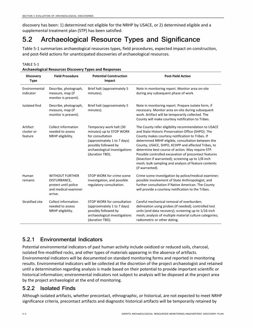
SECTION 5 EVALUATION OF ARCHAEOLOGICAL DISCOVERIES
discovery has been: 1) determined not eligible for the NRHP by USACE, or 2) determined eligible and a supplemental treatment plan (STP) has been satisfied.
5.2 Archaeological Resource Types and Significance Table 5-1 summarizes archaeological resources types, field procedures, expected impact on construction, and post-field actions for unanticipated discoveries of archaeological resources.
TABLE 5-1 Archaeological Resources Discovery Types and Responses
Discovery Type
Field Procedure Potential Construction Impact
Post-Field Action
Environmental indicator
Describe, photograph, measure, map (if monitor is present).
Brief halt (approximately 5 minutes).
Note in monitoring report. Monitor area on-site during any subsequent phase of work.
Isolated find Describe, photograph, measure, map (if monitor is present).
Brief halt (approximately 5 minutes).
Note in monitoring report. Prepare isolate form, if necessary. Monitor area on-site during subsequent work. Artifact will be temporarily collected. The County will make courtesy notification to Tribes.
Artifact cluster or feature
Collect information needed to assess NRHP eligibility.
Temporary work halt (30 minutes) up to STOP WORK for consultation (approximately 1 to 7 days) possibly followed by archaeological investigations (duration TBD).
The County refer eligibility recommendation to USACE and State Historic Preservation Office (SHPO). The County makes courtesy notification to Tribes. If determined NRHP eligible, consultation between the County, USACE, SHPO, KCHPP and affected Tribes, to determine best course of action. May require STP. Possible controlled excavation of precontact features (bisection if warranted); screening up to 1/8-inch mesh; bulk sampling and analysis of feature contents (if warranted).
Human remains
WITHOUT FURTHER DISTURBANCE, protect until police and medical examiner arrive.
STOP WORK for crime scene investigation, and possible regulatory consultation.
Crime scene investigation by police/medical examiner; possible involvement of State Anthropologist, and further consultation if Native American. The County will provide a courtesy notification to the Tribes.
Stratified site Collect information needed to assess NRHP eligibility.
STOP WORK for consultation (approximately 1 to 7 days) possibly followed by archaeological investigations (duration TBD).
Careful mechanical removal of overburden; delineation using probes (if needed); controlled test units (and data recovery); screening up to 1/16-inch mesh; analysis of multiple material culture categories; radiometric or other dating.
5.2.1 Environmental Indicators Potential environmental indicators of past human activity include oxidized or reduced soils, charcoal, isolated fire-modified rocks, and other types of materials appearing in the absence of artifacts. Environmental indicators will be documented on standard monitoring forms and reported in monitoring results. Environmental indicators will be collected at the discretion of the project archaeologist and retained until a determination regarding analysis is made based on their potential to provide important scientific or historical information; environmental indicators not subject to analysis will be disposed at the project area by the project archaeologist at the end of monitoring.
5.2.2 Isolated Finds Although isolated artifacts, whether precontact, ethnographic, or historical, are not expected to meet NRHP significance criteria, precontact artifacts and diagnostic historical artifacts will be temporarily retained by
5-2 GWWTS ARCHAEOLOGICAL RESOURCES MONITORING/INADVERTENT DISCOVERY PLAN

SECTION 5 EVALUATION OF ARCHAEOLOGICAL DISCOVERIES
the archaeological team. When work in an area is complete, the isolated finds will be summarized for discussion among the consulting parties as to the final disposition of the items; artifacts may be curated or reburied on site. In all cases, archaeological isolates will be documented on standard monitoring forms, recorded on an archaeological isolate form(s), and reported in monitoring results.
5.2.3 Artifact Clusters and Features Artifact clusters and features will be recorded on an archaeological site form(s). If artifact clusters or features are identified, the project archaeologist will assess the context and nature of the discovery. In most circumstances, in situ clusters of precontact and ethnographic artifacts or features would be considered eligible. Historical artifact clusters and features may require supplementary archival research to assess their eligibility.
Although, based on current information, this project is not expected to encounter stratified archaeological sites such as camps, housepits, or villages, if such a resource is discovered, the nature, extent, and complexity of any discovery would dictate specific approaches to treatment (see Section 6).
Disturbed sites may be considered eligible if the artifacts are significant, if large volumes of artifacts are found, or if the site is only partially disturbed. Disturbed clusters of historical artifacts, remnants of utilities, and materials younger than 50 years will not be considered significant.
As soon as practical following investigation of any artifact cluster or feature, the project archaeologist will provide the County environmental planner and project representative with a description (written, if possible) of the discovery, as well as a preliminary recommendation regarding potential NRHP eligibility. The County environmental planner will convey this information to USACE and request concurrence. The County environmental planner will also notify KCHPP of the discovery. Concurrence may require several hours (or more), as SHPO is usually available Monday through Thursday only. During this communication process, no ground disturbing work that may cause additional disturbance to the discovery may occur.
If USACE, in consultation with SHPO, determines an artifact cluster or feature not eligible to the NRHP, ground disturbing work may resume once the resource has been documented. Artifacts and features subsamples will be collected and retained until a determination regarding curation is made between consulting parties (see Section 8.0).
If USACE, in consultation with SHPO, determines an artifact cluster or feature eligible to the NRHP, the County project representative will issue a formal Stop Work order. USACE will make a determination regarding Adverse Effects for the eligible resource and notify consulting parties, including SHPO, the Advisory Council on Historic Preservation, the County, KCHPP and affected Tribes. If Adverse Effects cannot be avoided, the County will prepare an STP to resolve any Adverse Effects in consultation with USACE, SHPO, KCHPP, affected Tribes and other consulting parties.
5.3 Special Procedures for the Discovery of Human Remains
If any member of the project team believes he/she has discovered human skeletal remains, all work adjacent to the discovery shall cease immediately. A 30-foot work stoppage area shall be maintained around the discovery. Vehicles, equipment, and unauthorized personnel shall not be permitted to traverse or enter the discovery site.
The County project representative will notify the County environmental planner as soon as possible. The County environmental planner will, in turn, notify King County Medical Examiner and Seattle Police Department, followed by USACE, DAHP, and the KCHPP archaeologist. The medical examiner will assume jurisdiction over the human skeletal remains and make a determination as to whether those remains are forensic (related to a crime) or nonforensic. If the remains are forensic, then the medical examiner will determine appropriate procedures for their disposition. If the remains are nonforensic, the state physical
GWWTS ARCHAEOLOGICAL RESOURCES MONITORING/INADVERTENT DISCOVERY PLAN 5-3

SECTION 5 EVALUATION OF ARCHAEOLOGICAL DISCOVERIES
anthropologist at DAHP will assume jurisdiction over the remains and will contact appropriate tribes and cemeteries. The state physical anthropologist at DAHP will make a determination as to whether the remains are Indian or non-Indian and report that finding to appropriate tribes and cemeteries.
The DAHP will handle all consultation with the affected parties as to the future preservation, excavation, and disposition of the remains. No persons other than the proper law enforcement personnel, the project archaeologist (or archaeological monitor), KCHPP archaeologist, and DAHP staff shall be authorized direct access to the discovery location after the area is secured. Construction excavations may continue outside the work stoppage area during a human remains discovery response.
5-4 GWWTS ARCHAEOLOGICAL RESOURCES MONITORING/INADVERTENT DISCOVERY PLAN

SECTION 6
Supplemental Treatment Plans Preparing an STP is part of the Section 106 process to resolve an adverse effect upon resources that are determined eligible to the NRHP. Preparing and implementing such a plan satisfies USACE responsibilities under Section 106 (CFR 800.13 [a][2]). An STP would be prepared in a manner consistent with the Secretary of the Interior’s Standards for Archaeological Documentation (48 FR 44734–44737) and the ACHP’s Treatment of Archaeological Properties (Advisory Council on Historic Preservation 1980). An STP would also be responsive to applicable Washington regulations, including SHPO’s Standards for Cultural Resource Reporting (2008). Such a plan would modify this document to be site- and property-specific and include proposed measures to mitigate or avoid adverse effects to eligible properties.
An STP would include a research design, research problems, and research questions; methodologies for investigation and data analysis; plans for report preparation; and curation of materials and records. Specific research questions would focus on the attributes of the archaeological deposits that are discovered, in the context of research domains that can be addressed within the APE.
An STP would emphasize the acquisition of those data that contribute to understanding the particular site and its place in regional prehistory, ethnohistory, or history. The proposed research design applicable to the GWWTS project would consist of two sections: research problems and methodology. The research problems section would provide research domains and questions that would be addressed at each location. The methodology section would provide standard field and laboratory methods that can form a basis from which more detailed investigations of significant historical properties can be developed. Each STP will set forth resource-specific requirements for collection and curation of any particular archaeological resource.
Because discovery of an eligible property would occur during active construction, review of STPs would be expected to be conducted under an expedited (“emergency”) timeline if possible:
• Within 2 working days of USACE’s determination of adverse effect on an eligible property, the County will submit an STP to USACE for review and distribution to consulting parties.
• Consulting parties will review and provide comments and/or objections to USACE. If revision to the STP is needed, consulting parties would review revisions.
• Once finalized, the County will provide a final STP to USACE for distribution to consulting parties.
6.1 Implementing and Satisfying Supplemental Treatment Plan
The project archaeologist will implement the STP with the goal of minimizing potential delays to active construction; measures to expedite completion of the STP will be implemented as possible. Measures to expedite the completion of the STP will vary depending on the type of discovery and the time required to complete the work and may include working extended hours each day, working weekends, or working 7 days per week. USACE will issue authorization to proceed with ground disturbing work in those segments of the project that contain archaeological properties once treatment specified in the STP has been completed.
GWWTS ARCHAEOLOGICAL RESOURCES MONITORING/INADVERTENT DISCOVERY PLAN 6-1


SECTION 7
Communications and Reporting This section outlines communication procedures for archaeological resource matters that arise during project construction. Communication will include: face-to-face meetings regarding construction monitoring; routine, daily or weekly, communication between the archaeological monitoring team and the County personnel (minimally, environmental planner and construction management personnel) regarding project schedules, and construction plan drawings and maps; and formal monitoring reports, letters, and recording forms. The authority to communicate a Stop Work order rests with the County.
A cultural resources contact list is provided in Appendix A. The project archaeologist will finalize the contact list prior to construction.
7.1 Final Construction Plan Review Prior to construction, the project archaeologist will review final construction plans to verify that needs for archaeological monitoring conform with the ARMP. If changes to the ARMP are needed, the project archaeologist will confer with the County environmental planner.
7.2 Preconstruction Meeting Pre-construction meeting(s) will be held the between the project archaeologist, the County construction management personnel, contractor project managers, and construction supervisors involved in ground disturbing construction. The Tribes will be invited to attend the preconstruction meeting. Meetings will serve to accomplish the following:
• Review construction plans, schedules, and areas where monitoring will take place.
• Describe the role of archaeological monitoring in the construction process.
• Establish a chain of command for communication and decision-making among the County, the project archaeologist, and construction personnel.
• Provide personal introductions among the County, the project archaeologist, and construction personnel who will be working together.
• Clarify any questions about schedules, construction locations, construction techniques, or notification procedures.
7.3 Cultural Resources Orientations The project archaeologist will provide an orientation regarding cultural resource concerns for the project area, types of resources that might be encountered, and protocols to the County construction management personnel, Contractor, and Subcontractor Leads prior to construction; this orientation may be held in conjunction with pre-construction meetings described in Section 7.2 (above).
Additionally, the project archaeologist or archaeological monitor will provide a 10-minute on-site cultural resources orientation (“tailgate”) to all construction crew members prior to their first day on-site. The project archaeologist will furnish a hardhat sticker to identify construction personnel as having received cultural resources orientation. The number of tailgate orientations needed is to be determined.
7.4 Ongoing Communications The project archaeologist will remain in regular communication with the County construction management personnel, as well as the County environmental planner, before and throughout construction via email and
GWWTS ARCHAEOLOGICAL RESOURCES MONITORING/INADVERTENT DISCOVERY PLAN 7-1

SECTION 7 COMMUNICATIONS AND REPORTING
phone. The County construction management will provide current project schedules and plans to the project archaeologist as they are updated. This communication will accomplish the following:
• Provide the appropriate archaeology staffing level for monitoring.
• Provide advance warning of hazardous waste situations and requirements for HAZWOPER-trained personnel with personal protective equipment.
• Ensure the project archaeologist is receiving up-to-date construction plans. These drawings must show all planned ground disturbance.
• Inform the County personnel, contractor, and subcontractor leads of potentially significant archaeological resources so that the resources can be adequately protected and studied.
7.5 On-Site Communications Archaeological monitors or on-call archaeologist will communicate with the County construction management personnel to make general requests about equipment movement, placement of spoils for examination, access to exposures, and temporary halts in excavation for the purpose of examining potential archaeological resources.
7.6 Weekly Progress Summaries The project archaeologist will submit brief progress reports of monitoring activities to the County environmental planner each week via email. The emails will be based on a summary of the daily log of activities submitted by archaeological monitors and on-call archaeologists.
7.7 Monthly Progress Reports The project archaeologist will prepare and submit monthly progress reports to the County environmental planner; the progress reports will summarize all activities that have taken place during each calendar month. The monthly reports will include projections of future project work. Monthly progress reports might include video documentation if significant resources are found.
7.8 Communication with Tribes This section summarizes the communications that will be conducted with the affected Tribes. The County will invite the affected Tribes to attend the pre-construction meeting. The County will provide a courtesy notification if isolated artifacts, features, or other cultural resources are identified during monitoring; the purpose of the notification is to allow the Tribes to prepare for determination of eligibility during official consultation. The County will provide a courtesy notification to the affected Tribes if human remains are identified; the purpose of the notification is to allow the Tribes to prepare for official notice from DAHP. The project archaeologist will include the affected Tribes in weekly and monthly progress reports.
7.9 Monitoring Report The project archaeologist will submit a draft report of results to the County within 60 days of completion of all monitoring for the project. The report will include information on how the monitoring was conducted and a brief analysis and summary narrative discussion of any artifacts or cultural deposits encountered. The County will distribute the draft report to USACE who will distribute it for comment by KCHPP, affected Tribes, DAHP, and others at its discretion. The project archaeologist will submit the final report within 14 days of receiving a consolidated set of reviewer comments from the County. The County will be responsible for submitting the final report to USACE for distribution to the consulting parties.
7-2 GWWTS ARCHAEOLOGICAL RESOURCES MONITORING/INADVERTENT DISCOVERY PLAN

SECTION 7 COMMUNICATIONS AND REPORTING
7.10 Dissemination of Communications The County will keep all other consulting parties informed, as appropriate. Consultation among the County, USACE, KCHPP, DAHP, Tribal governments, and other entities will be initiated under the circumstances previously noted concerning the discovery of burials or sites that are potentially NRHP-eligible. The project archaeologist will be informed of decisions made during the consultation process.
GWWTS ARCHAEOLOGICAL RESOURCES MONITORING/INADVERTENT DISCOVERY PLAN 7-3


SECTION 8
Archaeological Resources Collection and Curation Archaeological resources encountered during monitoring will be recorded in daily monitoring logs and collected. Resources determined eligible by USACE will curated in a facility that meets Code of Federal Regulations Title 36, Part 79 standards. Resources determined not eligible by USACE will be disposed as part of the construction waste stream or reburied on site, unless requested otherwise by the County. Archaeological resources encountered during fulfillment of an STP will be collected and curated according to terms set forth in that STP. 36 CFR Part 79 requires that associated records that are prepared in compliance with Section 106 (§79.4(a)(2)(v)) must be curated in a facility that meets Part 79 standards. The County will meet with affected Tribes in advance of construction to discuss the selection of a curation facility.
GWWTS ARCHAEOLOGICAL RESOURCES MONITORING/INADVERTENT DISCOVERY PLAN 8-1


SECTION 9
References Baist Map Company
1908 Surveys of Seattle. Baist Map Company, Seattle. On file, Seattle Public Library. 1912 Surveys of Seattle. Baist Map Company, Seattle. On file, Seattle Public Library.
Bucknam, R.C., E. Hemphill-Haley, and E.B. Leopold 1992 Abrupt uplift within the past 1700 years at Southern Puget Sound. Washington Science 258:1611-
1614.
CH2M HILL Engineers, Inc. (CH2M) 2015 Georgetown Wet Weather Treatment Station Preliminary Geotechnical Assessment. On file at ESA,
Seattle.
CH2M HILL Engineers, Inc., HDR, Inc., and Associated Firms 2016 Georgetown Wet Weather Treatment Station Facility Plan. On file at ESA, Seattle.
Department of Archaeology and Historic Preservation (DAHP) 2015 Washington State Standards for Cultural Resources Reporting. Last updated 2015. Electronic
document, http://www.dahp.wa.gov/sites/default/files/CR%20Update%202015%282%29.pdf, accessed November 18, 2015.
2010 Statewide Predictive Model. Last updated 2010. Electronic document, http://www.dahp.wa.gov/, accessed June 24, 2015.
Dragovich, Joe D., Patrick T. Pringle, and Timothy Walsh 1994 Extent and Geometry of the Mid-Holocene Osceola Mudflow in the Puget Lowland – Implications
for Holocene Sedimentation and Paleogeography. Washington Geology 22(3):3-26.
Hilbert, Vi, Jay Miller, and Zalmai Zahir 2001 Puget Sound Geography: Original Manuscript from T. T. Waterman. Lushootseed Press, Seattle.
Available from Zahir Consulting Services, Federal Way, WA.
King County Department of Natural Resources (KCDNR) 2001 Reconnaissance Assessment of the State of the Nearshore Ecosystem: Eastern Shore of Central
Puget Sound, Including Vashon and Maury Islands (WRIAs 8 and 9).
Ostrander, Thomas, Katherine F. Wilson, Chris Lockwood, Chanda Schneider, and Paula Johnson 2016 Georgetown Wet Weather Treatment Station Cultural Resources Assessment. Prepared for King
County Wastewater Treatment Division. Prepared by Environmental Science Associates, Seattle.
ten Brink, U.S., J. Song, and R.C. Bucknam 2006 Rupture models for the A.D. 900-930 Seattle fault earthquake from uplifted shorelines. Geology
34:585-588.
Thrush, Coll-Peter 2002 The Crossing-Over Place: Urban and Indian Histories in Seattle. Ph.D. dissertation, University of
Washington, Seattle. University Microfilms, Ann Arbor, MI. 2007 Native Seattle: Histories from the Crossing Over Place. University of Washington Press, Seattle, WA.
GWWTS ARCHAEOLOGICAL RESOURCES MONITORING/INADVERTENT DISCOVERY PLAN 9-1
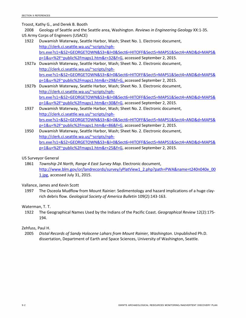
SECTION 9 REFERENCES
Troost, Kathy G., and Derek B. Booth 2008 Geology of Seattle and the Seattle area, Washington. Reviews in Engineering Geology XX:1-35.
US Army Corps of Engineers (USACE) 1922 Duwamish Waterway, Seattle Harbor, Wash; Sheet No. 1. Electronic document,
http://clerk.ci.seattle.wa.us/~scripts/nph-brs.exe?s1=&S2=GEORGETOWN&S3=&l=0&Sect6=HITOFF&Sect5=MAPS1&Sect4=AND&d=MAPS&p=1&u=%2F~public%2Fmaps1.htm&r=32&f=G, accessed September 2, 2015.
1927a Duwamish Waterway, Seattle Harbor, Wash; Sheet No. 2. Electronic document, http://clerk.ci.seattle.wa.us/~scripts/nph-brs.exe?s1=&S2=GEORGETOWN&S3=&l=0&Sect6=HITOFF&Sect5=MAPS1&Sect4=AND&d=MAPS&p=1&u=%2F~public%2Fmaps1.htm&r=29&f=G, accessed September 2, 2015.
1927b Duwamish Waterway, Seattle Harbor, Wash; Sheet No. 3. Electronic document, http://clerk.ci.seattle.wa.us/~scripts/nph-brs.exe?s1=&S2=GEORGETOWN&S3=&l=0&Sect6=HITOFF&Sect5=MAPS1&Sect4=AND&d=MAPS&p=1&u=%2F~public%2Fmaps1.htm&r=30&f=G, accessed September 2, 2015.
1937 Duwamish Waterway, Seattle Harbor, Wash; Sheet No. 2. Electronic document, http://clerk.ci.seattle.wa.us/~scripts/nph-brs.exe?s1=&S2=GEORGETOWN&S3=&l=0&Sect6=HITOFF&Sect5=MAPS1&Sect4=AND&d=MAPS&p=1&u=%2F~public%2Fmaps1.htm&r=86&f=G, accessed September 2, 2015.
1950 Duwamish Waterway, Seattle Harbor, Wash; Sheet No. 2. Electronic document, http://clerk.ci.seattle.wa.us/~scripts/nph-brs.exe?s1=&S2=GEORGETOWN&S3=&l=0&Sect6=HITOFF&Sect5=MAPS1&Sect4=AND&d=MAPS&p=1&u=%2F~public%2Fmaps1.htm&r=25&f=G, accessed September 2, 2015.
US Surveyor General 1861 Township 24 North, Range 4 East Survey Map. Electronic document,
http://www.blm.gov/or/landrecords/survey/yPlatView1_2.php?path=PWA&name=t240n040e_001.jpg, accessed July 31, 2015.
Vallance, James and Kevin Scott 1997 The Osceola Mudflow from Mount Rainier: Sedimentology and hazard implications of a huge clay-
rich debris flow. Geological Society of America Bulletin 109(2):143-163.
Waterman, T. T. 1922 The Geographical Names Used by the Indians of the Pacific Coast. Geographical Review 12(2):175-
194.
Zehfuss, Paul H. 2005 Distal Records of Sandy Holocene Lahars from Mount Rainier, Washington. Unpublished Ph.D.
dissertation, Department of Earth and Space Sciences, University of Washington, Seattle.
9-2 GWWTS ARCHAEOLOGICAL RESOURCES MONITORING/INADVERTENT DISCOVERY PLAN

Appendix A Cultural Resources Contact List


Appendix A—Georgetown Wet Weather Treatment Station Cultural Resources Contacts
UPDATE PRIOR TO CONSTRUCTION
Seattle Police Department (non-emergency) (206) 625-5011
King County Medical Examiner (206) 731-3232
USACE (Seattle District)
Chris Jenkins, Cultural Resources Program Manager (206) 764-6909
Lance Lundquist, Archaeologist (206) 764-6909
Department of Archaeology and Historic Preservation
Dr. Rob Whitlam, State Archaeologist (360) 586-3080
Dr. Guy Tasa, State Physical Anthropologist (360) 586-3534
King County Wastewater Treatment Division
TBD (206) xxx-xxxx
King County Historic Preservation Program
Philippe D. LeTourneau, Archaeologist (206) 477-4529
Project Archaeologist
TBD
Tribes
TBD


August 2017 C01072C17 ENVIRONMENTAL CONTROLS Georgetown Wet Weather Treatment Station 01561 - 1 FOR MARINE CONSTRUCTION
SECTION 01561
ENVIRONMENTAL CONTROLS FOR MARINE CONSTRUCTION
PART 1 GENERAL
1.01 SUMMARY
A. This Section specifies environmental controls specific to marine construction in and over the Duwamish Waterway, pursuant to permits issued to King County and Washington State Water Quality Standards for protection of water quality and aquatic resources.
B. Permits and easements are included in Section 01062 of these Contract Documents. Contractor shall be responsible for all permit and easement requirements, whether referenced in this Section or not.
1.02 AQUATIC PERMIT REFERENCES
A. The following list includes selected permits issued to King County that include stipulations for protection of the aquatic environment, and other documents that are referenced in the permits and are binding on Contractor operations: 1. HPA – Hydraulic Project Approval Permit No. 2017-4-139+01 issued March 09, 2017 by
Washington Department of Fish and Wildlife (Section 01062), includes abiding with the following: a. MMP – Mitigation and Monitoring Plan dated March 2016 by Environmental Science
Associations (Section 01012). 2. NPW7 – Nationwide Permit 7 Authorization from U.S. Army Corps of Engineers June 23, 2017,
Reference No. NWS-2016-17 (Section 01062), includes abiding with the following: a. Bo – Endangered Species Act Section 7(a)(2) Biological Opinion dated July 28, 2016 by U.S.
Department of Commerce, National Oceanic and Atmospheric Administration, National Marine Fisheries Service, NMFS Reference No. WCR-2016-4157 (Section 01012).
b. BA – Biological Assessment and EFH Assessment dated December 2015 by Environmental Science Associates (Section 01012).
3. SSDP – Shoreline Substantial Development Permit dated May 2, 2016 by City of Seattle, Department of Construction and Inspections (Section 01062).
4. MIT – Agreement between Muckleshoot Indian Tribe and King County dated May 5, 2017 (Section 01062).
5. ST – Agreement between Suquamish Tribe and King County dated May 25, 2017 (Section 01062).
B. All documents listed above are included in Volume 5 of these Contract Documents.
1.03 SUBMITTALS
A. Procedures: Section 01300.
B. Turbidity Monitoring Plan and its revisions.
C. Qualifications for: 1. Contractor’s responsible party for permit compliance. 2. Subcontractor firm and responsible party of turbidity monitoring and reporting.
D. Barge Staging and Vessel Traffic Plan and its revisions.

August 2017 C01072C17 ENVIRONMENTAL CONTROLS Georgetown Wet Weather Treatment Station 01561 - 2 FOR MARINE CONSTRUCTION
1.04 TURBIDITY MONITORING PLAN
A. Contractor shall hire a qualified subcontractor who shall prepare and execute turbidity monitoring as specified in this Section.
B. The plan shall establish personnel, equipment, monitoring stations frequencies, and communication protocol for turbidity monitoring as specified in this Section.
1.05 BARGE STAGING AND VESSEL TRAFFIC PLAN
A. At least five months prior to initiating any barge movements or other floating structures, submit a Barge Staging and Vessel Traffic Plan to King County for review and approval by Suquamish Tribe and Muckleshoot Indian Tribe, establishing on-site and off-site locations, durations, and times.
B. Contractor shall attend one meeting with Muckleshoot Indian Tribe and one meeting with Suquamish Tribe, if requested by King County, to coordinate and reach mutual agreement on barge and vessel traffic before they are initiated.
C. See Section 02628 for additional requirements for barge staging and vessel movements, to be included in the Plan.
1.06 WATER QUALITY STANDARDS
A. Construction activities shall not cause exceedance of Washington State Water Quality Standards WAC 173-201A in the Lower Duwamish Waterway.
PART 2 PRODUCTS (NOT USED)
PART 3 EXECUTION
3.01 AQUATIC PERMIT SUMMARY TABLE
A. Table 1 summarizes key provisions of the listed aquatic permits and reference documents. It is not inclusive of all requirements and obligations of the Contractor for protection of water and sediment quality and aquatic resources in Duwamish Waterway. Table 1 includes the following summaries: 1. Itemizes specific actions or environmental controls from aquatic permits and reference
documents. 2. References to the permits and documents from Part 1.02 of this Section that include the
stipulation. 3. Clarification where redundancies or inconsistencies may exist among permits. 4. Contractor and King County obligations for compliance with listed conditions. 5. References to other Specification Sections with relevant operational requirements.

August 2017 C01072C17 ENVIRONMENTAL CONTROLS Georgetown Wet Weather Treatment Station 01561 - 3 FOR MARINE CONSTRUCTION
Table 1. Key Aquatic Permit Conditions Summary Table.
Agency/Permit Reference Provision Responsible Party Specification
Reference HPA #1 NWP7 BO Sect. 1.3 BA Sect 2.7 SSDP pg. 3 MIT ST
In-water Work Window: 1. Work below the Ordinary High Water line shall
occur only between October 1 and February 15. 2. Ordinary High Water is defined as Mean Higher
High Water (MHHW) tide elevation, which is shown on the Drawings.
3. In-water work shall be completed within a single work window, October 1, 2018 through February 15, 2019.
4. No in-water work shall be conducted below mean lower low tide (MLLW) elevation between October 1 and November 25, except for placement of silt curtains and movement of work skiffs.
Abide: Contractor 01014 1.07
BO Sect. 2.8 HPA #16 HPA #46 HPA #47 HPA #48 HPA #49 HPA #50
Turbidity/Suspended Sediment: 1. Monitor turbidity at the point of compliance, which
shall be at a distance of 150 feet from the activity causing turbidity.
2. Do not exceed 340 NTU for three hours at the point of compliance.per ESA Section 7 National Marine Fisheries Biological Opinion
3. Do not exceed Washington State water quality standards at the point of compliance.
4. Stop work until turbidity criterions are met. 5. Modify construction means and methods as
necessary to meet turbidity criterions.
Abide: Contractor 01561 3.02 02271
BO Sect. 2.8 BA Sect. 2.8 MMP Sect. 5.5 SSDP pg. 7
Habitat Disruption: 1. Total area of pipeline, concrete anchors and quarry
spall backfill shall not exceed 1,200 sq. ft.
Abide: Contractor Confirmation survey and report to agencies: King County
02323 3.04.D.2
BA Sect 2.7 HPA #40 MMP Sect. 2.1.2.1
Nearshore/Intertidal Trench Containment: 1. Enclosed sheet pile cofferdam required above
approx. +1 ft. MLLW elevation. 2. Waterstop required for cofferdam sheets to
minimize water leakage to waterway.
Design: Contractor Abide: Contractor
02161
BA Section 2.7 HPA #40 MMP Sect. 2.1.2.2
Offshore Trench Containment: 1. Sheet pile trench containment required approx. +1
ft. MLLW to -12 ft. MLLW elevation.
Design: Contractor Abide: Contractor
02161

August 2017 C01072C17 ENVIRONMENTAL CONTROLS Georgetown Wet Weather Treatment Station 01561 - 4 FOR MARINE CONSTRUCTION
Table 1. Key Aquatic Permit Conditions Summary Table.
Agency/Permit Reference Provision Responsible Party Specification
Reference 2. Trench open to waterway at end, with silt
containment curtain. BA Section 2.7.4 HPA #47 MMP Sect. 2.1.2.3
Diffuser Laid on Grade between WSDOT Structures: 1. Excavation using hydraulic suction dredging only,
no release to waterway. 2. Jetting not allowed.
Abide: Contractor 02323
BA Section 2.7.1 HPA #40 MMP Sect. 2.1.2.4
Trestle: 1. Temporary work trestle (work bridge) of up to 2,900
sq. ft. beyond MHHW may be constructed. 2. Trestle structure shall be integrated with trench
sheeting using pipe piles. 3. Debris containment BMP required beneath work
bridge deck.
Design: Contractor Abide: Contractor
02161
HPA #43 HPA #44
Pile Driving: 1. Use vibratory driving hammer preferentially over
impact hammer. 2. If impact hammer used, follow approved noise
attenuation methods.
Abide: Contractor 02161
HPA #39 HPA #20 HPA #45 MMP Sect. 5.5 BA Section 2.8
Removal and Disposal of Piling and Debris: 1. Follow prescribed BMPs for removal, handling and
disposal of existing piles. 2. Remove and dispose of sunken dock and concrete
rubble and debris on shoreline.
Abide: Contractor 02050
HPA #28 MMP Sect. 5.3
Fish Habitat Substrate Placement: 1. Install to minimum depth of 12 inches where shown
on Drawings
Abide: Contractor 02323 3.04.D.1
HPA #19 Temporary Stormwater Bypass: 1. Install, operate and maintain stormwater bypass of
existing stormwater swale
Abide: Contractor 02601
HPA #5 Photographs: 1. Photographs of the job site before the work begins
and after the work is completed must be taken. 2. Submit to WDFW within 30 days after completion
of work.
Photographs: Contractor Submit to WDFW: King County
01380
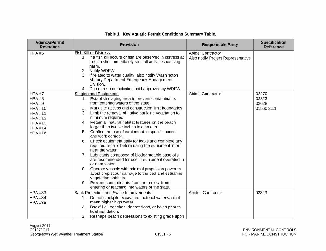
August 2017 C01072C17 ENVIRONMENTAL CONTROLS Georgetown Wet Weather Treatment Station 01561 - 5 FOR MARINE CONSTRUCTION
Table 1. Key Aquatic Permit Conditions Summary Table.
Agency/Permit Reference Provision Responsible Party Specification
Reference HPA #6 Fish Kill or Distress:
1. If a fish kill occurs or fish are observed in distress at the job site, immediately stop all activities causing harm.
2. Notify WDFW. 3. If related to water quality, also notify Washington
Military Department Emergency Management Division.
4. Do not resume activities until approved by WDFW.
Abide: Contractor Also notify Project Representative
HPA #7 HPA #8 HPA #9 HPA #10 HPA #11 HPA #12 HPA #13 HPA #14 HPA #16
Staging and Equipment: 1. Establish staging area to prevent contaminants
from entering waters of the state. 2. Mark site access and construction limit boundaries. 3. Limit the removal of native bankline vegetation to
minimum required. 4. Retain all natural habitat features on the beach
larger than twelve inches in diameter. 5. Confine the use of equipment to specific access
and work corridor. 6. Check equipment daily for leaks and complete any
required repairs before using the equipment in or near the water.
7. Lubricants composed of biodegradable base oils are recommended for use in equipment operated in or near water.
8. Operate vessels with minimal propulsion power to avoid prop scour damage to the bed and estuarine vegetation habitats.
9. Prevent contaminants from the project from entering or leaching into waters of the state.
Abide: Contractor 02270 02323 02628 01560 3.11
HPA #33 HPA #34 HPA #35
Bank Protection and Swale Improvements: 1. Do not stockpile excavated material waterward of
mean higher high water. 2. Backfill all trenches, depressions, or holes prior to
tidal inundation. 3. Reshape beach depressions to existing grade upon
Abide: Contractor 02323

August 2017 C01072C17 ENVIRONMENTAL CONTROLS Georgetown Wet Weather Treatment Station 01561 - 6 FOR MARINE CONSTRUCTION
Table 1. Key Aquatic Permit Conditions Summary Table.
Agency/Permit Reference Provision Responsible Party Specification
Reference completion.
HPA #46 HPA #47 HPA #48 HPA #49 HPA #50 HPA #51
Dredging: 1. Conduct dredging with dredge types and methods
that cause the least impacts to fish and shellfish. 2. Operate a hydraulic dredge with the intake at or
below the bed surface. Raise the intake up to three feet above the bed only for brief periods of purging or flushing the intake system.
3. Operate a dragline or clamshell to minimize turbidity. During excavation, complete each pass with the clamshell or dragline bucket. Do not stockpile dredged material waterward of the ordinary high water line.
4. Dispose of dredged bed materials in an approved upland disposal site landward of the ordinary high water line.
5. To minimize turbidity, hopper dredges, scows and barges used to transport dredged materials to the disposal or transfer sites must completely contain the dredged material.
6. To avoid attracting fish to artificial light at night, limit dredging activities to daylight hours whenever feasible.
Abide: Contractor 02323 02050 02060
HPA #56 Planting Plan: 1. The shoreline must be replanted per the planting
plan dated August 2016. 2. Maintenance, monitoring and survival requirements
are stipulated in the HPA
Abide: Contractor 02900
MIT ST
Impacts on Tribal Fishing: 1. Compensate Tribes for net moves, gear damage,
and lost time claims per Provision 4 in each Tribal Agreement.
Abide: Contractor 01014 01500 1.24

August 2017 C01072C17 ENVIRONMENTAL CONTROLS Georgetown Wet Weather Treatment Station 01561 - 7 FOR MARINE CONSTRUCTION
3.02 TURBIDITY MANAGEMENT AND MONITORING
A. Turbidity monitoring shall be conducted at any time construction creates sediment plumes in the Duwamish Waterway, including non-working hours when currents or tidal conditions may result in sediment plumes from idle working areas.
B. Turbidity shall be monitored at the point of compliance, which shall be at a distance of 150 feet from the activity causing turbidity, when a sediment plume is observed or a sediment plume is anticipated.
C. Turbidity shall not exceed 340 nephelometric turbidity units (NTU) at the point of compliance for greater than three hours exposure time.
D. Turbidity shall not exceed Washington State water quality standards as specified in Section 02271.
E. Contractor shall adjust construction means and methods to meet this criterion, employing best management practices (BMPs) established in the permits and references in this Section. Contractor shall stop work until turbidity criterion is met at no additional cost to King County.
3.03 IN-WATER CONSTRUCTION BMPs
A. Required BMPs for in-water construction include (Note: Upland BMPs for erosion and sediment control, spill prevention and countermeasure, and stormwater pollution prevention are specified elsewhere in these specifications.): 1. All pollutants will be handled in a manner that will not contaminate the water or substrate of the
Lower Duwamish Waterway (LDW). 2. No maintenance or fueling of construction equipment or land-based vehicles will be allowed
within, above, or immediately adjacent of the LDW. Equipment on board barges shall be fueled within spill containment BMPs established in the Spill Plan per Section 01560. Skiff refueling shall be conducted upland.
3. Materials that modify pH, such as cement, cement grindings, and cement saw cutting, will be managed so that they will not contaminate surface water runoff or otherwise enter the LDW.
4. Cofferdams and silt curtains will be used for worksite isolation during in-water excavation work, to contain suspended sediment. These elements will be installed during low tides to minimize fish stranding.
5. Any water pumped from the sheet pile enclosure will undergo adequate treatment and will be discharged appropriately, adhering to all applicable water quality standards.
6. Floating booms will be used to contain any debris that could enter the water during construction. 7. A containment system, whether on or under the temporary work trestle, will be installed to capture
any debris from the construction work on the temporary work trestle and prevent debris entry into the LDW.
8. Work barges will be monitored for overall displacement against expected tides to avoid grounding in shallow depths along shoreline.
9. Low draft skiffs will be used to prevent sediment disturbance from prop wash. 10. The project will use tugs to move and position work barges, and spuds will hold barges in place
while completing work. 11. The project will use a variety of BMPs to ensure safe handling, storage, and transport of
contaminated or potentially contaminated river sediments and substrate (e.g., spill aprons, drop curtains, gated hoppers operating from fixed locations, sealed containers, etc.).
12. The Contractor shall furnish, install, and operate a temporary noise attenuation system such as a bubble curtain, Temporary Nosie Attenuation Pile (TNAPs), or a functional equivalent for all in-water impact pile driving activities.
13. The proponent will implement protocols for waste sampling and characterization. Any characteristically hazardous or toxic waste (or wastewater) will be disposed according to all applicable state and Federal requirements, at an approved upland disposal site or at an approved in-water dredged material disposal site.
END OF SECTION

August 2017 C01072C17 ENVIRONMENTAL CONTROLS Georgetown Wet Weather Treatment Station 01561 - 8 FOR MARINE CONSTRUCTION
This page intentionally left blank.

August 2017 C01072C17 Georgetown Wet Weather Treatment Station 01570 - 1 TRAFFIC REGULATION
SECTION 01570
TRAFFIC REGULATION
PART 1 GENERAL
1.01 SUMMARY
A. This Section specifies the requirements for traffic control plans, notification schedules, temporary barricades, signs, flaggers, lights, road surfaces, detours, and maintenance thereof; and other safeguards necessary to protect life, health and safety.
1.02 QUALITY ASSURANCE
A. Referenced Standards: This Section incorporates by reference the latest revisions of the following documents. These references are a part of this Section as specified and modified. In case of conflict between the requirements of this Section and those of the listed documents, the requirements of this Section shall prevail. Reference Title MUTCD U.S. Department of Transportation, Federal Highway Administration: Manual on
Uniform Traffic Control Devices, Part VI "Work Zone Traffic Control Standards and Guidelines"
SMC Title 15 Director’s Rule 10-2015: Pedestrian Mobility In and Around Work Zone
1.03 SUBMITTALS
A. Procedures: Section 01300.
B. Traffic Control Plans: 1. Submit to Project Representative. Project Representative will coordinate review with the Local
Authority Having Jurisdiction (LAHJ). 2. Plan on additional review time for review by LAHJ.
C. Notification plan and schedules.
1.04 TRAFFIC CONTROL PLANS
A. Comply with the requirements of the LAHJ.
B. Identify specific streets which will have a traffic impact.
C. Annotate location of barricades, lighting, signing, temporary striping, and other traffic control devices.
D. Include the length of time that the Traffic Control Plans will be in place at each location.
E. Show access to buildings, emergency exiting, or property within and immediately adjacent to construction Site.
F. Anticipate traffic, bus zone and driveway relocation resulting from construction operations. Include anticipated loss of bus, passenger, and truck loading zones.
G. Provide location of on street parking.
H. Provide plan for full road closures and design of the detour route for local access.

August 2017 C01072C17 Georgetown Wet Weather Treatment Station 01570 - 2 TRAFFIC REGULATION
1.05 TRAFFIC CONTROL REQUIREMENTS
A. Work shall not impact two consecutive street intersections at the same time.
B. Maintain pedestrian and bicycle access. Work with the Project Representative if pedestrian and bicycle pathways require temporary rerouting or closure.
C. Traffic flow on streets where work is not being performed shall not be revised.
D. Traffic flow on minor arterial streets shall be maintained in each direction.
E. Unless otherwise indicated, provide for passage and access of emergency vehicles, police, fire, and disaster units. Assume liability for damages resulting from failure to provide said access.
F. Use off duty police officers when affecting normal traffic operation at a signalized intersection.
G. Vehicular and pedestrian routing on streets where the work is not being performed shall not be revised.
H. Where a two-way roadway is restricted to one lane of two-way traffic, provide a minimum of two certified flaggers in order to insure safe and effective planning of traffic through the constricted zone. Provide three certified flaggers when the construction zone length causes sight distance or communication problems between a two-member team of flaggers to operate safely.
I. Lane restrictions for specific roadways shall be the following unless otherwise approved by the LAHJ in writing: 1. For roadways that remain open during construction, maintain two-way traffic 7-9 a.m. and 4-6
p.m. weekdays. Each traffic lane shall be at least 12 feet in width. 2. Maintain one lane with flaggers at other times. Lane shall be at least 12 feet in width.
J. Provide a minimum of seven days notice to Project Representative and private property owner when driveway access will be restricted. 1. Provide cleared residential driveway access at the end of every work day. 2. Provide businesses, public service buildings, and industrial sites driveway access during their
operating hours. 3. Provide and maintain signage in accordance with this Section and as indicated in the Traffic
Control Plan.
K. Obtain appropriate approvals from both the Police Department and the Fire Department prior to street closures.
L. Within the construction zones, provide parking restrictions and easels in accordance with the requirements of the LAHJ. If there are no LAHJ requirements, at a minimum, provide parking easels within 2 days in advance of the need to clear parking. Keep parking restrictions to a minimum.
M. Provide the services of a uniformed police officer during working hours in the construction zone when signalized intersections are affected by construction to direct traffic, countermand the traffic signal and if necessary, to clear traffic backups. This officer is not for the convenience of the Contractor but rather to facilitate traffic movements.
N. Provide local access to businesses, industrial sites and residences. Provide a certified flagger to prevent any conflicts between local access traffic and construction crews and/or heavy equipment whenever local access is required into/out of the construction zone.

August 2017 C01072C17 Georgetown Wet Weather Treatment Station 01570 - 3 TRAFFIC REGULATION
O. Provide road closure plans and provide for the type of traffic impacted. Provide design of the detour route for local access.
P. Provide concrete barriers to separate traffic flow from construction work.
Q. Channel traffic flow into the work zone per the Traffic Control Plan.
R. Provide a temporary 5-foot wide alternate pathway on the same side of the street when construction interferes with the usual pedestrian/cyclist pathways. Keep pedestrian/ cyclist, vehicles and open excavations along the arterial separate from one another to meet safety requirements. Maintain minimum of three crosswalks at affected intersections.
S. Maintain access to Muckleshoot Tribe’s boat storage yards, fish processing facility, and boat ramp east of SR 99/509 Bridge.
1.06 JOB COORDINATION
A. Coordinate construction to offer the least possible obstruction and inconvenience to public.
B. Coordinate with property and business owners in order to maintain convenient access for local traffic to private properties along the line of work and as specified in this Section and indicated in the Drawings.
C. Keep existing street lighting systems in operation during progress of the work unless otherwise indicated.
D. Do not open up sections of work and leave them unfinished unless protected. Finish work in progress insofar as practicable.
E. Have under construction no greater length or amount of work than can be prosecuted properly with due regards to the rights of the public.
F. Coordinate revisions to existing traffic control with the affected agencies. Keep traffic controls in operation, unless otherwise required by the Project Representative, for the benefit of the traveling public during progress of the work.
G. As work progresses and as conditions permit, reset temporarily relocated or removed traffic and street name signs in their permanent location. Replace or repair signs and other traffic control devices damaged or lost.
H. Coordinate with property owners or designated representatives and service providers for uninterrupted garbage/recycling collection, mail, and other delivery services.
1.07 NOTIFICATIONS PLANS AND SCHEDULES
A. Update as necessary for the weekly Contract meetings and include the following addresses of affected business/property owners and the estimated dates and number of days construction will be within 150 feet of the addresses and fronting the properties.
B. Prepare a Notification Plan within 30 days of the effective date of the Notice to Proceed and update for weekly Contract meetings a Notification Schedule to maintain access for adjacent or affected properties and businesses.

August 2017 C01072C17 Georgetown Wet Weather Treatment Station 01570 - 4 TRAFFIC REGULATION
C. Notification Plan and Schedule shall include: 1. Name of affected business/property owner. 2. Mailing address of business or property owner. 3. Address of affected property if different. 4. Contact name and phone number. 5. Estimated week of construction within 150 feet of affected property. 6. Estimated number of days that construction will be fronting the property. 7. Special issues for maintaining access.
D. Notification Requirements: 1. Notifications regarding work performed in street areas shall be in such detail as to give the time of
commencement and completion of the work, names of streets to be closed, schedule of operation, routes of detours, etc.
2. To accommodate emergency vehicle rerouting, notify in writing, local fire and law enforcement authorities and other affected agencies not less than three days prior to construction operations which deviate or delay traffic from the existing traffic patterns.
3. Notify the appropriate Transit Construction Coordinator at least three days in advance of any construction that may disrupt transit service or park and ride operations. Cooperate with Metro Transit and assist in the relocations of the bus stop locations when access is prevented to existing bus stop locations during construction.
4. Notification of tenants, businesses, and the residents living adjacent to the work will be by the County two weeks in advance of the construction in the area of work.
5. Directly inform individual owners or household residents at least two days in advance of beginning the work to minimize or eliminate inconveniences to the public. Inform owners of work which: a. Blocks the use of the property in any way by construction or equipment. b. Impacts utility service such as sewer, potable water, electrical, communications, and gas.
PART 2 PRODUCTS (NOT USED)
PART 3 EXECUTION
3.01 TRAFFIC MAINTENANCE
A. Traffic control staff and flaggers required to be dedicated to traffic control and safety shall not be performing other work.
B. Take necessary measures to maintain a normal flow of vehicular and pedestrian traffic to prevent accidents and to protect the work throughout the construction stages until completion of the work. Make necessary arrangements to reroute traffic, provide and maintain barriers, cones, guards, barricades, and construction warning and regulatory signs.
C. Regulatory devices provided by the Contractor shall be suitable for nighttime operation.
D. Take effective measures necessary to protect other portions of the work during construction and until completion. This includes providing and maintaining necessary barricade lights, construction signs, guards, temporary crossovers, and flaggers in accordance with the MUTCD.
E. Maintain emergency exiting from homes within and immediately adjacent to construction Site.
F. Maintain vehicular traffic at locations to the greatest extent possible and reduce and reroute traffic only for the shortest time possible consistent with effective construction operations.
August 2017 C01072C17 Georgetown Wet Weather Treatment Station 01570 - 5 TRAFFIC REGULATION
G. Required travel lanes as defined by private property owners and the LAHJ shall not be blocked by the Contractor's activities, including trucks delivering materials.
H. Material deliveries and other related trucking activities shall occur in the Contractor's protected work or staging areas.
I. Upon completion of a segment of work in streets, traffic shall be restored to normal flow as soon as possible.
J. Maintenance of existing directional operation of street systems shall be maintained as much as possible.
K. When pavement markings are obliterated due to construction activities or pavement restoration, temporary pressure sensitive pavement marking tape, traffic buttons or delineators shall be installed. Temporary features shall be removed only upon installation of permanent traffic channelization.
L. Maintain access by emergency vehicles in roadways. Use temporary covers over cuts to accommodate traffic. Notify the Project Representative, LAHJ, and local fire and law enforcement authorities prior to limitation of access in any section of the roadway.
M. Maintain pedestrian movements through construction areas as per Director’s Rule 10-2015. Facilities for pedestrians include provisions for the safe movement of mobility and sight-impaired individuals. This includes temporary ramps.
3.02 ACCESS
A. Unless otherwise indicated, provide local access.
B. Provide safe pedestrian access to residences and businesses at all times. Provide escorts when required for safe access.
C. Maintain emergency access from homes and businesses within and immediately adjacent to construction Site.
D. Maintain access to private properties and businesses including the work area. If access is required in the immediate work area, make provision in the Contractor operations to provide requested access.
E. Where, during some urgent stages of construction, the Project Representative concurs that temporary closure of an access to a property is unavoidable, coordinate the closure with the property owner and provide alternative access, if required. The existing access shall not be closed until the replacement access is available.
F. When it is necessary to close the adjacent property, backfill immediately after laying the pipe and place an interim surface to restore access. Arrange schedules so that access is available to properties daily when work is not occurring.
3.03 SAFETY
A. Use adequate safeguards, safety devices and protective equipment and take other needed actions to protect life, health and safety and to protect property in connection with the performance of the work.
B. Use flaggers, signs, and other devices, and erect and maintain barricades, guards, signs, warning signs, and detour signs, as are necessary to warn and protect the public at all times from injury or damage as a result of the Contractor's operations, which may occur on streets affected by such operations.

August 2017 C01072C17 Georgetown Wet Weather Treatment Station 01570 - 6 TRAFFIC REGULATION
C. Flaggers: 1. Equipment and training shall be in accordance with the applicable laws and regulations. 2. Required equipment shall be used by flaggers while flagging traffic. 3. Flaggers are required to possess a current flagging certification card.
D. Control signs necessary for nighttime traffic control, or remaining in place during the night, shall be fully reflectorized.
E. Safeguard and direct traffic after the existing signs have been removed. Preservation and maintenance of traffic control and street name signs shall be the sole responsibility of the Contractor.
F. Provide and maintain temporary and permanent pavement markings including traffic markers, delineators, thermoplastic stop bars and crosswalks to meet the standards of the LAHJ.
G. When required by the Project Representative: 1. Provide flaggers immediately. 2. Provide, erect, maintain and remove barricades and lights. 3. Erect, maintain and remove standard signs.
H. In the event traffic signal or beacon is made inoperative by or at the request of the Contractor, provide an off-duty police officer as per laws and regulations, or provide suitable traffic control devices for control and movement of traffic during the time that the signal or beacon is inoperative.
I. Provide traffic control during the hours of construction and in a safe, prudent, operating manner. During the hours of non-construction, maintain existing traffic lanes safe for vehicular traffic. Leave unfinished work in a safe, non-hazardous condition to the public.
3.04 SIGNS
A. Signs with special or non-standard messages are part of the Traffic Control Plan as required to properly convey information to the motorist and pedestrians. Be responsible for installing and maintaining these signs.
B. Erect signs on posts and supports and maintain them in a neat and presentable condition.
C. Provide standard signs as well as other appropriate signs as applicable and necessary for the work.
D. Check daily each item including weekends and holidays. Replace signs that are missing, vandalized, damaged, or not functioning properly within 24 hours of such act.
E. Non-applicable signs shall be removed or covered during periods not needed.
F. Signs shall not be placed in locations that impede traffic for motorists and for pedestrians.
G. Install signs furnished by King County at locations determined by the Project Representative for the duration of the Contract.
3.05 CONSTRUCTION AND MAINTENANCE OF DETOURS
A. Construct, maintain in a safe condition, and keep open to traffic detours that will accommodate traffic diverted from the roadway during construction.
B. Provide for on-site or off-site detours required or necessitated by the work, including side street crossings, and temporary bridges over excavation or freshly placed concrete.

August 2017 C01072C17 Georgetown Wet Weather Treatment Station 01570 - 7 TRAFFIC REGULATION
C. Keep roadways clean to assure the safe passage of pedestrians and vehicles.
END OF SECTION

August 2017 C01072C17 Georgetown Wet Weather Treatment Station 01570 - 8 TRAFFIC REGULATION
This page intentionally left blank.

August 2017 C01072C17 Georgetown Wet Weather Treatment Station 01710 - 1 FINAL CLEANING
SECTION 01710
FINAL CLEANING
PART 1 GENERAL
1.01 SUMMARY
A. This Section specifies the final cleaning on the work performed or areas affected during performance of the Work prior to completion of punch list items.
1.02 QUALITY ASSURANCE (NOT USED)
1.03 SUBMITTALS (NOT USED)
1.04 PURPOSE
A. The purpose of the cleaning is to clean up from the construction which occurred during the Work of this Contract.
1.05 CLEANING REQUIREMENTS
A. Perform a wipe down with a wet towel and cleaning solvent as appropriate for the item being cleaned.
B. Clean items affected by the Work and ensure they are free of litter, trash, dust, dirt, stains, damage, or defects.
C. Replace damaged, defaced, or marred items.
PART 2 PRODUCTS (NOT USED)
PART 3 EXECUTION
3.01 CLEANING
A. Use experienced workers or professional cleaners.
B. Remove trash, dirt, stains, labels and foreign materials.
C. Repair and touch-up marred areas.
D. Broom clean paved surfaces; rake clean other surfaces of grounds.
END OF SECTION

August 2017 C01072C17 Georgetown Wet Weather Treatment Station 01710 - 2 FINAL CLEANING
This page intentionally left blank.

August 2017 C01072C17 Georgetown Wet Weather Treatment Station 01715 - 1 CONSTRUCTION WASTE MANAGEMENT
SECTION 01715
CONSTRUCTION WASTE MANAGEMENT
PART 1 GENERAL
1.01 SUMMARY
A. This Section specifies that the County has established this Project shall include proactive measures to divert construction waste from landfill disposal through recycle by all parties to the Contract. 1. The purpose of this program is to ensure that during the course of the Work, diligent means are
employed to pursue practical and economically feasible waste management and recycling options.
2. Waste disposal to landfills shall be minimized. 3. For non-hazardous construction waste the goal is to divert a minimum of 85 percent of the total
weight of waste material for recycling.
B. Resources: King County Solid Waste Division Construction & Demolition Recycling website: http://your.kingcounty.gov/solidwaste/greenbuilding/construction-demolition.asp for general information on King County’s construction recycling program, program contact and online resources.
1.02 QUALITY ASSURANCE (NOT USED)
1.03 SUBMITTALS
A. Procedures: Section 01300.
B. Construction Waste Management Plan: 1. Initial plan: Submit prior to Preconstruction Conference. 2. Summary by all categories of waste prior to Substantial Completion.
C. Monthly disposal log including date, amount, and location of disposal.
1.04 DEFINITIONS
A. Waste: Any material that has reached the end of its intended use. Waste includes salvageable, recyclable and reusable material, in addition to trash.
B. Construction Waste: Solid wastes including building materials, packaging materials, debris, office waste and trash resulting from construction and demolition operations.
C. For the purpose of this Section, waste does not include excess material from vegetative land clearing or earthwork.
D. Recycle: To remove a waste material from the Project site for salvage, reuse or use in manufacture of a new product.
E. Trash: Any product or material unable to be returned or recycled.
F. Landfill: Any public or private business involved in the practice of trash disposal.
G. Construction Waste Management Plan: A Project-specific plan for the collection, transportation, and disposal of the waste generated at the construction Site.

August 2017 C01072C17 Georgetown Wet Weather Treatment Station 01715 - 2 CONSTRUCTION WASTE MANAGEMENT
1.05 CONSTRUCTION WASTE MANAGEMENT PLAN
A. Construction Waste Management Plan shall include the following components: 1. “Summary of Construction Waste Disposition” document or equivalent.
a. Identification of materials and weights recycled. b. Identification of materials and weights landfilled.
2. Project site plan showing locations of waste bins and sorting/storage facilities. 3. Documentation of subcontractor/supplier waste management/recycling data.
B. Contractor may use the Construction Waste Management Plan attached to this Section, may provide their own form, or may use an online reporting system. Plan shall include the specified components and required documentation.
PART 2 PRODUCTS (NOT USED)
PART 3 EXECUTION
3.01 CONSTRUCTION WASTE MANAGEMENT PLAN IMPLEMENTATION
A. Designate an on-site party (or parties) responsible for instructing workers and overseeing and documenting the Construction Waste Management Plan.
B. Distribute the Construction Waste Management Plan to and review the plan with all on-site employees, subcontractors and suppliers before starting the work.
C. The Construction Waste Management Plan "Summary of Construction Waste Disposition" shall be completed and submitted with the required documentation prior to Substantial Completion. 1. Materials identified shall be reported by weight. 2. Where weight is not applicable, report materials by units applicable to material recipient. 3. Procure receipts or other validation of waste management procedures and include them as part
of the submittal.
D. Distribute copies of the "Summary of Construction Disposition" to the Project Representative and each subcontractor involved in the plan.
E. Provide on-site instruction of appropriate separation, handling, and recycling (including salvage, reuse and return) methods to be used by all parties at appropriate stages of the Work.
F. Project site waste management: 1. Recycle and trash bin areas are to be maintained in an orderly manner. Each bin shall be clearly
marked in language(s) understood by all workers to avoid contamination of materials. 2. Do not put trash in recycle bins. 3. Define specific areas to facilitate separation of materials for recycling (including salvage, reuse or
return). 4. Do not mix source separated recyclable materials. 5. No hazardous or dangerous waste shall be accumulated at the Project site. Hazardous or
dangerous wastes need to be properly contained on site and then removed for disposal in accordance with applicable regulations.

August 2017 C01072C17 Georgetown Wet Weather Treatment Station 01715 - 3 CONSTRUCTION WASTE MANAGEMENT
CONSTRUCTION WASTE MANAGEMENT PLAN
SUMMARY OF CONSTRUCTION WASTE DISPOSITION PROJECT NAME:
PROJECT NUMBER:
CONTRACTOR:
DROP-OFF/ DISPOSAL FACILITY:
REPORTING PERIOD:
MATERIAL TOTAL TONS RECYCLED PER TON* LANDFILLED
PER TON FACILITY
DIVERSION RATE
REFERENCE ATTACHMENT OR TICKET AND DATE
PERCENTAGE BY WEIGHT
*Recycled Weight with facility diversion rate applied, if applicable. Include non-recyclable residual portion in Landfilled column.
END OF SECTION

August 2017 C01072C17 Georgetown Wet Weather Treatment Station 01715 - 4 CONSTRUCTION WASTE MANAGEMENT
This page intentionally left blank.
August 2017 C01072C17 Georgetown Wet Weather Treatment Station 01720 - 1 RECORD DRAWINGS
SECTION 01720
RECORD DRAWINGS
PART 1 GENERAL
1.01 SUMMARY
A. This Section specifies providing record documents and information.
1.02 QUALITY ASSURANCE (NOT USED)
1.03 SUBMITTALS
A. Procedures: Section 01300.
B. Record Drawings shall be mark-up full size drawings.
C. Electronic files of vendor or subcontractor submitted “as-built” files or shop drawings and the related specifications shall be integrated into the production of the red-line drawings and specifications.
D. CAD files shall be provided on an external USB flash drive. Each CAD drawing shall depict work in all disciplines prepared by the Contractor and all of its subcontractors and suppliers in accordance with this and other specific Sections.
E. PDF files shall be provided on an external USB flash drive and via the SharePoint Project Management System.
1.04 DEFINITIONS
A. The terms as-built drawings and record drawings are considered interchangeable and synonymous.
PART 2 PRODUCTS
2.01 GENERAL
A. Mark-up Contract Documents: Continuously maintain, update and correct mark-up information per this Section on full-sized Contract Documents to reflect the "as constructed" conditions. Alternately, these may be prepared in CAD and submitted as electronic files in dwg and pdf format. Record drawings shall be continuously updated to show: 1. Work accomplished in the prior month to verify payment due. 2. Field changes of dimensions and details made by the Contractor. 3. Changes made by Change Order or Field Directive. 4. Dimensional location of embedded, buried and concealed features as placed by Contractor
including mechanical pipe, electrical conduit, and structural embedments, and items not located or indicated in the Drawings but placed by Contractor shall be recorded and provided to the County as prescribed in this Section. Conduit and piping shall be dimensioned relative to visible features whenever possible.

August 2017 C01072C17 Georgetown Wet Weather Treatment Station 01720 - 2 RECORD DRAWINGS
2.02 SUPPLEMENTAL CONTRACTOR-PRODUCED DOCUMENTS
A. When technical specifications require Contractor to produce supplemental information, produce and submit per the following CADD Construction Detail Drawings and Records requirements: 1. Submit in electronic format only:
a. Drawings shall be AutoCAD 2010 or newer “.dwg” format files. b. Drawings shall be on 11-inch by 17-inch paper. c. Information prepared by the Contractor for construction or installation which is supplemental
to the information and detail on the Contract Drawings and as required in the Specifications. d. Reference appropriate Contract Drawings which show the Work.
PART 3 EXECUTION
3.01 MARKING DEVICES
A. For mark-ups to the set of Contract Documents use waterproof felt tip pens as required to maintain as-built drawings described in this Section using the following color coding: 1. Red: Document changes. 2. Orange: Dimensional and other notations. 3. Green: Work deleted.
3.02 ELECTRONIC MEDIA DRAWINGS
A. Drawings provided in electronic format shall be provided on an external USB flash drive in AutoCAD, Release 2010 or newer, "dwg" and in “pdf” format files with borders and title blocks clearly identifying the Contract and drawing number. Each file shall include the drawing number and drawing title in the filename. The equipment and the scope of the drawing shall be as required in specific Specifications.
B. Drawing quality and size of presentation legible at a 50 percent reduction of such drawings; reduced drawings will be used for insertion in operations and maintenance manuals.
C. Text size: 0.125 inch for 22 x 34 inch drawings, 0.063 inch for 11 x 17 inch drawings.
D. When requested by the Contractor, the Project Representative will provide electronic copies of the original Drawings in AutoCAD “dwg” format.
3.03 RECORDING
A. Record information concurrently with construction progress. No work shall be concealed until the required information is recorded. Be cautioned against ordering concrete until items concealed by the placement of the concrete are recorded on the drawings specified in this Section. Should the concrete be placed without the concealed items recorded, payment may not be made for the concrete or the concealed items.
B. The following actual construction items shall be recorded on the drawings: 1. Elevation of foundation using elevation datum indicated in the Drawings. 2. Horizontal and vertical locations of underground utilities and appurtenances, referenced to
permanent surface improvements. Minimum requirements for accuracy specified in the following chart.

August 2017 C01072C17 Georgetown Wet Weather Treatment Station 01720 - 3 RECORD DRAWINGS
Description Horizontal Location Vertical Location (Elevation)
Notes
Site facility pressurized piping
CL +/- 1 ft CL +/- 0.1 ft Includes water and process lines except irrigation systems
Site facility gravity storm drains and sewer lines
CL +/- 1 ft I.E. +/- 0.01 ft Recalculate slope if shown
Site facility irrigation sprinkler systems including lines, valves, risers and drains
Plotted to scale or dimensioned +/-1 ft (see note)
Nominal depth of cover Dimensions required when location cannot be established on surface by valves and risers
Sewer interceptors and trunks (alignment and profile drawings)
Coordinates, stations, and offsets +/-0.01 ft
I.E. +/- 0.01 ft Recalculate actual slopes
Conduits, cable and duct banks at beginning and end of straight runs
CL +/- 3 inches Nominal depth of cover to final grade or t.o.c. elevations +/-0.5 ft
Show actual conduit arrangement cross-sections and encasement width and height for encased duct banks
CL = centerline I.E. = invert elevation t.o.c. = top of concrete
3. The actual arrangement and routing of embedded conduit and piping relative to visible structural items. Conduit and piping shall be dimensioned off of walls, columns, or other similar features.
4. Precise survey measurements: a. Taken on all final locations of buried or concealed items. b. Coordinates and elevations of starting and ending points and at directional changes. c. List coordinates from the survey on the record drawings. d. Complete survey and recording before any burial by earthen, concrete or other materials.
3.04 DELIVERY TO PROJECT REPRESENTATIVE
A. Record drawings will be used to verify and document progress as stated in progress payment request per Section 01310. Work not included in the record drawings will not be included for payment in progress payment requests.
B. Prior to request for notice for Substantial Completion of any area or system on the Project, transmit record documents including Contract title, date, Contractor's name and address, index with title and number of each record document, statement indicating completion of record information for specific areas or, if for project close-out, that the documentation is completed and in compliance with Contract requirements attested by the signature of the Contractor or the Contractor's authorized representative.
C. Commissioning will not begin until draft copies of electronic and hard copy record documents are received and approved by the Project Representative. Revise documents as a result of any changes made or discovered during commissioning.
3.05 RECORD DOCUMENTS PAYMENT
A. Two percent of the awarded Contract Price shall be assigned for preparation and submittal of record documents. 1. A maximum of one percent of the awarded Contact Price shall be progressed if the record
drawings and information is up to date.

August 2017 C01072C17 Georgetown Wet Weather Treatment Station 01720 - 4 RECORD DRAWINGS
2. The remaining one percent of the awarded Contract Price shall be retained and progressed only after required documents are submitted to the Project Representative and are determined to be accurate and complete.
END OF SECTION

August 2017 C01072C17 Georgetown Wet Weather Treatment Station 01725 - 1 ASSET DATA
SECTION 01725
ASSET DATA
PART 1 GENERAL
1.01 SUMMARY
A. This Section specifies providing asset data for King County equipment installed under this Contract.
B. King County assets for this contract include the flap gate (Section 11120) and duckbill diffuser check valves (Section 15112).
1.02 QUALITY ASSURANCE (NOT USED)
1.03 SUBMITTALS
A. Procedures: Section 01300.
B. Asset Data Form 01725-A. Submit on external USB memory device.
PART 2 PRODUCTS
2.01 GENERAL
A. Asset Data Form 01725-A: 1. A listing of data required to be provided is included in this Section. 2. The Project Representative will deliver an electronic version of Form 01725-A in Excel format to
the Contractor. 3. Provide data required in electronic format readable by Excel.
PART 3 EXECUTION
3.01 GENERAL
A. Submit an initial completed Form 01725-A for all installed assets prior to operational testing of any equipment. Operational testing may proceed during the County's review of the Form 01725-A submittal and any required resubmittals.
B. Commissioning shall not commence on any equipment until Form 01725-A submittal has received a Review Action of either “1” (No Exceptions Taken) or “2” (Note Markings).
C. Prior to Final Acceptance, update Form 01725-A for any review markings and asset changes during testing or commissioning and submit the final version in electronic format. Final Acceptance for the Contract will not be granted until the Form 01725-A submittal has received a Review Action of “1” (No Exceptions Taken).
3.02 ASSET DATA FORM 01725-A
A. Asset Data Forms: 1. Obtain the electronic form from the Project Representative. 2. Complete applicable information required in this Section. Items 1 through 13 and items 88
through 105 on all Asset Data Forms (Form 01725-A) will be completed by the County and shall not be changed by the Contractor.

August 2017 C01072C17 Georgetown Wet Weather Treatment Station 01725 - 2 ASSET DATA
B. One-quarter percent (0.25%) of the awarded Contract Price shall be assigned in the Schedule of Values for preparation and submittal of asset data information. Seventy-five percent (75%) of this amount shall be paid upon receipt of an acceptable initial Form 01725-A containing the required information for the entire Contract asset list; this may be prorated if the facility is commissioned in phases. The remaining twenty-five percent (25%) of this amount shall be retained and progressed on satisfactory submittal of updated documents prior to Final Acceptance.
END OF SECTION

August 2017 C01072C17 OPERATION AND MAINTENANCE Georgetown Wet Weather Treatment Station 01730 - 1 INFORMATION AND MANUALS
SECTION 01730
OPERATION AND MAINTENANCE INFORMATION AND MANUALS
PART 1 GENERAL
1.01 SUMMARY
A. This Section specifies operating and maintenance (O&M) information and manuals.
1.02 QUALITY ASSURANCE (NOT USED)
1.03 SUBMITTALS
A. Procedures: Section 01300.
B. Submit O&M information from the OEM (original equipment manufacturer) at these phases: 1. Preliminary O&M Information: submit with the original equipment product data. 2. Initial O&M Information: submit prior to testing. 3. Final O&M Information: submit after completion of testing but prior to Final Acceptance.
1.04 CONTENT
A. Where specified, provide O&M information for equipment and material. Provide the following items of information: 1. Names and addresses of the manufacturer, the nearest representative of the manufacturer, and
the nearest supplier(s) of the manufacturer's equipment and parts. 2. Significant design criteria including pertinent calculations used in designing, selecting, or verifying
the suitability of the installed equipment. 3. Performance data and curves: manufacturer's certified performance data and curves when
specified in the Contract; otherwise, manufacturer's catalog performance data and curves. 4. Lubrication information: manufacturer's recommendations regarding the lubricants to be used
and lubrication schedule to be followed. 5. Control diagrams: include diagrams for internal and connection wiring. 6. Installation and startup procedures: manufacturer's recommendations for installation, adjustment,
calibration, and troubleshooting. 7. Operating procedures: manufacturer's recommended step-by-step procedures for starting,
operating, and stopping the equipment under specified modes of operation. 8. Preventive maintenance procedures: manufacturer's recommended steps and schedules for
maintaining the equipment. 9. Overhaul instructions and required parts and materials: manufacturer's directions for the
disassembly, repair, and reassembly of the equipment, parts and any safety precautions that must be observed while performing the work. a. Overhaul parts list: manufacturer's recommendations of manufacturer's part numbers and
quantity of parts which should be stored by the County and special storage precautions which may be required for a complete overhaul, as well as the generic title, description and manufacturer's part number of each component part of the equipment.
b. Exploded view or plan and section views: detailed plan and section views of equipment shall be provided when exploded views are not available. Views shall have detailed part callouts matching those callouts of the manufacturer's overhaul parts list. Exploded or cut views of equipment shall be provided, if available, as a standard item of the manufacturer's information. 1) Specific information: as necessary where items of information are not included in the
above list but are required.

August 2017 C01072C17 OPERATION AND MAINTENANCE Georgetown Wet Weather Treatment Station 01730 - 2 INFORMATION AND MANUALS
PART 2 PRODUCTS
2.01 ACCEPTABLE MANUFACTURERS
A. Binders: 1. Specialty Loose Leaf Inc. Model 98086. 2. Oxford Esselte C619-3. 3. Approved Equal.
2.02 BINDER MATERIALS
A. Binders for final bound O&M manuals: 1. 3-post. 2. Durable covers with metal piano hinges and locking slide bar assembly. 3. Capable of extending to a maximum 5-inch thickness.
2.03 ELECTRONIC MATERIALS
A. Electronic copies of material: 1. CD-R disk or USB flash drive.
PART 3 EXECUTION
3.01 PRELIMINARY O&M INFORMATION SUBMITTAL
A. Provide information adequate to insure the equipment is: 1. Packaged and shipped correctly. 2. Stored and maintained properly per manufacturer’s recommendations. 3. Installed per manufacturer’s recommendations. 4. Maintained properly prior to commissioning. 5. Fully tested and started per manufacturer’s recommendation. 6. Maintained properly until accepted by the County.
3.02 INITIAL O&M SUBMITTAL
A. Manufacturer's standard brochures and OEM manuals, used to describe the equipment and the O&M procedures, shall be modified to reflect only the model or series of equipment used. Extraneous material shall be crossed out neatly or otherwise annotated or eliminated.
B. Photocopies of manufacturer's standard brochures and manuals will not be approved for the final bound sets.
C. Facsimile paper or photocopies of facsimile information will not be allowed.
D. Disposition of O&M information will be noted on the returned submittals. Only O&M information with a Review Action of “1” or “2” shall be included in the O&M final bound sets.
E. Operational Testing shall not start on any equipment until Initial O&M information for that equipment is submitted and receives a Review Action of "1" or "2".
F. Maintain and provide records documenting the maintenance provided by the Contractor prior to commissioning.

August 2017 C01072C17 OPERATION AND MAINTENANCE Georgetown Wet Weather Treatment Station 01730 - 3 INFORMATION AND MANUALS
3.03 FIELD CHANGES
A. Following the accepted installation and operation of an equipment item, the item's instructions and procedures shall be modified and supplemented to reflect field changes or additional field data information.
3.04 FINAL SUBMISSIONS
A. Provide: 1. One complete individually bound set of the approved O&M information. 2. One complete copy in a bookmarked and searchable PDF file on CD-R or USB flash drive of the
approved, bound O&M information. Bookmarks shall be the same as the items in the Table of Contents.
3. The information shall be organized in the binders in numerical order by the Specification Sections. Brochures and manuals contained therein shall be appropriately labeled with the applicable equipment name and equipment number as it appears in the Contract Documents, and shall also indicate the Section.
4. Each complete bound set and electronic file shall contain a table of contents and spare parts information and shall be provided with tab sheets to permit easy location of the desired sections of the manual.
5. Each complete bound set and electronic file shall contain an index that includes a complete equipment list in alpha-numerical order by the equipment numbers assigned in the Contract Documents with the information required in Section 01725. Each equipment number shall be cross-referenced to the applicable Section tab located in the manuals.
3.05 PAYMENT
A. One-half percent (0.5%) of the awarded Contract Price shall be reserved for preparation and submittal of the final O & M manual. Payment will not be considered until the final O & M manual submittal is approved per this Section and Section 01300 requirements.
END OF SECTION

August 2017 C01072C17 OPERATION AND MAINTENANCE Georgetown Wet Weather Treatment Station 01730 - 4 INFORMATION AND MANUALS
This page intentionally left blank.

August 2017 C01072C17 Georgetown Wet Weather Treatment Station 01740 - 1 GUARANTY AND WARRANTY
SECTION 01740
GUARANTY AND WARRANTY
PART 1 GENERAL
1.01 SUMMARY
A. This Section specifies Contractor responsibilities and procedures for product and equipment guaranty/warranty under this Contract. Requirements below are supplementary to those stated in Section 00700. Specific guaranty/warranty beyond the one year guaranty/warranty period are indicated in the individual Specification sections.
B. For the purpose of this Contract, the terms Warranty and Guaranty are interchangeable and use of one term shall mean the other as if it were used.
1.02 QUALITY ASSURANCE (NOT USED)
1.03 SUBMITTALS (NOT USED)
1.04 DETERMINATION OF WARRANTY DATES
A. Warranty dates for those portions of the work made available to King County for Possession and Use under the terms and conditions of the Contract shall be established at the time of availability provided that: 1. The Possession and Use of that portion of the work is identified as a contractual milestone in
Section 01014. 2. The procedures for Testing, Training and Commissioning are fulfilled for that portion of the work
as required in Section 01660. 3. Final bound O&M manuals have been received for that portion of the work as required in Section
01730. 4. Spare Parts have been turned over for that portion of the work as indicated in Section 01750.
B. County-Furnished Equipment: Unless noted otherwise, equipment purchased by the County and turned over to the Contractor for installation under this Contract shall have the warranty dates established in the same manner prescribed in Section 00700 and this Section.
C. Except for products and equipment which have been accepted for possession and use by the County as indicated in this Section, the guaranty/warranty date(s) shall be established as indicated in Section 00700 upon Final Acceptance.
PART 2 PRODUCTS (NOT USED)
PART 3 EXECUTION
3.01 DOCUMENTATION
A. Warranty dates and the durations of the warranty period shall be recorded and submitted on the New Assets Information form 01725 received from the Project Representative.
B. The warranty information shall be documented by Specification section in the same order as presented in the operations and maintenance manuals.

August 2017 C01072C17 Georgetown Wet Weather Treatment Station 01740 - 2 GUARANTY AND WARRANTY
C. Vendor information including point-of-contact, company name, company address, and company emergency phone number shall be included for applicable equipment and components of the facility.
3.02 WARRANTY RESPONSE
A. The Project Representative shall be the point-of-contact for response to warranty related issues during the warranty period.
B. Upon notification of need for warranty response, provide written notification to the King County initiator, indicating scheduled time of response, so that King County personnel may be scheduled to be on hand to provide assistance, and witness the response and/or repair.
C. Items requiring warranty response within the warranty period will have a completely new warranty period established from the time of repair. Upon completion of the repair, provide written verification of the newly established warranty period to the Project Representative,
END OF SECTION

August 2017 C01072C17 Georgetown Wet Weather Treatment Station 01999 - 1 STANDARD FORMS
SECTION 01999
STANDARD FORMS
PART 1 GENERAL
1.01 SUMMARY
A. This Section specifies standard forms to be used to document the Contract Work.
1.02 QUALITY ASSURANCE (NOT USED)
1.03 SUBMITTALS
A. Procedures: Section 01300.
B. Completed forms as required.
1.04 SCOPE
A. Be responsible for completing the documentation forms for tests and evaluations required of the Contract.
B. Contractor-generated forms as otherwise required to document the work shall follow the format established on the Standard Format Form 01999-A, included in this Section.
PART 2 PRODUCTS
2.01 FORMS
A. The forms listed below are referenced from other Sections of the Contract Documents and are to be used to document the Contract Work. Forms not attached to this Section can be obtained from the Project Representative upon request on or after the Preconstruction Conference.
B. Division 1: 1. 01062-A Construction Restoration Acceptance Form. 2. 01063-A Monthly Contractor Injury Summary Report Form. 3. 01300-A Submittal/Transmittal Form. 4. 01300-B Substitution Request Form. 5. 01350-A Recycled t Materials Content Form. 6. 01350-B Regional Materials Form. 7. 01350-C Resource Reuse Form (Recycled, Reused, or Forest Stewardship Council (FSC)
Certified, Wood Form.) 8. 01560-A Environmental Mitigation Plan Form.
PART 3 EXECUTION (NOT USED)
END OF SECTION

August 2017 C01072C17 Georgetown Wet Weather Treatment Station 01999 - 2 STANDARD FORMS
This page intentionally left blank.
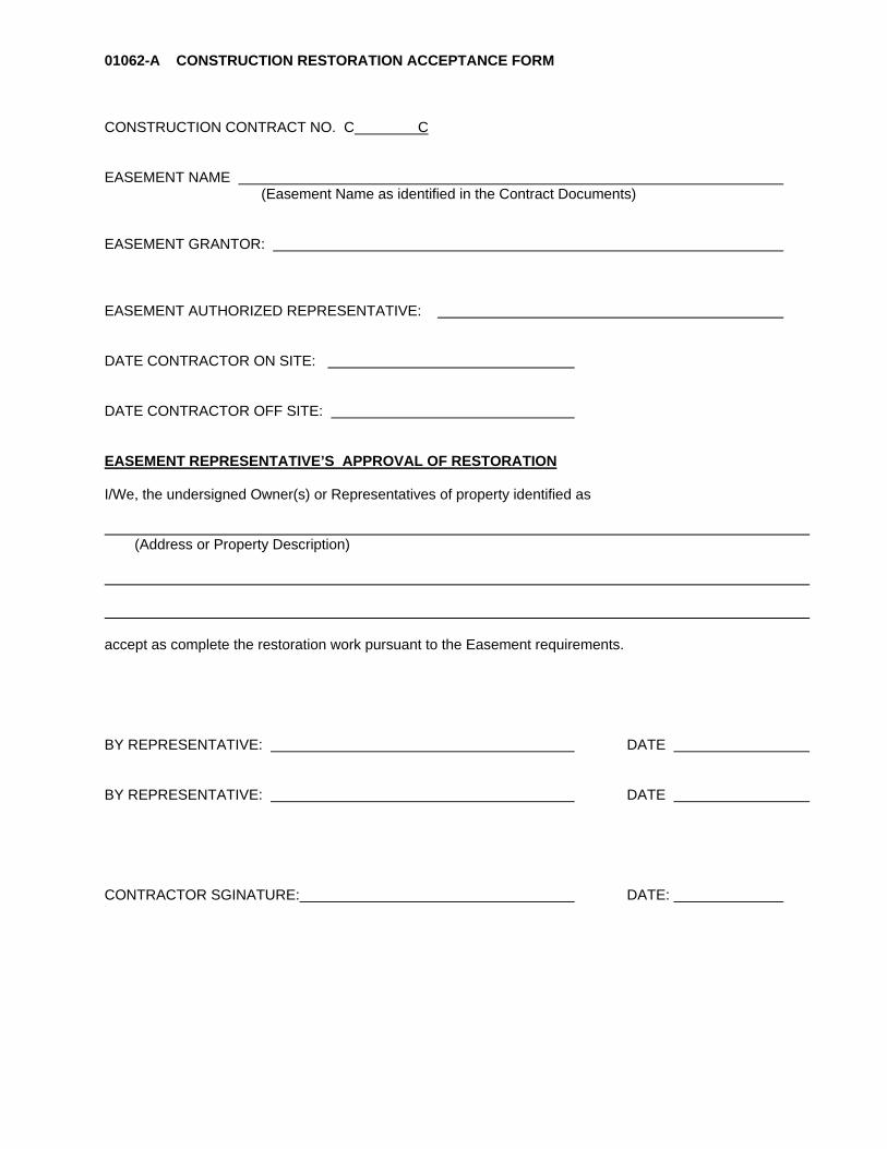
01062-A CONSTRUCTION RESTORATION ACCEPTANCE FORM CONSTRUCTION CONTRACT NO. C C EASEMENT NAME (Easement Name as identified in the Contract Documents) EASEMENT GRANTOR: EASEMENT AUTHORIZED REPRESENTATIVE: DATE CONTRACTOR ON SITE: DATE CONTRACTOR OFF SITE: EASEMENT REPRESENTATIVE’S APPROVAL OF RESTORATION I/We, the undersigned Owner(s) or Representatives of property identified as (Address or Property Description) accept as complete the restoration work pursuant to the Easement requirements. BY REPRESENTATIVE: DATE BY REPRESENTATIVE: DATE CONTRACTOR SGINATURE: DATE:

This page intentionally left blank.

01063-A MONTHLY CONTRACTOR INJURY SUMMARY REPORT Contract Name: Contract No: Month: Contractor: OSHA RECORDABLE CASES
WORK GROUP
NUMBER OF CASES Reporting Month Year-to-Date
Hourly Employees
Supervisory Personnel
TOTAL
LOST TIME ACCIDENTS
WORK GROUP
NUMBER OF CASES LOST WORKDAYS Reporting Month Year-to-Date Reporting Month Year-to-Date
Hourly Employees
Supervisory Personnel
TOTAL
TOTAL HOURS WORKED AT CONTRACT SITE
Reporting Month
Year-to-Date
INCIDENT AND SEVERITY RATE
Date of last lost-time accident:
Number of hours worked since last lost-time accident: Incident Rate =
Total Number of OSHA Recordable Cases x 200,000 Total Hours Worked at King County Project Site
Severity Rate = Total Number of Lost Workdays x 200,000
Total Hours Worked at King County Project Site
RATES Reporting Month Year-to-Date Incident Rate
Severity Rate
Monthly Incident Summary
DATE NAME TRADE COMPANY INCIDENT Contributors and
Preventive Measures

This page intentionally left blank.

Submittal Transmittal Form 01300-A
Contract Number: C_________C Submittal No. ___________KING COUNTY Date ___________WASTEWATERTREATMENT DIVISION Is this a Resubmittal? YES NO
If resubmittal, prior submittal number ___________
Does submittal contain deviations from the specifications YES NO
Does submittal contain sustainability requirements YES NOCONTRACTOR _________________________________________
Subcontractor or Supplier: _____________________________This Section to Be
Completed By King County
Item No. P/C Spec. ParagraphContractor's Cat. or Dwg.
No. Description of ItemCopies Submit
Review Action
Contractor Deviation
Contractor certifies to review of submittal, verification of Legend-Review Action Distribution: By (Print) Datefield measurements, and compliance with Contract Initial Review CompletedDocument unless noted otherwise in the submittal.
By: Date:
Reviewer Remarks
Project RepresentativeReturned To Contractor
Date Stamp
1 No exceptions taken2 Note Markings3 Comments Attached- Confirm4 Comments Attached- Resubmit5 Rejected
P - PartialC- Complete

Submittal Transmittal Form 01300-A - PAGE 2
Project Representative Review Routing Initial Date
No Exceptions Taken
Note Markings
Comments Attached-Confirm
Comments Attached-Resubmit
Rejected
Response Required of Contractor Construction Division Use OnlyReviewed Copies To: DateConstr. Division FilesProject RepresentativeContractor Proj. Eng.
Project Representative's review is for general conformance with the Contract. Markings or comments not specifically addressed in writing by the Contractor and accepted by the Project Representative in writing, shall not relieve the Contractor from compliance with the Contract. The Contractor remains responsible for details and accuracy, for confirming and correlating all quantities and dimensions, for selecting fabrication processes, for techniques of assembly and for performing its work in a safe manner.
Confirm Resubmit

FORM 01300-B SUBSTITUTION REQUEST FORM PAGE 1 OF 2 TO: ___________________________________________________________ CONTRACT NO. C_________C: CONTRACT NAME: We hereby submit for your consideration the following item instead of the specified item or procedure: Section Paragraph Specified Item ________ Proposed Substitution: Attach complete data, including laboratory tests, if applicable. Include complete information on changes to Contract Drawings and/or Specifications which proposed substitution would require for its proper installation. Fill in blanks below:
A. How will substitution affect dimensions shown on Drawings? _____________________________________________________________________ ____________________________________________________________________
B. What effect does the substitution have on the Baseline or Update Schedule?
_____________________________________________________________________ _____________________________________________________________________
C. State quality and performance differences between proposed substitution and specified item or procedure.
_____________________________________________________________________ _____________________________________________________________________ _____________________________________________________________________
D. List the cost differences between proposed substitution and specified item or procedure. (Attach estimate/quote and indicate net change).
_____________________________________________________________________ _____________________________________________________________________

FORM 01300-B SUBSTITUTION REQUEST FORM PAGE 2 OF 2
E. List manufacturer's name and address, trade name of product, and model or catalog number.
_____________________________________________________________________ _____________________________________________________________________ ____________________________________________________________________ F. Other information as required by the Project Representative. _____________________________________________________________________ _____________________________________________________________________ _____________________________________________________________________
G. The undersigned states that the function, appearance and quality of the proposed substitution are equivalent or superior to those of the specified item and authorizes the payment to the County for all design changes including Project Representative, detailing, and County processing costs.
_____________________________________________________________________ _____________________________________________________________________ H. The undersigned states that there is a waiver of all claims for additional costs related to the
substitution which may subsequently arise during the work. _____________________________________________________________________
I. Manufacturer's guarantees the proposed and specified items are:
_______ Same ______ Different (explain on attachment) Submitted by: For use by Project Representative
_______________________________ ____ Accepted ____ Accepted as Noted Contractor Signature
____ Not Accepted ____ Received Too Late ________________________________ Firm
By: ________________________________ Address Date:
________________________________ Remarks:
Date: ________ NOTE: WHEN REQUIRED BY THE PROJECT REPRESENTATIVE, ALL SUBSTITUTIONS
TO BE STAMPED AND SIGNED BY A PROFESSIONAL ENGINEER LICENSED IN THE STATE OF WASHINGTON.

Form 01350-A Recycled Content Materials Contract Name/No. ______________________________________________________________________________ Date __________________________ I, _______________________________________________, from ____________________________________________ verify the information provided below (Responsible Individual) (Company Name) is accurate to the best of my knowledge.
This project uses materials with recycled content so that at least 5% of the total weight of materials used in the project is from reclaimed or recycled materials.
Total weight of construction materials (exclude plants and soils and mechanical, electrical, and water equipment and their components)
Product Name/ Specification Section Manufacturer Product
Weight (lb)
Recycled Content %
Recycled Content
Weight (lb) Recycled Content Information Source Submittal No.
ex. Concrete/03300 Cadman Inc 1,000 10% 100 Cadman
Subtotal - Recycled Content Material Weight
Project % Recycled Content (Recycled content weight/total material weight)

This page intentionally left blank.
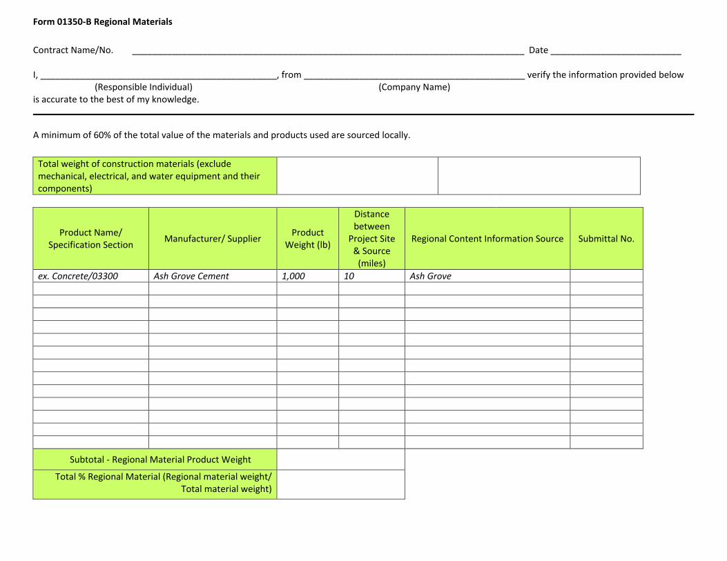
Form 01350-B Regional Materials Contract Name/No. ______________________________________________________________________________ Date __________________________ I, _______________________________________________, from ____________________________________________ verify the information provided below (Responsible Individual) (Company Name) is accurate to the best of my knowledge.
A minimum of 60% of the total value of the materials and products used are sourced locally.
Total weight of construction materials (exclude mechanical, electrical, and water equipment and their components)
Product Name/ Specification Section Manufacturer/ Supplier Product
Weight (lb)
Distance between
Project Site & Source
(miles)
Regional Content Information Source Submittal No.
ex. Concrete/03300 Ash Grove Cement 1,000 10 Ash Grove
Subtotal - Regional Material Product Weight
Total % Regional Material (Regional material weight/ Total material weight)

This page intentionally left blank.
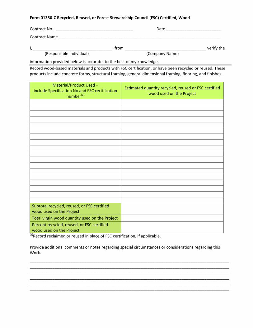
Form 01350-C Recycled, Reused, or Forest Stewardship Council (FSC) Certified, Wood Contract No. __________________________________ Date ________________________
Contract Name _______________________________________________________________________ I, ___________________________________, from ____________________________________ verify the (Responsible Individual) (Company Name)
information provided below is accurate, to the best of my knowledge. Record wood-based materials and products with FSC certification, or have been recycled or reused. These products include concrete forms, structural framing, general dimensional framing, flooring, and finishes.
Material/Product Used – include Specification No and FSC certification
number(1)
Estimated quantity recycled, reused or FSC certified wood used on the Project
Subtotal recycled, reused, or FSC certified wood used on the Project
Total virgin wood quantity used on the Project
Percent recycled, reused, or FSC certified wood used on the Project
(1)Record reclaimed or reused in place of FSC certification, if applicable. Provide additional comments or notes regarding special circumstances or considerations regarding this Work.
________________________________________________________________________________________________________________________________________________________________________________________________________________________________________________________________________________________________________________________________________________________________________________________________________________________________________________________ ________________________________________________________________________________________

This page intentionally left blank.

Form 01560-A
Page 1 of 4
Form 01560-A Environmental Mitigation Plan
Project No.: Project Name: Contractor: Date: Complete the following checklist. Use Section 01560, Section 02270, and Section 02271 as reference in preparing the Environmental Mitigation Plan. In the event the Environmental Mitigation Plan is determined at any time to be inadequate to protect the environment as determined by the Project Representative or any regulatory agency of jurisdiction, then the plan shall be modified to meet needed requirements. Provide answers in the blank boxes on the right. The box will expand if longer than box. Please be specific with answers that reflect the environmental construction practices of your firm; do not copy the language from the specifications. Partial sentences are acceptable.
Checklist Enforcement of Environmental Controls Name and phone number of person responsible for enforcement of environmental controls (24-hour contact).
Site Maintenance What types of contract construction materials will be stored on site?
Where and how long will wastes be stored on site before disposal?
Where will wastes, including hazardous wastes, be disposed? (Give name and location of landfills, etc.)
Waste Disposal Identify the waste product Estimated Volume Disposal Site
Street Cleaning How will dust and dirt on streets be controlled?
What methods will be used to eliminate transport of mud and dirt onto public roads by motor vehicles leaving the site?

Form 01560-A (continued)
Page 2 of 4
Air Pollution Control What measures will be taken by the Contractor to ensure that vehicles do not emit excessive pollutants to the air?
How will vehicles be maintained? How will dust on the construction site be controlled?
Noise Pollution Control What hours will construction occur? Where will air exchange fans/motors be located? How will you shield these from the residential areas?
Are all internal combustion engines to be used on this Contract equipped with mufflers as required in the specifications (Section 01560)?
The Contract specifications limit noise emissions. What activities do you expect to exceed these limits so that sound barriers will be required to meet the specifications?
What other methods do you propose to use to control noise emissions (if necessary)?
Water Quality Protection How will water from construction activities be treated and routed?
What materials will be used to prevent erosion and sedimentation of surface waters?
What other measures (besides placement of materials) are proposed for erosion control?
What is your schedule for installation of temporary erosion control structures? Permanent erosion control structures?
What is your schedule for inspection and repair of erosion control structures?
How will catch basins and storm drains be protected from sedimentation?
How will catch basin protection structures be maintained? What is your maintenance schedule?
What materials will be used to cover exposed soils under rainy or other adverse conditions?
How will you prevent concrete and wash down residuals from reaching surface waters and storm drains? Where will concrete trucks be washed?
Where will fueling of equipment take place? List specific spill sources (i.e., construction chemicals to be stored on site).

Form 01560-A (continued)
Page 3 of 4
How will oil and other construction chemicals be prevented from reaching surface waters (e.g., will barriers be placed around fueling areas to prevent the spread of accidental spills)?
Describe the materials and facilities to be maintained on the work site to prevent and clean up spills.
Where will spill prevention and clean up materials be stored?
How will accidental spills on land be contained and cleaned up?
How will accidental spills in water be contained and cleaned up?
What is your plan for training employees on spill prevention and control?
Where will oil wastes be disposed? What is your water quality monitoring plan (if required by the Department of Ecology Short Term Modification permit?
Traffic Control How will park trails be modified during construction?
What special signage, flagging, etc. will be placed in the park to inform park users of changes in park trails?
How will trucks enter and leave the park? Will any vehicles be required to cross the park trails? If so when?
When will removal of materials or deliveries occur during the day/night?
Will flaggers be required? If so, at what times of the day or night
Worker Protection What measures will be implemented to alert and protect workers from potentially contaminated soils and groundwater in construction excavations?
Historic Structures Protection What protective measures will be utilized when constructing near identified historic structures?
Cultural Resources Protection What protective measures will be utilized if cultural resources are encountered during construction?

Form 01560-A (continued)
Page 4 of 4
Site Plan Submit a site plan or plans, which will be implemented on site. The submittal may consist of existing plans. Include the following on plan or plans: ♦ Staging areas showing areas of chemical storage, spoils storage, and spill response equipment. ♦ Traffic ingress and egress. ♦ Pedestrian safety routes. ♦ Show locations of flaggers, if required. ♦ All waterways, drainage ditches, and storm drains identified for protection. ♦ Existing and final contours. ♦ Critical erosion areas. ♦ Existing drainage patterns. ♦ Limits of clearing and grading. ♦ Cut and fill slopes. ♦ Locations and details of erosion, sedimentation and stormwater control BMPs, including construction
entrances and exits. ♦ Conveyance details including locations of:
◊ grass-lined swales. ◊ interceptor trenches/ditches. ◊ sediment ponds/traps. ◊ drainage pipes. ◊ ditches or cut-off trenches associated with erosion and sediment control. ◊ outlets of any possible dewatering systems.
Add items as appropriate for the Contract.

DIVISION 02 SITE CONSTRUCTION

This page left intentionally blank.
August 2017 C01072C17 Georgetown Wet Weather Treatment Station 02045 - 1 CUTTING AND PATCHING
SECTION 02045
CUTTING AND PATCHING
PART 1 GENERAL
1.01 SUMMARY
A. This Section includes the requirements and limitations for cutting and patching of work.
1.02 QUALITY ASSURANCE (NOT USED)
1.03 SUBMITTALS
A. Procedures: Section 01300.
B. Submit written request in advance of cutting or altering elements which affects the following: 1. Structural integrity of the element. 2. Integrity of weather exposed or moisture-resistant elements. 3. Visual qualities of elements exposed to sight. 4. Operations of the facility.
1.04 CUTTING AND PATCHING
A. Employ skilled and experienced installer to perform cutting and patching work.
PART 2 PRODUCTS (NOT USED)
PART 3 EXECUTION
3.01 GENERAL
A. Execute cutting, fitting, and patching to complete the work and to: 1. Fit several parts together, to integrate with other work. 2. Provide openings in elements of work for penetrations of mechanical and electrical work. 3. Restore existing surfaces exposed by removal of work. 4. Uncover work to install or replace ill-timed work. 5. Remove and replace defective and non-conforming work.
B. Execute work by methods which will avoid damage to other work, and provide proper surfaces to receive patching and finishing. Inspect all cut surfaces to ensure that no electrical conduits or other piping (air, water, etc.) has been cut during the cutting operation. Report any issues to the Project Representative immediately.
C. Cut rigid materials using masonry saw or core drill.
D. Restore work with new products in accordance with requirements of Contract documents.
E. Fit work tight to pipes, sleeves, ducts, conduit, and other penetrations through surfaces. Maintain integrity of wall, ceiling, or floor construction: completely seal voids.

August 2017 C01072C17 Georgetown Wet Weather Treatment Station 02045 - 2 CUTTING AND PATCHING
F. Refinish surfaces to match adjacent finishes. For continuous surfaces, refinish to the nearest intersection; for an assembly, refinish the entire unit.
END OF SECTION

August 2017 C01072C17 Georgetown Wet Weather Treatment Station 02050 - 1 DEMOLITION AND DISPOSAL
SECTION 02050
DEMOLITION AND DISPOSAL
PART 1 GENERAL
1.01 SUMMARY
A. This Section specifies demolition and disposal of existing structures for the following reasons:
1. Structures or debris that shall be removed as part of normal work operations or encountered during construction of the elements identified on Drawings.
2. Structures, pilings, pipe, or debris that shall be removed to meet obligations with various permitting agencies. These structures and debris that are to be removed and disposed of are identified on the Drawings.
3. Remove and dispose of surplus or unsuitable excavated materials not required for project completion.
1.02 QUALITY ASSURANCE
A. Referenced Standards: This Section incorporates by reference the latest revision of the following documents. These references are part of this Section as specified and modified. In case of conflict between the requirements of this Section and those of the listed documents, the requirements of his Section shall prevail. Reference Title EPA, CFR, Title 49 Parts 171-179 Department of Transportation Hazardous Materials
Transportation Washington State Department of Dangerous Waste Regulations Ecology Title: WAC 173-303 Ecology Title: WAC 173-350 Solid Waste Handling Standards
B. Qualifications: 1. Documentation of experience: a. Certifications, permits and/or licenses as required by Federal, State or local authorities and
their expiration date.) 2. Personnel taking and managing samples shall have the necessary training and have a minimum
of 1-year experience in environmental sampling.
3. Analytical laboratory: accredited in accordance with Chapter 173-050 WAC.
1.03 SUBMITTALS
A. Procedures: Section 01300.
B. Schedule of Work planned.
C. Dredge and Fill Plan per Section 02323 with waste classification, handling and disposal requirements.
D. Construction Waste Management Plan per Section 01715
E. Environmental Management Plan per Section 01560
F. List of acceptable and approved waste disposal sites for items to be disposed.
August 2017 C01072C17 Georgetown Wet Weather Treatment Station 02050 - 2 DEMOLITION AND DISPOSAL
1.04 MATERIAL DISPOSITION, STORAGE AND HANDLING
A. Salvage Items: No items have been designated for salvage.
B. Reuse Items: No items have been designated for reuse.
C. Materials Demolition and Disposal: 1. Unless otherwise specified, materials removed become the property of the Contractor. These
items shall be removed from the Site and recycled or otherwise disposed of to meet the target landfill diversion rate (see Section 01715).
1.05 GENERAL REQUIREMENTS A. Comply with federal, state, and local and site-specific requirements applicable to the work, including demolition, removal, packaging, hauling, and disposal regulations.
1.06 JOB CONDITIONS
A. Protection: 1. Remove materials, structures, or debris in a manner that protects adjacent structures and utilities. 2. Repair or replace property that is damaged.
1.07 CONTRACTOR’S RESPONSIBILITIES
A. Should suspect material not identified in this Section be encountered, immediately suspend all work that could disturb said material and notify the Project Representative by voice and in writing, who will implement the proper action. Do not proceed with work that could disturb the material until authorized by the Project Representative in writing to do so.
1.08 COUNTY’S RESPONSIBILITIES
A. Upon notification by the Contractor of the existence of suspect material not identified in this Section, the Project Representative will have said material inspected and analyzed as appropriate.
B. If the results of the inspection confirm the presence of other dangerous, hazardous or regulated substances in the suspect material, the County will take the necessary actions for compliance with the State and Federal regulations. After compliance is obtained, the Project Representative will notify the Contractor in writing so that work under this Contract can proceed.
PART 2 PRODUCTS (NOT USED)
PART 3 EXECUTION
3.01 GENERAL
A. Site Access and Temporary Controls: Conduct demolition and disposal operations to ensure minimum interference with roads, streets, walks, walkways, and other adjacent occupied and used facilities.

August 2017 C01072C17 Georgetown Wet Weather Treatment Station 02050 - 3 DEMOLITION AND DISPOSAL
3.02 OPERATION PROCEDURES
A. Start and complete Work in order of precedence as established by the schedule. Operational procedures and sequence of Work is optional provided Work does not infringe upon or violate schedule or permit requirements.
B. Do not begin the Work covered under this Section until Dredge and Fill Plan per Section 02323 has been approved by the Project Representative.
C. Execute Work to protect County employees, County Representatives, waterway users, and the public from injury. Provide protection to persons and property. Conduct operations to ensure minimum interference with roads, piers, floats, ramps, and other adjacent occupied facilities.
D. Contractor is responsible for ensuring that suitable means of hauling material are provided with effective measures to prevent any material from being released during transport from the project site to the approved disposal facility.
3.03 PROTECTION
A. Environmental Protection: Manage demolition activities in accordance with the Plans specified above and in Section 01560, Environmental Management, 01570, Traffic Regulation and 01505 Construction Waste Management, as well as applicable federal, state and local regulation. Comply with Site-specific Environmental Protection controls to ensure the protection of the public, onsite workers, and the environment.
B. Protection of Personnel: 1. During demolition, continuously evaluate the condition of the structure being demolished and take
immediate action to protect all personnel working in and around the demolition site. 2. Provide temporary barricades and other forms of protection to protect Owner’s personnel and the
general public from injury due to demolition Work. 3. Provide protective measures as required to provide free and safe passage of Owner’s personnel
and the general public to occupied portions of the structure. 4. Provide suitable decontamination facilities for workers in accordance with all applicable federal
and state laws at a location specified by the Project Representative.
C. Burning: The use of burning at the Site for the disposal of refuse and debris will not be permit.
3.04 CUTTING AND REMOVAL OF RIVER BANK ARMORING MATERIALS AND SUNKEN DOCK
A. Neatly cut and remove materials and prepare openings to install trench sheeting, trestle piles, and receive new Work, in accordance with applicable permit requirements.
B. Cement grindings or cuttings shall be contained so that they do not enter the waterway.
C. Remove masonry or concrete in small sections.
D. Provide shoring, bracing, and other supports to prevent movement, settlement, or collapse of remaining or adjacent wall areas, structure, or facilities. Arrange shoring, bracing, and supports to prevent overloading of structure.
E. Take precautions necessary to prevent damage to existing remaining Work or to adjacent facilities. Execute Work using methods that will prevent interference with use of remaining and adjacent facilities by the County, WSDOT, utilities, or other public goods.

August 2017 C01072C17 Georgetown Wet Weather Treatment Station 02050 - 4 DEMOLITION AND DISPOSAL
F. To the maximum extent feasible, excavation and removal of existing bank materials shall be done while active work areas are above tide level.
G. No excavated material from below MHHW shall be reused as fill material.
3.05 CREOSOTE-TREATED TIMBER PILE REMOVAL
A. Follow all procedures in "Best Management Practices For Pile Removal & Disposal, dated March 1, 2007, which follows the end of this specification section as Attachment A. Notify Project Representative for direction if discrepancies are noted between this document and these project Specifications. Piles beneath and east of southbound SR 99/509 bridge are not accessible by crane and may be cut off below grade in accordance with BMP 1.B.
B. Also comply with all relevant provisions of the Hydraulic Project Approval. Notify Project Representative if there is any conflict between it and Attachment A.
C. Creosote-treated timber piles shall be separated from other construction debris and stored at a designated contained storage area. Storage area and procedures shall be approved by the Project Representative.
D. The Contractor shall obtain all permits and disposal approvals required to dispose of creosote-treated timber piles prior to removal of the piles.
E. Sampling, testing, reporting, disposal, and other related activities are regulated by disposal permit obtained by approved disposal site.
3.06 EXCAVATED NATIVE MATERIAL
A. The Contractor shall be responsible for legal disposal of all surplus excavated native materials.
3.07 CLEANUP
A. Remove debris, rubbish and materials resulting from cutting, demolition or patching operations. Do not remove materials prior to approval of Construction Waste Management Plan and Dredge and Fill Plan by the Project Representative.
B. Transport materials and legally dispose of off-site.
C. Do not discharge any materials to sanitary sewer, storm drain, or water way, except as specifically identified in the Site permits.
D. The Contractor shall be responsible for onsite waste management and packaging, and for coordinating the offsite waste transportation and disposal.
3.08 WASTE DISPOSAL SITE
A. Waste disposal sites shall be secured by the Contractor and shall be operated in accordance with all federal, state and local codes, permits and ordinances. Sites, operations, or results of such operations, which create a nuisance problem, or which result in damage to public or private properties shall not be permitted.

August 2017 C01072C17 Georgetown Wet Weather Treatment Station 02050 - 5 DEMOLITION AND DISPOSAL
B. Disposal sites and their operation shall, at all times, be subject to the Project Representative’s approval. No disposal site shall be utilized by the Contractor until the proper permits, disposal approval, and/or property owner agreements have been obtained by the Contractor and copies submitted to the Project Representative. Sites utilized by the Contractor without the proper permits, property owner agreement, and approvals of the Project Representative shall be considered unauthorized.
C. Record of the number of truckloads and quantities of excavated soils, debris and/or timber piles unloaded at each and every disposal site. Provide Project Representative documentation of truckloads and quantities for each load.
D. Upon completion of the Work and before final acceptance and payment, the Contractor shall clean up all waste disposal sites on which the Contractor has operated.
E. Upon completion of grading operations at any waste disposal site for which a written agreement between the Contractor and property owner is required, the Contractor shall obtain and furnish to the Project Representative, a release from all damages, duly executed by the property owner, stating that the restoration of the property has been satisfactorily accomplished. Retainage withheld from the Contractor’s payments shall not be released until all such property owner releases have been furnished to the Project Representative. Should the release be, in the opinion of the Project Representative, arbitrarily withheld, then the Project Representative may, of its sole discretion, accept that portion of the Work involved and cause final payment to be made.
F. All costs and expenses involved in securing, operating and maintaining any waste disposal site (including final cleanup and any erosion or anti-pollution controls required in the permits, property owner agreements, grading regulations, and other contract requirements) shall be considered as incidental to the Contract and such costs and expenses shall be included in the price bid for the Work. No separate payment shall be made.
END OF SECTION

August 2017 C01072C17 Georgetown Wet Weather Treatment Station 02050 - 6 DEMOLITION AND DISPOSAL
This page intentionally left blank.

August 2017 C01072C17 Georgetown Wet Weather Treatment Station 02050 - 7 DEMOLITION AND DISPOSAL
ATTACHMENT A
BEST MANAGEMENT PRACTICES FOR PILE REMOVAL AND DISPOSAL

August 2017 C01072C17 Georgetown Wet Weather Treatment Station 02050 - 8 DEMOLITION AND DISPOSAL
This page intentionally left blank.

Best Management Practices
For Pile Removal & Disposal
March 1, 2007
The purpose of the following Best Management Practices (BMPs) is to control turbidity and sediments re-entering the water column during pile removal, and prescribe debris capture and disposal of removed piles and debris. BMP 1. Pile removal
A. Vibratory extraction is the preferred method of pile removal.
1) Crane operator shall be trained to remove pile slowly. This will minimize turbidity in the water column as well as sediment disturbance.
2) Operator to “Wake up” pile to break up bond with sediment.
Vibrate to break the skin friction bond between pile and soil. Bond breaking avoids pulling out a large block of soil – possibly
breaking off the pile in the process. Usually there is little or no sediment attached to the skin of the pile
during withdrawal. In some cases material may be attached to the pile tip, in line with the pile.
3) A major creosote release to the environment may occur if equipment
(bucket, steel cable, vibratory hammer) pinches the creosoted piling below the water line. Therefore, the extraction equipment must be kept out of the water.
4) Piling must not be broken off intentionally by twisting, bending or
other deformation. This practice has the potential for releasing creosote to the water column.
5) Work surface on barge deck or pier shall include a containment basin
for pile and any sediment removed during pulling.
6) Basin may be constructed of durable plastic sheeting with sidewalls supported by hay bales or support structure to contain all sediment. Water run off can return to the waterway.
7) Work surface shall be cleaned by disposing of sediment or other
residues along with cut-off piling as described in BMP 2C below.
8) Containment basin shall be removed and disposed in accordance with BMP 2C below or in another manner complying with applicable federal and state regulations.
1

9) Upon removal from substrate the pile shall be moved expeditiously
from the water into the containment basin. The pile shall not be shaken, hosed-off, stripped or scraped off, left hanging to drip or any other action intended to clean or remove adhering material from the pile.
B. Cutting will be necessary if the pile has broken off at or near the existing
substrate so that it cannot be removed without excavation, or below the water line. Pile cutoff is an acceptable alternative if vibratory extraction or pulling is not feasible. Every attempt should be made, however, to completely remove the piling in its entirety before cutting. If a pile is broken or breaks above the mudline during vibratory extraction, one of the methods listed below should be used to cut the pile. Prior to commencement of the work the project engineer or contractor should assess the condition of the pilings. Contractor or project engineers need to create a log outlining the location and number of pilings that need to be cut and have this log available to the agencies upon request.
1) A chain should be used, if practical, to attempt to entirely remove the
broken pile. 2) If the entire pile cannot be removed, the pile should be cut at or below
the mudline by using a pneumatic underwater chainsaw. Project-specific requirements for cutoff should be set by the project engineer considering the mudline elevation and the presence of contaminants in the sediment. Generally, piling should be cut off at the mudline if sediments are contaminated and the mudline is subtidal, to minimize disturbance of the sediment. Piling should be cut off at least 1 foot below the mudline in intertidal areas where the work can be accomplished in the dry. Piling should be cut off at least 1 foot below the mudline in subtidal areas where the sediments are not contaminated. Repeated attempts to remove pile with a clamshell bucket (i.e., “grubbing”) should not occur in contaminated sediments, or below the water line.
3) Piles shall be cut off at lowest practical tide condition and at slack
water. This is intended to reduce turbidity due to reduced flow and short water column through which pile must be withdrawn.
4) If the piling is broken off below mudline greater than 1 foot, the piling
may remain, provided it is located in deep subtidal waters. In intertidal and shallow subtidal areas, seasonal raising and lowering of the beach could expose the pilings above the mudline and leach out PAHs or other contaminants. In this case, the piling should be cut off at least two feet below the mudline if it is accidentally broken off during removal.
2

5) Depending on future use, the removal contractor should provide the location of the broken pile using GPS. This will be necessary as part of debris characterization should future dredging be a possibility in the area of piling removal.
BMP 2. Disposal of piling, sediment and construction residue
A. Pulled pile shall be placed in a containment basin to capture any adhering sediment. This should be done immediately after the pile is initially removed from the water.
1) Utilize basin set up on the barge deck or adjacent pier
2) Basin may be made of hay bales and durable plastic sheeting.
B. Piling shall be cut into 4’ lengths with standard chainsaw.
C. Cut-up piling, sediments, construction residue and plastic sheeting from the
containment basin shall be packed into a container. For disposal, ship to Rabanco/Seattle, Weyco facility at Longview Washington, or to another facility complying with federal and state regulations.
BMP 3. Pile replacement
A. Pile material
1) EPA prefers concrete piles for large structural replacements. Pilings made up of painted steel, unpainted steel, steel coated with epoxy-petroleum compound or plastic are also acceptable. Should untreated wood be used for fender piles then rub strips are recommended on the face of the wood.
2) ACZA treated timber piles may be used that comply with the Amendment
to the Best Management Practices for the Use of Treated Wood in Aquatic Environments; USA Version – Revised April 17, 2002. Western Wood Preservers Institute. Rub strips are recommended if ACZA treated wood is to be used for fender piles. Coordination with WDFW is also recommended regarding metal leachability into the aquatic environment. When using ACZA, it is recommended that it be demonstrated that copper and arsenic levels in surrounding sediments be within the state SQS.
B. Vibratory hammer shall be used to drive piles. Work may be done from
floating or land based construction equipment.
BMP 4. Debris capture in water
A. Floating surface boom shall be installed to capture floating surface debris. Debris is to be collected and disposed of along with cut-off piling as described in BMP 2C above.
3

4
BMP 5. Resuspension/Turbidity
A. Crane operator shall be trained to remove pile from sediment slowly.
B. Work shall be done in low water and low current.
C. Removed piles shall be placed in a containment facility.
D. Sediments spilled on work surfaces shall be contained and disposed of with the pile debris at permitted upland disposal site.

August 2017 C01072C17 CONTAMINATED SOIL AND SEDIMENT Georgetown Wet Weather Treatment Station 02060 - 1 HANDLING AND DISPOSAL
SECTION 02060
CONTAMINATED SOIL AND SEDIMENT HANDLING AND DISPOSAL
PART 1 GENERAL
1.01 SUMMARY
A. This Section specifies excavating, screening, handling, stockpiling, sampling, analysis, and disposing of contaminated soils and sediments that are known, that may be encountered, or are Contractor-generated during the Work. This section covers both soils excavated from upland areas and sediments excavated from the Duwamish Waterway.
1.02 QUALITY ASSURANCE
A. Referenced Standards: This Section incorporates by reference the latest revision of the following documents. These references are part of this Section as specified and modified. In case of conflict between the requirements of this Section and those of the listed documents, the requirements of this Section shall prevail. Reference Title 29 CFR 1910 Occupational Safety and Health Standards (OSHA) 40 CFR 262 Subpart D Recordkeeping and Reporting Chapter 173-50 WAC Accreditation of Environmental Laboratories Chapter 173-303 WAC Dangerous Waste Regulations Chapter 296-62 WAC General Occupational Health Standards Chapter 173-340 WAC Model Toxics Control Act (MTCA) Cleanup Regulations Chapter 173-350 WAC Solid Waste Handling Standards Ecology Pub. No. 10-09-057 Guidance for Remediation of Petroleum Contaminated Sites Ecology Pub. 94-115 Natural Background Soil Metals Concentrations in Washington
State Chapter 171-178 Department of Transportation (DOT)
B. Qualifications: 1. Personnel assigned for the purpose of performing or supervising contaminated soil work shall
have received appropriate safety training in compliance with OSHA standard 29 CFR 1910.120 and 29 CFR 1910.134 and Chapter 296-62 WAC. a. Minimum of 40 hours of HAZWOPER training. b. 24 hours of “on the job” training. c. Eight hours annual refresher training and annual medical monitoring by an occupational
physician is required. d. Minimum of eight hours additional specialized training in managing contaminated soil
operations is required for supervisory personnel. 2. Personnel taking and managing samples shall have the necessary training and have a minimum
of 1-year experience in environmental sampling. 3. Analytical laboratory: accredited in accordance with Chapter 173-050 WAC. 4. Documentation of Experience:
a. Certifications, permits and/or licenses as required by Federal, State or local authoriies and their expiration date.
b. Waste Transporter: Documentation of licensing and equipment capabilities with trucks equipped with containment and cover systems to transport solid and liquid waste materials on public streets and roads without spillage.
c. Offsite Disposal and/or Treatment Facilities: Documentation of permitting, disposal requirements, and acceptance of waste.

August 2017 C01072C17 CONTAMINATED SOIL AND SEDIMENT Georgetown Wet Weather Treatment Station 02060 - 2 HANDLING AND DISPOSAL
1.03 SUBMITTALS
A. Procedures: Section 01300.
B. Qualifications.
C. Contaminated Soil and Sediment Handling (CSH) Plan.
D. Certification of the selected disposal site(s) prior to any offsite transport of soil or sediment.
E. Evidence that a state-licensed transporter shall be used.
F. Analytical testing reports and figures of sampling locations.
G. Disposal documentation.
H. Daily inventory of stockpiles or containers holding waste.
1.04 DEFINITIONS
A. Contaminated Soil and Sediment: Soil or sediment containing contaminant concentrations in excess of MTCA, Dangerous Waste Regulations, Solid Waste Handling regulations, natural background as defined by Ecology Publication No. 94-115 or other regulatory criteria.
B. Excavated Soil and Sediment: Soil or sediment removed for this work. Soil is defined as originating from upland areas. Sediment is defined as soil from all areas covered by water, including intertidal area.
C. Dangerous Waste: Any liquid, solid, gas or sludge that exhibits any of the physical, chemical, or biological properties described in WAC 173-303-090 or 173-303-100.
D. Suspect Material: Material in the excavation which is potentially contaminated or impacted based on visual observation and odor; includes soil or foreign material found with the excavation limits.
E. Uncontaminated Soil and Sediment: Soil that is odor free, has no detectable levels of contaminants (for metals contaminants – has no detectable levels of contaminants above natural background as defined by Ecology Publication No. 94-115) and meets Category 1 Soils, as defined by Ecology Publication No. 10-09-057.
1.05 GENERAL REQUIREMENTS
A. During construction, contaminated soil and sediment will be encountered. Work requires management and disposal of contaminated soil and sediment generated to complete the work. Reference and coordinate CSH Plan with activities described in Section 02200, 02270,02271 and 02323.
B. Notify the Project Representative immediately if contaminated substances are discovered which had not been previously identified or if other discrepancies between data provided and actual field conditions are discovered.
C. During excavation work, the Contractor shall have on site personnel trained in identifying potential soil contamination using visual and olfactory observations, and field instrumentation.
D. Conduct work in accordance with the CSH Plan and applicable federal, state, and local statutes, regulations, and standards. Coordinate CSH Plan with Dredging and Fill Plan (Section 02323).

August 2017 C01072C17 CONTAMINATED SOIL AND SEDIMENT Georgetown Wet Weather Treatment Station 02060 - 3 HANDLING AND DISPOSAL
E. Be responsible for the excavation, stockpiling, sampling, testing, and disposal of soil and sediment.
F. There is a potential to encounter water in the soil excavations due to the estimated depth to groundwater. Reference Dewatering (section 02140) and Site Water Discharge (section 02271) for this condition.
G. Dewatering water from contaminated soil and sediment activities shall be handled per Section 02271,’
1.06 CONTAMINATED SOIL AND SEDIMENT HANDLING (CSH) PLAN
A. Detailed plan outlining the procedures for excavation, screening, identification, stockpiling, sampling, testing, and disposal of Contaminated Soil and sediment. l.
B. At a minimum, the CSH Plan shall include: 1. Schedule of activities. 2. Methods and procedures of excavation and equipment and personnel to be used including
proposed means of containment during excavation and transfer of contaminated soil to prevent releases
3. Shoring or side-wall slopes proposed. 4. Staging and storage methods, procedures, and proposed locations, sizes and physical area to be
used for stockpiling of contaminated soil and sediment. Identify procedures for covering stockpiles to prevent dispersion from rain or wind prior to transport. Identify methods to provide barriers so staging and stockpiling areas are not easily accessible to the public.
5. If barge-based options are used for removal of contaminated sediments provide information on handling of barge dewatering water and barge offsite transloading procedures and location
6. Haul routes. 7. Methods, procedures, and proposed documentation for the transportation and disposal of
contaminated soil and sediment including the identification of disposal facilities and licensed transporters. Identify measures to prevent any material from being released during transport from the project site to the approved disposal facility.
8. Decontamination procedures and measures that will be implemented to minimize the risk of exposure to contaminated soil, sediments, or groundwater.
9. Sampling and analysis plan that covers Contractor sampling and testing responsibilities and disposal designation procedures.
10. Best Management Practices (BMPs) to ensure safe handling, storage, and transport of contaminated or potentially contaminated soil, sediments and substrate (e.g., spill aprons, drop curtains, gated hoppers operating from fixed locations, sealed containers, etc.).
1.07 SITE CONDITIONS
A. Contaminated soil and sediment is present within the limits of the work.
B. Data from environmental sampling and analysis completed for the project are contained in the GDR. 1. Soil contains diesel-, oil- and residual-range petroleum hydrocarbons, volatile constituents and
metals. 2. Sediment contains metals, and PAHs . 3. Other potentially hazardous chemicals may be present. Contractor is to comply with all Federal,
State and local regulations for worker protection and health and safety and as specified in Section 01001, Health and Safety Requirements.
C. None of the contaminated soil or sedimentis expected to designate as astate of Washington Dangerous Waste based on data presented in Section 01036. If contaminated soil or sediment designates as a Dangerous Waste, it will be removed from the stockpile and placed in containers and removed from the site for offsite disposal in accordance with Chapter 173-303 WAC

August 2017 C01072C17 CONTAMINATED SOIL AND SEDIMENT Georgetown Wet Weather Treatment Station 02060 - 4 HANDLING AND DISPOSAL
PART 2 PRODUCTS
2.01 GEOMEMBRANE BOTTOM LINER
A. Stockpile geomembrane liner material shall be minimum 30 mil, impermeable impermeable liner of sufficient strength and thickness to prevent puncture during use. Each side of the impermeable liner will be protected with nonwoven geotextile fabric. The placement of soil into the stockpile area will not involve any equipment or procedures that may jeopardize the integrity of the underlying impermeable liner. All seams shall be taped or weighted down full length. All seams shall have a minimum 12 inches overlap..
2.02 GEOMEMBRANE COVER
A. Shall be 10 mil, reinforced polyethylene, impermeable and resistant to long-term (two years) ultraviolet radiation, weathering, and degradation due to contact with Contaminated Soils. It shall be free from holes, oil, foreign matter, scathes, cracks, bubbles, undispersed raw materials, and blisters. Install in single thickness parallel to the direction of drainage. Maintain cover tightly in place by using sand bags on ropes with a maximum 10-foot grid spacing in all directions. Overlap seams at least 12 inches. The cover will be in place except while soil is actively being placed or removed..
2.03 STRAW BALES
A. Tied with twine, with no excessive quantities of mature seed of noxious weed or other plant species.
2.04 SAND BAGS
A. Close knit, sunlight-resistant nylon or equivalent bags filled with clean sand and tied or fastened closed; suitable for frequent handling and all-season use.
2.05 MATERIALS
A. Trucks: Solid bulk trucks (end dump, tandem) in good condition, clean and without leaks. Trucks shall have back up alarm, automatic tarps in good condition, and lined beds.
B. Drying agent: To meet industry standards and be used if necessary if excavated soils require solidification prior to placing in trucks.
C. Truck Liners: To meet industry standard specifications, as a minimum.
D. Tarping Station: To be used if required. Personnel may not climb on trucks for lining or tarping of trucks.
PART 3 EXECUTION
3.01 CONTRACTOR’S RESPONSIBILITY
A. Personnel working with Suspect Material and Contaminated Soil and Sedimentl shall have received training and have experience for the work to be performed.
B. Identify areas and sizes for stockpiling based on the Contractor’s rate of production for the excavation, dewatering of sediments prior to transport offsite and the turnaround time for sampling and testing. Manage dewatering fluids per Section 02271. Manage demolition debris per Section 02050. If sediments are to be transloaded from a barge, identify locations and procedures.
C. Dispose of excavated soil and sediment. Follow protocols defined in Attachment A of this Section.
August 2017 C01072C17 CONTAMINATED SOIL AND SEDIMENT Georgetown Wet Weather Treatment Station 02060 - 5 HANDLING AND DISPOSAL
1. Excavate and screen soil and sediment. 2. Stockpile Suspect Material. 3. Sample and test stockpiled soil and sediment. 4. Designate soil and sediment for disposal on the basis of testing results. 5. Transport and dispose of soil and sediment in accordance with the requirements of this Section.
3.02 COUNTY’S RESPONSIBILITY
A. The County will sign as generator or owner of the Contaminated Soil and Sediment.
B. If soils or sediments are found to be Hazardous or Dangerous Wastes, the County will be responsible for additional costs associated with testing and disposal.
3.03 SOIL AND SEDIMENT FIELD SCREENING
A. Excavated soil shall be screened by the Project Representative for contamination in accordance with Ecology Pub. No. 10-09-057, Section 5.3 Field Screening.
3.04 STOCKPILING, SAMPLING, AND ANALYSIS
A. Suspect Material shall be stockpiled separate from other soils and sediments to allow for testing.
B. Stockpiling: 1. General Requirements:
a. Prevent intermixing of stockpiled materials with underlying soils. b. Prevent influx of rainwater. c. Prevent erosion of stockpiled materials. d. Apply stormwater BMPs as appropriate for stockpile construction and maintenance. e. Maintain daily inventory of stockpile areas and sizes and provide information to Project
Representative as requested. 2. Construction:
a. The stockpile shall be a contained system that may include ready-made structures or facilities to contain soil and liquids.
b. Construct stockpiles with geomembrane bottom liner over prepared subgrade and bedding material as recommended by manufacturer.
c. Provide retention berm around entire perimeter of stockpile consisting of hay bales or ecology blocks.
d. Overlay retention berm with bottom liner and secure liner to outside of berm. e. Place stockpiled material on bottom liner within retention berm. f. Place geomembrane cover over stockpiled material overlapping retention berm. g. Adequately secure cover with sand bags, or equivalent, at not less than 10-foot intervals
around entire perimeter of stockpile. 3. Operation and Maintenance:
a. Maintain a separate stockpile for each days generation of suspect material. b. Do not stockpile soils containing free flowing liquids. c. Prevent intermixing of contaminated and clean soils and water. d. Prevent damage to stockpile berms during in-loading and out-loading. e. Prevent formation of rainwater ponding on the surface of the cover. f. Collect and dispose of water that accumulates within bermed area per Section 02271. g. Segregate suspect material for disposal according to analytical results from sampling. h. Decontaminate excavation equipment after working with Contaminated Soil and Sediment.
C. Sampling by Contractor: 1. Notify Project Representative at least 4 hours prior to sampling of stockpiles. 2. Samples shall be collected at a frequency in accordance with Table 6.9 of Ecology Publication
No. 10-09-057.

August 2017 C01072C17 CONTAMINATED SOIL AND SEDIMENT Georgetown Wet Weather Treatment Station 02060 - 6 HANDLING AND DISPOSAL
3. Sample collection procedures shall be in accordance with Ecology and EPA requirements. 4. Project Representative shall be present during stockpile sampling. 5. Submit sketch of stockpile sampling locations at the end of each day of sampling.
D. Analysis: 1. General Requirements:
a. Samples of stockpiled soil shall be analyzed for the following contaminants: 1) Total Metals by EPA Method 6010/7471 (RCRA 8 metals plus copper, nickel and zinc) 2) Gasoline-range total petroleum hydrocarbons (TPH-G) by the Northwest Total Petroleum
Hydrocarbon Method (NWTPH). 3) Volatile organic compounds (VOCs) by EPA Method 8260. 4) Diesel-range extended total petroleum hydrocarbons (TPH-Dx) by NWTPH. 5) Polychlorinated biphenyls (PCBs) by EPA Method 8082. 6) Any additional analyses required by the Contractor-selected disposal facility.
b. Samples shall be analyzed on 48-hour turn-around times or as directed by Project Representative.
2. The analytical results of the soil samples shall be used to determine the waste designation of the soil (i.e. Contaminated Soil, I or Uncontaminated Soil).
3. Analytical results and proposed waste designation(s) shall be submitted to the Project Representative prior to disposal of Contaminated Soil and Sediment.
4. Contractor is responsible for selecting an appropriate permitted facility for offsite disposal and obtaining acceptance from that facility
5. Contractor will provide acceptance paperwork to Project Representative PRIOR to any offsite shipments of soil and sediment from the site.
6. Contractor will prepare all disposal paperwork, including waste profile forms, applicable example manifests and labels. The paperwork will be provided to the Project Representative a minimum of one (1) week prior to disposal for review and obtaining generator signature. Once the example manifest has been approved, Contractor will provide pre-printed manifests for transportation and disposal of all waste.
3.05 DISPOSITION OF TESTED SUSPECT MATERIALS, AND CONTAMINATED SOIL AND SEDIMENT
A. Provide labor, equipment, and materials to solidify or process waste materials as necessary to meet minimum requirements for offsite transport and disposal. NOTE – excavation will take place below water table in some areas of the Site. Contractor will be prepared to solidify soil as needed for load out and transportation. No soil will be loaded or shipped with free liquids nor arrive at the disposal facility with free liquids
B. Offsite Waste Disposal Facility Qualification - Contractor shall identify transportation and disposal facilities and provide information in the bid proposal. This information shall be provided to Project Representative for their approval of the facilities upon receiving the proposals. Once Contractor has submitted the information on transporters and the facilities, Subcontractor cannot deviate from the intended facilities submitted with their proposal, without Project Representative’s prior approval.
C. Offsite Disposal of Suspect Material, Contaminated Soil and Sediment 1. Provide transportation in accordance with Department of Transportation (DOT) Hazardous
Material Regulations and Federal, State, and local requirements, including obtaining necessary permits, licenses, and approvals.
2. Dispose at a RCRA Subtitle D landfill in accordance with applicable laws and regulations `and conditions specified herein.

August 2017 C01072C17 CONTAMINATED SOIL AND SEDIMENT Georgetown Wet Weather Treatment Station 02060 - 7 HANDLING AND DISPOSAL
3. Disposal Records: a. Records of waste determinations, including appropriate results of analyses performed,
substances and sample location, the time of collection, and other pertinent data in accordance with WAC 173-303-210 and 40 CFR 262 Subpart D, and other applicable regulations.
b. Transportation, disposal methods and dates, the quantities of waste, the names and addresses of each transporter and the disposal or reclamation facility, as well as copies of the following documents: 1) Manifests. 2) Waste analyses or waste profile sheets. 3) Certifications of final disposal signed by the responsible disposal facility official. 4) Records shall be provided in accordance with applicable Federal, State, and local
regulations. The records shall become the property of the County.
D. Transportation: 1. Provide lined vehicles and other measures necessary to prevent spillage of waste materials, mud,
or other debris on local streets or roads. 2. The Contractor will set-up a tarping station at the site where the drivers can safely line, untarp
and tarp truck beds without climbing on the truck (safety hazard). Individuals will not be allowed to climb on trucks to cover load. Means and methods of the tarping station will be detailed in the Contaminated Soil and Sediment Handling Plan.
3. Drivers will remain in their trucks at all times while onsite. The Contractor will provide personnel to tarp/untarp the trucks while on site so that the Driver does not need to leave the vehicle.
4. Inspect and document vehicles and containers for proper operation and covering. 5. Inspect vehicles and containers for proper markings, manifests, and other requirements for waste
shipment. 6. Perform and document decontamination procedures prior to leaving Site. 7. Obtain and submit receipts of confirmation from disposal or treatment facilities that wastes were
accepted for disposal or treatment, including weight tickets or other confirmation of quantities received.
8. The Transportation Subcontractor will dispatch bulk truck transportation in good condition (clean, no leaks, etc.) to the project site appropriate for transportation of nonhazardous waste. Soil trucks shall have liners, backup alarm, and automatic tarps which will also be in good condition (no tears/holes).
9. The Project Representative reserves the right to inspect and reject any container arriving on-site or leaving the site. The Transportation Subcontractor will incur all costs associated with truck rejection and truck transfer and replacement.
10. The transporter shall adhere by and be in compliance with all regulatory requirements under 49 CFR and any state requirements as applicable.
11. Every load of waste will be sent offsite using appropriate non-hazardous manifests and signed by the Project Representative. Project Representative MUST be aware of all shipments.
12. Any changes in transporters will be communicated to Project Representative before arrival at the site. Project Representative reserves the right to turn away transporters that have not been previously reviewed and approved for work at the site. Project Representative is not responsible for demurrage or other costs as a result of turning away transporters who have not been reviewed and approved.
13. Each driver will also be required to produce proof of insurance for his truck, and the driver’s valid commercial driver’s license.
A. Offsite Disposal of Uncontaminated Soil: 1. In accordance with applicable State and Federal criteria.

August 2017 C01072C17 CONTAMINATED SOIL AND SEDIMENT Georgetown Wet Weather Treatment Station 02060 - 8 HANDLING AND DISPOSAL
B. Onsite Disposal of Uncontaminated Soil: 1. May be used, at the discretion of the Contractor, as backfill soils if it meets the requirements in
Section 02323 for County Fill Materials and City of Seattle Fill Materials for its indicated purpose.
END OF SECTION
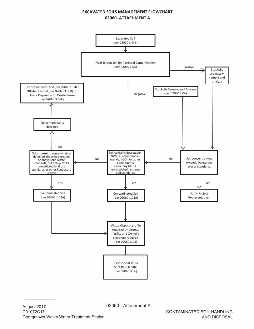
EXCAVATED SOILS MANAGEMENT FLOWCHART02060 -ATTACHMENT A
Positive
No
No No
Yes Yes Yes
Excavated Soil(per 02060 1.04B)
Screen Soil for Potential Contamination(per 02060 3.03)
Uncontaminated Soil (per 02060 1.04E) Offsite Disposal (per 02060 3.0 B) or
Onsite Disposal with Onsite Reuse (per 02060 3.0 C)
Stockpile, Sample, and Analyze(per 02060 3.04)
No contaminantsdetected
Soil (per 02060 1.04A)
Contaminated Soil(per 02060 1.04A)
Notify ProjectRepresentative.
Waste disposal profilerequired by disposalfacility and Owner'ssignature required(per 02060 3.02)
exceeds DangerousWaste Standards
, , or other constituents
land use
Dispose of at RCRA Subtitle D landfill (per 02060 3.06)
CONTAMINATED SOIL HANDLING
AND DISPOSAL
________________
August 2017C01072C17Georgetown Waste Water Treatment Station
NegativeStockpile Sample, and Analyze
(per 02060 3.04)
Stockpile separately, sample and
analyze
02060 - Attachment A

This page intentionally left blank.

August 2017 C01072C17 Georgetown Wet Weather Treatment Station 02110 - 1 SITE CLEARING AND GRUBBING
SECTION 02110
SITE CLEARING AND GRUBBING
PART 1 GENERAL
1.01 SUMMARY
A. This Section specifies site clearing and grubbing.
1.02 QUALITY ASSURANCE (NOT USED)
1.03 SUBMITTALS
A. Procedures: Section 01300.
B. Log of Disposal Site and Quantities. Provide updated quantities monthly.
1.04 JOB CONDITIONS
A. Existing conditions: Determine the actual condition of the site as it affects the Work. Before Work, notify the Project Representative if conditions appear different than the Contract represents.
B. Site clearing and grubbing shall include the swale as indicated on the Drawings, portions of which are below the line of mean higher high water and subject to conditions of aquatic permits. Items to be cleared from the swale include all vegetation, logs, and other debris. Do not commence clearing and grubbing of swale until TESC controls and stormwater bypass are in place at the mouth of the swale. Do not conduct clearing and grubbing during tidal inundation, and at a minimum, place and anchor geotextile fabric over newly exposed surfaces prior to tidal inundation.
C. Protection: 1. Do not damage structures, landscaping, or vegetation adjacent to the Site. 2. Provide, erect, and maintain barricades, coverings and other types of protection measures
necessary to prevent damage to existing trees, structures, utilities, landscaping, and other features to remain in place on or adjacent to the Site.
3. Remove salvaged items in a manner that protects adjacent property, structures, vegetation and utilities.
4. Maintain benchmarks, monuments and other reference points. Re-establish if disturbed or destroyed.
D. Repair or replace property damaged by Contractor's activities.
E. Storage containers and other large items within the staging areas will be removed by others prior to Contractor occupation.
PART 2 PRODUCTS (NOT USED)
PART 3 EXECUTION
3.01 PERFORMANCE
A. Clearing and grubbing: 1. Notify Project Representative prior to commencement of clearing and grubbing activities,
including activities intended for survey or other site investigation work.

August 2017 C01072C17 Georgetown Wet Weather Treatment Station 02110 - 2 SITE CLEARING AND GRUBBING
2. Coordinate clearing and grading operations with erosion control requirements. 3. Unless otherwise indicated in the Drawings, do not remove trees or significant vegetation without
authorization from Project Representative. 4. Unless otherwise indicated, remove obstructions such as brush, trees, logs, poles, stumps, roots,
heavy sod, vegetation, rock, stones larger than six inches in any dimension, broken or old concrete and pavement, debris, and structures where the completion of the Work require their removal.
5. Grubbing shall consist of complete removal of roots, stumps, trash and other debris from graded areas so the Site is free of roots and debris.
6. Provide for legal off-site disposal. Submit information on disposal site and quantities per Section 01715.
B. Utility interference: Where existing utilities interfere with the Work, coordinate necessary relocation in accordance with Section 01195.
C. Protection: 1. Provide protection devices, including barricades, fencing, warning signs, lights and other items
necessary to ensure the security of, and safety within, the work site during this phase of the Work.
2. Notify the Project Representative when site clearing is complete.
END OF SECTION

August 2017 C01072C17 Georgetown Wet Weather Treatment Station 02121 - 1 DEFORMATION AND VIBRATION MONITORING
SECTION 02121
DEFORMATION AND VIBRATION MONITORING
PART 1 GENERAL
1.01 SUMMARY
A. This Section describes the limits on deformation and vibration at adjacent facilities, the requirements for assisting the Project Representative with monitoring, and reporting requirements.
B. Purpose: 1. Deformation Monitoring:
a. The deformation monitoring points provide reference points for monitoring vertical and horizontal ground movement and establish a baseline record of such movement.
b. Measurements of ground movement will provide the basis for the implementation of remedial measures to prevent possible damage to structures, utilities, and concrete pavements.
c. Remedial measures, if necessary, include modifications of construction procedures, repair or replacement of damaged facilities, and restoration to original conditions of any disturbed property, structure, utility, or pavement.
2. Vibration Monitoring: a. The vibration monitoring will determine if the equipment and methods used to complete the
work cause vibrations which equal or exceed a specified standard which could cause damage to existing facilities.
b. The data gathered will provide on-site feedback of the effects of specific operations and procedures which may, over an extended period, cause damage.
3. Operations that are found to cause vibration damage shall be modified to prevent damage from vibration.
C. Roles and Responsibilities: 1. Owner:
a. Provide surveying of deformation monitoring points during active construction, monitor vibrations, and provide Special Inspection reporting to the City of Seattle.
2. Contractor: a. Establish deformation monitoring points at locations directed by Project Representative b. Perform work in a manner that limits deformations and vibrations as specified herein c. Establish independent monitoring points as needed and provide monitoring of Contractor-
and Owner-installed points to verify that the limits are not exceeded. d. Install utility monitoring points at the locations directed by the Project Representative
1.02 QUALITY ASSURANCE (NOT USED)
1.03 SUBMITTALS
A. Procedures: Section 01300.
B. Name of the individual responsible for the installation and monitoring of the deformation and vibration monitoring systems.
C. Equipment used for monitoring.
D. Equipment and procedure to be used for pavement and slab breaking and removal, shoring installation and removal, excavation and compaction.
August 2017 C01072C17 Georgetown Wet Weather Treatment Station 02121 - 2 DEFORMATION AND VIBRATION MONITORING
E. Pre-construction coordinates and elevations of Contractor-installed points; points shall have a clear naming designation.
F. Daily reports of the: 1. Vibration readings with summary of companion work monitored and completed when alarm
values are exceeded. The coordinates and elevation of the monitoring equipment, description of vibration-inducing equipment and activity, distance of monitoring from vibration-inducing equipment, and offset to nearest facility of concern shall accompany all vibration readings.
G. Deformation readings submitted daily if alarm values are exceeded. Remedial measures as required.
H. Attachment details for attachment of monitoring points to existing structures.
I. Shop drawings for utility monitoring points.
1.04 DEFINITIONS
A. Critical utility: gas, water larger than 1 inch nominal diameter; fiber optic and all connecting manholes, structures, and appurtenances.
B. Robust utility: all utilities not defined as critical.
C. Rigid pavement: Portland Cement Concrete.
D. Deformation: The vector sum of movement in the X, Y, and Z directions measured at a monitoring point.
1.05 CONTRACTOR-FURNISHED POINTS
A. Monitoring points indicated in the Drawings are the minimum locations that will be monitored by the Owner. The Contractor shall install additional deformation points at locations other than those indicated in the Drawings to assess the impacts of work.
B. The Project Representative will share monitoring information, but the Contractor shall not rely upon the Owner’s monitoring to verify that deformations and vibrations do not exceed the specified values.
C. Make deformation and vibration points and indicators available to the Project Representative for monitoring.
D. Inform the Project Representative in writing of the description and locations of such additional deformation and vibration points and submit details of attachments to existing structures, details of utility monitoring points, and installation details.
E. Deformation Monitoring: Deformation data shall be collected by the Contractor's identified personnel and shall be submitted daily if alarm values are exceeded. 1. Deformation shall be determined by optical survey methods. 2. The accuracy of the optical survey methods shall be within 0.01 feet.
PART 2 PRODUCTS
2.01 SURFACE DEFORMATION MONITORING POINT
A. Reference targets, reflectors, or P.K. nails mounted on structures, poles, or pavements.
B. Minimum 18-inch long rebar for subgrade monitoring.

August 2017 C01072C17 Georgetown Wet Weather Treatment Station 02121 - 3 DEFORMATION AND VIBRATION MONITORING
C. Compatible with the surveying or data acquisition system.
D. Capable of being read to the required accuracy.
E. Permanently attached to the feature being monitored by adhesive or other means that will not damage the facility.
F. Have a tag or permanent marking showing the unique identification number.
G. Protected from damage.
2.02 UTILITY MONITORING POINT
A. As shown in the Ground Monitoring Details in the Drawings or Contractor’s approved shop drawing.
PART 3 EXECUTION
3.01 MONITORING FOR DEFORMATION
A. General: 1. Perform monitoring as required to verify that the work does not cause deformations to exceed the
values shown in Table A. 2. Assist the Owner in establishing, reading, maintaining, and repairing monitoring points.
a. Assume approximately 34 on-shore and 8 off-shore points will be established at locations directed by the Project Representative, which will include the following: 1) The columns on bridge piers adjacent to the drop structure. 2) The SPU North Utilidor shaft. 3) All 4 corners of the WSDOT maintenance building and the outside cabinets and
transformer pad. 4) A minimum of 4 points along the ground above the communications conduit between the
utilidor shaft and the WSDOT maintenance building. 5) All utilities within 50 feet of the drop structure and Storm Treatment Facility. 6) At least 2 legs of the PSE transmission tower. 7) The edges of the pile cap and dolphin above the diffuser 8) At least 3 points along the railroad tracks adjacent to the Storm Treatment Facility.
b. Coordinate with the Project Representative to locate the points at locations that will minimize disruptions to the Contractor’s work, be protected from damage, and provide unobstructed lines of sight for monitoring.
c. Provide boat access, vactor truck, and access to monitoring locations for Owner resources to set monitoring points.
d. Notify the Project Representative immediately if monitoring points are damaged or displaced. e. Replace or repair damaged or deformed points at the direction of the Project Representative.
B. All elevations shall be referenced to fixed points which are a minimum of 500 feet away from excavations to assure that the reference points remain accurate.
3.02 MONITORING FOR VIBRATION
A. Employ construction activities that minimize vibrations transmitted through the soil to nearby houses, buildings, structures, or utilities.
B. The maximum allowable particle velocity at the nearest existing facility shall be as noted herein.
C. Measurements shall be taken with a recording device located at the house, building, structure, above-grade utility appurtenance (e.g., manhole, valve box), or nearest ground over utility.
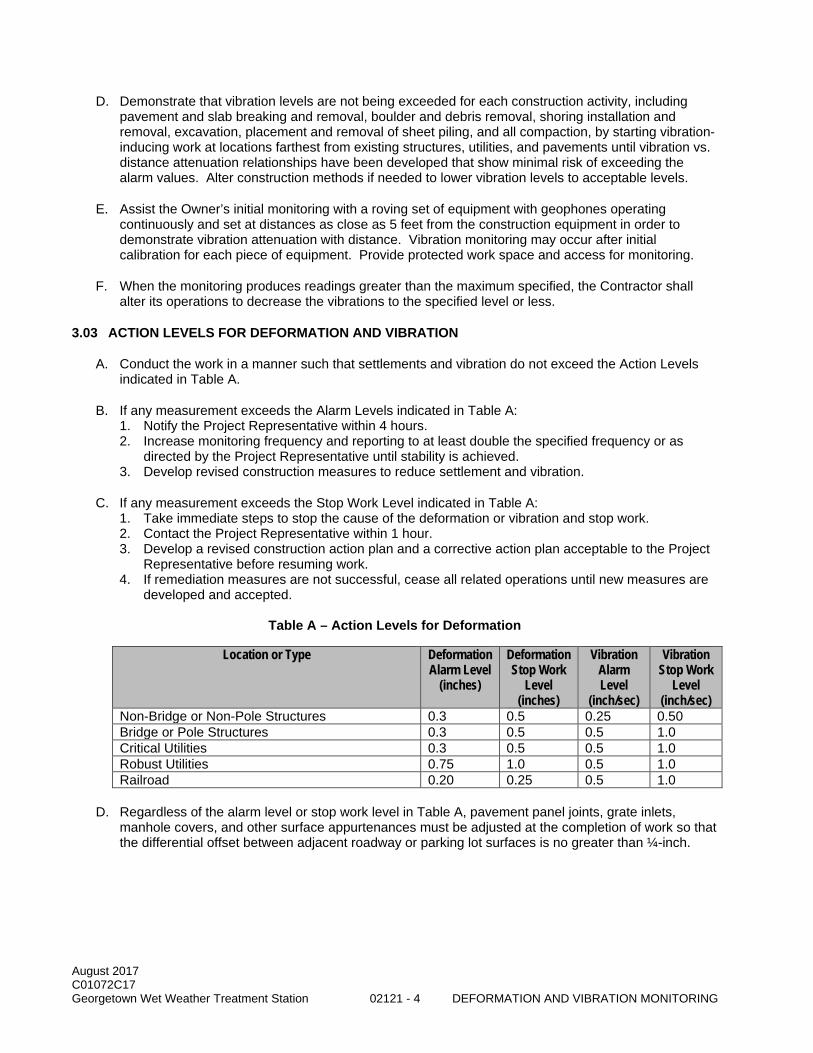
August 2017 C01072C17 Georgetown Wet Weather Treatment Station 02121 - 4 DEFORMATION AND VIBRATION MONITORING
D. Demonstrate that vibration levels are not being exceeded for each construction activity, including pavement and slab breaking and removal, boulder and debris removal, shoring installation and removal, excavation, placement and removal of sheet piling, and all compaction, by starting vibration-inducing work at locations farthest from existing structures, utilities, and pavements until vibration vs. distance attenuation relationships have been developed that show minimal risk of exceeding the alarm values. Alter construction methods if needed to lower vibration levels to acceptable levels.
E. Assist the Owner’s initial monitoring with a roving set of equipment with geophones operating continuously and set at distances as close as 5 feet from the construction equipment in order to demonstrate vibration attenuation with distance. Vibration monitoring may occur after initial calibration for each piece of equipment. Provide protected work space and access for monitoring.
F. When the monitoring produces readings greater than the maximum specified, the Contractor shall alter its operations to decrease the vibrations to the specified level or less.
3.03 ACTION LEVELS FOR DEFORMATION AND VIBRATION
A. Conduct the work in a manner such that settlements and vibration do not exceed the Action Levels indicated in Table A.
B. If any measurement exceeds the Alarm Levels indicated in Table A: 1. Notify the Project Representative within 4 hours. 2. Increase monitoring frequency and reporting to at least double the specified frequency or as
directed by the Project Representative until stability is achieved. 3. Develop revised construction measures to reduce settlement and vibration.
C. If any measurement exceeds the Stop Work Level indicated in Table A: 1. Take immediate steps to stop the cause of the deformation or vibration and stop work. 2. Contact the Project Representative within 1 hour. 3. Develop a revised construction action plan and a corrective action plan acceptable to the Project
Representative before resuming work. 4. If remediation measures are not successful, cease all related operations until new measures are
developed and accepted.
Table A – Action Levels for Deformation
Location or Type Deformation Alarm Level
(inches)
Deformation Stop Work
Level (inches)
Vibration Alarm Level
(inch/sec)
Vibration Stop Work
Level (inch/sec)
Non-Bridge or Non-Pole Structures 0.3 0.5 0.25 0.50 Bridge or Pole Structures 0.3 0.5 0.5 1.0 Critical Utilities 0.3 0.5 0.5 1.0 Robust Utilities 0.75 1.0 0.5 1.0 Railroad 0.20 0.25 0.5 1.0
D. Regardless of the alarm level or stop work level in Table A, pavement panel joints, grate inlets, manhole covers, and other surface appurtenances must be adjusted at the completion of work so that the differential offset between adjacent roadway or parking lot surfaces is no greater than ¼-inch.

August 2017 C01072C17 Georgetown Wet Weather Treatment Station 02121 - 5 DEFORMATION AND VIBRATION MONITORING
3.04 REMOVAL AND DECOMMISSIONING OF GEOTECHNICAL INSTRUMENTATION
A. Remove Contractor- and Owner-installed monitoring points prior to restoration in the area of the monitoring.
B. Obtain written approval from the Project Representative prior to decommissioning any monitoring point.
C. Restore disturbed or damaged surfaces as indicated in the Drawings or if not indicated, to the conditions existing before installation.
END OF SECTION

August 2017 C01072C17 Georgetown Wet Weather Treatment Station 02121 - 6 DEFORMATION AND VIBRATION MONITORING
This page intentionally left blank.

August 2017 C01072C17 Georgetown Wet Weather Treatment Station 02140 - 1 DEWATERING
SECTION 02140
DEWATERING
PART 1 GENERAL
1.01 SUMMARY
A. This Section specifies the definition, design, responsibilities, operation, maintenance, decommissioning, and execution of dewatering and associated reporting requirements.
1.02 QUALITY ASSURANCE
A. Referenced Standards: This Section incorporates by reference the latest revision of the following documents. These references are a part of this Section as specified and modified. In case of conflict between the requirements of this Section and those of the listed documents, the requirements of this Section shall prevail. Reference Title Chapter 173-160 WAC Minimum Standards for Construction and Maintenance of Wells AWWA A100 Standard for Water Wells Chapter 173-200 WAC Water Quality Standards for Groundwaters of the State of Washington WAC 296-155-66401 Appendix A – Soil Classification WAC 296-155-66403 Appendix B - Sloping and Benching
B. Qualifications: 1. Dewatering System Designer:
a. Professional Engineer or Hydrogeologist with geotechnical training licensed in the state of Washington.
b. At least 5 years of dewatering design experience with construction verification. c. Specific experience designing dewatering systems, calculating drawdown and dewatering-
related settlement, and filter criteria for similar conditions on at least 3 projects in the past 10 years.
2. Dewatering Installer: a. A minimum of five years’ experience in the design, operation, maintenance, and
decommissioning of similar Dewatering Systems. b. A minimum of five completed dewatering projects including at least two projects using the
proposed dewatering methods. c. Well driller licensed in the state of Washington.
1.03 SUBMITTALS
A. Procedures: Section 01300.
B. Qualifications: 1. Dewatering System Designer. 2. Dewatering Installer. 3. Well driller if different than system installer.
C. Groundwater Control Plan including details of shoring, tremie seal, ground improvement or other means combined with dewatering to provide a dry excavation where required.
D. Submit Groundwater Control Plan concurrent with Excavation Support System (Section 02161) and Protection and Maintenance of Property and Work (Section 01195) submittals.

August 2017 C01072C17 Georgetown Wet Weather Treatment Station 02140 - 2 DEWATERING
E. Dewatering System Installation documentation and information: 1. Within seven days of completion of well development: 2. Drilling logs that include:
a. Drilling method, location, unique well designation, soil descriptions, Groundwater conditions, and borehole depth.
3. Drilling Notice of Intents and Ecology Well Tags. 4. Well development records. 5. Dewatering Well and Observation Well diagrams that include:
a. Well material and diameter. b. Total depth. c. Well screen material, slot size, length, and interval depth. d. Filter Pack material and interval depth. e. Seal material and interval depth.
6. Certificate of filter pack material quality and gradation. 7. Flow meter calibration reports.
F. As-built drawings
G. Decommissioning documentation, Notice of Intent to Decommission a Well forms.
H. Calculations of uplift resistance for any tremie slabs utilized for groundwater control.
I. Meter calibration documentation.
J. Well Decommissioning Documentation: 1. Notices of Intent to Decommission a Well filed with the Department of Ecology. 2. Department of Ecology Resource Protection Well Reports. 3. Documents required by the Department of Ecology and other permitting agencies. 4. Daily field reports describing decommissioning procedures and materials and photographs of site
restoration.
1.04 DEFINITIONS
A. General: In addition to the definitions below, use the definitions listed in WAC 173-160-111 and WAC 173-200-020 for work of this Section.
B. Annular Space (or Annulus): The space between the soil surface of the wall of the drilled hole and the outer surface of the well casing.
C. Aquifer: Geologic formation, group of formations, or part of a formation that is saturated and sufficiently permeable to transmit water to Pumped Wells, Wellpoints, Eductors, and Sumps.
D. Artesian or Confined Aquifer: An Aquifer bounded by soil or rock layers of lower permeability than the Aquifer itself with the Groundwater level in a well tapping the Aquifer rising above the bottom of the overlying confining layer.
E. Depressurization: Reduction of the hydrostatic pressure that exists due to the presence of water with a Confined Aquifer.
F. Depressurization Well: A Pumped Well designed to reduce the hydrostatic heads/pressures within the subsurface soil profile.
G. Dewatering: Removal and lowering of Groundwater levels or hydrostatic heads within the subsurface soil profile.

August 2017 C01072C17 Georgetown Wet Weather Treatment Station 02140 - 3 DEWATERING
H. Dewatering System: A system of Pumped Wells, Wellpoints, and Sumps that will lower the water table and confined hydrostatic pressure adequately to permit safe working conditions and excavation stability.
I. Dewatering Well: See ‘Pumped Well’.
J. Eductor: A Dewatering Well with a water jet pump that creates a vacuum (negative pressure) by circulating clean water at high pressure through a nozzle and Venturi arrangement located in a well.
K. Existing Well: Wells installed prior to commencement of construction activities for this Contract.
L. Filter Pack: Clean, well rounded, smooth, uniform, sand or gravel, which is placed in the Annulus of the well between the borehole wall and the outside surface of the Well Screen.
M. Flowing Artesian: A Confined Aquifer with a Groundwater level above the ground surface.
N. Formation: An assemblage of earth materials grouped together into a unit that is convenient for description or mapping.
O. Groundwater: Water in a Saturated Zone or stratum beneath the surface of land or below a surface water body.
P. Groundwater Level: For each Aquifer, the level at which the surface of the water in a well Screened in the Aquifer would reach static equilibrium.
Q. Observation Well: A well designed to measure the depth to Groundwater or hydrostatic head in an Aquifer.
R. Perched Groundwater: Groundwater separated from an underlying body of Groundwater by unsaturated soil.
S. Pumped Well: A hole in the ground with a casing and Screen that includes its own motorized pump in the casing or Screen to lift water to the surface.
T. Saturated Zone: The part of the Unconfined Aquifer below the water table where the soil pores are completely filled with water.
U. Screen (Well Screen): A cylinder of steel or plastic material used to allow water to enter a well while preventing sediment or rock particles from entering the well.
V. Sump: Shallow hole in the ground adjacent to or in excavation trench with a slotted or perforated casing containing a pump and surrounded by filter pack to prevent the pumping of Formation material.
W. Vibrating Wire Piezometer (VWP): A sensor designed for measurements of the pore water pressure in soil. A VWP utilizes a stainless steel diaphragm to which a vibrating wire element is connected.
X. Well: Per Chapter 173-160 WAC.
Y. Wellpoint: A short slotted or perforated Screen (generally less than four inches in diameter and five feet long) attached to a riser pipe and typically jetted, driven or installed in a drilled hole.
Z. Wellpoint System: The system that consists of a number of well points placed at close intervals along and attached to a common header and a Wellpoint System pump.

August 2017 C01072C17 Georgetown Wet Weather Treatment Station 02140 - 4 DEWATERING
1.05 RESPONSIBILITIES
A. Dewatering System Designer: 1. Design Dewatering Systems in coordination with shoring to provide a dry excavation for
construction of the drop structure and piping to the east of the drop structure, and control groundwater in other segments to maintain stable excavations and construct the work
2. Review installation, development, performance, monitoring, and decommissioning of Dewatering Systems.
3. Attend Progress Meetings if requested.
B. Dewatering Installer: 1. Coordinate with Dewatering System Designer, Shoring Designer and Constructor. 2. Verify that installation meets the Dewatering System and Shoring System design. 3. Provide data reports, installation documentation, and decommissioning documentation.
1.06 DESIGN REQUIREMENTS
A. Limit dewatering efforts to localized areas for specific excavations and to limit dewatering-induced settlement as required by Section 02121.
B. Provide a dewatering system to maintain dry work areas without causing settlement of adjacent structures, pavements, or utilities, as specified in Section 02121.
C. Minimize the horizontal and vertical limits of groundwater drawdown.
D. Groundwater shall be handled and treated in accordance with Section 02271 and the King County Industrial Waste Discharge Permit.
E. Provide appropriate filters and screens to retain the pre-existing soil in contact with dewatering sumps or screens and preclude piping or internal erosion of the soil formation.
F. The development, drilling, and decommissioning of wells shall comply with Chapter 173-160 WAC.
G. Design Criteria for Dewatering Systems: 1. Design using accepted and professional methods of design and engineering consistent with the
best practice. 2. Include items such as wells, wellpoints, sumps, shoring, ground improvement and other
equipment, appurtenances and related earthwork necessary to perform the function. 3. Dewatering can affect improvements in the work and surrounding area. Take adequate
precautions in the design and implementation of the dewatering plan to protect existing improvements and avoid damage thereto.
1.07 GROUNDWATER CONTROL PLAN
A. Shall consist of the following: 1. Dewatering System for each type and location of Dewatering. 2. Design drawings showing the size, depth, and location of system components, monitoring
instruments, and discharge locations. a. Discharge water requirements and locations are per the discharge permit. b. Locations and workings of primary and backup power supply.

August 2017 C01072C17 Georgetown Wet Weather Treatment Station 02140 - 5 DEWATERING
3. Monitoring: Provide Dewatering System(s) monitoring plan. a. Include Observation Wells at minimum spacing of 30 feet along upgradient side of tight
shoring that is not designed for full differential water head between high groundwater and low tide.
b. Instrument type and monitoring schedule for Contractor designed Dewatering System monitoring plan.
4. Design calculations stamped, dated, and signed by the Designer, including: a. Anticipated flows from the Dewatering System and anticipated volume at each location of
discharge. b. Selection of appropriate filter material, screen size and well diameter. c. Analyses/calculations supporting the capacities of proposed systems. d. Projected water level drawdown in Dewatering Wells, Wellpoints, and Observation Wells. e. Dewatering System capacity and adequacy, including adequacy of selected equipment. f. Assumptions used to develop the Groundwater Control Plan.
5. Schedule for installation, sequencing, maintenance, and removal of the Dewatering System. 6. Drilling and development techniques and method for measuring sufficiency of development. 7. Sealing plan in accordance with WAC 173-160-251 requirements for Dewatering Systems
installed in the Confined Aquifer. 8. Complete description of equipment, material, and instrumentation to be used, with installation,
start up, operation, and maintenance procedures. Include calibration documentation for instrumentation.
9. Contingency Plan for: a. Maintaining Dewatering System operation during power outage.
B. As-built drawings: 1. Plan drawing showing the as-built locations of Wells and Wellpoints as well as pumps and
associated piping.
C. Well Decommissioning Work Plan: 1. Schedule of activities. 2. Method and procedures of decommissioning approach in accordance with Chapter 173-160
WAC. 3. List of materials and equipment to be used. 4. Decommissioning of wells installed in a Confined Aquifer shall include drilling out the well casing.
Include specific methods, materials, and procedures for Artesian Dewatering Well decommissioning and sealing.
5. Driller’s water well license number and qualifications. 6. Waste management procedures. 7. Variances, if any approved.
1.08 EXISTING OBSERVATION POINTS
A. Locations of existing observation and monitoring wells are shown in the Geotechnical Data Report.
1.09 PERMIT REQUIREMENTS
A. Be responsible for all the conditions of the Industrial Waste Discharge Permit attached to Section 01062, including monitoring, testing, and reporting.
B. Be responsible for obtaining all permits from the state and local authorities having jurisdiction.

August 2017 C01072C17 Georgetown Wet Weather Treatment Station 02140 - 6 DEWATERING
PART 2 PRODUCTS
2.01 FILTER MATERIAL
A. Clean, rounded, washed select silica gravel and sand, free from silt, clay and other deleterious material.
B. Use filters and filter packs such that soils are not subject to removal of fines upon pumping.
2.02 WELL SCREEN
A. Factory-slotted and sized appropriately for the filter pack and formation to prevent the removal of fines from the filter pack or formation. Groundwater entrance velocities through the well screen shall equal 0.01 feet per second or less.
2.03 SUMPS
A. Sumps shall include a slotted or perforated casing surrounded by filter pack to prevent movement of fines.
2.04 FLOW METERS
A. Capable of measuring the flow from a Dewatering Well System within ten percent of the actual flow.
B. Capable of reporting current flow in gallons per minute and total flow volumes in gallons or cubic feet.
C. Factory calibrated within one year of data acquisition.
D. Sized to account for the anticipated and actual flow rate of the well or discharge being monitored.
2.05 STANDBY EQUIPMENT
A. Maintain on Site sufficient equipment and materials for continuous and successful operation of the Dewatering System and monitoring systems.
B. If using electric pumps, provide 100 percent standby electrical generating capacity with automatic switching from line to generator, including safety features to prevent back-feeding the electrical supply system.
C. Maintain on Site a sufficient number of valves, tees, elbows, connections, tools, recorder charts and parts or other system hardware to insure immediate repair or modification of any part of the system as necessary.
PART 3 EXECUTION
3.01 GENERAL
A. Perform dewatering in accordance with the Specifications and Groundwater Control Plan. Keep the Project Representative advised of changes made to accommodate field conditions.
B. Upon completion of the Dewatering System installation, revise and resubmit as-built drawings and installation logs to indicate current configuration of the system.
C. Notify the Project Representative a minimum of 48 hours prior to the start of Well or Wellpoint construction.
August 2017 C01072C17 Georgetown Wet Weather Treatment Station 02140 - 7 DEWATERING
D. Organize and schedule dewatering operations to maintain the groundwater level within excavations as required for execution of the work.
E. Comply with Chapter 173-160 WAC for development, drilling, and decommissioning of wells.
F. Prevent damage to adjacent buildings, structures, utilities, and other work that may result from settlement or other groundwater related effects.
G. Dewater and dispose of the water so as not to cause injury to public, private, or other property, or to cause a nuisance or a hazard to the public.
H. Operate Dewatering System continuously until completion of backfill and compaction, or installation and curing of structurally connected invert slab.
I. At all times have on hand sufficient pumping equipment and machinery in good working condition for ordinary emergencies, including power outage and flooding, and have available at all times for the continuous and successful operation of the dewatering and monitoring systems. These systems shall not be shut down between shifts, on holidays, or weekends, or during work stoppages, without written permission from the Project Representative.
J. The control of groundwater shall be such that softening of the sides or bottom of excavations, or formation of "quick" conditions or "boils" during excavation shall be prevented. Design and operate dewatering systems to prevent removal of the natural soils. Maintain water levels a minimum of two feet below the bottom of excavations at all times and under all conditions.
K. Except where dewatering is prohibited as specified in the Dewatering Restrictions article of this specification, excavations shall be kept free of water during excavation, construction of structures, installation of pipelines, placement of gravel working base, structure and trench backfill, and the placement and setting of concrete below grade.
L. Control surface runoff so as to prevent entry or collection of water in excavations or in other isolated areas of the site.
M. Employ the services of a subcontractor who is experienced in the field of dewatering design, installation, operation, and maintenance. Visit the site to determine the existing conditions thereof.
N. Do not solely employ open and cased sumps for excavations deeper than two feet below a perched or static water level unless permitted by the Project Representative and the excavation is in competent soils ( WAC 296-155-66401 and WAC 296-155-66403 for Type A soils) and which do not cave or unravel when seepage within the competent soils occur.
O. Provide a copy of required documentation filed with and received from the Department of Ecology for wells.
P. Be solely responsible for proper design, installation, operation, maintenance, and failure of any component of the Dewatering System.
Q. Furnish materials, tools, equipment, facilities, and services as required for the dewatering work.
R. Provide equipment and fittings for monitoring sand content.
S. Meet noise requirements. Section 01560.
T. Meet the requirements of Section 02271 for discharge of dewatering water.

August 2017 C01072C17 Georgetown Wet Weather Treatment Station 02140 - 8 DEWATERING
3.02 PUMPS AND DISCHARGE PIPING
A. Use pumps for Dewatering Wells and Wellpoint systems that are industry standard for the applications specified herein with sufficient capacity, head, horsepower, wiring, fittings, and switching facilities to maintain continuous operation throughout the operation of the Dewatering System.
B. Provide pipe of sufficient diameter to minimize the friction loss and backpressure to accommodate the flows necessary to achieve the specified drawdown within the total dynamic head limits of the pumps.
C. Design vacuum header for Wellpoints with allowances for friction losses to convey extracted groundwater to the vacuum pump.
D. Provide auto dialer third party service to notify the Contractor Representative and the Project Representative when the operating Dewatering System is not functioning properly.
E. Pumped Well Systems: provision, install, operate, maintain and remove risers, discharge pipe, headers, manifolds, fittings, valves, and other piping hardware necessary to transport pumped water to the treatment system.
3.03 DISCHARGE POINTS
A. Dewatering discharge from Pumped Wells and Sumps shall be routed through the treatment system prior to being discharged per Section 02271 and 02060.
B. Water discharged shall meet the requirements of the permit requirements related to the discharge permit listed in Section 01062.
3.04 DEWATERING SYSTEM PROTECTION
A. Take reasonable precautions necessary to ensure continuous, successful operation of the system. This includes adequate marking of well, pump and pipe locations.
B. Wherever dewatering wells, vacuum headers or discharge lines are to be crossed for access and egress, use steel ramps to protect the system from vehicular traffic. Ramps shall be capable of supporting the heaviest equipment on site and shall provide at least one foot of clearance between the dewatering system element and the underside of the ramp.
C. Clearly identify with brightly colored or flagged 8-foot high poles on each side of the access point, vehicular access points across the dewatering system.
3.05 WELL DEVELOPMENT AND FORMATION PROTECTION
A. Develop wells and wellpoints after installation to remove fines from jetting, drilling, and installation.
B. Develop the Wells until the sand content of the discharge water during surging is less than 20 parts per million (ppm) as determined by a centrifugal, separating meter such as a Rossum Sand Tester, or equivalent, in accordance with AWWA A100.
C. Be responsible to replace Pumped Wells that produce more than 20 ppm sand/silt.
D. Develop wells to remove fines resulting from drilling and construction and to increase the yield and hydraulic connection with the Aquifer.

August 2017 C01072C17 Georgetown Wet Weather Treatment Station 02140 - 9 DEWATERING
E. Discharge of development water: 1. Discharge to treatment system. 2. Discharge directly to the ground surface or surface water body is prohibited. 3. Discharge shall meet the requirements of Section 02271.
F. In the event the wells installed do not achieve the target drawdown, conduct additional well development in the presence of the Project Representative. Redevelop or replace the poor performing wells and be responsible for impacts.
G. Submit development records for Pumped Wells including date, method, rate and length of development, drawdown, discharge and solids concentration at the beginning of development and drawdown, discharge and solids concentration at the end of development.
H. Monitor system discharge solids content daily for one week after installation of, or restart after shut down of WellPoint, Pumped Well, or sump, and weekly thereafter.
I. Discharge solids content from Sump/drain trench discharge shall be monitored daily.
J. Operate Dewatering Systems so that soil fines are not removed from native and foundations soils.
3.06 MONITORING SYSTEM
A. Maintain an accurate and continuous record of water level, quality, sand content, and flow information. Report to the Project Representative the specific member(s) of the work force responsible for collecting and reporting the required information.
B. Flow meters: 1. Install flow meters on Dewatering System discharge pipes, each Eductor pump return flow to the
reservoir, Pumped Well, and Wellpoint pump discharge line, and each pump used for the collection of groundwater seepage from the excavation.
2. Where diversions of discharge occur, install additional flow meters to ensure that water pumped from excavations is metered.
3. Install flow meters to manufacturer's specifications.
C. Additional monitoring wells as needed to verify performance.
3.07 WEEKLY DATA REPORTS
A. Data shall be readable in Microsoft Excel.
B. For each well provide: 1. Installation date. 2. Location. 3. Type. 4. Total flow indicated on flow meter. 5. Rate of flow, measured daily. 6. Sand content data, measured weekly in accordance with AWWA A100. 7. Decommissioning date.
3.08 DAMAGES
A. Repair damage to work in place from installation, operation, or failure of the Dewatering System.
August 2017 C01072C17 Georgetown Wet Weather Treatment Station 02140 - 10 DEWATERING
3.09 MAINTAINING DRY EXCAVATION IN DEWATERED CONDITION
A. Maintain the dewatering systems in operation at all times.
B. Provide personnel skilled in the operation, maintenance, and replacement of system components; standby and spare equipment of the same capacity and quantity, and other work required to maintain the systems.
C. Dewatering shall be a continuous operation and interruptions due to outages or other reasons shall not be permitted.
3.10 AVAILABLE SOIL TEST DATA
A. As noted in Section 01036.
B. Use of available soil test information in no way relieves responsibility for design, installation, and operation of a properly functioning dewatering system.
3.11 SYSTEM REMOVAL
A. Notify Project Representative for approval to decommission Wells no less than one week prior to decommissioning.
B. Dewatering Wells, Wellpoints, Observation Wells, VWPs, and County installed Wells and VWPs shall be decommissioned prior to Substantial Completion.
C. Decommissioning: 1. Decommission Existing Wells, Dewatering System (s), and instrumentation used to monitor the
Dewatering System (s) Chapter 173-160 WAC, including specific standards for surface sealing (WAC 173-160-231), Formation Sealing (WAC 173-160-241), and sealing requirements for Artesian wells (WAC 173-160-251) and according to the Well Decommissioning Work Plan unless directed otherwise in writing by the Project Representative.
2. Remove Dewatering pumps, pipes and other assorted system hardware from the Site. 3. Well decommissioning shall be by a state of Washington licensed water well contractor. 4. During decommissioning, do not interfere with site operations. 5. After decommissioning, restore disturbed or damaged surfaces as indicated in the Drawings, or if
not indicated, to the conditions existing before the installation meeting the satisfaction of the property owner or Authority having Jurisdiction.
6. When complete, submit evidence of well decommissioning.
3.12 DEWATERING RESTRICTIONS
A. Excavation Zone 1 indicated in the Drawings and all excavations related to the Water Treatment Facility: 1. Measures to limit the potential effects of dewatering-related settlement and potential migration of
contaminated groundwater are required where dewatering outside a sealed cofferdam is proposed. a. Submit calculations for drawdown outside of shoring and accompanying settlement, verifying
that settlement will not exceed the limits specified in Section 02121 nor damage the work or existing facilities.
2. If a tremie slab is proposed, submit calculations showing resistance to uplift forces and a minimum factor of safety of 1.2 during construction, ignoring side friction between the tremie seal and vertical shoring unless reinforcing connections are provided between the vertical elements and the tremie concrete. With a tremie slab in place and dry excavation, the structural slab can be cast directly on the tremie slab.

August 2017 C01072C17 Georgetown Wet Weather Treatment Station 02140 - 11 DEWATERING
B. Excavavation Zone 2 indicated in the Drawings: 1. Excavation, placement of the pipe, and placement of backfill shall be done within a sheetpile
cofferdam through the water column. 2. Dewatering is not allowed inside or outside of the sheetpiles. 3. Differential water levels between the inside and outside of the sheetpiles shall be minimized and
controlled to not exceed the limits indicated in the Contractor’s excavation support system plan, as required by Section 02161.
C. Excavation Zone 3 indicated in the Drawings: 1. Dewatering is not allowed.
END OF SECTION

August 2017 C01072C17 Georgetown Wet Weather Treatment Station 02140 - 12 DEWATERING
This page intentionally left blank.

August 2017 C01072C17 EXCAVATION SUPPORT AND Georgetown Wet Weather Treatment Station 02161 - 1 WORK BRIDGE SYSTEMS
SECTION 02161
EXCAVATION SUPPORT AND WORK BRIDGE SYSTEMS
PART 1 GENERAL
1.01 SUMMARY
A. This Section specifies requirements for Contractor-designed excavation support systems of trenches, shafts, trenchless pits, and open excavations greater than four feet in depth.
B. Excavation for the outfall shall be conducted within sheeted trenches as indicated in the Drawings. Comply with all provisions of the contract permits, including location, dimensions, and methods for placement and removal of trench sheeting within the Lower Duwamish Waterway.
C. Requirements for Contractor-designed temporary work bridge or trestle necessary to construct the new structure.
1.02 QUALITY ASSURANCE
A. Referenced Standards: This Section incorporates by reference the latest revision of the following documents. These references are a part of this Section as specified and modified. In case of conflict between the requirements of this Section and those of the listed documents, the requirements of this Section shall prevail. Reference Title Chapter 296-155 WAC, Part N Excavation, Trenching, and Shoring AISC Manual of Steel Construction, 13th Edition AWS D1.1 Structural Welding Code SBC Seattle Building Code WISHA Washington Industrial Safety and Health Administration *WAC WSDOT Standard Specification
Washington Administrative Code Washington State Department of Transportation Standard Specifications for Road, Bridge, and Municipal Construction, 2016 Edition
B. Qualifications: 1. Designer: Professional Engineer licensed in the state of Washington with a minimum of three
years of experience in designing earth retaining structures for temporary construction similar to the type and depth proposed in similar soil and groundwater conditions as this Contract.
2. Contractor: Minimum of three years-of-experience with the installation of earth retaining structures for temporary construction of similar type and depth proposed in similar soil and groundwater conditions as this Contract.
3. Welders shall hold current certification by AWS.
1.03 SUBMITTALS
A. Procedures: Section 01300.
B. Qualifications.
C. Excavation Support System Plan.
D. Designer certification that installed excavation support systems are in compliance with their design.

August 2017 C01072C17 EXCAVATION SUPPORT AND Georgetown Wet Weather Treatment Station 02161 - 2 WORK BRIDGE SYSTEMS
E. Plans and calculations for work bridge or trestle prepared by a Professional Engineer licensed in the state of Washington.
F. Submit concurrent with submittals for Groundwater Control Plan (Section 02140) and Protection and Maintenance of Property (Section 01195).
G. Joint sealant for sheet piles.
H. Methods and sequence for installation and removal of support systems, including details of how water quality provisions of permits will be met.
I. Debris containment BMP for work bridge.
1.04 DEFINITIONS
A. Obstructions: A specific object (including but not limited to, boulders, logs, and man-made objects) encountered during installation of the excavation support system which prevents or hinders the construction, such that the production rate is significantly reduced relative to the production rate for other portions of the excavation support system in the geologic unit that contains the obstruction and in similar surface conditions. This definition excludes reductions in the excavation support installation rate that are related to the excavation passing under or in very close proximity to existing utilities or structures.
B. Work Bridge: “Trestle” in these Contract Documents means the same thing as “Work Bridge.”
C. Zone of Influence: A 1.5H:1V (horizontal:vertical) downward projection from the bottom of the outside edge of an existing footing, duct bank, or horizontal projection outward 1.5D on each side of a pipe invert where D is the pipe outside diameter.
1.05 EXCAVATION SUPPORT SYSTEM PLAN
A. Design documents, including: 1. Detailed written description of excavation support system to be used, including materials,
required equipment, work sequence, and work schedule. 2. Design drawings and calculations prepared, stamped, dated, and signed by the Designer. The
calculations shall demonstrate the integrity of the proposed support system to withstand ground, groundwater, river water, and construction loads. Calculations shall clearly indicate maximum differential hydrostatic loads on shoring and describe how that differential will be maintained or limited. Calculations shall include seepage analyses to verify maximum flow gradient at ground surface for flows both into and out of shoring. Base stability calculations shall also be submitted. Include calculations for anticipated wall deflections and associated instrumentation.
3. Drawings shall include: a. Dimensions. b. Minimum section properties. c. Details of any guides or templates to be used. d. Locations of existing structures, utilities, right-of-way easements, public, and private
easements. e. Locations of geotechnical instrumentation and monitoring and limits on allowable movement. f. Maximum and minimum water elevation inside the shoring and system for maintaining those
water levels. 4. Methods and procedures for installing and removing excavation support systems. 5. Methods and procedures for temporarily supporting communications conduit crossed by the
trench. 6. Methods and procedures for temporarily supporting and releveling the transformer and cabinet
northwest of the WSDOT maintenance building. 7. Shop drawings and manufacturer literature for major equipment and installation systems.

August 2017 C01072C17 EXCAVATION SUPPORT AND Georgetown Wet Weather Treatment Station 02161 - 3 WORK BRIDGE SYSTEMS
8. Instrumentation Installation and Monitoring Plan as required by the Designer. 9. Layout and materials for debris containment system beneath work bridge decking.
B. Information required by Chapter 296-155 WAC, Part N.
C. Applicable requirements of WISHA for excavation and construction.
1.06 DESIGN REQUIREMENTS
A. Be responsible to adequately size and to ensure that the excavation support system design is free of errors and omissions that may affect its safety, functionality, or performance. 1. The Contractor accepts full responsibility for complying with relevant references, specifications,
and standards that apply to the design including those that are not named in this Section.
B. Be responsible to adequately size the piles, decking and internal bracing for the temporary work bridge or trestle within the footprint and configuration indicated in the drawings. 1. Construction and installation shall comply with all requirements for applicable agencies and
permits.
C. The design, planning, installation, and removal of excavation support systems shall be accomplished in such a manner as to maintain the required excavation or trench section and to maintain the undisturbed state of the soils below and adjacent to the excavation.
D. Design the excavation support system in accordance with Chapter 296-155 WAC, Part N.
E. When designing with material stresses for temporary construction higher than the allowable stresses prescribed in the AISC and the SBC, increase in such stresses shall not exceed 20 percent of the value of the prescribed stresses. Overstressing is not permitted for any element of the excavation support system.
F. Values for pile embedment and bending moment shall be determined by checking the piles using both the Free Earth and Fixed Earth Support methods using the larger value from either method for the toe embedment and moment. Bottom of sheet piles shall be a minimum of 10ft below bottom of excavation.
G. Struts are to be designed for the maximum load produced by the following methods of analysis: Free Earth Support or Fixed Earth Support method.
H. Horizontal strutting below the barrel of a pipe and the use of pipe as support are not acceptable.
I. Design to include dewatering requirements Section 02140 for support of the excavation and prevent inflow of surface water into the excavation.
J. Control ground movements and deformations in accordance with the specified requirements. If damage occurred, address vibration and settlement effects on the surrounding structures, utilities, and properties by damage avoidance measurements.
K. Where applicable, the design shall be in accordance with the SBC.
L. Soil parameters and loading criteria for trench sheeting (Station 11+20 to 13+00): 1. Use soil parameters in this Section as design parameters. Loading shall be increased as
necessary to account for construction activities, sequencing, and loading. 2. Determine water pressures and surcharge loads that may result from construction methods and
regulation of water levels within the shoring and design the earth support system for those additional pressures due to those loads.

August 2017 C01072C17 EXCAVATION SUPPORT AND Georgetown Wet Weather Treatment Station 02161 - 4 WORK BRIDGE SYSTEMS
3. Consider sequence of excavation and placement of the lateral support elements in the design of the temporary earth support structures.
4. Excavation support systems shall be designed to withstand anticipated loads from handling, ground, groundwater, surcharge, and adjacent facilities. These include earth pressure, hydrostatic pressure, surcharge loads from surface equipment, material storage, and construction loads.
5. Soil effective angle of internal friction, φ’ = 24 degrees. 6. Unsaturated soil total unit weight, γ = 100 pcf. 7. Soil effective unit weight, γ’ = 40 pcf. 8. Pile-to-soil interface angle, δ = 16 degrees. 9. Backslope angle: no less than horizontal, up to 1.5H:1V in vicinity Station 12+10. 10. Assume soil in backslope is saturated to the higher of groundline or MHHW. 11. Ignore passive resistance from upper 2 feet of soil. 12. Distribute surcharge loads to shoring from area of tracks or wheels unless crane mats or plates
are used to distribute load over wider area. 13. Control the water levels inside of the sheetpiles and provide sufficient depth of sheetpiles so that
the maximum upward flow gradient, imax, at the ground surface at the maximum allowable differential head is:
imax = ∆h/L < 0.4, where ∆h/L = change in head per unit depth.
M. Soil parameters and loading criteria for drop structure, stormwater treatment facility, and trench east of drop structure: 1. Designer determined based on proposed equipment, stockpiles, and interpretation of subsurface
conditions from the data referenced in Section 01036 supplemented by the Contractor’s optional explorations.
1.07 SUPPORT SYSTEM REQUIREMENTS
A. Assess existing conditions, including property rights of adjacent property whether private or public, for the possible effects of proposed temporary works and construction methods.
B. Obtain rights to enter property not obtained by the County.
C. Select and design excavation support systems, methods, and details to ensure safety to the public, adjacent property and the completed work.
D. Remove temporary work bridge or trestle when it is no longer needed. Satisfy all requirements of applicable permitting agencies during work bridge or trestle removal. Restore all areas occupied by the work bridge or trestle in accordance with restoration drawings.
E. Remove excavation support system upon completion of intended construction activities unless indicated otherwise in the drawings.
1.08 DESIGNER RESPONSIBILTIES
A. Excavation Support System Certification: 1. After review at the Site, the Designer shall certify in writing, at each level of bracing installed and
prior to proceeding with the excavation, that each excavation support system is constructed in general compliance with the Designer’s stamped, dated, and signed excavation support system design.
2. Designer shall also review and certify in writing the acceptability of modifications made by the Contractor during construction and revise the applicable drawings and submit to the Project Representative.

August 2017 C01072C17 EXCAVATION SUPPORT AND Georgetown Wet Weather Treatment Station 02161 - 5 WORK BRIDGE SYSTEMS
B. Review the Contractor daily reports and notify the Contractor of items that do not meet the requirements of the approved Excavation Support Plan. Contractor shall follow-up with the Designer to rectify and implement requirements of the Designer.
C. Meet, review, and confirm that applicable requirements of this specification are included in the as-constructed excavation support system.
D. Visit the Site of the work no less than once per week to review and confirm compliance with the approved permitted design and that it meets the requirements of this Section.
E. Provide inspection report of the site visit to the Contractor no less than weekly.
F. Review written quality control reports that include test results and field inspection reports as well as vibration and settlement monitoring results from the Contractor a maximum of weekly during the work for the previous week of work.
G. Meet with the Contractor on an as-needed basis to review completed work and identify items for the Contractor to modify for the constructed design to be accepted at the completion and prior to use of the excavation support system.
1.09 SITE CONDITIONS
A. See Section 01036.
PART 2 PRODUCTS
2.01 GENERAL
A. Joint sealant for sheet piles. 1. Apply sealant in sheet pile interlocks for all sheets for the cofferdam (Zone 2: between stations
12+00 and 13+06). Sealant shall be applied according to manufacturer’s recommendations.
B. Acceptable manufacturers: 1. Adeka Corporation. 2. PilePro Group. 3. Approved equal.
PART 3 EXECUTION
3.01 GENERAL
A. Construct the excavation support systems in such a manner as to not disturb the state of soil adjacent to the trench or excavation and below the excavation bottom.
B. Control water: Section 02140.
C. Construction activities shall comply with all applicable provisions of the contract permits, including the Corps of Engineers Nationwide Permit Authorization, Section 401 Water Quality Certification, WDFW Hydraulic Project Approval, WSDOT Franchise Agreement, and City of Seattle Shorelines Permit, which are included in Section 01062.
D. Designer shall inspect the constructed excavated support system prior to use and certify that the excavation support systems were built in conformance with the design. Multiple certifications may be required.

August 2017 C01072C17 EXCAVATION SUPPORT AND Georgetown Wet Weather Treatment Station 02161 - 6 WORK BRIDGE SYSTEMS
E. Excavation and backfill shall be in accordance with Section 02323.
F. Perform structural welding in accordance with the applicable clauses of AWS D1.1.
G. Site restoration shall be as indicated in the Drawings or to a condition equal to or better than that which existed prior to construction, if not indicated.
H. Vibratory pile driving shall be used preferentially over impact driving. Impact driving systems may be used with approved noise attenuation (see Hydraulic Project Approval Permit Condition 44 – Specification Section 01062).
I. The final sheet piling enclosing the cofferdam for Zone 2, which shall isolate the Zone 2 work area from the Duwamish Waterway, shall be installed during low tide when the swale is dewatered to prevent trapping fish. After the cofferdam enclosure is complete, fill cofferdam with water to comply with Section 02140, 3.12B of these specifications. Water from Duwamish Waterway used to fill the cofferdam must be equipped with a fish guard to prevent passage of fish into the diversion device pursuant to RCW 77.57.010 and 77.57.070. The pump intake shall be screened by one of the following: 1. Perforated plate: 0.094 inch (maximum opening diameter). 2. Profile bar: 0.069 inch (maximum width opening). 3. Woven wire: 0.087 inch (maximum opening in the narrow direction).
J. The minimum open area for all types of fish guards is 27%. The screened intake shall consist of a facility with enough surface area to ensure that the velocity through the screen is less than 0.4 feet per second. Screen maintenance shall be adequate to prevent injury or entrapment of juvenile fish and the screen shall remain in place whenever water is withdrawn from the water through the pump intake.
3.02 MOVEMENT MONITORING
A. Temporary shoring is to be installed for protection of personnel and adjacent existing facilities and utilities. Care shall be taken during the planning and construction of earth support systems to minimize settlements and displacements of existing facilities and utilities.
B. Contractor shall take sole responsibility for safety and integrity of the support system.
C. Detrimental Movements or Settlements: Work shall be stopped immediately where movement or deformation of support system may in any way impair the integrity of existing site improvements or the support system.
3.03 PRECLEARANCE SURVEY
A. Prior to performing excavations or installing sheet piles between Station 12+40 and the concrete drop structure, inclusive of the drop structure and the water treatment facility, the Contractor shall vacuum excavate one line along the outside limits of each sheet pile alignment to a depth of 10 feet or until caving makes the vacuum excavation diameter or width more than 6 inches larger than the uncaved diameter or width, whichever is less.
B. The Project Representative shall be informed of all preclearing operations a minimum of 3 working days in advance.
C. The Contractor shall produce a Preclearance Survey Report that includes: 1. A log of the type, size, and percentage of materials over 6 inches in maximum dimension,
determined by visual estimation, in minimum 20-foot stations along each precleared line.

August 2017 C01072C17 EXCAVATION SUPPORT AND Georgetown Wet Weather Treatment Station 02161 - 7 WORK BRIDGE SYSTEMS
2. The horizontal and vertical location, material type, diameter, and treatment of pipe and conduit encountered. Treatment shall identify if the pipe or conduit was cut and capped, removed (and to what limits), or protected in place.
D. Preclearance excavations shall be backfilled within 8 hours of excavation or before the tide can flood the excavation.
E. The Contractor is responsible for overruns in planned backfill quantities and is responsible for damage to existing facilities due to preclearance caving; the Contractor is urged to backfill as quickly as possible.
F. Backfill: 1. Controlled Density Fill backfill shall be located or designed to provide strength that does not
interfere with shoring installation and shall be installed by tremie or placement of the dispensing chute into the bottom of the precleared trench so that loose sidewall material cannot be trapped beneath the dispensed material.
2. Granular materials shall be placed in a manner to preclude bridging. The Contractor shall continuously sound the excavation during backfilling to verify that voids are filled.
3.04 INTERNAL BRACING SUPPORT SYSTEM
A. All bracing support members, if required, shall be installed and maintained in tight contact with each other and with the surface being supported.
B. Bracing members, if required, shall be preloaded by jacking the struts in accordance with loads, methods, procedures, and sequence as indicated on approved shop drawings. The Contactor shall coordinate excavation work with bracing installation and preloading. The Contractor shall weld struts in place to maintain the preloading force in the bracing after release of the jacking equipment pressure. The Contractor shall use procedures so as to produce uniform bracing member loading without appreciable eccentricities, overstressing, or support member distortion. Jacking points shall be designed by the Contractor.
C. Bracing and web stiffeners shall be provided as needed to prevent rotation, crippling, or buckling of connectors at points of bearing between structural steel members. Allow for eccentricities resulting from field fabrication and assembly. Wales shall be installed free for twists and deformations.
D. Excavations shall be to a depth no more than 3 feet below the elevation of any support member about to be placed. The support member shall be installed and preloaded immediately after installation and prior to continuing excavation. Benched excavations require pre-approval by the Project Representative.
3.05 REMOVAL OF SUPPORT SYSTEMS
A. Where removal is required wholly or in part, such removal shall be performed by vibrating methods in a manner that shall not disturb or damage adjacent new or existing improvements, construction, or utilities.
B. As indicated in the Drawings, cut trench sheeting minimum two feet below finished grade and leave sheeting in place below cutoff.
C. All excavation support system components left in place shall be accurately marked on the record drawings to show the extent (horizontal and vertical) and the materials.

August 2017 C01072C17 EXCAVATION SUPPORT AND Georgetown Wet Weather Treatment Station 02161 - 8 WORK BRIDGE SYSTEMS
3.06 OBSTRUCTIONS
A. Concrete and asphalt rubble and other impediments to piling and excavation are present in the area of required trench shoring. These materials shall be moved as necessary to install the shoring system. Rubble may be temporarily placed along the shoreline to provide erosion protection of the adjacent shoreline after shoring is installed, but shall be removed prior to final site restoration.
B. If, during the course of the work, unanticipated obstructions are encountered, the Project Representative shall be immediately notified. Corrective measures shall be provided by the Contractor to and accepted by the Project Representative before further work.
C. If unanticipated obstructions are encountered during driving for sheet installation, provide alternate method suitable to break up and remove the obstruction.
3.07 DEBRIS CONTAINMENT
A. Debris containment BMP required beneath the work bridge decking. Containment fabric shall be non-woven polypropylene material, or similar form of protection approved by the Project Representative.
3.08 STRUCTURAL SHORING REQUIREMENTS
A. Excavations that penetrate the zone of influence of the WSDOT bridge pile caps or existing utilities shall be supported by structural shoring as defined by the WSDOT Standard Specifications, Section 2-09.3(3)D.
END OF SECTION

File
nam
e: J
:\21
1\21
612-
234\
21-1
-216
12-2
34 T
empo
rary
Lat
eral
Ear
th P
ress
ures
.dw
g
D
ate:
11-
15-2
012
Logi
n: S
AC
TEMPORARYLATERAL SHORING PRESSURES
FACILITY BUILDING
FIG. 1
Section 02160 Attachment A
LEGEND
Total Excavation Height, feet
Total Embedment Depth, feet
H
D
The recommended pressure diagrams are based on acontinuous wall system. The earth pressures presented do notinclude a surcharge for sloping ground behind the wall. Refer toFigure 3 (D) for surcharge loading due to sloping ground behindthe wall (earth berm).
If soldier piles with lagging are used, apply active earth pressureand surcharge pressures (Figure 3) over the width of the soldierpiles below the bottom of the excavation and apply passiveresistance over three times the diameter of the piles or thespacing of the piles, whichever is smaller.
The total temporary lateral shoring pressure is the sum of theactive earth pressure and surcharge pressures (Figure 3).
All lateral pressures are in units of pounds per square foot (psf).
1.
2.
3.
4.
Groundwater is assumed to be lowered and maintained at thebase of the excavation during construction.
Passive pressures (C) include F.S. =1.5.
Wall embedment (D) should consider kickout resistance.Embedment should be determined by satisfying horizontal staticequilibrium about the bottom of the pile. Minimum recommendedembedment is 10 feet.
Design lagging for 50% of lateral earth and surcharge pressure.
Tieback anchors should be minimum 6 inches in diameter andshould be post-grouted. Allowable bond stress is 625 psf.
Diagrams are not to scale.
5.
6.
7.
8.
9.
10.
NOTES
Soldier Pile Wall
Ignore PassiveResistance in
Upper 2 Ft.(Typical)
PASSIVEEARTH
PRESSURE
Bottom ofExcavation
ACTIVE EARTHPRESSURE
110 D
Recommended TemporaryEarth Pressures for
Single Tieback Wall for FacilityBuilding Excavation
Soldier Pile Wall
Bottom ofExcavation
HB
23HB
ACTIVE EARTHPRESSURE
23(H-HB)
H
Ignore PassiveResistance in
Upper 2 Ft.(Typical)
PASSIVEEARTH
PRESSURE
110 D
D
ACTIVE EARTHPRESSURE
Bottom ofExcavation
Wall
Bottom ofExcavation
HB1
HBn+1
23HB1
23(HBn+1)
No
Load
Zon
e
for T
ieba
cks
H/4
42 Heq60°
No
Load
Zon
e
for T
ieba
cks
42 H60°
42 H 20 D
42 H
H/4
Recommended TemporaryEarth Pressures for
Cantilevered Wall for Facility BuildingExcavation
H
D
H
D
Recommended TemporaryEarth Pressures for
Multiple Tieback Wall for FacilityBuilding Excavation
H2
1.5H - 12HB1 - 12HBn+1
Heq =
Ignore PassiveResistance in
Upper 2 Ft.(Typical)
PASSIVEEARTH
PRESSURE
110 D
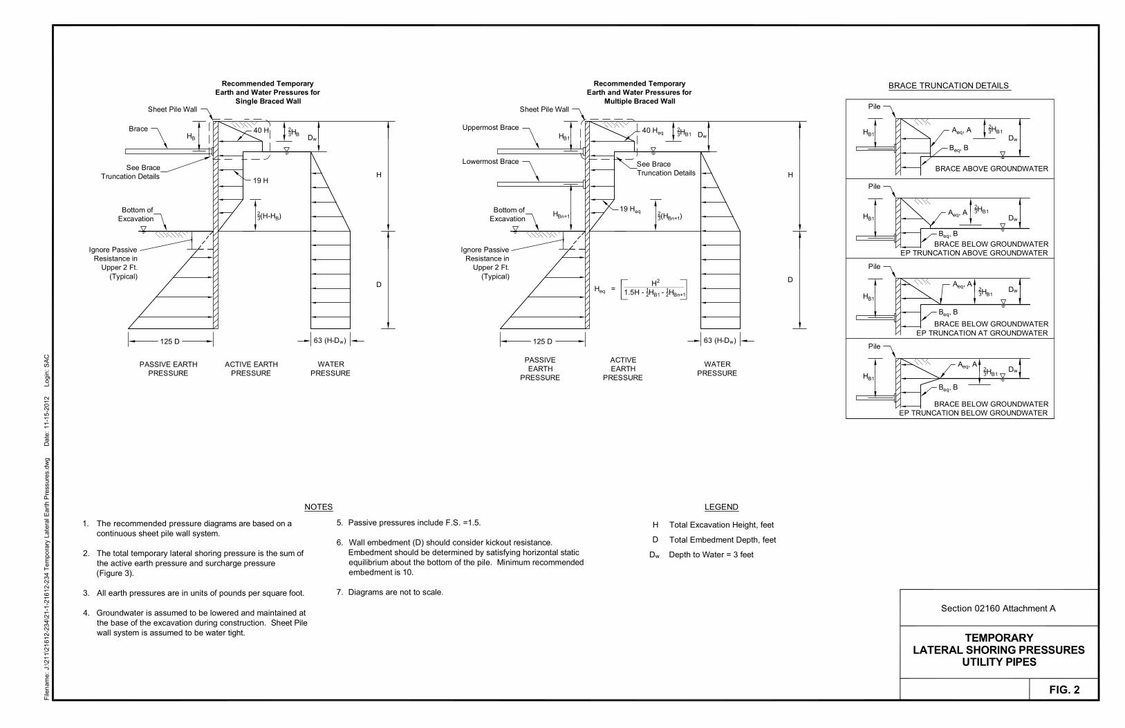
File
nam
e: J
:\21
1\21
612-
234\
21-1
-216
12-2
34 T
empo
rary
Lat
eral
Ear
th P
ress
ures
.dw
g
D
ate:
11-
15-2
012
Logi
n: S
AC
TEMPORARYLATERAL SHORING PRESSURES
UTILITY PIPES
FIG. 2
Section 02160 Attachment A
LEGEND
Total Excavation Height, feet
Total Embedment Depth, feet
Depth to Water = 3 feet
H
D
Dw
The recommended pressure diagrams are based on acontinuous sheet pile wall system.
The total temporary lateral shoring pressure is the sum ofthe active earth pressure and surcharge pressure(Figure 3).
All earth pressures are in units of pounds per square foot.
Groundwater is assumed to be lowered and maintained atthe base of the excavation during construction. Sheet Pilewall system is assumed to be water tight.
1.
2.
3.
4.
Passive pressures include F.S. =1.5.
Wall embedment (D) should consider kickout resistance.Embedment should be determined by satisfying horizontal staticequilibrium about the bottom of the pile. Minimum recommendedembedment is 10.
Diagrams are not to scale.
5.
6.
7.
NOTES
Recommended TemporaryEarth and Water Pressures for
Single Braced WallSheet Pile Wall
Ignore PassiveResistance in
Upper 2 Ft.(Typical)
PASSIVE EARTHPRESSURE
Bottom ofExcavation
HB
23HB
ACTIVE EARTHPRESSURE
23(H-HB)
Dw
H
Brace
WATERPRESSURE
125 D
Recommended TemporaryEarth and Water Pressures for
Multiple Braced WallSheet Pile Wall
Bottom ofExcavation
HB1
HBn+1
23HB1
ACTIVEEARTH
PRESSURE
Dw
Uppermost Brace
Lowermost Brace
WATERPRESSURE
H2
1.5H - 12HB1 - 12HBn+1
Heq =
40 Heq
19 Heq
40 H
19 H
23(HBn+1)
H
Pile
HB1
23HB1
Dw
Pile
HB1
23HB1
Dw
Pile
HB1
BRACE BELOW GROUNDWATEREP TRUNCATION AT GROUNDWATER
23HB1
Dw
BRACE BELOW GROUNDWATEREP TRUNCATION BELOW GROUNDWATER
BRACE ABOVE GROUNDWATER
BRACE TRUNCATION DETAILS
Pile
HB1
BRACE BELOW GROUNDWATEREP TRUNCATION ABOVE GROUNDWATER
23HB1
Dw
Aeq, A
Ignore PassiveResistance in
Upper 2 Ft.(Typical)
PASSIVEEARTH
PRESSURE
125 D
See BraceTruncation Details
See BraceTruncation Details
Aeq, A
Aeq, A
Aeq, A
Beq, B
Beq, B
Beq, B
Beq, B
DD
63 (H-Dw)63 (H-Dw)

SURCHARGE LOADINGFOR SHORING
FIG. 3
File
: J:
\211
\216
12-
234\
21-1
-216
12-2
34 S
urch
arge
Loa
ding
.dw
g
D
ate:
11-
15-2
012
A
utho
r: S
AC
Wal
l
PLAN VIEW
H
HH
2.0B
) (psf) cos (1.1' = 2
1.5B
Dep
th, Z
1.0B
0.0B
0.5B
Wal
l
Z
Wall Line
= H p s
L/B =
L/B = 0.25
L/B = 0.5L/B = 1
UNIFORM SURCHARGE
H s = (0.4)q
H = q2
< 15 FeetH
EARTH BERM
(psf)s q
2
(0.4) (H ) s
Note: < 33°
H
H
z=nH
Bottom ofExcavation
x = mH Q
Point Loadin Pounds
(psf)H
ELEVATION VIEW
x = mH
H
Bottom ofExcavation
Wal
l
z=nH
(psf)H
Line Load inPounds/Foot
lQ
B) LATERAL PRESSURE DUE TO LINE LOAD i.e. NARROW CONTINUOUS FOOTING PARALLEL TO WALL
C) LATERAL PRESSURE DUE TO STRIP LOAD
( - sin cos2) (psf)
Wal
l
Wal
l
s
Wal
l
A) LATERAL PRESSURE DUE TO POINT LOAD i.e. SMALL ISOLATED FOOTING OR WHEEL LOAD
D) LATERAL PRESSURE DUE TO EARTH BERM OR UNIFORM SURCHARGE
Bottom ofExcavation
Bottom ofExcavation
E) LATERAL PRESSURE DUE TO ADJACENT FOOTING
0 0.5 1.0
q
L
B
NOTES
Figures are not drawn to scale.
Applicable surcharge pressures should beadded to appropriate temporary andpermanent wall pressures.
If point or line loads are close to the back ofthe wall such that m 0.4, it may be moreappropriate to model the actual loaddistribution (i.e., Detail E) or use morerigorous analysis methods.
Wal
l
BearingPressureq (psf)
1.
2.
3.
=
I , Influence Factor
(I ) q
p
Lateral FootingPressure on Wall
(derived from NAVFAC DM 7.2,1986; and Sandhu, Earth Pressureon Walls Due to Surcharge , 1974)
(derived from Poulos and Davis, Elastic Solutions forSoil and Rock Mechanics , 1974; and Terzaghi and
Peck, Soil Mechanics in Engineering Practice , 1967)
(NAVFAC DM 7.2, 1986)
(derived from Fang, FoundationEngineering Handbook , 1991)
(NAVFAC DM 7.2, 1986)
= 1.28 (psf)H
H
2m nlQ
(m + n )H 2 2 2
(0.16 + n )lQ
Hn
2 2 = 0.20 (psf) (see Note 3) For m < 0.4:
For m > 0.4: = 1.77 (psf)H
H
2m npQ
(m + n )H 2 2 3
(0.16 + n )pQ
H
2n2
= 0.28 (psf) (see Note 3) For m < 0.4:
For m > 0.4: 2
p
Point Loadin Pounds
= Unit Weight of Earth Berm
s
Qp
BearingPressure
EarthBerm
2
2
H
H'
= Lateral PressureH
H'
in radians
ELEVATION VIEW
s
3
(see Note 3) (see Note 3)
Section 02160 Attachment A

This page intentionally left blank.

August 2017 C01072C17 Georgetown Wet Weather Treatment Station 02200 - 1 EARTHWORK
SECTION 02200
EARTHWORK
PART 1 GENERAL
1.01 SUMMARY
A. This Section specifies earthwork which consists of excavation, materials, backfilling, compacting, grading and testing. It applies to all portions of the contract except the Marine Outfall, which is covered by Section 02323.
1.02 QUALITY ASSURANCE
A. Referenced Standards: This Section incorporates by reference the latest revision of the following document. These references are a part of this Section as specified and modified. In case of conflict between the requirements of this Section and those of the listed documents, the requirements of this Section shall prevail. Reference Title Seattle Standard Specifications
City of Seattle Standard Specifications for Road, Bridge and Municipal Construction (2017 Edition)
ASTM C131 Standard Test Method for Resistance to Degradation of Small-Size Coarse Aggregate by Abrasion and Impact in the Los Angeles Machine
ASTM C136 Standard Test Method for Sieve Analysis of Fine and Coarse Aggregates
ASTM C535 Standard Test Method for Resistance to Degradation of Large-Size Coarse Aggregate by Abrasion and Impact in the Los Angeles Machine
ASTM D1556 Standard Test Method for Density and Unit Weight of Soil in Place by the Sand-Cone Method
ASTM D1557 Standard Test Method for Laboratory Compaction Characteristics of Soil Using Modified Effort (56,000 ft-lbf/ft3 (2,700 kN-m/m3))
ASTM D2216 Standard Test Method for Laboratory Determination of Water (Moisture Content of Soil and Rock by Mass)
ASTM D2922 Standard Test Method for Density of Soil and Soil-Aggregate in Place by Nuclear Methods (Shallow Depth)
ASTM D3017 Standard Test Method for Water Content of Soil and Rock in Place by Nuclear Methods (Shallow Depth)
ASTM D6913 Standard Test Methods for Particle-Size Distribution (Gradation) of Soils Using Sieve Analysis
ASTM E329 Standard Specification for Agencies Engaged in the Testing and/or Inspection of Materials Used in Construction
WAC 173-303-090 Dangerous Waste Characteristics WAC 173-303-110 Sampling and testing methods and analyses
B. See Seattle Standard Specifications for quality control requirements including the following: 1. Subgrade inspection after excavation per Seattle Standard Specifications Sections 2-04.3(1) and
2-09.3(1).
1.03 SUBMITTALS
A. Procedures: Section 01300.
B. Samples per this Section.

August 2017 C01072C17 Georgetown Wet Weather Treatment Station 02200 - 2 EARTHWORK
C. Laboratory test reports and samples of fill materials to be used, certifying: 1. Moisture density relationships and gradation test reports and curves. 2. Gradation tests for non-cohesive materials. 3. Any other requirements of the material as described in this Section.
D. Date, location, elevation, and results of on-site density measurements (compaction tests).
E. See Seattle Standard Specifications for material submittal requirements including the following: 1. Submit all applicable documents required under Seattle Standard Specifications Section 1-05.3
prior to construction. A material source form of all materials to be placed in the Seattle and WSDOT right of way and mix designs for all asphalt, concrete, and aggregates to be placed in the Seattle and WSDOT rights of way shall be submitted to the Seattle Department of Transportation and Project Representative for review and approval prior to beginning construction.
2. A revised material source form and mix designs shall be submitted for review and approval prior to placement of any substitute materials.
3. Test reports for required testing per Seattle Standard Specifications. 4. Aggregate source approval per Seattle Standard Specifications Section 9-03.0. 5. Sources of borrow material, borrow site, and borrow material per Seattle Standard Specifications
Section 2-10.2(2)A. 6. Controlled Density Fill Manufacturer’s Certificate of Compliance per Seattle Standard
Specifications Section 2-10.2(3)A4. 7. Certifications for recycled materials per Seattle Standard Specifications Section 9-03.18.
1.04 DEFINITIONS
A. Compaction: The degree of compaction is specified as percent compaction. Maximum or relative densities refer to dry soil densities obtainable at optimum moisture content in accordance with ASTM D1557.
B. Earthwork or Excavation: includes all materials excavated or removed regardless of material characteristics.
C. Excavation slope: An inclined surface formed by removing material from below existing grade.
D. Embankment slope: An inclined surface formed by placement of material above existing grade.
E. Imported backfill: Select material which meets the Fill Class specified and is obtained from a supplier regularly engaged in the business of supplying soil and fill material. It is not material which is obtained from on-site excavation.
F. Native soil: Materials excavated from within the Contract limits.
G. Select Native Material: Native soil which meets the specifications of a specified Fill Class.
H. Suspect Material: Any material in the excavation which is potentially contaminated based on visual observation or odor; includes soils, water or foreign material found within the excavation limits.
I. Dust Ratio: Percent of material passing the No. 200 sieve divided by the percent of material passing the No. 40 sieve.
1.05 SAMPLES
A. Samples of imported and native fill materials to be used 30 days in advance of use.
B. Samples shall consist of 0.5 cubic feet of each type of material.

August 2017 C01072C17 Georgetown Wet Weather Treatment Station 02200 - 3 EARTHWORK
C. Deliver to location provided by Project Representative.
1.06 TESTING
A. Obtain services of a qualified independent testing laboratory per ASTM E329 to perform quality control tests and to document compliance with Contract requirements during the Work.
B. Prior to placement, submit samples of materials to be used to the qualified testing laboratory.
C. Tests will be made in accordance with ASTM E329 and in accordance with the following: Test Standard Procedure
Moisture content ASTM D3017, ASTM D2216 Gradation ASTM C136, ASTM D6913 Density in-place ASTM D1556 Moisture-density relationships ASTM D1557
D. Laboratory test reports of imported and native fill materials that show the suitability of the material and certifying: 1. Moisture density relationships and gradation test reports and13 curves. 2. Gradation tests for non-cohesive materials. 3. Any other requirements of the material as described in this Section. 4. Per WAC 173-303-090 - Dangerous Waste Characteristics. 5. Per WAC 173-303-110 - Sampling and testing methods and analyses.
E. Laboratory test reports of native materials at a minimum of every 200 cubic yards of material placed. Sampling and testing of imported materials at a minimum of every 400 cubic yards of material placed.
F. County may take samples and perform moisture content, gradation, and density tests to check compliance with the Contract. Provide assistance to the County to facilitate this testing. See Section 01410. 1. Remove material at locations designated by the Project Representative and provide sampling and
testing assistance for compliance. Backfill and compact excavation and restore surface after testing.
2. Project Representative may request that the Contractor construct trenches for inspection in compacted or consolidated backfill to determine per ASTM D2922 that the Contractor has complied with the Specifications.
3. Testing by the Project Representative does not relieve the Contractor of its responsibility to document that the Work meets the Specifications.
1.07 TEST METHODS FOR AGGREGATES
A. Per Seattle Standard Specifications Section 9-03.15.
PART 2 PRODUCTS
2.01 MATERIALS
A. Backfill: 1. Selected Material: Seattle Standard Specifications Section 2-10.2(1). 2. Unclassified Borrow: Seattle Standard Specifications Section 2-10.2(2).
B. Controlled Density Fill 1. Select and proportion ingredients to obtain:
a. Material that is flowable.

August 2017 C01072C17 Georgetown Wet Weather Treatment Station 02200 - 4 EARTHWORK
b. Compressive strength between 8 psi and 100 psi at 28 days in accordance with ASTM D4832.
2. Materials: a. Cement: ASTM C150/C150M, Type I or Type II. b. Aggregate: ASTM C33/C33M, Size 7. c. Fly Ash (Pozzolan): Class F or Class C fly ash in accordance with ASTM C618, except as
modified herein: 1) ASTM C618, Table 1, Loss on Ignition: Unless permitted otherwise, maximum 3 percent.
d. Water: Clean, potable, containing less than 500 ppm of chlorides. e. Admixtures as needed for flowability and set.
C. Mineral Aggregate Type 2G, 1-1/4” Minus Crushed Gravel: Seattle Standard Specifications Section 9-03.16.
D. Mineral Aggregate Type 13, 2-1/2” Minus Crushed Rock: Seattle Standard Specifications Section 9-03.16
E. Mineral Aggregate Type 15, Pit Run Sandy Gravel: Seattle Standard Specifications Section 9-03.16.
F. Mineral Aggregate Type 17, Bank Run Gravel: Seattle Standard Specifications Section 9-03.16.
G. Mineral Aggregate Type 26, ¾” Washed Sandy Gravel: Seattle Standard Specifications Section 9-03.16.
H. Sand Drain Backfill: Seattle Standard Specifications Section 9-03.13(1).
I. Structure Backfill: Seattle Standard Specifications Section 2-10.3(4).
J. Native material not meeting the Specifications cannot be used and imported material shall be used.
K. Construction Geotextile for Underground Drainage: 1. Meeting the requirements of City of Seattle Standard Specifications Sections 2-15 and 9-37,
Class C, moderate survivability Geotextile for Underground Drainage except that water permittivity shall be 1 sec-1 minimum and the material must be nonwoven.
L. Recycled Material: 1. Recycled materials may be used as a replacement for specified materials to the extent and with
the certification requirements as provided in City of Seattle Standard Specifications Section 9-03.1
M. Marking Utility Warning Tape 1. Magnetic tracer tape for use with non-metallic pipe shall be two inches wide, colored green for
sanitary sewer, blue for potable water, or other labeling as needed. Tape shall be suitable for direct burial.
2. Plastic tracer tape for use with metallic pipe shall be 4 mil, three inches wide and colored green for sanitary sewer, blue for potable water, or other labeling as needed. Tape shall be suitable for direct burial.
3. A message shall be printed on the tape: a. The message shall read "CAUTION ____________ PIPE BURIED BELOW" with bold letters
approximately 2 inches high for tracer tape and approximately 1-1/4 inches high for magnetic tracer tape.
b. The blank shall be filled with the name of particular system fluid. c. The message shall be printed at maximum intervals of 2 feet.

August 2017 C01072C17 Georgetown Wet Weather Treatment Station 02200 - 5 EARTHWORK
PART 3 EXECUTION
3.01 GENERAL
A. Earthwork shall be per Seattle Standard Specifications. Backfill per Seattle Standard Specifications Section 2-10.3: 1. Structure Backfill per Seattle Standard Specifications Section 2-10.3(4):
a. Class A or Class B per Seattle Standard Specifications Section 9-03.12(1). 2. Controlled Density Fill per Seattle Standard Specifications Section 2-10.3(7).
B. Fill material shall be placed in horizontal layers and compacted with power operated tampers, rollers, idlers, or vibratory equipment.
C. Extra excavation (Over-excavation): 1. Where the undisturbed condition of natural soils is inadequate for support of the planned
construction as determined by the Project Representative, over excavate to adequate supporting soils.
2. Fill the excavated space to the specified elevation. 3. Unless otherwise indicated, the over excavated space under trenches, footings and structures
shall be backfilled with Mineral Aggregate Type 13 in combination with a Geotextile for Underground Drainage to separate the material from native soils.
D. Control of water: 1. Keep excavations free from water during construction. 2. Draw down the static water level a minimum of two feet below the bottom of excavations to
maintain the undisturbed state of natural soils and allow the placement of pipe and fill materials. 3. Disposal of water: Section 02271.
E. Monitoring for suspect materials, contaminated soils, and cultural resources: 1. Monitor excavation by observation and smell for suspect materials including potentially
contaminated soil, water or foreign substances as specified in Section 02060. If suspect material is detected, follow the requirements in Section 01560 and Section 02060.
2. Monitor excavation by observation for cultural resources as defined in Section 01560. If potential cultural resources are uncovered, immediately notify the Project Representative.
F. Excavated material: 1. Unless otherwise indicated, excess excavated material (fill) shall be disposed of off-site in
accordance with Section 01560. 2. Select structural fill removed for structural excavation, or final grading or paving, shall be
stockpiled outside of the existing structurally filled area. 3. Material shall not be stockpiled on the existing structurally filled area. In addition, material shall
not be stockpiled to a depth greater than five feet above foundation grade or within 25 feet of any excavation or structure.
4. Use construction methods that preserve the stability of the soil adjacent to the excavation. 5. Protect stockpiled materials from wind or rain erosion and water saturation by covering with tarps
or other effective methods.
G. Finish grading: 1. Finished surfaces shall be smooth, compacted, and free from irregularities. 2. Finished grade shall be as specified by the contours +0.10-foot, except where a local change in
elevation is required to match sidewalks, curbs, manholes, and catch basins, or to ensure proper drainage.
3. When the Work is in an intermediate stage of completion, the lines and grades shall be as specified +0.5-foot to provide adequate drainage.
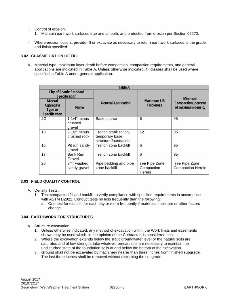
August 2017 C01072C17 Georgetown Wet Weather Treatment Station 02200 - 6 EARTHWORK
H. Control of erosion: 1. Maintain earthwork surfaces true and smooth, and protected from erosion per Section 02270.
I. Where erosion occurs, provide fill or excavate as necessary to return earthwork surfaces to the grade and finish specified.
3.02 CLASSIFICATION OF FILL
A. Material type, maximum layer depth before compaction, compaction requirements, and general applications are indicated in Table A. Unless otherwise indicated, fill classes shall be used where specified in Table A under general application.
Table A
City of Seattle Standard Specification
General Application Maximum Lift Thickness
Minimum Compaction, percent of maximum density
Mineral Aggregate
Type or Specification
Name
2G 1-1/4" minus crushed gravel
Base course 6 95
13 2-1/2" minus crushed rock
Trench stabilization, temporary base, structure foundation
12 95
15 Pit run sandy gravel
Trench zone backfill 6 95
17 Bank Run Gravel
Trench zone backfill 6 95
26 3/4" washed sandy gravel
Pipe bedding and pipe zone backfill
see Pipe Zone Compaction Herein
see Pipe Zone Compaction Herein
3.03 FIELD QUALITY CONTROL
A. Density Tests: 1. Test compacted fill and backfill to verify compliance with specified requirements in accordance
with ASTM D2922. Conduct tests no less frequently than the following: a. One test for each lift for each day or more frequently if materials, moisture or other factors
change.
3.04 EARTHWORK FOR STRUCTURES
A. Structure excavation: 1. Unless otherwise indicated, any method of excavation within the Work limits and easements
shown may be used which, in the opinion of the Contractor, is considered best. 2. Where the excavation extends below the static groundwater level or the natural soils are
saturated and of low strength, take whatever precautions are necessary to maintain the undisturbed state of the foundation soils at and below the bottom of the excavation.
3. Ground shall not be excavated by machinery nearer than three inches from finished subgrade. The last three inches shall be removed without disturbing the subgrade.
August 2017 C01072C17 Georgetown Wet Weather Treatment Station 02200 - 7 EARTHWORK
4. The bottom shall not be more than 0.15-foot above or below the lines and grades specified. If the elevation of structure excavation is not specified, the excavation shall be not more than 0.15-foot above or below the elevation specified for fill material below the structure. Sloped excavation bottoms shall vary no more than 0.5-foot from specified grade unless the excavation is in rock where the maximum variation shall be two feet.
5. Should the excavation be carried below the lines and grades indicated in the Drawings or should the bottom of the excavation be disturbed because of the Contractor's operations and require over-excavation and backfill, refill such excavated space to the proper elevation in accordance with the procedure specified for backfill.
6. Unless otherwise indicated, excavations shall extend a sufficient distance from walls and footings to allow for placing and removal of forms, and installation of services, except where concrete is specified to be placed directly against excavated surfaces or shoring.
B. Structure backfill: 1. After completion of construction below the elevation of the final grade, and prior to backfilling,
concrete forms shall be removed (unless specified otherwise) and the excavation shall be cleaned of debris.
2. Do not place backfill until the subgrade portions of the structure have been inspected by the Project Representative.
3. No backfill material shall be deposited against concrete structures until the concrete has been in place for 28 days or until the concrete has developed a strength of not less than allowed by Local Authority Having Jurisdiction, whichever occurs first.
4. Backfill material shall be placed in uniform layers and shall be brought up uniformly on all sides of the structure.
5. Accomplish compaction by using power-operated tampers, rollers, or vibratory equipment. Perform compaction within two feet of walls with hand-operated vibratory compactors.
6. Unless otherwise indicated, backfill around and above pipelines within the excavation line of any structure shall be the same as that specified for structures.
7. If there is a void between the shoring and the formwork for the wall construction, fill the void with CDF or a flowable grout approved by the Project Representative.
3.05 TRENCHING
A. Excavation shall be per Seattle Standard Specifications Sections 2-04.1 and 2-04.3.
B. Remove all ledge rock, boulders, and stones 4 inches and larger to provide a minimum clearance of 12 inches under and around the pipe or duct bank.
C. In loose or soft soils, perform the excavation at the bottom of the trench using equipment that does not have digging teeth. Should the natural or fill foundation soils at the trench bottom be disturbed or loosened because of the Contractor's operations, re-compact or remove. If material is removed, refill the area with foundation material as specified in Section 02200 and as indicated in the Drawings.
D. Excavate all trenches in accordance with the lines and grades indicated in the Drawings. Typical trench sections with maximum and minimum dimensions are indicated in the Drawings.
E. Monitoring for suspect materials, contaminated soils, and cultural resources: 1. Monitor excavation by observation and smell for suspect materials including potentially
contaminated soil, water or foreign substances. If suspect material is detected, follow the requirements in Section 01560 and Section 02060.
2. Monitor excavation by observation for cultural resources as defined in Section 01560. If potential cultural resources are uncovered, immediately notify the Project Representative.
F. Existing Utilities: Section 01195.

August 2017 C01072C17 Georgetown Wet Weather Treatment Station 02200 - 8 EARTHWORK
G. UPRR railroad tracks: 1. Comply with UPRR requirements at railroad tracks.
3.06 PIPE FOUNDATIONS
A. Foundation Preparation: 1. Properly prepare the foundation and place the foundation material prior to installation of pipe
bedding and pipe. 2. Prepare the native trench bottom and/or the top of the foundation material to a uniform grade so
that the entire length of pipe rests firmly on a properly compacted pipe bedding material. 3. Place bedding and backfill material around the pipe in a manner to meet requirements specified
in the respective section for the type of pipe for the type of pipe being installed.
B. Inadequate Soils: 1. Where the undisturbed condition of the natural soil material is inadequate for support of the
planned pipeline, notify the Project Representative who will direct the Contractor on how to proceed.
2. Backfill the excavated space to the specified grade in accordance with Section 02200. 3. Should the excavation be carried below the lines and grades indicated in the Drawings because
of the Contractor's operations, refill such excavated space to the proper elevation.
3.07 PIPE BEDDING
A. Placement of bedding material in the pipe zone shall be as indicated in the Drawings or, if not indicated, as specified in Section 02200.
3.08 MARKING TAPE
A. Install at a distance two feet above buried utility or as detailed in the Drawings.
3.09 BACKFILLING
A. Backfill in accordance with Seattle Standard Specifications Sections 2-10.3 and 7-17.3(3).
B. Complete pipe bedding and initial backfill as indicated in the Drawings before subsequent backfilling operations are started. Do not allow the pipe to float in the backfill.
C. Take necessary precautions to protect the pipe from damage, movement or shifting. In general, perform backfilling by placing the material so as avoid damage to the pipe.
D. Trenches shall be completely backfilled as soon after the pipe laying as possible. Unless specifically authorized in writing by the Project Representative, no portion of temporary excavation support shall be left in the excavation.
E. Keep pipe placed below the water table from floating by lowering the water level in accordance with Section 02140.
F. Excess material shall be disposed of as required by Sections 01560 and 02200.
G. Pipe zone backfill shall be placed in loose layers and compacted.
H. Backfill shall be brought up simultaneously on each side of the pipe to the top of the pipe zone.
I. Cover pipe to the top of the pipe zone and compact materials in a manner to avoid damaging or disturbing the completed pipe.

August 2017 C01072C17 Georgetown Wet Weather Treatment Station 02200 - 9 EARTHWORK
J. Above the pipe zone, backfill and compact in accordance with the requirements of Table A.
K. Do not operate tractors or other heavy equipment over the top of the pipe until the backfill has reached a height above the top of the pipe suitable to protect the pipe from construction loads.
L. UPRR railroad tracks: 1. Comply with UPRR requirements at railroad tracks.
3.10 PIPE ZONE COMPACTION
A. Compaction per Seattle Standard Specifications Sections 2-11.3(1): Method B.
B. Equipment: 1. Provide the proper size and type of compaction equipment and select the proper method of
utilizing said equipment to attain the required compaction density. 2. In all cases, select and use equipment that will not damage the pipe or other utilities and
structures. 3. Truck-mounted drop hammers or truck-mounted impact hammers, impact pavement breakers,
and similar types of mobile equipment are not permitted for compacting backfill placed around or above pipes.
C. Water settling methods of compaction are not permitted.
D. The County may perform in-place compaction tests to verify compaction. Remove and replace materials, and re-compact material that does not meet specified requirements.
3.11 FINISH GRADING
A. Areas covered by the Work, including excavated and filled sections and transition areas, shall be graded uniformly to the elevations and grades indicated in the Drawings within the specified tolerance.
B. Finished surface shall be reasonably smooth, compacted, and free from irregularities. The degree of finish shall be that normally obtainable with a blade-grader.
C. Finished surface shall be not more than 0.2 feet above or below the established grade.
D. Ditches shall be finished to drain readily.
E. The surface of areas to be paved on which a base course is to be placed shall not vary more than 0.05 feet from established grade and cross section.
F. In landscape areas where utility trenching or grading activities occurred, grade to the depth required below finished grade to allow placement of topsoil and mulch up to finished grade indicated in the Drawings.
3.12 DISPOSAL OF EXCAVATED MATERIAL
A. Unless otherwise indicated, excavated material shall be the property of the Contractor.
B. Be responsible for the removal and disposal of excess excavated material of all types.
C. Material shall be disposed of at a legal offsite disposal location.

August 2017 C01072C17 Georgetown Wet Weather Treatment Station 02200 - 10 EARTHWORK
3.13 GEOTEXTILES
A. Install as noted in City of Seattle Standard Specifications Section 2-15 and 7-01.3(2).
END OF SECTION

August 2017 C01072C17 Georgetown Wet Weather Treatment Station 02270 - 1 EROSION AND SEDIMENT CONTROL
SECTION 02270
EROSION AND SEDIMENT CONTROL
PART 1 GENERAL
1.01 SUMMARY
A. This Section specifies constructing and maintaining the surface water drainage and temporary erosion and sediment control system (TESC) as prepared in the Construction Stormwater Control Plan (CSC Plan).
B. This Section applies to upland construction and does not include provisions for in-water sediment controls. Environmental protection measures specific to in-water construction activities are specified in Sections 01561 and 02323.
1.02 QUALITY ASSURANCE
A. Referenced Standards: This Section incorporates by reference the latest revision of the following documents. These references are a part of this Section as specified and modified. In case of a conflict between the requirements of this Section and those of the listed documents, the requirements of the more stringent requirement shall prevail. Reference Title ASTM A392 Zinc-Coated Steel Chain-Link Fence Fabric ASTM D586 Test Method For Ash In Pulp, Paper, And Paper Products ASTM D882 Test Method for Tensile Properties of Thin Plastic Sheeting ASTM D1004 Test Method for Initial Tear Resistance of Plastic Film and Sheeting ASTM D1388 Test Method for Stiffness of Fabrics ASTM D1777 Test method for Thickness of Textile Materials ASTM D3776 Test method for Mass per Unit Area (Weight) of Fabric ASTM D3786 Test Method for Hydraulic Bursting Strength of Textile Fabrics-
Diaphragm Bursting Strength Tester Method ASTM D4355 Test Method for Deterioration of Geotextiles by Exposure to Light,
Moisture and Heat in a Xenon Arc Type Apparatus ASTM D4491 Test Methods for Water Permeability of Geotextiles by Permittivity ASTM D4632 Test Method for Grab Breaking Load and Elongation of Geotextiles ASTM D4751 Test Method for Determining Apparent Opening Size of a Geotextile ASTM D4833 Test Method for Index Puncture Resistance of Geotextiles,
Geomembranes, and Related Products ASTM F405 Corrugated Polyethylene (PE) Tubing and Fittings AASHTO M252 Corrugated Polyethylene Drainage Pipe, Nominal Sizes of 3 Inches
to 10 Inches in Diameter RCW 90.48 Water Pollution Control SMMWW Washington Department of Ecology (Ecology), Stormwater
Management Manual for Western Washington SMC Title 22.800 Seattle Municipal Code: Stormwater Code SSM V.2 Seattle Stormwater Manual Volume 2: Construction Stormwater
Control Technical Requirements Manual KCSWDM King County Surface Water Design Manual, 2009 Edition
August 2017 C01072C17 Georgetown Wet Weather Treatment Station 02270 - 2 EROSION AND SEDIMENT CONTROL
B. Conform to the applicable requirements of RCW 90.48, SMMWW, SMC 22.800, and SSM V.2.
C. If there is a conflict between the specifications and listed codes/regulations, the more stringent requirements shall prevail.
D. Conform to the requirements of the permits listed in Section 01062.
E. Qualifications: 1. Certified Erosion and Sediment Control Lead (CESCL): Active certification through a CESCL
course approved by Ecology.
1.03 SUBMITTALS
A. Procedures: Section 01300.
B. Qualifications.
C. Construction Stormwater Control Plan.
D. Product Data.
1.04 DEFINITIONS
A. Dry Season: See Section 01014.
B. Wet Season: See Section 01014.
C. Process Water: 1. Process water discharges include, but are not limited to: truck wash water, tire bath wastewater,
wheel wash water, and equipment wash water. 2. Water which, during manufacturing or processing, comes into direct contact with or results from
the production or use of any raw material, intermediate product, finished product, byproduct, or waste product.
3. Water that comes in contact with uncured concrete.
1.05 CONSTRUCTION STORMWATER CONTROL PLAN (HEREINAFTER “THE CSC PLAN”)
A. Consists of Best Management Practices (BMPs) that control erosion and sedimentation from the Contractor’s activities and treats stormwater to meet discharge requirements.
B. Submit a Construction Stormwater Control Plan with Drawings prior to commencement of work. 1. Indicate the minimum requirements at the start of work. 2. During the construction period, the BMPs shall be upgraded and modified as needed to meet
discharge requirements for changing construction activities, storm events, and changing site conditions.
3. Maintain a copy of the current CSC Plan in the Environmental Mitigation Plan per Section 01560 on Site at all times.
4. This CSC shall include information to adequately address the requirements for a Temporary Sediment and Erosion Control Plan (TESC Plan) references in relevant permits.
C. Schedule BMP implementation correlated to wet and dry season activities. This may include activities such as temporary seeding and permanent seeding activities that change with the seasons.
D. Provide at a minimum, the following information: 1. All requirements in the Drawings and Specifications.

August 2017 C01072C17 Georgetown Wet Weather Treatment Station 02270 - 3 EROSION AND SEDIMENT CONTROL
2. Locations and construction details of all proposed TESC BMPs including (at a minimum): a. Silt fences. b. Clearing limits fences. c. Stabilized construction entrance(s). d. Temporary diversion systems. e. Temporary bypassing of existing stormwater outfall that serves north side of First Avenue
Bridge (SR-99) around trench sheeting work area. f. Check dams. g. Inlet protection. h. Pipe slope drains. i. Sediment ponds. j. Sediment traps, including those along downstream edges of work area to intercept and detain
sediment under sheet flow conditions. k. Temporary stormwater application systems. l. Ditches. m. Berms. n. Culvert Pipes. o. Filter systems. p. Outfalls and outlet protection. q. Erosion control seeding. r. Stockpile cover and temporary bare soil cover. s. Slope protection.
3. Locations, types, and quantities of all plantings, slope coverings, and ditch liners. 4. Show necessary rerouting of existing surface water and underground drainage within the Site to
erosion control facilities prior to release to the offsite drainage systems. 5. Location of cut and fill slopes. 6. Approximate slopes, contours, and direction of stormwater flow before and after major grading
activities. 7. Location of off-site material, stockpiles, waste storage, borrow areas, and vehicle/equipment
storage areas. 8. Location of all surface water bodies, including wetlands, ponds, lakes, streams, and drainage
ditches. 9. Location of water quality sampling stations. 10. Maintenance schedule of TESC. 11. Include in the CSC Plan measures to prevent the addition of Process Water or domestic
wastewater into the stormwater.
PART 2 PRODUCTS
2.01 MATERIALS
A. Quarry Spalls: per Section 02323 except gradation shall be 4 to 8 inches free of fines, soil and other extraneous materials.
B. Reinforced plastic fabric: 1. Construed, copolymer laminate. 2. Reinforcing: Non-woven grid of high strength nylon cord submerged in a permanently flexible
adhesive medium. 3. Equal tear resistance in all directions. 4. Ultraviolet light stabilized. 5. Material to be from a single manufacturer. 6. Physical strength requirements:
a. Tear strength, Ibs: 130 per ASTM D1004. b. Elongation percent: 620 per ASTM D882. c. Minimum life expectancy: 2-1/2 years of normal outdoor exposure.

August 2017 C01072C17 Georgetown Wet Weather Treatment Station 02270 - 4 EROSION AND SEDIMENT CONTROL
C. Geotextile fabric: 1. Stabilized construction entrance geotextile fabric shall meet the following:
Geotextile Property Text Method Survivability AOS sieve ASTM D4751 20-45 (U.S. standard
sieve size) Grab Tensile Strength ASTM D4632 200 lbs Grab Tensile Elongation ASTM D4632 30% max. Mullen Burst Strength ASTM D3786 400 psi min.
2. Temporary silt fence geotextile fabric shall meet the following:
Geotextile Property Test Method Posts with Wire or Polymeric Mesh
AOS slit ASTM D4751 0.60 mm max. for film wovens (#30 sieve). 0.30 mm max. for all other geotextile. 0.15 mm min. (#100 sieve).
Water permittivity ASTM D4491 0.02 sec-1 min. Grab Tensile Strength ASTM D4632 100 lbs. min. Ultraviolet (UV) Radiation Stability
ASTM D4355 70% strength retained min., after 500 hrs. in weather meter
D. Permanent re-vegetation mat: 1. Highly flexible polymeric mat with a three dimensional web-like weave. 2. Color: Green. 3. Biologically inert. 4. Acid and alkaline resistant. 5. Ultraviolet degradation resistant. 6. Physical properties:
a. Porosity: 85% TO 95%. b. Flexibility: 2000 mg/cm ASTM D1388. c. Weight: 18 oz/sy ASTM D3776. d. Thickness: 0.12-inch ASTM D1777. e. Tensile strength: Length 15 Ibs, width 5 lbs. f. Elongation: Length 150%, width 100%.
E. Erosion control blankets: 1. Biodegradable wood materials. 2. No chemical additives. 3. Photo degradable extruded plastic netting top and bottom. 4. Smolder resistant. 5. Physical properties of blanket for slope protection:
a. Weight: 0.98 Ibs/sy. b. Netting: 1-inch x 2-inch.
6. Physical properties of blanket for channel protection: a. Weight: 1.0 lbs/sy. b. Netting: 5/8-inch x 3/4-inch.
F. Straw: Tie bales with twine, with no excessive quantities of manure, seed of obnoxious weeds or other plant species.
G. Wire fabric for silt fence backing: 1. 2-inch x 2-inch or 2-inch x 4-inch with 14 ga. wire mesh. 2. Hot-dip galvanized, ASTM A392, Class 2.

August 2017 C01072C17 Georgetown Wet Weather Treatment Station 02270 - 5 EROSION AND SEDIMENT CONTROL
H. Sandbags: 1. Woven polypropylene fabric. 2. Fill Material:
a. Non-cohesive, class 1 or class 2 permeable material. b. Free from clay or deleterious material.
I. Perforated pipe: Polyethylene drainage tubing per ASTM F405 and AASHTO M252.
J. Pipe riser and barrel for detention basins: 1. 16 gage corrugated metal pipe (CMP), galvanized with perforations at 6-inch on center and a
maximum of ¾-inch diameter. 2. Provide bar screen consisting of ½-inch rebar at 4 inches on center, or equivalent screening
device approved by the project Representative.
K. Stone Filler: Section 02220, Class M fill.
L. Hydroseed Mulch: 1. Wood cellulose fiber mulch:
a. Fiber shall be produced from natural or recycled (pulp) fiber such as wood chips or similar wood materials, or from newsprint, corrugated cardboard, or a combination of these processed materials.
b. The fibers shall not contain any rock, metal, or plastic. 2. Treated with a nontoxic green dye non-toxic to plant or animal life to facilitate inspection of the
placement of the material. 3. Manufactured in such a manner that after addition and agitation in slurry tanks with water, the
fibers in the material will become uniformly suspended to form a homogenous slurry. 4. When hydraulically sprayed on the ground, the material shall allow the absorption and percolation
of moisture. 5. Contain less than 250 parts per million (ppm) boron and be non-toxic to plant and animal life. 6. Organic matter content shall be at least 90 percent on an oven-dry basis as determined by ASTM
D586. 7. Moisture content shall be no more than 15 percent as determined by oven dried weight.
M. Temporary and Permanent Seeding: Shall conform with the seeding standards in SSM V.2. 1. Temporary Erosion Control Seed Mix:
Name % Weight % Purity % Germination Turf type perennial rye (blend of three approved varieties from the Seattle Standard Specification 9-14.2(1)
50 98 90
Creeping Red Fescue 20 98 90 Chewings Fescue 20 98 90 Hard Fescue 20 98 90
N. Polyacrylamides (PAM) for soil erosion protection shall be consistent with BMP C126 in Chapter 4, Volume II SMMWW.
O. Catch Basin Inserts: 1. Prefabricated units specifically designed for storm inlet drainage protection. 2. Remain securely attached to the drainage structure when fully loaded with sediment and debris. 3. With retrieval straps attached. 4. With overflow ports in upper part of sediment accumulation bag.

August 2017 C01072C17 Georgetown Wet Weather Treatment Station 02270 - 6 EROSION AND SEDIMENT CONTROL
PART 3 EXECUTION
3.01 SEQUENCING AND SCHEDULING
A. Schedule or phase excavation to minimize impacts to critical habitat, mitigation areas, wetlands, streams and creeks.
B. Install perimeter protection (silt fence) prior to clearing and grubbing.
C. Complete CSC Plan and construct TESC BMPs prior to commencing trenching, cut and fill, or other earthwork activity.
3.02 PREPARATION
A. Prior to clearing, demolition below grade, excavation, and placement of fill; install clearing limits fences, perimeter silt fences, temporary stabilized construction entrance and perimeter control.
B. Prepare Site for surface water to flow away from excavations and disturbed soils.
C. Sediment control BMPs (sediment ponds, traps, diversion dikes, berms, etc) shall be constructed as a first step in grading. These BMPs shall be functional before other land disturbing activities take place.
D. The boundaries of the clearing/construction limits indicated on the Drawings shall be clearly marked in the field by a continuous length of high visibility fencing. 1. No disturbance beyond the clearing limits shall be permitted. 2. Maintain the clearing limit fencing for the duration of construction.
E. Protect catch basin inlets to drainage system from sediment influx by installing and maintaining inlet protection.
F. In preparation of paving, clean all catch basins and conveyance lines. The cleaning operation shall not flush sediment-laden water into the downstream system.
G. Prepare any permanent flow control facilities that will be used as a temporary settling basin with the necessary erosion control measures and provide adequate storage capacity.
H. Stockpile and restock as needed, at a minimum the following amounts of Erosion Control BMP materials and supplies on Site to be used during heavy storm events:
Material Measure Quantity Clear Plastic, 6 mil 100 foot 1 - 2 Drainpipe, 6 or 8 inch diameter 25 foot section 4 - 6 Sandbags, filled Each 25 - 50 Straw Bales for mulching, Approx. 50# each 10 - 20 Quarry Spalls Ton 2 - 4 Washed Gravel Cubic Yard 2 - 4 Geotextile Fabric 100 foot roll 1 - 2 Catch Basin Inserts Each 2 - 4 Steel “T” Posts Each 12 - 24
3.03 INSTALLATION
A. Catch Basin inserts: 1. Install at all locations indicated on the Drawings, CSC Plan, and where inspection deems
necessary. 2. Install according to manufacturer’s recommendations.

August 2017 C01072C17 Georgetown Wet Weather Treatment Station 02270 - 7 EROSION AND SEDIMENT CONTROL
3. Install in existing catch basins prior to any earth disturbing activity up hill of the catch basin. 4. Install in new catch basins prior to allowing any water to flow into the catch basin.
B. Seeding: 1. Hydroseed all disturbed areas following completion of construction of the TESC. 2. Seeding may be accomplished by approved hand methods when impracticable to do by
hydroseeding. 3. Review all disturbed areas prior to the beginning of the Wet Season to identify which ones can be
seeded in preparation for the Wet Season. 4. Disturbed areas shall be seeded within one week of the beginning of the Wet Season. 5. All areas to be seeded shall be cultivated to meet the local agency and Ecology requirements. 6. Cultivation may be accomplished by disking, raking, harrowing, or other acceptable means.
Perform all cultivating at right angles to the slope if necessary. 7. Install surface runoff control measures such as gradient terraces, interceptor dikes or swales,
level spreaders and sediment basins prior to seeding. 8. Fertilize: all areas which are seeded. 9. If hand seeding is allowed by the Project Representative, apply straw to all hand seeded areas. 10. Where straw mulch for TESC is required, it shall be applied at a thickness of two inches.
C. Pipe Slope Drains: 1. Install at all locations where storm water will be conveyed over cut or fill slopes or away from bare
soils to prevent gullies, channel erosion, and saturation of slide-prone soils. 2. Install diversion dikes or swales to collect and route water to the slope drain at the top of the
slope. 3. The soils around and under the pipe and entrance section shall be compacted to prevent
undercutting. 4. The pipe shall be secured to prevent movement. 5. The area below the outlet shall be stabilized with a riprap apron or energy dissipation structure.
D. Plastic sheeting: 1. Anchor in 2-foot x 2-foot trench around the entire perimeter of plastic sheeting. 2. Overlap joints with minimum two feet lap and tape seam. 3. Install hold downs at all excavation faces and at stockpiles. 4. Secure hold downs with polypropylene rope at ten feet on center, maximum each way, across the
entire surface of plastic sheeting. 5. Anchor the polypropylene rope by driving 2-inch x 4-inch stake at the top of excavations or
bottom of stockpiles and tying rope to stake.
E. Quarry Spalls: 1. Install at locations as indicated in the Drawings and CSC Plan.
F. Rock check dam: 1. Construct at locations indicated in the Drawings and according to the CSC Plan.
G. Sandbag check dams: 1. Install at all locations as indicated in the Drawings and at all locations required by the CSC Plan. 2. Stack sandbags at least 2-3 bags high and 1-2 bags thick. 3. Butt ends of bags tightly. 4. Overlap butt joints of row beneath with each successive row. 5. Leave a weir gap at the center of the check dam.
a. Ensure that the edges of the structure are at a higher elevation than the weir gap to prevent flow from escaping around the sides of the dam.
b. Place a sand bag(s) as a splash pad on the downstream side of the weir opening.
August 2017 C01072C17 Georgetown Wet Weather Treatment Station 02270 - 8 EROSION AND SEDIMENT CONTROL
H. Sandbag hold downs: 1. Secure with 1/4-inch polypropylene rope at ten feet on center maximum each way. 2. Anchor rope with 2-inch x 4-inch fir, standard or better.
I. Silt fence: 1. Install filter fabric over wire fabric. 2. Secure filter fabric to wire fabric:
a. Secure at top, middle, and bottom of each post. b. Wire fabric to extend to the top edge of the above ground filter fabric.
3. Use steel fence posts. a. Set posts at six foot on-center maximum.
4. Bury wire fabric in trench upslope and adjacent to the steel posts for the full length. 5. Bury bottom 8 inches of fabric in a 4x4 trench upslope. 6. Field joints:
a. Lap joints: 1) 2-foot minimum. 2) Remove all dirt, dust, moisture, and foreign materials. 3) Splice only at support posts with wire fabric.
b. Repairs: 1) Patch with filter fabric. 2) Extend lap six inches from damaged area in all directions. 3) Proceed as specified for joint.
c. Extend filter fabric 24 inches above the ground surface or greater.
J. Soils and Slopes: 1. If soil stockpiles (import or native) are placed on or along a street Right-of-Way, these shall be
covered with plastic at the end of each working day, use hold-downs where appropriate. 2. Any areas of exposed soils (i.e. excavated areas, spoil piles and imported or stored fill) that will
not be disturbed for two days during the wet season or seven days during the dry season shall utilize approved erosion control BMP methods to prevent turbid runoff into surface waters.
K. Stabilized Construction Entrance: 1. Install in accordance with the Drawings and at all locations vehicles access and exit the Site. 2. Constructed of Quarry Spalls placed to a minimum thickness of 12 inches. 3. Separation geotextile shall be placed under the Quarry Spalls to prevent fine sediment from
pumping into the rock pad. 4. Install driveway culvert if there is a roadside ditch present.
L. Temporary outlet protection (Energy Dissipation): 1. Install adequate energy dissipation and stabilization at the outlet of all surface water conveyance
systems. 2. Meet or exceed minimum design standard of the SSM BMP E2.85 – Outlet Protection.
M. Pipe riser and barrel for sediment basins: 1. Install in accordance with plan and erosion control standards. 2. Provide stone filter material at base of pipe riser. 3. Connect perforated drain pipe to pipe riser and barrel. 4. Connect to storm drain.
N. Stone filter for sediment basins: 1. Thickness of layer: 12 inches below pipe to 12 inches above pipe. 2. Width: 12 inches on each side minimum. 3. Do not run equipment on unprotected areas. 4. Do not damage perforated drain pipe. 5. One sieve analysis per 200 cu yd stone filter and rock check dam material placed. 6. Provide 2 ft of trap area below pipe penetrations for sediment storage.

August 2017 C01072C17 Georgetown Wet Weather Treatment Station 02270 - 9 EROSION AND SEDIMENT CONTROL
3.04 MAINTENANCE
A. Be responsible for the implementation of the CSC Plan, including all revisions, and the construction, inspection, maintenance, replacement, and modification of the TESC facilities.
B. Make revisions to the CSC Plan and perform the work necessary to meet the requirements of the SSM V.2 and SSM.
C. When a Site Erosion Control Inspection documents failing or inadequate BMPs, be responsible for implementing the following: 1. Correct the failing BMP within two calendar days. 2. If unanticipated site circumstances require installation of additional BMPs, the additional BMPs
shall be installed within ten calendar days. 3. Results of each inspection shall be documented at completion of the inspection.
a. Use Erosion Control Inspection Checklist form per the SMMWW. b. All installed Erosion Control BMPs shall be inspected each week in ensure proper
performance.
D. Assign only CESCL to conduct weekly Erosion Control Inspections.
E. When results of sampling required by Section 02271 demonstrate failing BMPs through exceedance of benchmark values, repair or install additional erosion control BMPs as required by the Construction Stormwater NPDES permit.
F. Prevent solids or turbid runoff from entering storm drains or local surface water bodies by utilizing appropriate source control BMPs.
G. Where erosion occurs, make modifications to the source control BMPs to eliminate the cause of the erosion then mitigate its affects.
H. General maintenance activities: 1. Inspect BMPs as required in this Section and by the permits. 2. Repair or replace damaged or missing items immediately. 3. Maintain seeded surfaces throughout construction.
I. Street Cleaning: See Section 01560.
J. Check Dams: 1. Remove accumulated sediments when the accumulated sediment depth reaches 6 inches or ¾ of
the height of the check dam, which ever is first. 2. Prevent sediments from being flushed to the downstream system during cleaning.
K. Silt fences: 1. Remove sediment from behind silt fences when deposits are 6 inches deep or greater. 2. Remove filter fabric where deteriorated. 3. Replace sections of filter fabric that have been torn or ripped.
L. Catch Basin Inserts: 1. Remove sediment and replace inserts when no longer providing filtration and through-flow
according to manufacturer’s recommendations.
M. Machine compact and track walk (perpendicular to the slope) slopes, berms, dikes, and embankments for sediment basins and traps.

August 2017 C01072C17 Georgetown Wet Weather Treatment Station 02270 - 10 EROSION AND SEDIMENT CONTROL
N. Be responsible for performing the required BMP maintenance as defined within Volume II of the SMMWW and within the SSM V.2.
O. Provide necessary ditches, swales, and dikes to collect and convey, in a non-erosive manner, stormwater runoff towards and into sediment basins.
P. Cover all areas that will be unworked for more than seven days during the dry season or two days during the wet season with straw, blankets, mats, wood fiber mulch, compost, plastic sheeting, or equivalent. 1. Seed or sod any areas to remain unworked for more than 30 days.
Q. Stabilize all areas within seven days of reaching final grade.
R. Check emergency spillways regularly to ensure that the lining is well established and erosion resistant.
3.05 COMPLETION OF CONSTRUCTION
A. TESC BMPs: 1. Shall be kept operational until the Site has undergone final stabilization (e.g., soils have been
stabilized by permanent measures, landscaping is installed, etc.) and through Substantial Completion of All Work.
2. Remove within 30 days after the Site has undergone final stabilization.
3.06 SYSTEM COMPLIANCE
A. The Project Representative and regulatory agencies will determine the effectiveness of the TESC.
B. Upgrade and modify TESC as required within five days of written Notice from the Project Representative until effective. Refusal to modify and upgrade the TESC may result in the work being completed by the Project Representative and the cost of the work being deducted from the Application for Payment.
C. Non-compliance with the erosion control requirements and water quality requirements may result in stoppage of work.
END OF SECTION

August 2017 C01072C17 Georgetown Wet Weather Treatment Station 02271 - 1 SITE WATER DISCHARGE
SECTION 02271
SITE WATER DISCHARGE
PART 1 GENERAL
1.01 SUMMARY
A. This Section specifies controls, treatment, monitoring, reporting, and inspection required for Site Water discharged during construction.
1.02 QUALITY ASSURANCE
A. Referenced Standards: This Section incorporates by reference the latest revisions of the following documents. These references are part of this Section as specified and modified. In case of conflict between the requirements of this Section and those of the listed documents, the requirements of this Section shall prevail. Reference Title 40 CFR Part 131.36 National Toxics Rule Chapter 173-50 WAC Chapter 173-200 WAC
Accreditation of Environmental Laboratories Water Quality Standards for Groundwaters of the State of Washington
Chapter 173-201A WAC Water Quality Standards for Surface Waters of the State of Washington
KCC 28.84.060 King County Industrial Waste Local Discharge Limits NPDES-CSWGP KCIWDA
Ecology Construction Stormwater General Permit King County Industrial Waste Discharge Authorization (or Permit)
SMMWW
Washington Department of Ecology (Ecology), Stormwater Management Manual for Western Washington
B. Qualifications: 1. Trained technician(s) when using a TAPE or C-TAPE approved stormwater treatment technology:
a. Certified through an Ecology approved training program according to the GULD issued for the stormwater treatment technology.
b. Five years minimum operating a Chitosan Enhanced Sand Filtration (CESF) or Electrocoagulation Subtractive Treatment System (ECST).
c. Current certification as a Certified Erosion and Sediment Control Lead (CESCL) through an Ecology approved CESCL training course.
2. Analytical Laboratory: accredited in accordance with Chapter 173-50 WAC.
1.03 SUBMITTALS
A. Procedures: Section 01300.
B. Qualifications.
C. Water Management Plan and Contingency Plan: 1. Submit within 45 days of the effective date of the Notice to Proceed. 2. Plan for a review time of a minimum of 60 days. Review time includes review and approval of
King County Industrial Waste Program for the Waste Discharge Authorization. 3. See Section 01062.
D. Monitoring Reports.

August 2017 C01072C17 Georgetown Wet Weather Treatment Station 02271 - 2 SITE WATER DISCHARGE
E. Certification of Offsite Transport and Disposal documentation for Non-dischargeable Water.
F. Reportable Event Notification.
G. Written Approvals from Ecology for use of chemical treatment for discharge to receiving water.
H. GULD Operating Period Information.
I. Field Equipment Product Data.
J. Site Log Book.
K. Certification of the selected disposal site(s) prior to any offsite transport of water.
L. Evidence that a state-licensed transporter shall be used.
M. Analytical testing reports and figures for water transported offsite.
N. Disposal documentation.
1.04 DEFINITIONS
A. Authorized Discharges: 1. Site Water discharged to Receiving Water that complies with the NPDES-CSWGP and other
applicable standards identified in this Section. 2. Site Water discharged to a sewer system that complies with the Industrial Waste Discharge (IWD)
Authorization effluent limitations.
B. Authorized Turbidity Levels for In-water Work 1. 1. Turbidity that is generated in the Receiving Water during in water work that meets WAC 201A-
210(1)(e). 2. Point of compliance for turbidity levels are measured at a distance of 150 feet from any
construction activity that results in disturbance of in-place sediments. 3. Allowable turbidity levels are defined by Table 210(1)(e) for Good Quality.
C. Background Level: levels of chemical or physical agents normally found in the environment. 1. In Receiving Water it is the chemical or physical agent level found at the time of sampling at a
location nearest to the point of Site Water discharge where the Receiving Water has not been affected by the chemical or physical agents in the Site Water discharge.
D. Contaminated Water: stormwater and groundwater containing metals and petroleum hydrocarbons that exceed discharge standards specified in this Section and in the permits.
E. Contingency Plan: as required in this Section.
F. Decant Water: Any water collected from the activity of removing soil or sediment in the Lower Duwamish Waterway below mean high high water (MHHW).
G. Dischargeable Water: that portion of Site Water that meets the definition of Authorized Discharges.
H. General Use Level Designation (GULD): Ecology decision to permit use of a specific process for treatment of water prior to discharge to Receiving Waters subject to conditions.

August 2017 C01072C17 Georgetown Wet Weather Treatment Station 02271 - 3 SITE WATER DISCHARGE
I. Ground Water Body: water in a saturated zone or stratum beneath the land surface or a surface water body.
J. Non-dischargeable Water: that portion of Site Water that may not be discharged to Receiving Water or separated storm drainage system nor to the sanitary sewer because: 1. Authorized Discharge limits are not met. 2. Treatment components are not working or have not been installed.
K. Process Water: per Section 02270.
L. Receiving Water: the surface water body or ground water body at the point of discharge. For this contract, the Receiving Waters are considered the Lower Duwamish Waterway.
M. Reportable Event: 1. Exceedance of Washington State Water Quality Standards and other applicable standards in this
Section including, but not limited to: a. Turbidity:
1) When sampling turbidity in the Receiving Water shows a 5 NTU increase in turbidity downstream of the discharge over the Background Level when that level in the Receiving Water is 50 NTU or less.
2) When sampling turbidity in the Receiving Water shows a 10 percent increase in turbidity downstream over the Background Level when that level in the Receiving Water is 50 NTU or more.
3) When sampling turbidity at the outside edge of the Mixing Zone shows a 10 NTU increase in turbidity when the background is 50 NTU or less.
4) When sampling turbidity at the outside edge of the Mixing Zone shows a 20% increase in turbidity when the background is more thatn 50 NTU.
2. Discharges of Site Water above 250 Nephelometric Turbidity Units (NTU). 3. Discharges of chitosan treated Site Water above 10 NTU or with residual chitosan greater than
0.2 parts per million. 4. Discharges of iron-based automated ECST treated Site Water above 10 NTU and when greater
than 0.3 ppm iron above the Background Level in the Receiving Water. 5. Discharges of Site Water with pH less than 6.5 or greater than 8.5. 6. Discharges of Site Water with a chlorine concentration of greater than 0.1 parts per million 7. Exceedance of IWD Authorization effluent limitations.
N. Site Water: stormwater and upland groundwater from the Site that requires discharge or disposal. Upland groundwater refers to groundwater east of approximately station 13+05.
O. Surface Water Body: lakes, rivers, ponds, streams, inland waters, salt waters, constructed surface water body conveyance systems, and other water bodies and water courses within the jurisdiction of the state of Washington.
P. TAPE and C-TAPE: Ecology Technology Assessment Protocol for evaluation of emerging stormwater treatment technologies.
Q. Turbidity: the clarity of water expressed as nephelometric turbidity units (NTUs) and measured with a calibrated turbidimeter.
R. Uncured Concrete: concrete that has not been cured for a minimum of 21 days since placement.

August 2017 C01072C17 Georgetown Wet Weather Treatment Station 02271 - 4 SITE WATER DISCHARGE
1.05 WATER MANAGEMENT PLAN
A. Work plan and procedures for conveyance, treatment, monitoring, testing, and discharge of Site Water. Plan shall be prepared, stamped, dated and signed by a Professional Engineer licensed in the state of Washington. At a minimum, include: 1. Schedule of activities related to the treatment systems. 2. Site layout of components and associated piping, pumps, valves, temporary storage, treatment
systems, sampling locations, and appurtenances for proper operation and monitoring of Site Water discharge.
3. Schematics and process flow diagrams specific to the proposed systems. 4. Operation sequence and maintenance requirements of Site Water discharge systems. 5. Treatment methods to meet:
a. NPDES-CSWGP. b. IWD Authorization. c. Washington State Water Quality Standards.
6. Start-up procedure that includes analytical testing to confirm water treatment system performance prior to initial discharge.
7. Design criteria and calculations used to size tanks, pumps, and piping. 8. Design criteria and methods to monitor flow, turbidity, and pH levels. 9. Means used for pH modification, flocculation of suspended sediment, and Contamination
removal. 10. Sampling and analysis plan including, but not limited to: sampling responsibilities, list of
personnel responsible for managing sampling, discharge permit compliance requirements, IWD sampling requirements, and response plan for inadvertent releases of non-dischargeable substances.
11. Pretreatment plan for sanitary or combined sewer discharge. 12. Collection and treatment of surface water prevented from entering storm drain system. 13. Procedures for documenting compliance with permit requirements. 14. Contingency Plan. 15. List of activities generating Site Water and the disposal volume of Site Water for each activity in
average gallons per minute and maximum gallons per day. 16. Methods and procedures of collecting and managing Decant Water and Process Water, including
staging and storage methods, procedures, and proposed locations and sizes for any planned storing of Decant Water and Process Water onsite.
17. Haul routes. 18. Methods, procedures, and proposed documentation for the transportation and disposal of Decant
Water and Process Water including the identification of disposal facilities and licensed transporters.
19. Sampling and analysis plan that covers Contractor sampling and testing responsibilities and disposal designation procedures.
1.06 MONITORING REPORTS
A. Submit Discharge Monitoring Reports and Self-Monitoring Reports as required by the permits on the forms provided by the Project Representative no later than seven days following the end of the sampling period for discharges. When a pollutant is monitored more frequently than required, include in data calculations and reporting.
B. Include Certifications as indicated in this Section.
1.07 REPORTABLE EVENT NOTIFICATION
A. Provide immediate verbal notification to the Project Representative upon becoming aware of a Reportable Event.

August 2017 C01072C17 Georgetown Wet Weather Treatment Station 02271 - 5 SITE WATER DISCHARGE
B. Provide written notification (email is sufficient) to the Project Representative within 24 hours of becoming aware of a Reportable Event.
C. Submit a written report of the Reportable Event: 1. The report shall include the following information:
a. A description of the Event. b. Exact dates and times. c. Any sampling data taken associated with the Reportable Event. d. The steps taken or planned to be taken to reduce, eliminate, and prevent reoccurrence of the
Reportable Event. 2. Submit written report to the Project Representative within two days of becoming aware of the
initial Reportable Event occurrence.
1.08 ECOLOGY TAPE OR C-TAPE APPROVED STORMWATER TREATMENT TECHNOLOGY SYSTEMS
A. Sizing of treatment processes to be coordinated with the flow rates anticipated for each location.
B. Provide documents required by Ecology to receive formal approval.
C. Use only chemicals and treatment systems with a current GULD.
D. Submit monitoring records and operating period information weekly for CESF and ECST as outlined in the GULD.
1.09 CERTIFICATION STATEMENT
A. When required on reports, provide the following signed certification: 1. “I certify under penalty of law, that this document and attachments were prepared under my
direction or supervision in accordance with a system designed to assure that qualified personnel properly gathered and evaluated the information submitted. Based on my inquiry of the person or persons who manage the system, or those persons directly responsible for gathering information, the information submitted is, to the best of my knowledge and belief, true, accurate, and complete. I am aware that there are significant penalties for submitting false information for knowing violations.”
B. Required for: 1. Discharge Monitoring Reports. 2. Self Monitoring Reports. 3. Reportable Event Notifications. 4. Monitoring records and operating period information for TAPE or C-TAPE approved stormwater
treatment systems with a current GULD.
1.10 CONTINGENCY PLAN
A. Describes actions to be implemented in the event of: 1. Non-dischargeable Water following treatment and if treatment components are not in place. 2. King County Industrial Waste enforces discharge limitations stated in the IWD permit for
significantly reducing or disallowing discharge flows from the project during large storm events.
B. Procedures for revising and adjusting the water treatment system to treat water to meet discharge requirements.
C. Procedures for storage of water.

August 2017 C01072C17 Georgetown Wet Weather Treatment Station 02271 - 6 SITE WATER DISCHARGE
D. Procedures for off site legal disposal of the water including identification of the transporter(s) of the water and location of disposal.
E. Be responsible for all actions of the Contingency Plan when implemented.
1.11 GENERAL REQUIREMENTS
A. Be responsible for management and disposal of water generated to complete the Work.
B. Contaminated Water will be encountered in excavations and requires treatment prior to discharge. No groundwater remediation shall be required.
C. Meet requirements of the permits applicable to this Section per Section 01062.
D. Site Water discharged to Receiving Water shall be in accordance with the NPDES-CSWGP and other applicable standards.
E. If treatment system components are not in place prior to commencing work, Site Water shall be transported off site and disposed of in accordance with the Contingency Plan described in this Section.
F. Activities associated with this Section shall be documented in the Site Log Book. Submit to the Project Representative when requested.
G. Process Water and Decant Water shall be transported off site to a legal authorized disposal site.
H. Conduct work in accordance with the Water Management Plan and applicable federal, state, and local statutes, regulations, and standards.
I. Conduct in-water work in the Lower Duwamish Waterway in accordance with Section 01561and applicable federal, state, and local statutes, regulations, and standards.
1.12 MONITORING EQUIPMENT/
A. Field equipment to be used shall meet the requirements in Table 1.
Table 1 – Field Equipment Specification
Parameter Range Accuracy Resolution pH 0 – 14 units +/- 0.5 pH units 0.5 pH units Turbidity 0 – 1,000 NTU, with range selection
of 0 – 9.99, 0 – 99.9, 0 – 1000 NTU +/- 2% of reading, +/- 3% if turbidity is 500 NTU or more
0.01 NTU on lowest range
1.13 SITE CONDITIONS
A. Contaminated groundwater is present within the limits of the work.
B. Data from environmental sampling and analysis completed for the project are contained in the Geotechnical Data Report (GDR).
C. Contaminated Water is not expected to be considered a RCRA Hazardous Waste or state of Washington Dangerous Waste.

August 2017 C01072C17 Georgetown Wet Weather Treatment Station 02271 - 7 SITE WATER DISCHARGE
PART 2 PRODUCTS (NOT USED)
PART 3 EXECUTION
3.01 GENERAL
A. See Attachment A of this Section for Site Water discharge protocols.
B. Discharge allowed only at the points listed in the permits..
C. If discharge of Site Water sampling and analysis shows that the discharge does not meet Dischargeable Water requirements after revision of treatment systems per Attachment A, implement Contingency Plan.
D. Be responsible for control of surface water, including on roadways where active work occurs, during both dry and wet weather. In the area of active work, water flow is prohibited from entering the storm drain system and is the responsibility of the Contractor to collect, treat, and discharge or haul from Site.
E. Uncured Concrete that is placed in direct contact with water or water used to wash concrete handling equipment and tools will become toxic to aquatic life. Do not directly discharge water that has come into contact with Uncured Concrete to surface water bodies or conveyance systems. See Section 02270.
F. Prevent construction wastes such as, but not limited to, paper, wood, garbage, sanitary wastes, and fertilizer, from leaving the Site and entering waterways. Dispose of wastes off site at a legal disposal site authorized for such wastes in such a manner that it cannot enter a waterway or cause water quality degradation.
3.02 COMPLIANCE WITH STANDARDS
A. In addition to the permits, Site Water discharges shall comply with following standards as applicable: 1. Chapter 173-201A WAC. 2. Chapter 173-200 WAC. 3. KCC 28.84.060. 4. Facilities that discharge either directly or indirectly via a stormwater conveyance system to waters
listed as impaired by the State under Section 303(d) of the Clean Water Act, shall comply with Washington State Water Quality Standards of the named pollutants.
5. Only discharges meeting the definition of Authorized Discharges are allowed.
3.03 SAMPLING AND ANALYSIS OF SITE WATER DISCHARGES TO RECEIVING WATER
A. Unless otherwise indicated, perform turbidity and pH sampling and analysis at point(s) of discharge daily.
B. Perform for petroleum hydrocarbons, metals, and Section 303(d) listed pollutants per the sampling and analysis plan.
C. Perform sampling and analysis at the Receiving Waters at representative times and locations when the Contractor becomes aware of a situation when Washington State Water Quality Standards are not being met. Times and locations will be approved by the Project Representative.
D. Perform sampling and analysis in the Lower Duwamish Waterway per Section 01561.

August 2017 C01072C17 Georgetown Wet Weather Treatment Station 02271 - 8 SITE WATER DISCHARGE
E. Sampling and analysis of discharges from a TAPE or C-TAPE approved stormwater treatment system with a current GULD shall be in accordance with the Ecology approved GULD per the Water Management Plan.
F. For non-TAPE and non-C-TAPE discharges, Site discharge to the Receiving Waters shall be 25 NTU or less. If 25 NTU is exceeded in any sample, the following steps shall be followed: 1. Ensure all BMPs as specified in the SWPPP (per Section 02270) are installed and functioning as
intended. 2. Assess whether additional BMPs shall be implemented and document the modified BMPs in the
SWPPP as necessary. 3. Sample discharge twice daily at the point of discharge until the discharge is:
a. 25 NTU or lower. b. Washington State Water Quality Standards are met.
3.04 SANITARY AND COMBINED SEWER DISCHARGE SAMPLING AND ANALYSIS
A. Sample discharges to the sanitary or combined sewer as required by the IWD Authorization.
B. Submit daily discharges monthly on the Self-Monitoring Report form provided by the Project Representative.
3.05 TREATMENT FOR DISCHARGE TO RECEIVING WATERS
A. Use Ecology TAPE or C-TAPE approved stormwater treatment technology systems when sediment tanks, ponds, traps, or filtration systems are not sufficient to prevent the discharge from causing an exceedance of standards in this Section.
B. Use appropriate treatment technology to reduce contaminant concentrations to meet NPDES-CSWGP criteria, SMMWW, and other standards in this Section.
C. Perform treatment in accordance with Ecology approval and the GULD issued for the treatment process.
3.06 FINES
A. The contractor is responsible for fines from governing authorities incurred from non-compliance with regulations and permit requirements.
3.07 LEACHATE
A. Do not allow leachate from its solid waste material to enter State Waters without providing known, available, and reasonable methods of treatment, nor allow such leachate to cause violations of Chapter 173-201A WAC or Chapter 173-200 WAC.
END OF SECTION

August 2017 C01072C17 Georgetown Wet Weather Treatment Station 02271 - 9 SITE WATER DISCHARGE
ATTACHMENT A

August 2017 C01072C17 Georgetown Wet Weather Treatment Station 02271 - 10 SITE WATER DISCHARGE
This page intentionally left blank.

StormwaterUpland
GroundwaterProcess Water
Treatment Required by
NPDES‐CSWGP
Discharge to King County Sanitary or Combined
Sewer System
Meets Requirements of NPDES‐CSWGP?
Implement Contingency Plan for Non‐
Dischargeable Water
YES
NO
NO
SITE WATER DISCHARGE FLOWCHART
02271 – ATTACHMENT A
Decant Water
Discharge Water to Separated Storm Sewer System or Surface Water
Meets Requirements of Industrial Waste Discharge Permit?
YES
Off‐Site Disposal at Legal Authorized Disposal Location

This page intentionally left blank.

August 2017 C01072C17 Georgetown Wet Weather Treatment Station 02272 - 1 TEMPORARY STORMWATER BYPASS
SECTION 02272
TEMPORARY STORMWATER BYPASS
PART 1 GENERAL
1.01 SUMMARY
A. Contractor shall design and operate a temporary stormwater bypass system of the swale shown on the drawings during the period of construction of the outfall. Bypass system shall be in place and operating prior to any work that impacts the existing stormwater system, and remain until after all site restoration in the swale is completed.
B. Flow capacity of the bypass system shall be minimum 15 cfs. Bypass system may be pumped or by gravity.
1.02 QUALITY ASSURANCE (NOT USED)
1.03 SUBMITTALS
A. Procedures: Section 01300.
B. Schedule, design criteria, and layout of bypass system and outlet erosion control.
C. Contingency plan for failure of bypass system components.
PART 2 PRODUCTS (NOT USED)
PART 3 EXECUTION
3.01 BYPASS SYSTEM REQUIREMENTS
A. Intercept all stormwater flow of the 30-inch PSD outlet at the head of the swale. Construct berm in swale as necessary to prevent stormwater flow downstream into the construction zone of the swale.
B. Bypass pipeline shall be located in a corridor within 10 feet of the outfall trench shoring, or as approved by the Project Representative.
C. Provide temporary stormwater discharge outlet at location shown on the Drawings. Discharge point shall be to minimum 10’ x 10’ erosion control pad constructed of quarry spalls.
D. Remove stormwater berms, pumps, piping and erosion control pad following completion of bypass and restore per Drawings.
END OF SECTION

August 2017 C01072C17 Georgetown Wet Weather Treatment Station 02272 - 2 TEMPORARY STORMWATER BYPASS
This page intentionally left blank.

August 2017 C01072C17 EXCAVATION AND BACKFILL Georgetown Wet Weather Treatment Station 02323 - 1 FOR MARINE OUTFALL
SECTION 02323
EXCAVATION AND BACKFILL FOR MARINE OUTFALL
PART 1 GENERAL
1.01 SUMMARY
A. This Section specifies earthwork which consists of excavation, materials, backfilling, compacting, grading and testing.
B. This section includes furnishing transportation, labor, materials, equipment, and incidentals necessary to perform excavation, handling, and disposal of upland and riverbank soil and subsurface debris as indicated in the Drawings and described in these Specifications.
C. This section includes furnishing transportation, labor, materials, equipment, and incidentals necessary to perform dredging, storing, and disposal of soils within the Lower Duwamish Waterway, as indicated in the Drawings and described in these Specifications.
D. This section also includes furnishing transportation, labor, materials, equipment, and incidentals necessary to perform pipe bedding and backfill and final grading of the Site and placement of riprap and rock walls as described in these specifications and indicated in the Drawings.
E. Excavation of the upland and riverbank will include removal of soil, sediment, and associated concrete and timber debris to the limits indicated in the Drawings. Subsurface debris encountered in the excavated soil will not be segregated, but may require modification (typically size limitations as dictated by the disposal facility) to make the debris suitable for disposal with the soil.
1.02 QUALITY ASSURANCE
A. Referenced Standards: This Section incorporates by reference the latest revision of the following documents. These references are a part of this Section as specified and modified. In case of conflict between the requirements of this Section and those of the listed documents, the requirements of this Section shall prevail. Reference Title AASHTO T-85 Specific Gravity and Absorption of Coarse Aggregate AASHTO T-96-02 Resistance to Degradation of Small-Size Coarse Aggregate by
Abrasion and Impact in the Los Angeles Machine
AASHTO T-104 Standard Method of Test for Soundness of Aggregate by Use of Sodium Sulfate or Magnesium Sulfate
ASTM C127 Standard Test Method for Relative Density (Specific Gravity) and Absorption of Coarse Aggregate
ASTM C131 Standard Test Method for Resistance to Degradation of Small-Size Coarse Aggregate by Abrasion and Impact in the Los Angeles Machine
ASTM C535 (CRD C145)
Standard Test Method for Resistance to Degradation of Large-Size Coarse Aggregate by Abrasion and Impact in the Los Angeles Machine
ASTM C666 Standard Test Method for Resistance of Concrete to Rapid Freezing and Thawing
ASTM D75 Standard Practice for Sampling Aggregates ASTM D3786 Standard Test Method for Bursting Strength of Textile Fabrics—
Diaphragm Bursting Strength Tester Method

August 2017 C01072C17 EXCAVATION AND BACKFILL Georgetown Wet Weather Treatment Station 02323 - 2 FOR MARINE OUTFALL
Reference Title ASTM D4491 Standard Test Methods for Water Permeability of Geotextiles by
Permittivity ASTM D4632 Standard Test Method for Grab Breaking Load and Elongation of
Geotextiles ASTM D4751 Standard Test Method for Determining Apparent Opening Size of a
Geotextile ASTM D4833 Standard Test Method for Index Puncture Resistance of
Geomembranes and Related Products
CRD C148 Handbook for Concrete and Cement Method of Testing Stone for Expansive Breakdown on Soaking in Ethylene Glycol
WSDOT Washington State Department of Transportation – Standard Specifications for Road, Bridge, and Municipal Construction-Latest Revision
WSDOT Washington State Department of Transportation – Materials Manual M 46-01, Latest Revision
WSDOT T-113 Method of Test for Determination of Degradation Value
1.03 SUBMITTALS
A. Procedures: Section 01300.
B. Samples of imported fill materials 30 days in advance of use. Samples shall consist of minimum 0.5 cubic feet of each type of material.
C. Laboratory test reports and samples of imported fill materials to be used, showing the suitability of the material as indicated herein, and certifying: 1. Gradation tests for non-cohesive materials. 2. Any other requirements of the material as described in WSDOT Standard Specifications for Road,
Bridge, and Municipal Construction, Latest Revision.
D. Dredging and Fill Plan that documents the approaches, equipment, means, and methods of accomplishing the excavation, handling, and disposal of soil and associated surface and subsurface debris. The Plan shall include the sequencing approach to the swale, riverbank, and subtidal parts of the Work. 1. The Plan shall specify the approaches to the excavation of the riverbank and the upland soil and
associated debris. The Plan shall address the safe handling of contaminated materials and maintaining close tolerances on the excavation limits indicated in the Drawings. The plan shall include details on the riverbank removal that define the approach and timing of the Work including equipment, estimated production rate(s), and erosion control with sufficient detail to allow agency and Project Representative evaluation of the plan. The plan shall also include contingent approaches that will be enacted to maintain the schedule if required.
2. The Plan shall describe the Contractor’s equipment, means, and methods for excavation or dredging of the subtidal, riverbank, and upland soil and shall include the sequencing of the Work.
3. The Plan shall describe methods and equipment to meet environmental protection provisions of the permits (Section 01062). Plan shall include provisions for dewatering and disposal of water from dredged materials stockpiled on barges or upland.
1.04 DEFINITIONS
A. Excavation slope: An inclined surface formed by removing material from below existing grade.
B. Embankment slope: An inclined surface formed by placement of material above existing grade.

August 2017 C01072C17 EXCAVATION AND BACKFILL Georgetown Wet Weather Treatment Station 02323 - 3 FOR MARINE OUTFALL
C. Imported backfill: Select material which meets the Fill Class specified and is obtained from a supplier regularly engaged in the business of supplying soil and fill material. It is not material which is obtained from on-site excavation.
D. Native soil: Materials excavated from within the Contract limits.
E. Suspect Material: Any material in the excavation which is potentially contaminated based on visual observation or odor; includes soils, water or foreign material found within the excavation limits.
F. Subtitle “C” Waste: Includes soil with total PCB concentrations exceeding the Toxic Substance Control Act Criteria (40 CFR 761) of 50 mg/kg (TSCA level soil). The TSCA level soil shall be separated during the excavation process, maintained in completely separate stockpiles and disposed of as outlined in Section 02111 Waste Material Disposal. Excavation limits for TSCA level soils are indicated in the Drawings.
1.05 TESTING
A. Prior to placement, submit samples of materials to be used to a qualified testing laboratory. Submit laboratory test results to the Project Representative. Provide adequate time for test results to be received and verified for compliance.
B. Obtain services of a qualified independent testing laboratory to perform quality control tests and to document compliance with Contract requirements during the Work.
C. Sample and test imported aggregates for gradation and other parameters in WSDOT Standard Specifications every 400 cubic yards of material placed.
1.06 SITE CONDITIONS
A. Geotechnical Information: Section 01036.
B. Existing Structures: Contractor shall inspect site for existing structures. See Section 01012 for existing site reports and provisions for obtaining WSDOT as-built information for the SR 99/509 Bridge.
C. Existing Utilities: Locate existing underground and aboveground utilities in the area of the Work. Those utilities which are to remain shall be adequately protected from damage. Make arrangements with utility providers that will be affected by earthwork activities and shall design Site activities (shoring, dewatering) to account for the utilities. 1. Coordinate with Seattle City Light will be required to protect or relocate a transformer and duct
bank near the landward end of the outfall. 2. Coordinate with City of Seattle Water Department for protection of the North Utilidor Shaft and
utilidor river crossing indicated in the Drawings. Construction barge anchors shall avoid the utilidor.
D. Debris may be encountered in excavated upland and riverbank soil. Debris encountered may include timbers, shotcrete and concrete debris. See Section 01012 for reference materials documenting existing site conditions.

August 2017 C01072C17 EXCAVATION AND BACKFILL Georgetown Wet Weather Treatment Station 02323 - 4 FOR MARINE OUTFALL
PART 2 PRODUCTS
2.01 GENERAL
A. Tests necessary for the Contractor to locate an acceptable source of imported material shall be made by the Contractor. Certification that the material conforms to the Specification requirements along with copies of the test results from a qualified commercial testing laboratory shall be submitted to the Project Representative for approval at least 30 days before the material is required for use. Material samples shall be furnished by the Contractor at the Contractor's sole expense. Samples shall be representative and be clearly marked to show the source of the material and the intended use in the Work. Sampling of the material source shall be done by the Contractor in accordance with ASTM D 75. Notify the Project Representative at least 24 hours prior to sampling. The Project Representative may, at the Project Representative’s option, observe the sampling procedures. Tentative acceptance of the material source shall be based on an inspection of the source by the Project Representative and/or the certified test results submitted by the Contractor to the Project Representative, at the Project Representative’s discretion. No imported materials shall be delivered to the Site until the source and materials tests have been submitted and the submittal tentatively accepted in writing by the Project Representative.
B. Gradation tests by the Contractor shall be made on samples taken at the place of production prior to shipment. Three samples of the finished product for gradation testing shall be taken from each barge load of prepared materials or more often as determined by the Project Representative, if variation in gradation is occurring, or if the material appears to depart from the Specifications. Test results shall be forwarded to the Project Representative within 48 hours after sampling.
C. If tests conducted by the Contractor or the Project Representative indicate that the material does not meet Specification requirements, material placement will be terminated until corrective measures are taken. Material which does not conform to the Specification requirements and is placed in the Work shall be removed and replaced at the Contractor's sole expense. Sampling and testing performed by the Contractor shall be done at the Contractor's sole expense.
2.02 MATERIALS
A. Unclassified Excavation: Excavation is unclassified. Complete excavation regardless of the type, nature, or condition of the materials encountered. Make own estimate of the kind and extent of the various materials to be excavated and safety and handling requirements in order to accomplish the Work. See Specification Section 01012 for reference materials pertaining to existing conditions and Section 01036 for Geotechnical information.
B. Import gravel material shall consist of crushed, processed, or naturally occurring fractured granular material. It shall be free from various types of wood waste or other extraneous or objectionable materials. It shall have such characteristics of size and shape that it will compact and shall meet the following specifications for grading and quality:
1. Crushed gravel backfill:
U.S. Standard Sieve Size Percent Weight Passing
1½” square 100 1” square 80-100 ¾” square 0-70 ⅜” square 0-2 U.S. No. 200 0-1.5

August 2017 C01072C17 EXCAVATION AND BACKFILL Georgetown Wet Weather Treatment Station 02323 - 5 FOR MARINE OUTFALL
2. Crushed gravel bedding:
U.S. Standard Sieve Size Percent Weight Passing
1½” square 100 1” square 80-100 ¾” square 0-70 ⅜” square 0-2 U.S. No. 200 0-1.5
C. Quarry Spalls: 1. Hard, sound, angular, and durable, with fractured faces evenly graded to lock in place, free from
segregation, seams, cracks and other defects tending to destroy its resistance to weather.
U.S. Standard Sieve Size Percent Weight Passing
8 inches 100 3 inches 40 maximum 3/4 inches 10 maximum
D. Fish Habitat Mix: 1. Shall be clean, round “sand and pea gravel mix,” not crushed. 2. At least 80 percent by weight shall be between 1/16-inch and 1/4-inch diameter.
E. Riprap: 1. Riprap shall be hard, sound, and durable material, free from seams, cracks, and other defects
that tend to destroy its resistance to weather and it shall consist of broken or processed rock. Riprap shall have a well graded structure that conforms to the following:
Approximate Size Percent Weight Passing
18 inches 100 16 inches 80-95 12 inches 50-80 8 inches 15-50 4 inches 15 max.
Note: Approximate size can be determined by taking the average dimension of the 3 axes of the rock: length, width, and thickness, by adding up the 3 individual dimensions and dividing by 3 to obtain the average.
2. Riprap shall be visually accepted by the Project Representative before it is placed. The Project
Representative may require that a load be dumped on a flat surface for sorting and measuring the individual rocks contained in the load.
3. Riprap shall also meet the following requirements:
Test Required Result Specific Gravity (AASHTO T-85) 2.55 min. Degradation Factor (WSDOT T-113) 15 min. Freeze/Thaw (ASTM C666) < 10% Absorption (AASHTO T-85) 3% max. Expansive Breakdown (15 day CRD C145) < 8.5% Los Angeles Wear, 500 Rev. (AASHTO T-96-02) 50% max.

August 2017 C01072C17 EXCAVATION AND BACKFILL Georgetown Wet Weather Treatment Station 02323 - 6 FOR MARINE OUTFALL
F. Large Rock: 1. Rock for constructing new rock walls must be large, broken pieces of igneous and metamorphic
rock types. Each rock must be rectangular, intact, fracture free, of sound and durable material, resistant to weathering, and free of soft weathered material and seams of soft rock susceptible to deterioration.
2. The size categories for rock must be as follows:
Size Approx. Weight Min. Approx. Dimensions Approx. Volume One-man rock 200-400 lbs 12” 2 cf Two-man rock 500-800 lbs 13” 4 cf Three-man rock 900-1200 lbs 16” 6.6 cf Four-man rock 1300-2000 lbs 18” 12.5 cf Five-man rock 2000-4000 lbs 24” 18.5 cf Six-man rock 4100-6000 lbs 30” 31 cf
3. Do not use rocks less than 1-1/2 cubic foot in volume. 4. The Contractor must provide the services of an ASTM or AASTO accredited testing laboratory
approved by the Project Representative to sample the rock from the quarry source, ensuring that rock samples are representative of the rock anticipated for use on the project, and to perform the following laboratory tests:
Characteristic Standard Allowance
Specific Gravity ASTM C127 Minimum 2.65
Soundness AASHTO T104 (Section 5.2.2) Not greater than 5% loss
Accelerated Expansion CRD C148 Not greater than 15% breakdown Absorption ASTM C127 Not greater than 2% L. A. Abrasion ASTM C131 Maximum 20% loss @ 500 revolutions
G. Streambed Aggregate: 1. Gradation: Sieve Size Percent Passing
8 inch 95-100 3 inch square 45-60 1½ inch square 30-40 ¾ inch square 10-20 U.S. No. 4 0-3
2. The portion passing the U.S. No. 4 sieve shall have a minimum sand equivalent of 60. 3. Aggregate shall be rounded, not crushed or with fractured faces.
2.03 TEST RESULTS
A. Submit test results prior to importing any fill material to the Site, in accordance with: 1. Sieve analyses and comparison to the WSDOT Standard for the imported material. 2. Compliance of Riprap with the specifications outlined herein. 3. Imported backfill material shall be naturally occurring or natural material blended to achieve
gradation requirements listed herein. The backfill shall not contain recycled material of any type and shall not be from an industrial site.
August 2017 C01072C17 EXCAVATION AND BACKFILL Georgetown Wet Weather Treatment Station 02323 - 7 FOR MARINE OUTFALL
2.04 GEOTEXTILE FILTER FABRIC
A. The geotextile filter fabric shall meet the minimum physical requirements listed in Table 1 of this Specification Section.
B. The geotextile fiber shall consist of a long-chain synthetic polymer composed of at least 85 percent by weight of propylene, ethylene, ester, or amide. The edges of the geotextiles shall be finished to prevent the outer fiber from pulling away from the geotextiles.
C. During all periods of shipment and storage, the filter fabric shall be protected from direct sunlight, ultraviolet rays, and temperatures greater than 140 degrees Fahrenheit. The fabric shall be maintained wrapped in its protective covering. The geotextile shall not be exposed to sunlight, ultraviolet rays until the installation process begins.
Table 1 – Geotextile Physical Requirements
Physical Property Test Procedure Minimum Value
Grab Tensile Strength ASTM D4632 200 lbs. min (in machine and x-machine direction)
Grab Failure Stain ASTM D4632 50% min (in machine and x-machine direction)
Tear Strength ASTM D4533 80 lbs. min Puncture Strength ASTM D6241 430 lbs. min A.O.S., U.S. Std. Sieve ASTM D4751 80 max Permittivity ASTM D4491 1.0 sec-1
PART 3 EXECUTION
3.01 DREDGING
A. Contractor shall be responsible for dredging and maintenance of trench bottom and side slopes prior to backfilling. Contractor shall remove, prior to pipe installation and again prior to backfilling, any materials above grade occurring because of inadequate dredging, sloughing, shoaling, silting, or slides.
B. Should dredging be carried below the lines and grades indicated in the Drawings because of the Contractor's operations, the Contractor shall, at Contractor’s own expense, refill such excavated space to the proper elevation in accordance with the procedure specified for placement of bedding and backfill materials. Should the natural foundation soils be disturbed or loosened because of the Contractor's operations, they shall be removed and the space refilled with crushed gravel bedding.
C. Materials dredged from the bottom during bottom preparation shall be stockpiled above water on land or a barge in lined containers. No sidecasting is allowed. No excavated materials shall be used as fill material for this project. Excavated material shall be disposed of at a legal upland site. See Specification Section 02060 for classification, handling, and disposal requirements for excavated materials.
D. Dewatering of dredged material, treatment and disposal of dewatering water shall meet provisions of site water discharge in Section 02271.
E. Dredging BMPs equipment, methods, and rates shall be adjusted as necessary to meet the project-specific turbidity criterion (Section 01561).
August 2017 C01072C17 EXCAVATION AND BACKFILL Georgetown Wet Weather Treatment Station 02323 - 8 FOR MARINE OUTFALL
3.02 RIVERBANK EXCAVATION
A. The riverbank excavation in preparation for driving trench sheeting and trestle piling shall be completed while the area is not inundated by water to the maximum extent feasible. The Contractor shall comply with the requirements of these Specifications as they relate to water quality, slope stability, and TESC. 1. Riverbank armoring removal excavation shall be completed using land-based equipment. 2. Contractor shall place temporary erosion protection over the exposed bank soil within the
disturbed area prior to tidal inundation by river water, in such a manner to not entrap fish. The Contractor shall use BMPs to limit erosion and to achieve water quality requirements. At a minimum, the erosion protection shall consist of geotextile fabric placed and anchored on the newly exposed surfaces.
3.03 BOTTOM PREPARATION
A. Where excavation is required, excavate and smooth the bottom so that the bottom conforms sufficiently to the grade of the pipe shown, that the unsupported pipe length is equal to or less than the maximum specified, the pipe slope is maintained in a continuously seaward grade, pipe deflection angles are within the maximum allowances specified. Jetting is not allowed.
3.04 GRANULAR FILL MATERIAL
A. Bedding: A diver shall be used to control and direct the placement of bedding material beneath pipe after it has been laid to final grade and elevations confirmed. The material shall be placed in a method that minimizes disturbance of the bottom, so that it flows under the haunches of the pipe resulting in a granular fill on both sides of the pipe, completely surrounding and supporting the haunches of the pipeline to the lines and grades indicated in the Drawings. Divers shall jet, sluice, and rod the bedding material to provide uniform and continuous support of the pipe.
B. Imported Backfill: Material shall be placed only after bedding placement up to the springline of the pipe has been approved by the Project Representative, top of pipe elevations have been confirmed, and load lines supporting the pipe have been released from the pipeline. Material shall be placed to the minimum lines and grades indicated in the Drawings in such a manner so as to not disturb or damage the pipeline. No specific compaction effort will be required on this material.
C. Native Backfill: No native material shall be used as backfill.
D. Final Grade: 1. Place fish habitat mix to the lines and grades indicated in the Drawings. Fish Habitat Mix shall be
spread entire width of disturbance to uniform minimum depth of 12 inches. Placement of Fish Habitat Mix shall be completed within 48 hours of trench backfilling. Project Representative may conduct independent verification of fish habitat mix depths and coverage.
2. Place Quarry Spalls to the lines and grades shown on the Drawings. Maximum area coverage of pipe plus concrete anchors plus quarry spalls shall be 1,200 square feet. Project Representative may conduct independent verification of coverage area.
E. Material shall not be dropped through the water more than 5 feet, to minimize segregation and loss of fines. Material shall be placed to the minimum lines and grades shown.
3.05 RIPRAP EMBANKMENT
A. Riprap embankment construction shall be conducted while the area is not inundated by tidal water to the maximum extent feasible.
August 2017 C01072C17 EXCAVATION AND BACKFILL Georgetown Wet Weather Treatment Station 02323 - 9 FOR MARINE OUTFALL
B. Prior to the placement of geotextile fabric for riprap slope, the bank shall be graded and dressed to eliminate any irregularities. Irregularities in the slope shall be filled with crushed gravel bedding.
C. Place geotextile fabric and secure to slope as necessary to prevent displacement during gravel or riprap placement.
D. Place crushed gravel riprap bedding material in one operation in a manner to avoid displacing the underlying material or placing undue impact force on underlying materials and supporting subsoil. Place bedding in a manner to produce a resultant graded mass of stone with minimum voids. Placement of riprap bedding shall begin at the bottom of the slope and proceed upward.
E. Place riprap in one operation in a manner to avoid displacing the underlying material or placing undue impact force on underlying materials and supporting subsoil. Place riprap in a manner to produce a resultant graded mass of stone with minimum voids. Placement of riprap shall begin at the bottom of the slope and proceed upward.
3.06 LARGE ROCK WALL PLACEMENT
A. Rock wall construction shall be conducted while the area is not inundated by tidal water, to the maximum extent feasible.
B. Excavate to lines and grade indicated in the Drawings and place geotextile over undisturbed grade.
C. Place and compact crushed rock into the subgrade to increase its load bearing capacity. Before placing the next level of rock facing, the Contractor must place and compact filter material behind and to the top of the rocks previously placed.
D. Base rocks shall be buried a minimum of 18 inches below the existing grade.
E. The rocks must be placed so there are no continuous joint planes in either the vertical or lateral direction. Each rock must bear on at least 2 rocks below it, must have at least 3 contact surfaces, and must be set stable with no rocking.
F. Rocks must be placed so there is some bearing between flat rock faces rather than on joints. Horizontal joints between rock courses must slope downward towards the embankment being protected.
G. The batter of the rock facing must be 1 horizontal to 4 vertical and must be uniformly the same throughout the length of the rock facing. The face of individual rocks may vary no more than 3 inches from the batter or slope line of the rock facing.
H. Where voids greater than 4 inches in dimension exist in the rock facing, they must be visually examined to determine if contact between the rocks exists within the thickness of the rock facing. If there is contact, no further action is required. If there is no rock contact within the rock facing thickness, some resetting is required. If there is a void measuring 6 inches or more near the inside face of the rock facing, use a smaller piece of rock to fill the void. This filler rock must be placed with the longest dimension perpendicular to the face.
END OF SECTION

August 2017 C01072C17 EXCAVATION AND BACKFILL Georgetown Wet Weather Treatment Station 02323 - 10 FOR MARINE OUTFALL
This page intentionally left blank.

August 2017 C01072C17 Georgetown Wet Weather Treatment Station 02618 - 1 STEEL PIPE
SECTION 02618
STEEL PIPE
PART 1 GENERAL
1.01 SUMMARY
A. This Section specifies steel pipe and appurtenances used for the 54-inch- and 60-inch-diameter pipe spools leaving and entering the drop structure.
1.02 QUALITY ASSURANCE
A. Referenced Standards: This Section incorporates by reference the latest revision of the following documents. These references are a part of this Section as specified and modified. In case of conflict between the requirements of this Section and those of the listed documents, the requirements of this Section shall prevail. Reference Title AASHTO LRFD American Association of State Highway and Transportation Officials Load and
Resistance Factor Design ASTM A139 Standard Specification for Electric-Fusion (Arc)-Welded Steel Pipe AWWA C200 Steel Water Pipe 6 Inches and Larger AWWA C205 Cement Mortar Protective Lining and Coating for Steel Water Pipe 4 In. and Larger
– Shop Applied AWWA C206 Field Welding of Steel Water Pipe AWWA C207 Steel Pipe Flanges for Waterworks Service – Sizes 4 In. through 144 In. AWWA C208 Dimensions for Fabricated Steel Water Pipe Fittings AWWA C210 Liquid-Epoxy Coating Systems for the Interior and Exterior of Steel Water Pipelines AWWA C214 Tape Coatings for Steel Water Pipe AWWA C216 Heat-Shrinkable Cross-Linked Polyolefin Coatings for the Exterior of Special
Sections, Connections, and Fittings for Steel Water Pipelines AWWA C222 Polyurethane Coatings for the Interior and Exterior of Steel Water Pipe and Fittings AWWA C303 Concrete Pressure Pipe, Bar Wrapped, Steel Cylinder Type AWWA M11 Steel Pipe--A Guide for Design and Installation AWS D1.6 Structural Welding Code – Stainless Steel
1.03 SUBMITTALS
A. Procedures: Section 01300.
B. Prior to delivering the product to the job site, provide the following submittals: 1. Manufacturer's product data, catalog cuts, or certified shop drawings describing construction,
dimensions, and materials. Indicate on the submittal where the product will be used. 2. Joint and pipe/fitting wall construction details which indicate the type and thickness of cylinder;
manufacturing tolerances; and all other pertinent information required for the manufacture of the product.
3. Fittings and special details such as, connections, flanged outlets, test bulkheads, or other specials where indicated in the Drawings.
4. Material lists which include and describe all materials to be utilized. 5. Pipe/fitting line layout and marking diagrams which indicate the specific number of pipe and fitting
and the location of each pipe and the direction of each fitting in the completed line. In addition, the line layouts shall include the station and invert elevation to which the ends of pipes and fittings will be laid and at connections.

August 2017 C01072C17 Georgetown Wet Weather Treatment Station 02618 - 2 STEEL PIPE
6. Full and complete information regarding location, type, size, and extent of all welds shall be indicated on the shop drawings. The shop drawings shall distinguish between shop and field welds. Shop drawings shall indicate by welding symbols or sketches the details of the welded joints, and the preparation of parent metal required to make them. Joints or groups of joints in which welding sequence or technique is especially important shall be carefully controlled to minimize shrinkage stresses and distortion.
7. Qualifications of ASME-certified performing welds in accordance with requirements indicated herein and AWS D1.6.
8. Coating material data sheets. 9. Cathodic protection manufacturer data sheets
C. Certifications: Furnish a certified affidavit of compliance for all pipe and other products or materials furnished under this Section of the specifications, and the following supplemental requirements: 1. Physical and chemical properties of steel. 2. Hydrostatic test reports. 3. Results of production weld tests.
D. Manufacturer's written recommendations for pipe/fitting unloading, storage, handling, installation, and repair procedures. Indicated maximum allowable joint deflection from manufacturer.
E. Provide Project Representative a minimum of fourteen days notice prior to start of fabrication.
1.04 HANDLING AND STORAGE
A. Handle pipe/fittings in accordance with the manufacturer’s recommendations and prevents damage to the pipe coating/exterior.
B. Do not use chains, hooks, or other equipment which might injure the pipe coating/exterior.
C. The coating manufacturer shall be responsible for preventing damage to the coating/exterior which may be caused by handling and/or storage of the complete pipe at low temperature.
D. Stockpiled pipe/fittings shall be supported on sand or earth berms free of rock exceeding 3 inches in diameter. The pipe/fitting shall not be rolled and shall be secured to prevent accidental rolling.
E. Do not release pipe for shipment prior to the Project Representative’s approval.
PART 2 PRODUCTS
2.01 MATERIALS
A. Steel pipe material for cylinder and fittings: 1. Conform to the requirements of ASTM A36 and testing requirements of AWWA C200. 2. All longitudinal and girth seams, whether straight or spiral: Butt welded using an approved
electric-fusion-weld process. 3. Minimum thickness: 1/2-inch cylinder and fittings. 4. Diameter: Per Drawings.
B. Fittings and appurtenances: 1. Fabricated steel fittings and appurtenances shall conform to the requirements of AWWA C208
and meet the pipe material requirements for fittings specified herein. 2. Provide welded seep rings where pipe spools are cast into drop structure walls.

August 2017 C01072C17 Georgetown Wet Weather Treatment Station 02618 - 3 STEEL PIPE
C. Connections to other pipe: 1. Connections to other pipe shall be a Class B flanged connection per AWWA C207 and achieves
a long-term service pressure rating equal to the pipe/fitting for which the flange will be attached. 2. Manufacturer shall determine the flange thickness and specify the type of gasket required to meet
the working pressure limits. 3. Back-up rings, gaskets, bolts, nuts, and washers shall provide a long-term service pressure rating
equal to the pipe or fitting for which the flanged connection will be used and be approved for use by the manufacturer.
4. Back-up rings, bolts, nuts, and washers shall be corrosion-resistant and compatible with the materials of the connecting pipes.
5. Gasket materials shall be compatible with the internal fluid and external environment per the gasket manufacturer’s recommendations and shall have an inner diameter matching the pipe for which the flange assembly will be used.
6. Coat flanges with the protective coating specified herein for pipe/fittings.
D. Joints: 1. Conform to the requirements set forth in AWWA C200 and factory testing requirements described
herein. 2. Welded joints: Lap welded per AWWA C206. 3. Flanged Joints: per AWWA C207. 4. Carnegie O-ring gasket bell and spigot joints: per AWWA C303.
E. Pipe Lining: 1. Line pipe and fittings with Polyurethane. 2. Polyurethane:
a. Per AWWA C222. b. Thickness: 35 mils, minimum. c. Repair any holidays at no expense to the County.
F. Pipe Coating: a. Tape coating:
1) Coated and wrapped with a prefabricated multi-layer cold applied polyethylene tape coating in accordance with AWWA C214.
2) Coating application: A continuous step operation in conformance with AWWA C214. 3) Four layers consisting of the following:
a) Primer layer. b) Inner layer tape – corrosion protective tape (20 mils). c) Outer layer tape – mechanical protective tape (30 mils) with white exterior. d) Outer layer tape – mechanical protective tape (30 mils) with white exterior.
4) The total tape coating thickness: Not less than 80 mils. 5) Joint coating of tape coated pipe: Prime and wrap joints for tape-coated pipe with a one-
piece heat shrinkable pipe sleeve and mastic filler material in accordance with AWWA C216. Install the shrink wrap free of wrinkles with all laps bonded. All joint coating materials shall be compatible with the line pipe coating.
6) Test all coated joints with an electrical flaw detector capable of at least a 12,000 volt output. The tests shall be made using a voltage of 6,000 to 7,000 volts. Repair any holidays found at no expense to the County.
G. Factory Testing: 1. Pipe and Fittings: Conform to the requirements of AWWA C200, except at the manufacturer’s
option, fittings and specials may be checked by the non-destructive testing methods described in AWWA M11.
H. Cathodic Protection: Per Section 13110.

August 2017 C01072C17 Georgetown Wet Weather Treatment Station 02618 - 4 STEEL PIPE
PART 3 EXECUTION
3.01 SURVEYING
A. Per Section 01050.
3.02 INSTALLATION
A. Handle and install pipe in accordance with AWWA M11 and the manufacturer’s recommendations.
B. Apply pipe lining and coatings at field joints as specified by the manufacturer.
C. Install continuous plastic underground utility tracer tape 2 feet above and parallel to steel pipe east of drop structure.
D. Trench Excavation, Bedding, and Backfill: 1. Placement shall conform to applicable requirements of Section 02323, Section 02221, and as
indicated in the Drawings.
E. Buried Pipe Installation: 1. When entering or leaving structures and manholes or passing beneath the vertical projection of a
structure wall: a. Locate flexible joint/connection within a distance no greater than one-half of the inside
diameter of the pipe or 12 inches, whichever is greater, from the outside face of the structure. Flexible joint/connection can be located at the pipe-to-structure connection.
2. The pipe bedding shall be placed so that the entire length of pipe will have full bearing. No blocking of any kind shall be used to adjust the pipe to grade except when used with embedment concrete or controlled density fill.
3. Pipe shall be carefully lowered into the trench and laid with uniform bearing under the full length of the barrel of the pipe. Under no circumstances shall materials be dropped or dumped into the trench. In general, pipe laying shall proceed upgrade; for bell-and-spigot pipe, pipe laying shall proceed upgrade with bells at upstream end of pipe. The interior of the pipeline shall be kept clean as the work progresses. Install temporary cap or plug when not working on pipe. Sewer pipe shall be laid in the trench only after the trench has been dewatered, and the foundation and bedding has been prepared in accordance with the Contract.
4. Excavation widths at the bottom of the excavation shall be equal to or greater than as indicated in the Drawings to allow access for compaction equipment.
5. For bell-and-spigot pipe, bell holes shall be excavated in the bedding material to allow for unobstructed assembly of the joint. Care shall be taken that the bell hole is no larger than necessary to accomplish proper joint assembly. When the joint has been made, the bell hole shall be carefully filled with bedding or haunching material to provide for support of the pipe throughout its entire length.
F. Jointing for Bell-and-Spigot Pipe: 1. Gasketed joints shall be assembled in accordance with the instructions furnished by the pipe
manufacturer and shall be in accordance with other provisions described below except in cases where they may be inconsistent with the manufacturer’s instructions.
2. Pipe handling after the gasket has been affixed shall be carefully controlled to avoid disturbing the gasket and knocking it out of position, or loading it with dirt or other foreign material. Any gaskets so disturbed shall be removed and replaced, cleaned and relubricated if required, before jointing is attempted.

August 2017 C01072C17 Georgetown Wet Weather Treatment Station 02618 - 5 STEEL PIPE
3. Properly align the pipe before joints are entirely forced home. During insertion of the tongue or spigot, the pipe shall be partially supported by hand, sling or crane to minimize unequal lateral pressure on the gasket and to maintain concentricity until the gasket is properly positioned.
END OF SECTION

August 2017 C01072C17 Georgetown Wet Weather Treatment Station 02618 - 6 STEEL PIPE
This page intentionally left blank.

August 2017 C01072C17 Georgetown Wet Weather Treatment Station 02628 - 1 HIGH-DENSITY POLYETHYLENE OUTFALL PIPE
SECTION 02628
HIGH-DENSITY POLYETHYLENE OUTFALL PIPE
PART 1 GENERAL
1.01 SUMMARY
A. This Section specifies high density polyethylene (HDPE) pipe and fittings for the outfall and diffuser, and includes provisions for equipment, operations, and environmental controls for construction in the marine environment. It is the intent of these specifications to cover work for a complete and successful installation of the outfall and diffuser pipeline into the Lower Duwamish Waterway.
1.02 QUALITY ASSURANCE
A. Referenced Standards: This Section incorporates by reference the latest revision of the following documents. These references are a part of this Section as specified and modified. In case of conflict between the requirements of this Section and those of the listed documents, the requirements in this Section shall prevail. Reference Title 49 CFR 192.285 Plastic Pipe: Qualifying Persons to Make Joints ANSI/AWWA C906 Polyethylene (PE) Pressure Pipe and Fittings, 4-inch through 63-inch, for
Water Distribution ASTM D2122 Standard Method of Determining Dimensions of Thermoplastic Pipe and
Fittings ASTM D3261 Butt Heat Fusion Polyethylene (PE) Plastic Fittings for Polyethylene (PE)
Plastic Pipe and Tubing ASTM D3350 Polyethylene Plastics Pipe and Fittings Material ASTM F593 Stainless Steel Bolts, Hex Cap Screws, and Studs ASTM F594 Stainless Steel Nuts ASTM F714 Polyethylene (PE) Plastic Pipe (DR-PR) Based on Outside Diameter AWWA C207 Steel Pipe Flanges for Waterworks Service – Sizes 4 in. through 144 in. ISO 9001 Model for Quality Assurance in Production and Installation PE 4710 Plastic Piping Institute designation PE 4710 resin PP 811-TN Performance Pipe Technical Note PP 811-TN-PE Flange Connections
B. Inspection and Testing: All HDPE materials, pipe, and fittings shall be inspected and tested in accordance with the requirements of ASTM F714 and the manufacturer’s ISO 9001 stated procedures.
C. Affidavit of Compliance: Shall be provided by the manufacturer conforming to the requirements of ASTM F714, affirming that the piping components comply with the requirements of ASTM F714 and this Section. The affidavit shall be signed under penalty of perjury by an officer of the pipe manufacturer's company.
D. Qualifications: 1. Pipe Manufacturer: Experienced in fabricating pipe of similar diameter and wall thickness
required for this work. Manufacturer shall be ISO 9001 certified. 2. Butt Fusion Welder: Shall be certified to CFR 49, Section 192.285. The Contractor shall submit
to the Project Representative documentation attesting to the certification, training, and experience of all fusion machine operators used in this Work.
3. Construction Divers: Divers shall have certification equivalent of: a. International Diving Schools Association (ISDA) Level 2 – Surface Supplied Inshore Air Diver
(30m), or
August 2017 C01072C17 Georgetown Wet Weather Treatment Station 02628 - 2 HIGH-DENSITY POLYETHYLENE OUTFALL PIPE
b. Association of Diving Contractors International (ADCI) Consensus Standards for Commercial Diving and Underwater Operations, or
c. Approved equal. 4. Dive Supervisor: shall have certification of:
a. ADCI Surface Supplied Air Diving Supervisor, or b. Approved equal.
1.03 SUBMITTALS
A. Procedures: Section 01300.
B. Qualifications: 1. Manufacturer’s qualifications and certifications. 2. Butt fusion welders’ qualifications and certification. 3. Qualifications and certifications for construction divers.
C. Product Data. 1. HDPE pipe. 2. HDPE fittings and hardware.
D. Pipeline Assembly and Deployment Plan (1.05A).
E. As-Recorded Data: 1. Preconstruction bottom survey and dive inspection results. 2. Fusion data and testing reports for each joint made. 3. As-built survey data. 4. Diver’s video and audio communications on DVD.
F. Testing Results.
G. Copies of all notices to mariners and other entities as specified in 3.01D.
1.04 PRODUCT DATA
A. Name of the pipe manufacturer and a list of the piping and quantities to be provided by manufacturer.
B. Product data and any noted deviations.
C. Detail drawings which show the type and location of fittings, joints, and connections to structures. 1. Manufacturer’s cut sheets calculations and submittals for all pipe, fittings, flanges, and associated
hardware and appurtenances. 2. Location where pipe shall be butt fusion welded. 3. Material certifications or certificates of compliance with Buy American requirements for iron and
steel components.
D. Affidavit of Compliance: 1. The manufacturer shall furnish an affidavit of compliance conforming to the requirements of
AWWA C906, Section 1.5, affirming that the piping components comply with the requirements of AWWA C906 and this Section.
2. The affidavit shall be signed under penalty of perjury by an officer of the pipe manufacturer's company.

August 2017 C01072C17 Georgetown Wet Weather Treatment Station 02628 - 3 HIGH-DENSITY POLYETHYLENE OUTFALL PIPE
1.05 WORK PLAN AND METHODS STATEMENT
A. Pipeline Assembly and Deployment Plan: The Contractor shall submit for approval by the Project Representative a thorough Pipeline Assembly and Deployment Plan 45 days prior to commencement of the HDPE fusion and assembly, and at least 120 days before moving and anchoring any barges or other floating equipment into place. This plan shall detail the Contractor's plans for moving, fusing, launching, testing, storing, mooring, sinking, and placing the HDPE pipeline, and the Contractor's method for attaching anchors and other attachments onto the pipeline. This plan shall include: 1. Plans for meeting the requirements of these specifications and drawings, including the detailed
procedures for fusing the HDPE pipe, installation of precast concrete anchors. 2. Plans for safely securing and storing the assembled pipe prior to transport to the construction
Site, including all necessary notification, coordination, and approvals by navigation authorities. 3. Plans for safely towing the pipe assemblies to the construction Site and staging and mooring the
pipeline prior to final placement, including all necessary notification and coordination with Suquamish and Muckleshoot Tribes, navigation authorities, and commercial marine traffic users. See Section 01561 1.05 for Tribal provisions.
4. The schedule for the deployment. 5. Identify each piece of equipment to be used in the deployment and its role and duration in the
deployment. If the role is critical, identify suitable backup equipment. 6. Plans for anchoring and moving construction equipment, which takes into account protection of
existing infrastructure, navigation, and tribal fisheries impacts. See Section 01561 1.05 for Tribal provisions.
7. Weather and flow requirements. Identify suitable criteria for weather conditions, tide heights, river flow, and currents during the deployment operations and, if weather critical, identify methods of minimizing weather-related risks. Identify methods of obtaining suitable weather forecasts and identify the means by which operations are delayed or aborted due to weather issues.
8. A communications plan: Identify the primary and backup means of communication between key individuals and groups involved in the deployment process. Demonstrate that there will be adequate coordination between the members of the deployment group.
9. Demonstrate that the Contractor's submergence process is highly controllable and reliable, and that tensile, bending, ovality, and other criteria for HDPE pipe will be met during installation.
10. Station locations for flange joints.
1.06 AS-RECORDED FUSION DATA
A. Hardcopy printouts of fusion parameters at each fused joint shall be submitted to the Project Representative at the end of each day during pipe fusion work. The recorded fusion parameters shall include: 1. Date and time. 2. Joint number. 3. Fusion technician identification. 4. Fusion machine type and size. 5. Interfacial pressure during fusion and cooling. 6. Gauge pressure during fusion and cooling. 7. Fusion temperature.
PART 2 PRODUCTS
2.01 PIPE MATERIALS
A. Pipe shall be fabricated at one company facility.
B. Piping components shall be manufactured from materials that meet or exceed the requirements of the Plastic Piping Institute designation PE4710 and that conform to the requirements of ASTM D3350 for a cell classification of PE 445474C.

August 2017 C01072C17 Georgetown Wet Weather Treatment Station 02628 - 4 HIGH-DENSITY POLYETHYLENE OUTFALL PIPE
C. HDPE outfall pipe shall be 54-inch outside diameter per IPS sizing standards.
D. Dimension Ratio (DR) shall be 21. DR measurements shall be made according to the methods specified in ASTM D2122. Variation of pipe wall thickness as measured and calculated according to ASTM D2122 in any diametrical cross section of the pipe shall not exceed 12 percent.
E. Pipe shall be manufactured in a standard 40-foot nominal length or custom lengths as determined by the Contractor.
F. Pipe shall be homogeneous throughout and be free of visible cracks, holes, foreign material, blisters, and other visible deleterious faults.
G. Pipe Markings: Conform to the requirements of AWWA C906. Also paint minimum 1-inch-wide white or yellow strip on pipe at springline, both sides. Do not cover pipe manufacturer’s pipe markings.
H. Fittings shall conform to the applicable requirements of AWWA C906 for the joining methods specified in this Section.
2.02 PIPE JOINTS AND FITTINGS
A. General: 1. Acceptable HDPE joints include butt fusion and flanged fittings as indicated in this Section. 2. Butt fusion pipe joints are preferred over flange joints. 3. Contractor may install flange joints as necessary for pipe installation. Submit stationing for flange
joints in the Pipeline Assembly and Deployment Plan for approval. 4. Pre-approved stations for flange joints: 10+00, 12+00, 13+07.
B. Butt Fusion Fittings: 1. Butt fusion fittings manufactured and tested in accordance with ASTM D3261 and AWWA C906. 2. Made of HDPE material meeting the minimum material designation code, cell classification code,
and pressure rating for pipe as noted in this Section. 3. HDPE spools on 54-inch pipe shall be fused by manufacturer prior to delivery to site, with
shortest spool length feasible and backing rings installed.
C. Flanged Fittings: 1. Manufactured and tested in accordance with ASTM D3261 and AWWA C906. 2. Shall consist of a butt welded polyethylene stub end of the same SDR and pressure rating as the
pipe to be joined to and a Type 316 stainless steel ANSI Class 150 slip ring flange conforming to AWWA C207.
3. Made of HDPE material meeting the minimum material designation code and cell classification code for pipe as noted in this Section.
4. Back-up rings, bolts, nuts, and washers: a. Provide a long-term service pressure rating equal to the pipe for which the flange or flange
adapter assembly will be used. b. Back-up rings, bolts, nuts, and washers shall be Type 316 stainless steel conforming to
ASTM F593 and F594. c. Gasket materials: Not required.
5. The contacting face of the HDPE flange shall be encased with a temporary cover and encased in plastic from the time of manufacture until it is connected to the adjoining flange. Any damage to the flange shall be replaced.
6. All finished surfaces of the stainless steel backup flange that will contact the HDPE shall be manufactured by a machining process and shall be smooth and free of sharp edges.
August 2017 C01072C17 Georgetown Wet Weather Treatment Station 02628 - 5 HIGH-DENSITY POLYETHYLENE OUTFALL PIPE
PART 3 EXECUTION
3.01 GENERAL REQUIREMENTS
A. Review and follow the requirements of all applicable permits and easements. If the Contractor determines a permit or easement requirement is in conflict with the Drawings or these Specifications, said conflict shall be brought to the immediate attention of the Project Representative who will provide clarification and direction to the Contractor prior to proceeding with the work.
B. Provide all materials as indicated in the Drawings and outlined in these Specifications and perform all work necessary to assemble and install the pipeline as specified herein and as further required by the particular method of construction, in a manner that does not damage the pipe, appurtenances, or adjacent utilities, property and facilities and provides a complete and operable system.
C. If fish are seen in distress, or if a fish kill occurs, work shall immediately cease and the Project Representative and WDFW Habitat Management Program shall be notified, as specified in the HPA permit.
D. Conduct its marine operation so that vessel traffic is maintained at all times. Notify the Port of Seattle, Coast Guard, U.S. Army Corps of Engineers, or other affected agencies and Tribes, 30 days before in water work is to begin and furnish a copy of the notification to the Project Representative. The Contractor shall post all appropriate Notices to Mariners for all in water activities. Contractor shall abide by all applicable marine rules and requirements of permits.
E. Take appropriate steps to secure the work area at nightfall, weekends, and at other times when work is stopped so that waters are open for navigation, public access areas are safe and the work in progress is secure. The Contractor shall keep proper signal lights between sunset and sunrise on all floating vessels, plants, ranges, buoys, and markers so as not to endanger or obstruct navigation.
F. All afloat operations shall be in accordance with applicable laws, rules, and customs. All operations of floating equipment shall comply with and be coordinated with U.S. Army Corps of Engineers regulations.
G. Display signal lights and conduct operations in accordance with the general regulations of the U.S. Army Corps of Engineers and of the United States Coast Guard governing lights, day signals, and markers to be displayed by towing vessels, dredges, vessels engaged in construction, lights to be displayed by vessels of more than 65 feet in length moored or anchored in a fairway or channel, and the passing by other vessels of the floating plant working in navigable channels, as contained in Title 33, code of Federal Regulations, in navigable channels, as contained in Title 33, Code of Federal Regulations, parts 1-199 and other applicable federal, state or local regulations. The Contractor shall keep proper signal lights upon all ranges, buoys, and markers.
3.02 CONSTRUCTION EQUIPMENT
A. All equipment and machinery involved in the work shall be cleaned of oils, grease, engine coolant, or any other toxic materials, before entering any waters. Equipment and machines shall be checked frequently for leaks, and if any are found, the equipment/machine will be immediately removed from the work Site to an upland area or appropriate docking facility and shall be repaired or replaced. Spills of any toxic material shall be immediately cleaned up in accordance with the SPCC plan and as approved by the Project Representative and any other regulating authority.
B. Contractor shall make own arrangements for all in water equipment and facilities, including transportation of personnel, material, and equipment to and from the work area.

August 2017 C01072C17 Georgetown Wet Weather Treatment Station 02628 - 6 HIGH-DENSITY POLYETHYLENE OUTFALL PIPE
C. Only four-stroke outboard motors or two-stroke outboard motors meeting emission standards shall be used on work skiffs.
D. Contractor shall provide necessary equipment and otherwise ensure that all of its in water-based equipment complies with all regulatory and safety requirements.
E. Protect existing infrastructure and channel navigation when anchoring and moving construction barges.
F. Contractor shall make own offsite arrangements for docking, transloading, and personnel transfer.
G. Do not beach any barge or vessel on the bottom at any phase of tide. Use tugboats to move barges and spuds for anchoring barges.
H. Do not utilize boat ramp east of SR99/509 Bridge for any purpose other than small vessel launching or recovery.
I. Submit locations of docking facilities to be utilized.
3.03 PIPE HANDLING AND STORAGE
A. Follow all manufacturer’s recommendations and procedures for storage and handling. Care shall be taken in loading, transporting and unloading to prevent injury to the pipe. Pipe and fittings shall not be dropped. All pipe and fittings shall be examined before installation, and no piece shall be installed which is found to be defective or damaged. Any damage to the pipe shall be repaired or replaced as directed by the Project Representative. If any defective pipe is discovered after it has been installed, it shall be removed and replaced with a sound pipe in a satisfactory manner by the contractor.
B. Ropes, fabric or rubber protected slings and straps shall be used when handling pipes. Chains, cables or hooks inserted into the pipe ends shall not be used. Two slings spread apart shall be used for lifting each shipped length of pipe.
C. Pipes shall be stored on level ground, preferably turf or sand, free of sharp objects, which could damage the pipe. Stacking of the polyethylene pipe shall be in accordance with the pipe manufacturer's recommendations and limited to a height that will not cause excessive deformation of the bottom layers of pipes under anticipated temperature conditions. Where necessary due to ground conditions, the pipe shall be stored on wooden sleepers, spaced suitably and of such width as not to allow deformation of the pipe at the point of contact with the sleeper or between supports.
D. The maximum allowable depth of cuts, scratches or gouges on the exterior of the pipe is 5 percent of wall thickness. The interior pipe surface shall be free of cuts, gouges or scratches.
E. Cover the stored pipe to prevent sun exposure.
3.04 OBSTRUCTIONS
A. Some obstructions and debris may not be indicated on the Drawings. Bidders are advised to carefully inspect the existing conditions before preparing their proposals, including a Site visit during low tide. See Reference Documents for reports of site investigations conducted by King County.
B. The removal and disposal of minor submerged subtidal obstructions shall be anticipated and accomplished, even though not indicated on the Drawings. Unexpected subtidal objects, such as abandoned pipe or pilings, stumps, boulders, concrete debris, etc. encountered in the trench excavation shall be removed and disposed of by the Contractor.

August 2017 C01072C17 Georgetown Wet Weather Treatment Station 02628 - 7 HIGH-DENSITY POLYETHYLENE OUTFALL PIPE
C. Removal and disposal of unexpected objects will be considered incidental to pipe installation unless one or more of the following conditions are met: 1. The object cannot be removed by the same equipment or excavation method at hand, or 2. The trench width or depth shall be increased by 2 feet or more to facilitate removal.
3.05 MARINE OPERATIONS
A. General: 1. Take necessary precautions to prevent damage to new or existing work in place that can be
caused by anchors, currents, or the Contractor’s operations. 2. In-water construction shall occur only during approved work windows as stipulated in Contract
Documents. 3. Prior to in-water excavation activities, sheet piling shall be placed along both sides of the trench
to be excavated in the LDW to install the outfall structure. Pile driving/removal shall be coordinated with low tide cycles to the extent practicable to maximize pile driving above tidal elevation (i.e., “in the dry”).
4. Other construction activities pertaining to removal, stabilization and restoration of shoreline embankment shall be conducted in the dry during low tides to the extent practicable, as stipulated in project permits. Secure work hour variances from LAHJ as required for night work during low tides.
5. A crane mounted clamshell or excavator stationed on a temporary work trestle or barge shall be used to excavate the outfall structure trench within the confines of the sheet piles. All excavation shall be conducted within cofferdam or a silt curtain containment system described below.
6. Material excavated from the LDW shall be loaded into either lined dump trucks (if work trestle based excavation) or on lined containers (if barge based excavation).
7. Turbidity monitoring shall be conducted in accordance with applicable regulatory requirements. Conduct or modify operations as necessary to comply with the turbidity standards.
8. No excavated materials may be reused as fill material for the project. 9. Limited excavation to depths of less than three feet may be necessary in the area of the diffuser
between the bridge pier and fender pier. In this zone (from approximately -12 feet MLLW to -20 feet MLLW), a hydraulic suction dredge may be used to pump up to 40 cubic yards of sediments to upland or barge-mounted lined vessels for treatment and disposal.
10. Barges shall be moored at depths that prevent grounding at low tide. 11. When complete, the total area of pipeline, concrete anchors and bedding exposed on the bottom
shall not exceed 1,200 square feet.
3.06 SEDIMENT CONTAINMENT SYSTEM:
A. General: 1. A temporary sediment containment system shall be placed in the water prior to any other in water
work and shall be maintained throughout the duration of all in water construction work. 2. The sediment containment system shall be securely anchored along the bank and as necessary
along the perimeter of the work area to keep it on the perimeter of the work area and prevent sediment laden water from bypassing it.
3. The system shall be monitored daily and any breaches shall be repaired promptly by the Contractor.
4. The system shall be maintained in place for at least 24 hours following construction activities to allow sediments within the contained area to settle prior to removal. If a fabric curtain is used, it shall be dismantled by pulling the curtain in towards the shore to obtain maximum filtration of the entrapped water prior to removal of the curtain from the water.
5. The sediment containment system shall be suitable to ensure water quality limits for turbidity and suspended solids will not be exceeded during construction activities (see Section 01561).

August 2017 C01072C17 Georgetown Wet Weather Treatment Station 02628 - 8 HIGH-DENSITY POLYETHYLENE OUTFALL PIPE
6. Prior to installation, submit the following information on the sediment containment system: a. Information on materials to be used and anchoring system. b. Installation procedures. c. Monitoring frequency and procedures. d. Removal procedures.
3.07 CONSTRUCTION DIVING
A. Underwater construction work shall be conducted by the Contractor using qualified divers for the outfall installation. The Project Representative shall have access to all audio/visual communications and diver reports.
B. Diving operations shall be governed by applicable federal, state, local and industry standards including, but not limited to, the "Consensus Standards for Commercial Diving Operations" of the Association of Diving Contractors.
C. Diving operations during any activity shall include continuously recorded audio and visual communication between the diver and the surface. Allow the Project Representative to listen to the surface diver communication and shall allow participation by the Project Representative in communication with the diver by communicating to the diver through the diving supervisor. The Contractor shall provide a copy to the Project Representative of any recorded surface-diver communication. Video shall be recorded on a removable USB drive in a .MPEG or .AVI format and delivered to the Project Representative.
D. Provide edited video of notable evolutions of underwater inspections, including flange joints, bedding confirmation, and placement of diffusers and quarry spalls above grade. Provide report in PDF format with still images of these milestones.
3.08 PIPE INSTALLATION
A. Pipe Handling: 1. Impose no loads onto the pipe that could cause damage to the pipe or lead to a reduction in the
pipe’s function or service life. 2. The lengths of pipe indicated on the Drawings are as accurate as possible based upon the
ground survey. Calculate all pipe lengths and provide enough pipe and associated anchors, hardware and appurtenances to install the pipe to the elevations indicated in the Drawings.
3. Pipe temperature shall be normalized to temperature of installed area to ensure the pipe does not change length due to temperature (thermal growth/shrinkage), and create unnecessary axial stresses.
B. Operations and Methods: 1. At least 30 days prior to fusing of HDPE pipe sections, the diver who will be performing the
construction diving shall inspect the river bottom. The diver shall note the position of any debris, boulders, bottom irregularities, or other obstacles that may affect the outfall installation or operation. Notify the Project Representative if any obstructions occur that would prevent placement of the outfall pipe along the alignment specified. The pipe alignment may be adjusted by the Project Representative in writing. If requested, demolish or remove all obstructions as necessary.
2. At least 60 days prior to fusion of the HDPE pipe sections, the Contractor shall conduct a multi-beam acoustic survey along the waterway bottom as specified in Section 01500. The Project Representative shall have access to all survey measurement profiles and cross sections. Before fusion of pipe begins, submit to and obtain the Project Representative’s approval of the grade and conditions of the bottom.

August 2017 C01072C17 Georgetown Wet Weather Treatment Station 02628 - 9 HIGH-DENSITY POLYETHYLENE OUTFALL PIPE
3. Bottom contours indicated in the Drawings are based on a survey conducted in May 2015. Bottom conditions may have changed. If the Contractor’s survey indicates bottom conditions different than those indicated in the Drawings, the Project Representative may adjust the grade or length of the outfall pipe.
4. Propose and utilize methods for excavation, shoring, and installation of the outfall pipe within specified criteria, tolerances, and limitations as long as conditions of the permits are met. Such methods shall be fully described in the Construction Plan. Deviations from the installation outlined in these Specifications may be allowed when presented in writing as part of the Construction Plan.
5. Be responsible to maintain the river bottom during installation of the outfall. Any materials above the grade indicated on the Drawings that occur because of sloughing, shoaling, silting, or slides shall be removed by the Contractor as necessary for installation of the outfall to the lines and grades indicated on the Drawings.
6. Not allow sand, dirt, rocks, and other debris to enter the pipeline during construction. Cover the ends of the pipe with a suitable material approved by the Project Representative to allow water to enter the pipe but not debris and fish during periods of no work. Remove any debris and large amounts of sand, dirt, or rocks before final acceptance.
7. All straps, nets, bands or other materials utilized in moving and placing the pipe shall be removed after installation. All such items shall be removed from the Site and disposed of at an approved legal disposal site.
C. Butt-Fusion Joints: 1. Unless otherwise indicated, join pipes by the butt-fusion method performed in accordance with all
pipe manufacturers’ recommendations and ASTM D3261. A factory qualified and certified joining technician as designated and approved by pipe manufacturer shall perform all heat fusion joints.
2. Join pipe and fittings into one continuous length prior to installation unless alternative methods are submitted and accepted, as needed to meet Contractor selected means and methods. Alternative methods are subject to acceptance by the Project Representative.
3. Consult the pipe supplier to obtain machinery and expertise for the joining by butt-fusion of HDPE pipe and fittings. No pipe or fittings shall be joined by fusion by any of the Contractor's personnel unless they are qualified in the techniques involved.
4. Do not use socket fusion, extrusion welding and hot gas welding, unless otherwise indicated in the Drawings.
5. The butt fusion equipment used in the joining procedures shall be capable of meeting all conditions recommended by the pipe manufacturer.
6. The butt fusion joining shall produce a joint weld strength equal to or greater than the tensile strength of the pipe itself.
7. On days butt fusions are to be made, the first fusion shall be a trial fusion in the presence of the Project Representative. The following shall apply: a. Heating plates shall be inspected for cuts and scrapes. The plate temperature shall be
measured at various locations to ensure proper heating/melting per manufacturer's recommendations and approval by the Project Representative. The Contractor shall provide one (1) calibrated infrared thermometer to be turned over to the Project Representative for use. Contractor to provide submittal.
b. The fusion or test section shall be cut out after cooling completely for inspection. c. The test section shall be 12 inches or 30 times (minimum) the wall thickness in length, with
the fusion in the center, and 1 inch or 1.5 times the wall thickness in width (minimum). d. The joint shall be visually inspected as to continuity of "beads" from the melted material, and
for assurance of "cold joint" prevention (i.e., joint shall have visible molded material between walls of pipe). Joint spacing between the walls of the two ends shall be a minimum of 1/16 inch to a maximum 3/16 inch.
D. Flange Connections: 1. All joints not made by butt-fusion method shall be flange connections. 2. Flange joint locations indicated in the Drawings are suggested, and may be modified if approved
by the Project Representative.

August 2017 C01072C17 Georgetown Wet Weather Treatment Station 02628 - 10 HIGH-DENSITY POLYETHYLENE OUTFALL PIPE
3. Matching faces at flanged connections shall be clean and carefully checked before bolting. No gaskets are required.
4. Stainless steel back-up rings shall be centered on the pipeline, with temporary shims, if necessary.
5. Use anti-seize lubricant on all stainless steel bolts. 6. Flange bolts shall be drawn up with suitable wrenches and tightened in staggered sequence per
PP 811-TN. Bolt torque shall be per PP 811-TN Table 2-3. Calibration of the torque wrench shall be witnessed by the Project Representative before every dive where it is used.
E. Diffuser Final Grade: 1. Match pipe invert elevation to existing grade station 10+20 to 10+70 to maximum extent feasible. 2. Contractor may push or vibrate anchors or pipe to achieve final grade station 10+20 to 10+70
provided anchors and pipe are not damaged. 3. Hydraulic suction dredging allowed station 10+00 to 10+20 to achieve invert elevation at end of
diffuser and embedment of concrete anchor. Dredged material shall be handled and disposed per specification Section 02323 and 02060.
4. Clamshell dredge not allowed station 10+00 to 10+70. Jetting not allowed anywhere under this Contract.
5. Obtain Project Representative approval of diffuser grade and anchor embedment prior to placement of quarry spalls.
F. Bedding and Backfill: 1. Procedures: Section 02323, 3.04. 2. Confirm top of pipe elevation at minimum 20-foot spacing after pipe is fully bedded. 3. Vertical tolerance is ±0.2 feet. 4. Submit top of pipe soundings to Project Representative for approval. 5. Do not proceed with backfill until Project Representative approves elevations and bedding is in
place up to springline stripes on pipe by visual inspection.
3.09 INSPECTION BY OWNER
A. Access and Inspection: The Contractor shall provide a small boat or skiff with an operator to provide access to and from the work barges for the Project Representative. Transportation shall be available within one hour of request.
B. Underwater Inspection: 1. The Project Representative may inspect the pipeline at its own expense, and/or require that the
construction diver complete a dive of the area to clearly show all areas of the installation. This inspection shall be recorded in an MPEG/AVI format and a copy provided to the Project Representative on a removable USB drive. Any damage or inadequate installation found shall be rejected and corrected in a manner acceptable to the Project Representative.
2. Underwater inspection of the outfall pipe installation may be made by an independent diver(s), contracted by King County, experienced in the inspection of submarine pipelines. Inspection diver work shall be strictly limited to inspection duty and the diver(s) shall perform no other work related to the work included in this Contract. The Contractor shall coordinate with, cooperate with, and assist in the inspection diving work. The Contractor shall provide prompt transportation for the inspection diver(s), the diver’s assistants, and Project Representative to and from the work barge and the location of work that is to be inspected during normal working hours and when requested.
3. The underwater inspection shall be performed at the Project Representative’s direction and shall include, but not necessarily be limited to: a. Inspection of the trench prior to placement of the pipe. b. Inspection of the installed and bedded pipe prior to backfill. Do not backfill pipe until the
Project Representative has approved the pipe installation and bedding. c. Inspection after backfill and final restoration. d. Document the area extent of fill remaining above grade for compliance with permit conditions.

August 2017 C01072C17 Georgetown Wet Weather Treatment Station 02628 - 11 HIGH-DENSITY POLYETHYLENE OUTFALL PIPE
e. Inspect WSDOT bridge structures for damage. 4. Inspection dives shall be made in daylight during normal working hours. The Contractor shall
make provisions for an inspection dive immediately following trenching, pipe installation, and backfill operations. The Contractor shall suspend work in the area of the inspection and otherwise take appropriate safety precautions when inspection divers are working below. The Contractor shall advise the Project Representative and inspection diver(s) of the schedule for any specific item of work as requested by the inspection diver(s) or Project Representative.
C. Dye Testing: At the option of the Project Representative, dye may be injected into the WWTP effluent following the final connection and startup of the new outfall. Inspection divers contracted by King County may witness and videotape the new outfall alignment for evidence of leaks as the dye is flowing through the outfall. If leaks are detected, Contractor shall determine source of leaks and repair leaks. Submit methods to repair leaks to Project Representative for approval.
END OF SECTION

August 2017 C01072C17 Georgetown Wet Weather Treatment Station 02628 - 12 HIGH-DENSITY POLYETHYLENE OUTFALL PIPE
This page intentionally left blank.
August 2017 C01072C17 Georgetown Wet Weather Treatment Station 02720 - 1 STORM DRAINAGE SYSTEM
SECTION 02720
STORM DRAINAGE SYSTEM
PART 1 GENERAL
1.01 SUMMARY
A. This Section specifies storm drainage systems including pipe, catch basins, cover and grating.
1.02 QUALITY ASSURANCE
A. Referenced Standards: This Section incorporates by reference the latest revision of the following documents. These references are a part of this Section as specified and modified. In case of conflict between the requirements of this Section and those of the listed documents, the requirements of this Section shall prevail.
Reference Title ASTM A760 Specification for corrugated steel pipe, metallic-coated for sewers and drains ASTM A849 Specification for post-applied coatings, paving, and linings for corrugated steel
sewer and drainage pipe ASTM C76 Standard Specification for Reinforced Concrete Culvert, Storm Drain, and
Sewer Pipe ASTM D1785 Specification for Poly(Vinyl Chloride) (PVC) Plastic Pipe, Schedule 40, 80, and
120. ASTM D3034 Standard Specification for Type PSM Poly(Vinly Chloride) (PVC) Sewer Pipe
and Fitting ASTM D3212 Standard Specification for Joints for Drain and Sewer Plastic Pipes Using
Flexible Elastomeric Seals ASTM F447 Standard Specification for Elastomeric Seals (Gaskets) for Joining Plastic Pipe ASTM F679 Standard Specification for Poly (Vinyl Chloride) (PVC) Large Diameter Plastic
Gravity Sewer Pipe and Fittings AASHTO M36 Standard Specification for Corrugated Steel Pipe AASHTO M199 Standard Specification for Precast Reinforced Concrete Manhole Sections AASHTO M294 Standard Specification for Corrugated Polyethylene Pipe. City of Seattle Stormwater Manual, January 2016 SWMMWW Stormwater Management Manual for Western Washington
B. Standard Specifications: Construct storm drainage systems with related appurtenances in strict conformity with Standard Specifications for Road, Bridge and Municipal Construction, 2016 Edition, WSDOT.
1.03 SUBMITTALS
A. Procedures: Section 01300.
B. Schedules and details for: 1. Catch basins, manhole, drain basins. 2. Frames and grate or cover for drainage structures. 3. High flow bypass structures with all interior components. 4. All types of pipes, and underdrain pipe. 5. Joints. 6. Ladders, and steps. 7. Manufacturer's affidavit certifying compliance of materials with Specification.

August 2017 C01072C17 Georgetown Wet Weather Treatment Station 02720 - 2 STORM DRAINAGE SYSTEM
PART 2 PRODUCTS
2.01 MATERIALS
A. Storm Drain Pipe (STD): 1. Polyvinyl Chloride Pipe (PVC). 2. Corrugated Polyethylene Pipe (CPEP). 3. Reinforced Concrete Pipe (RCP). 4. Ductile Iron Pipe (DI).
B. Polyvinyl Chloride Pipe (PVC) SDR 26 – 4” to 15” diameter: 1. Conform to ASTM D3034. 2. Joints for PVC pipe shall conform to ASTM D 3212 using an elastomeric gasket confirming to
ASTM F477. 3. Fittings shall conform to WSDOT Standard Specification Section 9-05.12.
C. Polyvinyl Chloride Pipe (PVC) SDR 26 – 18” to 36” diameter: 1. Conform to ASTM F679. 2. Joints for PVC pipe shall conform to ASTM D 3212 using an elastomeric gasket confirming to
ASTM F477. 3. Fittings shall conform to WSDOT Standard Specification Section 9-05.12.
D. Corrugated Polyethylene Pipe (CPEP): 1. Conform to AASHTO M294 for 12” or larger. 2. Conform to AASHTO M252 for 4” to 10” diameter. 3. Joints to shall be bell and spigot coupling using elastomeric gasket conforming to ASTM F477. 4. Type S, outer corrugated pipe will and a smooth inner liner.
E. Reinforced Concrete Pipe, Class V: 1. Conform to AASHTO M170 (C76) 2. Rubber gasket, push-on joints AASHTO M198. 3. Both bell and spigots shall be reinforced. 4. Conform to WSDOT Standard Specification Section 9-05.7 Concrete Storm Sewer Pipe.
F. Ductile Iron (DI): 1. Conform to AWWA C151, Class 50. 2. Rubber gasket, push-on joints. 3. Conform to WSDOT Standard Specification Section 9-05.13 Ductile Iron Pipe.
G. Jointing: Provide from same material as pipes and in accordance with manufacturer's recommendations.
H. Catch Basins, Manhole, High Flow Bypass Structure: 1. All Structures shall be pre-casted concrete structure. 2. Structures shall conform to WSDOT Standard Specifications Section 9-05.50. 3. Frame and Grate or cover:
a. The frame and grate, or cover shall be cast iron or ductile iron. Bearing surface shall be clean and shall provide uniform contact.
I. Identification: 1. Underground-type plastic line markers. 2. Manufacturer's standard permanent, bright-colored, continuous printed plastic tape, intended for
direct-burial service. 3. Not less than 6 inches wide by 4 mils thick.

August 2017 C01072C17 Georgetown Wet Weather Treatment Station 02720 - 3 STORM DRAINAGE SYSTEM
PART 3 EXECUTION
3.01 PIPING INSTALLATION
A. Excavation, backfilling and compacting of trench: Per Section 02200.
B. Pipe Installation: 1. Install piping from materials as indicated in the Drawings and in accordance with manufacturer's
recommendations. 2. Inspect piping before installation to detect apparent defects. Mark defective materials with white
paint and promptly remove from site. 3. Install piping in accordance with governing authorities having jurisdiction, except where more
stringent requirements are indicated. 4. Lay piping beginning at low point of system, true to grades and alignment indicated, with
unbroken continuity of invert. 5. Inspect piping to determine whether line displacement or other damage has occurred. 6. Make inspections after lines between manholes, or manhole locations, have been installed and
approximately 2 feet of backfill is in place, and again at completion of project. 7. If inspection indicates poor alignment, debris, displaced pipe, infiltration or other defects, correct
such defects, and re-inspect.
C. Connections: 1. Connections to existing drainage structure shall be per WSDOT standard specifications Section
7-05.3(3). 2. Tee Fittings or Wye Fittings shall be installed as shown in Drawings. All fittings shall be of
sufficient strength to withstand all handling and load stresses normally encountered. All fittings shall be of the same materials as the pipe, except when core drilling to insert a tee. Material joining the fittings to the pipe shall be free from cracks and shall adhere tightly to each joining surface. Fittings shall make of a water tight connection meeting the requirements of 7-04.3(1).
D. Jointing: 1. In laying pipe with rubber gaskets, the pipe shall be handled carefully to avoid knocking the
gasket out of position or contaminating it with foreign material. Any gasket so disturbed shall be removed, cleaned, relubricated if required, and placed before joining the sections.
2. The pipe shall be properly aligned before joints are forced home. Sufficient pressure shall be applied in making the joint to ensure that joint is home, as defined in the standard installation instructions provided by the pipe manufacturer.
E. Line Markers: Install continuous line markers located directly over buried line at 5 to 8 inches below finished grade, during backfilling/top soil operation.
3.02 STORM DRAIN CLEANING AND TESTING
A. Cleaning and Testing of storm drain pipes shall conform to WSDOT Standard Specifications Section 7-04.3(1).
B. Television inspection shall be performed after the pipe and structures were backfilled. The Contractor in the presence of the Engineer shall perform television inspection of the interior of all mainline storm drain pipe larger than 6 inches in diameter and all catch basin connection pipe. 1. The inspections shall be submitted on DVD-R discs. All inspection shall be done in a Pipeline
Assessment and Certification Program (PACP) format.
3.03 CONSTRUCTION OF CATCH BASINS AND MANHOLES, FRAMES, GRATES AND COVER
A. Install all catch basins, manholes, and other drainage structures to the type and size as shown in the Plans at the elevation as shown. Set frames, grates and solid cover to elevations indicated.

August 2017 C01072C17 Georgetown Wet Weather Treatment Station 02720 - 4 STORM DRAINAGE SYSTEM
B. Bedding: 1. Manholes, catch basins, and other drainage structures constructed with precast base sections
shall be placed to grade upon a 6-inch minimum thickness of mineral aggregate with 4 sacks of Portland cement per cubic yard of mineral aggregate, with sufficient water added to form a stabilized foundation. The mixed Material shall be placed across the area of the excavation for the base to a minimum distance beyond the face of the drainage structure as indicated on the detail and shall be graded to provide uniform berating support with the precast base section.
C. Joints: 1. Joints between precast manhole components shall be rubber gasket in a manner similar to pipe
joints confirming to ASTM C443. Complete joints shall show no visible leakage and shall conform to the dimensions of ASTM C478.
D. Manhole Pipe Connections: 1. Pipe connections to manhole or catch basin shall be provided with flexible joints within ½ of a
pipe inside diameter or inches, whichever is greater, from the outside face of the structure and shall be placed on firmly compacted bedding, particularly within the area of the structure excavation which normally is deeper than that of the sewer trench. Opening surrounding pipes entering the structure shall be completely filled with a non-shrink cement sand grout and shall be finished flush with the remaining structure concrete wall surfaces to ensure watertighness. PVC pipe connecting to maintenance hole shall be provided with a a manhole adapter complolete with gasket and approvied by the Project Representative.
E. Backfill and Compaction around drainage structures shall consists of suitable materials and shall be placed as backfill and compacted in accordance with Section 02200.
F. Catch Basin Pipe Connections: 1. All catch basins shall be provided with opening or concrete knockouts for insertion of pipe
connections and with a trap for the outlet pipe. All opening shall proiced a minimum of 1 inch and a maximum of 2 inches clearance around the circumference of the pipe. Where line drilling is the method used, the method of drilling holes shall prevent over breakage. After pipes have been placed in position, the opening between pipe and wall of catch basin shall be grouted with a non-shrink cement sand grout and shall be finished flush with the remaining concrete wall surfaces to ensure watertightness.
G. Backfilling: Conduct backfill operations of open-cut trenches closely following laying, jointing and bedding of pipe, and after initial inspection and testing are completed.
3.04 HIGH FLOW DIVERSION STRUCTURE
A. Install in accordance with the Drawings and in accordance with the manufacturer’s recommendations.
B. Baffle wall to be keyed into the base and section
C. Riser Pipe 1. The pipe support and the riser pipe shall be constructed of the same material and be anchored at
a maximum spacing of 36 inches. Attached the pipe supports to the structure with 5/8-inch stainless steel expansion bolts or embed the supports into the structure wall 2 inches.
2. The riser pipe shall be fabricated from one of the following materials: a. 0.060” Corrugated Aluminum Alloy Drain Pipe b. 0.064” Corrugated Aluminized Steel Drain Pipe c. 0.060” Aluminum alloy flat sheet, in accordance with ASTM B209, 5052 H32 or EPS d. High Density Polyethylene Storm Sewer Pipe
3. The frame and ladder or steps are to be offset so that: shear gate is visible from the top; the climb-down space is clearof the riser and gate.
4. Opening of the orifice shall be cur round and smooth

August 2017 C01072C17 Georgetown Wet Weather Treatment Station 02720 - 5 STORM DRAINAGE SYSTEM
5. Include a shear gate (8-inch) with lift handle. The shear gate shall be made of aluminum alloy in accordance with ASTM B26 and ASTM B275, designation ZG32A. a. The lift handle shall be made of a similar metal to the gate. It may be of solid rod or hollow
tubing, with adjustable hook. b. A neoprene rubber gasket is required between the riser mounting flange and the gate flange. c. Install the gate so that the level-line mark is level when the gate is closed. d. The mating surface of the lid and the body whall be machined for proper fit. e. All shear gate bolts shall be stainless steel.
3.05 QUALITY CONTROL TESTING
A. Perform testing of completed piping in accordance with local authorities and Section 01660.
END OF SECTION

August 2017 C01072C17 Georgetown Wet Weather Treatment Station 02720 - 6 STORM DRAINAGE SYSTEM
This page intentionally left blank.

August 2017 C01072C17 Georgetown Wet Weather Treatment Station 02726 - 1 STORMWATER TREATMENT SYSTEM
SECTION 02726
STORMWATER TREATMENT SYSTEM
PART 1 GENERAL
1.01 SUMMARY
A. This Section specifies the underground structural stormwater treatment system, ecoStorm® plus, including the pretreatment unit and treatment units, and its appurtenances.
1.02 QUALITY ASSURANCE
A. Referenced Standards: This Section incorporates by reference the latest revision of the following documents. These references are a part of this Section as specified and modified. In case of conflict between the requirements of this Section and those of the listed documents, the requirements of this Section shall prevail.
Reference Title ASTM A849 Specification for post-applied coatings, paving, and linings for corrugated
steel sewer and drainage pipe ASTM C443 Standard Specification for Joints for Concrete Pipe and Manhole, Using
Rubber Gaskets. ASTM C478 Standard Specification for Circular Precast reinforced Concrete Manhole
Sections ASTM C923 Standard Specification for Resilient Connectors Between Reinforced
Concrete Manhole Structures, Pipes, and Laterals ASTM C969 Standard Practice for Infiltration and Exfiltration Acceptance Testing of
Installed Precast Concrete Pipe Sewer Lines ASTM D3034 Standard Specification for Type PSM Poly(Vinyl Chloride) (PVC) Sewer Pipe
and Fitting ASTM D3212 Standard Specification for Joints for Drain and Sewer Plastic Pipes Using
Flexible Elastomeric Seals SWMMWW Stormwater Management Manual for Western Washington
B. The structural stormwater treatment system shall be dry-fitted in the manufacturer’s yard prior to shipment to the project site. The unit, when dry-fitted, shall have all component connections pre-drilled and anchored. Section joints shall be clearly marked for the contractor to properly install and align the unit in the field.
C. Manufacturer’s representative shall be on-site to provide support for the installation of the treatment system. Manufacturer shall provide a certificate of installation to state the treatment system is successfully installed and operational. Manufacturer’s representative shall commission the treatment system.
1.03 SUBMITTALS
A. Procedures: Section 01300.
B. The Contractor shall submit to the engineer a set of shop drawing and the corresponding hydraulic sizing for the specific site. 1. The Submittal shall include the sizing and elevations of the unit. 2. Manufacturer’s letter certifying the system is in compliance to the Washington State Department
of Ecology for Basic Treatment. 3. Manufacturer's affidavit certifying compliance of materials with Specification.

August 2017 C01072C17 Georgetown Wet Weather Treatment Station 02726 - 2 STORMWATER TREATMENT SYSTEM
4. Manufacturer’s inspection and maintenance manual.
1.04 TREATMENT PERFORMANCE
A. The Pretreatment Unit shall have “General Use Level Designation” for pretreatment from the Washington State Department of Ecology, see http://www.ecy.wa.gov/programs/wq/stormwater/newtech/technologies.html
B. The Treatment Unit shall have no mechanical parts, using porous concrete filtration technology. The sediment storage chamber shall be isolated from treatment flow path. The sediment storage chamber shall be located beneath the cyclonic separator to prevent re-suspension of collected sediment. Minimum sediment storage of 35 cubic feet. The Treatment Unit shall have “General Use Level Designation” for basic treatment from the Washington State Department of Ecology, see http://www.ecy.wa.gov/programs/wq/stormwater/newtech/technologies.html
C. The design flow rates: Unit WWHM Water Quality Treatment
Flow Rates (Offline) (cfs) 25-year Flow
(cfs) Pretreatment Unit - PU#2 1.13 6.0 Treatment Unit - TU#4 0.4 0.5 Treatment Unit -TU#5 0.4 0.5 Treatment Unit -TU#6 0.4 0.5
PART 2 PRODUCTS
2.01 MATERIALS AND DESIGN
A. Pretreatment Unit: ecoStorm®, no substitutions allowed 1. The structural stormwater treatment system shall be made of pre-cast concrete. The
manufacturer shall be a member of the American Concrete Pipe Association or the National Pre-cast Concrete Association and meet the following manufacturing requirements:
2. Structures shall be designed to comply with ASTM Designation C-478. 3. Sections shall have watertight joints consisting of either gasket joints per ASTM C-443, or a butyl
mastic sealant conforming to ASTM C-990. 4. Pipe openings shall be provided with a flexible rubber sleeve per ASTM C-923, or shall be made
watertight by the contractor with cement mortar, and shall be sized to accept pipes of the specified size(s) and material(s).
5. Internal components shall be made of stainless steel (Grade 316), fiberglass, and/or high density polyethylene (HDPE).
6. Casting for manhole frames and covers (24-inch) shall be vented and lockable, hinged removable and H-20 traffic rated.
7. All sections shall be cured by an approved method. Sections shall not be shipped until the concrete has attained a compressive strength of 4,000 psi.
B. Treatment Unit: ecoStorm® plus, no substitutions allowed. 1. The structural stormwater treatment system shall be made of pre-cast concrete. 2. The structure shall be manufactured to comply with ASTM Designation C-478. 3. Sections shall have gasketed, watertight joints per ASTM C-443. 4. Pipe openings shall be provided with a flexible rubber sleeve per ASTM C-923 and shall be sized
to accept pipes of the specified size(s) and material(s). 5. Structures shall be designed and installed to conform with ASTM C-969 acceptance testing of
installed concrete pipe and manholes. Internal components shall be made of stainless steel, fiberglass, and PVC SDR 35 or SDR 26 pipe and fittings. The PVC 90° bend is to be solvent welded to the inlet pipe. The PVC tee shall be connected to the outlet pipe without any form of glue or adhesive to allow for removal at filter replacement time.

August 2017 C01072C17 Georgetown Wet Weather Treatment Station 02726 - 3 STORMWATER TREATMENT SYSTEM
6. The treatment structure access frame and cover shall be labeled as an ecoStorm® plus water quality structure. Frame and cover shall have a 30-inch or larger clear opening and shall be Pamrex-type casting with an “ecoStorm plus” embossed button, lockable, hinged, removable and H-20 traffic rated. All castings and lids shall be lockable.
7. All sections shall be cured by an approved method. Sections shall not be shipped until the concrete has attained a compressive strength of 4,000 psi.
8. The filter block support system shall be grade 316 stainless steel channel “C3x5” supports, anchored and bolted to the structure wall with ½” diameter stainless steel wedge anchor bolts. All filter support components shall be installed per the manufacturer’s recommendation.
9. The ecoStorm® plus filtration media blocks shall be delivered to the site in specially designed crates for placement on the filter block support system.
PART 3 EXECUTION
3.01 INSTALLATION
A. The structural stormwater treatment system shall be constructed according to the sizes shown on the drawings and as specified herein. Install at elevations and locations shown on the drawings or as otherwise directed by the engineer.
B. Place the pre-cast base units on a granular sub-base. The granular sub-base shall be checked for level prior to setting and the pre-cast base sections of the stormwater treatment system shall be checked with a horizontal level at four quadrants after setting. If the slope exceeds 0.25%, the base section shall be removed and the granular excavation floor material re-leveled.
C. The Stormwater Treatment System is designed to be watertight. The final installation must guarantee a watertight structure either through infiltration or exfiltration testing. Failure to achieve a watertight structure is grounds for rejection.
3.02 TESTING
A. Cleaning and Testing of the structures shall conform to WSDOT Standard Specifications Section 7-04.3(1)B for testing procedure. The installed structure should be water tight so that the water level remains unchanged.
3.03 CONSTRUCTION OF CATCH BASINS AND MANHOLES, FRAMES, GRATES AND COVER
A. Backfill and Compaction around drainage structures shall consists of suitable materials and shall be placed as backfill and compacted in accordance with Section 02200.
B. Backfilling: Conduct backfill operations of open-cut trenches closely following laying, jointing and bedding of pipe, and after initial inspection and testing are completed.
3.04 QUALITY CONTROL TESTING
A. Perform testing of completed piping in accordance with Section 02720 and Section 01660.
3.05 WARRANTY
A. The manufacturer shall include one year of warranty of the Ecostorm®, and Ecostorm Plus® units.
END OF SECTION

August 2017 C01072C17 Georgetown Wet Weather Treatment Station 02726 - 4 STORMWATER TREATMENT SYSTEM
This page intentionally left blank.

August 2017 C01072C17 Georgetown Wet Weather Treatment Station 02910 - 1 LANDSCAPING AND HABITAT RESTORATION
SECTION 02910
LANDSCAPING AND HABITAT RESTORATION
PART 1 GENERAL
1.01 SUMMARY
A. This Section specifies all Landscaping and Habitat Restoration areas identified in the Drawings.
1.02 QUALITY ASSURANCE
A. Referenced Standards: This Section incorporates by reference the latest revision of the following documents. These references are a part of this Section as specified and modified. In case of conflict between the requirements of this Section and those of the listed documents, the requirements of this Section shall prevail. Reference Title ANSI A300 (Part 1) Tree, Shrub, and Other Woody Plant Maintenance – Standard Practices
(Pruning) ANSI A300 (Part 5) Management of Trees and Shrubs During Site Planning, Site Development,
and Construction ANSI Z60.1 American Standard for Nursery Stock AOSA Association of Official Seed Analysts, Rules for Testing Seeds King County King County Noxious Weed List WSDA State of Washington Department of Agriculture Rules for Seed Certification WSDOT Standard Specifications for Aggregates
B. Qualifications: 1. Commercial Pesticide Applicator: Washington State Department of Agriculture (WSDA) licensed.
1.03 SUBMITTALS
A. Procedures: Section 01300.
B. Qualifications.
C. Habitat Restoration Construction Plan.
D. Plant Material Documentation: 1. Submit no later than 60 days after Notice to Proceed to verify availability plant materials at time of
planting. 2. List suppliers’ names, addresses, and phone numbers. 3. List respective growing and storage locations.
E. Fertilizer Tea Bags: Product Data.
F. Mycorrhizal Inoculant: Product Data.
G. Herbicide: 1. Chemical names of the compound and the percentage by volume of the ingredients which shall
match the formulation specified herein. 2. A statement that the material is in a solution which will form a satisfactory emulsion for use when
diluted with water for normal spraying conditions.

August 2017 C01072C17 Georgetown Wet Weather Treatment Station 02910 - 2 LANDSCAPING AND HABITAT RESTORATION
3. A statement that the herbicide, when mixed with water, will be completely soluble and dispersible and remain in suspension with continuous agitation.
4. A statement describing the products proposed for use when the manufacturer of the herbicide requires surfactants, drift control agents, or other additives.
H. Field staking survey.
1.04 HABITAT RESTORATION CONSTRUCTION PLAN
A. Plan shall include: 1. Construction Sequence for work specified herein including the following work elements:
a. Erosion and Sedimentation Control: Section 02270. b. Noxious Weed Control:
1) Hand work. 2) Mechanized.
c. Weed and grass control and removal within the Habitat Restoration Area. d. Water management. e. Clearing. f. Grading. g. Coir lifts. h. Soil Amendments. i. Habitat Restoration Large Woody Debris (LWD) Bank Logs. j. Planting. k. Mulching. l. Clean up and Demobilization.
2. Watering schedule. Plan for providing water to plants for each planting zone.
1.05 Maintenance
A. Maintain and protect planted areas following installation of each plant, through substantial completion, and for 1 year after substantial completion.
B. Maintenance of planted areas shall include but not be limited to protection from insects and disease, weeding, fertilizing, cultivating, tightening and repairing of stakes and guys, removal of dead material, resetting plants to proper grades or upright position, and replacement of any plants which appear to be stressed and other operations necessary to the proper implementation of the Project.
C. Minimum of one site visit every two weeks is required.
1.06 Maintenance transfer meeting
A. Schedule a meeting immediately after the 30 day maintenance period with the Owner's Representative at the Project Site.
B. Liable for damages or losses resulting from failure to schedule the maintenance transfer meeting.
C. Review maintenance procedures for each plant type and location using the submitted written plant maintenance description as a guide.
D. Review watering requirements.
E. Perform a site walk through to evaluate the condition of existing plantings. Tag plants which are immediately subject to guaranty replacement. Tag plants which appear weakened and which may be subject to replacement later during the guaranty period.
August 2017 C01072C17 Georgetown Wet Weather Treatment Station 02910 - 3 LANDSCAPING AND HABITAT RESTORATION
1.07 WARRANTY
A. Remove and replace with new plants which are impaired, dead or dying during 1 year warranty period. 1 year warranty starts upon final acceptance of planting area.
B. Replacement materials and methods per original specifications.
C. Plants replaced under warranty will not have a second warranty, except as stated in paragraph D below.
D. If fall-planted material is dead or dying in the spring, replace material during that spring season. If said plants fail again during growing season, replace again in the fall. Every plant must leaf out and be in a healthy condition at beginning of growing season.
PART 2 PRODUCTS
2.01 GENERAL
A. Purchased materials are to be the product of firms regularly engaged in the cultivation of the specified species or manufacture of a specified material.
B. For native plants refer to the following documents: 1. Botanical identification and nomenclature of plant materials shall be based on descriptions by
Hitchcock and Cronquist in “Flora of the Pacific Northwest.” 2. Botanical identification and nomenclature of plant material not found in “Flora of the Pacific
Northwest” shall be based on Bailey in “Hortus Third”.
2.02 HERBICIDE
A. Non-selective and non-residual herbicide shall have the following formulation: 1. Active Ingredient *Glyphosate, N- (phosphonomethyl) glycine, 53.8% in the form of its
isopropylamine salt. 2. Inert Ingredients (including surfactant) 46.2% TOTAL 100.00% *Contains 5.4 pounds per gallon
glyphosate, isopropylamine salt (4 pounds per gallon glyphosate acid).
B. Acceptable Manufacturer: 1. Rodeo. 2. RoundUp Custom. 3. Approved Equal.
2.03 PLANTING SOIL
A. Planting Soil Mix specified in 02920.
2.04 HABITAT RESTORATION
A. Plants: 1. Size, genus, species, variety/cultivar, and quantity as indicated on plans and complying with
recommendations and requirements of ANSI Z60.1. 2. Grown in the states of Washington or Oregon in nurseries located west of the Cascade Mountain
range. 3. Plant substitutions will not be allowed without written approval of the Project Representative. 4. Sound, healthy, vigorous, with normal top and root systems conforming to ASNS and State of
Washington standards.

August 2017 C01072C17 Georgetown Wet Weather Treatment Station 02910 - 4 LANDSCAPING AND HABITAT RESTORATION
5. Only plant stock grown within Hardiness Zones 6-9 as established by the USDA Plant Hardiness Zone Map, latest edition, will be accepted.
6. No substitution of root ball types are to be made without written approval of Project Representative.
7. Free from diseases, insect pests or their eggs. 8. No heeled-in, cold storage or collected stock.
B. Trees: 1. Single leader, straight trunk (unless otherwise indicated in planting schedule). 2. Well branched, free of branches up to five foot high (unless otherwise indicated in planting
schedule). 3. Symmetrical growth. 4. All trees shall have healthy, vigorous leaves or needles of normal size, color, shape, and texture
for the particular species and variety.
C. Shrubs: 1. All shrubs shall be healthy and vigorous plants which are very well shaped, heavily branched,
densely foliated, and true to form for the variety and shall be not less than the minimum size designated on the planting schedule.
2. Canes or Trunk(s) and Branches: a. Well formed and sturdy. b. Branching shall be uniformly distributed close to the ground. c. Scars shall be free of rot and not exceed 1/4 the diameter of the wood beneath in greatest
dimension unless completely healed (except pruning scars). d. Pruning scars shall be clean cut and shall leave little or no protrusion from the trunk or
branch. e. Graft unions shall be completely healed. f. No suckers or water sprouts. g. Contain no dead wood. h. Free of cracks, splits, or cambium peeling.
3. No shrub with pest or mechanical damage will be accepted. 4. Shrubs shall show no signs of frost or winter damage to the foliage. Foliage shall not be in a state
of drought stress. Leaves or needles shall show no signs of wilt or desiccation due to weather stress at any season of the year.
D. Landscape staples 1. All 1 gallon plants or smaller shall be anchored into the surrounding grade with landscape staples
to help prevent up-rooting by geese and crows. 2. Staples shall be a minimum of 8 gauge steel and a maximum length of 12 inches. 3. Select appropriate size staple for size of plant container to be anchored, such as plug or 1 gallon
container.
E. Root Systems for all Plants: 1. Each plant shall have an extensive, symmetrically balanced fibrous root system. Any root ball
which shows signs of asymmetry, girdling, injury, or damage to the root system shall be rejected. 2. Curling or spiraling of the roots along the walls of rigid containers or within balled and burlap
wrapped material will not be accepted. 3. All parts of the fibrous root system of all plants shall be moist and fresh with a white color when
washed of soil. When the plant is removed from the container, the visible root mass shall be healthy with white root tips. The root systems of all plants shall be free of disease, insect pests, eggs, or larvae.
4. All trees and all shrubs which are not grown in containers shall be moved with the root systems as solid units with balls of earth firmly wrapped with untreated 8 ounce natural, biodegradable fabric burlap, firmly laced with stout, natural biodegradable cord or twine. The base of the tree trunks shall be wrapped with a protective burlap layer, surrounded by a cardboard trunk protector, and loosely tied with twine.

August 2017 C01072C17 Georgetown Wet Weather Treatment Station 02910 - 5 LANDSCAPING AND HABITAT RESTORATION
5. The diameter and depth of the balls of earth shall encompass the fibrous and root feeding system necessary for the healthy recovery of the plant. Minimum root ball diameters and depths shall be in accordance with ASNS standards.
6. Container grown plants shall have roots well established in soil, but not root bound and shall be grown in container for at least one growing season. No plants shall be loose in the container.
7. Container grown plants which have roots growing out of the container will be rejected. 8. Bare root plants (BR): Intact root system cleaned of earth, wrapped immediately in wet straw,
moss or other suitable material.
F. Fertilizer Tea Bags: 1. Shall be a 10 gram biodegradable planting packet containing a blend of 16 percent total nitrogen
(N), 6 percent available phosphoric acid (P205), and 8 percent soluble potash (K2O). 2. Nitrogen, phosphorous, and potassium sources shall be polyurethane coated to provide slow
release. 3. Packets shall contain approximately: 7 percent combined sulfur(S), 0.5 percent zinc (ZN), 0.5
percent iron (FE), 0.5 percent magnesium (MG), 0.25 percent copper (CU), 0.05 percent boron (B), and 0.5 percent manganese (MN).
G. Mycorrhizal Inoculant: 1. Contains:
a. Endospores: 1) Glomulus aggregatum. 2) Glomulus clarum. 3) Glomulus deserticola. 4) Glomulus intraradices. 5) Glomulus monosporus. 6) Glomulus masseae. 7) Gigaspora margarita. 8) Paraglomus brasililianum.
b. Ecotospores: 1) Lacarria laccata. 2) Pisolithus tinctorius. 3) Rhizopogon amylpagon. 4) Rhizopogon fulvigleba. 5) Rhizopogon rubescens. 6) Rhizopogon villosuli. 7) Scleroderma spp.
2. Composed of dry powder. 3. Endosperm count: a minimum of 50 spores/cc. 4. Ectosperm count: a minimum of 50,000 spores/cc.
H. Wood Chip Mulch: 1. Wood Chip Mulch shall be coarse ground wood chips (approximately 1/2-inch to 4-inches along
the longest dimension) derived from the mechanical grinding or shredding of whole trees or portions of trees. It may contain wood, wood fiber, roots, bark, branches, and leaves, but may not contain visible amounts of soil. It shall be free of weeds and weed seeds, and may not contain more than 1% by weight of manufactured inert material (plastic, concrete, ceramics, metal, etc.). Arborist wood chip mulch, when tested, shall meet the following loose volume gradation:
Percent Passing Sieve Size Minimum Maximum
2” 95 100 No. 4 0 20 No. 200 0 5

August 2017 C01072C17 Georgetown Wet Weather Treatment Station 02910 - 6 LANDSCAPING AND HABITAT RESTORATION
2. Acceptable Manufacturers: a. Pacific Topsoils DOT Wood Chip Mulch. b. Cedar Grove Compost Landscape Mulch. c. Approved Equal.
I. Coir lifts: 1. Material shall be 100% biodegradable spun coir fabric with open-weave construction. 2. Shall be rated as long lasting (4-5 years). 3. A woven geotextile fabric, produced from yarns spun from natural coir fiber, which will meet or
exceed the following specifications:
Property Test Method Value Mass per area ASTM D-6475 23.14 Oz/yd2 Thickness ASTM D-6525 444 Mils Water Absorption ASTM D-1117 221% Light Penetration ASTM D-6567 21% Ground Cover ASTM D-6241 79% Tensile Strength ASTM D-6818 127.2 – 64.5
Lbs/in. Elongation ASTM D-6818 52.3 – 40.6%
4. Heavy duty Geocoir 900 fabric mesh netting as manufactured by Belton Industries, or approved
equal. 5. Wire staples as per manufacturer’s suggested recommendations.
J. Habitat Restoration Features: 1. LWD Bank Logs:
a. Shall be imported Douglas Fir, Hemlock or Western Red Cedar. b. Shall be a minimum 30 inch in diameter and a minimum 10 feet in length. c. Shall be free of rot.netting d.
2. River Cobble: a. River Cobble shall be naturally occurring water rounded aggregates. Aggregates from
quarries, ledge rock, and talus slopes are not acceptable for these applications. b. River Cobble shall be the approximate size of 8 inches as defined by WSDOT Specification
9-03.11(2) Streambed Cobbles.
K. Log Anchoring System 1. Below grade earth anchor shall be:
a. Manta Ray MR-4 or MR-3 as manufactured by Foresight Products, LLC b. Duckbill Model 138 as manufactured by Foresight Products, LLC. c. Approved Equal.
2. Earth Anchor Hardware: a. Shackles shall be alloy steel, high-strength, self-locking screw pin type and shall conform to
Federal Specification RR-C-271. b. Bridge washers shall be malleable cast iron conforming to ASTM A47 as manufactured by
Portland Bolt & Manufacturing Company or Approved Equal. c. Eye nuts shall be steel oval type with a minimum vertical capacity of 3,600 lb. d. Threaded rod shall have a minimum tensile strength of 53,000 psi. e. All hardware shall be hot-dip galvanized.
L. Sustainability Requirements: Section 01350.

August 2017 C01072C17 Georgetown Wet Weather Treatment Station 02910 - 7 LANDSCAPING AND HABITAT RESTORATION
PART 3 EXECUTION
3.01 GENERAL
A. Implement the requirements in the Erosion Sedimentation Plan prior to commencement of the Work of this Section.
B. Water: 1. See Section 01500 for availability of water. 2. Provide water as needed to complete the work. 3. Provide requirements of the water provider. 4. Provide necessary hose, equipment, attachments, and accessories for the adequate watering of
planted areas and for the work as may be required to complete the work as specified.
3.02 HERBICIDE APPLICATION
A. Complete removal of the noxious weeds present on site such as, blackberry and other noxious weeds as identified on the King County Noxious Weed List. Includes all planting areas within the habitat restoration zone. Herbicide application shall occur prior to the installation of all restoration work.
B. Shall not be applied in areas that will be excavated.
C. Use prior to planting where stands of weeds are present. Use as a spot spray application if weeds persist in subsequent seasons.
D. Scheduling: 1. Spraying shall not be allowed:
a. When temperatures exceed 90º F or under 60º F. b. When wind velocities exceed 15 miles per hour. c. When foliage is wet or rain is eminent. d. When visibility is poor. e. During legal holiday periods.
2. Allow ten days after chemical application before the installation of any seeding, trees or plantings. 3. Provide public notice adjacent to project site that herbicide treatment will be used at least 48
hours prior to application.
E. Application: 1. Apply with the qualified WSDA licensed Commercial Pesticide Applicator. 2. Rate:
a. Five pints per acre. b. Five pints of formulation shall be diluted with a minimum of 50 gallons of water and applied
as a mixture.
F. Equipment: 1. Shall consist of a vehicle-mounted tank, pump, spray bar and handgun, as needed to complete
the specified work. 2. Spraying shall be done through low-pressure flooding or broad jet nozzles operated not more
than 36” above the ground. 3. Pumps used shall have a volume and pressure capacity range sufficient to deliver the mixture at
a pressure to provide the required coverage and to keep the spray pattern full and steady without pulsation or excessive pressure as to cause fogging.
4. Maximum pressure for application shall be 15 PSI. 5. Quick acting shut-off valves and spring-loaded ball check valves shall be provided to stop the
spray pattern with a minimum of nozzle drip. 6. Notify the Project Representative prior to use to allow inspection of the spraying equipment. 7. If requested by the Project Representative, demonstrate the calibration of the equipment.

August 2017 C01072C17 Georgetown Wet Weather Treatment Station 02910 - 8 LANDSCAPING AND HABITAT RESTORATION
8. Equipment shall provide consistently uniform coverage and keep the spray mixture sufficiently agitated or the work shall be suspended until the equipment is adjusted, repaired, or replaced.
G. Protection: 1. Areas where weed control spraying is inappropriate or detrimental to the environment, desirable
planting, or private property shall be excluded from the spray area. 2. Exercise extreme caution to prevent damage to residential plantings, flower or vegetable
gardens, vegetable crops, farm crops, orchard, ornamental landscaping, or desirable plants adjacent to the roadside.
3.03 EARTHWORK
A. Water Management: 1. Be responsible for work that requires surface and groundwater control and water diversions
around or through the work area. 2. Install and maintain a temporary flow diversion system that:
a. Allows flows to bypass the construction area. b. Protects adjacent waters from turbidity and other water quality disturbances. c. Allows for removal of water entering the construction area as necessary.
3. Pumping: a. Pumps used in the flow diversion shall be placed in flat areas at a sufficient distance from
the channel and adequately secured (by anchoring to a tree or stake or similar). 4. Contain and treat water as needed to remove suspended sediment as required by permits prior to
disposal. 5. Dispose of water per Section 02271. 6. Water control diversion shall prevent the alteration of natural surface water flows and patterns. 7. Contingency Plan:
a. Maintain at the Site sufficient backup equipment as needed to ensure that flows will be diverted at all times.
b. The backup equipment shall be staged on Site and ready for deployment at all times. c. Be prepared for possible malfunction or failure of equipment such as pumps, plugs, piping
and power source. 8. Schedule all activities to minimize the length of time during which the flow diversion will be
necessary to minimize impacts to aquatic resources.
B. Work Constraints: 1. Complete weed and grass removal prior to earthwork. 2. Sequence earthwork to minimize disturbance to existing and new improvements. 3. Comply with seasonal permit restrictions as specified by the permits.
C. Subgrade Preparation: 1. Excavate subgrade to the lines and grades indicated in the Drawings allowing for excavation
necessary to accommodate final placement of topsoil, wood chip mulch, or rock material. 2. Earthwork shall conform to Section 02200.
D. Coir Lifts: 1. Cut sub-grade as indicated on plans and install coir mats as indicated on plans. 2. Joints shall be overlapped with an 8” minimum width. 3. Place topsoil lifts to depth indicated on plans and compact to 85%. 4. Secure fabric with metal stakes, approx. 3’ apart, (3 per square yard of fabric), in a domino
pattern.
E. Field Staking: 1. Following Subgrade Preparation, submit the surveyed subgrade elevations and extents of the
habitat restoration areas and indicate the proposed final elevations of each area following Fine Grading.
August 2017 C01072C17 Georgetown Wet Weather Treatment Station 02910 - 9 LANDSCAPING AND HABITAT RESTORATION
2. Do not proceed with Fine Grading until staking and the survey of habitat restoration areas is complete and has been approved by Project Representative.
3. Allow up to two working days for approval of staking by the Project Representative. 4. Adjust staking and elevation of subgrade as required by the Project Representative. 5. Be responsible for establishing offset stakes and maintaining a system of control so that the
Project Representative can verify that design intent is being met during the work.
F. Soil Amendments and Fine Grading: 1. Elevations indicated on the Drawings are final surface elevations including depth of Planting Soil. 2. Achieve a uniformity of surface of the subgrade with small variations and locally irregular surface
changes of two to six inches within each habitat restoration area with emphasis on achieving the elevation datum rather than achieving uniform transitions.
3. Scarify subgrade to a depth of six inches prior to placing Planting Soil. 4. Where existing topsoil has been removed: Install a 4-inch lift of Planting Soil within the habitat
restoration areas following weed and grass removal and mechanically incorporate into the subgrade until a uniform texture is achieved.
5. Erosion Control Matting shall be placed on slopes 2H:1V or greater.
G. Top Dressing Mulching: 1. Mulch all habitat restoration areas uniformly to a depth of four inches of Wood Chip Mulch, mulch
entire area uniformly to depth of four inches Wood Chip Mulch. 2. If mulching is delayed and soil has dried out, water plants thoroughly before spreading mulch.
3.04 PLANTING
A. Plants: 1. Provide the quantity and sizes of trees, shrubs, and herbs required to cover the habitat
restoration indicated in the Drawings per the habitat restoration plant schedule and details. 2. Quantities based on grid spacing where the on-center spacing indicated in the Drawings is one
side of the square. 3. Confirm plant quantities by size and species for each habitat restoration area following fine
grading. 4. Provide plant quantities as required to obtain full coverage of habitat restoration. 5. Plants shall be in vigorous health and free of pests, disease, fungus, disfiguring knots, sun
scalds, abrasions of bark, broken tops, torn roots and other objectionable features. 6. Plants cut back or pruned from large sizes to meet specified size will not be accepted. 7. Plants, except for live stakes or live poles, shall not have cuts over ¼-inch in diameter that have
not healed over. 8. A dominant leader shall be present and intact on trees and shrubs. 9. Tagging:
a. Legibly tag. b. Tagging may be by species or variety with a minimum of one tag per 10 trees or shrubs. c. Herb plugs shall have one tag per 100 plants.
B. Constraints: Planting. 1. Shall occur between September 15th and March 15th.
C. Planting Operations: 1. Deliver plants following requirements of the supplier. 2. Obtain Project Representative approval of plant material prior to planting. Remove rejected plants
from the Site immediately and replace with specified plant materials. 3. Install plants as indicated in the Drawings. 4. Pruning:
a. When delivered, no pruning shall be necessary for the newly installed trees and shrubs. b. However, if pruning becomes necessary to improve plant health, prune as requested by the
Project Representative.
August 2017 C01072C17 Georgetown Wet Weather Treatment Station 02910 - 10 LANDSCAPING AND HABITAT RESTORATION
c. Cut branches with sharp pruning instruments; do not break or chop. 5. Planting Trees and Shrubs:
a. Transport plant materials to their final location with care. b. Plant material shall not be removed from the containers until immediately before they are
planted. Root systems shall be kept covered and damp at all times. c. Install plantings only after soil has been prepared and wood chip mulch has been installed. d. Under no circumstances will planting be permitted during unsuitable soil or weather
conditions as determined by the Project Representative. Unsuitable conditions include frozen soil, high winds, heavy rains, excessive heat and high water levels.
e. Planting pits: 1) Rake back Wood Chip Mulch to expose surface of amended subgrade. 2) Excavate pit for trees and shrubs so that the vertical sides and the depth accommodate
the roots and soil within each plant container. 3) Scarify sides to allow for root expansion and tamp bottom to prevent plants from
settling. 4) Dust each root ball/root mass with one teaspoon of Mycorrhizal Inoculant per gallon
size. 5) Set plant material in the pit to proper grade and alignment. Plants shall be upright and
plumb. 6) Add two tea bag fertilizer packs to each pit. 7) Backfill pit and tamp into place with foot. If more soil is needed to meet final grade in
the pit, topsoil may be added. 8) Install landscape staple at 45 degree angle through plant root ball to firmly secure plant
into surrounding soil to prevent uprooting from Geese or crows. Use up to (2) two staples per each 1 gallon container, 1 staple for plugs.
9) Replace Wood Chip Mulch around each plant. If mulch layer is less than 3 inches thick, supplement Wood Chip Mulch around each plant to achieve a 3-inch minimum thickness.
f. In their final position, plants shall have their top true root (not adventitious root) no more than 1-inch below the soil surface, no matter where that root was located in the original root ball or container.
g. Backfill material and root ball shall be thoroughly watered on the same day that planting occurs regardless of season.
h. Do not stake trees and shrubs unless the plant cannot remain straight and upright without staking.
D. Inspection: 1. Following the installation completion of at least one area in each planting zone, notify the Project
Representative. The Project Representative will make an inspection of the planting work within two business days of notification and will notify the Contractor in writing of any corrective action necessary.
2. Correct unsatisfactory conditions and request re-inspection.
3.05 HABITAT RESTORATION FEATURES
A. General: 1. Layout location of habitat restoration features and receive approval of the location from the
Project Representative.
B. Bank Logs: 1. Excavate area to receive log to line and grade for size of log. 2. Place at location indicated in the Drawings. 3. Backfill with native soil to provide full contact with ground surface as indicated in the Drawings.

August 2017 C01072C17 Georgetown Wet Weather Treatment Station 02910 - 11 LANDSCAPING AND HABITAT RESTORATION
4. LWD Anchors indicated in plans shall be driven into the undisturbed stream bank and wetland areas a minimum of 7 feet at an angle approximately 15 to 30 degrees from vertical in a direction away from the center of the channel and extending upstream from the LWD placement. LWD anchors shall be load tested to 1,500 pounds, per manufacturer’s procedures and specifications. LWD anchors, rod, and hardware shall be installed in accordance with the Contract Plans LWD details and without slack to limit log movement during storm events.
C. River Cobble: 1. Clear areas free of vegetation and excess woody debris. 2. Place to depth and extent as indicated on plans.
3.06 MAINTENANCE AND PLANT REPLACEMENT
A. Maintain landscape areas in accordance with ANSI A300 (Parts 1 and 5).
B. Preliminary inspection and approval: 1. Request a preliminary inspection of planting work upon completion of all planting.
C. Requirements: 1. Maintain trees and shrubs in a vigorous, thriving condition through watering, pruning, cultivating,
spraying, and other necessary operations for the total period of time the plant material is temporarily held and through final inspection.
2. Maintain landscape area in a weed free condition through final inspection. 3. Protect trees and shrubs from damage by erosion or trespassing. Erect proper safeguards.
D. Cleanup: Maintain landscaped and staging areas in a clean, neat, and orderly manner at all times.
E. Maintain plant health during maintenance period. Replace plants that do not meet the requirements for new plants as described in this Section.
END OF SECTION

August 2017 C01072C17 Georgetown Wet Weather Treatment Station 02910 - 12 LANDSCAPING AND HABITAT RESTORATION
This page intentionally left blank.
August 2017 C01072C17 Georgetown Wet Weather Treatment Station 02920 - 1 LANDSCAPE SOIL MATERIALS
SECTION 02920
LANDSCAPE SOIL MATERIALS
PART 1 GENERAL
1.01 SUMMARY
A. This Section specifies the planting soils for planting areas.
1.02 QUALITY ASSURANCE
A. Referenced Standards: This Section incorporates by reference the latest revision of the following documents. These references are a part of this Section as specified and modified. In case of conflict between the requirements of this Section and those of the listed documents, the requirements of this Section shall prevail. Reference Title ASTM D1557
Test Methods for Laboratory Compaction Characteristics of Soil Using Modified Effort
ASTM D75 Standard Practice for Sampling Aggregates United States Department of Agriculture (USDA) Textural Soil Classification
ASTM D422 Standard Test Method for Particle-Size Analysis of Soils City of Seattle Standard Plans and Specifications USDA United States Department of Agriculture Textural Soil Classification
B. Control: Provide one individual who shall be present at all times during execution of this portion of the work, who is thoroughly familiar with the type of materials being installed, the proper materials and methods for their installation, and the proper timing for installation.
C. Manufacturer's qualifications: Materials to be provided under this Section are to be the product of firms regularly engaged in the manufacture of a specified material.
D. Installers: Specialists possessing sufficient technical competence, skills, resources and ability to complete the work specified.
E. Codes and standard specifications: Materials are specified by reference to the number, symbol, or title of a specific standard, such as commercial standard, federal specification, a trade association standard or other similar standard.
1.03 SUBMITTALS
A. Procedures: Section 01300.
B. Installers qualifications.
C. Materials List: A complete list and product data of proposed materials demonstrating conformance with the requirements specified. Include names and addresses of all suppliers.
D. Soil Materials: 0.25 cu.ft. representative samples of imported topsoils and organic amendment.
E. Certificates.
F. Soil Tests.

August 2017 C01072C17 Georgetown Wet Weather Treatment Station 02920 - 2 LANDSCAPE SOIL MATERIALS
1.04 TIMING OF WORK
A. Work shall proceed as rapidly as the site becomes available, consistent with specified seasonal limitations.
B. Soils shall not be worked in the presence of standing or ponding water.
1.05 SEQUENCING AND SCHEDULING
A. Coordinate soil installation with work of other trades specified elsewhere.
B. Do not perform work in areas subject to the subsequent work of other sections, unless approved otherwise.
C. Perform work in accordance with the approved schedule specified in Submittals. If a schedule delay occurs, revise and resubmit schedule to reflect each schedule delay.
1.06 PRODUCT DELIVERY, STORAGE, AND HANDLING
A. Delivery and Storage: 1. Furnish standard products in manufacturer’s standard containers bearing original labels showing
quantity, analysis, and name or manufacturer. 2. Store products with protection from weather or other conditions which would damage or impair
the effectiveness of the product.
1.07 SOIL TESTS A. Submit samples of existing site soil, imported topsoil mix and mulch samples to a certified soil testing
laboratory for analysis and soil amendment recommendations. Test all soil and soil components as follows: 1. All stockpile sampling shall be per ASTM D 75 and Appendixes for securing samples from
stockpiles. Stockpiles shall be made sufficiently in advance of testing so that pH, organic content, and carbon/nitrogen ratio have stabilized.
2. Deliver all samples to an approved testing laboratory. Perform all tests for particle gradation, organic content, soil chemistry and pH. Testing reports shall include the following tests and recommendations. a. Mechanical gradation (sieve analysis) shall be performed and compared to the USDA Textural
Soil Classification System. Sieve analysis shall be in compliance with ASTM D 422 after destruction of organic matter by H2O2. To facilitate review and approval of sieve analysis, provide a computer generated gradation curve from Laboratory.
b. Percent of organics shall be determined by the loss on ignition of oven-dried samples. c. Chemical analysis shall be undertaken for Nitrate Nitrogen, Ammonium Nitrogen, Phosphorus,
Potassium, Calcium, Magnesium, extractable Aluminum, Lead, Zinc, Cadmium, Copper, Soluble Salts, and pH and buffer pH. A Conductivity Meter shall be used to measure Soluble Salts in 1:2 soil/water (v/v). Except where otherwise noted, nutrient tests shall be for available nutrients.
3. Soil analysis shall show recommendations for soil additives to correct soil deficiencies and enhance fertility to accomplish planting work as specified.
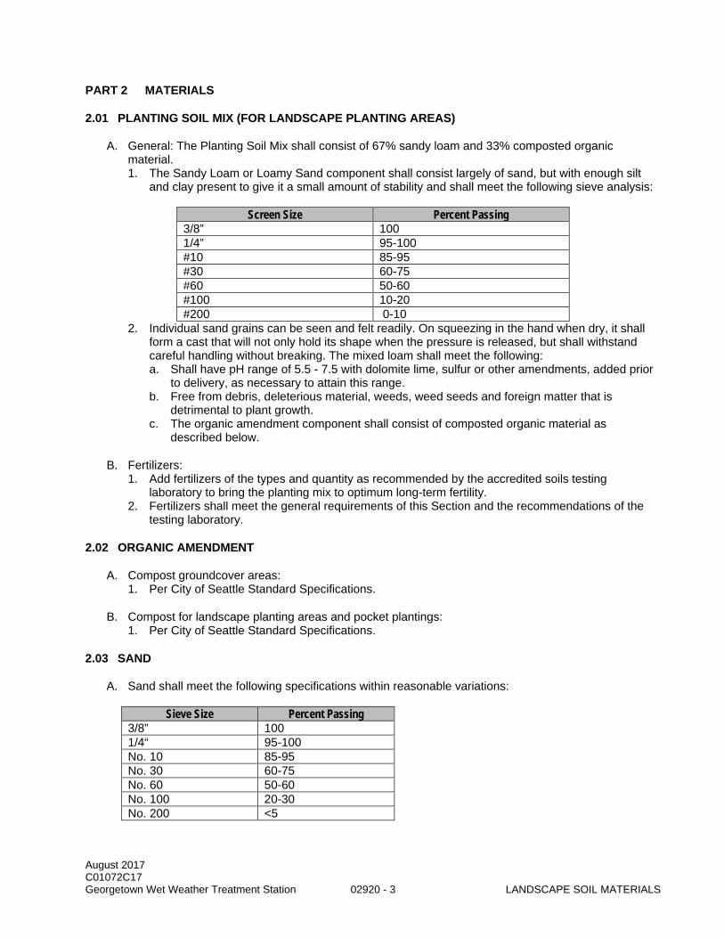
August 2017 C01072C17 Georgetown Wet Weather Treatment Station 02920 - 3 LANDSCAPE SOIL MATERIALS
PART 2 MATERIALS
2.01 PLANTING SOIL MIX (FOR LANDSCAPE PLANTING AREAS)
A. General: The Planting Soil Mix shall consist of 67% sandy loam and 33% composted organic material. 1. The Sandy Loam or Loamy Sand component shall consist largely of sand, but with enough silt
and clay present to give it a small amount of stability and shall meet the following sieve analysis:
Screen Size Percent Passing 3/8” 100 1/4” 95-100 #10 85-95 #30 60-75 #60 50-60 #100 10-20 #200 0-10
2. Individual sand grains can be seen and felt readily. On squeezing in the hand when dry, it shall form a cast that will not only hold its shape when the pressure is released, but shall withstand careful handling without breaking. The mixed loam shall meet the following: a. Shall have pH range of 5.5 - 7.5 with dolomite lime, sulfur or other amendments, added prior
to delivery, as necessary to attain this range. b. Free from debris, deleterious material, weeds, weed seeds and foreign matter that is
detrimental to plant growth. c. The organic amendment component shall consist of composted organic material as
described below.
B. Fertilizers: 1. Add fertilizers of the types and quantity as recommended by the accredited soils testing
laboratory to bring the planting mix to optimum long-term fertility. 2. Fertilizers shall meet the general requirements of this Section and the recommendations of the
testing laboratory.
2.02 ORGANIC AMENDMENT
A. Compost groundcover areas: 1. Per City of Seattle Standard Specifications.
B. Compost for landscape planting areas and pocket plantings: 1. Per City of Seattle Standard Specifications.
2.03 SAND
A. Sand shall meet the following specifications within reasonable variations:
Sieve Size Percent Passing 3/8” 100 1/4“ 95-100 No. 10 85-95 No. 30 60-75 No. 60 50-60 No. 100 20-30 No. 200 <5

August 2017 C01072C17 Georgetown Wet Weather Treatment Station 02920 - 4 LANDSCAPE SOIL MATERIALS
2.04 MINERAL AGGREGATE
A. General: 1. Mineral aggregate shall be free of wood, waste, coating, or and deleterious material. All mineral
aggregate passing the No. 200 sieve size shall be non-plastic. 2. Mineral Aggregate for planting soils shall be analyzed by an accredited lab using the sieve sizes
noted below, and shall meet the following gradation:
Sieve Size Percent Passing 1 inch 100 No. 4 60 - 100 No.10 40 - 100 No. 40 15 - 50 No. 200 2 - 5
3. Mineral Aggregate for planting soils shall meet the following gradation coefficients: Coefficient of Uniformity (Cu = D60/D10) equal to or greater than 6; and Coefficient of Curve (Cc = D302/D60D10) greater than or equal to 1 and less than or equal to 3.
2.05 FERTILIZERS
A. General: 1. Standard commercial grade of organic or inorganic fertilizer containing the amounts of total
nitrogen, available phosphoric acid, and water-soluble potash specified below. 2. Furnish in standard unopened containers with weight, name of plant nutrients, and
manufacturer’s statement of analysis clearly marked, in accordance with state and federal laws.
B. Fertilizer: 1. General:
a. 6-8-10 complete fertilizer, 50 percent of the nitrogen to be derived from natural organic sources or ureaform.
b. Available phosphoric acid shall be from superphosphate, bone, or tankage. c. 50 percent of the potash shall be derived from sulfate of potash-magnesium.
1) 6 percent nitrogen. 2) 10 percent phosphoric acid. 3) 8 percent potash.
2. Additives: a. F.T.E.: 2 percent. b. Multiracin: 0.5 percent.
3. Gradation: a. No. 4 sieve retains 0 percent. b. No. 20 sieve retains 65 percent. c. No. 80 sieve retains 100 percent.
2.06 LIME
A. General: 1. Agricultural grade mineral soil conditioner containing 35 percent minimum magnesium carbonate
and 49 percent minimum calcium carbonate, 100 percent passing No. 65 sieve.
B. Acceptable manufacturer: 1. Kaiser Dolomite 65 AG. 2. Approved Equal.

August 2017 C01072C17 Georgetown Wet Weather Treatment Station 02920 - 5 LANDSCAPE SOIL MATERIALS
2.07 PHOSPHORUS
A. Agricultural grade fertilizer providing the amount of available phosphoric acid specified below.
B. Bone Meal (1-23-0), superphosphate (0-20-0), or Approved Equal.
PART 3 EXECUTION
3.01 PREPARATION OF SUB-GRADE
A. Rip, disc, or scarify sub-grade soils to a minimum depth of 12 inches. Sub-grade elevations shall be as follows: 1. For Landscape Planting Areas - Sub-grade elevation 12 inches below finished grade or as noted
on plans.
3.02 SOIL PLACEMENT
A. For Landscape Planting Areas: 1. Place 12 inches of Planting Soil and thoroughly rototill soil into top 8 inches of prepared sub-
grade.
3.03 COMPACTION
A. Compact to 85 percent maximum density per ASTM D1557.
3.04 FINE GRADING
A. Perform fine grading to attain finish grades as shown on the Plans.
B. Rake out all rocks, roots, sticks and other debris larger than 2-inch diameter or sticks longer than 4 inches long. Leave surface even and readily able to accommodate lawn or planting installation.
END OF SECTION

August 2017 C01072C17 Georgetown Wet Weather Treatment Station 02920 - 6 LANDSCAPE SOIL MATERIALS
This page intentionally left blank.

DIVISION 03 CONCRETE

This page left intentionally blank.

August 2017 C001072C17 Georgetown Wet Weather Treatment Station 03200 - 1 CONCRETE REINFORCEMENT
SECTION 03200
CONCRETE REINFORCEMENT
PART 1 GENERAL
1.01 SUMMARY
A. This Section specifies reinforcing steel for use in reinforced concrete.
1.02 QUALITY CONTROL
A. Referenced Standards: This Section incorporates by reference the latest revision of the following documents. These references are a part of this Section as specified and modified. In case of conflict between the requirements of this Section and those of the listed documents, the requirements of this Section shall prevail.
Reference Title ACI 318 Building Code Requirements for Structural Concrete ASTM A615 Deformed and Plain Billet-Steel Bars for Concrete Reinforcement ASTM A706 Standard Specification for Deformed and Plain Low-Alloy Steel Bars for Concrete
Reinforcement ASTM A775 Standard Specification for Epoxy-Coated Steel Reinforcing ASTM D3963 Standard Specification for Fabrication and Jobsite Handling of Epoxy-Coated
Steel Reinforcing Bars ASTM E329 Standard Specification for Agencies Engaged in Construction Inspection,
Testing, or Special Inspection AWS D1.4 Structural Welding Code Reinforcing Steel CRSI-PRB Placing Reinforcing Bars CRSI-MSP Manual of Standard Practice ICC International Code Council
1.03 SUBMITTALS
A. Procedures: Section 01300.
B. Shop drawings and Product Data: 1. Technical data of reinforcing bars, dowel bars, tie bars, bar supports. 2. Reinforcing bar shop and placement drawings. 3. Bar lists and bending details. 4. Bar tags. 5. Welder qualification certificate in accordance with AWS. 6. Mechanical Threaded Connections: Current International Code Council (ICC) Evaluation Report
and Manufacturer’s Instructions.
PART 2 PRODUCTS
2.01 GENERAL (NOT USED)
2.02 MATERIALS
A. Bar Reinforcement: Deformed billet steel conforming to ASTM A615, Grade 60, including supplementary requirements except No. 2 bars.

August 2017 C001072C17 Georgetown Wet Weather Treatment Station 03200 - 2 CONCRETE REINFORCEMENT
B. Bar Reinforcement to be welded: Deformed billet steel conforming to ASTM A706, Grade 60. Welding reinforcing shall not be permitted unless indicated in the Drawing or permitted in writing by the Project Representative.
C. Epoxy-coated reinforcing bars shall conform to ASTM A775.
D. Tie Bars: Deformed billet steel bars conforming to the requirements of ASTM A615, Grade 60.
E. Mechanical Couplers, Form Savers or Splices: 1. Mechanical couplers, form savers or splices shall meet the requirements of a Type 2 mechanical
splice of ACI 318.
F. Bar Supports, Tie Wire and Trim Steel: 1. Bar supports coming into contact with forms shall be CRSI Class 1 plastic protected or Class 2
stainless steel protected and shall be located in accordance with CRSI MSP and placed in accordance with CRSI PRB. Concrete block supports shall be provided for footing and slabs on grade. Epoxy-coated or other dielectric-polymer-coated wire bar supports for epoxy-coated reinforcement, stainless steel, or plastic protected supports shall be provided for other work.
2. Locate in accordance with CRSI Manual of Standard Practice. 3. Reinforcing bars used as support bars for epoxy-coated reinforcing shall be epoxy-coated. 4. Show reinforcing steel required on the shop drawings. 5. Tie wire shall be black, soft-annealed 16 gage wire. 6. Unless otherwise indicated, use standard steel supports for other work. 7. Non-corrosive, non-rusting material where bar supports will be exposed to air, soil, water or
sewage.
PART 3 EXECUTION
3.01 INSTALLATION
A. Fabrication: 1. Reinforcing steel:
a. Do not bend or straighten in a manner that will damage the material. b. Do not use bars with kinks or with bends not indicated in the Drawings. c. Fabricate in accordance with CRSI MSP-1.
2. Heating or welding bars shall only be permitted where indicated in the Drawing or permitted in writing by the Project Representative. Unless otherwise indicated: a. Perform in accordance with AWS D1.4. b. Welders shall meet the requirements of AWS D1.4. c. Do not weld bars at the bend. d. Tack welding of cross bars is not acceptable.
B. Placement: 1. Place reinforcing steel in accordance with CRSI- PRB, the Drawings, and the applicable shop
drawing per the reinforcing steel supplier. 2. Include reinforcing steel as required by CRSI-MSP or CRSI-PRB when not specifically indicated
in the Drawings or explicitly referred to in the Specifications. 3. Unless otherwise indicated, provide concrete cover as indicated in the Drawings. 4. Position reinforcing steel accurately and secure against displacement at intersections with tie wire
and support by concrete or metal chairs, spacers or metal hangers. 5. Unless otherwise indicated, do not place reinforcing steel on fresh concrete or force the steel into
fresh concrete.

August 2017 C001072C17 Georgetown Wet Weather Treatment Station 03200 - 3 CONCRETE REINFORCEMENT
C. Splicing: 1. Lap splice reinforcing steel a Class B Lap Splice as provided by ACI 318 unless otherwise
indicated in the Drawings, or 24 inches if not shown. 2. In slabs, beams and walls subject to lateral pressure, do not splice reinforcing steel in areas of
maximum stress. 3. Unless otherwise indicated, stagger splices of adjacent bars as shown in the Drawings or as
required by ACI 318.
D. Mechanical Splices, including splices, couplers and form savers: 1. Mechanical Splices (ACI 318 Type 2) may be substituted for Lap. 2. Mechanical Splices (ACI 318 Type 2) shall be substituted for Lap Splices at any location where a
Class B Lap Splice cannot be placed due to congestion or conflicts of any kind. 3. Mechanical Splices shall be installed in accordance with the manufacturer’s recommendations.
E. Additional reinforcement around openings: 1. Additional reinforcement shall be placed around openings in concrete construction as provided in
the Drawings, at no additional cost. 2. If no reinforcing is indicated in a slab or wall, the Typical Opening Reinforcing Details indicated in
the Drawings shall be required. 3. In the event that the Typical Details do not apply, additional reinforcing equivalent to the cross
sectional area of the steel cut by the opening shall be added, equally distributed on all sides. The additional steel shall be extended beyond the limits of the opening a minimum of one development length (straight or hooked).
F. Cleaning: 1. Clean steel of mill rust scale, dried concrete, or other coatings that may reduce bond. 2. Reinforcement reduced in section is not acceptable. 3. Remove debris in the placement area prior to concrete placement. 4. When concrete placement is delayed, special cleaning of reinforcement may be required by the
Project Representative.
G. Repair: 1. Epoxy-coated reinforcing that is field-cut or damaged epoxy coatings shall be repaired in
accordance with ASTM D3963 and with material conforming to ASTM A775 in accordance with material manufacturer’s recommendation.
3.02 FIELD QUALITY CONTROL
A. Demonstrate conformance with the specified requirements for concrete reinforcement and welded rebar by an independent testing laboratory that complies with the requirements of ASTM E329.
B. The County may elect to also test concrete reinforcement Section 01410.
END OF SECTION

August 2017 C001072C17 Georgetown Wet Weather Treatment Station 03200 - 4 CONCRETE REINFORCEMENT
This page intentionally left blank.

August 2017 C01072C17 Georgetown Wet Weather Treatment Station 03301 - 1 CAST-IN-PLACE CONCRETE SMALL JOBS
SECTION 03301
CAST-IN-PLACE CONCRETE SMALL JOBS
PART 1 GENERAL
1.01 SUMMARY
A. This Section specifies cast-in-place reinforced concrete, including embedded material and formwork.
1.02 QUALITY ASSURANCE
A. Referenced Standards: This Section incorporates by reference the latest revision of the following document. These references are a part of this Section as specified and modified. In case of conflict between the requirements of this Section and those of the listed documents, the requirements of this Section shall prevail. Reference Title ACI 301 Specifications for Structural Concrete for Buildings ACI 318 Building Code Requirements for Reinforced Concrete ACI 211.1 Standard Practice for Selecting Proportions for Normal, Heavyweight, and Mass
Concrete ASTM A615 Specification for Deformed and Plain Billet-Steel Bars for Concrete
Reinforcement ASTM A775 Standard Specification for Epoxy-Coated Steel Reinforcing ASTM C33 Specification for Concrete Aggregates ASTM C94 Specification for Ready-Mixed Concrete ASTM C150 Specification for Portland Cement ASTM C618 Standard Specification for Coal Fly Ash and Raw or Calcined Natural Pozzolan
for Use in Concrete ASTM C989 Standard Specification for Slag Cement for Use in Concrete and Mortars ASTM E329 Specification for Agencies Engaged in Construction Inspection, Testing, or
Special Inspection CRSI-MSP Manual of Standard Practice
B. Concrete construction shall conform to the requirements of ACI 301.
1.03 SUBMITTALS
A. Procedures: Section 01300.
B. Concrete-Mix Designs.
C. Reinforcing Steel.
D. Concrete Placement Drawings.
E. Waterstops.
F. Surface Retarder.
G. Curing Compound.
H. Bonding and Repair Materials.

August 2017 C01072C17 Georgetown Wet Weather Treatment Station 03301 - 2 CAST-IN-PLACE CONCRETE SMALL JOBS
I. Surface Hardener.
1.04 TESTING
A. Perform and submit materials testing to demonstrate conformance with the specifications.
B. Perform Quality Control per Section 01410.
1.05 CONCRETE MIX DESIGNS
A. Compressive Strengths: unless otherwise specified, provide the following as minimum: 1. Concrete walls and slabs: 4500 psi. 2. Concrete paving: 4000 psi. 3. Concrete post foundations: 2000 psi. 4. Concrete fill: 2500psi using 1-inch aggregate, 4-inch maximum slump and 0.46 maximum
water-cement ratio.
PART 2 PRODUCTS
2.01 REINFORCEMENT
A. Comply with the following as minimums: 1. Reinforcing Bars - ASTM A615, grade 60, unless otherwise shown, using deformed bars for
Number 3 and larger. 2. Epoxy-coated Bars – ASTM A775. 3. Bending - ACI 318.
B. Fabricate reinforcement to the required shapes and dimensions, within fabrication tolerances stated in the CRSI.
C. Do not use reinforcement having any of the following defects: 1. Bar lengths, depths, or bends exceeding the specified fabricating tolerances. 2. Bends or kinks not indicated on the Drawings or required for this work. 3. Bars with cross-section reduced due to excessive rust or other causes. 4. Damaged epoxy coating on epoxy-coated reinforcing bars.
2.02 CONCRETE
A. Minimum Requirements: 1. Portland Cement: ASTM C150, Type I or II, low-alkali. 2. Aggregate, General:
a. ASTM C33 uniformly graded and clean. b. Do not use aggregate known to cause excessive shrinkage.
3. Aggregate, Coarse: crushed rock or washed gravel with size between 3/4-inch and 1-1/2 inches. 4. Aggregate, Fine: natural washed sand of hard and durable particles varying from fine to particles
passing a 3/8-inch screen, of which at least 12 percent shall pass a 50-mesh screen. 5. Water: clean and potable. 6. Supplementary Cementitious Materials (SCM):
a. Flyash: ASTM C618, Class F. Maximum 20% of cementitious content by weight. b. Slag cement: ASTM C989, Grade 110 or 120. Maximum 50% of cementitious content by
weight. c. Silica Fume: ACI 211.1. Maximum 10% of cementitious content by weight. d. Calcined Pozzolan: ASTM C618, Class N. Maximum 20% of cementitious content by
weight.

August 2017 C01072C17 Georgetown Wet Weather Treatment Station 03301 - 3 CAST-IN-PLACE CONCRETE SMALL JOBS
e. Slag plus Flyash/Other Pozzolan plus Silica Fume: Maximum 50% of cementitious content by weight.
f. Pozzolan plus Silica Fume: Maximum 30% of cementitious content by weight.
2.03 GROUT
A. For equipment use non-shrink, non-straining, premixed grout. Apply in accordance with the manufacturer's recommendations. 1. Acceptable Manufacturers and Products:
a. BASF Building Systems, Inc., Shakopee, MN; Master Flow 928. b. Five Star Products Inc., Fairfield, CT; Five Star 100. c. Euclid Chemical Co., Cleveland, OH; Hi Flow Grout. d. Dayton Superior Corp., Miamisburg, OH; Sure Grip High Performance Grout. e. L & M Construction Chemicals, Inc., Omaha, NE; Crystex. f. Approved Equal.
B. For Anchoring Dowels and Reinforcing Bars: Epoxy grout shall be medium viscosity epoxy conforming to ASTM C 881 Types I, II, III, Class B and C. Application shall be per the manufacturer's recommendations. 1. Acceptable Manufacturers and Products:
a. BASF Building Systems, Inc., Shakopee, MN; Masterflow 648 CP Plus. b. Five Star Products, Inc., Fairfield, CT; DP Epoxy Grout. c. Approved Equal.
2.04 BONDING AGENT
A. Epoxy Adhesive Bonding Agent: A two-component compound, 100 percent solids, 100 percent reactive compound suitable for use on dry or damp surfaces. Provide manufacturer's specific instructions for application.
B. Acceptable manufacturers and products: Concresive Liquid (LPL) by Master Builders, Inc., or Sikadur 32 Hi-Mod LPL by Sika Corporation, or Approved Equal.
2.05 OTHER MATERIALS
A. Provide other materials, not specifically described but required for a complete and proper installation as selected by the Contractor.
PART 3 EXECUTION
3.01 EXISTING CONDITIONS
A. Examine the areas and conditions under which work of this Section will be performed. Correct conditions detrimental to timely and proper completion of the Work. Do not proceed until unsatisfactory conditions are corrected.
3.02 REINFORCING
A. Per Section 03200.
3.03 EMBEDDED ITEMS
A. Do not embed piping in structural concrete unless indicated in the Drawings.

August 2017 C01072C17 Georgetown Wet Weather Treatment Station 03301 - 4 CAST-IN-PLACE CONCRETE SMALL JOBS
B. Set and secure bolts, inserts, and other required items in the precise locations needed so they are not displaced.
C. Prior to concrete placement, assure the actual locations of embedded items are noted on the as-built set of drawings.
3.04 FORMS
A. Design, erect, support, brace, and maintain formwork to safely support vertical and lateral loads, which will be applied until such loads can be supported safely by the concrete structure.
B. Construct forms to the exact sizes, shapes, lines, and dimensions shown, and as required to obtain accurate alignment, location, grades, and level and plumb work in the finished structure.
C. Chamfer all corners ¾ inches. Provide adequate triangular moldings in forms for all chamfering required.
3.05 MIXING CONCRETE
A. Transit mix the concrete in accordance with provisions of ASTM C94.
B. Do not use concrete that has stood for over 30 minutes after leaving the batch plant, or concrete that is not placed within 90 minutes after water is first introduced into the mix.
3.06 PLACING CONCRETE
A. Preparation: 1. Remove foreign matter accumulated in the forms. 2. Rigidly close openings left in the formwork. 3. Wet wood forms sufficiently to tighten up cracks; wet other material sufficiently to maintain
workability of the concrete. 4. Use only clean tools. 5. Unless tremie method for placing concrete is specified, remove water from space to be occupied
by concrete.
B. Conveying: 1. Perform concrete placing at such a rate that concrete, which is being integrated with fresh
concrete is still plastic. 2. Deposit concrete as nearly as practicable in its final location so as to avoid separation due to re-
handling and flowing. 3. Do not use concrete, which becomes non-plastic and unworkable, or does not meet required
quality control limits, or has been contaminated by foreign materials. 4. Remove concrete from the work site that does not meet specifications.
C. Placing Concrete In Forms: 1. Deposit concrete in horizontal layers not deeper than 24 inches, and avoid inclined construction
joints. 2. Remove temporary spreaders in forms when concrete has reached the elevation of the
spreaders.
D. Placing Concrete Slabs: 1. Deposit and consolidate concrete slabs in a continuous operation, within limits of construction
joints, until the placing of a panel or section is completed. 2. Bring slab surfaces to the correct level with a straightedge, and then strike off. 3. Use bullfloats or darbies to smooth the surface, leaving the surface free from bumps and hollows.

August 2017 C01072C17 Georgetown Wet Weather Treatment Station 03301 - 5 CAST-IN-PLACE CONCRETE SMALL JOBS
4. Do not sprinkle water on the plastic surface. 5. Do not disturb the slab surface prior to start of finishing operations.
3.07 CONSOLIDATION
A. Consolidate each layer of concrete while placing by use of internal concrete vibrators and supplemented by hand spading, rodding, or tamping.
B. Do not vibrate forms or reinforcement.
C. Do not use vibrators to transport concrete inside the forms.
3.08 JOINTS
A. Construction Joints: 1. Unless shown otherwise, do not use horizontal construction joints. 2. If construction joints are found to be required, submit for the Project Representative's approval of
joint design and location prior to start of concrete placement.
3.09 CONCRETE FINISHING
A. Unless otherwise indicated, provide the following finishes at the indicated locations. 1. Scratch finish: apply to monolithic slab surfaces that are to receive concrete floor topping or
mortar setting bed. 2. Float finish: apply to monolithic slab surfaces that are to receive trowel finish and other finishes
specified hereinafter. 3. Trowel finish: apply to monolithic slab surfaces that are to be exposed to view, unless otherwise
shown. 4. Non-slip broom finish: apply to walks, drives, ramps and similar pedestrian and vehicular areas.
3.10 BONDING TO OLD CONCRETE
A. Clean existing concrete surfaces by using wet sandblast or ultra-high pressure water jet to remove the surface film and contaminants. Coat the contact surfaces with bonding agent specified hereinbefore. Apply the bonding agent in conformance with the manufacturer's instruction. As concrete is placed, thoroughly vibrate against the contact overface. Concrete at the contact surface should be revibrated deeply as late as the running vibrator will penetrate the concrete of its own weight.
END OF SECTION

August 2017 C01072C17 Georgetown Wet Weather Treatment Station 03301 - 6 CAST-IN-PLACE CONCRETE SMALL JOBS
This page intentionally left blank.

August 2017 C01072C17 PRECAST CONCRETE ANCHOR Georgetown Wet Weather Treatment Station 03401 - 1 BLOCKS AND ACCESSORIES
SECTION 03401
PRECAST CONCRETE ANCHOR BLOCKS AND ACCESSORIES
PART 1 GENERAL
1.01 SUMMARY
A. This Section specifies requirements for precast concrete weights attached to the outfall pipe as indicated in the Drawings.
1.02 QUALITY ASSURANCE
A. Referenced Standards: This section incorporates by reference the latest revision of the following documents. These references are a part of this section as specified and modified. In case of conflict between the requirements of this section and those of the listed documents, the requirements of this section shall prevail.
Reference Title ACI 301 Specification for Structural Concrete ACI 318 Building Code Requirements for Structural Concrete ASTM A193 Alloy-Steel and Stainless Steel Bolting Material for High Temperature or High
Pressure Service ASTM A194 Carbon Steel, Alloy-Steel, and Stainless Steel Nuts for Bolts for High Temperature
or High Pressure Service ASTM A240 Chromium and Chromium-Nickel Stainless Steel Plate, Sheet, and Strip for
Pressure Vessels and General Applications ASTM A320 Alloy-Steel and Stainless Steel Bolting for Low Temperature Service ASTM A615 Deformed and Plain Billet-Steel Bars for Concrete Reinforcement, Grade 60 ASTM A767 Zinc-Coated (Galvanized) Steel Bars for Concrete Reinforcement ASTM B348 Titanium and Titanium Alloy Bars and Billets ASTM C150 Portland Cement ASTM D2000 Classification System for Rubber Products in Automotive Applications CRSI Manual of Standard Practice
B. Fabricator Qualifications: 1. Fabricator must have a minimum of 2 years of successful experience in fabrication of precast
concrete units similar to those required for this project and be approved by the Project Representative to be acceptable. Fabricator must have sufficient capacity to produce the required units without causing a delay in the work.
2. Produce precast concrete units at fabricating plant engaged primarily in manufacturing of concrete materials.
1.03 SUBMITTALS
A. Procedures: Section 01300.
B. Fabrication Shop Drawings, including reinforcing placement and location and material of lifting lugs.
C. Concrete Mix design.
D. Technical data for reinforcing bars.
E. Concrete test cylinder results.
August 2017 C01072C17 PRECAST CONCRETE ANCHOR Georgetown Wet Weather Treatment Station 03401 - 2 BLOCKS AND ACCESSORIES
F. Location of the fabrication area.
G. Fabricator Qualifications.
PART 2 PRODUCTS
2.01 GENERAL
A. Cement shall be ASTM C150, Type II or Type III containing not more than 5 percent tricalcium aluminate.
B. Concrete 28 day, compressive strength shall be 5,000 psi and conform to ACI 301 and ACI 318.
C. Concrete shall have a minimum cured weight of 150 lbs/cubic foot.
D. Reinforcing steel shall be ASTM A615, Grade 60, Class 2 galvanized after fabrication in accordance with ASTM A776.
E. All stainless steel components shall be ASTM A240 Type 316 nuts and threaded rods and shall conform to ASTM A193 and ASTM A194.
F. All titanium threaded rods and fasteners shall meet ASTM B348, Grade 2.
G. Lifting lugs shall be cast into the concrete weights so that the blocks may be lifted without using anchor bolts or HDPE pipe extensions.
H. Concrete test cylinders shall be taken and tested for each batch of concrete.
I. Neoprene shall conform to ASTM D2000 1BC, commercial grade and have Durometer hardness rating of 55 to 65.
PART 3 EXECUTION
3.01 GENERAL
A. All precast items shall be brought to the site complete.
B. All precast concrete items shall be allowed to fully cure for a minimum of 21 days before placement in water.
C. Install concrete pipe anchors without damage to the pipe at the locations indicated in the Drawings.
D. Do not install concrete anchors over butt fusion welded joints. If a fused joint occurs at a location where a concrete anchor is specified, consult with the Project Representative.
E. Care shall be taken in handling pipe after anchors have been installed so as not to place undue stress on the pipe.
F. All concrete anchors shall be carefully handled and protected against damage, impact shocks and free fall. Protect the pipe during anchor placement. All damaged materials shall be replaced at the Contractor’s expense.
August 2017 C01072C17 PRECAST CONCRETE ANCHOR Georgetown Wet Weather Treatment Station 03401 - 3 BLOCKS AND ACCESSORIES
3.02 FABRICATION
A. Reinforcing steel: 1. Do not bend or straighten in a manner that will damage the material. 2. Do not use bars with kinks or with bends not shown. 3. Do no heat or weld reinforcing bars. 4. Place reinforcing steel in accordance with CRSI, the Drawings, and the applicable shop drawing
per the reinforcing steel supplier. 5. Include all reinforcing steel as required by CRSI when not shown specifically on the Drawings or
explicitly referred to in the Specifications. 6. Position reinforcing steel accurately and secure against displacement at intersections with tie wire
and support by concrete or metal chairs, spacers, or metal hangers. 7. Bar ties shall be coated with epoxy, plastic, nylon, or other non-conductive material that will not
damage the coating. Bar supports and spacers shall be coated with or made of non-conductive material compatible with concrete.
8. Unless otherwise indicated, do not place reinforcing steel on fresh concrete or force the steel into fresh concrete.
9. Clean steel of mill rust scale, dried concrete, or other coatings that may reduce bond. 10. Reinforcement reduced in section is not acceptable. 11. Remove all debris in the placement area prior to concrete placement.
B. Anchor Block Construction: 1. Concrete shall be mixed only in the quantity required for immediate use. No retempering shall be
permitted. Concrete that has begun to harden shall be discarded and promptly disposed of. 2. All debris shall be removed from the interior of forms. 3. Coat surfaces of forms to be in contact with concrete with a bond-breaking compound before
reinforcing is placed. Provide a compound that will not bond with, stain or adversely affect concrete surfaces. Apply according to manufacturer’s written procedures.
4. Concrete shall be placed upon clean, damp surfaces with no free water or upon properly compacted even fills.
5. Place concrete in a continuous operation. No addition of concrete on or against set or hardened concrete will be accepted.
6. Compact and consolidate placed concrete without dislocation or damage to reinforcement and built in items.
7. Concrete shall be placed in forms by methods, which do not cause segregation. 8. Placed concrete shall be protected from weather to ensure proper curing. 9. Concrete surfaces that will be in contact with pipe either directly or through a neoprene pad shall
be smooth and without significant voids or protrusions.
3.03 DELIVERY, STORAGE AND HANDLING
A. Anchor blocks shall be fully cured and allowed to dry out before being moved.
B. Care shall be taken not to damage anchor blocks during storage or delivery.
C. Lift and support anchor blocks utilizing lifting lugs.
3.04 CONCRETE WEIGHT ANCHOR BLOCKS
A. A neoprene pad shall be permanently adhered to the block and strap at all locations that the pipe will bear upon. Neoprene shall be as indicated in the Drawings. Neoprene pad shall be of sufficient size to ensure the pipe will not be in direct contact with the concrete or strap.
B. The pipe bearing radius of the concrete block shall be beveled on each edge. The bevel shall be smooth without sharp corners, edges or protrusions that may contact the pipe either directly or under the neoprene pad.

August 2017 C01072C17 PRECAST CONCRETE ANCHOR Georgetown Wet Weather Treatment Station 03401 - 4 BLOCKS AND ACCESSORIES
C. The pipe bearing radius shall be fabricated of sufficient size to accommodate the outer diameter of the pipe and the attached neoprene pad so that the pipe rests evenly and the entire portion of the pipe radius within the pipe bearing area is in contact with the block via the neoprene pad.
D. Lifting lugs shall be utilized for lifting and positioning the anchor blocks. Anchor bolts shall not be utilized for lifting and positioning the blocks.
E. Bolts shall be tightened snug against the neoprene pads and pipe without distorting the pipes when tightened.
F. Maximum Bolt Torque: 1. Stainless Steel: 200 ft-lb. 2. Titanium: 150 ft-lb. 3. Calibration of the torque wrench shall be witnessed by the Project Representative.
3.05 WEIGHT TOLERANCES
A. Each concrete weight anchor shall be weighed in air after curing and drying out. The required concrete anchor minimum dry weights shall be as follows:
Anchor Types Minimum Cured Dry Weight (each)
C 8680
B. Any concrete anchor that is not within the weight tolerances shall be rejected, permanently and clearly marked as rejected and removed from the jobsite.
C. Supply all required equipment to complete the weighing activities. Provide equipment calibration information to the Project Representative. Provide a control weight to show equipment calibration.
D. Project Representative shall witness weighing activities. Number each concrete weight with a unique number. Provide a record of each concrete anchor weight by number and provide the Project Representative with a copy of said record.
END OF SECTION

DIVISION 05 METALS

This page left intentionally blank.

August 2017 C01072C17 Georgetown Wet Weather Treatment Station 05500 - 1 METAL FABRICATIONS
SECTION 05500
METAL FABRICATIONS
PART 1 GENERAL
1.01 SUMMARY
A. This Section specifies anchorage to concrete, fabricated metal items, and other miscellaneous metalwork, galvanized or coated.
1.02 QUALITY ASSURANCE
A. Referenced Standards: This Section incorporates by reference the latest revisions of the following documents. These references are a part of this Section as specified and modified. In case of conflict between the requirements of this Section and those of the listed documents, the requirements of this Section shall prevail. Reference Title AC193 Acceptance Criteria for Mechanical Anchors in Concrete Elements AC308 Acceptance Criteria for Post-Installed Adhesive Anchors in Concrete Elements ASTM A36 Structural Steel ASTM A53 Pipe, Steel, Black and Hot-Dipped, Zinc-Coated Welded and Seamless ASTM A108 Steel Bars, Carbon, Cold-Finished, Standard Quality ASTM A123 Zinc (Hot-Dip Galvanize) Coatings on Iron and Steel Products ASTM A153 Zinc Coating (Hot-Dip) on Iron and Steel Hardware ASTM A167 Stainless and Heat-Resisting Chromium-Nickel Steel Plate, Sheet and Strip ASTM A193 Alloy-Steel and Stainless Steel Bolting Materials for High-Temperature Service ASTM A194 Carbon and Alloy Steel Nuts for Bolts for High-Pressure and High-Temperature
Service, or Both ASTM A240 Heat-Resisting Chromium-Nickel Stainless Steel Plate, Sheet and Strip for
Pressure Vessels ASTM A276 Stainless Steel Bars and Shapes ASTM A307 Carbon Steel Bolts and Studs, 60,000 psi Tensile Strength ASTM A312 Seamless and Welded Austenitic Stainless steel Pipes ASTM A320 Alloy Steel Bolting Materials for Low Temperature Service ASTM A325 Structural Bolt, Steel, Heat Treated, 120/105 ksi Minimum Tensile Strength ASTM A496 Steel Wire, Deformed, for Concrete Reinforcement ASTM A500 Cold-Formed Welded and Seamless Carbon Steel Structural Tubing in Rounds
and Shapes ASTM A563 Carbon and Alloy Steel Nuts ASTM A615 Deformed and Plain Billet-Steel Bars for Concrete Reinforcement ASTM A780 Repair of Damaged and Uncoated Areas of Hot-Dip Galvanized Coatings ASTM A786 Rolled Steel Floor Plates ASTM A793 Rolled Floor Plate, Stainless Steel ASTM B209 Aluminum and Aluminum-Alloy Sheet and Plate ASTM B210 Aluminum and Aluminum-Alloy Drawn Seamless Tubes ASTM B211 Aluminum and Aluminum-Alloy Bar, Rod, and Wire ASTM B221 Aluminum and Aluminum-Alloy Extruded Bars, Rods, Wire, Profiles, and Tubes ASTM B241 Aluminum and Aluminum-Alloy Seamless Pipe and Seamless Extruded Tube ASTM B308 Aluminum-Alloy 6061-T6 Standard Structural Profiles ASTM B632 Aluminum-Alloy Rolled Tread Plate ASTM B695 Coatings of Zinc Mechanically Deposited on Iron and Steel ASTM F844 Washers, Steel, Plain (Flat), Unhardened for General Use AWS D1.1 Structural Welding Code of the American Welding Society

August 2017 C01072C17 Georgetown Wet Weather Treatment Station 05500 - 2 METAL FABRICATIONS
Reference Title AWS E70 Filler Material IBC International Building Code ICC International Code Council SSPS SP-5 White Metal Blast Cleaning WABO Washington Association of Building Officials
B. Shop and field welding shall conform to the requirements of AWS D1.1.
C. The use of salvaged, reprocessed or scrap materials will not be permitted.
D. All welding: by WABO certified welders.
E. The diameter and capacity of anchor bolts and concrete anchors shall be as recommended or required by the equipment or machinery manufacturer, including any recommended or required adjustment for seismic conditions. In case of conflicting or ambiguous recommendations or requirements, the most stringent shall apply.
F. Manufacturer's information showing the recommended installation equipment and procedures for the following: 1. Drilled-in concrete anchors. 2. Epoxy anchor shall include instructions for the safe handling of epoxy adhesives.
G. Design calculations and details showing the required diameter, length, embedment, edge distance, confinement, and other conditions, stamped and signed by a currently licensed state of Washington structural engineer.
H. Observation of Work: The Project Representative shall have access to any fabrication site or shop for the purpose of observing fabrication of items, structures, equipment, piping, electrical and other components which will be used in or incorporated in the work.
I. Notification of Start of Work: Notify the Project Representative in advance of the start of fabrication. For fabrication sites within 50 miles of the project site, provide 48 hours notice. For fabrication sites greater than 50 miles from the project site, provide 7 days notice.
J. Notification of Finish Work: Notify the Project Representative in advance of applying finish. For fabrication sites within 50 miles of the project site, provide 48 hours notice. For fabrication sites greater than 50 miles from the project site, provide 7 days notice.
1.03 SUBMITTALS
A. Procedures: Section 01300.
B. Manufacturer's product data showing conformance to the specifications.
C. Detailed shop drawings.
D. Welding/welding operator ASME Section IX and WABO certificates and qualifications for the work being performed.
E. Welding procedures.

August 2017 C01072C17 Georgetown Wet Weather Treatment Station 05500 - 3 METAL FABRICATIONS
PART 2 PRODUCTS
2.01 MATERIALS
A. Steel: Sheets, plates and shapes ASTM A36 Pipe ASTM A53, Grade B Square/rectangular tubing ASTM A500, Grade B Bolts ASTM A307, Grade A Nuts ASTM A563 Washers ASTM F844
B. Stainless Steel: Sheets and plates ASTM A240, Type 316 or 316L, or Type
2507 where indicated Pipe ASTM A312, Type 316 or 316L Threaded Rods ASTM A193 or A320, Type 316, or Type
2507 where indicated Bolts ASTM A193 or A320, Type 316, Class 1,
or Type 2507 where indicated Nuts ASTM A194, Type 316, or Type 2507
where indicated Washers ASTM A193 or A320, Type 316, or Type
2507 where indicated Drilled-in Concrete Anchors ASTM A193 or A320, Type 316, or Type
2507 where indicated Epoxy Concrete Anchors ASTM A193 or A320, Type 316, or Type
2507 where indicated Grouted Concrete Anchors ASTM A193 or A320, Type 316, or Type
2507 where indicated
C. Aluminum: Sheets and plates ASTM B209, Type 6061-T6 Bars, flats and similar items ASTM B211 or B221, Type 6061-T6 Shapes ASTM B221 or B308, Type 6061-T6 Round tubing and pipe ASTM B210 or B221, Type 6061-T6 Square and rectangular tubing ASTM B210, Type 6063-T52 Pipe ASTM B211 or B241, Type 6061-T6 Bolts ASTM A193 or A320, Type 316 Nuts ASTM A194, Type 316 Washers ASTM A193 or A320, Type 316
D. Checkered Plate: Steel ASTM A786 Stainless steel ASTM A793, Type 304 Aluminum ASTM B632, Type 6061-T6
2.02 ANCHORAGE

August 2017 C01072C17 Georgetown Wet Weather Treatment Station 05500 - 4 METAL FABRICATIONS
A. Supply components required for anchorage of fabrications. Fabricate anchors and related components of same material and finish as fabrication.
2.03 FASTENERS
A. As listed in this Section.
B. Finish: unless otherwise indicated, steel bolts, screws, nuts, washers and all other steel fasteners: mechanically zinc-coated in accordance with ASTM B695, Class 50.
C. Thread lubricant for stainless steel fasteners: where stainless steel bolts and threaded fasteners are used, apply anti-seizing lubricant to the threads prior to making up the connections. Lubricant: manufactured and labeled for use with stainless steel and shall contain substantial amounts of molybdenum disulfide, graphite, mica, talc or copper.
2.04 CONCRETE ANCHORS
A. Drilled-in concrete anchors: 1. Drilled-in concrete anchors: Drilled-in concrete anchors (post installed mechanical anchors) shall
have an ICC Evaluation Service Report (ESR) indicating compliance with the requirements of IBC 2012 for use in cracked and uncracked concrete for the anchor type and concrete strength conditions for which the anchor will be used. The ESR shall indicate IBC 2012 compliance for use under seismic loading conditions. The basis of the ESR shall be Acceptance Criteria for Mechanical Anchors in Concrete Elements (AC193):
2. Anchor: Type 316 stainless steel. 3. Acceptable Manufacturers:
a. Red Head Wedge anchors or Red Head Sleeve anchors by ITT Phillips. b. Kwik-Bolt stud type or HDI Drop-In anchors by Hilti, Inc. c. Wej-It by Wej-It Corporation. d. Parabolt PB anchors by Molly Division of Emhart Corp. e. Approved Equal.
B. Threaded-Rod Anchors: 1. Threaded-rod concrete anchors (post installed adhesive anchors) shall have an ICC Evaluation
Service Report (ESR) indicating compliance with the requirements of IBC 2012 for use in cracked and uncracked concrete for the anchor type and concrete strength conditions for which the anchor will be used . The ESR shall indicate IBC 2012 compliance for use under seismic loading conditions. The basis of the ESR shall be Acceptance Criteria for Post-Installed Adhesive Anchors in Concrete Elements (AC308).
2. Anchor Rod: Type 316, or Type 2507 as indicated on the drawings, stainless steel threaded rod free of grease, oil, or other deleterious material with a 45-degree chisel point.
3. Epoxy Adhesive: a. Meet ASTM C881, Type 1, Grade 3, Class A, B, or C. b. Two-component, 100 percent solids, non-sag, paste, insensitive to moisture, designed to be
used in adverse freeze/thaw environments, and gray in color. Cure Temperature, Pot Life, and Workability: Compatible for intended use and environmental conditions.
4. Mixed Epoxy Adhesive: Non-sag paste consistency with ability to remain in a 1-inch diameter overhead drilled hole without runout, holding the following properties: a. Slant Shear Strength, ASTM C881 and ASTM C882, No Failure in Bond Line, Dry/Moist
Conditions: 5,000 psi. b. Compressive Strength, ASTM D695: 14,000 psi minimum. c. Tensile Strength, ASTM D695: 4,500 psi. d. Heat Deflection Temperature, ASTM D648: 135 degrees F, minimum.

August 2017 C01072C17 Georgetown Wet Weather Treatment Station 05500 - 5 METAL FABRICATIONS
5. Epoxy Adhesive Packaging: a. Disposable, self-contained cartridge system capable of dispensing both epoxy components in
the proper mixing ratio and fit into a manually or pneumatically operated caulking gun. b. Dispense components through a mixing nozzle that thoroughly mixes components and places
epoxy at base of predrilled hole. c. Mixing Nozzles: Disposable, manufactured in several sizes to accommodate sizes of anchor
rods. d. Cartridge Markings: Include manufacturer's name, batch number, mix ratio by volume,
product expiration date, ANSI hazard classification, and appropriate ANSI handling precautions.
6. Storage of Epoxy adhesive: a. Store epoxy cartridges on pallets or shelving in a covered storage area. b. Control temperature above 60 degrees F and dispose of cartridges if shelf life has expired. If
stored at temperatures below 60 degrees F, test adhesive prior to use to determine if adhesive meets specified requirements.
7. Acceptable manufacturers: a. Hilti, Inc. b. Simpson Strong-Tie, Inc. c. Approved Equal.
C. Grouted concrete anchors shall be stainless steel threaded rod, anchored in a predrilled hole with nonshrink grout complying with the requirements of Section 03301. Submit specific use and design calculations for review and approval by the Project Representative.
2.05 WELDED ANCHOR STUDS
A. Headed anchor studs (HAS) or threaded anchor studs (TAS), as indicated in the drawings. 1. Carbon Steel: ASTM A108, Standard Quality Grades 1010 through 1020, inclusive either
semikilled or killed aluminum or silicon dioxidation, unless indicated otherwise.
2.06 FALL PROTECTION EQUIPMENT
A. Fall protection davit base: 1. Floor-mount cast-in-place sleeve davit base. 2. Install flush with concrete floor. 3. Provide closed end sleeve with drain hole into drop structure 4. Stainless steel. 5. Manufacturers:
a. DBI/SALA Model 8512828. No substitutions allowed.
B. Tie-off floor anchor: 1. Galvanized forged steel or stainless steel. 2. 3/4" diameter embedded stainless steel bolt. 3. Manufacturers:
a. Guardian Model 00372. b. DBI/SALA Model 2101004/2101004C. c. Approved equal.
2.07 STAINLESS STEEL: ASTM F593, AISI TYPE 316, CONDITION CW.PIPE SLEEVES
A. Schedule 40 pipe sleeves with continuously welded 3/16” thick seep ring with an outside diameter 3 inches greater than the sleeve outside diameter.

August 2017 C01072C17 Georgetown Wet Weather Treatment Station 05500 - 6 METAL FABRICATIONS
2.08 FINISH
A. Unless otherwise indicated: 1. Stainless steel: none. 2. Aluminum: coated as indicated in this Section.
PART 3 EXECUTION
3.01 EXAMINATION AND PREPARATION
A. Verify measurements at the Site.
B. Verify that field conditions are acceptable and are ready to receive work.
C. Make provisions for erection loads with temporary bracing. Keep work in alignment.
D. Supply items required to be cast into concrete or embedded in masonry with setting templates.
3.02 FABRICATION
A. Conform to AWS D1.1 minimum.
B. Grind exposed joints flush and smooth with adjacent finish surface. Make exposed joints butt-tight, flush, and hairline. Remove all burrs and weld splatter. Ease exposed edges to small uniform radius.
C. Punch holes 1/16-inch larger than the nominal size of the bolts, unless otherwise indicated. Whenever needed because of the thickness of the metal, subpunch and ream or drill holes.
D. Perform fabrication including cutting, drilling, punching, threading and tapping required for miscellaneous metal or adjacent work prior to hot-dip galvanizing.
3.03 FINISH
A. Welds and adjacent are to be prepared such that there are: 1. No undercutting or reverse ridges on the weld beads. 2. No weld spatter on or adjacent to the weld or any other area to be painted. 3. No sharp peaks or ridges along the weld bead.
B. All embedded pieces of electrode or wire and the adjacent weld: removed and replaced with new welds.
C. Obtain Project Representatives approval before applying finish.
3.04 INSTALLATION
A. Install items plumb, level and square, accurately fitted, and free from distortion or defects.
B. Allow for erection loads and provide temporary bracing to maintain true alignment until completion of erection and installation of permanent attachments.
C. Fieldwork shall not be permitted on galvanized items. Drilling of bolts or enlargement of holes to correct misalignment will not be allowed.
D. Protect encased or embedded dissimilar metals (both metals must be encased or embedded) from galvanic corrosion by means of pressure tapes, coatings or isolators.
August 2017 C01072C17 Georgetown Wet Weather Treatment Station 05500 - 7 METAL FABRICATIONS
E. Place metalwork to be embedded in concrete accurately and hold in correct position while the concrete is placed or, if indicated, form recesses or blockouts in the concrete. Thoroughly clean the surfaces of metalwork in contact with or embedded in concrete. If accepted, recesses may be neatly cored in the concrete after it has attained its design strength and the metalwork grouted in place.
F. Pipe Sleeves: 1. Provide a pipe sleeve wherever a pipe or similar item passes through concrete. 2. If not otherwise shown in the drawings provide a caulking sealant or a mechanical seal to form a
watertight seal of the annular space between pipes and pipe sleeves.
3.05 FIELD REPAIR OF COATINGS
A. Galvanized: 1. Maximum area to be repaired: no more than 1/2 of 1 percent of the surface area or 36 sq. in. per
ton of piece weight, whichever is less. Damage in excess of this requirement: repaired by stripping and recoating entire piece.
2. Clean damaged areas to SSPC-SP5. Repair with zinc-rich paint in accordance with the manufacturer's instructions and with ASTM A780, Annex A2. Minimum thickness requirements: in accordance with ASTM A123, Paragraph 6.2.3.
3. Use zinc-rich repair paint. 4. Acceptable manufacturers:
a. ZRC Galvilite. b. LPS Cold Galvanize c. Approved Equal.
B. Painted: after installation, clean and touch up damaged areas of with the same materials used for the shop coat.
3.06 ELECTROLYTIC CORROSION PROTECTION
A. Coat all surfaces of aluminum that are to be in contact with concrete, grout or dissimilar metals as indicated below. 1. Surface Preparation: Pressure wash followed by SSPS-SP-7 brush-off blast cleaning. 2. Coating: Two coats of Carboline Carboguard 890 VOC, 10 to 12 mils dry film thickness or
Approved Equal.
END OF SECTION

August 2017 C01072C17 Georgetown Wet Weather Treatment Station 05500 - 8 METAL FABRICATIONS
This page intentionally left blank.

August 2017 C01072C17 Georgetown Wet Weather Treatment Station 05520 - 1 METAL HANDRAILING
SECTION 05520
METAL HANDRAILING
PART 1 GENERAL
1.01 SUMMARY
A. This Section specifies prefabricated aluminum and steel handrailing.
1.02 QUALITY ASSURANCE
A. Referenced Standards: This Section incorporates by reference the latest revision of the following documents. These references are a part of this Section as specified and modified. In case of conflict between the requirements of this Section and those of the listed documents, the requirements of this Section shall prevail. Reference Title AA DAF-45 Designation System for Aluminum Finishes ASTM A320 Specification for Alloy/Steel Bolting Materials for Low-Temperature Service ASTM B241 Specification for Aluminum and Aluminum-Alloy Seamless Pipe and Seamless
Extruded Tube OSHA Occupational Safety and Health Administration, 29 CFR 1910, Code of Federal
Regulations SBC Seattle Building Code
1.03 SUBMITTALS
A. Procedures: Section 01300.
B. Certified test reports: before fabrication of handrailing, provide certificates which attest to their material complying with this Section.
C. Design calculations prepared by a professional engineer registered in the State of Washington.
D. Layout or installation shop drawings, including accessories and fasteners.
1.04 DESIGN REQUIREMENTS
A. Handrailing shall meet the requirements of the standards of the Occupational Safety and Health Administration, the Division of Industrial Safety and Health of the State of Washington, and the SBC.
B. Design calculations shall include anchorage to concrete.
1.05 DELIVERY, STORAGE AND HANDLING
A. Cushion wrap complete rails, modules and components to prevent scratching and denting during shipment, storage, and installation. Leave wrap intact, insofar as possible, until railing is completely installed.
1.06 FIELD MEASUREMENTS
A. Before fabrication verify that field measurements are as indicated in the Drawings, report deviations to the Project Representative.

August 2017 C01072C17 Georgetown Wet Weather Treatment Station 05520 - 2 METAL HANDRAILING
PART 2 PRODUCTS
2.01 GENERAL
A. Provide toeboards at guardrails of materials matching the guardrails.
B. System shall accommodate field cutting of posts to fit, prior to installation or attachment to base connections.
2.02 ALUMINUM RAILING SYSTEM
A. Acceptable Manufacturer: 1. Reynolds Metals Company. 2. Julius Blum and Company, Inc. 3. Thompson Fabricating Co. 4. Universal Products, Inc. 5. Approved Equal.
B. Materials: 1. Rails and posts: 1-1/2 inches nominal, ASTM B241, Alloy 6061-T6 or 6063-T6. 2. Fittings: cast aluminum elbows, T-shapes, wall brackets, escutcheons. 3. Splice connectors: aluminum concealed spigot. 4. Bolts, nuts, washers: ASTM A320, Type 304 stainless steel. 5. Handrail Gate: ASTM B241, Alloy 6063-T6, 6105-T5 or 6061-T6. 6. Hardware: Gate hinges with spring, gate latch, gate stop, and lock.
C. Finishes: clear anodized in accordance with the Aluminum Association AA-M32-C22-A41. Anodize exposed prefabricated components, except stainless steel fasteners, after fabrication.
2.03 FABRICATION
A. Fit and assemble components in largest practical sizes, for delivery to the Site.
B. Pipe cuts shall be clean, straight, square, and accurate for minimum joint gap. Perform work in conformance with the handrail manufacturer's instructions. Work shall be free from blemishes, defects, and misfits that can affect durability, strength, or appearance.
C. Unless otherwise indicated, supply components required for anchorage of fabrications.
D. Grind exposed joints flush and smooth with adjacent finish surface. Make exposed joints butt-tight, flush and hairline. Ease exposed edges to small, uniform radius.
PART 3 EXECUTION
3.01 EXAMINATION
A. Verify measurements at the Site.
B. Verify that field conditions are acceptable and are ready to receive work.
3.02 PREPARATION
A. Supply items required to be cast into concrete with setting templates.
August 2017 C01072C17 Georgetown Wet Weather Treatment Station 05520 - 3 METAL HANDRAILING
3.03 INSTALLATION
A. Install in accordance with manufacturer's instructions.
B. Protect dissimilar metals from galvanic corrosion by means of pressure tapes, coatings, or isolators.
C. Protect aluminum in contact with concrete or grout with a heavy coat of bituminous paint.
D. Install components plumb and level, accurately fitted, free from distortion or defects.
E. Unless otherwise indicated, no field welding of handrails shall be permitted. Where field welding is specified, grind, weld smooth to match adjacent pipe and coat.
3.04 TOLERANCES
A. Maximum variance from plumb: 1/4-inch per story.
B. Maximum offset from true alignment: 1/4-inch.
END OF SECTION

August 2017 C01072C17 Georgetown Wet Weather Treatment Station 05520 - 4 METAL HANDRAILING
This page intentionally left blank.

DIVISION 08 DOORS AND WINDOWS

This page left intentionally blank.

August 2017 C01072C17 Georgetown Wet Weather Treatment Station 08310 - 1 ACCESS HATCHES
SECTION 08310
ACCESS HATCHES
PART 1 GENERAL
1.01 SUMMARY
A. Work includes furnishing and installing factory fabricated access hatches.
1.02 QUALITY ASSURANCE
A. Referenced Standards: This Section incorporates by reference the latest revision of the following document. These references are a part of this Section as specified and modified. In case of conflict between the requirements of this Section and those of the listed documents, the requirements of this Section shall prevail. Reference Title ASTM A36 Standard Specification for Structural Steel ASTM A123 Standard Specification for Zinc (Hot-Dip Galvanized) Coatings on
Iron and Steel Products Occupational Safety & Health Administration (OSHA): 29 CFR 1910.23
Fall Protection in General Industry
1.03 SUBMITTALS
A. Procedures: Section 01300.
B. Product Data: Provide manufacturer's product data for all materials in this specification.
C. Shop Drawings: Show profiles, accessories, location, and dimensions.
D. Samples: Manufacturer to provide upon request; sized to represent material adequately.
E. Contract Closeout: Access door manufacturer shall provide the manufacturer's Warranty prior to the contract closeout.
1.04 PRODUCT HANDLING
A. All materials shall be delivered in manufacturer's original packaging.
B. Store materials in a dry, protected, well-vented area. Thoroughly inspect product upon receipt and report damaged material immediately to delivering carrier and note such damage on the carrier's freight bill of lading.
1.05 JOB CONDITIONS
A. Verify that other trades with related work are complete before installing vault access door(s).
B. Mounting surfaces shall be straight and secure; substrates shall be of proper width.
C. Comply with the construction documents, shop drawings, and manufacturer's installation instructions.

August 2017 C01072C17 Georgetown Wet Weather Treatment Station 08310 - 2 ACCESS HATCHES
PART 2 PRODUCTS
2.01 SCHEDULE
Location Hatch Dimensions [1] Type Loading Drop Structure 30”X30” Single Door Pedestrian Drop Structure 36”x84” Double Door (36”x42”
per door) Pedestrian
[1] Hatch dimensions indicated are clear inside dimensions without obstructions.
2.02 FLOOR HATCHES
A. Acceptable Manufacturers: 1. Bilco Co., New Haven, CT; K Series. 2. Nystrom Building Products Co., Minneapolis, MN; FH Series. 3. U.S.F. Fabrication, Hialeah, FL; A Series. 4. Flyght Corp., Trumbull, CT; FLE Series. 5. Thompson Fabricating Co., Birmingham, AL; TI Series. 6. Halliday Products, Orlando, FL; SS Series. 7. Approved Equal.
B. Load Capacity: 150 psf in foot traffic areas with maximum deflection of 1/150th of span.
C. Component Fabrication: 1. Access Door Leaf(s): 1/4-inch thick aluminum diamond pattern plate. Provide stainless steel
safety chain and attachments for end of double-leaf door assembly when open. 2. Angle Frame: 1/4-inch thick extruded aluminum angle frame with concrete anchors and integral
neoprene gasket strip.
D. Door Hardware: 1. Hinges: Heavy-duty brass or stainless steel with stainless steel pins, through-bolted to cover plate
with tamper-proof stainless steel bolts flush with top of cover and to outside leg of channel frame with stainless steel bolts and locknuts.
2. Lifting Mechanism: Stainless steel compression lift springs enclosed in telescoping vertical housing or stainless steel torsion lift springs.
3. Hold-Open Arm: a. Locks automatically in open position. b. Disengages with slight pull on vinyl grip with one hand. c. Door can be easily closed with one hand by pulling forward and down on vinyl grip.
4. Snap Lock: a. Stainless steel snap lock mounted on bottom of door leaf with removable topside key wrench
and inside fixed lever handle. b. Threaded plug for flush outside surface with key wrench removed.
5. Lock: a. Recessed padlock hasp.
E. Aluminum shall be mill finished with protective coating applied to surfaces to be in contact with concrete.

August 2017 C01072C17 Georgetown Wet Weather Treatment Station 08310 - 3 ACCESS HATCHES
PART 3 EXECUTION
3.01 EXISTING CONDITIONS
A. Examine the areas and conditions under which work of this Section will be performed. Correct conditions detrimental to timely and proper completion of the Work. Do not proceed until unsatisfactory conditions are corrected. Verify that the substrate is dry, clean, and free of foreign matter. Report and correct defects prior to any installation.
3.02 INSTALLATION
A. Submit product design drawings for review and approval to the Project Representative before fabrication.
B. Check as-built conditions and verify the manufacturer's vault access door details for accuracy to fit the application prior to fabrication. Comply with the vault access door manufacturer's installation instructions.
C. Furnish mechanical fasteners consistent with the vault access door manufacturer's instructions.
3.03 ADJUSTING AND CLEANING
A. Adjust doors and hardware after installation for proper operation.
B. Remove and replace doors and frames that are warped, bowed, or otherwise damaged.
END OF SECTION

August 2017 C01072C17 Georgetown Wet Weather Treatment Station 08310 - 4 ACCESS HATCHES
This page intentionally left blank.

DIVISION 11 EQUIPMENT

This page left intentionally blank.

August 2017 C01072C17 Georgetown Wet Weather Treatment Station 11009 - 1 EQUIPMENT LIST
SECTION 11009
EQUIPMENT LIST
PART 1 GENERAL
1.01 SUMMARY
A. This Section provides a list of the new equipment to be incorporated in the work. Each ID number is prefixed with a standard abbreviation to indicate the function of the particular device. Prefixes for mechanical and electrical equipment shall be from the King County standard abbreviations Drawing or Specifications.
1.02 QUALITY ASSURANCE (NOT USED)
1.03 SUBMITTALS (NOT USED)
1.04 COMPLETENESS (NOT USED)
1.05 NUMBERING SYSTEM
A. The following example describes how the equipment identification system is developed. 1. FT 854101A Where FT = Equipment function; 854 = Facility Number; 101 = Equipment or Loop
Number; A, B, etc. = parallel or sequential elements.
B. Each ID number is prefixed with a standard abbreviation to indicate the function of the particular device. Prefixes for mechanical and electrical equipment shall be from the County’s standard abbreviations Drawing included in this Contract.
C. Equipment Status: The following are used to represent equipment status: 1. E = Existing. 2. M = Modify. 3. F = Future. 4. D = Demolish or remove, do not replace. 5. N = New. 6. R = Remove, Replace with new.
PART 2 PRODUCTS
2.01 NAMEPLATES (NOT USED)
2.02 EQUIPMENT SCHEDULE
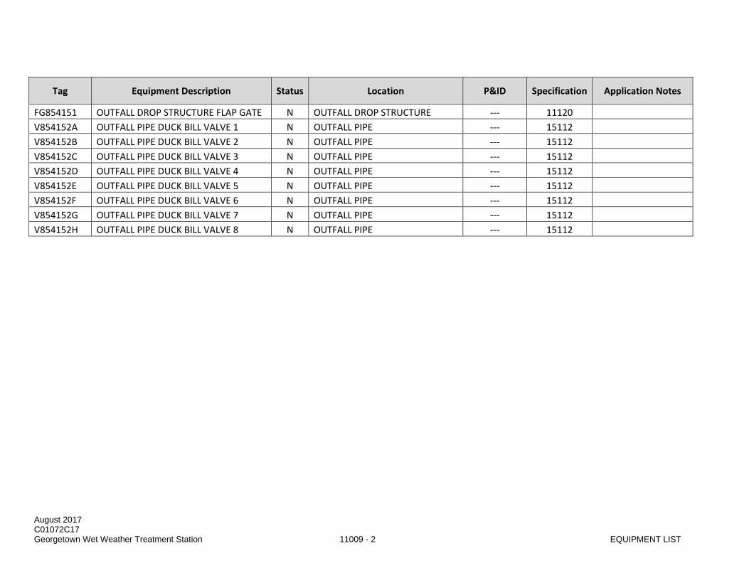
August 2017 C01072C17 Georgetown Wet Weather Treatment Station 11009 - 2 EQUIPMENT LIST
Tag Equipment Description Status Location P&ID Specification Application Notes
FG854151 OUTFALL DROP STRUCTURE FLAP GATE N OUTFALL DROP STRUCTURE --- 11120 V854152A OUTFALL PIPE DUCK BILL VALVE 1 N OUTFALL PIPE --- 15112 V854152B OUTFALL PIPE DUCK BILL VALVE 2 N OUTFALL PIPE --- 15112 V854152C OUTFALL PIPE DUCK BILL VALVE 3 N OUTFALL PIPE --- 15112 V854152D OUTFALL PIPE DUCK BILL VALVE 4 N OUTFALL PIPE --- 15112 V854152E OUTFALL PIPE DUCK BILL VALVE 5 N OUTFALL PIPE --- 15112 V854152F OUTFALL PIPE DUCK BILL VALVE 6 N OUTFALL PIPE --- 15112 V854152G OUTFALL PIPE DUCK BILL VALVE 7 N OUTFALL PIPE --- 15112 V854152H OUTFALL PIPE DUCK BILL VALVE 8 N OUTFALL PIPE --- 15112

August 2017 C01072C17 Georgetown Wet Weather Treatment Station 11009 - 3 EQUIPMENT LIST
PART 3 EXECUTION (NOT USED)
END OF SECTION

August 2017 C01072C17 Georgetown Wet Weather Treatment Station 11009 - 4 EQUIPMENT LIST
This page intentionally left blank.

August 2017 1001072C17 Georgetown Wet Weather Treatment Station 11120 - 1 FLAP GATES
SECTION 11120
FLAP GATES
PART 1 GENERAL
1.01 SUMMARY
A. This Section specifies double pivot flap gate, with all materials, works, and appurtenances necessary to make a complete and operable installation.
1.02 QUALITY ASSURANCE
A. Referenced Standards: This Section incorporates by reference the latest revision of the following documents. These references are a part of this Section as specified and modified. In case of conflict between the requirements of this Section and those of the listed documents, the requirements of this Section shall prevail. Reference Title ASTM A126 Specification for Gray Iron Castings for Valves, Flanges, and Pipe
Fittings ASTM A276 Specification for Stainless Steel Bars and Shapes AWWA C501 Standard for Sluice Gates NFPA 70 National Electrical Code IBC International Building Code
1.03 SUBMITTALS
A. Procedures: Section 01300.
B. Catalog data giving complete description of the flap gates.
C. Data, shop drawings, and descriptive material showing materials of fabrication, sizes and capacities, field verified dimensions, and installation requirements.
D. Operation and maintenance data per Section 01730.
1.04 SERVICE CONDITIONS
A. The 60-inch diameter flap gate shall be installed in the drop structure on a concrete wall that that serves as a physical separation between the outfall and the 60-inch effluent pipeline. The flap gate is positioned to be above the low tide elevation and below the high tide elevation. The flap gate will be subjected to tidal fluctuations and submerged by salt water during high tide.
B. The new gate can be subject to head differential as indicated in Table 1 below: Table 1 – Receiving Water Surface and Other Key Elevations
Condition Elevation Highest Observed Tide (HOT) 109.0 Mean Higher High Water (MHHW) 105.0 Mean Lower Low Water (MLLW) 93.6 Lowest Observed Tide (LOT) 89.0

August 2017 1001072C17 Georgetown Wet Weather Treatment Station 11120 - 2 FLAP GATES
Condition Elevation Flap Gate Invert 99.5
All elevations are based on METRO datum.
C. The flap gate will only need to unseat when the Georgetown Wet Weather Treatment Station (GWWTS) is in operation and conveying treated effluent to the outfall. The GWWTS will operate at a minimum capacity of 5 MGD and peak capacity of 70 MGD.
PART 2 PRODUCTS
2.01 GENERAL
A. All flap gates shall be fully factory assembled with frame, flap, hinges, seals, etc.
B. Provide thimble for mounting the gate to the concrete headwall and water stop to limit leakage at this joint.
C. J Bulb seals attached to the slide/mounted to the frame, or any seal that needs replacement in less than 10 years shall not be acceptable. No part of the seal shall protrude into the clear opening.
D. The flap gate manufacturer shall be fully experienced, reputable and qualified in the manufacturing of the equipment furnished and who has been building said equipment for a minimum of ten (10) years.
2.02 ACCEPTABLE MANUFACTURERS
A. The listed manufacturer is believed to have the capability of producing equipment and/or materials meeting the requirements. 1. Plasti-Fab, Inc., Tualatin, Oregon. 2. No Or Equal.
2.03 PERFORMANCE AND DESIGN REQUIREMENTS
A. Service Conditions: flap gates shall be suitable for service with treated wastewater and salt water.
B. Mounting: The flap gate shall be mounted to a concrete wall. Bolts shall be proof-loaded prior to installation.
C. The flap gate shall be designed to automatically open whenever the unseating head exceeds the seating head by 0.30 feet or less, and to automatically close whenever the seating head exceeds the unseating head. The flap gate shall close under its own weight when water upstream and downstream water levels are below the flap gate invert.
D. Design Requirements: No. of Units Diameter (in.) Type Maximum Design Seating
Head Seating, (ft) Centerline
Elevation (ft) 1 60 Rigid Flap 17.3 102
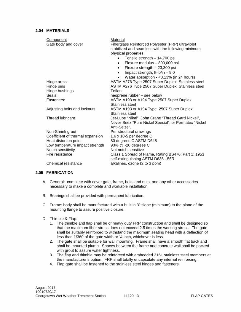
August 2017 1001072C17 Georgetown Wet Weather Treatment Station 11120 - 3 FLAP GATES
2.04 MATERIALS Component Material Gate body and cover Fiberglass Reinforced Polyester (FRP) ultraviolet
stabilized and seamless with the following minimum physical properties:
• Tensile strength – 14,700 psi • Flexure modulus – 800,000 psi • Flexure strength – 23,300 psi • Impact strength, ft-lb/in – 9.0 • Water absorption - <0.13% (in 24 hours)
Hinge arms: ASTM A276 Type 2507 Super Duplex Stainless steel Hinge pins ASTM A276 Type 2507 Super Duplex Stainless steel Hinge bushings Teflon Seals: neoprene rubber – see below Fasteners: ASTM A193 or A194 Type 2507 Super Duplex
Stainless steel Adjusting bolts and locknuts ASTM A193 or A194 Type 2507 Super Duplex
Stainless steel Thread lubricant Jet-Lube “Nikal”, John Crane “Thread Gard Nickel”,
Never-Seez “Pure Nickel Special”, or Permatex “Nickel Anti-Seize”.
Non-Shrink grout Per structural drawings Coefficient of thermal expansion 1.6 x 10⁻⁵ per degree C Heat distortion point 80 degrees C ASTM D648 Low temperature impact strength 93% @ -20 degrees C Notch sensitivity Not notch sensitive Fire resistance Class 1 Spread of Flame, Rating BS476: Part 1: 1953
self-extinguishing ASTM D635 - 56R Chemical resistance alkalines, ozone (2 to 3 ppm)
2.05 FABRICATION
A. General: complete with cover gate, frame, bolts and nuts, and any other accessories necessary to make a complete and workable installation.
B. Bearings shall be provided with permanent lubrication.
C. Frame: body shall be manufactured with a built in 3º slope (minimum) to the plane of the mounting flange to assure positive closure.
D. Thimble & Flap: 1. The thimble and flap shall be of heavy duty FRP construction and shall be designed so
that the maximum fiber stress does not exceed 2.5 times the working stress. The gate shall be suitably reinforced to withstand the maximum seating head with a deflection of less than 1/360 of the gate width or ¼ inch, whichever is less.
2. The gate shall be suitable for wall mounting. Frame shall have a smooth flat back and shall be mounted plumb. Spaces between the frame and concrete wall shall be packed with grout to assure water tightness.
3. The flap and thimble may be reinforced with embedded 316L stainless steel members at the manufacturer’s option. FRP shall totally encapsulate any internal reinforcing.
4. Flap gate shall be fastened to the stainless steel hinges and fasteners.

August 2017 1001072C17 Georgetown Wet Weather Treatment Station 11120 - 4 FLAP GATES
5. Manufacturer shall submit drawings and comprehensive design criteria to substantiate that the required deflection figure has been achieved. Comprehensive safety factor calculations shall include bending moments, buckling stress, and bonding stress with thermal expansion factors referenced in NASA CR-1457, "Manual for Plates and Shells". Safety factors shall be calculated for the flap under maximum head.
E. Seals: the flap gate shall be fitted with a fixed seating face that surrounds the clear opening. elastomeric seals shall have a hardness of 60/70 on Durometer A scale and conforming to ASTM Specification D2000 and have a maximum compression set of 25%, and low temperature brittleness to meet suffix F-17 (-40º F.) The flexible seal and hinge shall be mounted to maintain a watertight seal.
F. Anchorage: frame mounting shall be Type 316L stainless steel in accordance with the structural details.
PART 3 EXECUTION
3.01 INSTALLATION
A. The flap gate shall be installed at location shown in the Drawings and in accordance with the manufacturer's written instructions.
B. The flap gate shall be carefully installed for proper operation without binding. Care shall be taken to avoid warping the gate body to ensure uniform contact of seat faces when the cover is in the closed position. All the bolts shall be properly tightened, and all pivot pins shall be lubricated. Thread lubricant shall be liberally applied to the male threads of stainless steel anchor bolts and fasteners during the assembly and tightening to prevent galling.
C. Gates mounted directly on the vertical face of concrete walls shall be adjusted and grouted in place with non-shrink grout in accordance with the manufacturer’s recommendations.
3.02 FIELD TESTING
A. Under seating conditions the flap gates shall be watertight. Shop operating tests shall be performed as per AWWA C501, Section 23 and field operating and leakage tests shall be conducted as specified in AWWA C501, Section 28.
END OF SECTION

DIVISION 13 SPECIAL CONSTRUCTION

This page left intentionally blank.

August 2017 C010072C17 Georgetown Wet Weather Treatment Station 13110 - 1 CATHODIC PROTECTION SYSTEM
SECTION 13110
CATHODIC PROTECTION SYSTEM
PART 1 GENERAL
1.01 SUMMARY
A. This Section specifies a galvanic anode cathodic protection system for buried metal pipe. The system consists of magnesium anodes and all associated wiring and hardware as required for a complete and operable system.
B. The Drawings are diagrammatic and do not necessarily show all fittings, wiring or wiring devices required by code. Include in its bid these and related items and the work associated with their installation.
1.02 QUALITY ASSURANCE
A. Referenced Standards: This Section incorporates by reference the latest revision of the following documents. These references are a part of this Section as specified and modified. In case of conflict between the requirements of this Section and those of the listed documents, the requirements of this Section shall prevail. Reference Title ASTM B843 Magnesium Alloy Anodes for Cathodic Protection ASTM G97 Test Method for Laboratory Evaluation of Magnesium Sacrificial Anode Test
Specimens for Underground Applications NEMA WC 70 Nonshielded Power Cables Rated 2000 volts or less for Distribution of Electrical
Energy UL 44 Rubber Insulated Wires and Cables UL 467 Grounding and Bonding Equipment UL 510 Insulating Tape
B. Qualifications: 1. Performed work of this Section with a firm regularly engaged in the design, repair, and
maintenance of cathodic protection systems. Have a traceable, verifiable record of continuous, relevant work and performance for a minimum of three years.
2. All work shall be accomplished by qualified and experienced personnel working under continuous competent supervision.
1.03 SUBMITTALS
A. Procedures: Section 01300.
B. Manufacturer's product data showing conformance to the specifications for: 1. Galvanic anodes. 2. Wires. 3. Thermite weld materials. 4. Coating.

August 2017 C010072C17 Georgetown Wet Weather Treatment Station 13110 - 2 CATHODIC PROTECTION SYSTEM
PART 2 PRODUCTS
2.01 GENERAL
A. Materials shall be a standard product of a manufacturer regularly engaged in their production.
B. All components of the following materials shall be products of the same manufacturer to ensure compatibility and continuity.
C. No splices shall be permitted in wires other than at locations indicated in the Drawings.
2.02 MATERIALS
A. Prepackaged Anodes.
B. Wire.
C. Flush Mounted Test Station.
D. Shunts.
E. Reference Electrodes.
F. Thermite Welds.
G. Thermite Weld Coating.
2.03 PREPACKAGED ANODES
A. Prepackaged Anodes: 1. Nominal weight: 60 lbs. 2. Cross section: 4.375 inches by 4 inches, nominal. 3. Minimum length: 60 inches. 4. Steel wire core. 5. 50 percent efficient based on their dielectric consumption rate. 6. Classified as high potential magnesium, Grade MIC, anode alloy per ASTM B843. 7. Alloy: Open circuit potential of 1.70 -1.75 volts with respect to a saturated calomel electrode
based on the test procedure established in ASTM G97. 8. Chemical composition as follows:
a. Aluminum: 0.010 percent maximum. b. Manganese: 0. 5 to 1.3 percent. c. Zinc: 0.004 percent maximum. d. Silicon: 0.05 percent maximum. e. Copper: 0.02 percent maximum. f. Nickel: 0.001 percent maximum. g. Iron: 0.03 percent maximum. h. Other Impurities, each: 0.05 percent maximum. i. Other Impurities, total: 0.30 percent maximum. j. Magnesium: Balance Dow Magnesium Galvomag or Approved Equal.
9. Lead wire: Each anode shall have a black, Type HMWPE, , No. 4 AWG, stranded copper wire connected to one end of the steel wire core by means of silver soldering. The connection shall be insulated by filling the anode's recess area with an electrical potting compound. Anode wire length shall sufficient to extend from the anode to the test station or pipe connection splice free, plus 10 feet.

August 2017 C010072C17 Georgetown Wet Weather Treatment Station 13110 - 3 CATHODIC PROTECTION SYSTEM
10. Bag and Backfill: a. Packaged in a permeable cloth bag containing a backfill mixture composed of:
1) Hydrated Gypsum: 75 percent. 2) Bentonite Clay: 20 percent. 3) Sodium Sulfate: 5 percent.
b. The backfill mixture shall be firmly packaged around the magnesium anode within the cloth bag by means of adequate vibration, with at least two full inches of backfill mixture covering the entire surface of the anode.
c. Each anode shall have a packaged weight of not less than 125 lbs.
2.04 WIRES
A. Test Wires: No. 4 AWG stranded copper with HMWPE insulation.
B. Joint Bond Wires: 1. Type HMWPE, single conductor, stranded copper. Supply joint bonds complete with formed
copper sleeves on each end of the wire. 2. Push—On, Mechanical, or Flanged Joints: No. 2 AWG wires 18-inches long.
2.05 FLUSH MOUNTED TEST STATION
A. Utility Box: 1. H20 rated ductile iron box with galvanized steel lid, Olympic Foundry Type SM29, or Approved
Equal. 2. Include permanent marking on lid with words “CP TEST”.
B. Test Boards: 1/4-inch thick phenolic panel, NEMA Grade LE for electrical use under wet conditions.
C. Concrete: As specified in Section 03301, Cast-in-Place Concrete Small Jobs.
D. Anode Metering Shunts: 0.1 ohm, 2 ampere capacity, with 1 percent accuracy.
2.06 WIRE CONNECTORS
Wire-to-Flange Connectors: 1. Type 316L stainless steel plates with holes to accommodate flange bolt diameter. Dimensions as
shown on the drawings.
B. Wire-to-Terminal Board Connectors: 1. Non-insulated, ring type crimp connector properly sized for the appropriate wire and stud where
indicated. 2. UL 486. Thomas & Betts Co.
2.07 THERMITE WELD MATERIALS
A. Thermite welds: Thermite weld materials consist of wire sleeves, welders, and weld cartridges according to weld manufacturer’s recommendations for each wire size and pipe or fitting size and material. Welding materials and equipment shall be product of a single manufacturer. Interchanging materials of different manufacturer’s not acceptable.
B. Molds: Graphite. Ceramic “One-Shot” molds not acceptable.
C. Adapter Sleeves: 1. For No. 4 AWG and No. 2 AWG wires. 2. Extend wire conductor ¼-inch beyond end of sleeve.

August 2017 C010072C17 Georgetown Wet Weather Treatment Station 13110 - 4 CATHODIC PROTECTION SYSTEM
D. Use cast iron thermite weld cartridges for cast and ductile iron pipe and fittings.
E. Maximum Cartridge Size: 25 grams for steel and 32 grams for cast and ductile iron pipe materials.
F. Welders and Cartridges: For attaching copper wire to pipe material: Pipe Material Weld Type Cartridge Size, Max.
4 AWG Wire and Smaller Steel HA, VS, HC 25 gm Ductile Iron HB, VH, HE 32 gm Cast Iron HB, VH, HE 32 gm
2 AWG Joint Bonds Steel FS 25 gm Ductile or Cast Iron FC 32 gm
G. Welding Materials Manufacturers: 1. Erico Products Inc (Cadweld), Cleveland, OH. 2. Continental Industries, Inc. (Thermoweld), Tulsa, OK. 3. Approved Equal.
2.08 COATING
A. Thermite Weld Coating: 1. Thermite Weld Caps: Prefabricated weld cap with coating and suitable primer, such as Handy
Cap II with Royston Primer 747, as manufactured by Royston Laboratories, Inc., or Approved Equal.
2. Insulating Resin: 100 percent solids epoxy that can cure in submerged or buried conditions. 3. Use products recommended by pipe or fitting coating manufacturer to repair spot damage at
thermite weld connections not covered by standard pipeline coating repair procedure or thermite weld cap.
PART 3 EXECUTION
3.01 GENERAL
A. The Drawings are diagrammatic. The exact locations and routing of cables and conduits shall be governed by structural conditions and physical interference.
B. All materials, workmanship and installation shall conform with all requirements of the legally constituted authority having jurisdiction. These authorities include: the National Electric Code, General Construction Safety Orders of the Industrial Accident Commission, and all other applicable State, County, or City codes and regulations.
C. Unless otherwise indicated, install all materials in accordance with the manufacturer's recommendations, safety procedures and as shown.
D. Where requirements of this Section conflict with the manufacturer's recommendations, the manufacturer's recommendations shall take precedence.
E. Store all materials and equipment to be used in construction in such a manner as to be protected from detrimental effects from the elements. If actual storage is not available, stack materials and equipment well above ground level and protect from the elements as appropriate.

August 2017 C010072C17 Georgetown Wet Weather Treatment Station 13110 - 5 CATHODIC PROTECTION SYSTEM
3.02 ANODE INSTALLATION
A. Inspection: 1. Inspect the anodes and materials to ensure that damage has not been incurred through shipping
or through mishandling. 2. Handle anodes carefully at all times and do not drop or drag. 3. Do not handle, lift or lower anodes by means of the anode's lead wires. 4. Replace anodes that have been damaged to the extent that the permeable cloth bag has been
torn and backfill material has been lost.
B. Number of Anodes: 1. All buried metals with dielectric coating shall be provided with galvanic anodes. Provide galvanic
anodes for stainless steel components as shown on the drawings. 2. Install two anodes per individual pipe lengths, pipe spool, backing rings, and any other buried
dielectric coated steel components. Maximum spacing between anodes for continuous metal components shall not exceed 20 feet.
C. Prepackaged Anodes: 1. Remove all wrapping (not the cloth bag) and be place as shown. 2. Take care to protect the anode lead wires. 3. Maintain the anodes free of oils, chemicals, paint, petroleum products and other foreign
chemicals or coatings. Remove all coatings, wrapping and protective shipping material from the anode prior to installation.
4. Install the magnesium anodes as indicated in the Drawings. Place soil that is free from rocks and debris around the anode.
5. Damage to the canvas bag enclosing the anode and backfill material, anode to wire connection, copper wire, or wire insulation will require replacement of the entire assembly.
3.03 PIPE JOINT BONDS
A. Electrically bond non-welded joints of buried steel pipe.
B. Install two joint bond wire assemblies at each joint that requires bonding for pipe. Use thermite weld process for electrical connection of wires to pipe and fittings.
C. Test each joint bond for continuity. 1. Provide necessary equipment and materials, and make electrical connections to pipe as required
to test continuity of bonded joints. 2. Conduct continuity test on buried joints that are required to be bonded. Test electrical continuity
of joint bonds after bonds are installed but before backfilling of pipe. 3. Have Cathodic Protection Specialist monitor tests of bonded joints. 4. Test electrical continuity of completed joint bonds using either a digital low resistance ohmmeter
or by Calculated Resistance Method, at Contractor’s option. a. Digital Low Resistance Ohmmeter Method:
1) Provide the following equipment and materials: a) One Biddle Model 247001 digital low resistance ohmmeter. b) One set of duplex helical current and potential hand spikes, Biddle Model
No. 241001, cable length as required. c) One calibration shunt rated at 0.001 ohm, 100 amperes, Biddle Model No. 249004.
2) Test Procedure: a) Measure resistance of joint bonds with low resistance ohmmeter in accordance with
manufacturer’s written instructions. b) Use helical hand spikes to contact pipe on each side of joint, without touching
thermite weld or bond. c) Clean contact area to bright metal by filing or grinding and without surface rusting or
oxidation.

August 2017 C010072C17 Georgetown Wet Weather Treatment Station 13110 - 6 CATHODIC PROTECTION SYSTEM
d) Record measured joint bond resistance on test form described herein. e) Repair damaged pipe coating.
b. Calculated Resistance Method: 1) An example joint bond test schematic is included in Division 13 of the standard details. 2) Provide the following equipment and materials:
a) One dc ammeter (meter or clamp-on) with full scale reading of 100 amperes and a minimum resolution of 1 ampere or a 100-ampere shunt with a voltmeter as specified herein.
b) One high resistance electronic voltmeter with a dc low range of 200 millivolts full scale to a dc high range of 20 volts full scale and capable of a minimum resolution of 1 millivolt (two voltmeters are required if a shunt is used).
c) One knife switch, safety switch, or time controlled relay suitable for test current. d) Two electrical probes for the voltmeter. e) Insulated wire suitable for carrying the test current, length as required. f) One dc power supply with a steady capacity of 50 amperes minimum; storage
batteries are not an acceptable power supply. g) Test Procedure: Either tightly clamp or thermite weld current wire connections to the
pipe. Determine wire size for the test current, and do not exceed 1,000 feet in length. c. Apply a minimum direct current of 50 amperes. d. Measure voltage drop across each joint with voltmeter by contacting pipe on each side of
joint. Voltmeter connections to bond wire or thermite welds will not be acceptable. e. Measure current applied to test span and voltage drop across joint simultaneously. f. Record measured voltage drop and current for each joint of test form described herein and
calculate bond resistance in accordance with the following formula:
R = EI
Where: R = Resistance of the joint bond. E = Measured voltage drop across the joint, in volts. I = Test current applied to the pipe test span, in amperes.
5. Joint Bond Acceptance: a. Joint Bond Resistance: Less than or equal to the maximum allowable bond resistance values
in Table 1. Table 1
Joint Type Max. Allowable Resistance 2 Bonds/Joint
Push-On or Mechanical 0.000162 ohm
b. Replace joint bonds that exceed the allowable resistance. Retest replacement joint bonds for compliance with bond resistance.
c. Repair defective joint bonds discovered during energizing and testing. 6. Record Tests of Each Bonded Pipeline:
a. Description and location of pipeline tested. b. Starting location and direction of test. c. Date of test. d. Joint type. e. Test current and voltage drop across each joint and calculated bond resistance (Calculated
Resistance Method only). f. Measured joint bond resistance (Digital Low Resistance Ohmmeter method only). g. Record test information on a form that includes information listed above.

August 2017 C010072C17 Georgetown Wet Weather Treatment Station 13110 - 7 CATHODIC PROTECTION SYSTEM
3.04 THERMITE WELDS
A. Thermite Weld: 1. Use thermite weld method for electrical connection of copper wire to steel, ductile, and cast-iron
surfaces. Observe proper safety precautions, welding procedures, thermite weld material selection, and surface preparation recommended by welder manufacturer. Ensure that pipe or fitting wall thickness is of sufficient thickness that thermite weld process will not damage integrity of pipe or fitting wall or protective lining.
2. After weld connection has cooled, remove slag, visually inspect, and physically test wire connection by tapping with a hammer; remove and replace defective connections.
3. On pipe and fittings with dielectric linings, make weld connection on shop tab provided or on a thick metal section to minimize damage to lining and coating. After weld is made, coat weld with coating repair material.
4. For ductile and cast iron pipe and fittings: install prefabricated thermite weld cap over each completed connection. Repair exposed metal surfaces not covered by thermite weld cap in accordance with coating manufacturer’s recommendations. Repair damage to pipe lining in accordance with lining applicator’s recommendations.
5. For steel pipe: apply insulating resin, then specified joint coating at each completed connection. Repair exposed metal surfaces not covered by resin or pipe coating in accordance with coating manufacturer’s recommendations.
3.05 TEST STATION INSTALLATION
A. General location of test stations are indicated in the Drawings. Field determine location of test stations based on actual site conditions and as approved by the Project Representative.
B. Attach test wires to pipe.
C. Install reference electrode as specified herein.
D. Set flush to grade.
E. Provide 18-inches of extra wire in the test station to allow removal of the terminal block for testing purposes.
F. Install test wires and galvanic anode wires in conduit where shown.
G. Make wire connections to test station terminals with crimp-on spade lug terminals, except where solid wire is specified or terminal strips with tubular clamps are used.
H. Wire Labels: 1. Install on conductors in boxes. 2. Position markers in boxes so they do not interfere with operation and maintenance. 3. Plastic, paper or cloth markers will not be permitted. 4. Each pipe test wire shall include pipe diameter and pipe type, reference electrode, foreign pipe,
or casing, as applicable.
3.06 FUNCTIONAL TESTING
A. Perform functional testing of the completed cathodic protection and corrosion monitoring system. Measurements shall include, but not be limited to: 1. Measuring structure-to-soil potential of pipeline at each test station using an electronic voltmeter
and the stationary copper-copper sulfate reference electrode and a portable copper-copper sulfate reference electrode. a. Measure and record the ‘native state’ potential of the pipe before anodes are connected.

August 2017 C010072C17 Georgetown Wet Weather Treatment Station 13110 - 8 CATHODIC PROTECTION SYSTEM
b. Measure and record the ‘protected’ potential after the anodes are connected. Measure the protected potentials when the anodes are connected, 14 days after the anodes are connected, and 30 days after the anodes are connected.
2. Measure and record the current output of each anode using the shunts installed in the test stations when the anodes are connected, 14 days after the anodes are connected, and 30 dyas after the anodes are connected.
3. Joint bond resistance tests.
B. Tabulate all cathodic protection field test measurements, with date and test location. Prepare and submit a written report that describes test equipment and procedures, includes the tabulated test data, and lists deficiencies found and repairs made.
END OF SECTION

DIVISION 15 MECHANICAL

This page left intentionally blank.

August 2017 C01072C17 Georgetown Wet Weather Treatment Station 15112 - 1 DUCKBILL DIFFUSER CHECK VALVES
SECTION 15112
DUCKBILL DIFFUSER CHECK VALVES
PART 1 GENERAL
1.01 SUMMARY
A. This Section specifies elastomeric duckbill check valves for the outfall diffuser.
1.02 QUALITY ASSURANCE
A. Referenced Standards: This Section incorporates by reference the latest revision of the following documents. These references are a part of this Section as specified and modified. In case of conflict between the requirements of this Section and those of the listed documents, the requirements of this Section shall prevail. Reference Title ASTM B16.5 Pipe Flanges and Flanged Fittings
B. Qualifications: Supplier shall have at least ten years of experience in the manufacture of “duckbill” style elastomeric valves, and at least five years of experience with diffuser applications, and shall provide references and a list of installations upon request.
C. Engineering: The duckbill valve manufacturer must have a registered Professional Engineer whom, at the Project Representative’s discretion, may be interviewed to discuss the submittals and technical knowledge of the hydraulic characteristics of variable orifice duckbill valves as they apply to the critical hydraulic operation and initial dilution characteristics of the outfall diffuser.
1.03 SUBMITTALS
A. Procedures: Section 01300.
B. Qualifications
C. Content of product submittals: 1. Product literature that includes information on the performance and operation of the valve,
materials of construction, dimensions and weights, elastomer characteristics, and pressure ratings.
2. Handling Instructions. 3. Diffuser Dimensional Drawing: The drawing shall be a scaled version of the actual nozzle. 4. Hydraulic curves for each inlet nozzle showing headloss, jet velocity, and effective open area all
versus flow rate. The hydraulic curves must accurately reflect the variable orifice characteristics inherent to duckbill valves. The backpressure rating of diffuser shall be indicated.
5. Verification of independent hydraulic testing to determine headloss and jet velocity characteristics for the specified valve. The testing must have been conducted for submerged conditions.
6. Verification of Independent Laboratory Testing for Manufacturing Consistency: The nozzle manufacturer shall provide summary documentation of a report conducted by an independent laboratory for hydraulic testing where multiple nozzles (at least four) of the same size and construction (stiffness) were tested to validate the submitted headloss characteristics and to prove the repeatability and consistency of the manufacturing process to produce the same hydraulic characteristics.

August 2017 C01072C17 Georgetown Wet Weather Treatment Station 15112 - 2 DUCKBILL DIFFUSER CHECK VALVES
PART 2 PRODUCTS
2.01 ACCEPTABLE MANUFACTURERS
A. 20 inch Series 35D, HYDRAULIC CODE NUMBER 1995 as manufactured by the Red Valve Co., Inc. of Carnegie, PA 15106.
B. Approved Equal.
2.02 MATERIALS
A. The Diffuser Check Valves are to be all rubber and the flow operated check type with a flanged end connection. The port area shall contour down to a duckbill, which shall allow passage of flow in one direction while preventing reverse flow. The flange and flexible duckbill sleeve shall be one-piece rubber construction with nylon reinforcement.
B. The flange drilling shall conform to ANSI B16.5, Class 150 standards. The diffuser check valves shall be furnished with Type 316 stainless steel backup rings for installation. Flange bolts, nuts, and washers shall be Type 316 stainless steel.
2.03 FABRICATION
A. The Diffuser Check Valves shall be a variable orifice providing a non-linear jet velocity versus flow characteristic, which maximizes jet velocity at low flow rates compared to fixed orifice nozzles, and a linear headloss versus flow characteristic.
B. Manufacturer shall have conducted independent hydraulic testing to determine headloss and jet velocity characteristics for the specified valve. The testing must have been conducted for submerged conditions.
C. Manufacturer shall have conducted an independent hydraulic test where multiple valves (at least four) of the same size and construction (stiffness) were tested to validate the submitted headloss characteristics and to prove the repeatability of the manufacturing process to produce the same hydraulic characteristics.
D. Company name, plant location, valve size, and serial number shall be bonded to outside of the check valve. Valves shall be manufactured in the USA.
2.04 FUNCTION
A. When line pressure inside the valve exceeds the backpressure outside the valve, the differential pressure forces the bill of the valve open, allowing flow to discharge. This restriction causes an increase in the jet velocity of the discharge, while the shape of the opening creates a flattened elliptically-shaped jet to increase dispersion. When backpressure exceeds the line pressure, the bill of the valve is forced closed preventing backflow.
B. Hydraulic design criteria: 1. Design flow: 6,076 gpm each valve. 2. Jet velocity: 15.3 fps ±5% at maximum flow. 3. Total headloss: 3.6 feet ±5% at maximum flow. 4. Effective diameter: 12.7 inches ±5% at maximum flow. 5. Minimum backflow pressure rating: 3 psi.

August 2017 C01072C17 Georgetown Wet Weather Treatment Station 15112 - 3 DUCKBILL DIFFUSER CHECK VALVES
PART 3 EXECUTION
3.01 INSTALLATION
A. Install in accordance with manufacturer’s instructions and as indicated in the Drawings.
B. Confirm and document orientation of duckbill valves per Drawings.
END OF SECTION

August 2017 C01072C17 Georgetown Wet Weather Treatment Station 15112 - 4 DUCKBILL DIFFUSER CHECK VALVES
This page intentionally left blank.