geotechnical and pavement sections brighton school ... improvements thornton, colorado final...
TRANSCRIPT

Geotechnical and Pavement Sections Brighton School District 27J High School #3
Off-site Improvements Thornton, Colorado
Final Submittal Revised
Prepared for:
Brighton School District 27J 630 S. 8th Avenue
Brighton, Colorado 80601
Attention: Ms. Ranette Carlson
Job Number: 16-3500 March 28, 2016

TABLE OF CONTENTS
Page
Purpose and Scope of Study ........................................................................................ 1
Proposed Construction .................................................................................................. 1
Alignment Conditions .................................................................................................... 2
Subsurface Exploration .................................................................................................. 2
Laboratory Testing ......................................................................................................... 3
Subsurface Conditions ................................................................................................... 4
Culvert Foundation System ............................................................................................... 4
Lateral Earth Pressures .................................................................................................... 7
Water Soluble Sulfates ...................................................................................................... 8
Soil Corrosivity ................................................................................................................ 10
Project Earthwork ............................................................................................................ 13
Excavation Considerations .............................................................................................. 17
Utility Pipe Installation and Backfilling ............................................................................. 18
Frost Heave ..................................................................................................................... 21
Pavement Sections ...................................................................................................... 21
Closure .......................................................................................................................... 27
Site Vicinity Map ...................................................................................................Figure 1A
Typical Site Soils ..................................................................................................Figure 1B
Typical Site Pavement ........................................................................................ Figure 1C
Logs of Test Holes .......................................................................................... Figures 2-7
Legend and Notes ................................................................................................ Figure 8
Swell-Consolidation Testing ............................................................................ Figures 9-20
Resilient Modulus Test Results ..................................................................... Figures 21-23
Hydrometer Test Results .............................................................................. Figures 24-30
Compaction Test Results .............................................................................. Figures 31-33
Summary of Laboratory Test Results .................................................................... Table 1
Summary of Soil Corrosion Results ........................................................................ Table 2
Pavement Section Calculations .................................................................... Appendix A
High School #3 Off-site Improvements Brighton School District 27J
Thornton, Colorado Final Submittal
Revised
Job No. 16-3500 GROUND Engineering Consultants, Inc. Page 1
PURPOSE AND SCOPE OF STUDY
This report presents the results of a subsurface exploration program performed by
Ground Engineering Consultants, Inc. (GROUND), for the construction of the proposed
off-site improvements associated with the future construction of High School #3 in
Thornton, Colorado. Our study was conducted in general accordance with GROUND’s
proposal number 1512-2348 Revised, dated December 29, 2015.
A field exploration program was conducted to obtain information on subsurface
conditions. Material samples obtained during the subsurface exploration were tested in
the laboratory to provide data on the classification and engineering characteristics of the
on-site soils. The results of the field and laboratory studies are presented herein.
This report has been prepared to summarize the data obtained and to present our
conclusions and parameters based on the proposed construction and the subsurface
conditions encountered. Design parameters and a discussion of geotechnical
engineering considerations related to the proposed improvements are included.
PROPOSED CONSTRUCTION
Based on the information provided, we understand that the proposed development will
consist of roadway widening and reconstruction within 136th Avenue, Yosemite Street,
and the Yosemite Street/Riverdale Road intersection. The proposed roadways will
range from approximately 24 feet to 45 feet in width with 3-foot wide shoulders. Total
roadway reconstruction length appears to the approximately 7,500 linear feet. Concrete
sidewalks will also be constructed on both sides of the project roadways. Localized mill
and overlay is being considered for roadway tie-ins. Additionally, the installation of
underground utilities, a culvert system within Yosemite Street, and a potential cast-in-
place structure associated with a pressure reducing valve/facility (PRV) are also planned
for construction. Utility depths are anticipated to be approximately 10 to 15 feet below
the final roadway surface with a few locations toward the south end of Yosemite Street
being approximately 20 feet in depth. If the proposed construction differs significantly
from that described above, GROUND should be notified to re-evaluate the parameters
contained herein.

High School #3 Off-site Improvements Brighton School District 27J
Thornton, Colorado Final Submittal
Revised
Job No. 16-3500 GROUND Engineering Consultants, Inc. Page 2
ALIGNMENT CONDITIONS
At the time of our exploration, the
proposed roadway alignments
appeared to be near rough final
grades. Underground utilities
including gas and sewer lines as well
as overhead power were associated
with the project site. Asphalt
pavement was associated with 136th
Avenue east of Yosemite Street and
Riverdale Road, south of Yosemite
Street. Based on our exploration,
asphalt thicknesses ranging from
approximately 3 to 6 inches were
observed on 136th Avenue and an
asphalt thickness of approximately 7
inches was observed near the
intersection of Yosemite Street and
Riverdale Road. The general project
area currently accommodates a few
residential properties. The general
topography across the site ranged from 2 to 8 percent generally descending toward the
south (Yosemite) and to the east (136th Avenue).
Man-made fill was encountered in some of the test holes at the time of drilling. The
exact extents, limits, and composition of any man-made fill were not determined as part
of the scope of work addressed by this study, and should be expected to potentially exist
at varying depths and locations across the site.

High School #3 Off-site Improvements Brighton School District 27J
Thornton, Colorado Final Submittal
Revised
Job No. 16-3500 GROUND Engineering Consultants, Inc. Page 3
SUBSURFACE EXPLORATION
The subsurface exploration for the project was conducted on January 15 and 21, 2016.
Twenty-seven (27) test holes were drilled within the proposed alignments at approximate
250-foot linear spacing (per the City of Thornton specifications). The test holes
extended to depths of approximately 10 to 20 feet below existing grades. The test holes
were drilled with a truck-mounted, continuous flight power auger rig to evaluate the
subsurface conditions as well as to retrieve soil and bedrock samples for laboratory
testing and analysis. A representative of GROUND directed the subsurface exploration,
logged the test holes in the field, and prepared the soil and bedrock samples for
transport to our laboratory.
Samples of the subsurface materials were taken with 2-inch I.D. California-type liner
sampler. The sampler was driven into the substrata with blows from a 140-pound
hammer falling 30 inches. This procedure is similar to the Standard Penetration Test
described by ASTM Method D1586. Penetration resistance values (blows per distance
driven, typically 12 inches), when properly evaluated, indicate the relative density or
consistency of soils. Composite disturbed (bulk) samples of the shallow soils were
collected from the pavement test hole auger returns. Depths at which the samples were
taken, and associated penetration resistance values are shown on the test hole logs.
The approximate locations of the test holes are shown in Figure 1. Logs of the
exploratory test holes are presented in Figures 2 through 7. Explanatory notes and a
legend are provided in Figure 8. The test holes locations were determined by the Client
on a provided site plan.
LABORATORY TESTING
Samples retrieved from our test holes were examined and visually classified in the
laboratory by the project engineer. Laboratory testing of soil and bedrock samples
obtained from the subject site included standard property tests, such as natural moisture
contents, dry unit weights, grain size analyses, liquid and plastic limits, swell-
consolidation testing, water-soluble sulfate contents, and soil corrosivity testing.
Resilient modulus testing was also performed on the composite bulk samples obtained
from the auger cuttings. Laboratory tests were performed in general accordance with

High School #3 Off-site Improvements Brighton School District 27J
Thornton, Colorado Final Submittal
Revised
Job No. 16-3500 GROUND Engineering Consultants, Inc. Page 4
applicable ASTM protocols. Results from the laboratory-testing program are
summarized on Table 1. Swell-consolidation test results are presented in Figures 9
through 20 and hydrometer test results are presented in Figures 24 through 30.
Resilient modulus test results are presented in Figures 21 through 23 and compaction
test results are presented in Figures 31 through 33.
SUBSURFACE CONDITIONS
The subsurface conditions encountered generally consisted of sand and clay. These
materials were underlain by claystone bedrock encountered at depths ranging from
approximately 4 to 12 feet below existing grades. The test holes extended to depths
ranging from approximately 10 to 20 feet below existing grade. A thin veneer of asphalt
was associated with a few of the test holes, ranging in thickness from approximately 3 to
7 inches.
Man-Made Fill was generally comprised of sandy clay, was medium plastic, fine to
coarse grained, slightly moist to moist, and brown in color.
Sand and Clay were interbedded, low to highly plastic, fine to coarse grained with
gravels, stiff/medium dense to hard/very dense, dry to moist, occasionally calcareous,
somewhat iron stained and brown/tan to gray in color.
Claystone Bedrock was sandy, medium to highly plastic, fine to medium grained, hard
to very hard and relatively resistant, slightly moist to moist, occasionally iron stained, and
olive to brown in color.
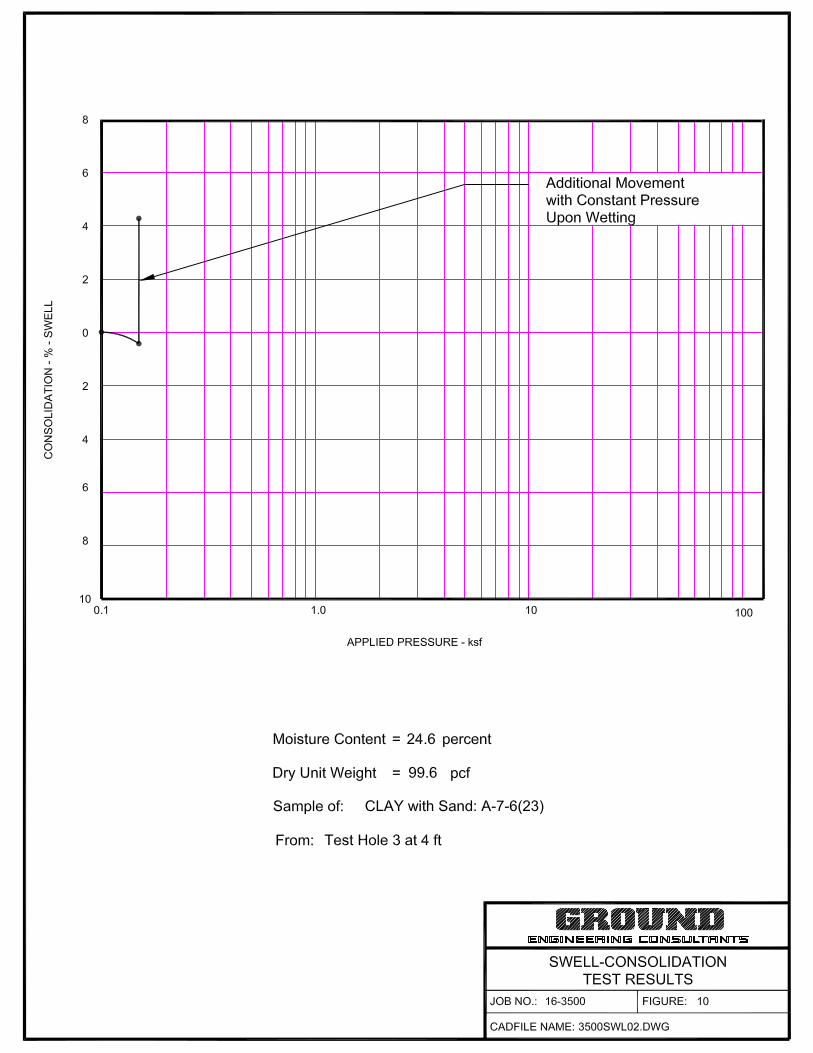
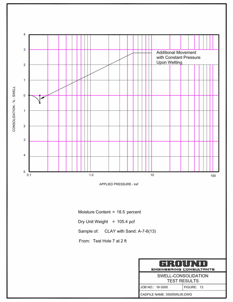
Swell-Consolidation Testing indicated a potential for heave and consolidation in the
tested on-site materials tested. Swells of approximately 0.1 to 4.7 percent and
consolidations of approximately 0.1 to 0.5 percent were measured upon wetting against
a surcharge load of 150 psf (City of Thornton – Standards and Specifications, 503.7A.j).
Swell-consolidation test results are provided in Table 1 and Figures 9 through 20.
Groundwater was encountered in Test Holes 1 and 22 at the time of drilling at depths of
approximately 14½ and 18 feet below existing grade, respectively. The test holes were
backfilled immediately following drilling operations for safety. Groundwater levels should

High School #3 Off-site Improvements Brighton School District 27J
Thornton, Colorado Final Submittal
Revised
Job No. 16-3500 GROUND Engineering Consultants, Inc. Page 5
be anticipated to fluctuate, however, in response to annual and longer-term cycles of
precipitation, applied irrigation, and surface drainage.
CULVERT FOUNDATION SYSTEM
According to representatives of the project team, a culvert system may be installed
within Yosemite Street. Additionally, a cast-in-place concrete structure that will
accommodate a PRV for the proposed waterline will also be installed. Final
depths/elevations of the proposed culvert/concrete system or actual construction type
were unknown at the time of this report preparation. This information should be provided
to GROUND for review in order to evaluate the parameters provided herein.
Based on the results of our field and laboratory testing program, a potential for heave is
present in the site earth materials. Even so, our experience suggests that these
structures often have a greater tolerance for movement and when movement does
occur, the movement often tends to not appear as severe as that observed in other
types of structures, i.e., a building. Additionally, up to approximately 6 feet of existing fill
material was observed within the test holes, likely associated with the existing utility
trenches. Deeper depths of man-made fill may exist on-site. It is unknown if these fill
soils were documented during placement (compaction testing). Ideally, undocumented
fill material should be removed and replaced as properly compacted fill. However, as
indicated above, we understand that these types of structures are often more tolerant to
movement and the removal and replacement of observed fill soils are often deemed
impractical or uneconomical. Therefore, the proposed culvert/concrete structures may
be constructed using a shallow foundation system bearing on the fill soils or native earth
materials provided that at least 12 inches of subgrade beneath the proposed structures
are scarified and re-compacted as outlined in the Project Earthwork section of this
report. The City of Thornton should be consulted as to whether they possess istorical
data regarding these fill soils.
Groundwater was encountered in Test Holes 1 and 22 at the time of drilling at depths of
approximately 14½ and 18 feet below existing grade, respectively. Even so,
groundwater levels may fluctuate with the season. Therefore, depending on final
grades, groundwater may be encountered in deep excavations. The contractor should
be prepared to dewater the excavation during construction.

High School #3 Off-site Improvements Brighton School District 27J
Thornton, Colorado Final Submittal
Revised
Job No. 16-3500 GROUND Engineering Consultants, Inc. Page 6
The geotechnical parameters indicated below may be used for design of shallow
foundations for the proposed culvert/concrete structure.
Geotechnical Parameters for Shallow Foundation Design
(1) Footings/foundations bearing on at least 12 inches of properly moisture-density
treated materials may be designed for an allowable soil bearing pressure of 2,000
psf. Based on this allowable bearing pressure, we anticipate post-construction
settlements to be on the order of 1 inch.
Compression of the bearing soils for the provided allowable bearing pressure is
estimated to be 1 inch, based on an assumption of drained foundation conditions.
If foundation soils are subjected to an increase/fluctuation in moisture content, the
effective bearing capacity will be reduced and greater post-construction
movements than those estimated above may result.
This estimate of foundation movement from direct compression of the foundation
soils is in addition to movements from expansive soils heave and/or collapse of
hydro-compressive soils.
To reduce differential settlements between foundation elements, footing loads
should be as uniform as possible. Differentially loaded footings will settle
differentially.
(2) Footings/foundations should have a minimum dimension of 14 or more inches.
Actual dimensions, however, should be determined by the Structural Engineer,
based on the design loads.
(3) Footings/foundations should bear at an elevation 3 or more feet below the lowest
adjacent exterior finish grades to have adequate soil cover for frost protection
(4) The lateral resistance of footings/foundations will be developed as sliding
resistance of the footing bottoms on the foundation materials and by passive soil
pressure against the sides of the footings/foundations. Sliding friction at the
bottom of footings/foundations may be taken as 0.27 times the vertical dead load.

High School #3 Off-site Improvements Brighton School District 27J
Thornton, Colorado Final Submittal
Revised
Job No. 16-3500 GROUND Engineering Consultants, Inc. Page 7
(5) Connections of all types must be flexible and/or adjustable to accommodate the
anticipated, post-construction movements.
Shallow Foundation Construction
(6) The contractor should take adequate care when making excavations not to
compromise the bearing or lateral support for nearby improvements.
(7) Care should be taken when excavating the foundations to avoid disturbing the
supporting materials particularly in excavating the last few inches.
(8) All unsuitable including but not limited to saturated, near-saturated, muck-like or
yielding bearing materials exposed at the bottom of the excavation should be
excavated and replaced with properly moisture conditioned and compacted fill in
accordance with the Project Earthwork section of this report, or the excavation
deepened to adequate earth materials. Use of controlled low strength material
(CLSM), i.e., a lean sand-cement slurry, flowable fill, or a similar material in lieu of
compacted soil backfill in these locations may be beneficial where access is
restricted or when it can be placed more rapidly than properly compacted soil fill.
As stated, placement of a layer of crushed rock at the bottom of the excavation to
achieve and maintain a stable working platform should be considered. A layer of
geotextile between the crushed rock and on-site soils should also be considered.
(9) Foundation-supporting soils may be disturbed or deform excessively under the
wheel loads of heavy construction vehicles as the excavations approach footing
bearing levels. Construction equipment should be as light as possible to limit
development of this condition. The movement of vehicles over proposed
foundation areas should be restricted.
(10) All foundation subgrade should be properly cleaned/compacted so no loose soils
remain, prior to placement of concrete.
(11) As necessary, fill placed against the sides of the footings/foundations should be
properly compacted in accordance with the Project Earthwork section of this report.

High School #3 Off-site Improvements Brighton School District 27J
Thornton, Colorado Final Submittal
Revised
Job No. 16-3500 GROUND Engineering Consultants, Inc. Page 8
LATERAL EARTH PRESSURES
The at-rest, active, and passive earth pressures in terms of equivalent fluid unit weight
for the on-site backfill are summarized on the table below. The use of passive pressure
under a saturated condition is not recommended. The values or the on-site sand
material and clay/silt were approximated utilizing a unit weight of 124 pcf and a phi angle
of 22 degrees. The values below are unfactored. Appropriate factors of safety should
be included in the design.
Lateral Earth Pressures (Equivalent Fluid Unit Weights)
Material Type Water
Condition
At-Rest
(pcf)
Active
(pcf)
Passive
(pcf)
Friction
Coefficient
On-Site Sand and Clay Backfill
Drained 77 56 270 0.27
Submerged 100 90 - 0.27
Structure Backfill
Drained 55 35 400 0.45
Submerged 90 80 -- 0.45
WATER-SOLUBLE SULFATES
The concentrations of water-soluble sulfates measured in selected samples obtained
from the test holes were approximately 0.01 to 0.34 percent. Such concentrations of
water-soluble sulfates represent a negligible to severe environment for sulfate attack on
concrete exposed to these materials. Degrees of attack are based on the scale of
‘negligible,’ ‘moderate,’ ‘severe’ and ‘very severe’ as described in the “Design and
Control of Concrete Mixtures,” published by the Portland Cement Association (PCA).
The Colorado Department of Transportation (CDOT) utilizes a corresponding scale with
4 classes of severity of sulfate exposure (Class 0 to Class 3) as described in the
published table below.

High School #3 Off-site Improvements Brighton School District 27J
Thornton, Colorado Final Submittal
Revised
Job No. 16-3500 GROUND Engineering Consultants, Inc. Page 9
REQUIREMENTS TO PROTECT AGAINST DAMAGE TO
CONCRETE BY SULFATE ATTACK FROM EXTERNAL SOURCES OF SULFATE
Severity of Sulfate
Exposure
Water-Soluble Sulfate (SO4)
In Dry Soil (%)
Sulfate (SO4) In Water
(ppm)
Water Cementitious
Ratio (maximum)
Cementitious Material
Requirements
Class 0 0.00 to 0.10 0 to 150 0.45 Class 0
Class 1 0.11 to 0.20 151 to 1500 0.45 Class 1
Class 2 0.21 to 2.00 1501 to 10,000 0.45 Class 2
Class 3 2.01 or greater 10,001 or greater 0.40 Class 3
Based on our test results and PCA and CDOT guidelines, GROUND recommends use of
sulfate-resistant cement in all concrete exposed to site soil and bedrock, conforming to
one of the following Class 2 requirements:
(1) ASTM C 150 Type V with a minimum of a 20 percent substitution of Class F fly
ash by weight
(2) ASTM C 150 Type II or III with a minimum of a 20 percent substitution of Class F
fly ash by weight. The Type II or III cement shall have no more than 0.040
percent expansion at 14 days when tested according ASTM C 452
(3) ASTM C 1157 Type HS; Class C fly ash shall not be substituted for cement.
(4) ASTM C 1157 Type MS plus Class F fly ash where the blend has less than 0.05
percent expansion at 6 months or 0.10 percent expansion at 12 months when
tested according to ASTM C 1012.
(5) A blend of Portland cement meeting ASTM C 150 Type II or III with a minimum of
20 percent Class F fly ash by weight, where the blend has less than 0.05 percent
expansion at 6 months or 0.10 percent expansion at 12 months when tested
according to ASTM C 1012.
(6) ASTM C 595 Type IP(HS); Class C fly ash shall not be substituted for cement.

High School #3 Off-site Improvements Brighton School District 27J
Thornton, Colorado Final Submittal
Revised
Job No. 16-3500 GROUND Engineering Consultants, Inc. Page 10
When fly ash is used to enhance sulfate resistance, it shall be used in a proportion
greater than or equal to the proportion tested in accordance to ASTM C 1012, shall be
the same source, and it shall have a calcium oxide content no more than 2.0 percent
greater than the fly ash tested according to ASTM C 1012.
All concrete exposed to site soil and bedrock should have a minimum compressive
strength of 4,500 psi.
The contractor should be aware that certain concrete mix components affecting sulfate
resistance including, but not limited to, the cement, entrained air, and fly ash, can affect
workability, set time, and other characteristics during placement, finishing and curing.
The contractor should develop mix(es) for use in project concrete which are suitable with
regard to these construction factors, as well as sulfate resistance. A reduced, but still
significant, sulfate resistance may be acceptable to the owner, in exchange for desired
construction characteristics.
SOIL CORROSIVITY
The degree of risk for corrosion of metals in soils commonly is considered to be in two
categories: corrosion in undisturbed soils and corrosion in disturbed soils. The potential
for corrosion in undisturbed soil is generally low, regardless of soil types and conditions,
because it is limited by the amount of oxygen that is available to create an electrolytic
cell. In disturbed soils, the potential for corrosion typically is higher, but is strongly
affected by soil chemistry and other factors.
A preliminary corrosivity analysis was performed to provide a general assessment of the
potential for corrosion of ferrous metals installed in contact with earth materials at the
site, based on the conditions existing at the time of GROUND’s evaluation. Soil
chemistry and physical property data including pH, reduction-oxidation (redox) potential,
and sulfides content were obtained. Test results are summarized on Table 2.
pH Where pH is less than 4.0, soil serves as an electrolyte; the pH range of about 6.5 to
7.5 indicates soil conditions that are optimum for sulfate reduction. In the pH range
above 8.5, soils are generally high in dissolved salts, yielding a low soil resistivity
(AWWA, 2010). Testing indicated pH values of approximately 8.7 to 9.0.

High School #3 Off-site Improvements Brighton School District 27J
Thornton, Colorado Final Submittal
Revised
Job No. 16-3500 GROUND Engineering Consultants, Inc. Page 11
Reduction-Oxidation testing indicated negative potentials: -102 to -118 millivolts. Such
low potentials typically create a more corrosive environment.
Sulfide Reactivity testing for the presence of sulfides indicated ‘trace’, ‘negative’ and
‘positive’ results. The presence of sulfides in the site soils also suggests a more
corrosive environment.
Soil Resistivity In order to assess the “worst case” for mitigation planning, samples of
materials retrieved from the test holes were tested for resistivity in the in the laboratory,
after being saturated with water, rather than in the field. Resistivity also varies inversely
with temperature. Therefore, the laboratory measurements were made at a controlled
temperature.
Measurements of electrical resistivity indicated values of approximately 778 to 4,693
ohm-centimeters in samples of the site earth materials. The following table presents the
relationship between soil resistivity and a qualitative corrosivity rating (ASM, 2003)1.
Corrosivity Ratings Based on Soil Resistivity
Soil Resistivity (ohm-cm)
Corrosivity Rating
>20,000 Essentially non-corrosive
10,000 – 20,000 Mildly corrosive
5,000 – 10,000 Moderately corrosive
3,000 – 5,000 Corrosive
1,000 – 3,000 Highly corrosive
<1,000 Extremely corrosive
Corrosivity Assessment The American Water Works Association (AWWA, 20102) has
developed a point system scale used to predict corrosivity. The scale is intended for
protection of ductile iron pipe but is valuable for project steel selection. When the scale
equals 10 points or higher, protective measures for ductile iron pipe are suggested. The
1 ASM International, 2003, Corrosion: Fundamentals, Testing and Protection, ASM Handbook, Volume 13A. 2 American Water Works Association ANSI/AWWA C105/A21.5-05 Standard.

High School #3 Off-site Improvements Brighton School District 27J
Thornton, Colorado Final Submittal
Revised
Job No. 16-3500 GROUND Engineering Consultants, Inc. Page 12
AWWA scale (Table A.1 Soil-test Evaluation) is presented below. The soil characteristics
refer to the conditions at and above pipe installation depth.
Table A.1 Soil-test Evaluation
Soil Characteristic / Value Points
Resistivity <1,500 ohm-cm ..........................................................................................… 10 1,500 to 1,800 ohm-cm ................................................................……......…. 8 1,800 to 2,100 ohm-cm .............................................................................…. 5 2,100 to 2,500 ohm-cm ...............................................................................… 2 2,500 to 3,000 ohm-cm .................................................................................. 1 >3,000 ohm-cm ................................................................................… 0 pH 0 to 2.0 ............................................................................................................ 5 2.0 to 4.0 ......................................................................................................... 3 4.0 to 6.5 ......................................................................................................... 0 6.5 to 7.5 ......................................................................................................... 0 * 7.5 to 8.5 ......................................................................................................... 0 >8.5 .......................................................................................................... 3
Redox Potential < 0 (negative values) ....................................................................................... 5 0 to +50 mV ................................................................................................…. 4 +50 to +100 mV ............................................................................................… 3½ > +100 mV ............................................................................................... 0
Sulfide Content Positive ........................................................................................................…. 3½ Trace .............................................................................................................… 2 Negative .......................................................................................................…. 0
Moisture Poor drainage, continuously wet ..................................................................…. 2 Fair drainage, generally moist ....................................................................… 1 Good drainage, generally dry ........................................................................ 0
* If sulfides are present and low or negative redox-potential results (< 50 mV) are
obtained, add three points for this range.
The redox potential of a soil is significant, because the most common sulfate-reducing
bacteria can only live in anaerobic conditions. A negative redox potential indicates
anaerobic conditions in which sulfate reducers thrive. A positive sulfide reaction reveals
a potential problem caused by sulfate-reducing bacteria. Anaerobic conditions are
regarded as potentially corrosive.

High School #3 Off-site Improvements Brighton School District 27J
Thornton, Colorado Final Submittal
Revised
Job No. 16-3500 GROUND Engineering Consultants, Inc. Page 13
Based on a maximum possible score of 25.5 using the AWWA method, the value of 10
for the use of corrosion protection, and scores of approximately 11.5 to 21.5 in the on-
site soil, the soil appears to comprise a moderate to highly corrosive environment for
buried metals.
If additional information is needed regarding soil corrosivity, the American Water Works
Association or a Corrosion Engineer should be contacted. It should be noted, however,
that changes to the site conditions during construction, such as the import of other soils,
or the intended or unintended introduction of off-site water, may significantly alter
corrosion potential.
PROJECT EARTHWORK
The following information is for private improvements; public roadways or utilities
should be constructed in accordance with City of Thornton standards.
Prior to earthwork construction, existing vegetation, topsoil, asphalt, concrete, and other
deleterious materials should be removed and disposed of off-site. Relic underground
utilities, if encountered, should be abandoned in accordance with applicable regulations,
removed as necessary, and capped at the margins of the property. The Geotechnical
Engineer should be contracted to test the excavation backfill during placement.
Topsoil should not be incorporated into fill placed on the site. Instead, topsoil should be
stockpiled during initial grading operations for placement in areas to be landscaped or
for other approved uses.
Existing Fill Soils: Man-made fill was encountered in some of the test holes at the time
of drilling. Actual contents and composition of all aspects of the man-made fill materials
are not known; therefore, some of the excavated man-made fill materials may not be
suitable for replacement as backfill. The Geotechnical Engineer should be retained
during site excavations to observe the excavated fill materials and provide guidance for
its suitability for reuse.
Imported Fill Materials: If it is necessary to import material to the site, the imported
soils should be free of organic material, and other deleterious materials. Imported
material should consist of relatively impervious soils that have less than 60
High School #3 Off-site Improvements Brighton School District 27J
Thornton, Colorado Final Submittal
Revised
Job No. 16-3500 GROUND Engineering Consultants, Inc. Page 14
percent passing the No. 200 Sieve and should have a plasticity index less than 20.
Representative samples of the materials proposed for import should be tested and
approved prior to transport to the site.
Use of Existing Native Soils: Overburden soils that are free of trash, organic material,
construction debris, and other deleterious materials are suitable, in general, for
placement as compacted fill. Organic materials should not be incorporated into project
fills.
Fragments of rock, cobbles, and inert construction debris (e.g., concrete or asphalt)
larger than 3 inches in maximum dimension will require special handling and/or
placement to be incorporated into project fills. In general, such materials should be
placed as deeply as possible in the project fills. A Geotechnical Engineer should be
consulted regarding appropriate information for usage of such materials on a case-by-
case basis when such materials have been identified during earthwork. Standard
parameters that likely will be generally applicable can be found in Section 203 of the
current CDOT Standard Specifications for Road and Bridge Construction.
Reconditioning Expansive Earth Materials: Expansive materials were observed in the
test holes and include swell potentials up to 4.7 percent, measured against a 150 psf
surcharge pressure. Higher swell potentials could exist on-site. In the Denver Metro
area, these materials have been excavated and replaced with variable success due to
the natural properties of highly expansive materials as well as poorly controlled materials
processing and varying placement techniques. The Client, Owner, and Contractor must
understand that expansive bedrock will require additional processing including but not
limited to stockpile moisture conditioning and multiple sub-excavations including partial
to complete removal of previously moisture conditioned and compacted fill materials.
The following parameters will not eliminate post-construction movement associated with
structures/utility trenches/improvements constructed on expansive soils and bedrock, but
may tend to make movements more uniform.
Excavated materials will require a well-coordinated effort to moisture treat, process,
place, and compact properly. In-place bedrock deposits were hard to relatively resistant
and relatively dry, and require a significant volume of water to be mixed into the
excavated material to bring them to a uniform moisture content from optimum to 3

High School #3 Off-site Improvements Brighton School District 27J
Thornton, Colorado Final Submittal
Revised
Job No. 16-3500 GROUND Engineering Consultants, Inc. Page 15
percent above the optimum prior to compaction. The daily moisture content in the tested
fill should be between 2 and 3 percent above the optimum as an additional requirement.
Bedrock fragments should be reduced so as to achieve a soil-like mass. Adequate
watering, and compaction equipment that aids in breaking down the material (e.g., a
Caterpillar 825 compactor-roller), likely will be needed. Excavated bedrock will require
additional moisture conditioning and processing in an open area outside of utility
trenches prior to placement as backfill.
Fill Platform Preparation: Prior to filling, the top 8 to 12 inches of in-place materials on
which fill soils will be placed should be scarified, moisture conditioned and properly
compacted in accordance with the parameters below to provide a uniform base for fill
placement.
If surfaces to receive fill expose loose, wet, soft or otherwise deleterious material,
additional material should be excavated, or other measures taken to establish a firm
platform for filling. The surfaces to receive fill must be effectively stable prior to
placement of fill.
Wet, Soft or Unstable Subgrades Where wet, soft or unstable subgrades are
encountered, the contractor should establish a firm, stable platform for fill placement and
compaction. Excavation of the unstable soils and replacing them with coarse granular
material or relatively dry soil, possibly together with the use of stabilization geo-textile or
geo-grid, may be necessary to achieve stability. Whereas the stabilization approach
should be determined by the contractor, GROUND offers the alternatives below for
consideration. Proof-rolling can be beneficial for identifying unstable areas.
Replacement of the existing subgrade soils with clean, coarse, aggregate (e.g.,
crushed rock or “pit run” materials) or with road base. Excavation and replacement
to a depth of 1 to 2 feet commonly is sufficient, but greater depths may be necessary
to establish a stable surface.
On very weak subgrades, an 18- to 24-inch “pioneer” lift that is not well compacted
may be beneficial to stabilize the subgrade. Where this approach is employed,
however, additional settlements of ½ inch may result.
High School #3 Off-site Improvements Brighton School District 27J
Thornton, Colorado Final Submittal
Revised
Job No. 16-3500 GROUND Engineering Consultants, Inc. Page 16
Where coarse, aggregate alone does not appear sufficient to provide stable
conditions, it can be beneficial to place a layer of stabilization geo-textile or geo-grid
(e.g., Tencate Mirafi® HP370 or RS 380i, or Tensar® BX 1100) at the base of the
aggregate section.
The stabilization geo-textile / geo-grid should be selected based on the aggregate
proposed for use. It should be placed and lapped in accordance with the
manufacturer’s recommendations.
Geo-textile or geo-grid products can be disturbed by the wheels or tracks of
construction vehicles. We suggest that appropriate care be taken to maintain the
effectiveness of the system. Placement of a layer of aggregate over the geo-textile /
geo-grid prior to allowing vehicle traffic over it can be beneficial in this regard.
When a given remedial approach has been selected, GROUND recommends
constructing a test section to evaluate the effectiveness of the approach prior to use over
a larger area.
Fill Placement: Fill materials should be thoroughly mixed to achieve a uniform moisture
content, placed in uniform lifts not exceeding 8 inches in loose thickness, and properly
compacted.
Soils that classify as A-1 through A-3 should be compacted to 95 percent of the
maximum modified Proctor dry density at moisture contents within 2 percent of optimum
moisture content as determined by AASHTO T-180.
Soils that classify as A-4 through A-7 should be compacted to 95 percent of the
maximum standard Proctor density at moisture contents from 1 percent below to 3
percent above the optimum as determined by AASHTO T-99.
No fill materials should be placed, worked, rolled while they are frozen, thawing, or
during poor/inclement weather conditions.
Care should be taken with regard to achieving and maintaining proper moisture contents
during placement and compaction. Materials that are not properly moisture conditioned
may exhibit significant pumping, rutting, and deflection at moisture contents near

High School #3 Off-site Improvements Brighton School District 27J
Thornton, Colorado Final Submittal
Revised
Job No. 16-3500 GROUND Engineering Consultants, Inc. Page 17
optimum and above. The contractor should be prepared to handle soils of this type,
including the use of chemical stabilization, if necessary.
Compaction areas should be kept separate, and no lift should be covered by another
until relative compaction and moisture content within the suggested ranges are obtained.
EXCAVATION CONSIDERATIONS
The test holes for the subsurface exploration were excavated to the depths indicated by
means of truck-mounted, flight auger drilling equipment. Practical drill rig refusal was not
encountered at the time of subsurface exploration, however, very hard and resistant
bedrock was encountered. We anticipate that excavation into the bedrock will be slow
even with conventional, heavy duty, excavating equipment, and will entail greater than
typical wear on the equipment used.
Some excavation difficulties are anticipated, however. These may include the following:
The presence of claystone formational bedrock. Significant processing and
moisture conditioning of claystone formational bedrock may be needed prior to
incorporation in project fills (see Project Earthwork section). It is possible that
sandstone bedrock possessing varying degrees of cementation may also be
encountered.
Temporary, un-shored excavation slopes up to 10 feet in height be cut no steeper than
1½:1 (horizontal : vertical) in the site soils in the absence of seepage. Sloughing on the
slope faces should be anticipated at this angle. Local conditions encountered during
construction, such as groundwater seepage and loose sand, will require flatter slopes.
Stockpiling of materials should not be permitted closer to the tops of temporary slopes
than 5 feet or a distance equal to the depth of the excavation, whichever is greater.
Should site constraints prohibit the use of the slope angles, temporary shoring should be
used. The shoring should be designed to resist the lateral earth pressure exerted by
building, traffic, equipment, and stockpiles.
Groundwater was encountered in Test Holes 1 and 22 at the time of drilling at depths of
approximately 14½ and 18 feet below existing grade, respectively. Therefore,

High School #3 Off-site Improvements Brighton School District 27J
Thornton, Colorado Final Submittal
Revised
Job No. 16-3500 GROUND Engineering Consultants, Inc. Page 18
groundwater may be encountered during utility excavations and should be anticipated by
the contractor. A properly designed and installed de-watering system may be required
during the construction. The risk of slope instability will be significantly increased in
areas of seepage along the excavation slopes. If seepage or groundwater is
encountered during excavation, the Geotechnical Engineer should evaluate the
conditions and provide additional parameters as appropriate.
Good surface drainage should be provided around temporary excavation slopes to direct
surface runoff away from the slope faces. A properly designed drainage swale should
be provided at the top of the excavations. In no case should water be allowed to pond at
the site. Slopes should also be protected against erosion. Erosion along the slopes will
result in sloughing and could lead to a slope failure.
Excavations in which personnel will be working must comply with all OSHA Standards
and Regulations. The Contractor’s “responsible person” should evaluate the soil
exposed in the excavations as part of the Contractor’s safety procedures. GROUND has
provided the information above solely as a service to the Client, and is not assuming
responsibility for construction site safety or the Contractor’s activities.
UTILITY PIPE INSTALLATION AND BACKFILLING
As stated, groundwater was encountered in Test Holes 1 and 22 at the time of drilling at
depths of approximately 14½ and 18 feet below existing grade, respectively. Therefore,
groundwater could potentially be a significant factor in utility excavations in some areas,
and should be anticipated by the contractor. The contractor should be prepared to
dewater the excavation to provide a stable platform prior to the installation of the pipe
and bedding materials.
Pipe Support: The bearing capacity of the site soils appeared adequate, in general, for
support of anticipated water lines. The pipe + water are less dense than the soils which
will be displaced for installation. Therefore, GROUND anticipates no significant pipe
settlements in these materials where properly bedded.
Excavation bottoms may expose soft, loose or otherwise deleterious materials, including
debris. Firm materials may be disturbed by the excavation process. All such unsuitable
materials should be excavated and replaced with properly compacted fill. Areas allowed

High School #3 Off-site Improvements Brighton School District 27J
Thornton, Colorado Final Submittal
Revised
Job No. 16-3500 GROUND Engineering Consultants, Inc. Page 19
to pond water will require excavation and replacement with properly compacted fill. The
contractor should take particular care to ensure adequate support near pipe joints which
are less tolerant of extensional strains.
Where thrust blocks are needed, they may be designed for an allowable passive soil
pressure of 270 psf per foot of embedment, to a maximum of 2,700 psf. Sliding friction
at the bottom of thrust blocks may be taken as 0.27 times the vertical dead load.
Trench Backfilling: Some settlement of compacted soil trench backfill materials should
be anticipated, even where all the backfill is placed and compacted correctly. Typical
settlements are on the order of 1 to 2 percent of fill thickness. However, the need to
compact to the lowest portion of the backfill must be balanced against the need to
protect the pipe from damage from the compaction process. Some thickness of backfill
may need to be placed at compaction levels lower than specified (or smaller compaction
equipment used together with thinner lifts) to avoid damaging the pipe. Protecting the
pipe in this manner can result in somewhat greater surface settlements. Therefore,
although other alternatives may be available, the following options are presented for
consideration:
Controlled Low Strength Material: Because of these limitations, we suggest backfilling
the entire depth of the trench (both bedding and common backfill zones) with “controlled
low strength material” (CLSM), i.e., a lean, sand-cement slurry, “flowable fill,” or similar
material along all trench alignment reaches with low tolerances for surface settlements.
We suggest that CLSM used as pipe bedding and trench backfill exhibit a 28-day
unconfined compressive strength between 50 to 200 psi so that re-excavation is not
unusually difficult.
Placement of the CLSM in several lifts or other measures likely will be necessary to
avoid ‘floating’ the pipe. Measures also should be taken to maintain pipe alignment
during CLSM placement.
Compacted Soil Backfilling: Where compacted soil backfilling is employed, using the
site soils or similar materials as backfill, the risk of backfill settlements entailed in the
selection of this higher risk alternative must be anticipated and accepted by the
Client/Owner.

High School #3 Off-site Improvements Brighton School District 27J
Thornton, Colorado Final Submittal
Revised
Job No. 16-3500 GROUND Engineering Consultants, Inc. Page 20
We anticipate that the on-site soils excavated from trenches will be suitable, in general,
for use as common trench backfill within the above-described limitations. Backfill soils
should be free of vegetation, organic debris and other deleterious materials. Fragments
of rock, cobbles, and inert construction debris (e.g., concrete or asphalt) coarser than 3
inches in maximum dimension should not be incorporated into trench backfills.
If it is necessary to import material for use as backfill, the imported soils should be free
of vegetation, organic debris, and other deleterious materials. Imported material should
consist of relatively impervious soils that have less than 60 percent passing the No. 200
Sieve and should have a plasticity index of less than 20. Representative samples of the
materials proposed for import should be tested and approved prior to transport to the
site.
Soils placed for compaction as trench backfill should be conditioned to a relatively
uniform moisture content, placed and compacted in accordance with the Project
Earthwork section of this report.
Pipe Bedding: Pipe bedding materials, placement and compaction should meet the
specifications of the pipe manufacturer and applicable municipal standards. Bedding
should be brought up uniformly on both sides of the pipe to reduce differential loadings.
As discussed above, we suggest the use of CLSM or similar material in lieu of granular
bedding and compacted soil backfill where the tolerance for surface settlement is low.
(Placement of CLSM as bedding to at least 12 inches above the pipe can protect the
pipe and assist construction of a well-compacted conventional backfill although possibly
at an increased cost relative to the use of conventional bedding.)
If a granular bedding material is specified, it is our opinion that with regard to potential
migration of fines into the pipe bedding, design and installation follow ASTM D2321. If
the granular bedding does not meet filter criteria for the enclosing soils, then non-woven
filter fabric (e.g., Mirafi® 140N, or the equivalent) should be placed around the bedding to
reduce migration of fines into the bedding which can result in severe, local surface
settlements. Where this protection is not provided, settlements can develop/continue
several months or years after completion of the project. In addition, clay or concrete cut-
off walls should be installed to interrupt the granular bedding section to reduce the rates

High School #3 Off-site Improvements Brighton School District 27J
Thornton, Colorado Final Submittal
Revised
Job No. 16-3500 GROUND Engineering Consultants, Inc. Page 21
and volumes of water transmitted along the sewer alignment which can contribute to
migration of fines.
If granular bedding is specified, the contractor should not anticipate that significant
volumes of on-site soils will be suitable for that use. Materials proposed for use as pipe
bedding should be tested by a geotechnical engineer for suitability prior to use.
Imported materials should be tested and approved by a geotechnical engineer prior to
transport to the site.
FROST HEAVE
Based on the results of the field exploration as well as the laboratory testing, it appears
that silty soils requiring special design considerations for the purpose of addressing frost
heave are present at the project. According to the US Army Corps of Engineers, the
soils on-site classify as F3 materials. Therefore, even if surface drainage is effective,
the likelihood of movement of pavements, flatwork and other hardscaping as a result of
frost heave, is relatively moderate to high.
PAVEMENT SECTIONS
A pavement section is a layered system designed to distribute concentrated traffic loads
to the subgrade. Performance of the pavement structure is directly related to the
physical properties of the subgrade soils and traffic loadings.
Standard practice in pavement design describes a typical flexible pavement section as a
“20-year” design pavement. However, most pavements will not remain in satisfactory
condition without routine maintenance and rehabilitation procedures performed
throughout the life of the pavement.
Pavement sections for the internal roadways were developed in general accordance with
the design guidelines and procedures of the American Association of State Highway and
Transportation Officials (AASHTO), the Colorado Department of Transportation (CDOT),
City of Thornton pavement construction practice. We understand that the proposed
roadways will be designated as Collector (Minor) roadways.

High School #3 Off-site Improvements Brighton School District 27J
Thornton, Colorado Final Submittal
Revised
Job No. 16-3500 GROUND Engineering Consultants, Inc. Page 22
Subgrade Materials
Based on the results of our field and laboratory studies, subgrade materials encountered
in our test holes consisted predominantly of fill material that was comprised of sand and
clay/silt. These materials were classified typically as A-6 to A-7-6 soils in accordance
with the AASHTO classification system, with Group Index values from 2 to 25 in the
upper 4 feet.
GROUND collected composite bulk samples from the test holes. Based on the results of
the Proctor testing, GROUND utilized the “worst case” for use in the design of the
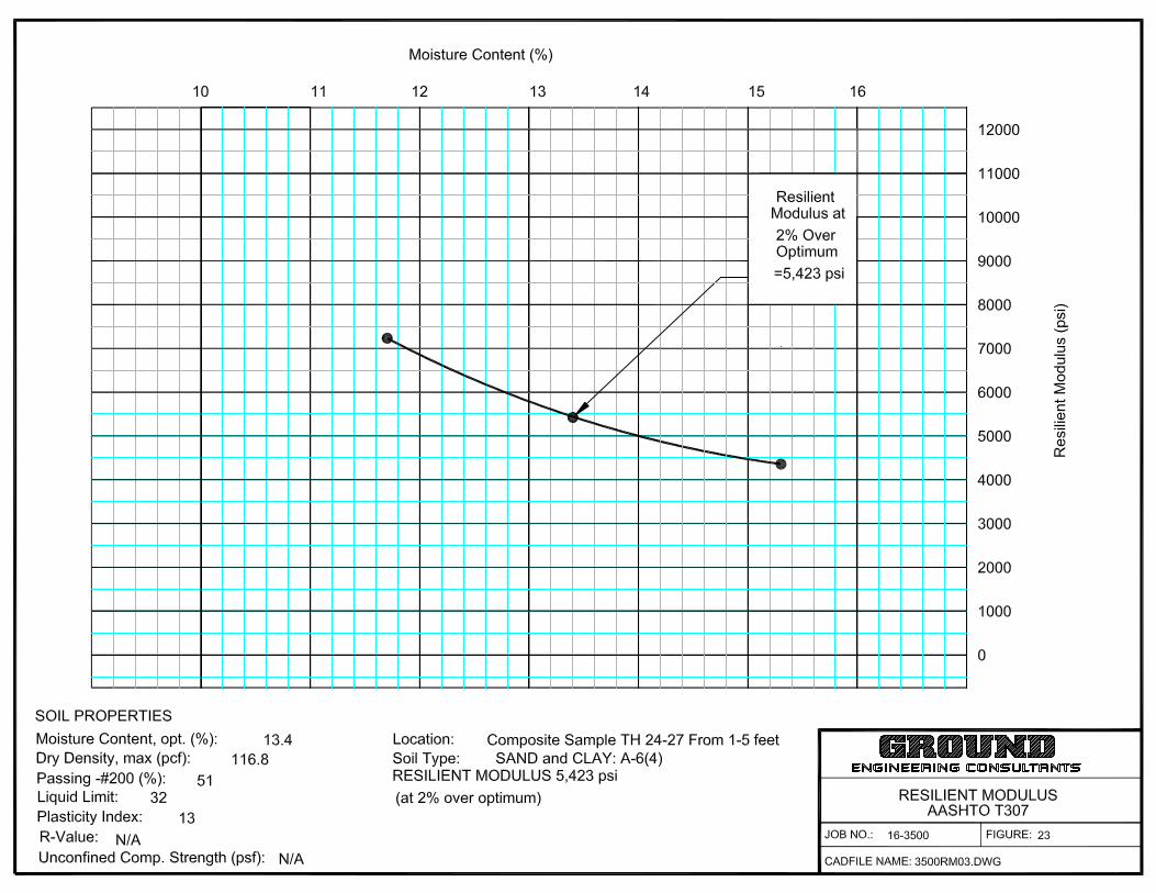
pavement. Resilient Modulus (MR) testing (AASHTO T-307) was performed on the
composite samples of the subgrade materials encountered along the alignments.
Typically, the R-value, unconfined compressive strength, California Bearing Ratio (CBR),
or other index properties of subgrade materials have been obtained and the resilient
modulus obtained only by correlation. However, due to the variability in the correlations,
subjecting representative samples of the subgrade to the actual resilient modulus test is
the most accurate way to determine soil support characteristics for use in pavement
design.
A dynamic load test, the resilient modulus measures the elastic rebound stiffness of
flexible pavement materials, base courses and subgrades under repeated loading. The
loading cycles were applied under various confining and deviatoric stresses as specified
in AASTHO T-294. The material was compacted to approximately 95 percent of
maximum dry density at approximately optimum moisture content, and at 2 percent and
4 percent above the optimum, based on AASHTO T-99 (the “standard Proctor”) for
cohesive soils.
The resilient modulus of a material at 2 percent above optimum moisture content
typically is used for the pavement design for fine-grained soils that classify as A-4, A-6,
or A-7. According to our testing results, resilient modulus values ranging from
approximately 5,178 to 5,817 psi were determined for the on-site materials. For the
purpose of this study, a resilient modulus value of 5,178 psi was utilized.
It is important to note that significant decreases in soil support as quantified by the
resilient modulus have been observed as the moisture content increases above the
optimum. Therefore, pavements that are not properly drained may experience a loss of
the soil support and subsequent reduction in pavement life.

High School #3 Off-site Improvements Brighton School District 27J
Thornton, Colorado Final Submittal
Revised
Job No. 16-3500 GROUND Engineering Consultants, Inc. Page 23
Design Traffic
GROUND was provided existing and projected traffic information developed by Stolfus &
Associates, Inc., for Yosemite Street between 136th Avenue and Riverdale Road for the
“SD 27J High School #3” project, in a revised study dated March 18, 2016. We
understand that the proposed improvements will be constructed in 2017 (build year).
Based on this information, vehicle traffic values are indicated in the table below for
Yosemite Street, 136th Avenue, and Riverdale Road (south and east of Yosemite Street).
Additionally, as provided in the traffic study, a total of 2 to 4 percent trucks with a 60 / 40
percent split between single unit trucks and combination trucks was assumed based on
CDOT data for SH-22A. Using this information, the corresponding lane configuration
value of 0.60 for roadways consisting of 2 lanes (136th Avenue and Riverdale Road) and
3 lanes (Yosemite Street) and applicable design procedures, resulted in equivalent 18-
kip single axle loading (ESAL) value as provided in the table below.
Roadway Section ADT (Vehicles per
Day)
Truck Percentage
(%)
ESAL (20-year)
Yosemite Street 5,700 6 510,205
136th Avenue 8,800 4 1,011,703
Riverdale Road south of Yosemite
9,100 2 582,883
Riverdale Road east of Yosemite
5,300 2 339,482
If design traffic loadings differ significantly from these values, the pavement sections
provided below should be re-evaluated. The City of Thornton should be provided with
this report in order to review the above traffic values.
Pavement Design
The soil resilient modulus and the indicated ESAL value were used to determine the
required design structural number for the project pavements. The required structural
number was then used to develop pavement sections. Pavement designs for flexible

High School #3 Off-site Improvements Brighton School District 27J
Thornton, Colorado Final Submittal
Revised
Job No. 16-3500 GROUND Engineering Consultants, Inc. Page 24
pavements were based on the DARWin™ computer program that solves the 1993
AASHTO pavement design equations. The resilient modulus and the design ESAL
values, as indicated above, along with a Reliability Level of 85 percent and a
serviceability index of 2.0 (City of Thornton – Standards and Specifications, Table 500-5)
were used in the pavement section designs for the proposed construction. The required
structural number was then used to develop pavement sections. Structural coefficients
of 0.44 and 0.14 were used for new hot bituminous asphalt (HBA) and aggregate base
course, respectively (City of Thornton, Table 500-6). The pavement design calculations
are presented in Appendix A.
Minimum Pavement Sections
Roadway
Minimum Full Depth Asphalt Section (inches Asphalt)
Minimum Composite
Section (inches Asphalt over
Aggregate Base Course)
Yosemite Street 7½ 5 / 8
136th Avenue 8½ 6 / 8
Riverdale Road south of Yosemite 7½ 5 / 8
Riverdale Road east of Yosemite 7 5 / 6
Pavement Properties
Hot Bituminous Asphalt (HBA): The asphalt pavement shall consist of a bituminous plant
mix composed of a mixture of high quality aggregate and bituminous material, which
meets the requirements of a job-mix formula established by a qualified engineer. The
asphalt materials used should be based on a SuperPave Gyratory Design Revolution
(NDES) of 75, for both the lower lift(s) and surface layer, per City of Thornton (Table 500-
10). Grading SG or S is acceptable for the lower lift(s) using PG 64-22 asphalt cement
binder and grading SX is acceptable for the surface layer using PG 64-28 asphalt
cement binder. Please note that the pavement binders could be adjusted depending on
the market condition at the time of construction. Alternate binding types should be
submitted to the City of Thornton for review and approval prior to construction.

High School #3 Off-site Improvements Brighton School District 27J
Thornton, Colorado Final Submittal
Revised
Job No. 16-3500 GROUND Engineering Consultants, Inc. Page 25
Pavement lift thicknesses should be between 3 to 4 inches (SG) and 2¼ to 3½ inches
(S) for the lower lift(s), depending on the material type selected, and 2 to 3 inches for the
top lift (SX). Ultimately, NDES and asphalt cement binder requirements are those of City
of Thornton and may differ from those presented herein.
Aggregate Base Course (ABC): The aggregate base material should meet the criteria of
CDOT Class 6 aggregate base course. Base course should be placed in uniform lifts
not exceeding 8 inches in loose thickness and compacted to at least 95 percent of the
maximum dry density a uniform moisture contents within 3 percent of the optimum as
determined by ASTM D1557 / AASHTO T-180, the “modified Proctor.”
Pavement Subgrade Preparation
According to City of Thornton specifications, swelling (expansive) soils greater than 2
percent under a 150 psf surcharge (flexible pavements) shall not be permitted (for use)
without subgrade treatment. Based on our test results, a swell potential of 4.7 percent
was obtained from our testing within the proposed alignment of 136th Avenue (Test Hole
3 at a depth of approximately 4 feet). Therefore, subgrade treatment to mitigate the
swell potential in this area will be necessary based on the City of Thornton
specifications. A specific overexcavation/moisture-density treatment depth is not
specified by the City of Thornton. It is GROUND’s opinion that the roadway alignment
from approximately 200 feet in each direction from Test Hole 3 should be removed to a
depth of approximately 5 feet and replaced in a moisture-density treated manner.
Greater extents may be necessary based on the actual subsurface conditions
encountered/observed during construction. Based on our test results, swell potentials
less than 2 percent were obtained from our testing of samples obtained from the
remainder of 136th Avenue, Yosemite Street, and Riverdale Road. Therefore, mitigation
to address expansion potentials in all other areas does not appear to be necessary.
Even so, the upper 12 inches should be scarified and recompacted in accordance with
the Project Earthwork section of this report. The City of Thornton should be consulted
regarding the desired subgrade preparation measures.
Immediately prior to paving, the subgrade should be proof rolled with a heavily loaded,
pneumatic tired vehicle. Areas that show excessive deflection during proof rolling should
be excavated and replaced and/or stabilized. Areas allowed to pond prior to paving will

High School #3 Off-site Improvements Brighton School District 27J
Thornton, Colorado Final Submittal
Revised
Job No. 16-3500 GROUND Engineering Consultants, Inc. Page 26
require significant re-working prior to proof-rolling. All subgrade preparation must
ultimately comply with roadway inspection, testing, and construction procedures outlined
by the governing municipality.
The proposed alignment(s) contains existing shallow-buried utilities. The contractor
should be aware that additional care should be taken when working in these areas. In
the event the subgrade materials are significantly disturbed or require moisture-density
treatment, recompaction over/adjacent to these utilities may be very difficult, possibly
resulting in the utilization of concrete or flow fill in order to properly prepare the subgrade
area for paving.
Pavement subgrade materials should be compacted in accordance with the Project
Earthwork section of this report. Subgrade preparation should extend the full width of
the pavement from back-of-curb to back-of-curb and also extend under the adjacent
sidewalks, exterior flatwork, etc.
Additional Observations
The collection and diversion of surface drainage away from paved areas is extremely
important to satisfactory performance of the pavements. The subsurface and surface
drainage systems should be carefully designed to ensure removal of the water from
paved areas and subgrade soils. Allowing surface waters to pond on pavements will
cause premature pavement deterioration. Where topography, site constraints or other
factors limit or preclude adequate surface drainage, pavements should be provided with
edge drains to reduce loss of subgrade support.
GROUND’s experience indicates that longitudinal cracking is common in asphalt-
pavements generally parallel to the interface between the asphalt and concrete
structures such as curbs, gutters or drain pans. Distress of this type is likely to occur
even where the subgrade has been prepared properly and the asphalt has been
compacted properly.
The standard care of practice in pavement design describes the flexible pavement
section as a “20-year” design pavement; however, most pavements will not remain in
satisfactory condition without routine, preventive maintenance and rehabilitation
procedures performed throughout the life of the pavement. Preventive pavement

High School #3 Off-site Improvements Brighton School District 27J
Thornton, Colorado Final Submittal
Revised
Job No. 16-3500 GROUND Engineering Consultants, Inc. Page 27
treatments are surface rehabilitation and operations applied to improve or extend the
functional life of a pavement. These treatments preserve, rather than improve, the
structural capacity of the pavement structure. In the event the existing pavement is not
structurally sound, the preventive maintenance will have no long-lasting effect.
Therefore, a routine maintenance program to seal cracks, repair distressed areas, and
perform thin overlays throughout the life of the pavement is suggested.
A crack sealing and fog seal / chip seal program should be performed on flexible
pavements on a regular basis. After approximately 8 to 10 years, patching, additional
crack sealing, and asphalt overlay may be required. Prior to future overlays, it is
important that all transverse and longitudinal cracks be sealed with a flexible, rubberized
crack sealant in order to reduce the potential for propagation of the crack through the
overlay. Concrete pavements will likely require grinding and localized panel
replacement. Traffic volumes that exceed the values utilized by this report will likely
necessitate the need of pavement maintenance practices on a schedule of shorter
timeframe than that stated above. The greatest benefit of preventive maintenance is
achieved by placing the treatments on sound pavements that have little or no distress.
CLOSURE
Geotechnical Review: The author of this report should be retained to review project
plans and specifications to evaluate whether they comply with the intent of the
parameters in this report. The review should be requested in writing.
The geotechnical opinions presented in this report are contingent upon observation and
testing of project earthworks by representatives of GROUND. If another geotechnical
consultant is selected to provide materials testing, then that consultant must assume all
responsibility for the geotechnical aspects of the project by concurring in writing with the
conclusions in this report, or by providing alternative parameters.
Materials Testing: The Client should consider retaining a Geotechnical Engineer to
perform materials testing during construction. The performance of such testing or lack
thereof, in no way alleviates the burden of the contractor or subcontractor from
constructing in a manner that conforms to applicable project documents and industry
standards. The contractor or pertinent subcontractor is ultimately responsible for

High School #3 Off-site Improvements Brighton School District 27J
Thornton, Colorado Final Submittal
Revised
Job No. 16-3500 GROUND Engineering Consultants, Inc. Page 28
managing the quality of their work; furthermore, testing by the geotechnical engineer
does not preclude the contractor from obtaining or providing whatever services they
deem necessary to complete the project in accordance with applicable documents.
Limitations: This report has been prepared for Brighton School District 27J as it
pertains to the construction of proposed roadways and improvements as described
herein. It may not contain sufficient information for other parties or other purposes. The
owner or any prospective buyer relying upon this report must be made aware of and
must agree to the terms, conditions, and liability limitations outlined in the proposal.
In addition, GROUND has assumed that project construction will commence by
Fall/Winter 2016. Any changes in project plans or schedule should be brought to the
attention of the Geotechnical Engineer, in order that the geotechnical parameters may
be re-evaluated and, as necessary, modified.
The geotechnical conclusions in this report relied upon subsurface exploration at a
limited number of exploration points, as shown in Figure 1, as well as the means and
methods described herein. Subsurface conditions were interpolated between and
extrapolated beyond these locations. It is not possible to guarantee the subsurface
conditions are as indicated in this report. Actual conditions exposed during construction
may differ from those encountered during site exploration.
If during construction, surface, soil, bedrock, or groundwater conditions appear to be at
variance with those described herein, the Geotechnical Engineer should be advised at
once, so that re-evaluation of the parameters may be made in a timely manner. In
addition, a contractor who relies upon this report for development of his scope of work or
cost estimates may find the geotechnical information in this report to be inadequate for
his purposes or find the geotechnical conditions described herein to be at variance with
his experience in the greater project area. The contractor is responsible for obtaining
the additional geotechnical information that is necessary to develop his workscope and
cost estimates with sufficient precision. This includes current depths to groundwater,
etc.
The materials present on-site are stable at their natural moisture content, but may
change volume or lose bearing capacity or stability with changes in moisture content.

High School #3 Off-site Improvements Brighton School District 27J
Thornton, Colorado Final Submittal
Revised
Job No. 16-3500 GROUND Engineering Consultants, Inc. Page 29
Performance of the proposed pavement and improvements will depend on
implementation of the conclusions in this report and on proper maintenance after
construction is completed. Because water is a significant cause of volume change in
soils and rock, allowing moisture infiltration may result in movements, some of which will
exceed estimates provided herein and should therefore be expected by the owner.
The materials present on-site are stable at their natural moisture content, but may
change volume or lose bearing capacity or stability with changes in moisture content.
ALL DEVELOPMENT CONTAINS INHERENT RISKS. It is important that ALL aspects
of this report, as well as the estimated performance (and limitations with any such
estimations) of proposed project improvements are understood by the Client, Project
Owner (if different), or properly conveyed to any future owner(s). Utilizing these
parameters for planning, design, and/or construction constitutes understanding and
acceptance of conclusions or information provided herein, potential risks, associated
improvement performance, as well as the limitations inherent within such estimations. If
any information referred to herein is not well understood, it is imperative for the Client,
Owner (if different), or anyone using this report to contact the author or a company
principal immediately.
This report was prepared in accordance with generally accepted soil and foundation
engineering practice in the project area at the date of preparation. GROUND makes no
warranties, either expressed or implied, as to the professional data, opinions or
conclusions contained herein. Because of numerous considerations that are beyond
GROUND’s control, the economic or technical performance of the project cannot be
guaranteed in any respect.

High School #3 Off-site Improvements Brighton School District 27J
Thornton, Colorado Final Submittal
Revised
Job No. 16-3500 GROUND Engineering Consultants, Inc. Page 30
GROUND appreciates the opportunity to complete this portion of the project and
welcomes the opportunity to provide the Owner with a cost proposal for construction
observation and materials testing prior to construction commencement.
Sincerely, GROUND Engineering Consultants, Inc.
Amy Crandall, P.E. Reviewed by Jason A. Smith, REM, P.E.


Sample of: Fill: Sandy CLAY
GRADATION TEST RESULTSJOB NO.: 16-3500
FIGURE: 24
58%
From: TH-2 at 3 feet Liquid Limit 42 Plasticity Index 24
Gravel 1% Sand 41% Silt and Clay
3" 2" 1.5" 1" 3/4" 1/2" 3/8" #4 #10 #16 #40 #50 #100 #200
0
10
20
30
40
50
60
70
80
90
100
0.0010.010.1110100
PE
RC
EN
T P
AS
SIN
G
DIAMETER OF PARTICLE IN MILLIMETERS
SIEVE ANALYSIS: ASTM C 136 with C 117 or D 1140
Sieve Openings: U.S Standard Sieves
HYDROMETER ANALYSIS: ASTM D 422
Timed ReadingsCO
BBLE
GRAVELCoarse Fine
SANDCoarse Medium
SILT
CLAYFine

Sample of:
GRADATION TEST RESULTSJOB NO.: 16-3500
FIGURE: 25
67%
From: TH-5 at 3 feet Liquid Limit 55 Plasticity Index 25
Gravel 2% Sand 31% Silt and Clay
3" 2" 1.5" 1" 3/4" 1/2" 3/8" #4 #10 #16 #40 #50 #100 #200
0
10
20
30
40
50
60
70
80
90
100
0.0010.010.1110100
PE
RC
EN
T P
AS
SIN
G
DIAMETER OF PARTICLE IN MILLIMETERS
SIEVE ANALYSIS: ASTM C 136 with C 117 or D 1140
Sieve Openings: U.S Standard Sieves
HYDROMETER ANALYSIS: ASTM D 422
Timed ReadingsCO
BBLE
GRAVELCoarse Fine
SANDCoarse Medium
SILT
CLAYFine

Sample of: Sandy CLAY
GRADATION TEST RESULTSJOB NO.: 16-3500
FIGURE: 26
67%
From: TH-8 at 3 feet Liquid Limit 41 Plasticity Index 16
Gravel 0% Sand 33% Silt and Clay
3" 2" 1.5" 1" 3/4" 1/2" 3/8" #4 #10 #16 #40 #50 #100 #200
0
10
20
30
40
50
60
70
80
90
100
0.0010.010.1110100
PE
RC
EN
T P
AS
SIN
G
DIAMETER OF PARTICLE IN MILLIMETERS
SIEVE ANALYSIS: ASTM C 136 with C 117 or D 1140
Sieve Openings: U.S Standard Sieves
HYDROMETER ANALYSIS: ASTM D 422
Timed ReadingsCO
BBLE
GRAVELCoarse Fine
SANDCoarse Medium
SILT
CLAYFine

Sample of: Fill: Sandy CLAY
GRADATION TEST RESULTSJOB NO.: 16-3500
FIGURE: 27
58%
From: TH-11 at 3 feet Liquid Limit 31 Plasticity Index 13
Gravel 1% Sand 41% Silt and Clay
3" 2" 1.5" 1" 3/4" 1/2" 3/8" #4 #10 #16 #40 #50 #100 #200
0
10
20
30
40
50
60
70
80
90
100
0.0010.010.1110100
PE
RC
EN
T P
AS
SIN
G
DIAMETER OF PARTICLE IN MILLIMETERS
SIEVE ANALYSIS: ASTM C 136 with C 117 or D 1140
Sieve Openings: U.S Standard Sieves
HYDROMETER ANALYSIS: ASTM D 422
Timed ReadingsCO
BBLE
GRAVELCoarse Fine
SANDCoarse Medium
SILT
CLAYFine
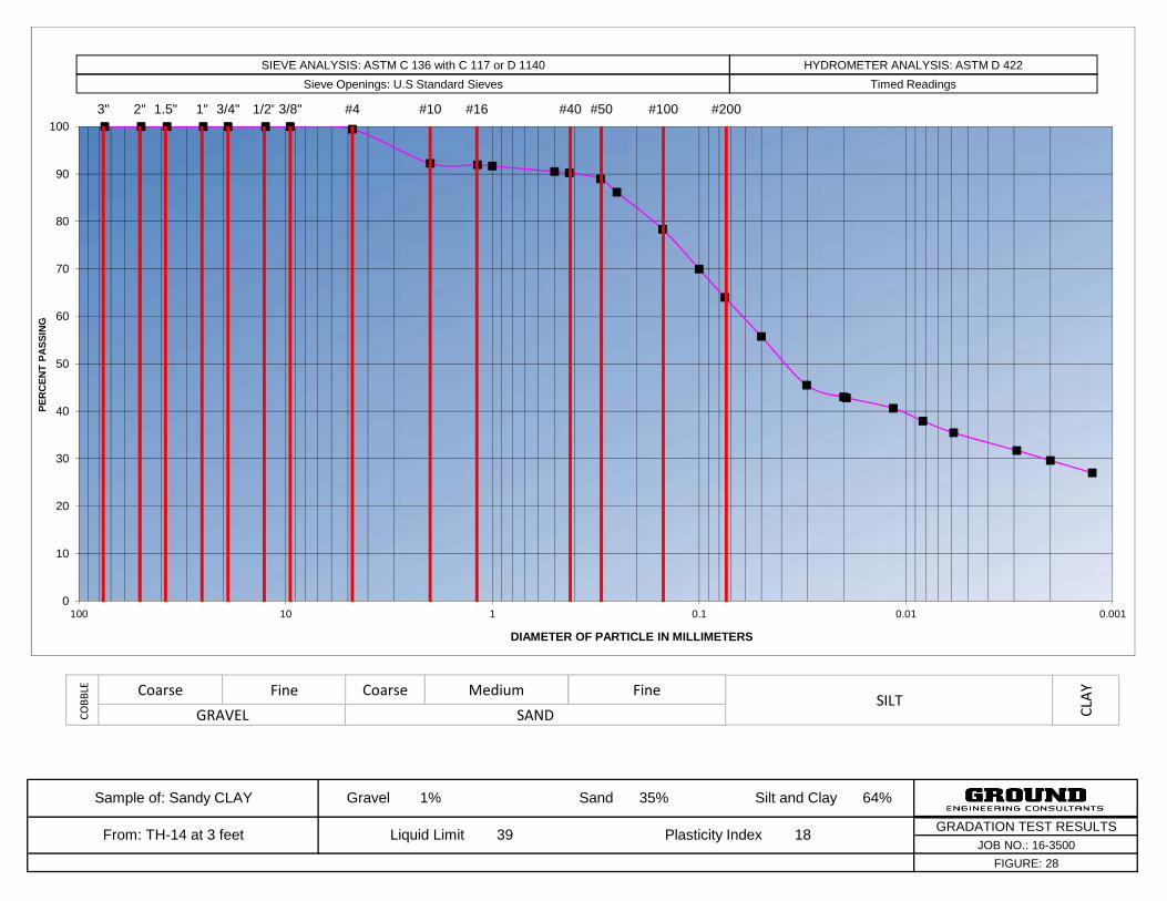
Sample of: Sandy CLAY
GRADATION TEST RESULTSJOB NO.: 16-3500
FIGURE: 28
64%
From: TH-14 at 3 feet Liquid Limit 39 Plasticity Index 18
Gravel 1% Sand 35% Silt and Clay
3" 2" 1.5" 1" 3/4" 1/2" 3/8" #4 #10 #16 #40 #50 #100 #200
0
10
20
30
40
50
60
70
80
90
100
0.0010.010.1110100
PE
RC
EN
T P
AS
SIN
G
DIAMETER OF PARTICLE IN MILLIMETERS
SIEVE ANALYSIS: ASTM C 136 with C 117 or D 1140
Sieve Openings: U.S Standard Sieves
HYDROMETER ANALYSIS: ASTM D 422
Timed ReadingsCO
BBLE
GRAVELCoarse Fine
SANDCoarse Medium
SILT
CLAYFine

Sample of: CLAY with Sand
GRADATION TEST RESULTSJOB NO.: 16-3500
FIGURE: 29
76%
From: TH-17 at 2 feet Liquid Limit 42 Plasticity Index 20
Gravel 1% Sand 23% Silt and Clay
3" 2" 1.5" 1" 3/4" 1/2" 3/8" #4 #10 #16 #40 #50 #100 #200
0
10
20
30
40
50
60
70
80
90
100
0.0010.010.1110100
PE
RC
EN
T P
AS
SIN
G
DIAMETER OF PARTICLE IN MILLIMETERS
SIEVE ANALYSIS: ASTM C 136 with C 117 or D 1140
Sieve Openings: U.S Standard Sieves
HYDROMETER ANALYSIS: ASTM D 422
Timed ReadingsCO
BBLE
GRAVELCoarse Fine
SANDCoarse Medium
SILT
CLAYFine

Sample of: Sandy CLAY
GRADATION TEST RESULTSJOB NO.: 16-3500
FIGURE: 30
63%
From: TH-24 at 9 feet Liquid Limit 30 Plasticity Index 13
Gravel 1% Sand 36% Silt and Clay
3" 2" 1.5" 1" 3/4" 1/2" 3/8" #4 #10 #16 #40 #50 #100 #200
0
10
20
30
40
50
60
70
80
90
100
0.0010.010.1110100
PE
RC
EN
T P
AS
SIN
G
DIAMETER OF PARTICLE IN MILLIMETERS
SIEVE ANALYSIS: ASTM C 136 with C 117 or D 1140
Sieve Openings: U.S Standard Sieves
HYDROMETER ANALYSIS: ASTM D 422
Timed ReadingsCO
BBLE
GRAVELCoarse Fine
SANDCoarse Medium
SILT
CLAYFine

COMPACTION TEST REPORTCurve No.: 3063
Project No.: Date:
Project:Client:Location: 136th Ave, TH 1-13, 0-5'
Sample Number: 3063
Remarks:
MATERIAL DESCRIPTION
Description:
Classifications - USCS: AASHTO:
Nat. Moist. = Sp.G. =
Liquid Limit = Plasticity Index =
% < No.200 =
ROCK CORRECTED TEST RESULTS
FigureGround Engineering Consultants, Inc.
16-3500 1/15/16
Brighton School #275
Sand and Clay and Silt and Gravel
(SC)g A-4(0)
26 10
36.7 %
Maximum dry density = 120 pcf
Optimum moisture = 12 %
31
Dry
den
sity
, pcf
70
80
90
100
110
120
130
140
Water content, %
0 5 10 15 20 25 30 35 40
100% SATURATION CURVESFOR SPEC. GRAV. EQUAL TO:
2.82.72.6
Test specification: AASHTO T 99-01 Method A Standard AASHTO T 224-01 Oversize Correction Applied to Final Results

COMPACTION TEST REPORTCurve No.: 3064
Project No.: Date:
Project:Client:Location: TH-14-23, Yosemite St
Sample Number: 3064
Remarks:
MATERIAL DESCRIPTION
Description:
Classifications - USCS: AASHTO:
Nat. Moist. = Sp.G. =
Liquid Limit = Plasticity Index =
% < No.200 =
ROCK CORRECTED TEST RESULTS
FigureGround Engineering Consultants, Inc.
16-3500 1/15/16
Brighton School #275
Sand, Silt, Clay and Gravel
s(CL)g A-6(4)
41 21
60.3 %
Maximum dry density = 127 pcf
Optimum moisture = 9 %
32
Dry
den
sity
, pcf
70
80
90
100
110
120
130
140
Water content, %
0 5 10 15 20 25 30 35 40
100% SATURATION CURVESFOR SPEC. GRAV. EQUAL TO:
2.82.72.6
Test specification: AASHTO T 99-01 Method A Standard AASHTO T 224-01 Oversize Correction Applied to Final Results

COMPACTION TEST REPORTCurve No.: 3088
Project No.: Date:
Project:Client:Location: TH-24-27
Sample Number: 3088
Remarks:
MATERIAL DESCRIPTION
Description:
Classifications - USCS: AASHTO:
Nat. Moist. = Sp.G. =
Liquid Limit = Plasticity Index =
% < No.200 =
ROCK CORRECTED TEST RESULTS
FigureGround Engineering Consultants, Inc.
16-3500 1/21/16
Brighton School #275
Clays, Sand and Silt
s(CL) A-6(4)
32 13
51.3 %
Maximum dry density = 117 pcf
Optimum moisture = 13 %
33
Dry
den
sity
, pcf
70
80
90
100
110
120
130
140
Water content, %
0 5 10 15 20 25 30 35 40
100% SATURATION CURVESFOR SPEC. GRAV. EQUAL TO:
2.82.72.6
Test specification: AASHTO T 99-01 Method A Standard AASHTO T 224-01 Oversize Correction Applied to Final Results

TABLE 1SUMMARY OF LABORATORY TEST RESULTS
Sample Location Natural Natural Percent Atterberg Limits Percent USCS AASHTOTest Moisture Dry Passing Liquid Plasticity Swell Classifi- Classifi- Soil orHole Depth Content Density Gravel Sand Silt Clay No. 200 Limit Index (150 psf Surcharge cation cation Bedrock TypeNo. (feet) (%) (pcf) (%) (%) (%) (%) Sieve Pressure) (GI)
1 4 21.2 99.6 - - - - 76 35 15 0.1% CL A-6(10) CLAY with Sand
2 3 15.0 112.5 1 41 31 27 58 42 24 - CL A-7-6(11) Fill: Sandy CLAY
3 4 24.6 99.6 - - - - 85 51 24 4.7% CH A-7-6(23) CLAY with Sand
3 9 17.4 111.7 - - - - 89 49 25 - CL A-7-6(24) CLAYSTONE
4 3 19.5 107.7 - - - - 74 38 17 - CL A-6(12) CLAY with Sand
4 13 17.6 109.1 - - - - 92 47 20 - CL A-7-6(21) CLAYSTONE
5 3 23.7 96.4 2 31 22 45 67 55 25 1.7% MH A-7-5(17) Sandy SILT
6 4 17.9 92.5 - - - - 64 39 16 - CL A-6(9) Sandy CLAY
6 9 18.5 110.4 - - - - 91 36 17 0.8% CL A-6(15) CLAYSTONE
7 2 18.5 105.4 - - - - 71 43 20 0.5% CL A-7-6(13) CLAY with Sand
8 3 18.1 103.5 0 33 29 38 67 41 16 - CL A-7-6(10) Sandy CLAY
9 4 21.3 103.8 - - - - 81 43 19 - CL A-7-6(16) CLAY with Sand
9 9 11.0 121.6 - - - - 44 33 15 - SC A-6(3) Clayey SAND
10 4 16.3 107.5 - - - - 61 34 14 - CL A-6(6) Sandy CLAY
11 3 13.6 111.8 1 41 33 25 58 31 13 - CL A-6(5) Fill: Sandy CLAY
12 4 17.5 108.1 - - - - 65 38 19 - CL A-6(10) Fill: Sandy CLAY
12 9 16.6 113.0 - - - - 86 47 25 4.5% CL A-7-6(23) CLAYSTONE
13 4 20.8 103.1 - - - - 74 39 17 0.7% CL A-6(12) CLAY with Sand
14 3 15.6 110.9 1 35 34 30 64 39 18 - CL A-6(10) Sandy CLAY
15 4 17.2 107.3 - - - - 69 37 16 - CL A-6(10) Sandy CLAY
15 9 16.7 106.7 - - - - 67 35 15 - CL A-6(8) Sandy CLAY
16 3 17.1 109.4 - - - - 70 40 17 - CL A-6(11) Sandy CLAY
16 18 21.5 89.5 - - - - 74 53 29 - CH A-7-6(22) CLAYSTONE with Sand
Hydrometer Testing

TABLE 1SUMMARY OF LABORATORY TEST RESULTS
Sample Location Natural Natural Percent Atterberg Limits Percent USCS AASHTOTest Moisture Dry Passing Liquid Plasticity Swell Classifi- Classifi- Soil orHole Depth Content Density Gravel Sand Silt Clay No. 200 Limit Index (150 psf Surcharge cation cation Bedrock TypeNo. (feet) (%) (pcf) (%) (%) (%) (%) Sieve Pressure) (GI)
Hydrometer Testing
17 2 15.7 111.1 1 23 37 39 76 42 20 -0.5% CL A-7-6(15) CLAY with Sand
18 4 14.4 118.3 - - - - 57 34 17 - CL A-6(7) Fill: Sandy CLAY
18 9 20.0 105.0 - - - - 76 46 23 - CL A-7-6(17) CLAY with Sand
19 4 16.0 113.4 - - - - 69 36 15 - CL A-6(9) Fill: Sandy CLAY
20 3 17.0 103.3 - - - - 85 38 17 -0.1% CL A-6(14) CLAY with Sand
21 4 13.8 115.2 - - - - 68 33 14 - CL A-6(8) Fill: Sandy CLAY
21 9 18.2 108.4 - - - - 84 47 25 -0.1% CL A-7-6(22) CLAYSTONE with Sand
22 3 23.3 89.7 - - - - 77 58 31 - CH A-7-6(25) CLAY with Sand
23 2 19.5 106.5 - - - - 84 43 21 0.5% CL A-7-6(18) CLAY with Sand
24 4 13.7 107.6 - - - - 55 33 15 - CL A-6(5) Sandy CLAY
24 9 20.6 100.6 1 35 39 24 63 30 13 - CL A-6(6) Sandy CLAY
25 3 18.2 102.5 - - - - 70 38 16 0.5% CL A-6(10) Sandy CLAY
26 2 12.1 112.8 - - - - 40 33 15 - SC A-6(2) Fill: Clayey SAND
26 7 22.2 101.7 - - - - 87 57 29 - CH A-7-6(29) CLAYSTONE
27 2 15.0 113.9 - - - - 64 33 16 - CL A-6(8) Fill: Sandy CLAY
Resilient Modulus (psi)
1-13 1-5 12.2* 120.1* - - - - 37 26 10 5,817 SC A-4(0) Clayey SAND
14-23 1-5 9.3* 127.1* - - - - 60 41 21 5,178 CL A-7-6(10) SAND and CLAY
24-27 1-5 13.4* 116.8* - - - - 51 32 13 5,423 CL A-6(4) SAND and CLAY
* Indicates optimum moisture content and maximum standard Proctor density (ASTM D-698) Job No. 16-3500

TABLE 2SUMMARY OF SOIL CORROSION TEST RESULTS
Sample Location Water Redox Sulfides USCSTest Soluble pH Potential Content Resistivity Classifi- Soil orHole Depth Sulfates cation Bedrock TypeNo. (feet) (%) (mV) (ohm-cm)
2 3 <0.01 8.8 -105 Positive 4,693 CL Sandy CLAY
4 13 0.11 9.0 -111 Negative 1,211 CL CLAY
6 4 0.11 8.9 -106 Positive 778 CL Sandy CLAY
7 2 0.11 8.7 -102 Trace 1,341 CL CLAY with Sand
12 4 0.34 8.9 -108 Trace 1,132 CL Sandy CLAY
15 4 0.20 9.0 -118 Trace 1,149 CL Sandy CLAY
19 4 0.13 9.0 -105 Trace 2,102 CL Sandy CLAY
27 2 0.04 9.0 -112 Positive 1,906 CL Sandy CLAY
Job No. 16-3500

Page 1
1993 AASHTO Pavement Design
DARWin Pavement Design and Analysis System
A Proprietary AASHTOWareComputer Software Product
Network Administrator
Flexible Structural Design Module
Brighton School District 27J - High School #3Yosemite Street
Flexible Structural Design
18-kip ESALs Over Initial Performance Period 510,205 Initial Serviceability 4.5 Terminal Serviceability 2 Reliability Level 85 %Overall Standard Deviation 0.44 Roadbed Soil Resilient Modulus 5,178 psiStage Construction 1
Calculated Design Structural Number 3.22 in
Specified Layer Design
Layer
Material Description
StructCoef.(Ai)
DrainCoef.(Mi)
Thickness(Di)(in)
Width
(ft)
Calculated
SN (in)1 Full Depth Asphalt 0.44 1 7.5 - 3.30
Total - - - 7.50 - 3.30
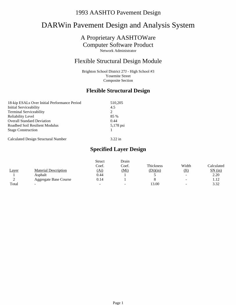
Page 1
1993 AASHTO Pavement Design
DARWin Pavement Design and Analysis System
A Proprietary AASHTOWareComputer Software Product
Network Administrator
Flexible Structural Design Module
Brighton School District 27J - High School #3Yosemite Street
Composite Section
Flexible Structural Design
18-kip ESALs Over Initial Performance Period 510,205 Initial Serviceability 4.5 Terminal Serviceability 2 Reliability Level 85 %Overall Standard Deviation 0.44 Roadbed Soil Resilient Modulus 5,178 psiStage Construction 1
Calculated Design Structural Number 3.22 in
Specified Layer Design
Layer
Material Description
StructCoef.(Ai)
DrainCoef.(Mi)
Thickness(Di)(in)
Width
(ft)
Calculated
SN (in)1 Asphalt 0.44 1 5 - 2.202 Aggregate Base Course 0.14 1 8 - 1.12
Total - - - 13.00 - 3.32

Page 1
1993 AASHTO Pavement Design
DARWin Pavement Design and Analysis System
A Proprietary AASHTOWareComputer Software Product
Network Administrator
Flexible Structural Design Module
Brighton School District 27J - High School #3136th Avenue
Flexible Structural Design
18-kip ESALs Over Initial Performance Period 1,011,703 Initial Serviceability 4.5 Terminal Serviceability 2 Reliability Level 85 %Overall Standard Deviation 0.44 Roadbed Soil Resilient Modulus 5,178 psiStage Construction 1
Calculated Design Structural Number 3.55 in
Specified Layer Design
Layer
Material Description
StructCoef.(Ai)
DrainCoef.(Mi)
Thickness(Di)(in)
Width
(ft)
Calculated
SN (in)1 Full Depth Asphalt 0.44 1 8.5 - 3.74
Total - - - 8.50 - 3.74

Page 1
1993 AASHTO Pavement Design
DARWin Pavement Design and Analysis System
A Proprietary AASHTOWareComputer Software Product
Network Administrator
Flexible Structural Design Module
Brighton School District 27J - High School #3136th Avenue
Composite Section
Flexible Structural Design
18-kip ESALs Over Initial Performance Period 1,011,703 Initial Serviceability 4.5 Terminal Serviceability 2 Reliability Level 85 %Overall Standard Deviation 0.44 Roadbed Soil Resilient Modulus 5,178 psiStage Construction 1
Calculated Design Structural Number 3.55 in
Specified Layer Design
Layer
Material Description
StructCoef.(Ai)
DrainCoef.(Mi)
Thickness(Di)(in)
Width
(ft)
Calculated
SN (in)1 Asphalt 0.44 1 6 - 2.642 Aggregate Base Course 0.14 1 8 - 1.12
Total - - - 14.00 - 3.76

Page 1
1993 AASHTO Pavement Design
DARWin Pavement Design and Analysis System
A Proprietary AASHTOWareComputer Software Product
Network Administrator
Flexible Structural Design Module
Brighton School District 27J - High School #3Riverdale Road South of Yosemite
Flexible Structural Design
18-kip ESALs Over Initial Performance Period 582,883 Initial Serviceability 4.5 Terminal Serviceability 2 Reliability Level 85 %Overall Standard Deviation 0.44 Roadbed Soil Resilient Modulus 5,178 psiStage Construction 1
Calculated Design Structural Number 3.28 in
Specified Layer Design
Layer
Material Description
StructCoef.(Ai)
DrainCoef.(Mi)
Thickness(Di)(in)
Width
(ft)
Calculated
SN (in)1 Full Depth Asphalt 0.44 1 7.5 - 3.30
Total - - - 7.50 - 3.30

Page 1
1993 AASHTO Pavement Design
DARWin Pavement Design and Analysis System
A Proprietary AASHTOWareComputer Software Product
Network Administrator
Flexible Structural Design Module
Brighton School District 27J - High School #3Riverdale Road South of Yosemite
Composite Section
Flexible Structural Design
18-kip ESALs Over Initial Performance Period 582,883 Initial Serviceability 4.5 Terminal Serviceability 2 Reliability Level 85 %Overall Standard Deviation 0.44 Roadbed Soil Resilient Modulus 5,178 psiStage Construction 1
Calculated Design Structural Number 3.28 in
Specified Layer Design
Layer
Material Description
StructCoef.(Ai)
DrainCoef.(Mi)
Thickness(Di)(in)
Width
(ft)
Calculated
SN (in)1 Asphalt 0.44 1 5 - 2.202 Aggregate Base Course 0.14 1 8 - 1.12
Total - - - 13.00 - 3.32

Page 1
1993 AASHTO Pavement Design
DARWin Pavement Design and Analysis System
A Proprietary AASHTOWareComputer Software Product
Network Administrator
Flexible Structural Design Module
Brighton School District 27J - High School #3Riverdale Road East of Yosemite Street
Flexible Structural Design
18-kip ESALs Over Initial Performance Period 339,482 Initial Serviceability 4.5 Terminal Serviceability 2 Reliability Level 85 %Overall Standard Deviation 0.44 Roadbed Soil Resilient Modulus 5,178 psiStage Construction 1
Calculated Design Structural Number 3.03 in
Specified Layer Design
Layer
Material Description
StructCoef.(Ai)
DrainCoef.(Mi)
Thickness(Di)(in)
Width
(ft)
Calculated
SN (in)1 Full Depth Asphalt 0.44 1 7 - 3.08
Total - - - 7.00 - 3.08

Page 1
1993 AASHTO Pavement Design
DARWin Pavement Design and Analysis System
A Proprietary AASHTOWareComputer Software Product
Network Administrator
Flexible Structural Design Module
Brighton School District 27J - High School #3Riverdale Road East of Yosemite
Composite Section
Flexible Structural Design
18-kip ESALs Over Initial Performance Period 339,482 Initial Serviceability 4.5 Terminal Serviceability 2 Reliability Level 85 %Overall Standard Deviation 0.44 Roadbed Soil Resilient Modulus 5,178 psiStage Construction 1
Calculated Design Structural Number 3.03 in
Specified Layer Design
Layer
Material Description
StructCoef.(Ai)
DrainCoef.(Mi)
Thickness(Di)(in)
Width
(ft)
Calculated
SN (in)1 Asphalt 0.44 1 5 - 2.202 Aggregate Base Course 0.14 1 6 - 0.84
Total - - - 11.00 - 3.04