geotechnical and structural design challengesgeotechnical and structural design challenges in the...
TRANSCRIPT
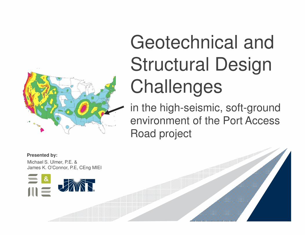
Geotechnical and Structural Design Challenges in the high-seismic, soft-ground environment of the Port Access Road project
Michael S. Ulmer, P.E. &James K. O’Connor, P.E, CEng MIEI
Presented by:
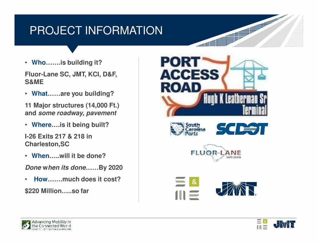
• Who…….is building it?
Fluor-Lane SC, JMT, KCI, D&F, S&ME
• What……are you building?
11 Major structures (14,000 Ft.) and some roadway, pavement
• Where….is it being built?
I-26 Exits 217 & 218 in Charleston,SC
• When…..will it be done?
Done when its done……By 2020
• How…….much does it cost?
$220 Million…..so far
PROJECT INFORMATION
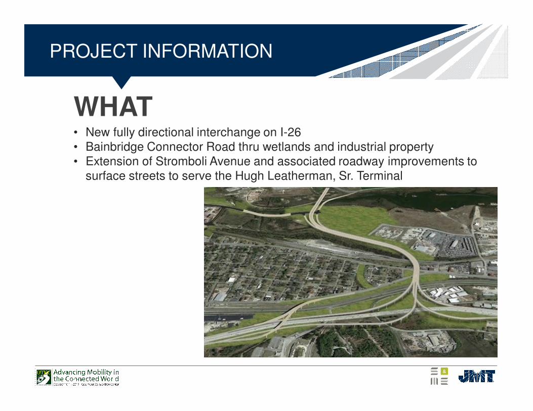
WHAT
PROJECT INFORMATION
• New fully directional interchange on I-26• Bainbridge Connector Road thru wetlands and industrial property• Extension of Stromboli Avenue and associated roadway improvements to
surface streets to serve the Hugh Leatherman, Sr. Terminal
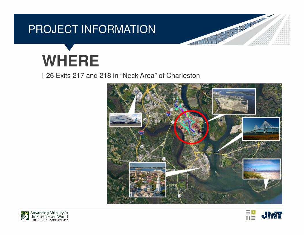
WHERE
PROJECT INFORMATION
I-26 Exits 217 and 218 in “Neck Area” of Charleston
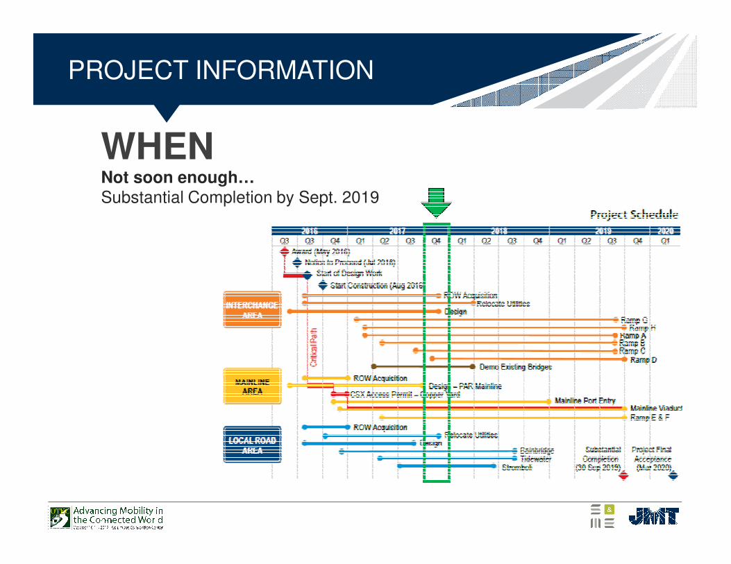
WHEN
PROJECT INFORMATION
Not soon enough…Substantial Completion by Sept. 2019
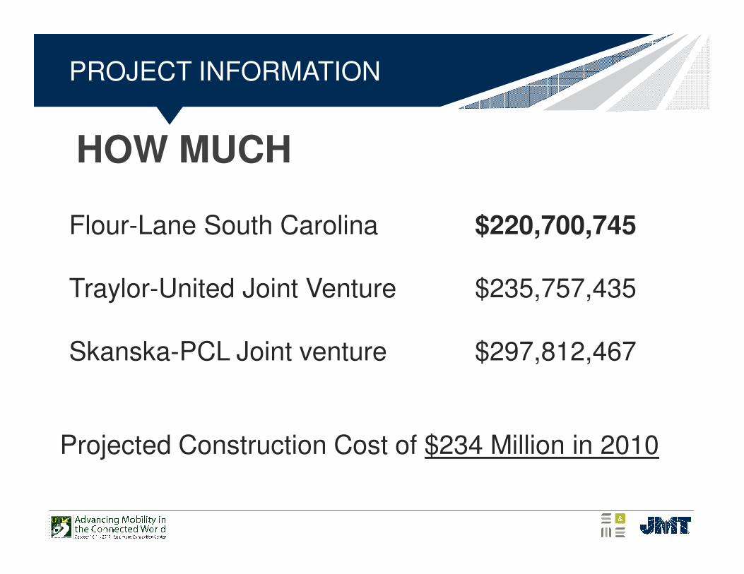
HOW MUCH
PROJECT INFORMATION
Flour-Lane South Carolina $220,700,745
Traylor-United Joint Venture $235,757,435
Skanska-PCL Joint venture $297,812,467
Projected Construction Cost of $234 Million in 2010
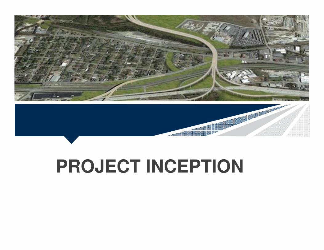
PROJECT INCEPTION
STEP 1 2005-2006
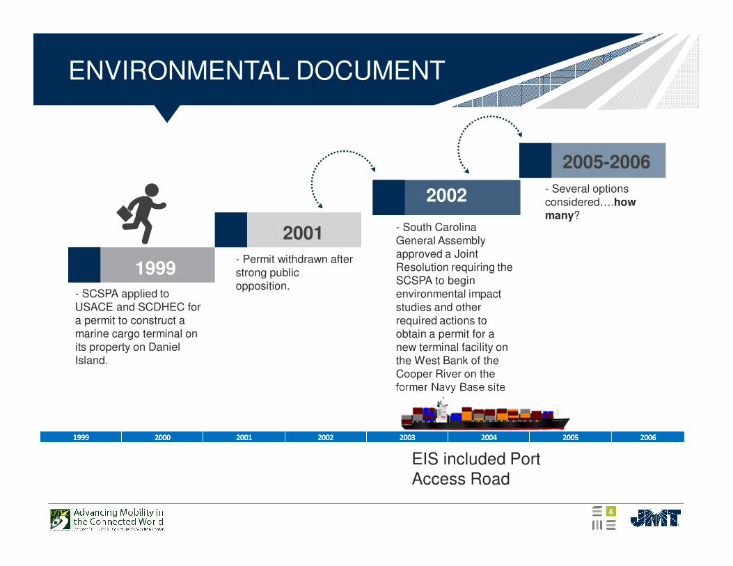
- Permit withdrawn after strong public opposition..
- South Carolina General Assembly approved a Joint Resolution requiring the SCSPA to begin environmental impact studies and other required actions to obtain a permit for a new terminal facility on the West Bank of the Cooper River on the former Navy Base site.
- Several options considered….how many?
2002
2001
1999
ENVIRONMENTAL DOCUMENT
- SCSPA applied to USACE and SCDHEC for a permit to construct a marine cargo terminal on its property on Daniel Island.
EIS included Port Access Road
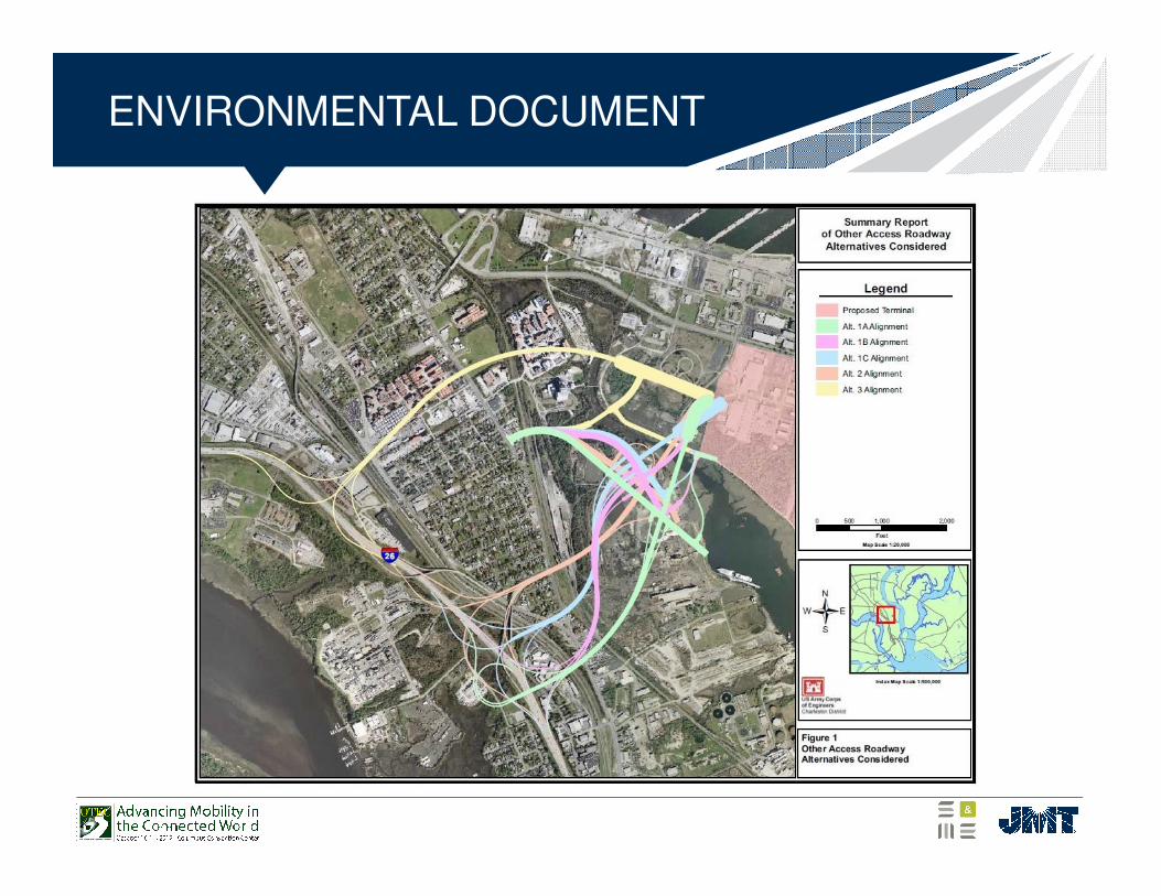
ENVIRONMENTAL DOCUMENT
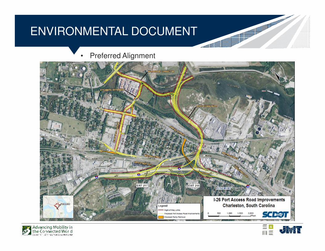
• Preferred Alignment
ENVIRONMENTAL DOCUMENT
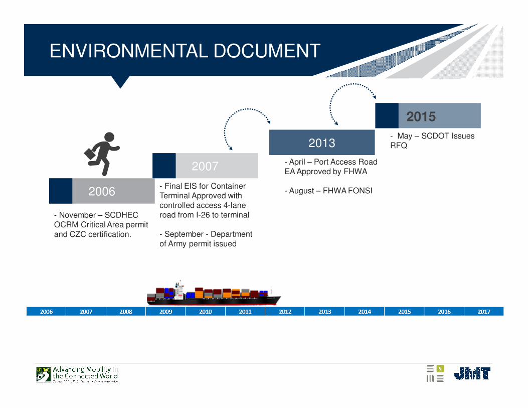
ENVIRONMENTAL DOCUMENT
2006
2007
2013
2015
- November – SCDHECOCRM Critical Area permit and CZC certification.
- Final EIS for Container Terminal Approved with controlled access 4-lane road from I-26 to terminal
- September - Department of Army permit issued
- April – Port Access Road EA Approved by FHWA
- August – FHWA FONSI
- May – SCDOT Issues RFQ
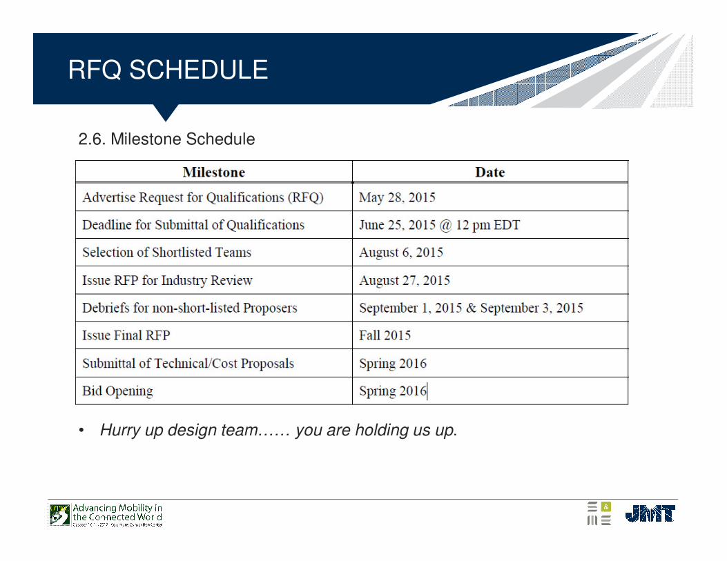
RFQ SCHEDULE
2.6. Milestone Schedule
• Hurry up design team…… you are holding us up.
DESIGN CHALLENGES
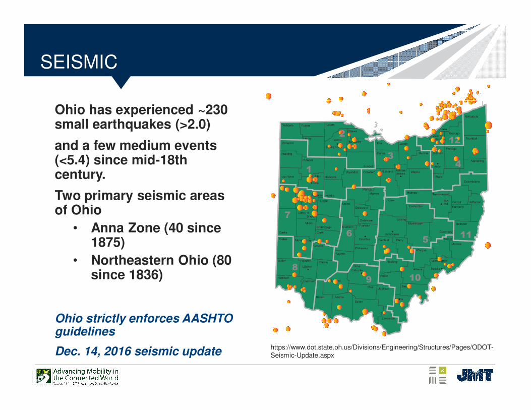
SEISMIC
Ohio has experienced ~230 small earthquakes (>2.0)
and a few medium events (<5.4) since mid-18th century.
Two primary seismic areas of Ohio
• Anna Zone (40 since 1875)
• Northeastern Ohio (80 since 1836)
Ohio strictly enforces AASHTO guidelines
Dec. 14, 2016 seismic update https://www.dot.state.oh.us/Divisions/Engineering/Structures/Pages/ODOT-Seismic-Update.aspx
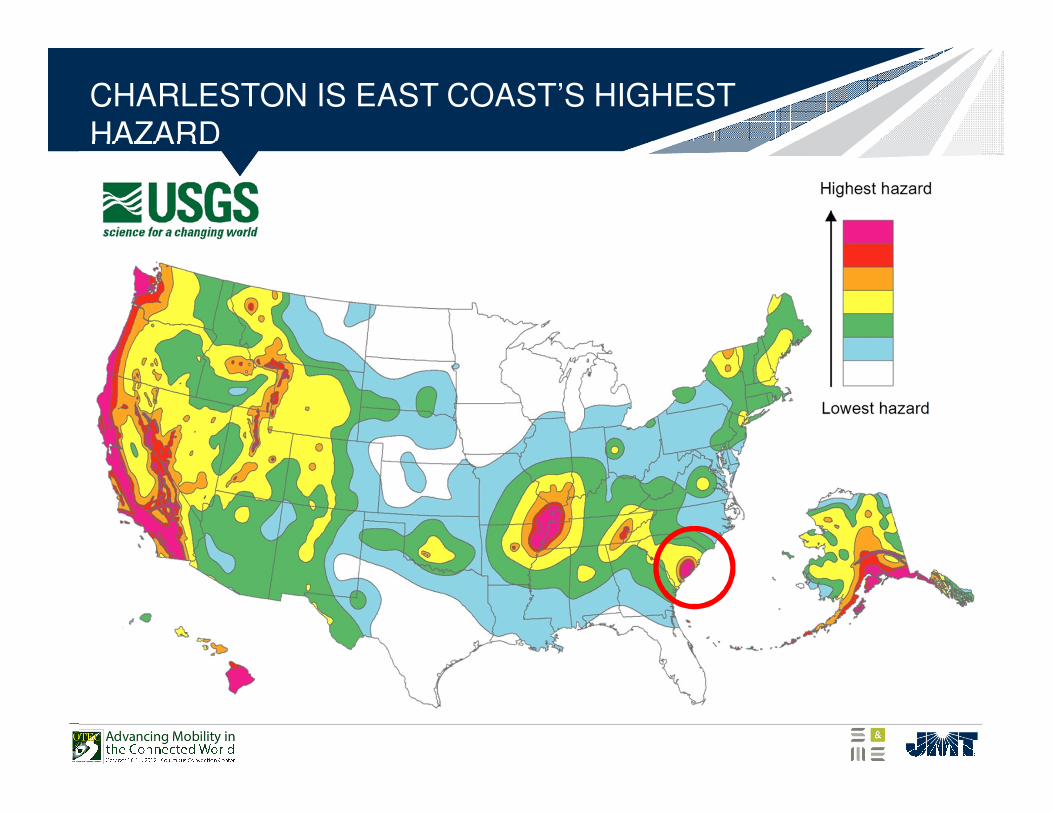
CHARLESTON IS EAST COAST’S HIGHEST HAZARD
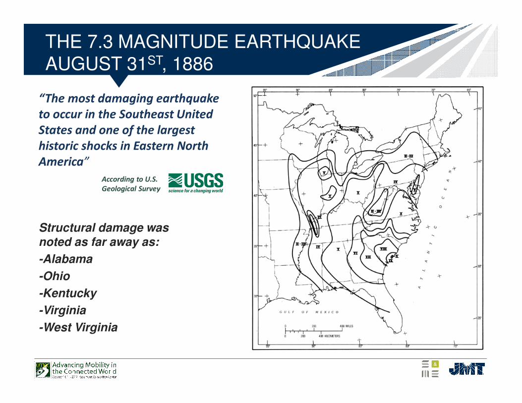
THE 7.3 MAGNITUDE EARTHQUAKE AUGUST 31ST, 1886
Structural damage was
noted as far away as:
-Alabama
-Ohio
-Kentucky
-Virginia
-West Virginia
According to U.S.
Geological Survey
“The most damaging earthquake
to occur in the Southeast United
States and one of the largest
historic shocks in Eastern North
America”
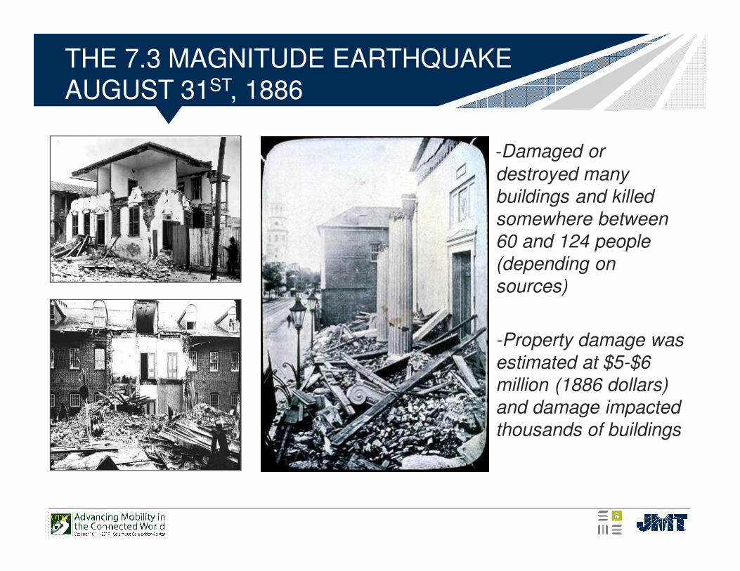
THE 7.3 MAGNITUDE EARTHQUAKE AUGUST 31ST, 1886
-Damaged or destroyed many buildings and killed somewhere between 60 and 124 people (depending on sources)
-Property damage was estimated at $5-$6 million (1886 dollars) and damage impacted thousands of buildings
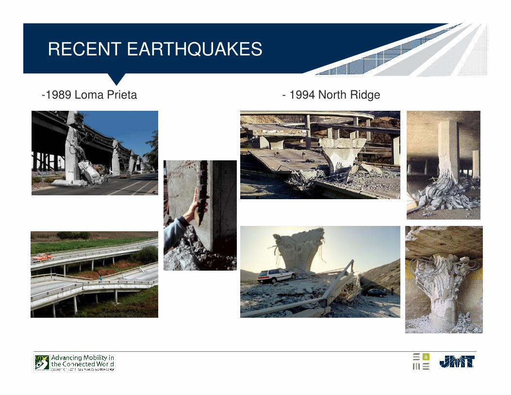
RECENT EARTHQUAKES
-1989 Loma Prieta - 1994 North Ridge
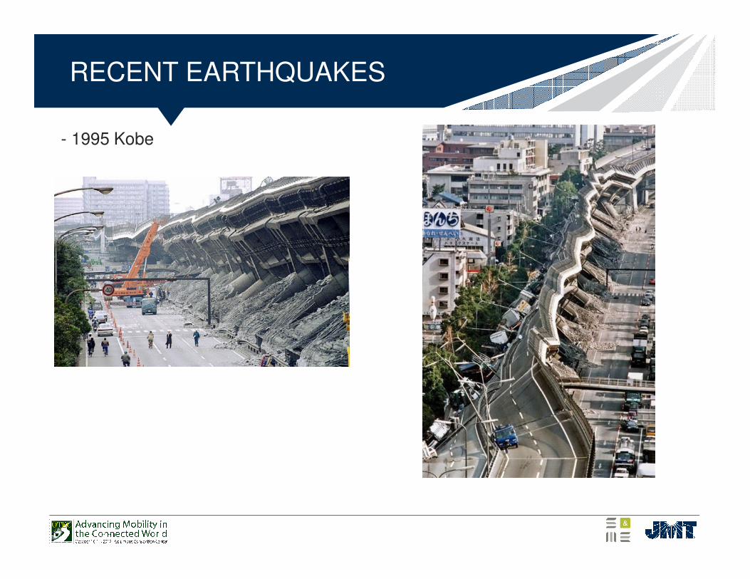
RECENT EARTHQUAKES
- 1995 Kobe
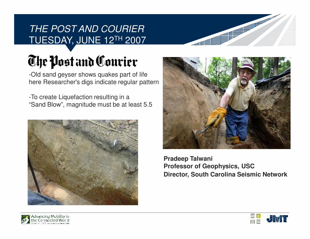
THE POST AND COURIER TUESDAY, JUNE 12TH 2007
-Old sand geyser shows quakes part of life here Researcher's digs indicate regular pattern
-To create Liquefaction resulting in a “Sand Blow”, magnitude must be at least 5.5
Pradeep TalwaniProfessor of Geophysics, USC
Director, South Carolina Seismic Network
GDM
• South Carolina Department of Transportation’s Geotechnical Design Manual (GDM)
• “learn it, love it, live it…”
• GDM dictates practically everything about the project’s subsurface exploration and geotechnical engineering.
• A comprehensive resource for geotechnical explorations; soil parameters (strength and compressibility); and geotechnical engineering processes, methods, and techniques.
• A strict performance specification, which make design “challenging” in soft-ground and high-seismic sites.
• New version to be released later this year addresses some of the unreasonable performance specifications.

GDM
GEOTECHNICAL INVESTIGATION
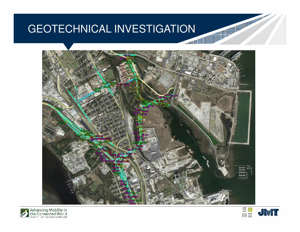
• 260 Test Locations (to date)• 58 “borings” from the Base Line Report• >200 “borings” during design-build phase• Roughly half are CPT/DMT soundings• Roughly half are soil test borings• A “boring” at every bent, two at each abutment, and more along the
roadways, walls, signs, etc.• In situ testing included vane shear, shear wave velocity (MASW and
SCPT), and DMT• Lots or coordination with Contractor for site access
• Permission to access private property• Salt marsh areas, un-level areas• Wooded areas needed clearing• Traffic control (lots of traffic control)
• Significant lab testing program• Field Exploration has been completed on time and on budget
GEOTECHNICAL INVESTIGATION
HAZMAT INVESTIGATION
• Project is in the historic industrial “Neck Area” of Charleston• Numerous parcels are contaminated• SCDOT spent significant resources to study the project corridor and
identify the parcels of concern and how those concerns would affect design and construction.
• Lots of scientists, engineers, and lawyers involved• The Big ones:
• Solvay, Navy Base, and Macalloy• Five other parcels with Voluntary Cleanup Contracts• Numerous other parcels with concerns, some to be found
• All drilled shaft and shallow excavations located on contaminated parcels require HAZMAT sampling and testing
• Data collected is used to characterize the spoils for disposal• This has been a significant effort, and has been completed on time and
on budget.
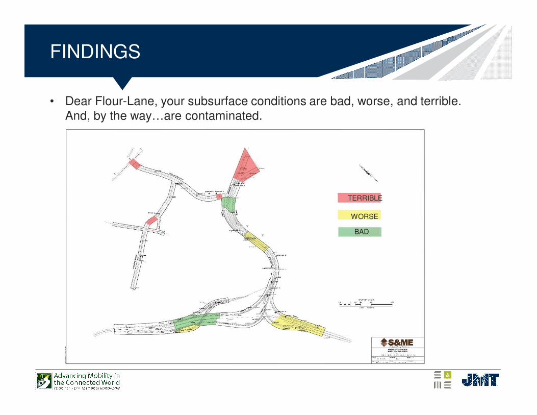
FINDINGS
• Dear Flour-Lane, your subsurface conditions are bad, worse, and terrible. And, by the way…are contaminated.
TERRIBLE
WORSE
BAD
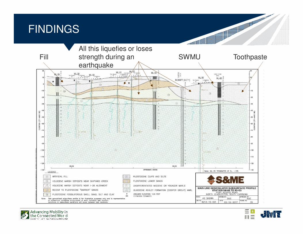
FINDINGS
FillAll this liquefies or loses strength during an earthquake
SWMU Toothpaste
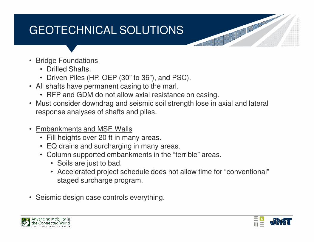
GEOTECHNICAL SOLUTIONS
• Bridge Foundations• Drilled Shafts.• Driven Piles (HP, OEP (30” to 36”), and PSC).
• All shafts have permanent casing to the marl.• RFP and GDM do not allow axial resistance on casing.
• Must consider downdrag and seismic soil strength lose in axial and lateral response analyses of shafts and piles.
• Embankments and MSE Walls• Fill heights over 20 ft in many areas.• EQ drains and surcharging in many areas.• Column supported embankments in the “terrible” areas.
• Soils are just to bad.• Accelerated project schedule does not allow time for “conventional”
staged surcharge program.
• Seismic design case controls everything.
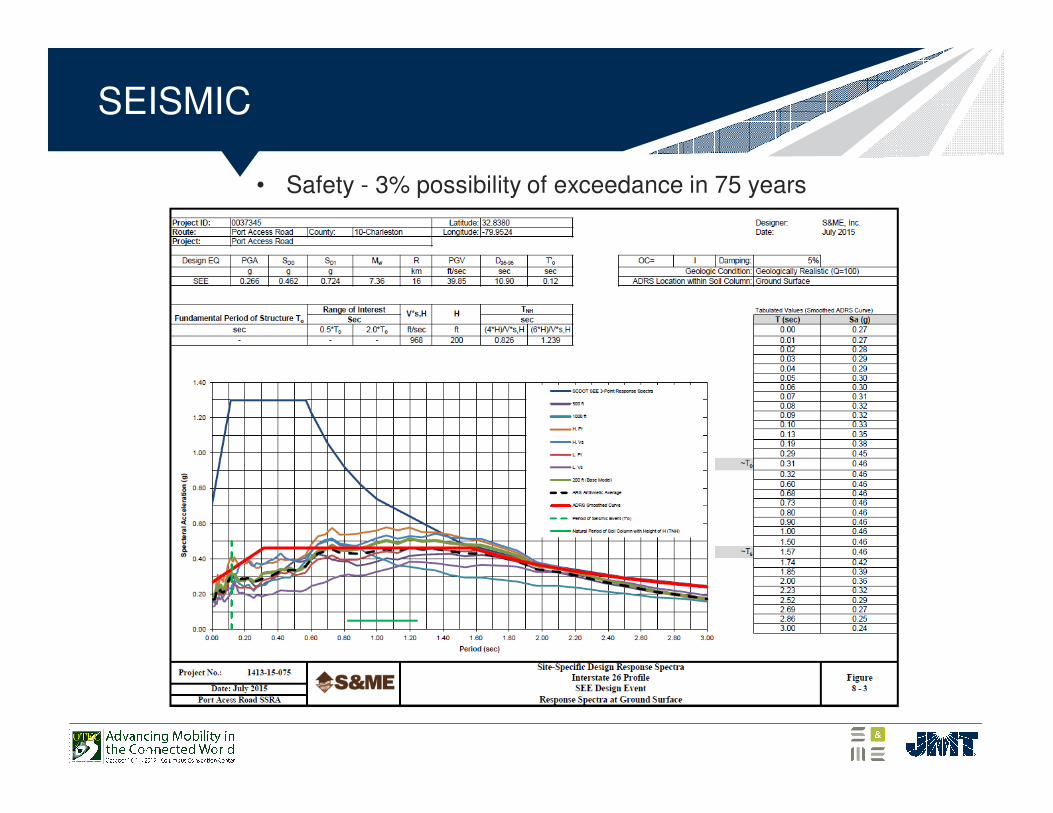
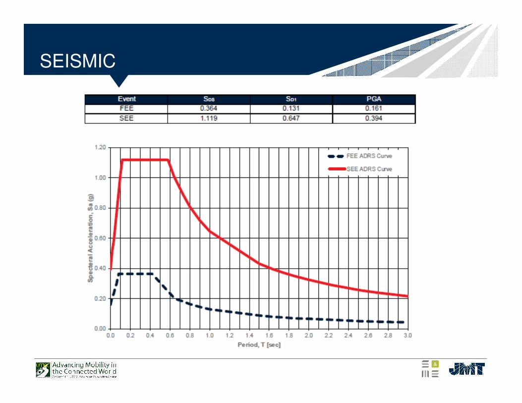
SEISMIC
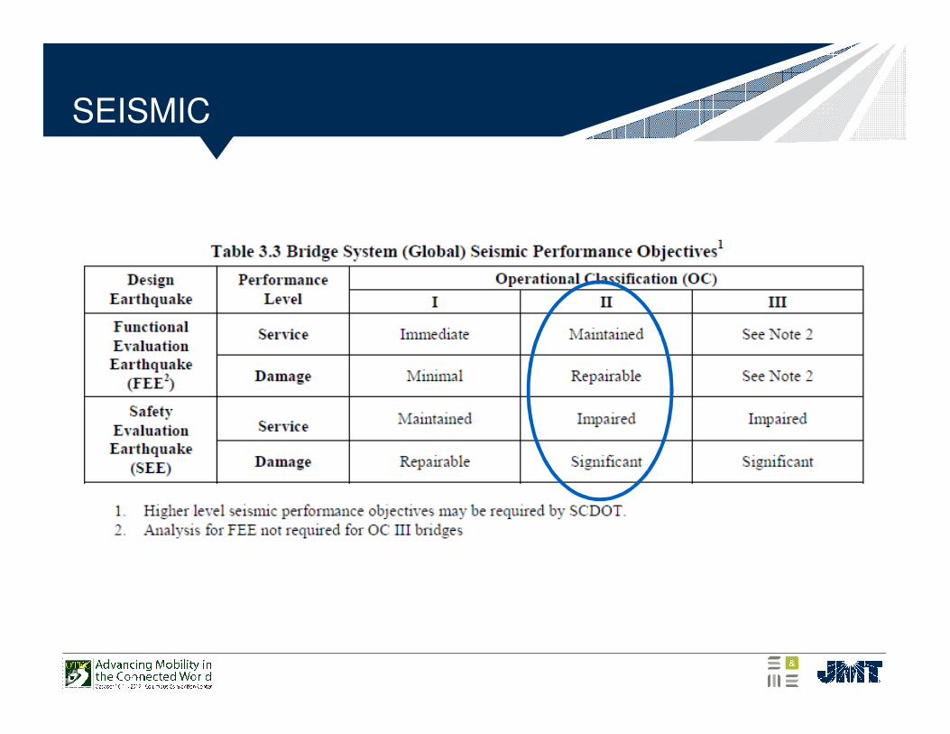
• Safety - 3% possibility of exceedance in 75 years
SEISMIC
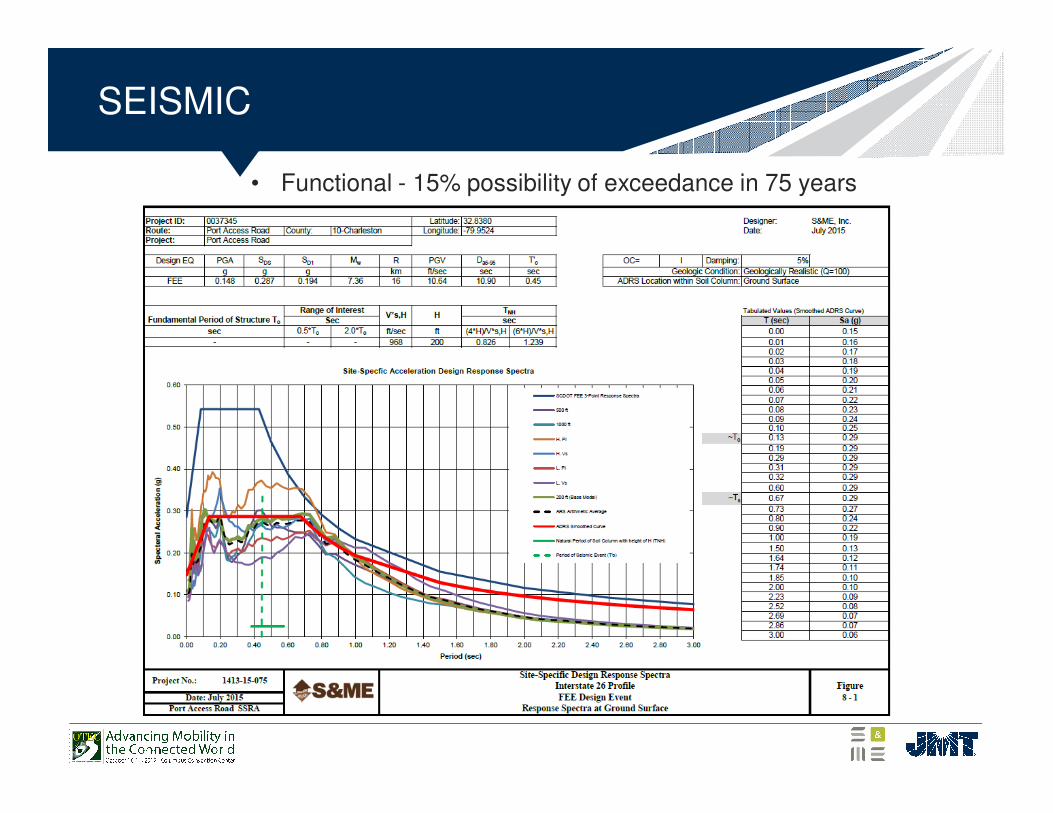
• Functional - 15% possibility of exceedance in 75 years
DESIGN SOLUTIONS
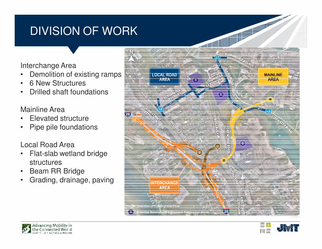
DIVISION OF WORK
Interchange Area• Demolition of existing ramps• 6 New Structures• Drilled shaft foundations
Mainline Area • Elevated structure• Pipe pile foundations
Local Road Area• Flat-slab wetland bridge
structures• Beam RR Bridge• Grading, drainage, paving

TYPICAL I-26 INTERCHANGE STRUCTURES
• All have one 16ft. Lane with 10’ and 6’ shoulders.
I-26 INTERCHANGE STRUCTURES
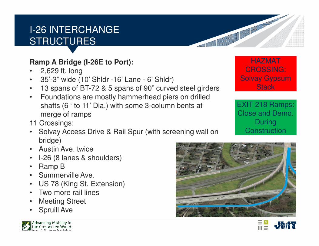
Ramp A Bridge (I-26E to Port):• 2,629 ft. long• 35’-3” wide (10’ Shldr -16’ Lane - 6’ Shldr)• 13 spans of BT-72 & 5 spans of 90” curved steel girders• Foundations are mostly hammerhead piers on drilled
shafts (6 ‘ to 11’ Dia.) with some 3-column bents at merge of ramps
11 Crossings:• Solvay Access Drive & Rail Spur (with screening wall on
bridge)• Austin Ave. twice• I-26 (8 lanes & shoulders)• Ramp B• Summerville Ave.• US 78 (King St. Extension)• Two more rail lines• Meeting Street• Spruill Ave
HAZMAT CROSSING:
Solvay Gypsum Stack
EXIT 218 Ramps:Close and Demo.
During Construction
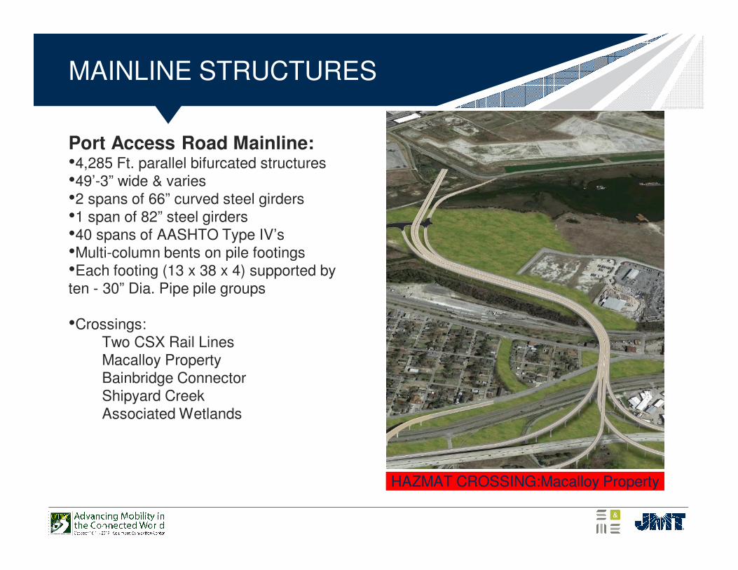
MAINLINE STRUCTURES
Port Access Road Mainline:•4,285 Ft. parallel bifurcated structures•49’-3” wide & varies•2 spans of 66” curved steel girders•1 span of 82” steel girders•40 spans of AASHTO Type IV’s•Multi-column bents on pile footings•Each footing (13 x 38 x 4) supported by ten - 30” Dia. Pipe pile groups
•Crossings:Two CSX Rail LinesMacalloy PropertyBainbridge ConnectorShipyard CreekAssociated Wetlands
HAZMAT CROSSING:Macalloy Property
US Coast Guard
Chisolm’s Mill
4800 ft. Project Length
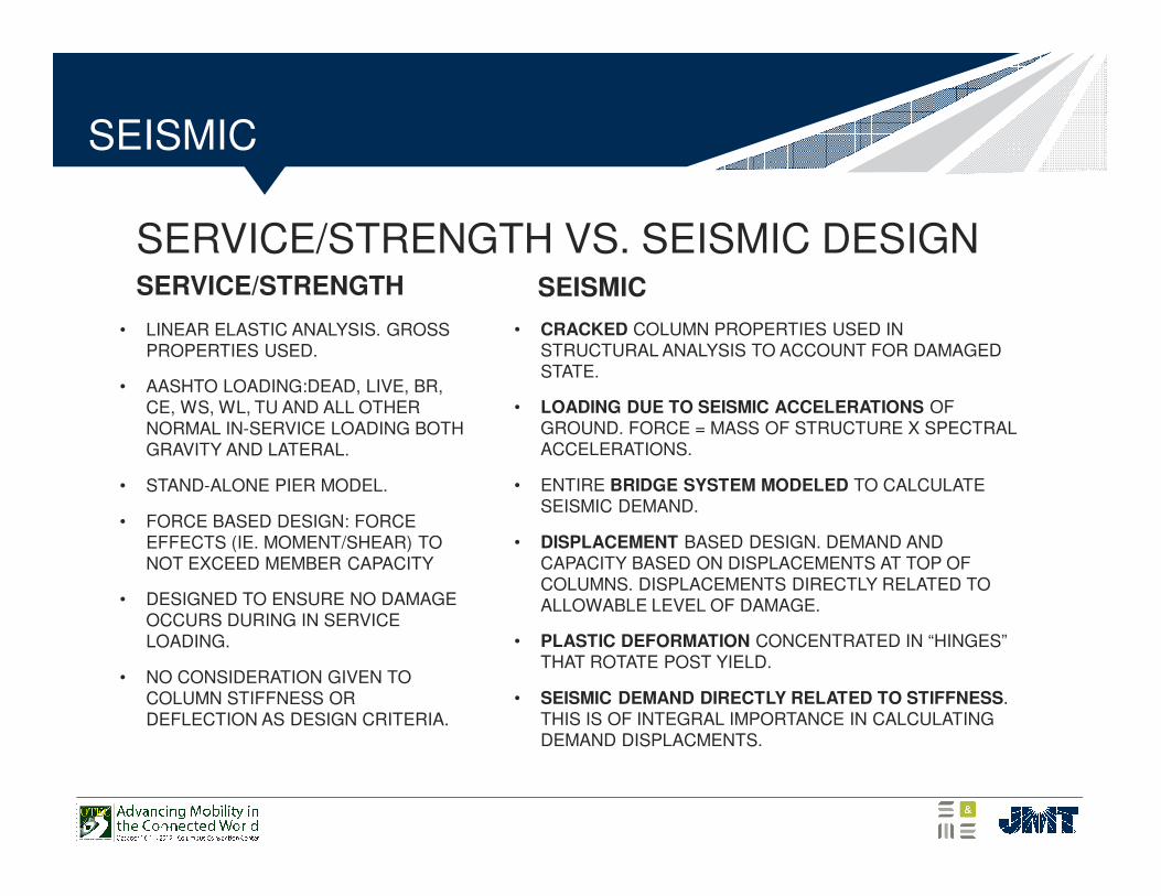
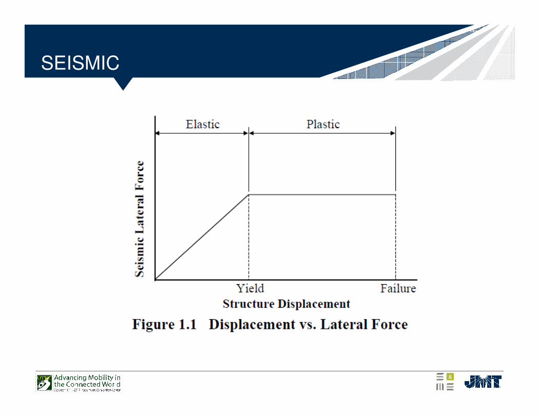
SERVICE/STRENGTH VS. SEISMIC DESIGNSERVICE/STRENGTH
• LINEAR ELASTIC ANALYSIS. GROSS PROPERTIES USED.
• AASHTO LOADING:DEAD, LIVE, BR, CE, WS, WL, TU AND ALL OTHER NORMAL IN-SERVICE LOADING BOTH GRAVITY AND LATERAL.
• STAND-ALONE PIER MODEL.
• FORCE BASED DESIGN: FORCE EFFECTS (IE. MOMENT/SHEAR) TO NOT EXCEED MEMBER CAPACITY
• DESIGNED TO ENSURE NO DAMAGE OCCURS DURING IN SERVICE LOADING.
• NO CONSIDERATION GIVEN TO COLUMN STIFFNESS OR DEFLECTION AS DESIGN CRITERIA.
SEISMIC
• CRACKED COLUMN PROPERTIES USED IN STRUCTURAL ANALYSIS TO ACCOUNT FOR DAMAGED STATE.
• LOADING DUE TO SEISMIC ACCELERATIONS OF GROUND. FORCE = MASS OF STRUCTURE X SPECTRAL ACCELERATIONS.
• ENTIRE BRIDGE SYSTEM MODELED TO CALCULATE SEISMIC DEMAND.
• DISPLACEMENT BASED DESIGN. DEMAND AND CAPACITY BASED ON DISPLACEMENTS AT TOP OF COLUMNS. DISPLACEMENTS DIRECTLY RELATED TO ALLOWABLE LEVEL OF DAMAGE.
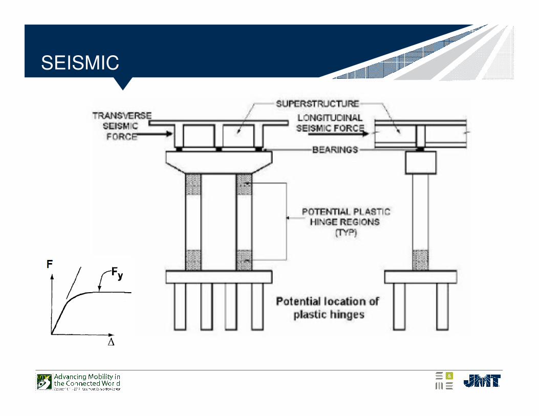
• PLASTIC DEFORMATION CONCENTRATED IN “HINGES” THAT ROTATE POST YIELD.
• SEISMIC DEMAND DIRECTLY RELATED TO STIFFNESS. THIS IS OF INTEGRAL IMPORTANCE IN CALCULATING DEMAND DISPLACMENTS.
SEISMIC
SEISMIC
SEISMIC
SEISMIC
SEISMIC
SEISMIC 3D Modeling
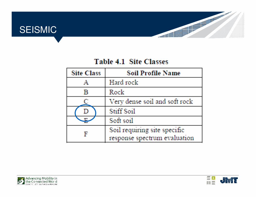
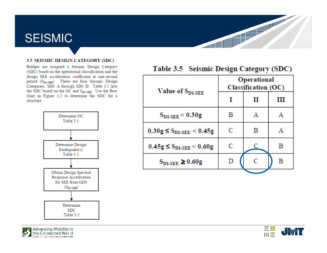
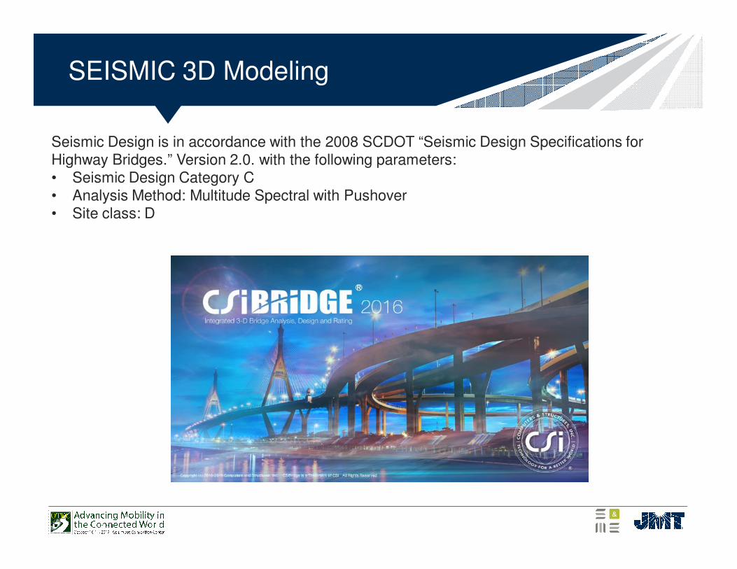
Seismic Design is in accordance with the 2008 SCDOT “Seismic Design Specifications for Highway Bridges.” Version 2.0. with the following parameters: • Seismic Design Category C• Analysis Method: Multitude Spectral with Pushover • Site class: D
SEISMIC 3D Modeling
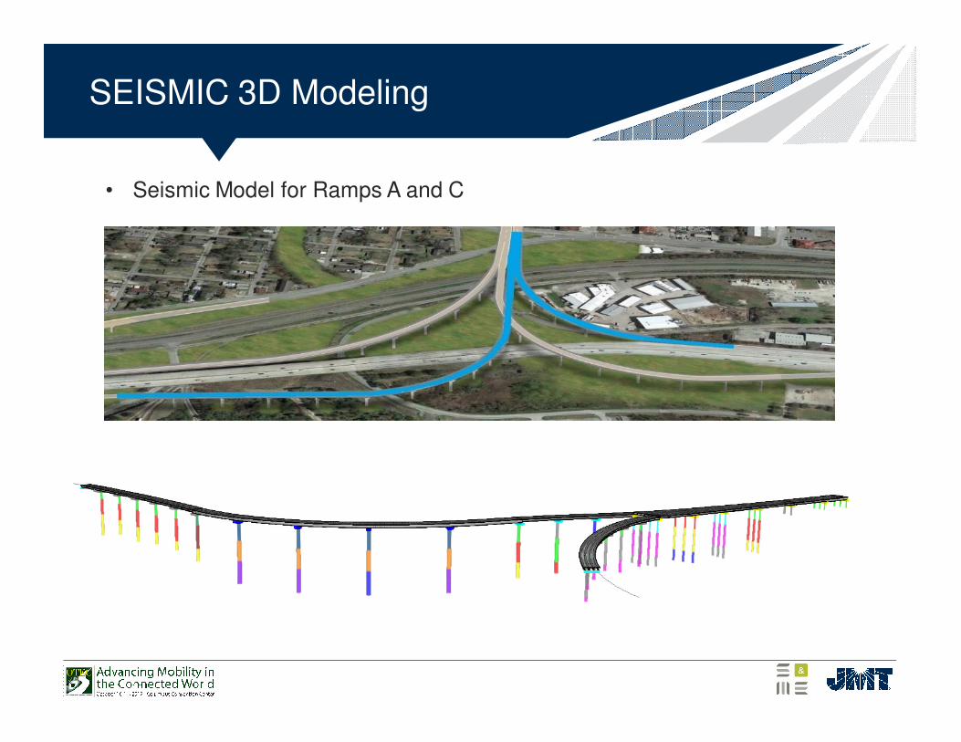
• Seismic Model for Ramps A and C
SEISMIC 3D Modeling
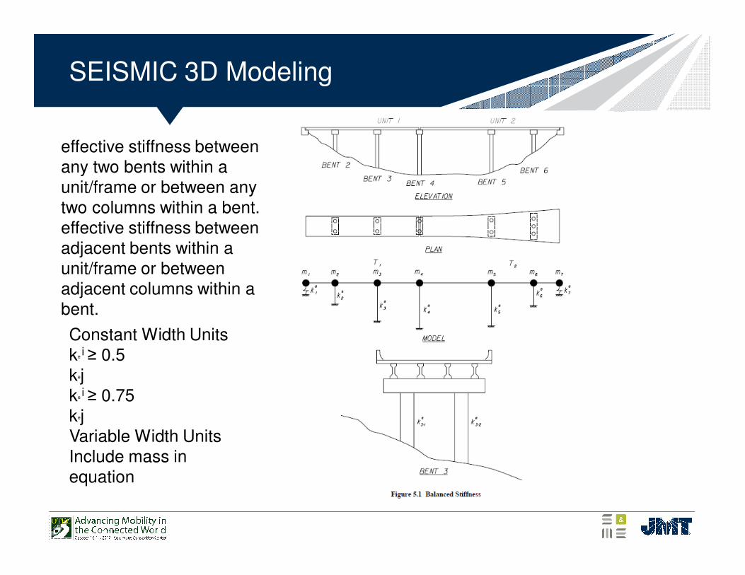
Constant Width Unitske
i ≥ 0.5kejke
i ≥ 0.75kejVariable Width UnitsInclude mass in equation
effective stiffness between any two bents within a unit/frame or between any two columns within a bent.effective stiffness between adjacent bents within a unit/frame or between adjacent columns within a bent.
SEISMIC 3D Modeling
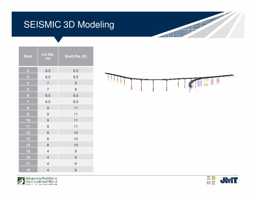
Bentcol Dia.
(ft)Shaft Dia. (ft)
2 6.5 8.5
3 6.5 8.5
4 7 9
5 7 9
6 6.5 8.5
7 6.5 8.5
8 9 11
9 9 11
10 9 11
11 9 11
12 8 10
13 8 10
14 8 10
15 4 6
16 4 6
17 4 6
18 4 6
SEISMIC 3D Modeling
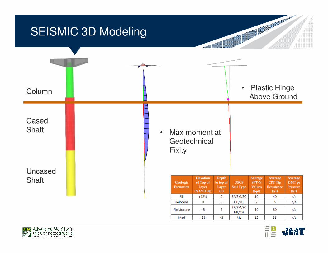
Column
Cased Shaft
Uncased Shaft
• Max moment at Geotechnical Fixity
• Plastic Hinge Above Ground
SEISMIC
SEISMIC
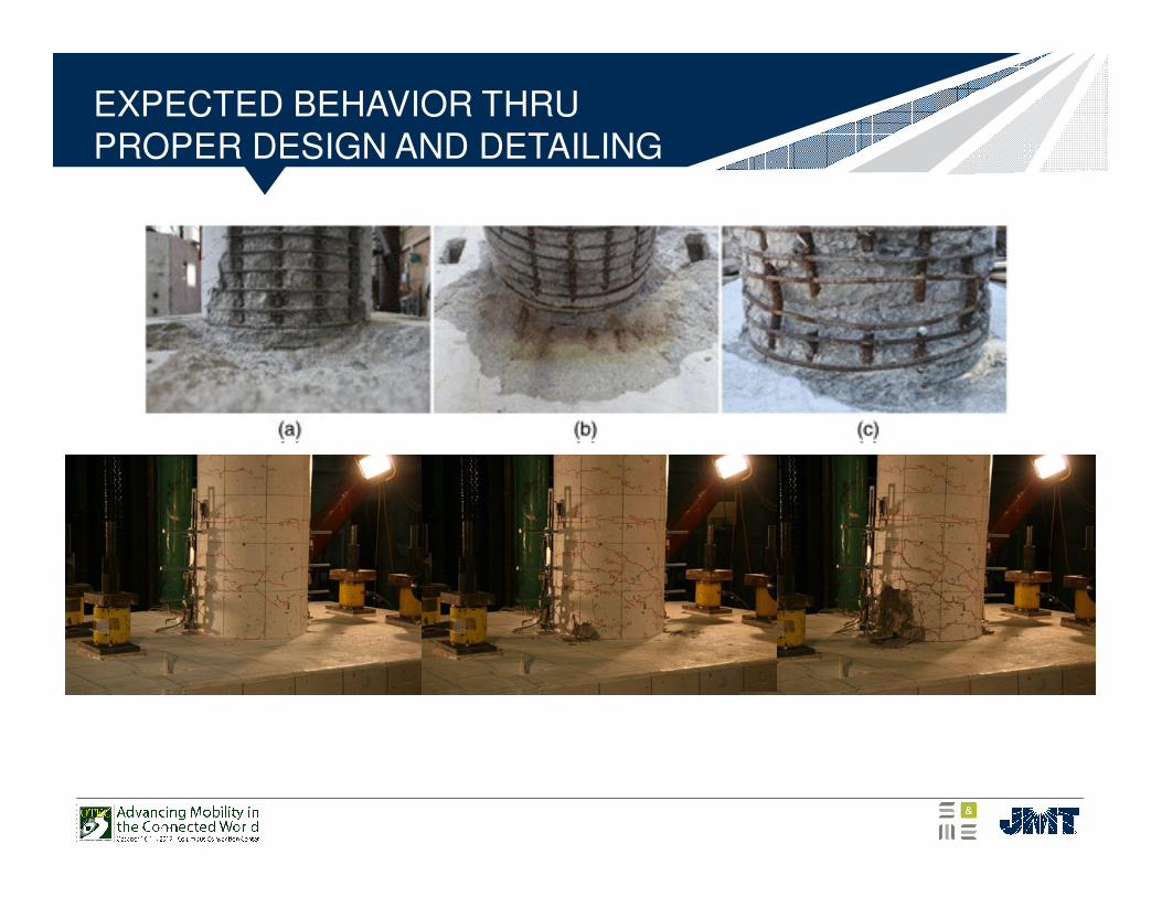
EXPECTED BEHAVIOR THRU PROPER DESIGN AND DETAILING
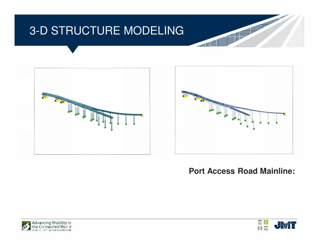
3-D STRUCTURE MODELING
Port Access Road Mainline:
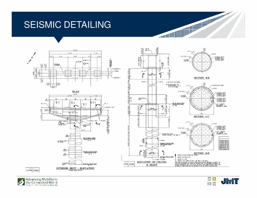
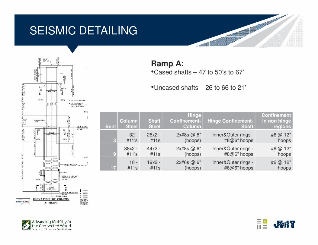
SEISMIC DETAILING
SEISMIC DETAILING
BentColumn
SteelShaft Steel
Hinge Confinement-
ColumnHinge Confinement-
Shaft
Confinement in non hinge
regions
332 -
#11's26x2 -
#11s2x#8s @ 6"
(hoops)Inner&Outer rings -
#8@6" hoops#6 @ 12"
hoops
938x2 -#11's
44x2 -#11s
2x#8s @ 6" (hoops)
Inner&Outer rings -#8@6" hoops
#6 @ 12" hoops
1718 -
#11s19x2 -
#11s2x#6s @ 6"
(hoops)Inner&Outer rings -
#6@6" hoops#6 @ 12"
hoops
Ramp A:•Cased shafts – 47 to 50’s to 67’
•Uncased shafts – 26 to 66 to 21’
FULL SCALE TEST
The 145-foot-long, 162-ton steel and concrete bridge was built atop four large, 14-foot by 14-foot, hydraulic shake tables in the University of Nevada, Reno's world-renowned Large-Scale Structures

FULL SCALE TEST OF NORTHRIDGE EQ IN UNIVERSITY OF NEVADA SHAKE LAB
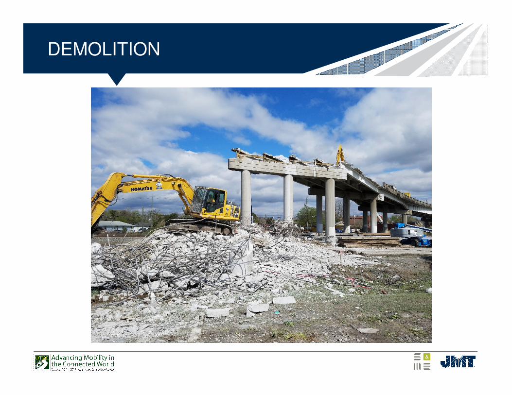
DEMOLITION
STATUS
• Demolition is complete.
• Design effort is complete
• Earthquake drains have been installed at G/H Ramps
• Drilled shaft load test is complete - Required reevaluate
of drilled shaft design
• Tip elevations did not change (steel was on the ground
being tied)
• Production shafts have started
• Pile driving has started
• PDA testing confirmed design
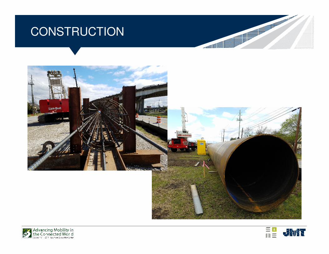
CONSTRUCTION
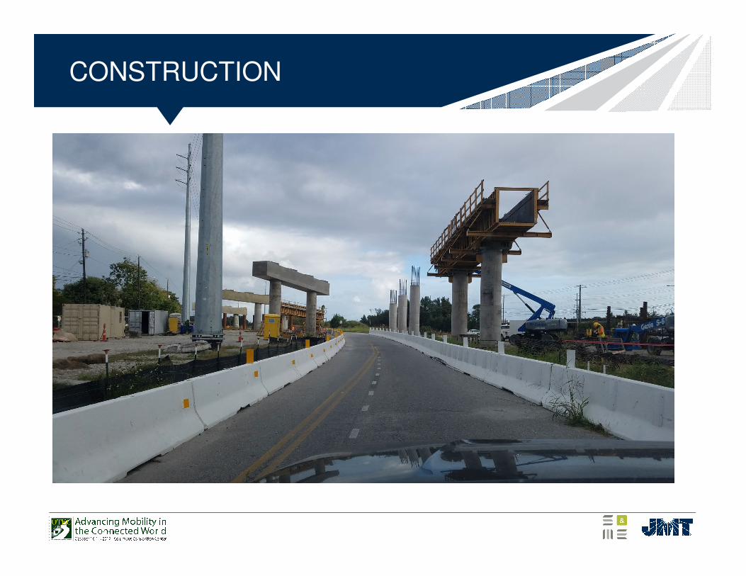
CONSTRUCTION
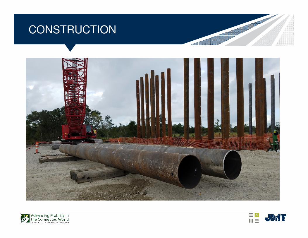
CONSTRUCTION
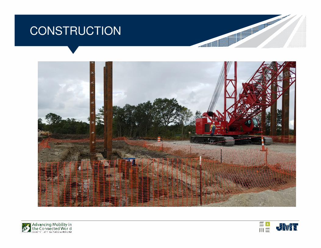
CONSTRUCTION
Questions?
Michael S. Ulmer, PE
James K. O’Connor, PE, CEng MIEI