geotechnical data report - sabal trail...
TRANSCRIPT
Geotechnical Data Report
Sabal Trail Transmission Hillabee Creek HDD Gulf Interstate Engineering
for
Gulf Interstate Engineering
November 17, 2014

Geotechnical Data Report
Sabal Trail Transmission
Hillabee Creek HDD
Tallapoosa County, Alabama
for
Gulf Interstate Engineering
November 17, 2014
3050 South Delaware Avenue
Springfield, Missouri 65804
417.831.9700
Geotechnical Data Report
Sabal Trail Transmission
Hillabee Creek HDD
Tallapoosa County, Alabama
File No. 15347-006-00
November 17, 2014
Prepared for:
Gulf Interstate Engineering
16010 Barkers Point Lane, Suite 600
Houston, Texas 77079-9000
Attention: Denys Stavnychyi, Project Engineer
Prepared by:
GeoEngineers, Inc.
3050 South Delaware Avenue
Springfield, Missouri 65804
417.831.9700
Mark A. Miller, PE
Principal
David P. Sauls, PE
Senior Principal
NAA:MAM:DPS:kb
Disclaimer: Any electronic form, facsimile or hard copy of the original document (email, text, table, and/or figure), if provided, and any attachments are only a
copy of the original document. The original document is stored by GeoEngineers, Inc. and will serve as the official document of record.
Copyright© 2014 by GeoEngineers, Inc. All rights reserved.

November 17, 2014| Page i File No. 15347-006-00
Table of Contents
1.0 INTRODUCTION ................................................................................................................................. 1
2.0 SCOPE .................................................................................................................................................. 1
3.0 SITE CONDITIONS ................................................................................................................................ 2
3.1 Geological Conditions ..................................................................................................................... 2
3.1.1 Regional Geologic Setting ..................................................................................................... 2
3.1.2 Site Geology ........................................................................................................................... 3
3.2 Subsurface Conditions .................................................................................................................... 3
3.2.1 General .................................................................................................................................. 3
3.2.2 Subsurface Description ........................................................................................................ 3
3.2.3 Cerchar Abrasivity Testing .................................................................................................... 4
3.2.4 Groundwater Conditions ....................................................................................................... 5
3.3 Surface Conditions .......................................................................................................................... 6
3.3.1 General .................................................................................................................................. 6
3.3.2 Surface Description .............................................................................................................. 6
4.0 LIMITATIONS ........................................................................................................................................ 6
5.0 REFERENCES ....................................................................................................................................... 7
LIST OF FIGURES
Figure 1. Vicinity Map
Figure 2. Site Plan and Profile
Figure 3. Geologic Map
Figures 4 and 5. Site Photographs
APPENDICES
Appendix A. Field Explorations and Laboratory Testing
Figure A-1 – Key to Exploration Logs
Figure A-2 – URCS Rock Classification
Figures A-3 through A-6 – Logs of Borings
Figures A-7 and A-8 – Atterberg Limits Test Results
Figure A-9 - Sieve Analysis Results
Figures A-10 through A-13 – Rock Core Test Results
Figures A-14 through A-42 – Rock Core Photographs
Cerchar Abrasivity Test Report
Appendix B. Report Limitations and Guidelines for Use

November 17, 2014| Page 1 File No. 15347-006-00
1.0 INTRODUCTION
GeoEngineers, Inc. (GeoEngineers) is pleased to submit this geotechnical data report for the proposed
Sabal Trail Transmission Project (Sabal Trail) Hillabee Creek Horizontal Directional Drill (HDD) at
approximate milepost (MP) 1.35 located in Tallapoosa County, Alabama. The location of the site is shown
on the Vicinity Map, Figure 1.
The proposed project consists of a new 36-inch-diameter steel pipeline to be installed using the HDD
method of construction as part of a new approximately 475-mile long interstate natural gas pipeline
project. The design horizontal length of the proposed Hillabee Creek HDD is 2,715 feet, crossing beneath
Hillabee Creek. The general layout of the site is shown in the Site Plan and Profile, Figure 2.
We explored subsurface conditions near the proposed HDD site by drilling four geotechnical borings (HC-
B-1 through HC-B-4) to depths up to 245 feet below ground surface (bgs) adjacent to the alignment of the
proposed HDD. In general, the subsurface conditions encountered in the borings were consistent with
published geology for the area. Details of our subsurface exploration program are included in Section 3.2
and the exploration logs are included in Appendix A.
2.0 SCOPE
The purpose of our services was to evaluate the existing surface and subsurface soil and groundwater
conditions and to prepare a geotechnical data report. The specific scope of services provided by
GeoEngineers included the following:
Task 1 – Conceptual HDD Plan and Profile Drawings
1. Reviewed available project information provided by Gulf Interstate Engineering (GIE) and publicly
available geologic maps, subsurface information, ground surface elevation data, aerial photographs
and other documentation for the project area.
2. Prepared a conceptual HDD alignment and profile drawing with proposed boring locations based on
topographic data from publicly available sources.
Task 2 – Site Reconnaissance
1. Performed an engineer site visit to the proposed crossing to observe site access, surface conditions,
and potential HDD constructability issues.
Task 3 – Geotechnical Exploration and Laboratory Testing
1. Contacted the applicable “One Call” agency to notify them of our intent to perform soil borings at the
site and to clear the boring locations of potential underground utilities.
2. Explored subsurface conditions at the site by completing a total of four (4) geotechnical borings to
depths between 115 and 245 feet bgs using a hollow-stem auger and NQ-sized rock coring
equipment. The explorations were completed using a track-mounted drilling rig.
3. Backfilled the borings full-depth with cement-bentonite grout upon completion.
4. Completed a laboratory testing program on selected samples obtained from the borings to evaluate
pertinent engineering properties. The tests included the following:

November 17, 2014| Page 2 File No. 15347-006-00
■ Standard classification of soils in general accordance with ASTM International (ASTM) D2488.
■ Gradation of soils in general accordance with ASTM D422.
■ Moisture content determination in general accordance with ASTM D2216.
■ Atterberg limits determination in general accordance with ASTM D4318.
■ Unconfined compressive strength of rock core samples in general accordance with ASTM D7012.
■ Cerchar Abrasivity Index (CAI) tests (performed by the Earth Mechanics Institute at the Colorado School of Mines) Cerchar (2001).
5. Prepared logs of the borings including the following:
■ Standard Penetration Test (SPT) values for soils.
■ Rock Quality Designation (RQD) and recovery values for rock core samples.
■ Shear strength properties as applicable.
■ Index and classification properties of soil and rock.
6. Evaluated the potential for geohazards at the proposed crossing site based on the subsurface information gathered from the subsurface explorations.
3.0 SITE CONDITIONS
3.1 Geological Conditions
3.1.1 Regional Geologic Setting
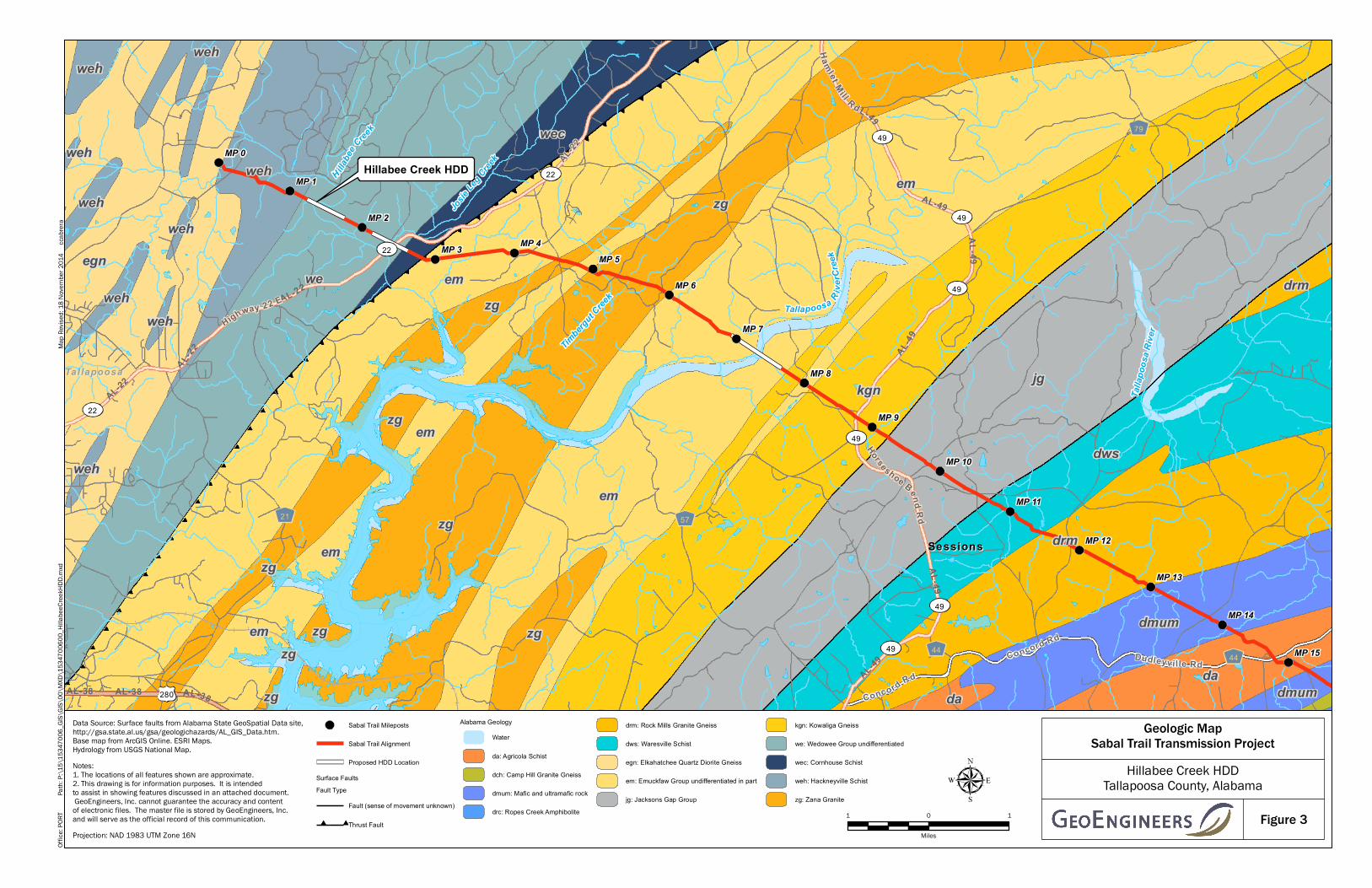
The proposed Sabal Trail alignment from MP 0.0 to approximately MP 7.5 is located in the Tallapoosa Block of the Northern Piedmont lithotectonic section of the Piedmont physiographic province. The Northern Piedmont is faulted against the Appalachian fold and thrust belt on the northwest along the Talladega-Cartersville fault system. The Tallapoosa Block contains two distinctly different metasedimentary sequences: the Wedowee Group and the Emuckfaw Group (Figure 3). The Wedowee Group forms the most areally extensive unit in the Northern Piedmont. The internal metamorphic stratigraphy of the Wedowee is complex as a result of a diverse original sedimentary rock assemblage and the different metamorphic and tectonic facies superimposed on them. The Emuckfaw Group on the southeast side of the Tallapoosa block is an interlayered sequence of muscovite-biotite schist, metagraywacke, and locally quartzite and amphibolite. In the eastern part of the outcrop belt, there is a zone of graphitic aluminous schist that forms the core of a southwest-plunging antiform. Scattered throughout the Tallapoosa block are small bodies of metamorphosed ultramafic and mafic rock (pyroxenite and gabbro). Typically, the mineral assemblages of the Wedowee, Cornhouse and Emuckfaw rocks are in the middle to upper amphibolite facies of regional metamorphism; scattered areas contain retrograded rock in which the mineral assemblages are in the upper greenschist and lower amphibolite facies. The Tallapoosa block also contains many granitoid plutons that range in composition from granite to quartz diorite. Intruded in the Emuckfaw Group are a series of narrow elongate sills of granitic rock (Zana Granite). The relationship of these sills to the Emuckfaw is uncertain and the contacts between granitoid rocks and the metasedimentary rock sequences are obscure. (Raymond, D.E., et. al., 1988)
November 17, 2014| Page 3 File No. 15347-006-00
3.1.2 Site Geology
Geologic mapping indicates that the Precambrian to Paleozoic Age (4.5 billion to 250 million years ago)
Wedowee Group (undifferentiated) will be encountered at the Hillabee Creek HDD Site. The Wedowee
Group (undifferentiated) includes the Cragford Phyllite and Cutnose Gneiss geologic units. Cragford
Phyllite consists of interbedded fine-grained schist and phyllite. Locally, feldspathic biotite gneiss, calc-
silicate rock, and quartzite may also be found within the Cragford Phyllite. Cutnose Gneiss consists of
cyclically interbedded fine-grained gneiss and schist, locally with thin interbeds of phyllite and quartzite
(Szabo, et. al., 1988), (USGS Mineral Resources).
3.2 Subsurface Conditions
3.2.1 General
Subsurface conditions were explored at the site from May 12 through May 21, 2014; June 3 through June
5, 2014; and July 9 through July 15, 2014, by drilling four (4) geotechnical borings (HC-B-1 through HC-B-
4) with a track-mounted drill rig. Borings HC-B-1, HC-B-2, HC-B-3, and HC-B-4 were drilled to depths of
115 feet bgs, 180 feet bgs, 245 feet bgs, and 160 feet bgs, respectively. The borings were drilled near
the alignment of the proposed HDD in order to characterize the subsurface conditions for HDD design.
Soil samples were generally obtained from the borings at 5-foot depth intervals using 1.5-inch inside-
diameter SPT samplers. Rock core samples were generally continuously cored using NQ-sized rock coring
equipment. An engineer from GeoEngineers managed the geotechnical explorations and a technician or
staff engineer logged the borings on a full-time basis. The GeoEngineers field staff visually classified and
collected the soil and rock samples and documented other pertinent drilling information. Laboratory
tests, including moisture content determination, sieve analyses, Atterberg limits, unconfined compressive
strength and CAI, were completed on selected samples from the borings. A description of the field
exploration and laboratory testing procedures as well as logs of the borings are presented in Appendix A.
3.2.2 Subsurface Description
In general, the subsurface conditions encountered in the borings were consistent with published geology
for the area, consisting of soft to very stiff low plasticity clay with varying sand content, very stiff to hard
low plasticity silt with varying sand content, and dense to very dense fine to coarse sand overlying schist
bedrock with mica and quartz seams.
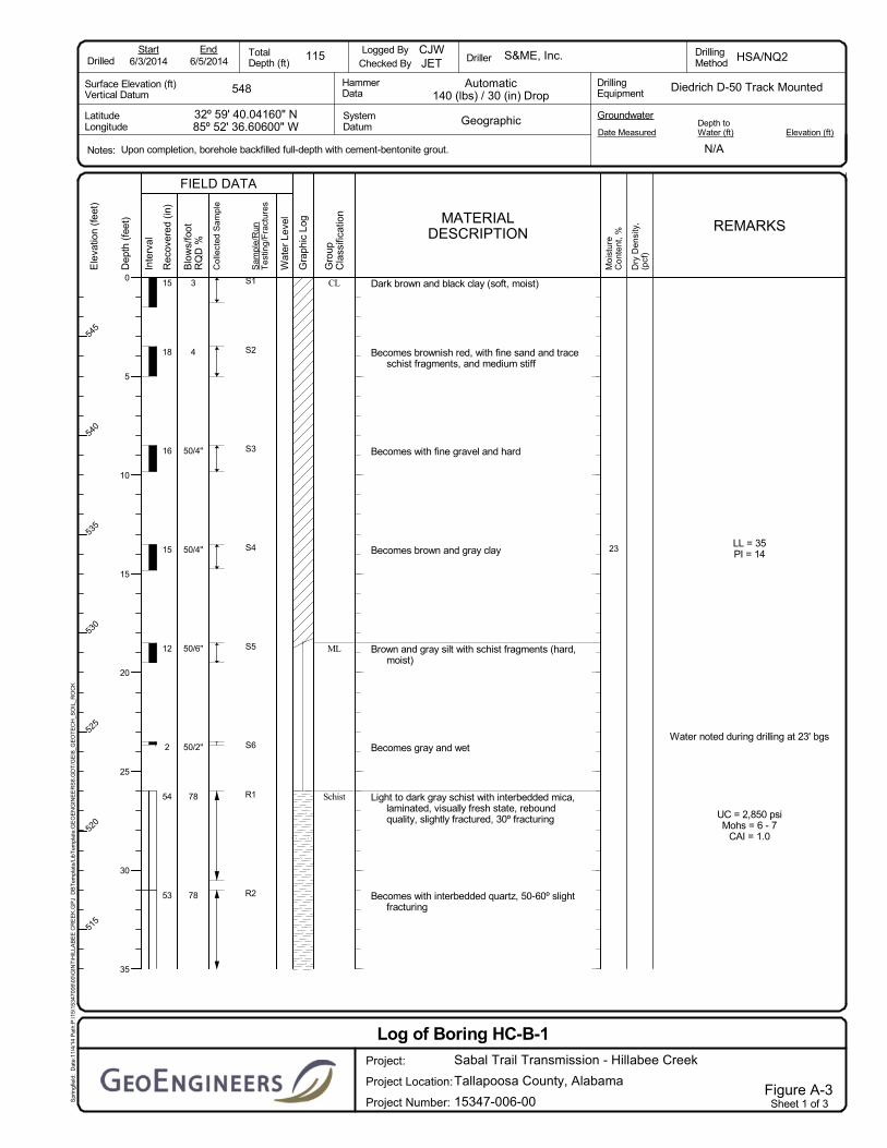
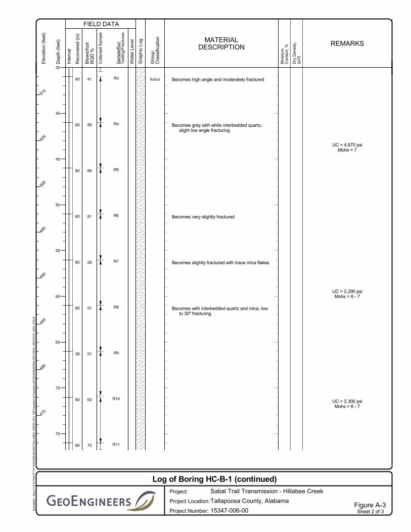
Boring HC-B-1
Drilling operations for boring HC-B-1 were completed on June 5, 2014. Subsurface conditions
encountered at this location consisted of approximately 26 feet of soil overburden consisting primarily of
soft to hard low plasticity clay with fine sand and fine gravel and hard low plasticity silt with schist
fragments. Below approximately 26 feet bgs, bedrock was noted and continuous NQ2 coring techniques
were used to advance the boring to the termination depth at approximately 115 feet bgs. The rock
encountered consisted of typically fair to good quality schist between depths of 26 to 115 feet bgs. The
RQD values in the schist ranged from 28 to 78 percent. The unconfined compressive strength of the rock
ranged from 2,290 pounds per square inch (psi) to 4,670 psi.
Boring HC-B-2
Drilling operations for boring HC-B-2 were completed on July 15, 2014. Subsurface conditions
encountered at this location consisted of approximately 20 feet of soil overburden consisting primarily of

November 17, 2014| Page 4 File No. 15347-006-00
medium stiff to hard low plasticity clay and hard low plasticity silt. Below approximately 20 feet bgs,
bedrock was noted and continuous NQ2 coring techniques were used to advance the boring to the
termination depth at approximately 180 feet bgs. The rock encountered generally consisted of
approximately 160 feet of fair to excellent quality schist with quartz seams. RQD values ranged from 32
to 100 percent from 20 to 65 feet bgs. RQD values were generally greater than 75 percent below 65 feet
bgs with isolated runs of RQD values ranging between 55 and 75 percent. The unconfined compressive
strength of the rock ranged from 980 psi to 2,990 psi.
Boring HC-B-3
Drilling operations for boring HC-B-3 were completed on July 12, 2014. Subsurface conditions
encountered at this location consisted of approximately 54 feet of soil overburden consisting primarily of
hard to very stiff low plasticity silt with fine sand and occasional gravel, overlying highly weathered schist
bedrock to a depth of approximately 64 feet bgs. Below approximately 64 feet bgs, intact bedrock was
noted and continuous NQ2 coring techniques were used to advance the boring to the termination depth
at approximately 245 feet bgs. The rock encountered consisted of approximately 181 feet of typically fair
to excellent quality schist with quartz seams. RQD values in this zone ranged from 65 to 95 percent with
the exception of two (2) isolated core runs from 65 to 70 feet bgs and from 90 to 95 feet bgs where the
RQD values were 18 and 15 percent, respectively. RQD values were generally greater than 90 percent
below depths of 95 feet bgs with two (2) isolated runs with RQD values of 88 percent from 95 to 100 and
120 to 125 feet bgs. The unconfined compressive strength of the rock ranged from 3,040 psi to 10,090
psi.
Boring HC-B-4
Drilling operations for boring HC-B-4 were completed on May 21, 2014. Subsurface conditions
encountered at this location consisted of approximately 35 feet of soil overburden consisting primarily of
medium stiff to very stiff low plasticity clay, dense to very dense fine to coarse sand with mica schist
fragments and varying amounts of clay content. Below approximately 35 feet bgs, bedrock was noted
and continuous NQ2 coring techniques were used to advance the boring to the termination depth at
approximately 160 feet bgs. The rock encountered consisted of approximately 6.5 feet of poor quality
schist with quartz overlying excellent quality schist with quartz with RQD values greater than 90 percent.
The unconfined compressive strength of the rock ranged from 920 psi to 2,950 psi.
3.2.3 Cerchar Abrasivity Testing
CAI tests were performed on rock samples obtained from the borings to evaluate abrasivity of the rock.
The abrasiveness scale is determined by the data presented in Table 1 below. The testing results are
presented in Table 2 below at their respective sample depths.

November 17, 2014| Page 5 File No. 15347-006-00
TABLE 1. CRITERIA FOR THE CERCHAR ABRASIVENESS INDEX
Classification Average CAI (HRC=55)
Very Low Abrasiveness 0.3 – 0.5
Low Abrasiveness 0.5 – 1.0
Medium Abrasiveness 1.0 – 2.0
High Abrasiveness 2.0 – 4.0
Extreme Abrasiveness 4.0 – 6.0
Quartzitic 6.0 – 7.0
TABLE 2. CERCHAR ABRASIVITY INDEX TEST RESULTS
Boring Number Sample Depth (ft) CAI
HC-B-1 26 – 27 1.0
HC-B-2 35 – 40 1.7
HC-B-2 121 1.9
HC-B-3 117 2.7
As shown in Table 2 above, the CAI values for the selected samples range between 1.0 and 2.7, which is medium to high abrasiveness. The Colorado School of Mines supplied the information provided in Table 3, and it depicts a list of referenced rock samples from around the world and their corresponding CAI values.
TABLE 3. REFERENCE LIST OF CERCHAR ABRASIVITY INDICES
Rock Name CAI Comment
Sandstone 0.3 Fontenelle
Limestone 1.13 Midlothian, Texas
Dolometic Limestone 1.1 to 1.5 Chicago, Illinois
Sandstone 1.3 Navajo
Andesite 2.3 Buckskin Tunnel
Quartz Diorite 3.2 Norway
Red Sandstone 3.6 Kentucky
Gneiss 4.1 Atlanta, Georgia
Quartz Gneiss 4.3 40% Quartz
Gneiss 4.4 18% Quartz Norway
Sandstone 4.7 Kentucky
Granite 4.8 Atlanta, Georgia
Granite Gneiss 5.3 13% Quartz
Quartzite 5.9 Norway

November 17, 2014| Page 6 File No. 15347-006-00
3.2.4 Groundwater Conditions
At the time of drilling, groundwater was observed in boring HC-B-1 at a depth of 23 feet bgs, but not in the other borings. Due to the drilling techniques used, the groundwater level can be difficult to measure and will fluctuate over time due to seasonal variations in precipitation.
3.3 Surface Conditions
3.3.1 General
We evaluated the surface conditions in the vicinity of the proposed HDD during our limited site visit to the proposed HDD site on March 20, 2014 and again during our subsurface exploration program. Photographs of site surface conditions along the project alignment are included in Figures 3 and 4.
3.3.2 Surface Description
The proposed HDD alignment trends roughly northwest to southeast (entry to exit), as shown in Figure 2. The proposed entry point is located adjacent to Alabama Power Company’s overhead power line corridor approximately 500 feet northwest of Hillabee Creek within a densely wooded area with somewhat uneven terrain. The ground surface at the entry point is approximately elevation 560 feet (North American Vertical Datum [NAVD] 88).
The ground surface along the HDD alignment, southeastward from entry slopes downward to Hillabee Creek. From the southeast bank of Hillabee Creek, the ground surface along the HDD alignment consists of a series of ridges and ravines before reaching the exit point at approximate elevation 597 feet NAVD 88.
The proposed exit point is located adjacent to Alabama Power Company’s overhead power line corridor approximately 2,040 feet southeast of the Hillabee Creek within a densely wooded area with uneven terrain. The proposed entry and exit points are also located approximately 75 feet north of Alabama Power Company’s overhead power lines.
The proposed pipe fabrication and stringing area extends 1,925 feet southeast of the exit workspace and parallel to Alabama Power Company’s overhead power lines. The fabrication and stringing area will not be of sufficient length to string the carrier pipe in one continuous section. Significant grading of the ground surface and clearing of trees will be required within the stringing area to facilitate positioning the carrier pipe during fabrication and pullback operations.
4.0 LIMITATIONS
We have prepared this report for use by GIE, Sabal Trail Transmission and their authorized agents and other approved members of the design team involved with this project. The report is not intended for use by others, and the information contained herein is not applicable to other sites. The data and report should be provided to prospective contractors, but our report, conclusions and interpretations should not be construed as a warranty of the subsurface conditions. The conclusions and recommendations in this report should be applied in their entirety.
Variations in subsurface conditions are possible between the explorations. Subsurface conditions may also vary with time. A contingency for unanticipated conditions should be included in the project budget
November 17, 2014| Page 7 File No. 15347-006-00
and schedule for such an occurrence. We recommend that sufficient monitoring, testing and consultation be provided by GeoEngineers during construction to confirm that the conditions encountered are consistent with those indicated by the explorations, to provide recommendations for design changes should the conditions revealed during the work differ from those anticipated, and to evaluate whether earthwork and pipeline installation activities comply with contract plans and specifications.
The scope of our services does not include services related to construction safety precautions. Our recommendations are not intended to direct the contractor's methods, techniques, sequences or procedures.
Within the limitations of scope, schedule and budget, our services have been executed in accordance with generally accepted practices in this area at the time the report was prepared. No warranty or other conditions, express, written, or implied, should be understood.
Any electronic form, facsimile or hard copy of the original document (email, text, table and/or figure), if provided, and any attachments are only a copy of the original document. The original document is stored by GeoEngineers, and will serve as the official document of record.
Please refer to Appendix B, titled “Report Limitations and Guidelines for Use,” for additional information pertaining to use of this report.
5.0 REFERENCES
Cerchar – Centre d’ Etudes et Recherches de Chabonnages de France (1986): The Cerchar Abrasiveness Index. – 12 S, Verneuil.
Raymond, D.E., Osborne, W.E., Copeland, C.W. and Neathery, T.L., Alabama Stratigraphy, Geological Survey of Alabama, 1988.
Szabo, et. al., Geologic Map of Alabama, Geological Survey of Alabama, 1:250,000 Scale, 1988.
Scott, J.C., Geologic Map of Russell County, Alabama, 1:63,360 Scale, 1962.
USGS Mineral Resources, U.S. Geological Survey, U.S. Department of the Interior, Mineral Resources On-Line Spatial Data, (http://mrdata.usgs.gov).

FIGU
RE
S

8
0
5
2
7
4
9
1
6
3
Tallapoosa
Clay
UV63
UV22
UV49
UV49
UV49
SABAL TRAIL TRANSMISSION PROJECTVICINITY MAP
HILLABEE CREEK HDDTALLAPOOSA COUNTY, ALABAMA
Figure 1
µ1 0 1 2 3
Miles
Notes:1. The locations of all features shown are approximate.2. This drawing is for information purposes. It is intended toassist in showing features discussed in an attached document.GeoEngineers, Inc. cannot guarantee the accuracy and contentof electronic files. The master file is stored by GeoEngineers, Inc. and will serve as the official record of this communication.Data Sources: ESRI Data & Maps, Street Maps 2008.Imagery from ESRI Data Online.Projection: NAD 1983, UTM Zone 17 North.
Offic
e: SP
RPa
th: P:
\15\15
3470
06\G
IS\Vic
inity
Maps
\Hilla
bee C
reek H
DD.m
xdMa
p Rev
ised:
18 N
ovem
ber 2
014
blan
e
Clay
LeeHarris
TroupCoosa
Coweta
Elmore
Heard
Carroll
Tallapoosa
Randolph
Chambers
TalladegaCleburne FultonSt. Clair
Macon Muscogee
A l a b a m aG e o r g i a
Proposed Sabal Trail Pipeline Alignment
H i l l a b e e
H i l l a b e eC r e e kC r e e k
Tallapoosa River HDD
State Highway 22 HDD
Hillabee Creek HDD
Alexander City

SAND W/ SILT ORGANICSAND OCCASIONAL GRAVEL
10°
12°
58'
142'
SILT W/ SCHIST FRAGMENTS
69/10070/9275/10085/10073/10078/10071/10073/10063/10051/9751/10028/10081/10066/10056/10041/10078/8878/9050/2"
SCHIST W/ INTERBEDDED MICA
50/6"50/4"50/4"
43
CLAY
100/100100/100100/10098/10065/100 83/100100/100
100/100100/100100/100100/100100/100100/100100/100100/100100/100100/100SCHIST W/ QUARTZ SEAMS100/10095/10088/10055/10083/10092/10075/10032/10088/100100/100100/10070/100100/100100/100100/10067/10050/5"
27740
5
CLAY W/ ROCK FRAGMENTSSILT W/ ROCK FRAGMENTS
CLAY W/ ORGANICS
100/100100/100100/100100/10098/100100/100
100/100100/100100/100100/100
100/100
100/100100/100100/100100/100100/100100/100100/100100/100100/10093/100100/100100/100100/100
88/100100/100
92/100100/100
100/10088/10015/10078/10065/10082/10095/10018/6250/2"
SCHIST
50/3"50/2"50/2"50/5"50/5"50/5"50/5"
6850/3"
42232013
SCHIST ROCK FRAGMENTS
SILTY SAND W/ MICA AND WEATHEROCKFRAGMENTS
SILT W/ SAND AND OCCASIONAL GRAVEL
100/100100/100
100/10095/100100/100100/100100/100100/100100/100100/100100/100100/100100/100100/10095/10095/100100/100100/100100/100100/100100/10090/10095/10035/75SAND W/ CLAY AND SCHIST FRAGMENTS
CLAYEY SAND W/ OCCASIONAL MICA SCHIST FRAGMENTS
CLAY W/ ORGANICS
715
8265042
50/4"50/3"0/47
MICA SCHIST W/ QUARTZ
P P PP P P
P P P
P P P P P P PP P P P P P P
P P P P P P PP P P P P P P P P P
MP1.0
MP
2.0
650700
650
600
600
550
550
600
550
6 00
600
600
550
600
600600
650
HILLABEE CREEK
S1TRC369
S4TRC067S4TRC068
S4TRC069
S1TRC214
60'75'
60'
PROPOSEDHDD ENTRY POINTN. 12012009.29117E. 144918.23502LAT. N32.99459793LONG. W85.87685663
225'
300'
191'
PROPOSEDHDD EXIT POINTN. 12010627.54842E. 147255.32979LAT. N32.99110994LONG. W85.86905081
10'HDD PROFILE20' OF COVER
PROPOSED HDDENTRY POINT
PROPOSED HDDEXIT POINT
PROPOSED SABAL TRAILPIPELINE ALIGNMENT
PROPOSED 36" HORIZONTAL DIRECTIONAL DRILL - 2715'
PROPOSED TEMPORARYENTRY WORKSPACE PROPOSED TEMPORARY
1.99 ACRES ODD-SHAPEDEXIT WORKSPACE
PROPERTY LINE (TYP.)
GROUND SURFACE (SURVEY)
HILLABEE CREEK(WATER LEVEL APPROX.)
STREAM (TYP.)
HDD PROFILE20' OF COVER
EXISTING OVERHEADPOWERLINE (TYP.)
PROPOSED PRODUCT PIPESTRINGING AND FABRICATION AREA
TO BE WITHIN AND ALONG TEMPORARYWORKSPACE (1925' LONG)
PERMANENTEASEMENT (TYP.)
TEMPORARYWORKSPACE (TYP.)
PROPOSED 36" HDD PROFILE
HC-B-2HC-B-1 HC-B-3 HC-B-4
DATUM:HORIZONTAL:VERTICAL:
UTM with NAD83 datum, Zone 17, US Foot; Central Meridian 81° WNAVD 88
SABAL TRAIL TRANSMISSIONPROPOSED 36" PIPELINESITE PLAN AND PROFILE
HILLABEE CREEK HDD
Notes:1. The locations of all features shown are approximate.2. This drawing is for information purposes. It is intended to assist in showing features discussed in an attached document.
GeoEngineers, Inc. can not guarantee the accuracy and content of electronic files. The master file is stored by GeoEngineers,Inc. and will serve as the official record of this communication.
3. Refer to the boring logs in the accompanying report for more detailed soil descriptions.4. The utilities shown on the drawing are based on survey data provided by Gulf Interstate Engineering. GeoEngineers, Inc. has
not verified the field location of the existing utilities.
Reference: Ground surface survey, survey data and aerial photo provided by Gulf Interstate Engineering.
HC-B-1
HC-B-2HC-B-3
HC-B-4
ACCESS ROAD (TYP.)
PT2
PC2PT1
PC1
4000' R4000' R
ADDITIONAL TEMPORARYWORKSPACE (TYP.)
Boring Location
Major Contour - 50' IntervalMinor Contour - 10' Interval
TYPE OF SOIL
LEGEND:
RQD/%REC
SPT (N)
TYPE OF ROCK
DISCLAIMER: FOR FERC FINAL SUBMITTAL.THIS DRAWING IS NOT INTENDED FOR CONSTRUCTION.
ISSUED FOR PERMITTINGSHEET NO.
DRAWN BY:
CHECKED BY:
SCALE:
DATE:
DATE:
W.O.:
DRAWINGNUMBER:
REV.
REV. DESCRIPTION DATE
SURVEYED ROAD (TYP.)
S1TRC216
WATERBODYBOUNDARY
1 0 1
Miles
Notes:1. The locations of all features shown are approximate.2. This drawing is for information purposes. It is intendedto assist in showing features discussed in an attached document. GeoEngineers, Inc. cannot guarantee the accuracy and contentof electronic files. The master file is stored by GeoEngineers, Inc.and will serve as the official record of this communication.Projection: NAD 1983 UTM Zone 16N
Sabal Trail Mileposts
Sabal Trail Alignment
Proposed HDD Location
Surface FaultsFault Type
Fault (sense of movement unknown)
Thrust Fault
Alabama GeologyWater
da: Agricola Schist
dch: Camp Hill Granite Gneiss
dmum: Mafic and ultramafic rock
drc: Ropes Creek Amphibolite
drm: Rock Mills Granite Gneiss
dws: Waresville Schist
egn: Elkahatchee Quartz Diorite Gneiss
em: Emuckfaw Group undifferentiated in part
jg: Jacksons Gap Group
kgn: Kowaliga Gneiss
we: Wedowee Group undifferentiated
wec: Cornhouse Schist
weh: Hackneyville Schist
zg: Zana Granite
Offic
e: PO
RTPa
th: P:
\15\
1534
7006
_GIS\
GIS\0
0\MX
D\15
3470
0600
_Hilla
beeC
reekH
DD.m
xdMa
p Rev
ised:
18 N
ovem
ber 2
014
cca
brera
Tallapoosa R iver
Cree
k
H illabe
e Creek
MP 0
MP 1
MP 2
MP 3 MP 4MP 5
MP 6
MP 7
MP 8
MP 9
MP 10
MP 11
MP 12
MP 13
MP 14
MP 15
Talla
poos
a Rive
r
Timberg
ut Cree
k
Josie L
eg Cree
k
jg
emwe
em
kgn
zg
egn
emzg
drm
dws
da
weh
zg
dmum
wec
zg
em zg
em
weh
em
da
zg
weh
zg
drmweh
weh
dmum
weh
zg
weh
weh
weh
zg Dudleyvi lle Rd
Concord Rd
Concord Rd
AL-22
AL-49
AL-38 AL-38
AL-49
AL-49
A L-2
2
AL-38
AL-49
AL-49
AL-49
AL-22
Highway 22 E
Horseshoe BendRd
Hamlet Mill R d
AL-22
5721
79
4444
49
22
49
49
49
22
22
49
49
280
Tal lapoosaTal lapoosa
SessionsSessions
Data Source: Surface faults from Alabama State GeoSpatial Data site,http://gsa.state.al.us/gsa/geologichazards/AL_GIS_Data.htm.Base map from ArcGIS Online. ESRI Maps.Hydrology from USGS National Map.
Geologic MapSabal Trail Transmission Project
Hillabee Creek HDDTallapoosa County, Alabama
Figure 3
Hillabee Creek HDD
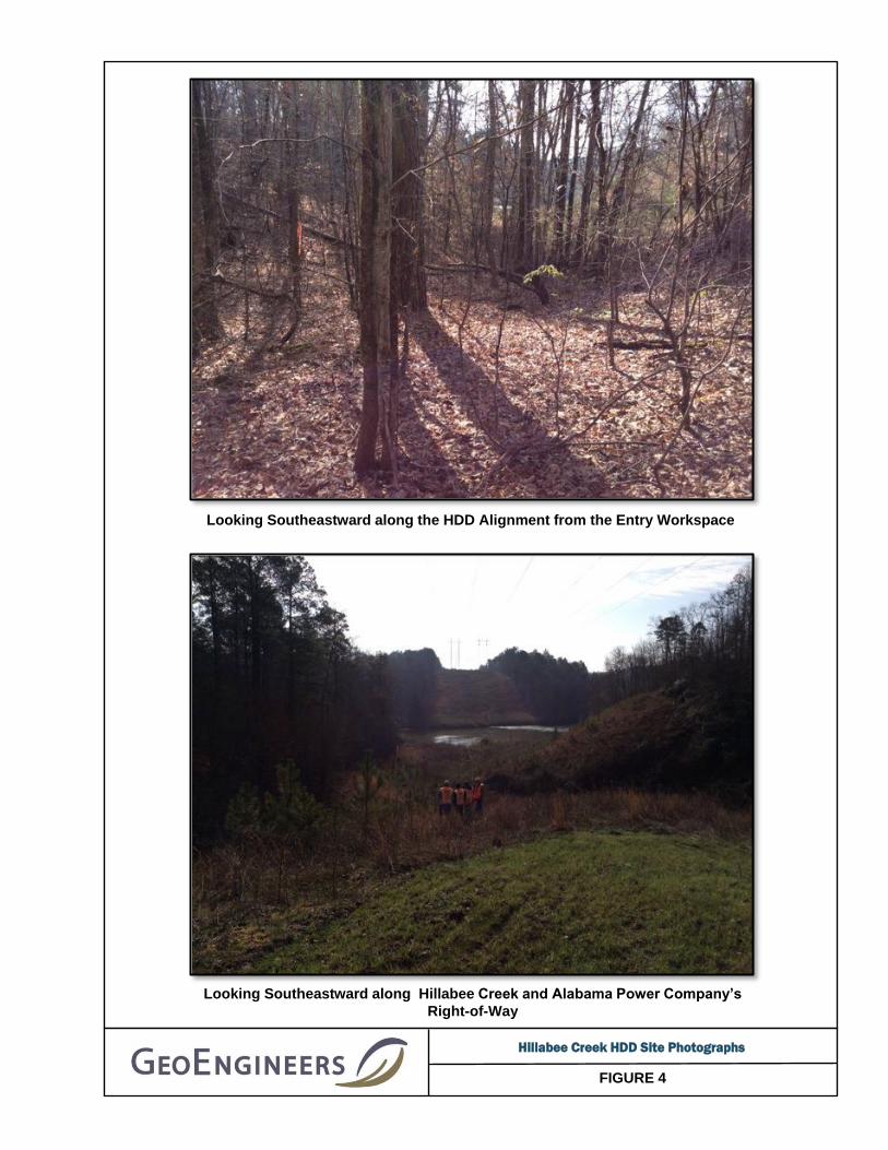
FIGURE 4
Looking Southeastward along the HDD Alignment from the Entry Workspace
Looking Southeastward along Hillabee Creek and Alabama Power Company’s
Right-of-Way
Hillabee Creek HDD Site Photographs
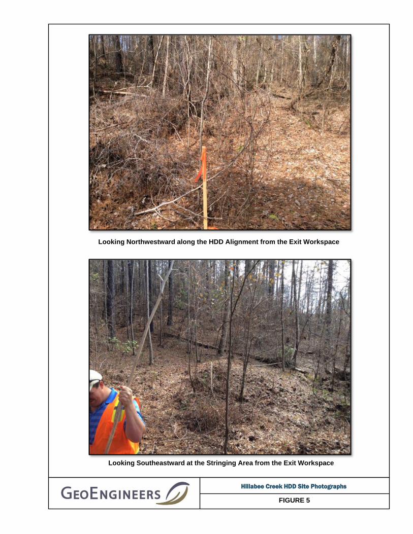
FIGURE 5
Looking Northwestward along the HDD Alignment from the Exit Workspace
Looking Southeastward at the Stringing Area from the Exit Workspace
Hillabee Creek HDD Site Photographs

AP
PE
ND
ICE
S

APPENDIX A Field Explorations and Laboratory Testing
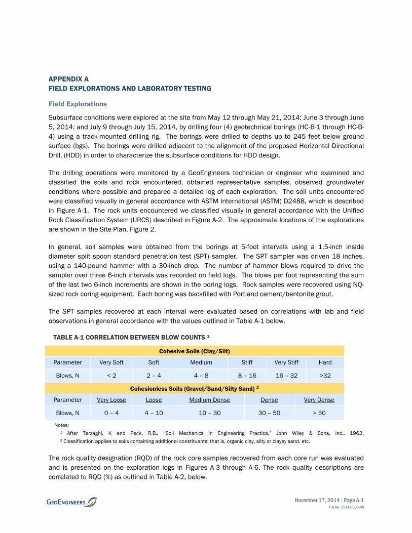
November 17, 2014| Page A-1 File No. 15347-006-00
APPENDIX A
FIELD EXPLORATIONS AND LABORATORY TESTING
Field Explorations
Subsurface conditions were explored at the site from May 12 through May 21, 2014; June 3 through June
5, 2014; and July 9 through July 15, 2014, by drilling four (4) geotechnical borings (HC-B-1 through HC-B-
4) using a track-mounted drilling rig. The borings were drilled to depths up to 245 feet below ground
surface (bgs). The borings were drilled adjacent to the alignment of the proposed Horizontal Directional
Drill, (HDD) in order to characterize the subsurface conditions for HDD design.
The drilling operations were monitored by a GeoEngineers technician or engineer who examined and
classified the soils and rock encountered, obtained representative samples, observed groundwater
conditions where possible and prepared a detailed log of each exploration. The soil units encountered
were classified visually in general accordance with ASTM International (ASTM) D2488, which is described
in Figure A-1. The rock units encountered we classified visually in general accordance with the Unified
Rock Classification System (URCS) described in Figure A-2. The approximate locations of the explorations
are shown in the Site Plan, Figure 2.
In general, soil samples were obtained from the borings at 5-foot intervals using a 1.5-inch inside
diameter split spoon standard penetration test (SPT) sampler. The SPT sampler was driven 18 inches,
using a 140-pound hammer with a 30-inch drop. The number of hammer blows required to drive the
sampler over three 6-inch intervals was recorded on field logs. The blows per foot representing the sum
of the last two 6-inch increments are shown in the boring logs. Rock samples were recovered using NQ-
sized rock coring equipment. Each boring was backfilled with Portland cement/bentonite grout.
The SPT samples recovered at each interval were evaluated based on correlations with lab and field
observations in general accordance with the values outlined in Table A-1 below.
TABLE A-1 CORRELATION BETWEEN BLOW COUNTS 1
Cohesive Soils (Clay/Silt)
Parameter Very Soft Soft Medium Stiff Very Stiff Hard
Blows, N < 2 2 – 4 4 – 8 8 – 16 16 – 32 >32
Cohesionless Soils (Gravel/Sand/Silty Sand) 2
Parameter Very Loose Loose Medium Dense Dense Very Dense
Blows, N 0 – 4 4 – 10 10 – 30 30 – 50 > 50
Notes:
1 After Terzaghi, K and Peck, R.B., “Soil Mechanics in Engineering Practice,” John Wiley & Sons, Inc., 1962.
2 Classification applies to soils containing additional constituents; that is, organic clay, silty or clayey sand, etc.
The rock quality designation (RQD) of the rock core samples recovered from each core run was evaluated
and is presented on the exploration logs in Figures A-3 through A-6. The rock quality descriptions are
correlated to RQD (%) as outlined in Table A-2, below.
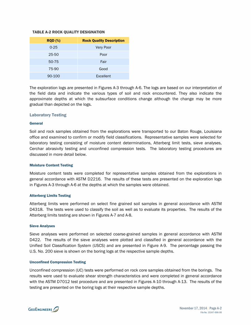
November 17, 2014| Page A-2 File No. 15347-006-00
TABLE A-2 ROCK QUALITY DESIGNATION
RQD (%) Rock Quality Description
0-25 Very Poor
25-50 Poor
50-75 Fair
75-90 Good
90-100 Excellent
The exploration logs are presented in Figures A-3 through A-6. The logs are based on our interpretation of
the field data and indicate the various types of soil and rock encountered. They also indicate the
approximate depths at which the subsurface conditions change although the change may be more
gradual than depicted on the logs.
Laboratory Testing
General
Soil and rock samples obtained from the explorations were transported to our Baton Rouge, Louisiana
office and examined to confirm or modify field classifications. Representative samples were selected for
laboratory testing consisting of moisture content determinations, Atterberg limit tests, sieve analyses,
Cerchar abrasivity testing and unconfined compression tests. The laboratory testing procedures are
discussed in more detail below.
Moisture Content Testing
Moisture content tests were completed for representative samples obtained from the explorations in
general accordance with ASTM D2216. The results of these tests are presented on the exploration logs
in Figures A-3 through A-6 at the depths at which the samples were obtained.
Atterberg Limits Testing
Atterberg limits were performed on select fine grained soil samples in general accordance with ASTM
D4318. The tests were used to classify the soil as well as to evaluate its properties. The results of the
Atterberg limits testing are shown in Figures A-7 and A-8.
Sieve Analyses
Sieve analyses were performed on selected coarse-grained samples in general accordance with ASTM
D422. The results of the sieve analyses were plotted and classified in general accordance with the
Unified Soil Classification System (USCS) and are presented in Figure A-9. The percentage passing the
U.S. No. 200 sieve is shown on the boring logs at the respective sample depths.
Unconfined Compression Testing
Unconfined compression (UC) tests were performed on rock core samples obtained from the borings. The
results were used to evaluate shear strength characteristics and were completed in general accordance
with the ASTM D7012 test procedure and are presented in Figures A-10 through A-13. The results of the
testing are presented on the boring logs at their respective sample depths.

November 17, 2014| Page A-3 File No. 15347-006-00
Cerchar Abrasivity Index Testing
Cerchar Abrasivity Index tests were performed on rock samples obtained from the borings. The tests
were used to evaluate the abrasivity of the rock, and were completed in general accordance with ASTM
D7625. The results of the testing as well as reference values are presented in the boring logs and
Section 3.2.3.

Blowcount is recorded for driven samplers as the numberof blows required to advance sampler 12 inches (ordistance noted). See exploration log for hammer weightand drop.
A "P" indicated sampler pused using the weight of the drill rig.
"WOH" indicates sampler pushed using the weight of the 140-pound SPT hammer.
NOTE: The reader must refer to the discussion in the report text and the logs of explorations for a proper understanding of subsurface conditions.Descriptions on the logs apply only at the specific exploration locations and at the time the explorations were made; they are not warranted to berepresentative of subsurface conditions at other locations or times.
Perched water observed at time ofexploration
SYMBOLS TYPICAL
KEY TO EXPLORATION LOGS
CC
CR
Groundwater observed at time ofexploration
Approximate location of soil stratachange within a geologic soil unit
Laboratory / Field Tests%FALCACPCSDSHAMCMDOCPMPPSATXUCVS
Standard Penetration Test (SPT)
Bulk or grab
Asphalt Concrete
Measured groundwater level inexploration, well, or piezometer
DESCRIPTIONSLETTER
Distinct contact between soil strata orgeologic units
Material Description Contact
Approximate location of soil stratachange within a geologic soil unit
Distinct contact between soil strata orgeologic units
TS
ADDITIONAL MATERIAL SYMBOLS
AC
Cement Concrete
Sampler Symbol Descriptions
GRAPH
Topsoil/Forest Duff/Sod
Percent finesAtterberg limitsChemical analysisLaboratory compaction testConsolidation testDirect shearHydrometer analysisMoisture contentMoisture content and dry densityOrganic contentPermeability or hydraulic conductivityPocket penetrometerSieve analysisTriaxial compressionUnconfined compressionVane shear
Piston
Crushed Rock/Quarry Spalls
Graphic Log Contact
GC
PT
OH
CH
MH
OL
ORGANIC CLAYS AND SILTS OFMEDIUM TO HIGH PLASTICITY
GM
GP
GW
DESCRIPTIONSTYPICAL
LETTERGRAPH
(APPRECIABLE AMOUNTOF FINES)
MORE THAN 50%RETAINED ON NO.
200 SIEVE
SYMBOLSMAJOR DIVISIONS
WELL-GRADED SANDS, GRAVELLYSANDS
SP
PEAT, HUMUS, SWAMP SOILS WITHHIGH ORGANIC CONTENTS
INORGANIC CLAYS OF HIGHPLASTICITY
(LITTLE OR NO FINES)
ORGANIC SILTS AND ORGANICSILTY CLAYS OF LOW PLASTICITY
INORGANIC CLAYS OF LOW TOMEDIUM PLASTICITY, GRAVELLYCLAYS, SANDY CLAYS, SILTY CLAYS,LEAN CLAYS
CLAYEY SANDS, SAND - CLAYMIXTURES
SILTY SANDS, SAND - SILTMIXTURES
CLAYEY GRAVELS, GRAVEL - SAND -CLAY MIXTURES
POORLY-GRADED GRAVELS,GRAVEL - SAND MIXTURES
ML
SC
SM
NOTE: Multiple symbols are used to indicate borderline or dual soil classifications
MORE THAN 50%PASSING NO. 200
SIEVE
MORE THAN 50%OF COARSEFRACTION
PASSING NO. 4SIEVE
CLEAN SANDS
GRAVELS WITHFINES
CLEANGRAVELS
HIGHLY ORGANIC SOILS
SILTSAND
CLAYS
SILTSAND
CLAYS
SANDAND
SANDYSOILS
GRAVELAND
GRAVELLYSOILS
(LITTLE OR NO FINES)
FINEGRAINED
SOILS
COARSEGRAINED
SOILS
SW
MORE THAN 50%OF COARSEFRACTION
RETAINED ON NO.4 SIEVE
CL
WELL-GRADED GRAVELS, GRAVEL -SAND MIXTURES
POORLY-GRADED SANDS,GRAVELLY SAND
INORGANIC SILTS, ROCK FLOUR,CLAYEY SILTS WITH SLIGHTPLASTICITY
INORGANIC SILTS, MICACEOUS ORDIATOMACEOUS SILTY SOILS
SILTY GRAVELS, GRAVEL - SAND -SILT MIXTURES
(APPRECIABLE AMOUNTOF FINES)
SOIL CLASSIFICATION CHART
LIQUID LIMITGREATER THAN 50
LIQUID LIMITLESS THAN 50
SANDS WITHFINES
Shelby tube
Direct-Push
FIGURE A-1
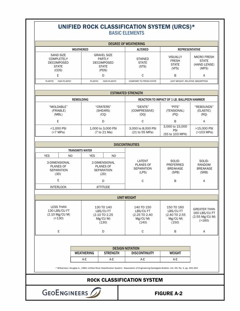
FIGURE A-2
ROCK CLASSIFICATION SYSTEM
UNIFIED ROCK CLASSIFICATION SYSTEM (URCS)* BASIC ELEMENTS
DEGREE OF WEATHERING
WEATHERED ALTERED REPRESENTATIVE SAND SIZE
COMPLETELY DECOMPOSED
STATE (CDS)
GRAVEL SIZE PARTLY
DECOMPOSED STATE (PDS)
STAINED STATE (STS)
VISUALLY FRESH STATE (VFS)
MICRO FRESH STATE
(HAND LENSE) (MFS)
E D C B A
PLASTIC NON-PLASTIC PLASTIC NON-PLASTIC COMPARE TO FRESH STATE UNIT WEIGHT, RELATIVE ABSORPTION
ESTIMATED STRENGTH
REMOLDING REACTION TO IMPACT OF 1 LB. BALLPEEN HAMMER
“MOLDABLE” (FRIABLE)
(MBL)
“CRATERS” (SHEARS)
(CQ)
“DENTS” (COMPRESSIVE)
(DQ)
“PITS” (TENSIONAL)
(PQ)
“REBOUNDS” (ELASTIC)
(RQ)
E D C B A
<1,000 PSI (<7 MPa)
1,000 to 3,000 PSI (7 to 21 Ma)
3,000 to 8,000 PSI (21 to 55 MPa)
3,000 to 15,000 PSI
(55 to 103 MPA)
>15,000 PSI (>103 MPa)
DISCONTINUITIES
TRANSMITS WATER
LATENT PLANES OF SEPARATION
(LPS)
SOLID- PREFERRED BREAKAGE
(SPB)
SOLID- RANDOM
BREAKAGE (SRB)
YES NO YES NO
3-DIMENSIONAL PLANES OF
SEPARATION (3D)
2-DIMENSIONAL PLANES OF
SEPARATION (2D)
E D C B A
INTERLOCK ATTITUDE
UNIT WEIGHT
LESS THAN 130 LBS/CU FT (2.10 Mg/CU M)
(<130)
130 TO 140 LBS/CU FT
(2.10 TO 2.25 Mg/CU M)
(130)
140 TO 150 LBS/CU FT
(2.25 TO 2.40 Mg/CU M)
(140)
150 TO 160 LBS/CU FT
(2.40 TO 2.55 Mg/CU M)
(150)
GREATER THAN 160 LBS/CU FT (2.55 Mg/CU M)
(>160)
E D C B A
DESIGN NOTATION
WEATHERING STRENGTH DISCONTINUITY WEIGHT
A-E A-E A-E A-E
* Williamson, Douglas A., 1984, Unified Rock Classification System: Association of Engineering Geologists Bulletin, Vol. XXI, No. 3, pp. 345-354
CL
ML
Schist
15
18
16
15
12
2
54
53
3
4
50/4"
50/4"
50/6"
50/2"
S1
S2
S3
S4
S5
S6
R1
R2
78
78
Dark brown and black clay (soft, moist)
Becomes brownish red, with fine sand and traceschist fragments, and medium stiff
Becomes with fine gravel and hard
Becomes brown and gray clay
Brown and gray silt with schist fragments (hard,moist)
Becomes gray and wet
Light to dark gray schist with interbedded mica,laminated, visually fresh state, reboundquality, slightly fractured, 30º fracturing
Becomes with interbedded quartz, 50-60º slightfracturing
23LL = 35PI = 14
Water noted during drilling at 23' bgs
UC = 2,850 psiMohs = 6 - 7
CAI = 1.0
TotalDepth (ft)
HammerData
SystemDatum
StartChecked ByLogged By
JETDrillingMethodDrilled
Notes:
CJW
Surface Elevation (ft)Vertical Datum
HSA/NQ2Driller
GroundwaterDepth toWater (ft)Date Measured
Diedrich D-50 Track Mounted
Elevation (ft)
DrillingEquipment
LatitudeLongitude
32º 59' 40.04160" N85º 52' 36.60600" W Geographic
115
Upon completion, borehole backfilled full-depth with cement-bentonite grout.
Automatic140 (lbs) / 30 (in) Drop
548
N/A
S&ME, Inc.6/3/2014End
6/5/2014
Sheet 1 of 3Figure A-3
Log of Boring HC-B-1
Project Location:
Project:
Project Number:
Sabal Trail Transmission - Hillabee Creek
15347-006-00
Tallapoosa County, Alabama
Spr
ingf
ield
: D
ate:
11/4
/14
Pat
h:P
:\15\
1534
7006
\00\
GIN
T\H
ILLA
BE
E C
RE
EK
.GP
J D
BT
empl
ate/
LibT
empl
ate:
GE
OE
NG
INE
ER
S8.
GD
T/G
EI8
_GE
OT
EC
H_S
OIL
_RO
CK
FIELD DATA
Ele
vatio
n (f
eet)
545
540
535
530
525
520
515
Dep
th (
feet
)
0
5
10
15
20
25
30
35
Col
lect
ed S
ampl
e
Gro
upC
lass
ifica
tion
Inte
rval
Rec
over
ed (
in)
Blo
ws/
foot
RQ
D %
Sam
ple/
Run
Tes
ting
/Fra
ctur
es
MATERIALDESCRIPTION
Gra
phic
Log
Wat
er L
evel
Moi
stur
eC
onte
nt,
%
Dry
Den
sity
,(p
cf)
REMARKS
Schist60
60
60
60
60
60
58
60
60
R3
R4
R5
R6
R7
R8
R9
R10
R11
41
56
66
81
28
51
51
63
73
Becomes high angle and moderately fractured
Becomes gray with white interbedded quartz,slight low angle fracturing
Becomes very slightly fractured
Becomes slightly fractured with trace mica flakes
Becomes with interbedded quartz and mica, lowto 30º fracturing
UC = 4,670 psiMohs = 7
UC = 2,290 psiMohs = 6 - 7
UC = 2,300 psiMohs = 6 - 7
Sheet 2 of 3Figure A-3
Log of Boring HC-B-1 (continued)
Project Location:
Project:
Project Number:
Sabal Trail Transmission - Hillabee Creek
15347-006-00
Tallapoosa County, Alabama
Spr
ingf
ield
: D
ate:
11/4
/14
Pat
h:P
:\15\
1534
7006
\00\
GIN
T\H
ILLA
BE
E C
RE
EK
.GP
J D
BT
empl
ate/
LibT
empl
ate:
GE
OE
NG
INE
ER
S8.
GD
T/G
EI8
_GE
OT
EC
H_S
OIL
_RO
CK
FIELD DATA
Ele
vatio
n (f
eet)
510
505
500
495
490
485
480
475
Dep
th (
feet
)
35
40
45
50
55
60
65
70
75
Col
lect
ed S
ampl
e
Gro
upC
lass
ifica
tion
Inte
rval
Rec
over
ed (
in)
Blo
ws/
foot
RQ
D %
Sam
ple/
Run
Tes
ting
/Fra
ctur
es
MATERIALDESCRIPTION
Gra
phic
Log
Wat
er L
evel
Moi
stur
eC
onte
nt,
%
Dry
Den
sity
,(p
cf)
REMARKS
Schist
60
60
60
60
48
55
60
R12
R13
R14
R15
R16
R17
R18
71
78
73
85
75
70
69
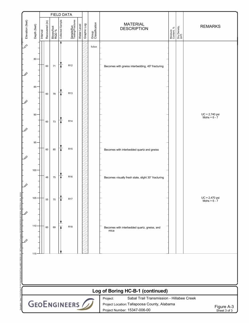
Becomes with gneiss interbedding, 45º fracturing
Becomes with interbedded quartz and gneiss
Becomes visually fresh state, slight 30° fracturing
Becomes with interbedded quartz, gneiss, andmica
UC = 2,740 psiMohs = 6 - 7
UC = 2,470 psiMohs = 6 - 7
Sheet 3 of 3Figure A-3
Log of Boring HC-B-1 (continued)
Project Location:
Project:
Project Number:
Sabal Trail Transmission - Hillabee Creek
15347-006-00
Tallapoosa County, Alabama
Spr
ingf
ield
: D
ate:
11/4
/14
Pat
h:P
:\15\
1534
7006
\00\
GIN
T\H
ILLA
BE
E C
RE
EK
.GP
J D
BT
empl
ate/
LibT
empl
ate:
GE
OE
NG
INE
ER
S8.
GD
T/G
EI8
_GE
OT
EC
H_S
OIL
_RO
CK
FIELD DATA
Ele
vatio
n (f
eet)
470
465
460
455
450
445
440
435
Dep
th (
feet
)
80
85
90
95
100
105
110
115
Col
lect
ed S
ampl
e
Gro
upC
lass
ifica
tion
Inte
rval
Rec
over
ed (
in)
Blo
ws/
foot
RQ
D %
Sam
ple/
Run
Tes
ting
/Fra
ctur
es
MATERIALDESCRIPTION
Gra
phic
Log
Wat
er L
evel
Moi
stur
eC
onte
nt,
%
Dry
Den
sity
,(p
cf)
REMARKS

CL
ML
CL
Schist
12
18
9
10
4
54
60
60
60
5
40
7
27
50/5"
S1
S2
S3
S4
S5
R1
R2
R3
R4
67
100
100
100
Brownish red clay with organics (medium stiff,dry)
Brownish red silt with rock fragments (hard, dry)
Brownish red clay with rock fragments (mediumstiff, moist)
Becomes with weathered rock fragments andvery stiff
Becomes hard
Gray schist with quartz seams, stained state tovisually fresh state, dent quality, and 3Ddiscontinuities
Becomes gray schist with quartz interbeds,rebound quality, and solid random breakage
19
Rough drilling
PI = 9LL = 31
UC = 2,990 psiMohs = 2 - 3
UC = 1,860 psiMohs = 3
TotalDepth (ft)
HammerData
SystemDatum
StartChecked ByLogged By
DJJDrillingMethodDrilled
Notes:
NWH
Surface Elevation (ft)Vertical Datum
HSA/NQ2Driller
GroundwaterDepth toWater (ft)Date Measured
Diedrich D-50 Track Mounted
Elevation (ft)
DrillingEquipment
LatitudeLongitude
32º 59' 35.17800" N85º 52' 25.80600" W Geographic
180
Upon completion, borehole backfilled full-depth with cement-bentonite grout.
Automatic140 (lbs) / 30 (in) Drop
573
N/A
S&ME, Inc.7/13/2014End
7/15/2014
Sheet 1 of 5Figure A-4
Log of Boring HC-B-2
Project Location:
Project:
Project Number:
Sabal Trail Transmission - Hillabee Creek
15347-006-00
Tallapoosa County, Alabama
Spr
ingf
ield
: D
ate:
11/4
/14
Pat
h:P
:\15\
1534
7006
\00\
GIN
T\H
ILLA
BE
E C
RE
EK
.GP
J D
BT
empl
ate/
LibT
empl
ate:
GE
OE
NG
INE
ER
S8.
GD
T/G
EI8
_GE
OT
EC
H_S
OIL
_RO
CK
FIELD DATA
Ele
vatio
n (f
eet)
570
565
560
555
550
545
540
Dep
th (
feet
)
0
5
10
15
20
25
30
35
Col
lect
ed S
ampl
e
Gro
upC
lass
ifica
tion
Inte
rval
Rec
over
ed (
in)
Blo
ws/
foot
RQ
D %
Sam
ple/
Run
Tes
ting
/Fra
ctur
es
MATERIALDESCRIPTION
Gra
phic
Log
Wat
er L
evel
Moi
stur
eC
onte
nt,
%
Dry
Den
sity
,(p
cf)
REMARKS
60
60
60
60
60
60
60
60
R5
R6
R7
R8
R9
R10
R11
R12
70
100
100
88
32
75
92
83
Becomes stained state to visually fresh state,and 3D discontinuitites
Becomes gray schist, visually fresh state,rebound quality, and solid random breakage
Becomes pit quality, 3D discontinuities
Becomes rebound quality
Becomes with 2D discontinuities
CAI = 1.7
UC = 1,870 psiMohs = 2 - 3
UC = 1,850 psiMohs = 3
Sheet 2 of 5Figure A-4
Log of Boring HC-B-2 (continued)
Project Location:
Project:
Project Number:
Sabal Trail Transmission - Hillabee Creek
15347-006-00
Tallapoosa County, Alabama
Spr
ingf
ield
: D
ate:
11/4
/14
Pat
h:P
:\15\
1534
7006
\00\
GIN
T\H
ILLA
BE
E C
RE
EK
.GP
J D
BT
empl
ate/
LibT
empl
ate:
GE
OE
NG
INE
ER
S8.
GD
T/G
EI8
_GE
OT
EC
H_S
OIL
_RO
CK
FIELD DATA
Ele
vatio
n (f
eet)
535
530
525
520
515
510
505
500
Dep
th (
feet
)
35
40
45
50
55
60
65
70
75
Col
lect
ed S
ampl
e
Gro
upC
lass
ifica
tion
Inte
rval
Rec
over
ed (
in)
Blo
ws/
foot
RQ
D %
Sam
ple/
Run
Tes
ting
/Fra
ctur
es
MATERIALDESCRIPTION
Gra
phic
Log
Wat
er L
evel
Moi
stur
eC
onte
nt,
%
Dry
Den
sity
,(p
cf)
REMARKS
60
60
60
60
60
60
60
60
R13
R14
R15
R16
R17
R18
R19
R20
55
88
95
100
100
100
100
100
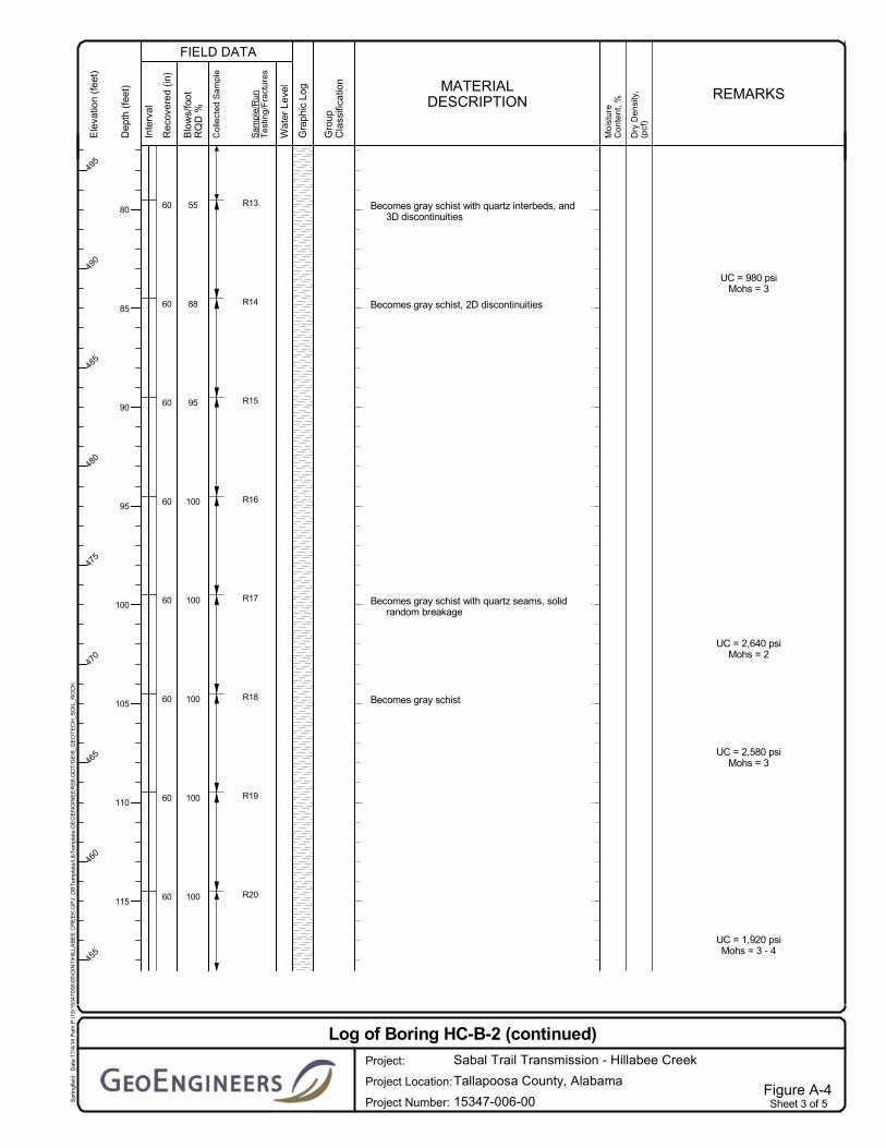
Becomes gray schist with quartz interbeds, and3D discontinuities
Becomes gray schist, 2D discontinuities
Becomes gray schist with quartz seams, solidrandom breakage
Becomes gray schist
UC = 980 psiMohs = 3
UC = 2,640 psiMohs = 2
UC = 2,580 psiMohs = 3
UC = 1,920 psiMohs = 3 - 4
Sheet 3 of 5Figure A-4
Log of Boring HC-B-2 (continued)
Project Location:
Project:
Project Number:
Sabal Trail Transmission - Hillabee Creek
15347-006-00
Tallapoosa County, Alabama
Spr
ingf
ield
: D
ate:
11/4
/14
Pat
h:P
:\15\
1534
7006
\00\
GIN
T\H
ILLA
BE
E C
RE
EK
.GP
J D
BT
empl
ate/
LibT
empl
ate:
GE
OE
NG
INE
ER
S8.
GD
T/G
EI8
_GE
OT
EC
H_S
OIL
_RO
CK
FIELD DATA
Ele
vatio
n (f
eet)
495
490
485
480
475
470
465
460
455
Dep
th (
feet
)
80
85
90
95
100
105
110
115
Col
lect
ed S
ampl
e
Gro
upC
lass
ifica
tion
Inte
rval
Rec
over
ed (
in)
Blo
ws/
foot
RQ
D %
Sam
ple/
Run
Tes
ting
/Fra
ctur
es
MATERIALDESCRIPTION
Gra
phic
Log
Wat
er L
evel
Moi
stur
eC
onte
nt,
%
Dry
Den
sity
,(p
cf)
REMARKS
60
60
60
60
60
60
60
60
60
R21
R22
R23
R24
R25
R26
R27
R28
R29
100
100
100
100
100
100
100
83
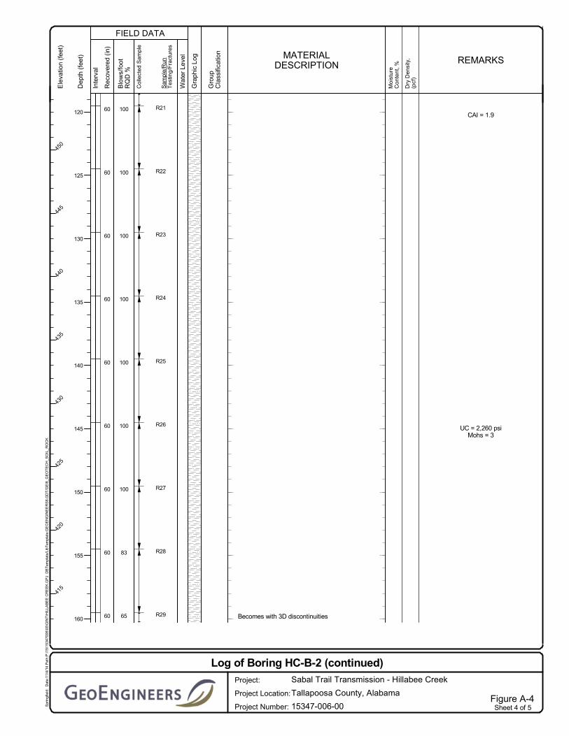
65 Becomes with 3D discontinuities
CAI = 1.9
UC = 2,260 psiMohs = 3
Sheet 4 of 5Figure A-4
Log of Boring HC-B-2 (continued)
Project Location:
Project:
Project Number:
Sabal Trail Transmission - Hillabee Creek
15347-006-00
Tallapoosa County, Alabama
Spr
ingf
ield
: D
ate:
11/4
/14
Pat
h:P
:\15\
1534
7006
\00\
GIN
T\H
ILLA
BE
E C
RE
EK
.GP
J D
BT
empl
ate/
LibT
empl
ate:
GE
OE
NG
INE
ER
S8.
GD
T/G
EI8
_GE
OT
EC
H_S
OIL
_RO
CK
FIELD DATA
Ele
vatio
n (f
eet)
450
445
440
435
430
425
420
415
Dep
th (
feet
)
120
125
130
135
140
145
150
155
160
Col
lect
ed S
ampl
e
Gro
upC
lass
ifica
tion
Inte
rval
Rec
over
ed (
in)
Blo
ws/
foot
RQ
D %
Sam
ple/
Run
Tes
ting
/Fra
ctur
es
MATERIALDESCRIPTION
Gra
phic
Log
Wat
er L
evel
Moi
stur
eC
onte
nt,
%
Dry
Den
sity
,(p
cf)
REMARKS

60
60
60
5
R30
R31
R32
R33
98
100
100
100
Becomes gray schist with quartz seams and 2Ddiscontinuities
UC = 2,960 psiMohs = 2 - 3
Sheet 5 of 5Figure A-4
Log of Boring HC-B-2 (continued)
Project Location:
Project:
Project Number:
Sabal Trail Transmission - Hillabee Creek
15347-006-00
Tallapoosa County, Alabama
Spr
ingf
ield
: D
ate:
11/4
/14
Pat
h:P
:\15\
1534
7006
\00\
GIN
T\H
ILLA
BE
E C
RE
EK
.GP
J D
BT
empl
ate/
LibT
empl
ate:
GE
OE
NG
INE
ER
S8.
GD
T/G
EI8
_GE
OT
EC
H_S
OIL
_RO
CK
FIELD DATA
Ele
vatio
n (f
eet)
410
405
400
395
Dep
th (
feet
)
165
170
175
180
Col
lect
ed S
ampl
e
Gro
upC
lass
ifica
tion
Inte
rval
Rec
over
ed (
in)
Blo
ws/
foot
RQ
D %
Sam
ple/
Run
Tes
ting
/Fra
ctur
es
MATERIALDESCRIPTION
Gra
phic
Log
Wat
er L
evel
Moi
stur
eC
onte
nt,
%
Dry
Den
sity
,(p
cf)
REMARKS

SP-SM
ML
SM
12
14
15
16
8
18
5
5
8
13
20
23
42
50/3"
68
50/5"
50/5"
50/5"
S1
S2
S3
S4
S5
S6
S7
S8
S9
Reddish brown fine sand with silt, organics, andoccasional gravel (medium dense, dry)
Reddish brown silt with fine sand and occasionalgravel (very stiff, dry)
Becomes with mica
Becomes hard
Becomes with weathered rock fragments
Becomes reddish brown silt with fine sand, mica,and weathered rock fragments
Reddish brown silty fine to coarse sand with micaand weathered rock fragments (very dense,
9PI = 4
LL = 32
TotalDepth (ft)
HammerData
SystemDatum
StartChecked ByLogged By
JETDrillingMethodDrilled
Notes:
NWH
Surface Elevation (ft)Vertical Datum
HSA/NQ2Driller
GroundwaterDepth toWater (ft)Date Measured
Diedrich D-50 Track Mounted
Elevation (ft)
DrillingEquipment
LatitudeLongitude
32° 59' 30.04080" N85° 52' 13.77120" W Geographic
245
Upon completion, borehole backfilled full-depth with cement-bentonite grout.
Automatic140 (lbs) / 30 (in) Drop
632
N/A
S&ME, Inc.7/9/2014End
7/12/2014
Sheet 1 of 6Figure A-5
Log of Boring HC-B-3
Project Location:
Project:
Project Number:
Sabal Trail Transmission - Hillabee Creek
15347-006-00
Tallapoosa County, Alabama
Spr
ingf
ield
: D
ate:
11/4
/14
Pat
h:P
:\15\
1534
7006
\00\
GIN
T\H
ILLA
BE
E C
RE
EK
.GP
J D
BT
empl
ate/
LibT
empl
ate:
GE
OE
NG
INE
ER
S8.
GD
T/G
EI8
_GE
OT
EC
H_S
OIL
_RO
CK
FIELD DATA
Ele
vatio
n (f
eet)
630
625
620
615
610
605
600
595
Dep
th (
feet
)
0
5
10
15
20
25
30
35
40
Col
lect
ed S
ampl
e
Gro
upC
lass
ifica
tion
Inte
rval
Rec
over
ed (
in)
Blo
ws/
foot
RQ
D %
Sam
ple/
Run
Tes
ting
/Fra
ctur
es
MATERIALDESCRIPTION
Gra
phic
Log
Wat
er L
evel
Moi
stur
eC
onte
nt,
%
Dry
Den
sity
,(p
cf)
REMARKS

Schist
11
7
7
3
0
37
60
60
60
60
50/5"
50/2"
50/2"
50/3"
50/2"
S10
S11
S12
S13
S14
R1
R2
R3
R4
R5
18
95
82
65
78
dry)
Becomes reddish brown silty fine to coarse sand
Gray weathered schist rock fragments
No recovery
Gray schist, partially decomposed state tovisually fresh state, pit quality, 3Ddiscontinuities
Becomes visually fresh state, rebound quality,and solid random breakage
Becomes with quartz seams, stained state tovisually fresh state, and 3D discontinuities
Becomes gray schist, stained state to visuallyfresh state, rebound quality, 2Ddiscontinuities
Becomes visually fresh state, 3D discontinuities,and with 45º fractures with water stains
8 % Fines = 22
HSA refusal
UC = 4,320 psiMohs = 3
UC = 4,250 psiMohs = 3 - 4
Sheet 2 of 6Figure A-5
Log of Boring HC-B-3 (continued)
Project Location:
Project:
Project Number:
Sabal Trail Transmission - Hillabee Creek
15347-006-00
Tallapoosa County, Alabama
Spr
ingf
ield
: D
ate:
11/4
/14
Pat
h:P
:\15\
1534
7006
\00\
GIN
T\H
ILLA
BE
E C
RE
EK
.GP
J D
BT
empl
ate/
LibT
empl
ate:
GE
OE
NG
INE
ER
S8.
GD
T/G
EI8
_GE
OT
EC
H_S
OIL
_RO
CK
FIELD DATA
Ele
vatio
n (f
eet)
590
585
580
575
570
565
560
555
550
545
Dep
th (
feet
)
40
45
50
55
60
65
70
75
80
85
Col
lect
ed S
ampl
e
Gro
upC
lass
ifica
tion
Inte
rval
Rec
over
ed (
in)
Blo
ws/
foot
RQ
D %
Sam
ple/
Run
Tes
ting
/Fra
ctur
es
MATERIALDESCRIPTION
Gra
phic
Log
Wat
er L
evel
Moi
stur
eC
onte
nt,
%
Dry
Den
sity
,(p
cf)
REMARKS

60
60
60
60
60
60
60
60
60
R6
R7
R8
R9
R10
R11
R12
R13
R14
R15
15
88
100
100
92
100
88
100
100
Becomes stained state to visually fresh state,with 45º to 60º fractures, horizontal fractures,and water stains
Becomes with quartz seams, visually fresh state,rebound quality, and solid random breakage
Becomes gray schist, visually fresh state,rebound quality, solid random breakage
Becomes pit quality
UC = 3,040 psiMohs = 3 - 4
UC = 3,710 psiMohs = 3CAI = 2.7
UC = 3,060 psiMohs = 3
Sheet 3 of 6Figure A-5
Log of Boring HC-B-3 (continued)
Project Location:
Project:
Project Number:
Sabal Trail Transmission - Hillabee Creek
15347-006-00
Tallapoosa County, Alabama
Spr
ingf
ield
: D
ate:
11/4
/14
Pat
h:P
:\15\
1534
7006
\00\
GIN
T\H
ILLA
BE
E C
RE
EK
.GP
J D
BT
empl
ate/
LibT
empl
ate:
GE
OE
NG
INE
ER
S8.
GD
T/G
EI8
_GE
OT
EC
H_S
OIL
_RO
CK
FIELD DATA
Ele
vatio
n (f
eet)
540
535
530
525
520
515
510
505
500
Dep
th (
feet
)
90
95
100
105
110
115
120
125
130
135
Col
lect
ed S
ampl
e
Gro
upC
lass
ifica
tion
Inte
rval
Rec
over
ed (
in)
Blo
ws/
foot
RQ
D %
Sam
ple/
Run
Tes
ting
/Fra
ctur
es
MATERIALDESCRIPTION
Gra
phic
Log
Wat
er L
evel
Moi
stur
eC
onte
nt,
%
Dry
Den
sity
,(p
cf)
REMARKS

60
60
60
60
60
60
60
60
60
60
R16
R17
R18
R19
R20
R21
R22
R23
R24
100
93
100
100
100
100
100
100
100
100
Gray schist, visually fresh state, rebound quality,and solid random breakage
Becomes dent quality
Becomes rebound quality
Becomes with quartz
Becomes gray schist
Becomes with quartz interbeds
Becomes gray schist
UC = 4,260 psiMohs = 4
UC = 3,040 psiMohs = 2 - 3
UC = 4,640 psiMohs = 2 - 3
Sheet 4 of 6Figure A-5
Log of Boring HC-B-3 (continued)
Project Location:
Project:
Project Number:
Sabal Trail Transmission - Hillabee Creek
15347-006-00
Tallapoosa County, Alabama
Spr
ingf
ield
: D
ate:
11/4
/14
Pat
h:P
:\15\
1534
7006
\00\
GIN
T\H
ILLA
BE
E C
RE
EK
.GP
J D
BT
empl
ate/
LibT
empl
ate:
GE
OE
NG
INE
ER
S8.
GD
T/G
EI8
_GE
OT
EC
H_S
OIL
_RO
CK
FIELD DATA
Ele
vatio
n (f
eet)
495
490
485
480
475
470
465
460
455
450
Dep
th (
feet
)
140
145
150
155
160
165
170
175
180
Col
lect
ed S
ampl
e
Gro
upC
lass
ifica
tion
Inte
rval
Rec
over
ed (
in)
Blo
ws/
foot
RQ
D %
Sam
ple/
Run
Tes
ting
/Fra
ctur
es
MATERIALDESCRIPTION
Gra
phic
Log
Wat
er L
evel
Moi
stur
eC
onte
nt,
%
Dry
Den
sity
,(p
cf)
REMARKS

60
60
60
60
60
60
60
60
60
60
R25
R26
R27
R28
R29
R30
R31
R32
R33
R34
100
100
100
100
100
100
100
98
100
100
Gray schist with quartz interbeds, visually freshstate, rebound quality, solid random breakage
Becomes gray schist
UC = 3,110 psiMohs = 3
UC = 3,230 psiMohs = 3 - 4
UC = 10,090 psiMohs = 3
Sheet 5 of 6Figure A-5
Log of Boring HC-B-3 (continued)
Project Location:
Project:
Project Number:
Sabal Trail Transmission - Hillabee Creek
15347-006-00
Tallapoosa County, Alabama
Spr
ingf
ield
: D
ate:
11/4
/14
Pat
h:P
:\15\
1534
7006
\00\
GIN
T\H
ILLA
BE
E C
RE
EK
.GP
J D
BT
empl
ate/
LibT
empl
ate:
GE
OE
NG
INE
ER
S8.
GD
T/G
EI8
_GE
OT
EC
H_S
OIL
_RO
CK
FIELD DATA
Ele
vatio
n (f
eet)
445
440
435
430
425
420
415
410
405
Dep
th (
feet
)
185
190
195
200
205
210
215
220
225
230
Col
lect
ed S
ampl
e
Gro
upC
lass
ifica
tion
Inte
rval
Rec
over
ed (
in)
Blo
ws/
foot
RQ
D %
Sam
ple/
Run
Tes
ting
/Fra
ctur
es
MATERIALDESCRIPTION
Gra
phic
Log
Wat
er L
evel
Moi
stur
eC
onte
nt,
%
Dry
Den
sity
,(p
cf)
REMARKS

60
60
R35
R36
100
100
Gray schist, visually fresh state, rebound quality,and solid random breakage
Becomes pit quality
Becomes rebound quality
UC = 4,970 psiMohs = 3 - 4
Sheet 6 of 6Figure A-5
Log of Boring HC-B-3 (continued)
Project Location:
Project:
Project Number:
Sabal Trail Transmission - Hillabee Creek
15347-006-00
Tallapoosa County, Alabama
Spr
ingf
ield
: D
ate:
11/4
/14
Pat
h:P
:\15\
1534
7006
\00\
GIN
T\H
ILLA
BE
E C
RE
EK
.GP
J D
BT
empl
ate/
LibT
empl
ate:
GE
OE
NG
INE
ER
S8.
GD
T/G
EI8
_GE
OT
EC
H_S
OIL
_RO
CK
FIELD DATA
Ele
vatio
n (f
eet)
400
395
390
Dep
th (
feet
)
235
240
245
Col
lect
ed S
ampl
e
Gro
upC
lass
ifica
tion
Inte
rval
Rec
over
ed (
in)
Blo
ws/
foot
RQ
D %
Sam
ple/
Run
Tes
ting
/Fra
ctur
es
MATERIALDESCRIPTION
Gra
phic
Log
Wat
er L
evel
Moi
stur
eC
onte
nt,
%
Dry
Den
sity
,(p
cf)
REMARKS

CL
SC
SW-SC
18
3
0
7.5
22
24
4
4
7
15
8
26
50
42
50/4"
50/3"
S1
S2
S3
S4
S5
S6
S7
S8
Red clay with organics (medium stiff, dry)
Becomes tan and stiff
No recovery
Becomes red clay with mica flakes, mica schistfragments, and organics (very stiff, moist)
Red clayey fine to coarse sand with occasionalmica schist fragments (very dense, moist)
Becomes dense
Gray fine to coarse sand with clay and schistfragments (very dense, dry)
Becomes red and brown
16
16
4
LL = 36PI = 14
% Fines = 26% Gravel = 8
% Fines = 9% Gravel = 16
TotalDepth (ft)
HammerData
SystemDatum
StartChecked ByLogged By
JETDrillingMethodDrilled
Notes:
ZT
Surface Elevation (ft)Vertical Datum
HSA/NQ2Driller
GroundwaterDepth toWater (ft)Date Measured
Diedrich D-50 Track Mounted
Elevation (ft)
DrillingEquipment
LatitudeLongitude
32º 59' 27.40560" N85º 52' 08.06160" W Geographic
160
Upon completion, borehole backfilled full-depth with cement-bentonite grout.
Automatic140 (lbs) / 30 (in) Drop
589
N/A
S&ME, Inc.5/12/2014End
5/21/2014
Sheet 1 of 4Figure A-6
Log of Boring HC-B-4
Project Location:
Project:
Project Number:
Sabal Trail Transmission - Hillabee Creek
15347-006-00
Tallapoosa County, Alabama
Spr
ingf
ield
: D
ate:
11/4
/14
Pat
h:P
:\15\
1534
7006
\00\
GIN
T\H
ILLA
BE
E C
RE
EK
.GP
J D
BT
empl
ate/
LibT
empl
ate:
GE
OE
NG
INE
ER
S8.
GD
T/G
EI8
_GE
OT
EC
H_S
OIL
_RO
CK
FIELD DATA
Ele
vatio
n (f
eet)
585
580
575
570
565
560
555
Dep
th (
feet
)
0
5
10
15
20
25
30
35
Col
lect
ed S
ampl
e
Gro
upC
lass
ifica
tion
Inte
rval
Rec
over
ed (
in)
Blo
ws/
foot
RQ
D %
Sam
ple/
Run
Tes
ting
/Fra
ctur
es
MATERIALDESCRIPTION
Gra
phic
Log
Wat
er L
evel
Moi
stur
eC
onte
nt,
%
Dry
Den
sity
,(p
cf)
REMARKS

Schist28
45
60
60
60
60
60
60
60
R1
R2
R3
R4
R5
R6
R7
R8
R9
0
35
95
90
100
100
100
100
100
Gray schist with quartz, partially decomposedstate, pit quality
Becomes visually fresh state
Becomes rebound quality
Auger refusal at 35' bgs
UC = 1,610 psiMohs = 6 - 7
UC = 1,390 psiMohs = 6 - 7
UC = 2,180 psiMohs = 6 - 7
Sheet 2 of 4Figure A-6
Log of Boring HC-B-4 (continued)
Project Location:
Project:
Project Number:
Sabal Trail Transmission - Hillabee Creek
15347-006-00
Tallapoosa County, Alabama
Spr
ingf
ield
: D
ate:
11/4
/14
Pat
h:P
:\15\
1534
7006
\00\
GIN
T\H
ILLA
BE
E C
RE
EK
.GP
J D
BT
empl
ate/
LibT
empl
ate:
GE
OE
NG
INE
ER
S8.
GD
T/G
EI8
_GE
OT
EC
H_S
OIL
_RO
CK
FIELD DATA
Ele
vatio
n (f
eet)
550
545
540
535
530
525
520
515
Dep
th (
feet
)
35
40
45
50
55
60
65
70
75
Col
lect
ed S
ampl
e
Gro
upC
lass
ifica
tion
Inte
rval
Rec
over
ed (
in)
Blo
ws/
foot
RQ
D %
Sam
ple/
Run
Tes
ting
/Fra
ctur
es
MATERIALDESCRIPTION
Gra
phic
Log
Wat
er L
evel
Moi
stur
eC
onte
nt,
%
Dry
Den
sity
,(p
cf)
REMARKS

60
60
60
60
60
60
60
60
R10
R11
R12
R13
R14
R15
R16
R17
95
95
100
100
100
100
100
100
Gray mica schist with quartz seams, visuallyfresh state, and rebound quality
UC = 2,290 psiMohs = 6
UC = 2,100 psiMohs = 6 - 7
UC = 2,950 psiMohs = 6 - 7
Sheet 3 of 4Figure A-6
Log of Boring HC-B-4 (continued)
Project Location:
Project:
Project Number:
Sabal Trail Transmission - Hillabee Creek
15347-006-00
Tallapoosa County, Alabama
Spr
ingf
ield
: D
ate:
11/4
/14
Pat
h:P
:\15\
1534
7006
\00\
GIN
T\H
ILLA
BE
E C
RE
EK
.GP
J D
BT
empl
ate/
LibT
empl
ate:
GE
OE
NG
INE
ER
S8.
GD
T/G
EI8
_GE
OT
EC
H_S
OIL
_RO
CK
FIELD DATA
Ele
vatio
n (f
eet)
510
505
500
495
490
485
480
475
Dep
th (
feet
)
80
85
90
95
100
105
110
115
Col
lect
ed S
ampl
e
Gro
upC
lass
ifica
tion
Inte
rval
Rec
over
ed (
in)
Blo
ws/
foot
RQ
D %
Sam
ple/
Run
Tes
ting
/Fra
ctur
es
MATERIALDESCRIPTION
Gra
phic
Log
Wat
er L
evel
Moi
stur
eC
onte
nt,
%
Dry
Den
sity
,(p
cf)
REMARKS

60
60
60
60
60
60
60
60
R18
R19
R20
R21
R22
R23
R24
R25
100
100
100
100
95
100
100
100
Gray mica schist with quartz seams, visuallyfresh state, and rebound quality
UC = 920 psiMohs = 6 - 7
UC = 2,740 psiMohs = 6
Sheet 4 of 4Figure A-6
Log of Boring HC-B-4 (continued)
Project Location:
Project:
Project Number:
Sabal Trail Transmission - Hillabee Creek
15347-006-00
Tallapoosa County, Alabama
Spr
ingf
ield
: D
ate:
11/4
/14
Pat
h:P
:\15\
1534
7006
\00\
GIN
T\H
ILLA
BE
E C
RE
EK
.GP
J D
BT
empl
ate/
LibT
empl
ate:
GE
OE
NG
INE
ER
S8.
GD
T/G
EI8
_GE
OT
EC
H_S
OIL
_RO
CK
FIELD DATA
Ele
vatio
n (f
eet)
470
465
460
455
450
445
440
435
430
Dep
th (
feet
)
120
125
130
135
140
145
150
155
160
Col
lect
ed S
ampl
e
Gro
upC
lass
ifica
tion
Inte
rval
Rec
over
ed (
in)
Blo
ws/
foot
RQ
D %
Sam
ple/
Run
Tes
ting
/Fra
ctur
es
MATERIALDESCRIPTION
Gra
phic
Log
Wat
er L
evel
Moi
stur
eC
onte
nt,
%
Dry
Den
sity
,(p
cf)
REMARKS

0
10
20
30
40
50
60
70
80
0 10 20 30 40 50 60 70 80 90 100
Pla
stic
ity In
dex
Liquid Limit
PLASTICITY CHART
Note: This report may not be reproduced, except in full, without written approval of GeoEngineers, Inc. Test results are applicable only to the specific sample on which they were performed, and should not be interpreted as representative of any other samples obtained at other times, depths or locations, or generated by separate operations or processes.
CL-ML ML or OL
CL or OL
OH and MH
CH or OH
SymbolExploration
NumberSample Depth
(feet)Moisture Content
(%)Liquid Limit
(%)Plasticity Index
(%) Soil DescriptionHC-B-1 13.5 – 15.0 23 35 14 Brown and gray CLAY (CL)HC-B-2 33.5 – 35.0 19 31 9 Brownish red CLAY (CL)
Atterberg Limits Test Results
Hillabee Creek HDDTallapoosa County, Alabama
Figure A-7

0
10
20
30
40
50
60
70
80
0 10 20 30 40 50 60 70 80 90 100
Pla
stic
ity In
dex
Liquid Limit
PLASTICITY CHART
Note: This report may not be reproduced, except in full, without written approval of GeoEngineers, Inc. Test results are applicable only to the specific sample on which they were performed, and should not be interpreted as representative of any other samples obtained at other times, depths or locations, or generated by separate operations or processes.
CL-ML ML or OL
CL or OL
OH and MH
CH or OH
SymbolExploration
NumberSample Depth
(feet)Moisture Content
(%)Liquid Limit
(%)Plasticity Index
(%) Soil DescriptionHC-B-3 33.5 – 35.0 9 32 4 Reddish brown SILT (ML)HC-B-4 13.5 – 15.0 16 36 14 Red CLAY (CL)
Atterberg Limits Test Results
Hillabee Creek HDDTallapoosa County, Alabama
Figure A-8

Note: This report may not be reproduced, except in full, without written approval of GeoEngineers, Inc. Test results are applicable only to the specific sample on which they were performed, and should not be interpreted as representative of any other samples obtained at other times, depths or locations, or generated by separate operations or processes.
SANDSILT OR CLAYCOBBLES
GRAVELCOARSE MEDIUM FINECOARSE FINE
0
10
20
30
40
50
60
70
80
90
100
0.0010.010.11101001000
PE
RC
EN
T P
AS
SIN
G B
Y W
EIG
HT
.
GRAIN SIZE IN MILLIMETERS
U.S. STANDARD SIEVE SIZE
3/8”3” 1.5” #4 #10 #20 #200#40 #60 #1003/4”
Sieve Analysis Results
Hillabee Creek HDDTallapoosa County, Alabama
Figure A-9
SymbolExploration
NumberSample Depth
(feet) Soil ClassificationHC-B-3 43.5 – 45.0 Silty fine to coarse SAND (SM)
HC-B-4 18.5 – 20.0Clayey fine to coarse SAND with occasional
mica schist fragments (SC)
HC-B-4 28.5 – 30.0 Fine to coarse SAND with clay and mica
schist fragments (SW-SC)

BORING DEPTH (FEET) RQD (%) ROCK QUALITY MOHS' HARDNESS UNCONFINED COMPRESSIVE STRENGTH (PSI)
HC-B-1 27.5 – 28.0 78 Good 6 – 7 2,850
HC-B-1 43.5 – 44.0 56 Fair 7 4,670
HC-B-1 59.5 – 60.0 28 Poor 6 – 7 2,290
HC-B-1 71.5 – 72.0 63 Fair 6 – 7 2,300
HC-B-1 90.0 – 90.5 78 Good 6 – 7 2,740
HC-B-1 105.0 – 105.5 70 Fair 6 – 7 2,470
HC-B-2 23.0 – 23.5 67 Fair 2 – 3 2,990
HC-B-2 28.0 – 28.5 100 Excellent 3 1,860
HC-B-2 54.0 – 54.5 100 Excellent 2 – 3 1,870
Rock Core Test Results
Hillabee Creek HDD Tallapoosa County, Alabama
Figure A-10Note: This report may not be reproduced, except in full, without written approval of GeoEngineers, Inc. Test results are applicable only to the specific sample on which they were performed,
and should not be interpreted as representative of any other samples obtained at other times, depths or locations, or generated by separate operations or processes.

BORING DEPTH (FEET) RQD (%) ROCK QUALITY MOHS' HARDNESS UNCONFINED COMPRESSIVE STRENGTH (PSI)
HC-B-2 69.5 – 70.0 75 Good 3 1,850
HC-B-2 83.5 – 84.0 55 Fair 3 980
HC-B-2 102.0 – 102.5 100 Excellent 2 2,640
HC-B-2 107.5 – 108.0 100 Excellent 3 2,580
HC-B-2 117.0 – 117.5 100 Excellent 3 – 4 1,920
HC-B-2 145.0 – 145.5 100 Excellent 3 2,260
HC-B-2 163.0 – 163.5 65 Fair 3 – 4 2,960
HC-B-3 71.5 – 72.0 95 Excellent 3 4,320
HC-B-3 86.0 – 86.5 78 Good 3 – 4 4,250
Rock Core Test Results
Hillabee Creek HDD Tallapoosa County, Alabama
Figure A-11Note: This report may not be reproduced, except in full, without written approval of GeoEngineers, Inc. Test results are applicable only to the specific sample on which they were performed,
and should not be interpreted as representative of any other samples obtained at other times, depths or locations, or generated by separate operations or processes.

BORING DEPTH (FEET) RQD (%) ROCK QUALITY MOHS' HARDNESS UNCONFINED COMPRESSIVE STRENGTH (PSI)
HC-B-3 103.5 – 104.0 100 Excellent 3 – 4 3,040
HC-B-3 117.5 – 118.0 100 Excellent 3 3,710
HC-B-3 134.0 – 134.5 100 Excellent 3 3,060
HC-B-3 150.0 – 150.5 100 Excellent 4 4,260
HC-B-3 162.5 – 163.0 100 Excellent 2 – 3 3,040
HC-B-3 178.5 – 179.0 100 Excellent 2 – 3 4,640
HC-B-3 191.5 – 192.0 100 Excellent 3 3,110
HC-B-3 205.0 – 205.5 100 Excellent 3 – 4 3,230
HC-B-3 221.5 – 222.0 98 Excellent 3 10,090
Rock Core Test Results
Hillabee Creek HDD Tallapoosa County, Alabama
Figure A-12Note: This report may not be reproduced, except in full, without written approval of GeoEngineers, Inc. Test results are applicable only to the specific sample on which they were performed,
and should not be interpreted as representative of any other samples obtained at other times, depths or locations, or generated by separate operations or processes.
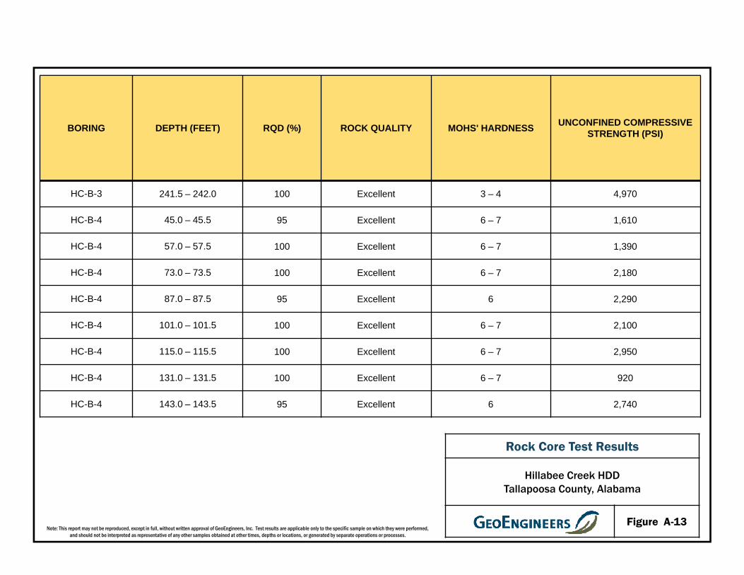
BORING DEPTH (FEET) RQD (%) ROCK QUALITY MOHS' HARDNESS UNCONFINED COMPRESSIVE STRENGTH (PSI)
HC-B-3 241.5 – 242.0 100 Excellent 3 – 4 4,970
HC-B-4 45.0 – 45.5 95 Excellent 6 – 7 1,610
HC-B-4 57.0 – 57.5 100 Excellent 6 – 7 1,390
HC-B-4 73.0 – 73.5 100 Excellent 6 – 7 2,180
HC-B-4 87.0 – 87.5 95 Excellent 6 2,290
HC-B-4 101.0 – 101.5 100 Excellent 6 – 7 2,100
HC-B-4 115.0 – 115.5 100 Excellent 6 – 7 2,950
HC-B-4 131.0 – 131.5 100 Excellent 6 – 7 920
HC-B-4 143.0 – 143.5 95 Excellent 6 2,740
Rock Core Test Results
Hillabee Creek HDD Tallapoosa County, Alabama
Figure A-13Note: This report may not be reproduced, except in full, without written approval of GeoEngineers, Inc. Test results are applicable only to the specific sample on which they were performed,
and should not be interpreted as representative of any other samples obtained at other times, depths or locations, or generated by separate operations or processes.
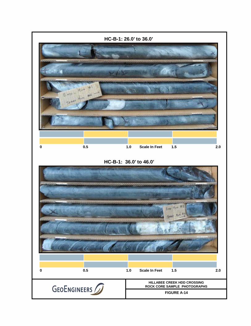
FIGURE A-14
HC-B-1: 26.0’ to 36.0’
0 0.5 1.0 Scale In Feet 1.5 2.0
0 0.5 1.0 Scale In Feet 1.5 2.0
HILLABEE CREEK HDD CROSSING ROCK CORE SAMPLE PHOTOGRAPHS
HC-B-1: 36.0’ to 46.0’

FIGURE A-15
HC-B-1: 46.0’ to 56.0’
0 0.5 1.0 Scale In Feet 1.5 2.0
0 0.5 1.0 Scale In Feet 1.5 2.0
HILLABEE CREEK HDD CROSSING ROCK CORE SAMPLE PHOTOGRAPHS
HC-B-1: 56.0’ to 66.0’

FIGURE A-16
HC-B-1: 66.0’ to 76.0’
0 0.5 1.0 Scale In Feet 1.5 2.0
0 0.5 1.0 Scale In Feet 1.5 2.0
HILLABEE CREEK HDD CROSSING ROCK CORE SAMPLE PHOTOGRAPHS
HC-B-1: 76.0’ to 86.0’

FIGURE A-17
HC-B-1: 86.0’ to 96.0’
0 0.5 1.0 Scale In Feet 1.5 2.0
0 0.5 1.0 Scale In Feet 1.5 2.0
HILLABEE CREEK HDD CROSSING ROCK CORE SAMPLE PHOTOGRAPHS
HC-B-1: 96.0’ to 106.0’

FIGURE A-18
HC-B-1: 106.0’ to 115.0’
0 0.5 1.0 Scale In Feet 1.5 2.0
0 0.5 1.0 Scale In Feet 1.5 2.0
HILLABEE CREEK HDD CROSSING ROCK CORE SAMPLE PHOTOGRAPHS
HC-B-2: 19.8’ to 29.5’
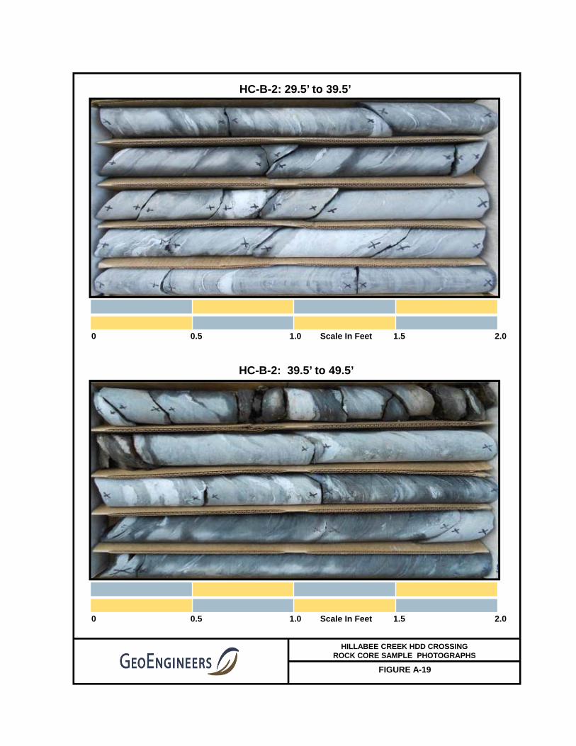
FIGURE A-19
HC-B-2: 29.5’ to 39.5’
0 0.5 1.0 Scale In Feet 1.5 2.0
0 0.5 1.0 Scale In Feet 1.5 2.0
HILLABEE CREEK HDD CROSSING ROCK CORE SAMPLE PHOTOGRAPHS
HC-B-2: 39.5’ to 49.5’

FIGURE A-20
HC-B-2: 49.5’ to 59.5’
0 0.5 1.0 Scale In Feet 1.5 2.0
0 0.5 1.0 Scale In Feet 1.5 2.0
HILLABEE CREEK HDD CROSSING ROCK CORE SAMPLE PHOTOGRAPHS
HC-B-2: 59.5’ to 69.5’

FIGURE A-21
HC-B-2: 69.5’ to 79.5’
0 0.5 1.0 Scale In Feet 1.5 2.0
0 0.5 1.0 Scale In Feet 1.5 2.0
HILLABEE CREEK HDD CROSSING ROCK CORE SAMPLE PHOTOGRAPHS
HC-B-2: 79.5’ to 89.5’

FIGURE A-22
HC-B-2: 89.5’ to 99.5’
0 0.5 1.0 Scale In Feet 1.5 2.0
0 0.5 1.0 Scale In Feet 1.5 2.0
HILLABEE CREEK HDD CROSSING ROCK CORE SAMPLE PHOTOGRAPHS
HC-B-2: 99.5’ to 109.5’

FIGURE A-23
HC-B-2: 109.5’ to 119.5’
0 0.5 1.0 Scale In Feet 1.5 2.0
0 0.5 1.0 Scale In Feet 1.5 2.0
HILLABEE CREEK HDD CROSSING ROCK CORE SAMPLE PHOTOGRAPHS
HC-B-2: 119.5’ to 129.5’

FIGURE A-24
HC-B-2: 129.5’ to 139.5’
0 0.5 1.0 Scale In Feet 1.5 2.0
0 0.5 1.0 Scale In Feet 1.5 2.0
HILLABEE CREEK HDD CROSSING ROCK CORE SAMPLE PHOTOGRAPHS
HC-B-2: 139.5’ to 149.5’

FIGURE A-25
HC-B-2: 149.5’ to 159.5’
0 0.5 1.0 Scale In Feet 1.5 2.0
0 0.5 1.0 Scale In Feet 1.5 2.0
HILLABEE CREEK HDD CROSSING ROCK CORE SAMPLE PHOTOGRAPHS
HC-B-2: 159.5’ to 169.5’
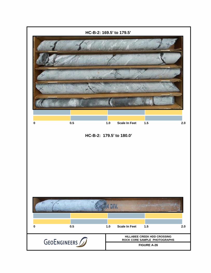
FIGURE A-26
HC-B-2: 169.5’ to 179.5’
0 0.5 1.0 Scale In Feet 1.5 2.0
0 0.5 1.0 Scale In Feet 1.5 2.0
HILLABEE CREEK HDD CROSSING ROCK CORE SAMPLE PHOTOGRAPHS
HC-B-2: 179.5’ to 180.0’
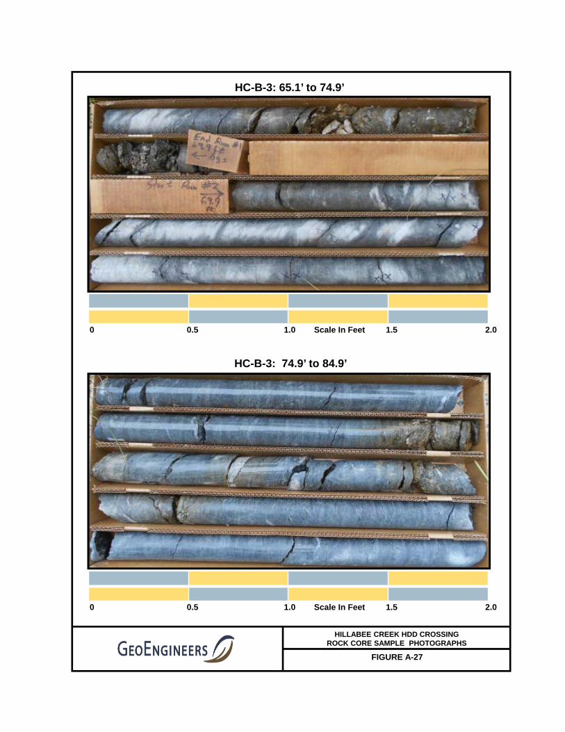
FIGURE A-27
HC-B-3: 65.1’ to 74.9’
0 0.5 1.0 Scale In Feet 1.5 2.0
0 0.5 1.0 Scale In Feet 1.5 2.0
HILLABEE CREEK HDD CROSSING ROCK CORE SAMPLE PHOTOGRAPHS
HC-B-3: 74.9’ to 84.9’

FIGURE A-28
HC-B-3: 84.9’ to 94.9’
0 0.5 1.0 Scale In Feet 1.5 2.0
0 0.5 1.0 Scale In Feet 1.5 2.0
HILLABEE CREEK HDD CROSSING ROCK CORE SAMPLE PHOTOGRAPHS
HC-B-3: 94.9’ to 104.9’

FIGURE A-29
HC-B-3: 104.9’ to 114.9’
0 0.5 1.0 Scale In Feet 1.5 2.0
0 0.5 1.0 Scale In Feet 1.5 2.0
HILLABEE CREEK HDD CROSSING ROCK CORE SAMPLE PHOTOGRAPHS
HC-B-3: 114.9’ to 124.9’

FIGURE A-30
HC-B-3: 124.9’ to 134.9’
0 0.5 1.0 Scale In Feet 1.5 2.0
0 0.5 1.0 Scale In Feet 1.5 2.0
HILLABEE CREEK HDD CROSSING ROCK CORE SAMPLE PHOTOGRAPHS
HC-B-3: 134.9’ to 144.9’
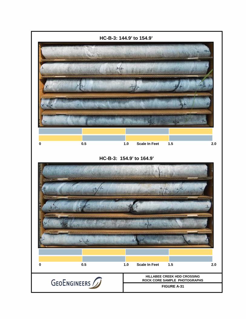
FIGURE A-31
HC-B-3: 144.9’ to 154.9’
0 0.5 1.0 Scale In Feet 1.5 2.0
0 0.5 1.0 Scale In Feet 1.5 2.0
HILLABEE CREEK HDD CROSSING ROCK CORE SAMPLE PHOTOGRAPHS
HC-B-3: 154.9’ to 164.9’

FIGURE A-32
HC-B-3: 164.9’ to 174.9’
0 0.5 1.0 Scale In Feet 1.5 2.0
0 0.5 1.0 Scale In Feet 1.5 2.0
HILLABEE CREEK HDD CROSSING ROCK CORE SAMPLE PHOTOGRAPHS
HC-B-3: 174.9’ to 184.9’

FIGURE A-33
HC-B-3: 184.9’ to 194.9’
0 0.5 1.0 Scale In Feet 1.5 2.0
0 0.5 1.0 Scale In Feet 1.5 2.0
HILLABEE CREEK HDD CROSSING ROCK CORE SAMPLE PHOTOGRAPHS
HC-B-3: 194.9’ to 204.9’
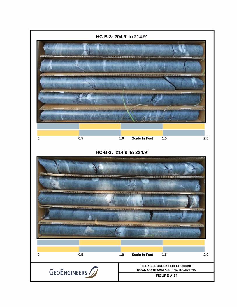
FIGURE A-34
HC-B-3: 204.9’ to 214.9’
0 0.5 1.0 Scale In Feet 1.5 2.0
0 0.5 1.0 Scale In Feet 1.5 2.0
HILLABEE CREEK HDD CROSSING ROCK CORE SAMPLE PHOTOGRAPHS
HC-B-3: 214.9’ to 224.9’

FIGURE A-35
HC-B-3: 224.9’ to 234.9’
0 0.5 1.0 Scale In Feet 1.5 2.0
0 0.5 1.0 Scale In Feet 1.5 2.0
HILLABEE CREEK HDD CROSSING ROCK CORE SAMPLE PHOTOGRAPHS
HC-B-3: 234.9’ to 245.0’

FIGURE A-36
HC-B-4: 35.2’ to 45.2’
HILLABEE CREEK HDD CROSSING ROCK CORE SAMPLE PHOTOGRAPHS
HC-B-4: 45.2’ to 55.2’

FIGURE A-37
HC-B-4: 55.2’ to 65.2’
HILLABEE CREEK HDD CROSSING ROCK CORE SAMPLE PHOTOGRAPHS
HC-B-4: 65.2’ to 75.2’

FIGURE A-38
HC-B-4: 75.2’ to 85.2’
HILLABEE CREEK HDD CROSSING ROCK CORE SAMPLE PHOTOGRAPHS
HC-B-4: 85.2’ to 95.2’
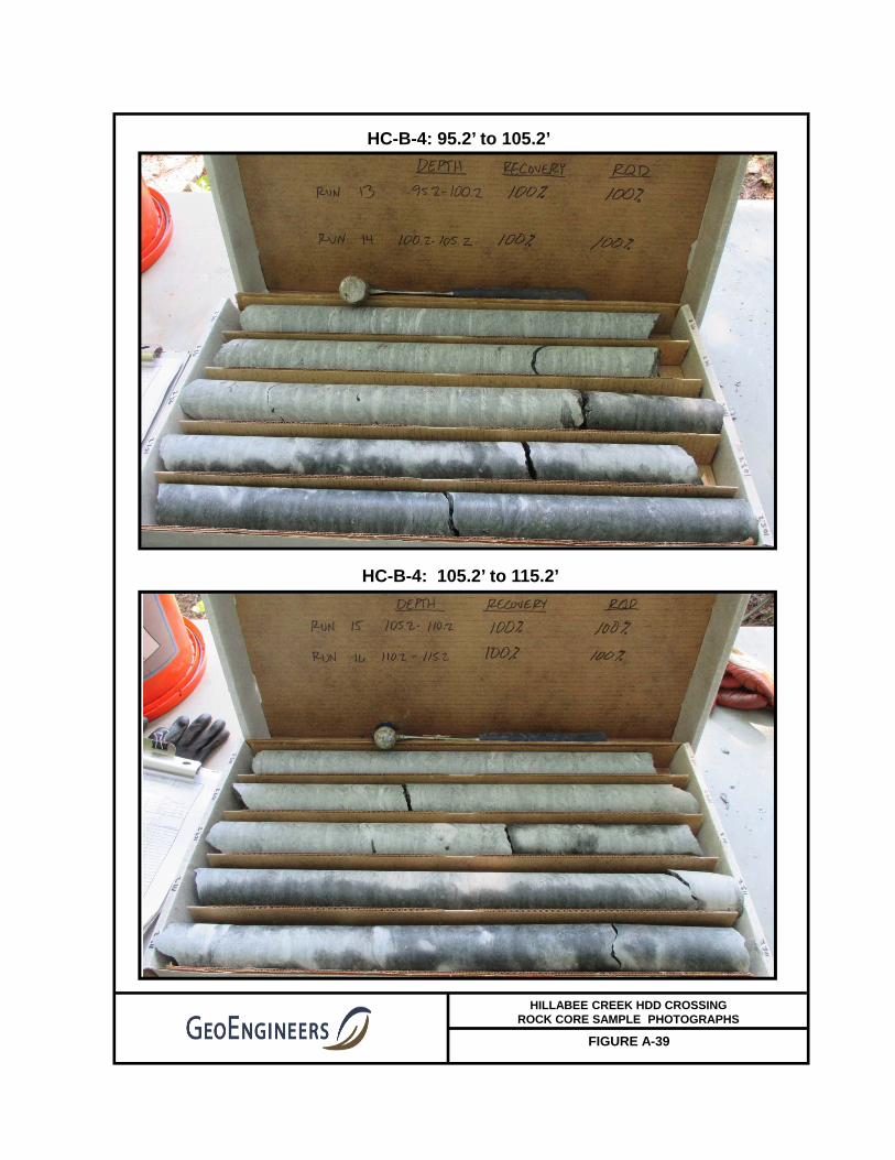
FIGURE A-39
HC-B-4: 95.2’ to 105.2’
HILLABEE CREEK HDD CROSSING ROCK CORE SAMPLE PHOTOGRAPHS
HC-B-4: 105.2’ to 115.2’
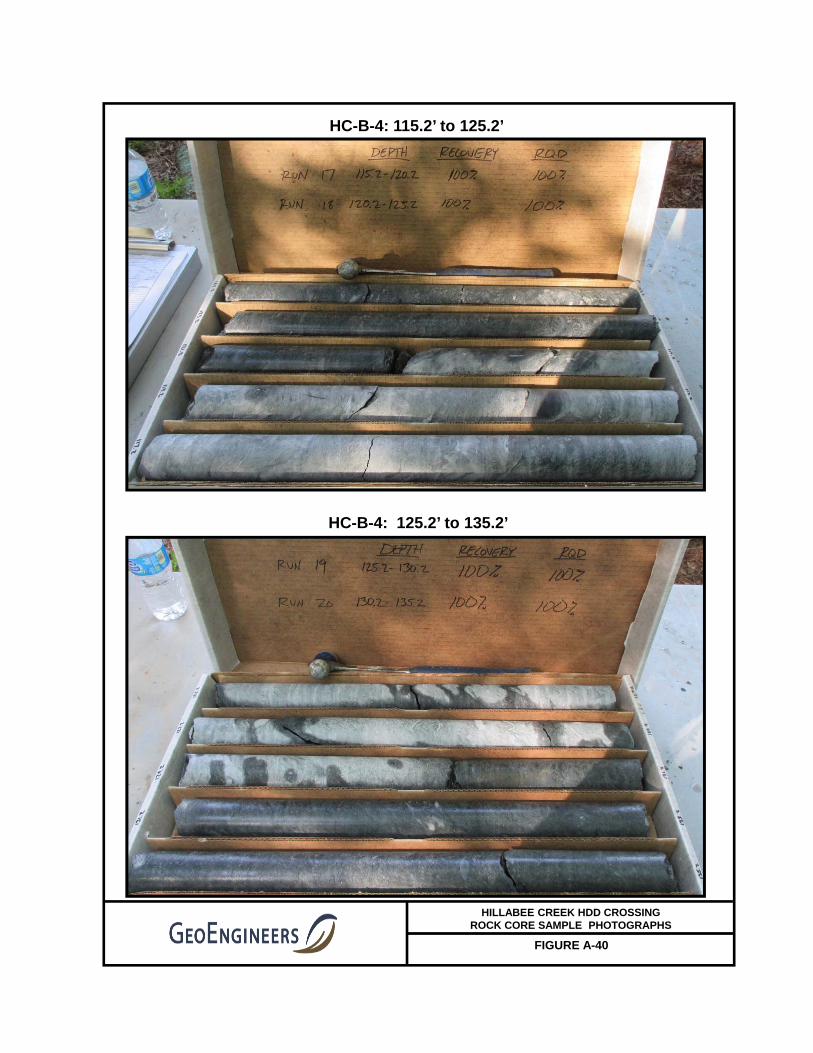
FIGURE A-40
HC-B-4: 115.2’ to 125.2’
HILLABEE CREEK HDD CROSSING ROCK CORE SAMPLE PHOTOGRAPHS
HC-B-4: 125.2’ to 135.2’
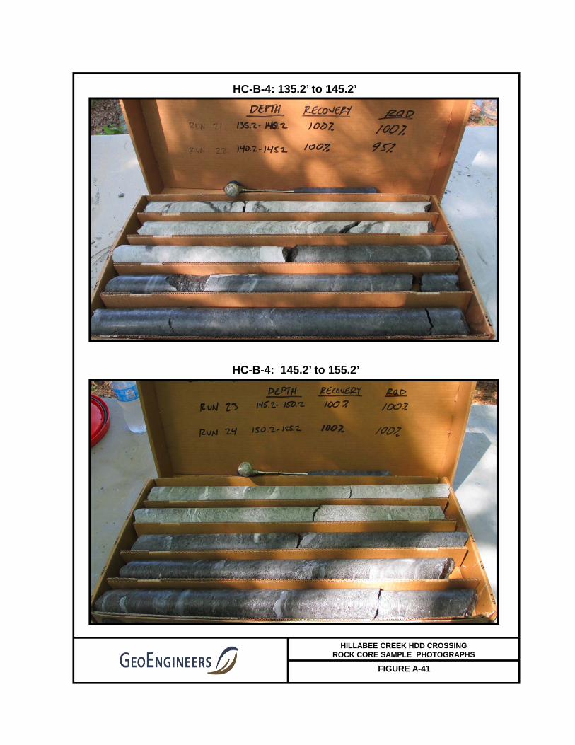
FIGURE A-41
HC-B-4: 135.2’ to 145.2’
HILLABEE CREEK HDD CROSSING ROCK CORE SAMPLE PHOTOGRAPHS
HC-B-4: 145.2’ to 155.2’

FIGURE A-42
HC-B-4: 155.2’ to 160.0’
HILLABEE CREEK HDD CROSSING ROCK CORE SAMPLE PHOTOGRAPHS
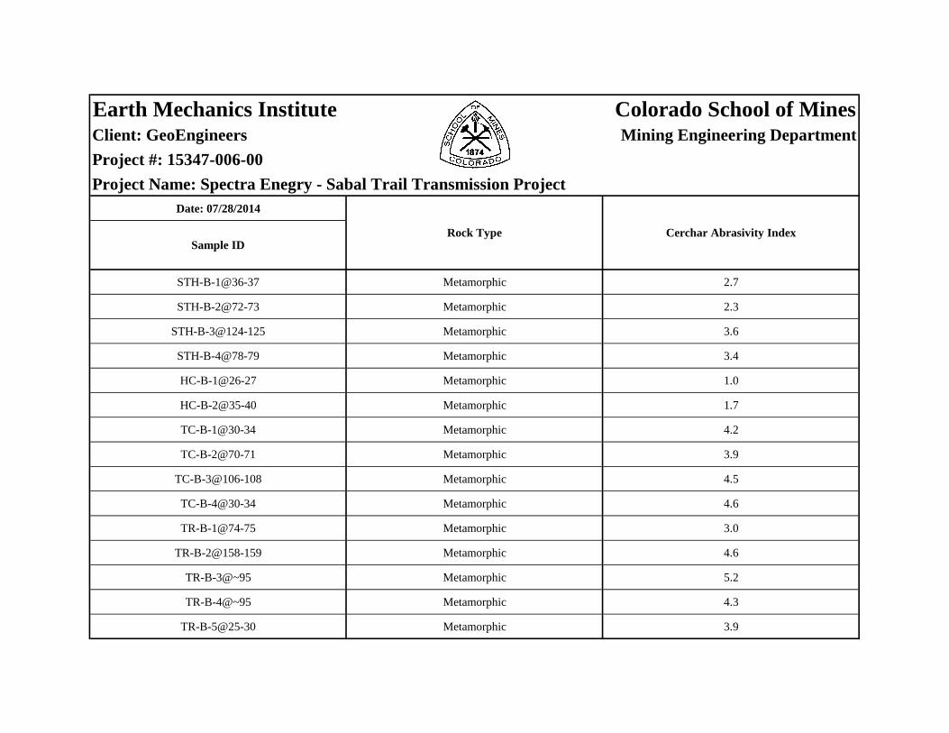
Earth Mechanics Institute Colorado School of MinesClient: GeoEngineers Mining Engineering Department
Project #: 15347-006-00
Project Name: Spectra Enegry - Sabal Trail Transmission ProjectDate: 07/28/2014
STH-B-1@36-37 Metamorphic 2.7
STH-B-2@72-73 Metamorphic 2.3
STH-B-3@124-125 Metamorphic 3.6
STH-B-4@78-79 Metamorphic 3.4
HC-B-1@26-27 Metamorphic 1.0
HC-B-2@35-40 Metamorphic 1.7
TC-B-1@30-34 Metamorphic 4.2
TC-B-2@70-71 Metamorphic 3.9
TC-B-3@106-108 Metamorphic 4.5
TC-B-4@30-34 Metamorphic 4.6
TR-B-1@74-75 Metamorphic 3.0
TR-B-2@158-159 Metamorphic 4.6
TR-B-3@~95 Metamorphic 5.2
TR-B-4@~95 Metamorphic 4.3
TR-B-5@25-30 Metamorphic 3.9
Sample IDRock Type Cerchar Abrasivity Index
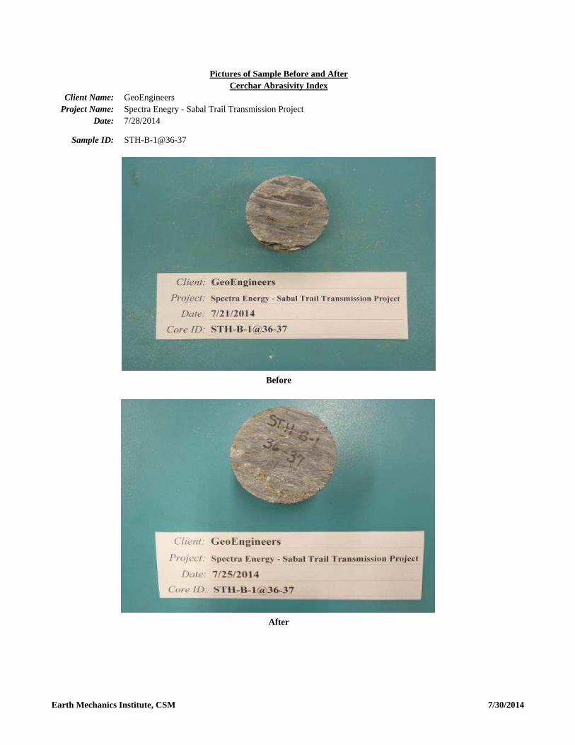
After
Pictures of Sample Before and AfterCerchar Abrasivity Index
Client Name: GeoEngineersProject Name: Spectra Enegry - Sabal Trail Transmission Project
Date: 7/28/2014
Sample ID: STH-B-1@36-37
Before
Earth Mechanics Institute, CSM 7/30/2014

After
Pictures of Sample Before and AfterCerchar Abrasivity Index
Client Name: GeoEngineersProject Name: Spectra Enegry - Sabal Trail Transmission Project
Date: 7/28/2014
Sample ID: STH-B-2@72-73
Before
Earth Mechanics Institute, CSM 7/30/2014

After
Pictures of Sample Before and AfterCerchar Abrasivity Index
Client Name: GeoEngineersProject Name: Spectra Enegry - Sabal Trail Transmission Project
Date: 7/28/2014
Sample ID: STH-B-3@124-125
Before
Earth Mechanics Institute, CSM 7/30/2014

After
Pictures of Sample Before and AfterCerchar Abrasivity Index
Client Name: GeoEngineersProject Name: Spectra Enegry - Sabal Trail Transmission Project
Date: 7/28/2014
Sample ID: STH-B-4@78-79
Before
Earth Mechanics Institute, CSM 7/30/2014

After
Pictures of Sample Before and AfterCerchar Abrasivity Index
Client Name: GeoEngineersProject Name: Spectra Enegry - Sabal Trail Transmission Project
Date: 7/28/2014
Sample ID: HC-B-1@26-27
Before
Earth Mechanics Institute, CSM 7/30/2014
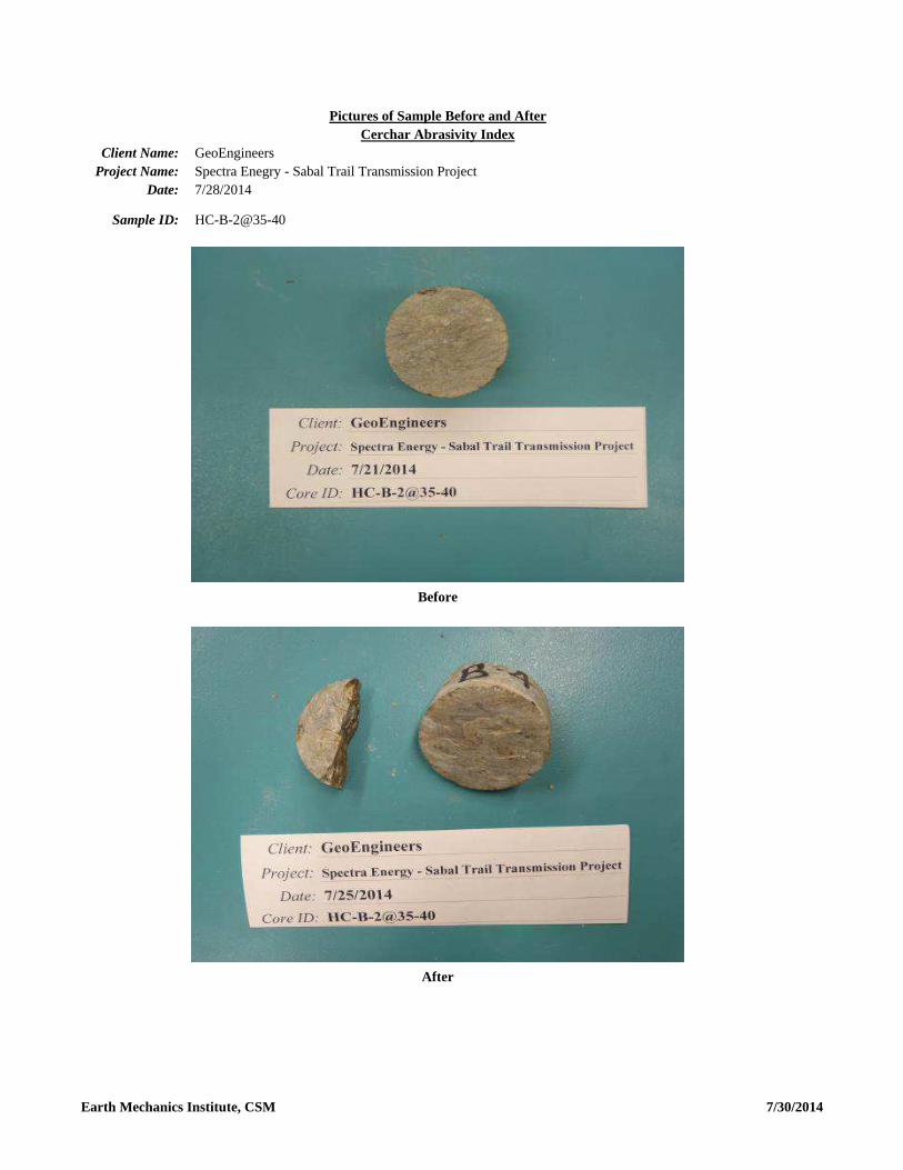
After
Pictures of Sample Before and AfterCerchar Abrasivity Index
Client Name: GeoEngineersProject Name: Spectra Enegry - Sabal Trail Transmission Project
Date: 7/28/2014
Sample ID: HC-B-2@35-40
Before
Earth Mechanics Institute, CSM 7/30/2014
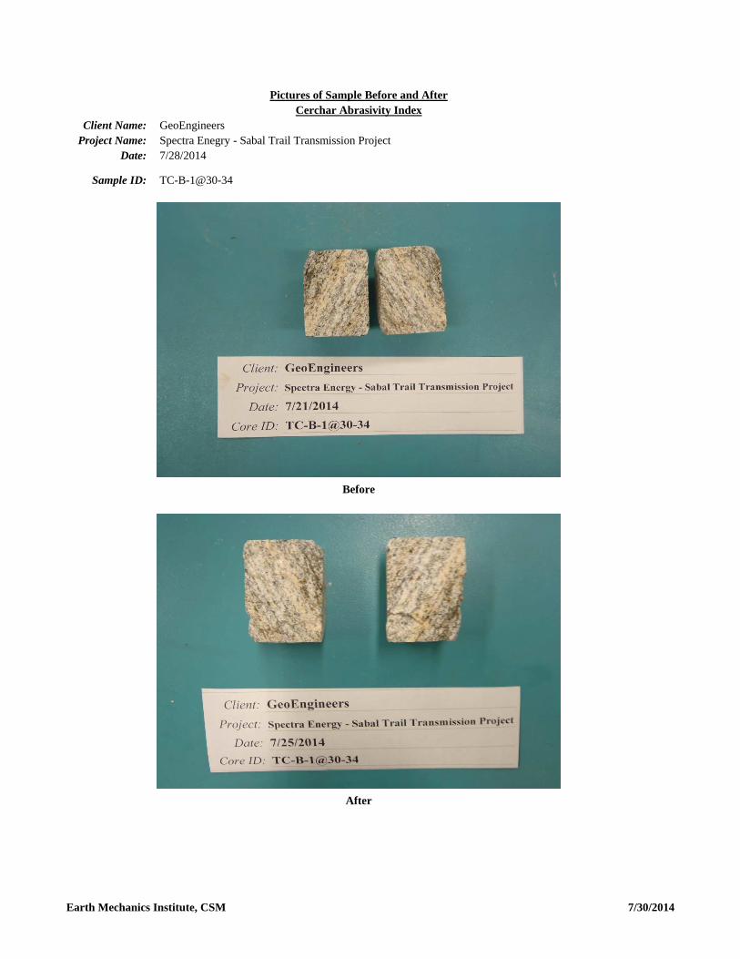
After
Pictures of Sample Before and AfterCerchar Abrasivity Index
Client Name: GeoEngineersProject Name: Spectra Enegry - Sabal Trail Transmission Project
Date: 7/28/2014
Sample ID: TC-B-1@30-34
Before
Earth Mechanics Institute, CSM 7/30/2014

After
Pictures of Sample Before and AfterCerchar Abrasivity Index
Client Name: GeoEngineersProject Name: Spectra Enegry - Sabal Trail Transmission Project
Date: 7/28/2014
Sample ID: TC-B-2@70-71
Before
Earth Mechanics Institute, CSM 7/30/2014

After
Pictures of Sample Before and AfterCerchar Abrasivity Index
Client Name: GeoEngineersProject Name: Spectra Enegry - Sabal Trail Transmission Project
Date: 7/28/2014
Sample ID: TC-B-3@106-108
Before
Earth Mechanics Institute, CSM 7/30/2014
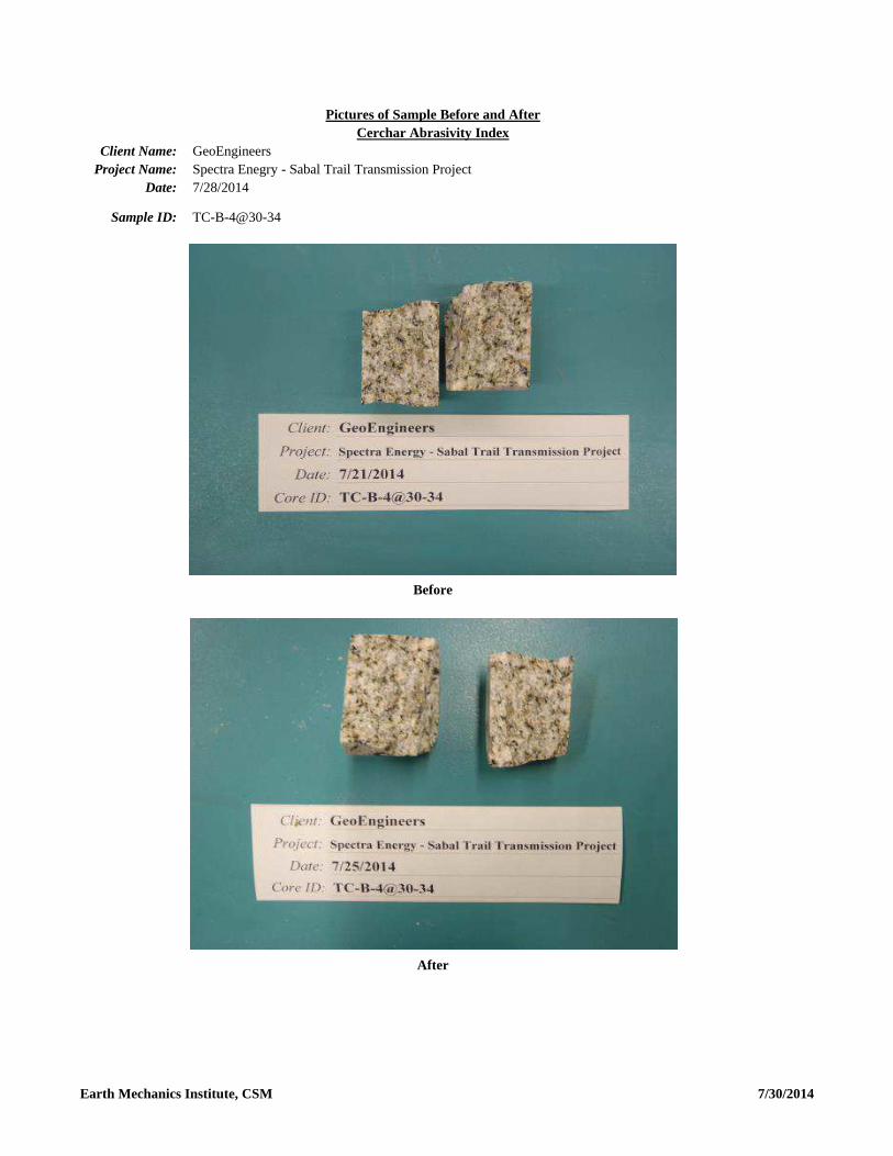
After
Pictures of Sample Before and AfterCerchar Abrasivity Index
Client Name: GeoEngineersProject Name: Spectra Enegry - Sabal Trail Transmission Project
Date: 7/28/2014
Sample ID: TC-B-4@30-34
Before
Earth Mechanics Institute, CSM 7/30/2014
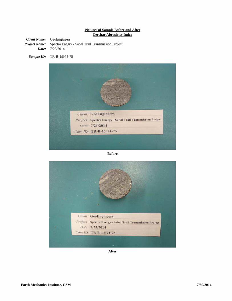
After
Pictures of Sample Before and AfterCerchar Abrasivity Index
Client Name: GeoEngineersProject Name: Spectra Enegry - Sabal Trail Transmission Project
Date: 7/28/2014
Sample ID: TR-B-1@74-75
Before
Earth Mechanics Institute, CSM 7/30/2014

After
Pictures of Sample Before and AfterCerchar Abrasivity Index
Client Name: GeoEngineersProject Name: Spectra Enegry - Sabal Trail Transmission Project
Date: 7/28/2014
Sample ID: TR-B-2@158-159
Before
Earth Mechanics Institute, CSM 7/30/2014
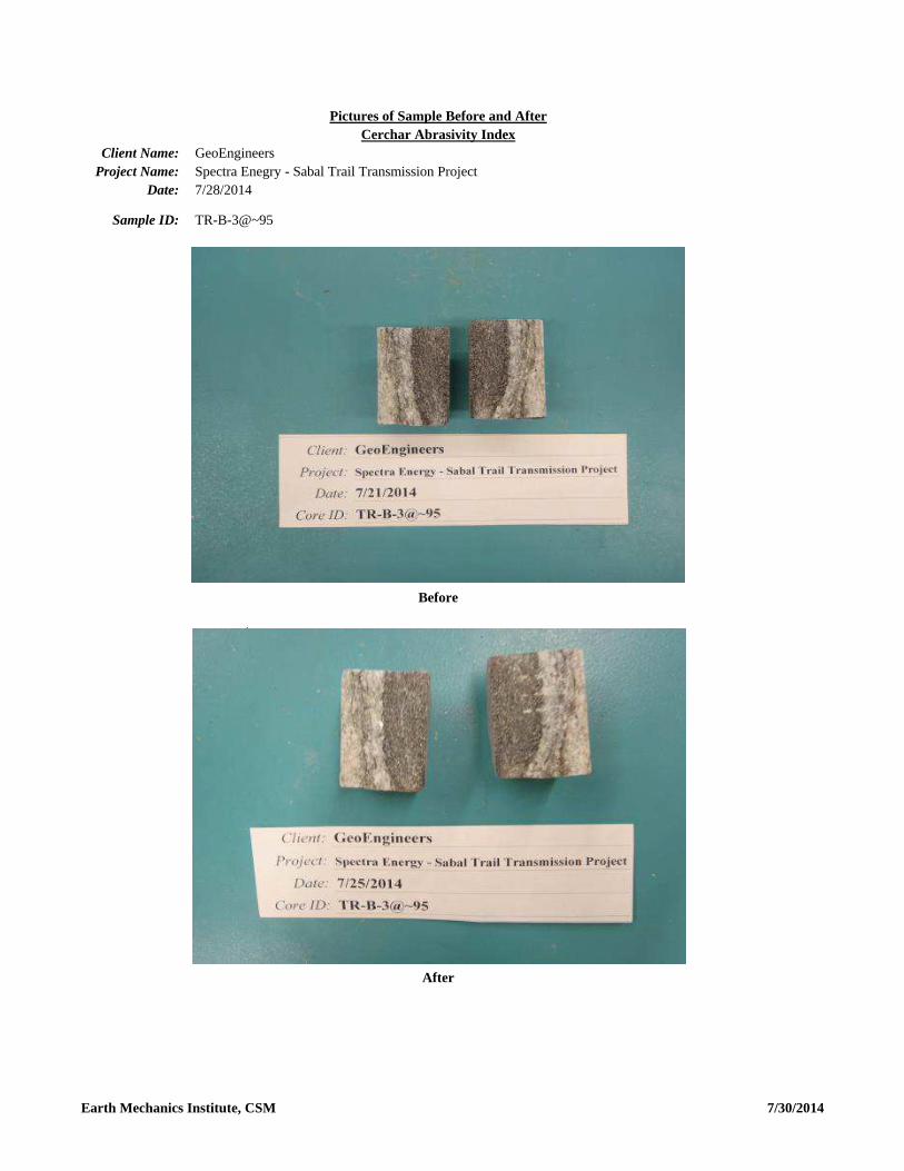
After
Pictures of Sample Before and AfterCerchar Abrasivity Index
Client Name: GeoEngineersProject Name: Spectra Enegry - Sabal Trail Transmission Project
Date: 7/28/2014
Sample ID: TR-B-3@~95
Before
Earth Mechanics Institute, CSM 7/30/2014

After
Pictures of Sample Before and AfterCerchar Abrasivity Index
Client Name: GeoEngineersProject Name: Spectra Enegry - Sabal Trail Transmission Project
Date: 7/28/2014
Sample ID: TR-B-4@~95
Before
Earth Mechanics Institute, CSM 7/30/2014

After
Pictures of Sample Before and AfterCerchar Abrasivity Index
GeoEngineersSpectra Enegry - Sabal Trail Transmission Project7/28/2014
TR-B-5@25-30
Client Name:Project Name:
Date:
Sample ID:
Before
Earth Mechanics Institute, CSM 7/30/2014

Earth Mechanics Institute Colorado School of MinesClient: GeoEngineers Mining Engineering Department
Location: N/A
Project Name: N/ADate: 08/13/2014
Sample
ID
HC-B-2@121 Metamorphic 1.9
HC-B-3@117 Metamorphic 2.7
Rock Type Cerchar Abrasivity Index

Client Name:Project Name:
Date:
Sample ID:
Before
After
Pictures of Sample Before and AfterCerchar Abrasivity Index
GeoEngineersN/A8/12/2014
HC-B-2@121
Earth Mechanics Institute, CSM 8/14/2014

After
Pictures of Sample Before and AfterCerchar Abrasivity Index
Client Name: GeoEngineersProject Name: N/A
Date: 8/12/2014
Sample ID: HC-B-3@117
Before
Earth Mechanics Institute, CSM 8/14/2014
APPENDIX B Report Limitations and Guidelines for Use

November 17, 2014| Page B-1 File No. 15347-006-00
APPENDIX B
REPORT LIMITATIONS AND GUIDELINES FOR USE1
This appendix provides information to help you manage your risks with respect to the use of this report.
Geotechnical and Environmental Services Are Performed for Specific Purposes, Persons and
Projects
This report has been prepared for the exclusive use of Gulf Interstate Engineering, Sabal Trail
Transmission and their authorized agents. This report is not intended for use by others, and the
information contained herein is not applicable to other sites.
GeoEngineers structures our services to meet the specific needs of our clients. For example, a
geotechnical or geologic study conducted for a civil engineer or architect may not fulfill the needs of a
construction contractor or even another civil engineer or architect that are involved in the same project.
Similarly, an environmental assessment study conducted for a property owner may not fulfill the needs of
a prospective purchaser of the same property. Because each study is unique, each report is unique,
prepared solely for the specific client and project site. Our report is prepared for the exclusive use of our
Client. No other party may rely on the product of our services unless we agree in advance to such
reliance in writing. This is to provide our firm with reasonable protection against open-ended liability
claims by third parties with whom there would otherwise be no contractual limits to their actions. Within
the limitations of scope, schedule and budget, our services have been executed in accordance with our
Agreement with the Client and generally accepted geotechnical practices in this area at the time this
report was prepared. This report should not be applied for any purpose or project except the one
originally contemplated.
A Geotechnical Engineering or Environmental Report Is Based on a Unique Set of
Project-Specific Factors
This report has been prepared for the proposed Hillabee Creek HDD located in Tallapoosa County,
Alabama. GeoEngineers considered a number of unique, project-specific factors when establishing the
scope of services for this project and report. Unless GeoEngineers specifically indicates otherwise, do not
rely on this report if it was:
■ not prepared for you,
■ not prepared for your project,
■ not prepared for the specific site explored, or
■ completed before important project changes were made.
For example, changes that can affect the applicability of this report include those that affect:
■ the function of the proposed structure;
1 Developed based on material provided by ASFE/The Best People on Earth, Professional Firms Practicing in the
Geosciences; www.asfe.org.

November 17, 2014| Page B-2 File NO. 15347-006-00
■ elevation, configuration, location, orientation or weight of the proposed structure;
■ composition of the design team; or
■ project ownership.
If important changes are made after the date of this report, GeoEngineers should be given the opportunity
to review our interpretations and recommendations and provide written modifications or confirmation, as
appropriate.
Subsurface Conditions Can Change
This report is based on conditions that existed at the time the study was performed. The findings and
conclusions of this report may be affected by the passage of time, by manmade events such as
construction on or adjacent to the site, by new releases of hazardous substances, or by natural events
such as floods, earthquakes, slope instability or groundwater fluctuations. Always contact GeoEngineers
before applying a report to determine if it remains applicable.
Most Geotechnical and Environmental Findings Are Professional Opinions
Our interpretations of subsurface conditions are based on field observations and laboratory test results
from widely spaced sampling locations at the site. Site exploration identifies subsurface conditions only
at those points where subsurface tests are conducted or samples are taken. GeoEngineers reviewed
field and laboratory data and then applied our professional judgment to render an opinion about
subsurface conditions throughout the site. Actual subsurface conditions may differ, sometimes
significantly, from those indicated in this report. Our report, conclusions and interpretations should not
be construed as a warranty of the subsurface conditions.
Do Not Redraw the Exploration Logs
Geotechnical engineers and geologists prepare final boring and testing logs based upon their
interpretation of field logs and laboratory data. To prevent errors or omissions, the logs included in a
geotechnical engineering or geologic report should never be redrawn for inclusion in architectural or other
design drawings. Only photographic or electronic reproduction is acceptable, but recognize that
separating logs from the report can elevate risk.
Contractors Are Responsible for Site Safety on Their Own Construction Projects
Our geotechnical recommendations are not intended to direct the contractor’s procedures, methods,
schedule or management of the work site. The contractor is solely responsible for job site safety and for
managing construction operations to minimize risks to on-site personnel and to adjacent properties.
Read These Provisions Closely
Some clients, design professionals and contractors may not recognize that the geoscience practices
(geotechnical engineering or geology) are far less exact than other engineering and natural science
disciplines. This lack of understanding can create unrealistic expectations that could lead to
disappointments, claims and disputes. GeoEngineers includes these explanatory “limitations” provisions
in our reports to help reduce such risks. Please confer with GeoEngineers if you are unclear how these
“Report Limitations and Guidelines for Use” apply to your project or site.

Have we delivered World Class Client Service?
Please let us know by visiting www.geoengineers.com/feedback.