geotechnical design report proposed culvert...
TRANSCRIPT
FUGRO CONSULTANTS, INC.
GEOTECHNICAL DESIGN REPORT PROPOSED CULVERT CROSSING
OVER COYOTE CREEK DONLON ROAD REALIGNMENT PROJECT VENTURA COUNTY (SOMIS), CALIFORNIA
Prepared for: COUNTY OF VENTURA
December 2014 Fugro Project No. 04.62140103
FUGRO CONSULTANTS, INC.
4820 McGrath Street, Suite 100Ventura, California 93003-7778
Tel: (805) 650-7000Fax: (805) 650-7010
A member of the Fugro group of companies with offices throughout the world.
December 8, 2014 Project No. 04.62140103
County of Ventura Public Works 800 South Victoria Avenue Ventura, California 93009
Attention: Ms. Alison Sweet
Subject: Geotechnical Design Report, Proposed Culvert Crossing over Coyote Creek, Donlon Road Realignment Project, Ventura County, California
Dear Ms. Sweet:
Fugro Consultants, Inc. (Fugro) appreciates the opportunity to prepare this Geotechnical Design Report to support the Donlon Road Realignment Project in Ventura County, California. This report was prepared according to, and authorized by, contract work order PW15-036 issued on August 25, 2014 under our annual consulting services agreement with the Ventura County Public Works Agency (County).
Please contact the undersigned if you have any questions or we can be of additional service.
Sincerely,
FUGRO CONSULTANTS, INC.
Justin R. Martos, E.I.T. Loree A. Berry, P.E. Senior Staff Engineer Senior Project Engineer
Reviewed by:
Gregory S. Denlinger, G.E. Principal Geotechnical Engineer
Copies Submitted: (4) and PDF Addressee
County of Ventura December 8, 2014 (Project No. 04.62140103)
CONTENTS
Page
1.0 INTRODUCTION ....................................................................................................... 1 1.1 Project Description .......................................................................................... 1 1.2 Purpose ........................................................................................................... 1 1.3 General Conditions .......................................................................................... 1
2.0 WORK PERFORMED ................................................................................................ 2 2.1 Scope of Services ........................................................................................... 2 2.2 Field Exploration .............................................................................................. 3 2.3 Laboratory Testing .......................................................................................... 3
3.0 FINDINGS .................................................................................................................. 3 3.1 Site Conditions ................................................................................................ 3 3.2 Geologic Setting .............................................................................................. 3 3.3 Subsurface Conditions .................................................................................... 4
3.3.1 Artificial Fill (af) ....................................................................................... 4 3.3.2 Alluvium (Qal) ......................................................................................... 4 3.3.3 Groundwater Conditions ......................................................................... 4
4.0 SEISMICITY AND OTHER GEOHAZARDS .............................................................. 5 4.1 Local Faults ..................................................................................................... 5 4.2 Surface Fault Rupture ..................................................................................... 5 4.3 Strong Ground Motion ..................................................................................... 6 4.4 2013 CBC Design Criteria ............................................................................... 6 4.5 Liquefaction and Dry Seismic Settlement ........................................................ 7 4.6 Slope Stability .................................................................................................. 8
5.0 CONCLUSIONS AND RECOMMENDATIONS .......................................................... 8 5.1 Earthwork and Grading ................................................................................... 8 5.2 Clearing and Grubbing .................................................................................... 8 5.3 Overexcavation ............................................................................................... 8 5.4 Subgrade Preparation ..................................................................................... 9 5.5 Special Subgrade Stabilization Measures ....................................................... 9 5.6 Compacted Fill .............................................................................................. 10
5.6.1 On-Site Soil Materials ........................................................................... 10 5.6.2 Imported Borrow ................................................................................... 10 5.6.3 Structure Backfill ................................................................................... 10 5.6.4 Pipe Bedding and Pipe Zone Backfill .................................................... 11 5.6.5 Trench Backfill ...................................................................................... 11 5.6.6 Drainage Material ................................................................................. 11 5.6.7 Fill Placement and Compaction Requirements ..................................... 11
5.7 Construction Considerations ......................................................................... 12 5.7.1 Excavation Effort ................................................................................... 12 5.7.2 Temporary Excavations ........................................................................ 12
County of Ventura December 8, 2014 (Project No. 04.62140103)
6.0 CULVERT DESIGN ................................................................................................. 12 6.1 Grading Recommendations ........................................................................... 12
6.1.1 General ................................................................................................. 12 6.1.2 Groundwater and Dewatering ............................................................... 13
6.2 Allowable Bearing Pressure .......................................................................... 13 6.3 Static Settlement ........................................................................................... 13 6.4 Resistance to Lateral Loads .......................................................................... 13
6.4.1 Sliding Resistance ................................................................................ 13 6.4.2 Passive Resistance .............................................................................. 14
6.5 Lateral Earth Pressures ................................................................................. 14 6.5.1 General ................................................................................................. 14 6.5.2 Equivalent Fluid Weights ...................................................................... 14
7.0 REINFORCED CONCRETE BOX STORM DRAIN DESIGN ................................... 15 7.1.1 External Loads ...................................................................................... 15 7.1.2 Modulus of Soil Reaction ...................................................................... 15 7.1.3 Uplift Pressures .................................................................................... 15
8.0 SOIL CHEMISTRY AND CORROSION ................................................................... 16 8.1 Test Results .................................................................................................. 16 8.2 Corrosion ....................................................................................................... 16 8.3 Cement Type ................................................................................................. 16
9.0 CONTINUING SERVICES ....................................................................................... 17 9.1 Plan Review .................................................................................................. 17 9.2 Construction Monitoring ................................................................................ 17
10.0 REFERENCES ....................................................................................................... 18
County of Ventura December 8, 2014 (Project No. 04.62140103)
CONTENTS CONTINUED...
PLATES
Plate
Vicinity Map ......................................................................................................................... 1 Subsurface Exploration Location Plan ................................................................................ 2 Regional Geologic Map ....................................................................................................... 3 Subsurface Profile A-A’ ....................................................................................................... 4
APPENDICES
APPENDIX A LOG OF EXPLORATORY DRILL HOLES Key to Terms & Symbols Used on Logs ................................................................................. A-1 Log of Drill Holes ................................................................................................. A-2 through A-7
APPENDIX B LABORATORY TESTING Summary of Laboratory Test Results ..................................................................................... B-1 Grain Size Curves .................................................................................................................. B-2 Plasticity Chart ....................................................................................................................... B-3 Consolidation Test Results .............................................................................. B-4a through B-4b Direct Shear Test Results ....................................................................................................... B-5 Unconsolidated, Undrained Triaxial Test Results .................................................................. B-6 Compaction Curve .................................................................................................................. B-7
County of Ventura December 8, 2014 (Project No. 04.62140103)
1 O:\MANAGEMENT\04_2014\04_6214_0103_VC_DONLONROADCULVERT\06_REPORTS\04_6214_0103_RPT.DOC
1.0 INTRODUCTION
1.1 PROJECT DESCRIPTION
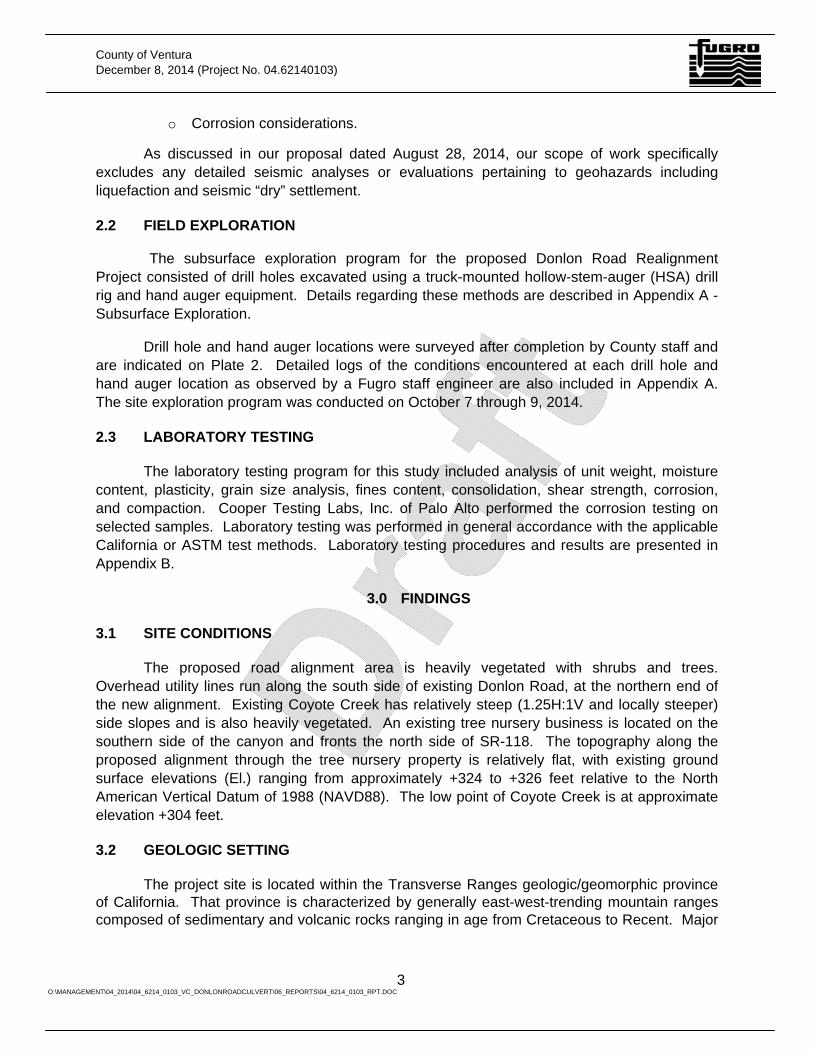
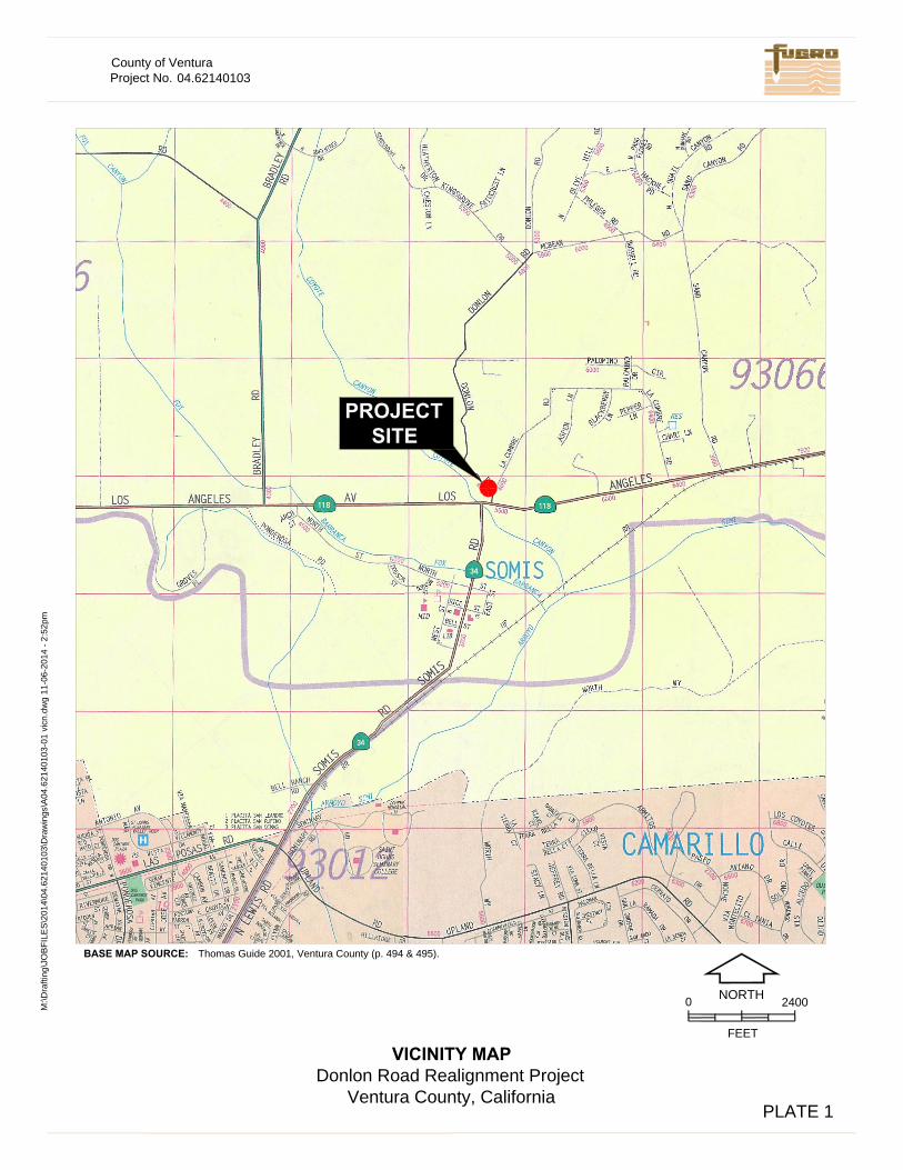
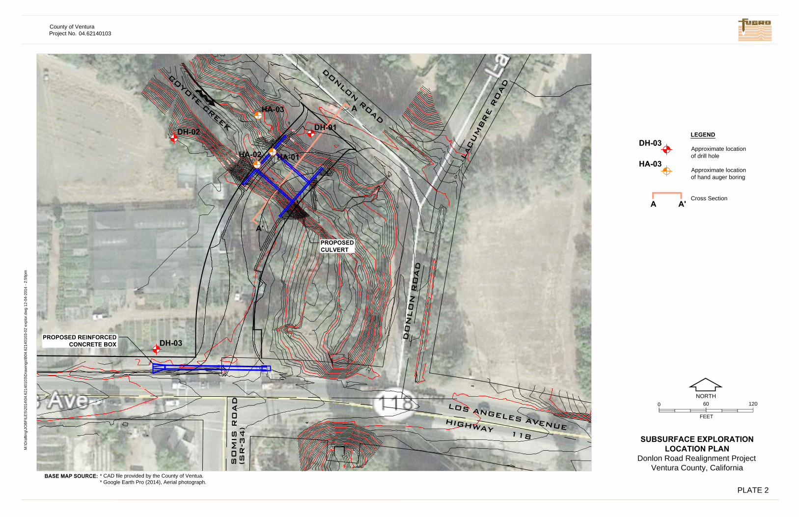
The proposed Donlon Road Realignment Project extends directly north of the intersection of Somis Road (State Route SR-34) and East Los Angeles Avenue (State Route SR-118) at the general location indicated on Plate 1 - Vicinity Map. The existing Donlon Road alignment runs parallel to the northeast side of Coyote creek and intersects SR-118 approximately 200 feet east of SR-34. In an effort to streamline traffic flow along that section of SR-118, the County has proposed to realign Donlon Road to extend due north of the SR-34 intersection. The proposed realignment involves a culvert crossing over Coyote Creek approximately 150 feet northwest of La Cumbre Road. The Right of Way (ROW) for the proposed realignment is shown on Plate 2 - Subsurface Exploration Location Plan.
It is our understanding that the County plans to use a large precast arch culvert, such as the CONTECH® CON/SPAN O-SeriesTM, to bridge a 30-foot span over Coyote Creek. The existing creekbed extends approximately 20 feet below the proposed road elevation and the culvert will therefore require headwalls on the order of about 20 feet and 24-foot-long wing wall segments angled at approximately 45 degrees from the headwalls.
The proposed project also includes construction of a 48-inch-wide by 36-inch-tall reinforced concrete box (RCB) storm drain running parallel to the northern shoulder of SR-118. The proposed storm drain segment is 125 lineal feet.
1.2 PURPOSE
The purpose of this geotechnical study was to evaluate the geotechnical conditions along the proposed culvert crossing and RCB storm drain and provide conclusions and recommendations to aid in the design and construction of those structures.
1.3 GENERAL CONDITIONS
Fugro prepared the conclusions, recommendations, and professional opinions of this report in accordance with the generally accepted geotechnical principles and practices at this time and location. This warranty is in lieu of all other warranties, either express or implied. This report was prepared for the exclusive use of the Ventura County Public Works Agency and their authorized agents only. It may not contain sufficient information for the purposes of other parties or other uses. If any changes are made in the project as described in this report, the conclusions and recommendations contained in this report should not be considered valid unless Fugro reviews the changes and modifies and approves, in writing, the conclusions and recommendations of this report. This report and the drawings contained in this report are intended for design-input purposes; they are not intended to act as construction drawings or specifications.
The scope of services did not include any environmental assessments for the presence or absence of hazardous/toxic materials in the soil, surface water, groundwater, or atmosphere.
County of Ventura December 8, 2014 (Project No. 04.62140103)
2 O:\MANAGEMENT\04_2014\04_6214_0103_VC_DONLONROADCULVERT\06_REPORTS\04_6214_0103_RPT.DOC
Any statements or absence of statements in this report, or data presented herein regarding odors, unusual or suspicious items, or conditions observed, are strictly for descriptive purposes and are not intended to convey engineering judgment regarding potential hazardous/toxic assessment.
Soil deposits can vary in type, strength, and other geotechnical properties between points of observations and exploration. Additionally, groundwater and soil moisture conditions also can vary seasonally or for other reasons. Therefore, we do not and cannot have a complete knowledge of the subsurface conditions underlying the sites. The conclusions and recommendations presented in this report are based upon the findings at the points of exploration, and interpolation and extrapolation of information between and beyond the points of observation, and are subject to confirmation based on the conditions revealed by construction.
2.0 WORK PERFORMED
2.1 SCOPE OF SERVICES
The scope of this geotechnical study is outlined in our proposal dated August 28, 2014. The work performed for this study consisted of data review, subsurface exploration, laboratory testing, geotechnical evaluation, and reporting. Tasks performed for this study are described below.
• Reviewing selected published geologic maps and other geotechnical information relative to characterizing the geology and soil conditions in the project area;
• Executing a project-specific subsurface exploration and laboratory testing program;
• Characterizing the subsurface conditions based on the geotechnical data obtained from our work and data review, and;
• Preparing this geotechnical design report that includes the following:
o Factual data, including exploration logs and results of laboratory testing;
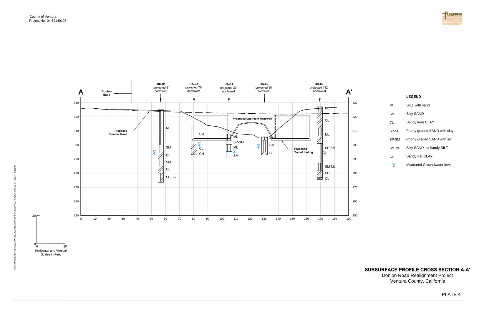
o Exploration location map and one subsurface profile across Coyote Creek at the crossing location;
o Summary of the soil and groundwater conditions encountered;
o General discussion of seismic setting and potential geohazards;
o Recommendations for shallow foundations, including allowable bearing pressure, resistance to lateral loads, and settlement;
o Lateral earth pressures;
o Earthwork and grading, which consists of remedial grading (overexcavation), fill selection, placement and compaction, and suitability of onsite soil for use as fill;
o Construction considerations including excavations, groundwater dewatering, and subgrade preparation and/or stabilization; and
County of Ventura December 8, 2014 (Project No. 04.62140103)
3 O:\MANAGEMENT\04_2014\04_6214_0103_VC_DONLONROADCULVERT\06_REPORTS\04_6214_0103_RPT.DOC
o Corrosion considerations.
As discussed in our proposal dated August 28, 2014, our scope of work specifically excludes any detailed seismic analyses or evaluations pertaining to geohazards including liquefaction and seismic “dry” settlement.
2.2 FIELD EXPLORATION
The subsurface exploration program for the proposed Donlon Road Realignment Project consisted of drill holes excavated using a truck-mounted hollow-stem-auger (HSA) drill rig and hand auger equipment. Details regarding these methods are described in Appendix A - Subsurface Exploration.
Drill hole and hand auger locations were surveyed after completion by County staff and are indicated on Plate 2. Detailed logs of the conditions encountered at each drill hole and hand auger location as observed by a Fugro staff engineer are also included in Appendix A. The site exploration program was conducted on October 7 through 9, 2014.
2.3 LABORATORY TESTING
The laboratory testing program for this study included analysis of unit weight, moisture content, plasticity, grain size analysis, fines content, consolidation, shear strength, corrosion, and compaction. Cooper Testing Labs, Inc. of Palo Alto performed the corrosion testing on selected samples. Laboratory testing was performed in general accordance with the applicable California or ASTM test methods. Laboratory testing procedures and results are presented in Appendix B.
3.0 FINDINGS
3.1 SITE CONDITIONS
The proposed road alignment area is heavily vegetated with shrubs and trees. Overhead utility lines run along the south side of existing Donlon Road, at the northern end of the new alignment. Existing Coyote Creek has relatively steep (1.25H:1V and locally steeper) side slopes and is also heavily vegetated. An existing tree nursery business is located on the southern side of the canyon and fronts the north side of SR-118. The topography along the proposed alignment through the tree nursery property is relatively flat, with existing ground surface elevations (El.) ranging from approximately +324 to +326 feet relative to the North American Vertical Datum of 1988 (NAVD88). The low point of Coyote Creek is at approximate elevation +304 feet.
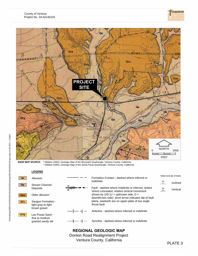
3.2 GEOLOGIC SETTING
The project site is located within the Transverse Ranges geologic/geomorphic province of California. That province is characterized by generally east-west-trending mountain ranges composed of sedimentary and volcanic rocks ranging in age from Cretaceous to Recent. Major
County of Ventura December 8, 2014 (Project No. 04.62140103)
4 O:\MANAGEMENT\04_2014\04_6214_0103_VC_DONLONROADCULVERT\06_REPORTS\04_6214_0103_RPT.DOC
east-west trending folds, reverse faults, and left-lateral strike-slip faults reflect regional north-south compression and are characteristic of the Transverse Ranges.
As mapped by Dibblee (1992a) and encountered during our subsurface exploration, earth materials exposed at the site consist of a mixture of fine- to coarse-grained alluvium deposits. Additionally, possible artificial fill materials associated with development of the nursery property and existing Donlon Road and SR-118 appear to be locally present.
3.3 SUBSURFACE CONDITIONS
The following subsections provide summaries of soil and groundwater conditions encountered during our study. Our interpretation of soil conditions presented herein is based on visual classification of samples obtained from our field exploration, the results of subsequent geotechnical laboratory testing, and our review of relevant geotechnical data. Encountered soil conditions consisted of artificial fill materials and alluvial deposits to the depths explored. Depth to water was measured directly at drill-hole locations when encountered and shortly before backfilling the drill holes. Generalized descriptions of the significant earth materials encountered are provided below. Exploration locations for this study are indicated on Plate 2. Logs of drill holes and corresponding field data are presented in Appendix A. Selected samples were tested in our laboratory, and test results are summarized in Appendix B.
Variations in surface, soil moisture, and groundwater conditions will likely occur as a result of changes in precipitation, irrigation, runoff, land use, and other factors. Therefore, the actual elevation or depth to groundwater at the sites may fluctuate and may be different from the depth to groundwater assumed for design purposes in this report.
3.3.1 Artificial Fill (af)
Artificial fill materials were encountered in drill holes DH-02 and DH-03. Fill soils in DH-02 extend to a depth of 3 feet below the ground surface and consist of sandy silt in a stiff condition. At DH-03, artificial fill consisted of stiff lean clay with sand and extended to approximately 5 feet below the ground surface.
3.3.2 Alluvium (Qal)
Alluvial soils are present at the surface in DH-01 and HA-01, HA-02, and HA-03 and below the fill soils in DH-02 and DH-03 and extends to the maximum depth explored of 50 feet. Alluvial soils generally consist of medium stiff to hard clay with sand, sandy clay and sandy silt interlayered with medium dense to dense silty sand and sand. Field blow counts measured in the fine grained soils generally ranged from 9 to 47 blows per foot. In sandy soils, field blow counts were measured between 17 and 50 blows per foot.
3.3.3 Groundwater Conditions
Groundwater was encountered in subsurface explorations performed in the area of the proposed Coyote Creek culvert crossing at elevations ranging from approximately +294 to +300. Groundwater was not encountered at the DH-03 location (adjacent to SR-118) to the maximum
County of Ventura December 8, 2014 (Project No. 04.62140103)
5 O:\MANAGEMENT\04_2014\04_6214_0103_VC_DONLONROADCULVERT\06_REPORTS\04_6214_0103_RPT.DOC
depth explored of 25-1/2 feet. Groundwater levels may vary seasonally and following periods of precipitation or local irrigation. Coyote Creek is an active stream channel and groundwater is anticipated to rise to at least to the elevation of the existing creek bed.
4.0 SEISMICITY AND OTHER GEOHAZARDS
4.1 LOCAL FAULTS
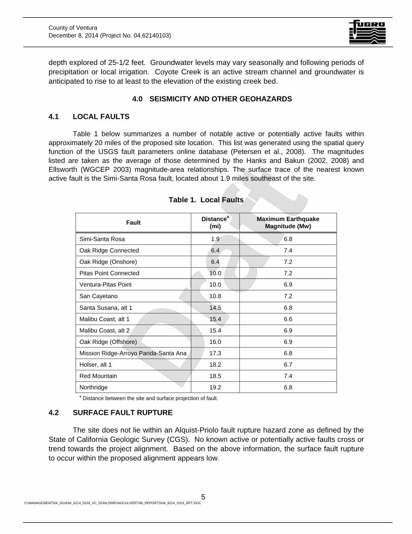
Table 1 below summarizes a number of notable active or potentially active faults within approximately 20 miles of the proposed site location. This list was generated using the spatial query function of the USGS fault parameters online database (Petersen et al., 2008). The magnitudes listed are taken as the average of those determined by the Hanks and Bakun (2002, 2008) and Ellsworth (WGCEP 2003) magnitude-area relationships. The surface trace of the nearest known active fault is the Simi-Santa Rosa fault, located about 1.9 miles southeast of the site.
Table 1. Local Faults
Fault Distancea (mi)
Maximum Earthquake Magnitude (Mw)
Simi-Santa Rosa 1.9 6.8
Oak Ridge Connected 6.4 7.4
Oak Ridge (Onshore) 6.4 7.2
Pitas Point Connected 10.0 7.2
Ventura-Pitas Point 10.0 6.9
San Cayetano 10.8 7.2
Santa Susana, alt 1 14.5 6.8
Malibu Coast, alt 1 15.4 6.6
Malibu Coast, alt 2 15.4 6.9
Oak Ridge (Offshore) 16.0 6.9
Mission Ridge-Arroyo Parida-Santa Ana 17.3 6.8
Holser, alt 1 18.2 6.7
Red Mountain 18.5 7.4
Northridge 19.2 6.8 a Distance between the site and surface projection of fault.
4.2 SURFACE FAULT RUPTURE
The site does not lie within an Alquist-Priolo fault rupture hazard zone as defined by the State of California Geologic Survey (CGS). No known active or potentially active faults cross or trend towards the project alignment. Based on the above information, the surface fault rupture to occur within the proposed alignment appears low.
County of Ventura December 8, 2014 (Project No. 04.62140103)
6 O:\MANAGEMENT\04_2014\04_6214_0103_VC_DONLONROADCULVERT\06_REPORTS\04_6214_0103_RPT.DOC
4.3 STRONG GROUND MOTION
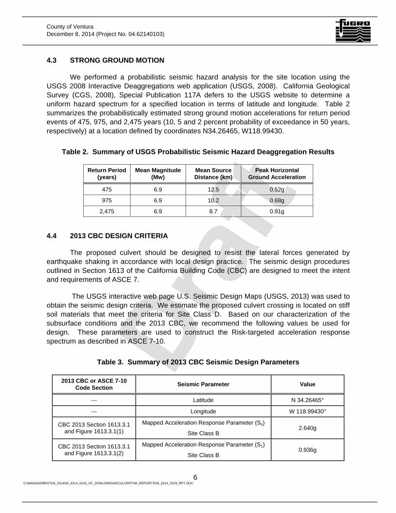
We performed a probabilistic seismic hazard analysis for the site location using the USGS 2008 Interactive Deaggregations web application (USGS, 2008). California Geological Survey (CGS, 2008), Special Publication 117A defers to the USGS website to determine a uniform hazard spectrum for a specified location in terms of latitude and longitude. Table 2 summarizes the probabilistically estimated strong ground motion accelerations for return period events of 475, 975, and 2,475 years (10, 5 and 2 percent probability of exceedance in 50 years, respectively) at a location defined by coordinates N34.26465, W118.99430.
Table 2. Summary of USGS Probabilistic Seismic Hazard Deaggregation Results
Return Period (years)
Mean Magnitude (Mw)
Mean Source Distance (km)
Peak Horizontal Ground Acceleration
475 6.9 12.5 0.52g
975 6.9 10.2 0.68g
2,475 6.9 8.7 0.91g
4.4 2013 CBC DESIGN CRITERIA
The proposed culvert should be designed to resist the lateral forces generated by earthquake shaking in accordance with local design practice. The seismic design procedures outlined in Section 1613 of the California Building Code (CBC) are designed to meet the intent and requirements of ASCE 7.
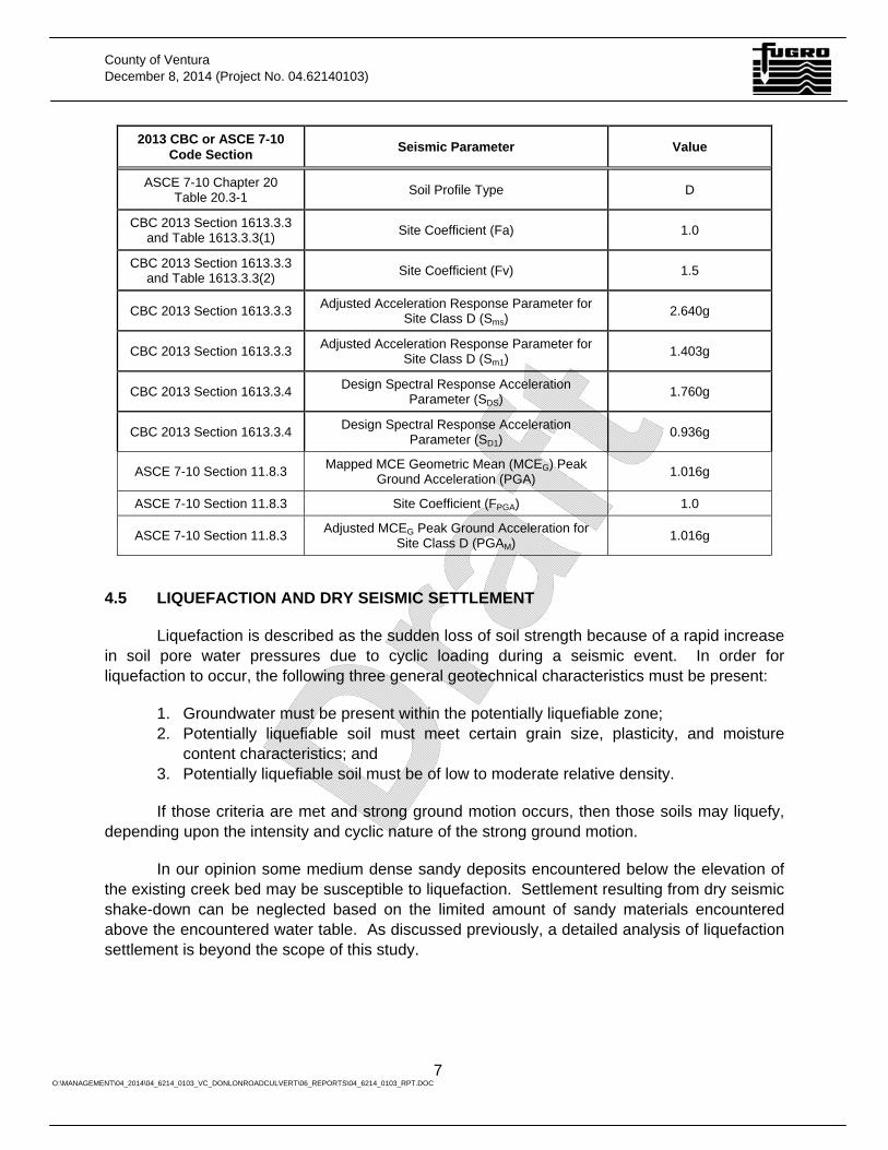
The USGS interactive web page U.S. Seismic Design Maps (USGS, 2013) was used to obtain the seismic design criteria. We estimate the proposed culvert crossing is located on stiff soil materials that meet the criteria for Site Class D. Based on our characterization of the subsurface conditions and the 2013 CBC, we recommend the following values be used for design. These parameters are used to construct the Risk-targeted acceleration response spectrum as described in ASCE 7-10.
Table 3. Summary of 2013 CBC Seismic Design Parameters
2013 CBC or ASCE 7-10 Code Section Seismic Parameter Value
--- Latitude N 34.26465°
--- Longitude W 118.99430°
CBC 2013 Section 1613.3.1 and Figure 1613.3.1(1)
Mapped Acceleration Response Parameter (Ss)
Site Class B 2.640g
CBC 2013 Section 1613.3.1 and Figure 1613.3.1(2)
Mapped Acceleration Response Parameter (S1)
Site Class B 0.936g
County of Ventura December 8, 2014 (Project No. 04.62140103)
7 O:\MANAGEMENT\04_2014\04_6214_0103_VC_DONLONROADCULVERT\06_REPORTS\04_6214_0103_RPT.DOC
2013 CBC or ASCE 7-10 Code Section Seismic Parameter Value
ASCE 7-10 Chapter 20 Table 20.3-1 Soil Profile Type D
CBC 2013 Section 1613.3.3 and Table 1613.3.3(1) Site Coefficient (Fa) 1.0
CBC 2013 Section 1613.3.3 and Table 1613.3.3(2) Site Coefficient (Fv) 1.5
CBC 2013 Section 1613.3.3 Adjusted Acceleration Response Parameter for Site Class D (Sms)
2.640g
CBC 2013 Section 1613.3.3 Adjusted Acceleration Response Parameter for Site Class D (Sm1)
1.403g
CBC 2013 Section 1613.3.4 Design Spectral Response Acceleration Parameter (SDS) 1.760g
CBC 2013 Section 1613.3.4 Design Spectral Response Acceleration Parameter (SD1)
0.936g
ASCE 7-10 Section 11.8.3 Mapped MCE Geometric Mean (MCEG) Peak Ground Acceleration (PGA) 1.016g
ASCE 7-10 Section 11.8.3 Site Coefficient (FPGA) 1.0
ASCE 7-10 Section 11.8.3 Adjusted MCEG Peak Ground Acceleration for Site Class D (PGAM) 1.016g
4.5 LIQUEFACTION AND DRY SEISMIC SETTLEMENT
Liquefaction is described as the sudden loss of soil strength because of a rapid increase in soil pore water pressures due to cyclic loading during a seismic event. In order for liquefaction to occur, the following three general geotechnical characteristics must be present:
1. Groundwater must be present within the potentially liquefiable zone; 2. Potentially liquefiable soil must meet certain grain size, plasticity, and moisture
content characteristics; and 3. Potentially liquefiable soil must be of low to moderate relative density.
If those criteria are met and strong ground motion occurs, then those soils may liquefy, depending upon the intensity and cyclic nature of the strong ground motion.
In our opinion some medium dense sandy deposits encountered below the elevation of the existing creek bed may be susceptible to liquefaction. Settlement resulting from dry seismic shake-down can be neglected based on the limited amount of sandy materials encountered above the encountered water table. As discussed previously, a detailed analysis of liquefaction settlement is beyond the scope of this study.
County of Ventura December 8, 2014 (Project No. 04.62140103)
8 O:\MANAGEMENT\04_2014\04_6214_0103_VC_DONLONROADCULVERT\06_REPORTS\04_6214_0103_RPT.DOC
4.6 SLOPE STABILITY
Final embankment slopes descending to the active Coyote Creek drainage are currently proposed at a 1-1/2H:1V. Slope stability analyses was performed for a 20-foot high slope inclined at 1-1/2H:1V and assuming a homogeneous soil with an average soil friction angle of 30 degrees and a cohesion component of 300 pounds per square foot (psf). Slope stability analyses was performed for a static case and a pseudostatic case (kh=0.15g) assuming a static groundwater level at the creek bed elevation. A rapid drawdown case was also performed, which considers the groundwater building up within the slope during a storm event and then draining quickly from the channel, leaving a build-up of hydrostatic pressure within the backfill. The rapid drawdown case is not combined with earthquake loading.
The results indicate a factor of safety of 2.15 for the static case, 1.68 for the pseudostatic case, and 1.38 for the rapid drawdown case. Although the analyses suggest that the proposed 1-1/2V:1V slopes will satisfy local standards for slope stability, the newly graded embankment slopes are subject to erosion and surficial sloughing from higher velocity flows in the creek. We recommend the embankment slopes in the area of the culvert crossing are armored with Rock Slope Protection (RSP). The RSP should be designed in accordance with Caltrans standards.
5.0 CONCLUSIONS AND RECOMMENDATIONS
5.1 EARTHWORK AND GRADING
Site preparation and fill placement for culvert and storm drain structures for the project should generally be performed according to the latest version of Section 16 - Clearing and Grubbing, and Section 19 - Earthwork, of Caltrans Standard Specifications (Caltrans 2010). We recommend that, unless otherwise noted, fill materials be placed and compacted in accordance with Section 19 - Earthwork of the Caltrans Standard Specifications.
5.2 CLEARING AND GRUBBING
Prior to commencing grading operations in areas that will receive compacted fill, soil containing debris, organics, pavement, abandoned utilities, uncompacted/undocumented fill, or other unsuitable materials, should be removed. Depressions or disturbed areas left from the removal of such material should be replaced with compacted fill. A Fugro representative should review the exposed subgrade (and/or temporary construction slope) to confirm whether or not deepening or widening of the excavation is recommended prior to placing fill. Subgrade preparation is further discussed in the following sections.
5.3 OVEREXCAVATION
We recommend the existing soil materials directly below the culvert wall footings and below the proposed reinforced concrete box storm drain be overexcavated and recompacted to provide a firm, uniform bearing layer.
County of Ventura December 8, 2014 (Project No. 04.62140103)
9 O:\MANAGEMENT\04_2014\04_6214_0103_VC_DONLONROADCULVERT\06_REPORTS\04_6214_0103_RPT.DOC
Overexcavation below the arch culvert structure should extend a minimum of 3 feet below the deepest structural element and 3 feet outside the edges of the footings. Removals below the RCB storm drain should extend 12 inches below the structure bottom and 12 inches outside the structure.
The subgrade soils should be observed and approved by Fugro prior to preparing the subgrade or placing compacted fill. Overexcavation depths may be increased to remove soft, compressible or otherwise unsuitable soils if present at or below the minimum excavation depth. Recommendations for subgrade preparation and fill placement are in subsequent sections.
5.4 SUBGRADE PREPARATION
If the subgrade conditions are acceptable to Fugro, the exposed surface should be scarified to a depth of 6 inches, moisture-conditioned to within 2 percent of optimum moisture, and recompacted to a relative compaction of at least 90 percent (i.e., 90 percent of the maximum dry density determined from ASTM D1557), unless noted otherwise.
Within Coyote Creek, high water content and the presence of loose and/or soft fill and alluvial materials could make compaction of the subgrade and structural section materials relatively difficult. The project specifications should provide for review of the excavation by the geotechnical engineer, and for deepening excavations, if needed, to remove unsuitable subgrade material prior to placement of compacted fill materials.
If exposed subgrade materials are yielding or are subject to pumping under construction traffic, stabilization of the subgrade will be required prior to the placement of overlying fill or the construction of foundation elements. In that case, the requirement to scarify and re-compact the subgrade may be waived. Potential subgrade stabilization measures that may be effective are outlined below.
5.5 SPECIAL SUBGRADE STABILIZATION MEASURES
Special stabilization measures may be required if soft or pumping subgrades are encountered during construction. Those measures may be required in order to provide a firm and unyielding subgrade surface. If exposed subgrade conditions warrant stabilization, the contractor, after considering input from the design engineer, geotechnical engineer, and owner, should be responsible for design and implementation of those subgrade stabilization techniques.
On a preliminary basis, potential subgrade stabilization measures could potentially consist of:
• The use of geogrid or geosynthetic reinforcement placed beneath crushed rock fill; [Caltrans (2013) recommends the use of Subgrade Enhancement Geotextile (SEGT) or Subgrade Enhancement Geogrid (SEGG) for stabilization].
• The working of crushed rock fill (2- to 3-inch minus crushed rock) into clayey subgrade soils; or
County of Ventura December 8, 2014 (Project No. 04.62140103)
10 O:\MANAGEMENT\04_2014\04_6214_0103_VC_DONLONROADCULVERT\06_REPORTS\04_6214_0103_RPT.DOC
• The placement of a mud- or lean-concrete mat as a working surface.
Whether these measures are required or not will depend on the depth of the excavation relative to the groundwater level, the moisture content of subgrade materials, and to some extent the contractor's means and methods. Past experience suggests that rock fill thicknesses between 1 and 2 feet may be required to provide a suitable subgrade surface upon which fill materials can be placed and compacted. A layer of filter fabric may be required to separate the crushed rock fill from the underlying or overlying soil materials. Subgrade stabilization methods often require some degree of trial and error in the field.
5.6 COMPACTED FILL
Compacted fill materials for the proposed site improvements will consist of on-site materials, general import borrow, and other select fill materials required for arch culvert and storm drain structure construction. Materials discussed or used in this report, as they relate to the Standard Specifications, are discussed below.
5.6.1 On-Site Soil Materials
On-site soils and existing fill free of organics, oversize rock (over 3 inches in diameter), trash, debris, corrosive, and other deleterious or unsuitable materials, can be used for compacted fill for general fill and embankment construction. However, we do not expect that on-site soils will meet the requirements for select fill material (for example aggregate base or structure backfill). We note that aeration and drying of the on-site soils may be necessary prior to placement and compaction. Control of the soil moisture content and compaction layer thickness will be required to achieve the minimum specified compaction. The fine-grained soils encountered will be particularly sensitive to changes in moisture content, and can be relatively difficult to compact.
5.6.2 Imported Borrow
Imported borrow shall be free of organics, oversize rock, trash, debris, corrosive, and other deleterious or unsuitable materials. In addition, imported borrow shall also have the following characteristics:
• Expansion index less than 20; • Plasticity index less than 15; • Sand equivalent of at least 20; • Less than 50 percent passing no. 200 sieve; and • R-value of at least 25 where placed within 2 feet of pavement structural sections.
5.6.3 Structure Backfill
Structure backfill for the arch culvert shall meet the requirements of the manufacturer specifications and other agency requirements. Other structural backfill shall meet the
County of Ventura December 8, 2014 (Project No. 04.62140103)
11 O:\MANAGEMENT\04_2014\04_6214_0103_VC_DONLONROADCULVERT\06_REPORTS\04_6214_0103_RPT.DOC
requirements provided in Section 19 of the Standard Specifications and meet the following additional criteria:
• Expansion index less than 20; • Plasticity index less than 15; • Sand equivalent of at least 20; • 100 percent passing 3-in sieve, 35 to 100 percent passing no. 4 sieve, and 20 to 100
percent passing the no. 30 sieve.
Onsite sandy materials may be suitable as structure backfill, however, the materials may be thinly bedded and segregation of the granular soils for use as structure backfill may be difficult.
5.6.4 Pipe Bedding and Pipe Zone Backfill
Clean sand with a minimum SE of 30 as described in Section 306-1.2.1 of the Standard Specifications for Public Works Construction ("Greenbook," 2006) should be used for pipe bedding and pipe zone backfill. However, the materials used should meet the requirements of the local agency.
5.6.5 Trench Backfill
Materials placed above the pipe zone are considered trench backfill. On-site soils free of deleterious or oversize material should be suitable for use as trench backfill unless other specific materials are required by the local agency.
5.6.6 Drainage Material
Class 2 permeable material, conforming to Section 68-1.025 of the Caltrans Standard Specifications should be used for drainage material. Class 1 materials could also be used provided they are used in conjunction with filter fabric or a separation geotextile. Geogrid Reinforcement should consist of Tensar BX 1100 or equivalent. Filter Fabric should consist of Mirafi 180N or equivalent.
5.6.7 Fill Placement and Compaction Requirements
Fill should be placed and compacted to at least the minimum relative compaction recommended in this report. Fill should be placed in horizontal lifts not exceeding 8 inches in compacted thickness, and moisture content of the fill should be between 2 percent below to 2 percent above optimum. Each layer should be spread evenly and thoroughly blade-mixed during the spreading to provide relative material uniformity within each layer. Soft or yielding materials have relatively low strength and can compromise the stability of the pavement section if left in place. Soft or yielding materials encountered during fill placement should be removed and replaced with properly compacted fill material prior to placing the next layer.
We recommend that, unless otherwise noted, fill and backfill materials below the arch culvert structure should be compacted to at least 95 percent relative compaction, as determined
County of Ventura December 8, 2014 (Project No. 04.62140103)
12 O:\MANAGEMENT\04_2014\04_6214_0103_VC_DONLONROADCULVERT\06_REPORTS\04_6214_0103_RPT.DOC
by the latest approved edition of ASTM Test Method D1557 and in accordance with manufacturer specifications. Compacted fill associated with the RCB structure should be compacted to at least 90 percent relative compaction.
5.7 CONSTRUCTION CONSIDERATIONS
5.7.1 Excavation Effort
Drill holes advanced for this study were excavated with hand augers and a hollow-stem-auger drill rig with light to moderate effort. We expect that the onsite materials can be excavated using conventional earth-moving excavation equipment in good working order.
5.7.2 Temporary Excavations
Temporary slopes, excavations, and shoring should conform to federal Occupational Safety and Health Administration regulations and any other local ordinances and building codes, as required. The contractor should be responsible for the design of and all safety issues regarding temporary excavations and worker safety. The contractor should continuously monitor the temporary slopes and support and remove or stabilize any loose or unstable soil masses.
Excavations over 4 feet deep should be designed by the contractor according to the applicable safety regulations and standards of (Cal) OSHA. Based on the OSHA guidelines and soil conditions encountered, we expect that the on-site soil exposed in temporary excavations can generally be sloped to inclinations of 1v:1h. Slopes may need to be constructed flatter than 1h:1v or temporary shoring may be locally required for higher slopes or where adverse soil conditions are present. Stockpiled material or equipment should not be placed closer than 5 feet from any slope crest. Dewatering and erosion protection, such as controlled runoff drainage, should be provided as necessary.
6.0 CULVERT DESIGN
Precast concrete arch culvert bridges will be placed over the Coyote Creek channel. We understand that a CONTECH® CON/SPAN O-Series™ culvert, or similar type, will be used at the crossing. Our recommendations for geotechnical culvert design are presented below. Our recommendations were developed based on the geotechnical site conditions and are intended to satisfy the foundation design input needed by the product designer and manufacturer.
6.1 GRADING RECOMMENDATIONS
6.1.1 General
Clearing and grubbing, subgrade preparation, and special subgrade stabilization measures should be performed in accordance with our recommendations presented in earlier sections of this report. Culvert wall foundations should be underlain by at least 3 feet of structure backfill compacted to at least 95 percent relative compaction. Culvert backfill should also consist of structure backfill compacted to at least 95 percent relative compaction.
County of Ventura December 8, 2014 (Project No. 04.62140103)
13 O:\MANAGEMENT\04_2014\04_6214_0103_VC_DONLONROADCULVERT\06_REPORTS\04_6214_0103_RPT.DOC
6.1.2 Groundwater and Dewatering
Excavations should be kept free of water. Runoff should be directed away from open excavations and should not be allowed to flow across slope faces. For excavations extending below anticipated groundwater elevations, pumping of free water from open excavations may not be adequate to maintain excavations in a dry and stable state; therefore, alternative procedures may be needed. Dewatering systems, where required, should be designed, installed, and operated by an experienced contractor specializing in groundwater dewatering systems. Before implementing a dewatering system, we recommend that the contractor conduct a dewatering test program to evaluate the feasibility and efficiency of the proposed dewatering system.
Caving or flowing granular soils may be encountered if sands below the groundwater table are encountered and not retained. Caving of the materials is also a consideration for unshored near-vertical cuts.
Dewatering efforts should endeavor to maintain water levels at least 2 feet below the lowest point of the excavated surface (defined by the elevation of any overexcavated surface). Even so, construction difficulties may be encountered because of the presence of soft soils or as a result of pumping soils developing during construction activities such as compaction. Subgrade stabilization measures, as discussed in Section 5.5, may be required to provide a subgrade that is suitable for construction activities. The contractor should verify that the water level has been lowered to at least 2 feet below the lowest planned excavation depth by potholing or other methods prior to beginning excavation work for the culverts.
6.2 ALLOWABLE BEARING PRESSURE
Culverts bearing on at least 3 feet of compacted fill placed in accordance with recommendations herein can be designed using a maximum allowable bearing pressure of 4,000 psf. The maximum allowable bearing pressures can be increased by one-third when considering short-term wind or seismic loads.
6.3 STATIC SETTLEMENT
For anticipated foundation loads and subsurface conditions at the creek crossings, we estimate total settlement could be on the order of 2-1/2 inches for culverts that are placed on at least 3 feet of compacted structural fill. Given the interbedded nature of the subgrade soils (sands and clays), we anticipate that approximately 1 inch of the estimated total settlement will occur in the form of elastic settlement of the sandy layers and will primarily occur during fill placement and placement of the culverts. Differential settlement is estimated to be about 1 inch.
6.4 RESISTANCE TO LATERAL LOADS
6.4.1 Sliding Resistance
Resistance to lateral loading can be provided by sliding friction acting along the base of the culverts combined with passive pressure acting on the sides of the walls. Ultimate sliding
County of Ventura December 8, 2014 (Project No. 04.62140103)
14 O:\MANAGEMENT\04_2014\04_6214_0103_VC_DONLONROADCULVERT\06_REPORTS\04_6214_0103_RPT.DOC
resistance generated through a soil/concrete or soil/soil interface can be estimated using a coefficient of friction of 0.35.
6.4.2 Passive Resistance
Ultimate passive resistance may be estimated using an equivalent fluid weight (EFW) of 300 pounds pcf for walls or foundations bearing against compacted backfill. Passive resistance should not be used for the upper 1 foot of soil that is not overlain at the ground surface by a slab-on-grade or pavement. We recommend a factor of safety of at least 1.5 be used for evaluating foundation sliding or overturning.
6.5 LATERAL EARTH PRESSURES
6.5.1 General
Walls that are free to rotate or translate laterally (e.g., cantilevered) through a horizontal-distance-to-wall-height ratio of no less than 0.004 are referred to as unrestrained or yielding. Such walls can generally move enough to develop active conditions. Walls that are unable to rotate or deflect laterally (e.g. fixed at the top) are referred to as restrained or non-yielding.
If backfill materials behind the wingwalls consist of imported cohesionless soils, then unrestrained walls can usually be designed for active earth pressure conditions, which are lower than at-rest conditions. Restrained walls with imported cohesionless backfills should be designed for at-rest earth pressure conditions. For cohesive backfills, both unrestrained and restrained walls should be designed for at-rest conditions because cohesive soils creep, undergo stress relaxation, and cannot sustain active conditions.
The native soils consist of interbedded silty sands, clayey sands, and sandy clays that should be considered cohesive with regard to retaining wall backfill. If native soils are planned for backfill behind the wing walls, than at-rest earth pressure conditions should apply for design.
6.5.2 Equivalent Fluid Weights
Table 4 presents recommended equivalent fluid weights for level backfill and static conditions for the at-rest and active cases under either drained or undrained conditions. Drained conditions imply that drainage measures are incorporated into the wall to preclude the buildup of hydrostatic pressure.
Table 4. Recommended Equivalent Fluid Weights (pcf) for Retaining Wall Design
Wall Backfill Drained Undrained
Active At-Rest Active At-Rest
Level backfill 40 60 80 90
County of Ventura December 8, 2014 (Project No. 04.62140103)
15 O:\MANAGEMENT\04_2014\04_6214_0103_VC_DONLONROADCULVERT\06_REPORTS\04_6214_0103_RPT.DOC
7.0 REINFORCED CONCRETE BOX STORM DRAIN DESIGN
7.1.1 External Loads
External loads on the concrete storm drain structures could consist of loads resulting from the overlying earth materials, construction activities, vehicular traffic, or other post-construction land uses. The proposed RCB should be designed to resist these anticipated surcharge loads.
Loads on the RCB due to the overlying soil will be dependent upon the depth of placement, the type and method of backfill, the type of pipe, the configuration of the trench, and whether or not any fill will be placed above the ground surface. The earth loads on the pipe can be estimated using formulas developed by Marston (1930) and are dependent on whether "trench conditions" or "embankment conditions" exist along the alignment. Trench conditions are defined as those in which the RCB is installed in a relatively narrow trench, cut in undisturbed ground, and covered with earth backfill to the original ground surface. Embankment conditions are defined as those in which the RCB is covered with fill above the ground surface or when a trench in undisturbed ground is so wide that trench wall side friction does not affect the load on the pipe. Most likely, "trench" conditions will be most appropriate for RCB design. When using Marston's formulas, the total unit weight of the backfill materials should be assumed to be 125 pounds pcf.
7.1.2 Modulus of Soil Reaction
Flexible and semi-rigid pipeline-type structures are typically designed to withstand a certain amount of deflection from the applied earth loads. Those deflections can be estimated with the aid of equations presented by Spangler and Handy (1982) or Howard et al. (1995).
Modulus of soil reaction values (E') were estimated from correlations and information presented in Hartley and Duncan (1987). Based on the subsurface conditions encountered in our explorations, we recommend a modulus of soil reaction value equal to 1,500 psi be used for design of the proposed RCB. The E'value is considered applicable for a combined trench/pipeline system that includes compacted pipe zone material at the springline and that the trench width be at least 1.75 times the width of the box.
7.1.3 Uplift Pressures
The proposed storm drain pipe may be subjected to hydrostatic uplift pressure from groundwater when the system is empty. Therefore, the potential for uplift of the RCB should be considered in the design. Groundwater should be assumed to be within 5 feet of the ground surface for uplift evaluations. Uplift resistance can be provided by the weight of soil above the pipe and the soil frictional resistance. The effective unit weight of the soil above the RCB should be assumed to be 60 pounds pcf. A total unit weight of 120 pcf can be used for the weight of soil above the assumed groundwater level. The frictional resistance of a rectangular soil prism (soil-soil or soil-concrete interface) can be assumed to be 15 pounds psf per foot of depth.
County of Ventura December 8, 2014 (Project No. 04.62140103)
16 O:\MANAGEMENT\04_2014\04_6214_0103_VC_DONLONROADCULVERT\06_REPORTS\04_6214_0103_RPT.DOC
8.0 SOIL CHEMISTRY AND CORROSION
8.1 TEST RESULTS
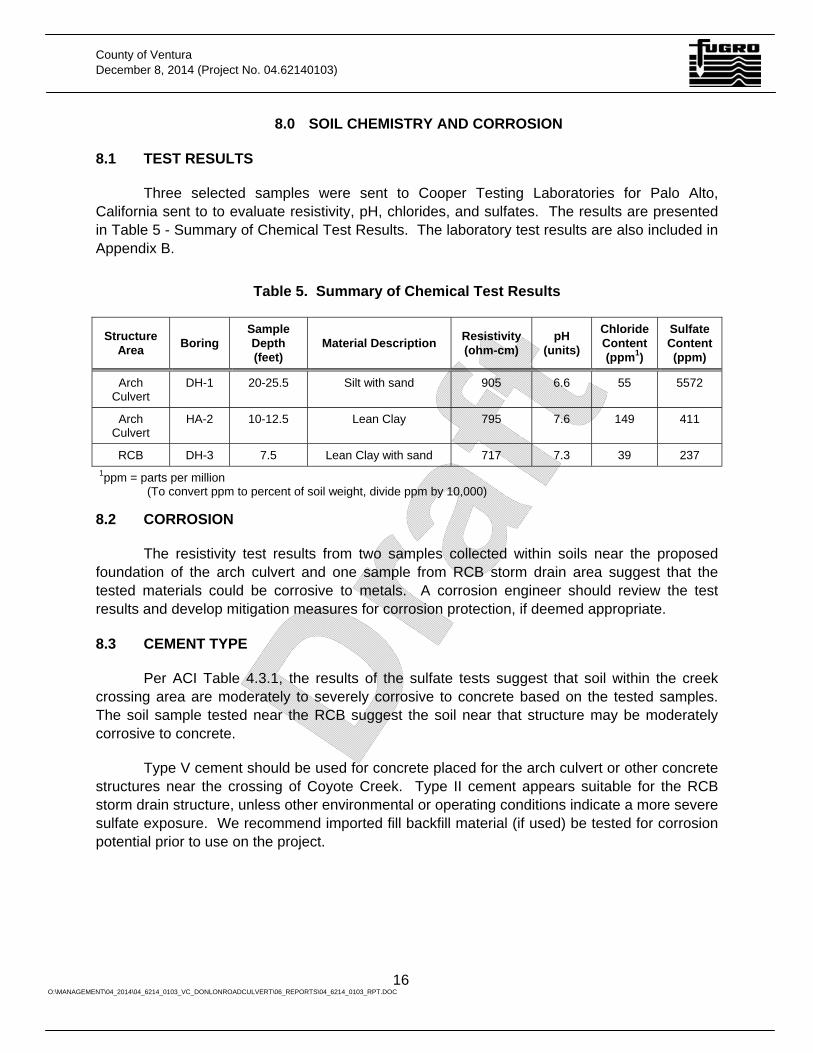
Three selected samples were sent to Cooper Testing Laboratories for Palo Alto, California sent to to evaluate resistivity, pH, chlorides, and sulfates. The results are presented in Table 5 - Summary of Chemical Test Results. The laboratory test results are also included in Appendix B.
Table 5. Summary of Chemical Test Results
Structure Area Boring
Sample Depth (feet)
Material Description Resistivity (ohm-cm)
pH (units)
Chloride Content (ppm1)
Sulfate Content(ppm)
Arch Culvert
DH-1 20-25.5 Silt with sand 905 6.6 55 5572
Arch Culvert
HA-2 10-12.5 Lean Clay 795 7.6 149 411
RCB DH-3 7.5 Lean Clay with sand 717 7.3 39 237 1ppm = parts per million (To convert ppm to percent of soil weight, divide ppm by 10,000)
8.2 CORROSION
The resistivity test results from two samples collected within soils near the proposed foundation of the arch culvert and one sample from RCB storm drain area suggest that the tested materials could be corrosive to metals. A corrosion engineer should review the test results and develop mitigation measures for corrosion protection, if deemed appropriate.
8.3 CEMENT TYPE
Per ACI Table 4.3.1, the results of the sulfate tests suggest that soil within the creek crossing area are moderately to severely corrosive to concrete based on the tested samples. The soil sample tested near the RCB suggest the soil near that structure may be moderately corrosive to concrete.
Type V cement should be used for concrete placed for the arch culvert or other concrete structures near the crossing of Coyote Creek. Type II cement appears suitable for the RCB storm drain structure, unless other environmental or operating conditions indicate a more severe sulfate exposure. We recommend imported fill backfill material (if used) be tested for corrosion potential prior to use on the project.
County of Ventura December 8, 2014 (Project No. 04.62140103)
17 O:\MANAGEMENT\04_2014\04_6214_0103_VC_DONLONROADCULVERT\06_REPORTS\04_6214_0103_RPT.DOC
9.0 CONTINUING SERVICES
9.1 PLAN REVIEW
We recommend that Fugro be provided the opportunity to review and comment on the geotechnical aspects of the project plans and specifications before they are finalized. The purpose of that review will be to evaluate if the recommendations in this report have been properly interpreted and implemented in the design and specifications.
9.2 CONSTRUCTION MONITORING
Users of this report should recognize that the construction process is an integral design component with respect to the geotechnical aspects of a project, and that geotechnical engineering is inexact due to the variability of natural and man-induced processes, which can produce unanticipated or changed conditions. Proper geotechnical observation and testing during construction, thus, are imperative in allowing the geotechnical engineer the opportunity to continue to evaluate assumptions made during the design process. Therefore, we recommend that Fugro be retained during site grading and foundation construction to observe compliance with the design concepts and geotechnical recommendations, and to allow design changes in the event that subsurface conditions, or methods of construction, differ from those anticipated.
County of Ventura December 8, 2014 (Project No. 04.62140103)
18 O:\MANAGEMENT\04_2014\04_6214_0103_VC_DONLONROADCULVERT\06_REPORTS\04_6214_0103_RPT.DOC
10.0 REFERENCES
American Concrete Institute (2005), Building Code Requirements for Structural Concrete and Commentary 318-05.
American Society of Testing and Materials (ASTM) (latest edition), ASTM Annual Book of Standards.
American Society of Civil Engineers (ASCE) (2010), Minimum Design Loads for Buildings and Other Structures, ASCE 7-10.
California Building Code (2013), published by the International Conference of Building Officials, Whittier, California, and California Building Standards Commission, Sacramento, California.
California Department of Transportation (latest revision), Highway Design Manual.
California Department of Transportation (latest revision), Standard Specifications.
California Department of Transportation (latest revision), Standard Plans.
California Department of Transportation (latest revision), Corrosion Guidelines.
Dibblee, T.W., Jr. (1992a), Geologic Map of the Moorpark Quadrangle, Ventura County, California.
Dibblee, T.W., Jr. (1992b), Geologic Map of the Santa Paula Quadrangle, Ventura County, California.
Hanks, T. C., and W. H. Bakun (2002), A bilinear source-scaling model for M-log A observations of continental earthquakes, Bull. Seismol. Soc. Am., 92 , 1841.
Hanks, T. C., and W. H. Bakun (2008), M-log A observations of recent large earthquakes, Bull. Seismol. Soc. Am., 98, 490.
Petersen, Mark D., Frankel, Arthur D., Harmsen, Stephen C., Mueller, Charles S., Haller, Kathleen M., Wheeler, Russell L., Wesson, Robert L., Zeng, Yuehua, Boyd, Oliver S., Perkins, David M., Luco, Nicolas, Field, Edward H., Wills, Chris J., and Rukstales, Kenneth S., (2008), Documentation for the 2008 Update of the United States National Seismic Hazard Maps: U.S. Geological Survey Open-File Report 2008-1128, 61 p.
United States Geological Survey (USGS website, 2013), U.S. Seismic Design Maps Application. http://geohazards.usgs.gov/designmaps/us/application.php
Working Group on California Earthquake Probabilities [WGCEP] (2003), Earthquake probabilities in the San Francisco Bay Region: 2002 to 2031, U.S. Geol. Surv. Open File Rep., 03-214.

PLATES
NORTH
VICINITY MAPDonlon Road Realignment Project
Ventura County, California
M:\D
rafti
ng\J
OB
FILE
S\2
014\
04.6
2140
103\
Dra
win
gs\A
04.6
2140
103-
01 v
icn.
dwg
11-0
6-20
14 -
2:52
pm
Project No.
PLATE 1
04.62140103County of Ventura
BASE MAP SOURCE: Thomas Guide 2001, Ventura County (p. 494 & 495).
FEET
0 2400
PROJECTSITE
DO
NLO
N R
OAD
DH-02
HA-03
325
320
315
310
305
310
315
320
325
325
320
A
DH-01
DONLO
N R
OAD
LaCUM
BRE R
OAD
SO
MIS
RO
AD
(SR
-34)
LOS ANGELES AVENUEHIGHWAY 118
A'
COYO
TE CREEK
HA-01HA-02
PROPOSEDCULVERT
PROPOSED REINFORCEDCONCRETE BOX
* CAD file provided by the County of Ventua.* Google Earth Pro (2014), Aerial photograph.
BASE MAP SOURCE:
LEGEND
Approximate locationof drill hole
Approximate locationof hand auger boring
Cross Section
M:\D
rafti
ng\J
OB
FILE
S\2
014\
04.6
2140
103\
Dra
win
gs\B
04.6
2140
103-
02 e
xplo
r.dw
g 12
-04-
2014
- 2:
59pm
SUBSURFACE EXPLORATIONLOCATION PLAN
Donlon Road Realignment ProjectVentura County, California
NORTH
Project No.
PLATE 2
04.62140103County of Ventura
FEET
0 60 120
A A'
NORTH
REGIONAL GEOLOGIC MAPDonlon Road Realignment Project
Ventura County, California
M:\D
rafti
ng\J
OB
FILE
S\2
014\
04.6
2140
103\
Dra
win
gs\A
04.6
2140
103-
03 g
eo.d
wg
11-0
6-20
14 -
2:43
pm
Project No.
PLATE 3
04.62140103County of Ventura
BASE MAP SOURCE: * Dibblee (1992), Geologic Map of the Moorpark Quadrangle, Ventura County, California. * Dibblee (1992), Geologic Map of the Santa Paula Quadrangle, Ventura County, California.
FEET
0 2000
PROJECTSITE
LEGEND
Alluvium
Stream ChannelDeposits
Older alluvium
Saugus Formation -light gray to lightbrown gravel
Las Posas Sand -fine to mediumgrained sandy silt
Formation Contact - dashed where inferred orindefinite
Fault - dashed where indefinite or inferred, dottedwhere concealed, relative vertical movementshown by U/D (U = upthrown side, D =downthrown side), short arrow indicates dip of faultplane, sawteeth are on upper plate of low anglethrust fault
Anticline - dashed where inferred or indefinite
Syncline - dashed where inferred or indefinite
Strike and dip of beds:
Inclined
Vertical
300
310
320
330
0 10 20 30 40 50 60 70 80 90 100 110 120 130 140 150 160 170 180 190
A A'
290
280
270
260
300
310
320
330
290
280
270
260
250 250
ML
SM
CL
SP-SC
CL
SM
ProposedDonlon Road
2000
20
Horizontal and VerticalScales in Feet
Project No.
PLATE 4
04.62140103County of Ventura
SUBSURFACE PROFILE CROSS SECTION A-A'Donlon Road Realignment Project
Ventura County, California
M:\D
rafti
ng\J
OB
FILE
S\2
014\
04.6
2140
103\
Dra
win
gs\B
04.6
2140
103
Sec
t A.d
wg
12-0
4-20
14 -
2:33
pm
LEGEND
SILT with sand
Silty SAND
Sandy lean CLAY
Poorly graded SAND with clay
Poorly graded SAND with silt
Silty SAND to Sandy SILT
Sandy Fat CLAY
Measured Groundwater level
ML
SM
CL
SP-SC
SP-SM
SM-ML
CH
APPENDIX A - SUBSURFACE EXPLORATION
County of Ventura December 5, 2014 (Project No. 04.62140103)
A-1 O:\MANAGEMENT\04_2014\04_6214_0103_VC_DONLONROADCULVERT\06_REPORTS\04_6214_0103_RPT.DOC
APPENDIX A SUBSURFACE EXPLORATION
INTRODUCTION
The contents of this appendix shall be integrated with the geotechnical engineering study of which it is a part. The data contained in this appendix shall not be used in whole or in part as a sole source for information or recommendations regarding the subject site.
The subsurface exploration program for the proposed project consisted of the excavation of 3 hollow-stem-auger drill holes and 3 hand auger drill holes within the limits of the proposed development. The approximate locations of the excavations are shown on Plate 2.
HOLLOW-STEM-AUGER DRILL HOLES
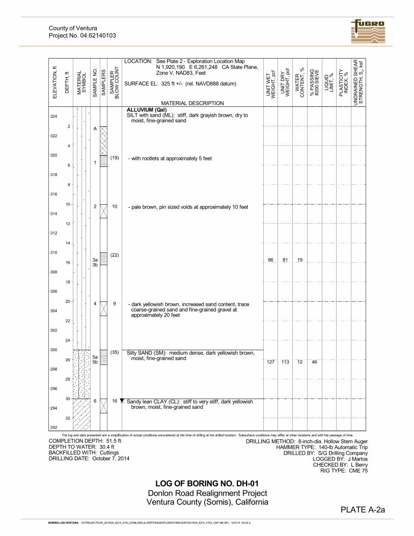
Three 8-inch-diameter hollow-stem-auger drill holes (DH-1 through DH-3) were excavated on October 7 and 8, 2014. The drill holes were excavated to depths of about 25 to 50 feet below the existing ground surface using a CME 75 truck-mounted drill rig operated by S/G Drilling Company of Lompoc, California. After completion the drill holes were backfilled with cuttings generated during excavation.
HAND AUGER DRILL HOLES
Three 4-inch-diameter hand auger drill holes were excavated on-site on October 9, 2014 within Coyote Canyon and along the proposed roadway alignment. We subcontracted the hand digging and sampling work to Mike’s Excavating Service of Temecula, California.
LOGGING
The excavations were performed under the observation of a senior staff engineer from Fugro, who logged the exploratory holes in general accordance with ASTM D2488 for visual soil classification. The boundaries between soil types shown on the logs are approximate and the transition between different layers may be gradual. The logs of the drill holes are presented as Plates A-2 through A-4 - Log of Drill Hole, and the logs of the hand auger drill holes are presented as Plates A-5 through A-7 - Log of Drill Hole. A key to the logs is presented on Plate A-1 - Key to Terms & Symbols Used on Logs.
SAMPLING
The drill holes were sampled at regular intervals using 3.25-inch-outside-diameter (OD) Modified California and 2-inch OD standard penetration test (SPT) split-spoon samplers. The Modified California sampler was fitted with 1-inch-tall brass ring liners to obtain relatively undisturbed samples for subsequent laboratory testing. The samplers used in the drill hole were driven by a 140-pound, above-ground, automatic-trip hammer free falling from a height of 30 inches.
County of Ventura December 5, 2014 (Project No. 04.62140103)
A-2 O:\MANAGEMENT\04_2014\04_6214_0103_VC_DONLONROADCULVERT\06_REPORTS\04_6214_0103_RPT.DOC
Bulk samples were collected during the course of the drill hole excavations from cuttings obtained from auger flights. The bulk samples were selected for classification and testing purposes and may represent a mixture of soils within the noted depths. Recovered samples were bagged and returned to the laboratory for further classification and testing.
The hand auger drill holes were sampled at regular intervals using 3.25-inch OD split-spoon hand sampler fitted with driven by a slide hammer. The hand sampler was fitted with 1-inch-tall brass ring liners to obtain relatively undisturbed samples of the subsurface materials for subsequent laboratory testing.
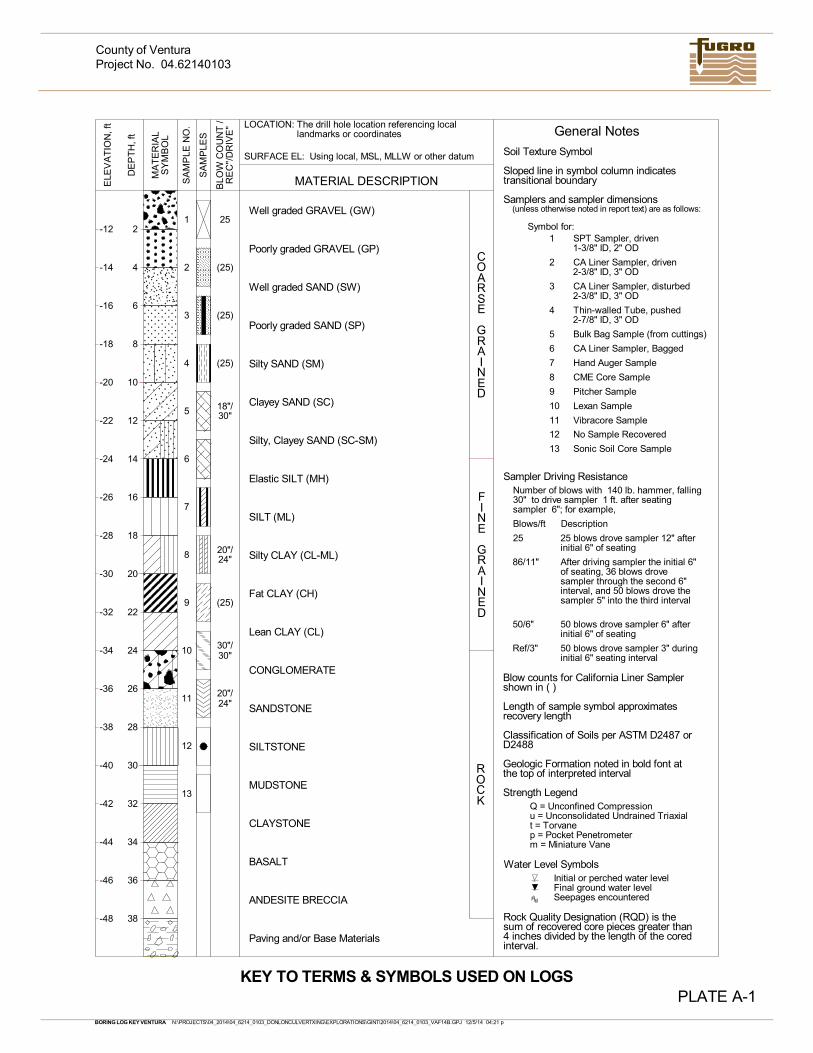
PLATE A-1
County of VenturaProject No. 04.62140103
10
Symbol for:
CA Liner Sampler, driven
Vibracore Sample
Pitcher Sample
Lexan Sample
BASALT
Sonic Soil Core Sample
No Sample Recovered
CA Liner Sampler, Bagged
13
(25)
6
11
4
Poorly graded SAND (SP)
COARSE
GRAINED
MATERIAL DESCRIPTION
Silty CLAY (CL-ML)
Silty SAND (SM)
Paving and/or Base Materials
SANDSTONE
Poorly graded GRAVEL (GP)
MUDSTONE
SY
MB
OL
SILTSTONE
Well graded SAND (SW)
Fat CLAY (CH)
MA
TE
RIA
L
SA
MP
LE N
O.
Hand Auger Sample
ANDESITE BRECCIA
7
9
5
Thin-walled Tube, pushed
CONGLOMERATE
3
FINE
GRAINED
ROCK
-12
-14
-16
-18
-20
-22
-24
-26
-28
-30
-32
-34
-36
-38
-40
-42
-44
-46
-48
2
4
6
8
10
12
14
16
18
20
22
24
26
28
30
32
34
36
38
25
Silty, Clayey SAND (SC-SM)
(25)
Elastic SILT (MH)
(25)
(25)
Lean CLAY (CL)
Sampler Driving Resistance
p = Pocket Penetrometer
Q = Unconfined Compressionu = Unconsolidated Undrained Triaxial
Initial or perched water level
Seepages encounteredFinal ground water level
Bulk Bag Sample (from cuttings)
Number of blows with 140 lb. hammer, falling30" to drive sampler 1 ft. after seatingsampler 6"; for example,
CLAYSTONE
LOCATION:
SILT (ML)
2
5
13
9
1
8
7
SA
MP
LES
Clayey SAND (SC)
The drill hole location referencing locallandmarks or coordinates
Well graded GRAVEL (GW)B
LOW
CO
UN
T /
t = Torvane
Blows/ft Description
25
Blow counts for California Liner Samplershown in ( )
Geologic Formation noted in bold font atthe top of interpreted interval
Classification of Soils per ASTM D2487 orD2488
Strength Legend
Length of sample symbol approximatesrecovery length
Water Level Symbols
SURFACE EL: Using local, MSL, MLLW or other datum
KEY TO TERMS & SYMBOLS USED ON LOGS
12
m = Miniature Vane
Samplers and sampler dimensions
Soil Texture Symbol
General Notes
Sloped line in symbol column indicatestransitional boundary
(unless otherwise noted in report text) are as follows:
3 CA Liner Sampler, disturbed
11
1 SPT Sampler, driven
6
8
2
4
CME Core Sample
12
10
BORING LOG KEY VENTURA N:\PROJECTS\04_2014\04_6214_0103_DONLONCULVERTXING\EXPLORATIONS\GINT\2014\04_6214_0103_VAF14B.GPJ 12/5/14 04:21 p
30"/30"
20"/24"
DE
PT
H, f
t
RE
C"/
DR
IVE
"
18"/30"
20"/24"
ELE
VA
TIO
N, f
t
50 blows drove sampler 3" duringinitial 6" seating interval
Ref/3"
50 blows drove sampler 6" afterinitial 6" of seating
After driving sampler the initial 6"of seating, 36 blows drovesampler through the second 6"interval, and 50 blows drove thesampler 5" into the third interval
50/6"
86/11"
25 blows drove sampler 12" afterinitial 6" of seating
Rock Quality Designation (RQD) is thesum of recovered core pieces greater than4 inches divided by the length of the coredinterval.
1-3/8" ID, 2" OD
2-3/8" ID, 3" OD
2-3/8" ID, 3" OD
2-7/8" ID, 3" OD
A
1
2
3a3b
4
5a5b
6
19
12 46
ALLUVIUM (Qal)SILT with sand (ML): stiff, dark grayish brown, dry to
moist, fine-grained sand
- with rootlets at approximately 5 feet
- pale brown, pin sized voids at approximately 10 feet
- dark yellowish brown, increased sand content, tracecoarse-grained sand and fine-grained gravel atapproximately 20 feet
Silty SAND (SM): medium dense, dark yellowish brown,moist, fine-grained sand
Sandy lean CLAY (CL): stiff to very stiff, dark yellowishbrown, moist, fine-grained sand
81
113
96
127
(19)
10
(22)
9
(35)
16
SA
MP
LER
SMATERIAL DESCRIPTION
PLA
ST
ICIT
YIN
DE
X, %
UN
DR
AIN
ED
SH
EA
RS
TR
EN
GT
H, S
u, k
sf
DE
PT
H, f
t
PLATE A-2a
UN
IT D
RY
WE
IGH
T, p
cf
2
4
6
8
10
12
14
16
18
20
22
24
26
28
30
32
LIQ
UID
LIM
IT, %
UN
IT W
ET
WE
IGH
T, p
cf
The log and data presented are a simplification of actual conditions encountered at the time of drilling at the drilled location. Subsurface conditions may differ at other locations and with the passage of time.
SA
MP
LE N
O.
MA
TE
RIA
LS
YM
BO
L
ELE
VA
TIO
N, f
t
WA
TE
RC
ON
TE
NT
, %
% P
AS
SIN
G#2
00 S
IEV
E
SA
MP
LER
BLO
W C
OU
NT
DEPTH TO WATER: 30.4 ft
LOCATION:
DRILLING METHOD: 8-inch-dia. Hollow Stem AugerHAMMER TYPE: 140-lb Automatic Trip
DRILLED BY: S/G Drilling CompanyLOGGED BY: J MartosCHECKED BY: L Berry
RIG TYPE: CME 75
SURFACE EL: 325 ft +/- (rel. NAVD888 datum)
COMPLETION DEPTH: 51.5 ft
DRILLING DATE: October 7, 2014BACKFILLED WITH: Cuttings
LOG OF BORING NO. DH-01
324
322
320
318
316
314
312
310
308
306
304
302
300
298
296
294
292
See Plate 2 - Exploration Location MapN 1,920,190 E 6,261,248 CA State Plane,Zone V, NAD83, Feet
Project No. 04.62140103
Donlon Road Realignment ProjectVentura County (Somis), California
County of Ventura
BORING LOG VENTURA N:\PROJECTS\04_2014\04_6214_0103_DONLONCULVERTXING\EXPLORATIONS\GINT\2014\04_6214_0103_VAF14B.GPJ 12/5/14 04:20 p
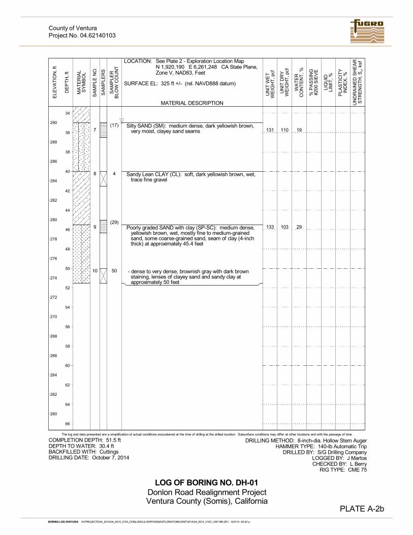
7
8
9
10
19
29
Silty SAND (SM): medium dense, dark yellowish brown,very moist, clayey sand seams
Sandy Lean CLAY (CL): soft, dark yellowish brown, wet,trace fine gravel
Poorly graded SAND with clay (SP-SC): medium dense,yellowish brown, wet, mostly fine to medium-grainedsand, some coarse-grained sand, seam of clay (4-inchthick) at approximately 45.4 feet
- dense to very dense, brownish gray with dark brownstaining, lenses of clayey sand and sandy clay atapproximately 50 feet
110
103
131
133
(17)
4
(29)
50
SA
MP
LER
SMATERIAL DESCRIPTION
PLA
ST
ICIT
YIN
DE
X, %
UN
DR
AIN
ED
SH
EA
RS
TR
EN
GT
H, S
u, k
sf
DE
PT
H, f
t
PLATE A-2b
UN
IT D
RY
WE
IGH
T, p
cf
34
36
38
40
42
44
46
48
50
52
54
56
58
60
62
64
66
LIQ
UID
LIM
IT, %
UN
IT W
ET
WE
IGH
T, p
cf
The log and data presented are a simplification of actual conditions encountered at the time of drilling at the drilled location. Subsurface conditions may differ at other locations and with the passage of time.
SA
MP
LE N
O.
MA
TE
RIA
LS
YM
BO
L
ELE
VA
TIO
N, f
t
WA
TE
RC
ON
TE
NT
, %
% P
AS
SIN
G#2
00 S
IEV
E
SA
MP
LER
BLO
W C
OU
NT
DEPTH TO WATER: 30.4 ft
LOCATION:
DRILLING METHOD: 8-inch-dia. Hollow Stem AugerHAMMER TYPE: 140-lb Automatic Trip
DRILLED BY: S/G Drilling CompanyLOGGED BY: J MartosCHECKED BY: L Berry
RIG TYPE: CME 75
SURFACE EL: 325 ft +/- (rel. NAVD888 datum)
COMPLETION DEPTH: 51.5 ft
DRILLING DATE: October 7, 2014BACKFILLED WITH: Cuttings
LOG OF BORING NO. DH-01
290
288
286
284
282
280
278
276
274
272
270
268
266
264
262
260
See Plate 2 - Exploration Location MapN 1,920,190 E 6,261,248 CA State Plane,Zone V, NAD83, Feet
Project No. 04.62140103
Donlon Road Realignment ProjectVentura County (Somis), California
County of Ventura
BORING LOG VENTURA N:\PROJECTS\04_2014\04_6214_0103_DONLONCULVERTXING\EXPLORATIONS\GINT\2014\04_6214_0103_VAF14B.GPJ 12/5/14 04:20 p
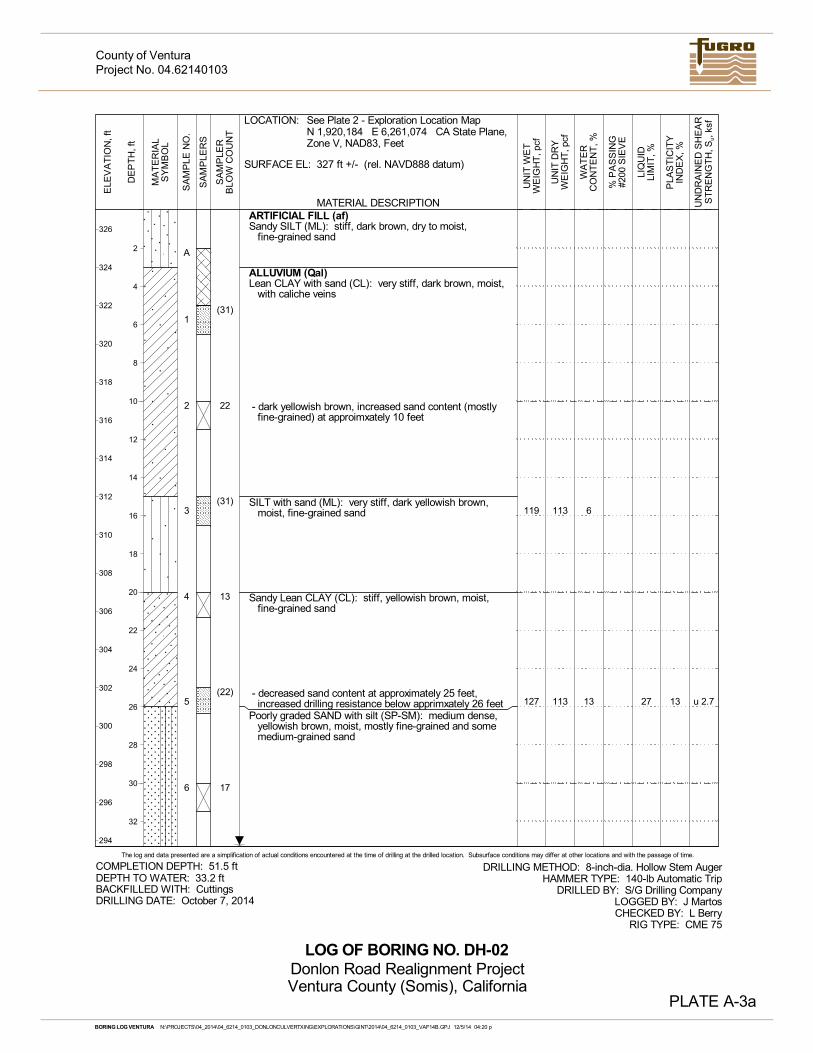
A
1
2
3
4
5
6
6
13
ARTIFICIAL FILL (af)Sandy SILT (ML): stiff, dark brown, dry to moist,
fine-grained sand
ALLUVIUM (Qal)Lean CLAY with sand (CL): very stiff, dark brown, moist,
with caliche veins
- dark yellowish brown, increased sand content (mostlyfine-grained) at approimxately 10 feet
SILT with sand (ML): very stiff, dark yellowish brown,moist, fine-grained sand
Sandy Lean CLAY (CL): stiff, yellowish brown, moist,fine-grained sand
- decreased sand content at approximately 25 feet,increased drilling resistance below apprimxately 26 feet
Poorly graded SAND with silt (SP-SM): medium dense,yellowish brown, moist, mostly fine-grained and somemedium-grained sand
113
113
119
127 u 2.727 13
(31)
22
(31)
13
(22)
17
SA
MP
LER
SMATERIAL DESCRIPTION
PLA
ST
ICIT
YIN
DE
X, %
UN
DR
AIN
ED
SH
EA
RS
TR
EN
GT
H, S
u, k
sf
DE
PT
H, f
t
PLATE A-3a
UN
IT D
RY
WE
IGH
T, p
cf
2
4
6
8
10
12
14
16
18
20
22
24
26
28
30
32
LIQ
UID
LIM
IT, %
UN
IT W
ET
WE
IGH
T, p
cf
The log and data presented are a simplification of actual conditions encountered at the time of drilling at the drilled location. Subsurface conditions may differ at other locations and with the passage of time.
SA
MP
LE N
O.
MA
TE
RIA
LS
YM
BO
L
ELE
VA
TIO
N, f
t
WA
TE
RC
ON
TE
NT
, %
% P
AS
SIN
G#2
00 S
IEV
E
SA
MP
LER
BLO
W C
OU
NT
DEPTH TO WATER: 33.2 ft
LOCATION:
DRILLING METHOD: 8-inch-dia. Hollow Stem AugerHAMMER TYPE: 140-lb Automatic Trip
DRILLED BY: S/G Drilling CompanyLOGGED BY: J MartosCHECKED BY: L Berry
RIG TYPE: CME 75
SURFACE EL: 327 ft +/- (rel. NAVD888 datum)
COMPLETION DEPTH: 51.5 ft
DRILLING DATE: October 7, 2014BACKFILLED WITH: Cuttings
LOG OF BORING NO. DH-02
326
324
322
320
318
316
314
312
310
308
306
304
302
300
298
296
294
See Plate 2 - Exploration Location MapN 1,920,184 E 6,261,074 CA State Plane,Zone V, NAD83, Feet
Project No. 04.62140103
Donlon Road Realignment ProjectVentura County (Somis), California
County of Ventura
BORING LOG VENTURA N:\PROJECTS\04_2014\04_6214_0103_DONLONCULVERTXING\EXPLORATIONS\GINT\2014\04_6214_0103_VAF14B.GPJ 12/5/14 04:20 p
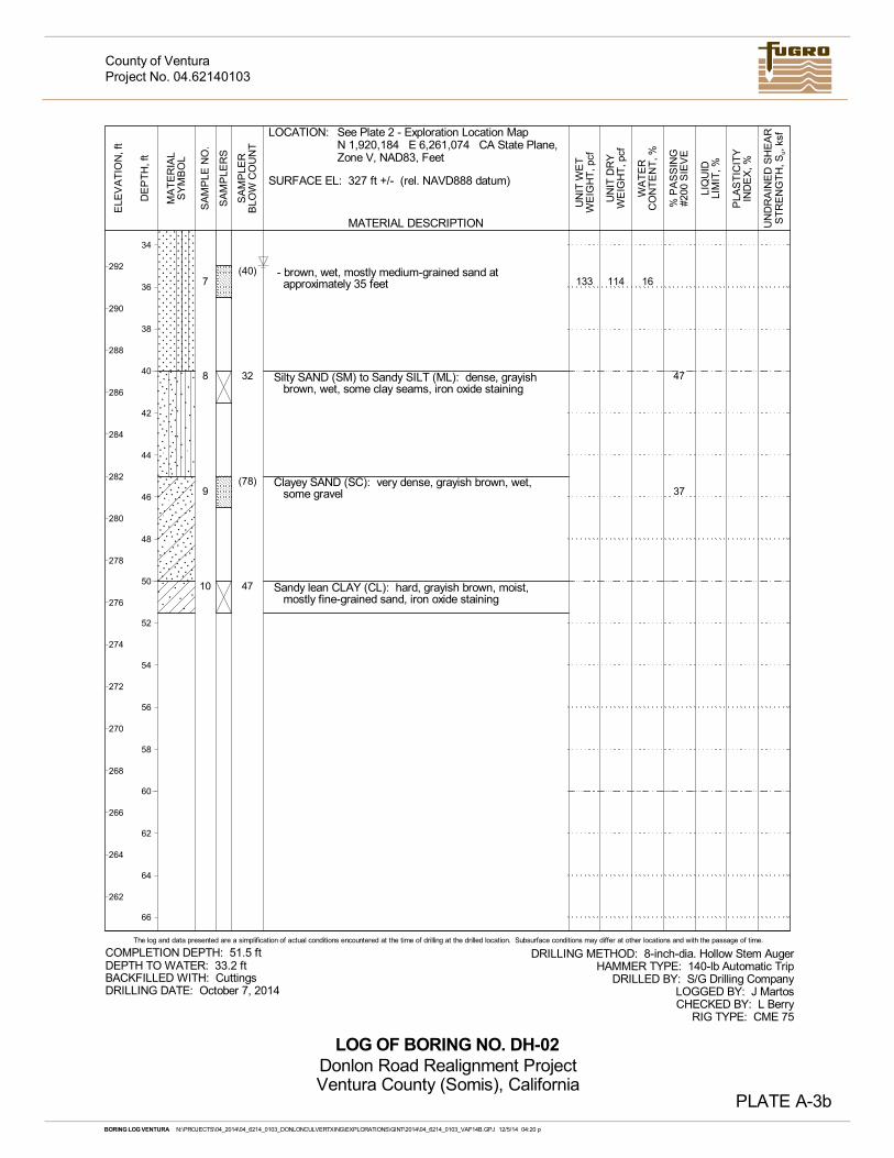
7
8
9
10
16
47
37
- brown, wet, mostly medium-grained sand atapproximately 35 feet
Silty SAND (SM) to Sandy SILT (ML): dense, grayishbrown, wet, some clay seams, iron oxide staining
Clayey SAND (SC): very dense, grayish brown, wet,some gravel
Sandy lean CLAY (CL): hard, grayish brown, moist,mostly fine-grained sand, iron oxide staining
114133(40)
32
(78)
47
SA
MP
LER
SMATERIAL DESCRIPTION
PLA
ST
ICIT
YIN
DE
X, %
UN
DR
AIN
ED
SH
EA
RS
TR
EN
GT
H, S
u, k
sf
DE
PT
H, f
t
PLATE A-3b
UN
IT D
RY
WE
IGH
T, p
cf
34
36
38
40
42
44
46
48
50
52
54
56
58
60
62
64
66
LIQ
UID
LIM
IT, %
UN
IT W
ET
WE
IGH
T, p
cf
The log and data presented are a simplification of actual conditions encountered at the time of drilling at the drilled location. Subsurface conditions may differ at other locations and with the passage of time.
SA
MP
LE N
O.
MA
TE
RIA
LS
YM
BO
L
ELE
VA
TIO
N, f
t
WA
TE
RC
ON
TE
NT
, %
% P
AS
SIN
G#2
00 S
IEV
E
SA
MP
LER
BLO
W C
OU
NT
DEPTH TO WATER: 33.2 ft
LOCATION:
DRILLING METHOD: 8-inch-dia. Hollow Stem AugerHAMMER TYPE: 140-lb Automatic Trip
DRILLED BY: S/G Drilling CompanyLOGGED BY: J MartosCHECKED BY: L Berry
RIG TYPE: CME 75
SURFACE EL: 327 ft +/- (rel. NAVD888 datum)
COMPLETION DEPTH: 51.5 ft
DRILLING DATE: October 7, 2014BACKFILLED WITH: Cuttings
LOG OF BORING NO. DH-02
292
290
288
286
284
282
280
278
276
274
272
270
268
266
264
262
See Plate 2 - Exploration Location MapN 1,920,184 E 6,261,074 CA State Plane,Zone V, NAD83, Feet
Project No. 04.62140103
Donlon Road Realignment ProjectVentura County (Somis), California
County of Ventura
BORING LOG VENTURA N:\PROJECTS\04_2014\04_6214_0103_DONLONCULVERTXING\EXPLORATIONS\GINT\2014\04_6214_0103_VAF14B.GPJ 12/5/14 04:20 p
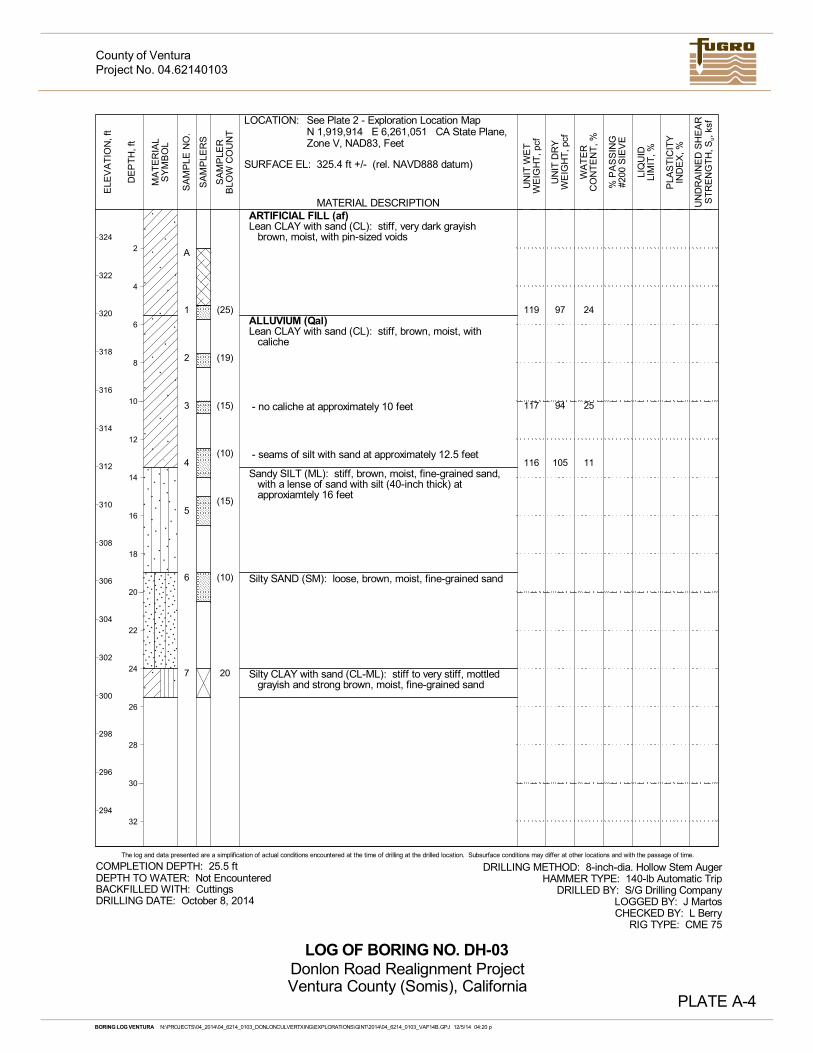
A
1
2
3
4
5
6
7
24
25
11
ARTIFICIAL FILL (af)Lean CLAY with sand (CL): stiff, very dark grayish
brown, moist, with pin-sized voids
ALLUVIUM (Qal)Lean CLAY with sand (CL): stiff, brown, moist, with
caliche
- no caliche at approximately 10 feet
- seams of silt with sand at approximately 12.5 feet
Sandy SILT (ML): stiff, brown, moist, fine-grained sand,with a lense of sand with silt (40-inch thick) atapproxiamtely 16 feet
Silty SAND (SM): loose, brown, moist, fine-grained sand
Silty CLAY with sand (CL-ML): stiff to very stiff, mottledgrayish and strong brown, moist, fine-grained sand
97
94
105
119
117
116
(25)
(19)
(15)
(10)
(15)
(10)
20
SA
MP
LER
SMATERIAL DESCRIPTION
PLA
ST
ICIT
YIN
DE
X, %
UN
DR
AIN
ED
SH
EA
RS
TR
EN
GT
H, S
u, k
sf
DE
PT
H, f
t
PLATE A-4
UN
IT D
RY
WE
IGH
T, p
cf
2
4
6
8
10
12
14
16
18
20
22
24
26
28
30
32
LIQ
UID
LIM
IT, %
UN
IT W
ET
WE
IGH
T, p
cf
The log and data presented are a simplification of actual conditions encountered at the time of drilling at the drilled location. Subsurface conditions may differ at other locations and with the passage of time.
SA
MP
LE N
O.
MA
TE
RIA
LS
YM
BO
L
ELE
VA
TIO
N, f
t
WA
TE
RC
ON
TE
NT
, %
% P
AS
SIN
G#2
00 S
IEV
E
SA
MP
LER
BLO
W C
OU
NT
DEPTH TO WATER: Not Encountered
LOCATION:
DRILLING METHOD: 8-inch-dia. Hollow Stem AugerHAMMER TYPE: 140-lb Automatic Trip
DRILLED BY: S/G Drilling CompanyLOGGED BY: J MartosCHECKED BY: L Berry
RIG TYPE: CME 75
SURFACE EL: 325.4 ft +/- (rel. NAVD888 datum)
COMPLETION DEPTH: 25.5 ft
DRILLING DATE: October 8, 2014BACKFILLED WITH: Cuttings
LOG OF BORING NO. DH-03
324
322
320
318
316
314
312
310
308
306
304
302
300
298
296
294
See Plate 2 - Exploration Location MapN 1,919,914 E 6,261,051 CA State Plane,Zone V, NAD83, Feet
Project No. 04.62140103
Donlon Road Realignment ProjectVentura County (Somis), California
County of Ventura
BORING LOG VENTURA N:\PROJECTS\04_2014\04_6214_0103_DONLONCULVERTXING\EXPLORATIONS\GINT\2014\04_6214_0103_VAF14B.GPJ 12/5/14 04:20 p
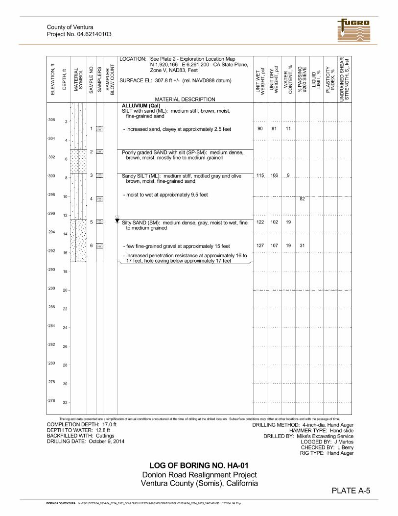
1
2
3
4
5
6
11
9
19
19
82
31
ALLUVIUM (Qal)SILT with sand (ML): medium stiff, brown, moist,
fine-grained sand
- increased sand, clayey at approixmately 2.5 feet
Poorly graded SAND with silt (SP-SM): medium dense,brown, moist, mostly fine to medium-grained
Sandy SILT (ML): medium stiff, mottled gray and olivebrown, moist, fine-grained sand
- moist to wet at approixmately 9.5 feet
Silty SAND (SM): medium dense, gray, moist to wet, fineto medium grained
- few fine-grained gravel at approximately 15 feet
- increased penetration resistance at approximately 16 to17 feet, hole caving below approximately 17 feet
81
106
102
107
90
115
122
127
SA
MP
LER
SMATERIAL DESCRIPTION
PLA
ST
ICIT
YIN
DE
X, %
UN
DR
AIN
ED
SH
EA
RS
TR
EN
GT
H, S
u, k
sf
DE
PT
H, f
t
PLATE A-5
UN
IT D
RY
WE
IGH
T, p
cf
2
4
6
8
10
12
14
16
18
20
22
24
26
28
30
32
LIQ
UID
LIM
IT, %
UN
IT W
ET
WE
IGH
T, p
cf
The log and data presented are a simplification of actual conditions encountered at the time of drilling at the drilled location. Subsurface conditions may differ at other locations and with the passage of time.
SA
MP
LE N
O.
MA
TE
RIA
LS
YM
BO
L
ELE
VA
TIO
N, f
t
WA
TE
RC
ON
TE
NT
, %
% P
AS
SIN
G#2
00 S
IEV
E
SA
MP
LER
BLO
W C
OU
NT
DEPTH TO WATER: 12.8 ft
LOCATION:
DRILLING METHOD: 4-inch-dia. Hand AugerHAMMER TYPE: Hand-slide
DRILLED BY: Mike's Excavating ServiceLOGGED BY: J MartosCHECKED BY: L BerryRIG TYPE: Hand Auger
SURFACE EL: 307.8 ft +/- (rel. NAVD888 datum)
COMPLETION DEPTH: 17.0 ft
DRILLING DATE: October 9, 2014BACKFILLED WITH: Cuttings
LOG OF BORING NO. HA-01
306
304
302
300
298
296
294
292
290
288
286
284
282
280
278
276
See Plate 2 - Exploration Location MapN 1,920,166 E 6,261,200 CA State Plane,Zone V, NAD83, Feet
Project No. 04.62140103
Donlon Road Realignment ProjectVentura County (Somis), California
County of Ventura
BORING LOG VENTURA N:\PROJECTS\04_2014\04_6214_0103_DONLONCULVERTXING\EXPLORATIONS\GINT\2014\04_6214_0103_VAF14B.GPJ 12/5/14 04:20 p
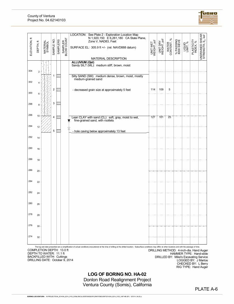
1
2
3
4
5
5
25
ALLUVIUM (Qal)Sandy SILT (ML): medium stiff, brown, moist
Silty SAND (SM): medium dense, brown, moist, mostlymedium-grained sand
- decreased grain size at approximately 5 feet
Lean CLAY with sand (CL): soft, gray, moist to wet,fine-grained sand, with rootlets
- hole caving below approximately 13 feet
109
101
114
127
SA
MP
LER
SMATERIAL DESCRIPTION
PLA
ST
ICIT
YIN
DE
X, %
UN
DR
AIN
ED
SH
EA
RS
TR
EN
GT
H, S
u, k
sf
DE
PT
H, f
t
PLATE A-6
UN
IT D
RY
WE
IGH
T, p
cf
2
4
6
8
10
12
14
16
18
20
22
24
26
28
30
32
LIQ
UID
LIM
IT, %
UN
IT W
ET
WE
IGH
T, p
cf
The log and data presented are a simplification of actual conditions encountered at the time of drilling at the drilled location. Subsurface conditions may differ at other locations and with the passage of time.
SA
MP
LE N
O.
MA
TE
RIA
LS
YM
BO
L
ELE
VA
TIO
N, f
t
WA
TE
RC
ON
TE
NT
, %
% P
AS
SIN
G#2
00 S
IEV
E
SA
MP
LER
BLO
W C
OU
NT
DEPTH TO WATER: 11.1 ft
LOCATION:
DRILLING METHOD: 4-inch-dia. Hand AugerHAMMER TYPE: Hand-slide
DRILLED BY: Mike's Excavating ServiceLOGGED BY: J MartosCHECKED BY: L BerryRIG TYPE: Hand Auger
SURFACE EL: 305.9 ft +/- (rel. NAVD888 datum)
COMPLETION DEPTH: 13.0 ft
DRILLING DATE: October 9, 2014BACKFILLED WITH: Cuttings
LOG OF BORING NO. HA-02
304
302
300
298
296
294
292
290
288
286
284
282
280
278
276
274
See Plate 2 - Exploration Location MapN 1,920,150 E 6,261,180 CA State Plane,Zone V, NAD83, Feet
Project No. 04.62140103
Donlon Road Realignment ProjectVentura County (Somis), California
County of Ventura
BORING LOG VENTURA N:\PROJECTS\04_2014\04_6214_0103_DONLONCULVERTXING\EXPLORATIONS\GINT\2014\04_6214_0103_VAF14B.GPJ 12/5/14 04:20 p
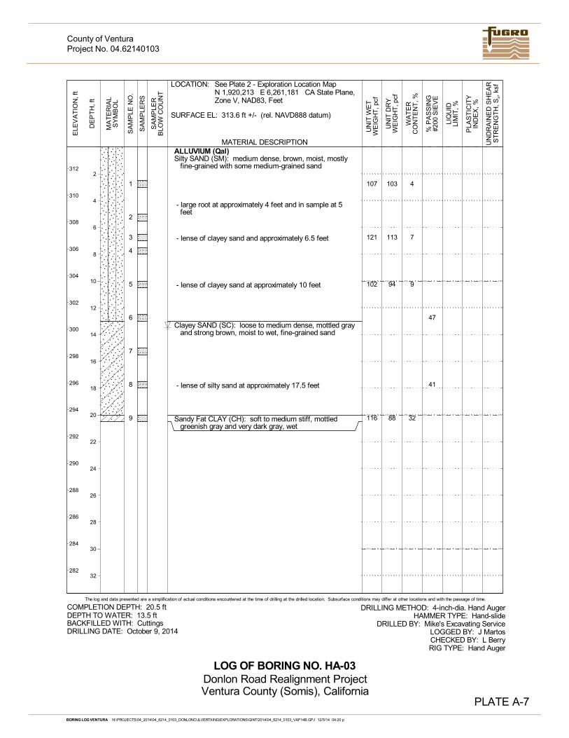
1
2
3
4
5
6
7
8
9
4
7
9
32
47
41
ALLUVIUM (Qal)Silty SAND (SM): medium dense, brown, moist, mostly
fine-grained with some medium-grained sand
- large root at approximately 4 feet and in sample at 5feet
- lense of clayey sand and approximately 6.5 feet
- lense of clayey sand at approximately 10 feet
Clayey SAND (SC): loose to medium dense, mottled grayand strong brown, moist to wet, fine-grained sand
- lense of silty sand at approximately 17.5 feet
Sandy Fat CLAY (CH): soft to medium stiff, mottledgreenish gray and very dark gray, wet
103
113
94
88
107
121
102
116
SA
MP
LER
SMATERIAL DESCRIPTION
PLA
ST
ICIT
YIN
DE
X, %
UN
DR
AIN
ED
SH
EA
RS
TR
EN
GT
H, S
u, k
sf
DE
PT
H, f
t
PLATE A-7
UN
IT D
RY
WE
IGH
T, p
cf
2
4
6
8
10
12
14
16
18
20
22
24
26
28
30
32
LIQ
UID
LIM
IT, %
UN
IT W
ET
WE
IGH
T, p
cf
The log and data presented are a simplification of actual conditions encountered at the time of drilling at the drilled location. Subsurface conditions may differ at other locations and with the passage of time.
SA
MP
LE N
O.
MA
TE
RIA
LS
YM
BO
L
ELE
VA
TIO
N, f
t
WA
TE
RC
ON
TE
NT
, %
% P
AS
SIN
G#2
00 S
IEV
E
SA
MP
LER
BLO
W C
OU
NT
DEPTH TO WATER: 13.5 ft
LOCATION:
DRILLING METHOD: 4-inch-dia. Hand AugerHAMMER TYPE: Hand-slide
DRILLED BY: Mike's Excavating ServiceLOGGED BY: J MartosCHECKED BY: L BerryRIG TYPE: Hand Auger
SURFACE EL: 313.6 ft +/- (rel. NAVD888 datum)
COMPLETION DEPTH: 20.5 ft
DRILLING DATE: October 9, 2014BACKFILLED WITH: Cuttings
LOG OF BORING NO. HA-03
312
310
308
306
304
302
300
298
296
294
292
290
288
286
284
282
See Plate 2 - Exploration Location MapN 1,920,213 E 6,261,181 CA State Plane,Zone V, NAD83, Feet
Project No. 04.62140103
Donlon Road Realignment ProjectVentura County (Somis), California
County of Ventura
BORING LOG VENTURA N:\PROJECTS\04_2014\04_6214_0103_DONLONCULVERTXING\EXPLORATIONS\GINT\2014\04_6214_0103_VAF14B.GPJ 12/5/14 04:20 p

APPENDIX B - LABORATORY TESTING
County of Ventura December 8, 2014 (Project No. 04.62140103)
B-1 O:\MANAGEMENT\04_2014\04_6214_0103_VC_DONLONROADCULVERT\06_REPORTS\04_6214_0103_RPT.DOC
APPENDIX B LABORATORY TESTING
INTRODUCTION
The contents of this appendix should be integrated with the geotechnical engineering study of which it is a part. The data contained in this appendix should not be used in whole or in part as a sole source for information or recommendations regarding the subject sites.
LABORATORY ANALYSES
Laboratory tests were performed on selected driven ring, SPT, and bulk soil samples to estimate engineering characteristics of the various earth materials encountered. Testing was performed in general accordance with Caltrans and ASTM Standards, latest revisions.
Laboratory Moisture and Density Determinations
Moisture content and dry density determinations were performed on selected driven ring samples collected to evaluate the natural water content and dry density of the various soils encountered in accordance with ASTM D2937. Test results are presented on Plate B-1 - Summary of Laboratory Test Results, and on the respective drill hole logs (Appendix A).
Grain Size Distribution
One grain size distributions were determined for select soil samples in accordance with standard test method ASTM D422. In addition, six tests were performed to determine the amount of material in soils finer than the No. 200 Sieve in accordance with ASTM test method D1140. Grain size curves are presented on Plate B-2 - Grain Size Curves. Results of percent passing No. 200 Sieve are shown on Plate B-1 and on the respective drill hole logs.
Atterberg Limits Tests
One Atterberg limits tests was performed on a select soil sample to evaluate liquid and plastic limits in accordance with standard test method ASTM D4318. Test results are shown on Plate B-1, Plate B-3 - Plasticity Chart, and on the respective drill hole logs.
Consolidation Tests
Two dual-odometer consolidation tests were performed on select driven ring samples of fine-grained earth material. Tests were conducted in general accordance with standard test method ASTM D2435, Standard Test Method for One-Dimensional Consolidation Properties of Soils. Consolidation test results are presented on Plates B-4a through B-4b - Consolidation Test Results.
County of Ventura December 8, 2014 (Project No. 04.62140103)
B-2 O:\MANAGEMENT\04_2014\04_6214_0103_VC_DONLONROADCULVERT\06_REPORTS\04_6214_0103_RPT.DOC
Direct Shear Tests
One multistage direct shear tests were performed on select driven ring samples to evaluate the shear strength of earth materials. Tests were performed in accordance with standard test method ASTM D-3080. A summary plot of the direct shear data is presented on Plates B-5 - Direct Shear Test Results.
Unconsolidated - Undrained Triaxial Tests
One unconsolidated, undrained (UU) triaxial test was performed on a select driven ring sample to evaluate the shear strength of earth materials. In a consolidated undrained test the sample is not allowed to drain. Shear characteristics are measured under undrained conditions and the sample is assumed to be fully saturated. The test was performed in accordance with standard test method ASTM D2850. A summary plot of the UU test data is presented on Plate B-6 - Unconsolidated, Undrained Triaxial Test.
Preliminary Corrosion Tests
Soil chemistry tests were performed on three samples to evaluate sulfate, chloride, resistivity, and pH. Testing was performed by Cooper Testing Laboratories of Palo Alto, California. Test results and an analysis of the corrosivity to metal and concrete materials are summarized in Section 8 of this report, and are presented on Plate B-1.
Compaction Test
One compaction test was performed on a selected bulk sample of the onsite soils to assess their compaction characteristics. The test was performed in accordance with ASTM D1557. Test results are presented on Plate B-1 and Plate B-7 - Compaction Test Results.
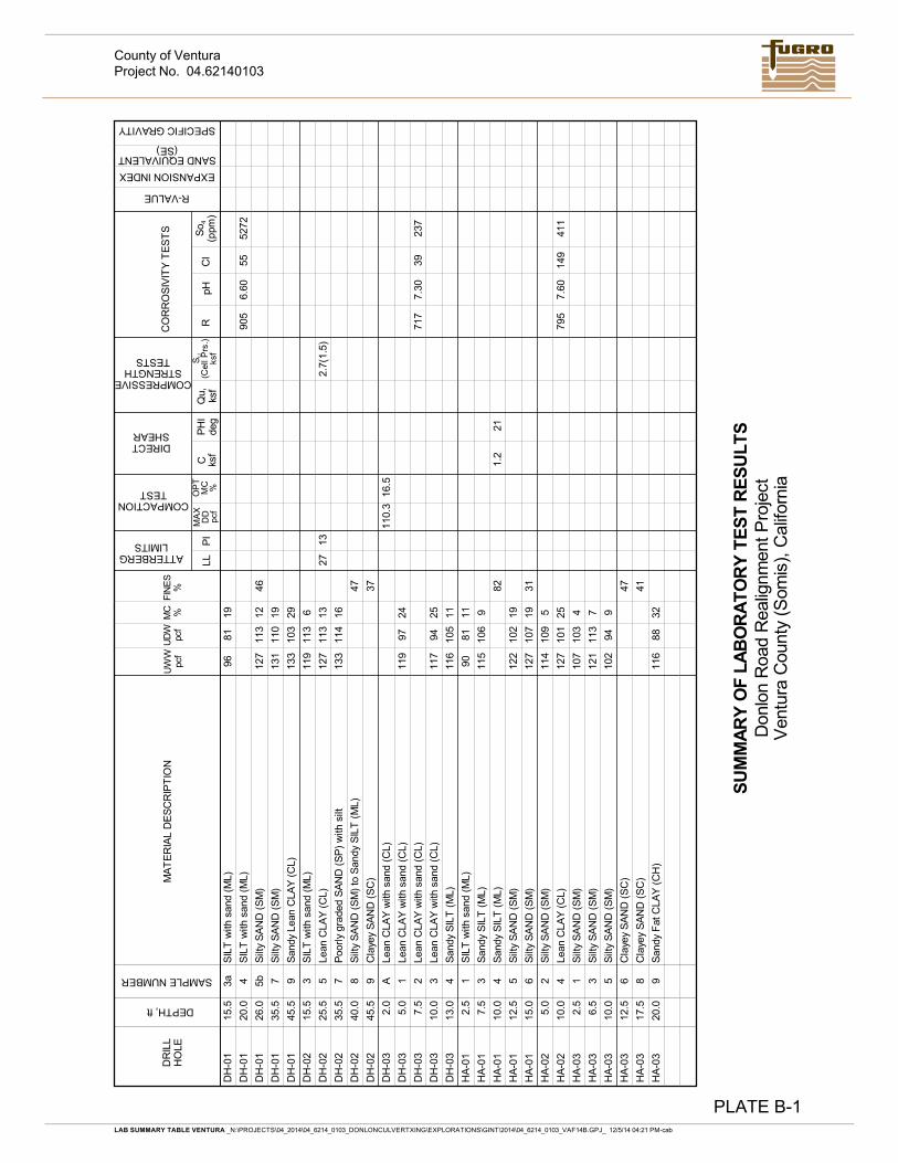
DH
-01
15.5
3aS
ILT
with
san
d (M
L)96
8119
DH
-01
20.0
4S
ILT
with
san
d (M
L)90
56.
6055
5272
DH
-01
26.0
5bS
ilty
SA
ND
(S
M)
127
113
1246
DH
-01
35.5
7S
ilty
SA
ND
(S
M)
131
110
19
DH
-01
45.5
9S
andy
Lea
n C
LAY
(C
L)13
310
329
DH
-02
15.5
3S
ILT
with
san
d (M
L)11
911
36
DH
-02
25.5
5Le
an C
LAY
(C
L)12
711
313
2713
2.7(
1.5)
DH
-02
35.5
7P
oorl
y gr
aded
SA
ND
(S
P)
with
silt
133
114
16
DH
-02
40.0
8S
ilty
SA
ND
(S
M)
to S
andy
SIL
T (
ML)
47
DH
-02
45.5
9C
laye
y S
AN
D (
SC
)37
DH
-03
2.0
ALe
an C
LAY
with
san
d (C
L)11
0.3
16.5
DH
-03
5.0
1Le
an C
LAY
with
san
d (C
L)11
997
24
DH
-03
7.5
2Le
an C
LAY
with
san
d (C
L)71
77.
3039
237
DH
-03
10.0
3Le
an C
LAY
with
san
d (C
L)11
794
25
DH
-03
13.0
4S
andy
SIL
T (
ML)
116
105
11
HA
-01
2.5
1S
ILT
with
san
d (M
L)90
8111
HA
-01
7.5
3S
andy
SIL
T (
ML)
115
106
9
HA
-01
10.0
4S
andy
SIL
T (
ML)
821.
221
HA
-01
12.5
5S
ilty
SA
ND
(S
M)
122
102
19
HA
-01
15.0
6S
ilty
SA
ND
(S
M)
127
107
1931
HA
-02
5.0
2S
ilty
SA
ND
(S
M)
114
109
5
HA
-02
10.0
4Le
an C
LAY
(C
L)12
710
125
795
7.60
149
411
HA
-03
2.5
1S
ilty
SA
ND
(S
M)
107
103
4
HA
-03
6.5
3S
ilty
SA
ND
(S
M)
121
113
7
HA
-03
10.0
5S
ilty
SA
ND
(S
M)
102
949
HA
-03
12.5
6C
laye
y S
AN
D (
SC
)47
HA
-03
17.5
8C
laye
y S
AN
D (
SC
)41
HA
-03
20.0
9S
andy
Fat
CLA
Y (
CH
)11
688
32
SAMPLE NUMBER
EXPANSION INDEX
COMPACTIONTEST
SU
(Cel
l Prs
.)ks
fQ
u,ks
fC ks
fP
I
MC %
UD
Wpc
f
SAND EQUIVALENT(SE)
SPECIFIC GRAVITY
R-VALUE
COMPRESSIVESTRENGTH
TESTS
PH
Ide
g
SU
MM
AR
Y O
F L
AB
OR
AT
OR
Y T
ES
T R
ES
UL
TS
So 4
(ppm
)
LAB SUMMARY TABLE VENTURA _N:\PROJECTS\04_2014\04_6214_0103_DONLONCULVERTXING\EXPLORATIONS\GINT\2014\04_6214_0103_VAF14B.GPJ_ 12/5/14 04:21 PM-cab
FIN
ES
%
MA
XD
Dpc
f
ATTERBERGLIMITS
DEPTH, ft
Don
lon
Roa
d R
ealig
nmen
t Pro
ject
Ven
tura
Cou
nty
(Som
is),
Cal
iforn
ia
DR
ILL
HO
LE
LL
UW
Wpc
f
OP
TM
C %
DIRECTSHEAR
Cl
RpH
CO
RR
OS
IVIT
Y T
ES
TS
PLATE B-1
MA
TE
RIA
L D
ES
CR
IPT
ION
Project No. 04.62140103County of Ventura
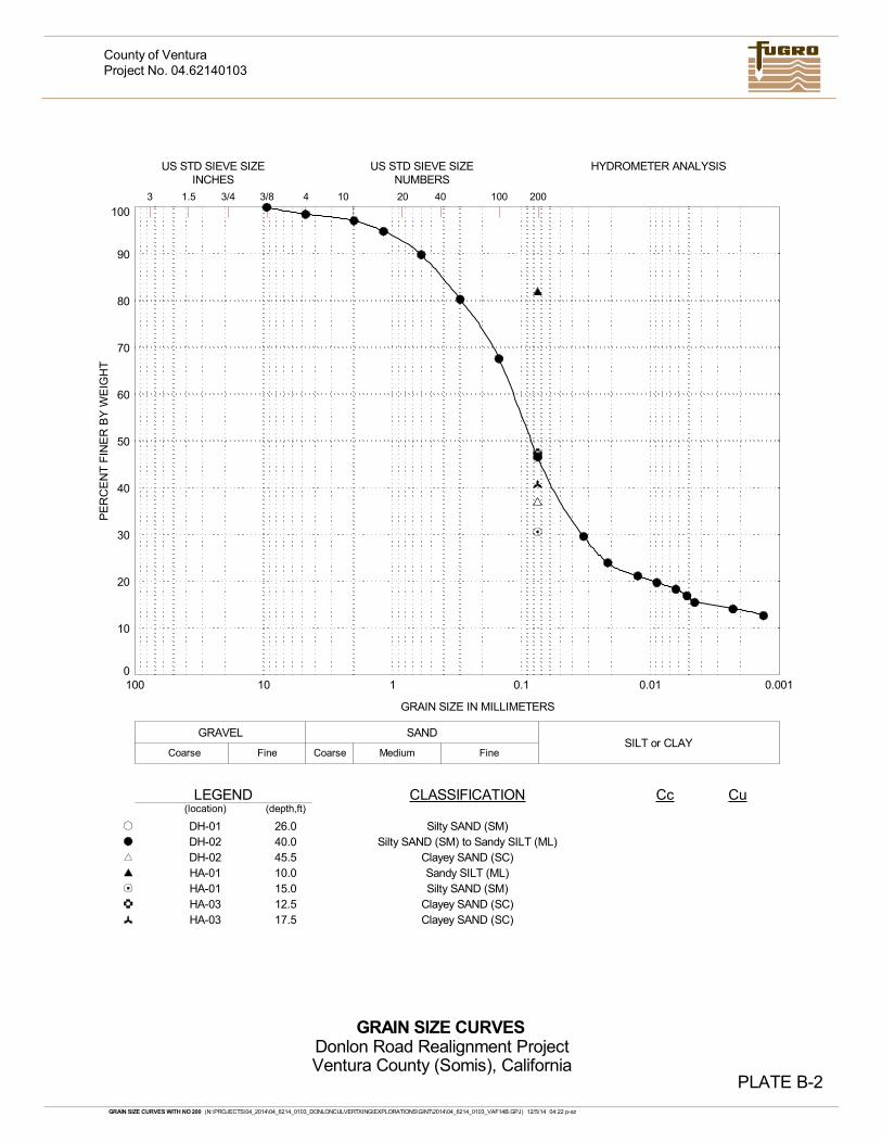
0
10
20
30
40
50
60
70
80
90
100
0.0010.010.1110100
PLATE B-2
SANDSILT or CLAY
Fine Coarse
PE
RC
EN
T F
INE
R B
Y W
EIG
HT
Medium FineCoarse
GRAIN SIZE IN MILLIMETERS
GRAVEL
GRAIN SIZE CURVES
Project No. 04.62140103
Donlon Road Realignment ProjectVentura County (Somis), California
County of Ventura
GRAIN SIZE CURVES WITH NO 200 (N:\PROJECTS\04_2014\04_6214_0103_DONLONCULVERTXING\EXPLORATIONS\GINT\2014\04_6214_0103_VAF14B.GPJ) 12/5/14 04:22 p-sz
HYDROMETER ANALYSIS
20
LEGEND
10 40 1003 1.5 3/4 3/8 4
(depth,ft)CLASSIFICATION Cc Cu
Silty SAND (SM)Silty SAND (SM) to Sandy SILT (ML)
Clayey SAND (SC)Sandy SILT (ML)Silty SAND (SM)
Clayey SAND (SC)Clayey SAND (SC)
DH-01DH-02DH-02HA-01HA-01HA-03HA-03
(location)
US STD SIEVE SIZEINCHES
200
US STD SIEVE SIZENUMBERS
26.040.045.510.015.012.517.5
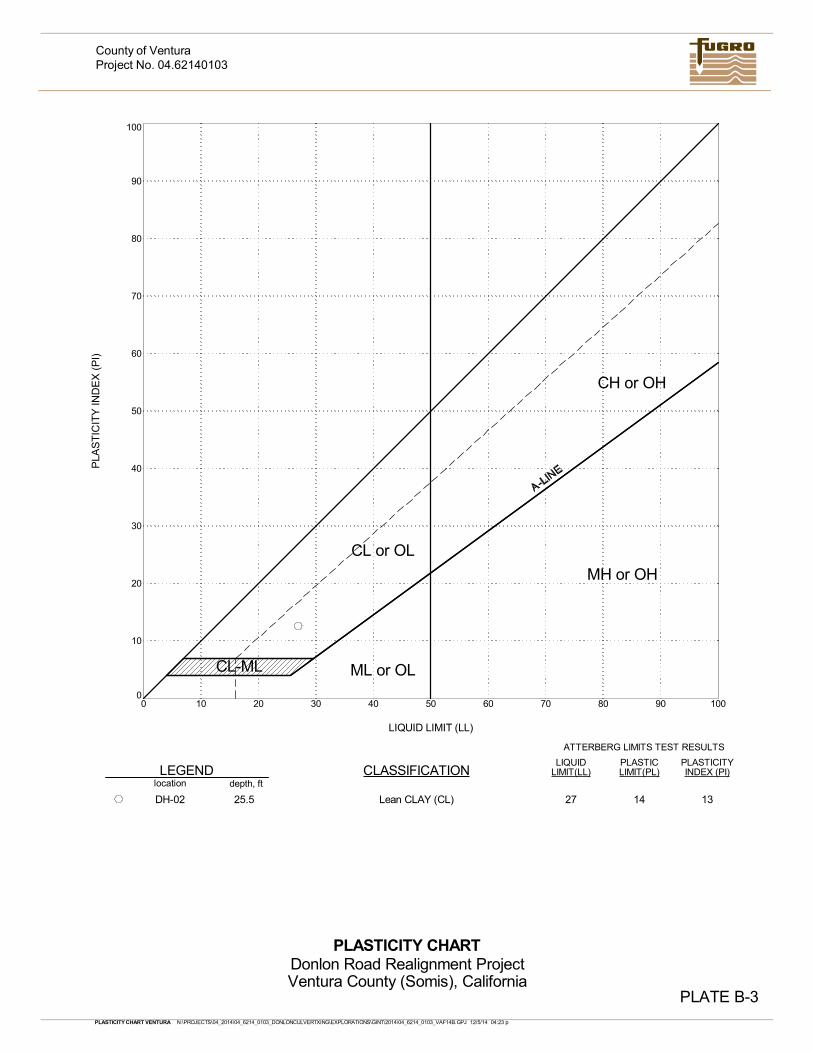
0
10
20
30
40
50
60
70
80
90
100
0 10 20 30 40 50 60 70 80 90 100
25.5DH-02 27
CH or OH
CL or OL
ML or OL
MH or OH
LEGENDlocation
LIQUID LIMIT (LL)
PLASTICITYLIQUIDLIMIT(LL)
PLASTICLIMIT(PL)
Lean CLAY (CL)
depth, ft
ATTERBERG LIMITS TEST RESULTS
PLA
ST
ICIT
Y IN
DE
X (
PI)
INDEX (PI)CLASSIFICATION
CL-ML
PLASTICITY CHART
PLATE B-3
14 13
PLASTICITY CHART VENTURA N:\PROJECTS\04_2014\04_6214_0103_DONLONCULVERTXING\EXPLORATIONS\GINT\2014\04_6214_0103_VAF14B.GPJ 12/5/14 04:23 p
Project No. 04.62140103
Donlon Road Realignment ProjectVentura County (Somis), California
County of Ventura
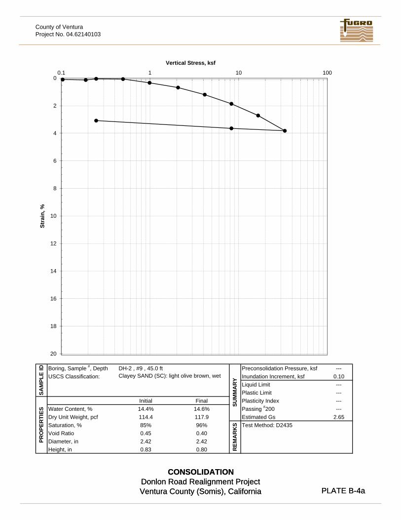
County of VenturaProject No. 04.62140103
X Y X YMax Curvature 4 3Max Curve Tangent 2 2.314802
4 311 4
Horiz Max 4 311 3
Bisect 4 311 3.5
Virgin 6 116 7
Intersect 8.87361 3.393825
Vertical Stress, ksf
0
2
4
6
8
10
12
14
16
0.1 1 10 100
Stra
in, %
Vertical Stress, ksf
CONSOLIDATIONDonlon Road Realignment ProjectVentura County (Somis), California PLATE B-4a
---0.10------------
2.65Passing #200Estimated Gs
SUM
MA
RY
REM
AR
KS Test Method: D2435
Plasticity Index
Inundation Increment, ksfPreconsolidation Pressure, ksf
Liquid LimitPlastic Limit
DH-2 , #9 , 45.0 ft
0.83
14.6%117.996%0.402.420.80
Clayey SAND (SC): light olive brown, wet
FinalInitial
Saturation, %
PRO
PER
TIES
85%114.414.4%
Diameter, inHeight, in
Void Ratio 0.452.42
SAM
PLE
ID
Water Content, %Dry Unit Weight, pcf
USCS Classification:Boring, Sample #, Depth
16
18
20
CONSOLIDATIONDonlon Road Realignment ProjectVentura County (Somis), California PLATE B-4a
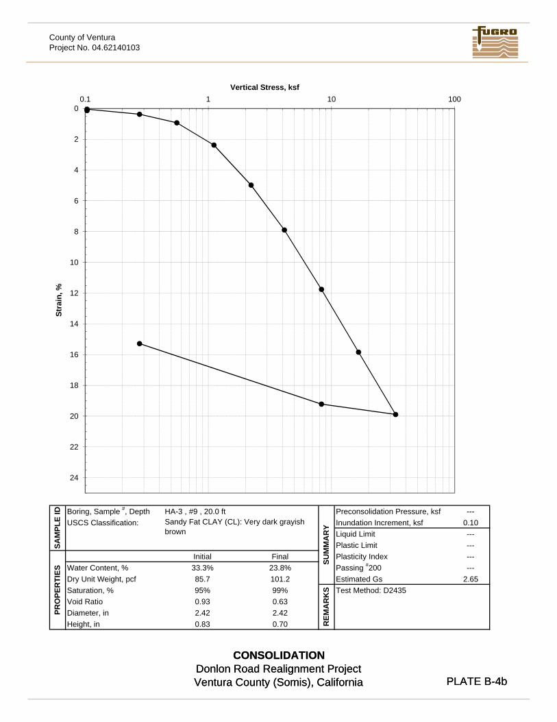
County of VenturaProject No. 04.62140103
X Y X YMax Curvature 4 3Max Curve Tangent 2 2.314802
4 311 4
Horiz Max 4 311 3
Bisect 4 311 3.5
Virgin 6 116 7
Intersect 8.87361 3.393825
Vertical Stress, ksf
0
2
4
6
8
10
12
14
16
18
20
0.1 1 10 100
Stra
in, %
Vertical Stress, ksf
CONSOLIDATIONDonlon Road Realignment ProjectVentura County (Somis), California PLATE B-4b
---0.10------------
2.65Passing #200Estimated Gs
SUM
MA
RY
REM
AR
KS Test Method: D2435
Plasticity Index
Inundation Increment, ksfPreconsolidation Pressure, ksf
Liquid LimitPlastic Limit
HA-3 , #9 , 20.0 ft
0.83
23.8%101.299%0.632.420.70
Sandy Fat CLAY (CL): Very dark grayish brown
FinalInitial
Saturation, %
PRO
PER
TIES
95%85.7
33.3%
Diameter, inHeight, in
Void Ratio 0.932.42
SAM
PLE
ID
Water Content, %Dry Unit Weight, pcf
USCS Classification:Boring, Sample #, Depth
20
22
24
CONSOLIDATIONDonlon Road Realignment ProjectVentura County (Somis), California PLATE B-4b
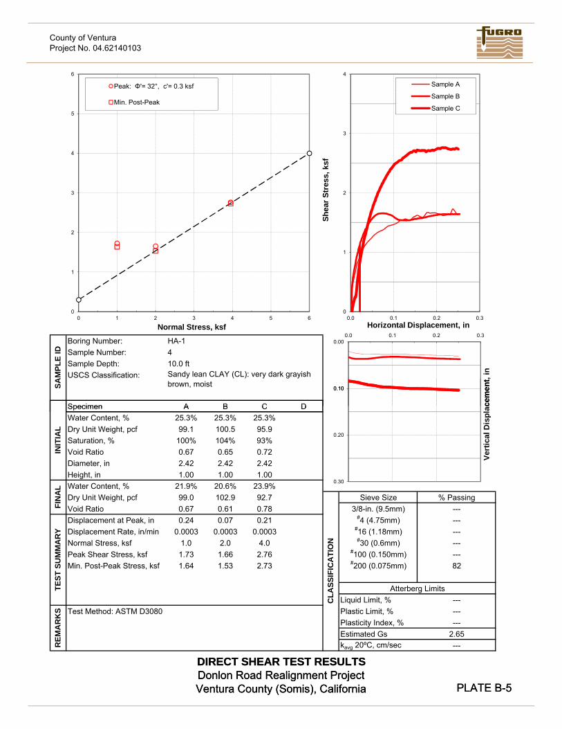
County of VenturaProject No. 04.62140103
Sample Number:
A B C D
Sample Depth: 10.0 ft
Specimen
SAM
PLE
ID
Boring Number: HA-1
USCS Classification: Sandy lean CLAY (CL): very dark grayish brown, moist
4
0
1
2
3
4
5
6
0 1 2 3 4 5 6
Normal Stress, ksf
Peak: Φ'= 32°, c'= 0.3 ksf
Min. Post-Peak
0
1
2
3
4
0.0 0.1 0.2 0.3Horizontal Displacement, in
Sample A
Sample B
Sample C
0.00
0.10
0.0 0.1 0.2 0.3
acem
ent,
in
Shea
r Str
ess,
ksf
DIRECT SHEAR TEST RESULTSDonlon Road Realignment ProjectVentura County (Somis), California PLATE B-5
A B C D25.3% 25.3% 25.3%99.1 100.5 95.9
100% 104% 93%0.67 0.65 0.722.42 2.42 2.421.00 1.00 1.00
21.9% 20.6% 23.9%99.0 102.9 92.70.67 0.61 0.780.24 0.07 0.21
0.0003 0.0003 0.00031.0 2.0 4.01.73 1.66 2.761.64 1.53 2.73
Test Method: ASTM D3080
Peak Shear Stress, ksf
REM
AR
KS
CLA
SSIF
ICA
TIO
N
INIT
IAL
FIN
AL
TEST
SU
MM
AR
Y
Water Content, %
Diameter, inHeight, in
Dry Unit Weight, pcfVoid Ratio
Min. Post-Peak Stress, ksf
Displacement at Peak, in
82
% Passing---------
---
#16 (1.18mm)#30 (0.6mm)
#100 (0.150mm)---Normal Stress, ksf
Dry Unit Weight, pcfSaturation, %
SpecimenWater Content, %
Displacement Rate, in/min
Void Ratio
3/8-in. (9.5mm)#4 (4.75mm)
Sieve Size
kavg 20ºC, cm/sec ---2.65
Plasticity Index, %
Liquid Limit, %
#200 (0.075mm)
---Estimated Gs
Plastic Limit, %------
Atterberg Limits
0.10
0.20
0.30Ve
rtic
al D
ispl
acem
ent
DIRECT SHEAR TEST RESULTSDonlon Road Realignment ProjectVentura County (Somis), California PLATE B-5
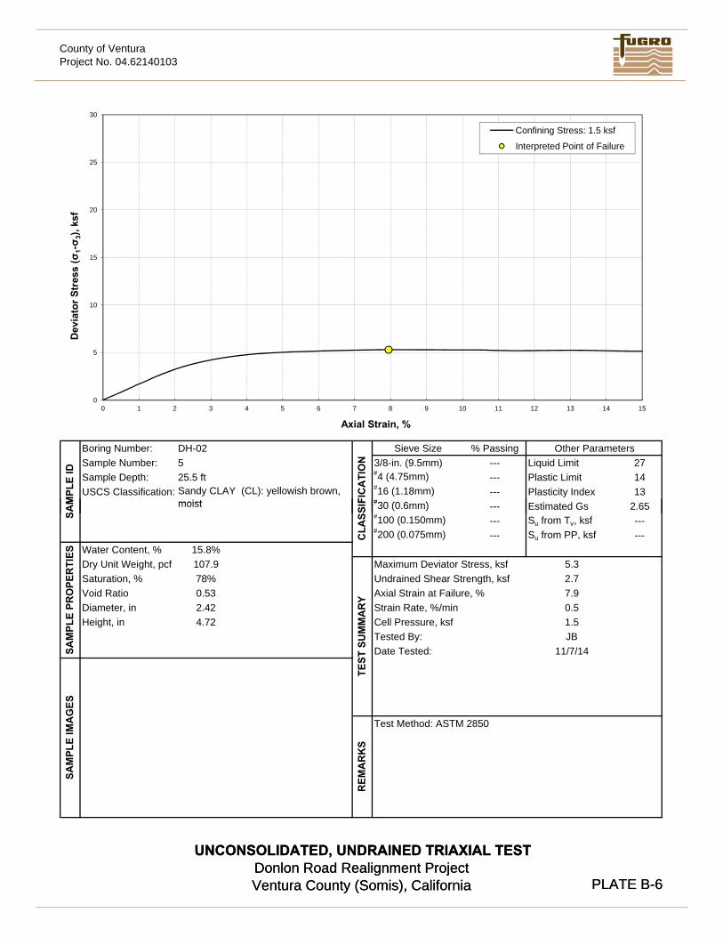
County of VenturaProject No. 04.62140103
Confining Stress: 1.5 ksf
Sieve Size % Passing3/8-in. (9.5mm) --- 27#4 (4.75mm) --- 14#16 (1.18mm) --- 13#30 (0 6 ) 2 65M
PLE
ID
E ti t d G
Boring Number:
Sample Depth:USCS Classification:
Sample Number:DH-025
Sandy CLAY (CL): yellowish brown, moist
Liquid LimitPlastic Limit25.5 ftPlasticity Index
FIC
ATI
ON
Other Parameters
0
5
10
15
20
25
30
0 1 2 3 4 5 6 7 8 9 10 11 12 13 14 15
Dev
iato
r Str
ess
(σ1-σ 3
), ks
f
Axial Strain, %
Confining Stress: 1.5 ksf
Interpreted Point of Failure
UNCONSOLIDATED, UNDRAINED TRIAXIAL TESTDonlon Road Realignment ProjectVentura County (Somis), California PLATE B-6
#30 (0.6mm) --- 2.65#100 (0.150mm) --- ---#200 (0.075mm) --- ---
15.8%107.978%0.532.424.72
Test Method: ASTM 2850
REM
AR
KS
Saturation, %
SAM Estimated Gs
Su from Tv, ksfSu from PP, ksf
5.32.7
moist
SAM
PLE
IMA
GES
Diameter, inHeight, in
SAM
PLE
PRO
PER
TIES
Void Ratio
Water Content, %Dry Unit Weight, pcf
1.5
CLA
SSIF
JB11/7/14
Tested By:
Axial Strain at Failure, %
TEST
SU
MM
AR
Y
Strain Rate, %/min
Date Tested:
Maximum Deviator Stress, ksfUndrained Shear Strength, ksf
Cell Pressure, ksf
7.90.5
UNCONSOLIDATED, UNDRAINED TRIAXIAL TESTDonlon Road Realignment ProjectVentura County (Somis), California PLATE B-6
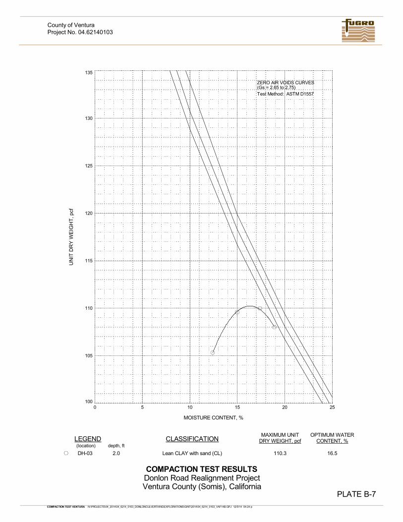
100
105
110
115
120
125
130
135
0 5 10 15 20 25
OPTIMUM WATERCONTENT, %
MOISTURE CONTENT, %
UN
IT D
RY
WE
IGH
T, p
cf
LEGENDMAXIMUM UNIT
DRY WEIGHT, pcf
Test Method: ASTM D1557(Gs = 2.65 to 2.75)
CLASSIFICATION
110.3 16.5
depth, ft
PLATE B-7
COMPACTION TEST RESULTS
(location)
Lean CLAY with sand (CL)
ZERO AIR VOIDS CURVES
2.0DH-03
COMPACTION TEST VENTURA N:\PROJECTS\04_2014\04_6214_0103_DONLONCULVERTXING\EXPLORATIONS\GINT\2014\04_6214_0103_VAF14B.GPJ 12/5/14 04:24 p
Project No. 04.62140103
Donlon Road Realignment ProjectVentura County (Somis), California
County of Ventura